TACKLE BLOCK WARNING, USE & MAINTENANCE ......BLOCKS & SHEAVES 281 TACKLE BLOCK WARNING, USE &...
25
Transcript of TACKLE BLOCK WARNING, USE & MAINTENANCE ......BLOCKS & SHEAVES 281 TACKLE BLOCK WARNING, USE &...

BL
OC
KS
& S
HE
AV
ES
279
TACKLE BLOCK WARNING, USE & MAINTENANCE INFORMATION
The Crosby Group, Inc.
ImportantFor maximum safety and efficiency, tackle block systems must be properly designed, used, and maintained. You must understand the use of tackle block components in the system. These instructions provide this knowledge. Read them carefully and completely.
Some parts of these instructions must use technical words and detailed explanations. NOTE: If you do not understand all words, diagrams, and definitions — DO NOT TRY TO USE A TACKLE BLOCK SYSTEM!
KEEP INSTRUCTIONS FOR FUTURE USE — DO NOT THROW AWAY!
General Cautions or WarningsRatings shown in Crosby Group literature are applicable only to new or “in as new” products.
Working Load Limit ratings indicate the greatest force or load a product can carry under usual environmental conditions. Shock loading and extraordinary conditions must be taken into account when selecting products for use in tackle block systems.
In general, the products displayed in Crosby Group literature are used as parts of a system being employed to accomplish a task. Therefore, we can only recommend within the Working Load Limits, or other stated limitations, the use of products for this purpose.
The Working Load Limit or Design (Safety) Factor of each Crosby product may be affected by wear, misuse, overloading, corrosion, deformation, intentional alteration, and other use conditions. Regular inspection must be conducted to determine whether use can be continued at the catalog assigned WLL, a reduced WLL, a reduced Design (Safety) Factor, or withdrawn from service.
Crosby Group products generally are intended for tension or pull. Side loading must be avoided, as it exerts additional force or loading which the product is not designed to accommodate.
Always make sure the hook supports the load. The latch must never support the load.
Welding of load supporting parts or products can be hazardous. Knowledge of materials, heat treatment, and welding procedures is necessary for proper welding. Crosby Group should be consulted for information.
DefinitionsStatic Load — The load resulting from a constantly applied force or load.
Working Load Limit — The maximum mass or force which the product is authorized to support in general service when the pull is applied in-line, unless noted otherwise, with respect to the center line of the product. This term is used interchangeably with the following terms.
1. WLL
2. Rated Load Value
3. SWL
4. Safe Working Load
5. Resultant Safe Working Load
Working Load — The maximum mass or force which the product is authorized to support in a particular service.
Proof Load — The average force applied in the performance of a proof test; the average force to which a product may be subjected before deformation occurs.
Proof Test — A test applied to a product solely to determine non conforming material or manufacturing defects.
Ultimate Load — The average load or force at which the product fails, or no longer supports the load.
Shock Load — A force that results from the rapid application of a force (such as impacting and/or jerking) or rapid movement of a static load. A shock load significantly adds to the static load.
Design (Safety) Factor — An industry term denoting a product’s theoretical reserve capability; usually computed by dividing the catalog Ultimate Load by the Working Load Limit. Generally expressed for blocks as a ratio of 4 to 1.
Tackle Block — An assembly consisting of a sheave(s), side plates, and generally an end fitting (hook, shackle, etc.) that is used for lifting, lowering, or applying tension.
Fitting MaintenanceFittings, including hooks, shackles, links, etc., may become worn and disfigured with use, resulting in nicks, gouges and sharp corners which produce additional stress conditions. Regular inspection is recommended to monitor product condition.

BL
OC
KS
& S
HE
AV
ES
280 www.certex.com
TACKLE BLOCK WARNING, USE & MAINTENANCE INFORMATION
The Crosby Group, Inc.
Grinding is the recommended procedure to restore smooth surfaces. A reduction of the products original dimension of 10 percent from wear and repair is allowable in the load bearing areas. Any greater reduction may necessitate a reduced Working Load Limit.
Any crack or deformation in a fitting is sufficient cause to withdraw the product from service.
Selection GuideSome of the blocks shown in Crosby Group literature are named for their intended use and selection is routine. A few examples include the “Double Rig Trawl Block” used in the fishing industry, the “Well Loggers Block” used in the oil drilling industry, and the “Cargo Hoisting Block” used in the freighter boat industry. Others are more generally classified and have a variety of uses. They include snatch blocks, regular wood blocks, standard steel blocks, etc. For example, snatch blocks allow the line to be attached by opening up the block instead of threading the line through the block. This feature eliminates the use of rope guards and allows various line entrance and exit angles to change direction of the load. These angles determine the load on the block and/or the block fitting. (See “Loads on Blocks.”) Snatch blocks are intended for infrequent and intermittent use with low line speeds.
A tackle block is one element of a system used to lift or drag a load. There are other elements in the system including the prime mover (hoist, winch, hand), supporting structure, power available, etc. All of these elements can influence the type of tackle block required. When selecting a block for the system in your specific application, you should consider the other elements as well as the features of the blocks shown in Crosby Group literature.
To select a tackle block to fit your requirements, consider the following points:
1. Are there regulations which could affect your choice of blocks, such as federal or state OSHA, elevator safety, mine safety, maritime, insurance, etc.?
2. What is the weight of the load, including any dynamics of impacts that add to load value? You must know this to determine the minimum required Working Load Limit value of the block.
3. How many parts of line are required? This can be determined given the load to be lifted and the line pull you have available. As an alternative, you could calculate the line pull required with a given number of parts of line and a given load weight. (See “How to Figure Line Parts.”)
4. What is the size of line to be used? Multiply the available line pull by the desired safety factor for wire rope to determine the minimum catalog wire rope breaking strength; consult a wire rope catalog for the corresponding grade and diameter of wire rope to match. You should also consider fatigue factors that affect wire rope life. (See “Sheave Size & Wire Rope Strength.”)
5. What is the speed of the line? This will help you determine the type of sheave bearing necessary. There are several choices of bearings suitable for different applications including:
Common (Plain) Bore for very low line speeds and very infrequent use (high bearing friction).
Self Lubricating Bronze Bushings for slow line speeds and infrequent use (moderate bearing friction).
Bronze Bushing with pressure lubrication for slow line speeds and more frequent use at greater loads (moderate bearing friction).
Anti-friction Bearings for faster line speeds and more frequent use at greater loads (minimum bearing friction).
6. What type of fitting is required for your application? The selection may depend on whether the block will be traveling or stationary. Your choices include single or multiple hooks with or without throat latches and shackles, which are the most secured load attachment. You should also decide whether the fitting should be fixed, swivel or swivel with lock. If it is a swivel fitting, then a selection of thrust bearing may be necessary. There are plain fittings with no bearings for positioning at no load, bronze bushed fittings for infrequent and moderate load swiveling, and anti-friction bearing equipped fittings for frequent load swiveling.
7. How will the block be reeved and does it require a dead end becket? (See “The Reeving of Tackle Blocks.”)
8. If the block is to be a traveling block, what weight is required to overhaul the line? (See “How to Determine Overhaul Weights.”)
9. What is the fleet angle of the wire line? Line entrance and exit angles should be no more than 1 1/2°.
10. How will the block be maintained? Do conditions in your application require special maintenance considerations? (See “Tackle Block Maintenance,” and “Fitting Maintenance.”)

BL
OC
KS
& S
HE
AV
ES
281
TACKLE BLOCK WARNING, USE & MAINTENANCE INFORMATION
The Crosby Group, Inc.
Tackle Block MaintenanceTackle Blocks must be regularly inspected, lubricated, and maintained for peak efficiency and extended usefulness. Their proper use and maintenance is equal in importance to other mechanical equipment. The frequency of inspection and lubrication is dependent upon frequency and periods of use, environmental conditions, and the user’s good judgment.
InspectionAs a minimum, the following points should be considered:
1. Wear on pins or axles, rope grooves, side plates, bushing or bearings, and fittings (See Fitting Maintenance). Excessive wear may be a cause to replace parts or remove block from service.
2. Deformation in side plates, pins and axles, fitting attachment points, trunnions, etc. Deformation can be caused by abusive service and/or overload and may be a cause to remove block from service.
3. Misalignment or wobble in sheaves.
4. Security of nuts, bolts, and other locking methods, especially after reassembly following a tear down inspection. Original securing method should be used; e.g., staking, set screw, cotter pin, cap screw.
5. Pins retained by snap rings should be checked for missing or loose rings.
6. Sheave pin nuts should be checked for proper positioning. Pins for tapered roller bearings should be tightened to remove all end play during sheave rotation. Pins for bronze bushings and straight roller bearings should have a running clearance of .031 inch per sheave of end play and should be adjusted accordingly.
7. Hook or shackle to swivel case clearance is set at .031 to.062 at the factory. Increased clearance can result from component wear. Clearance exceeding .12 to .18 should necessitate disassembly and further inspection.
8. Deformation or corrosion of hook and nut threads.
9. Surface condition and deformation of hook (See Fitting Maintenance and ANSI B30.10.)
10. Welded side plates for weld corrosion or weld cracking.
11. Hook latch for deformation, proper fit and operation.
LubricationThe frequency of lubrication depends upon frequency and period of product use as well as environmental conditions, which are contingent upon the user’s good judgment.
Assuming normal product use, the following schedule is suggested when using lithum-base grease of a medium consistency.
Sheave BearingsTapered Roller Bearings — Every 40 hours of continuous operation or every 30 days of intermittent operation.
Roller Bearings — Every 24 hours of continuous operation or every 14 days of intermittent operation.
Bronze Bushings — (Not Self Lubricated) — Every 8 hours of continuous operation or every 14 days of intermittent operation.
Hook BearingsAnti Friction — Every 14 days for frequent swiveling; every 45 days for infrequent swiveling.
Bronze Thrust Bushing or No Bearing — Every 16 hours for frequent swiveling; every 21 days for infrequent swiveling.
Tackle Block Maintenance also depends upon proper block selection (see “Loads on Blocks”), proper reeving (see “The Reeving of Tackle Blocks”), consideration of shock loads, side loading, and other adverse conditions.
Sheave Bearing Application InformationBronze Bushings —Bronze Bushings are used primarily for sheave applications using slow line speed, moderate load, and moderate use. The performance capability of a bearing is related to the bearing pressure and the bearing surface velocity by a relationship known as true PV (Maximum Pressure - Velocity Factor). The material properties of the Bronze Bushings furnished as standard in Crosby catalog sheaves are:
(BP) Maximum Bearing Pressure: 4500 PSI
(BV) Maximum Velocity at bearing: 1200 FPM
(PV) Maximum Pressure Velocity Factor: 55000
(It should be noted that due to material property relations, the maximum BP times the maximum BV is NOT equal to the maximum PV.)

BL
OC
KS
& S
HE
AV
ES
282 www.certex.com
TACKLE BLOCK WARNING, USE & MAINTENANCE INFORMATION
Formula for Calculating Bearing Pressure:
BP =Line Pull × Angle FactorShaft Size × Hub Width
Formula for Calculating Bearing Velocity:
BV =PVBP
Formula for Calculating Line Speed:
Line Speed =BV (Tread Diameter + Rope Diameter)
Shaft Diameter
Calculations can be made to find the maximum allowable line speed for a given total sheave load. If the required line speed is greater than the maximum allowable line speed calculated, then increase the shaft size and/or the hub width and recalculate. Continue the process until the maximum allowable line speed is equal to or exceeds the required line speed.
Example: Using a 14 in. sheave (Stock # 917191; refer to wire rope sheave section of Crosby's General Catalog for dimensions) with a 4600 lb. line pull and an 80° angle between lines determine maximum allowable line speed.
BP = (4600 lb. × 1.53) ÷ (1.50 × 1.62) = 2896 PSI
|LINE PULL
|ANGLE
FACTOR
|SHAFT SIZE
|HUB
WIDTH BV = 55000 ÷ 2896 = 19 FPM Allowable
|PV
FACTOR
|BP
Line Speed = 19 × (12 + .75 ÷ 1.50 = 161.5 FPM ALLOWABLE |BV
|TREAD
DIA.
|ROPESIZE
|SHAFT
DIA.
If the application required a line speed equal to 200 FPM, then another calculation would be necessary. Trying another 14 in. sheave (stock # 4104828) under the same loading conditions, the results are as follows:
BP = (4600 lbs. × 1.53) ÷ (2.75 × 2.31) = 1108 PSI BV = 55000 ÷ 1108 = 50 FPM
Line Speed = 50 × (12.25 + .75) ÷ 2.75 = 236 FPM ALLOWABLE
Common (Plain) Bore — Very slow line speed, very infrequent use, low load.
Roller Bearing — Faster line speeds, more frequent use, greater load. Refer to manufacturer’s rating.
Loads on BlocksThe Working Load Limit (WLL) for Crosby Group blocks indicates the maximum load that should be exerted on the block and its connecting fitting. This total load value may be different from the weight being lifted or pulled by a hoisting or hauling system. It is necessary to determine the total load being imposed on each block in the system to properly determine the rated capacity block to be used. A single sheave block used to change load line direction can be subjected to total loads greatly different from the weight being lifted or pulled. The total load value varies with the angle between the incoming and departing lines to the block.
The following chart indicates the factor to be multiplied by the line pull to obtain the total load on the block.
The Crosby Group, Inc.
Angle Factor Multipliers
Angle Factor Angle Factor
0º 2.00 100º 1.2910º 1.99 110° 1.1520º 1.97 120° 1.0030º 1.93 130° .8440º 1.87 135° .7645º 1.84 140° .6850º 1.81 150° .5260º 1.73 160° .3570º 1.64 170° .1780º 1.53 180° .00 90º 1.41 — —

BL
OC
KS
& S
HE
AV
ES
283
TACKLE BLOCK WARNING, USE & MAINTENANCE INFORMATION
Example A:
(Calculations for determining total load on single line system.)
Example B:
(Calculation for determining total load value for mechanical advantage system.)
Hoisting system lifting 1,000 lbs. using a traveling block. The mechanical advantage of traveling block C is 2.00 because two (2) parts of load line support the 1,000 lb. Weight. (To determine single line pull for various bearing efficiency see “How to Figure Line Parts.”
To Determine Line Pull:
Line Pull = 1000 lbs. ÷ 2.00 = 500 lbs.
To determine total load on traveling block C:
C = 500 lbs. × 2.0 = 1,000 lbs.
|LINE PULL
|FACTOR
0° ANGLE To determine total load on stationary block D:
D = 500 lbs × 1.87 + 500 lbs. = 1,435 lbs.
|LINE PULL
|FACTOR
40° ANGLE
|DEAD END
LOAD To determine total load on block E:
E = 500 lbs. × .84 = 420 lbs.
|LINE PULL
|FACTOR
130° ANGLE To determine total load on block F:
F = 500 lbs. × 1.41 = 705 lbs.
|LINE PULL
|FACTOR
90° ANGLE
There is no mechanical advantage to a single part load line system, so winch line pull is equal to 1,000 lbs. or the weight being lifted.
To determine total load on snatch block A:
A = 1,000 lbs. × 1.81 = 1,810 lbs.
|LINE PULL
|FACTOR
50° ANGLE To determine total load on toggle block B:
B = 1,000 lbs. × .76 = 760 lbs.
|LINE PULL
|FACTOR
135° ANGLE
A gin pole truck lifting 1,000 lbs.
The Crosby Group, Inc.

BL
OC
KS
& S
HE
AV
ES
284 www.certex.com
TACKLE BLOCK WARNING, USE & MAINTENANCE INFORMATION
The Crosby Group, Inc.
Sheave Size & Wire Rope Strength
Strength EfficiencyBending wire rope reduces its strength. To account for the effect of bend radius on wire rope strength when selecting a sheave, use the table below:
Ratio AStrength Efficiency
Compared to Catalog Strength In %
40 9530 9320 9115 8910 868 836 794 752 651 50
Ratio A =Sheave DiameterRope Diameter
Example:
To determine the strength efficiency of 1/2” diameter wire rope using a 10” diameter sheave:
Ratio A = = 20
10” (sheave diameter)
1/2” (wire rope diameter)
Refer to ratio A of 20 in the table then check the column under the heading “Strength Efficiency Compared to Catalog Strength in %”…91% strength efficiency as compared to the catalog strength of wire rope.
The Reeving of Tackle BlocksIn reeving of tackle blocks, there are many methods. The method discussed below is referred to as “Right Angle” reeving. Please consult your rigging manual for other methods of reeving.
Right Angle ReevingIn reeving a pair of tackle blocks, one of which has more than two sheaves, the hoisting rope should lead from one of the center sheaves of the upper block to prevent toppling and avoid injury to the rope. The two blocks should be placed so that the sheaves in the upper block are at right angles to those in the lower one, as shown in the following illustrations.
Start reeving with the becket or dead end of the rope. Use a shackle block as the upper one of a pair and a hook block as the lower one as seen below.
Sheaves in a set of blocks revolve at different rates of speed. Those nearest the lead line revolve at the highest rate of speed and wear out more rapidly.
All sheaves should be kept well lubricated when in operation to reduce friction and wear.
“Right Angle” Reeving Diagram
Double & Double
Triple & Double
Triple & Triple
Quadruple & Triple

BL
OC
KS
& S
HE
AV
ES
285
TACKLE BLOCK WARNING, USE & MAINTENANCE INFORMATION
The Crosby Group, Inc.
Fatigue Life Repeated bending and straightening of wire rope causes a cyclic change of stress called “fatiguing.” Bend radius affects wire rope fatigue life. A comparison of the relative effect of sheave diameter on wire rope fatigue life can be determined as shown below:
Ratio BRelative Fatigue
Bending Life
30 10.025 6.620 3.818 2.916 2.114 1.512 1.1
Ratio B =Sheave DiameterRope Diameter
Relative Fatigue Bending Life =
Relative Fatigue Bending Life (Sheave #1)Relative Fatigue
Bending Life (Sheave #2) Example:
To determine the extension of fatigue life for a 3/4” wire rope using a 22.5” diameter sheave versus a 12” diameter sheave:
Ratio B = = 3022.5” (sheave diameter)
3/4” (wire rope diameter) Ratio B = = 16
12” (sheave diameter)
3/4” (wire rope diameter)
The relative fatigue bending life for a ratio B of 16 is 2.1 (see above Table) and ratio B of 30 is 10. Relative Fatigue Bending Life = = 30
102.1
Therefore, we expect extension of fatigue life using a 22.5” diameter sheave to be 4.7 times greater than that of a 12” diameter sheave.
How to Determine Overhauling WeightsTo determine the weight of the block or overhaul ball that is required to free fall the block, the following information is needed: size of wire rope, number of line parts, type of sheave bearing, length of crane boom, and drum friction (use 50 pounds, unless other information is available).
Wire Rope SizeFactor A - Wire Rope Weight
Lbs. Per Ft., 6 x 19 IWRC
3/8 .267/16 .351/2 .46
9/16 .595/8 .723/4 1.047/8 1.421 1.85
1 1/8 2.341 1/4 2.89
Number of Line Parts
Factor B - Overhaul Factors
Roller Bearing Sheaves
Bronze Bushed Sheaves
1 1.03 1.052 2.07 2.143 3.15 3.284 4.25 4.485 5.38 5.726 6.54 7.037 7.73 8.398 8.94 9.809 10.20 11.3010 11.50 12.80
The Formula is:
Required Block Weight = [(Boom Length × Factor A) + Drum Friction] × Factor B
Example:
To determine the required block or overhaul weight using 5 parts of 7/8” diameter wire rope, a 50 ft. boom and roller bearing sheaves:
Required Block Weight
= [(50 ft. × 1.42) + 50 lbs.] × 5.38 = 651 lbs.|
BOOM LENGTH
|FACTOR
A
|FACTOR
B
|DRUM
FRICTION

BL
OC
KS
& S
HE
AV
ES
286 www.certex.com
TACKLE BLOCK WARNING, USE & MAINTENANCE INFORMATION
The Crosby Group, Inc.
How to Figure Line PartsTo help figure the number of parts of line to be used for a given load, or the line pull required for a given load, the following ratio table is provided with examples of how to use it.
Ratio A Bronze Brushed
Sheaves
Ratio B Anti-Friction
Bearing Sheaves
Number of Line Parts
.96 .98 11.87 1.94 22.75 2.88 33.59 3.81 44.39 4.71 55.16 5.60 65.90 6.47 76.60 7.32 87.27 8.16 97.91 8.98 108.52 9.79 119.11 10.60 129.68 11.40 13
10.20 12.10 1410.70 12.90 1511.20 13.60 1611.70 14.30 1712.20 15.00 1812.60 15.70 1913.00 16.40 20
Ratio A or B =Total Load to be LiftedSingle Line Pull (lbs.)
After calculating Ratio A or B, consult table to determine number of parts of line.
Examples:
To find the number of parts of line needed when weight of load and single line pull are known, and using Bronze Bushed Sheaves.
Ratio A =72,180 lbs. (load to be lifted)
8,000 lbs. (single line pull)=
9.02(Ratio A)
Refer to ratio 9.02 in table or number nearest to it, then check column under heading “Number of Line Parts”= 12 parts of line to be used for this load.
To find the single line pull needed when weight of load and number of parts of line are known, and using anti-friction bearing sheaves.
=68,000 lbs. (load to be lifted)7.32 (Ratio B of 8 part line)
= 9,290 lbs.Single Line Pull 9,290 lbs. single line pull required to lift this load on 8 parts of line.
To find the lift capacity when the parts of line and single line pull are known, and using anti-friction bearing sheaves.
10,000 lbs. × 4.71 = 47,100|
SINGLE LINE PULL
|RATIO B
OF 5 PARTS OF LINE
|LIFT
CAPACITY
10,000 lbs. single line pull with 5 parts of line will accommodate 47,100 lbs. lift capacity.
WARNING: • A potential hazard exists when lifting or dragging heavy loads with tackle block assemblies. • Failure to design and use tackle block systems properly may cause a load to slip or fall — the result could be serious injury or death. • A tackle block system should be rigged by a qualified person as define by ANSI/ ASME B.30. • Instruct workers to keep hands and body away from block sheaves and swivels — and away from "pinch points" where rope touches block parts or loads. • Do not side load tackle blocks. • See OSHA Rule 1926.550 (g) for Personnel Hoisting for Cranes and Derricks. Only a Crosby or McKissick Hook with a PL Latch attached, and secrued with the bolt, nut and cotter pin provided, may be used for any personnel hoisting. A hook with a Crosby SS-4055 Latch attached shall not be used for personnel hoisting. • Instruct workers to be alert and to wear proper safety gear in areas where loads are moved or supported with tackle block systems. • Use only genuine Crosby parts as replacement. • Read, understand, and follow these instructions to select, use and maintain tackle block systems.

BL
OC
KS
& S
HE
AV
ES
287
SNATCH BLOCKS
The Crosby Group, Inc.
Light Champion
• Forged alloy heat treated hooks. • Forged steel swivel tees, yokes and shackles. • Hook and shackle assemblies on 4 1/2” through 14” sizes can be interchanged.
• Can be furnished with bronze bushings or roller bearings.
• Opening feature permits insertion of rope while block is suspended from gin-pole.
• 3” thru 18” 418 and 419 blocks have exclusive bolt retaining spring to assure no lost bolts.
• Can be furnished with SS-4055 hook latch. • Pressure lube fittings. • Fatigue rated. • 3” - 10” feature dual rated wireline sheaves.
PATENTED IN USA
418 With Hook
Sheave Diameter
(in.)
Bearing Code
418 with Hook 419 with Shackle 404 Tail Board Wire Rope Size
(in.) ††
Working Load
Limit * (metric tons)
Weight Each (lbs.) Replacement Sheave
CERTEX Cat. Ref.
No.
Crosby Stock
No.
CERTEX Cat. Ref.
No.
Crosby Stock
No.
CERTEX Cat. Ref.
No.
Crosby Stock
No.
418 with Hook
419 with
Shackle
404 Tail
Board
CERTEX Cat. Ref.
No.
Crosby Stock
No.
*3 BB — — CX13-0025 109091 — — 5/16-3/8 2 — 4 — CX13-0062 46014**3 BB CX13-0001 108038 CX13-0026 †109037 CX13-0050 102016 5/16-3/8 2 4.5 4 2.7 CX13-0063 460147
**4 1/2 BB CX13-0002 108065 CX13-0027 109064 CX13-0051 102025 3/8-1/2 4 11.7 12 6.6 CX13-0064 2000232
6BB CX13-0003 108127 CX13-0028 109126 CX13-0052 102098
5/8-3/4 8 26.9 27.8 15CX13-0065 460815
RB CX13-0004 108154 CX13-0029 109153 CX13-0053 102114 CX13-0066 472688
8BB CX13-0005 108225 CX13-0030 109224 CX13-0054 102169
5/8-3/4 8 33 34 21CX13-0067 461164
RB CX13-0006 108252 CX13-0031 109251 CX13-0055 102187 CX13-0068 473277
10BB CX13-0007 108323 CX13-0032 109322 CX13-0056 102230
5/8-3/4 8 41 42 29CX13-0069 461805
RB CX13-0008 108350 CX13-0033 109359 CX13-0057 102258 CX13-0070 473776
12BB CX13-0009 169169 CX13-0034 202961 CX13-0058 178890
5/8 8 48 49 36CX13-0071 462270
RB CX13-0010 199911 CX13-0035 169347 CX13-0059 178934 CX13-0072 474141
12BB CX13-0011 108421 CX13-0036 109420 CX13-0060 102301
3/4 8 48 49 36CX13-0073 462284
RB CX13-0012 108458 CX13-0037 109457 CX13-0061 102329 CX13-0074 474150
14BB CX13-0013 194920 CX13-0038 169356 — —
5/8 8 55 56 —CX13-0075 463625
RB CX13-0014 199948 CX13-0039 167857 — — CX13-0076 474150
14BB CX13-0015 108528 CX13-0040 109527 — —
3/4 8 55 56 —CX13-0077 463634
RB CX13-0016 108546 CX13-0041 109545 — — CX13-0078 474775
16BB CX13-0017 199975 CX13-0042 203041 — —
3/4 15 130 135 —CX13-0079 4100056
RB CX13-0018 200008 CX13-0043 203087 — — CX13-0080 4200028
16BB CX13-0019 108608 CX13-0044 109607 — —
7/8 15 130 135 —CX13-0081 4100065
RB CX13-0020 108626 CX13-0045 109625 — — CX13-0082 4200037
18BB CX13-0021 200099 CX13-0046 203130 — —
7/8 15 150 155 —CX13-0083 464571
RB CX13-0022 200151 CX13-0047 203176 — — CX13-0084 475792
18BB CX13-0023 108644 CX13-0048 109643 — —
1 15 150 155 —CX13-0085 4104640
RB CX13-0024 108662 CX13-0049 109661 — — CX13-0086 6000000
* Ultimate Load is 4 times the Working Load Limit.** Available in Bronze Bushed only. 3” and 4 1/2” have self lubricating Bronze Bushing.† Fitted with 1 1/4” I D Swivel Eye.†† May be furnished in other wire rope sizes.NOTE: When ordering, please specify: size, block number, hook or shackle, bronze bushed or roller bearing, and wire rope size.
SEE APPLICATION AND WARNING INFORMATION
419 With Shackle
404 Tail Board

BL
OC
KS
& S
HE
AV
ES
288 www.certex.com
SNATCH BLOCKS
The Crosby Group, Inc.
Super Champion
• Drop forged, heat treated swivel hook or swivel shackle. • Hook and shackle assemblies on 8” through 14” sizes can be interchanged.
• Can be furnished with bronze bushings or roller bearings.
• Pressure lube fittings.• 8” thru 14” 430 and 431 blocks have exclusive bolt
retaining spring to assure no lost bolts.• Can be furnished with SS-4055 hook latch.• Fatigue rated.
* Ultimate Load is 4 times the Working Load Limit.† May be furnished in other Wire Rope sizes.
SheaveDiameter
(in.)
Bearing Code
430 with Hook 431 with Shackle 407 Tail Board Wire Rope Size† (in.)
Working Load Limit*
(metric tons)
Weight Each (lbs.)
CERTEX Cat. Ref. No.
Crosby Stock
No.
CERTEX Cat. Ref. No.
Crosby Stock
No.
CERTEX Cat. Ref. No.
Crosby Stock
No.
430 with Hook
431 with
Shackle
407 Tail
Board
8BB CX13-0087 208448 CX13-0114 169891 CX13-0142 184286
1 20 75 87 42RB CX13-0088 169882 CX13-0115 209214 CX13-0143 168017
8BB CX13-0089 120023 CX13-0116 121022 CX13-0144 103523
1 1/8 20 75 87 42RB CX13-0090 120041 CX13-0117 121040 CX13-0145 103541
10BB CX13-0091 208475 CX13-0118 209232 CX13-0146 184311
1 20 89 101 55RB CX13-0092 208509 CX13-0119 209269 CX13-0147 184348
10BB CX13-0093 120096 CX13-0120 121095 CX13-0148 103603
1 1/8 20 89 101 55RB CX13-0094 120112 CX13-0121 121111 CX13-0149 103621
12BB CX13-0095 208536 CX13-0122 169917 CX13-0150 184375
1 20 103 115 70RB CX13-0096 208554 CX13-0123 209303 CX13-0151 184393
12BB CX13-0097 120176 CX13-0124 121175 CX13-0152 103685
1 1/8 20 103 115 70RB CX13-0098 120194 CX13-0125 121193 CX13-0153 103701
14BB CX13-0099 208537 CX13-0126 209321 CX13-0154 184419
1 20 1123 135 90RB CX13-0100 208590 CX13-0127 170424 CX13-0155 184437
14BB CX13-0101 120256 CX13-0128 121255 CX13-0156 133765
1 1/8 20 123 135 90RB CX13-0102 120274 CX13-0129 121273 CX13-0157 133783
18BB CX13-0103 508689 CX13-0130 209410 CX13-0158 184552
1 25 240 260 165RB CX13-0104 208732 CX13-0131 209465 CX13-0159 184605
18BB CX13-0105 119482 CX13-0132 119561 CX13-0160 119641
1 1/8 25 240 260 165RB CX13-0106 119491 CX13-0133 119570 CX13-0161 119650
20BB — — CX13-0134 209483 CX13-0162 184623
1 1/8 30 375 400 215RB CX13-0107 208787 CX13-0135 169864 CX13-0163 184650
20BB CX13-0108 119507 CX13-0136 119589 CX13-0164 119669
1 1/4 30 375 400 215RB CX13-0109 119516 CX13-0137 119598 CX13-0165 119678
24BB CX13-0110 208812 CX13-0138 209506 CX13-0166 184687
1 1/8 30 450 475 290RB CX13-0111 508858 CX13-0139 209553 CX13-0167 184721
24BB CX13-0112 119525 CX13-0140 119605 CX13-0168 119687
1 1/4 30 450 475 290RB CX13-0113 119534 CX13-0141 119614 CX13-0169 119696
SEE APPLICATION AND WARNING INFORMATION
430 With Hook
431 With Shackle
407 Tail Board

BL
OC
KS
& S
HE
AV
ES
289
SNATCH BLOCKS
The Crosby Group, Inc.
All Alloy
• Entire block made from heat treated alloy steel. Use of heat treated alloy gives block only 60% of the weight of blocks of comparable capacities.
• Available with a bronze bushed or roller bearing sheave in the 416, 417, 402 models; 434, 435, 401 models available in bronze bushed sheave only.
• Easy opening feature of “Champion” blocks retained.
• Hook and shackle assemblies can be interchanged.
• Pressure lube fittings.
• Can be furnished with SS-4055 hook latch.
• Fatigue rated.
Sheaving Diameter
(in.)
Bearing Code
416 Alloy Hook 417 Alloy with Shackle 402 Alloy with Tail Board Wire Rope Size† (in.)
Working Load Limit*
(metric tons)
Weight Each (lbs.)
CERTEX Cat. Ref. No.
Crosby Stock
No.
CERTEX Cat. Ref.
No.
Crosby Stock
No.
CERTEX Cat. Ref.
No.
Crosby Stock
No.
416 Alloy with Hook
417 Alloy with
Shackle
402 Alloy Tail
Board
6BB CX13-0170 07020 CX13-0182 107262 CX13-0194 302461
3/4 12 26 2 15RB CX13-0171 107048 CX13-0183 107280 CX13-0195 302470
6BB CX13-0172 193427 CX13-0184 168972 CX13-0196 179238
7/8 12 26 27 15RB CX13-0173 193472 CX13-0185 193757 CX13-0197 17928
8BB CX13-0174 107100 CX13-0186 107342 CX13-0198 302489
3/4 12 33 34 21RB CX13-0175 107128 CX13-0187 107360 CX13·0199 302498
8BB CX13-0176 193490 CX13-0188 168990 CX13·0200 179318
7/8 12 33 34 21RB CX13-0177 193542 CX13-0189 193819 CX13·0201 179363
10BB CX13-0178 107182 CX13-0190 107388 CX13-0202 302504
3/4 12 41 42 29RB CX13-0179 107208 CX13-0191 107404 CX13-0203 302513
10BB CX13-0180 193613 CX13-0192 193882 CX13-0204 179434
7/8 12 41 42 29RB CX13-0181 193677 CX13-0193 193935 CX13-0205 179498
* Ultimate Load is 4 times the Working Load Limit.† May be furnished in other wire rope sizes.
SEE APPLICATION AND WARNING INFORMATION
416 With Hook
417 With Shackle
402 Tail Board
BL
OC
KS
& S
HE
AV
ES
290 www.certex.com
SNATCH BLOCKS
The Crosby Group, Inc.
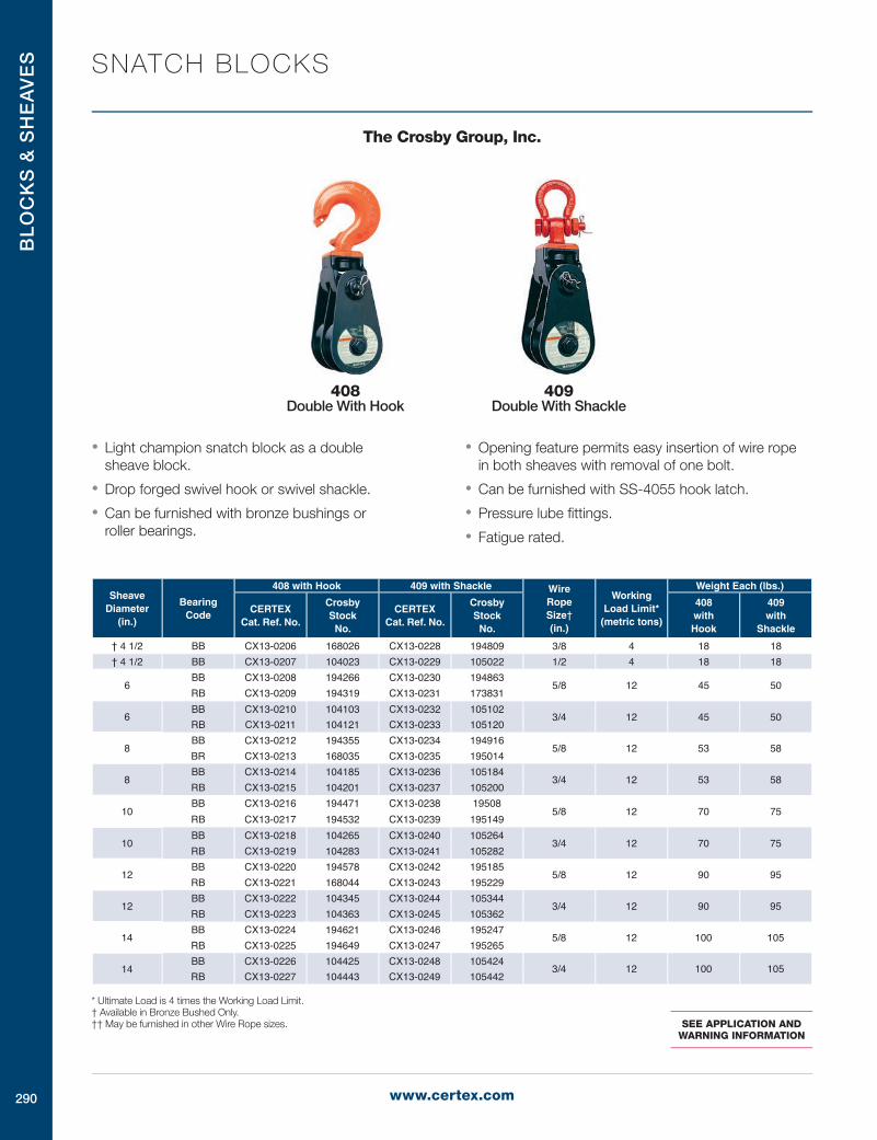
• Light champion snatch block as a double sheave block.
• Drop forged swivel hook or swivel shackle.
• Can be furnished with bronze bushings or roller bearings.
• Opening feature permits easy insertion of wire rope in both sheaves with removal of one bolt.
• Can be furnished with SS-4055 hook latch.
• Pressure lube fittings.
• Fatigue rated.
Sheave Diameter
(in.)
Bearing Code
408 with Hook 409 with Shackle Wire Rope Size† (in.)
Working Load Limit*
(metric tons)
Weight Each (lbs.)
CERTEX Cat. Ref. No.
Crosby Stock
No.
CERTEX Cat. Ref. No.
Crosby Stock
No.
408 with Hook
409 with
Shackle
† 4 1/2 BB CX13-0206 168026 CX13-0228 194809 3/8 4 18 18† 4 1/2 BB CX13-0207 104023 CX13-0229 105022 1/2 4 18 18
6BB CX13-0208 194266 CX13-0230 194863
5/8 12 45 50RB CX13-0209 194319 CX13-0231 173831
6BB CX13-0210 104103 CX13-0232 105102
3/4 12 45 50RB CX13-0211 104121 CX13-0233 105120
8BB CX13-0212 194355 CX13-0234 194916
5/8 12 53 58BR CX13-0213 168035 CX13-0235 195014
8BB CX13-0214 104185 CX13-0236 105184
3/4 12 53 58RB CX13-0215 104201 CX13-0237 105200
10BB CX13-0216 194471 CX13-0238 19508
5/8 12 70 75RB CX13-0217 194532 CX13-0239 195149
10BB CX13-0218 104265 CX13-0240 105264
3/4 12 70 75RB CX13-0219 104283 CX13-0241 105282
12BB CX13-0220 194578 CX13-0242 195185
5/8 12 90 95RB CX13-0221 168044 CX13-0243 195229
12BB CX13-0222 104345 CX13-0244 105344
3/4 12 90 95RB CX13-0223 104363 CX13-0245 105362
14BB CX13-0224 194621 CX13-0246 195247
5/8 12 100 105RB CX13-0225 194649 CX13-0247 195265
14BB CX13-0226 104425 CX13-0248 105424
3/4 12 100 105RB CX13-0227 104443 CX13-0249 105442
* Ultimate Load is 4 times the Working Load Limit.† Available in Bronze Bushed Only.†† May be furnished in other Wire Rope sizes. SEE APPLICATION AND
WARNING INFORMATION
408 Double With Hook
409 Double With Shackle

BL
OC
KS
& S
HE
AV
ES
291
SNATCH BLOCKS
The Crosby Group, Inc.
• Hooks and side plates are forged alloy steel and heat treated.
• Shackles and yokes are forged and heat treated steel.
• Side plates are designed to eliminate possibility of rope jamming.
• Can be furnished with bronze bushings or sealed roller bearings.
• Opening feature permits insertion of rope while block is suspended from gin-pole.
• Can be furnished with SS-4055 hook latch.
• Pressure lube fittings.
• Fatigue rated.
• Hook and shackle assemblies can be interchanged.
Sheave Diameter
(In.)
Bearing Code
420 with Hook 421 with Shackle 406 Tail Board Wire Rope Size† (in.)
Working Load Limit
(metric tons)
Weight Each (lbs.)
CERTEX Cat. Ref. No.
Crosby Stock No.
CERTEX Cat. Ref. No.
Crosby Stock No.
CERTEX Cat. Ref. No.
Crosby Stock No.
420 with Hook
421 with
Shackle
406 Tail
Board
6BB CX13-0250 110025 CX13-0262 110524 CX13-0274 103024
3/4 12 40 48 24RB CX13-0251 110052 CX13-0263 110551 CX13-0275 103042
6BB CX13-0252 169374 CX13-0264 169481 CX13·0276 167973
7/8 12 40 48 24RB CX13-0253 169392 CX13-0265 204120 CX13-0277 167982
8BB CX13-0254 110123 CX13-0268 110622 CX13-0278 103104
3/4 15 51 57 30RB CX13-0255 110150 CX13-0267 110659 CX13-0279 103122
8BB CX13-0256 169418 CX13-0268 169515 CX13-0280 167991
7/8 15 51 57 30RB CX13-0257 169445 CX13-0269 204193 CX13·0281 168008
10BB CX13-0258 204415 CX13-0270 169524 CX13-0282 184179
3/4 15 63 69 42RB CX13-0259 204442 CX13-0271 169542 CX13-0283 184213
10BB CX13-0260 110221 CX13-0272 110720 CX13-0284 103186
7/8 15 63 69 42RB CX13-0261 110258 CX13-0273 110757 CX13·0285 103202
* Ultimate Load is 4 times the Working Load Limit.† May be furnished in other wire rope sizes.
SEE APPLICATION AND WARNING INFORMATION
421 With Shackle
420 With Hook
406 Tail Board
NOTE: When ordering, please specify: Size, block number, hook or shackle, bronze bushed or roller bearing, and wire rope size.

BL
OC
KS
& S
HE
AV
ES
292 www.certex.com
SNATCH BLOCKS
The Crosby Group, Inc.
C-700 Snatch Blocks
• Unique locking device permits disengagement by simply folding hook.
• Formed steel side plates with capacity stamped permanently in place.
• Oil impregnated bronze bushings.
• Can be furnished with SS-4055 hook latch.
* Ultimate Load is 3.5 times the Working Load Limit.
Sheave Diameter
& Block No.
CERTEX Cat. Ref. No.
Crosby Stock
No.
Working Load Limit*
(tons)
Wire Rope Size (in.)
Weight Each (lbs.)
Fitting
6” 10611 CX13-0286 260014 2 1/2 12.00 Swivel Hook8” 10811 CX13-0287 261013 3 5/8 18.60 Swivel Hook
C-700
C-720 Heavy Duty Utility Snatch Block
• Forged steel sheaves, bronze bushings.
• Pressure lube fitting.
• Drop forged steel hook.
• Self-locking style. Locks with hook load.
• Can be furnished with SS-4055 hook latch.
* Ultimate Load is 3.5 times the Working Load Limit.
Sheave Diameter
& Block No.
CERTEX Cat. Ref. No.
Crosby Stock
No.
Working Load Limit*
(tons)
Wire Rope Size (in.)
Weight Each (lbs.)
Fitting
6” 60611 CX13-0288 280010 7 7/8 28.00 Swivel Hook8” 60811 CX13-0289 280038 7 7/8 36.25 Swivel Hook
C-720
C-720 Toggle Block (Tail Board)
• Forged Steel Sheaves, bronze bushing.
• Pressure lube fitting.
* Ultimate Load is 3.5 times the Working Load Limit.
Sheave Diameter
& Block No.
CERTEX Cat. Ref. No.
Crosby Stock
No.
Working Load Limit*
(tons)
Wire Rope Size (in.)
Weight Each (lbs.)
6” 70610 CX13-0290 290018 7 7/8 21.0
C-720
SEE APPLICATION AND WARNING INFORMATION

BL
OC
KS
& S
HE
AV
ES
293
BLOCKS
The Crosby Group, Inc.
Hay Fork Pulleys
161 HF-1
With Swivel Hook
161 HF-2
With Swivel Eye
• One piece pressed steel shells.
• Edges well rounded to prevent chaffing of rope.
• Forged steel eyes and hooks.
• Can be furnished with SS-4055 hook latch.
• Furnished with roller bearings.
• Pressure lube fittings.
• Available Painted or Zinc Plated.
Sheave Diameter
& Block No.
Painted Zinc PlatedWorking
Load Limit* (tons)
Standard Rope Size
(in.)
End Fitting
Weight Each (in.)
CERTEX Cat. Ref. No.
Crosby Stock No.
CERTEX Cat. Ref. No.
Crosby Stock No.
4 1/2" HF-1 CX13-0291 170022 CX13-0300 170594 1 1 1/4 MR Swivel Hook 64 1/2” HF-2 CX13-0292 170086 CX13-0301 170629 1 1 1/4 MR Swivel Eye 64 1/2" HF-3 CX13-0293 170148 CX13-0302 170656 1 1/2 WL Swivel Hook 64 1/2" HF-4 CX13-0294 170200 CX13-0303 170683 1 1/2 WL Swivel Eye 6
8" HF-5 CX13-0295 170264 CX13-0304 170718 2 1/2 WL Swivel Eye 116" HF-11 CX13-0296 170380 CX13-0305 170745 2 1 1/2 MR Swivel Hook 116" HF-12 CX13-0297 170442 CX13-0306 170763 2 1 1/2 MR Swivel Eye 116" HF-13 CX13-0298 170503 CX13-0307 170781 2 5/B WL Swivel Hook 116" HF-14 CX13-0299 170567 CX13-0308 170807 2 5/B WL Swivel Eye 11”
* Ultimate Load is 4 times the Working Load Limit.Rope Code: MR - Manila Rope, WL - Wire Line
SEE APPLICATION AND WARNING INFORMATION

BL
OC
KS
& S
HE
AV
ES
294 www.certex.com
BLOCKS
The Crosby Group, Inc.
Lay Down Blocks • Used to lay down drill pipe.
• All steel construction, steel sheaves mounted on antifriction bearings, grooved for maximum of 3/4” wire line.
• Hook made to fit into end of drill pipe, handy dead end becket for returning block — hooks have handle for disengagement.
171
443
Tong Blocks • Steel sheaves with roller bearings and pressure lubrication.
• Forged steel eyes and hooks.
• Easy opening feature shown available in 8” size only.
* Ultimate Load is 4 times the Working Load Limit.
Sheave Diameter
& Block No.
CERTEX Cat. Ref. No.
Crosby Stock No.
Working Load Limit*
(tons)
Wire Rope Size (in.)
Weight Each (lbs.)
Connection
6” TB-1 CX13-0309 171012 1/2 3/4 11 Swivel Eye8” TB-1 CX13-0310 171058 1 3/4 12 Swivel Eye
10” TB-1 CX13-0311 171101 2 1/2 3/4 30 Swivel Eye12” TB-1 CX13-0312 171156 2 1/2 3/4 35 Swivel Eye
* Ultimate Load is 4 times the Working Load Limit.
Sheave Diameter
& Block No.
CERTEX Cat. Ref. No.
Crosby Stock No.
Working Load Limit*
(tons)
Wire Rope Size (in.)
Weight Each (lbs.)
Type Block
4 1/2” 443 CX13-0313 171414 1/4 1/2 12 Regular6” 443 CX13-0314 171432 1/4 3/4 17 Regular
SEE APPLICATION AND WARNING INFORMATION

BL
OC
KS
& S
HE
AV
ES
295
MCKISSICK® UTIL ITY CRANE BLOCKS
The Crosby Group, Inc.
380 Series Hook Blocks
SEE APPLICATION AND WARNING INFORMATION
• Wide range of product available.
• Capacity: 5 to 300 Tons - Larger Models Available.
• Sheave Sizes: 10” to 30”.
• Wireline Sizes: 7/16” to 1-3/8”.
• Manufactured by an ISO 9001 and API Q1 certified facility.
• All single point shank hooks are genuine Crosby®, forged alloy steel, Quenched and Tempered, and have the patented QUICCHECK® markings (Duplex hooks are available on all sizes).
• All 380 Blocks are furnished standard with Roller Bearings.
• Reeving Guide Standard – All Models.
• Blocks thru 25 tons use 319N style hooks with S-4320 latches.
• Sheaves lubrication through center pin – separate lube channel to each bearing.
• Sheave fully protected by side plates.
• Dual action hook (swings and rotates).
• Repair parts available through worldwide distribution network.
• Design Factor of 4 to 1 (unless otherwise noted).
• All 380 blocks 16” and larger are furnished with McKissick® Roll-Forged sheaves with flame hardened grooves.
• “Look for the Orange Hook … the mark of genuine McKissick® quality”.
381 Single
382 Double
380 Series Hook Block
Options Available• Bronze Bushed Sheaves
• Duplex Hooks
• Swivel Tee and Shackle Assemblies
• Sheave Shrouds
• Anti Rotation Hook - Locking Device
• Plate Steel Cheek Weights
• Third party testing with Certification available upon request.
Wireline Size (in.)
Dimensions (in.)
Recommended Wedge Socket
T Thickness
U Hole
Diameter
McKissick® US-422 / US-422T Utility Socket
Stock No. Size
7/16 1.00 1.28 1044309+ US4 7/161/2 1.00 1.28 1044318+ US4 1/2
9/16 1.00 1.28 1044336+ US5 9/165/8 1.00 1.28 1044345+ US5 5/83/4 1.25 1.66 1044363+ US6 3/47/8 1.25 1.66 1038580 US7 7/81 1.25 1.66 1044417+ US8 1
1-1/8 1.75 2.56 1044426+ US10 1-1/81-1/4 1.75 2.56 1044435+ US10 1-1/4
Dead End Chart (Double, Triple, & Quad Sheave Blocks*)
+ US-422T Terminator Style.
The patented McKissick Split-Nut® is the standard retention system for standard crane blocks up to 100 Tons.

BL
OC
KS
& S
HE
AV
ES
296 www.certex.com
MCKISSICK® EASY REEVE® CRANE BLOCKS
The Crosby Group, Inc.
380 Series Easy Reeve® Hook Blocks • Wide range of products available.
• Capacity: 5 to 80 Tons - Larger Models Available.
• Sheave Sizes: 10” to 20”.
• Wireline Sizes: 7/16” to 1-1/4”.
• All single point shank hooks are genuine Crosby®, forged alloy steel, Quenched and Tempered, and have the patented QUICCHECK® markings (Duplex hooks are available on most sizes).
• Design factor of 4 to 1 (unless otherwise noted).
• All Easy Reeve® Blocks are furnished standard with Roller Bearings.
• Reeving Guides Standard – All Models.
• Blocks thru 25 Tons use 319N hooks with S-4320 latches.
• Heavy Duty Positive Locking (PL) Latch – Models: 30 Tons and larger.
• Sheave lubrication through center pin - separate lube channel to each bearing.
• Sheaves fully protected by side plates.
• Dual action hook (swings and rotates).
• Repair parts available through worldwide distribution network.
• All Easy Reeve® blocks 16” and larger are furnished with McKissick® Roll-Forged sheaves with flame hardened grooves.
• Manufactured by an ISO 9001 and API Q1 certified facility.
• “Look for the Orange Hook … the mark of genuine McKissick® quality”.
Options Available• Duplex Hooks
• Swivel Tee and Shackle Assemblies
• Sheave Shrouds
• Anti-Rotation Hook-Locking Device
• Plate Steel Cheek Weights
• Third party testing with Certification available upon request.
Center “Dead End” to promote better block travel under various reeving configurations.
Sheave Guards that open to allow block reeving without removing the rope end fitting.
Flat Bottom side plate for self standing during reeving process.
Forged Crosby® alloy steel hooks with patented QUIC-CHECK®
markings and Heavy Duty positive locking hook latch.SEE APPLICATION AND WARNING INFORMATION
The patented McKissick Split-Nut® is the standard retention system for standard crane blocks up to 100 Tons.
380 Series Easy Reeve® Hook Block

BL
OC
KS
& S
HE
AV
ES
297
BLOCKS
The Crosby Group, Inc.
McKissick Series 680 Construction Blocks
• Wide Range of product available:
• Capacity: 5 to 65 tons - Larger models available.
• Sheave sizes: 6” to 24” O.D.
• Wire Line Sizes: 3/8” to 1-1/4”
• Equipped with genuine Crosby® forged steel, Quenched and Tempered shackles that contain the patented QUIC-CHECK® markings.
• Design Factor of 4 to 1.
• Manufactured by an ISO 9001 and API Q1 Certified facility.
• All 680 Series Blocks are furnished standard with Bronze Bushings.
• All 680 blocks 16” and larger, are furnished with McKissick® Roll Forged® sheaves with flame hardened grooves.
• Sheaves are lubricated through center pin, with a separate lube channel to each sheave.
Options Available• Roller bearing sheaves
• Hanger & Bolt only models available
• Third party testing with certification
• Galvanized finish - Most models
With Shackle With Hanger Bolt Only

BL
OC
KS
& S
HE
AV
ES
298 www.certex.com
BLOCKS
The Crosby Group, Inc.
McKissick Series 680 Construction Blocks
“P” FITTING — Blocks with Bolt Only 5 Tons Section Only
CERTEX Cat. Ref.
No.
McKissick Model
No.
Inquiry Stock
No.
Working Load Limit
(tons)
No. of Sheaves
Sheave Diameter
(in.)
Blocks with Bolt Only Dimensions Weight Each (lbs.)A B C D E F G H I J K X
CX13-0800 C5S6BP 2101000 5 1 6 12.12 1.62 1.78 — 2.28 6.12 — — — 2.00 1.25 — 19CX13-0801 C5S8BP 2101002 5 1 8 14.00 1.62 1.78 — 2.28 8.12 — — — 2.00 1.25 — 31CX13-0802 C5D6BP 2101010 5 2 6 14.75 1.62 3.81 1.06 4.31 6.12 .63 .69 .84 1.79 1.25 2.03 33CX13-0803 C5D8BP 2101012 5 2 8 16.62 1.62 3.81 1.06 4.31 6.12 .63 .69 .84 1.79 1.25 2.03 54CX13-0804 C5T6BP 2101020 5 3 6 14.75 1.62 5.84 1.06 6.34 6.12 .63 .69 .84 1.79 1.25 2.03 45CX13-0805 C5T8BP 2101022 5 3 8 16.62 1.62 5.84 1.06 6.34 8.12 .63 .69 .84 1.79 1.25 2.03 75
Other Sizes Available by Request.
“H” FITTING — Blocks with Hangers 5 Tons Section Only
CERTEX Cat.Ref.
No.
McKissick Model
No.
Inquiry Stock
No.
Working Load Limit
(tons)
No. of Sheaves
Sheave Diam (in.)
Blocks with Hangers - Dimensions Weight Each (lbs.)A E F G H I L M N O P Q X
CX13-0806 C5S6BH 2102000 5 1 6 15.00 2.28 6.12 — — — 1.63 1.25 1.06 1.16 3.25 1.86 — 22CX13-0807 C5S8BH 2102002 5 1 8 16.88 2.28 8.12 — — — 1.63 1.25 1.06 1.16 3.25 1.86 — 34CX13-0808 C5D6BH 2102010 5 2 6 17.62 4.31 6.12 .63 .69 .84 1.63 1.25 1.06 1.16 3.25 2.25 2.03 37CX13-0809 C5D8BH 2102012 5 2 8 19.50 4.31 8.12 .63 .69 .84 1.63 1.25 1.06 1.16 3.25 2.25 2.03 58CX13-0810 C5T6BH 2102020 5 3 6 17.62 6.34 6.12 .63 .69 .84 1.63 1.25 1.06 1.16 3.25 2.25 2.03 51CX13-0811 C5T8BH 2102022 5 3 8 19.50 6.34 8.12 .63 .69 .84 1.63 1.25 1.06 1.16 3.25 2.25 2.03 81 Other Sizes Available by Request.
“S” FITTING — Blocks with Hanger and Shackle 5 Tons Section Only
CERTEX Cat. Ref.
No.
McKisset Model No.
Inquiry Stock No.
Working Load Limit
(tons)
No. of Sheaves
Sheave Diam. (in.)
Blocks with Hangers and Shackle - Dimensions Weight Each (lbs.)A E F G H I S T U V W X
CX13-0812 C5S6BS 2103000 5 1 6 18.56 2.28 6.12 — — — 3.81 2.56 1.14 .88 .97 — 25CX13-0813 C5S8BS 2103002 5 1 8 20.44 2.28 8.12 — — — 3.81 2.56 1.14 .88 .97 — 37CX13-0814 C5D6BS 2103010 5 2 6 21.19 4.31 6.12 .63 .69 .84 3.81 2.56 1.14 .88 .97 2.03 40CX13-0815 C5D8BS 2103012 5 2 8 23.06 4.31 8.12 .63 .69 .84 3.81 2.56 1.14 .88 .97 2.03 61CX13-0816 C5T6BS 2103020 5 3 6 21.19 6.34 6.12 .63 .69 .84 3.81 2.56 1.14 .88 .97 2.03 54CX13-0817 C5T8BS 2103022 5 3 8 23.06 6.34 8.12 .63 .69 .84 3.81 2.56 1.14 .88 .97 2.03 84 Other Sizes Available by Request.

BL
OC
KS
& S
HE
AV
ES
299
BLOCKS
The Crosby Group, Inc.
Gin Blocks for Manila Rope
T-350-C
For light hoisting by Roofers and Contractors
Furnished with drop forged swivel latch hooks.
Can be furnished with SS-4055 hook latch.
Block
Size
(in.)
Fitting
T-350-C Painted T-350-R Painted T-350-B Painted Sheave Size (in.) Manila
Rope
Size
(in.)
Working
Load
Limit *
(lbs.)
Weight
Each
(lbs.)
CERTEX
Cat. Ref.
No.
Crosby
Stock
No.
CERTEX
Cat. Ref.
No.
Crosby
Stock
No.
CERTEX
Cat. Ref.
No.
Crosby
Stock
No.
Outside
Diameter
Rim
Thickness
Bearing
Diameter
8 T CX13-0359 710001 CX13-0363 710207 CX13-0367 710403 8.00 1.25 .75 7/8 1000 9.0
10 T CX13-0360 710029 CX13-0364 710225 CX13-0368 710421 10.00 1.25 .88 1 1000 9.8
12 T CX13-0361 710047 CX13-0365 710243 CX13-0369 710449 12.00 1.38 .88 1 1000 12.7 * Ultimate Load is 3 times the Working Load Limit.Bearing Code: C — Common Iron, R — Roller, B — Self-Lubricating Bronze Bushed
Wood Blocks for Manila Rope
HS-21-B Single
(available in N & S)
Block Size (in.)
Fitting
Single Sheave Double Sheave Triple Sheave
21 B Galv. 22 B Galv. 23 B Galv.
CERTEX Cat. Ref. No.
Crosby Stock No.
CERTEX Cat. Ref. No.
Crosby Stock No.
CERTEX Cat. Ref. No.
Crosby Stock No.
3 HS CX13-0376 603813 CX13-0402 604616 CX13-0426 6054104 HS CX13-0377 603831 CX13-0403 604634 CX13-0427 6054385 HS CX13-0378 603859 CX13-0404 604652 CX13-0428 6054566 HS CX13-0379 603877 CX13-0405 604670 CX13-0429 6054748 HS CX13-0380 603911 CX13-0406 604714 CX13-0430 6055173 N CX13-0381 606419 CX13-0407 606810 CX13-0431 6072124 N CX13-0382 606437 CX13-0408 606838 CX13-0432 6072305 N CX13-0383 606455 CX13-0409 606856 CX13-0433 6072586 N CX13-0384 606473 CX13-0410 606874 CX13-0434 6072768 N CX13-0385 606516 CX13-0411 606918 CX13-0435 6073103 S CX13-0386 610011 CX13-0412 611617 CX13-0436 6132144 S CX13-0387 610039 CX13-0413 611635 CX13-0437 6132325 S CX13-0388 610057 CX13-0414 611653 CX13-0438 6132506 S CX13-0389 610075 CX13-0415 611671 CX13-0439 6132788 S CX13-0390 610119 CX13-0416 611715 CX13-0440 613312
Block Size (in.)
Sheave Diameter (in.) Manila
Rope Size (in.)
Working Load Limit* (lbs.)
Weight Each (lbs.)
Outside Diam.
Rim Thickness
Center Pin Diam.
21 Single
22 Double
23 Triple
21 Single
22 Double
23 Triple
3 1.75 .50 .38 3J8 500 800 1200 1.00 1.75 2.504 2.25 .63 .38 112 1000 1400 1800 1.75 3.00 4.005 3.00 .75 .38 518 1200 1800 2400 3.25 5.60 6.506 3.50 1.00 .50 314 1800 2500 3200 5.00 8.50 11.508 4.75 1.13 .63 7/8-1 2800 3800 4800 9.00 14.00 21.50
*Ultimate Load is 4 times the Working Load Limit. Note: We furnish beckets on all blocks.
SEE APPLICATION AND WARNING INFORMATION

BL
OC
KS
& S
HE
AV
ES
300 www.certex.com
OVERHAUL BALLS
The Crosby Group, Inc.
UB500 Series Top Swiveling Overhaul Balls
* Hook is New S-320N style. Replacement latch kit is S-4320. PL latch and S-4055 latch will not fit.
S320 or S320N Eye Hook
S316A SHUR-LOC® Eye Hook
• The top swivel design on the UB500 assures the ball remains stationary if the wire line spins.
• The swivel incorporates a sealed roller thrust bearing together with a grease fitting for easy lubrication.
• Each ball can be equipped with the new McKissick US422 Wedge & Socket which can be easily adjusted to fit various sizes of wire rope by changing the wedge (Ensure that correct wedge is used for selected wire rope size).
• Design Factor 4:1
• All hooks used on UB500 Overhaul Balls (S320, S320N & S316A) are forged from alloy steel. The S320 and S320N hooks come complete with latches.
• Sizes 4 tons through 10 tons available with Crosby’s S316A “Positive Locking” SHUR-LOC® hook which may be used for lifting personnel. Meets OSHA Rule 1926.550 (g).
• The S320 hook (PL latch) and the S320N hook (S4320 latch), with the proper latch attached, may be used for personnel lifting when secured with proper device (Bolt, nut and pin for the PL latch; Cotter pin for the S4320 latch). Meets OSHA Rule 1926.550 (g).
Key to McKissick® UB500 Utility Overhaul Ball Model Numbers
MB 4 T 35 EMcKissick®
Utility Overhaul Ball
Working Load Limit
(Tons)
Swivel Style
Ball only Weight
Hook Style
T = Top E = 320 or 320N Eye Hook
NS = Non S = SHUR-LOC® Eye Hook
Overhaul Ball Assembly Optional US-422 Wedge & Socket AssemblyMcKissick UB500 UB500 “E” Eye Hook UB500 “S” SHUR-LOC® Working
Load Limit (tons)
Weight Each (lbs.)
Wire Rope Size (in.)
US-422 Weight Each (lbs.)
CERTEX Cat. Ref. No.
McKissick Model No.
CERTEX Cat. Ref. No.
Crosby Stock No.
CERTEX Cat. Ref. No.
Crosby Stock No.
Model No.CERTEX
Cat. Ref. No.Crosby
Stock No.CX13-0500 MB4T35 CX13-0531 1036000* CX13-0562 1036005 4 58 3/8 US4 CX13-0575 1038499 4.6CX13-0501 MB4T85 CX13-0532 1036009* CX13-0563 1036018 4 102 7/16 US4 CX13-0576 1038503 4.6CX13-0502 MB4T150 CX13-0533 1036027* CX13-0564 1036032 4 162 1/2 US4 CX13-0577 1038508 4.6CX13-0503 MB4T200 CX13-0534 1036036* CX13-0565 1036041 4 201 1/2 US5 CX13-0578 1038517 8.5CX13-0504 MB7T85 CX13-0535 1036045* CX13-0566 1036050 7 109 9/16 US5 CX13-0579 1038526 8.5CX13-0505 MB7T150 CX13-0536 1036054* CX13-0567 1036063 7 170 5/8 US5 CX13-0580 1038535 8.5CX13-0506 MB7T200 CX13-0537 1036072* CX13-0568 1036077 7 210 5/8 US6 CX13-0581 1038544 9.4CX13-0507 MB7T285 CX13-0538 1036081* CX13-0569 1036086 7 321 3/4 US6 CX13-0582 1038533 9.4CX13-0508 MB10T150 CX13-0539 1036090* CX13-0570 1036095 10 216CX13-0509 MB10T200 CX13-0540 1036099* CX13-0571 1036108 10 260CX13-0510 MB10T285 CX13-0541 1036117* CX13-0572 1036122 10 365 5/8 US6 CX13-0583 1038544 9.4CX13-0511 MB10T350 CX13-0542 1036126* CX13-0573 1036131 10 403 3/4 US6 CX13-0584 1038553 9.4CX13-0512 MB10T650 CX13-0543 1036135* CX13-0574 1036140 10 718 7/8 US8 CX13-0585 1038598 20.8CX13-0513 MB12T150 CX13-0544 1036144* — — 12 216 1 US8 CX13-0586 1038607 20.8CX13-0514 MB12T200 CX13-0545 1036153* — — 12 258 1 1/18 US10 CX13-0587 1038616 46.5CX13-0515 MB12T285 CX13-0546 1036171* — — 12 365 1 1/4 US10 CX13-0588 1038625 46.5CX13-0516 MB12T350 CX13-0547 1036180* — — 12 403CX13-0517 MB12T650 CX13-0548 1036189* — — 12 718CX13-0518 MB15T200 CX13-0549 1036198* — — 15 298CX13-0519 MB15T350 CX13-0550 1036207* — — 15 456CX13-0520 MB15T650 CX13-0551 1036216* — — 15 753CX13-0521 MB15T1150 CX13-0552 1036225* — — 15 1311 5/8 US8A CX13-0589 1038562 17.5CX13-0522 MB30T200 CX13-0553 1036234* — — 20 298 3/4 US8A CX13-0590 1038571 17.5CX13-0523 MB20T350 CX13-0554 1036243* — — 20 456 7/8 US8 CX13-0591 1038598 20.8CX13-0524 MB20T650 CX13-0555 1036252* — — 20 753 1 US8 CX13-0592 1038607 20.8CX13-0525 MB20T1150 CX13-0556 1036261* — — 20 1311 1 1/18 US10 CX13-0593 1038616 46.5CX13-0526 MB25T350 CX13-0557 1036270 — — 25 533 1 1/4 US10 CX13-0594 1038625 46.5CX13-0527 MB25T650 CX13-0558 1036279 — — 25 865CX13-0528 MB25T1150 CX13-0559 1036288 — — 25 1421CX13-0529 MB30T650 CX13-0560 1036297 — — 30 865CX13-0530 MB30T1150 CX13-0561 1036306 — — 30 1421

BL
OC
KS
& S
HE
AV
ES
301
OVERHAUL BALLS
The Crosby Group, Inc.
UB500 Series Top Swiveling Overhaul Balls
• 4 ton through 20 ton models are New 320-N Eye HooksStandard Crosby S-5 Thrust Bearing style swivels can not be used with UB500 Overhaul balls.
Putting Certainty Into Everything We Make.
CERTEX provides the rope slings, rope terminations and other tailor-made assemblies that allow our customers to tackle their lifting challenges with confidence. At CERTEX, every custom operation from cutting rope to applying hooks and shackles to making the most demanding sling, carries out the same assurance of safety. Safety is built into our products at every stage of our fabricating process. A CERTEX-made product can be trusted because it starts with components that meet
the highest possible standards of safety and reliability. Using these quality components, the CERTEX expertise in lifting is applied in our own rigging shops: the result is customized lifting equipment that will perform in the most critical applications where lives and property depend on it. With experienced people and machinery to produce the lifting equipment that our customers specify, CERTEX companies everywhere are committed to the complete reliability of every product that we make.

BL
OC
KS
& S
HE
AV
ES
302 www.certex.com
OVERHAUL BALLS
The Crosby Group, Inc.
UB500 Series Top Swiveling Overhaul Balls
UB500 Top Swivel Overhaul Balls with 320 Eye Hooks
CERTEX Cat. Ref. No.
UB500 McKissick Model No.
CERTEX Cat. Ref. No.
UB500 “E”
Eye Hook Crosby Stock No.
Deformation Indicator
AA
Dimensions (in.)
A B C D E F G H I J
CX13-0500 MB4T35 CX13-0531 1036000 2.5 20.09 17.27 7.50 1.36 1.44 1.12 1.88 1.38 .88 1.31CX13-0501 MB4T85 CX13-0532 1036009 2.5 20.98 18.16 9.25 1.36 1.44 1.12 1.88 1.38 .88 1.31CX13-0502 MB4T150 CX13-0533 1036027 2.5 21.98 19.16 11.25 1.36 1.44 1.12 1.88 1.38 .88 1.31CX13-0503 MB4T200 CX13-0534 1036036 2.5 22.35 19.53 12.50 1.36 1.44 1.12 1.88 1.38 .88 1.31CX13-0504 MB7T85 CX13-0535 1036045 3.0 23.18 20.36 9.25 1.61 1.81 1.38 1.88 1.38 .88 1.31CX13-0505 MB7T150 CX13-0536 1036054 3.0 24.56 21.36 11.25 1.61 1.81 1.38 1.88 1.38 .88 1.31CX13-0506 MB7T200 CX13-0537 1036072 3.0 24.89 21.71 12.50 1.61 1.81 1.38 1.88 1.38 .88 1.31CX13-0507 MB7T285 CX13-0538 1036081 3.0 25.86 22.67 13.88 1.61 1.81 1.38 1.88 1.38 .88 1.31CX13-0508 MB10T150 CX13-0539 1036090 4.0 31.44 27.19 11.25 2.08 2.25 1.62 2.75 2.00 1.25 1.78CX13-0509 MB10T200 CX13-0540 1036099 4.0 31.81 27.56 12.50 2.08 2.25 1.62 2.75 2.00 1.25 1.78CX13-0510 MB10T285 CX13-0541 1036117 4.0 32.75 28.50 13.88 2.08 2.25 1.62 2.75 2.00 1.25 1.78CX13-0511 MB10T350 CX13-0542 1036126 4.0 33.31 29.06 15.00 2.08 2.25 1.62 2.75 2.00 1.25 1.78CX13-0512 MB10T650 CX13-0543 1036135 4.0 34.79 30.54 17.94 2.08 2.25 1.62 2.75 2.00 1.25 1.78CX13-0513 MB12T150 CX13-0544 1036144 4.0 31.44 27.19 11.25 2.08 2.25 1.62 2.75 2.00 1.25 1.78CX13-0514 MB12T200 CX13-0545 1036153 4.0 31.81 27.56 12.50 2.08 2.25 1.62 2.75 2.00 1.25 1.78CX13-0515 MB12T285 CX13-0546 1036171 4.0 32.75 28.50 13.88 2.08 2.25 1.62 2.75 2.00 1.25 1.78CX13-0516 MB12T350 CX13-0547 1036180 4.0 33.31 29.06 15.00 2.08 2.25 1.62 2.75 2.00 1.25 1.78CX13-0517 MB12T650 CX13-0548 1036189 4.0 35.79 30.54 17.94 2.08 2.25 1.62 2.75 2.00 1.25 1.78CX13-0518 MB15T200 CX13-0549 1036198 5.0 37.59 32.59 12.50 3.02 3.00 2.38 2.38 2.00 1.25 1.78CX13-0519 MB15T350 CX13-0550 1036207 5.0 38.81 33.81 15.00 3.02 3.00 2.38 2.38 2.00 1.25 1.78CX13-0520 MB15T850 CX13-0551 1036216 5.0 40.22 35.22 17.94 3.02 3.00 2.38 2.38 2.00 1.25 1.78CX13-0521 MB15T1150 CX13-0552 1036225 5.0 42.22 37.22 21.62 3.02 3.00 2.38 2.38 2.00 1.25 1.78CX13-0522 MB20T200 CX13-0553 1036234 5.0 37.59 32.59 12.50 3.02 3.00 2.38 2.38 2.00 1.25 1.78CX13-0523 MB20T350 CX13-0554 1036243 5.0 38.81 33.81 15.00 3.02 3.00 2.38 2.38 2.00 1.25 1.78CX13-0524 MB20T650 CX13-0555 1036252 5.0 40.22 35.22 17.94 3.02 3.00 2.38 2.38 2.00 1.25 1.78CX13-0525 MB20T1150 CX13-0556 1036261 5.0 42.22 37.22 21.62 3.02 3.00 2.38 2.38 2.00 1.25 1.78CX13-0526 MB25T350 CX13-0557 1036270 6.5 47.18 40.18 15.00 3.00 3.62 3.00 3.31 2.75 1.75 1.78CX13-0527 MB25T650 CX13-0558 1036279 6.5 49.12 42.75 17.94 3.00 3.62 3.00 3.31 2.75 1.75 1.78CX13-0528 MB25T1150 CX13-0559 1036288 6.5 51.06 44.69 21.62 3.00 3.62 3.00 3.31 2.75 1.75 1.78CX13-0529 MB30T850 CX13-0560 1036297 6.5 49.12 42.75 17.94 3.00 3.62 3.00 3.31 2.75 1.75 1.78CX13-0530 MB30T1150 CX13-0561 1036306 6.5 51.06 44.69 21.62 3.00 3.62 3.00 3.31 2.75 1.75 1.78
UB500 Top Swivel Overhaul Balls with SHUR-LOC® Positive Locking Hooks
CERTEX Cat. Ref. No.
UB500 McKissick Model No.
CERTEX Cat. Ref. No.
UB500 “S”
SHUR-LOC® Crosby Stock No.
Dimensions (in.)
A B C D E F G H I J
CX13-0500 MB4T35 CX13-0562 1036005 20.66 18.18 7.50 1.87 1.15 .94 1.88 1.38 .88 1.31CX13-0501 MB4T85 CX13-0563 1036018 21.55 19.05 9.25 1.87 1.15 .94 1.88 1.38 .88 1.31CX13-0502 MB4T150 CX13-0564 1036032 22.55 20.05 11.25 1.87 1.15 .94 1.88 1.38 .88 1.31CX13-0503 MB4T200 CX13-0565 1036041 22.92 20.42 12.50 1.87 1.15 .94 1.88 1.38 .88 1.31CX13-0504 MB7T85 CX13-0566 1036050 23.90 21.30 9.25 2.11 1.66 1.16 1.88 1.38 .88 1.31CX13-0505 MB7T150 CX13-0567 1036063 25.28 22.30 11.25 2.11 1.66 1.16 1.88 1.38 .88 1.31CX13-0506 MB7T200 CX13-0568 1036077 25.61 22.65 12.50 2.11 1.66 1.16 1.88 1.38 .88 1.31CX13-0507 MB7T285 CX13-0569 1036086 26.58 23.61 13.88 2.11 1.66 1.16 1.88 1.38 .88 1.31CX13-0508 MB10T150 CX13-0570 1036095 31.24 27.19 11.25 2.49 2.06 1.50 2.75 2.00 1.25 1.78CX13-0509 MB10T200 CX13-0571 1036108 31.61 27.56 12.50 2.49 2.06 1.50 2.75 2.00 1.25 1.78CX13-0510 MB10T285 CX13-0572 1036122 32.55 28.50 13.88 2.49 2.06 1.50 2.75 2.00 1.25 1.78CX13-0511 MB10T350 CX13-0573 1036131 33.11 29.06 15.00 2.49 2.06 1.50 2.75 2.00 1.25 1.78CX13-0512 MB10TB50 CX13-0574 1036140 34.59 30.54 17.94 2.49 2.06 1.50 2.75 2.00 1.25 1.78

BL
OC
KS
& S
HE
AV
ES
303
SHEAVES
The Crosby Group, Inc.
Ordering InformationMcKissick sheaves come in a variety of sizes to suit your specific applications. Check the tables for the size, bearing style and price that best fits your application. For applications that require unique specifications Crosby can make minor modifications to many of the sheaves listed at a reasonable charge. We can also custom design and manufacture sheaves to your exact requirements. For special requirements or custom designed sheaves, furnish the following important information:
• Wireline Size
• Shaft Diameter
• Weight Requirements
• Hub Diameter
• Bore Finished
• Nominal Outside Diameter
• Hub Width
• Rim Width
• Nominal Tread Diameter
• Other Special Requirements
Roll Forged Sheave Features
• Unique upset roll forging process provides a thicker groove section for extra strength.
• Stepped Hubs are precisely centered and mechanically locked in place.
• Wireline grooves on sheave diameters of 14” and larger are flamed hardened for extra wear resistance.
• All sheaves have solid steel webs with holes for easy handling.
• Sheave weights can be made heavier or lighter than shown to fit your specific application.
• For more information ask for our special brochure describing the complete roll forging process.