TAC (TRUE AIR CURTAIN MODELS) - WebstaurantStore · TAC (TRUE AIR CURTAIN MODELS) ... refrigeration...
33
............ www.truemfg.com ............ INSTALLATION MANUAL FOR AIR CURTAIN MODELS TAC (TRUE AIR CURTAIN MODELS) CONGRATULATIONS! You have just purchased the finest commercial refrigeration available. You can expect many years of trouble-free operation. TRUE FOOD SERVICE EQUIPMENT, INC. 2001 East Terra Lane • O’Fallon, Missouri 63366-4434 (636) 240-2400 • FAX (636) 272-2408 • INT’L FAX (636) 272-7546 • (800) 325-6152 Parts Department (800) 424-TRUE • Parts Department FAX# (636) 272-9471 TABLE OF CONTENTS Safety Information TAC-48 Installation Tips –––––––––––––––––––– 1 Safety Precautions –––––––––––––––––––––––– 2 Proper Disposal ––––––––––––––––––––––––––– 3 Connecting Electricity ––––––––––––––––––––– 4 Adapter Plugs –––––––––––––––––––––––––––– 4 Installation / Operation Instructions Ownership ––––––––––––––––––––––––––––––– 5 Required Tools ––––––––––––––––––––––––––– 5 Uncrating –––––––––––––––––––––––––––––––– 5 Locating ––––––––––––––––––––––––––––––––– 6 Installation of Leg/Castors ––––––––––––––––––– 7 Electrical Instructions –––––––––––––––––––––– 7 Leveling Cabinet –––––––––––––––––––––––––– 7 Conductors and Circuits–––––––––––––––––––– 8 Start-up & Light Switch Location –––––––––––– 9 Mechanical Temperature Control Adjustments ––––––––––––––––––––––––––– 10-11 Defrost Timer Instructions ––––––––––––––––– 12 Digital Temperature Control Adjustments –– 13-14 LAE Temperature Control –––––––––––––– 15-23 Remote Unit Installation ––––––––––––––––––– 24 Shelving & Flavor Strip Installation ––––––– 25-26 Maintenance, Care & Cleaning Cleaning Condenser Coil ––––––––––––––– 27-28 Stainless Steel Equipment Care & Cleaning 29-30 Light Bulb Replacement ––––––––––––––––––– 30 Warranty (U.S.A. & CANADA ONLY!) –––––––– 31 #897010 *Spanish, German, French, Dutch, and Polish version included. TAC-30 TAC-36 TAC-48 TAC-48GS TAC-72RC
-
Upload
vuongtuyen -
Category
Documents
-
view
222 -
download
0
Transcript of TAC (TRUE AIR CURTAIN MODELS) - WebstaurantStore · TAC (TRUE AIR CURTAIN MODELS) ... refrigeration...
............ www.truemfg.com ............
INSTALLATION MANUAL FOR AIR CURTAIN MODELS
TAC (TRUE AIR CURTAIN MODELS)
CONGRATULATIONS! You have just purchased the finest commercial
refrigeration available. You can expect many years of trouble-free operation.
TRUE FOOD SERVICE EQUIPMENT, INC.2001 East Terra Lane • O’Fallon, Missouri 63366-4434
(636) 240-2400 • FAX (636) 272-2408 • INT’L FAX (636) 272-7546 • (800) 325-6152Parts Department (800) 424-TRUE • Parts Department FAX# (636) 272-9471
TABLE OF CONTENTS
Safety InformationTAC-48 Installation Tips –––––––––––––––––––– 1Safety Precautions –––––––––––––––––––––––– 2Proper Disposal ––––––––––––––––––––––––––– 3Connecting Electricity ––––––––––––––––––––– 4Adapter Plugs –––––––––––––––––––––––––––– 4
Installation / Operation InstructionsOwnership ––––––––––––––––––––––––––––––– 5Required Tools ––––––––––––––––––––––––––– 5Uncrating –––––––––––––––––––––––––––––––– 5Locating ––––––––––––––––––––––––––––––––– 6Installation of Leg/Castors ––––––––––––––––––– 7 Electrical Instructions –––––––––––––––––––––– 7Leveling Cabinet –––––––––––––––––––––––––– 7Conductors and Circuits –––––––––––––––––––– 8Start-up & Light Switch Location –––––––––––– 9Mechanical Temperature Control Adjustments ––––––––––––––––––––––––––– 10-11Defrost Timer Instructions ––––––––––––––––– 12Digital Temperature Control Adjustments –– 13-14LAE Temperature Control –––––––––––––– 15-23Remote Unit Installation ––––––––––––––––––– 24Shelving & Flavor Strip Installation ––––––– 25-26
Maintenance, Care & CleaningCleaning Condenser Coil ––––––––––––––– 27-28Stainless Steel Equipment Care & Cleaning 29-30Light Bulb Replacement ––––––––––––––––––– 30Warranty (U.S.A. & CANADA ONLY!) –––––––– 31
#897010
*Spanish, German, French, Dutch, and Polish version included.
TAC-30
TAC-36
TAC-48
TAC-48GS
TAC-72RC

............ www.truemfg.com ............
True Food Service Equipment, Inc.

............ www.truemfg.com ............
True Food Service Equipment, Inc.
1 1
............ www.truemfg.com ............
True Food Service Equipment, Inc.
2 2
SAFETY INFORMATION
• ThisrefrigeratormustbeproperlyinstalledandlocatedinaccordancewiththeInstallationInstructionsbeforeitisused.
• Donotallowchildrentoclimb,standorhangontheshelvesintherefrigerator.Theycoulddamagetherefrigeratorandseriouslyinjurethemselves.
• Donottouchthecoldsurfacesintherefrigeratorcompartmentwhenhandsaredamporwet.Skinmaysticktotheseextremelycoldsurfaces.
• Donotstoreorusegasolineorotherflammablevaporsandliquidsinthevicinityofthisoranyotherappliance.
• Keepfingersoutofthe“pinchpoint”areas;clearancesbetweenthedoorsandbetweenthedoorsandcabinetarenecessarilysmall;becarefulclosingdoorswhenchildrenareinthearea.
NOTE We strongly recommend that any servicing be performed by a qualified individual.• Unplugtherefrigeratorbeforecleaningand makingrepairs.• Settingtemperaturecontrolstothe0positiondoes
notremovepower.
• Danger-Riskoffireorexplosion.Flammablerefrigerantused.Donotusemechanicaldevicestodefrostrefrigerator.Donotpuncturerefrigeranttubing.
• Danger-Riskoffireorexplosion.Flammablerefrigerantused.Toberepairedonlybytrainedservicepersonnel.Donotpuncturerefrigeranttubing.
• Caution-Riskoffireorexplosion.Flammablerefrigerantused.Consultrepairmanual/owner’sguidebeforeattemptingtoservicethisproduct.Allsafetyprecautionsmustbefollowed.
• Caution-Riskoffireorexplosion.Disposeofproperlyinaccordancewithfederalorlocalregulations.Flammablerefrigerantused.
• Caution-Riskoffireorexplosionduetopunctureofrefrigeranttubing;followhandlinginstructionscarefully.Flammablerefrigerantused.
• Caution-Keepclearofobstructionallventilationopeningsintheapplianceenclosureorinthestructureforbuilding-in.
WARNING!Use this appliance for its intended purpose as described in this Owner Manual.
TO LOCATE REFRIGERANT TYPE, SEE SERIAL LABEL INSIDE CABINET.
This cabinet may contain fluorinated greenhouse gas covered by the Kyoto Protocol (please refer to cabinet’s inner label for type and volume, GWP of 134a= 1,300. R404a= 3,800).
For Hydrocarbon Refrigeration Only (R-290) See Below:
How to Maintain Your TRUE Unit to Receive the Most Efficient and Successful Operation
You have selected one of the finest commercial refrigeration units made. It is manufactured under strict quality controls with only the best quality materials available. Your TRUE cooler when properly maintained will give you many years of trouble-
free service.
SAFETY PRECAUTIONSWhen using electrical appliances, basic safety precautions should be followed, including the following:

............ www.truemfg.com ............
True Food Service Equipment, Inc.
3 3
SAFETY INFORMATION
PROPER DISPOSAL OF THE REFRIGERATOR
DANGER! RISK OF CHILD ENTRAPMENT
USE OF EXTENSION CORDSNEVER USE AN EXTENSION CORD! TRUE will not warranty any display case that has been connected to an extension cord.
Childentrapmentandsuffocationarenotproblemsofthepast.Junkedorabandoneddisplaycasesarestilldangerous…eveniftheywillsitfor“justafewdays.”Ifyouaregettingridofyourolddisplaycase,pleasefollowtheinstructionsbelowtohelppreventaccidents.Before You Throw Away Your Old Refrigerator or Freezer:• Takeoffthedoors.• Leavetheshelvesinplacesothatchildrenmaynot
easilyclimbinside.
Refrigerant DisposalYouroldrefrigeratormayhaveacoolingsystemthatuses“OzoneDepleting”chemicals.Ifyouarethrowingawayyouroldrefrigerator,makesuretherefrigerantisremovedforproperdisposalbyaqualifiedservicetechnician.Ifyouintentionallyreleaseanyrefrigerantsyoucanbesubjecttofinesandimprisonmentunderprovisionsoftheenvironmentalregulations.
REPLACEMENT PARTS• Componentpartsshallbereplacedwithlikecomponents.• Servicingshallbedonebyauthorizedservicepersonnel,tominimizetheriskofpossibleignitionduetoincorrect partsorimproperservice.• Lampsmustbereplacedbyindenticallampsonly.• Ifthesupplycordisdamaged,itmustbereplacedbyaspecialcordorassemblyavailablefromthemanufactureror itsserviceagent.

............ www.truemfg.com ............
True Food Service Equipment, Inc.
4 4
SAFETY INFORMATION
Thepowercordofthisapplianceisequippedwithagroundingplugwhichmateswithastandardgroundingwalloutlettominimizethepossibilityofelectricshockhazardfromthisappliance.Havethewalloutletandcircuitcheckedbyaqualifiedelectriciantomakesuretheoutletisproperlygrounded.Iftheoutletisastandard2-prongoutlet,itisyourpersonalresponsibilityandobligationtohaveitreplacedwiththeproperlygroundedwalloutlet.Theunitshouldalwaysbepluggedintoit’sownindividualelectricalcircuit,whichhasavoltageratingthatmatchestheratingplate.
Thisprovidesthebestperformanceandalsopreventsoverloadingbuildingwiringcircuitswhichcouldcauseafirehazardfromoverheatedwires.Neverunplugyourfreezerbypullingonthepowercord.Alwaysgripplugfirmlyandpullstraightoutfromtheoutlet.Repairorreplaceimmediatelyallpowercordsthathavebecomefrayedorotherwisedamaged.Donotuseacordthatshowscracksorabrasiondamagealongitslengthorateitherend.Whenremovingthefreezerawayfromthewall,becarefulnottorolloverordamagethepowercord.
HOW TO CONNECT ELECTRICITYDo not, under any circumstances, cut or remove the ground prong from the power cord.For personal safety, this appliance must be properly grounded.
WARNING!
USE OF ADAPTER PLUGS NEVER USE AN ADAPTER PLUG! Because of potential safety hazards under certain conditions, we strongly recommend against the use of an adapter plug.
NEMAplugsTRUEusesthesetypesofplugs.Ifyoudonothavetherightoutlethaveacertifiedelectricianinstall
thecorrectpowersource.
115/60/1NEMA-5-20R
115/208-230/1NEMA-14-20R
115/60/1NEMA-5-15R
208-230/60/1NEMA-6-15R
NEMA plug confi gurations
T-Series and GDM Freezers
Spec Series same as T-Series
Back Bar
Milk Coolers
TSSUTPPTWT
TUCTRCBT-Series and GDM Refrigerators
Double Duty, Single Duty, Curved Glass
Horizontal Freezers
GDIM
TAC (Air Curtain)
115/60/1NEMA-5-20R
115/208-230/1NEMA-14-20R
115/60/1NEMA-5-15R
208-230/60/1NEMA-6-15R
NEMA plug confi gurations
T-Series and GDM Freezers
Spec Series same as T-Series
Back Bar
Milk Coolers
TSSUTPPTWT
TUCTRCBT-Series and GDM Refrigerators
Double Duty, Single Duty, Curved Glass
Horizontal Freezers
GDIM
TAC (Air Curtain)208-230/60/1NEMA-6-20R
Theincomingpowersourcetothecabinetincludinganyadaptersusedmusthavetheadequatepoweravailableandmustbeproperlygrounded.OnlyadapterslistedwithULshouldbeused.

............ www.truemfg.com ............
True Food Service Equipment, Inc.
5 5
INSTALLATION / OPERATION INSTRUCTIONS
Toensurethatyourunitworksproperlyfromthefirstday,itmustbeinstalledproperly.WehighlyrecommendatrainedmechanicandelectricianinstallyourTRUEequipment.Thecostofaprofessionalinstallationismoneywellspent.
BeforeyoustarttoinstallyourTRUEunit,carefullyinspectitforfreightdamage.Ifdamageisdiscovered,immediatelyfileaclaimwiththedeliveryfreightcarrier.TRUE is not responsible for damage incurred during shipment.
OWNERSHIP
• AdjustableWrench• PhillipsHeadScrewdriver• Level
REQUIRED TOOLS
Thefollowingprocedureisrecommendedforuncratingtheunit:A. Removetheouterpackagingbypullingtri-wallnails
fromskid.Remove(4)cardboardcornerpadsanddustcover.
B. Inspectforconcealeddamage.Again,immediatelyfileaclaimwiththefreightcarrierifthereisdamage.
C. Moveyourunitasclosetothefinallocationaspossiblebeforeremovingthewoodenskid.
UNCRATING
Installation Tips• Placecabinetinanareathatwillnothaveanyairdrafts.• Excessiveairflowaroundcabinetcaneffectinteriorcabinetairflow(air-curtain).• NoHVACsupplyorreturnairventspushingairintoorpullingairoutofcabinet.• Nodoorways.• Noceilingfans.• Donotplaceintodirectsunlight.NOTE Check for correct clearance space in back of cabinet and above. A 4” clearance requirement for the rear of cabinet and 12” clearance above cabinet.• Maximumambientcondition75degreesand55%RelativeHumidity.
INSTALLATION TIPS

............ www.truemfg.com ............
True Food Service Equipment, Inc.
6 6
INSTALLATION / OPERATION INSTRUCTIONS
A. Remove louver from the front of cabinet and backguard (if applicable) from rear of cabinet. Remove louver grill by backing out Phillips screws located on either side of the louver grill. (See image 1). Pull the louver grill out from the cabinet front. (See image 2). (To reinstall grill, place louver grill back into brackets located at the base of the unit. (See image 3). Snap top of louver grill into place. Replace screws).
B. Skid bolts are located in each of 4 corners inside cabinet bottom (see image 4).
C. Remove skid bolts (see image 5).
D. Cut straps if applicable (see image 6).
E. Carefully lift cabinet off of skid.
LOCATINGWARNING: Be sure there is adequate ventilation in your room. Maximum ambient condition 75 degrees and 55% Relative Humidity. Warranty is void if ventilation is insufficient.
CLEARANCES (For proper cabinet operation, clearance guidelines should be followed).
Air Curtains – 4” at the rear and 12” at the top.
54 6
Removing skid from bottom of cabinet.
1 2
7 8
TAC-14GS Grill Removal:Remove two screws from either side of the front grill (See image 7). Lift grill away front cabinet (See image 8).
3
............ www.truemfg.com ............
True Food Service Equipment, Inc.
7 7
INSTALLATION / OPERATION INSTRUCTIONS
Leg levelers in the bottom of the cabinet can be backed out for leveling.
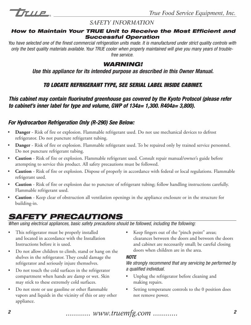
Leg Levelers:Ifthecabinetisnotleveluseanopen-endwrenchandturnadjustabletipsonlegsuntilcoolerislevel.(Seeimage1).
Castor Installation:(KitContents)2-Castormountingbracket2-Castor,2-1/2”diameterwheelwith3/8”-16x1- 1/2”threadedstemwithoutbrake2-Castor,2-1/2”diameterwheelwith3/8”-16x1- 1/2”threadedstemwithbrake
4-Washer,flat,3/8”I.D.x1”O.D.4-Washer,splitlock,3/8”I.D.4-Nut,hex,3/8”-16(See image 2).
CAUTIONTo avoid damage to lower rail assembly, slowly raise unit to upright position after installing castors.
2
A. Beforeyournewunitisconnectedtoapowersupply,checktheincomingvoltagewithavoltmeter.Ifanythinglessthan100%oftheratedvoltageforoperationisnoted,correctimmediately.
B. Allunitsareequippedwithaservicecord,andmustbepoweredatproperoperatingvoltageatalltimes.Refertocabinetdataplateforthisvoltage.
TRUErequiresthatasolecircuitbededicatedfortheunit.Failuretodosovoidswarranty.WARNINGCompressor warranties are void if compressor burns out due to low voltage.
WARNINGPower supply cord ground should not be removed!WARNINGDo not use electrical appliances inside the food storagecompartments of the appliances unless they are of thetype recommended by the manufacturer.
NOTETo reference wiring diagram - Remove lower rear grill. Wiring diagram is positioned on the inside cabinet wall.
ELECTRICAL INSTRUCTIONS
LEVELINGSecuring Castors
A. Setunitinitsfinallocation.Besurethereisadequateventilationinyourroom.Underextremeheatconditions,youmaywanttoinstallanexhaustfan.
WARNINGWarranty is void if ventilation is insufficient.B. ProperlevelingofyourTRUEcooleriscriticalto
operatingsuccess(fornon-mobilemodels).Effectivecondensateremovalanddooroperationwillbeeffectedbyleveling.
C. Thecoolershouldbeleveledinsidethecabinetfronttobackandsidetosidewithalevel.
D. Ensurethatthedrainhoseorhosesarepositionedinthepan.
E. Freeplugandcordfrominsidethelowerrearofthecooler(donotplugin).
F. Theunitshouldbeplacedcloseenoughtotheelectricalsupplysothatextensioncordsareneverused.
WARNING Cabinet warranties are void if OEM power cord is tampered with. TRUE will not warranty any units that are connected to an extension cord.
INSTALLATION OF LEGS AND CASTORS
1
............ www.truemfg.com ............
True Food Service Equipment, Inc.
8 8
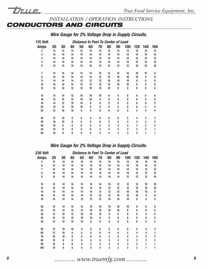
INSTALLATION / OPERATION INSTRUCTIONSCONDUCTORS AND CIRCUITS
Wire Gauge for 2% Voltage Drop in Supply Circuits. 115 Volt Distance In Feet To Center of Load Amps 20 30 40 50 60 70 80 90 100 120 140 160 2 14 14 14 14 14 14 14 14 14 14 14 14 3 14 14 14 14 14 14 14 14 14 14 14 12 4 14 14 14 14 14 14 14 14 14 12 12 12 5 14 14 14 14 14 14 14 12 12 12 10 10 6 14 14 14 14 14 14 12 12 12 10 10 10
7 14 14 14 14 14 12 12 12 10 10 10 8 8 14 14 14 14 12 12 12 10 10 10 8 8 9 14 14 14 12 12 12 10 10 10 8 8 8 10 14 14 14 12 12 10 10 10 10 8 8 8 12 14 14 12 12 10 10 10 8 8 8 8 6
14 14 14 12 10 10 10 8 8 8 6 6 6 16 14 12 12 10 10 8 8 8 8 6 6 6 18 14 12 10 10 8 8 8 8 8 8 8 5 20 14 12 10 10 8 8 8 6 6 6 5 5 25 12 10 10 8 8 6 6 6 6 5 4 4
30 12 10 8 8 6 6 6 6 5 4 4 3 35 10 10 8 6 6 6 5 5 4 4 3 2 40 10 8 8 6 6 5 5 4 4 3 2 2 45 10 8 6 6 6 5 4 4 3 3 2 1 50 10 8 6 6 5 4 4 3 3 2 1 1
Wire Gauge for 2% Voltage Drop in Supply Circuits. 230 Volt Distance In Feet To Center of Load Amps 20 30 40 50 60 70 80 90 100 120 140 160 5 14 14 14 14 14 14 14 14 14 14 14 14 6 14 14 14 14 14 14 14 14 14 14 14 12 7 14 14 14 14 14 14 14 14 14 14 12 12 8 14 14 14 14 14 14 14 14 14 12 12 12 9 14 14 14 14 14 14 14 14 12 12 12 10
10 14 14 14 14 14 14 14 12 12 12 10 10 12 14 14 14 14 14 14 12 12 12 10 10 10 14 14 14 14 14 14 12 12 12 10 10 10 8 16 14 14 14 14 12 12 12 10 10 10 8 8 18 14 14 14 12 12 12 10 10 10 8 8 8
20 14 14 14 12 10 10 10 10 10 8 8 8 25 14 14 12 12 10 10 10 10 8 8 6 6 30 14 12 12 10 10 10 8 8 8 6 6 6 35 14 12 10 10 10 8 8 8 8 6 6 5 40 14 12 10 10 8 8 8 6 6 6 5 5
50 12 10 10 8 6 6 6 6 6 5 4 4 60 12 10 8 6 6 6 6 6 5 4 4 3 70 10 10 8 6 6 6 5 5 4 4 2 2 80 10 8 8 6 6 5 5 4 4 3 2 2 90 10 8 6 6 5 5 4 4 3 3 1 1 100 10 8 6 6 5 4 4 3 3 2 1 1
............ www.truemfg.com ............
True Food Service Equipment, Inc.
9 9
INSTALLATION / OPERATION INSTRUCTIONS
A. Thecompressorisreadytooperate.Plugintheunit.
PLEASE REVIEW THE FOLLOWING CAUTIONS WHEN THE OPTIONAL HEATED PAN IS USED.
CAUTION This unit has two power supply cords. Unplug both
cords before moving or servicing this appliance.
CAUTION This unit has two power supply cords. Connect
each plug to a receptacle that is connected to an individual branch circuit.
CAUTION This unit has more than one disconnect switch (plug).
B. TemperaturecontrolsetatNo.4positiongivesrefrigeratorsanapproximatetemperatureof33°Fto38˚F(.5˚Cto3.3˚C).Allowunittofunctionseveralhours,completelycoolingcabinetbeforechangingthecontrolsetting.
C. Excessivetamperingwiththecontrolcouldleadtoservicedifficulties.Shoulditeverbecomenecessarytoreplacetemperaturecontrol,besureitisorderedfromyourTRUEdealerorrecommendedserviceagent.
D. GoodairflowinyourTRUEunitiscritical.Becarefultoloadproductsothatitneitherpressesagainstthebackwall,norcomeswithinfourinchesoftheevaporatorhousing.Refrigeratedairoffthecoilmustcirculatedownthefrontoftheshelves.
NOTEIf the unit is disconnected or shut off, wait five minutes before starting again.
RECOMMENDATIONBefore loading product we recommend you run your TRUE unit empty for two to three days. This allows you to be sure electrical wiring and installation are correct and no shipping damage has occurred. Remember, our factory warranty does not cover product loss!
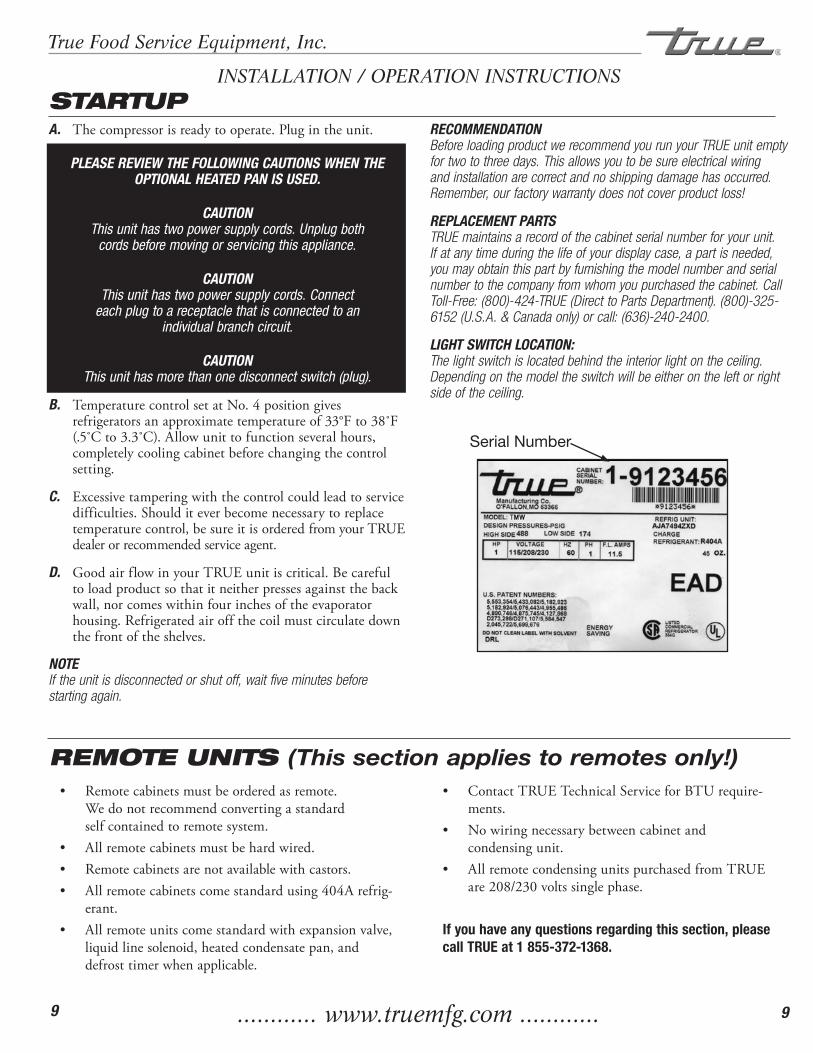
REPLACEMENT PARTSTRUE maintains a record of the cabinet serial number for your unit. If at any time during the life of your display case, a part is needed, you may obtain this part by furnishing the model number and serial number to the company from whom you purchased the cabinet. Call Toll-Free: (800)-424-TRUE (Direct to Parts Department). (800)-325-6152 (U.S.A. & Canada only) or call: (636)-240-2400.
LIGHT SWITCH LOCATION:The light switch is located behind the interior light on the ceiling. Depending on the model the switch will be either on the left or right side of the ceiling.
STARTUP
Serial Number
• Remotecabinetsmustbeorderedasremote.Wedonotrecommendconvertingastandardselfcontainedtoremotesystem.
• Allremotecabinetsmustbehardwired.• Remotecabinetsarenotavailablewithcastors.• Allremotecabinetscomestandardusing404Arefrig-
erant.• Allremoteunitscomestandardwithexpansionvalve,
liquidlinesolenoid,heatedcondensatepan,anddefrosttimerwhenapplicable.
• ContactTRUETechnicalServiceforBTUrequire-ments.
• Nowiringnecessarybetweencabinetandcondensingunit.
• AllremotecondensingunitspurchasedfromTRUEare208/230voltssinglephase.
If you have any questions regarding this section, please call TRUE at 1 855-372-1368.
REMOTE UNITS (This section applies to remotes only!)
............ www.truemfg.com ............
True Food Service Equipment, Inc.
10 10
TAC MECHANICAL TEMPERATURE CONTROL ALTITUDE ADJUSTMENTRequired Tools:• PhillipsHeadScrewdriver• 1/4"NutDriverBit• Slotted(Standard)ScrewDriver• 5/32"AllenKey
Temperature Control Adjustments:STEP 1Unplugthecooler.
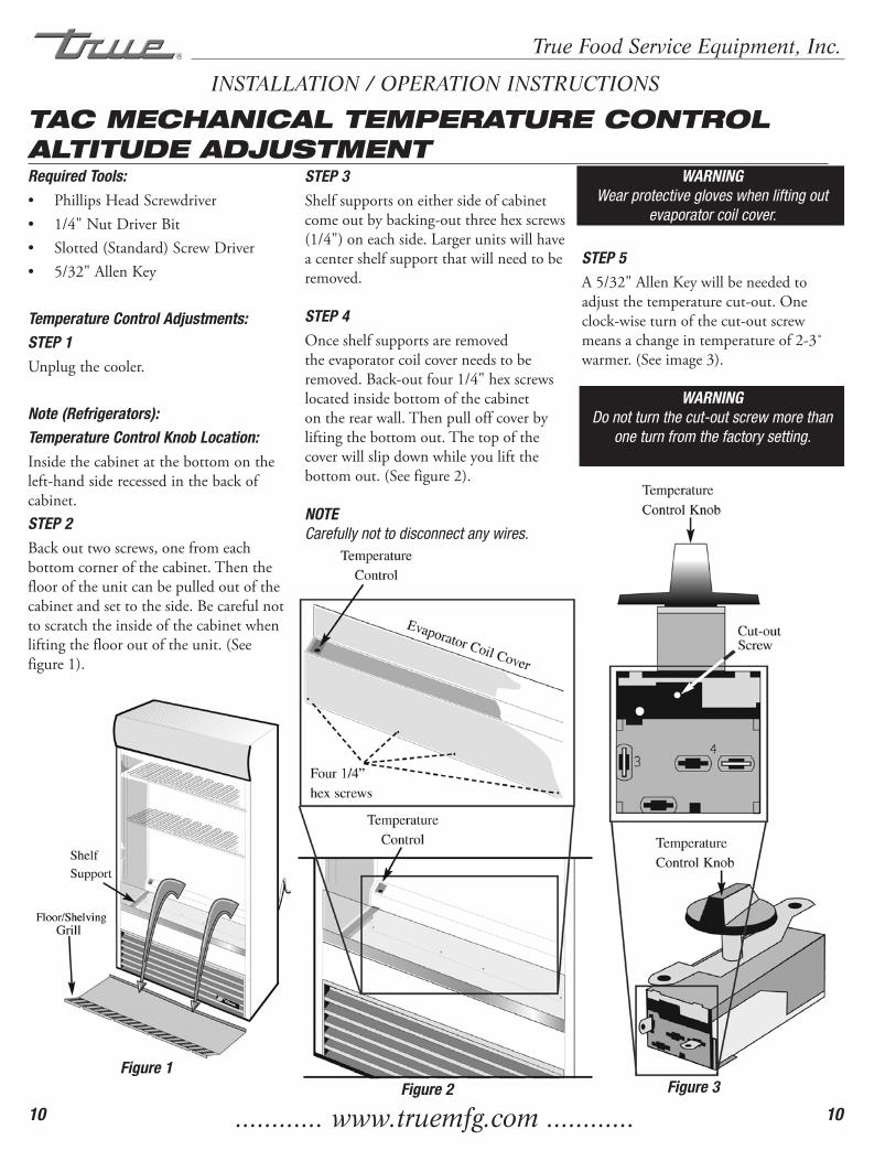
Note (Refrigerators):Temperature Control Knob Location:Insidethecabinetatthebottomontheleft-handsiderecessedinthebackofcabinet.STEP 2Backouttwoscrews,onefromeachbottomcornerofthecabinet.Thentheflooroftheunitcanbepulledoutofthecabinetandsettotheside.Becarefulnottoscratchtheinsideofthecabinetwhenliftingtheflooroutoftheunit.(Seefigure1).
STEP 3Shelfsupportsoneithersideofcabinetcomeoutbybacking-outthreehexscrews(1/4")oneachside.Largerunitswillhaveacentershelfsupportthatwillneedtoberemoved.
STEP 4Onceshelfsupportsareremovedtheevaporatorcoilcoverneedstoberemoved.Back-outfour1/4"hexscrewslocatedinsidebottomofthecabinetontherearwall.Thenpulloffcoverbyliftingthebottomout.Thetopofthecoverwillslipdownwhileyouliftthebottomout.(Seefigure2).
NOTECarefully not to disconnect any wires.
WARNINGWear protective gloves when lifting out
evaporator coil cover.
STEP 5A5/32"AllenKeywillbeneededtoadjustthetemperaturecut-out.Oneclock-wiseturnofthecut-outscrewmeansachangeintemperatureof2-3˚warmer.(Seeimage3).
WARNINGDo not turn the cut-out screw more than
one turn from the factory setting.
INSTALLATION / OPERATION INSTRUCTIONS
Figure 1Figure 2 Figure 3
............ www.truemfg.com ............
True Food Service Equipment, Inc.
11 11
TAC MECHANICAL TEMPERATURE CONTROL ALTITUDE ADJUSTMENT ... CONTINUED ...
Temperature Control Adjustments
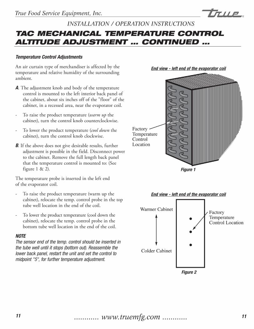
Anaircurtaintypeofmerchandiserisaffectedbythetemperatureandrelativehumidityofthesurroundingambient.
A.Theadjustmentknobandbodyofthetemperaturecontrolismountedtotheleftinteriorbackpanelofthecabinet,aboutsixinchesoffofthe"floor"ofthecabinet,inarecessedarea,neartheevaporatorcoil.
- Toraisetheproducttemperature(warm upthecabinet),turnthecontrolknobcounterclockwise.
- Tolowertheproducttemperature(cool downthecabinet),turnthecontrolknobclockwise.
B.Iftheabovedoesnotgivedesirableresults,furtheradjustmentispossibleinthefield.Disconnectpowertothecabinet.Removethefulllengthbackpanelthatthetemperaturecontrolismountedto:(Seefigure1&2).
Thetemperatureprobeisinsertedintheleftendoftheevaporatorcoil.
- Toraisetheproducttemperature(warmupthecabinet),relocatethetemp.controlprobeinthetoptubewelllocationintheendofthecoil.
- Tolowertheproducttemperature(cooldownthecabinet),relocatethetemp.controlprobeinthebottomtubewelllocationintheendofthecoil.
NOTE The sensor end of the temp. control should be inserted in the tube well until it stops (bottom out). Reassemble the lower back panel, restart the unit and set the control to midpoint "5", for further temperature adjustment.
INSTALLATION / OPERATION INSTRUCTIONS
End view - left end of the evaporator coil
End view - left end of the evaporator coil
Figure 1
Figure 2
............ www.truemfg.com ............
True Food Service Equipment, Inc.
12 12
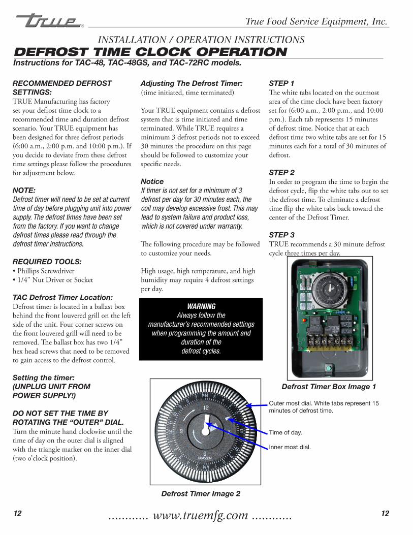
INSTALLATION / OPERATION INSTRUCTIONSDEFROST TIME CLOCK OPERATIONInstructions for TAC-48, TAC-48GS, and TAC-72RC models.
RECOMMENDED DEFROST SETTINGS:TRUEManufacturinghasfactorysetyourdefrosttimeclocktoarecommendedtimeanddurationdefrostscenario.YourTRUEequipmenthasbeendesignedforthreedefrostperiods(6:00a.m.,2:00p.m.and10:00p.m.).Ifyoudecidetodeviatefromthesedefrosttimesettingspleasefollowtheproceduresforadjustmentbelow.
NOTE:Defrost timer will need to be set at current time of day before plugging unit into power supply. The defrost times have been set from the factory. If you want to change defrost times please read through the defrost timer instructions.
REQUIRED TOOLS:•PhillipsScrewdriver•1/4”NutDriverorSocket
TAC Defrost Timer Location:Defrosttimerislocatedinaballastboxbehindthefrontlouveredgrillontheleftsideoftheunit.Fourcornerscrewsonthefrontlouveredgrillwillneedtoberemoved.Theballastboxhastwo1/4”hexheadscrewsthatneedtoberemovedtogainaccesstothedefrostcontrol.
Setting the timer:(UNPLUG UNIT FROM POWER SUPPLY!)
DO NOT SET THE TIME BY ROTATING THE “OUTER” DIAL.Turntheminutehandclockwiseuntilthetimeofdayontheouterdialisalignedwiththetrianglemarkerontheinnerdial(twoo’clockposition).
Adjusting The Defrost Timer:(timeinitiated,timeterminated)
YourTRUEequipmentcontainsadefrostsystemthatistimeinitiatedandtimeterminated.WhileTRUErequiresaminimum3defrostperiodsnottoexceed30minutestheprocedureonthispageshouldbefollowedtocustomizeyourspecificneeds.
NoticeIf timer is not set for a minimum of 3 defrost per day for 30 minutes each, the coil may develop excessive frost. This may lead to system failure and product loss, which is not covered under warranty.
Thefollowingproceduremaybefollowedtocustomizeyourneeds.
Highusage,hightemperature,andhighhumiditymayrequire4defrostsettingsperday.
WARNINGAlways follow the
manufacturer’s recommended settings when programming the amount and
duration of the defrost cycles.
Defrost Timer Image 2
STEP 1Thewhitetabslocatedontheoutmostareaofthetimeclockhavebeenfactorysetfor(6:00a.m.,2:00p.m.,and10:00p.m.).Eachtabrepresents15minutesofdefrosttime.Noticethatateachdefrosttimetwowhitetabsaresetfor15minuteseachforatotalof30minutesofdefrost.
STEP 2Inordertoprogramthetimetobeginthedefrostcycle,flipthewhitetabsouttosetthedefrosttime.ToeliminateadefrosttimeflipthewhitetabsbacktowardthecenteroftheDefrostTimer.
STEP 3TRUErecommendsa30minutedefrostcyclethreetimesperday.
Defrost Timer Box Image 1
Outer most dial. White tabs represent 15 minutes of defrost time.
Time of day.
Inner most dial.

............ www.truemfg.com ............
True Food Service Equipment, Inc.
13 13
TAC DIGITAL TEMPERATURE CONTROL OPERATION
Digital Temperature Control Commands
Use of LEDEach LED function is described in the following table.
KEY COMBINATIONS
Tolock&unlockthekeyboard.
Tolock&unlockthekeyboard.
Tolock&unlockthekeyboard.
HOW TO SEE THE MINIMUM TEMPERATURE:
1.Pressandreleasethekey. 2.The"Lo"messagewillbedisplayed followedbytheminimumtemperature recorded. 3.Bypressingthekeyorwaitingfor5 secondsthenormaldisplaywillberestored.
HOW TO SEE THE MAXIMUM TEMPERATURE:
1.Pressandreleasethekey. 2.The"Hi"messagewillbedisplayed followedbythemaximumtemperature recorded. 3.Bypressingthekeyorwaitingfor 5sthenormaldisplaywillberestored.
HOW TO RESET THE MAXIMUM AND MINIMUM TEMPERATURE RECORDED:
Toresetthestoredtemperature,whenmaximumorminimumtemperatureisdisplayed:
1.PressSETkeyuntil"rST"labelstartsblinking.
HOW TO SEE AND MODIFY THE SET POINT:
1.PushandimmediatelyreleasetheSET key:thedisplaywillshowtheSetpoint value;
2.TheSETLEDstartblinking;
3.TochangetheSetvaluepushtheor arrowswithin10seconds.
TO START A MANUAL DEFROST:
1.PushtheDefrostkeyformorethan2 secondsandamanualdefrostwillstart.
HOW TO LOCK THE KEYBOARD:
1.Keeptheandkeyspressed togetherformorethan3seconds.
2.The"POF"messagewillbedisplayed andthekeyboardislocked.Atthis pointitisonlypossibletoviewtheset pointandtheMAXIMUMORMINIMUM temperaturesstored.
TO UNLOCK THE KEYBOARD:1. Keeptheandkeyspressedtogetherformorethan3seconds.2. The"PON"messagewillbedisplayedandthe keyboardisunlocked.
INSTALLATION / OPERATION INSTRUCTIONS

............ www.truemfg.com ............
True Food Service Equipment, Inc.
14 14
DIGITAL TEMPERATURE CONTROLLER PROGRAMMING INSTRUCTIONS CONTINUED ....
............ www.truemfg.com ............
True Food Service Equipment, Inc.
15 15
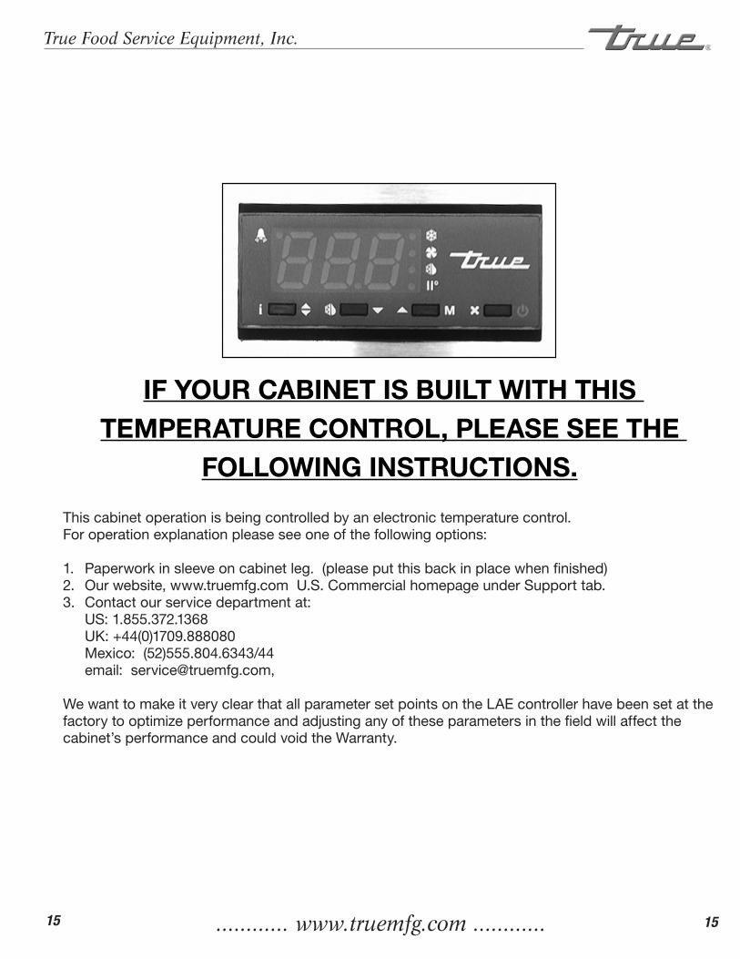
This cabinet operation is being controlled by an electronic temperature control.For operation explanation please see one of the following options:
1. Paperwork in sleeve on cabinet leg. (please put this back in place when finished)2. Our website, www.truemfg.com U.S. Commercial homepage under Support tab.3. Contact our service department at: US: 1.855.372.1368 UK: +44(0)1709.888080 Mexico: (52)555.804.6343/44 email: [email protected],
We want to make it very clear that all parameter set points on the LAE controller have been set at the factory to optimize performance and adjusting any of these parameters in the field will affect the cabinet’s performance and could void the Warranty.
IF YOUR CABINET IS BUILT WITH THIS TEMPERATURE CONTROL, PLEASE SEE THE
FOLLOWING INSTRUCTIONS.

............ www.truemfg.com ............
True Food Service Equipment, Inc.
16 16
LAE CONTROLSEQUENCE OF OPERATION
1. Cabinet is plugged in.
a. Display will illuminate. b. Interior light will illuminate on glass door models only. (If lights do not come on please see
instructions on following page(s).) Solid door cabinet lights are controlled by door switch.
2. After the LAE control preprogrammed time delay of 3 minutes, the compressor and evaporator fan(s) will start if the control is calling for cooling.
a. Control may be already pre-programmed from the factory so at the start of every compressor cycle or
during a defrost cycle, the condenser fan(s) will reverse for 30 seconds to blow dirt off the condensing coil.
3. The LAE control will cycle the compressor but may also cycle evaporator fan(s) on and off determined by the Set-Point and Differential temperatures. (If the Set-Point needs to be changed due to conditions please see instructions on the following page(s).)
a. The Set-Point is the preprogrammed temperature which shuts off the compressor. b. The Differential is the preprogrammed temperature that is added to the Set-Point temperature that will
start the compressor.
Example: If the Set-Point is -9°F/-23°C and the Differential is 10°F/5°C (Set-Point) -9°F + 10 (Differential) = 1°F Or (Set-Point) -23°C + 5 (Differential) = -18°C The compressor and evaporator fan(s) will cycle off -9°F/-23°C and back on at 1°F/-18°C
4. The LAE control may be preprogrammed to initiate defrost by interval or at specific times of day. (If additional Defrost Intervals or Cycles are needed or a Manual Defrost is required due to conditions please see instruc-tions on the following page(s).)
a. At this time the “dEF” will appear on the display and compressor will turn off until a preprogrammed
temperature or duration is reached. During this time for freezers only, evaporator fan(s) will also turn off and the coil heater and drain tube heaters will also be energized.
b. After the preprogrammed temperature or duration for defrost has been reached there may be a short
delay for both the compressor and evaporator fans to restart. At this time “dEF” may still appear on the display for a short time.
True Manufacturing recommends that ONLY the Set-Point and/or Defrost Interval may be adjusted due to certain conditions.
This sequence is NOT model specific.
If you have any questions, please contact the Technical Service Department. Phone: 855-372-1368 • Email: [email protected]
............ www.truemfg.com ............
True Food Service Equipment, Inc.
17 17
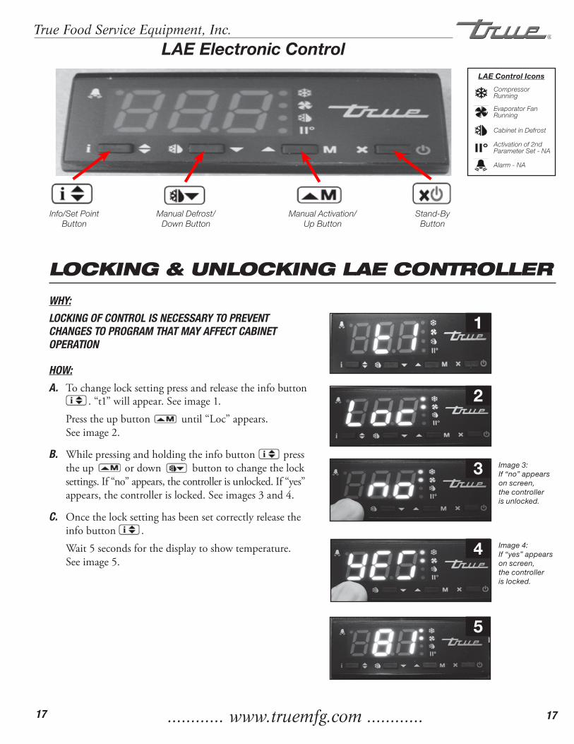
LOCKING & UNLOCKING LAE CONTROLLER
WHY:
LOCKING OF CONTROL IS NECESSARY TO PREVENT CHANGES TO PROGRAM THAT MAY AFFECT CABINET OPERATION
HOW:
A. Tochangelocksettingpressandreleasetheinfobutton.“t1”willappear.Seeimage1.
Presstheupbuttonuntil“Loc”appears.Seeimage2.
B. Whilepressingandholdingtheinfobuttonpresstheupordownbuttontochangethelocksettings.If“no”appears,thecontrollerisunlocked.If“yes”appears,thecontrollerislocked.Seeimages3and4.
C. Oncethelocksettinghasbeensetcorrectlyreleasetheinfobutton.
Wait5secondsforthedisplaytoshowtemperature.Seeimage5.
1
2
5
LAE Electronic Control
Info/Set Point Button
Manual Defrost/ Down Button
Manual Activation/ Up Button
Stand-ByButton
3 Image 3: If “no” appears on screen, the controller is unlocked.
4 Image 4: If “yes” appears on screen, the controller is locked.
Compressor Running
Activation of 2nd Parameter Set - NA
Alarm - NA
Cabinet in Defrost
Evaporator Fan Running
LAE Control Icons

............ www.truemfg.com ............
True Food Service Equipment, Inc.
18 18
HOW TO TURN LIGHTS ON/OFF
WHY:
LIGHT MAY BE CONTROLLED BY LAE CONTROLLER OR INTE-RIOR LIGHT SWITCH.
HOW:
A. Tocontrolinterior/signlightsbytheLAEController,pressandreleasethe“ManualActivation”button.
B. Tocontrolinterior/signlightsbytheinteriordoorswitch,depresstherockerswitchtothe“ON”position.LightSwitchislocatedoninsidetoprightortopleftoftheceiling.
ON Position
May need to unlock control.
LAE Electronic Control
Info/Set Point Button
Manual Defrost/ Down Button
Manual Activation/ Up Button
Stand-ByButton
Compressor Running
Activation of 2nd Parameter Set - NA
Alarm - NA
Cabinet in Defrost
Evaporator Fan Running
LAE Control Icons
............ www.truemfg.com ............
True Food Service Equipment, Inc.
19 19
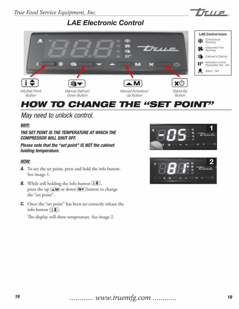
LAE Electronic Control
Info/Set Point Button
Manual Defrost/ Down Button
Manual Activation/ Up Button
Stand-ByButton
1
2
Compressor Running
Activation of 2nd Parameter Set - NA
Alarm - NA
Cabinet in Defrost
Evaporator Fan Running
LAE Control Icons
May need to unlock control.WHY:
THE SET POINT IS THE TEMPERATURE AT WHICH THE COMPRESSOR WILL SHUT OFF.
Please note that the “set point” IS NOT the cabinet holding temperature.
HOW:
A. Toseethesetpoint,pressandholdtheinfobutton.Seeimage1.
B. Whilestillholdingtheinfobutton,presstheupordownbuttontochangethe“setpoint”.
C. Oncethe“setpoint”hasbeensetcorrectlyreleasetheinfobutton.
Thedisplaywillshowtemperature.Seeimage2.
HOW TO CHANGE THE “SET POINT”
............ www.truemfg.com ............
True Food Service Equipment, Inc.
20 20
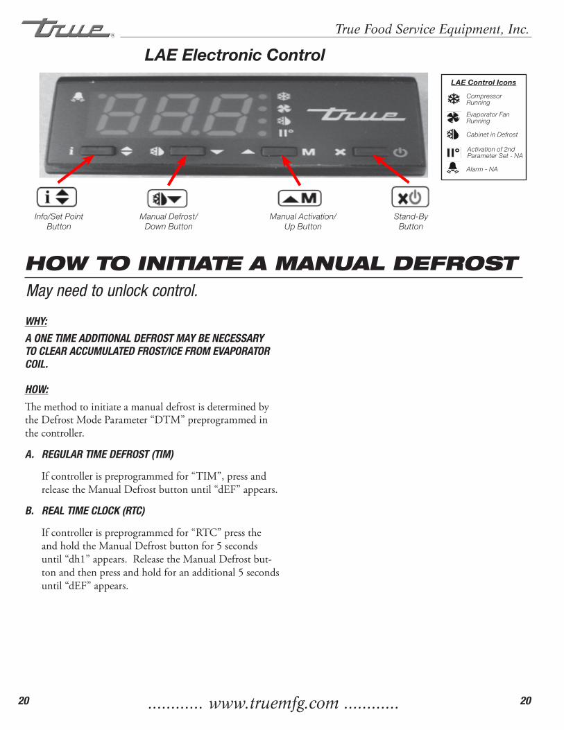
HOW TO INITIATE A MANUAL DEFROSTMay need to unlock control.
WHY:
A ONE TIME ADDITIONAL DEFROST MAY BE NECESSARY TO CLEAR ACCUMULATED FROST/ICE FROM EVAPORATOR COIL.
HOW:
ThemethodtoinitiateamanualdefrostisdeterminedbytheDefrostModeParameter“DTM”preprogrammedinthecontroller.
A. REGULAR TIME DEFROST (TIM)
Ifcontrollerispreprogrammedfor“TIM”,pressandreleasetheManualDefrostbuttonuntil“dEF”appears.
B. REAL TIME CLOCK (RTC)
Ifcontrollerispreprogrammedfor“RTC”presstheandholdtheManualDefrostbuttonfor5secondsuntil“dh1”appears.ReleasetheManualDefrostbut-tonandthenpressandholdforanadditional5secondsuntil“dEF”appears.
LAE Electronic Control
Info/Set Point Button
Manual Defrost/ Down Button
Manual Activation/ Up Button
Stand-ByButton
Compressor Running
Activation of 2nd Parameter Set - NA
Alarm - NA
Cabinet in Defrost
Evaporator Fan Running
LAE Control Icons

............ www.truemfg.com ............
True Food Service Equipment, Inc.
21 21
1
2
3
4
LAE Electronic Control
Info/Set Point Button
Manual Defrost/ Down Button
Manual Activation/ Up Button
Stand-ByButton
Compressor Running
Activation of 2nd Parameter Set - NA
Alarm - NA
Cabinet in Defrost
Evaporator Fan Running
LAE Control Icons
WHY:
THE DEFROST INTERVAL IS THE TIME DURATION BETWEEN DEFROST CYCLES.
The Defrost Interval time starts when the cabinet is supplied power or after a manual defrost.
HOW:
A. Toseethesetpoint,pressandholdtheinfobutton andthestand-bybuttonatthesametime.“ScL”willappear.Seeimage1.
B. Pushtheupbuttonuntil“dFt”appears. Seeimage2.
C. Pressandholdtheinfobuttontoseethe“defrostintervaltime”.Seeimage3.
D. Whilepressingandholdingtheinfobutton,presstheupordownbuttontochangethe“defrostintervaltimes”(higherthenumberthelessfrequentthecabinetwilldefrost).
E. Oncethe“defrostintervaltime”hasbeenchanged,releasetheinfobutton.
Wait30secondsforthedisplaytoshowtemperature.Seeimage4.
HOW TO CHANGE “DEFROST INTERVALS”May need to unlock control.This can only be changed if defrost mode parameter “DFM” is set for “TIM”.
............ www.truemfg.com ............
True Food Service Equipment, Inc.
22 22
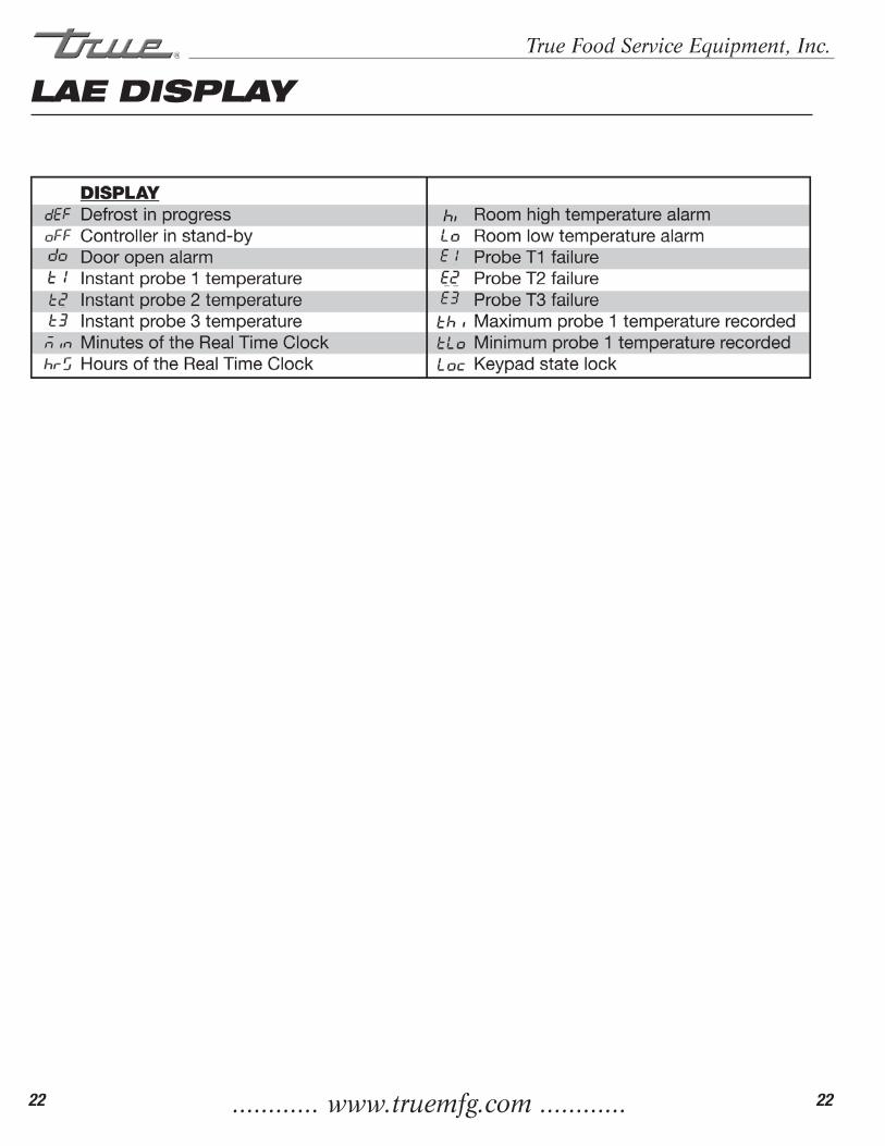
LAE DISPLAY
............ www.truemfg.com ............
True Food Service Equipment, Inc.
23 23
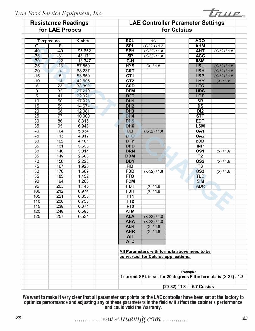
K-ohm SCL 1C ADOC F SPL (X-32 ) / 1.8 AHM
-40 -40 195.652 SPH (X-32) / 1.8 AHT (X-32) / 1.8-35 -31 148.171 SP (X-32) / 1.8 ACC-30 -22 113.347 C-H IISM-25 -13 87.559 HYS (X) / 1.8 IISL (X-32) / 1.8-20 -4 68.237 CRT IISH (X-32) / 1.8-15 5 53.650 CT1 IISP (X-32) / 1.8-10 14 42.506 CT2 IIHY (X) / 1.8-5 23 33.892 CSD IIFC0 32 27.219 DFM HDS5 41 22.021 DFT IIDF
10 50 17.926 DH1 SB15 59 14.674 DH2 DS20 68 12.081 DH3 DI225 77 10.000 DH4 STT30 86 8.315 DH5 EDT35 95 6.948 DH6 LSM40 104 5.834 DLI (X-32) / 1.8 OA145 113 4.917 DTO OA250 122 4.161 DTY 2CD55 131 3.535 DPD INP60 140 3.014 DRN OS1 (X) / 1.865 149 2.586 DDM T270 158 2.228 DDY OS2 (X) / 1.875 167 1.925 FID T380 176 1.669 FDD (X-32) / 1.8 OS3 (X) / 1.885 185 1.452 FTO TLD90 194 1.268 FCM SIM95 203 1.145 FDT (X) / 1.8 ADR
100 212 0.974 FDH (X) / 1.8105 221 0.858 FT1110 230 0.758 FT2115 239 0.671 FT3120 248 0.596 ATM125 257 0.531 ALA (X-32) / 1.8
AHA (X-32) / 1.8ALR (X) / 1.8AHR (X) / 1.8ATIATD
All Parameters with formula above need to beconverted for Celsius applications.
If current SPL is set for 20 degrees F the formula is (X-32) / 1.8
LAE Controller Parameter SettingsResistance Readings for LAE Probes for Celsius
(20-32) / 1.8 = -6.7 Celsius
Example:
Temperaure
SUBJECT TO CHANGE
We want to make it very clear that all parameter set points on the LAE controller have been set at the factory to optimize performance and adjusting any of these parameters in the field will affect the cabinet’s performance
and could void the Warranty.
............ www.truemfg.com ............
True Food Service Equipment, Inc.
24 24
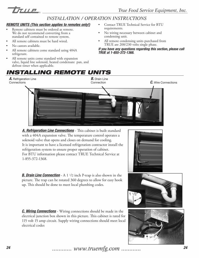
INSTALLATION / OPERATION INSTRUCTIONS
A. Refrigeration Line Connections-Thiscabinetisbuiltstandardwitha404Aexpansionvalve.Thetemperaturecontroloperatesasolenoidvalvethatopensandclosesondemandforcooling.Itisimportanttohavealicensedrefrigerationcontractorinstalltherefrigerationsystemtoensureproperoperationofcabinet.ForBTUinformationpleasecontactTRUETechnicalServiceat1-855-372-1368.
B. Drain Line Connection-A11/2inchP-trapisalsoshowninthepicture.Thetrapcanberotated360degreestoallowforeasyhookup.Thisshouldbedonetomeetlocalplumbingcodes.
C. Wiring Connections-Wiringconnectionsshouldbemadeintheelectricaljunctionboxshowninthispicture.Thiscabinetisratedfor115volt15ampcircuit.Supplywiringconnectionsshouldmeetlocalelectricalcodes
INSTALLING REMOTE UNITSA. Refrigeration Line Connections
B. Drain Line Connection C. Wire Connections
1 1/2"
REMOTE UNITS (This section applies to remotes only!)• Remotecabinetsmustbeorderedasremote.
Wedonotrecommendconvertingfroma standardselfcontainedtoremotesystem.
• Allremotecabinetsmustbehardwired.• Nocastorsavailable.• Allremotecabinetscomestandardusing404A
refrigerant.• Allremoteunitscomestandardwithexpansion
valve,liquidlinesolenoid,heatedcondensatepan,anddefrosttimerwhenapplicable.
• ContactTRUETechnicalServiceforBTU requirements.
• Nowiringnecessarybetweencabinetand condensingunit.
• Allremotecondensingunitspurchasedfrom TRUEare208/230voltssinglephase.
If you have any questions regarding this section, please call TRUE at 1-855-372-1368.
............ www.truemfg.com ............
True Food Service Equipment, Inc.
25 25
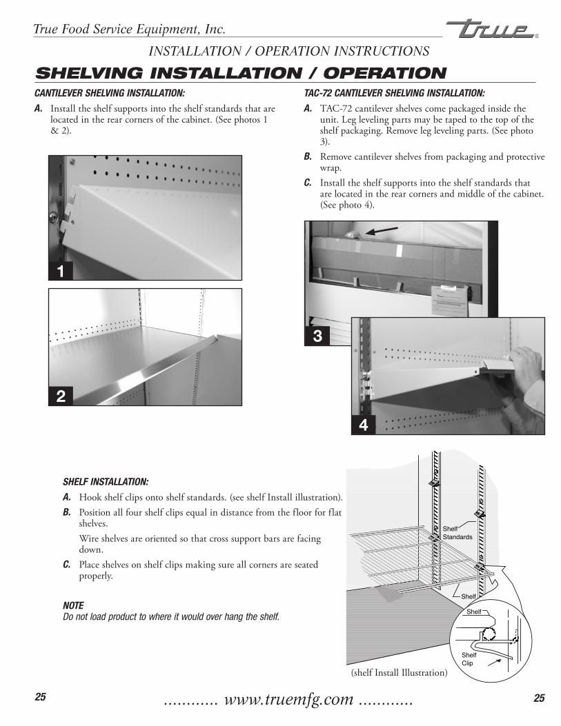
CANTILEVER SHELVING INSTALLATION:A. Installtheshelfsupportsintotheshelfstandardsthatare
locatedintherearcornersofthecabinet.(Seephotos1&2).
ShelfClip
Shelf
Shelf
ShelfStandards
SHELVING INSTALLATION / OPERATIONINSTALLATION / OPERATION INSTRUCTIONS
SHELF INSTALLATION:A. Hookshelfclipsontoshelfstandards.(seeshelfInstallillustration).B. Positionallfourshelfclipsequalindistancefromthefloorforflat
shelves. Wireshelvesareorientedsothatcrosssupportbarsarefacing
down.C. Placeshelvesonshelfclipsmakingsureallcornersareseated
properly.
NOTEDo not load product to where it would over hang the shelf.
(shelfInstallIllustration)
TAC-72 CANTILEVER SHELVING INSTALLATION:A. TAC-72cantilevershelvescomepackagedinsidethe
unit.Leglevelingpartsmaybetapedtothetopoftheshelfpackaging.Removeleglevelingparts.(Seephoto3).
B. Removecantilevershelvesfrompackagingandprotectivewrap.
C. Installtheshelfsupportsintotheshelfstandardsthatarelocatedintherearcornersandmiddleofthecabinet.(Seephoto4).
1
3
4
2
............ www.truemfg.com ............
True Food Service Equipment, Inc.
26 26
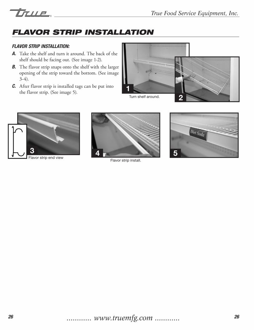
Flavor strip end viewFlavor strip install.
FLAVOR STRIP INSTALLATION
FLAVOR STRIP INSTALLATION:A. Taketheshelfandturnitaround.Thebackofthe
shelfshouldbefacingout.(Seeimage1-2).B. Theflavorstripsnapsontotheshelfwiththelarger
openingofthestriptowardthebottom.(Seeimage3-4).
C. Afterflavorstripisinstalledtagscanbeputintotheflavorstrip.(Seeimage5).
Turn shelf around.
12
3 4 5

............ www.truemfg.com ............
True Food Service Equipment, Inc.
27 27
MAINTENANCE, CARE & CLEANING
CLEANING THE CONDENSER COILWhen using electrical appliances, basic safety precautions should be followed, including the following
TOOLS REQUIRED:•Phillipsscrewdriver•Stiffbristlebrush•Adjustablewrench•Vacuum
Step 1Disconnect power to unit.
Step 2Take off front lower grill assembly by removing two (2) screws in lower corners.
Loosen screws holding the top pivot pins. Swing grill up and remove frame hooks from pivot pins at top of louver.
TAC-14GS Grill Removal:Remove two screws from either side of the front grill (See image 1). Lift grill away front cabinet (See image 2).
Step 3Clean off accumulated dirt from condensing coil with a stiff bristle brush.
Step 4After brushing condenser coil vacuum dirt from coil, and interior floor.
Step 5Replace grill assembly.
Step 6Connect unit to power and check to see if condensing unit is running.
All TRUE TAC Models are manufactured with Reversing Condenser Fan Motors. This kind of fan motor allows less dust and dirt to accumulate onto the condenser coil. This reduces the required cleaning time of the condenser coil
and allows for less expensive operating costs.
Step 1
Step 2
Image 1. Image 2.
............ www.truemfg.com ............
True Food Service Equipment, Inc.
28 28
MAINTENANCE, CARE & CLEANING
Condensers accumulate dirt and require cleaning every 30 days. Dirty condensers result in com-pressor failure, product loss, and lost sales... which are not covered by warranty.
If you keep the Condenser clean you will minimize your service expense and lower your electrical costs. The Condenser requires scheduled cleaning every thirty days or as needed.
Air is pulled through the Condenser continuously, along with dust, lint, grease, etc.
A dirty Condenser can result in NON-WARRANTEED part & Compressor Failures, Product Loss, and Lost Sales.
Proper cleaning involves removing dust from the Condenser. By using a soft brush, or vacuuming the Condenser with a shop vac, or using CO2, nitrogen, or pressurized air.
If you cannot remove the dirt adequately, please call your refrigeration service company.
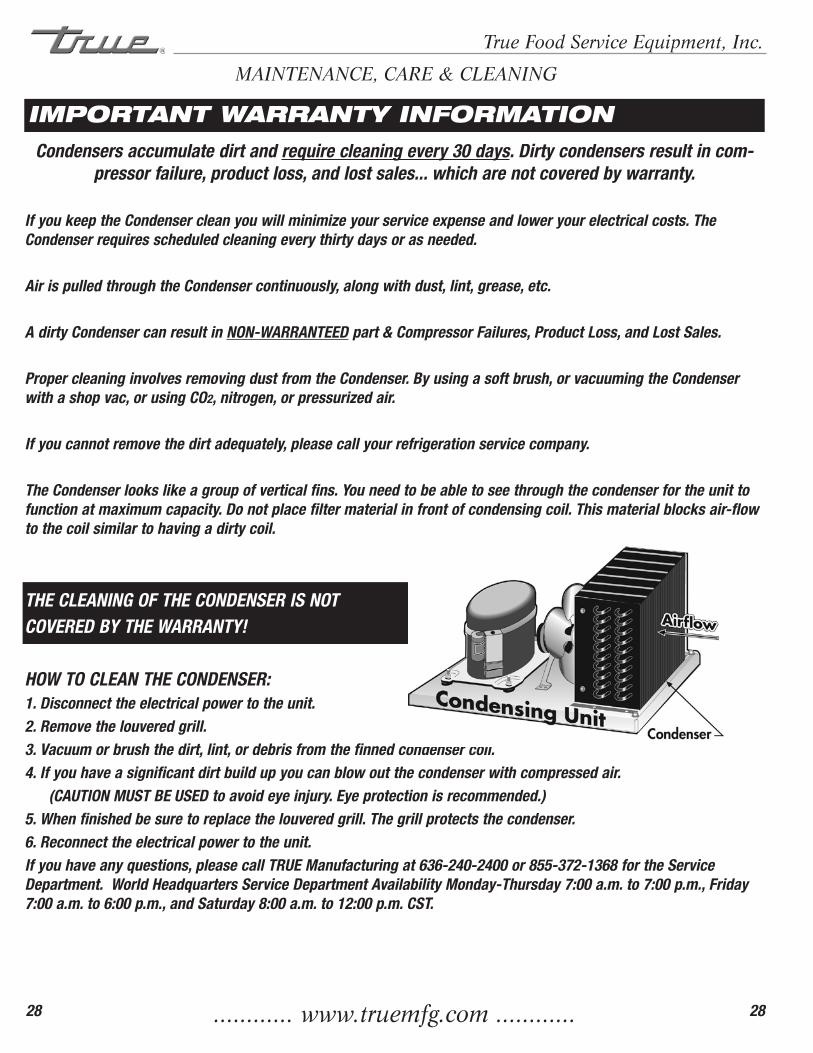
The Condenser looks like a group of vertical fins. You need to be able to see through the condenser for the unit to function at maximum capacity. Do not place filter material in front of condensing coil. This material blocks air-flow to the coil similar to having a dirty coil.
THE CLEANING OF THE CONDENSER IS NOT COVERED BY THE WARRANTY!
HOW TO CLEAN THE CONDENSER:1. Disconnect the electrical power to the unit.2. Remove the louvered grill.3. Vacuum or brush the dirt, lint, or debris from the finned condenser coil.4. If you have a significant dirt build up you can blow out the condenser with compressed air. (CAUTION MUST BE USED to avoid eye injury. Eye protection is recommended.)5. When finished be sure to replace the louvered grill. The grill protects the condenser.6. Reconnect the electrical power to the unit.If you have any questions, please call TRUE Manufacturing at 636-240-2400 or 855-372-1368 for the Service Department. World Headquarters Service Department Availability Monday-Thursday 7:00 a.m. to 7:00 p.m., Friday 7:00 a.m. to 6:00 p.m., and Saturday 8:00 a.m. to 12:00 p.m. CST.
IMPORTANT WARRANTY INFORMATION
............ www.truemfg.com ............
True Food Service Equipment, Inc.
29 29
CAUTION: Do not use any steel wool, abrasive or chlorine based products to clean stainless steel surfaces.• StainlessSteelOpponents Therearethreebasicthingswhichcanbreakdownyourstainlesssteel’spassivitylayerandallow
corrosiontorearitsuglyhead.1) Scratchesfromwirebrushes,scrapers,andsteelpadsarejustafewexamplesofitemsthatcanbeabrasivetostainless
steel’ssurface.2) Depositsleftonyourstainlesssteelcanleavespots.Youmayhavehardorsoftwaterdependingonwhatpartofthe
countryyoulivein.Hardwatercanleavespots.Hardwaterthatisheatedcanleavedepositsiflefttosittoolong.Thesedepositscancausethepassivelayertobreakdownandrustyourstainlesssteel.Alldepositsleftfromfoodpreporserviceshouldberemovedassoonaspossible.
3) Chloridesarepresentintablesalt,food,andwater.Householdandindustrialcleanersaretheworsttypeofchloridestouse.
• 8stepsthatcanhelppreventrustonstainlesssteel:1. Usingthecorrectcleaningtools Usenon-abrasivetoolswhencleaningyourstainlesssteelproducts.Thestainlesssteel’spassivelayerwillnotbeharmedby
softclothsandplasticscouringpads.Step2tellsyouhowtofindthepolishingmarks.2. Cleaningalongthepolishlines Polishinglinesor“grain”arevisibleonsomestainlesssteels.Alwaysscrubparalleltovisiblelinesonsomestainlesssteels.
Useaplasticscouringpadorsoftclothwhenyoucannotseethegrain.3. Usealkaline,alkalinechlorinatedornon-chloridecontainingcleaners Whilemanytraditionalcleanersareloadedwithchlorides,theindustryisprovidinganeverincreasingchoiceofnon-
chloridecleaners.Ifyouarenotsureofyourcleaner’schloridecontentcontactyourcleanersupplier.Iftheytellyouthatyourpresentcleanercontainschlorides,askiftheyhaveanalternative.Avoidcleanerscontainingquaternarysaltsastheycanattackstainlesssteel,causingpittingandrusting.
4. WaterTreatment Toreducedeposits,softenthehardwaterwhenpossible.Installationofcertainfilterscanremovecorrosiveanddistasteful
elements.Saltsinaproperlymaintainedwatersoftenercanbetoyouradvantage.Contactatreatmentspecialistifyouarenotsureoftheproperwatertreatment.
5. Maintainingthecleanlinessofyourfoodequipment Usecleanersatrecommendedstrength(alkaline,alkalinechlorinatedornon-chloride).Avoidbuild-upofhardstainsby
cleaningfrequently.Whenboilingwaterwithyourstainlesssteelequipment,thesinglemostlikelycauseofdamageischloridesinthewater.Heatinganycleanerscontainingchlorideswillhavethesamedamagingeffects.
6. Rinse Whenusingchlorinatedcleanersyoumustrinseandwipedryimmediately.Itisbettertowipestandingcleaningagents
andwaterassoonaspossible.Allowthestainlesssteelequipmenttoairdry.Oxygenhelpsmaintainthepassivityfilmonstainlesssteel.
7. Hydrochloricacid(muriaticacid)shouldneverbeusedonstainlesssteel8. Regularlyrestore/passivatestainlesssteel
STAINLESS STEEL EQUIPMENT CARE AND CLEANINGMAINTENANCE, CARE & CLEANING
............ www.truemfg.com ............
True Food Service Equipment, Inc.
30 30
Recommended cleaners for certain situations / environments of stainless steelA) Soap,ammoniaanddetergentmedallionappliedwithaclothorspongecanbeusedforroutinecleaning.B) Arcal20,Lac-O-NuEcoshineappliedprovidesbarrierfilmforfingerprintsandsmears.C) Cameo,Talc,ZudFirstImpressionisappliedbyrubbinginthedirectionofthepolishedlinesfor
stubbornstainsanddiscoloring.D)Easy-offandDe-GreaseItovenaidareexcellentforremovalsonallfinishesforgrease-fattyacids,
bloodandburnt-onfoods.E) Anygoodcommercialdetergentcanbeappliedwithaspongeorclothtoremovegreaseandoil.F) Benefit,SuperSheen,SheilaShinearegoodforrestoration/passivation.
NOTE:
The use of stainless steel cleaners or other such solvents is not
recommended on plastic parts. Warm soap and water will suffice.
STAINLESS STEEL EQUIPMENT CARE AND CLEANING
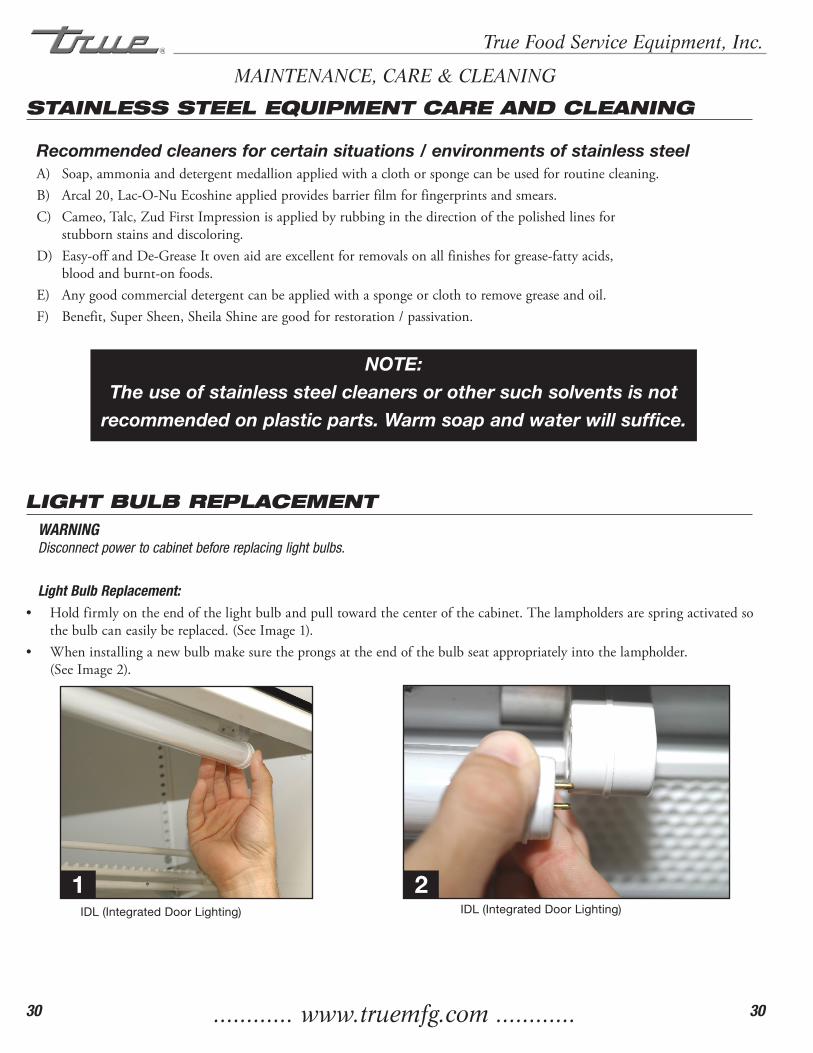
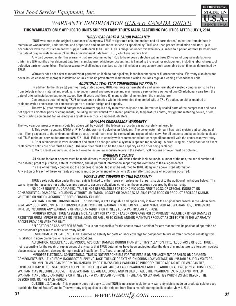
LIGHT BULB REPLACEMENTWARNING Disconnect power to cabinet before replacing light bulbs.
Light Bulb Replacement:• Holdfirmlyontheendofthelightbulbandpulltowardthecenterofthecabinet.Thelampholdersarespringactivatedso
thebulbcaneasilybereplaced.(SeeImage1).• Wheninstallinganewbulbmakesuretheprongsattheendofthebulbseatappropriatelyintothelampholder.
(SeeImage2).
IDL (Integrated Door Lighting) IDL (Integrated Door Lighting)
MAINTENANCE, CARE & CLEANING
1 2
............ www.truemfg.com ............
True Food Service Equipment, Inc.
31 31
TRUE REFRIGERATION
MADE IN
SINCE 1945U.S.A.
®
WARRANTY INFORMATION (U.S.A & CANADA ONLY!)
THREE-YEAR PARTS & LABOR WARRANTY
ADDITIONAL TWO-YEAR COMPRESSOR WARRANTY
404A/134A COMPRESSOR WARRANTY
WARRANTY CLAIMS
WHAT IS NOT COVERED BY THIS WARRANTY
TRUE warrants to the original purchaser of every new TRUE refrigerated unit, the cabinet and all parts thereof, to be free from defects in material or workmanship, under normal and proper use and maintenance service as specified by TRUE and upon proper installation and start-up in accordance with the instruction packet supplied with each TRUE unit. TRUE’s obligation under this warranty is limited to a period of three (3) years from the date of original installation or 39 months after shipment date from TRUE, whichever occurs first. Any part covered under this warranty that are determined by TRUE to have been defective within three (3) years of original installation or thirty-nine (39) months after shipment date from manufacturer, whichever occurs first, is limited to the repair or replacement, including labor charges, of defective parts or assemblies. The labor warranty shall include standard straight time labor charges only and reasonable travel time, as determined by TRUE. Warranty does not cover standard wear parts which include door gaskets, incandescent bulbs or fluorescent bulbs. Warranty also does not cover issues caused by improper installation or lack of basic preventative maintenance which includes regular cleaning of condenser coils.
In addition to the Three (3) year warranty stated above, TRUE warrants its hermetically and semi-hermetically sealed compressor to be free from defects in both material and workmanship under normal and proper use and maintenance service for a period of two (2) additional years from the date of original installation but not to exceed five (5) years and three (3) months after shipment from the manufacturer. Compressors determined by TRUE to have been defective within this extended time period will, at TRUE’s option, be either repaired or replaced with a compressor or compressor parts of similar design and capacity. The two (2) year extended compressor warranty applies only to hermetically and semi-hermetically sealed parts of the compressor and does not apply to any other parts or components, including, but not limited to: cabinet, paint finish, temperature control, refrigerant, metering device, driers, motor starting equipment, fan assembly or any other electrical component, etcetera.
The two year compressor warranty detailed above will be voided if the following procedure is not carefully adhered to: 1. This system contains R404A or R134A refrigerant and polyol ester lubricant. The polyol ester lubricant has rapid moisture absorbing quali-ties. If long exposure to the ambient conditions occur, the lubricant must be removed and replaced with new. For oil amounts and specifications please call TRUE technical service department (855-372-1368). Failure to comply with recommended lubricant specification will void the compressor warranty. 2. Drier replacement is very important and must be changed when a system is opened for servicing. A drier using XH-7 desiccant or an exact replacement solid core drier must be used. The new drier must also be the same capacity as the drier being replaced. 3. Micron level vacuums must be achieved to insure low moisture levels in the system. 500 microns or lower must be obtained.
All claims for labor or parts must be made directly through TRUE. All claims should include: model number of the unit, the serial number of the cabinet, proof of purchase, date of installation, and all pertinent information supporting the existence of the alleged defect. In case of warranty compressor, the compressor model tag must be returned to TRUE along with above listed information.Any action or breach of these warranty provisions must be commenced within one (1) year after that cause of action has occurred.
TRUE's sole obligation under this warranty is limited to either repair or replacement of parts, subject to the additional limitations below. This warranty neither assumes nor authorizes any person to assume obligations other than those expressly covered by this warranty. NO CONSEQUENTIAL DAMAGES. TRUE IS NOT RESPONSIBLE FOR ECONOMIC LOSS; PROFIT LOSS; OR SPECIAL, INDIRECT, OR CONSEQUENTIAL DAMAGES, INCLUDING WITHOUT LIMITATION, LOSSES OR DAMAGES ARISING FROM FOOD OR PRODUCT SPOILAGE CLAIMS WHETHER OR NOT ON ACCOUNT OF REFRIGERATION FAILURE. WARRANTY IS NOT TRANSFERABLE. This warranty is not assignable and applies only in favor of the original purchaser/user to whom deliv-ered. ANY SUCH ASSIGNMENT OR TRANSFER SHALL VOID THE WARRANTIES HEREIN MADE AND SHALL VOID ALL WARRANTIES, EXPRESS OR IMPLIED, INCLUDING ANY WARRANTY OF MERCHANTABILITY OR FITNESS FOR A PARTICULAR PURPOSE. IMPROPER USAGE. TRUE ASSUMES NO LIABILITY FOR PARTS OR LABOR COVERAGE FOR COMPONENT FAILURE OR OTHER DAMAGES RESULTING FROM IMPROPER USAGE OR INSTALLATION OR FAILURE TO CLEAN AND/OR MAINTAIN PRODUCT AS SET FORTH IN THE WARRANTY PACKET PROVIDED WITH THE UNIT. RELOCATION OF CABINET FOR REPAIR: True is not responsible for the cost to move a cabinet for any reason from its position of operation on the customer's premises to make a warranty repair. RESIDENTIAL APPLICATIONS: TRUE assumes no liability for parts or labor coverage for component failure or other damages resulting from installation in non-commercial or residential applications. ALTERATION, NEGLECT, ABUSE, MISUSE, ACCIDENT, DAMAGE DURING TRANSIT OR INSTALLATION, FIRE, FLOOD, ACTS OF GOD. TRUE is not responsible for the repair or replacement of any parts that TRUE determines have been subjected after the date of manufacture to alteration, neglect, abuse, misuse, accident, damage during transit or installation, fire, flood, or act of God. IMPROPER ELECTRICAL CONNECTIONS. TRUE IS NOT RESPONSIBLE FOR THE REPAIR OR REPLACEMENT OF FAILED OR DAMAGED COMPONENTS RESULTING FROM INCORRECT SUPPLY VOLTAGE, THE USE OF EXTENSION CORDS, LOW VOLTAGE, OR UNSTABLE SUPPLY VOLTAGE. NO IMPLIED WARRANTY OF MERCHANTABILITY OR FITNESS FOR A PARTICULAR PURPOSE: THERE ARE NO OTHER WARRANTIES, EXPRESSED, IMPLIED OR STATUTORY, EXCEPT THE THREE (3) YEAR PARTS & LABOR WARRANTY AND THE ADDITIONAL TWO (2) YEAR COMPRESSOR WARRANTY AS DESCRIBED ABOVE. THESE WARRANTIES ARE EXCLUSIVE AND IN LIEU OF ALL OTHER WARRANTIES, INCLUDING IMPLIED WARRANTY AND MERCHANTABILITY OR FITNESS FOR A PARTICULAR PURPOSE. THERE ARE NO WARRANTIES WHICH EXTEND BEYOND THE DESCRIPTION ON THE FACE HEREOF. OUTSIDE U.S./Canada: This warranty does not apply to, and TRUE is not responsible for, any warranty claims made on products sold or used outside the United States/Canada. This warranty only applies to units shipped from True's manufacturing facilities after July 1, 2014.
THIS WARRANTY ONLY APPLIES TO UNITS SHIPPED FROM TRUE'S MANUFACTURING FACILITIES AFTER JULY 1, 2014.