Table of Contents · The Lewis formula 1.59kgf/mm2 (40 °C with no lubricant) 1.59kgf/mm2 (40 with...
103
(Example) Spur Gears The Catalog Number for KHK stock gears is based on the simple formula listed below. Please order KHK gears by specifying the Catalog Numbers. Special Characteristics, Points of Caution in Selecting and Using Spur Gears ........................ page 26 MSGA (B) Ground Spur Gears ............................... page 34 SSG Ground Spur Gears ........................................ page 46 SSGS Ground Spur Pinion Shafts .......................... page 58 SS Steel Spur Gears .............................................. page 60 SSA Steel Hubless Spur Gears .............................. page 76 SSY Steel Thin Face Spur Gears ........................... page 82 SSAY Steel Hubless Thin Face Spur Gears ........... page 86 SSAY/K Spur Gears with Built-In Clamps ............... page 88 LS Sintered Metal Spur Gears ................................ page 92 SUS . SUSA Stainless Steel Spur Gears ................. page 94 SUSL Stainless Steel Fairloc Hub Spur Gears ....... page 100 DSL Acetal Fairloc Hub Spur Gears ....................... page 104 NSU Plastic Spur Gears with Steel Core ................ page 108 PU Plastic Spur Gears with Stainless Steel Core ... page 114 PS . PSA Plastic Spur Gears ................................... page 116 DS Injection Molded Spur Gears ............................ page 122 BB Sintered Metal Bushings ................................... page 124 BSS Brass Spur Gears ........................................... page 126 SSR Steel Ring Gears (Spur Gears) ...................... page 127 Table of Contents Catalog Number of KHK Stock Gears Spur Gears M SGA 1 - 18 No. of Teeth(18) Module(1) Type (Ground Spur Gear) Material (SCM415) Material S S45C M SCM415 SU SUS303 P MC901 N MC601-ST D DURACON BS Free-Cutting Brass C3604BD L SMF5040 Type S Spur Gears SA Hubless Spur Gears SY Thin Face Spur Gears SAY Hubless Thin Face Spur Gears SGA(B) Ground Spur Gears SG Ground Spur Gears SL Fairloc Hub Gears SR Ring Gears U Plastic Spur Gears with Steel Core 25 1
Transcript of Table of Contents · The Lewis formula 1.59kgf/mm2 (40 °C with no lubricant) 1.59kgf/mm2 (40 with...

(Example)
Spur GearsThe Catalog Number for KHK stock gears is based on the simple formula listed below.Please order KHK gears by specifying the Catalog Numbers.
Special Characteristics, Points of Caution
in Selecting and Using Spur Gears ........................ page 26
MSGA (B) Ground Spur Gears ............................... page 34
SSG Ground Spur Gears ........................................ page 46
SSGS Ground Spur Pinion Shafts .......................... page 58
SS Steel Spur Gears .............................................. page 60
SSA Steel Hubless Spur Gears .............................. page 76
SSY Steel Thin Face Spur Gears ........................... page 82
SSAY Steel Hubless Thin Face Spur Gears ........... page 86
SSAY/K Spur Gears with Built-In Clamps ............... page 88
LS Sintered Metal Spur Gears ................................ page 92
SUS.SUSA Stainless Steel Spur Gears ................. page 94
SUSL Stainless Steel Fairloc Hub Spur Gears ....... page 100
DSL Acetal Fairloc Hub Spur Gears ....................... page 104
NSU Plastic Spur Gears with Steel Core ................ page 108
PU Plastic Spur Gears with Stainless Steel Core ... page 114
PS.PSA Plastic Spur Gears ................................... page 116
DS Injection Molded Spur Gears ............................ page 122
BB Sintered Metal Bushings ................................... page 124
BSS Brass Spur Gears ........................................... page 126
SSR Steel Ring Gears (Spur Gears) ...................... page 127
Table of Contents
Catalog Number of KHK Stock Gears
Spur Gears
M SGA 1 - 18
No. of Teeth(18)
Module(1)
Type (Ground Spur Gear)
Material (SCM415)
MaterialS S45CM SCM415SU SUS303P MC901N MC601-STD DURACONBS Free-Cutting Brass C3604BD
L SMF5040
TypeS Spur GearsSA Hubless Spur GearsSY Thin Face Spur GearsSAY Hubless Thin Face Spur GearsSGA(B) Ground Spur GearsSG Ground Spur GearsSL Fairloc Hub GearsSR Ring GearsU Plastic Spur Gears with Steel Core
25
1

■ Main Features of Types of Spur Gears Offered
26
With 0ur Large Selection, You Can Find Suitable Gears for Almost Any Application !
CharacteristicsTo meet your requirements, KHK stock gears are made in a variety of types, materials, configurations, modules and numbers of teeth. We also offer products that allow secondary operations to be performed on the bores, shafts, outside diameters, keyways and set screws.
The following table lists the main features
Catalog No.
MSGA(B)
SSG
SSGS
SS
SSA
SSY
SSAY
LS
SUS.SUSA
SUSL
DSL
NSU
PU
PS.PSA
DS
BSS
SSR
1~4
1~4
1.5~3
1~10
1~5
0.8~1.25
1~1.25
0.5~0.8
1~4
0.5~1
0.5~1
1~3
1~3
1~3
0.5~1
0.5~0.8
2~3
N5
N7
N7
N8
N8
N8
N8
(N8)
N8
(N8)
(N10)
N9
N9
N9
(N12)
N8
N9
High strength, abrasion-resistant and compact.
Allows users to perform secondary operations.
Ground shaft pinions that allow modification of shafts to fit your bearings.
Low cost with large selections of modules and numbers of teeth.
Hubless gears for lighter and more compact applications.
Narrower face gears for light-duty applications.
Hubless and narrow faces for even lighter and more compact gears.
Low cost due to elimination of machining and reduction in wasted material.
Stainless steel gears for more rust-resistant gears.
Smaller module gears which clamp to the shafts without any keys or set screws.
These rust-resistant gears can be clamped to the shafts without any keys or set screws.
Nylon teeth with steel hubs that can have keyways and set screws added.
Nylon teeth with stainless steel hubs for rust-resistance.
Possible to operate without lubrication. Suitable for food processing machines.
Low cost, mass-produced products suitable for light duty office machines.
Small module brass spur gears suitable for mating with DS gears.
Allows large gear ratios. Can also be used as segment gears and corner racks.
Carburized
Gear teeth induction hardenedGear teeth induction hardened
Module MaterialHeat
Treatment
Tooth
Surface
Finish
PrecisionJIS B1702-1 ( ) denotes
JIS B1702-2
Secondary
OperationsMain Characteristics
Possible △ Partly possible X Not possible
● By chamfering the corners of the top land, gear noise is reduced, and the chances of damage due to handling and transportation are decreased. All KHK gears larger than m1.5 have their teeth chamfered. ● Black oxide coating is a film of triferotetraoxide (Fe3O4), a kind of rust, which is applied to the gear surface to help resist rusting.
KHK Stock Spur Gears
-
-
-
-
-
-
-
-
-
-
-
-
-
-
Ground
Ground
Ground
Cut
Cut
Cut
Cut
Sintered
Cut
Cut
Cut
Cut
Cut
Cut
Injection Molded
Cut
Cut
×SCM415
S45C
S45C
S45C
S45C
S45C
S45C
SMF5040(Equiv. to S45C)
SUS303
SUS303
Acetal(SUS303)
MC601ST(S45C)
MC901(SUS303)
MC901
M90-44
C3604BD-F
S45C

27
Selection HintsPlease select the most suitable products by carefully considering the characteristics of items and contents of the product tables. It is also important to read all applicable “CAUTION” notes before the final selection.Use of catalog numbers when ordering will simplify and expedite the processing of your order.
1.Caution in selecting the mating Gears①Basically, all spur gears, internal gears and racks can be paired as
long as the module matches. The product with different materials, tooth widths, or methods of cutting the teeth can be mated.
②When using a pinion with an internal gear with a small difference in the numbers of teeth, there are possibilities for involute interference, trochoid interference and trimming interference. See the internal gear interference portion of the technical section to avoid problems in assembling these items.
2. Caution in Selecting Gears Based on Gear StrengthThe gear strength values shown in the product pages were computed by assuming a certain application environment. Therefore, they should be used as reference only. We recommend that each user computes his own values by applying the actual usage conditions.NSU spur gears with steel core and PU plastic gears with stainless steel core require additional considerations of holding strength between plastic and metal. Also, SUSL Fairloc hub spur gears, DSL Fairloc hub spur gears and SSAY/K spur gears with built-in clamps need additional considerations of the starting torque. The table below contains the assumptions established for various products in order to compute gear strengths.
Item
Catalog No.MSGA(B) SSG
(SSGS)
SS, SSASSY, SSAYSSAY/KSSR
SUSSUSASUSLLS
BSS NSU PUPS
DSL
DS
Formula NOTE 1
No. of teeth of mating gears
Rotation
Durability
Impact from motor
Impact from load
Direction of load
Allowable bending stresss at rootσFlim NOTE 2
Safety factor SF
Formula of spur and helical gears on bending strength (JGMA401-01)
Same number of teeth (30 for SSR)
Over 107 cycles
Uniform load
Uniform load
Bidirectional
1.2
600min-1 100min-1 100min-1
-
The Lewis formula
1.59kgf/mm2 (40°C with no
lubricant)
1.59kgf/mm2 (40°C with no
lubricant)
NOTE 3
m0.5 4.5m0.8 4.0m1.0 3.5kgf/mm2
Allowable bending stress
31.33kgf/mm2 14(16.67)kgf/mm2 12.67kgf/mm2 7kgf/mm2 2.67kgf/mm2
Formula NOTE 1
Kinematic viscosity of lubricant
Gear support
Allowable Hertz stress σHlim
Safety factor SH
Formula of spur and helical gears on surface durability (JGMA402-01)
100cSt(50°C)
Symmetric support by bearings
1.15
166kgf/mm2 90(99)kgf/mm2 49kgf/mm2 41.3kgf/mm2 -
NOTE 1:JGMA (Japanese Manufacturers’ Association), “MC Nylon Technical Data” of Nippon Polypenco Limited and “Duracon Gear” of Polyplastic Co.
The units for rotat ional speed (rpm) and the load (kgf/mm2) were matched to the units needed in the equation.
NOTE 2:Since the load is bidirectional, the allowable bending stress at root σFlim, calculated from JGMA 401-01, is set to 2/3 of the value.
NOTE 3: The values for DS m 0.5 gears were assumed by KHK.
■ Calculation of Bending Strength of Gears
■ Calculation of Surface Durability (Except where it is common with Bending Strength)
Definition of bending strength
The a l lowable bend ing strength of a gear is defined as the allowable tangential force at the pi tch circ le based on the mu tua l l y allowable root stress of two meshing gears under load.
Definition of surface durability
The surface durability of a gear is defined as the allowable tangential force at the pitch circle, which permits the force to be transmitted safely without incurring surface failure.
Example of the failure due to
insufficient bending strength.Example of the defacement due to insufficient surface durability.
KHKTechnicalInformation

28
3.Caution with Regard to the Special Characteristics of Various Products① MSGA (B) series of ground gears are carburized and therefore
no secondary operations can be performed. Also, even though the keyways are made according to JIS B1301 standard, Js 9 tolerance, the heat treating process may produce some deformations.
②SSGS ground pinion shafts with 10 and 11 teeth are profile shifted gears (x=+0.5) and therefore cannot be assembled to the center distance of gears that are not profile shifted gears (x=0).
③ The black oxide finish is somewhat effective in preventing rust but is not rustproof.
④SUS stainless steel gears have high degrees of antirust property, but are not totally rustproof.
⑤When selecting SUSL Fairloc hub spur gears, it is possible in some cases for the gears to slip on the shaft before the gear teeth fail due to loads.
⑥ When selecting NSU plastic spur gears with steel core, it is possible in some cases for the holding strength between the metal core and the molded plastic to be less than the gear strength. As for details of the holding strength please refer to pages 108~109.
⑦Due to their material, the quality of PS plastic spur gears may be affected by significant variations in temperature or humidity. As for details please refer to pages 32~33.
⑧Due to a large coefficient of heat expansion of nylon, if these gears are to be used without lubrication, we recommend that the mating gears be metal gears, which can transmit heat, preventing temperature build-up.
⑨ SSR ring gears are easily deformable and may develop changes in dimensions.
⑩SSAY, SSY spur gears and DS injection molded spur gears have narrow face widths. However, it is possible to mesh them with other gears (SS, SSA...) with wide face widths.
4. Other Points to Consider in Selection Process ①There are various footnotes to the product pages under the
headings of “CAUTION”. Please consider them carefully when selecting these products.
②There may be slight differences in color or shape of products shown in the photograph from the actual products.
③KHK reserves the right to make changes in specifications and dimensions without notice.
④KHK is ready to produce and supply custom order products. When you require specific gears different from KHK Stock Gears please contact our distributor for quotation. Also, please refer to page 16 “KHK Custom Order Products”.
Spur Gears

29
4. Other Points to Consider in Selection Process
In order to use KHK stock gears safely, carefully read the Application Hints before proceeding. If there are questions or if you require clarifications, please contact our technical department or your nearest distributor.
1. Caution on Performing Secondary Operations MostKHKgearscanbemodifiedbytheuser.Please
notethefollowingpoints.
①If you are reboring, it is important to pay special attention to locating the center in order to avoid runout.
②The reference datum for gear cutting is the bore. Therefore, use the bore for locating the center. If it is too difficult to do for small bores, the alternative is to use one spot on the bore and the runout of the side surface.
③ If the rework requires using scroll chucks, we recommend the use of new or rebored jaws for improved precision. If chucking by the teeth, please apply the pressure carefully to avoid crushing the teeth which will lead to noisy gears.
KHK CO., LTD. TECHNICAL DEPARTMENTPHONE: 81-48-254-1744 FAX: 81-48-254-1765E-mail [email protected]
⑦ Nylon is susceptible to change due to temperature and humidity. Dimensions may change during remachining operations and afterwards.
⑧In order to avoid stress concentration, leave radii on the keyway corners.
Lathe Operations
④ The maximum bore size is dictated by the requirement that the strength of the hub is to be higher than that of the gear teeth.
⑤ MSGA (B) ground spur gears (material SCM415) are wholly carburized so that no secondary operations can be performed.
⑥SSG ground spur gear teeth are induction hardened past the tooth root (approximately 1mm deep). Therefore, care must be exercised when performing secondary operations on the bores or adding keyways.
⑨To avoid problems of reduced gear precision and other manufacturing difficulties, do not attempt to machine the gears to reduce face widths.
⑩The bore tolerance of DS injection molded spur gears is generally -0.10 to -0.05, but may be +values at the central portion of the hole. Remachining the bore is not recommended since reworking may expose voids in the plastic.
SUSL Fairloc gears cannot be rebored. They may be pinned provided caution is exercised not to deform the slots in the hubs.
When heat-treating S45C products, it is possible to get thermal stress cracks. It is best to subject them to penetrant inspection afterwards. If tooth strength is not sufficient, it can be increased approximately four times by heat-treating. On the other hand, the precision of the gear will drop about one grade.
Tapping & Keyway Slotting
Heat Treatment1) Induction heat treatment of S45C products should
conform with the reference data below; ● Heat treatment temperature - 800~900°C ● Tempering temperature - 200~250°C ● Hardness - 48~53HRC
2) In general, gears made from S45C have not been heat-treated. The user can heat-treat as required, but some deformation will be introduced. Ordinarily, a grinding process is needed after heat-treatment. Otherwise, the precision grade will drop about one grade.
3) SUS303 and 304 belong to austenite family and cannot be hardened. To harden stainless, there are martensitic series, such as SUS420J2.
4) The induction hardened depth is approximately 1mm.However, the hardening process does not completely reach the root of the gear tooth at the center portion of the face width.
KHKTechnicalInformation
Application Hints
11
12

30
2. Points of Caution in Assembling①KHK stock spur gears are designed to give the proper backlash
when assembled using the center distance given by the formula below. The amount of backlash is given in the product table for each gear. For SSGS ground gears with 10 or 11 teeth, however, the profile is shifted (x = +0.5) so that the center distances are given in tables below the product table.
② Verify that the two shafts are parallel. Incorrect assembly will lead to uneven teeth contact which will cause noise and wear. (After assembly, the gear mesh can be checked by applying a contact pattern compound and rotating the gears.)
3. Notes on Starting Operations
a=m(Z1+Z2)/2where
a =center distance
m =module
Z1=no. of teeth of pinion
Z2=no. of teeth of gear
③ A gear may slip on the shaft or move axially while in motion if it is not firmly fastened to the shaft. Step shafts, collars and set screws are some of the ways to secure the gears.
④Keyways are generally used as the method of engaging the gears with the axis. There is also a method of the setting with a MACHALOCK,Posi-Lock, and Shupanring, etc. which are parts for engaging the hole and the axis.
⑤ Assembly should be performed cautiously to avoid damage to the gears or injuries to the worker.
This picture is an example of poor tooth contact of an SSG3-30 gear which had only 30% of the gear tooth in proper contact. In this example the gear oil used is equivalent to JIS gear oil category 2, No.3, and the design conditions were 417N.m load torque at 278 min-1 (12 kW) which was 1.5 times the allowable bending strength and 3 times the allowable surface durability torque. The pitting occurred on the poor tooth contact area after 60 hours of continuous operation.
① Before operating, check the following:● Are the gears firmly mounted on the shafts?● Have you eliminated uneven tooth contact?● Does the gear mesh have a proper amount of backlash? (Please avoid the condition of no backlash.)● Is there sufficient lubrication?
②If the gears are exposed, install a safety cover for protection. Never touch gears while they are in motion.
Spur Gears
Poor tooth contact and pitting
■ Center Distance Tolerance Old standard JGMA113-01, Center Distance Tolerance,
specified plus side tolerance of H7 - H8. In the new standard, JGMA1101-01:2000, it was decided that it is more desirable to specify +/- tolerance especially in gear train applications.
■ Method for Adjusting Backlash Backlash may be adjusted by changing the center distance of
mating gears. For more information, please consult the technical section on gear backlash.
■Overall Length Tolerance for Spur and Helical Gears
0.10
- 0.10
0.10
- 0.20
0.10
- 0.15
Tolerance
100
030
UnderOverall Length (mm)
Over
030
100
Following products are excluded from this table:
DS Injection Molded Spur Gears, LS Sintered
Metal Spur Gears, DSL Fairloc Hub Spur Gears,
SUSL Fairloc Hub Spur Gears

31
③If there is unusual noise or vibration at the start up or insufficient lubrication after the start up, please recheck the gears and correctness of the assembly. Some of the methods for achieving noise reduction are:(a) High Precision(b) Fine Tooth Surface Finish(c) Accurate Tooth Contact
④The followings are the gear lubrication methods in general use:(a) Grease Lubrication(b) Splash Lubrication (Oil Bath Method)(c) Forced Oil Circulation Lubrication
Check lubrication after start up. Sometimes, when the unit is initially being operated, lubricating oil deteriorates rapidly.
4. Other Points to Consider in Applications① KHK products are individually packaged to avoid damage.
Depending on how they are handled, it is still possible to deform or break them. It is important to exercise care in handling these parts.
②Check the products as they are being taken out of the boxes. If
any of them are rusted, scratched or dented, please return to the dealer where they were bought, for exchange.
③KHK cannot guarantee the precision of gears once the customer performs a secondary operation on them.
Examples of KHK Gear Applications
Automatic packing machine (Spur Gears)
Food handling machine
(Plastic Spur gear)
Electric Component Assembly Line
(SS Spur Gears)
KHKTechnicalInformation

MC901
MC601ST
66Nylon
Polyacetal
Teflon
50 100 150 200
56
120
110
158
66
182
Above 200Above 215
160 200200 215
4.6kgf/cm2
18.6kgf/cm2
D-696
P r o p e r t i e s
Heat conductivity
Coefficient of linear thermal expansion
TestmethodASTM
32
■Thermal Properties
Melting point
■Chemical Resistance Properties
Water Saturation Value (in water)
The quality of plastic gears (MC) may change due to variations of ambient temperature and humidity. The following useful data is provided to help the user with
correct selection.
Dimensions of MC nylon gears change with temperature. KHK MC nylon gears are cut in the ambient temperature of 20°to 30°C(68°~86°F).Some dimensional changes could be expected in summer and winter.We present the thermal deflection property of several plastics under load.
■Thermal deflection temperature under load of certain plastic
materials (ASTM-D648)
■Thermal Properties of Plastic Materials
■Water Absorption Properties
Dimensions of MC nylon gears change with moisture content. This may cause the sizes to vary from the time of purchase to the time of usage. The following table and the chart show the moisture content and its effect on the dimensions of MC901 nylon.
■Moisture Absorption Rate of MC901 (ASTM D-570, etc.)
MC nylon products are mainly used in food and chemical machinery. However, there are limitations depending on the environment. Generally, MC nylon is resistant against organic agents but weak against acids. We list the chemical resistance properties of MC nylon against various substances. Since the reaction may vary depending on the applications, it is important to test it before processing. The MC Nylon that is approved for food contact by the US FDA is MC907. Gears can be custom made from this material. ■Chemical Resistance Properties of MC Nylon(○ Hardly affected △Possible to use under certain conditions ×Not suitable for use)
Moisture Absorption Rate (24 hrs., in water at room temperature)
Water Saturation Value (room temperature in air)
0.5~1.0%
5.5~7.0%
2.5~3.5%
C-177
Unit MC
901,900NC
2
601ST
66Nylon
2.11
Polyacetal Teflon
2.16
10-5/℃ 9 6.510 15
9 10
Specific heat — cal/℃.g 0.4 0.4 0.25
Temperature of thermal deflection under certain load
(18.6kgf/cm2) D-648 ℃
160
200
Above200 66 110 56
(4.6kgf/cm2) D-648 ℃200
215
Above215 182 158 120
Continuous workingtemperature
— ℃ 120 150 120 95 260
D-621 % 0.65
℃220
223
220
223165
Moisture content (%)
Moisture Content vs. Dimensional Variation of MC901
Dim
ensi
onal
var
iatio
n (%
)
00
0.5
1.0
1.5
2.0
1 2 3 4 5 6 7
For plastic materials, it is difficult to determine the operating temperature below which there is no harmful effect from long term, continuous operation. In general, it is set by actual usage experience, though it is said to be 20℃ to 30℃ below the thermal deflection temperature.There is not much data on low temperature limits. Users should rely on their own experience taking the brittleness properties into consideration.
If you were to use NSU, PU or PS Plastic gears without lubricants, the meshing two nylon gears generates heat and they expand. We recommend metal gears for mating gears.
Characteristics of Plastic Gears
Spur Gears
Deflection rate under certain load (140kgf/cm2,50℃ )
Diluted hydrochloric acid
Concentrated hydrochloric acid
Diluted sulfuric acid
Concentrated sulfuric acid
Diluted nitric acid
Concentrated nitric acid
Diluted phosphoric acid
Sodium hydroxide(50%)
Ammonia water(10%)
Ammonia gas
Saline solution(10%)
Potassium chloride
Calcium chloride
Ammonium chloride
Sodium hypochlorite
Sodium sulfate
Sodium thiosulfate
Sodium bisulfate
Cupric sulfate
Potassium dichromate (5%)
Potassium permanganate
Sodium carbonate
Methyl acetate
Ethyl acetate
Sodium acetate
Aceton
Methyl acetate
Formaldehyde
Acetaldehyde
Ether family
Acetamide
Ethylenediamine
Acrylnitrile
Carbon tetrachloride
Ethylene chloride
Ethylene chlorohydrin
Trichlorethylene(Tri-clene)
Benzene
Toluene
Phenol
Aniline
Benzaldehyde
Benzonic acid
Chlorobenzene
Nitrobenzene
Salicylic acid
Diduthylphthalate
Synchrohexane
Synchrohexanol
Tetrahydrofuran
(Epsilon)-caprolactam
Petroleum ether
Gasoline
Diesel oil
Lubricant oil
Mineral oil
Castor oil
Linseed oil
Silicon oil
Edible fat
Tallow
Butter
Milk
Grape wine
Fruit juice
Carbonate drink
△
×
△
×
△
×
△
○
○
○
○
○
○
○
×
○
○
○
○
○
△
○
○
○
○
○
○
○
○
○
○
○
○
○
○
○
○
○
○
△
△
△
△
○
○
○
○
○
○
○
○
○
○
○
○
○
○
○
○
○
○
○
○
○
○
○
10-1
kcal/mhr.℃
~~
~ ~
~

Round bar-MC cast nylon with metal core
33
D
180
If you require other sized gears than those listed in our NSU or PU series, we can design and quote custom gears made from the following round bars. Since we stock them, we can deliver fast and reduce your cost.
■Dimensions of MC nylon round bars (Unit: mm)
Outside dia.
040
050
055
065
080
090
100
110
120
130
150
Metal core dia.
d
020
025
030
040
045
050
055
060
070
080
090
110
Total lengthMC thickness
10.0
12.5
12.5
12.5
17.5
20.0
22.5
25.0
25.0
25.0
30.0
35.0
Weight(kgf/pcs.)
00.4
00.7
00.9
01.4
01.9
02.3
02.8
03.4
04.4
05.5
07.0
10.4
L
105
105
105
105
105
105
105
105
105
105
105
105
200 120 40.0 12.5105
*Dimensions are based on technical date of NIPPON POLYPENCO LIMITED.
How is MC nylon fused to the metal core
This method is superior to other conventional methods such as bolting, shrink fitting and bonding.
1. Outline of the procedure
2. Advantage of MC nylon with metal core
The surface of the core material is rolled with a 2mm pitch diamond knurl. Then one or more grooves (1~2mm wide and 1mm deep) are cut as shown on the right.The metal surface is treated prior to casting nylon in a mold.
(1) Wide temperature range There are examples of wheel use in furnaces at 130 to 140°C(2) Good dimensional stability Since nylon is fused to the whole outer surface of the metal hub, dimensional change is very small even under temperature variations.(3) Metal-hub rim may be thin Even if there is not sufficient material to pass a bolt into the rim, the hub can
be fixed by means of a bonding method.(4) Good appearance Elimination of bolts and nuts provides a cleaner physical appearance .(5) Cost savings In general, it is more economical than attaching with bolts, especially in large
quantities.
2mm Pitchdiamond knur
MC901
SUS303 (MC9-SUSrod)S25C (MC9-SCrod)FC250 (MC9-FCrod)
KHKTechnicalInformation
Data related to the properties of MC nylon are extracted from the MC nylon technical data issued by NIPPON POLYPENCO LIMITED.
2mm Pitchdiamond knurl

■ Module 1
34
CAUTION: No secondary operation can be performed due to the carburizing process.NOTE 1: Although the dimensions of the keyway are made to the JIS(Js9) tolerance, there may be some deviations due to the effects of the heat treatment.
S1 Shape
MSGA(B) Ground Spur Gears 1Module
Spur
G
ears
MSGA.MSGB
Catalog No. Module No. of teeth ShapeBore Hub dia. Pitch dia. Outside dia. Face width Hub width Total length Web thickness Web O.D.
AH7 B C D E F G H IMSGA1-18
m1
18 S1 8 15 18 20 10 5 15 ― ―MSGA1-20MSGB1-20
20 S18
1017 20 22 10 5 15 ― ―
MSGA1-24MSGB1-24
24 S11012
20 24 26 10 5 15 ― ―
MSGA1-25MSGB1-25
25 S11012
20 25 27 10 5 15 ― ―
MSGA1-30MSGB1-30
30 S11012
25 30 32 10 5 15 ― ―
MSGA1-35MSGB1-35
35 S11015
25 35 37 10 5 15 ― ―
MSGA1-36MSGB1-36
36 S11215
25 36 38 10 5 15 ― ―
MSGA1-40MSGB1-40
40 S11215
30 40 42 10 5 15 ― ―
MSGA1-45MSGB1-45
45 S11215
30 45 47 10 5 15 ― ―
MSGA1-48MSGB1-48
48 S11215
30 48 50 10 5 15 ― ―
MSGA1-50MSGB1-50
50 S11215
35 50 52 10 5 15 ― ―
MSGA1-55MSGB1-55
55 S11520
40 55 57 10 10 20 ― ―
MSGA1-60MSGB1-60
60 S11520
40 60 62 10 10 20 ― ―
MSGA1-70MSGB1-70
70 S12025
45 70 72 10 10 20 ― ―
MSGA1-80MSGB1-80
80 S12025
45 80 82 10 10 20 ― ―
MSGA1-100MSGB1-100
100 S12025
45 100 102 10 10 20 ― ―

35
NOTE 2: The allowable torques shown in the table are calculated values according to the assumed usage conditions. Please see page 27 for more details. NOTE 3: The backlash values shown in the table are the theoretical values of a pair of identical gears in mesh.
Spur
G
ears
MSGA.MSGB
Ground Spur Gears
Keyway NOTE 1 Allowable torque(N・m) Allowable torque(kgf・m) Backlash
(mm) NOTE 3
Weight(kg)
Catalog No.Width × Depth Bending strength Surface durability Bending strength Surface durability
3 x 1.4 12.1 6.37 1.24 0.65 0.08~0.16 0.020 MSGA1-183 x 1.44 x 1.8
14.2 8.04 1.45 0.82 0.08~0.160.0270.023
MSGA1-20MSGB1-20
4 x 1.84 x 1.8
18.5 12.0 1.88 1.22 0.08~0.160.0380.034
MSGA1-24MSGB1-24
4 x 1.84 x 1.8
19.6 13.1 2.00 1.33 0.08~0.160.0410.037
MSGA1-25MSGB1-25
4 x 1.84 x 1.8
25.1 19.0 2.56 1.94 0.08~0.160.0650.061
MSGA1-30MSGB1-30
4 x 1.85 x 2.3
30.7 26.2 3.13 2.67 0.08~0.160.0850.073
MSGA1-35MSGB1-35
4 x 1.85 x 2.3
31.9 27.8 3.25 2.84 0.08~0.160.0850.077
MSGA1-36MSGB1-36
4 x 1.85 x 2.3
36.5 34.6 3.72 3.53 0.08~0.160.110.10
MSGA1-40MSGB1-40
4 x 1.85 x 2.3
42.3 44.3 4.31 4.51 0.08~0.160.140.13
MSGA1-45MSGB1-45
4 x 1.85 x 2.3
45.8 50.6 4.67 5.16 0.08~0.160.160.15
MSGA1-48MSGB1-48
4 x 1.85 x 2.3
48.1 55.1 4.91 5.62 0.08~0.160.180.17
MSGA1-50MSGB1-50
5 x 2.36 x 2.8
54.0 67.3 5.51 6.86 0.10~0.180.260.23
MSGA1-55MSGB1-55
5 x 2.36 x 2.8
59.9 80.6 6.11 8.22 0.10~0.180.290.27
MSGA1-60MSGB1-60
6 x 2.88 x 3.3
71.9 111 7.33 11.4 0.10~0.180.370.35
MSGA1-70MSGB1-70
6 x 2.88 x 3.3
83.9 147 8.55 15.0 0.10~0.180.470.44
MSGA1-80MSGB1-80
6 x 2.88 x 3.3
103 224 10.5 22.8 0.10~0.180.690.66
MSGA1-100MSGB1-100
Specifications
Precision grade
Gear teeth
Pressure angle
Material
Heat treatment
Standard full depth
20°
SCM415
Overall carburizing
Tooth hardness
Surface treatment
Tooht surface finish
Secondary Operations
55~60HRC
-
Ground
Bore
JIS N5 grade (JIS B1702-1: 1998) OLD JIS 1 grade (JIS B1702: 1976)
Datum reference surface for gear grinding
Not possible (We can supply different configuration as custom made gears)

36
■ Module 1.5
CAUTION: No secondary operation can be performed due to the carburizing process.NOTE 1: Although the dimensions of the keyway are made to the JIS (Js9) tolerance, there may be some deviations due to the effects of the heat treatment.
S1 Shape
Catalog No. Module No. of teeth ShapeBore Hub dia. Pitch dia. Outside dia. Face width Hub width Total length Web thickness Web O.D.
AH7 B C D E F G H IMSGA1.5-15
m1.5
15 S1 10 18 22.5 22.5 15 10 25 ― ―MSGA1.5-18MSGB1.5-18
18 S11012
22 27 30 15 10 25 ― ―
MSGA1.5-20MSGB1.5-20
20 S11215
25 30 33 15 10 25 ― ―
MSGA1.5-24MSGB1.5-24
24 S11215
28 36 39 15 10 25 ― ―
MSGA1.5-25MSGB1.5-25
25 S11416
30 37.5 40.5 15 10 25 ― ―
MSGA1.5-30MSGB1.5-30
30 S11518
30 45 48 15 10 25 ― ―
MSGA1.5-35MSGB1.5-35
35 S11518
32 52.5 55.5 15 10 25 ― ―
MSGA1.5-36MSGB1.5-36
36 S11518
32 54 57 15 10 25 ― ―
MSGA1.5-40MSGB1.5-40
40 S11620
35 60 63 15 10 25 ― ―
MSGA1.5-45MSGB1.5-45
45 S11620
40 67.5 70.5 15 10 25 ― ―
MSGA1.5-48MSGB1.5-48
48 S11620
40 72 75 15 10 25 ― ―
MSGA1.5-50MSGB1.5-50
50 S11822
40 75 78 15 10 25 ― ―
MSGA1.5-55MSGB1.5-55
55 S12025
45 82.5 85.5 15 10 25 ― ―
MSGA1.5-60MSGB1.5-60
60 S12025
45 90 93 15 10 25 ― ―
MSGA1.5-70MSGB1.5-70
70 S12025
45 105 108 15 10 25 ― ―
MSGA1.5-80MSGB1.5-80
80 S12025
45 120 123 15 10 25 ― ―
MSGA1.5-100MSGB1.5-100
100 S12530
50 150 153 15 10 25 ― ―
MSGA(B) Ground Spur Gears 1.5Module
Spur
G
ears
MSGA.MSGB

37
NOTE 2: The allowable torques shown in the table are calculated values according to the assumed usage conditions.Please see page 27 for more details.
NOTE 3: The backlash values shown in the table are the theoretical values of a pair of identical gears in mesh.
Keyway NOTE 1 Allowable torque(N・m) NOTE 2 Allowable torque(kgf・m) Backlash
(mm)NOTE 3
Weight(kg)
Catalog No.Width × Depth Bending strength Surface durability Bending strength Surface durability
4 x 1.8 30.8 14.8 3.15 1.51 0.08~0.16 0.050 MSGA1.5-154 x 1.84 x 1.8
41.0 22.1 4.18 2.26 0.08~0.160.0800.074
MSGA1.5-18MSGB1.5-18
4 x 1.85 x 2.3
48.0 27.9 4.89 2.84 0.08~0.160.0980.085
MSGA1.5-20MSGB1.5-20
4 x 1.85 x 2.3
62.4 41.5 6.36 4.24 0.08~0.160.140.13
MSGA1.5-24MSGB1.5-24
5 x 2.35 x 2.3
66.0 45.4 6.73 4.63 0.08~0.160.150.14
MSGA1.5-25MSGB1.5-25
5 x 2.36 x 2.8
84.7 66.4 8.63 6.77 0.08~0.160.210.19
MSGA1.5-30MSGB1.5-30
5 x 2.36 x 2.8
104 91.5 10.6 9.34 0.10~0.180.280.26
MSGA1.5-35MSGB1.5-35
5 x 2.36 x 2.8
108 97.1 11.0 9.90 0.10~0.180.300.28
MSGA1.5-36MSGB1.5-36
5 x 2.36 x 2.8
123 121 12.6 12.3 0.10~0.180.370.34
MSGA1.5-40MSGB1.5-40
5 x 2.36 x 2.8
143 155 14.5 15.8 0.10~0.180.480.46
MSGA1.5-45MSGB1.5-45
5 x 2.36 x 2.8
155 177 15.8 18.1 0.10~0.180.540.51
MSGA1.5-48MSGB1.5-48
6 x 2.86 x 2.8
162 193 16.6 19.7 0.10~0.180.570.54
MSGA1.5-50MSGB1.5-50
6 x 2.88 x 3.3
182 236 18.6 24.0 0.10~0.180.690.65
MSGA1.5-55MSGB1.5-55
6 x 2.88 x 3.3
202 283 20.6 28.8 0.10~0.180.810.77
MSGA1.5-60MSGB1.5-60
6 x 2.88 x 3.3
231 372 23.6 38.0 0.12~0.201.081.04
MSGA1.5-70MSGB1.5-70
6 x 2.88 x 3.3
270 494 27.5 50.3 0.12~0.201.391.36
MSGA1.5-80MSGB1.5-80
8 x 3.38 x 3.3
347 787 35.4 80.2 0.12~0.202.132.09
MSGA1.5-100MSGB1.5-100
Spur
G
ears
MSGA.MSGB
Ground Spur Gears
Specifications
Precision grade
Gear teeth
Pressure angle
Material
Heat treatment
Standard full depth
20°
SCM415
Overall carburizing
Tooth hardness
Surface treatment
Tooth surface finish
Secondary Operations
55~60HRC
-
Ground
Bore
JIS N5 grade (JIS B1702-1: 1998) OLD JIS 1 grade (JIS B1702: 1976)
Datum reference surface for gear grinding
Not possible (We can supply different configuration as custom made gears)

S1 Shape
■ Module 2
38
CAUTION: No secondary operation can be performed due to the carburizing process.NOTE 1: Although the dimensions of the keyway are made to the JIS (Js9) tolerance, there may be some deviations due to the effects of the heat treatment.
Catalog No. Module No. of teeth ShapeBore Hub dia. Pitch dia. Outside dia. Face width Hub width Total length Web thickness Web O.D.
AH7 B C D E F G H IMSGA2-15MSGB2-15
m2
15 S11215
24 30 34 20 10 30 ― ―
MSGA2-18MSGB2-18
18 S11215
30 36 40 20 10 30 ― ―
MSGA2-20MSGB2-20
20 S11518
32 40 44 20 10 30 ― ―
MSGA2-24MSGB2-24
24 S11518
35 48 52 20 10 30 ― ―
MSGA2-25MSGB2-25
25 S11620
35 50 54 20 10 30 ― ―
MSGA2-30MSGB2-30
30 S11822
40 60 64 20 10 30 ― ―
MSGA2-35MSGB2-35
35 S11822
40 70 74 20 10 30 ― ―
MSGA2-36MSGB2-36
36 S11822
40 72 76 20 10 30 ― ―
MSGA2-40MSGB2-40
40 S12025
45 80 84 20 10 30 ― ―
MSGA2-45MSGB2-45
45 S12025
45 90 94 20 10 30 ― ―
MSGA2-48MSGB2-48
48 S12228
50 96 100 20 10 30 ― ―
MSGA2-50MSGB2-50
50 S12228
50 100 104 20 10 30 ― ―
MSGA2-55MSGB2-55
55 S12530
55 110 114 20 10 30 ― ―
MSGA2-60MSGB2-60
60 S12530
55 120 124 20 10 30 ― ―
MSGA2-70MSGB2-70
70 S12530
55 140 144 20 10 30 ― ―
MSGA2-80MSGB2-80
80 S23035
60 160 164 20 10 30 ― ―
MSGA2-100MSGB2-100
100 S23540
80 200 204 20 10 30 ― ―
MSGA(B) Ground Spur Gears 2Module
Spur
G
ears
MSGA.MSGB
39
NOTE 2: The allowable torques shown in the table are calculated values according to the assumed usage conditions. Please see page 27 for more details.
NOTE 3: The backlash values shown in the table are the theoretical values of a pair of identical gears in mesh.
S4 Shape
Keyway NOTE 1 Allowable torque(N・m) NOTE 2 Allowable torque(kgf・m) Backlash
(mm)NOTE 3
Weight(kg)
Catalog No.Width × Depth Bending strength Surface durability Bending strength Surface durability
4 x 1.85 x 2.3
73.1 35.7 7.46 3.64 0.10~0.200.120.10
MSGA2-15MSGB2-15
4 x 1.85 x 2.3
97.2 53.5 9.91 5.46 0.10~0.200.190.17
MSGA2-18MSGB2-18
5 x 2.36 x 2.8
114 67.6 11.6 6.89 0.10~0.200.220.20
MSGA2-20MSGB2-20
5 x 2.36 x 2.8
148 101 15.1 10.3 0.10~0.200.320.30
MSGA2-24MSGB2-24
5 x 2.36 x 2.8
157 110 16.0 11.2 0.10~0.200.330.31
MSGA2-25MSGB2-25
6 x 2.86 x 2.8
201 161 20.5 16.5 0.12~0.220.480.45
MSGA2-30MSGB2-30
6 x 2.86 x 2.8
246 223 25.1 22.7 0.12~0.220.640.61
MSGA2-35MSGB2-35
6 x 2.86 x 2.8
255 236 26.0 24.1 0.12~0.220.670.64
MSGA2-36MSGB2-36
6 x 2.88 x 3.3
292 294 29.7 30.0 0.12~0.220.840.79
MSGA2-40MSGB2-40
6 x 2.88 x 3.3
338 377 34.5 38.4 0.12~0.221.051.00
MSGA2-45MSGB2-45
6 x 2.88 x 3.3
349 411 35.6 41.9 0.12~0.221.201.14
MSGA2-48MSGB2-48
6 x 2.88 x 3.3
367 448 37.4 45.7 0.12~0.221.291.24
MSGA2-50MSGB2-50
8 x 3.38 x 3.3
412 548 42.0 55.8 0.14~0.241.561.51
MSGA2-55MSGB2-55
8 x 3.38 x 3.3
457 658 46.6 67.1 0.14~0.241.841.79
MSGA2-60MSGB2-60
8 x 3.38 x 3.3
547 909 55.8 92.7 0.14~0.242.482.43
MSGA2-70MSGB2-70
8 x 3.310 x 3.3
610 1150 62.2 117 0.14~0.242.552.49
MSGA2-80MSGB2-80
10 x 3.312 x 3.3
785 1820 80.1 186 0.14~0.244.164.09
MSGA2-100MSGB2-100
Spur
G
ears
MSGA.MSGB
Ground Spur Gears
Specifications
Precision grade
Gear teeth
Pressure angle
Material
Heat treatment
Standard full depth
20°
SCM415
Overall carburizing
Tooth hardness
Surface treatment
Tooth surface finish
Secondary Operations
55~60HRC
-
Ground
Bore
JIS N5 grade (JIS B1702-1: 1998) OLD JIS 1 grade (JIS B1702: 1976)
Datum reference surface for gear grinding
Not possible (We can supply different configuration as custom made gears)

■ Module 2.5
40
CAUTION: No secondary operation can be performed due to the carburizing process.NOTE 1: Although the dimensions of the keyway are made to the JIS (Js9) tolerance, there may be some deviations due to the effects of the heat treatment.
S1 Shape
Catalog No. Module No. of teeth ShapeBore Hub dia. Pitch dia. Outside dia. Face width Hub width Total length Web thickness Web O.D.
AH7 B C D E F G H IMSGA2.5-15MSGB2.5-15**
m2.5
15 S11518
30 37.5 42.5 25 12 37 ― ―
MSGA2.5-18MSGB2.5-18
18 S11820
38 45 50 25 12 37 ― ―
MSGA2.5-20MSGB2.5-20
20 S11822
40 50 55 25 12 37 ― ―
MSGA2.5-24MSGB2.5-24
24 S11822
40 60 65 25 12 37 ― ―
MSGA2.5-25MSGB2.5-25
25 S12025
45 62.5 67.5 25 12 37 ― ―
MSGA2.5-30MSGB2.5-30
30 S12228
50 75 80 25 12 37 ― ―
MSGA2.5-35MSGB2.5-35
35 S12530
55 87.5 92.5 25 12 37 ― ―
MSGA2.5-36MSGB2.5-36
36 S12530
55 90 95 25 12 37 ― ―
MSGA2.5-40MSGB2.5-40
40 S12532
55 100 105 25 12 37 ― ―
MSGA2.5-45MSGB2.5-45
45 S13035
60 112.5 117.5 25 12 37 ― ―
MSGA2.5-48MSGB2.5-48
48 S13035
60 120 125 25 12 37 ― ―
MSGA2.5-50MSGB2.5-50
50 S13035
60 125 130 25 12 37 ― ―
MSGA2.5-55MSGB2.5-55
55 S13040
70 137.5 142.5 25 12 37 ― ―
MSGA2.5-60MSGB2.5-60
60 S13040
70 150 155 25 12 37 ― ―
MSGA2.5-70MSGB2.5-70
70 S24050
85 175 180 25 12 37 17 150
MSGA (B) Ground Spur Gears 2.5Module
Spur
G
ears
MSGA.MSGB

41
NOTE 2: The allowable torques shown in the table are calculated values according to the assumed usage conditions. Please see page 27 for more details.
NOTE 3: The backlash values shown in the table are the theoretical values of a pair of identical gears in mesh.
S4 Shape
Keyway NOTE 1 Allowable torque(N・m) NOTE 2 Allowable torque(kgf・m) Backlash
(mm)NOTE 3
Weight(kg)
Catalog No.Width × Depth Bending strength Surface durability Bending strength Surface durability
5 x 2.36 x 2.8
143 71.0 14.6 7.24 0.10~0.200.230.20
MSGA2.5-15MSGB2.5-15**
6 x 2.86 x 2.8
190 107 19.4 10.9 0.10~0.200.340.32
MSGA2.5-18MSGB2.5-18
6 x 2.86 x 2.8
222 134 22.7 13.7 0.10~0.200.420.39
MSGA2.5-20MSGB2.5-20
6 x 2.86 x 2.8
289 201 29.4 20.5 0.12~0.220.590.56
MSGA2.5-24MSGB2.5-24
6 x 2.88 x 3.3
306 220 31.2 22.4 0.12~0.220.660.60
MSGA2.5-25MSGB2.5-25
6 x 2.88 x 3.3
392 322 40.0 32.8 0.12~0.220.940.87
MSGA2.5-30MSGB2.5-30
8 x 3.38 x 3.3
480 444 49.0 45.3 0.12~0.221.251.19
MSGA2.5-35MSGB2.5-35
8 x 3.38 x 3.3
498 471 50.8 48.0 0.12~0.221.321.26
MSGA2.5-36MSGB2.5-36
8 x 3.310 x 3.3
543 560 55.3 57.1 0.12~0.221.611.52
MSGA2.5-40MSGB2.5-40
8 x 3.310 x 3.3
629 718 64.1 73.2 0.14~0.242.001.93
MSGA2.5-45MSGB2.5-45
8 x 3.310 x 3.3
681 823 69.5 83.9 0.14~0.242.272.20
MSGA2.5-48MSGB2.5-48
8 x 3.310 x 3.3
716 897 73.0 91.5 0.14~0.242.462.39
MSGA2.5-50MSGB2.5-50
8 x 3.312 x 3.3
804 1090 82.0 112 0.14~0.243.062.90
MSGA2.5-55MSGB2.5-55
8 x 3.312 x 3.3
892 1310 90.9 134 0.14~0.243.623.45
MSGA2.5-60MSGB2.5-60
12 x 3.314 x 3.8
1020 1730 104 176 0.14~0.244.244.03
MSGA2.5-70MSGB2.5-70
Spur
G
ears
MSGA.MSGB
Ground Spur Gears
Specifications
Precision grade
Gear teeth
Pressure angle
Material
Heat treatment
Standard full depth
20°
SCM415
Overall carburizing
Tooth hardness
Surface treatment
Tooth surface finish
Secondary Operations
55~60HRC
-
Ground
Bore
JIS N5 grade (JIS B1702-1: 1998) OLD JIS 1 grade (JIS B1702: 1976)
Datum reference surface for gear grinding
Not possible (We can supply different configuration as custom made gears)

■ Module 3
42
CAUTION: No secondary operation can be performed due to the carburizing process.NOTE 1: Although the dimensions of the keyway are made to the JIS (Js9) tolerance, there may be some deviations due to the effects of the heat treatment.
S1 Shape
Catalog No. Module No. of teeth ShapeBore Hub dia. Pitch dia. Outside dia. Face width Hub width Total length Web thickness Web O.D.
AH7 B C D E F G H IMSGA3-15MSGB3-15
m3
15 S11822
36 45 51 30 15 45 ― ―
MSGA3-18MSGB3-18
18 S12025
45 54 60 30 15 45 ― ―
MSGA3-20MSGB3-20
20 S12025
45 60 66 30 15 45 ― ―
MSGA3-24MSGB3-24
24 S12025
45 72 78 30 15 45 ― ―
MSGA3-25MSGB3-25
25 S12530
55 75 81 30 15 45 ― ―
MSGA3-30MSGB3-30
30 S12835
60 90 96 30 15 45 ― ―
MSGA3-35MSGB3-35
35 S13035
60 105 111 30 15 45 ― ―
MSGA3-36MSGB3-36
36 S13035
60 108 114 30 15 45 ― ―
MSGA3-40MSGB3-40
40 S13040
70 120 126 30 15 45 ― ―
MSGA3-45MSGB3-45
45 S13040
70 135 141 30 15 45 ― ―
MSGA3-48MSGB3-48
48 S13540
70 144 150 30 15 45 ― ―
MSGA3-50MSGB3-50
50 S23240
70 150 156 30 15 45 20 126
MSGA3-55MSGB3-55
55 S23540
70 165 171 30 15 45 20 140
MSGA3-60MSGB3-60
60 S23545
80 180 186 30 15 45 20 156
MSGA(B) Ground Spur Gears 3Module
Spur
G
ears
MSGA.MSGB

43
An example of KHK’s inspection report on tooth profile and lead errors.
The precision of a spur gear (JIS B 1702-1) is determined by factors such as single pitch error, pitch variation error, accumulated pitch error, tooth profile error, run out error, lead error etc.
NOTE 2: The allowable torques shown in the table are calculated values according to the assumed usage conditions. Please see page 27 for more details.
NOTE 3: The backlash values shown in the table are the theoretical values of a pair of identical gears in mesh.
S4 Shape
Keyway NOTE 1 Allowable torque(N・m) NOTE 2 Allowable torque(kgf・m) Backlash
(mm)NOTE 3
Weight(kg)
Catalog No.Width × Depth Bending strength Surface durability Bending strength Surface durability
6 x 2.86 x 2.8
247 124 25.2 12.7 0.10~0.200.400.35
MSGA3-15MSGB3-15
6 x 2.88 x 3.3
328 187 33.4 19.1 0.12~0.220.610.54
MSGA3-18MSGB3-18
6 x 2.88 x 3.3
384 236 39.1 24.1 0.12~0.220.740.67
MSGA3-20MSGB3-20
6 x 2.88 x 3.3
499 353 50.9 36.0 0.12~0.221.030.96
MSGA3-24MSGB3-24
8 x 3.310 x 3.3
528 386 53.9 39.3 0.12~0.221.141.06
MSGA3-25MSGB3-25
8 x 3.310 x 3.3
677 565 69.1 57.7 0.12~0.221.601.48
MSGA3-30MSGB3-30
8 x 3.310 x 3.3
790 745 80.6 75.9 0.14~0.242.112.02
MSGA3-35MSGB3-35
8 x 3.310 x 3.3
820 790 83.6 80.6 0.14~0.242.232.14
MSGA3-36MSGB3-36
8 x 3.312 x 3.3
938 988 95.6 101 0.14~0.242.862.66
MSGA3-40MSGB3-40
8 x 3.312 x 3.3
1090 1260 111 129 0.14~0.243.573.37
MSGA3-45MSGB3-45
10 x 3.312 x 3.3
1180 1450 120 147 0.14~0.243.943.83
MSGA3-48MSGB3-48
10 x 3.312 x 3.3
1240 1570 126 161 0.14~0.243.793.62
MSGA3-50MSGB3-50
10 x 3.312 x 3.3
1330 1830 135 187 0.14~0.244.394.29
MSGA3-55MSGB3-55
10 x 3.314 x 3.8
1470 2200 150 224 0.14~0.245.315.08
MSGA3-60MSGB3-60
Spur
G
ears
MSGA.MSGB
Ground Spur Gears
Specifications
Precision grade
Gear teeth
Pressure angle
Material
Heat treatment
Standard full depth
20°
SCM415
Overall carburizing
Tooth hardness
Surface treatment
Tooth surface finish
Secondary Operations
55~60HRC
-
Ground
Bore
JIS N5 grade (JIS B1702-1: 1998) OLD JIS 1 grade (JIS B1702: 1976)
Datum reference surface for gear grinding
Not possible (We can supply different configuration as custom made gears)

■ Module 4
44
CAUTION: No secondary operation can be performed due to the carburizing process.NOTE 1: Although the dimensions of the keyway are made to the JIS (Js9) tolerance, there may be some deviations due to the effects of the heat treatment.
S1 Shape
Catalog No. Module No. of teeth ShapeBore Hub dia. Pitch dia. Outside dia. Face width Hub width Total length Web thickness Web O.D.
AH7 B C D E F G H IMSGA4-15MSGB4-15
m4
15 S12530
48 60 68 40 20 60 ― ―
MSGA4-18MSGB4-18
18 S12530
50 72 80 40 20 60 ― ―
MSGA4-20MSGB4-20
20 S12832
60 80 88 40 20 60 ― ―
MSGA4-24MSGB4-24
24 S12832
60 96 104 40 20 60 ― ―
MSGA4-25MSGB4-25
25 S13035
60 100 108 40 20 60 ― ―
MSGA4-30MSGB4-30
30 S13540
70 120 128 40 20 60 ― ―
MSGA4-35MSGB4-35
35 S13540
70 140 148 40 20 60 ― ―
MSGA4-36MSGB4-36
36 S13540
70 144 152 40 20 60 ― ―
MSGA4-40MSGB4-40
40 S14045
80 160 168 40 20 60 ― ―
MSGA4-45MSGB4-45
45 S14045
80 180 188 40 20 60 ― ―
MSGA4-48MSGB4-48
48 S24045
80 192 200 40 20 60 26 160
MSGA4-50MSGB4-50
50 S24050
85 200 208 40 20 60 26 168
MSGA(B) Ground Spur Gears 4Module
Spur
G
ears
MSGA.MSGB

45
An example of KHK’s inspection report on various pitch errors.
The precision of spur gear (JIS B 1702-1) is determined by factors such as single pitch error, pitch variation error, accumulated pitch error, tooth profile error, run out error, lead error etc.
NOTE 2: The allowable torques shown in the table are calculated values according to the assumed usage conditions. Please see page 27 for more details.
NOTE 3: The backlash values shown in the table are the theoretical values of a pair of identical gears in mesh.
S4 Shape
Keyway NOTE 1 Allowable torque(N・m) NOTE 2 Allowable torque(kgf・m) Backlash
(mm)NOTE 3
Weight(kg)
Catalog No.Width × Depth Bending strength Surface durability Bending strength Surface durability
8 x 3.38 x 3.3
585 302 59.7 30.8 0.14~0.240.930.83
MSGA4-15MSGB4-15
8 x 3.38 x 3.3
777 455 79.3 46.4 0.14~0.241.341.24
MSGA4-18MSGB4-18
8 x 3.310 x 3.3
910 574 92.8 58.6 0.14~0.241.721.63
MSGA4-20MSGB4-20
8 x 3.310 x 3.3
1130 819 115 83.5 0.14~0.242.412.32
MSGA4-24MSGB4-24
8 x 3.310 x 3.3
1190 896 122 91.4 0.14~0.242.562.44
MSGA4-25MSGB4-25
10 x 3.312 x 3.3
1530 1320 156 134 0.16~0.263.693.54
MSGA4-30MSGB4-30
10 x 3.312 x 3.3
1870 1820 191 185 0.16~0.264.974.83
MSGA4-35MSGB4-35
10 x 3.312 x 3.3
1940 1930 198 197 0.16~0.265.255.11
MSGA4-36MSGB4-36
12 x 3.314 x 3.8
2120 2290 216 234 0.16~0.266.496.33
MSGA4-40MSGB4-40
12 x 3.314 x 3.8
2460 2930 251 299 0.16~0.268.178.01
MSGA4-45MSGB4-45
12 x 3.314 x 3.8
2660 3350 272 342 0.16~0.267.977.81
MSGA4-48MSGB4-48
12 x 3.314 x 3.8
2800 3650 285 372 0.16~0.268.718.37
MSGA4-50MSGB4-50
Spur
G
ears
MSGA.MSGB
Ground Spur Gears
Specifications
Precision grade
Gear teeth
Pressure angle
Material
Heat treatment
Standard full depth
20°
SCM415
Overall carburizing
Tooth hardness
Surface treatment
Tooth surface finish
Secondary Operations
55~60HRC
-
Ground
Bore
JIS N5 grade (JIS B1702-1: 1998) OLD JIS 1 grade (JIS B1702: 1976)
Datum reference surface for gear grinding
Not possible (We can supply different configuration as custom made gears)

■ Module 1
46
NOTE 1: Secondary operations may be performed on these gears except for modification of the gear face width.
S1 Shape
Catalog No. Module No. of teeth ShapeBore Hub dia. Pitch dia. Outside dia. Face width NOTE 1 Hub width Total length Keyway
AH7 B C D E F G Width × Depth
SSG1-15SSG1-16SSG1-17SSG1-18SSG1-19
m1.
15 16 17 18 19
S1S1S1S1S1
66666
1213141516
1516171819
1718192021
8 10 18 ―
SSG1-20SSG1-21SSG1-22SSG1-23SSG1-24
2021222324
S1S1S1S1S1
68888
1718182020
2021222324
2223242526
8 10 18 ―
SSG1-25SSG1-26SSG1-27SSG1-28SSG1-29
25 26 2728 29
S1S1S1S1S1
88888
2020202025
2526272829
2728293031
8 10 18 ―
SSG1-30SSG1-32SSG1-34SSG1-35SSG1-36
3032 34 3536
S1S1S1S1S1
1010101010
2525252525
3032343536
3234363738
8 10 18 ―
SSG1-38SSG1-40SSG1-42SSG1-44SSG1-45
38 40 4244 45
S1S1S1S1S1
1010101010
3030303030
3840424445
4042444647
5 10 18 ―
SSG1-48SSG1-50SSG1-55SSG1-56SSG1-60
485055 5660
S1S1S1S1S1
1012121212
3035353540
4850555660
5052575862
8 10 18 ―
SSG1-64SSG1-70SSG1-75SSG1-80SSG1-90
64 70 75 80 90
S1S1S1S1S1
1212121515
4040405050
6470758090
6672778292
8 10 18 ―
SSG1-100SSG1-120
100120
S1S1
1515
5050
100120
102122
8 10 18 ―
SSG Ground Spur Gears 1Module
Spur
G
ears
SSG

47
NOTE 2: The allowable torques shown in the table are calculated values according to the assumed usage conditions. Please see page 27 for more details.
NOTE 3: The backlash values shown in the table are the theoretical values of a pair of identical gears in mesh.
Threaded hole Allowable torque(N・m) NOTE 2 Allowable torque(kgf・m) Backlash
(mm)NOTE 3
Weight(kg) Catalog No.
Thread size J Bending strength Surface durability Bending strength Surface durability
―――――
―――――
2.96 3.28 3.60 3.93 4.26
1.03 1.19 1.36 1.54 1.73
0.30 0.33 0.37 0.40 0.43
0.11 0.12 0.14 0.16 0.18
0.08~0.160.08~0.160.08~0.160.08~0.160.08~0.16
0.016 0.019 0.022 0.026 0.030
SSG1-15SSG1-16SSG1-17SSG1-18SSG1-19
―――――
―――――
4.60 4.94 5.28 5.63 5.98
1.94 2.14 2.36 2.59 2.83
0.47 0.50 0.54 0.57 0.61
0.20 0.22 0.24 0.26 0.29
0.08~0.160.08~0.160.08~0.160.08~0.160.08~0.16
0.034 0.035 0.037 0.044 0.046
SSG1-20SSG1-21SSG1-22SSG1-23SSG1-24
―――――
―――――
6.33 6.68 7.04 7.39 7.75
3.07 3.33 3.60 3.89 4.18
0.65 0.68 0.72 0.75 0.79
0.31 0.34 0.37 0.40 0.43
0.08~0.160.08~0.160.08~0.160.08~0.160.08~0.16
0.048 0.051 0.054 0.056 0.073
SSG1-25SSG1-26SSG1-27SSG1-28SSG1-29
―――――
―――――
8.11 7.37 7.98 8.28 8.59
4.48 4.27 4.84 5.14 5.45
0.83 0.75 0.81 0.84 0.88
0.46 0.43 0.49 0.52 0.56
0.08~0.160.08~0.160.08~0.160.08~0.160.08~0.16
0.072 0.078 0.084 0.088 0.091
SSG1-30SSG1-32SSG1-34SSG1-35SSG1-36
―――――
―――――
9.21 9.83
10.5 11.1 11.4
6.10 6.79 7.51 8.288.67
0.94 1.00 1.07 1.131.16
0.62 0.69 0.77 0.840.88
0.08~0.160.08~0.160.08~0.160.08~0.160.08~0.16
0.12 0.12 0.13 0.140.14
SSG1-38SSG1-40SSG1-42SSG1-44SSG1-45
―――――
―――――
12.3 13.0 14.6 14.9 16.2
9.92 10.8 13.2 13.7 15.8
1.26 1.32 1.48 1.52 1.65
1.01 1.10 1.34 1.40 1.61
0.08~0.160.08~0.160.10~0.180.10~0.180.10~0.18
0.16 0.18 0.21 0.21 0.26
SSG1-48SSG1-50SSG1-55SSG1-56SSG1-60
―――――
―――――
17.4 19.4 21.0 22.6 25.8
18.1 21.8 25.2 28.8 36.9
1.78 1.97 2.14 2.30 2.64
1.84 2.22 2.57 2.94 3.77
0.10~0.180.10~0.180.10~0.180.10~0.180.10~0.18
0.28 0.32 0.36 0.44 0.53
SSG1-64SSG1-70SSG1-75SSG1-80SSG1-90
――
――
26.9 32.9
42.5 62.5
2.74 3.36
4.34 6.37
0.10~0.180.12~0.20
0.62 0.84
SSG1-100SSG1-120
Spur
G
ears
SSG
Ground Spur Gears
Specifications
Precision grade
Gear teeth
Pressure angle
Material
Heat treatment
Standard full depth
20°
S45C
Tooth surface Induction hardened
Tooth hardness
Surface treatment
Tooth surface finish
Secondary Operations
48~53HRC
Black oxide except ground surfaces
Ground
Bore
JIS N7 grade (JIS B1702-1: 1998) OLD JIS 3 grade (JIS B1702: 1976)
Datum reference surface for gear grinding
Possible except tooth area

■ Module 1.5
48
NOTE 1: Secondary operations may be performed on these gears except for modification of the gear face width.
S1 Shape
Catalog No. Module No. of teeth ShapeBore Hub dia. Pitch dia. Outside dia. Face width NOTE 1 Hub width Total length Keyway
AH7 B C D E F G Width × Depth
SSG1.5-14 SSG1.5-15 SSG1.5-16 SSG1.5-17 SSG1.5-18
m1.5
1415161718
S1S1S1S1S1
1010101010
1718202122
2122.52425.527
2425.52728.530
15 14 29 ―
SSG1.5-19 SSG1.5-20 SSG1.5-21 SSG1.5-22 SSG1.5-23
1920212223
S1S1S1S1S1
1010101212
2324252627
28.53031.53334.5
31.53334.53637.5
15 14 29 ―
SSG1.5-24 SSG1.5-25 SSG1.5-26 SSG1.5-27 SSG1.5-28
2425 26 2728
S1S1S1S1S1
1212121515
2830323436
3637.53940.542
3940.54243.545
15 14 29 ―
SSG1.5-29 SSG1.5-30 SSG1.5-32 SSG1.5-34 SSG1.5-35
3032 34 3536
S1S1S1S1S1
1515151515
3738404242
43.545485152.5
46.548515455.5
15 14 29 ―
SSG1.5-36 SSG1.5-38 SSG1.5-40 SSG1.5-42 SSG1.5-44
3638404244
S1S1S1S1S1
1515151515
4545505050
5457606366
5760636669
15 14 29 ―
SSG1.5-45 SSG1.5-48 SSG1.5-50 SSG1.5-55 SSG1.5-56
45485055 56
S1S1S1S1S1
1818181818
5050606060
67.5727582.584
70.5757885.587
15 14 29 ―
SSG1.5-60 SSG1.5-64 SSG1.5-70 SSG1.5-75 SSG1.5-80
6064 70 75 80
S1S1S1S1S1
2020202020
6060606070
9096
105112.5120
9399
108115.5123
15 14 29 ―
SSG1.5-90 SSG1.5-100
100120
S1S1
2020
7070
135150
138153
15 14 29 ―
SSG Ground Spur Gears 1.5Module
Spur
G
ears
SSG

49
NOTE 2: The allowable torques shown in the table are calculated values according to the assumed usage conditions. Please see page 27 for more details.
NOTE 3: The backlash values shown in the table are the theoretical values of a pair of identical gears in mesh.
Threaded hole Allowable torque(N・m) NOTE 2 Allowable torque(kgf・m) Backlash
(mm)NOTE 3
Weight(kg) Catalog No.
Thread size J Bending strength Surface durability Bending strength Surface durability
―――――
―――――
11.1 12.5 13.8 15.2 16.6
3.73 4.35 5.02 5.74 6.51
1.14 1.27 1.41 1.55 1.69
0.38 0.44 0.51 0.58 0.66
0.08~0.160.08~0.160.08~0.160.08~0.160.08~0.16
0.048 0.057 0.070 0.080 0.091
SSG1.5-14 SSG1.5-15 SSG1.5-16 SSG1.5-17 SSG1.5-18
―――――
―――――
18.0 19.4 20.8 18.6 19.8
7.33 8.20 9.12 8.41 9.27
1.83 1.98 2.12 1.89 2.02
0.75 0.84 0.93 0.86 0.95
0.08~0.160.08~0.160.08~0.160.08~0.160.08~0.16
0.10 0.12 0.13 0.13 0.15
SSG1.5-19 SSG1.5-20 SSG1.5-21 SSG1.5-22 SSG1.5-23
―――――
―――――
21.0 22.2 23.5 24.7 26.0
10.2 11.1 12.1 13.1 14.1
2.14 2.27 2.39 2.52 2.65
1.04 1.13 1.231.33 1.44
0.08~0.160.08~0.160.08~0.160.08~0.160.08~0.16
0.16 0.18 0.200.21 0.23
SSG1.5-24 SSG1.5-25 SSG1.5-26 SSG1.5-27 SSG1.5-28
―――――
―――――
27.3 28.5 31.1 33.6 34.9
15.2 16.3 18.6 21.1 22.4
2.78 2.91 3.17 3.43 3.56
1.55 1.66 1.90 2.15 2.29
0.08~0.160.08~0.160.08~0.160.10~0.180.10~0.18
0.25 0.27 0.31 0.35 0.37
SSG1.5-29 SSG1.5-30 SSG1.5-32 SSG1.5-34 SSG1.5-35
―――――
―――――
36.2 38.8 41.5 44.1 46.7
23.8 26.6 29.6 32.8 36.2
3.70 3.96 4.23 4.50 4.77
2.43 2.71 3.02 3.35 3.69
0.10~0.180.10~0.180.10~0.180.10~0.180.10~0.18
0.40 0.44 0.51 0.54 0.58
SSG1.5-36 SSG1.5-38 SSG1.5-40 SSG1.5-42 SSG1.5-44
―――――
―――――
48.1 52.0 54.7 61.4 62.8
37.9 43.4 47.2 57.7 59.9
4.90 5.31 5.58 6.26 6.40
3.86 4.42 4.82 5.88 6.11
0.10~0.180.10~0.180.10~0.180.10~0.180.10~0.18
0.58 0.64 0.77 0.88 0.91
SSG1.5-45 SSG1.5-48 SSG1.5-50 SSG1.5-55 SSG1.5-56
―――――
―――――
68.1 67.9 75.4 81.7 88.0
69.2 73.2 88.4
102 117
6.95 6.92 7.69 8.33 8.97
7.06 7.46 9.01
10.4 12.0
0.10~0.180.10~0.180.12~0.200.12~0.200.12~0.20
0.99 1.09 1.26 1.41 1.68
SSG1.5-60 SSG1.5-64 SSG1.5-70 SSG1.5-75 SSG1.5-80
――
――
101 113
150 187
10.3 11.6
15.3 19.1
0.12~0.200.12~0.20
2.04 2.43
SSG1.5-90 SSG1.5-100
Spur
G
ears
SSG
Ground Spur Gears
Specifications
Precision grade
Gear teeth
Pressure angle
Material
Heat treatment
Standard full depth
20°
S45C
Tooth surface Induction hardened
Tooth hardness
Surface treatment
Tooth surface finish
Secondary Operations
48~53HRC
Black oxide except ground surfaces
Ground
Bore
JIS N7 grade (JIS B1702-1: 1998) OLD JIS 3 grade (JIS B1702: 1976)
Datum reference surface for gear grinding
Possible except tooth area

■ Module 2
50
NOTE 1: Secondary operations may be performed on these gears except for modification of the gear face width.
S1 Shape
Catalog No. Module No. of teeth ShapeBore Hub dia. Pitch dia. Outside dia. Face width NOTE 1 Hub width Total length Keyway
AH7 B C D E F G Width × Depth
SSG2-14 SSG2-15 SSG2-16 SSG2-17 SSG2-18
m2
1415161718
S1S1S1S1S1
1212121212
2224262830
2830323436
3234363840
20 16 36 ―
SSG2-19 SSG2-20 SSG2-21 SSG2-22 SSG2-23
1920212223
S1S1S1S1S1
1215151515
3132343637
3840424446
4244464850
20 16 36 ―
SSG2-24 SSG2-25 SSG2-26 SSG2-27 SSG2-28
2425 26 2728
S1S1S1S1S1
1515151515
3840424445
4850525456
5254565860
20 16 36 ―
SSG2-29 SSG2-30 SSG2-32 SSG2-34 SSG2-35
3032 34 3536
S1S1S1S1S1
1518181818
4850505050
5860646870
6264687274
20 16 36 ―
SSG2-36 SSG2-38 SSG2-40 SSG2-42 SSG2-44
3638404244
S1S1S1S1S1
1818202020
5050606060
7276808488
7680848892
20 16 36 ―
SSG2-45 SSG2-48 SSG2-50 SSG2-55 SSG2-56
45485055 56
S1S1S1S1S1
2020252525
6060606060
9096
100110112
94100104114116
20 16 36 ―
SSG2-60 SSG2-64 SSG2-70 SSG2-75 SSG2-80
6064 70 75 80
S1S1S1S1S1
2525252525
6565707080
120128140150160
124132144154164
20 16 36 ―
SSG2-90 SSG2-100
100120
S1S1
2525
8080
180200
184204
20 16 36 ―
SSG Ground Spur Gears 2Module
Spur
G
ears
SSG

51
NOTE 2: The allowable torques shown in the table are calculated values according to the assumed usage conditions. Please see page 27 for more details.
NOTE 3: The backlash values shown in the table are the theoretical values of a pair of identical gears in mesh.
Threaded hole Allowable torque(N・m) NOTE 2 Allowable torque(kgf・m) Backlash
(mm)NOTE 3
Weight(kg) Catalog No.
Thread size J Bending strength Surface durability Bending strength Surface durability
―――――
―――――
26.4 29.6 27.3 30.0 32.7
9.01 10.5 10.1 11.6 13.1
2.69 3.01 2.78 3.06 3.34
0.92 1.07 1.03 1.18 1.34
0.10~0.200.10~0.200.10~0.200.10~0.200.10~0.20
0.11 0.14 0.16 0.19 0.22
SSG2-14 SSG2-15 SSG2-16 SSG2-17 SSG2-18
―――――
―――――
35.5 38.3 41.1 44.0 46.9
14.8 16.6 18.4 20.4 22.5
3.62 3.91 4.20 4.49 4.78
1.51 1.69 1.88 2.08 2.30
0.10~0.200.10~0.200.10~0.200.10~0.200.10~0.20
0.24 0.25 0.28 0.32 0.35
SSG2-19 SSG2-20 SSG2-21 SSG2-22SSG2-23
―――――
―――――
49.8 52.7 55.7 58.6 61.6
24.7 27.0 29.3 31.7 34.2
5.08 5.38 5.68 5.98 6.28
2.52 2.75 2.99 3.23 3.49
0.10~0.200.10~0.200.12~0.220.12~0.220.12~0.22
0.38 0.42 0.46 0.50 0.54
SSG2-24 SSG2-25 SSG2-26 SSG2-27 SSG2-28
―――――
―――――
64.6 67.6 73.7 79.8 82.8
36.8 39.5 45.2 51.3 54.5
6.59 6.89 7.51 8.13 8.45
3.75 4.03 4.61 5.23 5.56
0.12~0.220.12~0.220.12~0.220.12~0.220.12~0.22
0.59 0.620.68 0.74 0.78
SSG2-29 SSG2-30 SSG2-32 SSG2-34 SSG2-35
―――――
―――――
85.9 92.1 98.3105111
57.8 64.8 72.1 79.9 88.1
8.76 9.39
10.0 10.7 11.3
5.90 6.60 7.358.15 8.98
0.12~0.220.12~0.220.12~0.220.12~0.220.12~0.22
0.81 0.89 1.06 1.14 1.22
SSG2-36 SSG2-38 SSG2-40 SSG2-42 SSG2-44
―――――
―――――
114 114 120 134 137
92.3 97.6
106 130 135
11.6 11.6 12.2 13.7 14.0
9.41 9.95
10.8 13.3 13.8
0.12~0.220.12~0.220.12~0.220.14~0.240.14~0.24
1.27 1.40 1.451.71 1.76
SSG2-45 SSG2-48 SSG2-50 SSG2-55 SSG2-56
―――――
―――――
149 161 179 194 194
156 179 216 249 265
15.2 16.4 18.2 19.7 19.8
15.9 18.3 22.0 25.4 27.0
0.14~0.240.14~0.240.14~0.240.14~0.240.14~0.24
2.05 2.30 2.76 3.12 3.65
SSG2-60 SSG2-64 SSG2-70 SSG2-75 SSG2-80
――
――
222 250
338 421
22.6 25.4
34.5 43.0
0.14~0.240.14~0.24
4.49 5.42
SSG2-90 SSG2-100
Spur
G
ears
SSG
Ground Spur Gears
Specifications
Precision grade
Gear teeth
Pressure angle
Material
Heat treatment
Standard full depth
20°
S45C
Tooth surface Induction hardened
Tooth hardness
Surface treatment
Tooth surface finish
Secondary Operations
48~53HRC
Black oxide except ground surfaces
Ground
Bore
JIS N7 grade (JIS B1702-1: 1998) OLD JIS 3 grade (JIS B1702: 1976)
Datum reference surface for gear grinding
Possible except tooth area

■ Module 2.5
52
NOTE 1: Secondary operations may be performed on these gears except for modification of the gear face width.
S1 Shape
Catalog No. Module No. of teeth ShapeBore Hub dia. Pitch dia. Outside dia. Face width NOTE 1 Hub width Total length Keyway
AH7 B C D E F G Width × Depth
SSG2.5-14 SSG2.5-15 SSG2.5-16 SSG2.5-17 SSG2.5-18
m2.5
1415161718
S1S1S1S1S1
1515151515
2830323538
3537.54042.545
4042.54547.550
25 18 43 ―
SSG2.5-19 SSG2.5-20 SSG2.5-21 SSG2.5-22 SSG2.5-23
1920212223
S1S1S1S1S1
1518181818
3940424446
47.55052.55557.5
52.55557.56062.5
25 18 43 ―
SSG2.5-24 SSG2.5-25 SSG2.5-26 SSG5.5-27 SSG2.5-28
2425 26 2728
S1S1S1S1S1
1820202020
4850545660
6062.56567.570
6567.57072.575
25 18 43 ―
SSG2.5-29 SSG2.5-30 SSG2.5-32 SSG2.5-34 SSG2.5-35
3032 34 3536
S1S1S1S1S1
2020202020
6065707070
72.575808587.5
77.580859092.5
25 18 43 ―
SSG2.5-36 SSG2.5-38 SSG2.5-40 SSG2.5-42 SSG2.5-44
3638404244
S1S1S1S1S1
2020252525
7070707575
9095
100105110
95100105110115
25 18 43 ―
SSG2.5-45 SSG2.5-48 SSG2.5-50 SSG2.5-55 SSG2.5-56
45485055 56
S1S1S1S1S1
2525252525
7575808080
112.5120125137.5140
117.5125130142.5145
25 18 43 ―
SSG2.5-60 SSG2.5-70 SSG2.5-75 SSG2.5-80
60707580
S1S1S1S1
25252525
80809090
150175187.5200
155180192.5205
25 18 43 ―
SSG Ground Spur Gears 2.5Module
Spur
G
ears
SSG

53
NOTE 2: The allowable torques shown in the table are calculated values according to the assumed usage conditions. Please see page 27 for more details. NOTE 3: The backlash values shown in the table are the theoretical values of a pair of identical gears in mesh.
Threaded hole Allowable torque(N・m) NOTE 2 Allowable torque(kgf・m) Backlash
(mm)NOTE 3
Weight(kg) Catalog No.
Thread size J Bending strength Surface durability Bending strength Surface durability
―――――
―――――
43.0 48.1 53.3 58.6 63.9
14.9 17.4 20.1 23.0 26.1
4.39 4.91 5.44 5.97 6.52
1.52 1.77 2.05 2.34 2.66
0.10~0.200.10~0.200.10~0.200.10~0.200.10~0.20
0.22 0.26 0.30 0.35 0.41
SSG2.5-14 SSG2.5-15 SSG2.5-16 SSG2.5-17 SSG2.5-18
―――――
―――――
69.4 74.8 80.4 86.0 91.6
29.4 32.9 36.7 40.6 44.8
7.07 7.63 8.20 8.77 9.34
3.00 3.36 3.74 4.14 4.57
0.10~0.200.10~0.200.12~0.220.12~0.220.12~0.22
0.46 0.48 0.53 0.60 0.66
SSG2.5-19 SSG2.5-20 SSG2.5-21 SSG2.5-22 SSG2.5-23
―――――
―――――
97.3 103 109 115 120
49.2 53.8 58.4 63.2 68.2
9.92 10.5 11.1 11.7 12.3
5.02 5.48 5.95 6.44 6.95
0.12~0.220.12~0.220.12~0.220.12~0.220.12~0.22
0.72 0.77 0.87 0.941.05
SSG2.5-24 SSG2.5-25 SSG2.5-26 SSG5.5-27 SSG2.5-28
―――――
―――――
126 132 144 156 162
73.3 78.7 90.1
102 109
12.9 13.5 14.7 15.9 16.5
7.488.03 9.19
10.4 11.1
0.12~0.220.12~0.220.12~0.220.12~0.220.12~0.22
1.10 1.23 1.42 1.55 1.62
SSG2.5-29 SSG2.5-30 SSG2.5-32 SSG2.5-34 SSG2.5-35
―――――
―――――
168 180177 188 200
115 129 133 147 163
17.1 18.3 18.1 19.2 20.4
11.8 13.213.6 15.0 16.6
0.12~0.220.12~0.220.12~0.220.14~0.240.14~0.24
1.69 1.831.92 2.16 2.32
SSG2.5-36 SSG2.5-38 SSG2.5-40 SSG2.5-42 SSG2.5-44
―――――
―――――
205 222 234 262 268
170 195 213 260 270
20.9 22.7 23.8 26.8 27.3
17.4 19.9 21.7 26.5 27.5
0.14~0.240.14~0.240.14~0.240.14~0.240.14~0.24
2.41 2.68 2.95 3.46 3.57
SSG2.5-45 SSG2.5-48 SSG2.5-50 SSG2.5-55 SSG2.5-56
――――
――――
291 324 351 378
311 399 461 527
29.7 33.1 35.8 38.6
31.8 40.7 47.0 53.7
0.14~0.240.14~0.240.14~0.240.14~0.24
4.01 5.26 6.15 6.90
SSG2.5-60 SSG2.5-70 SSG2.5-75 SSG2.5-80
Spur
G
ears
SSG
Ground Spur Gears
Specifications
Precision grade
Gear teeth
Pressure angle
Material
Heat treatment
Standard full depth
20°
S45C
Tooth surface Induction hardened
Tooth hardness
Surface treatment
Tooth surface finish
Secondary Operations
48~53HRC
Black oxide except ground surfaces
Ground
Bore
JIS N7 grade (JIS B1702-1: 1998) OLD JIS 3 grade (JIS B1702: 1976)
Datum reference surface for gear grinding
Possible except tooth area

54
NOTE 1: Secondary operations may be performed on these gears except for modification of the gear face width.
S1 Shape
Catalog No. Module No. of teeth ShapeBore Hub dia. Pitch dia. Outside dia. Face width NOTE 1 Hub width Total length Keyway
AH7 B C D E F G Width × Depth
SSG3-14 SSG3-15 SSG3-16 SSG3-17 SSG3-18
m3
1415161718
S1S1S1S1S1
1616161616
3436383740
4245485154
4851545760
30 20 50 ―
SSG3-19 SSG3-20 SSG3-21 SSG3-22 SSG3-23
1920212223
S1S1S1S1S1
1620202020
4550525456
5760636669
6366697275
30 20 50 ―
SSG3-24 SSG3-25 SSG3-26 SSG3-27 SSG3-28
2425 26 2728
S1S1S1S1S1
2020202020
5860626570
7275788184
7881848790
30 20 50 ―
SSG3-29 SSG3-30 SSG3-32 SSG3-34 SSG3-35
3032 34 3536
S1S1S1S1S1
2025252525
7075757580
879096
102105
9396
102108111
30 20 50 ―
SSG3-36 SSG3-38 SSG3-40 SSG3-42 SSG3-44
3638404244
S1S1S1S1S1
2525252525
8080808080
108114120126132
114120126132138
30 20 50 ―
SSG3-45 SSG3-48 SSG3-50 SSG3-55 SSG3-56
45485055 56
S1S1S1S1S1
2525303030
8085859090
135144150165168
141150156171174
30 20 50 ―
SSG3-60 SSG3-70 SSG3-75 SSG3-80
60707580
S1S1S1S1
30303030
100100100100
180210225240
186216231246
30 20 50 ―
SSG Ground Spur Gears 3Module
Spur
G
ears
SSG
■ Module 3

55
NOTE 2: The allowable torques shown in the table are calculated values according to the assumed usage conditions. Please see page 27 for more details.
NOTE 3: The backlash values shown in the table are the theoretical values of a pair of identical gears in mesh.
Threaded hole Allowable torque(N・m) NOTE 2 Allowable torque(kgf・m) Backlash
(mm)NOTE 3
Weight(kg) Catalog No.
Thread size J Bending strength Surface durability Bending strength Surface durability
―――――
―――――
74.3 83.1 92.1
101 110
26.1 30.5 35.2 40.3 45.8
7.58 8.48 9.39
10.3 11.3
2.66 3.11 3.59 4.11 4.67
0.10~0.200.10~0.200.10~0.200.12~0.220.12~0.22
0.39 0.46 0.53 0.57 0.66
SSG3-14 SSG3-15 SSG3-16 SSG3-17 SSG3-18
―――――
―――――
120 129 139 149 158
51.6 57.8 64.471.3 78.7
12.2 13.2 14.215.1 16.1
5.26 5.90 6.577.28 8.02
0.12~0.220.12~0.220.12~0.220.12~0.220.12~0.22
0.77 0.85 0.94 1.04 1.14
SSG3-19 SSG3-20 SSG3-21 SSG3-22 SSG3-23
―――――
―――――
168 178 188 198 208
86.4 94.5
103 111 120
17.1 18.1 19.2 20.2 21.2
8.81 9.64
10.5 11.3 12.2
0.12~0.220.12~0.220.12~0.220.12~0.220.12~0.22
1.25 1.36 1.48 1.61 1.79
SSG3-24 SSG3-25 SSG3-26 SSG3-27 SSG3-28
―――――
―――――
218 228 229 248 258
129 138 146 166 177
22.2 23.3 23.4 25.3 26.3
13.2 14.1 14.9 17.0 18.0
0.12~0.220.12~0.220.12~0.220.14~0.240.14~0.24
1.88 2.00 2.21 2.43 2.64
SSG3-29 SSG3-30 SSG3-32 SSG3-34 SSG3-35
―――――
―――――
268 287 306 326 345
188 210 234 260 286
27.3 29.2 31.2 33.2 35.2
19.1 21.4 23.9 26.5 29.2
0.14~0.240.14~0.240.14~0.240.14~0.240.14~0.24
2.75 3.00 3.26 3.53 3.82
SSG3-36 SSG3-38 SSG3-40 SSG3-42 SSG3-44
―――――
―――――
355 384 404 421 430
300 343 374 423 439
36.2 39.2 41.2 42.9 43.9
30.6 35.0 38.1 43.2 44.8
0.14~0.240.14~0.240.14~0.240.14~0.240.14~0.24
3.97 4.53 4.78 5.76 5.94
SSG3-45 SSG3-48 SSG3-50 SSG3-55 SSG3-56
――――
――――
467 560 607 654
508 699 806 921
47.6 57.1 61.9 66.7
51.8 71.3 82.2 93.9
0.14~0.240.14~0.240.14~0.240.14~0.24
6.95 9.11
10.3 11.6
SSG3-60 SSG3-70 SSG3-75 SSG3-80
Spur
G
ears
SSG
Ground Spur Gears
Specifications
Precision grade
Gear teeth
Pressure angle
Material
Heat treatment
Standard full depth
20°
S45C
Tooth surface Induction hardened
Tooth hardness
Surface treatment
Tooth surface finish
Secondary Operations
48~53HRC
Black oxide except ground surfaces
Ground
Bore
JIS N7 grade (JIS B1702-1: 1998) OLD JIS 3 grade (JIS B1702: 1976)
Datum reference surface for gear grinding
Possible except tooth area

56
NOTE 1: Secondary operations may be performed on these gears except for modification of the gear face width.
S1 Shape
Catalog No.New items indicated in blue letters.
Module No. of teeth ShapeBore Hub dia. Pitch dia. Outside dia. Face width NOTE 1 Hub width Total length
AH7 B C D E F GSSG4-14SSG4-15SSG4-16SSG4-18SSG4-20
m4
1415161820
S1S1S1S1S1
2020202020
4045506065
5660647280
6468728088
4040404040
2525252525
6565656565
SSG4-22SSG4-24SSG4-25SSG4-28SSG4-30
2224252830
S1S1S1S1S1
2020202020
7075808590
8896
100112120
96104108120128
4040404040
2525252525
6565656565
SSG4-32SSG4-35SSG4-36SSG4-40SSG4-42
3235364042
S1S1S1S1S1
2525252525
9090909090
128140144160168
136148152168176
4040404040
2525252525
6565656565
SSG4-44SSG4-45SSG4-48SSG4-50SSG4-55
4445485055
S1S1S1S1S1
3030303030
9090
100100100
176180192200220
184188200208228
4040404040
2525252525
6565656565
SSG4-56SSG4-60
5660
S1S1
3030
110110
224240
232248
4040
2525
6565
SSG Ground Spur Gears 4Module
Spur
G
ears
SSG
■ Module 4

57
■ This picture is an example of poor tooth
contact of an SSG3-30 gear which had only
30% of the gear tooth in proper contact. In
this example the gear oil used is equivalent
to JIS gear oil category 2, No.3, and the
design conditions were 417 N.m load torque
at 278 min-1 (12 kW) which was 1.5 times the
allowable bending strength and 3 times the
allowable surface durability torque.
The pitting occurred due to poor tooth contact
area after 60 hours of continuous operation.
NOTE 2: The allowable torques shown in the table are calculated values according to the assumed usage conditions.Please see page 27 for more details.
NOTE 3: The backlash values shown in the table are the theoretical values of a pair of identical gears in mesh.
Allowable torque(N・m) NOTE 2 Allowable torque(kgf・m) Backlash
(mm)NOTE 3
Weight(kg)
Catalog No.New items indicated in blue letters.Bending strength Surface durability Bending strength Surface durability
176 197 218 262 307
63.4 74.1 85.6
111 141
18.0 20.1 22.3 26.7 31.3
6.47 7.55 8.73
11.4 14.3
0.14~0.240.14~0.240.14~0.240.14~0.240.14~0.24
0.86 1.04 1.24 1.67 2.07
SSG4-14SSG4-15SSG4-16SSG4-18SSG4-20
352 368 389 455 499
174 194 213 270 313
35.9 37.5 39.7 46.4 50.9
17.7 19.8 21.7 27.5 31.9
0.14~0.240.14~0.240.14~0.240.16~0.260.16~0.26
2.50 2.98 3.29 4.05 4.64
SSG4-22SSG4-24SSG4-25SSG4-28SSG4-30
544 612 634 674 717
358 432 458 529 586
55.5 62.4 64.7 68.7 73.1
36.5 44.0 46.7 54.0 59.7
0.16~0.260.16~0.260.16~0.260.16~0.260.16~0.26
5.04 5.83 6.11 7.31 7.96
SSG4-32SSG4-35SSG4-36SSG4-40SSG4-42
760 781 846 889 998
646 677 774 842
1030
77.5 79.6 86.3 90.7
102
65.8 69.0 79.0 85.9
105
0.16~0.260.16~0.260.16~0.260.16~0.260.16~0.26
8.53 8.88
10.3 11.0 13.1
SSG4-44SSG4-45SSG4-48SSG4-50SSG4-55
10201110
10601230
104 113
109 125
0.16~0.260.16~0.26
13.9 15.7
SSG4-56SSG4-60
Spur
G
ears
SSG
Ground Spur Gears
Specifications
Precision grade
Gear teeth
Pressure angle
Material
Heat treatment
Standard full depth
20°
S45C
Tooth surface Induction hardened
Tooth hardness
Surface treatment
Tooth surface finish
Secondary Operations
48~53HRC
Black oxide except ground surfaces
Ground
Bore
JIS N7 grade (JIS B1702-1: 1998) OLD JIS 3 grade (JIS B1702: 1976)
Datum reference surface for gear grinding
Possible except tooth area

62
11
30
11
32
58
NOTE 1: Since 10- and 11-tooth gears are profile shifted gears (x=+0.5), please note that the center distance must be obtained by using the formulas for profile shifted gears.NOTE 2: Secondary operations may be performed on these gears except for modification of the gear face width.
Number(x=+0.5)10
21.4640 22.4653 22.9660 23.4666 24.4677 25.4688 26.4698 27.470727.9712 28.4716 29.4725 30.4733 31.4740 32.4747 32.9750 33.4754 34.4760 35.4766 36.4772
21.964722.966023.466623.967124.968325.969326.970327.971228.471628.972129.972930.973631.974432.975033.475433.975734.976335.976936.9774
Number(x=0)
34 35 36 38 40 42 44 45 46 48 50 52 54 55 56 58 60
■ Center distance when gear has 32 to 62 teeth (unit:mm)
Number(x=+0.5)10
11.9428 12.4446 12.9462 13.4477 13.9492 14.4505 14.9518 15.4530 15.9542 16.4553 16.9564 17.4574 17.9583 18.4592 18.9601 19.4610 19.9618 20.4625
11.942812.444612.946213.447713.949214.450514.951815.453015.954216.455316.956417.457417.958318.459218.960119.461019.9618 20.4625 20.9633
Number(x=0)
12 13 14 15 16 17 18 19 20 21 22 23 24 25 26 27 28 29
■ Center distance when gear has 12 to 30 teeth (unit:mm)
■ The following tables present the center distances when a profile shifted module 1 spur gears (x=+0.5) with 10 or 11 teeth meshes with standard stock spur gear (x=0). Multiply the values with the module of gears for other than module 1 gears.
11.4410
S7 Shape
■ Module 1.5~3
Catalog No. Module No. of teeth NOTE 1
Profile shiftcoeffiicient Shape
Shaft dia. (L) Shaft length (L) Pitch dia. Outside dia. Face width NOTE 2 Shaft dia. (R) Shaft length (R) Total length
A' F' C D E A F GSSGS1.5-10SSGS1.5-11SSGS1.5-12SSGS1.5-13
m1.5
10111213
+0.5+0.5
00
S7S7S7S7
12.213.713.715.2
25252525
1516.51819.5
19.3520.852122.5
15151515
12.213.713.715.2
100100100100
140140140140
SSGS2-10SSGS2-11SSGS2-12SSGS2-13
m2
10111213
+0.5+0.5
00
S7S7S7S7
16.218.218.220.2
30303030
20222426
25.827.82830
20202020
16.218.218.220.2
120120120120
170170170170
SSGS2.5-10SSGS2.5-11SSGS2.5-12SSGS2.5-13
m2.5
10111213
+0.5+0.5
00
S7S7S7S7
20.222.722.725.2
35353535
2527.53032.5
32.2534.753537.5
25252525
20.222.722.725.2
135135135135
195195195195
SSGS3-10SSGS3-11SSGS3-12SSGS3-13
m3
10111213
+0.5+0.5
00
S7S7S7S7
24.227.227.230.2
40404040
30333639
38.741.74245
30303030
24.227.227.230.2
150150150150
220220220220
SSGS Ground Spur Pinion Shafts 1.5~3Modules
Spur
G
ears
SSGS
Above
20
Above
20

200
11
59
NOTE 3: The allowable torques shown in the table are calculated values according to the assumed usage conditions.Please see page 27 for more details.
NOTE 4: The backlash values shown in the table are the theoretical values of a pair of identical gears in mesh.
Number(x=+0.5)10
037.4777 037.9780 038.4782 039.4787 040.4792 041.4796 042.9803 043.4805 045.4813 047.4820 047.9822 049.4826 050.4830 052.9837 055.4844 065.4866 080.4890 105.4915
037.9780 038.4782 038.9785 039.9790 040.9794 041.9799 043.4805 043.9807 045.9814 047.9822 048.4823 049.9828 050.9831 053.4838 055.9845 065.9867 080.9890 105.9915
Number(x=0)
064 065 066 068 070 072 075 076 080 084 085 088 090 095 100 120 150
■ Center distance when gear has 64 to 200 teeth (unit: mm)
whereax: Assembly distance
H : Height of pitch line of rack m : Module z : No. of teeth x : Coefficient of profile shift
■ Assembly distance of profile shifted gear and meshing rack
ax = + H + xm zm 2
Allowable torque(N・m) NOTE 3 Allowable torque(kgf・m) Backlash(mm) NOTE 4
Weight(kg)
Catalog No.Bending strength Surface durability Bending strength Surface durability
12.7 14.5 12.0 13.6
3.76 4.61 4.70 5.51
1.30 1.48 1.22 1.39
0.38 0.47 0.48 0.56
0.08~0.160.08~0.160.08~0.160.08~0.16
0.140.170.170.21
SSGS1.5-10SSGS1.5-11SSGS1.5-12SSGS1.5-13
30.2 34.3 28.4 32.3
9.07 11.0 11.3 13.3
3.08 3.50 2.90 3.30
0.93 1.12 1.15 1.35
0.11~0.210.11~0.210.11~0.210.11~0.21
0.300.380.380.46
SSGS2-10SSGS2-11SSGS2-12SSGS2-13
58.9 67.1 55.5 52.6
17.9 22.0 22.4 21.9
6.01 6.84 5.66 5.36
1.83 2.24 2.28 2.23
0.11~0.210.11~0.210.11~0.210.11~0.21
0.540.680.680.83
SSGS2.5-10SSGS2.5-11SSGS2.5-12SSGS2.5-13
102 96.6 79.9 90.9
31.3 31.9 32.6 38.3
10.4 9.85 8.15 9.27
3.19 3.26 3.32 3.91
0.11~0.210.11~0.210.11~0.210.11~0.21
0.891.101.101.40
SSGS3-10SSGS3-11SSGS3-12SSGS3-13
Specifications
Precision grade
Gear teeth
Pressure angle
Material
Heat treatment
Standard full depth
20°
S45C
Tooth hardness
Surface treatment
Tooth surface finish
Secondary Operations
48~53HRC
Black oxide except ground surfaces
Ground
Shaft (ground portion)
JIS N7 grade (JIS B1702-1: 1998) OLD JIS 3 grade (JIS B1702: 1976)
Datum reference surface for gear grinding
Possible except tooth area
Spur
G
ears
SSGS
Ground Spur Pinion Shafts
Thermal refining, tooth surfaces induction hardened

■ Module 1
60
S1 Shape S3 Shape
SS Steel Spur Gears 1Module
Spur
G
ears
SS
Catalog No. Module No. of teeth ShapeBore Hub dia. Pitch dia. Outside dia. Face width Hub width Total length Keyway
AH7 B C D E F G Width × Depth
SS1-15 SS1-16 SS1-17 SS1-18 SS1-19
m1
1516171819
S3S3S3S3S3
88888
1718192021
1516171819
1718192021
1010101010
2020202020
3030303030
―――――
SS1-20 SS1-21 SS1-22 SS1-23 SS1-24
2021222324
S1S1S1S1S1
88888
1617181820
2021222324
2223242526
1010101010
2020202020
3030303030
―――――
SS1-25 SS1-26 SS1-27 SS1-28 SS1-29
2526272829
S1S1S1S1S1
88888
2022222224
2526272829
2728293031
1010101010
2020202020
3030303030
―――――
SS1-30 SS1-32 SS1-34 SS1-35 SS1-36
3032343536
S1S1S1S1S1
1010101010
2526262628
3032343536
3234363738
1010101010
2020202020
3030303030
―――――
SS1-38 SS1-40 SS1-42 SS1-44 SS1-45
3840424445
S1S1S1S1S1
1010101010
3235353535
3840424445
4042444647
1010101010
2020202020
3030303030
―――――
SS1-46 SS1-48 SS1-50 SS1-52 SS1-54
4648505254
S1S1S1S1S1
1010101010
3535353535
4648505254
4850525456
1010101010
2020202020
3030303030
―――――
SS1-55 SS1-56 SS1-58 SS1-60 SS1-62
5556586062
S1S1S1S1S1
1010101010
3535353540
5556586062
5758606264
1010101010
2020202020
3030303030
―――――
SS1-64 SS1-65 SS1-66 SS1-68 SS1-70
6465666870
S1S1S1S1S1
1010101010
4040404040
6465666870
6667687072
1010101010
2020202020
3030303030
―――――
SS1-72 SS1-75 SS1-76 SS1-80 SS1-84
7275768084
S1S1S1S1S1
1010101010
4040404040
7275768084
7477788286
1010101010
2020202020
3030303030
―――――
SS1-85 SS1-88SS1-90 SS1-95 SS1-96
8588909596
S1S1S1S1S1
1010101010
4040404040
8588909596
8790929798
1010101010
2020202020
3030303030
―――――
SS1-100 SS1-110 SS1-120 SS1-150 SS1-200
100110120150200
S1S1S1S1S1
1015152020
405050
120160
100110120150200
102112122152202
1010101010
2020202020
3030303030
―――――

61
NOTE 1: The allowable torques shown in the table are calculated values according to the assumed usage conditions. Please see page 27 for more details.
NOTE 2: The backlash values shown in the table are the theoretical values of a pair of identical gears in mesh.
Specifications
Precision grade
Gear teeth
Pressure angle
Material
Heat treatment
Standard full depth
20°
S45C
-
Tooth hardness
Surface treatment
Tooth surface finish
Secondary Operations
Less than 194HB
Black oxide
Cut
Bore
JIS N8 grade (JIS B1702-1: 1998) OLD JIS 4 grade (JIS B1702: 1976)
Datum reference surface for gear cutting
Possible
Spur
G
ears
SS
Steel Spur Gears
Threaded hole Allowable torque(N・m) NOTE 1 Allowable torque(kgf・m) Backlash(mm) NOTE 2
Weight(kg) Catalog No.
Thread size J Bending strength Surface durability Bending strength Surface durability
―――――
―――――
3.694.094.54.915.33
0.170.2
0.230.260.29
0.380.420.460.5
0.54
0.0180.0210.0230.0270.030
0.08~0.180.08~0.180.08~0.180.08~0.180.08~0.18
0.038 0.044 0.050 0.057 0.065
SS1-15 SS1-16 SS1-17 SS1-18 SS1-19
―――――
―――――
5.756.176.67.037.47
0.330.360.4
0.450.49
0.590.630.670.720.76
0.0330.0370.0410.0450.050
0.08~0.180.08~0.180.08~0.180.08~0.180.08~0.18
0.033 0.037 0.042 0.045 0.052
SS1-20 SS1-21 SS1-22 SS1-23 SS1-24
―――――
―――――
7.918.358.799.249.69
0.540.580.630.680.73
0.810.850.9
0.940.99
0.0550.0590.0640.0700.075
0.08~0.180.08~0.180.08~0.180.08~0.180.08~0.18
0.055 0.064 0.067 0.070 0.079
SS1-25 SS1-26 SS1-27 SS1-28 SS1-29
―――――
―――――
10.111.112.012.412.9
0.790.9012.012.412.9
1.031.131.221.271.31
0.0810.0920.100.110.12
0.08~0.180.08~0.180.08~0.180.08~0.180.08~0.18
0.082 0.092 0.10 0.10 0.12
SS1-30 SS1-32 SS1-34 SS1-35 SS1-36
―――――
―――――
13.814.715.716.617.1
1.301.451.611.771.86
1.411.501.601.691.74
0.130.150.160.180.19
0.08~0.180.08~0.180.08~0.180.08~0.180.08~0.18
0.14 0.16 0.17 0.18 0.19
SS1-38 SS1-40 SS1-42 SS1-44 SS1-45
―――――
―――――
17.618.519.520.421.4
1.952.132.322.522.73
1.791.891.982.082.18
0.200.220.240.260.28
0.08~0.180.08~0.180.08~0.180.08~0.180.08~0.18
0.19 0.21 0.22 0.23 0.24
SS1-46 SS1-48 SS1-50 SS1-52 SS1-54
―――――
―――――
21.822.323.324.225.2
2.832.943.173.403.64
2.232.282.372.472.57
0.290.300.320.350.37
0.08~0.180.08~0.180.08~0.180.08~0.180.08~0.18
0.25 0.26 0.27 0.29 0.32
SS1-55 SS1-56 SS1-58 SS1-60 SS1-62
―――――
―――――
26.226.627.128.129.1
3.894.024.154.424.70
2.672.722.772.862.96
0.400.410.420.450.48
0.08~0.180.08~0.180.08~0.180.08~0.180.08~0.18
0.340.35 0.35 0.37 0.39
SS1-64 SS1-65 SS1-66 SS1-68 SS1-70
―――――
―――――
30.031.532.033.935.8
4.985.435.596.236.90
3.063.213.263.463.66
0.510.550.570.630.7
0.08~0.180.08~0.180.08~0.180.08~0.180.08~0.18
0.41 0.43 0.44 0.48 0.52
SS1-72 SS1-75 SS1-76 SS1-80 SS1-84
―――――
―――――
36.337.838.841.241.7
7.087.627.988.959.15
3.713.853.954.204.25
0.720.780.810.910.93
0.08~0.180.08~0.180.08~0.180.08~0.180.08~0.18
0.53 0.56 0.59 0.64 0.65
SS1-85 SS1-88SS1-90 SS1-95 SS1-96
―――――
―――――
43.748.653.568.271.5
9.9712.214.723.633.6
4.454.955.456.967.29
1.021.241.502.413.42
0.08~0.180.08~0.180.08~0.180.08~0.180.08~0.18
0.70 0.87 1.01 2.23 4.00
SS1-100 SS1-110 SS1-120 SS1-150 SS1-200

■ Module 1.5
62
S2 ShapeS1 Shape
SS Steel Spur Gears 1.5Module
Spur
G
ears
SS
Catalog No. Module No. of teeth ShapeBore Hub dia. Pitch dia. Outside dia. Face width Hub width Total length Web thickness Web O.D. Keyway
AH7 B C D E F G H I Width × Depth
SS1.5-12 SS1.5-13 SS1.5-14 SS1.5-15 SS1.5-16
m1.5
1213141516
S3S3S1S1S1
88888
2122.5161820
1819.52122.524
2122.52425.527
1515151515
1515101010
3030252525
―――――
―――――
―――――
SS1.5-17 SS1.5-18 SS1.5-19 SS1.5-20 SS1.5-21
1718192021
S1S1S1S1S1
88888
2122232425
25.52728.53031.5
28.53031.53334.5
1515151515
1010101010
2525252525
―――――
―――――
―――――
SS1.5-22 SS1.5-23 SS1.5-24SS1.5-25 SS1.5-26
2223242526
S1S1S1S1S1
8888
10
2627283032
3334.53637.539
3637.53940.542
1515151515
1010101010
2525252525
―――――
―――――
―――――
SS1.5-27 SS1.5-28 SS1.5-29 SS1.5-30 SS1.5-32
2728293032
S1S1S1S1S1
1010101010
3436373840
40.54243.54548
43.54546.54851
1515151515
1010101010
2525252525
―――――
―――――
―――――
SS1.5-34 SS1.5-35 SS1.5-36 SS1.5-38 SS1.5-40
3435363840
S1S1S1S1S1
1010101212
4042454545
5152.5545760
5455.5576063
1515151515
1010101010
2525252525
―――――
―――――
―――――
SS1.5-42 SS1.5-44 SS1.5-45 SS1.5-46 SS1.5-48
4244454648
S1S1S1S1S1
1212121212
4545454545
636667.56972
666970.57275
1515151515
1010101010
2525252525
―――――
―――――
―――――
SS1.5-50 SS1.5-52 SS1.5-54 SS1.5-55 SS1.5-56
5052545556
S1S1S1S1S1
1215151515
4550505050
75788182.584
78818485.587
1515151515
1010101010
2525252525
―――――
―――――
―――――
SS1.5-58SS1.5-60 SS1.5-62 SS1.5-64 SS1.5-65
5860626465
S1S1S1S1S1
1515151515
5050555555
8790939697.5
90939699
100.5
1515151515
1010101010
2525252525
―――――
―――――
―――――
SS1.5-66 SS1.5-68 SS1.5-70 SS1.5-72 SS1.5-75
6668707275
S1S1S1S1S1
1515151515
5555555560
99102105108112.5
102105108111115.5
1515151515
1010101010
2525252525
―――――
―――――
―――――
SS1.5-76 SS1.5-80 SS1.5-84SS1.5-85 SS1.5-88
7680848588
S1S1S1S1S1
1515151515
6060606060
114120126127.5132
117123129130.5135
1515151515
1010101010
2525252525
―――――
―――――
―――――
SS1.5-90 SS1.5-95 SS1.5-100 SS1.5-120 SS1.5-150
9095
100120150
S1S1S2S2S1
1515151520
60606070
180
135142.5150180225
138145.5153183228
1515151515
1010101010
2525252525
――9
10―
――
125153―
―――――
SS1.5-200 200 S1 25 240 300 303 15 10 25 ― ― ―

63
NOTE 1: The allowable torques shown in the table are calculated values according to the assumed usage conditions. Please see page 27 for more details.NOTE 2: The backlash values shown in the table are the theoretical values of a pair of identical gears in mesh.
S3 Shape
Spur
G
ears
SS
Steel Spur Gears
Specifications
Precision grade
Gear teeth
Pressure angle
Material
Heat treatment
Standard full depth
20°
S45C
-
Tooth hardness
Surface treatment
Tooth surface finish
Secondary Operations
Less than 194HB
Black oxide
Cut
Bore
JIS N8 grade (JIS B1702-1: 1998) OLD JIS 4 grade (JIS B1702: 1976)
Datum reference surface for gear cutting
Possible
Threaded hole Allowable torque(N・m) NOTE 1 Allowable torque(kgf・m) Backlash(mm) NOTE 2
Weight(kg) Catalog No.
Thread size J Bending strength Surface durability Bending strength Surface durability
―――――
―――――
8.59 9.86 11.2 12.5 13.8
0.36 0.44 0.52 0.60 0.70
0.88 1.01 1.14 1.27 1.41
0.037 0.045 0.053 0.062 0.071
0.10~0.220.10~0.220.10~0.220.10~0.220.10~0.22
0.059 0.070 0.047 0.057 0.068
SS1.5-12 SS1.5-13 SS1.5-14 SS1.5-15 SS1.5-16
―――――
―――――
15.2 16.6 18.0 19.4 20.8
0.80 0.91 1.03 1.15 1.29
1.55 1.69 1.83 1.98 2.12
0.082 0.093 0.11 0.12 0.13
0.10~0.220.10~0.220.10~0.220.10~0.220.12~0.26
0.077 0.087 0.098 0.11 0.12
SS1.5-17 SS1.5-18 SS1.5-19 SS1.5-20 SS1.5-21
―――――
―――――
22.3 23.7 25.2 26.7 28.2
1.43 1.58 1.73 1.90 2.06
2.27 2.42 2.57 2.72 2.87
0.15 0.16 0.18 0.19 0.21
0.12~0.260.12~0.260.12~0.260.12~0.260.12~0.26
0.13 0.15 0.16 0.18 0.19
SS1.5-22 SS1.5-23 SS1.5-24SS1.5-25 SS1.5-26
―――――
―――――
29.7 31.2 32.7 34.2 37.3
2.23 2.41 2.60 2.79 3.19
3.03 3.18 3.34 3.49 3.80
0.23 0.25 0.26 0.28 0.33
0.12~0.260.12~0.260.12~0.260.12~0.260.12~0.26
0.21 0.23 0.24 0.26 0.30
SS1.5-27 SS1.5-28 SS1.5-29 SS1.5-30 SS1.5-32
―――――
―――――
40.4 41.9 43.5 46.6 49.8
3.63 3.85 4.09 4.58 5.10
4.12 4.28 4.43 4.75 5.07
0.37 0.39 0.42 0.47 0.52
0.12~0.260.12~0.260.12~0.260.12~0.260.12~0.26
0.32 0.35 0.38 0.40 0.44
SS1.5-34 SS1.5-35 SS1.5-36 SS1.5-38 SS1.5-40
―――――
―――――
52.9 56.1 57.7 59.3 62.4
5.65 6.23 6.536.83 7.47
5.40 5.72 5.88 6.04 6.37
0.58 0.64 0.67 0.70 0.76
0.14~0.320.14~0.320.14~0.320.14~0.320.14~0.32
0.47 0.51 0.52 0.54 0.58
SS1.5-42 SS1.5-44 SS1.5-45 SS1.5-46 SS1.5-48
―――――
―――――
65.7 68.9 72.1 73.7 75.3
8.15 8.85 9.59 9.96 10.4
6.69 7.02 7.35 7.51 7.68
0.83 0.90 0.98 1.02 1.06
0.14~0.320.14~0.320.14~0.320.14~0.320.14~0.32
0.62 0.68 0.73 0.75 0.77
SS1.5-50 SS1.5-52 SS1.5-54 SS1.5-55 SS1.5-56
―――――
―――――
78.5 81.8 85.0 88.3 89.9
11.2 12.0 12.8 13.7 14.2
8.01 8.34 8.67 9.00 9.17
1.14 1.22 1.31 1.40 1.45
0.14~0.320.14~0.320.14~0.320.14~0.320.14~0.32
0.82 0.87 0.95 1.00 1.03
SS1.5-58SS1.5-60 SS1.5-62 SS1.5-64 SS1.5-65
―――――
―――――
91.5 94.8 98.0 101 106
14.6 15.6 16.6 17.6 19.2
9.33 9.66 10.0 10.3 10.8
1.49 1.59 1.69 1.79 1.95
0.14~0.320.14~0.320.14~0.320.14~0.320.14~0.32
1.06 1.11 1.17 1.23 1.36
SS1.5-66 SS1.5-68 SS1.5-70 SS1.5-72 SS1.5-75
―――――
―――――
108 114 121 123 128
19.7 22.0 24.4 25.1 27.0
11.0 11.7 12.3 12.5 13.0
2.01 2.24 2.49 2.56 2.75
0.14~0.320.14~0.320.18~0.380.18~0.380.18~0.38
1.39 1.52 1.66 1.69 1.80
SS1.5-76 SS1.5-80 SS1.5-84SS1.5-85 SS1.5-88
―――――
―――――
131 139 147 180 192
28.3 31.8 35.5 52.3 70.3
13.3 14.2 15.0 18.4 19.6
2.89 3.24 3.62 5.33 7.17
0.18~0.380.18~0.380.18~0.380.18~0.380.18~0.38
1.87 2.07 1.88 2.74 6.62
SS1.5-90 SS1.5-95 SS1.5-100 SS1.5-120 SS1.5-150
― ― 261 131 26.7 13.3 0.22~0.46 11.8 SS1.5-200

■ Module 2
64
S2 ShapeS1 Shape
SS Steel Spur Gears 2Module
Spur
G
ears
SS
Catalog No. Module No. of teeth ShapeBore Hub dia. Pitch dia. Outside dia. Face width Hub width Total length Web thickness Web O.D. Keyway
AH7 B C D E F G H I Width × Depth
SS2-12 SS2-13 SS2-14 SS2-15 SS2-16
m2
1213141516
S1S1S1S1S1
1010101212
1820202426
2426283032
2830323436
2020202020
1010101010
3030303030
―――――
―――――
―――――
SS2-17SS2-18 SS2-19 SS2-20 SS2-21
1718192021
S1S1S1S1S1
1212121212
2830313234
3436384042
3840424446
2020202020
1010101010
3030303030
―――――
―――――
―――――
SS2-22 SS2-23 SS2-24 SS2-25 SS2-26
2223242526
S1S1S1S1S1
1212121212
3637384042
4446485052
4850525456
2020202020
1010101010
3030303030
―――――
―――――
―――――
SS2-27 SS2-28 SS2-29 SS2-30 SS2-32
2728293032
S1S1S1S1S1
1212121212
4545475050
5456586064
5860626468
2020202020
1010101010
3030303030
―――――
―――――
―――――
SS2-34 SS2-35 SS2-36 SS2-38 SS2-40
3435363840
S1S1S1S1S1
1212121215
5052555555
6870727680
7274768084
2020202020
1010101010
3030303030
―――――
―――――
―――――
SS2-42 SS2-44 SS2-45 SS2-46 SS2-48
4244454648
S1S1S1S1S1
1515151515
5555555555
8488909296
88929496
100
2020202020
1010101010
3030303030
―――――
―――――
―――――
SS2-50 SS2-52 SS2-54 SS2-55 SS2-56
5052545556
S1S1S1S1S1
1515151515
5555555555
100104108110112
104108112114116
2020202020
1010101010
3030303030
―――――
―――――
―――――
SS2-58 SS2-60 SS2-62 SS2-64 SS2-65
5860626465
S1S1S1S1S1
1515151515
6060606060
116120124128130
120124128132134
2020202020
1010101010
3030303030
―――――
―――――
―――――
SS2-66 SS2-68 SS2-70 SS2-72 SS2-75
6668707275
S1S1S1S1S1
1515151520
6060606060
132136140144150
136140144148154
2020202020
1010101010
3030303030
―――――
―――――
―――――
SS2-76 SS2-80 SS2-84 SS2-85 SS2-88
7680848588
S1S2S2S2S2
2020202020
6060707070
152160168170176
156164172174180
2020202020
1010101010
3030303030
―12121212
―136140146150
―――――
SS2-90 SS2-95 SS2-100 SS2-120 SS2-150
9095
100120150
S2S2S2S2S1
2020202025
70707090
240
180190200240300
184194204244304
2020202020
1010101010
3030303030
12121212―
156166176210―
―――――

65
NOTE 1: The allowable torques shown in the table are calculated values according to the assumed usage conditions. Please see page 27 for more details.
NOTE 2: The backlash values shown in the table are the theoretical values of a pair of identical gears in mesh.
Spur
G
ears
SS
Steel Spur Gears
Specifications
Precision grade
Gear teeth
Pressure angle
Material
Heat treatment
Standard full depth
20°
S45C
-
Tooth hardness
Surface treatment
Tooth surface finish
Secondary Operations
Less than 194HB
Black oxide
Cut
Bore
JIS N8 grade (JIS B1702-1: 1998) OLD JIS 4 grade (JIS B1702: 1976)
Datum reference surface for gear cutting
Possible
Threaded hole Allowable torque(N・m) NOTE 1 Allowable torque(kgf・m) Backlash(mm) NOTE 2
Weight(kg) Catalog No.
Thread size J Bending strength Surface durability Bending strength Surface durability
―――――
―――――
20.4 23.4 26.4 29.6 32.7
0.88 1.07 1.26 1.48 1.71
2.08 2.38 2.69 3.01 3.34
0.090 0.11 0.13 0.15 0.17
0.12~0.260.12~0.260.12~0.260.12~0.260.12~0.26
0.073 0.090 0.10 0.12 0.14
SS2-12 SS2-13 SS2-14 SS2-15 SS2-16
―――――
―――――
36.0 39.3 42.6 46.0 49.4
1.96 2.23 2.52 2.83 3.15
3.67 4.01 4.35 4.69 5.04
0.20 0.23 0.26 0.29 0.32
0.12~0.260.12~0.260.12~0.260.12~0.260.14~0.30
0.16 0.19 0.21 0.23 0.26
SS2-17SS2-18 SS2-19 SS2-20 SS2-21
―――――
―――――
52.8 56.3 59.8 63.3 66.8
3.50 3.86 4.24 4.64 5.04
5.39 5.74 6.09 6.45 6.81
0.36 0.39 0.43 0.47 0.51
0.14~0.300.14~0.300.14~0.300.14~0.300.14~0.30
0.29 0.32 0.35 0.38 0.42
SS2-22 SS2-23 SS2-24 SS2-25 SS2-26
―――――
―――――
70.4 73.9 77.5 81.1 88.4
5.45 5.89 6.33 6.80 7.78
7.17 7.54 7.91 8.27 9.01
0.56 0.60 0.65 0.69 0.79
0.14~0.300.14~0.300.14~0.300.14~0.300.14~0.30
0.46 0.48 0.52 0.57 0.63
SS2-27 SS2-28 SS2-29 SS2-30 SS2-32
―――――
―――――
95.7 99.3
103 111
118
8.84 9.39 9.96
11.2 12.5
9.76 10.1 10.5 11.3 12.0
0.90 0.96 1.02 1.14 1.27
0.14~0.300.14~0.300.14~0.300.14~0.300.14~0.30
0.70 0.74 0.80 0.87 0.93
SS2-34 SS2-35 SS2-36 SS2-38 SS2-40
―――――
―――――
125 133 137 140 148
13.8 15.2 16.0 16.7 18.3
12.8 13.6 13.9 14.3 15.1
1.41 1.55 1.63 1.71 1.87
0.18~0.360.18~0.360.18~0.360.18~0.360.18~0.36
1.01 1.10 1.14 1.19 1.28
SS2-42 SS2-44 SS2-45 SS2-46 SS2-48
―――――
―――――
156 163 171 175 179
19.9 21.7 23.4 24.4 25.3
15.9 16.6 17.4 17.8 18.2
2.03 2.21 2.39 2.48 2.58
0.18~0.360.18~0.360.18~0.360.18~0.360.18~0.36
1.38 1.48 1.58 1.64 1.69
SS2-50 SS2-52 SS2-54 SS2-55 SS2-56
―――――
―――――
186 194 202 209 213
27.3 29.3 31.5 33.7 34.8
19.0 19.8 20.6 21.3 21.7
2.78 2.99 3.21 3.44 3.55
0.18~0.360.18~0.360.18~0.360.18~0.360.18~0.36
1.84 1.96 2.08 2.20 2.26
SS2-58 SS2-60 SS2-62 SS2-64 SS2-65
―――――
―――――
217 225 232 240 252
36.0 38.4 40.8 43.3 47.3
22.1 22.9 23.7 24.5 25.7
3.67 3.91 4.16 4.42 4.82
0.18~0.360.18~0.360.18~0.360.18~0.360.18~0.36
2.33 2.462.60 2.742.92
SS2-66 SS2-68 SS2-70 SS2-72 SS2-75
―――――
―――――
256 271287 291 302
48.6 54.3 60.2 61.7 66.5
26.1 27.7 29.2 29.6 30.8
4.96 5.53 6.14 6.30 6.78
0.18~0.360.18~0.360.20~0.440.20~0.440.20~0.44
3.00 2.67 3.09 3.09 3.29
SS2-76 SS2-80 SS2-84 SS2-85 SS2-88
―――――
―――――
310 330 291 357 455
69.7 78.2 72.7 108 174
31.6 33.6 29.7 36.4 46.4
7.11 7.97 7.42 11.0 17.7
0.20~0.440.20~0.440.20~0.440.20~0.440.20~0.44
3.38 3.69 4.01 5.9114.5
SS2-90 SS2-95 SS2-100 SS2-120 SS2-150

■ Module 2.5
66
S2 ShapeS1 Shape
SS Steel Spur Gears 2.5Module
Spur
G
ears
SS
Catalog No. Module No. of teeth ShapeBore Hub dia. Pitch dia. Outside dia. Face width Hub width Total length Web thickness Web O.D. Keyway
AH7 B C D E F G H I Width × Depth
SS2.5-12 SS2.5-13 SS2.5-14 SS2.5-15 SS2.5-16
m2.5
1213141516
S1S1S1S1S1
1212121515
2325253032
3032.53537.540
3537.54042.545
2525252525
1212121212
3737373737
―――――
―――――
―――――
SS2.5-17 SS2.5-18SS2.5-19 SS2.5-20 SS2.5-21
1718192021
S1S1S1S1S1
1515151515
3538394042
42.54547.55052.5
47.55052.55557.5
2525252525
1212121212
3737373737
―――――
―――――
―――――
SS2.5-22 SS2.5-23 SS2.5-24 SS2.5-25 SS2.5-26
2223242526
S1S1S1S1S1
1515151515
4446485055
5557.56062.565
6062.56567.570
2525252525
1212121212
3737373737
―――――
―――――
―――――
SS2.5-27 SS2.5-28 SS2.5-29 SS2.5-30 SS2.5-32
2728293032
S1S1S1S1S1
1515151515
6060626570
67.57072.57580
72.57577.58085
2525252525
1212121212
3737373737
―――――
―――――
―――――
SS2.5-34 SS2.5-35 SS2.5-36 SS2.5-38 SS2.5-40
3435363840
S1S1S1S1S1
1515152020
7070707070
8587.59095
100
9092.595
100105
2525252525
1212121212
3737373737
―――――
―――――
―――――
SS2.5-42 SS2.5-44 SS2.5-45 SS2.5-46 SS2.5-48
4244454648
S1S1S1S1S1
2020202020
7070707070
105110112.5115120
110115117.5120125
2525252525
1212121212
3737373737
―――――
―――――
―――――
SS2.5-50SS2.5-52 SS2.5-54 SS2.5-55 SS2.5-56
5052545556
S1S1S1S1S1
2020202020
7070707070
125130135137.5140
130135140142.5145
2525252525
1212121212
3737373737
―――――
―――――
―――――
SS2.5-58 SS2.5-60 SS2.5-62 SS2.5-64 SS2.5-65
5860626465
S1S4S2S2S2
2025252525
7070808080
145150155160162.5
150155160165167.5
2525252525
1212121212
3737373737
―(10)151515
―(127)130131134
―――――
SS2.5-66 SS2.5-68 SS2.5-70 SS2.5-72 SS2.5-75
6668707275
S2S2S2S2S2
2525252525
8080808080
165170175180187.5
170175180185192.5
2525252525
1212121212
3737373737
1515151515
140140146151159
―――――
SS2.5-76 SS2.5-80 SS2.5-90 SS2.5-100 SS2.5-120
768090
100120
S2S4S4S4S4
2525303030
80809090
100
190200225250300
195205230255305
2525252525
1212121212
3737373737
15(10)(10)(10)(10)
160(177)(202)(227)(277)
―――――

67
NOTE 1: The allowable torques shown in the table are calculated values according to the assumed usage conditions. Please see page 27 for more details.
NOTE 2: The backlash values shown in the table are the theoretical values of a pair of identical gears in mesh.
* FD has the die-forged finish.
S4 Shape
Spur
G
ears
SS
Steel Spur Gears
Specifications
Precision grade
Gear teeth
Pressure angle
Material
Heat treatment
Standard full depth
20°
S45C
-
Tooth hardness
Surface treatment
Tooth surface finish
Secondary Operations
Less than 194HB
Black oxide
Cut
Bore
JIS N8 grade (JIS B1702-1: 1998) OLD JIS 4 grade (JIS B1702: 1976)
Datum reference surface for gear cutting
Possible
Threaded hole Allowable torque(N・m) NOTE 1 Allowable torque(kgf・m) Backlash(mm) NOTE 2
Weight(kg) Catalog No.
Thread size J Bending strength Surface durability Bending strength Surface durability
―――――
―――――
39.845.651.657.764
1.772.142.532.963.43
4.064.655.265.896.52
0.180.220.260.300.35
0.14~0.280.14~0.280.14~0.280.14~0.280.14~0.28
0.15 0.18 0.20 0.23 0.27
SS2.5-12 SS2.5-13 SS2.5-14 SS2.5-15 SS2.5-16
―――――
―――――
70.376.783.289.896.4
3.934.475.055.666.30
7.177.828.499.169.83
0.400.460.510.580.64
0.14~0.280.14~0.280.14~0.280.14~0.280.16~0.34
0.32 0.37 0.41 0.450.50
SS2.5-17 SS2.5-18SS2.5-19 SS2.5-20 SS2.5-21
―――――
―――――
103110117124130
6.997.718.479.26
10.1
10.511.211.912.613.3
0.710.790.860.941.03
0.16~0.340.16~0.340.16~0.340.16~0.340.16~0.34
0.56 0.61 0.67 0.74 0.82
SS2.5-22 SS2.5-23 SS2.5-24 SS2.5-25 SS2.5-26
―――――
―――――
137144151159173
10.911.712.613.615.6
14.014.715.416.217.6
1.111.201.291.391.59
0.16~0.340.16~0.340.16~0.340.16~0.340.16~0.34
0.92 0.97 1.04 1.131.30
SS2.5-27 SS2.5-28 SS2.5-29 SS2.5-30 SS2.5-32
―――――
―――――
187194201216230
17.718.820.022.424.9
19.119.820.522.023.5
1.801.922.042.282.54
0.16~0.340.16~0.340.16~0.340.16~0.340.16~0.34
1.42 1.49 1.56 1.66 1.81
SS2.5-34 SS2.5-35 SS2.5-36 SS2.5-38 SS2.5-40
―――――
―――――
245260267274289
27.630.531.933.536.7
25.026.527.228.029.5
2.823.113.263.413.74
0.18~0.400.18~0.400.18~0.400.18~0.400.18~0.40
1.97 2.14 2.22 2.31 2.49
SS2.5-42 SS2.5-44 SS2.5-45 SS2.5-46 SS2.5-48
―――――
―――――
304319334341349
40.043.547.249.151.0
31.032.534.034.835.6
4.084.444.815.015.20
0.18~0.400.18~0.400.18~0.400.18~0.400.18~0.40
2.68 2.88 3.08 3.19 3.29
SS2.5-50SS2.5-52 SS2.5-54 SS2.5-55 SS2.5-56
―――――
―――――
364379394409416
55.059.163.467.870.1
37.138.640.141.742.4
5.616.036.466.927.15
0.18~0.400.18~0.400.18~0.400.18~0.400.18~0.40
3.51 2.80 3.54 3.76 3.84
SS2.5-58 SS2.5-60 SS2.5-62 SS2.5-64 SS2.5-65
―――――
―――――
424439454469492
72.477.282.187.195.0
43.244.746.347.850.1
7.397.878.378.899.69
0.18~0.400.18~0.400.18~0.400.18~0.400.18~0.40
3.87 4.13 4.30 4.49 4.77
SS2.5-66 SS2.5-68 SS2.5-70 SS2.5-72 SS2.5-75
―――――
―――――
499441505569696
97.790.9117147218
50.945.051.558.071.0
9.979.27
12.015.022.2
0.18~0.400.18~0.400.22~0.480.22~0.480.22~0.48
4.90 4.42 5.64 6.78 9.38
SS2.5-76 SS2.5-80 SS2.5-90 SS2.5-100 SS2.5-120

■ Module 3
68
S2 ShapeS1 Shape
SS Steel Spur Gears 3Module
Spur
G
ears
SS
Catalog No. Module No. of teeth ShapeBore Hub dia. Pitch dia. Outside dia. Face width Hub width Total length Web thickness Web O.D. Keyway
AH7 B C D E F G H I Width × Depth
SS3-12 SS3-13 SS3-14 SS3-15 SS3-16
m2.5
1213141516
S1S1S1S1S1
1515151515
2830323638
3639424548
4245485154
3030303030
1515151515
4545454545
―――――
―――――
―――――
SS3-17 SS3-18SS3-19 SS3-20 SS3-21
1718192021
S1S1S1S1S1
1515151515
3940455052
5154576063
5760636669
3030303030
1515151515
4545454545
―――――
―――――
―――――
SS3-22 SS3-23 SS3-24 SS3-25 SS3-26
2223242526
S1S1S1S1S1
1515152020
5456586065
6669727578
7275788184
3030303030
1515151515
4545454545
―――――
―――――
―――――
SS3-27 SS3-28 SS3-29 SS3-30 SS3-32
2728293032
S1S1S1S1S1
2020202020
6570707575
8184879096
87909396
102
3030303030
1515151515
4545454545
―――――
―――――
―――――
SS3-34 SS3-35 SS3-36 SS3-38 SS3-40
3435363840
S1S1S1S1S1
2020202525
8080808080
102105108114120
108111114120126
3030303030
1515151515
4545454545
―――――
―――――
―――――
SS3-42 SS3-44 SS3-45 SS3-46 SS3-48
4244454648
S1S1S1S1S1
2525252525
8080808080
126132135138144
132138141144150
3030303030
1515151515
4545454545
―――――
―――――
―――――
SS3-50SS3-52 SS3-54 SS3-55 SS3-56
5052545556
S4S2S2S2S2
2525252525
8080808080
150156162165168
156162168171174
3030303030
1515151515
4545454545
(10)16161616
(123)126132131134
―――――
SS3-58 SS3-60 SS3-62 SS3-64 SS3-65
5860626465
S2S4S2S2S2
2525252525
8080808080
174180186192195
180186192198201
3030303030
1515151515
4545454545
16(10)161616
144(153)150158161
―――――
SS3-66 SS3-68 SS3-70 SS3-72 SS3-75
6668707275
S2S2S2S2S2
2525252525
9090909090
198204210216225
204210216222231
3030303030
1515151515
4545454545
1616161616
160170176182190
―――――
SS3-76 SS3-80 SS3-90 SS3-100 SS3-120
768090
100120
S2S4S2S4S4
2530303030
9090
100100130
228240270300360
234246276306366
3030303030
1515151515
4545454545
16(10)16
(10)(10)
190(213)240
(273)(333)
―――――

69
NOTE 1: The allowable torques shown in the table are calculated values according to the assumed usage conditions. Please see page 27 for more details.NOTE 2: The backlash values shown in the table are the theoretical values of a pair of identical gears in mesh.
* FD has the die-forged finish.
S4 Shape
Threaded hole Allowable torque(N・m) NOTE 1 Allowable torque(kgf・m) Backlash
(mm)NOTE 2
Weight(kg) Catalog No.
Thread size J Bending strength Surface durability Bending strength Surface durability
―――――
―――――
68.778.889.299.7111
3.123.774.475.236.05
7.018.049.0910.211.3
0.320.380.460.530.62
0.14~0.320.14~0.320.14~0.320.14~0.320.14~0.32
0.25 0.30 0.36 0.43 0.50
SS3- 12 SS3- 13 SS3- 14 SS3- 15 SS3- 16
―――――
―――――
122133144155167
6.937.878.889.9511.1
12.413.514.715.817.0
0.710.800.911.021.13
0.14~0.320.14~0.320.14~0.320.14~0.320.18~0.38
0.56 0.62 0.730.83 0.92
SS3- 17 SS3- 18 SS3- 19 SS3- 20 SS3- 21
―――――
―――――
178190202214226
12.313.614.916.317.7
18.219.420.621.823.0
1.251.381.521.661.81
0.18~0.380.18~0.380.18~0.380.18~0.380.18~0.38
1.01 1.11 1.21 1.26 1.41
SS3- 22 SS3- 23 SS3- 24 SS3- 25 SS3- 26
―――――
―――――
237250262274298
19.220.722.324.027.4
24.225.426.727.930.4
1.962.112.272.442.80
0.18~0.380.18~0.380.18~0.380.18~0.380.18~0.38
1.49 1.65 1.74 1.91 2.11
SS3- 27 SS3- 28 SS3- 29 SS3- 30 SS3- 32
―――――
―――――
323335348373398
31.233.135.239.444.0
32.934.235.538.040.6
3.183.383.594.024.49
0.18~0.380.18~0.380.18~0.380.18~0.380.18~0.38
2.41 2.52 2.64 2.823.08
SS3- 34 SS3- 35 SS3- 36 SS3- 38 SS3- 40
―――――
―――――
423449461474500
48.954.056.659.465.0
43.245.747.048.350.9
4.985.505.786.056.63
0.20~0.440.20~0.440.20~0.440.20~0.440.20~0.44
3.35 3.64 3.79 3.94 4.25
SS3- 42 SS3- 44 SS3- 45 SS3- 46 SS3- 48
―――――
―――――
525551577590602
70.977.183.686.990.3
53.656.258.860.161.4
7.237.868.528.869.21
0.20~0.440.20~0.440.20~0.440.20~0.440.20~0.44
3.72 4.38 4.61 4.81 4.94
SS3- 50 SS3- 52SS3- 54 SS3- 55 SS3- 56
―――――
―――――
628654680588599
97.3105112
99.9103
64.166.769.460.061.1
9.9210.711.410.210.5
0.20~0.440.20~0.440.20~0.440.20~0.440.20~0.44
5.10 4.60 5.76 5.99 6.13
SS3- 58 SS3- 60SS3- 62 SS3- 64SS3- 65
―――――
―――――
610632654675708
107114121129141
62.264.466.668.972.2
10.911.612.413.114.3
0.20~0.440.20~0.440.20~0.440.20~0.440.20~0.44
6.67 6.86 7.15 7.46 7.95
SS3- 66 SS3- 68SS3- 70 SS3- 72SS3- 75
―――――
―――――
719763872983
1200
145162208261386
73.377.889.0100123
14.816.521.226.639.4
0.20~0.440.20~0.440.26~0.520.26~0.520.26~0.52
8.20 6.92
10.6 9.36
15.7
SS3- 76 SS3- 80SS3- 90 SS3-100 SS3-120
Spur
G
ears
SS
Steel Spur Gears
Specifications
Precision grade
Gear teeth
Pressure angle
Material
Heat treatment
Standard full depth
20°
S45C
-
Tooth hardness
Surface treatment
Tooth surface finish
Secondary Operations
Less than 194HB
Black oxide
Cut
Bore
JIS N8 grade (JIS B1702-1: 1998) OLD JIS 4 grade (JIS B1702: 1976)
Datum reference surface for gear cutting
Possible

70
SS Steel Spur Gears 4Module
Spur
G
ears
SS
■ Module 4
S2 ShapeS1 Shape
Catalog No. Module No. of teeth ShapeBore Hub dia. Pitch dia. Outside dia. Face width Hub width Total length Web thickness Web O.D.
AH7 B C D E F G (H) ( I )SS4-12SS4-13SS4-14SS4-15SS4-16
m4
1213141516
S1S1S1S1S1
2020202020
3538404550
4852566064
5660646872
4040404040
2020202020
6060606060
―――――
―――――
SS4-17SS4-18SS4-19SS4-20SS4-21
1718192021
S1S1S1S1S1
2020202020
5355606569
6872768084
7680848892
4040404040
2020202020
6060606060
―――――
―――――
SS4-22SS4-23SS4-24SS4-25SS4-26
2223242526
S1S1S1S1S1
2020202020
7377808487
889296
100104
96100104108112
4040404040
2020202020
6060606060
―――――
―――――
SS4-27SS4-28SS4-29SS4-30SS4-32
2728293032
S1S1S1S1S1
2020202022
909595
100100
108112116120128
116120124128136
4040404040
2020202016
6060606056
―――――
―――――
SS4-34SS4-35SS4-36SS4-38SS4-40
3435363840
S1S1S1S1S1
2222222225
100100100100100
136140144152160
144148152160168
4040404040
1616161616
5656565656
―――――
―――――
SS4-42SS4-44SS4-45SS4-46SS4-48
4244454648
S1S1S1S1S2
2525252525
100100100100100
168176180184192
176184188192200
4040404040
1616161616
5656565656
――――26
――――
150SS4-50SS4-52SS4-54SS4-55SS4-56
5052545556
S4S2S2S2S2
3030303030
100100100100100
200208216220224
208216224228232
4040404040
1616161616
5656565656
(12)26262626
(168)165175178182
SS4-58SS4-60SS4-62SS4-64SS4-65
5860626465
S2S4S2S2S2
3030303030
110110110110110
232240248256260
240248256264268
4040404040
1616161616
5656565656
26(12)201616
190(208)210214218
SS4-66SS4-68SS4-70SS4-80
66687080
S2S2S4S4
30303030
120120120120
264272280320
272280288328
40404040
16161616
56565656
1616
(12)(12)
220225
(248)(288)

71
NOTE 1: The allowable torques shown in the table are calculated values according to the assumed usage conditions. Please see page 27 for more details.
NOTE 2: The backlash values shown in the table are the theoretical values of a pair of identical gears in mesh.
Allowable torque(N・m) NOTE 1 Allowable torque(kgf・m) Backlash
(mm)NOTE 2
Weight(kg)
Catalog No.Bending strength Surface durability Bending strength Surface durability
163187211236262
7.629.22
10.912.814.7
16.619.121.624.126.7
0.780.941.111.301.50
0.18~0.380.18~0.380.18~0.380.18~0.380.18~0.38
0.57 0.70 0.82 0.99 1.17
SS4-12SS4-13SS4-14SS4-15SS4-16
288314341368395
16.919.221.724.327.1
29.432.034.837.540.3
1.721.962.212.482.76
0.18~0.380.18~0.380.18~0.380.18~0.380.20~0.44
1.34 1.50 1.72 1.95 2.18
SS4-17SS4-18SS4-19SS4-20SS4-21
423450478506534
30.133.236.439.943.3
43.145.948.851.654.5
3.063.383.724.074.42
0.20~0.440.20~0.440.20~0.440.20~0.440.20~0.44
2.42 2.67 2.91 3.19 3.45
SS4-22SS4-23SS4-24SS4-25SS4-26
563591620649707
46.950.654.558.767.4
57.460.363.266.272.1
4.785.165.565.986.87
0.20~0.440.20~0.440.20~0.440.20~0.440.20~0.44
3.73 4.06 4.28 4.64 4.86
SS4-27SS4-28SS4-29SS4-30SS4-32
766795825884943
76.781.686.797.3
109
78.181.184.190.196.2
7.828.328.849.92
11.1
0.20~0.440.20~0.440.20~0.440.20~0.440.20~0.44
5.38 5.65 5.93 6.52 7.08
SS4-34SS4-35SS4-36SS4-38SS4-40
1000106010901120
987
120133139146133
102108112115101
12.313.614.214.913.6
0.24~0.520.24~0.520.24~0.520.24~0.520.24~0.52
7.73 8.41 8.76 9.12 9.12
SS4-42SS4-44SS4-45SS4-46SS4-48
10401090114011601190
146158172179186
106111116119121
14.816.117.518.218.9
0.24~0.520.24~0.520.24~0.520.24~0.520.24~0.52
8.00 10.2 10.8 11.1 11.5
SS4-50SS4-52SS4-54SS4-55SS4-56
12401290134013901420
200215231248256
127132137142145
20.42223.625.226.1
0.24~0.520.24~0.520.24~0.520.24~0.520.24~0.52
12.5 10.7 13.1 13.4 13.7
SS4-58SS4-60SS4-62SS4-64SS4-65
1450150015501810
265282300400
148153158184
2728.830.640.8
0.24~0.520.24~0.520.24~0.520.24~0.52
14.7 15.5 13.6 16.3
SS4-66SS4-68SS4-70SS4-80
Spur
G
ears
SS
Steel Spur Gears
* FD has the die-forged finish.
S4 Shape
Specifications
Precision grade
Gear teeth
Pressure angle
Material
Heat treatment
Standard full depth
20°
S45C
-
Tooth hardness
Surface treatment
Tooth surface finish
Secondary Operations
Less than 194HB
Black oxide
Cut
Bore
JIS N8 grade (JIS B1702-1: 1998) OLD JIS 4 grade (JIS B1702: 1976)
Datum reference surface for gear cutting
Possible
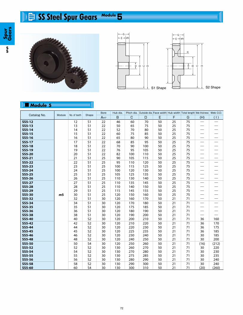
72
Catalog No. Module No. of teeth ShapeBore Hub dia. Pitch dia. Outside dia. Face width Hub width Total length Web thickness Web O.D.
AH7 B C D E F G (H) ( I )SS5-12SS5-13SS5-14SS5-15SS5-16
m5
1213141516
S1S1S1S1S1
2222222222
4650526065
6065707580
7075808590
5050505050
2525252525
7575757575
―――――
―――――
SS5-17SS5-18SS5-19SS5-20SS5-21
1718192021
S1S1S1S1S1
2222222225
6870768290
859095
100105
95100105110115
5050505050
2525252525
7575757575
―――――
―――――
SS5-22SS5-23SS5-24SS5-25SS5-26
2223242526
S1S1S1S1S1
2525252525
95100100105110
110115120125130
120125130135140
5050505050
2525252525
7575757575
―――――
―――――
SS5-27SS5-28SS5-29SS5-30SS5-32
2728293032
S1S1S1S1S1
2525252530
110110115120120
135140145150160
145150155160170
5050505050
2525252521
7575757571
―――――
―――――
SS5-34SS5-35SS5-36SS5-38SS5-40
3435363840
S1S1S1S1S2
3030303030
120120120120120
170175180190200
180185190200210
5050505050
2121212121
7171717171
――――36
――――
160SS5-42SS5-44SS5-45SS5-46SS5-48
4244454648
S2S2S2S2S2
3030303030
120120120120120
210220225230240
220230235240250
5050505050
2121212121
7171717171
3636363030
170175185185200
SS5-50SS5-52SS5-54SS5-55SS5-56
5052545556
S4S2S2S2S2
3030303030
120130130130130
250260270275280
260270280285290
5050505050
2121212121
7171717171
(16)30303030
(212)220230235240
SS5-58SS5-60
5860
S2S4
3030
130130
290300
300310
5050
2121
7171
30(20)
240(260)
SS Steel Spur Gears 5Module
Spur
G
ears
SS
■ Module 5
S2 ShapeS1 Shape

73
NOTE 1: The allowable torques shown in the table are calculated values according to the assumed usage conditions. Please see page 27 for more details.
NOTE 2: The backlash values shown in the table are the theoretical values of a pair of identical gears in mesh.
Allowable torque(N・m) NOTE 1 Allowable torque(kgf・m) Backlash
(mm)NOTE 2
Weight(kg)
Catalog No.Bending strength Surface durability Bending strength Surface durability
318365413462512
15.218.421.825.529.5
32.437.242.147.152.2
1.551.882.222.603.01
0.20~0.440.20~0.440.20~0.440.20~0.440.20~0.44
1.21 1.46 1.70 2.07 2.40
SS5-12SS5-13SS5-14SS5-15SS5-16
562614666718772
33.838.443.448.654.2
57.362.667.973.378.7
3.453.924.424.965.53
0.20~0.440.20~0.440.20~0.440.20~0.440.24~0.50
2.72 3.03 3.45 3.90 4.36
SS5-17SS5-18SS5-19SS5-20SS5-21
825879934989
1040
60.166.373.080.087.1
84.189.795.2
101106
6.136.777.458.168.88
0.24~0.500.24~0.500.24~0.500.24~0.500.24~0.50
4.83 5.33 5.69 6.23 6.79
SS5-22SS5-23SS5-24SS5-25SS5-26
11001160121012701380
94.4102110118136
112118124129141
9.6210.411.212.113.8
0.24~0.500.24~0.500.24~0.500.24~0.500.24~0.50
7.19 7.62 8.23 8.87 9.36
SS5-27SS5-28SS5-29SS5-30SS5-32
15001550161017301540
154164174195182
153158164176157
15.716.717.819.918.5
0.24~0.500.24~0.500.24~0.500.24~0.500.24~0.50
10.4 10.9 11.5 12.6 13.2
SS5-34SS5-35SS5-36SS5-38SS5-40
16301730178018301930
202223234246269
167177182187197
20.622.823.925.127.5
0.28~0.580.28~0.580.28~0.580.28~0.580.28~0.58
14.2 15.4 15.8 16.2 17.0
SS5-42SS5-44SS5-45SS5-46SS5-48
20302130222022702320
294320347361375
207217227232237
30.032.635.436.838.3
0.28~0.580.28~0.580.28~0.580.28~0.580.28~0.58
15.0 19.8 20.9 21.5 22.0
SS5-50SS5-52SS5-54SS5-55SS5-56
24202520
405435
247257
41.344.4
0.28~0.580.28~0.58
23.8 21.4
SS5-58SS5-60
Spur
G
ears
SS
Steel Spur Gears
* FD has the die-forged finish.
S4 Shape
Specifications
Precision grade
Gear teeth
Pressure angle
Material
Heat treatment
Standard full depth
20°
S45C
-
Tooth hardness
Surface treatment
Tooth surface finish
Secondary Operations
Less than 194HB
Black oxide
Cut
Bore
JIS N8 grade (JIS B1702-1: 1998) OLD JIS 4 grade (JIS B1702: 1976)
Datum reference surface for gear cutting
Possible

74
Catalog No. Module No. of teeth ShapeBore Hub dia. Pitch dia. Outside dia. Face width Hub width Total length Web thickness Web O.D.
AH7 B C D E F G H ISS6-12SS6-13SS6-14SS6-15SS6-16
m6
1213141516
S1S1S1S1S1
2525252525
5558607075
7278849096
849096
102108
6060606060
2828282828
8888888888
―――――
―――――
SS6-17SS6-18SS6-19SS6-20SS6-21
1718192021
S1S1S1S1S1
2525252528
788090
100105
102108114120126
114120126132138
6060606060
2828282828
8888888888
―――――
―――――
SS6-22SS6-23SS6-24SS6-25SS6-26
2223242526
S1S1S1S1S1
2828282828
110115120125130
132138144150156
144150156162168
6060606060
2828282828
8888888888
―――――
―――――
SS6-27SS6-28SS6-30SS6-32SS6-34
2728303234
S1S1S1S1S1
2828303030
135140150150150
162168180192204
174180192204216
6060606060
2828282323
8888888383
―――――
―――――
SS6-35SS6-36SS6-38SS6-40SS6-42
3536384042
S1S1S1S1S1
3030303040
150150150150150
210216228240252
222228240252264
6060606060
2323232323
8383838383
―――――
―――――
SS6-44SS6-45SS6-46SS6-48SS6-50
4445464850
S1S1S1S1S1
4040404040
150180180180180
264270276288300
276282288300312
6060606060
2323232323
8383838383
―――――
―――――
SS8-12SS8-13SS8-14SS8-15SS8-16
m8
1213141516
S1S1S1S1S1
2828282828
75808590
100
96104112120128
112120128136144
7575757575
3535353535
110110110110110
―――――
―――――
SS8-17SS8-18SS8-19SS8-20SS8-21
1718192021
S1S1S1S1S1
2828282830
105110120130140
136144152160168
152160168176184
7575757575
3535353535
110110110110110
―――――
―――――
SS8-22SS8-23SS8-24SS8-25SS8-26
2223242526
S1S1S1S1S1
3030303030
150155160170170
176184192200208
192200208216224
7575757575
3535353535
110110110110110
―――――
―――――
SS8-27SS8-28SS8-30
272830
S1S1S1
303030
170180180
216224240
232240256
757575
353535
110110110
―――
―――
SS10-15SS10-20SS10-25
m10152025
S1S1S1
303040
115165200
150200250
170220270
909090
404040
130130130
―――
―――
SS Steel Spur Gears 6~10Modules
Spur
G
ears
SS
■ Module 6, 8, 10S1 Shape

75
NOTE 1: The allowable torques shown in the table are calculated values according to the assumed usage conditions. Please see page 27 for more details.
NOTE 2 : The backlash values shown in the table are the theoretical values of a pair of identical gears in mesh.
Specifications
Precision grade
Gear teeth
Pressure angle
Material
Heat treatment
Standard full depth
20°
S45C
-
Tooth hardness
Surface treatment
Tooth surface finish
Secondary Operations
Less than 194HB
Black oxide
Cut
Bore
JIS N8 grade (JIS B1702-1: 1998) OLD JIS 4 grade (JIS B1702: 1976)
Datum reference surface for gear cutting
Possible
Allowable torque(N・m) NOTE 1 Allowable torque(kgf・m) Backlash
(mm)NOTE 2
Weight(kg)
Catalog No.Bending strength Surface durability Bending strength Surface durability
550631713798884
26.832.438.444.952
56.164.372.881.490.2
2.733.313.924.585.3
0.22~0.480.22~0.480.22~0.480.22~0.480.22~0.48
2.10 2.49 2.89 3.50 4.04
SS6-12SS6-13SS6-14SS6-15SS6-16
9721060115012401330
59.667.776.485.995.9
99.1108117127136
6.076.97.798.759.78
0.22~0.480.22~0.480.22~0.480.22~0.480.26~0.56
4.56 5.08 5.87 6.71 7.35
SS6-17SS6-18SS6-19SS6-20SS6-21
14301520161017101800
107118129142154
145155165174184
10.91213.214.515.7
0.26~0.560.26~0.560.26~0.560.26~0.560.26~0.56
8.11 8.90 9.73
10.6 11.5
SS6-22SS6-23SS6-24SS6-25SS6-26
19002000219019902150
167181209200228
194204223203220
1718.421.320.423.2
0.26~0.560.26~0.560.26~0.560.26~0.560.26~0.56
12.4 13.4 15.4 16.4 18.1
SS6-27SS6-28SS6-30SS6-32SS6-34
22402320249026502820
242258289323359
228237254271288
24.726.329.53336.6
0.26~0.560.26~0.560.26~0.560.26~0.560.30~0.64
19.0 20.0 22.0 24.0 25.9
SS6-35SS6-36SS6-38SS6-40SS6-42
29903080316033303500
397416436478522
305314322340357
40.542.544.548.853.2
0.30~0.640.30~0.640.30~0.640.30~0.640.30~0.64
28.2 30.7 32.0 34.5 37.1
SS6-44SS6-45SS6-46SS6-48SS6-50
12201400159017701970
62.675.288.9
104121
125143162181200
6.397.669.06
10.612.3
0.28~0.580.28~0.580.28~0.580.28~0.580.28~0.58
4.94 5.85 6.83 7.87 9.20
SS8-12SS8-13SS8-14SS8-15SS8-16
21602360256027602960
139158178200223
220240261281302
14.116.118.220.422.8
0.28~0.580.28~0.580.28~0.580.28~0.580.32~0.66
10.4 11.7 13.3 15.0 16.7
SS8-17SS8-18SS8-19SS8-20SS8-21
31703380299031603340
248273250273297
323344305323341
25.327.925.527.830.3
0.32~0.660.32~0.660.32~0.660.32~0.660.32~0.66
18.6 20.2 22.0 24.1 25.6
SS8-22SS8-23SS8-24SS8-25SS8-26
352037004060
322348404
359377414
32.835.541.2
0.32~0.660.32~0.660.32~0.66
27.2 29.6 33.0
SS8-27SS8-28SS8-30
333043105930
203323529
339440605
20.73354
0.34~0.680.34~0.680.36~0.76
15.0 28.2 43.3
SS10-15SS10-20SS10-25
Spur
G
ears
SS
Steel Spur Gears

76
NOTE 1: Please design the maximum bore so that the tooth strength is less than the strength of remaining material.
Catalog No. Module No. of teeth ShapeBore Hub dia. Pitch dia. Outside dia. Face width Web thickness Web O.D.
AH7 NOTE 1 B C D E H ISSA1-20SSA1-24SSA1-25SSA1-28SSA1-30
m1
2024252830
S5S5S5S5S5
88888
―――――
2024252830
2226273032
1010101010
―――――
―――――
SSA1-32SSA1-35SSA1-36SSA1-40SSA1-45
3235364045
S5S5S5S5S5
88888
―――――
3235364045
3437384247
1010101010
―――――
―――――
SSA1-48SSA1-50SSA1-55SSA1-56SSA1-60
4850555660
S5S5S5S5S5
810101010
―――――
4850555660
5052575862
1010101010
―――――
―――――
SSA1-70SSA1-80SSA1-100SSA1-120
7080
100120
S5S5S5S5
10101010
――――
7080
100120
7282
102122
10101010
――――
――――
SSA1.5-20SSA1.5-24SSA1.5-25SSA1.5-28SSA1.5-30
m1.5
2024252830
S5S5S5S5S5
1010101010
―――――
303637.54245
333940.54548
1515151515
―――――
―――――
SSA1.5-32SSA1.5-35SSA1.5-36SSA1.5-40SSA1.5-45
3235364045
S5S5S5S5S5
1010101515
―――――
4852.5546067.5
5155.5576370.5
1515151515
―――――
―――――
SSA1.5-48SSA1.5-50SSA1.5-55SSA1.5-56SSA1.5-60
4850555660
S5S5S5S5S5
1515151515
―――――
727582.58490
757885.58793
1515151515
―――――
―――――
SSA1.5-70SSA1.5-80SSA1.5-100
7080
100
S5S5S6
151515
――70
105120150
108123153
151515
――9
――
125
SSA Steel Hubless Spur Gears 1~1.5Modules
Spur
G
ears
SSA
■ Module 1
S5 Shape
■ Module 1.5
S6 Shape

77
NOTE 2: The allowable torques shown in the table are calculated values according to the assumed usage conditions. Please see page 27 for more details.
NOTE 3: The backlash values shown in the table are the theoretical values of a pair of identical gears in mesh.
Specifications
Precision grade
Gear teeth
Pressure angle
Material
Heat treatment
Standard full depth
20°
S45C
-
Tooth hardness
Surface treatment
Tooth surface finish
Secondary Operations
Less than 194HB
Black oxide
Cut
Bore
JIS N8 grade (JIS B1702-1: 1998) OLD JIS 4 grade (JIS B1702: 1976)
Datum reference surface for gear cutting
Possible
Allowable torque(N・m) NOTE 2 Allowable torque(kgf・m) Backlash
(mm) NOTE 3
Weight(kg)
Catalog No.Bending strength Surface durability Bending strength Surface durability
5.757.477.919.24
10.1
0.330.490.540.680.79
0.590.760.810.941.03
0.0330.0500.0550.0700.081
0.08~0.180.08~0.180.08~0.180.08~0.180.08~0.18
0.0210.032 0.035 0.044 0.052
SSA1-20SSA1-24SSA1-25SSA1-28SSA1-30
11.112.412.914.717.1
0.901.091.161.451.86
1.131.271.311.501.74
0.0920.110.120.150.19
0.08~0.180.08~0.180.08~0.180.08~0.180.08~0.18
0.059 0.072 0.076 0.095 0.12
SSA1-32SSA1-35SSA1-36SSA1-40SSA1-45
18.519.521.822.324.2
2.132.322.832.943.40
1.891.982.232.282.47
0.220.240.290.300.35
0.08~0.180.08~0.180.08~0.180.08~0.180.08~0.18
0.14 0.15 0.18 0.19 0.22
SSA1-48SSA1-50SSA1-55SSA1-56SSA1-60
29.133.943.753.5
4.706.239.97
14.7
2.963.464.455.45
0.480.631.021.50
0.08~0.180.08~0.180.08~0.180.08~0.18
0.30 0.39 0.61 0.88
SSA1-70SSA1-80SSA1-100SSA1-120
19.425.226.731.234.2
1.151.731.902.412.79
1.982.572.723.183.49
0.120.180.190.250.28
0.10~0.220.12~0.260.12~0.260.12~0.260.12~0.26
0.074 0.11 0.12 0.15 0.18
SSA1.5-20SSA1.5-24SSA1.5-25SSA1.5-28SSA1.5-30
37.341.943.549.857.7
3.193.854.095.106.53
3.804.284.435.075.88
0.330.390.420.520.67
0.12~0.260.12~0.260.12~0.260.12~0.260.14~0.32
0.20 0.25 0.26 0.31 0.40
SSA1.5-32SSA1.5-35SSA1.5-36SSA1.5-40SSA1.5-45
62.465.773.775.381.8
7.478.159.96
10.412.0
6.376.697.517.688.34
0.760.831.021.061.22
0.14~0.320.14~0.320.14~0.320.14~0.320.14~0.32
0.46 0.50 0.61 0.63 0.73
SSA1.5-48SSA1.5-50SSA1.5-55SSA1.5-56SSA1.5-60
98.0114147
16.622.035.5
10.011.715.0
1.692.243.62
0.14~0.320.14~0.320.18~0.38
1.00 1.31 1.72
SSA1.5-70SSA1.5-80SSA1.5-100
Spur
G
ears
SSA
Steel, Hubless Spur Gears

78
NOTE 1: Please design the maximum bore so that the tooth strength is less than the strength of remaining material.
Catalog No. Module No. of teeth ShapeBore Hub dia. Pitch dia. Outside dia. Face width Web thickness Web O.D.
AH7 B C D E H ISSA2-20SSA2-24SSA2-25SSA2-28SSA2-30
m2
2024252830
S5S5S5S5S5
1212121515
―――――
4048505660
4452546064
2020202020
―――――
―――――
SSA2-32SSA2-35SSA2-36SSA2-40SSA2-45
3235364045
S5S5S5S5S5
1515151818
―――――
6470728090
6874768494
2020202020
―――――
―――――
SSA2-48SSA2-50SSA2-55SSA2-56SSA2-60
4850555660
S5S5S5S5S5
1818181818
―――――
96100110112120
100104114116124
2020202020
―――――
―――――
SSA2-70SSA2-80SSA2-100
7080
100
S5S6S6
181818
―7090
140160200
144164204
202020
―1212
―136176
SSA2.5-20SSA2.5-24SSA2.5-25SSA2.5-28SSA2.5-30
m2.5
2024252830
S5S5S5S5S5
1515151818
―――――
506062.57075
556567.57580
2525252525
―――――
―――――
SSA2.5-32SSA2.5-35SSA2.5-36SSA2.5-40SSA2.5-45
3235364045
S5S5S5S5S5
1818182222
―――――
8087.590
100112.5
8592.595
105117.5
2525252525
―――――
―――――
SSA2.5-48SSA2.5-50SSA2.5-55SSA2.5-56SSA2.5-60
4850555660
S5S5S5S5S6
2222222222
――――70
120125137.5140150
125130142.5145155
2525252525
――――15
――――
121
SSA2.5-70SSA2.5-80
7080
S6S6
2222
8090
175200
180205
2525
1515
146171
SSA Steel Hubless Spur Gears 2~2.5Modules
Spur
G
ears
SSA
■ Module 2
S5 Shape S6 Shape
■ Module 2.5

79
NOTE 2: The allowable torques shown in the table are calculated values according to the assumed usage conditions. Please see page 27 for more details.
NOTE 3: The backlash values shown in the table are the theoretical values of a pair of identical gears in mesh.
Allowable torque(N・m) Allowable torque(kgf・m) Backlash
(mm)Weight(kg)
Catalog No.Bending strength Surface durability Bending strength Surface durability
46.059.863.373.981.1
2.834.244.645.896.80
4.696.096.457.548.27
0.290.430.470.600.69
0.12~0.260.14~0.300.14~0.300.14~0.300.14~0.30
0.18 0.27 0.29 0.36 0.42
SSA2-20SSA2-24SSA2-25SSA2-28SSA2-30
88.499.3
103118137
7.789.399.96
12.516.0
9.0110.110.512.013.9
0.790.961.021.271.63
0.14~0.300.14~0.300.14~0.300.14~0.300.18~0.36
0.48 0.58 0.61 0.75 0.96
SSA2-32SSA2-35SSA2-36SSA2-40SSA2-45
148156175179194
18.319.924.425.329.3
15.115.917.818.219.8
1.872.032.482.582.99
0.18~0.360.18~0.360.18~0.360.18~0.360.18~0.36
1.10 1.19 1.45 1.51 1.74
SSA2-48SSA2-50SSA2-55SSA2-56SSA2-60
232271291
40.854.372.7
23.727.729.7
4.165.537.42
0.18~0.360.18~0.360.20~0.44
2.38 2.55 3.90
SSA2-70SSA2-80SSA2-100
89.8117124144159
5.668.479.26
11.713.6
9.1611.912.614.716.2
0.580.860.941.201.39
0.14~0.280.16~0.340.16~0.340.16~0.340.16~0.34
0.35 0.52 0.57 0.71 0.82
SSA2.5-20SSA2.5-24SSA2.5-25SSA2.5-28SSA2.5-30
173194201230267
15.618.820.024.931.9
17.619.820.523.527.2
1.591.922.042.543.26
0.16~0.340.16~0.340.16~0.340.16~0.340.18~0.40
0.94 1.13 1.20 1.47 1.88
SSA2.5-32SSA2.5-35SSA2.5-36SSA2.5-40SSA2.5-45
289304341349379
36.740.049.151.059.1
29.531.034.835.638.6
3.744.085.015.206.03
0.18~0.400.18~0.400.18~0.400.18~0.400.18~0.40
2.14 2.33 2.84 2.95 2.93
SSA2.5-48SSA2.5-50SSA2.5-55SSA2.5-56SSA2.5-60
454441
82.190.9
46.345.0
8.379.27
0.18~0.400.18~0.40
3.89 4.99
SSA2.5-70SSA2.5-80
Spur
G
ears
SSA
Specifications
Precision grade
Gear teeth
Pressure angle
Material
Heat treatment
Standard full depth
20°
S45C
-
Tooth hardness
Surface treatment
Tooth surface finish
Secondary Operations
Less than 194HB
Black oxide
Cut
Bore
JIS N8 grade (JIS B1702-1: 1998) OLD JIS 4 grade (JIS B1702: 1976)
Datum reference surface for gear cutting
Possible
Steel, Hubless Spur Gears

80
NOTE 1: Please design the maximum bore so that the tooth strength is less than the strength of remaining material.
Catalog No. Module No. of teeth ShapeBore Hub dia. Pitch dia. Outside dia. Face width Web thickness Web O.D.
AH7 B C D E H ISSA3-20SSA3-24SSA3-25SSA3-28SSA3-30
m3
2024252830
S5S5S5S5S5
1515152020
―――――
6072758490
6678819096
3030303030
―――――
―――――
SSA3-32SSA3-35SSA3-36SSA3-40SSA3-45
3235364045
S5S5S5S5S5
2020202525
―――――
96105108120135
102111114126141
3030303030
―――――
―――――
SSA3-48SSA3-50SSA3-55SSA3-56SSA3-60
4850555660
S5S6S6S6S6
2525252525
―70808090
144150165168180
150156171174186
3030303030
―18181818
―116131134146
SSA3-70SSA3-80
7080
S6S6
2525
9090
210240
216246
3030
1818
176205
SSA4-20SSA4-24SSA4-25SSA4-28SSA4-30
m4
2024252830
S5S5S5S5S5
2020202525
―――――
8096
100112120
88104108120128
4040404040
―――――
―――――
SSA4-32SSA4-35SSA4-36SSA4-40SSA4-45
3235364045
S5S5S5S6S6
2525253030
―――80
100
128140144160180
136148152168188
4040404040
―――2626
―――
118138
SSA4-48SSA4-50SSA4-55SSA4-56SSA4-60
4850555660
S6S6S6S6S6
3030303030
100100110110120
192200220224240
200208228232248
4040404040
2626262626
150158178182198
SSA5-20SSA5-24SSA5-25SSA5-28SSA5-30
m5
2024252830
S5S5S5S5S5
2222222525
―――――
100120125140150
110130135150160
5050505050
―――――
―――――
SSA5-32SSA5-35SSA5-36SSA5-40SSA5-45
3235364045
S5S5S5S6S6
2525253030
―――
100120
160175180200225
170185190210235
5050505050
―――3636
―――
160185
SSA5-48SSA5-50
4850
S6S6
3030
120130
240250
250260
5050
3636
200210
SSA Steel Hubless Spur Gears 3~5Modules
Spur
G
ears
SSA
■ Module 3, 4 ,5S5 Shape S6 Shape

81
NOTE 2: The allowable torques shown in the table are calculated values according to the assumed usage conditions. Please see page 27 for more details.
NOTE 3: The backlash values shown in the table are the theoretical values of a pair of identical gears in mesh.
Allowable torque(N・m) Allowable torque(kgf・m) Backlash
(mm)Weight(kg)
Catalog No.Bending strength Surface durability Bending strength Surface durability
155202214250274
9.9514.916.320.724.0
15.820.621.825.427.9
1.021.521.662.112.44
0.14~0.320.18~0.380.18~0.380.18~0.380.18~0.38
0.62 0.92 1.00 1.23 1.42
SSA3-20SSA3-24SSA3-25SSA3-28SSA3-30
298335348398461
27.433.135.244.056.6
30.434.235.540.647
2.803.383.594.495.78
0.18~0.380.18~0.380.18~0.380.18~0.380.20~0.44
1.63 1.97 2.08 2.55 3.26
SSA3-32SSA3-35SSA3-36SSA3-40SSA3-45
500525590602654
65.070.986.990.3
105
50.953.660.161.466.7
6.637.238.869.21
10.7
0.20~0.440.20~0.440.20~0.440.20~0.440.20~0.44
3.72 3.60 4.34 4.47 5.14
SSA3-48SSA3-50SSA3-55SSA3-56SSA3-60
654763
121162
66.677.8
12.416.5
0.20~0.440.20~0.44
6.64 8.37
SSA3-70SSA3-80
368478506591649
24.336.439.950.658.7
37.548.851.660.366.2
2.483.724.075.165.98
0.18~0.380.20~0.440.20~0.440.20~0.440.20~0.44
1.48 2.17 2.37 2.94 3.40
SSA4-20SSA4-24SSA4-25SSA4-28SSA4-30
707795825943
1090
67.481.686.7
109139
72.181.184.196.2
112
6.878.328.84
11.114.2
0.20~0.440.20~0.440.20~0.440.20~0.440.24~0.52
3.89 4.68 4.96 5.70 7.29
SSA4-32SSA4-35SSA4-36SSA4-40SSA4-45
9871040116011901290
133146179186215
101106119121132
13.614.818.218.922.0
0.24~0.520.24~0.520.24~0.520.24~0.520.24~0.52
8.12 8.70
10.4 10.7 12.3
SSA4-48SSA4-50SSA4-55SSA4-56SSA4-60
718934989
11601270
48.673.080.0
102118
73.395.2
101118129
4.967.458.16
10.412.1
0.20~0.440.24~0.500.24~0.500.24~0.500.24~0.50
2.93 4.29 4.67 5.85 6.74
SSA5-20SSA5-24SSA5-25SSA5-28SSA5-30
13801550161015401780
136164174182234
141158164157182
13.816.717.818.523.9
0.24~0.500.24~0.500.24~0.500.24~0.500.28~0.58
7.70 9.25 9.80
11.1 14.0
SSA5-32SSA5-35SSA5-36SSA5-40SSA5-45
19302030
269294
197207
27.530.0
0.28~0.580.28~0.58
15.7 17.1
SSA5-48SSA5-50
Spur
G
ears
SSA
Steel, Hubless Spur Gears
Specifications
Precision grade
Gear teeth
Pressure angle
Material
Heat treatment
Standard full depth
20°
S45C
-
Tooth hardness
Surface treatment
Tooth surface finish
Secondary Operations
Less than 194HB
Black oxide
Cut
Bore
JIS N8 grade (JIS B1702-1: 1998) OLD JIS 4 grade (JIS B1702: 1976)
Datum reference surface for gear cutting
Possible

SSY0.8-20 SSY0.8-25 SSY0.8-30 SSY0.8-40 SSY0.8-50
0.80.80.80.80.8
SSY1- 12 SSY1- 14 SSY1- 15 SSY1- 16 SSY1- 18SSY1- 20 SSY1- 24 SSY1- 25 SSY1- 28 SSY1- 30SSY1- 32 SSY1- 35 SSY1- 36 SSY1- 40 SSY1- 45SSY1- 48 SSY1- 50 SSY1- 55 SSY1- 56 SSY1- 60SSY1- 64 SSY1- 65 SSY1- 70 SSY1- 72 SSY1- 75SSY1- 80 SSY1- 85 SSY1- 90 SSY1- 95 SSY1- 96SSY1-100 SSY1-110 SSY1-120
111111111111111111111111111111111
012014015 016 018020024025028 030032035036040 045048050055056060064065070072075080085090 095 096100110120
05 05 06060606 06 06060606 0606080808 08080808080808080810 10 10101010 1010
09 1112 13 1416 1616 162525 2525 282828 282828 3535 353535354040404040505050
012014 015 016 018020024025028 030032035036040 045048050055056060064065070072075080085090 095096100110120
014016 017 018 020022026 027030 032034037038042 047050052 057058062066067072074 077082087092097098102112122
666666666666666666666666666666666
888888888888888888888888888888888
141414141414141414141414141414141414141414141414141414141414141414
—————
—————
—————
—————
—————
—————
———
—————
—————
—————
—————
—————
—————
———
2025304050
5 5 555
13.5 17.020.025.025.0
1620243240
17.621.625.633.641.6
44444
88888
1212121212
—————
—————
82
CAUTION: The gears with wider face widths such as SS and SSA series can be used as the mating gears to these.NOTE 1: Due to the thin face width, if you wish to perform secondary operations on these gears, please use care to avoid side run out and deformation. If you heat treat them, there is the possibility of warping these gears.
S1 Shape
SSY Steel Thin Face Spur Gears 0.8~1Modules
Spur
G
ears
SSY
■ Module 0.8
Catalog
No.
Module
z
No. of teeth
AH7 B C
Bore Pitch dia.Hub dia.
D E
Outside dia. Face width NOTE 1
F G H I
Hub width Total length Web thickness Web O.D.
m
■ Module 1

S1S1S1S1S1S1S1S1S1S1S1S1S1S1S1S1S1S1S1S1S1S1S1S1S1S1S1S1S1S1S1S1S1
01.527 01.982 02.216 02.457 02.94603.448 04.482 04.744 05.54506.08406.629 07.453 07.730 08.844 10.25011.100 11.670 13.100 13.390 14.53015.690 15.970 17.430 18.000 18.88020.340 21.800 23.260 24.72025.02026.190 29.140 32.080
0.0686 0.0961 0.1118 0.1275 0.16180.2010 0.2952 0.3217 0.4089 0.47370.5423 0.6551 0.6963 0.8698 1.11501.2770 1.3920 1.6990 1.7650 2.04002.3360 2.4120 2.8170 2.9890 3.25903.7350 4.2460 4.7900 5.3690 5.48905.9810 7.30908.7990
(0.1557) (0.2021) (0.2260) (0.2505) (0.3004) (0.3516) (0.4570) (0.4838) (0.5654) (0.6204) (0.6760) (0.7600) (0.7882) (0.9018) (1.0450) (1.1320) (1.1900) (1.3360) (1.3650) (1.4820) (1.6000) (1.6290) (1.7770) (1.8360) (1.9250) (2.0740) (2.2230) (2.3720) (2.5210) (2.5510)
(2.6710) (2.9710) (3.2710)
(0.0070) (0.0098) (0.0114) (0.0130) (0.0165) (0.0205) (0.0301) (0.0328) (0.0417) (0.0483) (0.0553) (0.0668) (0.0710) (0.0887) (0.1137) (0.1302) (0.1419) (0.1733) (0.1800) (0.2080) (0.2382) (0.2460) (0.2873) (0.3048) (0.3323) (0.3809) (0.4330) (0.4885) (0.5475) (0.5597)
(0.6099) (0.7453) (0.8973)
0.08 ~ 0.18 0.08 ~ 0.18 0.08 ~ 0.18 0.08 ~ 0.18 0.08 ~ 0.180.08 ~ 0.18 0.08 ~ 0.18 0.08 ~ 0.18 0.08 ~ 0.18 0.08 ~ 0.180.08 ~ 0.18 0.08 ~ 0.18 0.08 ~ 0.18 0.08 ~ 0.18 0.08 ~ 0.180.08 ~ 0.18 0.08 ~ 0.18 0.08 ~ 0.18 0.08 ~ 0.18 0.08 ~ 0.180.08 ~ 0.18 0.08 ~ 0.18 0.08 ~ 0.18 0.08 ~ 0.18 0.08 ~ 0.180.08 ~ 0.18 0.08 ~ 0.18 0.08 ~ 0.18 0.08 ~ 0.18 0.08 ~ 0.180.08 ~ 0.18 0.08 ~ 0.18 0.08 ~ 0.18
0.01 0.01 0.01 0.02 0.020.02 0.03 0.03 0.04 0.060.06 0.07 0.08 0.09 0.110.12 0.13 0.14 0.15 0.190.21 0.21 0.24 0.25 0.260.31 0.34 0.370.400.410.48 0.56 0.65
SSY1- 12 SSY1- 14 SSY1- 15 SSY1- 16 SSY1- 18SSY1- 20 SSY1- 24 SSY1- 25 SSY1- 28SSY1- 30SSY1- 32 SSY1- 35 SSY1- 36 SSY1- 40 SSY1- 45SSY1- 48SSY1- 50SSY1- 55 SSY1- 56SSY1- 60SSY1- 64 SSY1- 65 SSY1- 70 SSY1- 72 SSY1- 75SSY1- 80SSY1- 85SSY1- 90 SSY1- 95SSY1- 96SSY1-100SSY1-110SSY1-120
S1S1S1S1S1
1.4712.0252.5963.7744.980
0.0850.1340.1970.3620.580
(0.150) (0.207) (0.265) (0.385) (0.508)
(0.0087) (0.0137) (0.0201) (0.0369) (0.0591)
0 ~ 0.10 0 ~ 0.10 0 ~ 0.10 0 ~ 0.10 0 ~ 0.10
0.0140.0230.0320.0540.068
SSY0.8-20 SSY0.8-25 SSY0.8-30 SSY0.8-40SSY0.8-50
83
*The blue catalog numbers indicate the new products.NOTE 2: The allowable torques shown in the table are calculated values according to the assumed usage conditions.
Please see page 27 for more details. NOTE 3: The backlash values shown in the table are the theoretical values of a pair of identical gears in mesh.
Spur
G
ears
SSY
Steel, Thin Face Spur Gears
Catalog
No.Backlash (mm)
NOTE 3Shape
Bending strength Surface durability Bending strength Surface durability
Allowable torque (kgf.m) Weight
(kgf)
Specifications
Precision grade
Gear teeth
Pressure angle
Material
Heat treatment
Standard full depth
20°
S45C
-
Tooth hardness
Surface treatment
Tooth surface finish
Secondary Operations
Less than 194HB
Black oxide
Cut
Bore
JIS N8 grade (JIS B1702-1: 1998) OLD JIS 4 grade (JIS B1702: 1976)
Datum reference surface for gear cutting
Possible
Allowable torque (N.m) NOTE 2

SSY1.25- 12 SSY1.25- 14 SSY1.25- 15 SSY1.25- 16 SSY1.25- 18SSY1.25- 20 SSY1.25- 24 SSY1.25- 25 SSY1.25- 28 SSY1.25- 30SSY1.25- 32 SSY1.25- 35 SSY1.25- 36 SSY1.25- 40 SSY1.25- 45SSY1.25- 48 SSY1.25- 50 SSY1.25- 55 SSY1.25- 56 SSY1.25- 60SSY1.25- 64 SSY1.25- 65 SSY1.25- 70 SSY1.25- 72 SSY1.25- 75SSY1.25- 80 SSY1.25- 85 SSY1.25- 90 SSY1.25- 95 SSY1.25- 96SSY1.25-100
1.251.251.251.251.25
1.251.251.251.251.251.251.251.251.251.251.251.251.251.251.251.25
012014 015 016018020024 025 028030032035036 040 045048050055056060064 065 070072 075080085090095 096100
05 05 06 06 0608 08 08 08 10101010101010121212 12121215 1515151515151515
111315 16 1820 2424283030 3636404040 45 45 45 5050 50555555606065656565
015.00017.50018.75020.00022.50025.00 030.00 031.25 035.00037.50040.00043.75 045.00050.00056.25060.00 062.50 068.75 070.00075.00080.00 081.25 087.50090.00 093.75100.00106.25 112.50 118.75 120.00125.00
017.50 020.00 021.25 022.50025.00027.50 032.50 033.75037.50040.00042.50046.25 047.50 052.50 058.75062.50065.00071.25072.50 077.50082.50 083.75 090.00 092.50 096.25102.50108.75115.00121.25122.50127.50
8888888888888888888888888888888
10101010101010101010101010101010101010101010101010101010101010
18181818181818181818181818181818181818181818181818181818181818
—————
—————
—————
—————
—————
—————
—
—————
—————
—————
—————
—————
—————
—
84
NOTE 1: Due to the thin face width, if you wish to perform secondary operations on these gears, please use care to avoid side run out and deformation. If you heat treat them, there is the possibility of warping these gears.
S1 Shape
1.251.251.251.251.251.251.251.251.251.25
SSY Steel Thin Face Spur Gears 1.25Module
Spur
G
ears
SSY
■ Module 1.25
Catalog
No.
Module
z
No. of teeth
AH7 B C
Bore Pitch dia.Hub dia.
D E
Outside dia. Face width NOTE 1
F G H I
Hub width Total length Web thickness Web O.D.
m

Steel, Thin Face Spur Gears
S1S1S1S1S1S1S1S1S1S1S1S1 S1 S1S1S1 S1S1S1S1S1 S1S1 S1S1S1S1S1S1S1S1
03.181 04.129 04.618 05.117 06.13707.183 09.337 09.885 11.550 12.68013.810 15.520 16.100 18.430 21.36023.120 24.310 27.290 27.890 30.28032.690 33.290 36.300 37.520 39.33042.370 45.410 48.460 51.510 52.12054.570
00.1442 00.2010 00.2334 00.2687 00.343200.4295 00.6315 00.6884 00.8738 01.011001.1590 01.4000 01.4870 01.8550 02.376002.7200 02.9640 03.6170 03.7560 04.345004.9810 05.1460 06.0180 06.3870 06.962007.9750 09.0590 10.2200 11.4700 11.730012.8100
(0.3244)(0.4210)(0.4709)(0.5218)(0.6258)
(2.3580)(2.4790)(2.7830)(2.8440)(3.0880)(3.3330)(3.3395)(3.7020)(3.8260)(4.0110)(4.3210)(4.6310)(4.9420)(5.2530)(5.3150)
(5.5650)
(0.0147) (0.0205) (0.0238) (0.0274) (0.0350) (0.0438) (0.0644) (0.0702) (0.0891) (0.1031)
(0.1182) (0.1428) (0.1516) (0.1892) (0.2423) (0.2774) (0.3022) (0.3688) (0.3830) (0.4431)
(0.5079) (0.5248) (0.6137) (0.6513) (0.7099) (0.8132) (0.9238) (1.0420) (1.1700) (1.1960)
(1.3060)
0.08 ~ 0.18 0.08 ~ 0.18 0.08 ~ 0.18 0.08 ~ 0.18 0.08 ~ 0.180.08 ~ 0.18 0.12 ~ 0.22 0.12 ~ 0.22 0.12 ~ 0.22 0.12 ~ 0.220.12 ~ 0.22 0.12 ~ 0.22 0.12 ~ 0.22 0.12 ~ 0.22 0.12 ~ 0.260.12 ~ 0.26 0.12 ~ 0.26 0.12 ~ 0.26 0.12 ~ 0.26 0.12 ~ 0.260.12 ~ 0.26 0.12 ~ 0.26 0.12 ~ 0.26 0.12 ~ 0.26 0.12 ~ 0.260.12 ~ 0.26 0.16 ~ 0.32 0.16 ~ 0.32 0.16 ~ 0.32 0.16 ~ 0.32 0.16 ~ 0.32
0.02 0.02 0.03 0.03 0.040.05 0.07 0.08 0.100.11 0.12 0.16 0.17 0.21 0.240.26 0.30 0.34 0.35 0.420.45 0.46 0.54 0.56 0.590.69 0.75 0.86 0.93 0.941.00
SSY1.25- 12 SSY1.25- 14 SSY1.25- 15 SSY1.25- 16 SSY1.25- 18SSY1.25- 20 SSY1.25- 24 SSY1.25- 25 SSY1.25- 28 SSY1.25- 30SSY1.25- 32SSY1.25- 35 SSY1.25- 36 SSY1.25- 40 SSY1.25- 45SSY1.25- 48 SSY1.25- 50 SSY1.25- 55 SSY1.25- 56 SSY1.25- 60SSY1.25- 64 SSY1.25- 65 SSY1.25- 70 SSY1.25- 72 SSY1.25- 75SSY1.25- 80 SSY1.25- 85 SSY1.25- 90 SSY1.25- 95 SSY1.25- 96SSY1.25-100
85
NOTE 2: The allowable torques shown in the table are calculated values according to the assumed usage conditions. Please see page 27 for more details.
NOTE 3: The backlash values shown in the table are the theoretical values of a pair of identical gears in mesh.
(0.7325)(0.9521)(1.0080)(1.1780)(1.2930)
(1.4080)(1.5830)(1.6420)(1.8790)(2.1780)
Spur
G
ears
SSY
Catalog
No.Backlash (mm)
NOTE 3Shape
Bending strength Surface durability Bending strength Surface durability
Allowable torque (kgf.m) Weight
(kgf)Allowable torque (N.m) NOTE 2
Specifications
Precision grade
Gear teeth
Pressure angle
Material
Heat treatment
Standard full depth
20°
S45C
-
Tooth hardness
Surface treatment
Tooth surface finish
Secondary Operations
Less than 194HB
Black oxide
Cut
Bore
JIS N8 grade (JIS B1702-1: 1998) OLD JIS 4 grade (JIS B1702: 1976)
Datum reference surface for gear cutting
Possible

86
NOTE 1: Due to the thin face width, if you wish to perform secondary operations on these gears, please use care to avoid side run out and deformation. If you heat treat them, there is the possibility of warping these gears.NOTE 2: The allowable torques shown in the table are calculated values according to the assumed usage conditions. Please see page 27 for more details.
S5 Shape
Catalog No. Module No. of teeth ShapeBore Pitch dia. Outside dia. Face width NOTE 1 Allowable torque(N・m) NOTE 2 Allowable torque(kgf・m)AH7 C D E Bending strength Surface durability Bending strength Surface durability
SSAY1-20SSAY1-24SSAY1-25SSAY1-28SSAY1-30
m1
2024252830
S5S5S5S5S5
66666
2024252830
2226273032
66666
3.45 4.48 4.74 5.55 6.08
0.20 0.30 0.32 0.41 0.47
0.35 0.46 0.48 0.57 0.62
0.021 0.030 0.033 0.042 0.048
SSAY1-32SSAY1-35SSAY1-36SSAY1-40SSAY1-45
3235364045
S5S5S5S5S5
66666
3235364045
3437384247
66666
6.63 7.45 7.73 8.84
10.3
0.54 0.66 0.70 0.87 1.12
0.68 0.76 0.79 0.90 1.05
0.055 0.067 0.071 0.089 0.11
SSAY1-48SSAY1-50SSAY1-55SSAY1-56SSAY1-60
4850555660
S5S5S5S5S5
68888
4850555660
5052575862
66666
11.1 11.7 13.1 13.4 14.5
1.28 1.39 1.70 1.77 2.04
1.13 1.19 1.34 1.37 1.48
0.13 0.14 0.17 0.18 0.21
SSAY1-70SSAY1-80SSAY1-100
7080
100
S5S5S5
81010
7080
100
7282
102
666
17.4 20.3 26.2
2.82 3.74 5.98
1.78 2.07 2.67
0.29 0.38 0.61
SSAY1.25-20 SSAY1.25-24 SSAY1.25-25 SSAY1.25-28 SSAY1.25-30
m1.25
2024252830
S5S5S5S5S5
8888
10
25 30 31.2535 37.5
27.532.5 33.75 37.5 40
88888
7.1839.3379.885
11.5512.68
0.4295 0.6315 0.6884 0.8738 1.011
0.7325 0.9521 1.008 1.178 1.293
0.0438 0.0644 0.0702 0.0891 0.1031
SSAY1.25-32 SSAY1.25-35 SSAY1.25-36 SSAY1.25-40 SSAY1.25-45
3235364045
S5S5S5S5S5
1010101010
40 43.75 45 50 56.25
42.5 46.25 47.5 52.5 58.75
88888
13.8115.5216.118.43 21.36
1.1591.4001.4871.8552.376
1.408 1.583 1.642 1.879 2.178
0.11820.14280.15160.18920.2423
SSAY1.25-48 SSAY1.25-50 SSAY1.25-55 SSAY1.25-56 SSAY1.25-60
4850555660
S5S5S5S5S5
1012121212
60 62.50 68.75 70 75
62.5 65 71.25 72.577.5
88888
23.1224.31 27.29 27.89 30.28
2.72 2.964 3.6173.7564.345
2.3582.479 2.783 2.844 3.088
0.2774 0.3022 0.3688 0.3830 0.4431
SSAY1.25-70 SSAY1.25-80 SSAY1.25-100
7080
100
S5S5S5
151515
87.5 100125
90102.5127.5
888
36.3 42.37 54.57
6.018 7.975
12.81
3.702 4.321 5.565
0.6137 0.8132 1.3060
SSAY Steel, Hubless, Thin Face Spur Gears 1~1.25Modules
Spur
G
ears
SSAY
■ Module 1
■ Module 1.25

Steel, Hubless, Thin Face Spur Gears
87
NOTE 3 : The backlash values shown in the table are the theoretical values of a pair of identical gears in mesh.
Backlash
(mm)NOTE 3
Weight(kg)
Catalog No.
0.08~0.180.08~0.180.08~0.180.08~0.180.08~0.18
0.013 0.020 0.022 0.028 0.032
SSAY1-20SSAY1-24SSAY1-25SSAY1-28SSAY1-30
0.08~0.180.08~0.180.08~0.180.08~0.180.08~0.18
0.037 0.044 0.047 0.058 0.074
SSAY1-32SSAY1-35SSAY1-36SSAY1-40SSAY1-45
0.08~0.180.08~0.180.08~0.180.08~0.180.08~0.18
0.084 0.090 0.11 0.11 0.13
SSAY1-48SSAY1-50SSAY1-55SSAY1-56SSAY1-60
0.08~0.180.08~0.180.08~0.18
0.18 0.23 0.37
SSAY1-70SSAY1-80SSAY1-100
0.08~0.180.10~0.220.10~0.220.10~0.220.10~0.22
0.03 0.04 0.05 0.06 0.06
SSAY1.25-20SSAY1.25-24SSAY1.25-25SSAY1.25-28SSAY1.25-30
0.10~0.220.10~0.220.10~0.220.10~0.220.12~0.26
0.07 0.09 0.1 0.12 0.15
SSAY1.25-32SSAY1.25-35SSAY1.25-36SSAY1.25-40SSAY1.25-45
0.12~0.260.12~0.260.12~0.260.12~0.260.12~0.26
0.17 0.19 0.23 0.23 0.27
SSAY1.25-48SSAY1.25-50SSAY1.25-55SSAY1.25-56SSAY1.25-60
0.12~0.260.12~0.260.16~0.32
0.37 0.48 0.76
SSAY1.25-70SSAY1.25-80SSAY1.25-100
Spur
G
ears
SSAY
Specifications
Precision grade
Gear teeth
Pressure angle
Material
Heat treatment
Standard full depth
20°
S45C
-
Tooth hardness
Surface treatment
Tooth surface finish
Secondary Operations
Less than 194HB
Black oxide
Cut
Bore
JIS N8 grade (JIS B1702-1: 1998) OLD JIS 4 grade (JIS B1702: 1976)
Datum reference surface for gear cutting
Possible

New Products
88
S5 Shape
CAUTION: It is not possible to perform secondary operations on the bore or the area around the clamp. NOTE 1: The allowable torques shown in the table are the calculated values according to the assumed usage conditions. Please see page 27 for more details.
Screw
Catalog No. Module No. of teeth ShapeBore Pitch dia. Outside dia. Face width Threaded hole Allowable torque(N・m) NOTE 1
AH7 C D E Thread size J Bending strength Surface durability
SSAY0.8-28/K6
m0.8
28 S5 6 22.4 24 6 M5 6.3 3.55 0.26SSAY0.8-30/K6 /K8
30 S568
2424
25.6 6 M56.37.3
3.89 0.30
SSAY0.8-32/K6 /K8
32 S568
25.6 27.2 6 M56.37.3
4.24 0.34
SSAY0.8-35/K6 /K8
35 S568
2828
29.6 6 M56.37.3
4.77 0.41
SSAY0.8-36/K6 /K8
36 S568
28.828.8
30.4 6 M56.37.3
4.95 0.43
SSAY0.8-40/K6 /K8 /K10
40 S568
10
323232
33.6 6 M56.37.38.3
5.66 0.54
SSAY0.8-45/K6 /K8 /K10
45 S568
10
363636
37.6 6 M56.37.38.3
6.56 0.70
SSAY0.8-48/K6 /K8 /K10
48 S568
10
38.438.438.4
40 6 M56.37.38.3
7.11 0.80
SSAY0.8-50/K6 /K8 /K10
50 S568
10
404040
41.6 6 M56.37.38.3
7.47 0.87
SSAY0.8-55/K6 /K8 /K10
55 S568
10
444444
45.6 6 M56.37.38.3
8.39 1.06
SSAY0.8-56/K6 /K8 /K10
56 S568
10
44.844.844.8
46.4 6 M56.37.38.3
8.57 1.10
SSAY0.8-60/K6 /K8 /K10
60 S568
10
484848
49.6 6 M56.37.38.3
9.30 1.28
SSAY/K Spur Gears with Built-In Clamps 0.8Module
Spur
G
ears
SSAY
■ Module 0.8

Crescent ShapedPressure Wedge
Shaft
Hexagonal Socket Head Screw
■ Application Hints
Allowable torque(kgf・m) Reference slipping torque(N・m) NOTE 2 Backlash(mm) NOTE 3
Weight(kg)
Catalog No.Bending strength Surface durability Screw fastening torque Ref. slipping torque
0.36 0.026 2.8 2.4 0 ~0.10 0.017 SSAY0.8-28/K6
0.40 0.030 2.82.43.7
0 ~0.100.020 0.019
SSAY0.8-30/K6 /K8
0.43 0.035 2.82.43.7
0 ~0.100.023 0.022
SSAY0.8-32/K6 /K8
0.49 0.042 2.82.43.7
0 ~0.100.028 0.027
SSAY0.8-35/K6 /K8
0.50 0.044 2.82.43.7
0 ~0.100.029 0.028
SSAY0.8-36/K6 /K8
0.58 0.055 2.82.43.73.9
0 ~0.100.036 0.035 0.034
SSAY0.8-40/K6 /K8 /K10
0.67 0.071 2.82.43.73.9
0 ~0.100.046 0.045 0.044
SSAY0.8-45/K6 /K8 /K10
0.72 0.081 2.82.43.73.9
0 ~0.100.053 0.052 0.051
SSAY0.8-48/K6 /K8 /K10
0.76 0.089 2.82.43.73.9
0 ~0.100.058 0.057 0.055
SSAY0.8-50/K6 /K8 /K10
0.86 0.11 2.82.43.73.9
0 ~0.100.070 0.069 0.068
SSAY0.8-55/K6 /K8 /K10
0.87 0.11 2.82.43.73.9
0 ~0.100.073 0.072 0.070
SSAY0.8-56/K6 /K8 /K10
0.95 0.13 2.82.43.73.9
0 ~0.100.084 0.083 0.081
SSAY0.8-60/K6 /K8 /K10
Cut
Tooth hardness
Surface treatment
Tooth surface finish
Secondary Operations

Catalog No. Module No. of teeth ShapeBore Pitch dia. Outside dia. Face width Threaded hole Allowable torque(N・m)AH7 C D E Thread size J Bending strength Surface durability
SSAY1-24/K6
m1
24 S5 6 24 26 6 M5 6.3 4.48 0.30 SSAY1-25/K6 /K8
25 S568
25 27 6 M56.37.3
4.74 0.32
SSAY1-28/K6 /K8 /K10
28 S568
1028 30 6 M5
6.37.38.3
5.55 0.41
SSAY1-30/K6 /K8 /K10
30 S568
1030 32 6 M5
6.37.38.3
6.08 0.47
SSAY1-32/K6 /K8 /K10
32 S568
1032 34 6 M5
6.37.38.3
6.63 0.54
SSAY1-35/K6 /K8 /K10
35 S568
1035 37 6 M5
6.37.38.3
7.45 0.66
SSAY1-36/K6 /K8 /K10
36 S568
1036 38 6 M5
6.37.38.3
7.73 0.70
SSAY1-40/K6 /K8 /K10
40 S568
1040 42 6 M5
6.37.38.3
8.84 0.87
SSAY1-45/K6 /K8 /K10
45 S568
1045 47 6 M5
6.37.38.3
10.3 1.12
SSAY1-48/K6 /K8 /K10
48 S568
1048 50 6 M5
6.37.38.3
11.1 1.28
SSAY1-50/K8 /K10 /K12
50 S58
1012
50 52 6M5M5M6
7.38.39.9
11.7 1.39
SSAY1-55/K8 /K10 /K12
55 S58
1012
55 57 6M5M5M6
7.38.39.9
13.1 1.70
SSAY1-56/K8 /K10 /K12
56 S58
1012
56 58 6M5M5M6
7.38.39.9
13.4 1.77
SSAY1-60/K8 /K10 /K12
60 S58
1012
60 62 6M5M5M6
7.38.39.9
14.5 2.04

91
NOTE 2: The slipping torques shown was experimentally obtained by attaching the gears to shafts with g6 tolerance and 0.4a surface finish. The clamping area was wiped with a cloth to remove excess oil. NOTE 3: The backlash values shown in the table are the theoretical values of a pair of identical gears in mesh.
K-Clamp uses a “crescent” shaped piece, optimum for the size of the shaft, as a pressure wedge to secure the gear on the shaft.
*The gear grade listed is the value before clamping.
*The sizes and shapes of the K-clamps are standardized for various bore sizes.
1. The slipping torque is affected by the fits and clamping surface conditions. Remove as much lubricant as possible, and use the same size shaft as the bore with h7 or better tolerances.
2. K-clamp gears are suitable for relatively small gears in light loads with the bore size ranging between 6 and 12 mm. The gear will slip on the shaft when the actual load exceeds the slipping torque. The use of a key in addition to the K-clamp is recommended for heavier loads or large bores sizes. This modification must be done at the KHK factory.
■ How does it work?
■ Application Hints
Crescent ShapedPressure Wedge
Shaft
Hexagonal Socket Head Screw
Allowable torque(kgf・m) Reference slipping torque(N・m) Backlash(mm)
Weight(kg)
Catalog No.Bending strength Surface durability Screw fastening torque Ref. slipping torque
0.46 0.030 2.8 2.4 0.08~0.18 0.020 SSAY1-24/K6
0.48 0.033 2.82.8
2.43.7
0.08~0.180.022 0.021
SSAY1-25/K6 /K8
0.57 0.042 2.82.82.8
2.43.73.9
0.08~0.180.028 0.027 0.025
SSAY1-28/K6 /K8 /K10
0.62 0.048 2.82.82.8
2.43.73.9
0.08~0.180.032 0.031 0.029
SSAY1-30/K6 /K8 /K10
0.68 0.055 2.82.82.8
2.43.73.9
0.08~0.180.036 0.035 0.034
SSAY1-32/K6 /K8 /K10
0.76 0.067 2.82.82.8
2.43.73.9
0.08~0.180.044 0.043 0.041
SSAY1-35/K6 /K8 /K10
0.79 0.071 2.82.82.8
2.43.73.9
0.08~0.180.046 0.045 0.044
SSAY1-36/K6 /K8 /K10
0.90 0.089 2.82.82.8
2.43.73.9
0.08~0.180.058 0.057 0.055
SSAY1-40/K6 /K8 /K10
1.05 0.11 2.82.82.8
2.43.73.9
0.08~0.180.073 0.072 0.071
SSAY1-45/K6 /K8 /K10
1.13 0.13 2.82.82.8
2.43.73.9
0.08~0.180.084 0.083 0.081
SSAY1-48/K6 /K8 /K10
1.19 0.14 2.82.84
3.73.96.6
0.08~0.180.090 0.089 0.087
SSAY1-50/K8 /K10 /K12
1.34 0.17 2.82.84
3.73.96.6
0.08~0.180.110.110.11
SSAY1-55/K8 /K10 /K12
1.37 0.18 2.82.84
3.73.96.6
0.08~0.180.110.110.11
SSAY1-56/K8 /K10 /K12
1.48 0.21 2.82.84
3.73.96.6
0.08~0.180.130.130.13
SSAY1-60/K8 /K10 /K12
Spur
G
ears
SSAY
Spur Gears with Built-In Clamps
Specifications
Precision grade
Gear teeth
Pressure angle
Material
Heat treatment
Standard full depth
20°
S45C
-
Tooth hardness
Surface treatment
Tooth surface finish
Secondary Operations
Less than 194HB
Black oxide
Cut
Bore
JIS N8 grade (JIS B1702-1: 1998) OLD JIS 4 grade (JIS B1702: 1976)
Datum reference surface for gear cutting
Cannot modify bore or clamping area

92
■ Module 0.5, 0.8
CAUTION: Although the sintering process allows for the inclusion of oil to maintain lubricity, these gears have not been oil impregnated.CAUTION: The rust prevention process involves treating the gears with steam (in effect, creating surface oxidation). A black oxide treatment cannot be done on these gears. CAUTION: Gears with wider face widths such as SS and SSA series can be used as the mating gears to these.NOTE 1: The bore1 is machined to minus tolerance so that the gear can simply be pressed onto the shaft. You can also open up the bore.
Characteristics of Sintered Steel Spur Gears1. The cost is minimized due to the elimination of machining costs and a reduction in wasted material.2. High precision for sintered products (JIS N8 Class). Has high reliability for maintaining its precision. 3. Oil-impregnated sintering creates interconnecting pores in which lubricating oil is stored for long, trouble-free operations.
S3 Shape
S1 Shape
Catalog No. Module No. of teeth ShapeBore 1 Bore 2 Hub dia. Pitch dia. Outside dia. Face width Hub width Total length Web thickness
A -0.005-0.020 A' ± 0.1 B C D E F G H
LS0.5-12LS0.5-16LS0.5-20LS0.5-25LS0.5-30
m0.5
1216202530
S3S3S3S1S1
22333
2.12.13.13.13.1
7.49.4
11.48.59
68
1012.515
79
1113.516
44433
33444
77877
―――――
LS0.5-40LS0.5-50LS0.5-60LS0.5-70LS0.5-80
4050607080
S9S9S9S9S9
34444
3.14.14.14.14.1
912121212
2025303540
2126313641
33333
45555
78888
1.51.51.51.51.5
LS0.8-12LS0.8-16LS0.8-20LS0.8-25LS0.8-30
m0.8
1216202530
S3S1S1S1S1
33334
3.13.13.13.14.1
11.6899
12
9.612.8162024
11.214.417.621.625.6
54444
44445
98889
―――――
LS0.8-40LS0.8-50LS0.8-60LS0.8-70LS0.8-80
4050607080
S9S9S9S9S9
44455
4.14.14.15.15.1
1212121515
3240485664
33.641.649.657.665.6
44444
55566
999
1010
22222
LS Sintered Metal Spur Gears 0.5~0.8Modules
Spur
G
ears
LS

93
NOTE 2: The allowable torques shown in the table are the calculated values according to the assumed usage conditions. Please see page 27 for more details.NOTE 3: The backlash values shown in the table are the theoretical values of a pair of identical gears in mesh.
S9 Shape
Web O.D. Allowable torque(N・m) Allowable torque(kgf・m) Backlash(mm)
Weight(kg)
Catalog No.I Bending strength Surface durability Bending strength Surface durability
―――――
0.140.230.320.330.42
0.00780.0150.0230.0270.040
0.0140.0230.0320.0330.043
0.00080.00150.00240.00280.0040
0.06~0.160.06~0.160.06~0.160.10~0.200.10~0.20
22445
LS0.5-12LS0.5-16LS0.5-20LS0.5-25LS0.5-30
16.521.526.531.536.5
0.610.811.001.201.41
0.0720.110.170.230.31
0.0620.0820.100.120.14
0.00730.0120.0170.0240.032
0.10~0.200.12~0.240.12~0.240.12~0.240.12~0.24
610141620
LS0.5-40LS0.5-50LS0.5-60LS0.5-70LS0.5-80
―――――
0.450.580.811.121.43
0.0260.0380.0600.0950.14
0.0460.0590.0830.110.15
0.00270.00390.00610.00970.014
0.06~0.160.06~0.160.06~0.160.10~0.200.10~0.20
446
1016
LS0.8-12LS0.8-16LS0.8-20LS0.8-25LS0.8-30
26.434.442.450.458.4
2.092.753.434.114.80
0.260.410.600.841.11
0.210.280.350.420.49
0.0260.0420.0620.0850.11
0.10~0.200.12~0.240.12~0.240.12~0.240.12~0.24
2026364860
LS0.8-40LS0.8-50LS0.8-60LS0.8-70LS0.8-80
Spur
G
ears
LS
Sintered Metal Spur Gears
Specifications
Precision grade
Gear teeth
Pressure angle
Material
Heat treatment
Standard full depth
20°
SMF5040 (Equivalent to S45C)
-
Tooth hardness
Surface treatment
Tooth surface finish
Secondary Operations
70~95HRB
-
Sintered
Bore
JIS N8 grade (JIB B1702-1: 1998)
Datum reference surface for tooth forming
Possible

■ Module 1, 1.5
94
S1 ShapeS3 Shape
Catalog No. Module No. of teeth ShapeBore Hub dia. Pitch dia. Outside dia. Face width Hub width Total length
AH7 B C D E F GSUS1-15SUS1-16SUS1-18SUS1-20SUS1-22
m1
1516182022
S3S3S3S1S1
88888
1718201618
1516182022
1718202224
1010101010
2020201010
3030302020
SUS1-24SUS1-25SUS1-28SUS1-30SUS1-32
2425283032
S1S1S1S1S1
88888
2020232526
2425283032
2627303234
1010101010
1010101010
2020202020
SUS1-35SUS1-36SUS1-40SUS1-42SUS1-45
3536404245
S1S1S1S1S1
88
101010
2628353535
3536404245
3738424447
1010101010
1010101010
2020202020
SUS1-48SUS1-50SUS1-55SUS1-56SUS1-60
4850555660
S1S1S1S1S1
1010101010
3535404040
4850555660
5052575862
1010101010
1010101010
2020202020
SUS1-64SUS1-70SUS1-75SUS1-80SUS1-90
6470758090
S1S1S1S1S1
1010101010
4550556060
6470758090
6672778292
1010101010
1010101010
2020202020
SUS1-100SUS1-120
100120
S1S1
1212
6060
100120
102122
1010
1010
2020
SUS1.5-15SUS1.5-16SUS1.5-18SUS1.5-20SUS1.5-22
m1.5
1516182022
S1S1S1S1S1
88888
1820222426
22.524273033
25.527303336
1515151515
1414141414
2929292929
SUS1.5-24SUS1.5-25SUS1.5-28SUS1.5-30SUS1.5-32
2425283032
S1S1S1S1S1
88
101010
2830363840
3637.5424548
3940.5454851
1515151515
1414141414
2929292929
SUS1.5-35SUS1.5-36SUS1.5-40SUS1.5-42SUS1.5-45
3536404245
S1S1S1S1S1
1010121212
4245454545
52.554606367.5
55.557636670.5
1515151515
1414141414
2929292929
SUS1.5-48SUS1.5-50SUS1.5-55SUS1.5-56SUS1.5-60
4850555660
S1S1S1S1S1
1212121215
4550555560
727582.58490
757885.58793
1515151515
1414141414
2929292929
SUS1.5-64SUS1.5-70SUS1.5-75SUS1.5-80SUS1.5-90
6470758090
S1S1S1S1S1
1515151515
6070708080
96105112.5120135
99108115.5123138
1515151515
1414141414
2929292929
SUS1.5-100 100 S1 15 80 150 153 15 14 29
SUS Stainless Steel Spur Gears 1~1.5Modules
Spur
G
ears
SUS

95
NOTE 1: The allowable torques shown in the table are calculated values according to the assumed usage conditions. Please see page 27 for more details.
NOTE 2: The backlash values shown in the table are the theoretical values of a pair of identical gears in mesh.
*Available on special order: Same gears made in SUS304
Allowable torque(N・m) Allowable torque(kgf・m) Backlash(mm)
Weight(kg)
Catalog No.Bending strength Surface durability Bending strength Surface durability
2.042.262.713.183.65
0.120.140.180.230.29
0.210.230.280.320.37
0.0130.0150.0190.0240.029
0.08~0.180.08~0.180.08~0.180.08~0.180.08~0.18
0.040.040.060.040.04
SUS1-15SUS1-16SUS1-18SUS1-20SUS1-22
4.134.375.115.66.11
0.350.380.480.560.64
0.420.450.520.570.62
0.0360.0390.0490.0570.066
0.08~0.180.08~0.180.08~0.180.08~0.180.08~0.18
0.060.060.070.090.10
SUS1-24SUS1-25SUS1-28SUS1-30SUS1-32
6.877.128.158.669.44
0.780.821.031.141.32
0.700.730.830.880.96
0.0790.0840.110.120.13
0.08~0.180.08~0.180.08~0.180.08~0.180.08~0.18
0.110.120.160.170.19
SUS1-35SUS1-36SUS1-40SUS1-42SUS1-45
10.210.812.112.313.4
1.511.652.012.092.42
1.041.101.231.261.37
0.150.170.210.210.25
0.08~0.180.08~0.180.08~0.180.08~0.180.08~0.18
0.210.220.280.280.31
SUS1-48SUS1-50SUS1-55SUS1-56SUS1-60
14.516.117.418.721.4
2.773.343.864.425.67
1.471.641.771.912.19
0.280.340.390.450.58
0.08~0.180.08~0.180.08~0.180.08~0.180.08~0.18
0.370.470.530.600.72
SUS1-64SUS1-70SUS1-75SUS1-80SUS1-90
24.129.6
7.0810.4
2.463.01
0.721.06
0.08~0.180.08~0.18
0.821.10
SUS1-100SUS1-120
6.897.639.16
10.712.3
0.430.500.650.821.01
0.700.780.931.091.26
0.0440.0510.0660.0840.10
0.10~0.220.10~0.220.10~0.220.10~0.220.12~0.26
0.060.080.100.120.15
SUS1.5-15SUS1.5-16SUS1.5-18SUS1.5-20SUS1.5-22
13.914.817.218.920.6
1.231.351.711.982.27
1.421.501.761.932.10
0.130.140.170.200.23
0.12~0.260.12~0.260.12~0.260.12~0.260.12~0.26
0.180.190.260.290.33
SUS1.5-24SUS1.5-25SUS1.5-28SUS1.5-30SUS1.5-32
23.224.027.529.231.9
2.742.913.624.014.64
2.362.452.802.983.25
0.280.300.370.410.47
0.12~0.260.12~0.260.12~0.260.14~0.320.14~0.32
0.390.420.480.560.57
SUS1.5-35SUS1.5-36SUS1.5-40SUS1.5-42SUS1.5-45
34.536.340.741.645.2
5.315.797.087.368.51
3.523.704.154.244.61
0.540.590.720.750.87
0.14~0.320.14~0.320.14~0.320.14~0.320.14~0.32
0.630.710.870.901.00
SUS1.5-48SUS1.5-50SUS1.5-55SUS1.5-56SUS1.5-60
48.854.258.763.272.3
9.7511.813.615.620.1
4.975.525.996.457.37
0.991.201.391.592.05
0.14~0.320.14~0.320.14~0.320.14~0.320.18~0.38
1.101.401.601.802.20
SUS1.5-64SUS1.5-70SUS1.5-75SUS1.5-80SUS1.5-90
81.4 25.2 8.30 2.57 0.18~0.38 2.60 SUS1.5-100
Specifications
Precision grade
Gear teeth
Pressure angle
Material
Heat treatment
Standard full depth
20°
SUS303
-
Tooth hardness
Surface treatment
Tooth surface finish
Secondary Operations
Less than 187HB
-
Cut
Bore
JIS N8 grade (JIS B1702-1: 1998) OLD JIS 4 grade (JIS B1702: 1976)
Datum reference surface for gear cutting
Possible
Spur
G
ears
SUS
Stainless Steel Spur Gears

■ Module 2, 2.5
96
S5 ShapeS1 Shape
SUS.SUSA Stainless Steel Spur Gears 2~2.5Modules
Spur
Gea
rs
SUS.SUSA
Spur
G
ears
Catalog No. Module No. of teeth ShapeBore Hub dia. Pitch dia. Outside dia. Face width Hub width Total length
AH7 B C D E F GSUS2-15SUS2-16SUS2-18SUS2-20SUS2-22 m2
1516182022
S1S1S1S1S1
1212121212
2426303236
3032364044
3436404448
2020202020
1616161616
3636363636
SUS2-24SUS2-25SUS2-28SUS2-30
24252830
S1S1S1S1
12121212
38404550
48505660
52546064
20202020
16161616
36363636
SUSA2-32SUSA2-35SUSA2-36SUSA2-40SUSA2-42
m2
3235364042
S5S5S5S5S5
1515151515
―――――
6470728084
6874768488
2020202020
―――――
―――――
SUSA2-45SUSA2-48SUSA2-50SUSA2-55SUSA2-56
4548505556
S5S5S5S5S5
1515151515
―――――
9096
100110112
94100104114116
2020202020
―――――
―――――
SUSA2-60SUSA2-64SUSA2-70
606470
S5S5S5
151515
―――
120128140
124132144
202020
―――
―――
SUS2.5-15SUS2.5-16SUS2.5-18SUS2.5-20SUS2.5-22 m2.5
1516182022
S1S1S1S1S1
1515151515
3032384044
37.540455055
42.545505560
2525252525
1818181818
4343434343
SUS2.5-24SUS2.5-25SUS2.5-28SUS2.5-30
24252830
S1S1S1S1
15151515
48506065
6062.57075
6567.57580
25252525
18181818
43434343
SUSA2.5-32SUSA2.5-35SUSA2.5-36SUSA2.5-40SUSA2.5-42
m2.5
3235364042
S5S5S5S5S5
1515152020
―――――
8087.590
100105
8592.595
105110
2525252525
―――――
―――――
SUSA2.5-45SUSA2.5-48SUSA2.5-50SUSA2.5-55SUSA2.5-56
4548505556
S5S5S5S5S5
2020202020
―――――
112.5120125137.5140
117.5125130142.5145
2525252525
―――――
―――――
SUSA2.5-60SUSA2.5-64
6064
S5S5
2020
――
150160
155165
2525
――
――
http://www.qtcgears.com/e-Store/RFQ/PDF.asp?code=KSUS2.5-15&desc=SUS/SUSA Stainless Steel Spur Gears
http://www.qtcgears.com/e-Store/RFQ/PDF.asp?code=KSUS2.5-16&desc=SUS/SUSA Stainless Steel Spur Gears
http://www.qtcgears.com/e-Store/RFQ/PDF.asp?code=KSUS2.5-18&desc=SUS/SUSA Stainless Steel Spur Gears
http://www.qtcgears.com/e-Store/RFQ/PDF.asp?code=KSUS2.5-20&desc=SUS/SUSA Stainless Steel Spur Gears
http://www.qtcgears.com/e-Store/RFQ/PDF.asp?code=KSUS2.5-22&desc=SUS/SUSA Stainless Steel Spur Gears
http://www.qtcgears.com/e-Store/RFQ/PDF.asp?code=KSUS2.5-24&desc=SUS/SUSA Stainless Steel Spur Gears
http://www.qtcgears.com/e-Store/RFQ/PDF.asp?code=KSUS2.5-25&desc=SUS/SUSA Stainless Steel Spur Gears
http://www.qtcgears.com/e-Store/RFQ/PDF.asp?code=KSUS2.5-28&desc=SUS/SUSA Stainless Steel Spur Gears

97
NOTE 1: The allowable torques shown in the table are calculated values according to the assumed usage conditions. Please see page 27 for more details. NOTE 2: The backlash values shown in the table are the theoretical values of a pair of identical gears in mesh.
Allowable torque(N・m) NOTE 1 Allowable torque(kgf・m) Backlash(mm) NOTE 2
Weight(kg)
Catalog No.Bending strength Surface durability Bending strength Surface durability
16.318.121.725.429.2
1.051.221.592.012.48
1.671.852.212.592.98
0.110.120.160.200.25
0.12~0.260.12~0.260.12~0.260.12~0.260.14~0.30
0.140.160.220.270.34
SUS2-15SUS2-16SUS2-18SUS2-20SUS2-22
33.035.040.944.8
3.013.304.184.83
3.373.574.174.57
0.310.340.430.49
0.14~0.300.14~0.300.14~0.300.14~0.30
0.390.430.560.66
SUS2-24SUS2-25SUS2-28SUS2-30
48.954.957.065.269.3
5.536.677.088.859.81
4.985.605.816.657.07
0.560.680.720.901.00
0.14~0.300.14~0.300.14~0.300.14~0.300.18~0.36
0.480.580.610.780.85
SUSA2-32SUSA2-35SUSA2-36SUSA2-40SUSA2-42
75.581.886.096.598.7
11.413.014.217.318.0
7.708.348.779.84
10.1
1.161.331.441.771.83
0.18~0.360.18~0.360.18~0.360.18~0.360.18~0.36
0.971.101.201.501.50
SUSA2-45SUSA2-48SUSA2-50SUSA2-55SUSA2-56
107116128
20.823.929.0
10.911.813.1
2.132.442.96
0.18~0.360.18~0.360.18~0.36
1.702.002.40
SUSA2-60SUSA2-64SUSA2-70
31.935.342.449.657.0
2.112.443.184.024.96
3.253.64.325.065.81
0.210.250.320.410.51
0.14~0.280.14~0.280.14~0.280.14~0.280.16~0.34
0.260.300.410.500.63
SUS2.5-15SUS2.5-16SUS2.5-18SUS2.5-20SUS2.5-22
64.568.379.887.6
6.016.588.349.65
6.586.968.148.93
0.610.670.850.98
0.16~0.340.16~0.340.16~0.340.16~0.34
0.750.821.101.30
SUS2.5-24SUS2.5-25SUS2.5-28SUS2.5-30
95.4107111127135
11.113.414.217.719.6
9.7310.911.313.013.8
1.131.361.451.812.00
0.16~0.340.16~0.340.16~0.340.16~0.340.18~0.40
0.951.101.201.501.70
SUSA2.5-32SUSA2.5-35SUSA2.5-36SUSA2.5-40SUSA2.5-42
148160168189193
22.726.128.434.936.2
15.016.317.119.219.6
2.312.662.903.563.70
0.18~0.400.18~0.400.18~0.400.18~0.400.18~0.40
1.902.202.302.903.00
SUSA2.5-45SUSA2.5-48SUSA2.5-50SUSA2.5-55SUSA2.5-56
209226
42.048.2
21.323.0
4.284.91
0.18~0.400.18~0.40
3.403.90
SUSA2.5-60SUSA2.5-64
Spur
G
ears
SUS.SUSA
Stainless Steel Spur Gears
*Available on special order: Same gears made in SUS304
Specifications
Precision grade
Gear teeth
Pressure angle
Material
Heat treatment
Standard full depth
20°
SUS303
-
Tooth hardness
Surface treatment
Tooth surface finish
Secondary Operations
Less than 187HB
-
Cut
Bore
JIS N8 grade (JIS B1702-1: 1998) OLD JIS 4 grade (JIS B1702: 1976)
Datum reference surface for gear cutting
Possible
http://www.qtcgears.com/e-Store/RFQ/PDF.asp?code=KSUS2.5-15&desc=SUS/SUSA Stainless Steel Spur Gears
http://www.qtcgears.com/e-Store/RFQ/PDF.asp?code=KSUS2.5-16&desc=SUS/SUSA Stainless Steel Spur Gears
http://www.qtcgears.com/e-Store/RFQ/PDF.asp?code=KSUS2.5-18&desc=SUS/SUSA Stainless Steel Spur Gears
http://www.qtcgears.com/e-Store/RFQ/PDF.asp?code=KSUS2.5-20&desc=SUS/SUSA Stainless Steel Spur Gears
http://www.qtcgears.com/e-Store/RFQ/PDF.asp?code=KSUS2.5-22&desc=SUS/SUSA Stainless Steel Spur Gears
http://www.qtcgears.com/e-Store/RFQ/PDF.asp?code=KSUS2.5-24&desc=SUS/SUSA Stainless Steel Spur Gears
http://www.qtcgears.com/e-Store/RFQ/PDF.asp?code=KSUS2.5-25&desc=SUS/SUSA Stainless Steel Spur Gears
http://www.qtcgears.com/e-Store/RFQ/PDF.asp?code=KSUS2.5-28&desc=SUS/SUSA Stainless Steel Spur Gears

■ Module 3, 4
98
S5 ShapeS1 Shape
Catalog No. Module No. of teeth ShapeBore Hub dia. Pitch dia. Outside dia. Face width Hub width Total length
AH7 B C D E F GSUS3-15SUS3-16SUS3-18SUS3-20SUS3-22
m3
1516182022
S1S1S1S1S1
1515151515
3638405054
4548546066
5154606672
3030303030
2020202020
5050505050
SUS3-24SUS3-25SUS3-28SUS3-30
24252830
S1S1S1S1
15202020
58607075
72758490
78819096
30303030
20202020
50505050
SUSA3-32SUSA3-35SUSA3-36SUSA3-40SUSA3-42
3235364042
S5S5S5S5S5
2020202525
―――――
96105108120126
102111114126132
3030303030
―――――
―――――
SUSA3-45SUSA3-48SUSA3-50SUSA3-55SUSA3-56
4548505556
S5S5S5S5S5
2525252525
―――――
135144150165168
141150156171174
3030303030
―――――
―――――
SUSA3-60 60 S5 25 ― 180 186 30 ― ―SUS4-15SUS4-20SUS4-25SUS4-30 m4
15202530
S1S1S1S1
20202020
456584
100
6080
100120
6888
108128
40404040
25252525
65656565
SUSA4-40SUSA4-50
4050
S5S5
3030
――
160200
168208
4040
――
――
SUS.SUSA Stainless Steel Spur Gears 3~4Modules
Spur
G
ears
SUS.SUSA
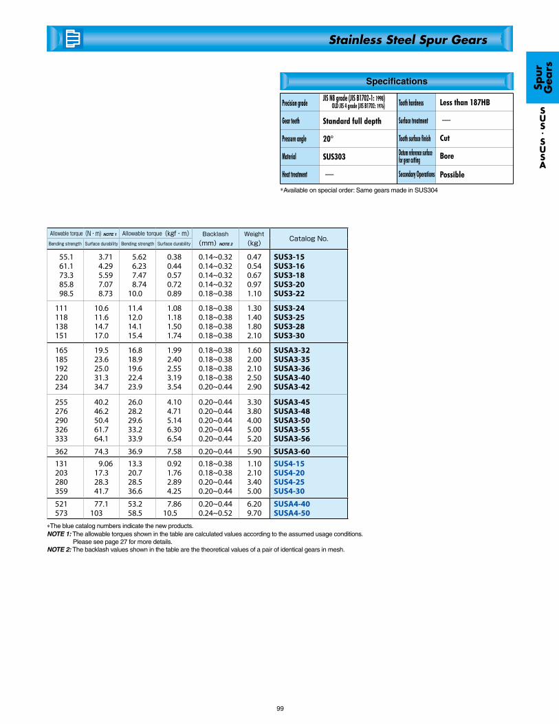
99
*The blue catalog numbers indicate the new products.NOTE 1: The allowable torques shown in the table are calculated values according to the assumed usage conditions.
Please see page 27 for more details. NOTE 2: The backlash values shown in the table are the theoretical values of a pair of identical gears in mesh.
Allowable torque(N・m) NOTE 1 Allowable torque(kgf・m) Backlash(mm) NOTE 2
Weight(kg)
Catalog No.Bending strength Surface durability Bending strength Surface durability
55.161.173.385.898.5
3.714.295.597.078.73
5.626.237.478.74
10.0
0.380.440.570.720.89
0.14~0.320.14~0.320.14~0.320.14~0.320.18~0.38
0.470.540.670.971.10
SUS3-15SUS3-16SUS3-18SUS3-20SUS3-22
111118138151
10.611.614.717.0
11.412.014.115.4
1.081.181.501.74
0.18~0.380.18~0.380.18~0.380.18~0.38
1.301.401.802.10
SUS3-24SUS3-25SUS3-28SUS3-30
165185192220234
19.523.625.031.334.7
16.818.919.622.423.9
1.992.402.553.193.54
0.18~0.380.18~0.380.18~0.380.18~0.380.20~0.44
1.602.002.102.502.90
SUSA3-32SUSA3-35SUSA3-36SUSA3-40SUSA3-42
255276290326333
40.246.250.461.764.1
26.028.229.633.233.9
4.104.715.146.306.54
0.20~0.440.20~0.440.20~0.440.20~0.440.20~0.44
3.303.804.005.005.20
SUSA3-45SUSA3-48SUSA3-50SUSA3-55SUSA3-56
362 74.3 36.9 7.58 0.20~0.44 5.90 SUSA3-60
131203280359
9.0617.328.341.7
13.320.728.536.6
0.921.762.894.25
0.18~0.380.18~0.380.20~0.440.20~0.44
1.102.103.405.00
SUS4-15SUS4-20SUS4-25SUS4-30
521573
77.1103
53.258.5
7.8610.5
0.20~0.440.24~0.52
6.209.70
SUSA4-40SUSA4-50
Spur
G
ears
SUS.SUSA
Stainless Steel Spur Gears
*Available on special order: Same gears made in SUS304
Specifications
Precision grade
Gear teeth
Pressure angle
Material
Heat treatment
Standard full depth
20°
SUS303
-
Tooth hardness
Surface treatment
Tooth surface finish
Secondary Operations
Less than 187HB
-
Cut
Bore
JIS N8 grade (JIS B1702-1: 1998) OLD JIS 4 grade (JIS B1702: 1976)
Datum reference surface for gear cutting
Possible
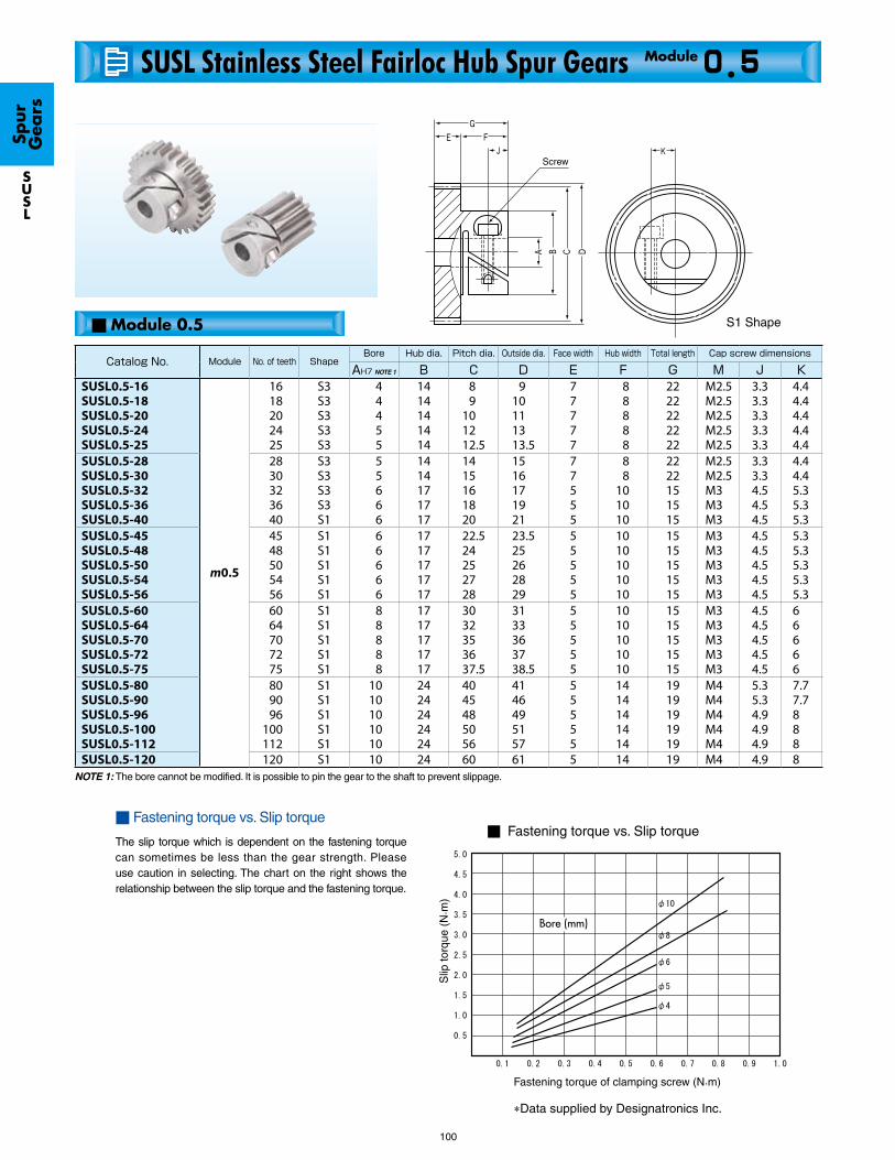
■ Module 0.5
100
■ Fastening torque vs. Slip torque
The slip torque which is dependent on the fastening torque can sometimes be less than the gear strength. Please use caution in selecting. The chart on the right shows the relationship between the slip torque and the fastening torque.
Fastening torque of clamping screw (N.m)
Bore (mm)
Fastening torque vs. Slip torque
Slip
torq
ue (
N. m
)
Screw
NOTE 1: The bore cannot be modified. It is possible to pin the gear to the shaft to prevent slippage.
S1 Shape
*Data supplied by Designatronics Inc.
Catalog No. Module No. of teeth ShapeBore Hub dia. Pitch dia. Outside dia. Face width Hub width Total length Cap screw dimensions
AH7 NOTE 1 B C D E F G M J KSUSL0.5-16SUSL0.5-18SUSL0.5-20SUSL0.5-24SUSL0.5-25
m0.5
1618202425
S3S3S3S3S3
44455
1414141414
89
101212.5
910111313.5
77777
88888
2222222222
M2.5M2.5M2.5M2.5M2.5
3.33.33.33.33.3
4.44.44.44.44.4
SUSL0.5-28SUSL0.5-30SUSL0.5-32SUSL0.5-36SUSL0.5-40
2830323640
S3S3S3S3S1
55666
1414171717
1415161820
1516171921
77555
88
101010
2222151515
M2.5M2.5M3M3M3
3.33.34.54.54.5
4.44.45.35.35.3
SUSL0.5-45SUSL0.5-48SUSL0.5-50SUSL0.5-54SUSL0.5-56
4548 505456
S1S1S1S1S1
66666
1717171717
22.524252728
23.525262829
55555
1010101010
1515151515
M3M3M3M3M3
4.54.54.54.54.5
5.35.35.35.35.3
SUSL0.5-60SUSL0.5-64SUSL0.5-70SUSL0.5-72SUSL0.5-75
6064707275
S1S1S1S1S1
88888
1717171717
3032353637.5
3133363738.5
55555
1010101010
1515151515
M3M3M3M3M3
4.54.54.54.54.5
66666
SUSL0.5-80SUSL0.5-90SUSL0.5-96SUSL0.5-100SUSL0.5-112
809096
100112
S1S1S1S1S1
1010101010
2424242424
4045485056
4146495157
55555
1414141414
1919191919
M4M4M4M4M4
5.35.34.94.94.9
7.77.7888
SUSL0.5-120 120 S1 10 24 60 61 5 14 19 M4 4.9 8
SUSL Stainless Steel Fairloc Hub Spur Gears 0.5Module
Spur
G
ears
SUSL
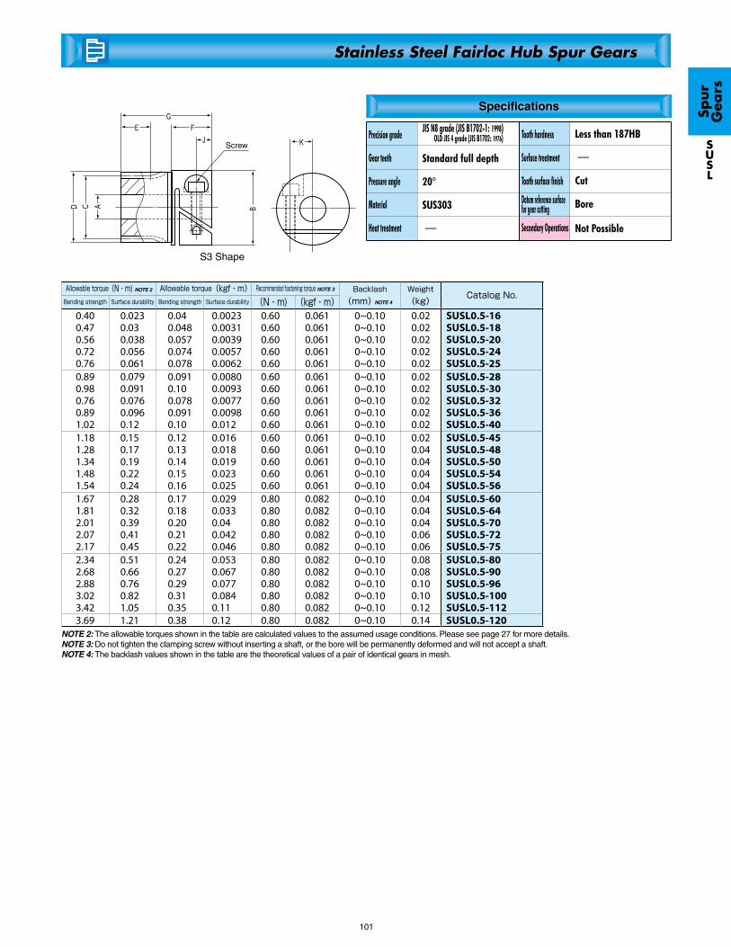
101
NOTE 2: The allowable torques shown in the table are calculated values to the assumed usage conditions. Please see page 27 for more details. NOTE 3: Do not tighten the clamping screw without inserting a shaft, or the bore will be permanently deformed and will not accept a shaft.NOTE 4: The backlash values shown in the table are the theoretical values of a pair of identical gears in mesh.
Screw
S3 Shape
Allowable torque(N・m) NOTE 2 Allowable torque(kgf・m) Recommended fastening torque NOTE 3 Backlash(mm) NOTE 4
Weight(kg)
Catalog No.Bending strength Surface durability Bending strength Surface durability (N・m) (kgf・m)
0.400.470.560.720.76
0.0230.030.0380.0560.061
0.040.0480.0570.0740.078
0.00230.00310.00390.00570.0062
0.600.600.600.600.60
0.0610.0610.0610.0610.061
0~0.100~0.100~0.100~0.100~0.10
0.020.020.020.020.02
SUSL0.5-16SUSL0.5-18SUSL0.5-20SUSL0.5-24SUSL0.5-25
0.890.980.760.891.02
0.0790.0910.0760.0960.12
0.0910.100.0780.0910.10
0.00800.00930.00770.00980.012
0.600.600.600.600.60
0.0610.0610.0610.0610.061
0~0.100~0.100~0.100~0.100~0.10
0.020.020.020.020.02
SUSL0.5-28SUSL0.5-30SUSL0.5-32SUSL0.5-36SUSL0.5-40
1.181.281.341.481.54
0.150.170.190.220.24
0.120.130.140.150.16
0.0160.0180.0190.0230.025
0.600.600.600.600.60
0.0610.0610.0610.0610.061
0~0.100~0.100~0.100~0.100~0.10
0.020.040.040.040.04
SUSL0.5-45SUSL0.5-48SUSL0.5-50SUSL0.5-54SUSL0.5-56
1.671.812.012.072.17
0.280.320.390.410.45
0.170.180.200.210.22
0.0290.0330.040.0420.046
0.800.800.800.800.80
0.0820.0820.0820.0820.082
0~0.100~0.100~0.100~0.100~0.10
0.040.040.040.060.06
SUSL0.5-60SUSL0.5-64SUSL0.5-70SUSL0.5-72SUSL0.5-75
2.342.682.883.023.42
0.510.660.760.821.05
0.240.270.290.310.35
0.0530.0670.0770.0840.11
0.800.800.800.800.80
0.0820.0820.0820.0820.082
0~0.100~0.100~0.100~0.100~0.10
0.080.080.100.100.12
SUSL0.5-80SUSL0.5-90SUSL0.5-96SUSL0.5-100SUSL0.5-112
3.69 1.21 0.38 0.12 0.80 0.082 0~0.10 0.14 SUSL0.5-120
Spur
G
ears
SUSL
Stainless Steel Fairloc Hub Spur Gears
Specifications
Precision grade
Gear teeth
Pressure angle
Material
Heat treatment
Standard full depth
20°
SUS303
-
Tooth hardness
Surface treatment
Tooth surface finish
Secondary Operations
Less than 187HB
-
Cut
Bore
JIS N8 grade (JIS B1702-1: 1998) OLD JIS 4 grade (JIS B1702: 1976)
Datum reference surface for gear cutting
Not Possible
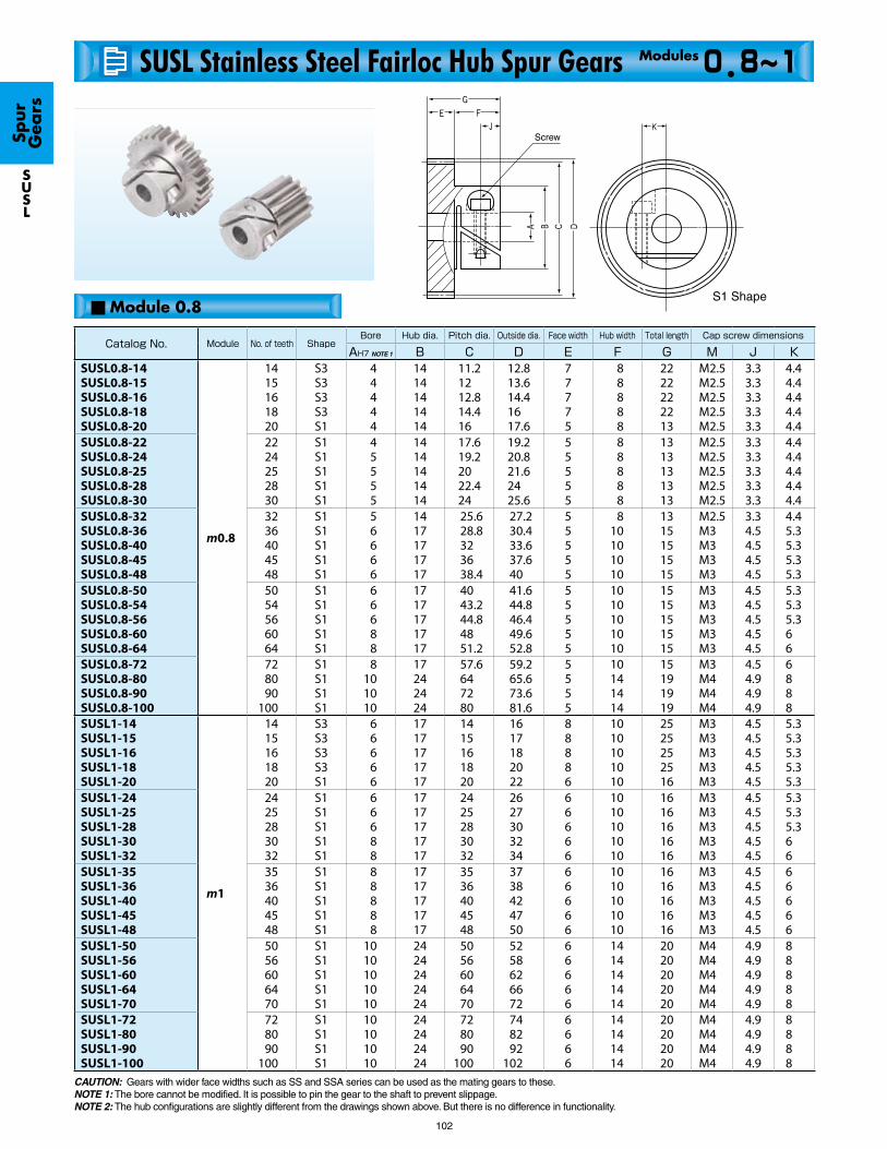
■ Module 0.8
102
CAUTION: Gears with wider face widths such as SS and SSA series can be used as the mating gears to these.NOTE 1: The bore cannot be modified. It is possible to pin the gear to the shaft to prevent slippage.NOTE 2: The hub configurations are slightly different from the drawings shown above. But there is no difference in functionality.
Screw
S1 Shape
Catalog No. Module No. of teeth ShapeBore Hub dia. Pitch dia. Outside dia. Face width Hub width Total length Cap screw dimensions
AH7 NOTE 1 B C D E F G M J KSUSL0.8-14SUSL0.8-15SUSL0.8-16SUSL0.8-18SUSL0.8-20
m0.8
1415161820
S3S3S3S3S1
44444
1414141414
11.21212.814.416
12.813.614.41617.6
77775
88888
2222222213
M2.5M2.5M2.5M2.5M2.5
3.33.33.33.33.3
4.44.44.44.44.4
SUSL0.8-22SUSL0.8-24SUSL0.8-25SUSL0.8-28SUSL0.8-30
2224252830
S1S1S1S1S1
45555
1414141414
17.619.22022.424
19.220.821.62425.6
55555
88888
1313131313
M2.5M2.5M2.5M2.5M2.5
3.33.33.33.33.3
4.44.44.44.44.4
SUSL0.8-32SUSL0.8-36SUSL0.8-40SUSL0.8-45SUSL0.8-48
3236404548
S1S1S1S1S1
56666
1417171717
25.628.8323638.4
27.230.433.637.640
55555
810101010
1315151515
M2.5M3M3M3M3
3.34.54.54.54.5
4.45.35.35.35.3
SUSL0.8-50SUSL0.8-54SUSL0.8-56SUSL0.8-60SUSL0.8-64
5054566064
S1S1S1S1S1
66688
1717171717
4043.244.84851.2
41.644.846.449.652.8
55555
1010101010
1515151515
M3M3M3M3M3
4.54.54.54.54.5
5.35.35.366
SUSL0.8-72SUSL0.8-80SUSL0.8-90SUSL0.8-100
728090
100
S1S1S1S1
8101010
17242424
57.6647280
59.265.673.681.6
5555
10141414
15191919
M3M4M4M4
4.54.94.94.9
6888
SUSL1-14SUSL1-15SUSL1-16SUSL1-18SUSL1-20
m1
1415161820
S3S3S3S3S1
66666
1717171717
1415161820
1617182022
88886
1010101010
2525252516
M3M3M3M3M3
4.54.54.54.54.5
5.35.35.35.35.3
SUSL1-24SUSL1-25SUSL1-28SUSL1-30SUSL1-32
2425283032
S1S1S1S1S1
66688
1717171717
2425283032
2627303234
66666
1010101010
1616161616
M3M3M3M3M3
4.54.54.54.54.5
5.35.35.366
SUSL1-35SUSL1-36SUSL1-40SUSL1-45SUSL1-48
3536404548
S1S1S1S1S1
88888
1717171717
3536404548
3738424750
66666
1010101010
1616161616
M3M3M3M3M3
4.54.54.54.54.5
66666
SUSL1-50SUSL1-56SUSL1-60SUSL1-64SUSL1-70
5056606470
S1S1S1S1S1
1010101010
2424242424
5056606470
5258626672
66666
1414141414
2020202020
M4M4M4M4M4
4.94.94.94.94.9
88888
SUSL1-72SUSL1-80SUSL1-90SUSL1-100
728090
100
S1S1S1S1
10101010
24242424
728090
100
748292
102
6666
14141414
20202020
M4M4M4M4
4.94.94.94.9
8888
0.8~1Modules
Spur
G
ears
SUSL
SUSL Stainless Steel Fairloc Hub Spur Gears

103
NOTE 3: The allowable torques shown in the table are calculated values to the assumed usage conditions. Please see page 27 for more details. NOTE 4: Do not tighten the clamping screw without inserting a shaft, or the bore will be permanently deformed and will not accept a shaft.NOTE 5: The backlash values shown in the table are the theoretical values of a pair of identical gears in mesh.
Screw
S3 Shape
Allowable torque(N・m) NOTE 2 Allowable torque(kgf・m) Recommended fastening torque Backlash(mm) NOTE 4
Weight(kg)
Catalog No.Bending strength Surface durability Bending strength Surface durability (N・m) (kgf・m)
0.820.921.011.221.02
0.0480.0560.0650.0830.076
0.0830.0930.100.120.10
0.00490.00570.00660.00850.0077
0.600.600.600.600.60
0.0610.0610.0610.0610.061
0~0.100~0.100~0.100~0.100~0.10
0.020.020.020.020.02
SUSL0.8-14SUSL0.8-15SUSL0.8-16SUSL0.8-18SUSL0.8-20
1.171.321.401.631.79
0.0910.110.120.150.17
0.120.130.140.170.18
0.00930.0110.0120.0150.018
0.600.600.600.600.60
0.0610.0610.0610.0610.061
0~0.100~0.100~0.100~0.100~0.10
0.020.020.020.020.02
SUSL0.8-22SUSL0.8-24SUSL0.8-25SUSL0.8-28SUSL0.8-30
1.952.282.613.023.27
0.200.260.320.410.47
0.200.230.270.310.33
0.0200.0260.0330.0420.048
0.600.600.600.600.60
0.0610.0610.0610.0610.061
0~0.100~0.100~0.100~0.100~0.10
0.020.040.040.060.06
SUSL0.8-32SUSL0.8-36SUSL0.8-40SUSL0.8-45SUSL0.8-48
3.443.783.954.284.63
0.510.610.650.760.87
0.350.390.400.440.47
0.0530.0620.0670.0770.088
0.600.600.600.800.80
0.0610.0610.0610.0820.082
0~0.100~0.100~0.100~0.100~0.10
0.060.060.080.080.08
SUSL0.8-50SUSL0.8-54SUSL0.8-56SUSL0.8-60SUSL0.8-64
5.316.006.867.72
1.111.381.772.21
0.540.610.700.79
0.110.140.180.23
0.800.800.800.80
0.0820.0820.0820.082
0~0.100~0.100~0.100~0.10
0.100.160.200.22
SUSL0.8-72SUSL0.8-80SUSL0.8-90SUSL0.8-100
1.461.631.812.171.91
0.0880.100.120.150.14
0.150.170.180.220.19
0.00900.0100.0120.0160.015
0.600.600.600.600.60
0.0610.0610.0610.0610.061
0~0.100~0.100~0.100~0.100~0.10
0.040.040.040.040.02
SUSL1-14SUSL1-15SUSL1-16SUSL1-18SUSL1-20
2.482.623.063.363.66
0.210.230.290.340.39
0.250.270.310.340.37
0.0210.0230.0300.0340.039
0.600.600.600.800.80
0.0610.0610.0610.0820.082
0~0.100~0.100~0.100~0.100~0.10
0.040.040.040.040.04
SUSL1-24SUSL1-25SUSL1-28SUSL1-30SUSL1-32
4.124.274.895.676.14
0.470.490.620.790.91
0.420.440.500.580.63
0.0480.0500.0630.0810.093
0.800.800.800.800.80
0.0820.0820.0820.0820.082
0~0.100~0.100~0.100~0.100~0.10
0.060.060.060.080.10
SUSL1-35SUSL1-36SUSL1-40SUSL1-45SUSL1-48
6.457.408.038.679.63
0.991.251.451.662.00
0.660.750.820.880.98
0.100.130.150.170.20
0.800.800.800.800.80
0.0820.0820.0820.0820.082
0~0.100~0.100~0.100~0.100~0.10
0.120.140.160.180.20
SUSL1-50SUSL1-56SUSL1-60SUSL1-64SUSL1-70
9.9511.212.914.5
2.122.653.404.25
1.021.151.311.48
0.220.270.350.43
0.800.800.800.80
0.0820.0820.0820.082
0~0.100~0.100~0.100~0.10
0.220.260.320.38
SUSL1-72SUSL1-80SUSL1-90SUSL1-100
Spur
G
ears
SUSL
Stainless Steel Fairloc Hub Spur Gears
Specifications
Precision grade
Gear teeth
Pressure angle
Material
Heat treatment
Standard full depth
20°
SUS303
-
Tooth hardness
Surface treatment
Tooth surface finish
Secondary Operations
Less than 187HB
-
Cut
Bore
JIS N8 grade (JIS B1702-1: 1998) OLD JIS 4 grade (JIS B1702: 1976)
Datum reference surface for gear cutting
Not Possible
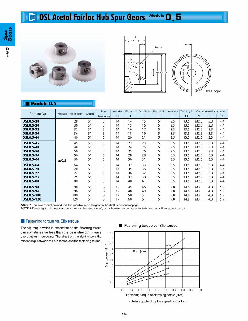
104
■ Module 0.5
NOTE 1: The bore cannot be modified. It is possible to pin the gear to the shaft to prevent slippage.NOTE 2: Do not tighten the clamping screw without inserting a shaft, or the bore will be permanently deformed and will not accept a shaft.
Fastening torque of clamping screw (N.m)
Bore (mm)
Fastening torque vs. Slip torque
Slip
torq
ue (
N. m
)
*Data supplied by Designatronics Inc.
■ Fastening torque vs. Slip torque
The slip torque which is dependent on the fastening torque can sometimes be less than the gear strength. Please use caution in selecting. The chart on the right shows the relationship between the slip torque and the fastening torque.
Screw
S1 Shape
Catalog No. Module No. of teeth ShapeBore Hub dia. Pitch dia. Outside dia. Face width Hub width Total length Cap screw dimensions
AH7 NOTE 1 B C D E F G M J KDSL0.5-28DSL0.5-30DSL0.5-32DSL0.5-36DSL0.5-40
m0.5
2830323640
S1S1S1S1S1
55555
1414141414
1415161820
1516171921
55555
8.58.58.58.58.5
13.513.513.513.513.5
M2.5M2.5M2.5M2.5M2.5
3.33.33.33.33.3
4.44.44.44.44.4
DSL0.5-45DSL0.5-48DSL0.5-50DSL0.5-56DSL0.5-60
4548505660
S1S1S1S1S1
55555
1414141414
22.524252830
23.525262931
55555
8.58.58.58.58.5
13.513.513.513.513.5
M2.5M2.5M2.5M2.5M2.5
3.33.33.33.33.3
4.44.44.44.44.4
DSL0.5-64DSL0.5-70DSL0.5-72DSL0.5-75DSL0.5-80
6470727580
S1S1S1S1S1
55555
1414141414
32353637.540
33363738.541
55555
8.58.58.58.58.5
13.513.513.513.513.5
M2.5M2.5M2.5M2.5M2.5
3.33.33.33.33.3
4.44.44.44.44.4
DSL0.5-90DSL0.5-96DSL0.5-100DSL0.5-120
9096
100120
S1S1S1S1
8888
17171717
45485060
46495161
5555
9.89.89.89.8
14.814.814.814.8
M3M3M3M3
4.34.34.34.3
5.95.95.95.9
DSL Acetal Fairloc Hub Spur Gears 0.5Module
Spur
G
ears
DSL

105
NOTE 3: The allowable torques shown in the table are calculated values using the Lewis formula. Please see page 27 for more details.
NOTE 4: The backlash values shown in the table are the theoretical values of a pair of identicalgears in mesh.
Allowable torque(N・m) NOTE 3 Allowable torque(kgf・m) Recommended fastening torque Backlash(mm)NOTE 4
Weight(kg)
Catalog No.Bending strength Surface durability Bending strength Surface durability (N・m) (kgf・m)
0.390.430.460.540.62
―――――
0.040.0440.0470.0550.063
―――――
0.600.600.600.600.60
0.0610.0610.0610.0610.061
0~0.100~0.100~0.100~0.100~0.10
1212121212
DSL0.5-28DSL0.5-30DSL0.5-32DSL0.5-36DSL0.5-40
0.710.780.820.931.01
―――――
0.0730.0790.0830.0950.10
―――――
0.600.600.600.600.80
0.0610.0610.0610.0610.082
0~0.100~0.100~0.100~0.100~0.10
1213131414
DSL0.5-45DSL0.5-48DSL0.5-50DSL0.5-56DSL0.5-60
1.081.201.241.291.39
―――――
0.110.120.130.130.14
―――――
0.800.800.800.800.80
0.0820.0820.0820.0820.082
0~0.100~0.100~0.100~0.100~0.10
1516161719
DSL0.5-64DSL0.5-70DSL0.5-72DSL0.5-75DSL0.5-80
1.581.701.782.15
――――
0.160.170.180.22
――――
0.800.800.800.80
0.0820.0820.0820.082
0~0.100~0.100~0.100~0.10
24252532
DSL0.5-90DSL0.5-96DSL0.5-100DSL0.5-120
Spur
G
ears
DSL
Acetal Fairloc Hub Spur Gears
Specifications
Precision grade
Gear teeth
Pressure angle
Material
Heat treatment
Standard full depth
20°
Acetal with SUS303 Insert
-
Tooth hardness
Surface treatment
Tooth surface finish
Secondary Operations
110~120HRR
-
Cut
Bore
JIS N10 grade (JIS B1702-2: 1998)
Datum reference surface for gear cutting
Not Possible

106
■ Module 0.8, 1
CAUTION: Gears with wider face widths such as SS and SSA series can be used as the mating gars to these.NOTE 1: The bore cannot be modified. It is possible to pin the gear to the shaft to prevent slippage.NOTE 2 : Do not tighten the clamping screw without inserting a shaft, or the bore will be permanently deformed and will not accept a shaft.
S1 Shape
Catalog No. Module No. of teeth ShapeBore Hub dia. Pitch dia. Outside dia. Face width Hub width Total length Cap screw dimensions NOTE 2
AH7 NOTE 1 B C D E F G M J KDSL0.8-20DSL0.8-24DSL0.8-25DSL0.8-28DSL0.8-30
m0.8
2830323640
S1S1S1S1S1
55555
1414141414
1415161820
1516171921
55555
8.58.58.58.58.5
13.513.513.513.513.5
M2.5M2.5M2.5M2.5M2.5
3.33.33.33.33.3
4.44.44.44.44.4
DSL0.8-32DSL0.8-36DSL0.8-40DSL0.8-45DSL0.8-48
4548505660
S1S1S1S1S1
55555
1414141414
22.524252830
23.525262931
55555
8.58.58.58.58.5
13.513.513.513.513.5
M2.5M2.5M2.5M2.5M2.5
3.33.33.33.33.3
4.44.44.44.44.4
DSL0.8-50DSL0.8-56DSL0.8-60DSL0.8-72DSL0.8-80
6470727580
S1S1S1S1S1
55555
1414141414
32353637.540
33363738.541
55555
8.58.58.58.58.5
13.513.513.513.513.5
M2.5M2.5M2.5M2.5M2.5
3.33.33.33.33.3
4.44.44.44.44.4
DSL0.8-90DSL0.8-100
90100
S1S1
88
1717
7280
73.681.6
55
9.89.8
14.814.8
M3M3
4.34.3
5.95.9
DSL1-15DSL1-16DSL1-18DSL1-20DSL1-24
m1
1516182024
S1S1S1S1S1
55555
1414141414
1516182024
1718202226
55555
8.58.58.58.58.5
13.513.513.513.513.5
M2.5M2.5M2.5M2.5M2.5
3.33.33.33.33.3
4.44.44.44.44.4
DSL1-25DSL1-28DSL1-30DSL1-32DSL1-35
2528303235
S1S1S1S1S1
55888
1414171717
2528303235
2730323437
55555
8.58.59.89.89.8
13.513.514.814.814.8
M2.5M2.5M3M3M3
3.33.34.34.34.3
4.44.45.95.95.9
DSL1-36DSL1-40DSL1-45DSL1-48DSL1-50
3640454850
S1S1S1S1S1
88888
1717171717
3640454850
3842475052
55555
9.89.89.89.89.8
14.814.814.814.814.8
M3M3M3M3M3
4.34.34.34.34.3
5.95.95.95.95.9
DSL1-56DSL1-60DSL1-64DSL1-70DSL1-72
5660647072
S1S1S1S1S1
88888
1717171717
5660647072
5862667274
55555
9.89.89.89.89.8
14.814.814.814.814.8
M3M3M3M3M3
4.34.34.34.34.3
5.95.95.95.95.9
DSL1-80DSL1-90DSL1-100
8090
100
S1S1S1
888
171717
8090
100
8292
102
555
9.89.89.8
14.814.814.8
M3M3M3
4.34.34.3
5.95.95.9
DSL Acetal Fairloc Hub Spur Gears 0.8~1Modules
Spur
G
ears
DSL

107
NOTE 3: The allowable torques shown in the table are calculated values using the Lewis formula. Please see page 27 for more details. NOTE 4: The backlash values shown in the table are the theoretical values of a pair of identical gears in mesh.
Allowable torque(N・m) NOTE 3 Allowable torque(kgf・m) Recommended fastening torque Backlash(mm)NOTE 4
Weight(kg)
Catalog No.Bending strength Surface durability Bending strength Surface durability (N・m) (kgf・m)
0.580.730.780.890.97
―――――
0.0590.0750.0790.0910.099
―――――
0.600.600.600.600.60
0.0610.0610.0610.0610.061
0~0.100~0.100~0.100~0.100~0.10
1112121213
DSL0.8-20DSL0.8-24DSL0.8-25DSL0.8-28DSL0.8-30
1.061.231.411.621.76
―――――
0.110.130.140.170.18
―――――
0.600.600.600.600.60
0.0610.0610.0610.0610.061
0~0.100~0.100~0.100~0.100~0.10
1415151618
DSL0.8-32DSL0.8-36DSL0.8-40DSL0.8-45DSL0.8-48
1.852.112.282.8
3.15
―――――
0.190.220.230.290.32
―――――
0.600.600.800.800.80
0.0610.0610.0820.0820.082
0~0.100~0.100~0.100~0.100~0.10
1920253035
DSL0.8-50DSL0.8-56DSL0.8-60DSL0.8-72DSL0.8-80
3.584.03
――
0.370.41
――
0.800.80
0.0820.082
0~0.100~0.10
4248
DSL0.8-90DSL0.8-100
0.530.590.690.801.00
―――――
0.0540.060.070.0810.10
―――――
0.600.600.600.600.60
0.0610.0610.0610.0610.061
0~0.100~0.100~0.100~0.100~0.10
1010111112
DSL1-15DSL1-16DSL1-18DSL1-20DSL1-24
1.061.221.331.441.62
―――――
0.110.120.140.150.17
―――――
0.600.600.800.800.80
0.0610.0610.0820.0820.082
0~0.100~0.100~0.100~0.100~0.10
1214171920
DSL1-25DSL1-28DSL1-30DSL1-32DSL1-35
1.681.922.222.412.53
―――――
0.170.200.230.250.26
―――――
0.800.800.800.800.80
0.0820.0820.0820.0820.082
0~0.100~0.100~0.100~0.100~0.10
2022252527
DSL1-36DSL1-40DSL1-45DSL1-48DSL1-50
2.883.123.353.713.83
―――――
0.290.320.340.380.39
―――――
0.800.800.800.800.80
0.0820.0820.0820.0820.082
0~0.100~0.100~0.100~0.100~0.10
3033354041
DSL1-56DSL1-60DSL1-64DSL1-70DSL1-72
4.304.895.49
―――
0.440.500.56
―――
0.800.800.80
0.0820.0820.082
0~0.100~0.100~0.10
485868
DSL1-80DSL1-90DSL1-100
Spur
G
ears
DSL
Acetal Fairloc Hub Spur Gears
Specifications
Precision grade
Gear teeth
Pressure angle
Material
Heat treatment
Standard full depth
20°
Acetal with SUS303 Insert
-
Tooth hardness
Surface treatment
Tooth surface finish
Secondary Operations
110~120HRR
-
Cut
Bore
JIS N10 grade (JIS B1702-2: 1998)
Datum reference surface for gear cutting
Not Possible

108
NOTE 1: Even though the holding strength at the material interface is designed to be stronger than the teeth, any secondary operation may weaken the holding strength. When the core O.D. is the same as the hub diameter, you may see some serration on the hub. There is no effect on the strength of the gear.
■ Definition of holdingstrength and safety factor
1 The holding strength between the metal core and the molded material is a function of the contact area. The relationship between the core outside diameter and the radial strength (torque) is shown on the left, while the relationship between the core diameter and the resistant thrust force is shown on the right.
S1 Shape
■ Module 1
Core O.D.(cm)
Rad
ial s
treng
th (K
gf. m
per
cm
of c
onta
ct s
urfa
ce w
idth
)
■ Relationship between radial strength and core diameter
Core O.D.(cm)
Res
ista
nt th
rust
forc
e (K
gf. m
per
cm
of c
onta
ct s
urfa
ce w
idth
) ■ Relationship between resistant thrust force and core diameter
Catalog No. Module No. of teeth ShapeBore Hub dia. Pitch dia. Outside dia. Face width Hub width Total length Metal core dia. NOTE 3
AH7 B C D E F G HNSU1-30NSU1-32NSU1-34NSU1-35NSU1-36
m1
3032343536
S1S1S1S1S1
88888
2022252525
3032343536
3234363738
1010101010
1010101010
2020202020
2022252525
NSU1-40NSU1-45NSU1-48NSU1-50NSU1-60
4045485060
S1S1S1S1S1
1010101010
2530303040
4045485060
4247505262
1010101010
1010101010
2020202020
2834343445
NSU1-70NSU1-80NSU1-90NSU1-100
708090
100
S1S1S1S1
10101010
40404040
708090
100
728292
102
10101010
10101010
20202020
45455565
NSU Plastic Spur Gears with Steel Core 1Module
Spur
G
ears
NSU

Plastic Spur Gears with Steel Core
109
NOTE 2: The allowable torques shown in the table are calculated values using the Lewis formula.Please see page 27 for more details.
NOTE 3: The backlash values shown in the table are the theoretical values of a pair of identical gears in mesh.
* Data supplied by Japan Polypenco Limited.
2 When the ambient temperature rises, obtain the temperature compensation factor, T, from the chart on the right. Also, use a safety factor of 4 or 5 in the calculation.
1Safety factor
Tal = Tmax x x T
■ Ambient temperature compensation factor T
Temperature(°C)
where Tal = Allowable holding strength at the contact surface Tmax = Radial strength - Find from the charts on the left T = Temperature compensation factor from the chart on the right
Allowable torque(N・m) Allowable torque(kgf・m) Backlash(mm)NOTE 3
Weight(kg)
Catalog No.Bending strength Bending strength
1.421.541.661.731.79
0.140.160.170.180.18
0.12~0.260.12~0.260.12~0.260.12~0.260.12~0.26
0.050.060.080.080.08
NSU1-30NSU1-32NSU1-34NSU1-35NSU1-36
2.052.372.562.703.33
0.210.240.260.280.34
0.12~0.260.12~0.260.12~0.260.12~0.260.14~0.28
0.080.120.130.130.23
NSU1-40NSU1-45NSU1-48NSU1-50NSU1-60
3.964.605.245.89
0.400.470.530.60
0.14~0.280.14~0.280.14~0.280.14~0.28
0.240.250.320.40
NSU1-70NSU1-80NSU1-90NSU1-100
Spur
G
ears
NSU
Specifications
Precision grade
Gear teeth
Pressure angle
Material
Heat treatment
Standard full depth
20°
MC601ST with S45C core
-
Tooth hardness
Surface treatment
Tooth surface finish
Secondary Operations
115~120HRR
-
Cut
Bore
JIS N9 grade (JIS B1702-1: 1998) OLD JIS 5 grade (JIS B1702: 1976)
Datum reference surface for gear cutting
Possible

110
NOTE 1: Even though the holding strength at the material interface is designed to be stronger than the teeth, a secondary operation may weaken the holding strength. When the core O.D. is the same as the hub diameter, you may see some serration on the hub. There is no effect on the strength of the gear.
MC601ST
S45CS1 Shape
■ Module 1.5, 2
Catalog No. Module No. of teeth ShapeBore Hub dia. Pitch dia. Outside dia. Face width Hub width Total length Metal core dia. NOTE 1
AH7 B C D E F G HNSU1.5-28NSU1.5-30NSU1.5-32NSU1.5-34NSU1.5-35
m1.5
2830323435
S1S1S1S1S1
1010101010
3030333333
4245485152.5
4548515455.5
1515151515
1212121212
2727272727
3030333336
NSU1.5-36NSU1.5-40NSU1.5-45NSU1.5-48NSU1.5-50
3640454850
S1S1S1S1S1
1010101012
3340404040
546067.57275
576370.57578
1515151515
1212121212
2727272727
3645454545
NSU1.5-56NSU1.5-60NSU1.5-68NSU1.5-70NSU1.5-80
5660687080
S1S1S1S1S1
1212121212
5050505060
8490
102105120
8793
105108123
1515151515
1212121212
2727272727
5555677085
NSU1.5-90 90 S1 12 60 135 138 15 12 27 100
NSU2-20NSU2-22NSU2-24NSU2-25NSU2-28
m2
2022242528
S1S1S1S1S1
1010101010
2230303035
4044485056
4448525460
2020202020
1414141414
3434343434
2230303035
NSU2-30NSU2-32NSU2-34NSU2-35NSU2-36
3032343536
S1S1S1S1S1
1012121212
3540404040
6064687072
6468727476
2020202020
1414141414
3434343434
3540454545
NSU2-40NSU2-44NSU2-45NSU2-48NSU2-50
4044454850
S1S1S1S1S1
1515151515
5555556060
80889096
100
849294
100104
2020202020
1414141414
3434343434
6060606565
NSU2-56NSU2-60NSU2-68NSU2-70NSU2-80
5660687080
S1S1S1S1S1
1515151515
6060606060
112120136140160
116124140144164
2020202020
1414141414
3434343434
6585
100105125
NSU Plastic Spur Gears with Steel Core 1.5~2Modules
Spur
G
ears
NSU

Plastic Spur Gears with Steel Core
111
NOTE 2: The allowable torques shown in the table are calculated values using the Lewis formula.Please see page 27 for more details.
NOTE 3: The backlash values shown in the table are the theoretical values of a pair of identical gears in mesh.
Allowable torque(N・m) NOTE 2 Allowable torque(kgf・m) Backlash(mm)NOTE 3
Weight(kg)
Catalog No.Bending strength Bending strength
4.394.785.195.615.83
0.450.490.530.570.59
0.14~0.300.14~0.300.14~0.300.16~0.320.16~0.32
0.150.150.180.190.21
NSU1.5-28NSU1.5-30NSU1.5-32NSU1.5-34NSU1.5-35
6.056.97.988.669.11
0.620.700.810.880.93
0.16~0.320.16~0.320.16~0.320.16~0.320.16~0.32
0.210.310.330.340.34
NSU1.5-36NSU1.5-40NSU1.5-45NSU1.5-48NSU1.5-50
10.411.212.913.415.5
1.061.151.321.361.58
0.16~0.320.16~0.320.18~0.360.18~0.360.18~0.36
0.500.520.660.691.00
NSU1.5-56NSU1.5-60NSU1.5-68NSU1.5-70NSU1.5-80
17.7 1.80 0.18~0.36 1.28 NSU1.5-90
6.777.668.559.03
10.4
0.690.780.870.921.06
0.18~0.340.18~0.340.18~0.340.18~0.340.20~0.36
0.100.190.200.200.27
NSU2-20NSU2-22NSU2-24NSU2-25NSU2-28
11.312.313.313.814.3
1.151.251.361.411.46
0.20~0.360.20~0.360.20~0.360.20~0.360.20~0.36
0.280.360.410.410.42
NSU2-30NSU2-32NSU2-34NSU2-35NSU2-36
16.418.418.920.521.6
1.671.881.932.092.20
0.20~0.360.20~0.360.20~0.360.20~0.360.20~0.36
0.710.730.750.880.90
NSU2-40NSU2-44NSU2-45NSU2-48NSU2-50
24.626.630.731.736.8
2.512.723.133.233.76
0.22~0.380.22~0.380.22~0.380.22~0.380.22~0.38
0.941.301.651.782.37
NSU2-56NSU2-60NSU2-68NSU2-70NSU2-80
Spur
G
ears
NSU
Specifications
Precision grade
Gear teeth
Pressure angle
Material
Heat treatment
Standard full depth
20°
MC601ST with S45C core
-
Tooth hardness
Surface treatment
Tooth surface finish
Secondary Operations
115~120HRR
-
Cut
Bore
JIS N9 grade (JIS B1702-1: 1998) OLD JIS 5 grade (JIS B1702: 1976)
Datum reference surface for gear cutting
Possible

112
NOTE 1: Even though the holding strength at the material interface is designed to be stronger than the teeth, a secondary operation may weaken the holding strength. When the core O.D. is the same as the hub diameter, you may see some serration on the hub. There is no effect on the strength of the gear.
MC601ST
S45CS1 Shape
■ Module 2.5, 3
Catalog No. Module No. of teeth ShapeBore Hub dia. Pitch dia. Outside dia. Face width Hub width Total length Metal core dia. NOTE 1
AH7 B C D E F G HNSU2.5-18NSU2.5-20NSU2.5-22NSU2.5-24NSU2.5-25
m2.5
1820222425
S1S1S1S1S1
1212121212
2528353535
4550556062.5
5055606567.5
2525252525
1515151515
4040404040
2528353535
NSU2.5-28NSU2.5-30NSU2.5-32NSU2.5-34NSU2.5-35
2830323435
S1S1S1S1S1
1212121212
4045455055
7075808587.5
7580859092.5
2525252525
1515151515
4040404040
4050505560
NSU2.5-36NSU2.5-40NSU2.5-44NSU2.5-45NSU2.5-48
3640444548
S1S1S1S1S1
1215151515
5565656565
90100110112.5120
95105115117.5125
2525252525
1515151515
4040404040
6070757585
NSU2.5-50NSU2.5-56NSU2.5-60NSU2.5-68NSU2.5-70
5056606870
S1S1S1S1S1
1515202020
6565707070
125140150170175
1301451 55175180
2525252525
1515151515
4040404040
95105115135140
NSU3-16NSU3-18NSU3-20NSU3-22NSU3-24
m3
1618202224
S1S1S1S1S1
1212121212
2430333843
4854606672
5460667278
3030303030
1717171717
4747474747
2430333843
NSU3-25NSU3-28NSU3-30NSU3-32NSU3-34
2528303234
S1S1S1S1S1
1215151515
4550556060
75849096
102
819096
102108
3030303030
1717171717
4747474747
4550606565
NSU3-35NSU3-36NSU3-40NSU3-44NSU3-45
3536404445
S1S1S1S1S1
1515202020
6060707070
105108120132135
111114126138141
3030303030
1717171717
4747474747
75808595
105
NSU3-48NSU3-50NSU3-56NSU3-60NSU3-68
4850566068
S1S1S1S1S1
2020202020
7070707070
144150168180204
150156174186210
3030303030
1717171717
4747474747
105105130145165
NSU3-70 70 S1 20 70 210 216 30 17 47 175
NSU Plastic Spur Gears with Steel Core 2.5~3Modules
Spur
G
ears
NSU

Plastic Spur Gears with Steel Core
113
NOTE 2: The allowable torques shown in the table are calculated values using the Lewis formula. Please see page 27 for more details.NOTE 3: The backlash values shown in the table are the theoretical values of a pair of identical gears in mesh.
Allowable torque(N・m) NOTE 2 Allowable torque(kgf・m) Backlash(mm)NOTE 3
Weight(kg)
Catalog No.Bending strength Bending strength
11.413.215.016.717.6
1.171.351.531.701.80
0.20~0.360.20~0.360.22~0.380.22~0.380.22~0.38
0.150.200.310.330.33
NSU2.5-18NSU2.5-20NSU2.5-22NSU2.5-24NSU2.5-25
20.322.124.026.027.0
2.072.252.452.652.75
0.22~0.380.22~0.380.22~0.380.22~0.380.22~0.38
0.440.620.630.760.90
NSU2.5-28NSU2.5-30NSU2.5-32NSU2.5-34NSU2.5-35
28.032.035.937.040.1
2.853.263.673.774.09
0.22~0.380.22~0.380.24~0.400.24~0.400.24~0.40
0.911.201.351.401.60
NSU2.5-36NSU2.5-40NSU2.5-44NSU2.5-45NSU2.5-48
42.248.052.059.961.9
4.304.905.306.116.32
0.24~0.400.24~0.400.24~0.400.24~0.400.24~0.40
1.902.232.603.413.63
NSU2.5-50NSU2.5-56NSU2.5-60NSU2.5-68NSU2.5-70
16.919.722.925.828.8
1.722.012.332.642.94
0.28~0.440.30~0.460.30~0.460.30~0.460.30~0.46
0.170.280.350.460.59
NSU3-16NSU3-18NSU3-20NSU3-22NSU3-24
30.535.138.241.544.9
3.113.583.904.234.58
0.30~0.460.30~0.460.30~0.460.30~0.460.32~0.48
0.650.781.101.201.30
NSU3-25NSU3-28NSU3-30NSU3-32NSU3-34
46.648.455.262.163.9
4.754.935.636.336.51
0.32~0.480.32~0.480.32~0.480.32~0.480.32~0.48
1.501.701.902.302.70
NSU3-35NSU3-36NSU3-40NSU3-44NSU3-45
69.272.983.089.9
104
7.067.438.469.17
10.6
0.32~0.480.32~0.480.32~0.480.32~0.480.32~0.48
2.702.803.804.605.80
NSU3-48NSU3-50NSU3-56NSU3-60NSU3-68
107 10.9 0.32~0.48 6.40 NSU3-70
Spur
G
ears
NSU
Specifications
Precision grade
Gear teeth
Pressure angle
Material
Heat treatment
Standard full depth
20°
MC601ST with S45C core
-
Tooth hardness
Surface treatment
Tooth surface finish
Secondary Operations
115~120HRR
-
Cut
Bore
JIS N9 grade (JIS B1702-1: 1998) OLD JIS 5 grade (JIS B1702: 1976)
Datum reference surface for gear cutting
Possible

PU
114
NOTE 1: Even though the holding strength at the material interface is designed to be stronger than the teeth, a secondary operation may weaken the holding strength. When the core O.D. is the same as the hub diameter, you may see some serration on the hub. There is no effect on the strength of the gear.
MC901
SUS303 S1 Shape
■ Module 1, 1.5, 2
Catalog No. Module No. of teeth ShapeBore Hub dia. Pitch dia. Outside dia. Face width Hub width Total length Metal core dia. NOTE 1
AH7 B C D E F G H
PU1-30PU1-35PU1-40PU1-50PU1-60PU1-80
m1
303540506080
S1S1S1S1S1S1
88
10101010
202525304040
303540506080
323742526282
101010101010
101010101010
202020202020
202528344545
PU1.5-30PU1.5-35PU1.5-40PU1.5-50PU1.5-60PU1.5-80
m1.5
303540506080
S1S1S1S1S1S1
101010121212
303340405060
4552.5607590
120
4855.5637893
123
151515151515
121212121212
272727272727
303645455585
PU2-20PU2-25PU2-30PU2-35PU2-40PU2-50PU2-60
m2
20253035405060
S1S1S1S1S1S1S1
10101012151515
22303540556060
4050607080
100120
4454647484
104124
20202020202020
14141414141414
34343434343434
22303545606585
PU Plastic Spur Gears with Stainless Steel Core 1~2Modules
Spur
G
ears

Plastic Spur Gears with Stainless Steel Core
PU
115
NOTE 2: The allowable torques shown in the table are calculated values using the Lewis formula.Please see page 27 for more details.
NOTE 3: The backlash values shown in the table are the theoretical values of a pair of identical gears in mesh.
Allowable torque(N・m) NOTE 2 Allowable torque(kgf・m) Backlash(mm)NOTE 3
Weight(kg)
Catalog No.Bending strength Bending strength
1.031.251.481.962.413.34
0.100.130.150.200.250.34
0.12~0.260.12~0.260.12~0.260.12~0.260.14~0.280.14~0.28
0.050.080.080.130.230.25
PU1-30PU1-35PU1-40PU1-50PU1-60PU1-80
3.464.225.006.608.14
11.26
0.350.430.510.670.831.15
0.14~0.300.16~0.320.16~0.320.16~0.320.16~0.320.18~0.36
0.150.210.310.340.521.00
PU1.5-30PU1.5-35PU1.5-40PU1.5-50PU1.5-60PU1.5-80
4.916.548.20
10.011.915.719.3
0.500.670.841.021.211.601.97
0.18~0.340.18~0.340.20~0.360.20~0.360.20~0.360.20~0.360.22~0.38
0.100.200.280.410.710.901.30
PU2-20PU2-25PU2-30PU2-35PU2-40PU2-50PU2-60
Spur
G
ears
Specifications
Precision grade
Gear teeth
Pressure angle
Material
Heat treatment
Standard full depth
20°
MC901 with SUS303 core
-
Tooth hardness
Surface treatment
Tooth surface finish
Secondary Operations
115~120HRR
-
Cut
Bore
JIS N9 grade (JIS B1702-1: 1998) OLD JIS 5 grade (JIS B1702: 1976)
Datum reference surface for gear cutting
Possible

PS
116
A key, taper pin, roll or spiral pin, set screw or pressed bushing can be used to fasten a plastic gear to a shaft. For conditions shown below, there is a tendency for the gear to loosen. Therefore, a metal hub must be used to fix the gear:
1. When the ambient temperature is high. 2. When the gear diameter is large. 3. When the gear is subjected to reversing load
which causes high impact on the key.
The diagrams on the right are three examples of methods for fastening plastic gears to metal hubs. If the shape of a gear is not suitable for bolt fastening, then the overmolding of plastic on a metal hub is recommended (shown in the far right diagram).
USEFUL HINT
S1 Shape
■ Module 1
MC nylon MC nylon MC nylon
Metal Metal Metal
Metal
The overmolding of plastic on a metal hub
MC nylon
NOTE 1: The bore tolerance at the time of production is H8. Significant variations in temperature or humidity can cause dimensional changes plastic gears (MC Nylon). Please see page 32 for more details.
Catalog No. Module No. of teeth ShapeBore NOTE 1 Hub dia. Pitch dia. Outside dia. Face width Hub width Total length
AH7 B C D E F GPS1-15PS1-16PS1-18PS1-20PS1-22
m1
1516182022
S1S1S1S1S1
66668
1212141618
1516182022
1718202224
1010101010
1010101010
2020202020
PS1-24PS1-25PS1-26PS1-28PS1-30
2425262830
S1S1S1S1S1
88888
2020202225
2425262830
2627283032
1010101010
1010101010
2020202020
PS1-32PS1-35PS1-36PS1-40PS1-45
3235364045
S1S1S1S1S1
888
1010
2626283535
3235364045
3437384247
1010101010
1010101010
2020202020
PS1-48PS1-50PS1-55PS1-60PS1-65
4850556065
S1S1S1S1S1
1010101010
3535353535
4850556065
5052576267
1010101010
1010101010
2020202020
PS1-70PS1-75PS1-80PS1-85PS1-90
7075808590
S1S1S1S1S1
1010101010
4040404040
7075808590
7277828792
1010101010
1010101010
2020202020
PS1-95PS1-100
95100
S1S1
1010
4040
95100
97102
1010
1010
2020
PS Plastic Spur Gears 1Module
Spur
G
ears

Plastic Spur Gears
PS
117
NOTE 2: The allowable torques shown in the table are calculated values using the Lewis formula.Please see page 27 for more details.
NOTE 3: The backlash values shown in the table are the theoretical values of a pair of identical gears in mesh.
Allowable torque(N・m) NOTE 2Allowable torque(kgf・m) Backlash(mm)NOTE 3
Weight(kg)
Catalog No.Bending strength Bending strength
0.410.450.530.610.69
0.0420.0460.054
0 .0630.071
0.10~0.240.10~0.240.10~0.240.10~0.240.12~0.26
0.00300.00300.00400.00600.0060
PS1-15PS1-16PS1-18PS1-20PS1-22
0.770.820.860.941.03
0.0790.0830.0880.0960.10
0.12~0.260.12~0.260.12~0.260.12~0.260.12~0.26
0.00700.00700.00800.00900.011
PS1-24PS1-25PS1-26PS1-28PS1-30
1.111.251.301.481.71
0.110.130.130.150.17
0.12~0.260.12~0.260.12~0.260.12~0.260.12~0.26
0.0150.0160.0180.0230.028
PS1-32PS1-35PS1-36PS1-40PS1-45
1.861.962.182.412.64
0.190.200.220.250.27
0.12~0.260.12~0.260.14~0.280.14~0.280.14~0.28
0.0300.0320.0370.0420.048
PS1-48PS1-50PS1-55PS1-60PS1-65
2.873.113.343.573.80
0.290.320.340.360.39
0.14~0.280.14~0.280.14~0.280.14~0.280.14~0.28
0.0570.0640.0730.0780.086
PS1-70PS1-75PS1-80PS1-85PS1-90
4.034.27
0.410.44
0.14~0.280.14~0.28
0.0950.10
PS1-95PS1-100
Spur
G
ears
Specifications
Precision grade
Gear teeth
Pressure angle
Material
Heat treatment
Standard full depth
20°
MC901
-
Tooth hardness
Surface treatment
Tooth surface finish
Secondary Operations
115~120HRR
-
Cut
Bore
JIS N9 grade (JIS B1702-1: 1998) OLD JIS 5 grade (JIS B1702: 1976)
Datum reference surface for gear cutting
Possible
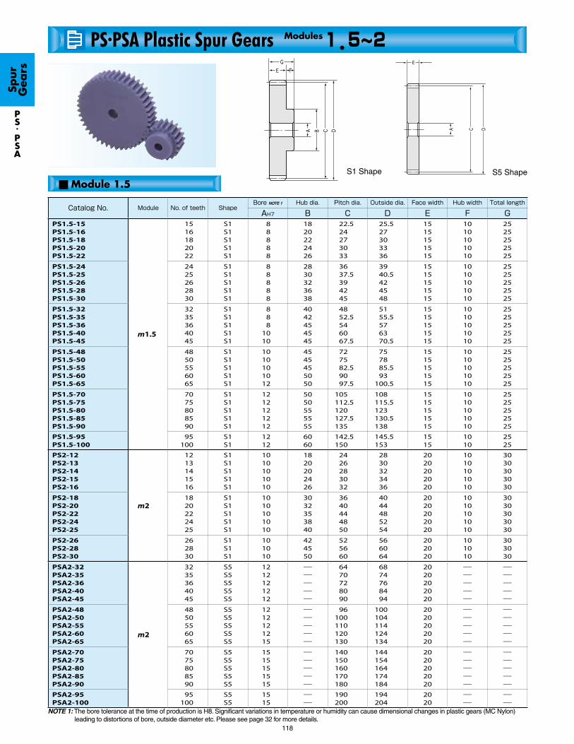
S5 Shape
PS.PSA
118
S1 Shape
■ Module 1.5
NOTE 1: The bore tolerance at the time of production is H8. Significant variations in temperature or humidity can cause dimensional changes in plastic gears (MC Nylon) leading to distortions of bore, outside diameter etc. Please see page 32 for more details.
Catalog No. Module No. of teeth ShapeBore NOTE 1 Hub dia. Pitch dia. Outside dia. Face width Hub width Total length
AH7 B C D E F GPS1.5-15PS1.5-16PS1.5-18PS1.5-20PS1.5-22
m1.5
1516182022
S1S1S1S1S1
88888
1820222426
22.524273033
25.527303336
1515151515
1010101010
2525252525
PS1.5-24PS1.5-25PS1.5-26PS1.5-28PS1.5-30
2425262830
S1S1S1S1S1
88888
2830323638
3637.5394245
3940.5424548
1515151515
1010101010
2525252525
PS1.5-32PS1.5-35PS1.5-36PS1.5-40PS1.5-45
3235364045
S1S1S1S1S1
888
1010
4042454545
4852.5546067.5
5155.5576370.5
1515151515
1010101010
2525252525
PS1.5-48PS1.5-50PS1.5-55PS1.5-60PS1.5-65
4850556065
S1S1S1S1S1
1010101012
4545455050
727582.59097.5
757885.593
100.5
1515151515
1010101010
2525252525
PS1.5-70PS1.5-75PS1.5-80PS1.5-85PS1.5-90
7075808590
S1S1S1S1S1
1212121212
5050555555
105112.5120127.5135
108115.5123130.5138
1515151515
1010101010
2525252525
PS1.5-95PS1.5-100
95100
S1S1
1212
6060
142.5150
145.5153
1515
1010
2525
PS2-12PS2-13PS2-14PS2-15PS2-16
m2
1213141516
S1S1S1S1S1
1010101010
1820202426
2426283032
2830323436
2020202020
1010101010
3030303030
PS2-18PS2-20PS2-22PS2-24PS2-25
1820222425
S1S1S1S1S1
1010101010
3032353840
3640444850
4044485254
2020202020
1010101010
3030303030
PS2-26PS2-28PS2-30
262830
S1S1S1
101010
424550
525660
566064
202020
101010
303030
PSA2-32PSA2-35PSA2-36PSA2-40PSA2-45
m2
3235364045
S5S5S5S5S5
1212121212
―――――
6470728090
6874768494
2020202020
―――――
―――――
PSA2-48PSA2-50PSA2-55PSA2-60PSA2-65
4850556065
S5S5S5S5S5
1212121215
―――――
96100110120130
100104114124134
2020202020
―――――
―――――
PSA2-70PSA2-75PSA2-80PSA2-85PSA2-90
7075808590
S5S5S5S5S5
1515151515
―――――
140150160170180
144154164174184
2020202020
―――――
―――――
PSA2-95PSA2-100
95100
S5S5
1515
――
190200
194204
2020
――
――
PS.PSA Plastic Spur Gears 1.5~2Modules
Spur
G
ears

Plastic Spur Gears
PS.PSA
119
NOTE 2: The allowable torques shown in the table are calculated values using the Lewis formula. Please see page 27 for more details.
NOTE 3: The backlash values shown in the table are the theoretical values of a pair of identical gears in mesh.
Allowable torque(N・m) NOTE 2Allowable torque(kgf・m) Backlash(mm)NOTE 3
Weight(kg)
Catalog No.Bending strength Bending strength
1.391.531.792.072.34
0.140.160.180.210.24
0.14~0.300.14~0.300.14~0.300.14~0.300.14~0.30
0.00900.0100.0130.0180.019
PS1.5-15PS1.5-16PS1.5-18PS1.5-20PS1.5-22
2.612.762.913.183.46
0.270.280.30.320.35
0.14~0.300.14~0.300.14~0.300.14~0.300.14~0.30
0.0280.0290.0300.0350.045
PS1.5-24PS1.5-25PS1.5-26PS1.5-28PS1.5-30
3.764.224.385.005.79
0.380.430.450.510.59
0.14~0.300.16~0.320.16~0.320.16~0.320.16~0.32
0.0450.0500.0590.0650.078
PS1.5-32PS1.5-35PS1.5-36PS1.5-40PS1.5-45
6.276.607.368.148.91
0.640.670.750.830.91
0.16~0.320.16~0.320.16~0.320.16~0.320.16~0.32
0.0860.0920.110.130.15
PS1.5-48PS1.5-50PS1.5-55PS1.5-60PS1.5-65
9.6910.511.312.012.8
0.991.071.151.231.31
0.18~0.360.18~0.360.18~0.360.18~0.360.18~0.36
0.170.190.220.250.27
PS1.5-70PS1.5-75PS1.5-80PS1.5-85PS1.5-90
13.614.4
1.391.47
0.18~0.360.18~0.36
0.300.34
PS1.5-95PS1.5-100
2.252.592.963.293.63
0.230.260.300.340.37
0.18~0.340.18~0.340.18~0.340.18~0.340.18~0.34
0.0110.0130.0150.0160.022
PS2-12PS2-13PS2-14PS2-15PS2-16
4.244.915.556.196.54
0.430.500.570.630.67
0.18~0.340.18~0.340.18~0.340.18~0.340.18~0.34
0.0290.0320.0430.0520.059
PS2-18PS2-20PS2-22PS2-24PS2-25
6.907.548.20
0.700.770.84
0.20~0.360.20~0.360.20~0.36
0.0620.0740.087
PS2-26PS2-28PS2-30
8.9110.010.411.913.7
0.911.021.061.211.40
0.20~0.360.20~0.360.20~0.360.20~0.360.20~0.36
0.0720.0860.0890.110.15
PSA2-32PSA2-35PSA2-36PSA2-40PSA2-45
14.915.717.519.321.1
1.521.601.781.972.15
0.20~0.360.20~0.360.22~0.380.22~0.380.22~0.38
0.160.180.220.280.30
PSA2-48PSA2-50PSA2-55PSA2-60PSA2-65
23.024.926.728.530.4
2.342.542.722.913.10
0.22~0.380.22~0.380.22~0.380.22~0.380.22~0.38
0.350.410.460.520.59
PSA2-70PSA2-75PSA2-80PSA2-85PSA2-90
32.334.2
3.293.48
0.22~0.380.22~0.38
0.650.72
PSA2-95PSA2-100
Spur
G
ears
Specifications
Precision grade
Gear teeth
Pressure angle
Material
Heat treatment
Standard full depth
20°
MC901
-
Tooth hardness
Surface treatment
Tooth surface finish
Secondary Operations
115~120HRR
-
Cut
Bore
JIS N9 grade (JIS B1702-1: 1998) OLD JIS 5 grade (JIS B1702: 1976)
Datum reference surface for gear cutting
Possible

PS.PSA
120
NOTE 1: The bore tolerance at the time of production is H8. Significant variations in temperature or humidity can cause dimensional changes in plastic gears (MC Nylon) leading to distortions of bore, outside diameter etc. Please see page 32 for more details.
S5 ShapeS1 Shape■ Module 2.5, 3
Catalog No. Module No. of teeth ShapeBore NOTE 1 Hub dia. Pitch dia. Outside dia. Face width Hub width Total length
AH7 B C D E F GPS2.5-12PS2.5-13PS2.5-14PS2.5-15PS2.5-16
1213141516
S1S1S1S1S1
1010101212
2325253032
3032.53537.540
3537.54042.545
2525252525
1212121212
3737373737
PS2.5-18PS2.5-20PS2.5-22PS2.5-24PS2.5-25
1820222425
S1S1S1S1S1
1212121212
3840444850
4550556062.5
5055606567.5
2525252525
1212121212
3737373737
PS2.5-26PS2.5-28PS2.5-30
262830
S1S1S1
121212
556065
657075
707580
252525
121212
373737
PSA2.5-32PSA2.5-35PSA2.5-36PSA2.5-40PSA2.5-45
3235364045
S5S5S5S5S5
1515151515
―――――
8087.590
100112.5
8592.595
105117.5
2525252525
―――――
―――――
PSA2.5-48PSA2.5-50PSA2.5-55PSA2.5-60
48505560
S5S5S5S5
15151515
――――
120125137.5150
125130142.5155
25252525
――――
――――
PS3-12PS3-13PS3-14PS3-15PS3-16
1213141516
S1S1S1S1S1
1212121414
2830323638
3639424548
4245485154
3030303030
1515151515
4545454545
PS3-18PS3-20PS3-22PS3-24PS3-25
1820222425
S1S1S1S1S1
1414141414
4050545860
5460667275
6066727881
3030303030
1515151515
4545454545
PS3-26PS3-28PS3-30
262830
S1S1S1
141414
657075
788490
849096
303030
151515
454545
PSA3-32PSA3-35PSA3-36PSA3-40PSA3-45 m3
3235364045
S5S5S5S5S5
1818181818
―――――
96105108120135
102111114126141
3030303030
―――――
―――――
PSA3-48PSA3-50PSA3-55PSA3-60
48505560
S5S5S5S5
18181818
――――
144150165180
150156171186
30303030
――――
――――
m2.5
m3
PS.PSA Plastic Spur Gears 2.5~3Modules
Spur
G
ears

Plastic Spur Gears
121
NOTE 2: The allowable torques shown in the table are calculated values using the Lewis formula.Please see page 27 for more details.
NOTE 3: The backlash values shown in the table are the theoretical values of a pair of identical gears in mesh.
Allowable torque(N・m) NOTE 2Allowable torque(kgf・m) Backlash(mm)NOTE 3
Weight(kg)
Catalog No.Bending strength Bending strength
4.395.065.776.427.09
0.450.520.590.650.72
0.20~0.360.20~0.360.20~0.360.20~0.360.20~0.36
0.0260.0270.0310.0340.037
PS2.5-12PS2.5-13PS2.5-14PS2.5-15PS2.5-16
8.289.59
10.812.112.8
0.840.981.111.231.30
0.20~0.360.20~0.360.22~0.380.22~0.380.22~0.38
0.0740.0650.0840.0960.10
PS2.5-18PS2.5-20PS2.5-22PS2.5-24PS2.5-25
13.514.716.0
1.371.501.63
0.22~0.380.22~0.380.22~0.38
0.120.150.18
PS2.5-26PS2.5-28PS2.5-30
17.419.520.323.226.8
1.771.992.072.362.73
0.22~0.380.22~0.380.22~0.380.22~0.380.24~0.40
0.160.160.170.180.28
PSA2.5-32PSA2.5-35PSA2.5-36PSA2.5-40PSA2.5-45
29.030.634.137.7
2.963.123.483.84
0.24~0.400.24~0.400.24~0.400.24~0.40
0.320.360.420.51
PSA2.5-48PSA2.5-50PSA2.5-55PSA2.5-60
7.588.749.97
11.112.3
0.770.891.021.131.25
0.28~0.440.28~0.440.28~0.440.28~0.440.28~0.44
0.040.0480.0560.0590.074
PS3-12PS3-13PS3-14PS3-15PS3-16
14.316.618.720.922.1
1.461.691.912.132.25
0.30~0.460.30~0.460.30~0.460.30~0.460.30~0.46
0.100.120.150.180.19
PS3-18PS3-20PS3-22PS3-24PS3-25
23.325.527.7
2.372.602.82
0.30~0.460.30~0.460.30~0.46
0.210.250.26
PS3-26PS3-28PS3-30
30.133.835.140.046.3
3.073.443.574.084.72
0.30~0.460.32~0.480.32~0.480.32~0.480.32~0.48
0.230.290.310.380.49
PSA3-32PSA3-35PSA3-36PSA3-40PSA3-45
50.252.858.965.1
5.125.396.016.64
0.32~0.480.32~0.480.32~0.480.32~0.48
0.550.530.730.88
PSA3-48PSA3-50PSA3-55PSA3-60
Spur
G
ears
PS.
PSA
Specifications
Precision grade
Gear teeth
Pressure angle
Material
Heat treatment
Standard full depth
20°
MC901
-
Tooth hardness
Surface treatment
Tooth surface finish
Secondary Operations
115~120HRR
-
Cut
Bore
JIS N9 grade (JIS B1702-1: 1998) OLD JIS 5 grade (JIS B1702: 1976)
Datum reference surface for gear cutting
Possible

122
NOTE 1: The bore tolerance is generally -0.05 to -0.1 but may be + values at the central portion of the hole. Re-machining the bore is not recommended since reworking material may expose voids.
Catalog No. Module No. of teeth ShapeBore 1 NOTE 1 Bore 2 Hub dia. 1 Hub dia. 2 Pitch dia. Outside dia. Face width Hub width
A A' B B' C D E FDS0.5-12DS0.5-15DS0.5-16DS0.5-18DS0.5-20
m0.5
1215161820
S8S8S8S8S9
22334
4567―
4.54.5668
――――5
67.589
10
78.59
1011
33333
44444
DS0.5-24DS0.5-25DS0.5-28DS0.5-30DS0.5-32
2425283032
S9S9S9S9S9
44455
―――――
888
1010
56677
1212.5141516
1313.5151617
33333
44444
DS0.5-35DS0.5-36DS0.5-40DS0.5-45DS0.5-48
3536404548
S9S9S9S9S9
55555
―――――
1010121212
77888
17.5182022.524
18.5192123.525
33333
44444
DS0.5-50DS0.5-56DS0.5-60DS0.5-64DS0.5-70
5056606470
S9S9S9S9S9
56666
―――――
1214141414
810101010
2528303235
2629313336
33333
45555
DS0.5-72DS0.5-80
7280
S9S9
66
――
1414
1010
3640
3741
33
55
DS0.8-12DS0.8-15DS0.8-16DS0.8-18DS0.8-20
m0.8
1215161820
S9S9S9S9S9
33445
―――――
6688
10
45668
9.61212.814.416
11.213.614.41617.6
44444
55555
DS0.8-24DS0.8-25DS0.8-28DS0.8-30DS0.8-32
2425283032
S9S9S9S9S9
55566
―――――
1010101212
888
1010
19.22022.42425.6
20.821.62425.627.2
44444
55555
DS0.8-35DS0.8-36DS0.8-40DS0.8-45DS0.8-48
3536404548
S9S9S9S9S9
66666
―――――
1212121214.5
1010101011.7
2828.8323638.4
29.630.433.637.640
44444
55556
DS0.8-50DS0.8-56DS0.8-60DS0.8-64DS0.8-70
5056606470
S9S9S9S9S9
66666
―――――
14.514.514.515.515.5
11.711.711.711.711.7
4044.84851.256
41.646.449.652.857.6
44444
66666
DS0.8-72DS0.8-80
7280
S9S9
66
――
15.515.5
11.711.7
57.664
59.265.6
44
66
Spur
G
ears
DS
■ Module 0.5, 0.8
DS Injection Molded Spur Gears 0.5~0.8Modules
S9 Shape
S8 Shape

Injection Molded Spur Gears
DS
123
NOTE 2: The allowable torques shown in the table are calculated values using the Lewis formula. Please see page 27 for more details.NOTE 3: The backlash values shown in the table are the theoretical values of a pair of identical gears in mesh.
Total length Web thickness Web O.D. Depth of counterbore Allowable torque(N・m) NOTE 2 Allowable torque(kgf・m) Backlash(mm)NOTE 3
Weight(kg)
Catalog No.G H I J Bending strength Bending strength
77777
――――
2.4
――――8
0.60.60.60.6―
0.063 0.092 0.10 0.12 0.14
0.0064 0.0094 0.010 0.012 0.014
0.05~0.300.05~0.300.05~0.300.05~0.300.05~0.30
11111
DS0.5-12DS0.5-15DS0.5-16DS0.5-18DS0.5-20
77777
1.81.81.81.81.8
9.510121213
―――――
0.17 0.18 0.21 0.23 0.25
0.018 0.019 0.022 0.023 0.025
0.05~0.300.05~0.300.05~0.300.05~0.300.05~0.30
11111
DS0.5-24DS0.5-25DS0.5-28DS0.5-30DS0.5-32
77777
1.81.81.81.81.8
14.515171921
―――――
0.28 0.29 0.33 0.38 0.42
0.029 0.030 0.034 0.039 0.043
0.05~0.300.05~0.300.05~0.300.05~0.300.05~0.30
11122
DS0.5-35DS0.5-36DS0.5-40DS0.5-45DS0.5-48
78888
1.81.81.81.81.8
2224.526.528.531.5
―――――
0.44 0.50 0.54 0.58 0.64
0.045 0.051 0.055 0.059 0.066
0.05~0.300.05~0.300.05~0.300.05~0.300.05~0.30
23334
DS0.5-50DS0.5-56DS0.5-60DS0.5-64DS0.5-70
88
1.81.8
32.536.5
――
0.67 0.75
0.068 0.076
0.05~0.300.05~0.30
45
DS0.5-72DS0.5-80
99999
22222
6.78.89.2
10.712.7
―――――
0.22 0.31 0.35 0.41 0.47
0.022 0.032 0.035 0.041 0.048
0.08~0.480.08~0.480.08~0.480.08~0.480.08~0.48
11112
DS0.8-12DS0.8-15DS0.8-16DS0.8-18DS0.8-20
99999
22222
15.515.5192021.7
―――――
0.59 0.63 0.72 0.79 0.85
0.060 0.064 0.074 0.080 0.087
0.08~0.480.08~0.480.08~0.480.08~0.480.08~0.48
22233
DS0.8-24DS0.8-25DS0.8-28DS0.8-30DS0.8-32
9999
10
22222
242528.33234.3
―――――
0.96 0.99 1.13 1.31 1.42
0.098 0.10 0.12 0.13 0.15
0.08~0.480.08~0.480.08~0.480.08~0.480.08~0.48
33445
DS0.8-35DS0.8-36DS0.8-40DS0.8-45DS0.8-48
1010101010
22222
36414445.552
―――――
1.50 1.70 1.85 1.98 2.20
0.15 0.17 0.19 0.20 0.22
0.08~0.480.08~0.480.08~0.480.08~0.480.08~0.48
67889
DS0.8-50DS0.8-56DS0.8-60DS0.8-64DS0.8-70
1010
22
5460
――
2.27 2.55
0.23 0.26
0.08~0.480.08~0.48
1012
DS0.8-72DS0.8-80
Specifications
Precision grade
Gear teeth
Pressure angle
Material
Heat treatment
Standard full depth
20°
DURACON acetal (M90-44)
-
Tooth hardness
Surface treatment
Tooth surface finish
Secondary Operations
110~120HRR
-
Injection molded
Bore
JIS N12 grade (JIS B1702-2: 1998) OLD JIS 8 grade (JIS B1702: 1976)
Datum reference surface for tooth forming
Please avoid reworking material as this may expose voids.
Spur
G
ears
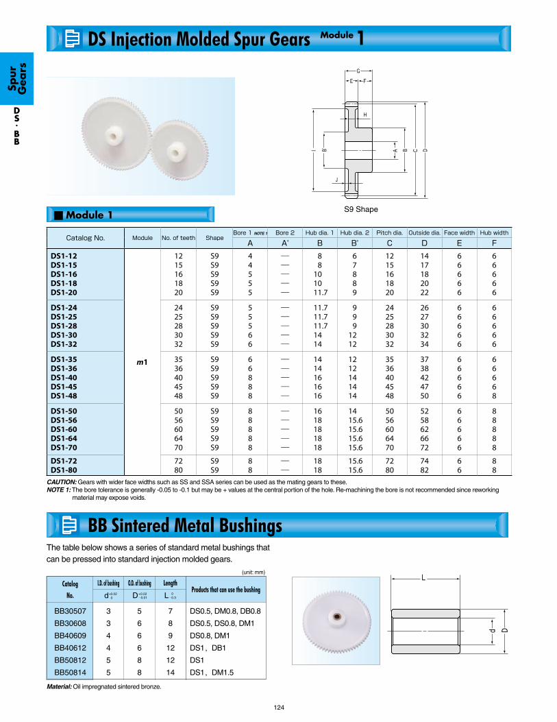
BB30507
BB30608
BB40609
BB40612
BB50812
BB50814
DS0.5, DM0.8, DB0.8
DS0.5, DS0.8, DM1
DS0.8, DM1
DS1, DB1
DS1
DS1, DM1.5
DS.BB
124
The table below shows a series of standard metal bushings that can be pressed into standard injection molded gears.
3
3
4
4
5
5
5
6
6
6
8
8
7
8
9
12
12
14
L 0-0.3
Material: Oil impregnated sintered bronze.
S9 Shape
CAUTION: Gears with wider face widths such as SS and SSA series can be used as the mating gears to these.NOTE 1: The bore tolerance is generally -0.05 to -0.1 but may be + values at the central portion of the hole. Re-machining the bore is not recommended since reworking
material may expose voids.
d+0.020 D+0.02
-0.01
(unit: mm)
Spur
G
ears
■ Module 1
DS Injection Molded Spur Gears 1Module
BB Sintered Metal Bushings
Catalog
No.
I.D. of bushing LengthO.D. of bushingProducts that can use the bushing
Catalog No. Module No. of teeth ShapeBore 1 NOTE 1 Bore 2 Hub dia. 1 Hub dia. 2 Pitch dia. Outside dia. Face width Hub width
A A' B B' C D E FDS1-12DS1-15DS1-16DS1-18DS1-20
m1
1215161820
S9S9S9S9S9
44555
―――――
88
101011.7
67889
1215161820
1417182022
66666
66666
DS1-24DS1-25DS1-28DS1-30DS1-32
2425283032
S9S9S9S9S9
55566
―――――
11.711.711.71414
999
1212
2425283032
2627303234
66666
66666
DS1-35DS1-36DS1-40DS1-45DS1-48
3536404548
S9S9S9S9S9
66888
―――――
1414161616
1212141414
3536404548
3738424750
66666
66668
DS1-50DS1-56DS1-60DS1-64DS1-70
5056606470
S9S9S9S9S9
88888
―――――
1618181818
1415.615.615.615.6
5056606470
5258626672
66666
88888
DS1-72DS1-80
7280
S9S9
88
――
1818
15.615.6
7280
7482
66
88

±0.2
Tolerance
±0.5
±0.40
±0.35
±0.3
±0.25
NOTE 2: The allowable torques shown in the table are calculated values using the Lewis formula. Please see page 27 for more details.NOTE 3: The backlash values shown in the table are the theoretical values of a pair of identical gears in mesh.
Injection Molded Spur Gears
DS
125
■ Tolerance of Injection Molded Products (unit: mm)
Range
below 3
3 up to 6
6 up to 10
10 up to 18
18 up to 30
30 up
Total length Web thickness Web O.D. Depth of counterbore Allowable torque(N・m) NOTE 2 Allowable torque(kgf・m) Backlash(mm)NOTE 3
Weight(kg)
Catalog No.G H I J Bending strength Bending strength
1212121212
33333
8.51111.513.515
―――――
0.44 0.65 0.71 0.83 0.96
0.045 0.066 0.073 0.085 0.098
0.10~0.600.10~0.600.10~0.600.10~0.600.10~0.60
12223
DS1-12DS1-15DS1-16DS1-18DS1-20
1212121212
33333
1720232426.5
―――――
1.22 1.28 1.48 1.61 1.75
0.12 0.13 0.15 0.16 0.18
0.10~0.600.10~0.600.10~0.600.10~0.600.10~0.60
44456
DS1-24DS1-25DS1-28DS1-30DS1-32
1212121214
33333
29303439.540
―――――
1.96 2.04 2.33 2.69 2.92
0.20 0.21 0.24 0.27 0.30
0.10~0.600.10~0.600.10~0.600.10~0.600.10~0.60
6689
11
DS1-35DS1-36DS1-40DS1-45DS1-48
1414141414
33333
42.548.552.556.562.5
―――――
3.07 3.49 3.78 4.07 4.50
0.31 0.36 0.39 0.41 0.46
0.10~0.600.10~0.600.10~0.600.10~0.600.10~0.60
1215161821
DS1-50DS1-56DS1-60DS1-64DS1-70
1414
33
6472.5
――
4.65 5.23
0.47 0.53
0.10~0.600.10~0.60
2126
DS1-72DS1-80
Spur
G
ears
Specifications
Precision grade
Gear teeth
Pressure angle
Material
Heat treatment
Standard full depth
20°
DURACON acetal (M90-44)
-
Tooth hardness
Surface treatment
Tooth surface finish
Secondary Operations
110~120HRR
-
Injection molded
Bore
JIS N12 grade (JIS B1702-2: 1998) OLD JIS 8 grade (JIS B1702: 1976)
Datum reference surface for tooth forming
Please avoid reworking material as this may expose voids.

BSS
126
BSS0.5-20BSS0.5-25BSS0.5-30BSS0.5-40
0.50.50.50.5
z20253040
AH7
4444
B08.511.013.017.0
C10.012.515.020.0
11.013.516.021.0
3333
7777
10101010
S1S1S1S1
0.0910.120.160.23
(0.0093)(0.013)(0.016)(0.024)
0~0.1 0~0.10 0~0.10
0~0.1
04081120
BSS0.8-20BSS0.8-25BSS0.8-30BSS0.8-40
0.80.80.80.8
20253040
5555
13.517.020.020.0
16202432
17.621.625.633.6
4444
8888
12121212
S1S1S1S1
0.310.430.550.79
(0.032)(0.043)(0.056)(0.081)
0~0.1 0~0.10 0~0.10
0~0.1
14243446
NOTE 1: The allowable torques shown in the table are the calculated values according to the assumed usage conditions. Please see page 27 for more details.NOTE 2: The backlash values shown in the table are the theoretical values of a pair of identical gears in mesh.
S1 Shape
BSS Brass Spur Gears 0.5~0.8Modules
■ Module 0.5
■ Module 0.8
Catalog
No.
Module
m G
Total length
F
Hub width
E
Face width
D
Outside dia.Hub dia. Pitch dia.Bore No. of teethShape
Allowable torque (N.m)NOTE 1
Bending strength
Allowable torque(kgf.m)
Bending strength
Backlash (mm)NOTE 2
Weight
(gf)
Spur
G
ears
Specifications
Standard full depth 20°Free cutting brass (C3604BD-F)-Less than 80HRR-CutBore
JIS N8 grade (JIS B1702-1: 1998) OLD JIS 4 grade (JIS B1702: 1976)
Possible
Precision grade
Tooth hardnessSurface treatmentTooth surface finish
Secondary Operations
Datum reference surface forgear cutting
Gear teethPressure angleMaterialHeat treatment

SSR
127
NOTE 1: Although the inside diameter of these gears are made to H8 tolerance, since the ring shape is easily deformed, some error may occur beyond the stated tolerance.
NOTE 2: The allowable torques shown in the table are the calculated values according to the assumed usage conditions. Please see page 27 for more details.NOTE 3: The backlash values shown in the table are the theoretical values of a pair of identical gears in mesh.
S5 Shape
Backlash(mm)NOTE 3
Weight(kg)
Catalog No.
0.17~0.370.20~0.41
2.504.30
SSR2-120SSR2-200
0.19~0.410.22~0.46
4.608.00
SSR2.5-120SSR2.5-200
0.22~0.450.22~0.45
7.8010.6
SSR3-120SSR3-160
Catalog No. Module No. of teeth ShapeBore NOTE 1 Pitch dia. Outside dia. Face width Allowable torque(N・m) NOTE 2 Allowable torque(kgf・m)
AH8 C D E Bending strength Surface durability Bending strength Surface durability
SSR2-120SSR2-200
m2120200
S5S5
194354
240400
244404
2020
366630
44.084.2
37.464.3
4.498.59
SSR2.5-120SSR2.5-200
m2.5120200
S5S5
245445
300500
305505
2525
7151230
88.5169
72.9126
9.0217.2
SSR3-120SSR3-160
m3120160
S5S5
296416
360480
366486
3030
12401680
157226
126171
16.023.0
Specifications
Standard full depth 20°S45C-Less than 194HB-CutBore
JIS N9 grade (JIS B1702-1: 1998) OLD JIS 5 grade (JIS B1702: 1976)
Possible
Spur
G
ears
■ Module 2, 2.5, 3
SSR Steel Ring Gears (Spur Gears) 2~3Modules
Precision grade
Tooth hardnessSurface treatmentTooth surface finish
Secondary Operations
Datum reference surface forgear cutting
Gear teethPressure angleMaterialHeat treatment