Table of Contents - TPC Training · also recovery of reasonable attorneys’ fees. ... Induction...
19
PREVIEW COPY Table of Contents Lesson One Introduction to Single-Phase Motors................................................3 Lesson Two Split-Phase Motors.........................................................................21 Lesson Three Capacitor Motors............................................................................37 Lesson Four Repulsion Motors...........................................................................55 Lesson Five Universal Motors............................................................................71 Lesson Six Special Motors................................................................................87 Lesson Seven Synchros.......................................................................................103 Lesson Eight Servos...........................................................................................121 Lesson Nine Motor Installation.........................................................................139 Lesson Ten Motor Maintenance......................................................................157 © Copyright 1983, 2001, 2006 by TPC Training Systems, a division of Telemedia, Inc. All rights reserved, including those of translation. Printed and videotaped courseware are subject to the copyright laws of the United States. You are not autho- rized to make any copies of this material. If you do, then you are subject to the penalties provided under the copyright law, which include statutory damages up to $50,000 for each infringement of copyrighted material, and also recovery of reasonable attorneys’ fees. Further, you could be subject to criminal prosecution pursuant to 18 U.S.C. § 2319. 06-1
-
Upload
nguyenduong -
Category
Documents
-
view
215 -
download
0
Transcript of Table of Contents - TPC Training · also recovery of reasonable attorneys’ fees. ... Induction...

PREVIEW
COPY
Table of Contents
Lesson One Introduction to Single-Phase Motors................................................3
Lesson Two Split-Phase Motors.........................................................................21
Lesson Three Capacitor Motors............................................................................37
Lesson Four Repulsion Motors...........................................................................55
Lesson Five Universal Motors............................................................................71
Lesson Six Special Motors................................................................................87
Lesson Seven Synchros.......................................................................................103
Lesson Eight Servos...........................................................................................121
Lesson Nine Motor Installation.........................................................................139
Lesson Ten Motor Maintenance......................................................................157
© Copyright 1983, 2001, 2006 by TPC Training Systems, a division of Telemedia, Inc.
All rights reserved, including those of translation.
Printed and videotaped courseware are subject to the copyright laws of the United States. You are not autho-rized to make any copies of this material. If you do, then you are subject to the penalties provided under thecopyright law, which include statutory damages up to $50,000 for each infringement of copyrighted material, andalso recovery of reasonable attorneys’ fees. Further, you could be subject to criminal prosecution pursuant to 18U.S.C. § 2319.
06-1

SINGLE-PHASE MOTORS
Lesson One
Introduction toSingle-Phase Motors
20701
PREVIEW
COPY

PREVIEW
COPY
1
4
Lesson
Introduction to Single-PhaseMotors
Parts of a Single-Phase MotorDefinitionsNEMA Motor StandardsMotor EnclosuresNameplate DataInduction MotorsSingle-Phase Stator Field
Single-Phase Rotor FieldSplit-Phase StartingNumber of PolesElectrical DegreesSynchronous SpeedStarting SwitchesStandard and Special Split-Phase Motors
TOPICS
After studying this lesson, you should be able to…
• List the parts of a rotor.• List the data given on a typical motor nameplate.• Explain how an induction motor works.
• Demonstrate how to calculate the number of elec-trical degrees in one complete rotation of a motor.
• Explain how a centrifugal switch works.
OBJECTIVES
Rotor 1.01 the rotating part of a motor or generatorStator 1.01 the stationary part of a motor or gen-
eratorService factor 1.07 the allowable overload of a
general-purpose motorSlip speed 1.07 the difference between a motor’s
synchronous speed and its operating speed
Phase splitting 1.39 the production of a rotatingmagnetic field by using two stator windings with adifferent impedance to create a difference inphase
Synchronous speed 1.51 the speed of the rotat-ing magnetic field in an induction motor
KEY TECHNICAL TERMS

Rotor
Statorwinding
Bearing
End plate
Air shield
Stator core
End plate
Frame
PREVIEW
COPY
Parts of a Single-Phase Motor
1.01 The single-phase fractional-horsepower acmotor is used in many industrial applications. It dri-ves fans, pumps, clocks, and power tools. Every sin-gle-phase motor has a rotating part, called the rotor,and a stationary part, called the stator. End platesbolted to the stator frame support the bearings for therotor shaft. Figure 1-1 shows the parts of a single-phase motor.
1.02 The rotor consists of three elements—thecore, the squirrel cage, and the shaft. The core ismade of sheet-steel laminations to keep the eddy cur-rents to a minimum. The assembled core is pressedonto the shaft. A squirrel-cage , made of heavy bars ofcopper or aluminum, is embedded in slots cut in the
core. The bars are connected to each other by a ringof copper or aluminum around each end of the core.The rings provide electrical continuity by short-cir-cuiting all the bars at the ends.
1.03 The name “squirrel cage” comes from theappearance of the rotor winding. Separated from therotor core, the bars and connecting rings make astructure that looks like the exercise wheel in a cagefor squirrels. This structure is shown in Fig. 1-2, onthe following page.
1.04 The stator core is made of sheet-steel lamina-tions pressed into a frame made of steel or cast iron.The core has slots that are partially closed. Coils ofcopper wire fit into the slots. These coils make up thestator winding.
5
Single-phase fractional horsepower ac motors are widely used in the plant. Usesinclude driving fans, pumps, clocks, and many types of power tools. Single-phase motors are divided into various classifications, some or all of which youmay find in your plant.
This lesson introduces you to many terms associated with single-phase acmotors. Do not let the number of definitions confuse you. Many will be used inthe other lessons in this course, and you will become familiar with them.
This lesson explains the fundamentals of single-phase motors. This informationcovers stator and rotor fields, split-phase starting, magnetic poles, electricaldegrees, synchronous speed, starting switches, and standard and special split-phase motors.
Fig. 1-1. Parts of a single-phase ac motor

PREVIEW
COPY
1.05 The end plates (also called end shields, endbells, or end housings) are bolted to the stator frame.The end-plate bearings support the rotor and keep itcentered within the stator.
Definitions
1.06 In order to understand the information in thiscourse you must learn the meanings of certain motordescriptions. The following descriptions define vari-ous classifications of motors.
• General-purpose motor. Any open-enclosuremotor having a continuous 40°C rating anddesigned, listed, and offered in standard rat-ings, with standard operating characteristicsand mechanical construction, for use underordinary service conditions without restrictionto a specific application or kind of application.
• Definite-purpose motor. Any motordesigned, listed, and offered in standard rat-ings, with standard operating characteristicsor mechanical construction, for use under ser-vice conditions other than ordinary conditionsor for use in a specific kind of application.
• Special-purpose motor. A motor with specialoperating characteristics or special mechani-cal construction (or both), designed for a spe-cific application.
• Split-phase motor. A single-phase inductionmotor with an auxiliary winding displaced inmagnetic position from the main winding andconnected in parallel with the main winding.
• Capacitor-start motor. A single-phase induc-tion motor with a main winding arranged fordirect connection to the power source and anauxiliary winding connected in series with acapacitor. The auxiliary winding with thecapacitor is in the circuit only during starting.
• Capacitor-run motor. A single-phase induc-tion motor similar to the capacitor-startmotor. However, in this motor the capacitorremains in the circuit for both starting andrunning.
• Shaded-pole motor. A single-phase inductionmotor having one or more short-circuitedauxiliary windings. The windings are dis-placed in magnetic position from the mainwinding to provide the rotation of the mag-netic field.
1.07 In addition to understanding the definitions ofvarious kinds of motors, you need to know how sev-eral terms are defined. The following terms are usedin describing the operating characteristics of motors.
• Locked-rotor torque. The minimum torquedeveloped by a motor with its rotor locked inall possible angular positions, when the motorreceives its rated potential difference at therated frequency.
• Breakdown torque. The maximum torque amotor can produce at its rated potential differ-ence and frequency, without an abruptdecrease in speed.
• Full-load torque. The torque produced by amotor when it delivers its rated power at itsfull-load speed.
• Pull-up torque. The minimum torque devel-oped by the motor as it accelerates from restto full speed.
• Service factor. The allowable overload of ageneral-purpose motor. It is expressed as anumber equal to the ratio of the permissibleoperating power to the rated power.
• Slip speed. The difference between a motor’ssynchronous speed and its operating speed.
6 Lesson One
Fig. 1-2. Squirrel cage

W
N
N - WV
XE
FFB
BA
A
A
D
E
U
XDXC
SECTIONTHROUGHSHAFTH DIA.
4 HOLES
E
Framenumber A B D E F BA H N-W U V min. XC XD XE
145T
184T
213T
7 in.
9
101/2
6
71/2
71/2
31/2
41/2
51/4
23/4
33/4
41/4
21/2
23/4
23/4
21/4
23/4
31/2
21/4
23/4
33/8
13/8
13/4
23/8
2
21/2
31/8
7/8
11/8
13/8
11/32
13/32
13/32
3/16
1/4
5/16
3/16
1/4
5/16
PREVIEW
COPY
• Locked-rotor current. The steady current inthe motor when the rotor is locked in positionand the rated potential difference and fre-quency are applied.
NEMA Motor Standards
1.08 Many motors are manufactured according tostandards set by the National Electrical ManufacturersAssociation (NEMA). A standard motor made by onemanufacturer can be replaced by the same standardmotor made by another manufacturer. The motor rat-ings, operating characteristics, and mechanical con-struction and dimensions are identical for all motorsmanufactured according to NEMA standards.
1.09 Standard motors are identified by a framenumber. For example, all motors identified by theframe number 145T have the same physical dimen-sions. Figure 1-3 is a drawing of a motor with lettereddimensions. The table below the drawing lists thedimensions for foot-mounted ac motors. The dimen-sions for three frame numbers are listed as examples.
1.10 The drawing and table in Fig. 1-3 identify thefollowing dimensions by letter. Three examples arelisted with all dimensions specified.
A = maximum width of base
B = maximum length of base
D = height of shaft center above lower bot-tom of base
E = radial distance of center of mounting hole from centerline of shaft
F = axial distance of center of mounting hole from center of frame
BA = axial distance of center of mounting hole from front surface of collar
H = diameter of holes in mounting base
N = overall length of exposed shaft
W = thickness of shaft collar
N-W = overall length of exposed shaft, minusthickness of collar
U = diameter of shaft
Introduction to Single-Phase Motors 7
Fig. 1-3. NEMA motor dimensions

PREVIEW
COPY
V = maximum width for mounting a pulley or sprocket
XC = width of keyway
XD = depth of keyway
XE = length of keyway
1.11 Table 1-1 is a list of the NEMA standard des-ignations of potential difference for ac motors andsupply systems. AC motors are designed to operate at±10% of their rated potential difference, and ± 5% oftheir rated frequency.
• A motor rated at a potential difference of 115V is designed to operate at a minimum of103.5 V and a maximum of 126.5 V.
• A motor rated at a frequency of 60 Hz isdesigned to operate at a minimum of 57 Hzand a maximum of 63 Hz.
1.12 There is nothing you can do to affect the fre-quency of the incoming ac power. Public utility com-panies control the frequency very accurately.
Motor Enclosures
1.13 There are two general classifications of motorenclosures—the open motor and the totally enclosedmotor.
1.14 Open motors. These motors have openingsto allow air to pass through and cool the windings.The openings are usually located in the end plates.
1.15 Open motors are further classified into thefollowing categories:
• Dripproof motors are designed to preventsolid particles and drops of liquid from enter-ing the motor at any angle up to 15° from thevertical, as shown at the left in Fig. 1-4.
• Splashproof motors prevent solid particlesand drops of liquid from entering the motor atany angle up to 100° from the vertical, asshown at the right in Fig. 1-4.
• Semiguarded or guarded motors have open-ings that are covered with a screen or grill toprevent accidental contact with rotating parts.
• Dripproof, fully guarded motors are a combi-nation of a dripproof motor and a guardedmotor.
• Open, externally ventilated motors are cooledby outside air coming from an external fan orfrom a metal duct.
• Open, pipe-ventilated motors are cooled byair that enters the motor through piping.
• Weather-protected motors have ventilatingopenings designed to minimize the entranceof rain, snow, and dust.
1.16 Totally enclosed motors. These motors areenclosed tightly enough to prevent air from enteringthe enclosure. However, the motors are not sealedtightly enough to be considered “airtight.” There areseveral classifications of these motors.
8 Lesson One
115200230460575
Table 1-1. NEMA standard voltages
System voltage
Motor voltage
Single phase Polyphase
120120/208Y
240480600
115115230--
15° 15°
100° 100°
Dripproof Splashproof
Fig. 1-4. Motor enclosures

PREVIEW
COPY
• Totally enclosed, nonventilated motors arecooled by the surrounding air.
• Totally enclosed, fan-cooled motors have afan mounted on one end of the motor shaft tocool the motor by forcing air over it when itis running.
• Explosionproof motors are used in locationswhere flammable vapors exist.
• Dust ignitionproof motors are used in grainelevators and other areas where dust existsand must not be ignited.
• Waterproof motors can operate even whensubmerged in water.
• Totally enclosed, pipe-ventilated motors arecooled by air forced through a pipe.
• Totally enclosed, water-cooled motors have aspecial jacket surrounding them. Water circu-lates through the jacket to remove heat.
Nameplate Data
1.17 All performance information for a motor isbased on the motor being supplied by power at thepotential difference and frequency stated on thenameplate. A motor rating consists of the power out-put, speed, potential difference, and current specifiedby the manufacturer.
1.18 A typical motor nameplate is shown in Fig.1-5. It includes the following information, labeledby numbers in the figure.
1. NEMA designation indicates the torque andcurrent characteristics. The most commondesignations are A, B, C, and D.
NEMA Starting Starting Breakdown Slip atletter torque current torque full load
A Normal Normal High LowB Normal Low High LowC High Low Normal LowD Very high Low — — — High
2. Phase indicates the kind of power the motoris designed for. Some motors operate on sin-gle-phase ac power, others on three-phase acpower, and still others on dc power.
3. Hertz indicates the frequency of the ac powerrequired to run the motor properly. This fre-quency is almost always 60 Hz in the UnitedStates and Canada. You may sometimes seemotors rated for 50 Hz for use in other coun-tries of the world.
4. Serial is the manufacturer’s code number thatidentifies the motor. It may indicate a generalkind of motor sold to many customers, it mayindicate a specific kind of motor built for onecustomer only, or it may indicate only thedate the motor was manufactured.
5. RPM is the speed of the motor at its ratedpower, when running on its rated potentialdifference and frequency. The speed is mea-sured in revolutions per minute (rpm). Smallmotors generally run at one of four speeds,depending on how many poles they have—3450 rpm (two pole), 1735 rpm (four pole),1140 rpm (six pole), and 825 rpm (eightpole).
6. Frame size is defined by NEMA. The mostcommon frame sizes for small motors are 42,
Introduction to Single-Phase Motors 9
1 2
16
3
4
6 8
18
14
1517
5
79101112
13
Fig. 1-5. Motor nameplate

PREVIEW
COPY
48, and 56. Medium motor frame sizes are143T through 149T.
7. Time hours indicates how long the motor maybe operated at one time without overheating.For most motors, the rating is continuous.That is, the motor can run continuously with-out overheating.
8. Insulation class indicates the class of insu-lation used in the motor. The classes aredefined by NEMA according to the maxi-mum temperatures the insulation can with-stand.
Class Maximum temperature
A..................................... 105°C 221°FB...................................... 130 266F...................................... 155 311H...................................... 180 356
9. KVA code is a letter indicating the locked-rotor power input (measured in kilowatts) perhorsepower of rated output. This letter isbased on a NEMA code. For example, the let-ter M indicates a locked-rotor power of 10.0to 11.2 kW per horsepower.
10. Model is a NEMA letter code. The first letterindicates the type of motor (T is the NEMAframe designation). The second letter indi-cates the kind of enclosure (FC indicates atotally enclosed fan-cooled motor).
11. User or catalog number is used by the manu-facturer or user to identify the motor.
12. Motor style number is the manufacturer’sspecification code. It identifies a set of draw-ings and electrical specifications necessary tomanufacture the motor.
13. Bearings are identified by number. Any bear-ing supply house can identify and supply areplacement bearing from this number.
14. Amps indicates the normal current drawn atthe motor’s rated load, potential difference,and frequency.
15. Volts indicates the potential difference of thepower supply for the motor.
16. Ambient temperature is the temperature in theimmediate location of the motor. The stan-dard is 40°C (104°F).
17. Service factor indicates how much the motormay be overloaded when operating at itsrated potential difference and frequency.
18. Horsepower is the amount of power themotor can produce at its rated speed.
Induction Motors
1.19 The basic idea of an induction motor isshown in Fig. 1-6. A disk of aluminum or other non-magnetic metal is mounted on an axis of rotation. Amagnet is also mounted so that it can rotate on thesame axis without touching the disk.
1.20 When the magnet rotates near the disk, itinduces an electric current in the disk, just as it wouldinduce a current in a wire. You can think of the diskas a wire having an infinite width—a wire that neverpasses out of the region near the magnet.
1.21 You can figure out the direction of theinduced current by using the left-hand rule for genera-tors. In applying the rule, you must pay close atten-tion to the relative motion between the magnet andthe disk.
10 Lesson One
Rotationof magnet
Induced current
Rotation of disk
Rotation of diskrelative to magnet
N S
Fig. 1-6. Principle of the induction motor

PREVIEW
COPY
• The magnet and the disk both rotate in thesame direction relative to stationary objectsoutside the motor.
• The magnet rotates faster than the disk.Therefore, the disk rotates backward relativeto the magnet.
1.22 The current induced in the disk passesthrough the magnetic field of the magnet. Therefore,the magnetic field exerts a force on the disk. Thisforce causes the disk to rotate, just as it causes thearmature to rotate in a motor that receives electriccurrent from an outside source.
1.23 The disk can never attain the speed of themagnet. If it did, there would be no relative motionbetween them. Without this relative motion no currentwould be induced in the disk, and no force wouldkeep the disk rotating. The speed of the relativemotion is called slip speed.
The Programmed Exercises on the following pagewill tell you how well you understand the materialyou have just read. Before starting the exercises,remove the Reveal Key from the back of yourbook. Read the instructions printed on the RevealKey. Follow these instructions as you workthrough the Programmed Exercises.
Introduction to Single-Phase Motors 11
PREVIEW
COPY
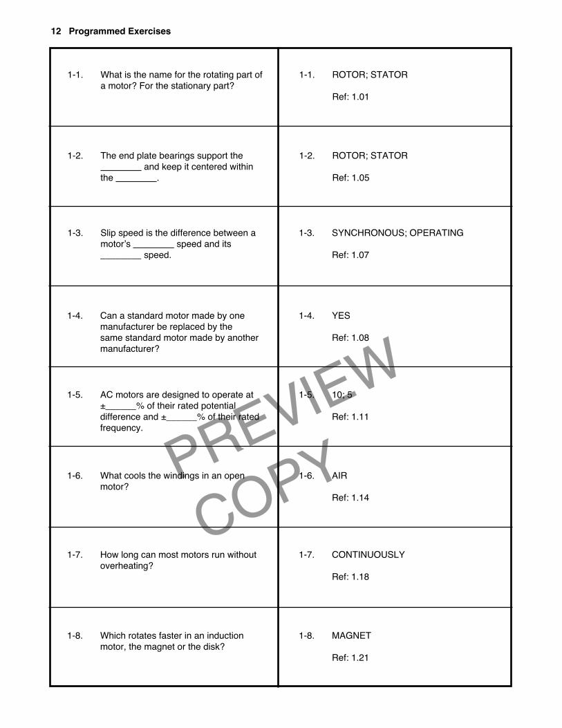
1-1. What is the name for the rotating part ofa motor? For the stationary part?
1-2. The end plate bearings support the________ and keep it centered withinthe ________.
1-3. Slip speed is the difference between amotor’s ________ speed and its________ speed.
1-4. Can a standard motor made by onemanufacturer be replaced by the same standard motor made by anothermanufacturer?
1-5. AC motors are designed to operate at±______% of their rated potential difference and ±______% of their ratedfrequency.
1-6. What cools the windings in an openmotor?
1-7. How long can most motors run withoutoverheating?
1-8. Which rotates faster in an inductionmotor, the magnet or the disk?
1-1. ROTOR; STATOR
Ref: 1.01
1-2. ROTOR; STATOR
Ref: 1.05
1-3. SYNCHRONOUS; OPERATING
Ref: 1.07
1-4. YES
Ref: 1.08
1-5. 10; 5
Ref: 1.11
1-6. AIR
Ref: 1.14
1-7. CONTINUOUSLY
Ref: 1.18
1-8. MAGNET
Ref: 1.21
12 Programmed Exercises

PREVIEW
COPY
Introduction to Single-Phase Motors 13
Single-Phase Stator Field
1.24 A symmetrically wound single-phase induc-tion motor cannot start by itself. However, once it isstarted by something else it will continue running.
1.25 Starting the motor requires a second winding,called the start winding. The winding that keeps themotor running after it starts is called the run winding.The start winding has higher resistance than the runwinding. Single-phase motors are classified accordingto the starting method used. These methods are calledthe split-phase, repulsion start, and shaded-polemethods.
1.26 When a single-phase potential difference isapplied across the stator winding of a single-phaseinduction motor, it produces an alternating current inthe winding. The current produces a magnetic field,as shown in Fig. 1-7.
• During one half-cycle of the incoming acpower, the magnetic field has one direction.In Fig. 1-7, this direction is upward throughthe rotor.
• During the next half-cycle of the incoming acpower, the stator current is in the oppositedirection. Therefore, the magnetic field is inthe opposite direction.
1.27 The stator field strength varies and its direc-tion reverses at the same rate as the alternating cur-rent. However, its direction is always parallel to lineOP in Fig. 1-7.
1.28 An induction motor is similar to a trans-former. In a transformer, the alternating current in theprimary winding produces an alternating magneticfield. This magnetic field induces an alternatingpotential difference across the secondary winding.
1.29 In an induction motor, the stator is like theprimary winding of a transformer, and the rotor is likethe secondary winding. A potential difference isinduced in the rotor winding by the stator’s magneticfield.
1.30 When the rotor is stationary, the effect on oneside of the rotor is balanced by an equal effect on theother side. Therefore the rotor remains stationary. But
once the rotor is rotating, cross-magnetization occurswhich unbalances the forces on the rotor and enablesit to develop torque.
Single-Phase Rotor Field
1.31 When the rotor of a single-phase inductionmotor starts to turn, its conductors cut through themagnetic field produced by the stator. Potential dif-ferences are therefore induced in the conductors ofthe rotor. These potential differences are in phasewith the stator current. This phase relationship isshown by the graphs in Fig. 1-8, on the followingpage.
1.32 The induced potential difference causes cur-rent to flow in the rotor circuit. The impedance of therotor circuit is inductive. The current in an inductivecircuit always lags the potential difference by about90°. Therefore, the rotor current lags the inducedpotential difference, as shown in Fig. 1-8.
1.33 The rotor current produces a maximummagnetic field nearly one-fourth of a cycle (90°)later than maximum induced potential difference.Therefore the magnetic field of the rotor is at rightangles to the stator field. The field is thereforecalled a cross field.
1.34 The cross field acts at right angles to the sta-tor field and lags the stator field by 90°. The rotorfield and the stator field combine to form a resultantfield that rotates at the synchronous speed.
++
+
+
+
+
+
+
++
+
+
+
++
++
O
P
Rotorwinding
Statorwinding
Fig. 1-7. Magnetic field of stator

PREVIEW
COPY
14 Lesson One
1.35 The cross field is produced by generator action.It is present only when the rotor is turning. The strengthof the cross field is proportional to the rotor speed.
1.36 At synchronous speed, the cross field is near-ly equal in strength to the stator field. However, aninduction motor runs at a speed less than synchronousspeed. The slower rotor speed causes the cross fieldto be weaker than the stator field at operating speed.
1.37 The rotating field pulsates in a single-phaseinduction motor. Therefore, the torque developed bythe motor also pulsates. Single-phase motors aremounted on rubber or on spring mounts to reduce thenoise they produce.
Split-Phase Starting
1.38 If two identical windings are connected inparallel to a single-phase source, their combined mag-netic field will alternate in direction, but it will notrotate. The two windings act like a single winding.
1.39 But if the two windings have different imped-ances, then their currents will differ in phase. The cur-rents can be made to differ by as much as 90°, producinga rotating field. This is the idea behind phase splitting.
1.40 If two identical windings are connected inparallel to an ac source, the currents in the windingslag the potential difference by the same number ofelectrical degrees. As a result, the two currents are inphase with each other.
1.41 If a resistor is connected in series with onewinding, the current in that winding will lag thepotential difference by less. The current in the secondwinding is not affected by the resistance added to the
first. Therefore, the two currents become different inphase. This is one method of phase splitting.
1.42 Instead of adding an external resistor, onewinding is made of wire with a smaller diameter. Thesmaller wire has a higher resistance and lower induc-tive reactance than the other winding. The high-resis-tance winding is called the start winding or auxiliarywinding. The low-resistance winding is called the runwinding or main winding.
1.43 The vector diagram in Fig. 1-9 shows thephase relationship of the applied potential differ-ence E, the current in the run winding IR, and thecurrent in the start winding IS at the instant themotor is started.
1.44 The phase angle φ between the two currentsis small—about 30°. This phase difference is suffi-cient to provide a rotating magnetic field. The cur-rents in the two windings are not equal in magnitude.Therefore the rotating field is not uniform. It pro-duces only a small starting torque.
1.45 A single-phase induction motor develops torqueonce it has been started. The start winding is then nolonger needed to keep the motor running. It is discon-nected from the line when the motor reaches 70 to 80%of its synchronous speed. A centrifugally operated switchdisconnects the start winding at a predetermined speed.
Number of Poles
1.46 All motor stators have magnetic poles thatyou can identify and count. They always occur innorth-south pairs, so the number of poles is alwaysan even number. The dc motor stator, shown at theright in Fig. 1-10, has two permanent-magnet poles.
Potential difference induced in rotorStator current
Rotor current
90°
φ
E
IS
IR
Fig. 1-8. Induction motor phase relationships Fig. 1-9. Phase relationships in split-phase motor

AC motor stator DC motor stator
PREVIEW
COPY
1.47 The stator windings in an ac induction motorare arranged to produce the effect of individual poles.The ac stator shown at the left in Fig. 1-10 is woundto produce four magnetic poles at any given instant inthe ac cycle. It is a four-pole stator, even though it hasmany more pole pieces. As the current alternates inthe individual windings, the position of each magneticpole shifts from one pole piece to the next, creating arotating magnetic field.
Electrical Degrees
1.48 Electrical degrees measure time if you knowthe frequency of alternation. In a motor or generator,a conductor must move past both a north and a southmagnetic pole to complete one cycle. The angle ofrotation to accomplish this cycle depends on the num-ber of poles in the motor.
• In a two-pole motor, the conductor mustmake one complete revolution, passingthrough an angle of 360°.
• In a four-pole motor, the conductor movesonly half a revolution, an angle of 180°, tocomplete 360 electrical degrees.
1.49 The time required to complete one cycle isconstant for a given frequency, regardless of thenumber of poles in the motor. You can measure the
time in fractions of a second, but it is usually easierto divide the time for one cycle into 360 electricaldegrees.
1.50 You can use the following equation to calcu-late the number of electrical degrees in one completerotation of the motor:
Electrical degrees in one rotation =360° × number of pairs of poles.
Synchronous Speed
1.51 The speed of the rotating magnetic field of aninduction motor is known as the synchronous speed.You can calculate the synchronous speed if you knowthe frequency of the power source and the number ofpoles in the motor. The following equation describesthe calculation:
1.52 For example, suppose that you need to calcu-late the synchronous speed of a six-pole motor run-ning on an ac source that has a frequency of 60 Hz.
Sync rpm 120
where frequency in Hz
number of poles.
=×
=
=
f
p
f
p
Introduction to Single-Phase Motors 15
Fig. 1-10. Stators

PREVIEW
COPY
Starting Switches
1.53 The start winding of a single-phase inductionmotor is disconnected from the motor circuit by aswitch. It may be a centrifugal switch, a magneticrelay, or a thermal relay. The centrifugal switch is themost common device.
1.54 A centrifugal switch has two basic parts. Onepart remains stationary. The other part, called theactuator, rotates. Both parts are shown in Fig. 1-11.
1.55 The actuator is mounted on the rotor shaft. Itis insulated from the shaft. The actuator consists ofweights and contacts. As the motor comes up to itsrated speed, the weights fly outward.
1.56 The motion of the weights opens the contactsand disconnects the start winding from the motor cir-cuit. The switch contacts open quickly. They must nothesitate, or arcing will occur. Arcing causes burningand pitting of the contacts.
1.57 The motor continues to run on the main wind-ing alone until you shut the motor off. When the rotorspeed decreases, the weights on the actuator move
inward and close the contacts for the start winding.Thus, the start winding is ready to start the motorwhen the main switch is turned on again.
Standard and Special Split-Phase Motors
1.58 Two kinds of split-phase motors are available:
• The standard split-phase motor has moderatestarting torque. It is usually rated at a 40°Ctemperature rise.
• The special-purpose split-phase motor has ahigher starting torque. It is rated at a 50°Ctemperature rise.
The construction of both kinds of motors is basicallythe same. The main difference is in their electricalperformance.
1.59 The standard split-phase motor is used forapplications requiring frequent but easy starting andlong operating periods. The motor is used for drivingfans, furnace blowers, oil burners, and unit heaters.
1.60 The special-purpose split-phase motor is usedfor driving equipment that is hard to start, but that isstarted infrequently. These motors are ideal for use inwashing machines, dishwashers, and condensatepumps.
1.61 Where high starting torque is not required, thestandard split-phase motor is generally preferred. Ithas a higher service factor and a lower operating cost.
Sync rpm120
rpm
=×
=×
=
f
p
120 60
6
1200
16 Lesson One
Start-up Running-speed
Weights Weights
Switchcontacts
Fig. 1-11. Centrifugal switch

Introduction to Single-Phase Motors 17
PREVIEW
COPY
PREVIEW
COPY
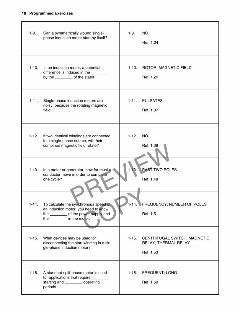
1-9. Can a symmetrically wound single-phase induction motor start by itself?
1-10. In an induction motor, a potential difference is induced in the ________by the ________ of the stator.
1-11. Single-phase induction motors arenoisy, because the rotating magneticfield ________.
1-12. If two identical windings are connectedto a single-phase source, will their combined magnetic field rotate?
1-13. In a motor or generator, how far must aconductor move in order to completeone cycle?
1-14. To calculate the synchronous speed ofan induction motor, you need to knowthe ________ of the power supply andthe ________ in the motor.
1-15. What devices may be used for disconnecting the start winding in a sin-gle-phase induction motor?
1-16. A standard split-phase motor is usedfor applications that require ________starting and ________ operating periods.
1-9. NO
Ref: 1.24
1-10. ROTOR; MAGNETIC FIELD
Ref: 1.29
1-11. PULSATES
Ref: 1.37
1-12. NO
Ref: 1.38
1-13. PAST TWO POLES
Ref: 1.48
1-14. FREQUENCY; NUMBER OF POLES
Ref: 1.51
1-15. CENTRIFUGAL SWITCH, MAGNETICRELAY, THERMAL RELAY
Ref: 1.53
1-16. FREQUENT; LONG
Ref: 1.59
18 Programmed Exercises
PREVIEW
COPY
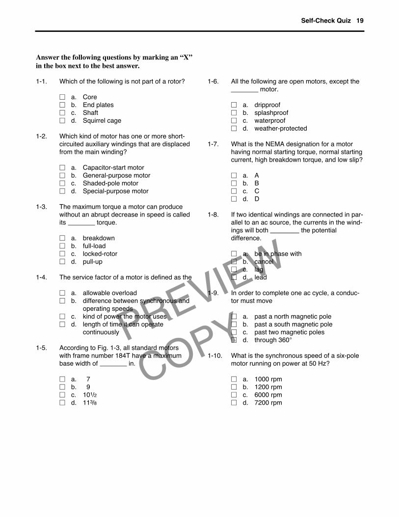
1-1. Which of the following is not part of a rotor?
� a. Core� b. End plates� c. Shaft� d. Squirrel cage
1-2. Which kind of motor has one or more short-circuited auxiliary windings that are displacedfrom the main winding?
� a. Capacitor-start motor� b. General-purpose motor� c. Shaded-pole motor� d. Special-purpose motor
1-3. The maximum torque a motor can producewithout an abrupt decrease in speed is calledits torque.
� a. breakdown� b. full-load� c. locked-rotor� d. pull-up
1-4. The service factor of a motor is defined as the
� a. allowable overload� b. difference between synchronous and
operating speeds� c. kind of power the motor uses� d. length of time it can operate
continuously
1-5. According to Fig. 1-3, all standard motorswith frame number 184T have a maximumbase width of in.
� a. 7� b. 9� c. 101/2� d. 113/8
1-6. All the following are open motors, except themotor.
� a. dripproof� b. splashproof� c. waterproof� d. weather-protected
1-7. What is the NEMA designation for a motorhaving normal starting torque, normal startingcurrent, high breakdown torque, and low slip?
� a. A� b. B� c. C� d. D
1-8. If two identical windings are connected in par-allel to an ac source, the currents in the wind-ings will both ________ the potential difference.
� a. be in phase with� b. cancel� c. lag� d. lead
1-9. In order to complete one ac cycle, a conduc-tor must move
� a. past a north magnetic pole� b. past a south magnetic pole� c. past two magnetic poles� d. through 360°
1-10. What is the synchronous speed of a six-polemotor running on power at 50 Hz?
� a. 1000 rpm� b. 1200 rpm� c. 6000 rpm� d. 7200 rpm
Self-Check Quiz 19
Answer the following questions by marking an “X”in the box next to the best answer.
PREVIEW
COPY
Answers to Self-Check Quiz
1-1. b. End plates. Ref: 1.02
1-2. c. Shaded-pole motor. Ref: 1.06
1-3. a. Breakdown. Ref: 1.07
1-4. a. Allowable overload. Ref: 1.07
1-5. b. 9. Ref: 1.10, Fig. 1-3
1-6. c. Waterproof. Ref: 1.15
1-7. a. A. Ref: 1.18
1-8. c. Lag. Ref: 1.40
1-9. c. Past two magnetic poles. Ref: 1.48
1-10. a. 1000 rpm. Ref: 1.51
Contributions from the following sources are appreciated:
Figure 1-1. Westinghouse Electric Corp.Figure 1-2. Bodine Electric Co.Figure 1-5. Westinghouse Electric Corp.Figure 1-10. A.O. Smith Electrical Products CompanyFigure 1-11. Torq Corporation
Fans, pumps, clocks, and power tools are exam-ples of devices that have single-phase fractional-horsepower motors. Every single-phase motorhas a rotor and a stator. The rotor consists of thecore, the squirrel cage, and the shaft.
The types of single-phase motors you may workwith in the plant include general-purpose, defi-nite-purpose, special-purpose, split-phase, capac-itor-start, capacitor-run, and shaded-pole motors.Motor enclosures are classified as either open ortotally enclosed.
Most motors are manufactured according to stan-dards set by the National Electrical ManufacturersAssociation (NEMA). Standard motors are identi-fied by a frame number—145T, for example. Any
motor with this particular number can be replacedby another motor with the same frame number.
The motor nameplate is an important source ofinformation. It includes such data as the motor’sstyle number, frame size, phase, horsepower,torque and current characteristics, service factor,standard ambient temperature, potential differ-ence of the power supply for the motor, and theclass of insulation used.
Although the pole pieces in an ac induction motorare not readily identifiable, the stator windings arearranged to produce the effect of individual poles.In a motor or generator, a conductor must movepast both a north and a south magnetic pole toaccomplish one complete cycle, which is 360°.
20 Lesson One
SUMMARY