TABLE OF CONTENTS - icemeister.net · TABLE OF CONTENTS Mechanical Temperature Control Gener al...
56
TABLE OF CONTENTS Mechanical Temperature Control General Sequence of Operation 6 Air Sensing Control 8 How to Diagnose 9 Checking the Cut In and Cut Out of the Temperature Control 10 Conditions That Could Cause A Temperature Control Misdiagnosis 10 Changing Out and Installing a Mechanical Temperature Control 10 When to Make an Adjustment to a Mechanical Temperature Control 11 How to Adjust a Mechanical Temperature Control 11 Dixell Electronic Temperature Control General Sequence of Operation 17 Using the Dixell Electronic Control 18 LAE Electronic Temperature Control General Sequence of Operation 22 How to Diagnose an LAE Electronic Control 25 Using the LAE Electronic Control 25 Danfoss Electronic Temperature Control General Sequence of Operation 47 Using the Danfoss Electronic Control 50 MECHANICAL TEMPERATURE CONTROLS 5 ELECTRONIC TEMPERATURE CONTROLS 15
Transcript of TABLE OF CONTENTS - icemeister.net · TABLE OF CONTENTS Mechanical Temperature Control Gener al...

TABLE OF CONTENTS
Mechanical Temperature Control General Sequence of Operation 6
Air Sensing Control 8
How to Diagnose 9
Checking the Cut In and Cut Out of the Temperature Control 10
Conditions That Could Cause A Temperature Control Misdiagnosis 10
Changing Out and Installing a Mechanical Temperature Control 10
When to Make an Adjustment to a Mechanical Temperature Control 11
How to Adjust a Mechanical Temperature Control 11
Dixell Electronic Temperature Control General Sequence of Operation 17
Using the Dixell Electronic Control 18
LAE Electronic Temperature Control General Sequence of Operation 22
How to Diagnose an LAE Electronic Control 25
Using the LAE Electronic Control 25
Danfoss Electronic Temperature Control General Sequence of Operation 47
Using the Danfoss Electronic Control 50
MECHANICAL TEMPERATURE CONTROLS 5
ELECTRONIC TEMPERATURE CONTROLS 15
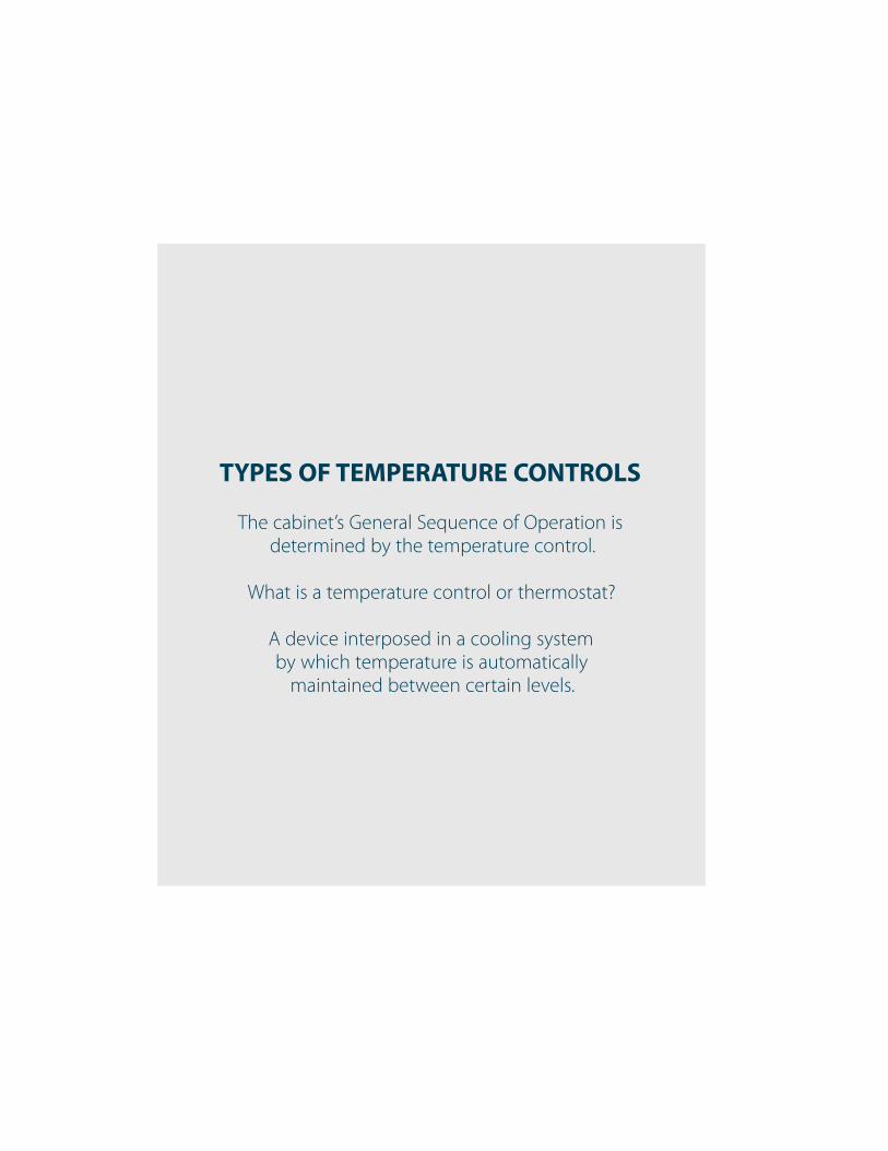
TYPES OF TEMPERATURE CONTROLS
The cabinet’s General Sequence of Operation is
determined by the temperature control.
What is a temperature control or thermostat?
A device interposed in a cooling system
by which temperature is automatically
maintained between certain levels.

MECHANICAL TEMPERATURE CONTROLS
ELECTRONIC CONTROLS CYCLE THE COMPRESSOR BY SENSING AIR TEMPERATURE.
MECHANICAL CONTROLS CYCLE THE COMPRESSOR BY SENSING EITHER AIR TEMPERATURE OR EVAPORATOR COIL TEMPERATURE.
Refrigerator = Evaporator Coil Freezer = Air
ELECTRONIC TEMPERATURE CONTROLS

4
TRUETEMPERATURE CONTROLS SEQUENCE OF OPERATION WWW.TRUEMFG.COM

5
TRUETEMPERATURE CONTROLS SEQUENCE OF OPERATION WWW.TRUEMFG.COM
MECHANICAL TEMPERATURE CONTROLS
MECHANICAL TEMPERATURE CONTROL GENERAL SEQUENCE OF OPERATION
AIR SENSING CONTROL
HOW TO DIAGNOSE
CHECKING THE CUT IN AND CUT OUT OF THE TEMPERATURE CONTROL
CONDITIONS THAT COULD CAUSE A TEMPERATURE CONTROL MISDIAGNOSIS
CHANGING OUT AND INSTALLING A MECHANICAL TEMPERATURE CONTROL
WHEN TO MAKE AN ADJUSTMENT TO A MECHANICAL TEMPERATURE CONTROL
HOW TO ADJUST A MECHANICAL TEMPERATURE CONTROL
6
TRUETEMPERATURE CONTROLS SEQUENCE OF OPERATION WWW.TRUEMFG.COM
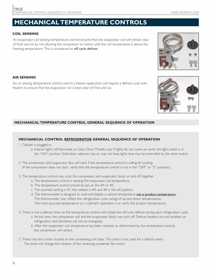
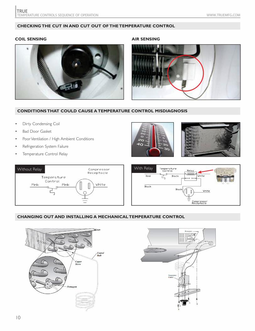
COIL SENSING
AIR SENSING
An evaporator coil sensing temperature control ensures that the evaporator coil will remain clear of frost and ice by not allowing the compressor to restart until the coil temperature is above the freezing temperature. This is considered an off cycle defrost.
An air sensing temperature control used in a freezer application will require a defrost cycle with heaters to ensure that the evaporator coil is kept clear of frost and ice.
1. Cabinet is plugged in. a. Interior lights will illuminate on Glass Door Models only. If lights do not come on verify the light switch is in the “ON” position. Solid door cabinets may or may not have lights that may be controlled by the door switch.
2. The compressor and evaporator fans will start if the temperature control is calling for cooling. (If the compressor does not start, verify that the temperature control is not in the “OFF” or “0” position.)
3. The temperature control may cycle the compressor and evaporator fan(s) on and off together. a. The temperature control is sensing the evaporator coil temperature. b. The temperature control should be set on the #4 or #5. c. The warmest setting is #1, the coldest is #9, and #0 is the off position. d. The thermometer is designed to read and display a cabinet temperature not a product temperature. The thermometer may reflect the refrigeration cycle swings of up and down temperatures. The most accurate temperature on a cabinet's operation is to verify the product temperature.
4. There is not a defrost timer as the temperature control will initiate the off-cycle defrost during each refrigeration cycle. a. At this time, the compressor will and the evaporator fan(s) may turn off. Defrost heaters are not installed on refrigerators and therefore will not be energized. b. After the evaporator coil temperature has been reached, as determined by the temperature control, the compressor will restart.
5. There may be a timer located on the condensing unit base. This timer is not used for a defrost event. The timer will change the rotation of the reversing condenser fan motor.
MECHANICAL CONTROL REFRIGERATOR GENERAL SEQUENCE OF OPERATION
MECHANICAL TEMPERATURE CONTROLS
MECHANICAL TEMPERATURE CONTROL GENERAL SEQUENCE OF OPERATION
7
TRUETEMPERATURE CONTROLS SEQUENCE OF OPERATION WWW.TRUEMFG.COM
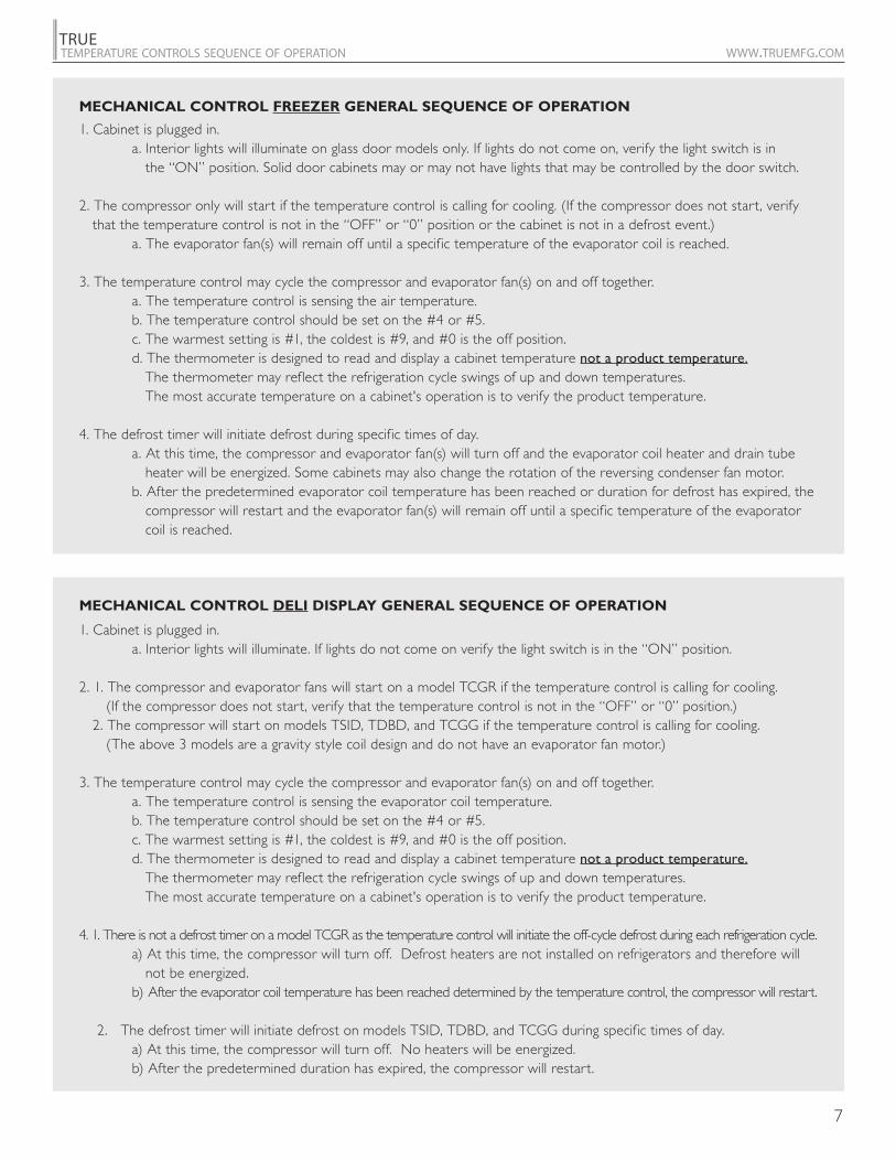
1. Cabinet is plugged in. a. Interior lights will illuminate on glass door models only. If lights do not come on, verify the light switch is in the “ON” position. Solid door cabinets may or may not have lights that may be controlled by the door switch.
2. The compressor only will start if the temperature control is calling for cooling. (If the compressor does not start, verify that the temperature control is not in the “OFF” or “0” position or the cabinet is not in a defrost event.) a. The evaporator fan(s) will remain off until a specific temperature of the evaporator coil is reached.
3. The temperature control may cycle the compressor and evaporator fan(s) on and off together. a. The temperature control is sensing the air temperature. b. The temperature control should be set on the #4 or #5. c. The warmest setting is #1, the coldest is #9, and #0 is the off position. d. The thermometer is designed to read and display a cabinet temperature not a product temperature. The thermometer may reflect the refrigeration cycle swings of up and down temperatures. The most accurate temperature on a cabinet's operation is to verify the product temperature.
4. The defrost timer will initiate defrost during specific times of day. a. At this time, the compressor and evaporator fan(s) will turn off and the evaporator coil heater and drain tube heater will be energized. Some cabinets may also change the rotation of the reversing condenser fan motor. b. After the predetermined evaporator coil temperature has been reached or duration for defrost has expired, the compressor will restart and the evaporator fan(s) will remain off until a specific temperature of the evaporator coil is reached.
1. Cabinet is plugged in. a. Interior lights will illuminate. If lights do not come on verify the light switch is in the “ON” position.
2. 1. The compressor and evaporator fans will start on a model TCGR if the temperature control is calling for cooling. (If the compressor does not start, verify that the temperature control is not in the “OFF” or “0” position.) 2. The compressor will start on models TSID, TDBD, and TCGG if the temperature control is calling for cooling. (The above 3 models are a gravity style coil design and do not have an evaporator fan motor.)
3. The temperature control may cycle the compressor and evaporator fan(s) on and off together. a. The temperature control is sensing the evaporator coil temperature. b. The temperature control should be set on the #4 or #5. c. The warmest setting is #1, the coldest is #9, and #0 is the off position. d. The thermometer is designed to read and display a cabinet temperature not a product temperature. The thermometer may reflect the refrigeration cycle swings of up and down temperatures. The most accurate temperature on a cabinet's operation is to verify the product temperature.
4. 1. There is not a defrost timer on a model TCGR as the temperature control will initiate the off-cycle defrost during each refrigeration cycle. a) At this time, the compressor will turn off. Defrost heaters are not installed on refrigerators and therefore will not be energized. b) After the evaporator coil temperature has been reached determined by the temperature control, the compressor will restart.
2. The defrost timer will initiate defrost on models TSID, TDBD, and TCGG during specific times of day. a) At this time, the compressor will turn off. No heaters will be energized. b) After the predetermined duration has expired, the compressor will restart.
MECHANICAL CONTROL FREEZER GENERAL SEQUENCE OF OPERATION
MECHANICAL CONTROL DELI DISPLAY GENERAL SEQUENCE OF OPERATION
8
TRUETEMPERATURE CONTROLS SEQUENCE OF OPERATION WWW.TRUEMFG.COM
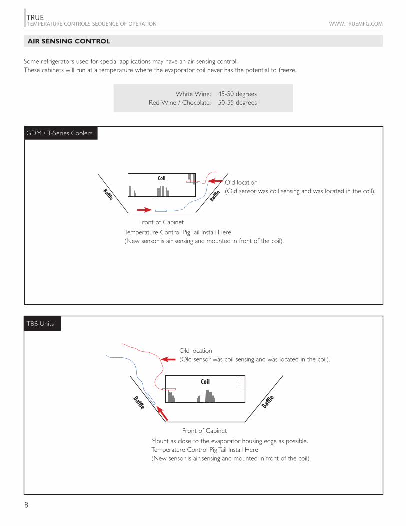
Some refrigerators used for special applications may have an air sensing control. These cabinets will run at a temperature where the evaporator coil never has the potential to freeze.
White Wine: Red Wine / Chocolate:
45-50 degrees50-55 degrees
AIR SENSING CONTROL
GDM / T-Series Coolers
TBB Units
Front of Cabinet
Front of Cabinet
Coil
BaffleBaffl
e
Old location (old sensor was coil sensing and was located in the coil).
Temperature Control Pig Tail Install Here (New sensor is air sensing and mounted in front of the coil).
Coil
BaffleBaffl
e
Old location (old sensor was coil sensing and was located in the coil).
Mount as close to the evaporator housing edge as possible. Temperature Control Pig Tail Install Here (New sensor is air sensing and mounted in front of the coil).
Old location (Old sensor was coil sensing and was located in the coil).
Temperature Control Pig Tail Install Here (New sensor is air sensing and mounted in front of the coil).
Old location (Old sensor was coil sensing and was located in the coil).
Mount as close to the evaporator housing edge as possible.Temperature Control Pig Tail Install Here (New sensor is air sensing and mounted in front of the coil).
9
TRUETEMPERATURE CONTROLS SEQUENCE OF OPERATION WWW.TRUEMFG.COM
HOW TO DIAGNOSE
Confirmed Calibration
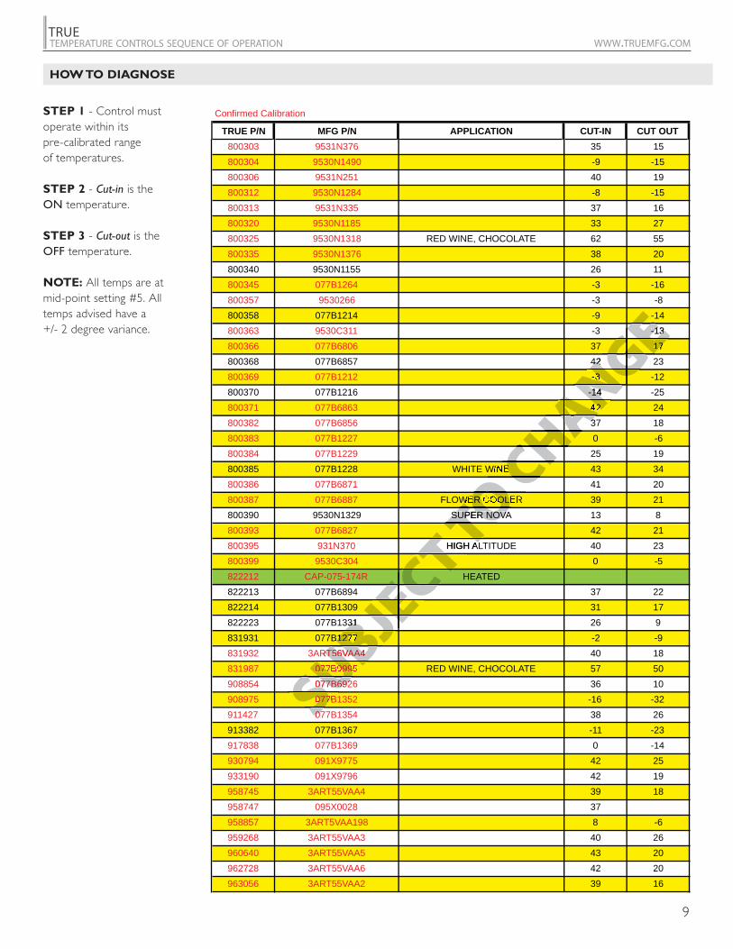
TRUE P/N MFG P/N APPLICATION CUT-IN CUT OUT800303 9531N376 35 15800304 9530N1490 -9 -15800306 9531N251 40 19800312 9530N1284 -8 -15800313 9531N335 37 16800320 9530N1185 33 27800325 9530N1318 RED WINE, CHOCOLATE 62 55800335 9530N1376 38 20800340 9530N1155 26 11800345 077B1264 -3 -16800357 9530266 -3 -8800358 077B1214 -9 -14800363 9530C311 -3 -13800366 077B6806 37 17800368 077B6857 42 23800369 077B1212 -3 -12800370 077B1216 -14 -25800371 077B6863 42 24800382 077B6856 37 18800383 077B1227 0 -6800384 077B1229 25 19800385 077B1228 WHITE WINE 43 34800386 077B6871 41 20800387 077B6887 FLOWER COOLER 39 21800390 9530N1329 SUPER NOVA 13 8800393 077B6827 42 21800395 931N370 HIGH ALTITUDE 40 23800399 9530C304 0 -5822212 CAP-075-174R HEATED822213 077B6894 37 22822214 077B1309 31 17822223 077B1331 26 9831931 077B1277 -2 -9831932 3ART56VAA4 40 18831987 077B0995 RED WINE, CHOCOLATE 57 50908854 077B6926 36 10908975 077B1352 -16 -32911427 077B1354 38 26913382 077B1367 -11 -23917838 077B1369 0 -14930794 091X9775 42 25933190 091X9796 42 19958745 3ART55VAA4 39 18958747 095X0028 37958857 3ART5VAA198 8 -6959268 3ART55VAA3 40 26960640 3ART55VAA5 43 20962728 3ART55VAA6 42 20963056 3ART55VAA2 39 16
STEP 1 - Control must operate within its pre-calibrated range of temperatures. STEP 2 - Cut-in is the ON temperature. STEP 3 - Cut-out is the OFF temperature.
NOTE: All temps are at mid-point setting #5. All temps advised have a +/- 2 degree variance.
SUBJECT TO C
HANGEEGENG
ANCHA
OCH
TO T TO
CT ECT
JEC
BJSUBSU
-13-1317
4242-3
-14-144233
E
ER COOLSUPER NOVASUPER NOVA
HIGH ALA
3131B1277
RT56VAA4RT56VAA4077B099077B692077B6920770707
JEC
HAGEEGEGE
NGNANAHACHCH
OC
OTOTOT TTCT
ECECJEBJ
UBUBSUSUS
10
TRUETEMPERATURE CONTROLS SEQUENCE OF OPERATION WWW.TRUEMFG.COM
CHECKING THE CUT IN AND CUT OUT OF THE TEMPERATURE CONTROL
CONDITIONS THAT COULD CAUSE A TEMPERATURE CONTROL MISDIAGNOSIS
CHANGING OUT AND INSTALLING A MECHANICAL TEMPERATURE CONTROL
COIL SENSING AIR SENSING
With RelayWithout Relay
11
TRUETEMPERATURE CONTROLS SEQUENCE OF OPERATION WWW.TRUEMFG.COM
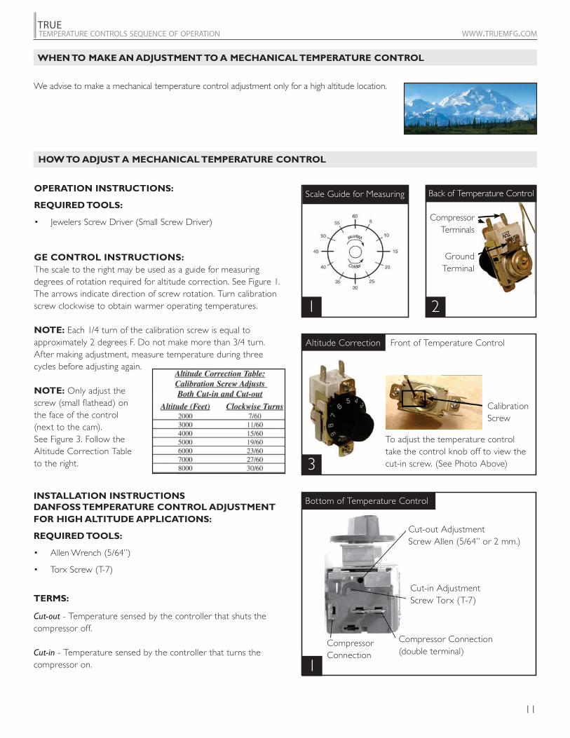
OPERATION INSTRUCTIONS:
REQUIRED TOOLS:
GE CONTROL INSTRUCTIONS:
The scale to the right may be used as a guide for measuring degrees of rotation required for altitude correction. See Figure 1.The arrows indicate direction of screw rotation. Turn calibration screw clockwise to obtain warmer operating temperatures.
NOTE: Each 1/4 turn of the calibration screw is equal to approximately 2 degrees F. Do not make more than 3/4 turn. After making adjustment, measure temperature during three cycles before adjusting again.
NOTE: Only adjust the screw (small flathead) on the face of the control (next to the cam). See Figure 3. Follow the Altitude Correction Table to the right.
WHEN TO MAKE AN ADJUSTMENT TO A MECHANICAL TEMPERATURE CONTROL
Scale Guide for Measuring
We advise to make a mechanical temperature control adjustment only for a high altitude location.
HOW TO ADJUST A MECHANICAL TEMPERATURE CONTROL
Compressor Terminals
GroundTerminal
To adjust the temperature control take the control knob off to view the cut-in screw. (See Photo Above)
Front of Temperature Control
Calibration Screw
Altitude Correction
Back of Temperature Control
1 2
3
1
INSTALLATION INSTRUCTIONS DANFOSS TEMPERATURE CONTROL ADJUSTMENT
FOR HIGH ALTITUDE APPLICATIONS:
REQUIRED TOOLS:
TERMS:
Cut-out - Temperature sensed by the controller that shuts the compressor off.
Cut-in - Temperature sensed by the controller that turns the compressor on.
Cut-out AdjustmentScrew Allen (5/64” or 2 mm.)
Cut-in AdjustmentScrew Torx (T-7)
Compressor Connection (double terminal)
Compressor Connection
Bottom of Temperature Control
12
TRUETEMPERATURE CONTROLS SEQUENCE OF OPERATION WWW.TRUEMFG.COM
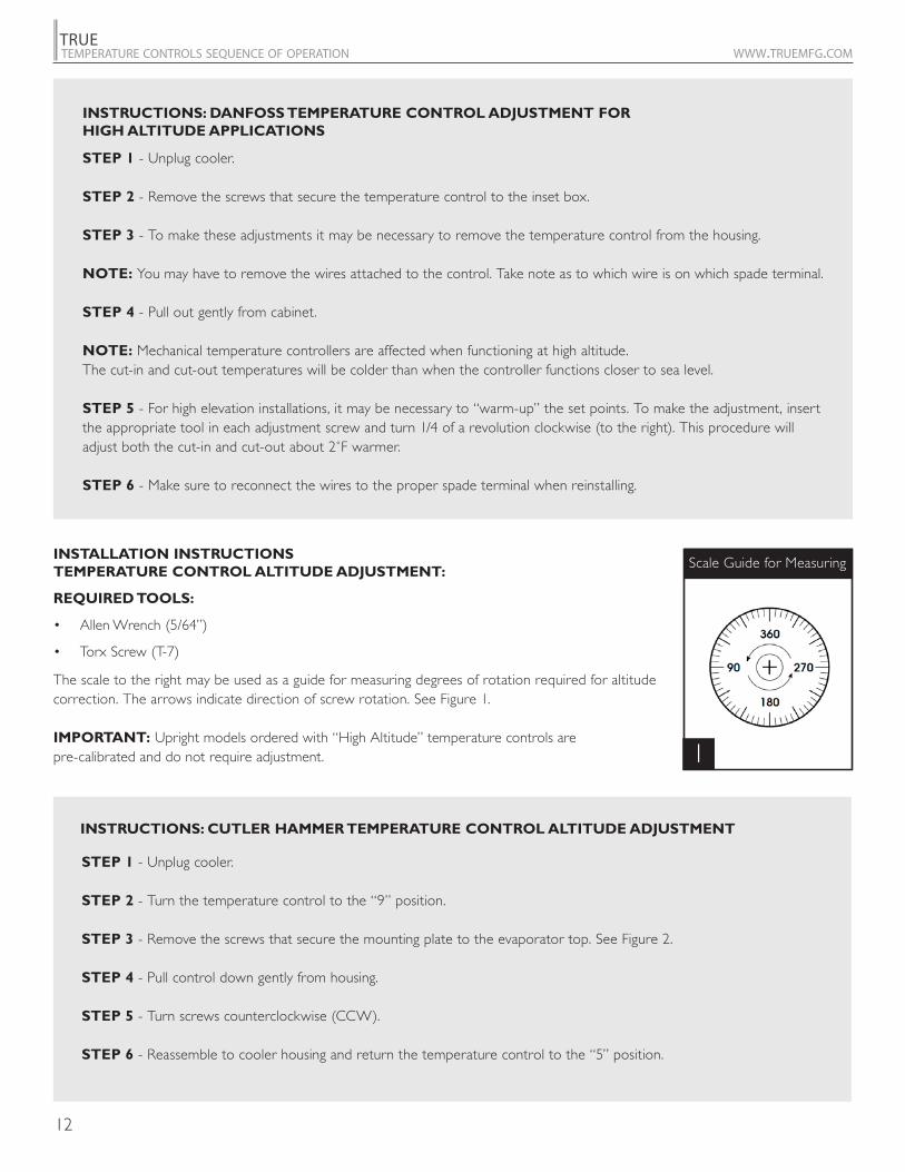
INSTRUCTIONS: DANFOSS TEMPERATURE CONTROL ADJUSTMENT FOR
HIGH ALTITUDE APPLICATIONS
INSTRUCTIONS: CUTLER HAMMER TEMPERATURE CONTROL ALTITUDE ADJUSTMENT
STEP 1 - Unplug cooler.
STEP 2 - Remove the screws that secure the temperature control to the inset box.
STEP 3 - To make these adjustments it may be necessary to remove the temperature control from the housing.
NOTE: You may have to remove the wires attached to the control. Take note as to which wire is on which spade terminal.
STEP 4 - Pull out gently from cabinet.
NOTE: Mechanical temperature controllers are affected when functioning at high altitude. The cut-in and cut-out temperatures will be colder than when the controller functions closer to sea level.
STEP 5 - For high elevation installations, it may be necessary to “warm-up” the set points. To make the adjustment, insert the appropriate tool in each adjustment screw and turn 1/4 of a revolution clockwise (to the right). This procedure will
STEP 6 - Make sure to reconnect the wires to the proper spade terminal when reinstalling.
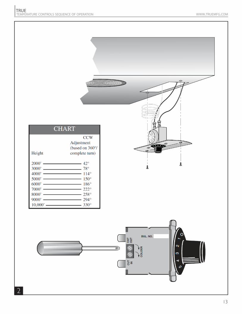
STEP 1 - Unplug cooler.
STEP 2 - Turn the temperature control to the “9” position.
STEP 3 - Remove the screws that secure the mounting plate to the evaporator top. See Figure 2.
STEP 4 - Pull control down gently from housing.
STEP 5 - Turn screws counterclockwise (CCW).
STEP 6 - Reassemble to cooler housing and return the temperature control to the “5” position.
INSTALLATION INSTRUCTIONS TEMPERATURE CONTROL ALTITUDE ADJUSTMENT:
REQUIRED TOOLS:
The scale to the right may be used as a guide for measuring degrees of rotation required for altitude correction. The arrows indicate direction of screw rotation. See Figure 1.
IMPORTANT: Upright models ordered with “High Altitude” temperature controls are pre-calibrated and do not require adjustment.
Scale Guide for Measuring
1
13
TRUETEMPERATURE CONTROLS SEQUENCE OF OPERATION WWW.TRUEMFG.COM
2

14
TRUETEMPERATURE CONTROLS SEQUENCE OF OPERATION WWW.TRUEMFG.COM
15
TRUETEMPERATURE CONTROLS SEQUENCE OF OPERATION WWW.TRUEMFG.COM
ELECTRONIC TEMPERATURE CONTROLS
DIXELL ELECTRONIC TEMPERATURE CONTROL GENERAL SEQUENCE OF OPERATION
USING THE DIXELL ELECTRONIC CONTROL
LAE ELECTRONIC TEMPERATURE CONTROL GENERAL SEQUENCE OF OPERATION
HOW TO DIAGNOSE AN LAE CONTROL
USING THE LAE ELECTRONIC CONTROL
DANFOSS ELECTRONIC TEMPERATURE CONTROL GENERAL SEQUENCE OF OPERATION
HOW TO DIAGNOSE A DANFOSS CONTROL
USING THE DANFOSS ELECTRONIC CONTROL
16
TRUETEMPERATURE CONTROLS SEQUENCE OF OPERATION WWW.TRUEMFG.COM
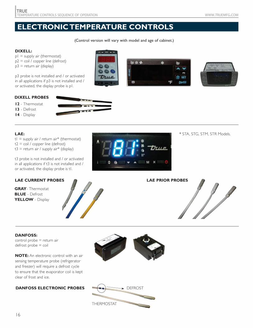
DIXELL:
LAE:
DANFOSS:
NOTE: An electronic control with an air sensing temperature probe (refrigerator and freezer) will require a defrost cycle to ensure that the evaporator coil is kept clear of frost and ice.
ELECTRONIC TEMPERATURE CONTROLS
(Control version will vary with model and age of cabinet.)
12 - Thermostat13 - Defrost14 - Display
GRAY- ThermostatBLUE - DefrostYELLOW - Display
LAE CURRENT PROBES LAE PRIOR PROBES
DIXELL PROBES
DANFOSS ELECTRONIC PROBES
*
17
TRUETEMPERATURE CONTROLS SEQUENCE OF OPERATION WWW.TRUEMFG.COM
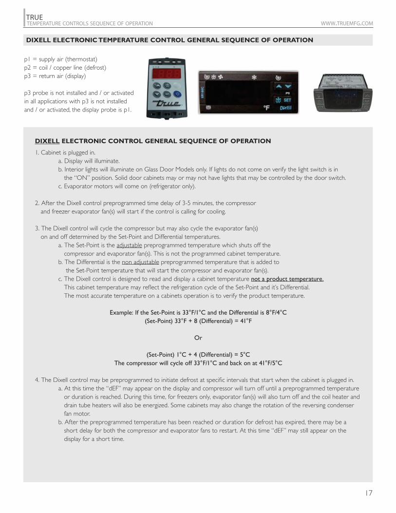
p1 = supply air (thermostat)p2 = coil / copper line (defrost)p3 = return air (display)
p3 probe is not installed and / or activated in all applications with p3 is not installed and / or activated, the display probe is p1.
DIXELL ELECTRONIC TEMPERATURE CONTROL GENERAL SEQUENCE OF OPERATION
DIXELL ELECTRONIC CONTROL GENERAL SEQUENCE OF OPERATION
1. Cabinet is plugged in. a. Display will illuminate. b. Interior lights will illuminate on Glass Door Models only. If lights do not come on verify the light switch is in the “ON” position. Solid door cabinets may or may not have lights that may be controlled by the door switch. c. Evaporator motors will come on (refrigerator only).
2. After the Dixell control preprogrammed time delay of 3-5 minutes, the compressor and freezer evaporator fan(s) will start if the control is calling for cooling.
3. The Dixell control will cycle the compressor but may also cycle the evaporator fan(s) on and off determined by the Set-Point and Differential temperatures. a. The Set-Point is the adjustable preprogrammed temperature which shuts off the compressor and evaporator fan(s). This is not the programmed cabinet temperature. b. The Differential is the non adjustable preprogrammed temperature that is added to the Set-Point temperature that will start the compressor and evaporator fan(s). c. The Dixell control is designed to read and display a cabinet temperature not a product temperature. This cabinet temperature may reflect the refrigeration cycle of the Set-Point and it’s Differential. The most accurate temperature on a cabinets operation is to verify the product temperature.
Example: If the Set-Point is 33°F/1°C and the Differential is 8°F/4°C(Set-Point) 33°F + 8 (Differential) = 41°F
Or
(Set-Point) 1°C + 4 (Differential) = 5°CThe compressor will cycle off 33°F/1°C and back on at 41°F/5°C
4. The Dixell control may be preprogrammed to initiate defrost at specific intervals that start when the cabinet is plugged in. a. At this time the “dEF” may appear on the display and compressor will turn off until a preprogrammed temperature or duration is reached. During this time, for freezers only, evaporator fan(s) will also turn off and the coil heater and drain tube heaters will also be energized. Some cabinets may also change the rotation of the reversing condenser fan motor. b. After the preprogrammed temperature has been reached or duration for defrost has expired, there may be a short delay for both the compressor and evaporator fans to restart. At this time “dEF” may still appear on the display for a short time.
18
TRUETEMPERATURE CONTROLS SEQUENCE OF OPERATION WWW.TRUEMFG.COM
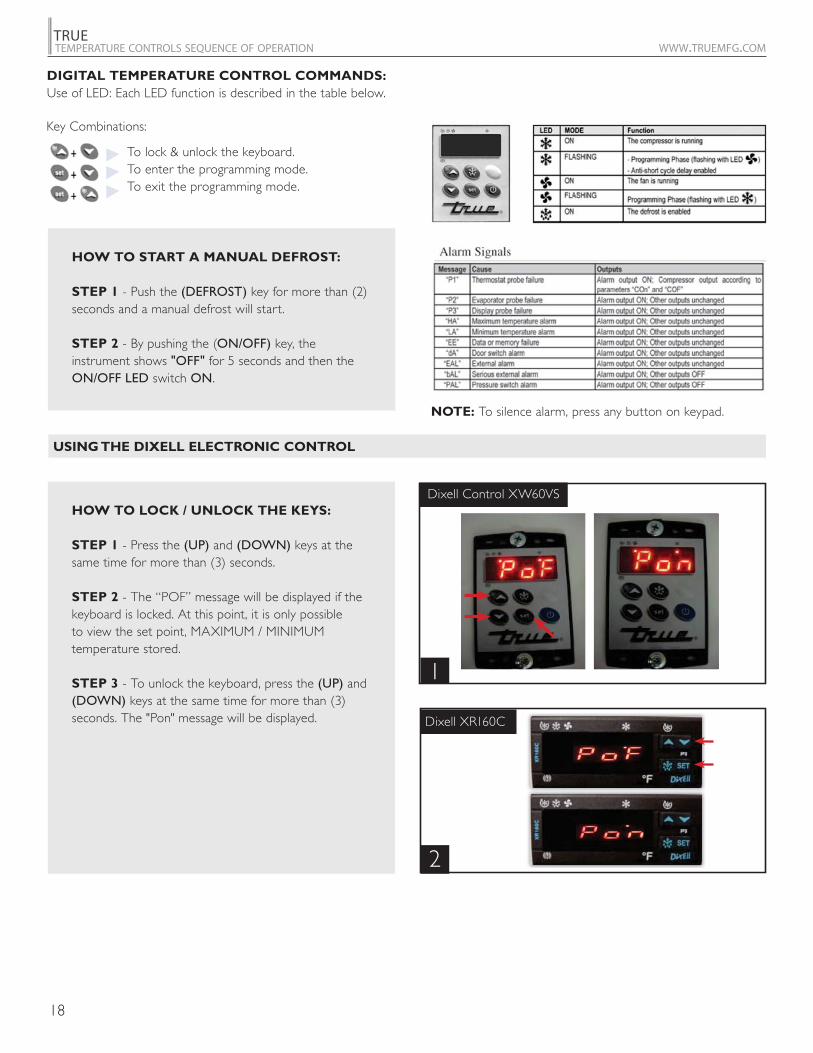
Dixell Control XW60VS
Dixell XR160C
USING THE DIXELL ELECTRONIC CONTROL
HOW TO LOCK / UNLOCK THE KEYS:
STEP 1 - Press the (UP) and (DOWN) keys at the same time for more than (3) seconds.
STEP 2 - The “POF” message will be displayed if the keyboard is locked. At this point, it is only possible to view the set point, MAXIMUM / MINIMUM temperature stored.
STEP 3 - To unlock the keyboard, press the (UP) and (DOWN) keys at the same time for more than (3) seconds. The "Pon" message will be displayed.
HOW TO START A MANUAL DEFROST:
STEP 1 - Push the (DEFROST) key for more than (2) seconds and a manual defrost will start.
STEP 2 - By pushing the (ON/OFF) key, the instrument shows "OFF" for 5 seconds and then the ON/OFF LED switch ON.
1
2
DIGITAL TEMPERATURE CONTROL COMMANDS:
Use of LED: Each LED function is described in the table below.
To lock & unlock the keyboard.To enter the programming mode.To exit the programming mode.
Key Combinations:
NOTE: To silence alarm, press any button on keypad.

19
TRUETEMPERATURE CONTROLS SEQUENCE OF OPERATION WWW.TRUEMFG.COM
THE SET POINT IS WHERE THE COMPRESSOR
WILL SHUT OFF.
THE LOCAL DISPLAY SHOWS WHICH
PROBE IS READING.
Dixell Control XW60VS
Dixell Control XW60VS
Dixell XR160C
HOW TO SEE AND MODIFY THE SET POINT:
STEP 1 - Model XW60VS push and immediately release the (SET) key. Model XR160C push and hold the (SET) key: The display will show the (SET) point value.
STEP 2 - The (SET LED) will start blinking.
STEP 3 - To change the (SET) value, push the (UP) or (DOWN) arrows within (10) seconds.
STEP 4 - To memorize the new set point value, push the (SET) key again or wait (10) seconds.
HOW TO SEE “LOD” LOCAL DISPLAY:
STEP 1 - Press and hold the (SET) and (DOWN) arrows at the same time for (7-12) seconds.
STEP 2 - You should then see (HY).
STEP 3 - Release the keys.
STEP 4 - Press the down arrow until you see the letters (LOD).
STEP 5 - Press the (SET) button. You should see P1, P2, P3. This is the probe used for the display. (All probes may not be used in some applications). To change, press the (UP / DOWN) arrow to set a new number and then push the (SET) button to save these changes.
Wait 10 seconds for control to display temperature.
1
1
2
Dixell XR160C
2

20
TRUETEMPERATURE CONTROLS SEQUENCE OF OPERATION WWW.TRUEMFG.COM
THE INTERVAL BETWEEN DEFROST
TERMINATION IS THE TIME BETWEEN
EACH DEFROST CYCLE.
NOTE: This interval is started when the cabinet is plugged in or after initiate of manual defrost.
THE PROGRAM PARAMETERS CAN BE
DOWNLOADED BY THE USE OF A "HOT KEY."
NOTE: These parameters will vary from model to model.
Dixell Control XW60VS
Dixell Control XW60VS
1
1
Dixell XR160C
2
HOW TO SEE “idF” INTERVAL
BETWEEN DEFROST:
STEP 1 - Press and hold the (SET) and (DOWN) arrows at the same time for (7-12) seconds.
STEP 2 - You should then see (HY).
STEP 3 - Release the keys. STEP 4 - Press the down arrow until you see the letters "idF". STEP 5 - Press the (SET) button. You should see the number 6. This is time in hours between each defrost cycle. To change, press the (UP / DOWN) arrow to set a new number and then push the (SET) button to save these changes. Wait 10 seconds for control to display temperature.
NOTE: The interval between defrost termination is the time between each defrost cycle.
HOW TO DOWNLOAD
THE CONTROL PARAMETER:
STEP 1 - Turn controller in the off position or unplug cabinet.
STEP 2 - Insert “Hot Key” into the back of the controller.
STEP 3 - Turn on controller or plug in cabinet. STEP 4 - "Hot Key" will download automatically once download is complete. Remove “Hot Key”.
21
TRUETEMPERATURE CONTROLS SEQUENCE OF OPERATION WWW.TRUEMFG.COM
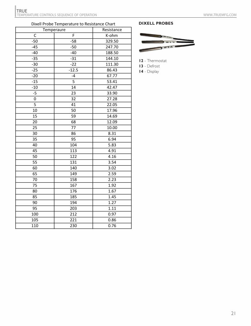
12 - Thermostat13 - Defrost14 - Display
DIXELL PROBES

22
TRUETEMPERATURE CONTROLS SEQUENCE OF OPERATION WWW.TRUEMFG.COM
t1 = supply air / return air* (thermostat)t2 = coil / copper line (defrost) t3 = return air / supply air* (display) t3 probe is not installed and / or activated in all applicationswith t3 is not installed and / or activated, the display probe is t1.
LAE ELECTRONIC CONTROL GENERAL SEQUENCE OF OPERATION
LAE ELECTRONIC TEMPERATURE CONTROL GENERAL SEQUENCE OF OPERATION
1. Cabinet is plugged in. a. Display will illuminate. b. Interior light will illuminate on Glass Door Models only. Solid door cabinet lights are controlled by the door switch.
2. After the LAE control preprogrammed time delay of up to 6 minutes, the compressor and evaporator fan(s) will start if the control is calling for cooling. a. Control may be already pre-programmed from the factory so at the start of every compressor cycle or during a defrost cycle, the condenser fan(s) will reverse for 30 seconds to blow dirt off the condensing coil.
3. The LAE control will cycle the compressor but may also cycle evaporator fan(s) on and off determined by the Set-Point and Differential temperatures. a. The Set-Point is the adjustable preprogrammed temperature which shuts off the compressor and evaporator fan(s). This is not the programmed cabinet temperature. b. The Differential is the non adjustable preprogrammed temperature that is added to the Set-Point temperature that will restart the compressor and evaporator fan(s). c. The LAE control is designed to read and display a cabinet temperature not a product temperature. This cabinet temperature may reflect the refrigeration cycle of the Set-Point and it’s Differential. The most accurate temperature on a cabinets operation is to verify the product temperature.
Example: If the Set-Point is -9°F/-23°C and the Differential is 10°F/5°C(Set-Point) -9°F + 10 (Differential) = 1°F
Or
(Set-Point) -23°C + 5 (Differential) = -18°C The compressor and evaporator fan(s) will cycle off -9°F/-23°C and back on at 1°F/-18°C
4. The LAE control may be preprogrammed to initiate defrost by interval or at specific times of day. a. At this time the “dEF” will appear on the display and compressor will turn off until a preprogrammed temperature or duration is reached. During this time for freezers only, evaporator fan(s) will also turn off and the coil heater and drain tube heaters will also be energized. Some cabinets may also change the rotation of the reversing condenser fan motor. b. After the preprogrammed temperature or duration for defrost has been reached there may be a short delay for both the compressor and evaporator fans to restart. At this time “dEF” may still appear on the display for a short time.
*

23
TRUETEMPERATURE CONTROLS SEQUENCE OF OPERATION WWW.TRUEMFG.COM
LAE MODEL TMW ELECTRONIC CONTROL GENERAL SEQUENCE OF OPERATION
1. Cabinet is plugged in. a. Display will illuminate.
2. After the LAE control preprogrammed time delay of up to 6 minutes, the compressor will start if the control is calling for cooling. a. Control may be already preprogrammed from the factory so at the start of every compressor cycle, the condenser fan(s) will reverse for 30 seconds to blow dirt off the condensing coil.
3. The LAE control will cycle the compressor on and off determined by the Set-Point and Differential temperatures. a. The Set-Point is the adjustable preprogrammed temperature which shuts off the compressor and evaporator fan(s). This is not the programmed cabinet temperature. b. The Differential is the non adjustable preprogrammed temperature that is added to the Set-Point temperature that will restart the compressor and evaporator fan(s). c. The LAE control is designed to read and display a cabinet temperature not a product temperature. This cabinet temperature may reflect the refrigeration cycle of the Set-Point and it’s Differential. The most accurate temperature on a cabinets operation is to verify the product temperature.
Example: If the Set-Point is -9°F/-23°C and the Differential is 10°F/5°C(Set-Point) -9°F + 10 (Differential) = 1°F
Or
(Set-Point) -23°C + 5 (Differential) = -18°CThe compressor will cycle off -9°F/-23°C and back on at 1°F/-18°C
4. The LAE control is not and cannot be preprogrammed to initiate defrost, only refrigeration. a. The cabinet will need to be manually defrosted. Unplug the cabinet or turn the LAE control to “OFF" per LAE instruction sheet. The manual defrost frequency will depend on the units usage, environment, and the amount of frost.

24
TRUETEMPERATURE CONTROLS SEQUENCE OF OPERATION WWW.TRUEMFG.COM
LAE MODEL HEATED CABINET ELECTRONIC CONTROL GENERAL SEQUENCE OF OPERATION
1. Cabinet is plugged in. a. Display will illuminate.
2. The LAE control will energize the heat elements if the control is calling for heat.
3. The LAE control will cycle the heating elements on and off determined by the Set-Point and Differential temperatures. a. The Set-Point is the adjustable preprogrammed temperature which de-energizes the heat elements. This is not the programmed cabinet temperature. b. The Differential is the non adjustable preprogrammed temperature that is added to the Set-Point temperature that will re-energize the heat elements. c. The LAE control is designed to read and display a cabinet temperature not a product temperature. This cabinet temperature may reflect the heating cycle of the Set-Point and it’s Differential. The most accurate temperature on a cabinets operation is to verify the product temperature.
Example: If the Set-Point is 180°F/82.2°C and the Differential is 1°F/.56°C(Set-Point) 180°F + 1 (Differential) = 181°F
Or
(Set-Point) 82.2°C + .56 (Differential) = 82.76°CThe heating elements will cycle on 180°F/82.2°C and back off at 181°F/82.76°C
25
TRUETEMPERATURE CONTROLS SEQUENCE OF OPERATION WWW.TRUEMFG.COM
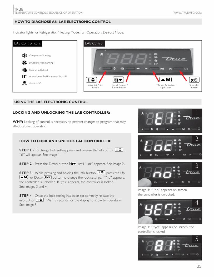
HOW TO LOCK AND UNLOCK LAE CONTROLLER:
STEP 1 - To change lock setting press and release the Info button . “t1” will appear. See image 1.
STEP 2 - Press the Down button until “Loc” appears. See image 2. STEP 3 - While pressing and holding the Info button press the Up or Down button to change the lock settings. If “no” appears, the controller is unlocked. If “yes” appears, the controller is locked. See images 3 and 4.
STEP 4 - Once the lock setting has been set correctly release the info button . Wait 5 seconds for the display to show temperature. See image 5.
LOCKING AND UNLOCKING THE LAE CONTROLLER:
WHY: Locking of control is necessary to prevent changes to program that may affect cabinet operation.
1
2
5
3
Image 3: If “no” appears on screen, the controller is unlocked.
4
Image 4: If “yes” appears on screen, the controller is locked.
HOW TO DIAGNOSE AN LAE ELECTRONIC CONTROL
USING THE LAE ELECTRONIC CONTROL
Indicator lights for Refrigeration/Heating Mode, Fan Operation, Defrost Mode.
Info / Set PointButton
Manual Defrost / Down Button
Manual Activation Up Button
Stand-ByButton
LAE Control
Compressor Running
Activation of 2nd Parameter Set - NA
Alarm - NA
Cabinet in Defrost
Evaporator Fan Running
LAE Control Icons
26
TRUETEMPERATURE CONTROLS SEQUENCE OF OPERATION WWW.TRUEMFG.COM
ON Position
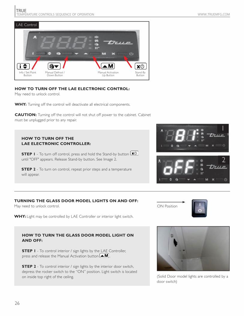
HOW TO TURN THE GLASS DOOR MODEL LIGHT ON
AND OFF:
STEP 1 - To control interior / sign lights by the LAE Controller,press and release the Manual Activation button .
STEP 2 - To control interior / sign lights by the interior door switch, depress the rocker switch to the “ON” position. Light switch is located on inside top right of the ceiling. (Solid Door model lights are controlled by a
door switch)
TURNING THE GLASS DOOR MODEL LIGHTS ON AND OFF:
May need to unlock control.
WHY: Light may be controlled by LAE Controller or interior light switch.
HOW TO TURN OFF THE LAE ELECTRONIC CONTROL:
May need to unlock control.
WHY: Turning off the control will deactivate all electrical components.
CAUTION: Turning off the control will not shut off power to the cabinet. Cabinet must be unplugged prior to any repair.
HOW TO TURN OFF THE
LAE ELECTRONIC CONTROLLER:
STEP 1 - To turn off control, press and hold the Stand-by button until "OFF" appears. Release Stand-by button. See Image 2.
STEP 2 - To turn on control, repeat prior steps and a temperaturewill appear.
1
2
Info / Set PointButton
Manual Defrost / Down Button
Manual Activation Up Button
Stand-ByButton
LAE Control
27
TRUETEMPERATURE CONTROLS SEQUENCE OF OPERATION WWW.TRUEMFG.COM
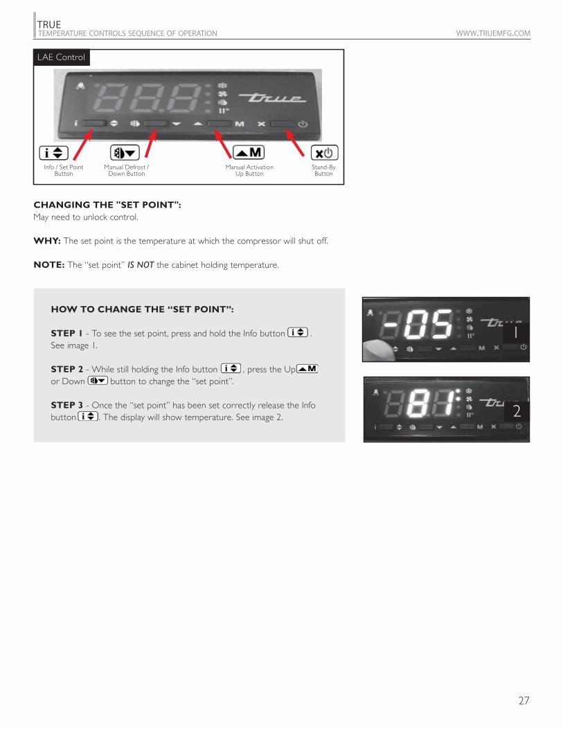
HOW TO CHANGE THE “SET POINT”:
STEP 1 - To see the set point, press and hold the Info button . See image 1. STEP 2 - While still holding the Info button , press the Up or Down button to change the “set point”.
STEP 3 - Once the “set point” has been set correctly release the Info button . The display will show temperature. See image 2.
1
2
CHANGING THE "SET POINT":
May need to unlock control.
WHY: The set point is the temperature at which the compressor will shut off.
NOTE: The “set point” IS NOT the cabinet holding temperature.
Info / Set PointButton
Manual Defrost / Down Button
Manual Activation Up Button
Stand-ByButton
LAE Control

28
TRUETEMPERATURE CONTROLS SEQUENCE OF OPERATION WWW.TRUEMFG.COM
HOW TO INITIATE A MANUAL DEFROST:
The method to initiate a manual defrost is determined by the Defrost Mode Parameter “DTM” preprogrammed in the controller.
REGULAR TIME DEFROST (TIM)
If controller is preprogrammed for “TIM”, press and release the Manual Defrost button until “dEF” appears.
REAL TIME CLOCK (RTC)
If controller is preprogrammed for “RTC” press the and hold the Manual Defrost button for 5 seconds until “dh1” appears. Release the Manual Defrost button and then press and hold for an additional 5 seconds until “dEF” appears.
NOTE: Defrost will only terminate once a specific preset temperature or a preset time duration is reached.
INITIATE A MANUAL DEFROST:
May need to unlock control.
WHY: A one time additional defrost may be necessary to clear accumulated frost / ice from evaporator coil.
Info / Set PointButton
Manual Defrost / Down Button
Manual Activation Up Button
Stand-ByButton
LAE Control

29
TRUETEMPERATURE CONTROLS SEQUENCE OF OPERATION WWW.TRUEMFG.COM
HOW TO CHANGE “DEFROST INTERVALS":
STEP 1 - To see the set point, press and hold the Info button and the Stand-by button at the same time. “ScL” will appear. See image 1. NOTE: If using BIT25 controller “SPL” will appear. See image 2.
STEP 2 - Push the Up button until “dFt” appears. See image 3.
STEP 3 - Press and hold the Info button to see the defrost interval time. See image 4
STEP 4 - While pressing and holding the Info button , press the Up or Down button to change the defrost interval times (higher the number the less frequent the cabinet will defrost).
STEP 5 - Once the defrost interval time has been changed, release the Info button .
STEP 6 - Wait 30 seconds for the display to show temperature. See image 5.
1
3
4
2
5
p
CHANGING "DEFROST INTERVALS":
May need to unlock control. This can only be changed if defrost mode parameter “DFM” is set for “TIM”.
WHY: The defrost interval is the time duration between defrost cycles. The defrost interval time starts when the cabinet is supplied power or after a manual defrost.
Info / Set PointButton
Manual Defrost / Down Button
Manual Activation Up Button
Stand-ByButton
LAE Control
30
TRUETEMPERATURE CONTROLS SEQUENCE OF OPERATION WWW.TRUEMFG.COM
1
3
4
2
5
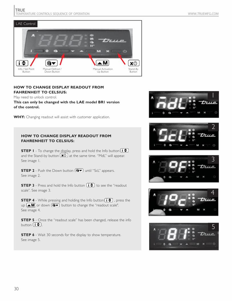
HOW TO CHANGE DISPLAY READOUT FROM
FAHRENHEIT TO CELSIUS:
May need to unlock control. This can only be changed with the LAE model BR1 version
of the control.
WHY: Changing readout will assist with customer application.
HOW TO CHANGE DISPLAY READOUT FROM
FAHRENHEIT TO CELSIUS:
STEP 1 - To change the display, press and hold the Info button and the Stand-by button at the same time. “MdL” will appear. See image 1.
STEP 2 - Push the Down button until “ScL” appears. See image 2.
STEP 3 - Press and hold the Info button to see the “readout scale”. See image 3.
STEP 4 - While pressing and holding the Info button , press the up or down button to change the “readout scale".See image 4.
STEP 5 - Once the “readout scale” has been changed, release the info button .
STEP 6 - Wait 30 seconds for the display to show temperature. See image 5.
p
Info / Set PointButton
Manual Defrost / Down Button
Manual Activation Up Button
Stand-ByButton
LAE Control
31
TRUETEMPERATURE CONTROLS SEQUENCE OF OPERATION WWW.TRUEMFG.COM
1
2
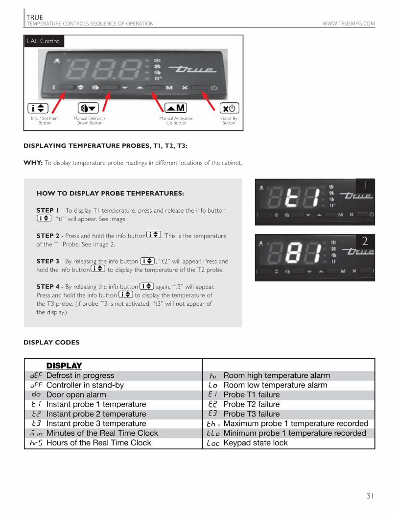
DISPLAYING TEMPERATURE PROBES, T1, T2, T3:
WHY: To display temperature probe readings in different locations of the cabinet.
DISPLAY CODES
HOW TO DISPLAY PROBE TEMPERATURES:
STEP 1 - To display T1 temperature, press and release the info button . “t1” will appear. See image 1.
STEP 2 - Press and hold the info button . This is the temperature of the T1 Probe. See image 2.
STEP 3 - By releasing the info button , “t2” will appear. Press and hold the info button to display the temperature of the T2 probe.
STEP 4 - By releasing the info button again, “t3” will appear. Press and hold the info button to display the temperature of the T3 probe. (If probe T3 is not activated, “t3” will not appear of the display.)
Info / Set PointButton
Manual Defrost / Down Button
Manual Activation Up Button
Stand-ByButton
LAE Control
32
TRUETEMPERATURE CONTROLS SEQUENCE OF OPERATION WWW.TRUEMFG.COM
SPL (X-32) / 1.8 ADOSPH (X-32) / 1.8 AHMSP (X-32) / 1.8 AHT (X-32) / 1.8
HYS (X) / 1.8 ACCExample: CRT IISM
CT1 IISL (X-32) / 1.8CT2 IISH (X-32) / 1.8CSD IISP (X-32) / 1.8DFM IIHY (X) / 1.8DFT IIFCDFB IIDFDLI (X-32) / 1.8 SBDTO DI1DTY DI2
SCL 1C ADO DPD T3MSPL (X-32) / 1.8 AHM DRN OS3 (X) / 1.8SPH (X-32) / 1.8 AHT (X-32) / 1.8 DDM PSL (X-32) / 1.8SP (X-32) / 1.8 ACC DDY PSR (X-32) / 1.8C-H IISM FID POFHYS (X) / 1.8 IISL (X-32) / 1.8 FDD (X-32) / 1.8 LSMCRT IISH (X-32) / 1.8 FTO OA1CT1 IISP (X-32) / 1.8 FCM OA2CT2 IIHY (X) / 1.8 FDT (X) / 1.8 OS1 (X) / 1.8CSD IIFC FDH (X) / 1.8 T2DFM HDS FT1 OS2 (X) / 1.8DFT IIDF FT2 TLDDH1 SB FT3 SCL 1CDH2 DS ATM SIMDH3 DSM ALA (X-32) / 1.8 ADRDH4 DI2 AHA (X-32) / 1.8DH5 STT ALR (X) / 1.8DH6 EDT AHR (X) / 1.8DLI (X-32) / 1.8 LSM ATIDTO OA1 ATDDTY OA2DPD CD SPL (X-32) / 1.8 ADODRN INP SPH (X-32) / 1.8 SBDDM OS1 (X) / 1.8 SP (X-32) / 1.8 DI1DDY T2 CM DI2FID OS2 (X) / 1.8 HYS (X) / 1.8 PSL (X-32) / 1.8FDD (X-32) / 1.8 T3 TON PSR (X-32) / 1.8FTO OS3 (X) / 1.8 TOF POFFCM TLD PB DSMFDT (X) / 1.8 TDS IT LSMFDH (X) / 1.8 AVG DT OA1FT1 SIM AR OA2FT2 ADR CT OS1 (X) / 1.8FT3 PF TLDATM HSD SCL 1CALA (X-32) / 1.8 ATM SIMAHA (X-32) / 1.8 ALA (X-32) / 1.8 ADRALR (X) / 1.8 AHA (X-32) / 1.8AHR (X) / 1.8 ALR (X) / 1.8ATI AHR (X) / 1.8ATD ATD
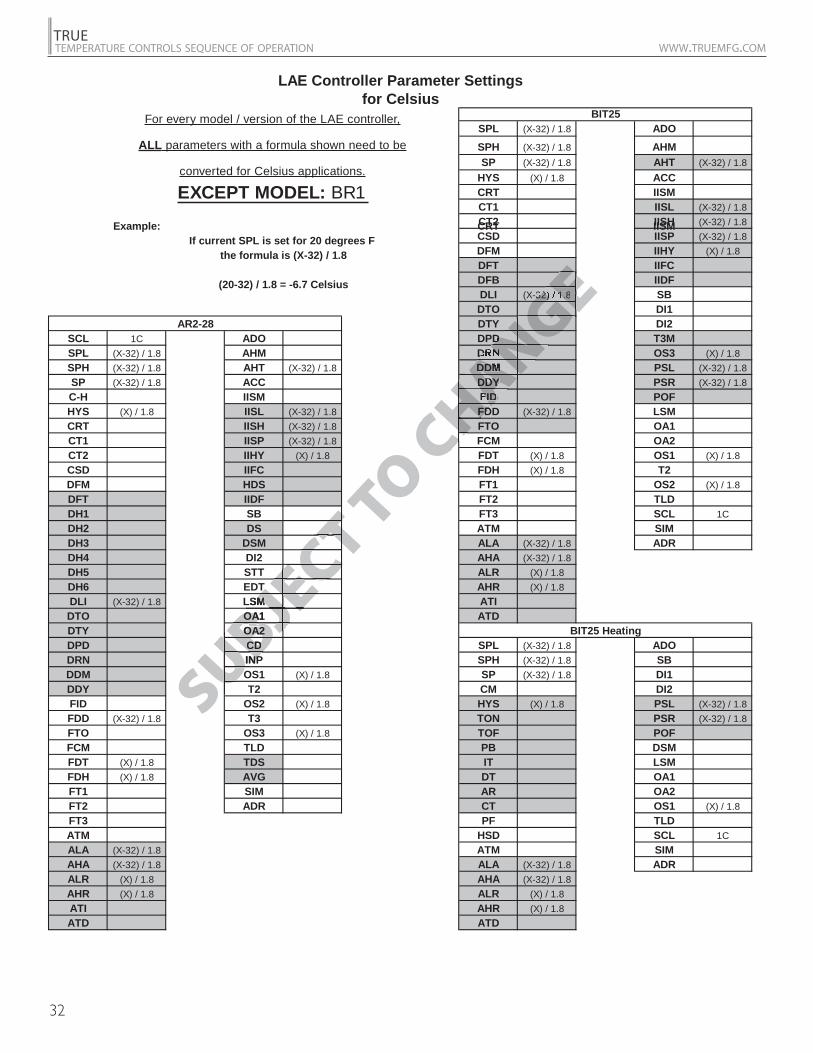
for CelsiusLAE Controller Parameter Settings
(20-32) / 1.8 = -6.7 Celsius
BIT25
BIT25 Heating
All parameters with a formula shown need to beconverted for Celsius applications.
If current SPL is set for 20 degrees F the formula is (X-32) / 1.8
For every model / version of the LAE controller,
AR2-28
SUBJE
TTLSMMOA1OAOA2OA2CDCDINPNPOO
EJEBJEBJUBUBUUU
JECT TO C
HANGEENNGE
HANNG
CHACHCH
-32) / 1.8
DN
DDMDDYFIDFD
EEGEGNGNGANAN
HAHACHCH
TTCTECEC
JEJEJ
ANE
CH
CTJE
EXCEPT MODEL: BR1
Example: CRT IISM
(20-32) / 1.8 = -6.7 Celsius
If current SPL is set for 20 degrees F the formula is (X-32) / 1.8
For every model / version of the LAE controller,
ALL parameters with a formula shown need to be
converted for Celsius applications.

33
TRUETEMPERATURE CONTROLS SEQUENCE OF OPERATION WWW.TRUEMFG.COM
MODEL:MODEL:
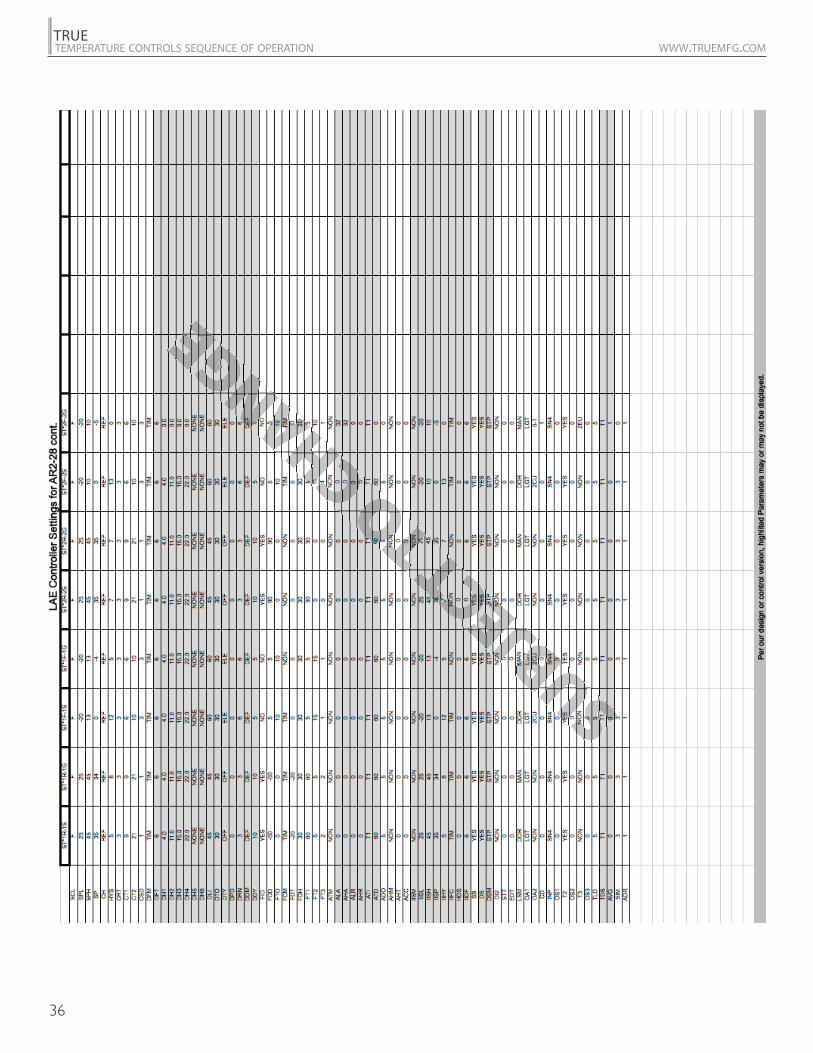
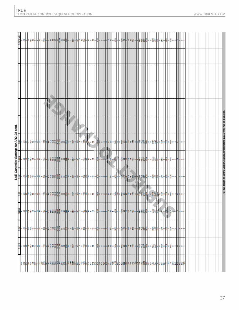
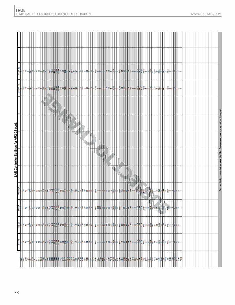
SCLSPLSPHSPC-HHYSCRTCT1CT2CSDDFMDFTDH1DH2DH3DH4DH5DH6DLIDTODTYDPDDRNDDMDDYFIDFDDFTOFCMFDTFDHFT1FT2FT3ATMALAAHAALRAHRATIATD
ADOAHMAHTACCIISMIISLIISHIISPIIHYIIFCHDSIIDFSBDSDSMDI2STTEDTLSMOA1OA2CDINPOS1T2
OS2T3
OS3TLDTDSAVGSIMADR
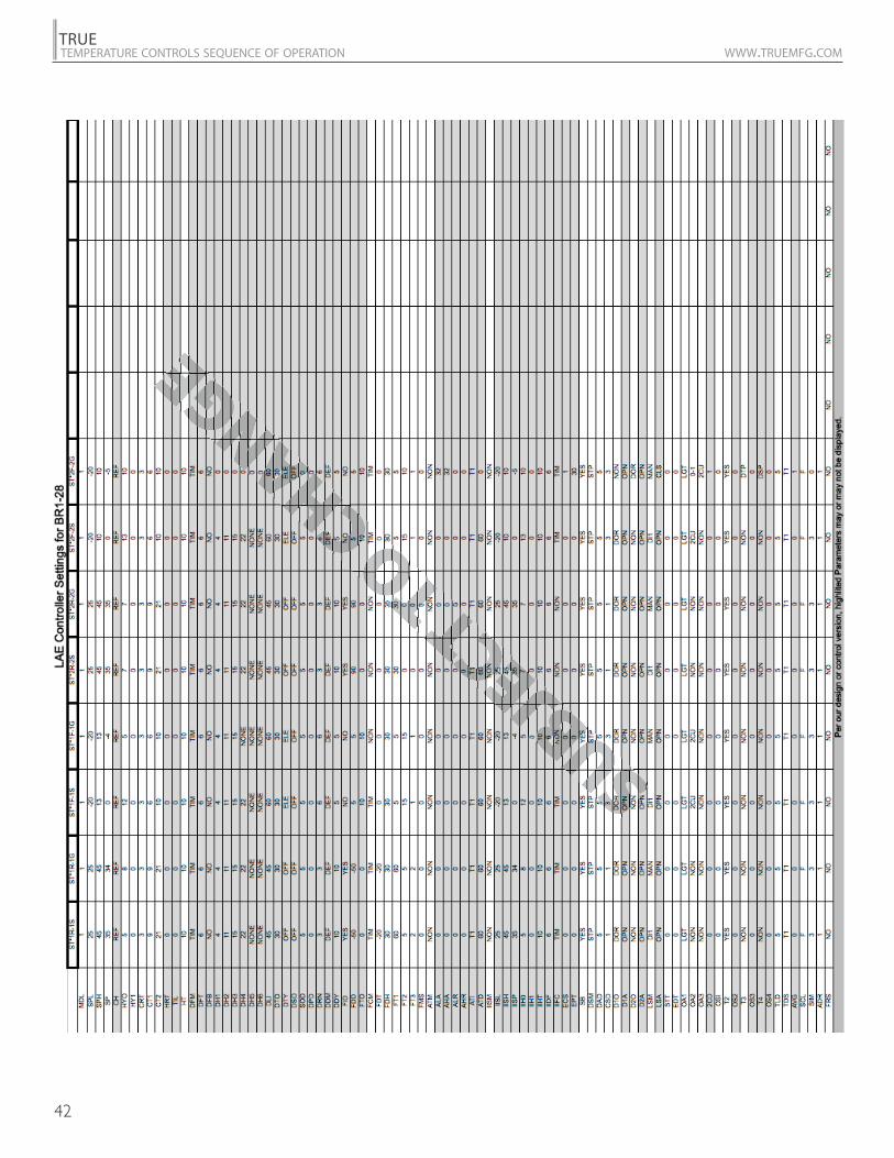
LAE CONTROLLER SETTING
AR2-28
LAE CONTROLLER SETTING
BIT25
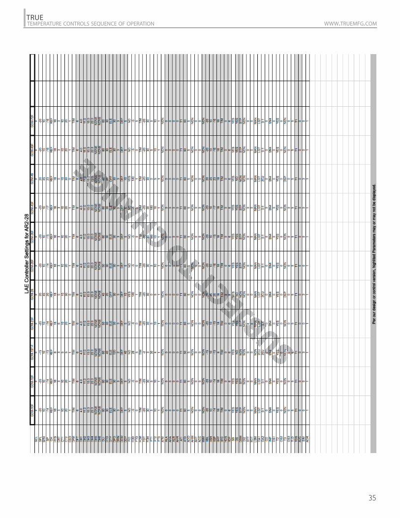
Per our design or control version, highlighted Parameters may or may not be displayed.
Parameters list settings are subject to change without prior notification.
Model specific parameters settings are on separate pages.
SPLSPHSP
HYSCRTCT1CT2CSDDFMDFTDFBDLIDTODTYDPDDRNDDMDDYFIDFDDFTOFCMFDTFDHFT1FT2FT3ATMALAAHAALRAHRATIATD
ADOAHMAHTACCIISMIISLIISHIISPIIHYIIFCIIDFSBDI1DI2T3MOS3PSLPSRPOFLSMOA1OA2OS1T2
OS2TLDSCLSIMADR
SSSSSSSSSJBJMM JBJ
UBJJBJJBJ
O CHANG
O
GENGENG
CCSDCSDDFMDFMDFTDF
EEGEGENGNGNGNGNGGGNGNGNG
34
TRUETEMPERATURE CONTROLS SEQUENCE OF OPERATION WWW.TRUEMFG.COM
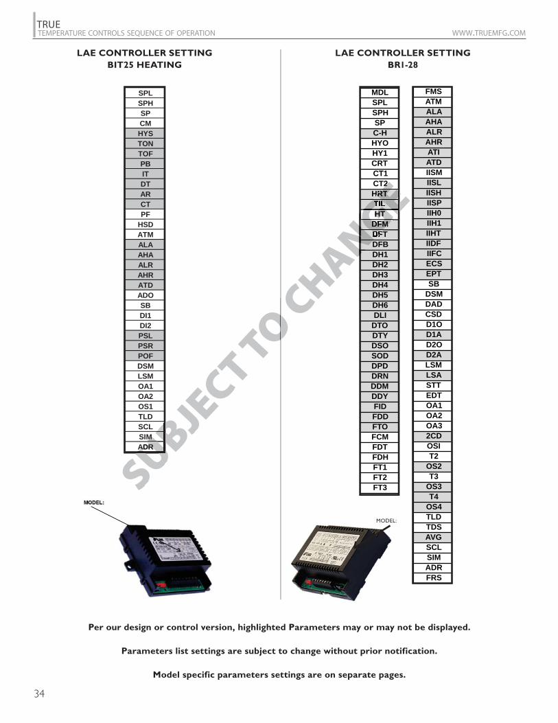
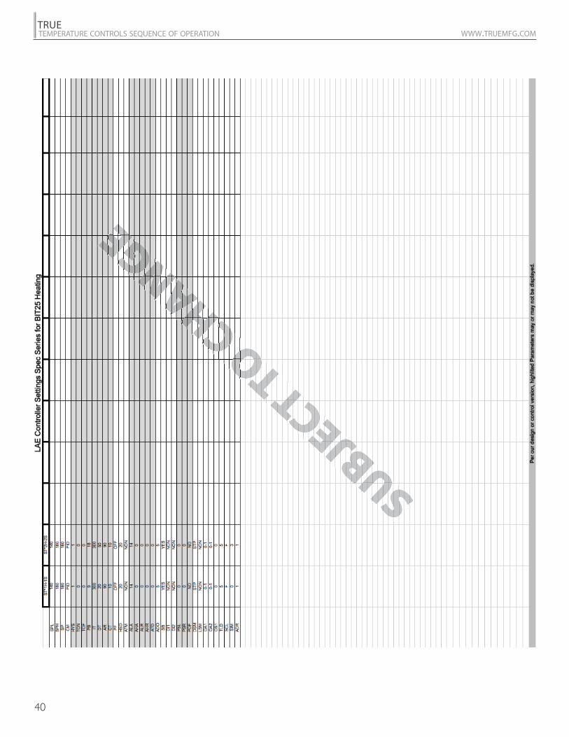
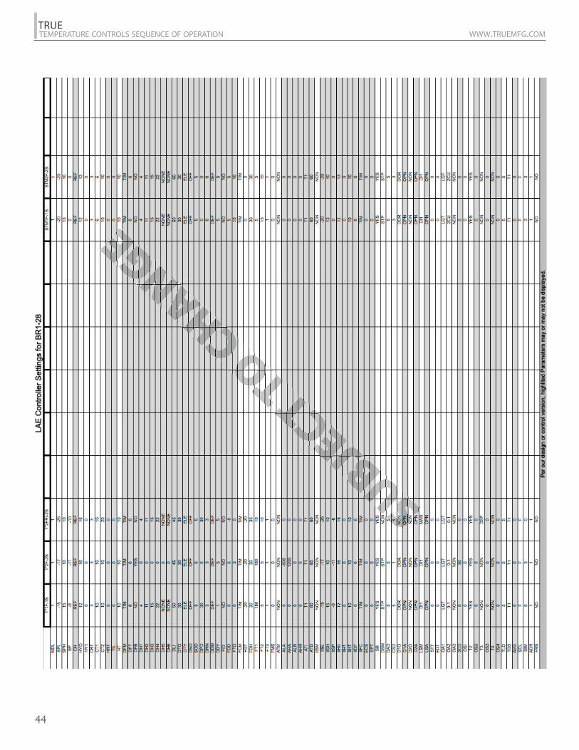
LAE CONTROLLER SETTING
BIT25 HEATING
LAE CONTROLLER SETTING
BR1-28
SPLSPHSPCMHYSTONTOFPBITDTARCTPF
HSDATMALAAHAALRAHRATDADOSBDI1DI2PSLPSRPOFDSMLSMOA1OA2OS1TLDSCLSIMADR
MODEL:
Per our design or control version, highlighted Parameters may or may not be displayed.
Parameters list settings are subject to change without prior notification.
Model specific parameters settings are on separate pages.
MODEL:
MDLSPLSPHSPC-HHYOHY1CRTCT1CT2HRTTILHT
DFMDFTDFBDH1DH2DH3DH4DH5DH6DLI
DTODTYDSOSODDPDDRNDDMDDYFIDFDDFTOFCMFDTFDHFT1FT2FT3
FMSATMALAAHAALRAHRATIATDIISMIISLIISHIISPIIH0IIH1IIHTIIDFIIFCECSEPTSB
DSMDADCSDD1OD1AD2OD2ALSMLSASTTEDTOA1OA2OA32CDOSIT2
OS2T3
OS3T4
OS4TLDTDSAVGSCLSIMADRFRS
SUBJECT TO C
HANG
MMADRADR BUBUBUBBUBUB
OC
GEGENG
22RT
TILHTHT
DFM
EGEGEGNGNNE
NGNGGNGNNEEEEE
35
TRUETEMPERATURE CONTROLS SEQUENCE OF OPERATION WWW.TRUEMFG.COM
36
TRUETEMPERATURE CONTROLS SEQUENCE OF OPERATION WWW.TRUEMFG.COM
37
TRUETEMPERATURE CONTROLS SEQUENCE OF OPERATION WWW.TRUEMFG.COM
38
TRUETEMPERATURE CONTROLS SEQUENCE OF OPERATION WWW.TRUEMFG.COM

39
TRUETEMPERATURE CONTROLS SEQUENCE OF OPERATION WWW.TRUEMFG.COM
40
TRUETEMPERATURE CONTROLS SEQUENCE OF OPERATION WWW.TRUEMFG.COM

41
TRUETEMPERATURE CONTROLS SEQUENCE OF OPERATION WWW.TRUEMFG.COM
42
TRUETEMPERATURE CONTROLS SEQUENCE OF OPERATION WWW.TRUEMFG.COM

43
TRUETEMPERATURE CONTROLS SEQUENCE OF OPERATION WWW.TRUEMFG.COM
44
TRUETEMPERATURE CONTROLS SEQUENCE OF OPERATION WWW.TRUEMFG.COM

45
TRUETEMPERATURE CONTROLS SEQUENCE OF OPERATION WWW.TRUEMFG.COM
SUBJECT TO C
HANGE
GRAY- ThermostatBLUE - DefrostYELLOW - Display
LAE CURRENT PROBES
LAE PRIOR PROBES

46
TRUETEMPERATURE CONTROLS SEQUENCE OF OPERATION WWW.TRUEMFG.COM
LAE ELECTRONIC CONTROL CHANGE FROM MODEL AR1 AND MODEL AR2 TO MODEL BR1.
REASON FOR ADVISMENT: LAE Electronic Control model update will change the display, connecting cable, module, wiring and programming*.
*Control is pre-programmed from the factory.New control is Universal voltage
NOTE: Below instructions do not pertain to cabinet models with display cable foamed in the wall.
True Manufacturing2001 E t T L
AR2Terminals
1
2
6
7
8
9
10 OR 11
14-19
26
27
28
29
30
31
32 (DOOR)
32 (D12)
33
BR1Terminals
1
2
4
5 OR 6
7
8 OR 9
10 OR 11
13-18
23
24
20
21
22
25
27
27
26
BR1 DISPLAY, CABLE AND MODULE CONNECTIONSAR2 DISPLAY, CABLE AND MODULE CONNECTIONS
33 26
32

47
TRUETEMPERATURE CONTROLS SEQUENCE OF OPERATION WWW.TRUEMFG.COM
control probe = return air defrost probe = coil
DANFOSS ELECTRONIC CONTROL REFRIGERATOR WITH DIGITAL DISPLAY GENERAL SEQUENCE OF OPERATION
DANFOSS ELECTRONIC TEMPERATURE CONTROL GENERAL SEQUENCE OF OPERATION
1. Cabinet is plugged in. a. Interior lights will illuminate on glass door models only. If the lights do not come on verify the light switch is in the “ON” position. Solid door cabinets may or may not have lights that may be controlled by the door switch. b. Cabinet will start in a Defrost Cycle. The duration for defrost will be a minimum of 4 minutes and a maximum of 60 minutes. c. The Danfoss Control Display will illuminate showing “deF”.
2. The Danfoss control is preprogrammed to initiate defrost every 4 hours of compressor run time. If deemed necessary by the Danfoss control additional defrost may occur at unspecified times. a. At this time the, evaporator fans will continue to run but the compressor will turn off. Some cabinets may also change the rotation of the reversing condenser fan motor. b. Once a preprogrammed temperature of the evaporator coil is reached, the Defrost Cycle will terminate and the 2 minute delay will start. c. After the 2 minute delay the compressor will restart. d. The Danfoss Control Display will continue to show “deF” for an additional 30 minutes.
3. The Danfoss control will cycle the compressor and the evaporator fan(s) on and off determined by the Set-Point and Differential temperatures. a. The Set-Point is the adjustable preprogrammed temperature which shuts off the compressor and evaporator fan(s). This is not the programmed cabinet temperature. b. The Differential is the non adjustable preprogrammed temperature that is added to the Set-Point temperature that will start the compressor and evaporator fan(s). c. The Danfoss control is designed to read and display a cabinet temperature not a product temperature. This cabinet temperature may reflect the refrigeration cycle of the Set-Point and its Differential. The most accurate temperature on a cabinets operation is to verify the product temperature.
Example: If the Set-Point is 34°F/1.1°C and the Differential is 6°F/3.3°C(Set-Point) 34°F + 6 (Differential) = 40°F
Or
(Set-Point) 1.1°C + 3.3 (Differential) = 4.4°CThe compressor will cycle off 34°F/1.1°C and back on at 40°F/4.4°C
48
TRUETEMPERATURE CONTROLS SEQUENCE OF OPERATION WWW.TRUEMFG.COM
DANFOSS ELECTRONIC CONTROL FREEZER WITH DIGITAL DISPLAYGENERAL SEQUENCE OF OPERATION
1. Cabinet is plugged in. a. Interior lights will illuminate on glass door models only. If the lights do not come on verify the light switch is in the “ON” position. Solid door cabinets may or may not have lights that may be controlled by the door switch. b. Cabinet will start in a Defrost Cycle. The duration for defrost will be a minimum of 4 minutes and a maximum of 30 minutes. c. The Danfoss Control Display will illuminate showing “deF”.
2. The Danfoss control is preprogrammed to initiate defrost every 4 hours of compressor run time. If deemed necessary by the Danfoss control additional defrost may occur at unspecified times. a. At this time, the compressor and evaporator fan(s) will turn off and the evaporator coil heater and drain tube heater will be energized. Some cabinets may also change the rotation of the reversing condenser fan motor. b. Once a preprogrammed temperature of the evaporator coil is reached, or 30 minutes, the Defrost Cycle will terminate and the 2 minute delay will occur. c. After the 2 minute delay the compressor will restart. d. The evaporator fans will remain off for an additional 3 minutes. e. The Danfoss Control Display will continue to show “deF” for an additional 30 minutes.
3. The Danfoss control will cycle the compressor and the evaporator fan(s) on and off determined by the Set-Point and Differential Temperatures. a. The Set-Point is the adjustable preprogrammed temperature which shuts off the compressor and evaporator fan(s). This is not the programmed cabinet temperature. b. The Differential is the non adjustable preprogrammed temperature that is added to the Set-Point temperature that will start the compressor and evaporator fan(s). c. The Danfoss control is designed to read and display a cabinet temperature not a product temperature. This cabinet temperature may reflect the refrigeration cycle of the Set-Point and it’s Differential. The most accurate temperature on a cabinets operation is to verify the product temperature.
Example: If the Set-Point is -6°F/1°C and the Differential is 6°F/4°C(Set-Point) -6°F + 6 (Differential) = 0°F
Or
(Set-Point) -21.4°C + 3.3 (Differential) = -18.1°CThe compressor will cycle off -6°F/-21.4°C and back on at 0°F/-18.1°C
49
TRUETEMPERATURE CONTROLS SEQUENCE OF OPERATION WWW.TRUEMFG.COM
DANFOSS ELECTRONIC CONTROL REFRIGERATOR WITHOUT DIGITAL DISPLAYGENERAL SEQUENCE OF OPERATION
DANFOSS ELECTRONIC CONTROL FREEZER / GC WITHOUT DIGITAL DISPLAYGENERAL SEQUENCE OF OPERATION
1. Cabinet is plugged in. a. Interior lights will illuminate on glass door models only. If the lights do not come on verify the light switch is in the “ON” position. Solid door cabinets may or may not have lights that may be controlled by the door switch. b. Cabinet will start in a Defrost Cycle. The duration for defrost will be a minimum of 4 minutes and a maximum of 60 minutes.
2. The Danfoss control is preprogrammed to initiate defrost every 4 hours of compressor run time. If deemed necessary by the Danfoss control additional defrost may occur at unspecified times. a. At this time, the evaporator fans will continue to run but the compressor will turn off. Some cabinets may also change the rotation of the reversing condenser fan motor. b. Once a preprogrammed temperature of the evaporator coil is reached, the Defrost Cycle will terminate and the 2 minute delay will start. c. After the 2 minute delay the compressor will restart.
3. The Danfoss control will cycle the compressor and the evaporator fan(s) on and off together. a. The temperature control is sensing the discharge air temperature. b. The temperature control should be set on the #4 or #5. c. The warmest setting is #1, the coldest is #9, and #0 is the off position. d. The thermometer is designed to read and display a cabinet temperature not a product temperature. This cabinet temperature may reflect the refrigeration cycle determined by the temperature control. The most accurate temperature on a cabinets operation is to verify the product temperature.
1. Cabinet is plugged in. a. Interior lights will illuminate on glass door models only. If the lights do not come on verify the light switch is in the “ON” position. Solid door cabinets may or may not have lights that may be controlled by the door switch. b. Cabinet will start in a Defrost Cycle. The duration for defrost will be a minimum of 4 minutes and a maximum of 30 minutes.
2. The Danfoss control is preprogrammed to initiate defrost every 4 hours of compressor run time. If deemed necessary by the Danfoss control additional defrost may occur at unspecified times. a. At this time, the compressor and evaporator fan(s) will turn off and the evaporator coil heater and drain tube heater will be energized. Some cabinets may also change the rotation of the reversing condenser fan motor. b. Once a preprogrammed temperature of the evaporator coil is reached, or 30 minutes, the Defrost Cycle will terminate and the 2 minute delay will occur. c. After the 2 minute delay the compressor will restart. d. The evaporator fans will remain off for an additional 3 minutes.
3. The Danfoss control will cycle the compressor and the evaporator fan(s) on and off together. a. The temperature control is sensing the discharge air temperature. b. The temperature control should be set on the #4 or #5. c. The warmest setting is #1, the coldest is #9, and #0 is the off position. d. The thermometer is designed to read and display a cabinet temperature not a product temperature. This cabinet temperature may reflect the refrigeration cycle determined by the temperature control. The most accurate temperature on a cabinets operation is to verify the product temperature.
50
TRUETEMPERATURE CONTROLS SEQUENCE OF OPERATION WWW.TRUEMFG.COM
OR
Turning On Power
Turning Off Power
Defrost
Cut Out Temperature
Celsius Temperature
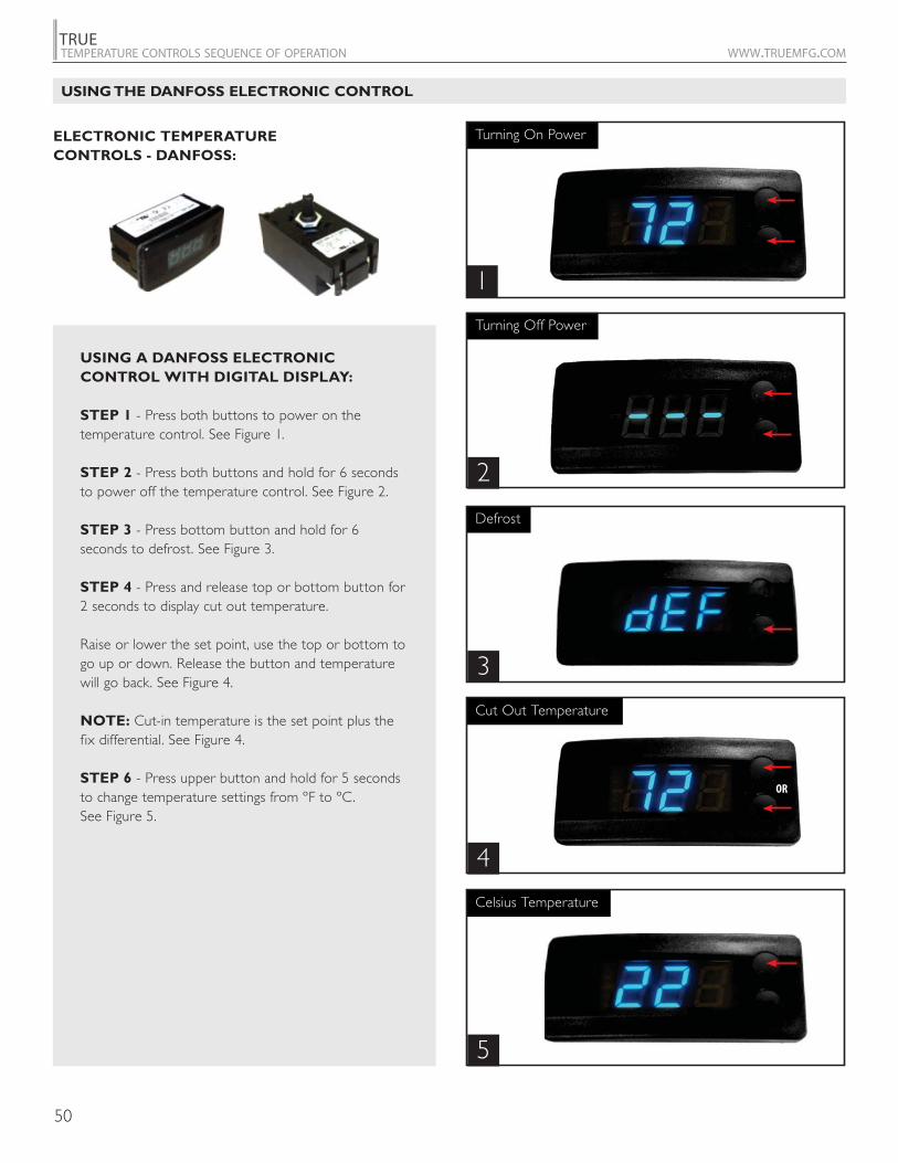
ELECTRONIC TEMPERATURE
CONTROLS - DANFOSS:
1
2
3
4
5
USING A DANFOSS ELECTRONIC
CONTROL WITH DIGITAL DISPLAY:
STEP 1 - Press both buttons to power on the temperature control. See Figure 1.
STEP 2 - Press both buttons and hold for 6 seconds to power off the temperature control. See Figure 2.
STEP 3 - Press bottom button and hold for 6 seconds to defrost. See Figure 3.
STEP 4 - Press and release top or bottom button for 2 seconds to display cut out temperature.
Raise or lower the set point, use the top or bottom to go up or down. Release the button and temperature will go back. See Figure 4.
NOTE: Cut-in temperature is the set point plus the fix differential. See Figure 4.
STEP 6 - Press upper button and hold for 5 seconds to change temperature settings from ºF to ºC. See Figure 5.
USING THE DANFOSS ELECTRONIC CONTROL
51
TRUETEMPERATURE CONTROLS SEQUENCE OF OPERATION WWW.TRUEMFG.COM
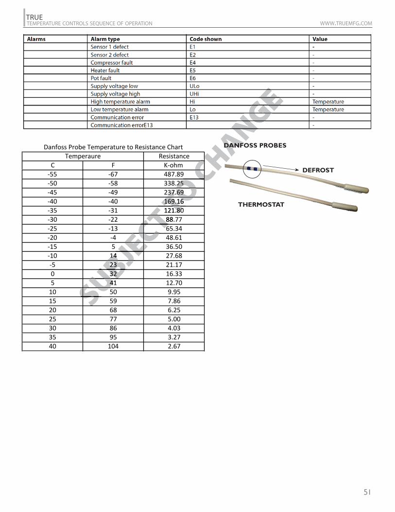
DEFROST
THERMOSTAT
DANFOSS PROBES
SUBJECT TO C
HAN
EC
CH
S
CHCHO
COTOTT T
CTECEC
JEBJUBUB
SUSS
DANFODANFO
DEFROST
THERMOSTAT

52
TRUETEMPERATURE CONTROLS SEQUENCE OF OPERATION WWW.TRUEMFG.COM
NOTES

53
TRUETEMPERATURE CONTROLS SEQUENCE OF OPERATION WWW.TRUEMFG.COM
NOTES

54
TRUETEMPERATURE CONTROLS SEQUENCE OF OPERATION WWW.TRUEMFG.COM
NOTES

55
TRUETEMPERATURE CONTROLS SEQUENCE OF OPERATION WWW.TRUEMFG.COM
NOTES

56
TRUETEMPERATURE CONTROLS SEQUENCE OF OPERATION WWW.TRUEMFG.COM
NOTES