TABLE OF CONTENTS - Spartanburg Water located in ... · technical specifications for water...
143
TECHNICAL SPECIFICATIONS FOR WATER DISTRIBUTION SYSTEM IMPROVEMENTS SPARTANBURG WATER SYSTEM SPARTANBURG, SOUTH CAROLINA Approved by SCDHEC JULY 15, 2008
Transcript of TABLE OF CONTENTS - Spartanburg Water located in ... · technical specifications for water...

TECHNICAL
SPECIFICATIONS
FOR
WATER DISTRIBUTION
SYSTEM IMPROVEMENTS
SPARTANBURG WATER SYSTEM
SPARTANBURG, SOUTH CAROLINA
Approved by SCDHEC JULY 15, 2008

PREFACE
In an attempt to standardize the water distribution systems being deeded to or constructed for the
Spartanburg Water System (SWS), we have developed the following specifications for items that shall
be incorporated into the design and construction of all water distribution systems. The basis for these
specifications is the SOUTH CAROLINA DEPARTMENT OF HEALTH AND
ENVIRONMENTAL CONTROL R.61-58 State Primary Drinking Water Regulations. These
specifications shall be followed. If they must be deviated from, you shall contact the Spartanburg
Water Engineering Department, and discuss the reasons for the deviation. We are aware that not all
items will work in all situations and must ask for your cooperation in working with SWS to resolve
problem areas. If you have any comments concerning these specifications, please feel free to contact
us at 864-585-9142.
These specifications will be updated periodically as deemed necessary. It is your responsibility to
contact SWS to verify that the revision you are working with is the most recent. All standards cited in
the text refer to the latest revision of that standard under the same specification number or to
superseding specifications with a new number.
Please refer to the Spartanburg Water Developers Manual for a detailed explanation of procedures
and requirements that a developer must follow in order to plan, construct, and have SWS accept, a
water extension for operation and maintenance.

TABLE OF CONTENTS
PAGE
SECTION 1 GENERAL PROVISIONS
1-01 INTENT AND SCOPE OF PLANS AND SPECIFICATIONS .............................. 1-1
1-02 MATERIALS AND WORKMANSHIP ................................................................. 1-1
1-03 SOURCE OF SUPPLY AND QUALITY OF MATERIALS .................................. 1-3
1-04 SAMPLES AND TESTING OF MATERIALS ...................................................... 1-3
1-05 PRECONSTRUCTION CONFERENCE ............................................................... 1-3
1-06 INSPECTION ....................................................................................................... 1-4
1-07 EXECUTION OF WORK ..................................................................................... 1-5
1-08 INSURANCE ........................................................................................................ 1-8
SECTION 2 RIGHTS-OF-WAY AND EASEMENTS
2-01 SCOPE .................................................................................................................. 2-1
2-02 WORK ON RIGHTS-OF-WAY AND EASEMENTS............................................ 2-1
2-03 WORK ON STATE AND COUNTY HIGHWAYS OR ROADS,
TOWN OR CITY ROADS OR STREETS,
RAILROAD AND OTHER UTILITY RIGHTS-OF-WAY .................................... 2-3
2-04 RESTORATION OF RIGHTS-OF-WAY: ............................................................. 2-5
SECTION 3 MATERIAL SPECIFICATIONS FOR PIPE AND FITTINGS
3-01 SCOPE .................................................................................................................. 3-1
3-02 DESIGN CRITERIA ............................................................................................. 3-1
3-03 DUCTLE IRON WATER PIPE (3-inch through 64-inch) ...................................... 3-2
3-04 PVC PIPE (1-inch through 12-inch) ...................................................................... 3-4
3-05 HIGH DENSITY POLYETHYLENE (HDPE) PIPE ............................................. 3-8
3-06 STEEL PIPE ......................................................................................................... 3-9
3-07 FITTINGS ............................................................................................................. 3-9
3-08 STEEL COUPLINGS AND BELL JOINT CLAMPS ............................................ 3-10
SECTION 4 WATER MAIN INSTALLATION AND TESTING
4-01 SCOPE .................................................................................................................. 4-1
4-02 DESIGN CRITERIA ............................................................................................. 4-1
4-03 EXISTING UTILITIES AND STRUCTURES ...................................................... 4-1
4-04 TRENCH EXCAVATION GENERAL .................................................................. 4-3
4-05 INSTALLATION OF DUCTILE IRON PIPE AND FITTINGS ........................... 4-8
4-06 INSTALLATION OF PVC PIPE .......................................................................... 4-17
4-07 INSTALLATION OF HDPE PIPE ....................................................................... 4-24
4-08 CROSS-CONNECTION CONTROL
(BACKFLOW PREVENTION DEVICES) ........................................................... 4-28
4-09 INSTALLATION OF TRACER WIRE AND WARNING TAPE ......................... 4-29
4-10 TESTING, DISINFECTION, CLEAN-UP AND PLACING IN SERVICE ........... 4-30

PAGE
SECTION 5 VALVES AND TAPS - MATERIALS AND INSTALLATION
5-01 SCOPE .................................................................................................................. 5-1
5-02 DESIGN CRITERIA ............................................................................................. 5-1
5-03 GATE VALVES .................................................................................................... 5-1
5-04 BUTTERFLY VALVES ........................................................................................ 5-2
5-05 AIR AND VACUUM VAVLES ............................................................................ 5-4
5-06 MANHOLES ......................................................................................................... 5-5
5-07 BALL VALVES - SWING CHECK VALVES ..................................................... 5-6
5-08 TAPPING SADDLES AND SLEEVES ................................................................. 5-6
5-09 LINE STOPS AND VALVE INSERTIONS .......................................................... 5-7
5-10 SERVICE SADDLES AND CORPORATION STOPS.......................................... 5-7
5-11 VALVE INSTALLATION .................................................................................... 5-9
SECTION 6 FIRE HYDRANTS AND FIRE SERVICES:
MATERIALS AND INSTALLATION
6-01 GENERAL ............................................................................................................ 6-1
6-02 MANUFACTURE AND NOMENCLATURE ....................................................... 6-1
6-03 GENERAL CONSTRUCTION ............................................................................. 6-1
6-04 MATERIALS AND EQUIPMENT........................................................................ 6-3
6-05 PAINTING ............................................................................................................ 6-7
6-06 INSTALLATION .................................................................................................. 6-8
6-07 FIRE SERVICES .................................................................................................. 6-9
6-08 FIRE SERVICE VAULTS .................................................................................... 6-9
SECTION 7 CLASSIFIED EXCAVATION,
7-01 GENERAL ............................................................................................................ 7-1
7-02 BLASTING ........................................................................................................... 7-1
SECTION 8 BORING AND AERIAL CROSSINGS
8-01 SCOPE .................................................................................................................. 8-1
8-02 BORING (INCLUDING JACK AND BORE, IMPACT MOLE,
CLOSED-FACE BORE, MICRO-TUNNELING AND OTHER) .......................... 8-1
8-03 HORIZONTAL DIRECTIONAL DRILLING (HDD)............................................ 8-6
8-04 PIPE SUPPORTED ON PIERS ............................................................................. 8-9
8-05 PIPE ATTACHED TO BRIDGES ......................................................................... 8-10
SECTION 9 PAVEMENT AND SURFACING
9-01 SCOPE .................................................................................................................. 9-1
9-02 DESIGN CRITERIA ............................................................................................. 9-1
9-03 CUTTING AND REPLACING PAVEMENT ....................................................... 9-1
9-04 REMOVING AND REPLACING SIDEWALK ..................................................... 9-2
PAGE
SECTION 10 GRASSING AND EROSION CONTROL
10-01 SCOPE .................................................................................................................. 10-1
10-02 MATERIALS ........................................................................................................ 10-1
10-03 INSTALLATION OF GRASS AND RELATED MATERIALS ............................ 10-5
10-04 TURF MAINTENANCE ....................................................................................... 10-9
10-05 EROSION CONTROL MEASURES ..................................................................... 10-10
10-06 EROSION CONTROL MATERIALS ................................................................... 10-13
10-07 EROSION CONTROL INSTALLATION ............................................................ 10-15
SECTION 11 WARRANTY
11-01 WARRANTY FOR ONE YEAR AFTER COMPLETION .................................... 11-1
11-02 MAINTENANCE .................................................................................................. 11-1

APPENDIX A STANDARD CONSTRUCTION DETAILS
NO. 1 SANITARY SEWER AND WATERLINE CROSSING DETAIL
NO. 2 TYPICAL TRENCHING DETAIL
NO. 3 PERMANENT “BLOW-OFF” DETAIL
NO. 4 CONCRETE THRUST BLOCK DETAIL
NO. 5 TYPICAL CONCRETE COLLAR DETAIL
NO. 6 DIP TO HDPE TRANSITION DETAIL
NO. 7 VALVE BOX DETAILS
NO. 8 WATER MAIN AIR RELEASE VALVE AND MANHOLE
NO. 9 TYPICAL FIRE HYDRANT INSTALLATION
NO. 10 CASING PIPE BORE AND JACK DETAIL
NO. 11 CARRIER PIPE INSTALLATION IN CASING
NO. 12 PIPE SUPPORTED ON CONCRETE PIERS
NO. 13 TYPICAL PAVEMENT REPAIR DETAILS

July, 2008 1-1
SECTION 1
GENERAL PROVISIONS
1-01 INTENT AND SCOPE OF PLANS AND SPECIFICATIONS
It is the intent of the plans and specifications that one shall supplement the other, but not
necessarily duplicate one another. Any work called for in one and omitted in the other shall
be executed as if called for in both in order that the work be fully completed according to the
complete design as determined by the Consulting Engineer (Engineer) and approved by the
Spartanburg Water System (SWS) Project Manager. Should any discrepancy appear in or
between the drawings and specifications, the specifications will govern. It is to be understood
that the work described in the specifications and shown on the plans shall be complete in
every detail whether every necessary item is particularly mentioned or not and the Contractor
shall be held to provide all items of labor and materials necessary for the satisfactory
completion of the indicated work. Any provisions contained in the specifications or shown on
the standard drawings which are not applicable to the work pertaining to this project shall be
disregarded. All testing shall be accomplished in accordance to these specifications and only
at the discretion of the SWS shall any portions of the testing be waived.
A. The Contractor shall check all dimensions, elevations, quantities and instructions
shown on the plans or given in the specifications and shall notify the Engineer should
any discrepancy of any kind be found in the plans, specifications or conditions at the
site. He will not be allowed to take advantage of any discrepancy, error or omissions.
If any discrepancy is discovered, the Engineer with Spartanburg Water System’s
approval will issue full instructions pertaining thereto and the Contractor shall carry
out these instructions as if originally specified.
B. The Specifications are divided into Sections for convenience of reference. The
materials, work, etc., mentioned or specified in one part are not intended to be limited
to that part only, but shall be applied with equal force to any other part or division of
work where such materials, work, equipment, etc., are mentioned or required to
properly provide for acceptable work according to the true intent of the drawings and
specifications. Reference to standard specifications (ASTM, AWWA, ANSI, etc.),
national codes, local or state codes and laws and ordinances shall mean the latest
edition of said document in effect at the time of taking bids unless specifically stated
otherwise.
C. Drawings shall be followed in construction of the work and all dimensions and
elevations shown on the Plans shall be accurately maintained. Scaled measurements
will not be allowed and no work shall be performed when dimensions or elevations are
not indicated until such dimensions or elevations are obtained from the Engineer.
1-02 MATERIALS AND WORKMANSHIP
It is the intent of these Specifications that the Contractor shall furnish first-class materials and
do all work in a first-class manner so that the completed job shall be thoroughly satisfactory in
every respect. To this end, the Contractor shall utilize all of his construction experience and
July, 2008 1-2
shall consult with the Engineer regarding items in the Plans and Specifications which may be
altered to the benefit of the work.
A. Materials, Services and Facilities: It is understood that except as otherwise
specifically stated in the specifications, the Contractor shall provide and pay for all
materials, labor, tools, equipment, water, light, power, transportation,
superintendence, temporary construction of every nature, and all other services and
facilities of every nature whatsoever necessary to execute, complete and deliver the
work within the specified time.
Materials must be approved for use before being purchased by the Contractor. The
Contractor shall submit to the Engineer a list of such materials or products, and the
shop drawings, together with such samples as may be necessary for determination of
their acceptability and obtain material/product approval. No request for payment will
be approved until this list has been received and approved by the Spartanburg Water
System Engineering Department. Delay caused by obtaining approvals for substitute
materials will not be considered justifiable grounds for an extension of construction
time.
B. Shop Drawings: Shop Drawings are original drawings prepared by the Contractor, or
a subcontractor or supplier, which illustrate some portion of the work and show
fabrication, layout, and setting or erection details. Shop drawings shall also include
manufacturer's catalog sheets, brochures, diagrams, schedules, performance charts,
illustrations and other standard descriptive data, as required. Shop drawings shall be
clearly marked to identify specific materials, finishes, products or models, and shall
show all required dimensions and clearances, performance characteristics and
capacities, wiring diagrams and controls.
1) The Contractor shall review and check all shop drawings for accuracy and
conformance with the contract documents. The Contractor's review shall
include verifying field measurements, field construction criteria, dimensions,
catalog numbers and similar data. Prior to submission to the Engineer, all
shop drawings shall be marked, stamped or otherwise certified as approved by
the Contractor, dated and signed or initialed. Any shop drawings not so
marked will be returned to the Contractor without the Engineer's review.
2) The Contractor shall schedule the submission of shop drawings to allow
sufficient time for review by the Engineer and the Spartanburg Water System,
corrections and resubmissions by the Contractor, and re-checking by the
Engineer/Spartanburg Water System, as necessary. The Engineer will review
shop drawings within two (2) weeks from date received.
3) A minimum of six (6) copies of each submittal indicating approval by the
Engineer shall be submitted to the Spartanburg Water System.
4) Distribution of shop drawings shall be:
a. SWS project file – One Copy

July, 2008 1-3
b. SWS M&C Department – Two Copies
c. Contractor – Three Copies
5) The Contractor shall not begin fabrication or work which requires submittals
until return of submittals with the full approval.
1-03 SOURCE OF SUPPLY AND QUALITY OF MATERIALS
The source of supply of all materials and equipment shall be submitted to the SWS
Engineering Department for review before orders are placed. Suppliers of reinforcing steel,
fabricated metal work, and metal castings may be required to submit guarantees of conformity
with the Drawings and Specifications. If required, representative preliminary samples of the
character and quality prescribed shall be submitted by the Contractor or producer for
examination and tested in accordance with the methods specified below. Only materials
conforming to the requirements of the specifications shall be used in the work. Any materials
proposed to be used may be inspected or tested during their preparation and use. If, after
inspecting and testing and/or trial, it is found that initial sources of supply do not furnish an
acceptable product in conformity with the Specifications, the Contractor shall be required to
furnish materials that comply with the specifications. No materials, which after approval have
become unfit for use, shall be used in the work or remain on the jobsite.
1-04 SAMPLES AND TESTING OF MATERIALS
Testing and certification of materials may be required by the Engineer if the quality of such
materials are in question. In the event the materials do not meet specifications, the Contractor
shall pay for the testing and provide materials which meet the specifications. If the materials
meet specifications, SWS will pay for the testing. Unless otherwise specified, materials tests
shall be made in accordance with the standards of the American Society for Testing and
Materials (ASTM), and by a commercial testing laboratory approved by the Engineer.
Reports of tests shall promptly be furnished to the Engineer. Test shall be arranged by the
Contractor as directed by the Engineer. The cost of all specified inspection and testing of
materials shall be paid by the Contractor.
1-05 PRECONSTRUCTION CONFERENCE:
A. Upon SCDHEC construction permit issuance, the Consulting Engineer shall contact
the SWS Project Manager to schedule a preconstruction conference. The conference
shall be scheduled no less than 72 hours in advance.
B. The conference shall be attended by:
- SWS Project Manager
- SWS Engineering Field Technician
- Representative of Consulting Engineer
- Representative of the Contractor and/or the Contractor's Project Foreman (preferred)
- Representative of any Subcontractors involved with project.

July, 2008 1-4
C. At least two (2) days prior to the preconstruction conference, the Consulting
Engineer shall provide the Spartanburg Water System Project Manager with four sets
of plans and specifications stamped "Issued for Construction". Project cut sheets and
applicable shop drawings shall be provided as soon as possible after the
preconstruction conference and prior to starting construction.
1-06 INSPECTION
The Engineer shall provide for the inspection of all materials used and all work done under
these specifications, by assistants and inspectors under his direction. Such inspection may
extend to any or all parts of the work and to the preparation or manufacture of materials
used, whether within the limits of the work or at any other place. The Contractor shall
furnish the Engineer all information relating to the work and to the materials which the
Engineer may deem necessary or pertinent and with such samples of materials as may be
required. The Contractor shall, at his own expense, supply labor and assistance as may be
necessary in handling material for proper inspection.
A. The representatives of the Owner, Engineer and any State, Federal or other agency
having jurisdiction over the work, shall have access to the work wherever it is in
preparation or progress, and the Contractor shall provide proper facilities for such
access and inspection.
B. Spartanburg Water System Engineering Field Technician shall be authorized to
inspect all work done and all materials furnished, including preparation, fabrication
and manufacture of the materials to be used. The Engineering Field Technician shall
not be authorized to alter or waive requirements of the Drawing and Specifications.
The Engineering Field Technician shall call to the attention of the Contractor to
failures of the work and/or materials to conform to the Drawings and Specifications.
The Engineering Field Technician may reject materials or suspend work until
questions at issue can be referred to, and decided by, the Spartanburg Water System
Project Manager or designated representative. The presence of the Engineering Field
Technician shall in no way lessen the responsibility of the Contractor.
C. The Contractor shall furnish all necessary facilities and assistance to make any
examination of the complete work if such examination is deemed advisable by the
Engineer. If any of the work is found defective in any respect, the Contractor shall
defray the expense of the examination and satisfactory reconstruction. If the work is
found acceptable, the expense of the examination shall be added to the Contractor's
final estimate.
D. Work covered up without consent or approval of the Spartanburg Water System
must, if required by the Engineering Field Technician, be uncovered for examination
and properly restored at the Contractor's expense.
E. If the Specifications, the Engineer's instructions, codes, laws, ordinances, or any
public authority require any work to be specially tested or approved, the Contractor
shall give the Engineer timely notice of its readiness for inspection; and, if the

July, 2008 1-5
inspection is by an authority other than the Engineer, of the date fixed for such
inspection.
F. Testing: During the course of the project, the Engineering Field Technician will
perform and/or witness various testing which is required by SCDHEC or the
Spartanburg Water System. The method of performing these tests is outlined in the
following sections of this document. The Engineering Field Technician will provide
the Contractor with the test results, and whether the results comply with the
requirements. The following is a list the testing which is generally required on water
main projects:
1) Soil Compaction Tests
2) Hydrostatic Pressure Tests
3) Bacteriological Tests
The installation of special fixtures or materials may require additional, specialized,
testing or documentation, which shall be noted on the approved plans. In these
cases, the Design Engineer will be responsible for conducting and witnessing the
specialized testing.
G. Final Inspection: Upon notice from the Contractor that work is complete, the
Engineer and Spartanburg Water System will make a final inspection, and will notify
the Contractor in writing of all defective, incomplete or otherwise unacceptable work
revealed by the inspection. The Contractor shall immediately correct all such
deficiencies to the satisfaction of the Engineer and Spartanburg Water System. Once
all deficiencies have been corrected, and all required testing has passed, the Engineer
will then certify the project in writing to SCDHEC, copying the Spartanburg Water
System, and request a final regulatory agency inspection.
1-07 EXECUTION OF WORK
A. VERIFICATION OF DIMENSIONS AND ELEVATIONS: Dimensions and
elevations indicated on the drawings in reference to existing structures, location of
utilities or other information on existing facilities, are the best available data
obtainable but are not guaranteed by the Engineer. The Engineer will not be
responsible for their accuracy. Before proceeding with any work dependent upon the
data involved, the Contractor shall field check and verify all dimensions, grades,
inverts, lines, elevations, or other conditions of limitations at the site of the work to
avoid construction errors or damage to existing facilities. If any work is performed by
the Contractor, or any subcontractors, prior to adequate verification of applicable
data, any resultant extra cost for adjustment of work necessary to conform to existing
conditions, or damage to existing facilities, shall be assumed by the Contractor
without reimbursement or compensation by the Owner.
B. If the Contractor, in the course of the work, finds any discrepancy between the
drawings and the physical conditions of the location, or any errors or omissions in
drawings or in the layout as given by survey points and instructions, he shall

July, 2008 1-6
immediately inform the Engineer, in writing. The Engineer will promptly investigate
the reported conditions and, after Spartanburg Water System approval, shall issue
such instructions as may be necessary for the proper execution of the work. Any
work done after such discovery and prior to receipt of such instructions shall be at the
risk of the Contractor.
C. CARE OF EXISTING FACILITIES: In executing the work, the Contractor shall
exert every effort not to damage any existing utilities or the Spartanburg Water
System existing facilities. Any damage that is done thereto shall be promptly repaired
by the Contractor or by the Owner, at the Owner's option, and at the Contractor's
expense. Damage to SWS lines shall be repaired by the SWS personnel. The
contractor shall not interrupt or interfere with the operation of existing utilities or
facilities during construction except when absolutely necessary. When this is the case,
he shall consult with the Engineer, Owner and the utility company as to procedure,
and shall be governed by their decision. Any damage done shall be promptly reported
to the affected utility for repair. Damage to SWS existing facilities shall be repaired
promptly.
D. The Engineer does not guarantee that all existing facilities such as buildings, fences,
pipelines, electrical lines, conduit, telephone cable, service connections, or other
facilities are shown on the plans. It shall be the Contractor's responsibility to locate
and protect all such existing facilities prior to beginning construction.
E. Contractor's Responsibilities. Contractor shall conduct his operations in a manner and
sequence which will provide for the continued transportation of wastewater flows
during construction of this project. Contractor shall take all actions required to
prevent discharge of sewer flow from the system to the ground or any stream. Any
construction actions that impede or interrupt flow shall be carefully executed and
monitored to prevent surcharging and overflow.
F. Any existing surface or subsurface improvements, such as pavement, curbs, sidewalks,
pipe or utilities, footings, or structures (including portions thereof), trees and
shrubbery, not indicated on the drawings or noted in the specifications as being
removed or altered shall be protected from damage during construction of the project.
Any such improvements damaged during construction of the project shall be restored
to a condition equal to that existing at time of award of contract.
G. Any such improvements damaged during construction of the project shall be restored
to a condition equal to that existing at time of award of contract. All repairs to utility
services shall be coordinated with the applicable utility company, and shall be made in
strict accordance with their requirements.
H. CONNECTING TO EXISTING WORK: It shall be the express responsibility of the
Contractor to connect his work to each part of the existing work or work previously
installed as required by the drawings and specifications to provide a complete
installation. Connections to existing water lines, prior to completion, may be allowed
by the SWS on a case by case basis where requested by the Contractor and approved
by the Spartanburg Water System Project Manager; otherwise, connections to

July, 2008 1-7
existing water lines shall be made only after all inspections are completed and all
punch list items have been adequately addressed. In certain cases, due to the type of
pipe material, certain main transmission and other water mains in the Spartanburg
Water system may only be tapped by SWS personnel. The special condition will be
noted on the approved project drawings.
I. Contractor's Work Limits: The Contractor is to perform his work in compliance with
all State and Federal safety requirements within the specified public right-of-way or
right-of-way as procured by the Spartanburg Water System. The Contractor may
make his own arrangements for increased construction right-of-way at no additional
cost to the Owner. Any damage caused by the Contractor inside or outside of the
specified work limits will be the responsibility of the Contractor.
J. RECORD DRAWINGS: To enable the SWS to prepare record drawings, the
Contractor shall keep a complete set with accurate records of changes and/or
deviations from the contract documents and shop drawings. It shall show the project
as it was actually installed. The Contractor's record set of marked-up drawings, shop
drawings and specifications shall be kept at the job site during construction and be
available for inspection by the Owner. These marked-up drawings and specifications
shall be included in the package of final documentation submittals before final
payment is requested.
K. TRENCH BRACING: The Contractor is required by State and Federal law to have
on site a Competent Person to respond to the requirements for the safety of the job
site to include trench bracing. Spartanburg Water System personnel will not enter any
trench that does not meet with the regulations and, therefore, will not approve that
portion of construction until the site in question meets with requirements. The
Contractor is responsible to provide the necessary labor, equipment and material to
comply with the regulations and work within the right-of-way provided by the
Spartanburg Water System at no additional cost to the Owner.
L. ORDER AND SEQUENCE OF WORK: The prosecution, or sequence of the work
shall be as provided herein or as approved by the Engineer, which approval, however,
shall in no way affect the responsibility of the Contractor. All taps and line draining
for connecting lines will be coordinated with the SWS Engineering Department and
may not be constructed until approved. The Contractor shall schedule with the SWS
any construction work which requires interference with the waterworks operations.
M. HANDLING OF MATERIALS: Proper and suitable tools and equipment for the safe
and convenient handling of pipe and appurtenances are to be used. Special care shall
be taken to prevent damage to all pipe, appurtenances and surrounding property while
unloading, storing and stringing the pipe.
N. STRINGING OF PIPE: Stringing of pipe along the route of work will be allowed to
the extent of work which can be completed during a single work day. Unloading and

July, 2008 1-8
stringing pipe along the entire route is prohibited.
1-08 INSURANCE
The Contractor shall not start work under this contract until he has obtained all the
insurance required under this paragraph and such insurance has been approved by the
Owner. The Contractor shall not allow any subcontractor to start work on his subcontract
until the insurance required of the subcontractor has been so obtained and approved.
A. Compensation and Employer's Liability Insurance: The Contractor shall procure and
maintain during the life of the contract the statutory Workmen's Compensation and
Employer's Liability Insurance for all of his employees to be engaged in work on the
project under the contract. The Contractor shall require all subcontractors to provide
Workmen's Compensation and Employer's Liability Insurance of all their employees to
be engaged in such work.
B. General Public Liability and Property Damage Insurance: The Contractor shall
procure and maintain during the life of the contract General Public Liability and
Property Damage Insurance, including vehicle coverage, to protect him from all
claims for destruction of or damage to property, arising out of or in connection with
any operations under the contract, whether such operations be by himself or by any
subcontractor under him, or anyone directly or indirectly employed by the Contractor
or by a subcontractor under him. The amount of such insurance shall be not less than
the following limits of liability.
1) $500,000 for all damages arising out of bodily injury, including death, at any
time resulting therefrom, sustained by any one person in any one accident; and
$500,000 aggregate for any such damages sustained by two or more persons in
any one accident.
2) $200,000 for all property damage sustained by any one person in any one
accident; and $200,000 aggregate for any such damage sustained by two or
more persons in any one accident.
C. Special Hazards Insurance: Where special hazards are encountered in the work under
this contract, such hazards shall be covered by a rider to the policy or policies
required under subparagraph B in an amount not less than those stipulated under
subparagraph B. The Contractor shall be responsible for procuring this insurance
before performing any work involving special hazards.
D. Flood Insurance: The Contractor shall procure and maintain during the life of the
contract adequate flood insurance to cover all work on this project.
E. Certificates of Insurance: Prior to starting any work, the Contractor shall furnish the
Owner with certificates showing the type, amount, class of operations, effective dates
and expiration dates of all insurance policies. Each certificate shall contain the
following statement: "The insurance covered by this certificate shall not be
cancelled or materially altered, except after ten (10) days written notice has been

July, 2008 1-9
received by the Owner."
F. Railroad Insurance:
1) The Contractor shall be able to furnish the Railway Company the following:
a) Certificate of Workmen's Compensation or Employer's liability insurance
according to the laws of the State.
b) Certificate of the contractor's Public Liability Insurance, to protect the
Contractor and Subcontractor:
1) For loss of life or injury to any one person in an amount not less
than $150,000 for any one person and not less than $300,000 for
any one accident.
2) For property loss or damage in an amount not less than $150,000
for any one accident and not less than $300,000 aggregate.
c) The original policy of Railroad Protective Liability Insurance naming the
Railway Company as the insured.
1) For loss of life or injury to any one person in the amount not less
than $150,000 for any one person and not less than $300,000 for
any one accident.
2) For property loss or damage in an amount not less than $150,000
for any one accident and not less than $300,000 aggregate.
July, 2008 2-1
SECTION 2
RIGHTS-OF-WAY AND EASEMENTS
2-01 SCOPE:
This section covers the requirements and work pertaining to the rights-of-way and
easements necessary for the construction of the project.
2-02 WORK ON RIGHTS-OF-WAY AND EASEMENTS:
A. The Owner will obtain all land and rights-of-way necessary for all work under this
contract, except for County, Town or City roads or streets. If all land and rights-of-
way are not obtained before construction begins, the Contractor shall start work only
upon such land and rights-of-way previously obtained by the Owner, and no claims
for damages will be allowed because of such delay. If the Owner is unable, for any
reason, to obtain the land and rights-of-way necessary for the work, the contract time
will be extended as required to cover the time lost by such delay. The Contractor
shall secure copies of all applicable right-of-way plats to be kept at the job site during
construction.
B. Contractor shall confine his construction operations to the immediate vicinity of the
location shown on the plans and in no case shall he encroach beyond the limits of the
Owner's property or rights-of-way. The exact location of the rights-of-way limits
shall be shown on the rights-of-way plats which will be furnished to the Contractor.
He shall place materials, equipment, supplies, etc., so as to cause the least possible
damage to property and interference with traffic. His method of operation and
placing of equipment shall be subject to the approval of the Engineer. Any damage
done to property outside the rights-of-way limits shall be the financial responsibility of
the Contractor. Any vehicular access to right-of-way which crosses private property
shall be by written permission of the property owner with copy of same provided to
District Engineering Field Technician.
C. It shall be the duty of the Contractor to locate the limits of the rights-of-way, or
property lines, prior to beginning construction. He shall be solely responsible for any
damage to trees, crops or other property outside the boundaries of the rights-of-way
and shall make satisfactory settlement for any damage directly with the property
owner involved.
D. Clearing and Grubbing. Contractor shall consult with the Spartanburg Water
Engineering Department and Engineer prior to beginning clearing and a full
understanding is to be reached as to procedure. Contractor shall then conduct
clearing and grubbing operations in strict accordance with these agreements
July, 2008 2-2
E. All operations shall be conducted with full consideration of all proper and legal rights
of the Owner, adjacent property owners and the public, and with the least possible
amount of inconvenience to them. Care shall be taken to protect adjacent property.
F. Contractor shall perform all clearing and grubbing work required for the installation of
the complete work. Clearing shall consist of the removal and disposal of all
pavement, stumps, trees, brush, debris, or other such materials in the path of the
work.
G. No burying of cleared debris on the right-of-way will be allowed.
H. Any vehicular access to the right-of-way which crosses private property shall be by
written permission of the property owner with copy of same provided to the
Engineering Field Technician.
I. Erosion control measures as shown on the plans, and/or as required by SECTION 10:
GRASSING AND EROSION CONTROL, shall be put in place during clearing and
grubbing and before trench excavation.
J. Clearing Along Right Of Way: Where trees, brush, stumps or exposed roots exist
within rights-of-way, the full width of the right-of-way shall be completely cleared and
grubbed. Stumps shall be removed and roots shall be grubbed at least two (2) feet
below the ground surface.
K. Burning Of Cleared Material shall be in strict accordance with all applicable local,
state and federal regulations pertaining to open burning and smoke abatement. Prior
to burning, approval and where applicable written permits, must be obtained from all
applicable agencies;
L. Minor Structures may exist on the right-of-way. The disposition of the structures
shall be so noted as shown on the plans by either; (1) left in place in a condition equal
to prior to construction; (2) removed and disposed of by the Contractor; (3) removed
for construction and replaced in a condition equal to prior to construction; (4)
relocated as shown on the plans. If the Contractor notes structures on the right-of-
way that are not shown on the plans or the disposition is not noted on the plans, he
shall contact the SWS Engineering Department as to which of the above methods
shall be followed.
M. Removal and Replacement of Fences: Fences shall be removed as required by
construction and replaced to property owners' satisfaction with materials as good as
that which was removed. Temporary fencing, as required, shall be installed to
property owners' satisfaction until permanent fencing can be erected.
N. Trees or Shrubbery along the highways, roadways, and streets shall not be disturbed

July, 2008 2-3
unless absolutely necessary. Approval must be obtained from the SWS Engineering
Department prior to any such removal. Any such trees or shrubbery which may be
necessary to be removed shall be heeled in and replanted. Heeling in and replanting
shall be done under the direction of an experienced nurseryman. Trees or shrubbery
that die within twelve (12) months of replacement shall be replaced by the Contractor
at no expense to the Spartanburg Water System.
O. Construction Operations: All work along highways, streets and roadways shall be in
accordance with the following sequence of construction operations, so as to least
interfere with traffic.
1) Trenching, Laying and Backfilling: It is the intent of these specifications that
there shall be minimum interruption to traffic and all traffic control shall be in
accordance with the regulations and requirements of the South Carolina
Department of Transportation, Spartanburg County and/or the local
jurisdiction. By entering into the construction agreement, the Contractor
agrees to hold the Spartanburg Water System harmless from and against any
and all liabilities and claims of any nature whatsoever relating to or arising
from traffic control. The trench shall not be opened any further ahead of pipe
laying operations than is necessary for proper laying operations, and trenches
shall be progressively backfilled and consolidated, and excess material
removed immediately behind laying operations so as not to interfere with
traffic.
2) Shaping: Immediately after backfilling operations are complete, any damaged
cut and fill slopes, side ditches and ditch lines, shall be reshaped and returned
to original level and condition. Topsoil, sod and any other materials removed
from shoulders shall be replaced in accordance with the requirements of, and
to the full and complete satisfaction of the South Carolina Department of
Transportation, Spartanburg County, the local jurisdiction, and the
Spartanburg Water System.
3) Grassing: See SECTION 10: GRASSING AND EROSION CONTROL.
4) Capability: When installing pipelines and appurtenances, sufficient personnel
and equipment will be provided so as to simultaneously carry out all of the
above operations.
2-03 WORK ON STATE AND COUNTY HIGHWAYS OR ROADS, TOWN OR CITY ROADS
OR STREETS, RAILROAD AND OTHER UTILITY RIGHTS-OF-WAY:
A. The Contractor shall not begin excavation, grading, fill, storm drainage, paving and
any other construction or installations on any property or in any right-of-way of
streets, highways, public carrier lines, utility lines (either aerial, surface or subsurface),

July, 2008 2-4
etc. until the necessary permits are secured. The Contractor shall conform to all
requirements of the authorities having jurisdiction and to the applicable requirements
of the specifications. Contractor shall make all necessary arrangements with the
proper authorities, including approval of construction methods, etc., and shall pay all
costs charged in connection with work. Contractor shall notify the South Carolina
Department of Transportation at least 24 hours in advance of any work performed on
State roads and shall notify Spartanburg County Roads and Bridges at least 24 hours
in advance of any work performed on County roads.
B. The Contractor shall provide full time flagmen, with appropriate red flags, at all times
when work is in progress along highways. Suitable warning and descriptive signs
shall be placed at each end of the working area while work is in progress along
highways. These signs shall be well tended, and shall be placed at sufficient distances
from the work so that ample warning is given to approaching traffic. Signs shall be
adequately lighted at night. All traffic control devices and methods shall comply with
the latest edition of the Manual on Uniform Traffic Control Devices.
C. Where pipe is installed in open cut across a highway, the cut shall be immediately
backfilled and all work of repairing the pavement completed within the same week
that it is cut. The Contractor shall keep at least one full lane open for traffic at all
times. Any subsequent settlement shall be immediately corrected and repaired. Refer
to SECTION 9.03 for paving and surfacing specifications.
D. Where a pipeline crossing under a highway is installed within encasement pipe, the
encasement pipe shall be provided as specified in SECTION 8-02: BORING.
E. Unless otherwise indicated, no excavated material shall be placed on the pavement
side of the ditch along highways. The least possible amount of ditch shall be left open
when work is not in progress, and equipment shall be removed from the pavement and
shoulders during shutdown periods. Shoulders of roadways shall be left in good
acceptable condition, and all disturbed topsoil and grass shall be replaced.
F. The Contractor shall not begin work on any property of any Railroad until the
Spartanburg Water System has secured necessary permits. Contractor shall conform
to all requirements of the Railroad, or its authorized representatives, in the
construction of this portion of the work. The Contractor shall also pay the cost of
flagmen or other expenses of the railroad in protecting rail or vehicular traffic. He
shall notify the railroad of the time that the work will be done and shall not begin
work until authorized by Railroad officials.

July, 2008 2-5
2-04 RESTORATION OF RIGHTS-OF-WAY:
A. During construction, the Contractor shall maintain the site and adjacent public and
private property, including streets and highways, free from accumulations of waste
debris, rubbish and dirt caused by his operations. Dry materials and rubbish shall be
wet down as necessary to prevent blowing dust.
B. Immediately after completion of the work, or any substantial unit or portion of it, the
Contractor shall remove all unused material, refuse and dirt placed by him in the
vicinity of the work and shall leave the premises in a neat and orderly condition,
satisfactory to the Engineer.
C. The right-of-way shall be restored to the original condition. Horizontal benches shall
be provided to facilitate access to the site and shall be located where directed by the
Engineer and the Spartanburg Water System. Fill material, where required, shall be
free of grass, roots, rock and other objectionable material and shall be spread evenly
and properly compacted. The entire right-of-way shall be graded, dressed off and
cleaned up to the satisfaction of the Engineer, Spartanburg Water System, other
agencies having jurisdiction, and property owner, where applicable.
1) Where work is along streets or highways and dirt has been placed on the
pavement, the pavement shall be swept clean of all dirt after backfill has been
completed.
2) Site: The Contractor shall clean up behind the work as much as is reasonably
possible as the work progresses, but in no case shall the pipe laying operation
be more than 1000 feet ahead of complete cleanup. Federal regulations
require that temporary stabilization measures be implemented within 14 days
of the time when construction activities have been completed in an area of a
phased project.
3) Upon completion of the work and before acceptance of the Final Payment for
the project by the Owner, the Contractor shall remove all his surplus and
discarded materials, excavated material and rubbish from the roadways,
sidewalks, parking areas, lawns and all adjacent property; shall restore, in an
acceptable manner, all property, both public and private, which has been
disturbed or damaged during the prosecution of the work; and shall leave the
whole site in a neat and presentable condition.
4) Except where specifically directed otherwise by the property owner, the entire
construction right-of-way shall be provided with a permanent grass cover
within 30 days after backfilling. Topsoil shall be replaced and seed planted,
fertilized and watered until a grass cover satisfactory to the Engineer and
property owner is obtained. If necessary, a temporary grass cover shall be
provided until a permanent cover can be established. Grassing shall be as

July, 2008 2-6
specified in SECTION 10. If required by the property owner, shrubbery shall
be replaced to the satisfaction of the Engineer and the property owner.

July, 2008 3-1
SECTION 3
MATERIAL SPECIFICATIONS FOR PIPE AND FITTINGS
3-01 SCOPE
This section contains the current specifications for materials to be used in projects to be integrated
into the Spartanburg Water System. The Spartanburg Water System has established specific
manufacturers as the standard for various items within its system. Such standardization is for the
express purpose of expediting maintenance procedures. All requests for approval of an "or equal"
item must be submitted to the Spartanburg Water System in writing. All pipe, fittings, packing, joint
materials, valves and fire hydrants shall conform to Section C of the AWWA Standards and SCDHEC
R.61-58. All materials or products that contact potable water must be third party certified as meeting
the requirements of ANSI/NSF61. Metallic pipe and fittings shall be lead free in accordance with
R.61-58.4(F).
The following pipe materials are specifically prohibited from installation, as part of the Spartanburg
Water System, for the purpose of distributing potable water:
A. Asbestos Cement “AC” Pipe
B. Thermoplastic Pipe in above-grade applications.
3-02 DESIGN CRITERIA:
Reference Standards of the American National Standards Institute (ANSI) and American
Waterworks Association (AWWA)
A21.4/AWWA C104 Cement-Mortar Lining for Cast-Iron and Ductile-Iron Pipe and
Fittings for Water
A21.5/AWWA C105 Polyethylene Encasement for Gray and Ductile Cast-Iron Piping
for Water and Other Liquids.
A21.10/AWWA C110 Gray-Iron and Ductile-Iron fittings, 3" through 48" Inches for
Water and Other Liquids.
A21.11/AWWA C111 Rubber Gasket Joints for Cast-Iron and Ductile-Iron Pressure
Pipe and Fittings.
A21.15/AWWA C115 Flanged Cast-Iron and Ductile-Iron Pipe With Threaded
Flanges.
A21.16/AWWA C116 Fusion-Bonded Epoxy Coatings.
A21.50/AWWA C150 Thickness Design of Ductile-Iron Pipe.
A21.51 AWWA C151 Ductile-Iron Pipe Centrifugally Cast, In Metal Molds or Sand-
Lined Molds, for Water or Other Liquids.
A21.53/AWWA C153 Ductile-Iron Compact Fittings for 3" thru 48".
B16.1 Cast-Iron Pipe Flanges and Flanged Fittings, Class 25, 125, 250, and 800.
Reference Standards of the American Water Works Association (AWWA)
C200 Steel Water Pipe
C600 Installation of Ductile-Iron Water Mains and Appurtenances.
C651 Disinfecting Water Mains.

July, 2008 3-2
C900, C905 Polyvinyl Chloride (PVC) Pipe
C901-02, C906 High Density Polyethylene (HDPE) Pipe
3-03 DUCTILE IRON WATER PIPE (3-inch through 64-inch)
A. Ductile Iron Pipe shall be centrifugally cast and conform to ANSI/AWWA A21.51/
C151, latest edition.
The pressure Class, net weight of pipe without lining, length of pipe and name of
manufacturer shall be clearly marked on each length of pipe.
B. Push-on, mechanical joint, and restrained joint pipe shall have a minimum rated
working pressure of 150 psi. All buried pipe shall be (minimum) pressure class as
follows:
1) 4” – 12” Pressure Class 350
2) 14” – 20” Pressure Class 250
3) 24” Pressure Class 200
4) 30” – 64” Pressure Class 150
C. Flanged pipe shall be Thickness Class 53
D. The pipe shall be lined in accordance with ANSI/AWWA C104/ A21.4, latest edition.
The pipe shall have the standard thickness cement lining inside and bituminous coat
outside in accordance with ANSI/AWWA C104/A21.4. The inside cement lining
shall be treated with a seal coat of asphaltic material in accordance with
ANSI/AWWA C104/A21.4. The seal coat shall have no deleterious effect upon the
quality, color, taste or odor of potable water and shall be approved by National
Sanitation Foundation (NSF). Approved pipe manufacturers are as follows:
1) Griffin Pipe
2) American Pipe
3) U.S. Pipe
4) McWane Group (includes Atlantic States and Clow Products)
NOTE: All ductile iron pipe installed in the Spartanburg Water System shall be of
domestic manufacture which is defined as physically manufactured within the limits of
the continental United States of America.
E. Push-on and Mechanical Joints shall conform to ANSI A21.11/AWWA C111. The
pipe is to be supplied in minimum 18 foot lengths with either push-on joints or
mechanical joints.
1) Push-On Joints as supplied by the following manufacturers are approved.
a. Griffin Pipe Product: "Super Bell-Tite" joints;
b. American Pipe Product: "Fastite" joint;
c. U.S. Pipe Product "Tyton" joint;

July, 2008 3-3
d. McWane Group (includes Atlantic States and Clow Products) “Tyton”
joint 4” – 24” , “Fastite” joint 30” – 36”
2) Mechanical Joints in accordance with ANSI A21.11/AWWA C111
F. Restrained Joint Pipe shall conform to ANSI A21.11/AWWA C111.
1) American Pipe Product: Flex Ring.
2) U.S. Pipe Product: TR FLEX.
3) Griffin Pipe Product: SNAP-LOK.
4) McWane Group (includes Atlantic States and Clow Products)
G. Push-on Joint Restraint rubber gaskets shall conform to ANSI A21.11/AWWA
C111 with stainless steel locking segments vulcanized into gasket, and shall be
have an operating pressure of 250 psi or greater. The joints shall be capable of
being disassembled and are approved for use only on ductile iron pipe, 4” through
12” diameter inclusive.
Manufacturers:
1) U.S. Pipe Product: Field-Lok Gasket.
2) American Product: Fast Grip
H. External Restraint of DIP Bell and Spigot Joints
DIP bell and spigot joints may be restrained by the use of the following external
restraint fixtures only if specifically approved by the Spartanburg Water
Maintenance and Construction (M&C) or Engineering Departments. In all cases,
the installation of these fixtures shall be performed as specified by the
manufacturer, shall be shown on the approved plans, and shall be specifically called
out on the Record Drawings.
TABLE 3-1: DIP External Restraint Fixtures
Manufacturer Model # Notes
EBAA Iron Sales,
Inc.
MEGALUG Series 1700 Restraint Harness DIP Only
Ford Uni-Flange Series 1300 or 1390 DIP Only
Sigma Corporation One-Lok SLDH Restraint Harness DIP Only
I. Except as specifically listed above, no other unique, proprietary, or other pipe or
joint restraint method shall be approved as an “equal” prior to being submitted for
review by the Spartanburg Water Engineering Department.
J. Flanged Joints shall conform to ANSI A21.11/AWWA C115. Bolts and nuts shall
conform to ANSI A21.11/AWWA C111.
K. Lead Ban

July, 2008 3-4
1) Any pipe, solder, or flux which is used in the installation or repair of any
public water system shall be lead free.
2) Any pipe, solder, or flux which is used in any plumbing in a residential or
nonresidential facility which provides water, through connection to a public
water system, for human consumption shall be lead free.
3) Lead free shall be defined, when used with respect to solders and flux, as
those containing not more than 0.2 percent lead.
4) Lead free shall be defined, when used with respect to pipes and pipe fittings,
as those containing not more than 8.0 percent lead.
5) Leaded joints necessary for the repair of cast iron pipes shall be exempt from
the lead free requirement.
L. Natural rubber or other material which will support microbiological growth may not
be used for any gaskets, O-rings, and other products used for jointing pipes, valves, or
other appurtenances which will expose the material to the water. All gaskets shall be
AWWA approved.
M. Asbestos Cement Pipe
1) No asbestos cement pipe will be allowed to be installed.
2) If asbestos cement pipe is encountered during any work in the Spartanburg
Water system, use whatever methods needed to prevent damage to the pipe
and follow all applicable SCDHEC regulations.
3-04 PVC PIPE
A. GENERAL
PVC pipe shall be 4-inch through 12-inch nominal diameter in accordance with
AWWA C900, ASTM D2241 and ANSI/NSF 61. PVC pipe in diameters larger
than 12-inch is not approved for use anywhere in the Spartanburg Water System.
1) All PVC pipe shall be designed and manufactured in accordance with
AWWA C900, latest revision, from virgin polyvinyl chloride resin meeting
cell Class 12454-A or 12454-B as defined in ASTM D1784. All
compounds shall qualify for a rating of 4000 psi for water at 73.4 degrees
Fahrenheit per the requirements of PPI TR3.
a. PVC (as described and specified above) is the only type of
“thermoplastic” pipe approved for use in the Spartanburg Water
System;

July, 2008 3-5
b. Thermoplastic PVC pipe is not approved for use in any above-
grade application, and all installations of PVC must be installed
with the depth of cover specified in SECTION 4-04 (F) of these
specifications.
2) PVC pipe shall be pressure class 200 (DR14) furnished in ductile iron pipe
equivalent outside diameters in 20-foot lengths and shall be approved by
the National Sanitation Foundation (NSF) Standard 14.
3) Each length of PVC pipe shall bear markings indicating the following
information at intervals not to exceed five (5') feet: (1) manufacturer's
name or trademark, (2) nominal pipe size and OD base, (3) AWWA
material code designation, (4) dimension ratio, (5) AWWA pressure class,
(6) AWWA C900 designation, and (7) product record code.
4) All PVC pipe shall be elastomeric-gasket bell-end pipe. One gasket shall
be furnished with each length of PVC pipe.
5) The installation of solvent-weld PVC pipe and fittings, of any size, is
prohibited in the water distribution system which is owned and operated by
Spartanburg Water.
6) Gaskets and lubricants to be used with PVC pipe shall be made from
materials that are compatible with PVC and with each other, but that will
not support the growth of bacteria or adversely affect, in any way, the
quality of the potable water to be transported.
7) Fittings used in the laying of PVC pipe shall be iron fittings as described
below. Fabricated or molded PVC fittings will not be acceptable in any
application.
B. PVC PIPE INSPECTION
1) Each pipe shipment shall be inspected with care by the Contractor and the
SWS Engineering Field Technician. Any pipe which is warped, cracked,
discolored, abraded, misshapen, or otherwise damaged shall be considered
unsuitable and shall not be used. Any unsuitable material discovered
during the inspection or at any other time shall be removed from the job
site.
2) If the load shifted during transport, has broken packaging, or shows rough
treatment, each pipe length shall be carefully inspected for damage.
3) It is assumed that all handling and storage of the PVC pipe by all persons
who handle, transport, and/or store, these PVC pipe materials prior to their
delivery to the job site is in accordance with the requirements of the Uni-
Bell PVC Pipe Association. Any damage resulting from improper

July, 2008 3-6
handling, transportation, or storage prior to or during the time the pipe
material is on the work site shall cause the piping materials to be rejected.
C. SHIPPING, RECEIVING, UNLOADING PVC PIPE
1) Shipping: All pipe material shall be shipped in a manner to ensure that the
pipe is not damaged.
2) Receiving: When receiving the PVC pipe shipment at the job site, the
Contractor shall exercise established precautions.
3) Unloading: Preferred unloading is in package units using mechanical
equipment; however, the pipe can be unloaded individually by hand.
Mechanical equipment shall be operated so that it does not strike adjacent
pipe and that pipe being moved does not strike anything.
a. Unloading unpackaged PVC Pipe: PVC pipe may be unloaded and
moved individually by hand if not packaged or if mechanical
equipment is not available.
b. Unloading Package Units: When unloading package units, the
following instructions shall be carefully followed:
i. Remove restraints from the top unit loads;
ii. If there are boards across the top and down the sides of the
load which are not part of pipe packaging, remove them;
iii. Use a fork lift with thin chisel forks, extend forks (or front
end loader equipped with forks) to remove each top unit
(one at a time) from the truck. Remove back units first. Do
not run the forks too far under units as fork ends striking
adjacent units may cause damage. Insure forks are fully
engaged;
iv. If a fork lift is not available, a spreader bar with fabric straps
which are capable of handling the load (with straps spaced
approximately 8 feet apart and looped under the load) may
be used. Cables may also be used if cushioned with rubber
hose sleeves or other material to prevent abrasion of the
pipe
v. During the removal and handling, be sure that the units do
not strike anything. Severe impact could cause damage,
particularly during cold weather;
vi. Do not handle units with individual chains or single cables,
even if padded;
July, 2008 3-7
vii. Do not attach cables to unit frames or banding for lifting;
viii. Pipe package units shall be placed and stored on level
ground;
ix. Package units shall not be stacked more than eight feet high.
Units shall be protected by dunnage;
x. To unload lower units, repeat the above unloading process;
xi. If unloading equipment is not available, pipe may be
unloaded by removing individual pieces by hand. However,
care shall be taken to insure that pipe is not dropped or
damaged.
D. STORAGE REQUIREMENTS FOR PVC PIPE:
1) PVC pipe shall be stored, if possible, at the job site in the unit packages
provided by the manufacturer. Caution shall be exercised to avoid
compression, damage or deformation to the bell ends of the pipe. Pipe
shall be stored on level ground.
2) If stored as individual pieces, pipe shall be arranged and supported so that
there can be no compression, damage or deformation to the bell ends.
3) When unit packages of PVC pipe are stacked, insure that the weight of the
upper units does not cause deformation to the pipe in lower units.
4) PVC pipe unit packages shall be supported by racks or dunnage to prevent
damage to the bottom during storage. Supports shall be spaced to prevent
pipe bending.
5) When exposure to direct sunlight for an extended period is unavoidable,
PVC pipe shall be covered with opaque material while permitting adequate
air circulation above and around the pipe as required to prevent excessive
heat accumulation.
6) PVC pipe shall not be stored close to heat sources or hot objects such as
heaters, boilers, steam lines, engine exhaust, etc.
7) When unit packages of PVC pipe are stacked, insure that the height of the
stack does not result in instability which could cause stack collapse, pipe
damage or personnel injury.
8) The interior as well as all sealing surfaces of pipe, fittings and other
accessories shall be kept free from dirt and foreign matter.

July, 2008 3-8
9) Gaskets shall be protected from exposure to heat, direct sunlight, ozone,
oil, and grease.
E. HANDLING REQUIREMENTS FOR PVC PIPE:
i. When using fork lifts or other handling equipment, prevent damage to PVC
pipe.
ii. When handling PVC pipe, avoid impact blows, abrasion damage, and
gouging or cutting by metal surfaces or rocks. Avoid stressing bell joints
and damage of bevel ends.
iii. Pipe shall be lowered, not dropped, from trucks and into trenches.
iv. In preparation for pipe installation, placement of pipe (stringing) shall be as
close to the trench as practical and on the opposite side from the excavated
earth. Bell ends shall point in the direction of work progress.
v. Pipe stringing shall not extend further than 100 feet beyond the installation.
vi. In subfreezing temperatures, extra caution is required in handling PVC pipe
to prevent impact damage.
1. EXTERNAL RESTRAINT OF PVC BELL AND SPIGOT JOINTS
PVC bell and spigot joints may be restrained by the use of the following external
restraint harnesses only if specifically approved by the Spartanburg Water
Maintenance and Construction (M&C) or Engineering Departments. In all cases, the
installation of these fixtures shall be performed as specified by the manufacturer, and
shall be shown on the approved plans
TABLE 3-2: PVC Pipe External Restraint Harness
Manufacturer Model # Notes
EBAA Iron Sales, Inc. Series 1500 Bell Restraint Harness C-900 PVC
Ford Uni-Flange Series 1390 DR-14 PVC Only
Sigma Corporation Series PVP PV-Lok PVC Only
3-05 HIGH DENSITY POLYETHYLENE (HDPE) PIPE
A. HDPE PIPE MANUFACTURE
All HDPE pipe shall be designed in accordance with AWWA C901, latest edition, for
sizes 1-1/4” thru 3” IPS diameters and to the requirements of ASTM D3035. Pipe
4”IPS and DIPS sizes 4” and above shall be manufactured to the requirements of ASTM
F714 and AWWA C906, latest edition. Black PE materials used for the manufacture of
polyethylene pipe and fittings shall be PE 3408 high density polyethylene meeting ASTM

July, 2008 3-9
D3350 cell classification 345464C.
1) HDPE pipe shall be Pressure Class 200 (DR-9) or greater wall thickness.
2) The pipe is to be supplied in minimum 20 foot lengths with thermal butt fusion
joints in accordance with ASTM D3261.
B. INSPECTION
Pipe and fittings shall be carefully examined by the Contractor and the SWS Engineering
Field Technician for cracks and other defects immediately before installation, with
special attention to pipe ends. All defective pipe and fittings discovered during the
inspection or at any other time shall be removed from the job site.
3-06 STEEL PIPE
The existing Spartanburg Water distribution system includes several welded steel main
transmission water lines. In general, no new steel water lines shall be installed in the SWS
system. However, if the installation of a new steel water main has a clear benefit to the SWS
system, the design should be submitted to the SWS Engineering Department for
consideration. All steel pipe must be in accordance with AWWA C200 or ASTM A53 or
ASTM A120.
3-07 FITTINGS
A . Fittings shall be ductile iron fittings manufactured in accordance with ANSI/AWWA
C153/A21.53, latest revision. Where compact fittings are not available, fittings shall
be full size iron fittings manufactured in accordance with ANSI/AWWA C110/A21.10
and ANSI/AWWA C111/A21.11, latest revisions. The working pressure rating shall
be 350 psi.
B. Only MJ x MJ (for buried service) or Flange x Flange (for above-ground service) are
approved. Push-on or other socket-type joints are not approved in any application,
and proprietary restraining methods are not approved except as noted below.
C. Ductile iron shall be in accordance with ASTM A-536, latest revision, with minimum
physical qualities of 70,000 psi tensile strength, 50,000 psi yield strength and 5%
elongation.
D. Restraint of joints at MJ fittings shall be achieved through the installation of an
approved restrainer gland with “auto-torque” twist-off heads. See below:
TABLE 3-3: Approved Restrainer Glands for DIP and PVC with Ductile Iron
Fittings
Manufacturer Model # Notes
July, 2008 3-10
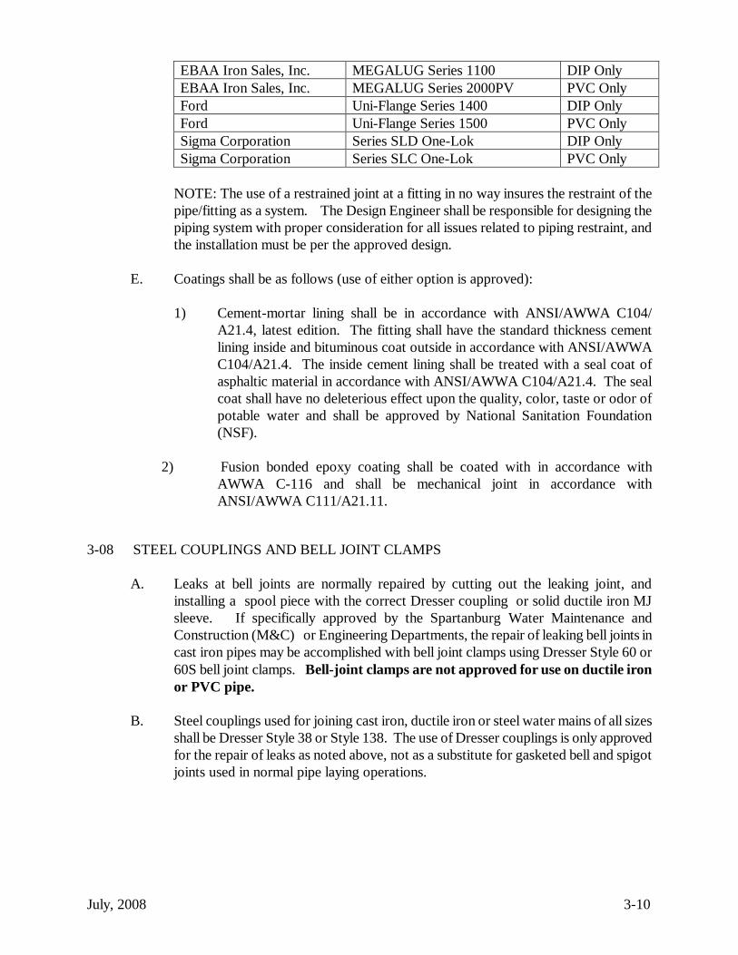
EBAA Iron Sales, Inc. MEGALUG Series 1100 DIP Only
EBAA Iron Sales, Inc. MEGALUG Series 2000PV PVC Only
Ford Uni-Flange Series 1400 DIP Only
Ford Uni-Flange Series 1500 PVC Only
Sigma Corporation Series SLD One-Lok DIP Only
Sigma Corporation Series SLC One-Lok PVC Only
NOTE: The use of a restrained joint at a fitting in no way insures the restraint of the
pipe/fitting as a system. The Design Engineer shall be responsible for designing the
piping system with proper consideration for all issues related to piping restraint, and
the installation must be per the approved design.
E. Coatings shall be as follows (use of either option is approved):
1) Cement-mortar lining shall be in accordance with ANSI/AWWA C104/
A21.4, latest edition. The fitting shall have the standard thickness cement
lining inside and bituminous coat outside in accordance with ANSI/AWWA
C104/A21.4. The inside cement lining shall be treated with a seal coat of
asphaltic material in accordance with ANSI/AWWA C104/A21.4. The seal
coat shall have no deleterious effect upon the quality, color, taste or odor of
potable water and shall be approved by National Sanitation Foundation
(NSF).
2) Fusion bonded epoxy coating shall be coated with in accordance with
AWWA C-116 and shall be mechanical joint in accordance with
ANSI/AWWA C111/A21.11.
3-08 STEEL COUPLINGS AND BELL JOINT CLAMPS
A. Leaks at bell joints are normally repaired by cutting out the leaking joint, and
installing a spool piece with the correct Dresser coupling or solid ductile iron MJ
sleeve. If specifically approved by the Spartanburg Water Maintenance and
Construction (M&C) or Engineering Departments, the repair of leaking bell joints in
cast iron pipes may be accomplished with bell joint clamps using Dresser Style 60 or
60S bell joint clamps. Bell-joint clamps are not approved for use on ductile iron
or PVC pipe.
B. Steel couplings used for joining cast iron, ductile iron or steel water mains of all sizes
shall be Dresser Style 38 or Style 138. The use of Dresser couplings is only approved
for the repair of leaks as noted above, not as a substitute for gasketed bell and spigot
joints used in normal pipe laying operations.

July, 2008 4-1
SECTION 4
WATER MAIN INSTALLATION AND TESTING
4-01 SCOPE
This section contains the current specifications for the installation of pipe, fittings, and all
related appurtenances in projects to be integrated into the Spartanburg Water System. All
pipe, fittings, packing, joint materials and appurtenances shall conform to and shall be
installed in accordance with Section C of the AWWA Standards and SCDHEC R.61-58. All
materials or products that contact potable water must be third party certified as meeting the
requirements of ANSI/NSF61.
4-02 DESIGN CRITERIA:
Reference Standards of the American Water Works Association (AWWA) Latest Revisions
B300 AWWA Standard for Hypochlorites
C111 Rubber-gasket Joints for Ductile Iron Pressure Pipe and Fittings
C200 Steel Water Pipe
C600 Installation of Ductile-Iron Water Mains and Appurtenances.
C651 Disinfecting Water Mains.
C900, C905 Polyvinyl Chloride (PVC) Pipe
C901-02, C906 High Density Polyethylene (HDPE) Pipe
4-03 EXISTING UTILITIES AND STRUCTURES
A. SCOPE: This Section pertains to the coordination with other utilities at the
construction site and instructions to prevent damage to other utilities.
B. GENERAL: It is the intent of these specifications that care shall be taken to prevent
damage to other utilities and structures. Any repairs shall be made at Contractor's
expense and in accordance with the particular utilities' requirements.
C. Existing Utilities: Utilities have been located based on information provided to the
Engineer by the utility companies. The Spartanburg Water System cannot guarantee
the accuracy of this information. At least 72 hours prior to installation, Contractor
shall contact Palmetto Utility Protection Service (PUPS) in Columbia, SC (1-800-
922-0983) and any other utility that may be in the area.
1) When interruptions of existing utilities occur, temporary service shall be
provided as approved by the Engineer and owner of the utility.
2) Underground Utilities and Other Structures: Necessary excavations to

July, 2008 4-2
determine the location and elevation of existing underground utilities and
other structures shall be made prior to the opening of trenches. Contractor
shall contact the utility and a representative of the utility shall be present when
excavating to locate utilities. When a conflicting utility has been located in the
field by the utility's personnel, or when there is direct knowledge of the
presence of one of these utilities in an area which will conflict with the
construction efforts, then the exact location of the conflicting utility shall be
verified by hand digging before any additional construction takes place. If the
utility's line is not uncovered in the staked position, then additional hand
digging shall be performed until either the utility's line is uncovered or until it
can safely be determined that it does not interfere with the proposed
construction and is not subject to damage during construction. Only after it is
confirmed that the conflicting utility will not be damaged shall the pipeline
construction efforts proceed.
3) Separations of Water Mains and Sewers:
The separation of water mains and sanitary sewers shall be in accordance with
Section R61-58.4.D(12) of the State Primary Drinking Water Regulations as
outlined herein.
a. Parallel installation - Water mains shall be laid at least 10 feet
horizontally from any existing or proposed sewer. The distance shall
be measured edge to edge. The water main may be allowed to be
installed closer to a sewer, provided that the water main is laid in a
separate trench or on an undisturbed earth shelf located on one side of
the sewer at such an elevation that the bottom of the water main is at
least 18 inches above the top of the sewer. However, any deviations
to the 10 feet horizontal distance must be approved by the
Engineering Department and DHEC.
b. Crossings - Water mains crossing sewers shall be laid to provide a
minimum vertical distance of 18 inches between the invert of the water
main and the top of the sewer. Where a water line crosses under a
sewer line, both the water and sewer line must be ductile iron. At
crossing, one full length of water pipe shall be located so both joints
will be as far from the sewer as possible. Special structural support
for the water and sewer pipes may be required. Refer to
CONSTRUCTION DETAIL NO. 1
c. Force mains - There shall be at least a 10 foot horizontal separation
between water mains and sanitary sewer force mains. There shall be
an 18 inch vertical separation at crossing as required in Part 1) and 2)
above.
d. Sewer manholes - No water pipe shall pass through or come in
July, 2008 4-3
contact with any part of a sewer manhole.
e. Water lines may come in contact with storm water piping or catch
basins if there is no other practical alternative, provided that ductile
iron is used, no joints of the water line are within the storm water
piping or catch basin and the joints are located as far as possible from
the storm piping or catch basin.
f. No water line shall be installed within 25 feet horizontally from any
portion of a wastewater tile/spray field. Also no water line shall be
installed within a contaminated area.
g. Special Conditions: When it is impossible to obtain the distances
specified in (a) and (b) above, the Contractor shall contact the SWS
Engineer. Any alternative design must first be approved by the SWS
Engineer and the South Carolina Department of Health and
Environmental Control. Any alternative design shall:
(i) maximize the distances between the water main and the sewer line
and the joints of each;
(ii) use approved water main piping materials for the sewer line; and,
(iii) allow enough distance to make repairs to one of the lines without
damaging the other.
D. Structures: Adequate temporary support and adequate protection and maintenance of
all underground and surface structures, drains, sewers, curbs, and other obstructions
encountered in the progress of the work shall be provided. The structures which have
been disturbed by the construction operations shall be restored to the satisfaction of
the utility involved upon completion of the work. ANY DAMAGES to existing
underground utilities shall immediately be reported to the Engineer and to the
appropriate utility.
4-04 TRENCH EXCAVATION GENERAL
A. SCOPE: Work consists of all necessary site grading, trench excavation and backfill,
and related work as shown on the plans and as specified herein.
B. GENERAL: All excavation and grading shall be confined to the right-of-way or
easement area as shown on the plans, and shall be done in an approved manner with
proper equipment. Excavation, filling and grading work shall be suspended during
rain and inclement weather, or when unsatisfactory field conditions are encountered,
unless otherwise directed by the SWS Engineering Department. At all times during
construction, Contractor shall maintain proper drainage in the construction area, and

July, 2008 4-4
shall take all measures necessary for erosion and sediment control as required in the
SECTION 10: GRASSING AND EROSION CONTROL.
C. Classification of Earthwork: Excavation shall be classified as either "common
excavation" or "rock excavation." "Rock excavation" shall be such materials which
cannot be removed by means other than by blasting or with a pneumatic or hydraulic
hammer. "Common excavation" shall include all types of materials that do not fall
into the category of "rock excavation" as defined above. Classification of excavation
shall be determined by the Engineer. It shall be the Contractor's responsibility to
notify the Engineer when rock excavation is encountered. The Contractor will not be
credited for any rock quantities excavated before such notice is given.
D. Excavation and Preparation: Trenches shall be excavated true to line and grade so
that the pipe can be installed to the alignment and depth required. The trench shall
not be opened any further ahead of pipe laying operations than is necessary for proper
laying and backfilling operations and as approved by the SWS Engineering
Department. Trenches shall be progressively backfilled within 100 feet of the pipe
laying and installation operations unless otherwise approved by the Engineering Field
Technician. No trenches may be left open overnight without the approval of the SWS
Engineering Department. When approved, proper traffic protection, lighting and
signs in accordance with requirements of South Carolina Department of
Transportation shall be provided by Contractor.
E. Width: The width of the trench shall be ample to permit the pipe to be laid and
jointed properly. Allowable widths of trenches are as follows:
PIPE SIZE
TRENCH WIDTH
(min/max)
PIPE SIZE
TRENCH WIDTH
(min/max)
3" or Under
6"/12"
20"
40"/44"
4"
18"/24"
24"
44"/48"
6"
24"/30"
30"
50"/54"
8"
24"/30"
36"
56"/60"
10"
24"/36"
42"
62"/66"
12"
24"/36"
48"
68"/72"
16"
30"/40"
Trenches shall be of such extra width, when required, to permit the placing of timber
supports, sheeting and bracing.
F. Depth of Cover: All pipe shall have a minimum cover of 48 inches. If 48 inches of
cover cannot be obtained (i. e. bridge crossings) ductile iron pipe shall be required and

July, 2008 4-5
adequate insulation shall be provided to prevent freezing.
G. Excavation to Grade: The trench shall be excavated to the depth required so as to
provide a UNIFORM AND CONTINUOUS ditch bottom between the bell holes.
Ledge rock, boulders and large stones must be removed to provide not less than 6
inches of soil cushion on all sides of the pipe and appurtenances. Any part of the
bottom of the trench excavated below the specified grade shall be corrected by adding
approved material and compacted to not less than 95% of the maximum dry density as
determined by a Standard Proctor Test (ASTM D698). The finished subgrade shall
be prepared accurately by means of hand tools.
H. Bell Holes: Bell holes shall be provided at each pipe joint to permit the jointing to be
properly made. Bell holes shall be excavated to sufficient depth and width,
approximately one (1") inch, to allow the pipe to rest uniformly on the bedding
material and to allow the joint to be properly made. The pipe bell shall not be used to
support the pipe.
I. Excavation in Soil: Where the bottom of the trench at subgrade is found to be
unstable or to include ashes, cinders, refuse, vegetable, or other organic material
which, in the opinion of the Engineering Field Technician should be removed, then the
material shall be removed to the width and depth required. Before the pipe is laid, the
subgrade shall be prepared by backfilling with an approved material in three (3") inch
uncompacted layers. Each layer shall then be thoroughly compacted, as specified
below in order to provide a uniform and continuous firm bearing and support for the
pipe at every point between bell holes.
J. Crushed Stone Stabilization: Wherever, in the opinion of the Engineering Field
Technician, the subgrade is by nature too soft or mucky for the proper installation of
the pipe, the trench shall be excavated as directed by the Engineer, and backfilled with
No. 67 Stone (3/4" and less) and brought to the grade required and compacted.
K. Excavated Material: All surface materials which are suitable for reuse in restoring the
surface shall be kept separate from the general excavated materials.
1) Storage of Excavated Material: All excavated material shall be stored in a
manner that will not endanger the work and which will avoid obstructing
sidewalks, driveways, or traffic. Fire hydrants under pressure, valve pit
covers, valve boxes, curb stop boxes, fire and police call boxes or other utility
controls shall be left unobstructed and accessible until the work is completed.
Gutters shall be kept clear or other satisfactory provisions made for street
drainage, and natural water courses shall not be obstructed. Rural mail boxes
shall be left unobstructed and accessible when possible.
L. Trench Bracing: The Contractor is responsible for the safety of the site. This is to
include complying with all safety regulations concerning trench bracing to State and
Federal requirements.

July, 2008 4-6
M. Dewatering: An adequate dewatering system shall be provided, if required by the
Engineering Field Technician. If a well-point system is used, the Contractor shall
submit plans to the SWS Engineering Department for approval. The system shall be
capable of removing any water that accumulates in the excavation and maintaining the
excavation in a dry condition while construction is in progress. Dirt placed on the
surface of the ground shall be sloped away from the excavation. If necessary, piping
shall be provided to prevent surface water from entering the excavation. Disposal of
water from the dewatering operation shall be done in a manner that does not interfere
with normal drainage, and does not cause damage to any portion of the work or
adjacent property. All drains, culverts, storm sewers and inlets subject to the
dewatering operation shall be kept clean and open for normal surface drainage. The
dewatering system shall be maintained until backfilling is complete or as otherwise
directed by the Engineering Field Technician. All damage resulting from the
dewatering operation shall be repaired by the Contractor to the satisfaction of the
Engineering Field Technician and at no cost to the Spartanburg Water System.
N. Trench Earth Dams: Where pipe bedding is angular material, earth dams, consisting
of a minimum ten (10) foot trench length of select compacted backfill to replace
angular bedding, shall be installed every 200 feet of pipe to prevent groundwater
movement in angular bedding material. Compacted backfill 95% proctor shall replace
angular bedding.
O. Backfilling Trenches – General (See also specific requirements in the applicable
sections for specific pipe materials)
1) All trenches shall be backfilled immediately after the pipe is laid in the trench
and bedding is complete, unless otherwise directed by the SWS Engineering
Field Technician. All opened trench shall be property backfilled before the
end of the working day unless the SWS Engineering Department specifically
approves leaving the trench open.
2) Initial backfill material shall be placed to a satisfactory height over the top of
the pipe (minimum 12-inches) for impact protection during the installation of
the remaining backfill. No mechanical tamps shall be used until this depth has
been achieved.
3) Bedding and backfill up to 12 inches over the top of the pipe shall be placed as
required above. Backfilling shall be carried up evenly on both sides of the
pipe. The remaining backfill may be placed in layers of up to 12-inches for
mechanical tamps, (18-inches if a mobile tamp is used) and each layer shall be
compacted to 95% standard proctor by using one of the approved tampering
devices listed in Paragraph 4) below. The tamping equipment shall make no
less than four (4) passes. One compaction run up the trench and back down
the trench is considered one pass.

July, 2008 4-7
4) Tamping Equipment: Mechanical tamps (gasoline driven), pneumatic tamps
(air tamp), and sheepsfoot trench rollers are acceptable. "Mobile tamps"
and/or "sheepsfoot trench rollers" such as "Rammax P-24EC" or approved
equal, are permitted.
5) Compaction Test: All backfill for water lines shall be subject to a compaction
test by Spartanburg Water System personnel or an independent laboratory
approved by the Spartanburg Water System. If compaction meets test
requirements, the Owner will pay for the cost of the test. If compaction fails
the test, the Contractor shall remove and replace backfill to the satisfaction of
the Spartanburg Water System, and shall also pay for the cost of the test and
any subsequent test required.
6) Contractor shall be responsible for final subsidence of all trenches, and shall
leave trenches flush with the original ground after all settlement has taken
place. Any settlement of backfill below finish grade shall be promptly
corrected. Trenches shall be protected against scour due to surface drainage.
Refer to CONSTRUCTION DETAIL NO. 2.
P. Underground Utilities: The Contractor is responsible for locating and protecting all
existing underground utilities as required in Section 4-03, EXISTING UTILITIES
AND STRUCTURES.
Q. Sequence of Work: Excavation, cleaning, laying, jointing, and backfilling shall be
kept up as closely as is possible so as to progress in a uniform, workmanlike manner.
In no case shall pipe be left in the trench overnight, without completing the joint. The
completed pipeline shall not be left exposed in the trench unnecessarily. The trench
shall be backfilled and compacted as soon as possible after laying and jointing is
completed. If necessary, exposed ends of pipe shall be properly plugged during laying
to prevent dirt and other materials entering the line. Each day at the close of work,
and at all times when laying is not in progress the exposed end of the pipeline in the
trench shall be closed by the use of an approved temporary water tight plug. If, at any
time, it becomes necessary to cover the ends of the uncompleted line with backfill, the
end of such pipeline shall be plugged with a water tight plug.
R. Flushing - The design shall provide for a readily accessible means of flushing all
water lines at a minimum velocity of 2.5 feet per second. This does not apply to
service lines.
1) Where dead-end lines occur they shall be provided with a fire hydrant if
flow and pressure are sufficient and if justified by line size and fire protection
requirements. Otherwise, a readily accessible blow-off valve shall be provided
for flushing purposes, except for the following cases:
a. Lines one and one half (1-1/2) inches in diameter and smaller
will not require blow-offs.

July, 2008 4-8
b. Two inch lines shorter than two hundred (200) feet will not require a
blow-off. However, a service connection shall be installed at the end
of the line or another acceptable means of bleeding chlorine through
the lines must be provided.
c. Blow-offs shall be sized to provide a minimum velocity of 2.5 feet per
second in the line and maintain a residual pressure of twenty-five (25)
pounds per square inch.
d. Lines ten (10) inches and larger require flows in excess of five
hundred (500) gallons per minute to achieve a two and a half (2.5)
feet per second scouring velocity. This would require a standard fire
hydrant or other approved blow-off, for flushing which must be
designed to provide at least five hundred (500) gallons per minute in
excess of peak hourly flow and a minimum residual pressure of twenty
(20) pounds per square inch.
e. No flushing device shall be directly connected to any sanitary sewer.
Refer to CONSTRUCTION DETAIL NO. 3
4-05 INSTALLATION OF DUCTILE IRON PIPE AND FITTINGS
A. GENERAL: All pipe and fittings shall be assembled and joined in accordance with
the instructions in this Section and shall accurately conform to the lines and grades
established by the plans.
1) Handling: Proper and suitable tools and equipment for the safe and
convenient handling and laying of pipe shall be used. Care shall be taken to
prevent the pipe or fittings coating from being damaged, particularly the
cement lining on the interior of the iron pipe. All pipe and fittings shall be
carefully examined for cracks, broken lining or other defects. No pipe or
fitting shall be laid which is known to be defective. If any pipe or fitting is
discovered to be cracked, broken or defective, after being laid, it shall be
removed and replaced with acceptable new pipe or fittings at no additional
cost. All pipe and fittings shall be thoroughly cleaned before being laid and
shall be kept clean until accepted in the completed work.
2) Cleaning Pipe and Fittings: All lumps, blisters and excess tar coating shall be
removed from the bell and spigot, and the inside of the bells shall be wire
brushed and wiped clean and dry and free from oil and grease or other foreign
material before the pipe is laid. If the interior of the pipe is not clean, the
entire length of pipe shall be SWABBED clean by the use of a circular cloth
swab having a diameter equal to the inside diameter of the pipe.

July, 2008 4-9
3) Placing in Ditch: Every precaution shall be taken to prevent foreign material
from entering the pipe while it is being placed in the trench. If the pipe laying
crew cannot place the pipe into the trench and in place without getting earth
into it, a heavy tightly woven canvas bag of suitable size shall be placed over
each end before lowering the pipe into the trench and left in place until the
connection is to be made. During laying operations, no debris, tools, clothing
or other material shall be placed in the pipe.
4) Whenever pipe laying is stopped, the open end of the line shall be closed with
a tight-fitting, inflatable, plug to keep out sand, earth, and water. An MJ cap
(with restrainer gland) may be used as an alternate if the pipe terminates in a
plain end. Any standing water shall be removed from the trench before the
plug or cap is removed. The plug should be tied off to prevent movement
under the influence of standing water in the ditch which may be present after a
heavy rain. Any dirt or foreign matter found in the pipe shall be thoroughly
removed before joining occurs.
5) In the event that the cap or plug fails to prevent the entry of standing water
and/or debris into the pipe, the pipe laying operation shall not commence until
the interior of the pipe has been cleaned to the satisfaction of the Engineering
Field Tech.
6) Permissible Deflection: Whenever it is necessary to deflect the pipe from a
straight line, either in the horizontal or vertical plane the maximum amount of
deflection allowed shall not exceed that listed in the table below. Joints shall
be pushed home straight before deflecting. For mechanical joint pipe, the
bolts shall be partially tightened before the length of pipe is deflected.

July, 2008 4-10
TABLE 4-1
MAXIMUM PIPE DEFLECTION AND TORQUE
Size Push-on Joint* Mechanical Joint* Torque nominal
degrees
inches
degrees
inches
ft-lbs
3 inch
4.0
15.0
4.5
17.0
60
4 inch
4.0
15.0
4.5
17.0
90
6 inch
4.0
15.0
4.5
17.0
90
8 inch
4.0
15.0
4.5
17.0
90
10 inch
4.0
15.0
4.5
17.0
90
12 inch
4.0
15.0
4.5
17.0
90
14 inch
2.0
7.5
3.0
11.0
90
16 inch
2.0
7.5
3.0
11.0
90
20 inch
2.0
7.5
2.0
7.5
90
24 inch
2.0
7.5
2.0
7.5
90
30 inch
1.5
5.5
2.0
7.5
120
36 inch
1.5
5.5
2.0
7.5
120
42 inch
1.5
5.5
1.5
5.5
150
48 inch
1.5
5.5
1.5
5.5
150
*18-foot joints
7) Cutting Pipe:
a. The cutting of pipe for installing valves, fittings or nipple pieces shall
be done in a neat and workmanlike manner without damage to the
pipe or lining and so as to leave a smooth end at right angles to the
axis of the pipe. Prior to cutting, the exact location of the cut shall be
carefully marked by chalk or some other means around the entire
circumference of the pipe. The cut shall be made following this mark.
The edge of the cut spigot shall be beveled a minimum of 1/4-inch
when "push-on" joints are involved.
b. A pipe saw shall be used for cutting all pipe. Any other method must
be approved by the SWS Engineering Department prior to

July, 2008 4-11
construction.
c. The flame cutting of any pipe by any means will not be allowed.
d. The minimum nipple length allowed without approval from the SWS
Engineering Field Technician is two feet (2’).
B. Push-On Joints ("Super Belltite", "Tyton", Fastite"): Jointing of compression ("Push-
on") joint pipe shall be made by experienced workers. Sockets, spigots, and gaskets
shall be thoroughly cleaned in accordance with AWWA C111 before the gasket is
inserted into the socket recess. At a minimum, the sockets and spigots shall be
cleaned with a wire brush. If the gaskets and spigots require additional cleaning and
lubrication, this shall be provided via an NSF approved soapy water solution or an
approved lubricant. However the lubricant cannot be vegetable shortening nor can it
support microbiological growth. Any lubrication shall be in accordance with
manufacturer's recommendation. The gasket shall be carefully placed into the socket
recess by hand, and evenly seated. A thin film of lubricant supplied by the pipe
supplier shall be applied to the inside of the gasket and outside of the spigot end of the
pipe to permit easy entry of the pipe into the socket. The spigot ends of cut pipe shall
be dressed and tapered with a coarse file or approved beveling device in a manner that
will protect the gasket from damage, permit the proper centering of pipe in the bell,
provide uniform compression of the gasket, and easy entry of spigot into socket. The
spigot end of the pipe shall be pushed "HOME" by the use of a large bar ratchet type
assembly tool, or jack, or other approved methods. Care must be taken in the use and
storage of the joint lubricant provided. Lubricant contaminated by dirt or other
material shall be discarded. During assembly of the next joint of pipe in the ditch, the
joint being installed must be kept straight and in line with the previous joint installed.
Pipe may be deflected if necessary but only after the assembly is completed.
C. Mechanical Joints: Joints for mechanical joint pipe shall be made by experienced
workers. Gaskets, sockets and spigots shall be cleaned and lubricated as stated in
paragraph "B" above. The spigot shall be pushed into position and seated evenly in
the socket. The gland shall be pushed into position for compressing the gasket. All
bolts and nuts shall be tightened to a uniform permanent tightness to the required
torque as shown in Table 4-1. Bolts shall be tightened beginning with the bottom
bolt, then the bolt directly opposite and proceeding around the joint using this
alternating procedure to provide uniform tightness around the pipe. Care shall be
taken to keep the gland square with the socket. The glands and bolts shall be kept
clean and sockets, spigots, and gaskets shall be kept clean until such joint has been
completed. Any joint which leaks shall be reassembled.
D. Restrained Joint Pipe: Where restrained joint pipe is called for on the plans, or is
otherwise required and approved by the Engineer, it shall be assembled and installed
in accordance with the manufacturers published instructions and recommendations.
E. Threaded Jointing: The threads of the coupling and pipe shall be inspected for defects

July, 2008 4-12
and, if satisfactory, all threads shall be thoroughly cleaned with a wire brush before
the joint is made. If the coupling is furnished "hand-tight", it shall be removed and all
threads cleaned with a wire brush before being reassembled and properly tightened.
The threaded end of the next joint to be assembled shall be squared with the coupling
and hand-tightened. Final uniform tightening of the pipe length and coupling shall be
accomplished by competent workers using the proper wrenches which shall not
damage the pipe coating. Teflon tape and Teflon pipe dope shall be used as lubricant
for all threaded joints.
F. Water Crossings: For all surface water crossings (above the water level) the pipe
shall be adequately supported and anchored as shown on the construction drawings in
order to protect the pipe from damage and freezing as well as to make the pipe
accessible for repair or replacement. For all underwater crossings, a minimum of two
(2) feet of cover shall be provided. For water crossings of 15 feet wide or greater, the
following shall be provided:
1) The pipe material and joints shall be designed appropriately;
2) Valves shall be located so that the section can be isolated for testing or
repair; the valves shall be easily accessible, and not subject to flooding; and,
3) A blow-off shall be provided on the side opposite the supply service, sized
in accordance with R.61-58.4(D)(7). Blow-offs shall not be directed
toward creeks or other water bodies without proper precaution taken to
dechlorinate prior to discharge.
Refer to SECTION 8: BORING AND AERIAL CROSSINGS.
G. All plugs, caps, tees, bends, and hydrants, and other items as may be indicated on the
plans, shall be provided with reaction blocking, tie rods, or other approved restraining
methods or as shown on the drawings for lines 2-inches in diameter and larger. This
includes fire hydrants on lines 6-inches in diameter and larger.
1) Concrete Blocking and Rodding:
a. Concrete used for blocking, collars and "Deadman" type thrust blocks
shall have a compressive strength of 3,000 psi at 28 days. High early
strength concrete shall be used.
b. Concrete shall be poured to the dimensions shown on the plans and
formed when directed by the Engineering Field Technician. The large
side (backs) of the blocking shall bear against undisturbed, hard, solid
earth. Blocking shall be poured to bear against the pipe or fitting and
allow sufficient area for repair and the easy removal of nuts and bolts.
The pipe or fitting shall be wrapped with 8 mil polyethylene
(according to AWWA C-105) for a suitable distance either side of the

July, 2008 4-13
thrust block to prevent the concrete from bonding to the pipe, fitting,
or fasteners. Refer to CONSTRUCTION DETAIL NO. 4.
c. Backfilling on poured concrete will not be permitted on concrete for
24 hours after pouring, and no water will be permitted in mains for at
least 24 hours after concrete blocking is poured.
d. Metal Straps and rods shall be made of steel having a tensile strength
of 95,000 psi. If required by the Engineer, the Contractor shall supply
acceptable certification of tensile strength. All steel components,
including rods, straps, nuts, bolts, couplings and clamps shall be
coated with 17.5 mils of Thick and Quick Mastic, or equal.
Contractor shall supply coating and coat all the tie rods, clamps and
miscellaneous steel used for anchoring purposes.
e. Concrete Collars poured on the last joint of pipe in a dead end run,
shall be poured around a thrust collar which shall be installed
according to the manufacturer’s recommendations (unless welded on,
which must be done at the factory). This collar shall be installed on
the pipe midway between the MJ bell and the spigot. Pipe
manufacturer's shop drawings must be submitted for each size collar
to be used indicating that the collar is designed to, at a minimum,
restrain the force created by a 250 psi line pressure as listed in the
table below. Field welding thrust collars will not be allowed. Refer
to CONSTRUCTION DETAIL NO. 5 and SECTION 3-03 Paragraph
I of these Specifications.

July, 2008 4-14
Pipe Size
Nominal Inch Test Pressure
(PSI) Thrust (LBS)
4 250 3,140
6 250 7,065
8 250 12,560
10 250 19,625
12 250 28,260
14 250 38,465
16 250 50,240
18 250 63,585
20 250 78,500
24 250 113,040
28 250 153,860
30 250 176,625
32 250 200,960
36 250 254,340
40 250 314,000
44 250 379,940
48 250 452,160
f. Certain applications require special thrust restraint procedures and
designs which should be submitted to the Spartanburg Water
Engineering Department for review.
H. Restrained Joint Pipe:
Restrained joint piping materials shall meet the requirements stated in Section 3-03G,
PIPE MATERIALS, and Section 3-06 FITTINGS, and shall be as those shown on
the shop drawings submitted by the Contractor and approved by the Engineer.
I. Pipe Bedding:
1) Pipe Bedding: All ductile iron pipe 3-inch through 20-inch diameter shall be
bedded on a flat trench bottom or on select material as described in B.(1)
below. All ductile iron pipe 24-inch through 42-inch diameter shall be bedded
on a 4-inch thick bed of angular material as described in B.(2) below. All pipe
bedding shall be continuous and uniform, have adequate support, and no
stones within six (6) inches of the pipe.
2) Bedding Materials: Materials for pipe bedding shall be as indicated on the
typical trench section (CONSTRUCTION DETAIL NO. 2), or as specified
herein
3) Select material shall be used from the angular material to the top of trench. It
shall be suitable material from the excavation free of large stones, hard lumps
of debris and other objectionable materials. If select material is not available
from the excavation, it shall be hauled to the site.

July, 2008 4-15
4) Angular material shall be crushed stone conforming to ASTM C33, Size No.
67 with a size not larger than 3/4-inch. Size No. 57 stone, which is
frequently more-readily available, may be used as a substitute.
5) Trench Earth Dams: Where pipe bedding is angular material, earth dams,
consisting of a minimum ten (10) foot trench length of select compacted
backfill to replace angular bedding, shall be installed every 200 feet of pipe to
prevent groundwater movement in angular bedding material. Compacted
backfill 95% proctor shall replace angular bedding.
J. BACKFILLING TRENCHES:
1) All trenches shall be backfilled immediately after pipes are laid in the trench,
unless otherwise directed by the Engineering Field Technician. All opened
trenches shall be properly backfilled before the end of the working day.
2) Backfilling: The backfilling of pipe trenches shall be as stated below
according to the pipe diameter.
3) Ductile iron pipe 4-inch to 12-inch diameter: The trench shall have a lightly
consolidated backfill (80% Standard Proctor) placed around the barrel of the
pipe, with fine material, free of large stones, hard lumps of debris and other
objectionable material, up to the top of pipe. Backfilling shall be carried up
evenly on both sides of the pipe. The remaining backfill may be placed in
layers of up to 12-inches for mechanical tamps, (18-inches if a mobile tamp is
used) and each layer shall be compacted to 95% standard proctor by using one
of the approved tamping devices listed in paragraph 5) below. The tamping
equipment shall make no less than four (4) passes. One compaction run up
the trench and back down the trench is considered one pass.
4) Ductile iron pipe 14-inch to 42-inch diameter: The trench shall be backfilled
to the top of the pipe with select material compacted to 95% standard proctor
by a narrow footed air tamp or narrow footed mechanical tamp. Remaining
backfill may be placed in layers of up to 12 inches. From the top of the pipe
to the top of ditch the backfill shall be compacted by using one of the
approved tamping devices listed in paragraph C below. All backfill shall be
compacted to 95% maximum Standard Proctor (ASTM D698). The tamping
equipment shall make no less than four (4) passes; more if necessary to obtain
the required compaction. One compaction run up the trench and back down
the trench is considered one pass. Compaction shall be such as to prevent
future settlement. The entire cross-section of the trench (from side to side of
trench and entire length) shall be compacted. No space in the trench shall be
left uncompacted.
5) Tamping Equipment: Mechanical tamps (gasoline driven), pneumatic tamps
(air tamp), and sheepsfoot trench rollers are acceptable. "Mobile tamps"

July, 2008 4-16
and/or "sheepsfoot trench rollers" such as "Rammax P-24EC" or approved
equal, are permitted.
6) Compaction Test: All backfill for water lines shall be subject to a compaction
test by Spartanburg Water System personnel or an independent laboratory
approved by the Spartanburg Water System. If compaction meets test
requirements, the Owner will pay for the cost of the test. If compaction fails
the test, the Contractor shall remove and replace backfill to the satisfaction of
the Spartanburg Water System, and shall also pay for the cost of the test and
any subsequent test required.
K. TEMPORARY SURFACING:
1) Temporary Surfacing of Trenches: Where trenches are in streets or across
roadways or driveways open to vehicular traffic, the remaining 6 inches of
backfill up to the traveled surface shall be made with compacted crushed
stone, ASTM C33 Gradation 67 with sufficient fines for compaction. Such
surface maintenance of trenches shall continue until permanent replacement of
street paving is completed.
2) Under Pavement, the top of the trench shall be filled with base for pavement
as specified in SECTION 9: PAVEMENT AND SURFACING. In unpaved
roads and shoulders, the top 6 inches of the trench shall be filled with
compacted topsoil.
3) Contractor shall be responsible for final subsidence of all trenches, and shall
leave trenches flush with the original ground after all settlement has taken
place. Any settlement of backfill below finish grade shall be promptly
corrected. Trenches shall be protected against scour due to surface drainage.
L. CONCRETE ENCASEMENT OF PIPE:
Where shown, and where otherwise directed, pipe shall be completely encased with
concrete as specified in SECTION 4-05, Paragraph H. The trench shall first be
excavated not less than six inches (6") below the bell of the pipe and the pipe laid to line
and grade on concrete blocking. Concrete shall then be placed to the full width of the
trench, but in no case less than six inches (6") from the pipe bell on either side of the
trench, and to a height of not less than six inches (6") above the top of the pipe bell. No
backfill material shall be placed in the trench for a period of at least twenty four (24)
hours after the concrete encasement has been placed. The water main shall be tested
before encasing in concrete.
M. CREEK OR RIVER CROSSINGS
1) Above-water crossings - The pipe shall be adequately supported and
anchored, protected from damage and freezing, and accessible for repair or

July, 2008 4-17
replacement. (Refer to SECTION 8 of these Specifications)
2) Underwater crossings - A minimum cover of two (2) feet shall be provided
over the pipe. When crossing water courses which are greater than fifteen (15)
feet in width, the following shall be provided:
a. The pipe material and joints shall be designed appropriately. There
are a number of proprietary flexible joint configurations which are
available, and shall be submitted to the SWS Engineering Department
for review.
b. Valves shall be located so that the section can be isolated for testing
or repair; the valves shall be easily accessible, and not subject to
flooding; and,
c. A blow-off shall be provided on the side opposite the supply service,
sized in accordance with SCDHEC R.61-58.4(D)(7).
d. Blow-offs shall not be directed toward creeks or other water bodies
without proper precaution being taken to dechlorinate prior to
discharge
4-06 INSTALLATION OF PVC PIPE
A. GENERAL: All pipe and fittings shall be assembled and jointed in accordance with
the manufacturer's instructions and with this section. When gaskets are color coded,
refer to the PVC pipe manufacturer's literature for significance. All work shall
accurately conform to the lines and grades established on the plans.
B. Handling: Proper and suitable tools and equipment for the safe and convenient
handling and laying of PVC pipe shall be used. Care shall be taken to prevent the pipe
or fittings from being damaged, particularly the lining on the interior of the iron
fittings. All pipe and fittings shall be carefully examined for cracks, broken lining or
other defects. No pipe or fitting shall be laid which is known to be defective. If any
pipe or fitting is discovered to be cracked, broken or defective, after being laid, it shall
be removed and replaced with acceptable new pipe or fittings. All pipe and fittings
shall be thoroughly cleaned before being laid and shall be kept clean until accepted in
the completed work.
C. Cleaning Pipe and Fittings: In all cases, clean the gasket, the bell or coupling interior,
especially the groove area (except when the gasket is permanently installed) and the
spigot area with a rag, brush or paper towel to remove any dirt or foreign material
before assembling. If, in the opinion of the Engineering Field Technician, the interior
of the pipe is not clean, the entire length of pipe shall be SWABBED clean by the use
of a circular cloth swab having a diameter equal to the inside diameter of the pipe.

July, 2008 4-18
D. Inspection of Pipe: Inspect the gasket, pipe spigot bevel, gasket groove and sealing
surfaces for damage or deformation. When gaskets are not permanently installed in
the pipe, use only gaskets which are designed for and supplied with the pipe. Insert
them as recommended by the pipe manufacturer.
E. Placing in Ditch:
1) Proper tools and equipment shall be used for careful placement of PVC pipe in
the trench to prevent damage. Under no circumstances shall pipe or
accessories be dropped into the ditch.
2) Every precaution shall be taken to prevent foreign material from entering the
pipe while it is being placed in the trench. If the pipe laying crew cannot place
the pipe into the trench without getting earth into it, a heavy, tightly woven
canvas bag of suitable size shall be placed over each end before lowering the
pipe into the trench and left in place until the connection is to be made.
During laying operations, no debris, tools, clothing or other material shall be
placed in the pipe. When pipe laying is not in progress, open ends of installed
pipe shall be plugged with SWS approved plugs to prevent the entrance of
trench water, dirt, or other foreign matter. Any dirt or foreign matter which is
found in the pipe shall be removed before joining occurs.
3) Lubrication: Lubricant shall be applied as specified by the pipe manufacturer.
Bacterial growth, damage to the gaskets or the pipe may be caused by use of
non-approved lubricants. Use only lubricant supplied by the pipe
manufacturer for use with the pipe provided and in potable water systems.
Lubricants which will support microbiological growth shall not be used for
slip-on joints. Care must be taken in the use and storage of the joint lubricant
provided. Lubricant contaminated by dirt or other material shall be discarded.
Any lubricant must be ANSI/NSF approved.
4) The socket (except when gasket is permanently installed), gasket, and spigot
shall be thoroughly cleaned with a rag, brush, or paper towel before the gasket
is inserted into the socket recess. Insert gasket as recommended by
manufacturer.
5) Good alignment of the pipe is essential for ease of assembly. Align the spigot
to the bell and insert the spigot into the bell until it contacts the gasket
uniformly. Apply firm steady pressure either by hand or by use of a bar and
block assembly, until the spigot easily slips through the gasket.
6) Do not suspend the pipe and swing it into the bell. The use of a backhoe to
push the pipe will not be allowed. The use of other construction machinery
will be allowed only if recommended by the pipe manufacturer and approved
in advance by the SWS Engineer.

July, 2008 4-19
7) The spigot end of the PVC pipe is marked by the pipe manufacturer to
indicate the proper depth of insertion. Care shall be taken to insure that the
spigot end is inserted to this mark. PIPE SHALL NOT BE OVER-
INSERTED.
8) Care must be taken to assure that previously assembled pipe joints are not
disturbed or over-inserted as a result of force applied to subsequent joints.
9) When pipe installation is performed in cold weather gasket materials should be
kept warm until jointing is to occur to aid in the ease of assembly.
10) If undue resistance to insertion of the pipe end is encountered or if the
reference mark does not position properly, the joint shall be disassembled and
the position of the gasket checked. If the gasket is twisted or out of place, the
components shall be inspected and damaged items repaired or replaced.
Components shall then be cleaned and reassembled making sure both pipe
lengths are in concentric alignment. If the gasket is not out of position, verify
proper location of the reference mark. The SWS Engineering Field
Technician may relocate the reference mark if it is out of position.
11) During assembly of the next joint of pipe in the ditch, the joint being installed
must be kept straight and in line with the previous joint installed.
F. Permissible Joint Deflection and Longitudinal Bending: Pipe may be deflected if
necessary but only after the assembly is completed and only if the manufacturer's
literature states that this is allowable. Whenever it is necessary to deflect the pipe
from a straight line, either in the horizontal or vertical plane to avoid obstructions, or
to properly locate valve stems, or where long radius curves are required; this may be
accomplished by longitudinal bending only if the pipe is designed to allow this. If so,
the manufacturer's recommendations for shall be followed and not exceeded.
G. Cutting Pipe:
1) The field cutting of pipe for installing valves, fittings, or nipple pieces shall be
done in a neat and workmanlike manner without damage to the pipe and so as
to leave a smooth end at right angles to the axis of the pipe. Prior to cutting,
the exact location of the cut shall be carefully marked around the entire
circumference of the pipe. The cut shall be made following this mark. A
square cut is essential for proper assembly.
2) A hacksaw, handsaw or a power handsaw with a steel blade or abrasive disc
shall be used for cutting PVC pipe.
3) A factory-finished beveled end shall be used as a guide to ensure proper bevel
angle and depth and proper insertion reference mark when assembling to PVC
July, 2008 4-20
pipe bells. For installation of PVC pipe in iron fittings, all but 1/4-inch of the
factory bevel on the spigot end shall be removed.
4) The end may be beveled by using wood rasp or a pipe beveling tool which will
cut the correct taper. A portable sander or abrasive disc may also be used.
All sharp edges on the bevel shall be rounded off with a knife or a file.
5) The minimum nipple length allowed without the approval of the SWS
Engineering Field Technician is 2' – 0”.
a. Sequence of Work: Excavation, cleaning, laying, jointing, and backfilling shall be
kept up as closely as is possible so as to progress in a uniform, workmanlike manner.
In no case shall pipe be left in the trench overnight, without completing the joint. The
completed pipeline shall not be left exposed in the trench unnecessarily. The trench
shall be backfilled and compacted as soon as possible after laying and jointing is
completed. If necessary, exposed ends of pipe shall be properly plugged during laying
to prevent dirt and other materials entering the line.
i. Whenever pipe laying is stopped, the open end of the line shall be closed with
a tight-fitting, inflatable, plug to keep out sand, earth, and water. An MJ cap
(with restrainer gland) may be used as an alternate if the pipe terminates in a
plain end. Any standing water shall be removed from the trench before the
plug or cap is removed. The plug should be tied off to prevent movement
under the influence of standing water in the ditch which may be present after a
heavy rain. Any dirt or foreign matter found in the pipe shall be thoroughly
removed before joining occurs.
ii. In the event that the cap or plug fails to prevent the entry of standing water
and/or debris into the pipe, the pipe laying operation shall not commence until
the interior of the pipe has been cleaned to the satisfaction of the Engineering
Field Tech.
b. Mechanical Joint Fittings: Joints with mechanical joint fittings shall be made by
experienced workers.
i. All but 1/4-inch of the factory bevel on the spigot end of a length of PVC pipe
shall be removed before installation of this spigot end into an iron fitting. This
shall be removed following the procedures in paragraph G of this Section.
ii. Gaskets, sockets and spigots shall be thoroughly cleaned with a rag, brush, or
paper towel before slipping the gland and gasket over the spigot end of the
pipe.
iii. The spigot shall be pushed into position and seated evenly in the socket. The
gland shall be pushed into position for compressing the gasket. All bolts and
nuts shall be tightened to a uniform permanent tightness given in Table 4-1.

July, 2008 4-21
Bolts shall be tightened beginning with the bottom bolt, then the bolt directly
opposite and proceeding around the joint using this alternating procedure to
provide uniform tightness around the pipe. Care shall be taken to keep the
gland square with the socket.
iv. The glands and bolts shall be kept clean and sockets, spigots, and gaskets shall
be kept clean until such joint has been completed. Any joint which leaks shall
be reassembled.
H. Thrust restraint shall be installed as shown on the approved plans and as required in
the applicable section of these SPECIFICATIONS.
1) For external restraint of bell and spigot joints refer to SECTION 3-04,
Paragraph F.
2) For restraint of iron fittings refer to SECTION 3-06, Paragraph D.
I. Dead-end Lines: Where a line is to terminate in a plug, the last joint of pipe shall be
one full length of mechanical joint ductile iron pipe (AWWA C151) with a restrained
joint plug (AWWA C153). The pipeline shall be restrained as required in SECTION
3-05 H. THRUST RESTRAINT FOR DUCTILE IRON PIPE.
J. All plugs, caps, tees, bends, reducers, valves, hydrants and other items as may be
indicated on the plans or directed by the SWS Engineering Field Technician shall be
restrained or braced as shown on the detail drawings. The weight of fittings, valves,
hydrants, and other appurtenances shall not be carried by the PVC piping. Blocking
and/or concrete support cradles shall be poured so as to support the full weight of the
fitting or appurtenance.
1. Concrete used for thrust blocking, collars, "Deadman" type thrust
blocks, and concrete support cradles shall have a compressive strength
of 3,000 psi at 28 days. High early strength concrete shall be used.
Mixed concrete shall be furnished by a concrete supplier and a mix
furnished, if required by the Engineer, to indicate a design mix of
3,000 psi.
2. Concrete support cradles used for carrying the weight of fittings,
valves, hydrants, and other appurtenances shall be poured on and bear
against undisturbed, hard, solid, firm earth. They shall be poured to
bear against the appurtenance and allow sufficient area for repair and
the easy removal of nuts and bolts.
3. Concrete Blocking and Rodding:
a. Concrete shall be poured to the dimensions shown on the
detail drawings and formed when directed by the SWS
Engineering Field Technician at no additional cost. The large

July, 2008 4-22
side (backs) of the blocking shall bear against undisturbed,
hard, solid, firm earth. Blocking shall be poured to bear
against the fitting and allow sufficient area for repair and the
easy removal of nuts and bolts. All fittings and fasteners,
upon which concrete is to be poured, shall be wrapped with 8
mil polyethylene to facilitate future removal.
b. Backfilling on poured concrete will not be permitted for 24
hours after pouring, and no water will be permitted in mains
for at least 24 hours after concrete blocking is poured.
c. Metal Straps and rods shall be made of steel having a tensile
strength of 95,000 psi. If required by the Engineer, the
Contractor shall supply acceptable certification of tensile
strength. All steel components, including rods, straps, nuts,
bolts, couplings and clamps shall be coated with 17.5 mils of
Thick and Quick Mastic or equal. Contractor shall supply
coating and coat all the tie rods, clamps and miscellaneous
steel used for anchoring purposes.
d. Concrete Collars poured on the last joint of pipe in a dead end
run, shall be poured around a thrust collar which shall be
installed according to the information provided in
CONSTRUCTION DETAIL NO. 5. This collar shall be
installed on the pipe midway between the MJ bell and the
spigot. Pipe manufacturer's shop drawings must be submitted
for each size collar to be used indicating that the collar is
designed to, at a minimum, restrain the force created by a 250
psi line pressure as listed in the table below. Field welding
thrust collars will not be allowed.
PIPE SIZE
MINIMUM THRUST RATING
4
4,500 lbs.
6
9,300 lbs.
8
16,000 lbs.
12
34,000 lbs.
K. BEDDING OF PVC PIPE
1) Trench Bottom: Before the pipe is laid, the trench bottom shall be

July, 2008 4-23
constructed to provide a firm, stable, and uniform longitudinal support for the
full length of the pipe.
2) Pipe Bedding: PVC Pipe shall be installed with proper bedding providing
uniform longitudinal support under the pipe.
3) Bedding material shall be worked under the sides of the pipe to provide
satisfactory haunching from the trench bottom to the spring-line of the pipe.
This material shall be selected and placed carefully, avoiding stones, frozen
lumps and debris and shall be compacted to 95% Standard Proctor.
4) Bedding Materials: Materials for pipe bedding shall be as indicated on the
typical trench section detail, or as specified herein.
5) Select material shall be suitable material from the excavation free of large
stones, hard lumps of debris and other objectionable materials. If select
material is not available from the excavation, it shall be hauled to the site.
6) Angular material shall be crushed stone conforming to ASTM C33, Size No.
67 with a size not larger than 3/4-inch.
7) Trench Earth Dams: Where pipe bedding is angular material, earth dams,
consisting of a minimum ten (10) foot trench length of select compacted
backfill to replace angular bedding, shall be installed every 200 feet of pipe to
prevent groundwater movement in angular bedding material. Compacted
backfill 95% proctor shall replace angular bedding.
L. BACKFILLING TRENCHES:
1) All trenches shall be backfilled immediately after the pipe is laid in the trench
and bedding is complete, unless otherwise directed by the SWS Engineering
Field Technician. All opened trench shall be property backfilled before the
end of the working day unless the SWS Engineering Department specifically
approves leaving the trench open.
2) Initial backfill material shall be placed to a satisfactory height over the top of
the pipe (minimum 12-inches) for impact protection during the initial backfill.
No mechanical tamps shall be used until this depth has been achieved.
3) Bedding and backfill up to 12 inches over the top of the pipe shall be placed as
required above. Backfilling shall be carried up evenly on both sides of the
pipe. The remaining backfill may be placed in layers of up to 12-inches for
mechanical tamps, (18-inches if a mobile tamp is used) and each layer shall be
compacted to 95% standard proctor by using one of the approved tampering
devices listed in Paragraph 4) below. The tamping equipment shall make no
less than four (4) passes. One compaction run up the trench and back down

July, 2008 4-24
the trench is considered one pass. Refer to CONSTRUCTION DETAIL NO.
2.
M. Tamping Equipment: Mechanical tamps (gasoline driven), pneumatic tamps (air
tamp), and sheepsfoot trench rollers are acceptable. "Mobile tamps" and/or
"sheepsfoot trench rollers" such as "Rammax P-24EC" or approved equal, are
permitted.
N. Compaction Test: All backfill for water lines shall be subject to a compaction test by
Spartanburg Water System personnel or an independent laboratory approved by the
Spartanburg Water System. If compaction meets test requirements, the Owner will
pay for the cost of the test. If compaction fails the test, the Contractor shall remove
and replace backfill to the satisfaction of the Spartanburg Water System, and shall
also pay for the cost of the test and any subsequent test required.
O. Where trenches are in or along existing streets or roadways, PVC pipe shall not be
installed. Ductile iron pipe shall be used in this application and Section 2 of these
specifications shall apply.
P. Contractor shall be responsible for final subsidence of all trenches, and shall leave
trenches flush with the original ground after all settlement has taken place. Any
settlement of backfill below finish grade shall be promptly corrected. Trenches shall
be protected against scour due to surface drainage.
4-07 INSTALLATION OF HDPE PIPE
A. Pipe shall be protected from lateral displacement by pipe embedment in trench
material installed as specified in SECTION 4-07, Paragraph K. Pipe shall not be laid
in water or under unsuitable weather or trench conditions and shall be protected
against entry of foreign matter. If the pipe laying crew cannot place the pipe into the
trench and in place without getting earth into it, a heavy, tightly woven canvas bag of
suitable size shall be placed over each end before lowering the pipe into the trench and
left in place until the connection is to be made.
1) During freezing weather, particular care shall be taken in handling and laying
pipe to prevent damage by impact.
2) Whenever pipe laying is stopped, the open end of the line shall be closed with
a tight-fitting, inflatable, plug to keep out sand, earth, and water. An MJ cap
(with restrainer gland) may be used as an alternate if the pipe terminates in a
plain end. Any standing water shall be removed from the trench before the
plug or cap is removed. The plug should be tied off to prevent movement
under the influence of standing water in the ditch which may be present after a
heavy rain. Any dirt or foreign matter found in the pipe shall be thoroughly
removed before joining occurs.

July, 2008 4-25
3) In the event that the cap or plug fails to prevent the entry of standing water
and/or debris into the pipe, the pipe laying operation shall not commence until
the interior of the pipe has been cleaned to the satisfaction of the Engineering
Field Tech.
4) Pipe shall be protected from exposure to sunlight, shall be kept as cool as
possible during installation, and shall be covered with backfill immediately
after installation.
B. Cleaning. The interior of all pipe and fittings shall be thoroughly cleaned before
installation and shall be kept clean until the work has been accepted.
C. Alignment. Piping shall be laid to the lines and grades indicated on the drawings.
Pipelines or runs intended to be straight shall be laid straight. Deflections from a
straight line or grade shall not exceed the maximum deflection specified by the
manufacturer.
D. Unless otherwise specified or indicated in the drawings either shorter pipe sections or
fittings shall installed as required to maintain the indicated pipeline alignment or grade.
E. Cutting Pipe. Cutting shall be in accordance with the pipe manufacturer’s
recommendations. Cuts shall be smooth, straight, and at right angles to the pipe axis.
After cutting, the end of the pipe shall be dressed to remove all roughness and sharp
corners and shall be beveled in accordance with the manufacturer’s instructions.
F. Butt-fusion. Jointing shall be done in accordance with the instructions and
recommendations of the pipe manufacturer.
1) Joints between plain end pipes and fittings shall be made by thermal butt
fusion method in accordance with the pipe manufacturer’s recommendations.
Socket fusion and extrusion welding or hot gas welding will not be
acceptable.
2) The equipment used to prepare and complete the butt fusion shall include a
datalogger which will record the fusion conditions. These conditions shall be,
as a minimum, the elapsed time, the temperature, and the pressure exerted
during the fusion operation.
3) The butt fusion operation shall not occur unless the fusing machine and all
pipe which is in the process of being fused are completely free of any moisture
which would effect the integrity of the fusion.
G. Polyethylene pipe and fittings may be joined together or to other materials by means
of flanged connections, mechanical couplings designed for joining polyethylene pipe
or for joining polyethylene pipe to another material, mechanical joint adapters, or

July, 2008 4-26
electrofusion. When joining by other means, the installation instructions of the joining
device manufacturer shall be observed. The Engineer who is responsible for the
design of projects which involved transitions from HDPE to other materials must be
experienced and knowledgeable of the specific issues related to this type of
installation. Refer to CONSTRUCTION DETAIL NO. 6 which shows the type of
thrust restraint which may be required.
H. Connections between new work and existing piping shall be made using suitable
fittings. Each connection with an existing pipe shall be made at a time and under
conditions which will least interfere with service to customers, and as authorized by
SWS. Facilities shall be provided for proper dewatering and for disposal of all water
removed from the dewatered lines and excavations without damage to adjacent
property.
I. THRUST RESTRAINT FOR HDPE PIPE
All plugs, caps, tees, bends, reducers, valves, hydrants and other items as may be
indicated on the plans or directed by the SWS Engineering Field Technician shall be
restrained or braced against movement. The method of restraint used shall be
designed by a Registered Engineer, and comply with all manufacturer’s
recommendations. The weight of fittings, valves, hydrants, and other appurtenances
shall not be carried by the HDPE piping. Blocking and/or concrete support cradles
shall be poured so as to support the full weight of the fitting or appurtenance.
1) Concrete used for thrust blocking, collars, "Deadman" type thrust blocks, and
concrete support cradles shall have a compressive strength of 3,000 psi at 28
days. High early strength concrete shall be used. Mixed concrete shall be
furnished by a concrete supplier and a mix furnished, if required by the
Engineer, to indicate a design mix of 3,000 psi.
2) Concrete support cradles used for carrying the weight of fittings, valves,
hydrants, and other appurtenances shall be poured on and bear against
undisturbed, hard, solid, firm earth. They shall be poured to bear against the
appurtenance and allow sufficient area for repair and the easy removal of nuts
and bolts.
3) Concrete Blocking and Rodding:
a. Concrete blocks shall be poured to the dimensions shown on the detail
drawings and formed when directed by the SWS Engineering Field
Technician at no additional cost. The large side (backs) of the
blocking shall bear against undisturbed, hard, solid, firm earth.
Blocking shall be poured to bear against the fitting and allow sufficient
area for repair and the easy removal of nuts and bolts.
b. Backfilling on poured concrete will not be permitted for 24 hours after
pouring, and no water will be permitted in mains for at least 24 hours

July, 2008 4-27
after concrete blocking is poured.
J. Metal Straps and rods shall be made of steel having a tensile strength of 95,000 psi. If
required by the Engineer, the Contractor shall supply acceptable certification of tensile
strength. All steel components, including rods, straps, nuts, bolts, couplings and
clamps shall be coated with 17.5 mils of Thick and Quick Mastic or equal. Contractor
shall supply coating and coat all the tie rods, clamps and miscellaneous steel used for
anchoring purposes.
K. BEDDING OF HDPE PIPE
1) Trench Bottom: Before the pipe is laid, the trench bottom shall be
constructed to provide a firm, stable, and uniform longitudinal support for the
full length of the pipe.
2) Pipe Bedding: HDPE Pipe shall be installed with proper bedding providing
uniform longitudinal support under the pipe.
3) Bedding material shall be worked under the sides of the pipe to provide
satisfactory haunching from the trench bottom to the spring-line of the pipe.
This material shall be selected and placed carefully, avoiding stones, frozen
lumps and debris and shall be compacted to 95% Standard Proctor.
4) Bedding Materials: Materials for pipe bedding shall be as indicated on the
typical trench section detail, or as specified herein.
5) Select material shall be suitable material from the excavation free of large
stones, hard lumps of debris and other objectionable materials. If select
material is not available from the excavation, it shall be hauled to the site.
6) Angular material shall be crushed stone conforming to ASTM C33, Size No.
67 with a size not larger than 3/4-inch.
7) Trench Earth Dams: Where pipe bedding is angular material, earth dams,
consisting of a minimum ten (10) foot trench length of select compacted
backfill to replace angular bedding, shall be installed every 200 feet of pipe to
prevent groundwater movement in angular bedding material. Compacted
backfill 95% proctor shall replace angular bedding.
L. BACKFILLING TRENCHES:
1) All trenches shall be backfilled immediately after the pipe is laid in the trench
and bedding is complete, unless otherwise directed by the SWS Engineering
Field Technician. All opened trench shall be property backfilled before the
end of the working day unless the SWS Engineering Department specifically
approves leaving the trench open.

July, 2008 4-28
2) Initial backfill material shall be placed to a satisfactory height over the top of
the pipe (minimum 12-inches) for impact protection during the final backfill.
No mechanical tamps shall be used until this depth has been achieved.
3) Bedding and backfill up to 12 inches over the top of the pipe shall be placed as
required above. Backfilling shall be carried up evenly on both sides of the
pipe. The remaining backfill may be placed in layers of up to 12-inches for
mechanical tamps, (18-inches if a mobile tamp is used) and each layer shall be
compacted to 95% standard proctor by using one of the approved tampering
devices listed in Paragraph 4) below. The tamping equipment shall make no
less than four (4) passes. One compaction run up the trench and back down
the trench is considered one pass. Refer to CONSTRUCTION DETAIL NO.
2.
4) Tamping Equipment: Mechanical tamps (gasoline driven), pneumatic tamps
(air tamp), and sheepsfoot trench rollers are acceptable. "Mobile tamps"
and/or "sheepsfoot trench rollers" such as "Rammax P-24EC" or approved
equal, are permitted.
5) Compaction Test: All backfill for water lines shall be subject to a compaction
test by Spartanburg Water System personnel or an independent laboratory
approved by the Spartanburg Water System. If compaction meets test
requirements, the Owner will pay for the cost of the test. If compaction fails
the test, the Contractor shall remove and replace backfill to the satisfaction of
the Spartanburg Water System, and shall also pay for the cost of the test and
any subsequent test required.
6) Contractor shall be responsible for final subsidence of all trenches, and shall
leave trenches flush with the original ground after all settlement has taken
place. Any settlement of backfill below finish grade shall be promptly
corrected. Trenches shall be protected against scour due to surface drainage.
4-08 CROSS-CONNECTION CONTROL (BACKFLOW PREVENTION DEVICES)
A. There shall be no connection between the distribution system and any pipes, pumps,
hydrants, or tanks whereby unsafe water or other contamination materials may be
discharged or drawn into the system.
B. No by-passes shall be allowed, unless the bypass is also equipped with an equal,
approved back-flow prevention device.
C. High hazard category cross-connections shall require an air gap or an approved
reduced pressure backflow preventer.

July, 2008 4-29
D. Reduced pressure principal backflow prevention assemblies shall not be installed in
any area location subject to possible flooding. This includes pits or vaults which are
not provided with a gravity drain to the ground's surface that is capable of exceeding
the discharge rate of the relief valve. Generally, if installed in a pit, the drain line shall
be 2 times the size of the line entering the backflow prevention device. The drain
cannot empty into any type of ditch, storm drain, or sewer, which could flood water
back into the pit.
E. All piping up to the inlet of the backflow prevention device must be suitable for
potable water. The pipe must be AWWA or NSF approved for potable water use.
Black steel pipe cannot be used on the inlet side of the device. NOTE: Steel pipe is
not approved for installation in the Spartanburg Water system.
F. Fire line sprinkler systems and dedicated fire lines, except those in the high hazard
category, shall be protected by an approved double check valve assembly. High
hazard category fire sprinkler systems shall include, but not be limited to: antifreeze
systems, foam systems, systems charged from or tied into ponds, lakes, streams, or
any water source other than the approved public water supply. High hazard category
fire sprinkler systems shall comply with the requirements of Paragraphs C and D
above.
4-09 INSTALLATION OF TRACER WIRE AND WARNING TAPE
Wherever PVC or HDPE pipe is installed, tracer wire and warning tape shall be installed to
facilitate future locating of the pipe line.
A. MATERIALS:
1) Tracer wire shall be 14 gauge solid copper wire. Wire shall be continuous.
2) Warning tape shall be color colored in accordance with APWA Uniform Color
Code.
3) Test boxes shall be the Glenn 4 Test Station (4-inch diameter, 18-inch length)
with a locking cover and 4-terminal terminal board as manufactured by C. P.
Test Services, Inc., or equal. Test box shall be 4-inch ID plastic with cast iron
cover and collar. The cover shall be painted blue.
B. INSTALLATION:
1) Tracer wire shall be taped to the top of the pipe (“12-o’clock position”) using
strips of duct tape or other suitable adhesive tape spaced a minimum of every
5 feet along the entire length of the pipe.
2) Tracer wire shall be looped up into valve boxes on in-line valves. The tracer

July, 2008 4-30
wire shall pass through the gap between the upper and lower sections of a
standard valve box. A loop shall be made in the wire to prevent it from
falling down around the valve operating nut. Refer to CONSTRUCTION
DETAIL NO. 7
3) Tracer wires shall begin and terminate in the test boxes. Test boxes shall be
installed at each location as shown on the plans, spaced at intervals not to
exceed 500 feet. Test boxes shall not be installed in streets or driveways.
4) Tracer wire between boxes shall be continuous, unbroken lengths. The tracer
wire shall not be installed in tension, but neither shall there be "coils" in the
wire. The ends of the tracer wires shall be installed in the test boxes. The
length of each tracer wire in each box shall be long enough to extend no less
than one foot and no greater than two feet above ground level and shall be
attached to the terminal board.
5) Breaks shall be repaired by splicing with a split-bolt clamp or pre-approved
equal. Repairs by "twisting" the two ends together will not be accepted.
6) Warning tape shall be buried in the backfill approximately one foot below
grade, directly over the top of the PVC or HDPE pipeline. Tape shall be laid
in continuous lengths. Any breaks or tears shall be repaired before proceeding
with the backfilling operations. Refer to CONSTRUCTION DETAIL NO. 2.
C. TESTING: After construction and backfilling is complete, but before final inspection,
the SWS Engineering Field Technician will test the tracer wire with standard SWS
locating equipment. If the Engineering Field Technician determines that the tracer is
not operating properly, the Contractor shall locate and correct the problem. The
pipelines will not be accepted and placed in operation until the tracer system is
acceptable
4-10 TESTING, DISINFECTION, CLEAN-UP AND PLACING IN SERVICE
A. HYDROSTATIC PRESSURE AND LEAKAGE TESTING: The hydrostatic
pressure test shall be performed in conjunction with the leakage test and shall be in
accordance with the requirements of the Spartanburg Water System, and AWWA
C600, and the South Carolina Department of Health and Environmental Control
R.61-58. All equipment, procedures, and sequences for each test shall be as required
by the Spartanburg Water System. Water for testing shall be provided by Spartanburg
Water System at no cost to the Contractor.
NOTE: The test procedures for High Density Polyethylene Pipe (HDPE) are different
from those used with other pressure pipe. In testing HDPE pipe, the manufacturer’s
specific procedures shall be used. Prior to scheduling testing with the Spartanburg
Water Engineering Field Technician, the test procedure shall be submitted to the

July, 2008 4-31
Engineering Department for review.
1) Taps: If taps are not available at high points in the pipeline, taps for air
release shall be installed. The Contractor shall excavate tap holes, make the
taps, and backfill when testing is complete. After the tests have been
completed, plugs shall be installed on the taps by the Contractor at his
expense. Post hydrants are not allowed.
2) Testing shall be conducted in the following steps:
a. The SWS Engineering Field Technician with the assistance of the
Contractor shall fill each of the sections of pipe slowly with water and
expel all air through air valves or taps. Engineering Field Technicians
shall operate all valves in the existing water system. Contractor to
operate all blow-offs.
b. Before testing, the newly constructed water main shall be thoroughly
flushed to remove all dirt and foreign matter. Water shall be flowed in
a manner which will create a scouring velocity of not less than 2.5 feet
per second in the main being flushed for all ductile iron pipe
installations. For all PVC pipe installations, the scouring velocity shall
not be less than 3.0 feet per second. Flushing of all lines shall be
coordinated by and shall be done at the direction of the SWS
Engineering Field Technician after the trench has been backfilled.
Flushing will be coordinated by the Engineering Field Technician
based upon system operating conditions at the time.
c. Employ Best Management Practices (BMPs) to prevent erosion from
discharge of water during any construction activities including flushing
and disinfection in accordance with an approved Storm Water
Pollution Prevention Plan (SWPPP)
d. Extreme care shall be taken during the flushing operation to ensure
that damage from the discharged water is not caused to adjacent
property, that the operation is performed in the safest manner possible,
and that the nearby system pressure is not adversely affected. If
necessary, a pressure gauge shall be installed on a fire hydrant so that
the system pressure can be monitored during flushing. Care shall be
exercised to prevent the water from entering the trench and/or wetting
the backfill material. The Contractor shall be responsible for any
damage caused by flushing.
e. The Contractor shall provide an approved test pump and a method of
measuring water pumped into the pipeline which is acceptable to the
Engineering Field Technician

July, 2008 4-32
f. The SWS Engineering Field Technician shall connect the Pressure
Test Recording Device to an appropriate pressure tap on the water
main, shall operate the device, and shall be present during the entire
test.
g. The test pressure shall be 1.5 times the working pressure of the line or
150 psi, whichever is greater, as measured at the lowest point in the
section of the line being tested, and no less than 1.25 times the
working pressure as measured at the highest point in the section.
h. The pressure in the line shall be pumped up to the test pressure and be
constantly maintained for 96 minutes and recorded on Pressure
Recorders furnished by the Spartanburg Water System. During
testing, the pressure must be maintained to within + 5 psi of the test
pressure.
3) Leakage is the quantity of water that must be supplied to the newly laid pipe
or any closed-valved section to maintain the pressure within the limits stated
above.
4) The allowable leakage (for DIP and PVC) is defined by the following AWWA
formulas:
Ductile Iron Pipe PVC Pipe
L = SD/P L = ND/P
133200 7,400
where where
L = Allowable leakage in L =Allowable leakage
gallons per hour (gallons per hour)
S = Length of pipe in feet N = # of joints in the
length of pipe being
tested
D = Diameter of the pipe in inches D = Nominal diameter of pipe
(inches)
P = Average test pressure in psi P = Average test pressure
during the leakage test (psi)
5) NOTE: The formulas above do not apply to pressure testing of HDPE pipe.
HDPE pipe shall be hydrostatically tested by following the manufacturer’s
procedures. Only hydrostatic (water pressure) testing is approved by SWS;
air pressure testing shall not be performed.

July, 2008 4-33
6) If the amount of leakage exceeds the allowable limit, the Contractor shall
locate and repair the leaks and shall retest the line using the same test
procedures. All visible leaks shall be repaired regardless of the amount of
leakage.
7) Examination: All exposed pipe, valves, fittings, fire hydrants, etc., shall be
carefully examined during the tests. When any visible leakage is detected,
joints that are found to be leaking shall immediately be properly adjusted to
stop the leakage. Any pipe, valves, fittings, fire hydrants, or other items
discovered to be defective during the tests shall be removed and replaced and
tests repeated until the results are satisfactory to the SWS Engineering
Department.
8) Upon successful completion of the pressure and leakage tests, each section of
the new main will be isolated by closing appropriate valves and each segment
will be checked for evidence of excessive leakage. This inspection shall
consist of connecting a pressure gauge to a blow off or other appropriate
point, closing the next main line valve and watching for a rapid drop in
pressure in the segment being tested. A full pressure test shall be required on
questionable segments.
B. DISINFECTION: All water for disinfection shall be furnished at no cost by the
Spartanburg Water System. Chemical hoses, pumps and all equipment shall be
supplied by the Contractor. Disinfection shall be in accordance with AWWA C651
(latest version), including Section 4.8. In order to schedule laboratory testing,
disinfection must be done on Monday through Thursday and must be scheduled so
that the samples can be collected by laboratory personnel of the Spartanburg Water
System before 12:00 noon on Friday. All chemicals or products added to the public
water supply must be third party certified as meeting the specifications of ANSI/NSF
Standard 60.
1) Equipment: All disinfection equipment shall be suitable and approved by the
Engineering Department.
2) Acceptable Disinfectants
a. Sodium hypochlorite [NaOCl] conforming to AWWA B300 Standard
for Hypochlorites.
b. Calcium hypochlorite [Ca(OCl)2] granules and tablets conforming to AWWA B300 Standard for Hypochlorites. Calcium hypochlorite intended for use in swimming pools is not permitted.
c. Disinfection with pure chlorine gas is not permitted.
3) Disinfection Procedure: Before being placed in service, all new mains and
repaired portions of, (or repaired existing mains) must be thoroughly flushed
and then chlorinated with not less than fifty (50) ppm of available chlorine

July, 2008 4-34
throughout the length of the water main being disinfected. Water from the
existing distribution system should be controlled so as to flow slowly into the
newly constructed pipeline during the application of chlorine. The solution
shall remain in the main for a minimum period of twenty-four (24) hours. The
pressure of the injected chlorination solution in the main must not exceed a
pressure of 5 psi less than the static pressure of the supply main. At the end
of this 24-hour period, the treated water in all portions of the main must have
a residual of not less than ten (10) ppm free chlorine.
4) Flushing After: Immediately after the requirements of the above paragraph
have been met, the water main shall then be thoroughly flushed with potable
water using the same taps and materials as utilized in the previous flushing
procedures. No flushing device or drain shall be directly connected to any
type of sewer. Chambers for valves, blow-offs, meters, air release valves are
not allowed to be connected directly to storm drains or sewer systems. No
cross connections between water lines and any pipes, pumps, hydrants, or
tanks will be allowed. No cross connections between the distribution system
and unsafe water or contaminations are allowed.
5) Chlorinated water used for disinfection shall be dechlorinated with an
approved dechlorination agent. If discharge is not to a watercourse (e.g., flat
ground), then total chlorine concentration shall be reduced to less than 1 ppm
(part per million). Do not dose neutralizing chemical beyond the minimum
required to neutralize the chlorine actually present in discharge. Allowable
residual chlorine will vary depending on discharge avenue (watercourse or flat
land).
6) Acceptable Dechlorination (Neutralizing) Agents
a. Sodium thiosulfate (technical grade, prismatic rice) is acceptable for
all discharges, except to an active watercourse.
b. Vitamin C salt (sodium ascorbate, Vita-D-Chlor brand or equal) must be used when discharging to an active watercourse.
c. Sulfur dioxide gas is not permitted.
7) Sampling: Riser pipes for sampling shall be the same size as the tap and shall
be made with a minimum of one foot of metal piping material at the end and
supplied by and installed by the Contractor. Hydrants shall not be used for
sampling.
a. After water mains have been tested, disinfected, and flushed, the
Engineering Field Technician shall then notify the appropriate Spartanburg Water Laboratory that the main is ready for bacteriological sampling. Contractor shall give the Engineering Field Technician sufficient notice to allow twenty-four (24) hours notice to the Laboratory.

July, 2008 4-35
b. The number and location of sampling sites depends on the amount of new construction. As a minimum, the sampling sites:
i. Must include all dead-end lines
ii. Must be representative of the water in the newly constructed mains.
iii. Shall be collected a minimum of every 1,200 linear feet
c. Prior to sampling, the chlorine residual must be reduced to normal system residual levels. In the Spartanburg Water System, compliance with this requirement shall be confirmed by measuring the chlorine residual in the “backup” sample, which is taken from a nearby source of supply from the existing system, and comparing this value with the sampling sites on the new main.
d. At each site, a minimum of two (2) satisfactory bacteriological samples taken at least 24 hours apart shall be obtained. Also, at each site, chlorine residual at time of sampling must be measured and reported. If the non-coliform growth is greater than eighty (80) colonies per one hundred (100) milliliters, the sample result is invalid and must be repeated.
e. If the membrane filter method of coliform analysis is used, non-coliform growth must also be reported. All samples shall be analyzed by a Spartanburg Water System laboratory which is State Certified. If the bacteriological tests are satisfactory, the laboratory will so inform the SWS Engineering Department and the SWS Maintenance and Construction Department that the sampled water main may then be put into operation. However, if the samples indicate that contamination is still present, the Contractor shall then re-disinfect the water main according to the above procedure until satisfactory samples are obtained from all sampling sites. Water used for re-disinfection shall be paid for by the Contractor, at the rate charged for irrigation water. The volume of water used for re-disinfection shall be estimated by the SWS Engineering Field Technician.
f. NOTE: The bacteriological sampling results are only valid for 30 days; If the new line has not been accepted by Spartanburg Water and placed in operation within 30 days, flushing and sampling must be repeated at the Developer’s expense.
C. PLACING IN SERVICE: Placing the new water main in service is conditional upon
the following:
1) Installation: The completed installation fully complying with all of the
Spartanburg Water System's current requirements, standards and criteria.
2) Hydrostatic Leakage Test: The successful completion of the required
Hydrostatic Leakage Test.

July, 2008 4-36
3) Disinfection: The meeting of the Water System's standard water quality and
bacteriological tests.
4) Discharge of Chlorinated Water: All chlorinated water which is to be
discharged, shall be discharged in a manner which protects fish, wildlife, and
vegetation from damage. All State, Federal, and local requirements governing
the discharge of chlorine into the environment shall be adhered to.
5) Valve Operation: The Engineering Field Technician is the only person
authorized to operate Spartanburg Water valves. The Engineering Field
Technician will verify that all valves within the project are in the "open"
position, unless specific instructions to leave a valve "closed" are shown on
the plans or ordered by the Engineering Department.
6) Pavement Patches: All pavement patches shall be made in full accordance
with approved standard details or as directed by the Engineering Department,
if special conditions are made a portion of any permit.

July, 2008 5-1
SECTION 5
VALVES AND TAPS: MATERIALS AND INSTALLATION
5-01 SCOPE
This section contains the current specifications for materials to be used in projects to be integrated
into the Spartanburg Water System. The Spartanburg Water System has established specific
manufacturers as the standard for various items within its system. Such standardization is for the
express purpose of expediting maintenance procedures. All requests for approval of an "or equal"
item must be submitted to the Spartanburg Water System in writing. All valves and miscellaneous
appurtenances shall conform to Section C of the AWWA Standards. All materials or products that
contact potable water must be third party certified as meeting the requirements of ANSI/NSF61.
5-02 DESIGN CRITERIA
Valves and appurtenances shall be of the type and size shown on the plans. Underground valves
shall have standard mechanical joint ends. Valves above ground or installed within structures shall
have flanged ends. Flanges shall be Class 125 except where Class 250 is specifically noted.
Valves shall be at least the same class as the pipe with which they are used. All valves which will
be exposed to the weather shall be shop primed. Valves shall conform to the requirements of
AWWA C-504, C-509 or C-515 and ANSI/NSF 61. All horizontal valves shall be set so that the
operating nut is vertical.
Reference Standards of the American National Standards Institute
A21.11 Rubber Gasket Joints for Cast-Iron and Ductile Iron Pressure Pipe and Fittings
B16.1 Cast-Iron Pipe Flanges and Flanged Fittings, Class 25, 125, 250, 800
Reference Standards of the American Water Works Association (AWWA)
AWWA C111 Rubber Gasket Joints for Cast-Iron and Ductile-Iron Pressure Pipe and Fittings.
C504 Rubber-Seated Butterfly Valves
C509 Resilient Seated Gate Valves
C515 Reduced-Wall, Resilient Seated Gate Valves
C512 Air-Release, Air/Vacuum and Combination Air Valves for Waterworks Service
C540 Power-Actuating Devices for Valves and Slide Gates
C550 Protective Interior Coating for Valves and Hydrants
C600 Installation of Ductile-Iron Water Mains and Their Appurtenances.
5-03 GATE VALVES:
A. Gate valves 2-inch and smaller shall be Ford Ball Valves. The valve is to open left.

July, 2008 5-2
B. Gate valves for water service, 3-inch through 12-inch, shall have a cast iron or ductile iron
body, bonnet and gate. The valve shall close to a drop tight shut off by way of resilient
seating. Double disc and wedge are not acceptable. The valve stem shall be non-rising
construction and supplied with a 2-inch operator unless otherwise specified on the
drawings. The stem and stem nut shall be made of bronze. The stem shall have a
minimum of two o-rings, one above and one below the stem thrust collar. The valve shall
conform to all requirements of AWWA C-509 or AWWA C-515, latest edition, designed
for a minimum operating pressure of 200 psi. The valve shall open counter clockwise
(open left). Acceptable valve manufacturers are: Mueller, Kennedy and American-
Darling Valve (American Flow Control).
C. Gate valves for water service 14-inch and larger shall be cast iron or ductile iron body,
bronze mounted double disc and wedge, parallel seat type. The valve stem shall be non-
rising with a bevel gear or spur gear (as specified by the Design Engineer), weather tight
gear case and grease case tracks. The stem is to be sealed with a minimum of two o-rings,
where available. The valves for water service shall conform to all requirements of AWWA
C-509 latest edition. Acceptable valve manufacturers are: Mueller, Kennedy and
American-Darling Valve (American Flow Control).
D. All gate valves will be furnished with Mechanical Joint and all necessary bolts, nuts,
gaskets, glands and other necessary appurtenances. All external valve body bolts shall
meet the requirements of ASTM-A307 and shall be hot-dip zinc coated. The bolts and
nuts are to have hexagonal heads. The nuts shall be bronze. Natural rubber or other
material which will support microbiological growth may not be used for any gaskets, O-
rings, and other products used for jointing pipes, valves, or other appurtenances which will
expose the material to the water. All gaskets shall be AWWA approved.
E. All valves to be coated in accordance with AWWA C-509 or C-515 latest edition.
F. Valve stem sizes must meet the minimum standard set by AWWA C-509 or C-515.
G. Valves 16-inches and larger shall have the number of turns to open stamped on the valve.
The minimum number of turns to open shall be as specified in AWWA C-509 or C-515 for
all valves.
H. All valves shall be given an operational test, seal test and a hydrostatic test in accordance
to AWWA C-509 or C-515. Certified test results shall be available on request.
5-04 BUTTERFLY VALVES
All valves shall comply with AWWA C504, as amended to date, for tight closing rubber-seated,
Class 150B valves, and shall meet the following requirements:

July, 2008 5-3
A. General: Butterfly valves shall be the buried service type. Valves shall be bubble tight at
rated pressures and shall be satisfactory for applications involving throttling service and/or
frequent operation and for applications involving valve operation after long periods of
inactivity. Valve discs shall rotate 90 degrees from full open position to the tight shut
position. Wafer type valves are not acceptable.
B. Valve Body: Valve bodies shall be either of cast iron conforming to ASTM A126, Class
B, or ASTM A48, Class 40, or ductile iron conforming to ASTM A536, Grade 65-45-12,
as amended to date. Drilled and tapped holes are permitted where required at the body
bearing trunnions. The body shall be designed to withstand the internal forces acting
directly and the forces resulting from the thrust of the operating mechanism. Trunnion
bosses shall be located at diametrically opposite points in the valve body which shall be
accurately bored to accept permanently self-lubricated shaft bearing bushings. The
trunnion box at the operator end shall be furnished with an integral packing box and the
other trunnion shall include a factory set two-way bronze thrust bearing and a cast iron
thrust bearing cover.
C. Valve Shafts: Valve shafts shall be turned, ground and polished. Valve shafts shall be
constructed of 18-8 Type 304 Stainless Steel conforming to ASTM A276, as amended to
date. Shaft diameters shall meet requirements established by AWWA C504, as amended to
date. Valve shafts shall be securely attached to the valve disc by means of stainless steel
taper pins. Taper pins shall be mechanically secured.
D. Valve Disc: Valve discs shall be constructed of ductile iron ASTM A536, Class 65-45-12,
or ASTM A48, Class 40, or cast iron ASTM A48. The valve discs shall be designed to
withstand bending and bearing loads resulting from the pressure load and operating forces.
The faces of the discs shall be smooth and free of external projections. All retaining or
pinning hardware in contact with water shall be monel or 316 stainless steel. The disc shall
provide 360 degree uninterrupted seating.
E. Valve Seats: Valve seats shall be Buna-N rubber designed for tight shutoff in both
directions. Retaining ring cap screws shall pass through the rubber seat and be self-
locking. Mating seat surfaces for resilient seats shall be 18-8 stainless steel. Seats shall
provide full 360 degree seating without interruption. Valve seats shall be designed to
permit removal and replacement in the field for valves 30-inch in size and larger.

July, 2008 5-4
F. Valve Bearings: The valve shall be fitted with sleeve type bearings. Bearings shall be
corrosion resistant and self- lubricating. Bearing load shall not exceed 1/5 of the
compressible strength of the bearing or shaft material.
G. Valve Actuators and Accessories: Valve actuators shall conform to AWWA C504, as
amended to date. Operator shall be designed for buried service and employ a
traveling nut design and be self-locking without the need for unidirectional sustained
force from the valve. Stop-limiting devices shall be provided; the closed position stop
will be adjustable externally. All 12" through 24" valve manual operators shall be
capable of withstanding 450 foot pounds of input torque either in the open or closed
position. The operator nut shall be 2-inches square. Operators shall hold valve disc in
any intermediate position between fully open and fully closed without creeping or
fluttering.
H. Coating. All valves are to be coated in accordance with AWWA C-550, latest
edition.
I. Valve Testing: Performance, leakage and hydrostatic tests shall be conducted in strict
accordance with AWWA C504, as amended to date. Leakage test shall be performed
on each valve after the actuator has been mounted on the valve. The manufacturer
shall, upon completion of manufacture, provide the Owner with an "Affidavit of
Compliance" as per AWWA C504, as amended to date.
J. All valves shall be open left (counterclockwise, viewed from the operating nut end of
the stem).
K. End connections shall be mechanical joint and shall be furnished with all necessary
bolts, nuts, gaskets and appurtenances.
L. Butterfly valves furnished shall be the Groundhog as manufactured by Henry Pratt;
the Lineseal III as manufactured by Mueller; or the American-Darling Class 150
Butterfly Valve as manufactured by Valmatic.
5-05 AIR AND VACUUM VALVES
A. Air relief valves - Air relief valves shall be provided in accordance with sound
engineering practice at high points in water mains as required. Automatic air relief
valves shall not be used in situations where flooding of the manhole or chamber may
occur.
B. Air and vacuum valves shall be designed for a minimum working pressure of 150 psi.
Valve shall be of the type to vent air when the pipelines are being filled, to close once
the line is filled, to remain closed until the line is drained, and then open to allow air to
re-enter the line to prevent a vacuum from developing. All air and vacuum valves
shall comply with AWWA C-512 latest edition.

July, 2008 5-5
C. Valves shall be A.R.I. Model D-040-C, Combination Air Valves as a combination of
an air and vacuum unit and a pressure unit. Valve sizes shall be as specified by the
Design Engineer and shall be subject to approval by the Spartanburg Water
Engineering Department.
D. Where called for on the construction drawings air relief and vacuum valves shall be
installed in 5-foot diameter manholes. Air relief valves shall be provided at high
points in the water main. The open end of the vent pipe valve shall be extended to the
top of the manhole with a screened downward facing elbow. Refer to
CONSTRUCTION DETAIL NO. 8.
E. Chambers, pits or manholes containing valves, blow-offs, meters, air release valves or
other such appurtenances shall not be directly connected to any storm drain or
sanitary sewer, and shall not be subject to flooding.
F. If the location of the water main is such that installation of the air release valve
directly on the water main may not be desirable or possible, SWS may consider an
alternate design based on the following criteria:
1) The air release valve is remotely mounted in a location which provides
adequate security and protection from damage and flooding;
2) The air release valve is connected to the water main with appropriately-sized
piping which includes the necessary isolation valves, and the vent piping is not
subject to flooding;
3) The entire arrangement is designed by a licensed engineer, complies with
SCDHEC R.61-58, and is submitted to SWS for approval.
5-06 MANHOLES
Manholes shall be used for all air valves, and as an alternative to valve vaults where specified
on the plans. Shop drawings and related data for manhole material, frames, covers and steps
shall be submitted to the Engineer for review.
A. Manhole material shall be precast concrete unless otherwise approved by the Engineer
and the Spartanburg Water System. The minimum diameter of all manholes shall be
five (5) feet. The minimum wall thickness shall be five (5) inches.
B. Precast Concrete Manholes shall conform to ASTM C478, and shall consist of precast
reinforced concrete riser sections, a monolithic base section, and an eccentric,
concentric or flat slab top section as required, all in accordance with the details shown
on the plans.

July, 2008 5-6
1) Minimum compressive strength of concrete for all sections shall be 4000 psi.
Maximum allowable absorption of concrete shall be 8 percent of the dry mass.
Manhole interior walls, tables and inverts shall be a smooth surface free of
voids, depressions, chips, rough edges and high spots. Pipe openings shall be
provided in base sections as required. Lifting holes may be provided in each
section for ease of handling. Concentric cones may be used for manholes less
than five feet in depth.
2) Joint sealant shall be butyl rubber ring joint, 1-inch diameter, conforming to
Federal Specifications SS-S-00210, Type I. Cement mortar joints will not be
acceptable, except that each joint shall be wiped inside the manhole with
cement mortar after assembly.
3) When depth will not allow cone-shaped tops, a precast cover designed to
withstand traffic loads shall be installed.
4) Manhole frame and cover shall be MH-RCR-2001, weight 310 lbs by Dewey
Brothers, Inc., of Goldsboro, North Carolina.
5-07 BALL VALVES - SWING CHECK VALVES
Ball valves and swing check valves are typically not allowed to be installed within the SWS,
except as part of a back-flow preventer and in a fire service (REFER TO SECTION 6).
However, where allowed, these valves shall conform to AWWA C507 and C508.
5-08 TAPPING SADDLES AND SLEEVES
In an effort to maintain the integrity and durability of the distribution system, Spartanburg
Water reserves the right to specify any one (or a combination) of the following alternative
methods of installing branches:
A. Installation of a “wet tap” using a full-body, stainless steel, tapping sleeve (on pipe
12” OD and smaller and on other than “size on size” taps):
B. Installation of a “wet tap” using a ductile (or cast) iron tapping sleeve or a full-body,
stainless steel, tapping sleeve (on pipe larger than 12” OD and all “size on size” taps);
C. Cutting in a new tee fitting with up to three (3) valves, depending on the area
affected. Unless the procedure described below is used, this option will require that a
water outage is scheduled and coordinated with the Spartanburg Water Maintenance
and Construction (M&C) or Engineering Departments.
D. TAPPING SLEEVES: Tapping sleeves for main line taps on pipe 12” OD and
smaller (except for “size on size” taps) shall be as specified in the list below:

July, 2008 5-7
Tapping Sleeves for Wet Taps on Ductile Iron, PVC and Cast Iron Pipe MANUFACTURER
STYLE
SIZE (O.D.”)
Ford
Stainless Steel Wrap Around
4 – 12 (except size on size)
Romac
Stainless Steel Wrap Around
4 – 12 (except size on size)
Cascade
Stainless Steel Wrap Around
4 – 12 (except size on size)
E. On main line taps on pipe larger than 12” OD, and for all size on size taps, the
Contractor shall submit to the Spartanburg Water Engineering Department the
proposed tapping fixture for approval. The approval of a given tapping fixture, or
the requirement of an alternate method of constructing a branch, will be made based
on the best interests of the Spartanburg Water system.
5-09 LINE STOPS AND VALVE INSERTIONS
Spartanburg Water System reserves the right to require specialized techniques to reduce the
number of customers affected by a water outage which may be required to install a valve, a
branch, or to extend a main line. This may include the installation of a Hydra-Stop (line
stop) or EZ-Valve valve insertion, or other method. Any method used must comply with all
current SCDHEC regulations, AWWA Standards, and NSF requirements.
A. Prior to the installation of a new tee and branch valve, or an extension of an existing
main, the installation of a line stop or an EZ-Valve may be required.
B. Planned line stops and valve insertions shall always be submitted to the Spartanburg
Water Engineering and Maintenance and Construction Departments for approval and
scheduling.
C. Preliminary installation of thrust blocks, dead men, or thrust collars may be required
prior to the line stop or valve insertion.
D. All costs associated with the installation of line stops or EZ-Valves, including dead
men, thrust blocks, jumpers, or other appurtenances, whether performed by
Spartanburg Water System or a subcontractor, will be paid by the Developer.
5-10 SERVICE SADDLES AND CORPORATION STOPS
A. All pipe saddles and corporation stops for air relief, flushing and testing and
disinfection shall be as specified in the list below. Tapping saddles will be required
when the tapping machine is not capable of making a direct tap.

July, 2008 5-8
SADDLES FOR DUCTILE IRON PIPE
3/4"CC Single
Strap
1"CC
Single
Strap
1-1/4"CC
Double Strap
1-1/2"CC
Double Strap
2"CC
Double Strap
Mueller
H-10400
Series
H-10400
Series
H-10500
Series
H-10500
Series
H-10500
Series Smith/Blair
311
311
313
313
313
Ford
F101
F101
F202
F202
F202
Romac
101
101
202
202
202
SADDLES FOR C-900 PVC
3/4"CC
1"CC
1-1/4"CC
1-1/2"CC
1-1/2"CC
Ford
FS202
FS202
FS202
FS202
FS202
Romac
101S
101S
101S
101S
101S
Note: CC Denotes Type Thread
CORPORATION STOPS
3/4"
1"
1-1/2"
2"
Ford *
F-600
F-600
FB-600
FB-600
Mueller *
H-15000
H-15000
B-25000
B-25000
Ford **
******
******
******
FB-400
* CC Thread Inlet & Flare Copper Outlet
**CC Thread Inlet & Male Iron Pipe Outlet
B. Certain areas within the Spartanburg Water may operate at system pressures which
are normally higher than in the other pressure zones. In these areas, SWS may specify
alternate materials which are more appropriate for the higher operating pressures.
Spartanburg Water reserves the right to specify alternative materials as needed, but in
all cases, these materials shall comply with SCDHEC R.61.58.

July, 2008 5-9
C. TAPPING MACHINES Type
Tap
Size
E-5
Saddle
3/4" - 1"
D-5
Saddle
3/4" - 2"
B100, B101
Direct
3/4" - 1"
A-3
Direct
1" - 2"
Tap Mate 2
Saddle
3/4" - 2"
5-11 VALVE INSTALLATION
A. GENERAL: Gate valves, in general, shall be installed and jointed as specified in
Section 3, WATER MAIN MATERIALS AND INSTALLATION
B. Valve markers shall be manufactured of 3,000 psi concrete and provided as required
by the Engineering Field Technician, and carefully set to assure the markers are
plumb. The letters on the markers shall face the valves. Valve markers shall be
marked with revised letters, MV for valves, AV for air or air/vacuum valves or BO
for blow-offs.
C. Valve boxes shall be furnished by the contractor for all underground valves and shall
be cast iron, three-piece stack type with covers and bases. All boxes shall be gray cast
iron in accordance with ASTM #A-48, Class 20. Boxes shall be Opelika part no.
5562-S or as manufactured for the SWS by Opelika Foundry Co.
D. A valve box shall be installed on each underground valve. They shall be carefully set,
entered exactly over the operating nut and plumbed true. The base shall be set as
shown in CONSTRUCTION DETAIL NO. 7, arranged so that the weight of the
valve box and superimposed loads will bear on the base and not on the valve or pipe.
Extension stems shall be installed to assure the operating nut is no more than four feet
beneath finished grade. A concrete valve collar shall be used for valves not located in
asphalt.
E. Non-geared Valves: A cast iron valve box shall be provided for each vertical valve
which has no gearing mechanism. The valve box shall not transmit shock or stress to
the valve and shall be centered and plumb over the operating nut of the valve with the
box cover flush with the surface of the finished grade.
F. Geared Valves: A valve vault or manhole shall be provided for each valve which has
a geared operating mechanism for all valves 16-inch and larger. The operating nut
shall be easily accessible for operation through the opening in the manhole, which
shall be set flush with the surface of the finished pavement or such other level as may

July, 2008 5-10
be directed by the SWS Engineering Department. Valve vaults shall be constructed as
to permit minor valve repairs and afford protection to the valves and pipe from impact
where they pass through the vault walls.
G. Valves shall be installed so the operating stem is vertical and plumb. Horizontal
valves shall be installed so that the operating nut is vertical and plumb.
H. Precast concrete valve collars shall be installed around the tops of all valve boxes
which are not otherwise installed in pavement. Refer to CONSTRUCTION DETAIL
NO. 7.

July, 2008 6-1
SECTION 6
FIRE HYDRANTS AND FIRE SERVICES: MATERIALS AND INSTALLAION
6-01 GENERAL
All fire hydrants shall comply fully with AWWA Standard C502, latest revision, ANSI/NSF
61, and NFPA 1963-2003, for dry barrel hydrants and standards and specifications of the
Spartanburg Water System. Where discrepancies exist, the more stringent (in the opinion of
the Water System) shall govern. Hydrants shall be the particular model name or number by
either of the manufacturers listed in Paragraph 6-02 and shall be modified as specified in this
section.
6-02 MANUFACTURE AND NOMENCLATURE
Hydrants shall be any of the following:
Mueller - Centurion
American-Darling Valve - Mark 73
Kennedy Valve Co. - Guardian
6-03 GENERAL CONSTRUCTION
Hydrants shall be compressive type, self-lubricating, non-freezing, and provided with a safety
flange and coupling. The operating unit shall be totally sealed from the barrel and all working
parts shall be continuously and automatically lubricated. Drain mechanism shall be simple,
positive and automatic in operation. The safety flange on barrel and safety coupling on valve
stem shall operate to prevent damage to barrel and stem in case of a traffic accident. The
force of the impact shall break the flange and spread the coupling. The ground line shall be
marked on the lower barrel and the flange and coupling shall be above the ground line
marking and constructed so as to permit rapid and inexpensive replacement. Hydrant shall be
constructed to permit rotating nozzles in any direction by loosening safety flange bolts and
revolving the upper barrel at any time without digging or cutting off water. All working parts
of the hydrant, including the seat ring, shall be removable through the top without digging or
removing the hydrant, including the shoe, from its installed location. Seat rings shall be so
shaped and arranged as to be readily removable. Hydrants shall have bronze to bronze seating
and bronze to bronze threads. Natural rubber or other material which will support
microbiological growth may not be used for any gaskets, O-rings, and other products used for
jointing pipes, valves, or other appurtenances which will expose the material to the water. All
gaskets shall be AWWA approved.
Hydrants shall be the type as listed above by any of the manufacturers listed above, but with
modifications or features as listed in the remainder of this section.

July, 2008 6-2
A. Hydrants shall be designed for a working pressure of 150 psi and tested to 300 psi.
At the time of delivery, the supplier shall furnish written certification that each hydrant
has been tested and has passed the test.
B. Three nozzles shall be provided. Two 2 1/2-inch connectors shall be provided 180
degrees apart and one 4 1/2-inch at 90 degrees to the other nozzles shall be provided.
Nozzles shall be all bronze threaded into the barrel, or "locked" to the barrel and
sealed with o-ring seat and locked into place with locking device. Locking device
shall be inaccessible from outside the hydrant. Threads shall be as specified in the
NFPA 1963-2003 Standard for Fire Hose Connections as follows:
1) Fire Hose Connection: 2.5” diameter with 7 ½ threads per inch;
2) Pumper Connection: 4.5” diameter with 4 threads per inch;
3) Caps shall have nuts of the same size as the operating nut specified in
Paragraph C below. Caps shall be secured to the barrel with non-linking chain
loop on the caps for free turning of the cap during removal.
C. The operating nut shall be one piece bronze or cast iron construction, pentagon shape,
and measure 1 1/4-inch from the point to flat area of the base and shall be the same
size as the nozzle cap. An arrow shall be cast into the weather cap or bonnet
indicating the direction of opening which shall be counterclockwise (open left). An
O-ring seal shall be provided to seal operating nut to the bonnet. Hold down nut shall
be all bronze with O-ring seals on the inside sealing against the operating nut and on
the outside sealing against the bonnet.
D. Lubrication system shall be either oil or grease. Oil reservoirs shall have an external
filler plug made of brass or stainless steel. Grease fittings shall be brass or stainless
steel. Oil and grease reservoirs shall be sealed to a bronze stem sleeve by two (2) O-
rings. Bronze stem sleeves shall be O-ring sealed to the stem. All thrust bearing
surfaces shall be able to be lubricated without bonnet removal. A thermo set anti-
friction washer shall be located between the thrust collar of the operating nut and the
hold down nut or plate. Oil filter plug or grease fitting shall permit adding lubricant,
filling reservoir, and checking lubricant level without removing bonnet, or weather
cap.
E. Hydrants shall be traffic models having the upper and lower barrels joined
approximately 2 inches above the bury line by a traffic flange, breaking ring, or
ground-line coupling, providing 360 degree rotation of the upper barrel while hydrant
is in service. "Break-away" bolts will not be acceptable. The lowest nozzle shall be a
minimum of 18 inches above the ground-line or bury line. A corrosion proof safety
coupling shall connect the upper and lower stems. The safety coupling shall be
attached to the stem with either bronze or stainless steel pins, screws or clips. The
safety coupling shall be of the torque diverting type and shall be designed such that no

July, 2008 6-3
pieces fall into the lower barrel when the coupling fractures upon impact and designed
to prevent fractures through the screws or pins holding the coupling to the stem.
F. The upper barrel shall be manufactured of cast iron or ductile iron. The lower barrel
and shoe shall be manufactured of cast iron or ductile iron. Interior of shoe shall be
coated with epoxy, a total of 4 mils thick, or with two (2) coats of an asphaltic
varnish, each coat with a minimum thickness of 1 1/2 mils and a total minimum
thickness of 3 mils. Any coating shall meet the requirements of AWWA C502 and
shall be suitable for potable water. The brand name, year of manufacture and valve
opening size shall be cast on the outside of upper barrel.
G. Drain holes shall be provided at the lowest possible elevation to assure complete
drainage of all water from the hydrant. A minimum of two external drain
holes or ports 180 degrees apart shall be provided with a minimum diameter of 1/4-
inch. Two internal drain holes shall be provided, each at least 1/4-inch diameter.
Hydrant design shall be such that drain ports are flushed with full line pressure each
time the hydrant is opened and closed. Drain valve facings shall be mechanically
attached to the upper valve plate by means of stainless steel or bronze screws or
stainless steel pins. If two drain holes are provided, they shall be 180 degrees apart,
and no drain holes shall be at the back base of the shoe where concrete thrust blocks
will be poured. Seat rings shall be bronze and shall screw into bronze drain or shoe
rings. Seat rings shall be sealed by o-rings. All internal bronze components shall
conform to Section 4.4, Table 1 of AWWA Standard C502.
H. Hydrants shall be for 3'-6" bury (unless otherwise specified by the Spartanburg Water
System) when ordered. Bury shall be cast in lower barrel or stenciled in 2-inch
painted letters. Hydrants shall be extendable in 6-inch increments by means of
extensions. Extensions shall be provided which shall be of the same material as the
shoe and lower barrel and shall be complete with one (1) set of all necessary bolts and
nuts, safety flange, gaskets, stem couplings and stem extensions and stem pins.
I. Main-valve assembly and seat ring shall be removable with a lightweight seat wrench
furnished by the manufacturer. All tools required for this assembly shall be furnished
by the supplier. At least one complete set of disassembly tools shall be furnished for
every 50 hydrants supplied. One operating wrench shall be supplied for each twelve
(12) hydrants supplied based on a "running total" number of hydrants sold and not
each order.
6-04 MATERIALS AND EQUIPMENT
A particular manufacturer of hydrants may not have the exact part described below, which is
acceptable. It is the intent of these specifications that a manufacturer will supply this standard
hydrant modified or with options supplied as specified.
A. Hydrants shall be equipped with the following options at the factory prior to shipment.

July, 2008 6-4
(1) Rubber (Buna N) or cellulose fiber gaskets throughout;
(2) Travel stop nut or equivalent for position stop;
(3) Rubber or metal weather shield;
(4) Bronze to bronze drain arrangement - bronze hydrant seat and bronze o-ring;
(5) Chains to attach nozzle cap to hydrant;
(6) "Spartanburg Standard Hydrant" and the supplier's logo shall be stenciled on the lower
barrel.
B. Hydrant materials shall be in accordance with the table as follows:
ITEM
NO. DESCRIPTION MATERIAL
1. Operating Nut Bronze or Cast Iron
2. Weather Cap/Weather Seal Cast Iron or Rubber
3. Hold Down Nut "O"-Ring Rubber
4. Hold Down Nut Bronze
5. Bonnet "O"-Ring Rubber
6. Anti-Friction Washer Plastic, Nylon
7. Thrust Washer Plastic, Teflon
8. Lubrication Plug Brass or Stainless Steel
9. Bonnet Cast Iron
10. Bonnet Bolts Cadmium or Zinc Plated Steel
(Galvanized) - ASTM 307
11. Bonnet Gasket Rubber
12. Upper Stem Steel with Bronze Sleeve
13. Stem "O"-Rings Rubber

July, 2008 6-5
14. Nozzle Retaining Screw Stainless Steel
15. Hose and Pumper Nozzles Bronze
16. Hose and Pumper Nozzles Gasket Rubber
17. Hose and Pumper Nozzles "O"-Ring Rubber
18. Hose and Pumper Nozzle Cap Cast Iron
19. Chains Steel
20. Chain Connector Steel
21. Upper Barrel Cast Iron or Ductile Iron
22. Safety Stem Coupling Anodized Steel or Cast Iron
23. Safety Flange Bolt Cadmium or Zinc Plated
(Galvanized) Steel - ASTM 307
24. Safety Flange Gasket Rubber
25. Safety Flange Cast Iron or Ductile Iron
26. Cotter Pins Stainless Steel or Bronze
27. Clevis Pins Stainless Steel or Bronze
28. Lower Stem Steel
29. Lower Barrel Cast Iron or Ductile Iron
30. Stem Pin Stainless Steel
31. Drain Valve Pin Stainless Steel
32. Drain Valve Facing Rubber, Polyethylene, or
leather
33. Drain Valve Facing Screw Stainless Steel or Bronze
34. Upper Valve Plate Bronze Iron

July, 2008 6-6
35. Shoe Bolt ASTM 307 - Steel Cadmium or
Zinc (Galvanized) Plated
36. Drain Ring Housing Gasket Rubber
37. Elbow/Bottom Gasket Rubber
38. Top Seat Ring "O"-Ring Rubber
39. Drain Ring Housing Cast Iron
40. Drain Ring Housing Bolt Zinc Plated (Galvanized) or
Cadmium Plated ASTM 307 Steel
41. Drain Ring Bronze
42. Seat Ring Bronze
43. Bottom Seat Ring "O"-Ring Rubber
44. Main Valve Rubber
45. Bottom Valve Plate Cast Iron
46. Lower Valve Plate Cast Iron
47. Cap Nut Seal Rubber
48. Lock Washer Stainless Steel
49. Cap Nut Ductile Iron
50. Shoe Cast Iron or Ductile Iron
Clarification of the materials is as follows:
(a) Rubber refers to Buna N synthetic rubber. Natural rubber shall not be provided in
any parts.
(b) Stainless steel refers to ASTM 276, Grade 302 or better.

July, 2008 6-7
6-05 PAINTING
A. The interior and exterior parts of the hydrant shall be cleaned in accordance with
AWWA Specification C502, latest edition. Interior coatings shall be suitable for
potable water.
B. A primer shall be applied from the ground line up in accordance with the AWWA
C502, latest edition.
C. All exposed exterior surfaces below the ground line shall be coated with two coats of
asphalt varnish. Each coat shall be at least 2 mils thick. The first coat shall dry
thoroughly before the second coat is applied.
D. Interior surfaces shall be coated with two (2) coats of asphalt varnish in accordance
with AWWA C502, latest edition. Each coat shall be at least 2 mils thick.
E. Chains shall receive two coats, at least 2 mils thick each, of aluminum paint. Base
coat shall dry for a minimum of 48 hours before second coat is applied.
F. Caps and bonnet shall receive two coats, at least 2 mils thick each, of the NFPA
Standard paint color. The NFPA standard calls for bonnets and caps to be color-
coded to indicate the hydrant's available flow at 20 p.s.i.
Standard color codes are as follows:
NFPA 291, Chap. 3
Class C Less than 500 GPM Red
Class B 500-999 GPM Orange
Class A 1000-1499 GPM Green
Class AA 1500 GPM & above Light
Blue
Base coat shall dry for a minimum of 48 hours before second coat is applied.
G. The body shall receive two coats, each 2 mils thick, of red paint. The first coat shall
be thoroughly dry before the second is applied.
H. Paint shall be as follows:
1) Chain aluminum paint shall be one of the below.
a. Gilman #45-6F Chrome Aluminum
b. PPG #6-230 (2-901) Chrome Aluminum
c. Sherwin-Williams Chrome Aluminum

July, 2008 6-8
2) Body shall be painted with heavy grade, high gloss enamel which shall be one
of the following:
a. Gilman #57-16F Fire Engine Red
b. PPG #6-301 Safety Red
c. Sherwin-Williams Safety Red
3) Spartanburg Water System shall be responsible for painting the fire hydrant
components per the NFPA Color Code.
6-06 INSTALLATION
A. GENERAL: Hydrants shall be installed plumb and jointed as specified for pipe and
fittings. The installation of hydrants shall include the installation of concrete blocking,
rodding and washed crushed stone backfill as shown in and/or as specified herein.
B. The preferred method of installing a fire hydrant in a new subdivision will be through
the use of a “hydrant tee” or “valve restraining” tee in which the hydrant isolation
valve is mounted directly on the branch tee. In some cases the use of a hydrant tee
will not be possible, in which case the isolation valve shall be installed on the end of a
short pipe spool piece which is restrained to a standard MJ tee. Refer to
CONSTRUCTION DETAIL NO. 9.
C. Fire hydrants shall be located as shown on the plans and shall be field located by the
SWS Inspector in a manner to provide complete accessibility, and in such a manner
that the possibility of damage from vehicles or injury to pedestrians will be minimized.
D. Generally, when placed behind a curb, the face of the fire hydrant barrel shall be 12
inches from the back of the curb. The distance shall be approved by the Engineering
Department in coordination with the Spartanburg Fire Department.
E. No hydrants shall be located closer than ten (10) feet to the beginning point of
curvature of the curb or road at street intersection. Where there are not curbs, then
the hydrant location shall be as shown on the plans.
F. All fire hydrants shall be plumbed and shall have the pumper nozzle perpendicular to
the curb. Fire hydrants shall be set with the "Bury Line" marker set to the established
grade or as directed by the Inspector.
G. Each fire hydrant shall be connected to the main with a minimum 6-inch branch
connection of the same material as the pipeline. Gate valves shall be used on all fire

July, 2008 6-9
hydrant branches.
H. The proper length of hydrant extension shall be used, when necessary, to raise the
bury line of the hydrant to grade. The use of multiple short extensions when one of
longer length is needed will not be permitted (ie, 2 - 6” extensions shall not be
installed instead of a single 12” extension). A maximum of two extensions per
hydrant will be allowed.
I. Clean, washed gravel, no larger than #57 stone, shall be placed around the shoe of the
fire hydrant, 6" above and for a radius of 18-inches around the weep holes. Hydrants
shall be set with stone free of dirt and set to drain freely. Three (3") inches of
additional stone (18-inch radius around the weep holes) shall be added for each 6-inch
of hydrant extension. Hydrant drains shall not be connected to or located within ten
(10) feet of sewer systems.
J. The shoe of each fire hydrant shall be well braced against UNDISTURBED earth and
at the end of the trench with a poured concrete brace block and it shall be tied to the
water main with suitable metal tie-rods, as directed by the Engineering Department
and shown on the plans.
6-07 FIRE SERVICES
A. Fire Services, in general, shall be installed and jointed as specified in Section 3,
WATER MAIN MATERIALS AND INSTALLATION;
B. Specific regulations regarding approved back-flow preventers and piping
arrangements to be used in fire service pits are covered in the Spartanburg Water
System Cross Connection Control Manual and in SECTION 4, Paragraph 4-08, A.
through F. of these Specifications. A copy of this document can be obtained by
contacting the Spartanburg Water System Water Quality Department at 253-9632 or
on the web site at www.SpartanburgWater.org.
C. The installation of a fire service shall comply with the details provided with the
approved construction drawings, all applicable Federal, State and Local regulations,
and the requirements presented in these Specifications.
6-08 FIRE SERVICE VAULTS
A. SCOPE
This section contains the current specifications for fire service vaults that are to be
built for customers of the Spartanburg Water System. The Spartanburg Water
System does not own its customers’ fire service vaults. However, the Spartanburg

July, 2008 6-10
Water System will, on occasion, have a need to enter the fire service vaults. It is for
this reason that the vault must be constructed in accordance with the minimum
specifications as described below.
B. ACCESS DOOR
1) Door shall be made of aluminum, diamond plated, with a double leaf opening
and manufactured for 300 lbs. per square foot live load.
2) Doorframe shall be aluminum and all hardware shall be stainless steel.
3) Door shall have a slam lock and an automatic “hold open” mechanism shall be
part of unit.
C. LADDER
1) All ladders shall be made of aluminum and shall be a “ships ladder”. Ladder
steps shall be a minimum of 17 inches wide with non-skid rungs that are
spaced a maximum of 16 inches apart.
2) Ladders shall be attached to pit wall or floor with a minimum of 4 stand-offs
with holes for anchor bolt and washers.
3) The first rung of the ladder shall be a maximum of 12 inches below top of
vault opening.
D. STEPS
1) Commercially manufactured steps shall be a minimum of 17 inches wide with
non-skid treads.
2) Angle frame steps shall be made for casting in a poured in place wall.
3) Steps requiring a core-drilled hole shall have anchoring or non-removable
features.
4) The top step shall be a maximum of 12 inches below the top of the vault
opening.
5) All subsequent steps shall be spaced a maximum of 16 inches apart.
E. WALL SLEEVES, PIPE OPENINGS

July, 2008 6-11
1) The inside diameter of the sleeve is required to have a critical dimension of 4
inches greater than the nominal pipe size. (i. e. 6-inch pipe requires 10-inch
inside diameter sleeve).
2) Sleeves cast in place shall be made from steel pipe, ductile iron pipe, or C-900
PVC pipe cut to the length of wall dimension.
3) A cast in place or precast wall alternate is a core-drilled hole to the critical
inside diameter size.
4) All sleeves shall have a smooth surface in order to properly receive the sleeve
seals.
F. SLEEVE SEALS
Commercially manufactured sleeve seals, ie. “Link Seals”, or manhole pipe boot shall
be required.
G. FIRE DEPARTMENT RISER
1) All riser pipes shall be galvanized steel or ductile iron. PVC pipe will not be
allowed.
2) A wafer type check valve with ball drip meeting all requirements of U. L. and
F. M. shall be installed vertically or horizontally to the riser tee.
H. FIRE DEPARTMENT CONNECTION
1) The fire authority for the locality of the installation shall make requirements
for the type of fire department connection. It shall be the responsibility of the
The type FDC will not be specified by SWS; the Contractor to confirm that
the FDC complies with the local jurisdiction.
2) The vault can be constructed by a variety of methods.
a. Poured in place reinforced concrete.
b. Precast reinforced concrete.
c. Filled concrete masonry units on reinforced concrete footings.
3) The vault shall be designed by others. The Spartanburg Water System is not
responsible for the structural design of the vault.
I. PIPE PIERS AND SUPPORTS

July, 2008 6-12
Pipe piers and supports shall be constructed in accordance with one of the following:
1) Solid concrete bricks and mortar with dimensions as indicated by the design
professional.
2) Poured in place reinforced piers.
3) Precast reinforced concrete with shims to ensure contact to fittings.
J. STONE
In instances where stone is required in the bottom of the fire service vault, washed
stone grade size #57 (3/4”) shall be used.

July, 2008 7-1
SECTION 7
CLASSIFIED EXCAVATION
7-1 GENERAL
Classified excavation shall include the removal and disposal of rock or hardpan requiring
methods other than conventional excavation equipment.
A. "Rock Excavation" shall be the excavation of such material which cannot be removed
by means other than by blasting or with a jack hammer or other means approved by
the Engineer. "Unclassified" excavation shall include the excavation of all types of
materials that do not fall into the category of "rock excavation" as defined above. The
classification of excavation shall be determined by the SWS Engineering Department.
It shall be the Contractor's responsibility to notify the SWS Engineering Department
when he believes that rock excavation is encountered. THE CONTRACTOR WILL
NOT BE CREDITED FOR ANY ROCK QUANTITIES EXCAVATED BEFORE
SUCH NOTICE IS GIVEN.
B. Clearance: Ledge rock, boulders and larger stone shall be removed to provide a
clearance of at least 6 inches below and on each side of all pipe, valves, and
appurtenances. This specified minimum clearance is the minimum clear distance
which will be permitted between any part, projection or point of such rock, boulder,
or stone and any part of the water main.
C. Subgrade: Where excavation is made in rock or boulder, the subgrade shall be
prepared by backfilling with an approved select material in 6-inch compacted layers
and each layer shall then be thoroughly compacted to not less than 95% of the
maximum dry density as determined by a Standard Proctor Test (ASTM D698) so as
to provide a uniform and CONTINUOUS BEARING and support for the pipe along
the entire pipe length between bell holes. The minimum depth of the compacted
backfill material shall be 6 inches.
7-2 BLASTING
A. GENERAL: All blasting, where required, shall be done under the personal
supervision of a person duly licensed in the State of South Carolina to engage in the
use or storage of explosive materials. All necessary measures to protect life and
property shall be taken. Where in close proximity to buildings, structures,
transmission lines, utility lines or other facilities, timber mats or other means of
preventing damage from flying debris shall be used. Ample and suitable signals shall
be given in proximity to the work before each blast, and flagmen shall be placed on all

July, 2008 7-2
roads beyond the danger zone in every direction to warn traffic. Contractor shall be
responsible for all damage resulting from blasting.
B. Procedure: Blasting for excavation will be permitted only after securing the approval
of the Spartanburg Water System Engineering Department, only after a South
Carolina State Blasting Permit has been obtained and a copy given to the SWS
Inspector, and only when proper precautions are taken for the protection of persons
and property. The hours of blasting will be fixed by the Contractor and approved by
the SWS Engineering Department. Blasting operations and storage of explosives shall
be conducted in strict accordance with existing ordinances, regulations, and laws of
local, State, and Federal agencies.
C. Damage Liability: All blasting shall be done with the utmost care so as not to
endanger life or property. Whenever directed, the number and size of the charges
shall be reduced. All damages or injuries resulting from blasting operations shall be
reported immediately to the SWS Engineering Department. Contractor shall be
responsible for all damage resulting from blasting and shall supply liability insurance
to cover any damage. Certificates of insurance shall be filed with the SWS
Engineering Department prior to commencing blasting work. The policy shall cover
blasting over the duration of the project.
D. Limits: Where new water lines are being constructed or connections being made to
existing mains, blasting operations shall not be conducted within fifty (50) feet of the
end of such mains. The use of explosives shall be limited to a minimum distance of
twenty-five (25) feet from any and all utilities or structures or as specified by the
Spartanburg Water System.
E. Operations: Blasting operations shall be conducted in strict accordance with the S.C.
Explosives Control Act, all applicable Spartanburg Water System, city, county, state
and federal ordinances and regulations. All exposed structures shall be carefully
protected from the effects of blast and all blast areas shall be covered with heavy
timbers, mats or other suitable protection. The blasting shall be done only by blasting
personnel licensed in the State of South Carolina. Very light charges must be used to
prevent damages to adjacent structures. In no case shall caps or other explosives be
kept at the place where dynamite or any other explosive is stored.
F. Traffic Controls: Ample and suitable signals shall be given in proximity to the work
before each blast, and flagmen and appropriate signs shall be placed on all roads
beyond the danger zone in every direction to warn traffic.
G. Pre and Post-Blast Property Survey Requirements. Spartanburg Water may require a
pre- and post-blast property survey, depending on the proximity of the work to
businesses, residences or other structures which may be affected by the ground or

July, 2008 7-3
atmospheric vibrations which could result from the blasting. The following is a
description of the type of survey and the reporting which may be required.
1) Description: The locations of the properties which may be affected shall be
determined by a Contractor’s representative qualified in vibration analysis /
monitoring and damage assessment associated with blasting. The Contractor
shall arrange with property owners affected by the project to obtain the rights-
of-entry to their properties in order to engage in a pre-blast and post-blast
property damage survey. The Contractor shall submit a Pre- and Post-Blast
Property Survey Report to the Engineer to document the investigation of the
buildings on these properties.
2) Investigation Methods: the investigation shall consist of visually inspecting
and recording all existing defects in the structures. The structures shall be
thoroughly inspected from top to bottom, inside and out. The Report shall
include names of inspectors, date of inspections, and descriptions and
locations of defects. In addition, the Contractor shall mark existing cracks in
such a way that future observations would indicate whether cracks continue to
open or spread. Photographs shall be used in verifying written descriptions of
damaged areas.
a. Pre-blast Survey:
The Contractor shall arrange for professional photography capable of
producing sharp, grain-free, high-contrast pictures with good shadow
details for construction monitoring at the properties. Photographs
shall be taken so that details of the buildings will be clear and well
defined. The intent is to procure a record of the general physical
condition of the buildings. Camera location shall be changed for each
of the photographs and shall be varied so that all portions of the
buildings’ exterior surfaces will be covered by the view.
Each photograph shall contain the following information (if
applicable):
Project Title
Project No.:
Property Address:
Building Description:
View
Looking
Date
Photographer
July, 2008 7-4
Photographs shall be 8 inches by 10 inches (200 mm by 250 mm),
black a nd white glossy, mounted on paper with a flap for binding.
b. Blast Monitoring
Spartanburg Water reserves the right to require blast monitoring
during the work. Monitoring may include the use of seismographs
and other appropriate devices which are capable of storing data in
digital form
c. Post-blast Survey
The Contractor shall conduct a second inspection of each affected
property once blasting is complete. The Contractor shall visually
inspect and photograph each structure to verify the post-blast
condition. The Contractor shall follow the same inspection procedures
as previously outlined herein before for the pre-blast survey.
3) Reports: Pre and Post-Blast Property Survey Report shall be typed on bond
paper in text form with headings, indexes, etc., and shall be submitted within
30 calendar days of the final blasting. An evaluation of the property impacts
from the blasting activities shall be included in the Report. Rights for
subsequent use shall become the property of the Contracting Authority.

July, 2008 8-1
SECTION 8
BORING AND AERIAL CROSSINGS
8-01 SCOPE
This section contains the current specifications for the installation of pipe by various methods
other than conventional “open cut” including the following:
□ Boring (including specialized boring methods other that Directional Drilling)
□ Horizontal Directional Drilling (HDD)
□ Pipe supported on piers
□ Pipe attached to bridges (or structures which have an intended purpose other than
supporting the water main).
The conventional “open cut” method of pipe installation is adequately covered in SECTION 4
of these Specifications. However, plans which incorporate alternative pipe installation
methods, which are the subject of this section, must be prepared by engineers specifically
trained and experienced in the particular method used. The specifications listed below are not
intended to replace or be used as a substitute for the detailed design by a licensed engineer.
The review of plans by the Spartanburg Water Engineering Department will only serve to
insure compliance with SCDHEC and Spartanburg Water specifications. The design and use
of alternative installation methods include various risks which may not exist with other
methods; the Design Engineer and Contractor must accept full responsibility for the liabilities
associated with these alternative methods. In situations where substantial risks exist, the
Spartanburg Water System reserves the right to require additional liability insurance coverage,
and/or extended warrantees, beyond that noted in SECTION 1 and SECTION 11 of these
Specifications.
8-02 BORING (INCLUDING JACK AND BORE, IMPACT MOLE, CLOSED-FACE BORE,
MICRO-TUNNELING and others)
Where shown on the approved plans, pipe shall be installed under highways, railroads, or
other obstacles by boring. The Contractor shall furnish all labor and materials necessary to
complete the bore, install steel casing if required, and install carrier pipe per the approved
plans.
A. All bores under railroads shall be performed as required by railroad specifications. The
Design Engineer shall be responsible for compliance with all railroad related permitting
and design requirements.

July, 2008 8-2
B. Service line bores under highways may be made without encasement unless otherwise
noted on the plans.
C. If steel casing is required, unless otherwise noted on plans, encasement up to and
including 48-inches in diameter shall be installed by boring and jacking (either augur or
closed-face). Larger encasement shall be by tunneling. Refer to CONSTRUCTION
DETAIL NO. 10
D. GENERAL REQUIREMENTS:
1) Authorities: All aspects of crossing construction shall conform to the
requirements of the South Carolina Department of Transportation and/or
railroads.
2) Insurance: It shall be the responsibility of the Contractor and/or his
subcontractor to comply with all insurance requirements of the highway or
railroad work within their right-of-way if the limits are higher than the limits of
the insurance requirements of this contract.
3) Inspection: Crossing construction operations shall be subject to inspection by
the Owner's representative and by the highway or railroad representative, who
shall have full authority to stop work if, in his opinion, it would cause damage
to the roadway or railway section, endanger traffic or endanger life.
4) Prior to beginning work, the Contractor shall submit to the Engineer a work
plan
detailing the procedure and schedule to be used to execute the project. The
work plan shall include as a minimum:
a. a description of all equipment to be used;
b. a list of personnel and their qualifications and experience (including
back-up personnel in the event that an individual is unavailable);
c. list of subcontractors;
d. a schedule of work activity;
e. a safety plan (including MSDS of any potentially hazardous substances
to be used);
f. traffic control plan (if applicable);

July, 2008 8-3
g. an environmental protection plan and contingency plans for possible
problems.
The work plan shall be comprehensive, realistic and based on actual working
conditions for this particular project. Plan shall document the thoughtful
planning required to successfully complete the project.
E. ADDITIONAL REQUIREMENTS
1) Contractor shall comply with all requirements of the highway or railroad
relating to temporary work, inspection, watchmen, flagmen, traffic barriers,
protection of personnel and property, work restrictions, work scheduling,
insurance and such other requirements. The Contractor shall pay for all costs
associated with meeting these requirements, except as otherwise specified.
2) Where steel casing is required, it shall be within the limits of the highway or
railway right-of-way and shall be installed to the proper line and grade; no open
excavation will be allowed within the limits of the steel casing without the
Engineer's approval. The steel casing shall be furnished and installed in
accordance with additional requirements specified herein.
3) All work shall be completed to the full satisfaction of the highway or railroad
engineer, or his authorized representative.
4) For all work on railroad right-of-way, the Contractor shall notify the railroad
division Superintendent at least 72 hours prior to entering railroad right-of-way to
begin construction.
F. INSTALLATION BY THE BORING METHOD: Installation of the water main and, the
steel pipe casing, where required, shall be by the dry boring method at locations shown on
the Drawings. Installation shall include all related work and services such as mobilization,
construction and maintenance of work pits, R/W maintenance and restoration, traffic
maintenance, excavation, dewatering, sheeting, shoring, bracing, bulkhead, clean up, and
move out. Installation of steel casing shall be in accordance with the applicable regulations
of the South Carolina Department Transportation, the specific Railroad company; the
Detail Drawings and these Specifications. All excavations for pit and bore shall be
unclassified. Refer to CONSTRUCTION DETAIL NO. 10
1) Boring Pit:
a. The boring pit shall be solid sheeted, braced, shored, and dewatered as
necessary to provide a safe operation;
July, 2008 8-4
b. The limits of the bore pit shall be contained on public right-of-way unless
prior construction or permanent easements have been secured;
c. Provide protection to other utilities and roadways;
d. The Contractor shall take all precautions, and shall comply with all
requirements as may be necessary to protect private or public property;
2) Line and Grade: The Contractor shall set the boring rig so that, after the water
main and, the casing pipe, if required on the project, is (are) installed the elevations
of the water main shall conform accurately to the grades and alignment fixed or
given by the Engineer.
3) Boring:
a. Where encasement is required, the water main diameter and steel casing
diameter shall be as noted on the plans. The hole shall be bored and
encased through the soil by a cutting head on a continuous auger mounted
inside the steel casing.
b. The boring of the hole and installation of the steel casing shall be
simultaneous. Lengths of casing shall be fully welded to the preceding
section in accordance with American Welding Society recommended
procedures. The Contractor shall bear the cost of any corrective action
required to meet line and grade requirements shown on the plans.
c. The distance to which excavation is carried ahead of the casing shall be not
more than is absolutely necessary for installation purposes, and will be
subject to approval of the Engineer. The work shall be performed so that
no voids occur in the earth surrounding the casing and so that ground
settlement adjacent to and within the limits of the pipeline crossing is
eliminated.
d. If voids occur or are encountered outside the pipe, the Contractor shall
stop the work and contact the agency having jurisdiction (SCDOT,
County). The Contractor shall correct this condition using the method
required by the agency. One method of correcting this condition is grout
injection as follows:
i. holes shall be drilled at 10-foot centers to near the top of the steel
casing;
ii. the voids filled with a 1:3 Portland cement grout at sufficient
pressure to fill voids and prevent embankment settlement.

July, 2008 8-5
iii. If disruption of traffic will occur during the work, the Contractor
shall obtain an approved Traffic Control Plan prior to commencing
the work. All traffic control requirements shall be the
responsibility of the Contractor.
e. If it becomes necessary to abandon an incomplete or unacceptable bore,
the abandoned encasement shall be capped and filled completely with 1:3
Portland cement grout. Abandonment procedures shall be completed prior
to moving to another boring location. All costs in connection with an
abandoned bore, including the construction cost and capping and filling
costs, shall be at the Contractor's expense.
4) Steel casing installed by boring and jacking shall be welded steel pipe conforming
to ASTM A139, Grade B, and shall be of the sizes shown on the plans. Pipe shall
be bituminous coated on the outside. Casing size and minimum wall thickness shall
be as follows:
Carrier Pipe
Diameter
(inches, nominal)
Required Casing
Diameter (inches,
nominal)
Casing
Thickness
(inch)
4” 8 .0188 (3/16)
6” 12 .0188 (3/16)
8 16 0.250 (1/4)
10 18 0.250 (1/4)
12 20 0.281
14 22 0.312
16 24 0.344
20 28 0.406
24 32 0.438
30 38 0.5
36 44 0.5
48 56 0.75
60 68 0.75
Greater than 60 Per Design Per Design
When steel casing is installed without protective coating or cathodic protection,
the wall thickness shall be increased a minimum of 0.063 inch greater than the
thickness shown above.
5) Boring without encasement shall be bored through the soil and the pipe pushed
through the bore hole. The diameter of the bore shall be no larger or more than 4-
inches greater than the diameter of the bell of the pipe.
E. Casing Spacers: All carrier pipe installed inside encasement shall be supported by spacers
(“spiders”) as called for on the plans. Spacers shall be fabricated from quality ASTM

July, 2008 8-6
A36/A structural steel with continuous meg welds at each joint. The flanges for the two-
piece spacer supports shall be formed with half bands. The legs shall be welded to the
bands and the skids welded to the legs. After fabrication, the spacers shall be coated with
bituminous dip. Grade 5 bolts with nylon locking nuts shall be used to secure the spacer
supports to the carrier pipe. Spacers shall be manufactured by Spider Manufacturing, Inc.,
Cascade, Inc., or other approved supplier. The casing spacers must be submitted to the
Spartanburg Water System Engineering Department as part of the plan review. Refer to
CONSTRUCTION DETAIL NO.10.
8-03 HORIZONTAL DIRECTIONAL DRILLING (HDD)
A. SCOPE OF WORK This section contains guidelines and specifications applicable to the
installation of pipelines using horizontal directional drilling (HDD). It includes minimum
requirements for design, materials and equipment used for the horizontal directional
drilling for the substantially trenchless construction of pipelines. The section also includes
materials, dimensions and other pertinent properties of pipe and required accessories.
These properties provide minimum performance requirements for various components
including joints.
B. SUBMITTALS:
1) All items listed under paragraph 8-02 D. above shall be submitted for approval
2) Specifications on material to be used shall be submitted to Engineer. The material
shall include the pipe, fittings, drilling mud, drilling additives and any other item,
which is to be an installed component of the project or used during construction.
3) Historically, High Density Polyethylene Pipe (HDPE) was the only material used
for HDD installation of water mains. However, during recent years, additional
materials are being installed by HDD Contractors, including fusible PVC and
restrained joint ductile iron. Alternate pipe materials, other than HDPE, will be
considered on a case-by-case basis by Spartanburg Water. The use of alternate
materials for HDD project shall be submitted to the Spartanburg Water
Engineering Department for review and approval. Spartanburg Water makes no
commitment regarding the future use of HDD as a pipe installation method, based
on previous projects or assumed approvals.
C. GENERAL
1) The bore path alignment and design for HDD shall be based on the Engineer’s
plans and other factors. Some factors which must be considered are the acceptable
bend radius or maximum deflection capabilities of the joint (if jointed pipe is used)

July, 2008 8-7
2) Prior to the start of drilling, reaming and pipe placement operations, the
Contractor shall properly locate and identify all existing utilities in proximity to the
pipeline alignment. The Contractor shall confirm the alignment of all critical
utilities, using vacuum excavation or other suitable excavation method, for further
detailed confirmations as necessary.
D. EQUIPMENT AND EXPERTISE
1) The Contractor shall have equipment and expertise, appropriate for horizontal
directional drilling installations. This includes the preparation and maintenance of
the bore path using drilling fluids appropriate for the geology of the soils. The
Contractor shall also have experience in safety and dependability installing, in
similar geology, similar size and length of piping involved.
2) The directional drilling machine shall consist of a hydraulically powered system to
rotate, push and pull hollow drill pipe into the ground at variable angles down to 8
degrees above horizontal, while delivering a pressurized fluid mixture to a guidable
drill (bore) head. The machine shall have a capacity to adequately complete the
drilling and piping installation. The machine shall be anchored to the ground to
withstand the pulling, pushing and rotating pressure required to complete the
crossing.
3) The hydraulic power system shall be self-contained with sufficient pressure and
volume to power drilling operations. Hydraulic system shall be free of leaks. Rig
shall have a system to monitor the maximum pull-back pressure during the pull-
back operation. The rig shall be grounded during drilling and pull-back operations.
There shall be a system to detect electrical current from the drill string and an
audible alarm, which automatically sounds when an electrical current is detected.
4) The drill head shall be a steerable type and shall provide the necessary cutting
surfaces and drilling fluid jets. Mud motors shall be adequate power to turn the
required drilling tools.
5) The equipment shall incorporate a conventional electromagnetic sound walkover
system or Magnetic Guidance System (MGS) probe or proven gyroscopic probe
and interface shall be used to provide a continuous and accurate determination of
the location of the drill head during the drilling operation. The guidance shall be
capable of tracking at the maximum depth required and in any soil condition,
including hard rock. It shall enable the driller to guide the drill head by providing
immediate information to the tool face, azimuth (horizontal direction), and
inclination (vertical direction). The guidance system shall be accurate to ± 2% of
the vertical depth of the borehole at sensing position at depths up to one hundred
feed and accurate within 1.5 meters horizontally.
July, 2008 8-8
6) The Guidance System shall be of a proven type and shall be setup and operated by
personnel trained and experienced with this system. The Operator shall be aware of
any geo-magnetic anomalies and shall consider such influences in the operation of
the guidance system if using a magnetic system.
E. DRILLING FLUID (MUD) SYSTEM
1) A self-contained, closed, drilling fluid mixing system shall be of sufficient size to
mix and deliver drilling fluid composed of bentonite clay, potable water and
appropriate additives. Mixing system shall be able to molecularly shear individual
bentonite particles from the dry powder to avoid clumping and ensure thorough
mixing. The drilling fluid reservoir tank shall be a minimum of 500 gallons. Mixing
system shall continually agitate the drilling fluid during drilling operations.
2) Additives to drilling fluid such as drill soap, polymers, etc. shall be
“environmentally safe” and be approved for such usage. No diesel fuel shall be
used.
F. OTHER EQUIPMENT
1) Pipe rollers shall be of sufficient size to fully support the weight of the pipe while
being hydro-tested and during pull-back operations. Sufficient number of rollers
shall be used to prevent excess sagging of pipe. Rollers shall be used as necessary
to assist in pull back operations and in layout/jointing of piping.
2) Hydraulic or pneumatic pipe rammers may only be used if necessary and with the
authorization of Design Engineer. Other devices or utility placement systems for
providing horizontal thrust other than those previously defined in the preceding
sections shall not be used unless approved by the Design Engineer prior to
commencement of the work. Consideration for approval shall be made on an
individual basis for each specified location. The proposed device or system shall be
evaluated prior to approval or rejection on its potential ability to complete the
utility placement satisfactorily without undue stoppage and to maintain line and
grade within the tolerances prescribed by the particular conditions of the project.
G. GENERAL
1) The Engineering Field Technician must be notified 48 hours in advance of starting
work. The Directional Bore shall not begin until the Engineering Field Technician
is present at the job site and agrees that proper preparations for the operation have
been made. The approval of the Engineering Field Technician for beginning the
installation shall in no way relieve the Contractor of the ultimate responsibility for
the satisfactory completion of the work.

July, 2008 8-9
2) All personnel shall be fully trained in their respective duties as part of the
directional drilling crew and in safety. Contractor must show job history and
reference list of equal or greater size and length of piping involved. The Supervisor
must have at least two years directional drilling experience. A competent and
experienced supervisor representing the Drilling Contractor shall be present at all
times during the actual drilling operations. A responsible representative who is
thoroughly familiar with the equipment and type work to be performed, must be in
direct charge and control of the operation at all times.
3) Testing and acceptance of water mains installed by HDD shall be as indicated in
SECTION 4 of these Specifications.
8-04 PIPE SUPPORTED ON PIERS
A. GENERAL: This section addresses the situation in which the water main must cross
natural or man-made terrain features, with the pipe exposed above-ground, rather than
crossing underground. The guidelines below refer to water mains in the Spartanburg
Water distribution system, and may not apply to other aerial installations such as within
treatment plants or other isolated facilities. The Engineer shall be responsible for all details
associated with the design of pier-supported piping systems. All details related to a
planned aerial crossing on piers shall be submitted the Spartanburg Water Engineering
Department with the preliminary plan submittal package.
B. MATERIALS:
1) Ductile iron pipe shall be used for all aerial crossings, the required wall thickness
shall be specified by the Engineer.
2) The DIP joint configuration shall be as specified;
3) Fittings and appurtenances shall be as specified;
4) Long span pipe may be used to reduce the number of joints; this material shall be
submitted to the Spartanburg Water Engineering Department for approval.
C. DESIGN CONSIDERATIONS
1) The carrying capacity of the supports themselves,
2) The strength of the structure from which a pipe may be suspended
3) Unusual or additional loads not in the scope of this section. Such loading may
include seismic, frequency or resonance of vibrations, wind, water current, and
other special design considerations.

July, 2008 8-10
4) It is also necessary to ensure a minimum of lateral and vertical stability at the
supports for aboveground piping. Deflected pipe joints can result in thrust forces
of hydrostatic or hydrodynamic origin, and, if not laterally and vertically restrained,
unbalanced forces may result in additional joint deflection and possible failure of
the pipeline.
5) Thermal expansion of ductile iron pipelines supported above ground is not usually
of concern in correctly designed and installed systems because of the nature of the
push-on joint. A 50° Celsius change in temperature results in expansion or
contraction of a 6m length of ductile iron pipe of approximately 3.4mm. This is
easily accommodated by correctly installed pipe and joints.
6) Occasionally, where support structures are expected to have significantly different
behavior than the pipeline, special considerations for expansion, contraction, and
supports may be necessary;
7) Supports should generally be positioned immediately behind the pipe bells.
Supports should normally not be placed under spigots adjacent to bells, due to
possible undesirable effects on joints.
8) Pipe supports should cradle the pipe in a saddle. This cradling, which should
follow the contour of the pipe, minimizes stress concentrations at the supports. It
is recommended that the saddle angle of the support be between 90° and 120°.
Little or no benefit is gained by increasing the saddle angle more than 120°. With
angles smaller than 90°, the maximum stress tends to increase rapidly with
decreasing saddle angle.
9) Supports, piles, and/or foundations should be adequately designed from a
structural and soil-engineering standpoint to safely handle any loads transferred
from the pipe.
10) Refer to CONSTRUCTION DETAIL NO. 12. NOTE: The construction details
provided in these Specifications are suggestions only and do not relieve the Design
Engineer from the responsibility and obligation to consider all issues related to the
proper design of all structures and systems and compliance with all applicable
regulations and standards.
8-05 PIPE ATTACHED TO BRIDGES
A. APPROVALS: Attachment of water mains to bridges or other structures must be
approved by the agency with jurisdiction over the structure. It shall be the responsibility of
the Design Engineer to obtain written authorization and approval as needed from all
agencies including (but not limited to) the following:
1) SCDOT

July, 2008 8-11
2) The City of Spartanburg
3) Spartanburg County.
B. GENERAL: All pipe, fittings and appurtenances shall be assembled and joined in
accordance with the instructions in this Section and manufacturer's recommendations and
shall accurately conform to the dimensions established. Pipe hanger assemblies shall be the
type and size indicated on the plans and shall meet the requirements stated on the plans and
stated herein. The pipe hanger shall be either a yoke pipe roll or a clevis. All pipe fittings
and appurtenances shall be adequately supported and anchored, protected from damage
and freezing, and accessible for repair and replacement.
1) Steel Yoke Pipe Roll Hanger: If the hanger is to be a yoke pipe roll type, it shall
be a Grinnell "adjustable steel yoke pipe roll," or approved equal. The yoke, roll
rod and hex nuts shall be manufactured from carbon steel and the roll shall be cast
iron. Each hanger shall have a maximum recommended load of not less than 1200
lbs.
2) Pipe Hanger Clevis: If the pipe hanger is to be a clevis type, it shall be a Grinnell
"adjustable clevis for cast iron pipe," or approved equal. The clevis shall be
manufactured from carbon steel and shall have a maximum recommended load of
not less than 1940 lbs.
3) Rods: Rods shall be the diameter and length shown on the plans. Rods shall be
carbon steel with a minimum yield strength of 60,000 psi. Rods shall be threaded
to match the hanger hardware.
C. EXISTING BRIDGE: Where a pipeline is to be installed on an existing bridge, it shall be
supported by hangers attached to the bridge by anchors drilled and embedded in the
bottom of the bridge deck as shown on the construction plans.
1) Concrete Anchors: Shall be the Hilti HVA Adhesive Anchor System or approved
equal with 7/8-inch diameter and a minimum embedded depth of 6 5/8 inches.
Tensile bond strength shall be 28,720 lbs minimum.
2) Installation: During assembly, the vertical position of the hanger on the rod shall
be adjusted to provide consistent clearance between the pipe and the bridge deck.
The hanger rod nuts shall be tightened securely. Each completed hanger assembly
shall be coated with 17.5 mils of Koppers Bitumastic 300-M, or equal.
D. NEW BRIDGE: Where a pipeline is to be installed on a bridge which is being newly
constructed, arrangements will be made by the Spartanburg Water System to have
concrete inserts cast in place in the bottom of the bridge deck when it is being formed.

July, 2008 8-12
The pipeline will be supported by hangers attached to these inserts as shown on the
construction plans.
1) Concrete Inserts: Concrete inserts shall be the Grinnell "wedge type concrete
insert," or approved equal. The inserts shall be manufactured from carbon steel
and have a galvanized finish. The nut shall be iron. Maximum recommended load
shall be not less than 1,200 lbs. Inserts shall be installed in place by nailing each
insert to the wooden form at the locations shown on the plans before the concrete
is poured into the form. Two one foot lengths of 3/8-inch rebar shall be installed
in the slots of each insert as shown on the plans and shall be cast in place with the
inserts. After the bridge is poured, set and the forms removed, the knockout plate
in each insert shall be removed with a screwdriver.
2) Installation: The wedge nut should be put on the rod before inserting into the
concrete insert body. Insert the nut into the slot and turn rod so the elongated nut
lies across the slot. Screw rod through nut until rod is firmly against the top of the
recess.
3) After assembly of pipe, clevis and rod, the vertical position of the clevis on the rod
shall be adjusted to provide consistent clearance between the pipe and the bridge
deck. The hanger rod nuts shall be tightened securely. Each completed hanger
assembly shall be coated with 17.5 mils of Koppers Bitumastic 300-M, or equal.

July, 2008 9 - 1
SECTION 9
PAVING AND SURFACING
9-01 SCOPE:
This section covers cutting and replacing pavement for installation of utilities, as shown on the
plans and as specified herein.
9-02 DESIGN CRITERIA
Reference 2007 SCDOT Standard Specifications for Highway Construction
Reference Spartanburg County Standard Specifications for Construction of Roads
9-03 CUTTING AND REPLACING PAVEMENT:
A. Cutting: All pavement shall be neatly cut to a straight edge in advance of trenching, with
the method of cutting subject to approval of the Engineer. Cutting pavement shall be
sawed with suitable concrete saw cutting equipment. Pavement shall be cut 12 inches
wider than the excavated area on each side. Ragged and irregular edges shall be redone.
B. Trench Backfilling under pavement shall be as specified in SECTION 4 of these
Specifications..
C. Base for pavement shall be crusher run stone for all secondary highways and non-highway
streets, and concrete for all primary highways. Base shall be placed in accordance with
plan or encroachment permit details. Base width shall be as shown on the plans of
encroachment permits for the various types pavement cuts.
1) Crusher run stone shall be graded 1-1/2 inches and down, with fines being added if
necessary. Stone shall be well mixed and compacted by tamping and rolling so as to
prevent settlement. Crusher run base material shall be placed at the same time that
the trench is backfilled. Backfilling to the top of the trench, to be cut out and
replaced with base material at a later date, will not be allowed.
2) Base for highway pavement and adjacent drives shall be 8 inches of crusher run
stone, stabilized with 5% Portland cement. Base shall be thoroughly mixed prior to
compaction.
3) Base for non-highway pavement and adjacent drives shall be 8 inches of crusher run
stone, without the addition of cement.

July, 2008 9 - 2
4) Concrete base shall consist of 10 inches of concrete. Concrete shall be designed to
produce a compressive strength of 3000 psi at 28 days. Design of mix and source of
supply shall be subject to approval of the Design Engineer.
D. Pavement shall be replaced with the same type of pavement that existed prior to cutting,
and shall consist of bituminous surfacing, bituminous plant mix pavement. The Contractor
shall contact the highway department and obtain the specifications for the mix to be used
for any one or group of pavement cuts.
1) Pavement shall be repaired within the same week that it is cut. If inclement
weather delays pavement replacement, Contractor shall not cut additional
pavement until he has notified the Engineer and received specific permission and
instructions.
2) For bituminous pavement or surfacing, the entire area to be resurfaced
(including edges of existing pavement) shall be primed with an acceptable
asphalt prime coat just prior to placing the new pavement.
E. The Construction Details included with these specifications are general. The
requirement of the agency having jurisdiction over the roadway which is being impacted
by the work shall govern. Refer to CONSTRUCTION DETAIL NO. 13.
F. All Work on State Highways shall be done in strict accordance with the South Carolina
Highway Department requirements. It shall be the responsibility of the Contractor to
familiarize himself with all such requirements. He shall obtain from the Owner a copy
of all required encroachment permits, and shall conform to all requirements and
stipulations therein.
G. All Work on County Highways or Roads, Town or City Street shall be done in strict
accordance with requirements of the agency having jurisdiction thereof. The Contractor
shall secure permits from the applicable agency involved and furnish a copy to the
District. Paragraphs A, B, C and D of this section also apply.
9-04 REMOVING AND REPLACING SIDEWALK:
Where pipe is to be placed under an existing concrete sidewalk, the concrete shall be
removed in construction units unless their length is more than 10 feet, in which case, the
concrete shall be cut as specified for pavement. Backfill shall be thoroughly compacted for
the entire depth of the trench.
A. Sidewalk shall be replaced with 3,000 psi concrete 4 inches thick, except for
driveways where it shall be 6 inches thick. Concrete shall be placed monolithic and
dressed off with a wooden float, brush and edging tool. Where pipe is to be placed

July, 2008 9 - 3
under a concrete walk, the Contractor may, with permission of the Engineer, install
the pipe by boring instead of removing and replacing the walk.
B. Curb and Gutter: If pipe is to be placed under curb and gutter, it shall be done by
boring. No additional payment will be made therefore.
July, 2008 10-1
SECTION 10
GRASSING AND EROSION CONTROL
10-01 SCOPE
This section contains specifications for the materials, equipment, construction,
measurement, and payment for the seeding, interseeding, fertilizing, applying nitrogen and
lime when specified, and mulching in conformity with the Plans and the Specifications or as
directed by the Engineer or Inspector. Interseeding consists of the planting of centipede grass
seed within the existing turf.
10-02 MATERIALS
A. General
At the time of delivery, furnish invoices for materials received in order to determine
the application rate of materials.
810.2.2
B. Seed
Ensure that seed conforms to state laws and the requirements and regulations of the
South Carolina Department of Agriculture (SCDA). Provide individually packaged or
bagged and tagged varieties of seed that show the name of seed, net weight, origin,
percentages of germination and purity, lot number, and other information required by
the South Carolina Department of Agriculture. SWS reserves the right to test and
reject or approve any or all seed before application of the seed. For mixtures of
different types of seed called for in the seeding schedule, weigh and mix in the proper
proportions.
C. Seeding Schedules
Unless otherwise provided, select the type of seeding from the tables shown below for
the upper state regions as applicable to the project. The upper state region includes
all of Spartanburg, Greenville, Union, and Cherokee Counties. The total seed rate in
pounds per acre is the sum total shown for all the varieties of seed opposite the
schedule number in the seeding schedules included herein.

July, 2008 10-2
810.2.3.1 Adhere to the following two seeding schedules. 810.2.3.1

July, 2008 10-3
Add oat grain at the rate of 10 pounds per acre to schedules if the seeding
date is between March 1 and April 16.
810.2.4
D. Inoculants
Provide an inoculant for treating reseeding crimson clover seed of a pure culture of
nitrogen-fixing bacteria selected for a maximum vitality and ability to transform
nitrogen from the air into soluble nitrates and deposit them into the soil. Ensure that
inoculants consist of purebred cultures and are not more than one year old.
E. Commercial Fertilizer
Provide commercial fertilizers that comply with state fertilizer laws. When a fertilizer
is required for any grass, use a mixed fertilizer with a designation such as 10-10-10,
where the first number represents the minimum percent of nitrogen required, the
second number represents the minimum percent of available phosphoric acid required,
and the third number represents the minimum percent of water soluble potash required
in the fertilizer. For centipede grass, use only 15-0-15 or 16-4-8 fertilizer.
F. Lime
Ensure that lime is agricultural grade, standard ground limestone conforming to the
current Rules, Regulations, and Standards of the Fertilizer Board of Control. These
rules, regulations, and standards are promulgated and issued by the Fertilizer Board of
Control at Clemson University in accordance with Section 16 of the South Carolina
Liming Materials Act. Ensure that each bag has affixed in a conspicuous manner a tag

July, 2008 10-4
or label, or in the case of bulk sales, a delivery slip showing the brand or trade name,
calcium carbonate equivalent, percent by weight passing prescribed U.S. Standard
sieves, and other pertinent information to identify lime as agricultural grade, standard
ground limestone. The Contractor may substitute liquid lime for ground lime if it
meets all requirements for agricultural grade lime specified herein, except percent by
weight passing U.S. Standard Sieves, which is waived for liquid lime.
810.2.7
G. Tackifiers as Mulch Binders
810.2.7.1
1) Emulsified Asphalt
If emulsified asphalt is used as a tackifier, ensure that emulsified asphalt is
diluted at the manufacturing plant with water, if necessary, to provide a
homogenous and satisfactory material for spraying.
2) Chemical Tacking Agents
If a chemical tacking agent is used, ensure that it consists of a polymer
synthetic resin, polypectate, liquid latex, or other material that gives similar
adhesive properties as asphalt emulsion when sprayed on straw and cellulose
fiber mulches. Chemical tacking agents require approval by the Spartanburg
Water Engineering Department.
810.2.8
H. Straw Mulch
Use straw mulch material consisting of straw or hay. Use straw that consists of stalks
of wheat, rye, barley, oats, or other approved straw. Use hay that consists of
Timothy, Peavine, Alfalfa, Coastal Bermuda, or other grasses. Ensure that these
materials are reasonably dry and reasonably free from mature seed-bearing stalks,
roots, or bulblets of Johnson Grass, Nutgrass, Sandburg, Wild Garlic, Wild Onion,
Wild Mustard, Crotolaria, Pigweed, Witchweed, and Cocklebur. Comply with all state
and federal domestic plant quarantine regulations.
I. Wood Fiber Hydroseeding Mulch
1) Use wood fiber hydroseeding mulch made from wood chip particles
manufactured particularly for discharging uniformly on the ground surface
when dispersed by a hydraulic water sprayer. Ensure that it remains in uniform
suspension in water under agitation and blends with grass seed and fertilizer to
form homogeneous slurry. Make certain that the fibers intertwine physically to
form a strong moisture-holding mat on the ground surface and allow rainfall
to percolate the underlying soil. Use a fiber material that is heat processed and
contains no germination or growth-inhibiting factors.
2) Use a fiber material dyed (non-toxic) an appropriate color to facilitate the
uniform application of material.
3) Use suppliers that certify that their product has been laboratory and field

July, 2008 10-5
tested and meets all of the foregoing requirements based upon such testing.
Ensure that the weight specifications from suppliers and for all applications of
this material refer only to the absolute air-dry weight of the fiber material.
Absolute air-dry weight is based on the normal weight standard of the
Technical Association of the Pulp and Paper Industry for wood fiber
hydroseeding mulch and is considered equivalent to 10% moisture. Ensure
that the manufacturer marks each package of the wood fiber hydroseeding
mulch to show the air-dry weight content.
J. Cellulose Fiber Hydroseeding Mulch
Use cellulose fiber hydroseeding mulch consisting of recycled magazine stock
products shredded into small pieces for application by hydraulic seeding equipment.
Ensure that It mixes readily and uniformly under agitation with water and blends with
grass seed and fertilizer to form homogeneous slurry. When applied to the ground
surface, ensure that the material forms a strong moisture-holding mat, allows rainfall
to percolate to the underlying soil, and remains in place until the grass root system is
established. Ensure that the material contains no growth inhibiting characteristic or
organisms. Obtain mulch from suppliers that certify that their product meets these
requirements.
10-03 INSTALLATION OF GRASS AND RELATED MATERIALS
A. Seeding Dates and Rates of Application
Perform seeding during the periods and at the rates specified in the seeding schedules
above. The Contractor may perform seeding work throughout the year using the
schedule prescribed for the given period. Do not conduct seeding work when the
ground is frozen or excessively wet. Produce a satisfactory stand of grass meeting the
requirements of this section, regardless of the period of the year in which the work is
performed. Perform interseeding during the periods and at the rates specified in the
interseeding schedule. Conduct the interseeding with a no-till drill calibrated to deliver
the specified rate of seed per acre.
B. Preparation of Ground Before Seeding
Ensure that the areas seeded are uniform and conform to the finished grade and cross-
section shown on the Plans or as otherwise directed by the Engineer. Perform minor
shaping and evening of uneven and rough areas outside the graded section as needed
in order to provide for more effective erosion control and ease of subsequent mowing
operations. Loosen the seedbed (including cut slopes) to a minimum depth of 3
inches before agricultural lime, fertilizer, or seed is applied. Clear the areas to be
seeded of stones larger than 2½ inches in any dimension, roots, and other debris.
Temporarily seed slopes to coincide with the embankment work in 10-foot
increments. When 10 feet of fill is in place, seed the slope. Track the slopes vertically
to help hold the seed in place

July, 2008 10-6
C. Applying Organic Topsoil
At areas to be grassed where the existing seedbed has little or no topsoil, topsoil may
be furnished and placed on the seedbed to ensure a good stand of grass
D. Applying Lime and Fertilizer
When called for in the Contract, spread lime and/or fertilizer uniformly over the
designated areas and thoroughly mix with the soil to a depth of approximately 2
inches. Apply fertilizer at the rate of 1000 pounds per acre unless otherwise directed.
Apply lime at the rate of 2000 pounds per acre, unless otherwise specified. Unless
otherwise provided, do not apply lime for temporary seeding. Adequately scarify steep
slopes, which are inaccessible to power equipment and re subject to slides. Fertilizer
may be applied as a mixture of fertilizer and seed by approved mechanical spreaders
or by hydraulic methods. When fertilizer is applied in a combination seed and fertilizer
drill, no further incorporation as necessary. Apply the fertilizer and seed together
when the hydraulic method of seeding is used. Remove all stones larger than 2½
inches in any dimension, larger clods, roots, or other debris brought to the surface.
Fertilizer of a different analysis than that specified on the Plans may be substituted if
approved by the Engineer. If a different fertilizer is approved, apply he fertilizer at
such a rate per acre to give at least the amount of nitrogen, phosphoric acid and
potash as would have been accomplished had the originally specified fertilizer been
used and applied at the specified rate. If the substitute fertilizer meets the minimum
analysis of at least one or more of the three basic ingredients, do not consider the
excess in calculating the required quantity of the substituted fertilizer. Payment is
made for the number of tons of fertilizer which would have been required if the
originally specified fertilizer had been used at the specified rate. For Interseeding,
apply fertilizer at the rate of 500 pounds per acre. Use 15-0-15 or 16-4-8 fertilizer
E. Permanent Vegetation
Produce a satisfactory stand of perennial vegetation with a root system that is
developed sufficiently to survive dry periods and winter weather, and is capable of re-
establishment in the spring. The perennial vegetative cover must have a minimum
coverage density of 70% for the seeded areas. Using the seed specified above,
determine the rate of application necessary to produce the required stand of grass and
follow the application procedures as specified herein
F. Temporary Vegetation
Obtain a satisfactory stand of vegetation that is capable of erosion control. Using the
seed specified above, determine the rate of application necessary to produce the
required results. Ensure that the temporary vegetation provides minimum density
coverage of 70% of the seeded area.
G. Temporary Seeding
Sow seed within 24 hours following the application of fertilizer and preparation
of seedbed as specified above. Sow seed at the required rate by hand or by methods
as outlined above. Compact or cover the seeded areas as specified above On small

July, 2008 10-7
areas inaccessible to machinery, the Contractor may cover the seed by hand rakes or
other methods satisfactory to the Engineering Field Technician. Apply fertilizer at the
rate of 500 pounds per acre or as directed by the Engineering Field Technician. Lime
is not required in temporary seeding unless otherwise specified. No tackifiers or
mulches are required for temporary seeding. The Contractor may use temporary
seeding in isolated problem areas or, where it is not feasible or practicable to bring an
area to final slope, grade and finish so that the permanent seeding can be performed
without subsequent serious disturbance by additional grading.
H. Seeding (Unmulched)
Ensure seeding without mulch (unmulched) conforms to Method A or B as prescribed
below, except do not use Method A in urban areas or in areas adjacent to sidewalk,
guardrail, curb, curb and gutter, or concrete median.
1) Method A: Seeding with Emulsified Asphalt Tackifier
Sow seed within 24 hours following the application of fertilizer and lime and
preparation of the seedbed as specified above. Uniformly sow seed at the rate
specified by the use of approved mechanical seed drills, rotary hand seeders,
hydraulic equipment, or any other type of equipment that produces a uniform
application of the seed. Except on steep slopes where mechanical equipment
cannot operate satisfactorily, compact all seeded areas by means of a
cultipacker or light roller. Compaction is not necessary if seeds are planted by
mechanical seed drills that perform a compaction procedure. On slopes that
are inaccessible to compaction equipment, cover the seed by dragging spiked-
chains, by light harrowing, or by other methods satisfactory to the Engineer.
Within 24 hours following compaction of the seeded areas, uniformly apply
emulsified asphalt, diluted at the manufacturing plant with an equal amount of
water, over the seeded areas at a rate of 0.15 to 0.32 gallon of the dilution per
square yard. The RCE will determine the exact rate of application. Before
spraying emulsified asphalt, cover parts of bridges, culverts, guardrail, signs,
sidewalk, curb and gutter, catch basins, pipe ends, and other structures as
necessary to prevent discoloration.
2) Method B: Seeding with Wood Fiber Mulch Tackifier,
Cellulose Fiber Mulch Tackifier, or Wood/Cellulose Fiber Mix Tackifier
Apply lime and prepare the ground as shown on the Plans or as provided
above. Choose one of the following tackifiers: wood fiber tackifier, cellulose
fiber tackifier, or wood/cellulose fiber mix tackifier and apply with a mixture
of water, seed, and fertilizer at the rate of 1500 pounds per acre. Use
hydraulic equipment for the application of slurry of water, fertilizer, seed,
fiber, and tackifier. Use equipment with a built-in agitation system and an
operating capacity sufficient to agitate, suspend, and homogeneously mix the
slurry. Ensure that the slurry distribution lines are large enough to prevent
clogs. Equip the discharge line with a set of hydraulic spray nozzles to provide
even distribution of the slurry on the various areas seeded. Use a slurry tank

July, 2008 10-8
with a minimum capacity of 1000 gallons. Combine all of the seed, fertilizer,
tackifier, and water into the slurry tank for distribution of all ingredients in
one operation by the hydraulic seeding method specified herein. Combine the
materials in a manner recommended by the manufacturer. Regulate the slurry
mixture so that the amounts and rates of application result in a uniform
application of all materials at rates not less than the amounts specified. Using
the color of the slurry as a guide, spray the prepared seedbed with a uniform
visible coat. Apply the slurry in a sweeping motion in an arched stream falling
like rain and allow the slurry to build upon itself until an even coat is achieved.
I. Seeding (Mulched)
Ensure that seeding with mulch conforms to Method A, B, or C as prescribed below,
except do not use Method A in urban areas or in areas adjacent to sidewalk, guardrail,
curb, curb and gutter, or concrete median.
1) Method A: Seeding with Straw or Hay Mulch
Sow seed as specified in Method A of Section I above. Within 24 hours
following covering of the seed, uniformly apply straw or hay mulch material at
the rate of 2 tons per acre. Spread mulch by hand, by appropriate mechanical
spreaders, or by blowers. Use mulch that allows sunlight to penetrate and air
to circulate but also partially shades the ground and conserves soil moisture.
Use emulsified asphalt meeting the requirements of Section 10-02 H. above,
or other approved tacking agent, to hold the newly laid mulch in place. Ensure
that the emulsified asphalt is diluted at the manufacturing plant with an equal
amount of water. Uniformly apply the material as a film over the mulch at
approximately 0.20 gallon of dilution per square yard. Make certain that the
film is sufficient to bond together the mulch particles without giving a heavy
coating of the asphalt material. Ensure that the film prevents wind erosion.
Other tacking agents may be used and applied at the manufacturer’s
recommended rate. Replace displaced mulch.
2) Method B: Seeding with Straw and Hydroseeding Mulch
Apply seed as in Method A of Section I above, then cover with straw tacked
with the manufacturer’s recommended rate of wood, cellulose, or a
wood/cellulose mix hydroseeding mulch; or straw tacked with manufacturer’s
recommended rate of a combination of tacking agent and any of the
aforementioned hydroseeding mulches.
3) Method C: Hydroseeding
Hydroseed using 1500 pounds per acre of wood, cellulose, or a
wood/cellulose mix hydroseeding mulch with the manufacturer’s
recommended rate of an approved tacking agent.
J. Application of Nitrogen
As soon as the plants show satisfactory growth, apply nitrogen evenly at the rate of

July, 2008 10-9
48 pounds per acre on the areas designated by the RCE. Unless otherwise permitted,
apply the nitrogen in a solid form rather than in a liquid state. Do not apply nitrogen
to stands of sericea lespedeza. Unless otherwise provided, do not apply nitrogen to
temporary vegetation.
10-04 TURF MAINTENANCE
A. Mowing
Mow areas seeded or sodded , or other areas as necessary, to maintain the project in a
satisfactory manner. Perform mowing where directed by the Engineer. Commence
mowing within three business days following verbal notification by the Engineer.
Failure to comply with the above may be grounds for stopping work on the project
(or withholding payment of the next pay estimate if a Capital project)
1) Use mowing equipment equipped with safety devices designed to prevent
injury or property damage caused by flying debris propelled from under the
mowing equipment. Keep all mowing equipment in good operating condition
and maintain to provide a clean, sharp cut of vegetation at all times. If the
Inspector determines the equipment is defective to the point that the quality of
work or safety is affected, immediately repair or replace the equipment.
2) Ensure that mowing results in a vegetation height of 4 to 6 inches, unless
otherwise directed by the Inspector. Mow as closely as possible to all fixed
objects, exercising care not to damage trees, plants, shrubs, signs, delineators,
r other appurtenances that are a part of the facility. Hand trim around such
objects if required and to the satisfaction of the Inspector.
3) Immediately remove and properly dispose of any debris thrown on the
roadway by the mowing operation. Mowed grass is not normally removed
unless it becomes a hazard. Do not perform mowing when, in the opinion soil
and weather conditions are such that rutting or other damage to the project
may occur. The three-business day period noted above will be extended until
the soil and weather conditions become suitable for mowing on the project.
B. Maintenance
Perform all maintenance necessary to keep seeded areas in a satisfactory condition
until the work is finally accepted. This includes mowing, repairing washes, and
additional applications of seed, fertilizer, and mulch to areas where a satisfactory
stand of grass has not been achieved.
C. Stand of Grass
Before acceptance of the seeding performed for the establishment of permanent
vegetation, produce a uniform perennial vegetative cover with a density of 70% of the
seeded area. Ensure that the root system is developed sufficiently to survive dry

July, 2008 10-10
periods and winter weather and is capable of reestablishment in the spring. Before
acceptance of the seeding performed for the establishment of temporary vegetation,
produce a stand of grass sufficient to control erosion for a given area and length of
time before the next phase of construction or the establishment of permanent
vegetation commences
10-05 EROSION CONTROL MEASURES
Ensure that the equipment necessary for the proper construction of the work is on site, in
acceptable working condition, and approved by the Engineering Field Technician as to both
type and condition before the start of work under this section. Provide sufficient equipment
to enable the work to proceed in accordance with the project schedule and completion of the
work in the specified time.
810.4
A. Partial and Temporary Seeding
Coordinate seeding with the construction of cut and fill slopes. Limit the area of
erodible material by bringing partially completed slopes to the required slope and
perform seeding operations at that time as directed by the Engineering Field
Technician. Temporarily seed slopes to coincide with the embankment work.
B. Erosion Control Measures
In addition to the erosion control measures specified herein and in the Plans and the
Special Provisions, the Contractor is advised that all land disturbing activities
(clearing and grubbing, excavation, borrow and fill) are subject to the requirements
set forth in the following permits and regulations. The party responsible for each
requirement will depend upon whether the project is a SWS Capital Project, or a
Developer Project:
1) South Carolina Code of Regulations 63-380, Standard Plan for Erosion,
Sediment, and Stormwater Runoff Control. The regulation may be viewed at
the following Internet web address:
http://www.scstatehouse.net/coderegs/c063.htm
2) Erosion and Sediment Reduction Act of 1983 (Title 48, Chapter 18 of the
South Carolina Code of Laws of 1983, as amended). Section 70 of this code
authorized the South Carolina Department of Health and Environmental
Control (SCDHEC) to administer this regulation with respect to lands under
the jurisdiction of the South Carolina Department of Transportation. The code
may be viewed at the following Internet web address:
http://www.scstatehouse.net/code/t48c018.htm
3) National Pollutant Discharge Elimination System (NPDES) General Permit
Number SCR100000, effective September 1, 2006: The Environmental
Protection Agency, in accordance with the Federal Clean Water Act, has

July, 2008 10-11
granted to the South Carolina Department of Health and Environmental
Control (SCDHEC) the authority to administer the Federal NPDES permit
program in the State of South Carolina. The permit may be viewed at the
following Internet web address:
http://www.scdhec.net/environment/water/docs/finalcgp.pdf
4) In accordance with the NPDES General Permit, sign a Co-Permittee
Agreement and Contractor Certification statement (shown in Part 3.2D of the
General Permit) and require all subcontractors performing land-disturbing
activities to sign a Co-Permittee Agreement and Contractor Certification
statement as part of their subcontract. These certifications are incorporated
into the proposal form for the Contract. By signing either form, the
Contractor acknowledges that upon award and execution of the Contract,
he/she accepts/ understands the terms and conditions of the Storm Water
Pollution Prevention Plan (SWPPP) as required by the NPDES General
Permit and may be legally accountable to SCDHEC for compliance with the
terms and conditions of the SWPPP. In addition, the Contractor certifies that
the NPDES certification statement and/or co-permittee status is made part of
all its subcontracts.
5) Prepare and submit a Contractor's Erosion Control Plan (CECP) to the
Spartanburg Water Engineering Department before the pre-construction
conference. Ensure that the plan meets the requirements of the NPDES
General Permit. The plan will be reviewed and approved by the Department
before commencing any land disturbing activities. Upon approval of the
CECP, the Engineer will complete and forward a Notice of Intent (NOI) to
SCDHEC. If SCDHEC does not send a letter within 10 business days of
receipt of the NOI, authorizing coverage, denying coverage, or advising that a
review of the CECP will take place, coverage will be automatically granted.
6) At the pre-construction conference, with all contactors and subcontractors
performing land-disturbing activities present, the CECP will be explained and
discussed so that each contractor and subcontractor is made aware of their
responsibilities in the CECP. Once approved, fully implement the CECP.
Coordinate the prompt installation of erosion control devices with
construction activities to maintain compliance with the above regulations and
NPDES General Permit.
7) Conduct an Erosion and Sediment Control Inspection by an appointed
Certified Erosion Prevention and Sediment Control Inspector (CEPSCI) from
the Contractor at least every 7-calendar days. Both parties will acknowledge
participation in the inspection by signing the inspection report and include
their inspector's CEPSCI number on the report. Correct deficiencies noted
during these inspections within the assigned priority period. On SWS Capital
Projects, if deficiencies are not corrected within this timeframe, the Engineer,

July, 2008 10-12
Engineering Field Technician, or Owner’s Representative will stop all work
(except erosion and sediment control measures) until the deficiencies are
corrected.
8) Give special attention to critical areas within the project limits (i.e., running
streams, water bodies, wetlands, etc.). In these areas, the Contractor may be
required to undertake immediate corrective action, but in no case allow these
deficiencies to remain unresolved more than 7 days or 48 hours in accordance
with their assigned priority after being identified during the Erosion and
Sediment Control Inspection.
9) Closely follow the grading operations with the seeding operations. Shape and
prepare the slopes for seeding as the grading progresses. Limit the amount of
surface area exposed by land disturbing activities to 750,000 square feet.
Commence seeding operations within 7 days following completion of
construction activities within an area. Initiate stabilization measures within 7
days for an area where construction activities will be temporarily or
permanently ceased for 21 days or longer.
10) Coordinate the installation of all other permanent erosion control items with
the grading and seeding operations. These items include, but are not limited
to, asphalt gutter and riprap. Construct gutter work before or promptly after
the seeding is performed. Place riprap at the ends of pipe immediately after the
pipe is laid and promptly install riprap ditch checks after ditch work has been
performed. Failure to adequately comply with the provisions as detailed above
or any other required erosion control measures will result in stoppage of all
contract operations (except erosion and sediment control measures) until
corrective action has been taken. Additional sanctions may be invoked by the
Scheming accordance with their authority.
11) Keep the following documents at the Contractor’s field office from the start of
construction until the site is finally stabilized:
a. Copy of the CECP,
b. Copies of all the co-permittee agreements and Contractor certification
statements
c. Copy of the permit,
d. Letter from DHEC authorizing permit coverage, and A marked-up set
of site plans.
12) When uniform perennial vegetation achieves a cover density of 70%, submit a
Notice of Termination (NOT) to SCDHEC to terminate coverage. Include a
signed statement with the NOT certifying that all work on the site has been
completed in accordance with the SWPPP and the NPDES General Permit
for all sites one acre or greater.

July, 2008 10-13
13) Fines assessed on the Spartanburg Water by SCDHEC as the result of the
Contractor’s non-compliance or violation of said permit provisions will be
paid by the Department and will subsequently be deducted from any monies
due or that may become due to the Contractor. In case no monies are due or
available, the fines incurred will be charged against the Contractor's Surety.
14)
10-06 EROSION CONTROL MATERIALS
A. Temporary Erosion and Sedimentation Control Materials:
1) Silt Fence:
a) Silt fence shall be polymer type netting with a built-in cord running
throughout the top edge of the fabric. Posts shall be either steel or
pressure treated fir, southern pine or hemlock and shall be spaced not
more than six feet on center. Silt fence shall be provided with netting
to provide reinforcing when necessary. Silt fence fabric shall have an
Equivalent Opening Size (EOS) of 40 to 100. Silt fence fabric shall
have a maximum permeability of 40 gallons per minute per square
foot.
b) Silt fence fabric shall be equal to Mirafi 100X, Amoco 1380 or Exxon
GTF-100 Series.
2) Hay bales shall be clean, seedfree cereal hay type.
3) Netting shall be ½-inch, galvanized steel, chicken wire mesh.
4) Filter stone shall be coarse aggregate conforming to South Carolina
Department of Highways and Public Transportation, Aggregate Number CR-
14.
5) Concrete block shall be hollow, non-load-bearing type.
6) Plywood shall be ¾-inch thick exterior type.
B. Rip-Rap:
1) Use only one method throughout the job.
2) Stone Rip Rap: Use sound, tough, durable stones resistant to the action of air
and water. Slabby or shaley pieces will not be acceptable. Unless shown or
specified otherwise, stone rip rap shall be Type 1 rip rap.

July, 2008 10-14
a) Type 1 Rip Rap: Stone pieces shall range in weight from a minimum
of 25 pounds to a maximum of 250 pounds. At least 60 percent of the
stone pieces shall weigh more than 150 pounds. Rap rap shall
conform to South Carolina Department of Highways and Public
Transportation Standard Specifications 804.04.
b) Type 2 Rip Rap: Stone shall vary in size with no pieces weighing
more than 150 pounds. At least 20 percent of the stone pieces,
excluding spalls, shall weigh more than 60 pounds, and no more than
20 percent of the stone pieces, excluding spalls, shall weigh less than
25 pounds. Rip rap size shall conform to South Carolina Department
of Highways and Public Transportation Standard Specifications
804.03.
c) 200 Pound Rip Rap: Minimum weight of individual stones shall be
200 pounds.
3) Sand-Cement Bag Rip Rap:
a) The bags shall be of cotton, burlap or fiber reinforced paper capable of
containing the sand-cement mixture without leakage during handling
and placing. Bags previously used for sugar or any other material
which will adversely affect the sand-cement mixture shall not be used.
Capacity shall be not less than 0.75 cubic foot, nor more than two
cubic feet.
b) Sand and Portland cement shall be mixed at the maximum ratio of 5:1
by weight and shall obtain a minimum compressive strength of 500 psi
in seven days. For sand-cement bag rip rap, the amount of water used
shall be just enough to make up the optimum moisture content of the
aggregate and cement, as determined by ASSHTO T 134. When
sand-cement rip rap is to be pre-bagged, the sand-cement shall be
mixed dry, and after placing each course, the bags shall be wet until
sufficient moisture is present for proper cement hydration.
C. Filter Fabric:
1) The filter fabric for use under rip rap shall be a monofilament, polypropylene
woven fabric meeting the specifications as established by Task Force 25 for
the Federal Highway Administration. The filter fabric shall have an equivalent
opening size (EOS) of 70.
2) Filter fabric under rip rap shall be equal to Mirafi, Amoco or Exxon.

July, 2008 10-15
D. Concrete:
1) Concrete shall have a compressive strength of not less than 3,000 psi, with not
less than 5.5 bags of cement per cubic yard and a slump between 3 and 5
inches. Ready-mixed concrete shall be mixed and transported in accordance
with ASTM C 94. Reinforcing steel shall conform to the requirements of
ASTM A 615, Grade 60.
2) Provide a concrete mix design for job mixed concrete for the Engineer’s
approval.
E. Gabions:
1) Gabions shall be large, multi-celled, rectangular wire mesh boxes filled with
rip rap to prevent erosion, scour or sloughing of an embankment. Gabions
shall have the following features.
a) Hexagonal mesh pattern, which under stress will deform but not
break.
b) Triple twist, which will make the mesh non-raveling.
c) Reinforcing wires woven into each corner, which will increase the
strength at the stress points and help the gabion retain its shape,
during and after filling.
d) A diaphragm securely attached to the base, which will prevent the
shifting of the stone, and at the same time, reinforce the gabion.
2) The wire mesh shall have an opening of approximately 3 x 4-inches and shall
be a minimum 12 gauge. Wire mesh shall be galvanized.
3) Gabion baskets shall be 12 feet long x 3 feet high with four cells.
4) Gabions shall be equal to Maccaferri Gabions, Inc.
10-07 EROSION CONTROL INSTALLATION
A. General:
1) Standards: Provide all materials and promptly take all actions necessary to
achieve effective erosion and sedimentation control in accordance with the
standards listed above, local enforcing agency guidelines and these
Specifications.

July, 2008 10-16
2) Implementation: The work shown on the approved plans and working
drawings shall be considered a minimum requirement. What is shown shall
not relieve the Contractor of the responsibility to actively take all steps
necessary to control soil erosion and sedimentation.
B. Temporary Erosion and Sedimentation Control:
1) Temporary erosion and sedimentation control procedures should be initially
directed toward preventing silt and sediment from entering the creeks. The
preferred method is to provide an undisturbed natural buffer, extending a
minimal 5 feet from the top of the bank, to filter the run-off.
Should this buffer prove infeasible due to construction activities being too
close to the creek, or if the amount of sediment overwhelms the buffer, the
Contractor shall place silt fences to filter the run-off and, if necessary, place
permanent rip rap to stabilize the creek banks. When excavation activities
disturb the previously stated preventative measures, or if they are not
maintained, or whenever the construction activities cross the creeks, check
dams shall be installed downstream and within 200 feet of the affected area.
2) Silt dams, silt fences, traps, barriers, check dams, appurtenances and other
temporary measures and devices shall be installed as indicated on the
approved plans and working drawings, shall be maintained until no longer
needed, and shall then be removed. Deteriorated hay bales and dislodged
filter stone shall be replaced with new materials. Detention ponds, if
constructed, shall be maintained in a condition ensuring that unfiltered water
will not leave the pond.
3) Where temporary grassing is not appropriate, and where the Contractor’s
temporary erosion and sedimentation control practices are inadequate, the
Engineer may direct the Contractor to provide temporary vegetative cover
with fast growing seedings. Such temporary vegetative cover provided by the
Contractor in compliance with the Best Management Practices of the Erosion
and Sediment Control Practices for Developing Areas, specifically in the
selection of species, planting dates and application rates for seedings, fertilizer
and mulching, with the exception that kudzu shall not be permitted.
4) All erosion and sedimentation control devices, including check dams, shall be
inspected by the Contractor at least weekly and after each rainfall occurrence
and cleaned out and repaired by the Contractor as necessary.
5) Temporary erosion and sedimentation control devices shall be installed and
maintained from the initial land disturbance activity until the satisfactory
completion and establishment of permanent erosion control measures. At that
time, temporary devices shall be removed.

July, 2008 10-17
C. Permanent Erosion Control: Permanent erosion control shall include:
1) Restoring the work site to its original contours, unless shown otherwise on
the Drawings or directed by the Engineer.
2) Permanent vegetative cover shall be performed in accordance with "Grassing"
below and prior sections 10-2 and 10-3.
3) Permanent stabilization of steep slopes and creeks shall be performed in
accordance with “Rip Rap” of this Section.
4) Permanent erosion control measures shall be implemented as soon as practical
after the completion of pipe installation or land disturbance for each segment
of the Project. In no event shall implementation be postponed when no
further activities related to pipe installation will impact that portion or
segment of the Project. Partial payment requests may be withheld for those
portions of the Project not complying with this requirement.
D. Grassing:
1) General:
a) All references to grassing, unless noted otherwise, shall relate to
establishing permanent vegetative cover as specified herein for
seeding, fertilizing, mulching, etc.
b) When final grade has been established, all bare soil, unless otherwise
required by the Contract Documents, shall be seeded, fertilized and
mulched in an effort to restore to a protected condition. Critical areas
shall be sodded as approved or directed by the Engineer.
c) Specified permanent grassing shall be performed at the first
appropriate season following establishment of final grading in each
section of the site.
d) Permanent grassing shall be of perennial species.
2) Replant grass removed or damaged in residential areas using the same variety
of grass and at the first appropriate season. Where sod is removed or
damaged, replant such areas using sod of the same species of grass at the first
appropriate season. Outside of residential or landscaped areas, grass the
entire area disturbed by the work on completion of work in any area. In all
areas, promptly establish successful stands of grass.

July, 2008 10-18
3) Grassing activities shall comply with the Best Management Practices of the
Erosion and Sediment Control Practices for Developing Areas, specifically for
the selection of species, with the exception that kudzu shall not be permitted,
planting dates and application rates for seeding, fertilizer and mulching.
Where permanent vegetative cover (grassing) cannot be immediately
established (due to season or other circumstances) the Contractor shall
provide temporary vegetative cover.
E. Rip-Rap:
1) Unless shown otherwise on the Drawings, rip rap shall be placed where
ordered by the Engineer, at all points where banks of streams or drainage
ditches are disturbed by excavation, or at all points where their natural
vegetation is removed. Carefully compact backfill and place rip rap to prevent
subsequent settlement and erosion. This requirement applies equally to
construction along side of stream or drainage ditch as well as crossing a
stream or drainage ditch.
2) When trenching across a creek, place rip rap a distance of 10 feet upstream
and 10 feet downstream from the top of the trench excavation. Place rip rap
across creek bottom, across creek tanks and extend rip rap placement five feet
beyond the top of each creek bank.
3) Preparation of Foundations: The ground surface upon which the rip rap is to
be placed shall be brought in reasonably close conformity to the correct lines
and grades before placement is commenced. Where filling of depressions is
required, the new material shall be compacted with hand or mechanical
tampers. Unless at creek banks or otherwise shown or specified, rip rap shall
begin in a toe ditch constructed in original ground around the toe of the fill or
the cut slope. The toe ditch shall be two feet deep in original ground, and the
side next to the fill or cut shall have that same slope. After the rip rap is
placed, the toe ditch shall be backfilled and the excess dirt spread neatly within
the construction easement.
4) Placement of Filter Fabric: The surface to receive fabric shall be prepared to a
relatively smooth condition free from obstructions, depressions and debris.
The fabric shall be placed with the long dimension running up the slope and
shall be placed to provide a minimum number of overlaps. The strips shall be
placed to provide a minimum width of one foot of overlap for each joint. The
filter fabric shall be anchored in place with securing pins of the type
recommended by the fabric manufacturer. Pins shall be placed on or within 3-
inches of the centerline of the overlap. The fabric shall be placed so that the
upstream strip overlaps the downstream strip. The fabric shall be placed
loosely so as to give and therefore avoid stretching and tearing during
placement of the stones. The stones shall be dropped no more than three feet
July, 2008 10-19
during construction. The fabric shall be protected at all times during
construction. The fabric shall be protected at all times during construction
from clogging due to clay, silts, chemicals or other contaminants. Any
contaminated fabric or any fabric damaged during its installation or during
placement of rip rap shall be removed and replaced with uncontaminated and
undamaged fabric at no expense to the Owner.
5) Placement of Rip Rap: The rip rap shall be placed on a 6-inch layer of soil,
crushed stone or sand overlaying the filter fabric. This 6-inch layer shall be
placed to maximize the contract between the soil beneath the filter fabric and
the filter fabric. Rip rap shall be placed with its top elevation conforming with
the natural slope of the stream bank and stream bottom.
a) Stone Rip Rap: Stone rip rap shall be dumped into place to form a
uniform surface and to the thickness specified on the Drawings. The
thickness tolerance for the course shall be 6-inches and +12-inches. If
the Drawings or Bid do not specify a thickness, the course shall be
placed to a thickness of not less than 18-inches.
b) Sand-Cement Bag Rip Rap: The bags shall be uniformly filled to the
maximum capacity which will permit satisfactory tying. The bagged
rip rap shall be placed by hand with the tied ends facing the same
direction, with close, broken joints. When directed by the Engineer or
required by the Drawings, header courses shall be placed. After
placing, the bags shall be rammed or packed against one another to
produce the required thickness and form a consolidated mass. The
top of each bag shall not vary more than 3-inches above or below the
required plane.
6) Gabions:
a) Where, in the opinion of the Engineer, the slope of the banks of the
stream is too steep to support rip rap, gabions shall be provided in lieu
of rip rap.
b) Gabions shall be assembled according to the manufacturer’s
recommendations. Laterally adjoining gabions shall be wired together
by vertical edges. Vertically adjoining gabions shall be wired together
along the front and back edges. Rip rap size for gabion construction
shall be large enough not to fall out of gabions, but small enough to
form three layers. Gabions shall be placed over a 6-inch layer of soil,
crushed stone or sand overlaying a filter fabric. This 6-inch layer shall
be placed to maximize the contact between the soil beneath the filter
fabric and filter fabric.

July, 2008 10-20

July, 2008
11-1
SECTION 11
WARRANTY
11-01 GENERAL WARRANTY FOR ONE YEAR AFTER COMPLETION:
For a period of at least one year after the Spartanburg Water Systems’ (SWS) Final
Inspection, the Contractor warrants the fitness and soundness of all work done and
materials and equipment put in place under the contract and neither the final certificate of
payment nor any provision in the contract documents nor partial or entire occupancy of the
premises by the Owner shall constitute an acceptance of work not done in accordance with
the contract documents or relieve the Contractor of liability in respect to any express
warranties of responsibility for faulty materials or workmanship. The Contractor shall
remedy any defects in the work and pay for any damage to other work resulting therefrom,
which shall appear within a period of one year from the date of final acceptance of the work
unless a longer period is specified.
A second SWS inspection will be conducted 10 months after the date of acceptance of the
project. The Owner will be notified of observed defects after the "10-month" inspection is
conducted. The contractor will correct any defects prior to the expiration of the one-year
warranty.
A. If in fulfilling the requirements of the contract or of any guarantee embraced therein or
required thereby, the Contractor disturbs any work guaranteed under another
contract, he shall restore such disturbed work to a condition satisfactory to the
Engineer, and shall guarantee such restored work to the same extent as it was
guaranteed under such other contract.
B. If the Contractor, after notice, fails to proceed promptly to comply with the terms of
the guarantee, the Owner may have the defects corrected and the Contractor and his
Surety shall be liable for all expenses incurred.
C. All special guarantees applicable to definite parts of the work that may be stipulated in
the specifications or other papers forming a part of the Contract shall be subject to the
terms of this paragraph during the first year of the life of such special guarantee.
11-02 MAINTENANCE:
In addition to the guarantee stipulated in the Contract, each Contractor shall fully maintain
all work performed under his contract for sixty (60) days after final completion and
acceptance of the work. The retained percentage of contract payments shall not be due
until after the 60 days maintenance period, except that the Owner may at his discretion

July, 2008
11-2
release such retainer earlier.