TABLE OF CONTENTS S.No. Contents Page No. 1. Basic Textiles ...

TABLE OF CONTENTS
S.No. Contents Page No.
1. Basic Textiles terms
1
2. Stitching
1
3. Identification of parts of sewing machine 3
4. Different types of Sewing machines with
technical details
8
5. Different types of sewing machine beds
24
6. Different types of sewing machine belts
28
7. Various types of Needles used for sewing
different fabrics
32
8. Different categories of Stitches 34
9. Lubrication and Maintenance Systems
38
10. Different Types of Feed Mechanisms 43
11. Introduction to Motors
48
12. Attachments in Sewing Machines 52
13. Stitching Defects
55
14. Safety Measures 64

Page No 1 RSA DOCUMENT
Version No.01
1. Basic Textiles terms
Yarn Basic raw material for weaving/Knitting
Type of
yarn
Single ply, double ply and multiply
Yarn count Defines thickness of yarn. Higher the count, finer the yarn
Warp Lengthwise yarn in the fabric.
Weft (filling) Width wise yarn in the fabric.
Selvedge Edges of the fabric running lengthwise
Woven
Fabric
Woven fabrics are made by using two or more sets of yarn interlaced
at right angles to each other.
Knitted
Fabric
Knitted fabrics are formed by series of interlocking loops
(example: knit wears)
Sewing
Thread
1. Sewing Thread is a type of yarn used for sewing.
2. STITCHING
Stitching is the process of producing garments by joining various components
of fabric, either woven or knitted
This is being done in stitching machines.

Page No 2 RSA DOCUMENT
Version No.01
Sequence of Operations In Garment production
Fabric inspection
layering Pattern Making
Cutting Fusing
Stickering and bundling
Stitching Buttoning and button holing
Washing
Ironing
Finishing
Packing

Page No 3 RSA DOCUMENT
Version No.01
3. IDENTIFICATION OF PARTS OF SEWING MACHINE

Page No 4 RSA DOCUMENT
Version No.01
1 Hand wheel: Turn this wheel to adjust
needle height. Always turn the hand wheel
toward you.
2 Spool pin: The spool pin keeps the spool
in place while the thread feeds through the
machine. Some machines have both
horizontal and vertical spool pins
3 1. Spool cap: The spool cap slips onto the
end of the spool pin and holds the spool in
place.
4 2. Bobbin pin/winder: Built-in bobbin
winders may be found on the top, front, or
side of a sewing machine. Most winders
consist of a bobbin pin to hold the bobbin
while the thread is being wound, thread
guides for maintaining tension, and a
start/stop lever. Some bobbin winders
have built-in thread cutters.
5 3. Thread guide: Thread guides may be
hoops, discs, or flat metal shapes that
pinch or direct the thread to feed it through
the machine without tangling and at the
correct tension.
Page No 5 RSA DOCUMENT
Version No.01
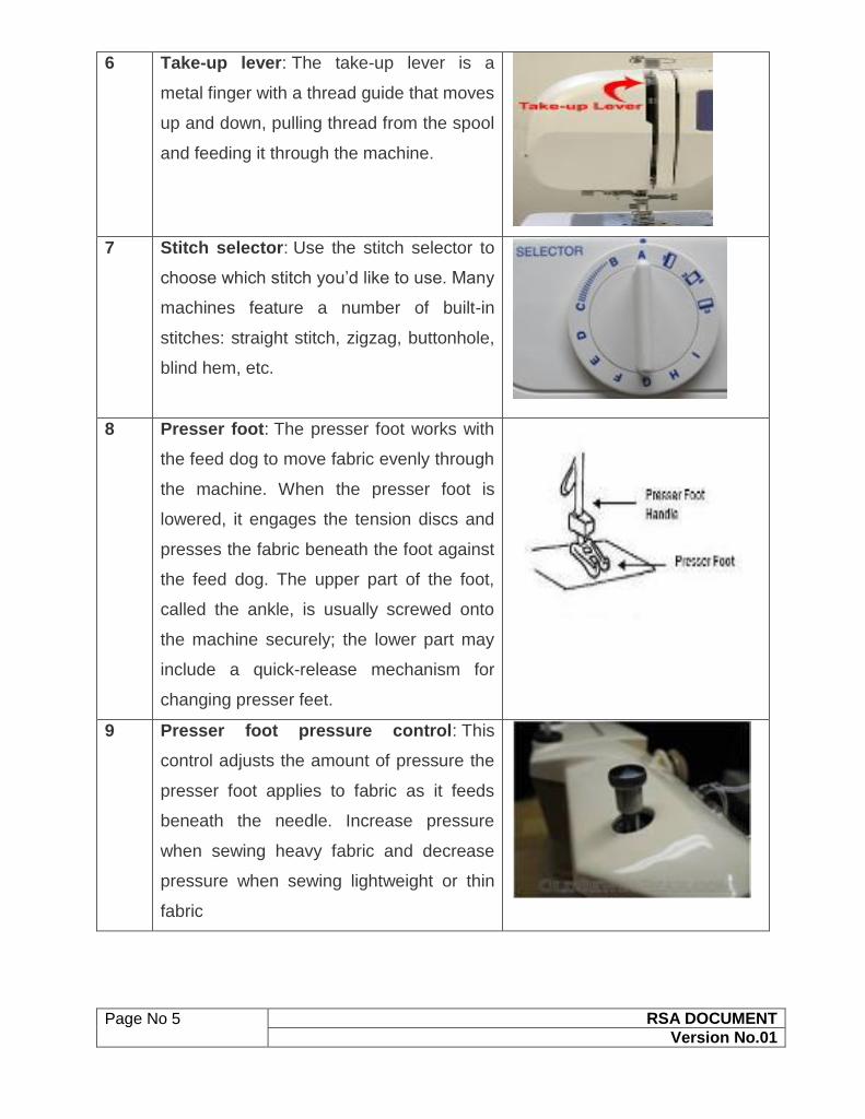
6 4. Take-up lever: The take-up lever is a
metal finger with a thread guide that moves
up and down, pulling thread from the spool
and feeding it through the machine.
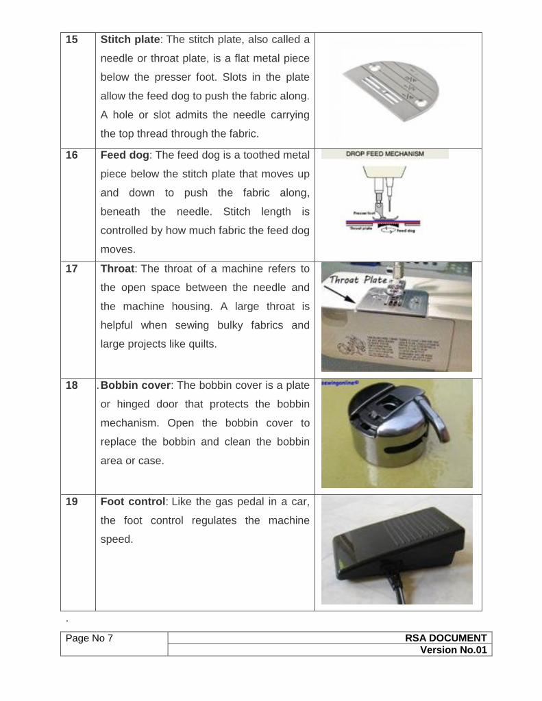
7 5. Stitch selector: Use the stitch selector to
choose which stitch you’d like to use. Many
machines feature a number of built-in
stitches: straight stitch, zigzag, buttonhole,
blind hem, etc.
8 6. Presser foot: The presser foot works with
the feed dog to move fabric evenly through
the machine. When the presser foot is
lowered, it engages the tension discs and
presses the fabric beneath the foot against
the feed dog. The upper part of the foot,
called the ankle, is usually screwed onto
the machine securely; the lower part may
include a quick-release mechanism for
changing presser feet.
9 Presser foot pressure control: This
control adjusts the amount of pressure the
presser foot applies to fabric as it feeds
beneath the needle. Increase pressure
when sewing heavy fabric and decrease
pressure when sewing lightweight or thin
fabric

Page No 6 RSA DOCUMENT
Version No.01
10 7. Presser foot lifter: This lever, located
above the presser foot at the back or side
of the machine, raises and lowers the
presser foot. When the presser foot is
lifted, the tension discs are disengaged,
and the fabric will not feed through the
machine.
11 8. Needle: The needle carries the upper
thread through the fabric to create a stitch.
Specialty needles are available for specific
stitching needs.
12 9. Needle threader: Some machines have
built-in needle threaders. Threaders have a
tiny hook that swings through the needle
eye catches the thread, and pulls it back
through the eye when the threader is
released.
13 Thread cutter: Some machines have a
built-in thread cutter near the needle area.
To use the cutter, raise the presser foot
and remove the stitched piece from the
machine. Pull both the threads over the
cutter’s shielded blade to cut them.
14 10. Needle clamp screw: Tighten and loosen
this screw to release or secure the needle
in place.
Page No 7 RSA DOCUMENT
Version No.01
15 Stitch plate: The stitch plate, also called a
needle or throat plate, is a flat metal piece
below the presser foot. Slots in the plate
allow the feed dog to push the fabric along.
A hole or slot admits the needle carrying
the top thread through the fabric.
16 Feed dog: The feed dog is a toothed metal
piece below the stitch plate that moves up
and down to push the fabric along,
beneath the needle. Stitch length is
controlled by how much fabric the feed dog
moves.
17 Throat: The throat of a machine refers to
the open space between the needle and
the machine housing. A large throat is
helpful when sewing bulky fabrics and
large projects like quilts.
18 11. Bobbin cover: The bobbin cover is a plate
or hinged door that protects the bobbin
mechanism. Open the bobbin cover to
replace the bobbin and clean the bobbin
area or case.
19 Foot control: Like the gas pedal in a car,
the foot control regulates the machine
speed.
.

Page No 8 RSA DOCUMENT
Version No.01
4. DIFFERENT TYPES OF SEWING MACHINES WITH TECHNICAL
DETAILS
MACHINE INTRODUCTION
Following is the list of Sewing machines which will be introduced in the next pages.
(It is advised to the trainers to demonstrate the concepts in the machine room only.)
1 SNLS machine
2 Over lock (all type)
3 Flat lock machine
4 Feed of the arm machine
5 Bartack machine
6 Button stitch machine
7 Button hole machine

Page No 9 RSA DOCUMENT
Version No.01
SINGLE NEEDLE LOCK STITCH MACHINE (SNLS)
The Single Needle Lock Stitch Machine is the most popular and versatile sewing
machine in the industry. It is designed to produce consistent results in sample and
production rooms. The Lockstitch forms precise and secured straight stitches on the
top and the underside of the fabric as the needle thread and the bobbin thread lock
(each other each time the needle passes through the fabric).

Page No 10 RSA DOCUMENT
Version No.01
Industrial SNLS Sewing Machine
SEWING MACHINE AND ITS PARTS
Thread Presser feet
control Thread
Tension Disc Thread
Needle Stitch
Dial
Take up lever
Thread
spring
tension
Throat Plate
Hand
Back tack
lever

Page No 11 RSA DOCUMENT
Version No.01
10. TECHNICAL ADJUSTMENT OF SNLS MACHINE
Technical adjustments which are to be taught while dealing with SNLS machines are
given below. Trainers should keep the following points in mind during the session of
SNLS machine.
1. First demonstrate the adjustment then ask trainee to practice on the machine.
2. Use the Instructional manual given by the machinery supplier during Session
3. Make sure, all the trainees are able to understand the Instructional manual.
Technical adjustments of SNLS machine
1. Basic Machine Practice (Loop Exercise)
2. Technical Specification
3. Installation of needle
4. Needle bar Height adjustment
5. Hook Set Timing
6. Feed Dog adjustment and alignment
7. Feed Dog Eccentric cam Adjustment
8. Pressure foot to Pressure adjustment
11. TECHNICAL ADJUSTMENT OF DNLS MACHINE
Technical adjustments which are to be taught while dealing with DNLS machines are
given below. Trainers should keep the following points in mind during the session of
DNLS machine
1. First demonstrate the adjustment then ask trainee to practice on the machine.
2. Use the Instructional manual given by the machinery supplier during Session
3. Make sure, all the trainees are able to understand the Instructional manual.
Technical adjustments of DNLS machine
1. Basic Machine Practice (Loop Exercise)
2. Technical Specification
3. Installation of needle
Page No 12 RSA DOCUMENT
Version No.01
4. Needle bar Height adjustment
5. Hook Set Timing
6. Feed timing Cam adjustment
7. Sprocket belt adjustment and change
8. Feed Dog adjustment and
9. Feed Dog alignment
10. Thread adjustment
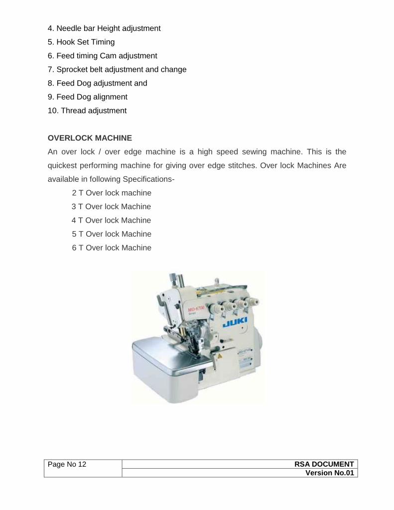
OVERLOCK MACHINE
An over lock / over edge machine is a high speed sewing machine. This is the
quickest performing machine for giving over edge stitches. Over lock Machines Are
available in following Specifications-
2 T Over lock machine
3 T Over lock Machine
4 T Over lock Machine
5 T Over lock Machine
6 T Over lock Machine

Page No 13 RSA DOCUMENT
Version No.01
Sr.No. Machine Name No. Of Threads
1 2 T Overlock Machine 1 1
2 3 T Overlock Machine 1 2
3 4 T Overlock Machine 2 2
4 5 T Overlock Machine 2 3
5 6 T Overlock Machine 3 3
12. TECHNICAL ADJUSTMENT OF OVERLOCK MACHINE
Technical adjustments which are to be taught while dealing with OVERLOCK
machines are given below. Trainers should keep the following points in mind during
the session of OVERLOCK machine
1. First demonstrate the adjustment then ask trainee to practice on the machine.
2. Use the Instructional manual given by the machinery supplier during Session
3. Make sure, all the trainees are able to understand the Instructional manual.
4. Practice of sewing on machine is also necessary.
Technical adjustments of OVERLOCK machine
1. Basic Machine Practice
2. Technical Specification
3. Installation of needle
4. Needle bar Height adjustment
5. Needle to lower looper timing
6. Upper Looper Timing
7. Chain looper timing (Safety Stitch)
8. Upper Knife Adjustment
9. Lower Knife adjustment
10. Feed Dog Height adjustment
11. Cam Timing
12. Thread Adjustment
Page No 14 RSA DOCUMENT
Version No.01
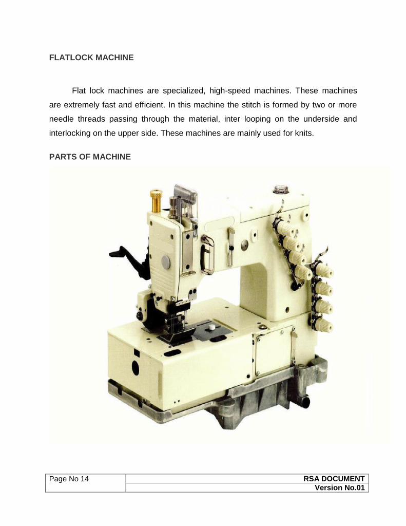
FLATLOCK MACHINE
Flat lock machines are specialized, high-speed machines. These machines
are extremely fast and efficient. In this machine the stitch is formed by two or more
needle threads passing through the material, inter looping on the underside and
interlocking on the upper side. These machines are mainly used for knits.
PARTS OF MACHINE

Page No 15 RSA DOCUMENT
Version No.01
13. TECHNICAL ADJUSTMENT OF FLATLOCK MACHINE
Technical adjustments which are to be taught while dealing with FLATLOCK
machines are given below. Trainers should keep the following points in mind during
the session of FLATLOCK machine.
1. First demonstrate the adjustment then ask trainee to practice on the machine.
2. Use the Instructional manual given by the machinery supplier during Session
3. Make sure, all the trainees are able to understand the Instructional manual.
4. Practice of sewing on machine is also necessary.
Technical adjustments of Flatlock machine
1. Basic Machine Practice
2. Technical Specification
3. Installation of needle
4. Needle bar Height adjustment
5. Main looper timing
6. Spreader Looper Adjustment
7. Stitch Length Adjustment
8. Feed Dog Height adjustment
9. Cam Timing (Thread)
10. Needle and looper guard adjustment

Page No 16 RSA DOCUMENT
Version No.01
FEED OF THE ARM MACHINE:
This machine is largely used for attaching sleeves and for making complex circular stitches
while attaching different parts of the garment
PARTS OF MACHINE
PARTS NAME –
1. Machine pulley
2 Front cover
3Presser foot
4. Needle bar
5.Upper thread guide
6. Lapper
SAFETY DEVICE –
1.Thread Take up cover
2.Finger guard
3.Pulley Cover

Page No 17 RSA DOCUMENT
Version No.01
14. TECHNICAL ADJUSTMENT OF FEED OF THE ARM
MACHINE
Technical adjustments which are to be taught while dealing with
Feed of Arm machines are given below. Trainers should keep the
following points in mind during the session of Feed of arm
machine
1. First demonstrate the adjustment then ask trainee to practice on
the machine.
2. Use the Instructional manual given by the machinery supplier
during Session
3. Make sure, all the trainees are able to understand the
Instructional manual.
4. Practice of sewing on machine is also necessary.
Technical adjustments of Feed of arm machine
machine –
1. Basic Machine Practice
2. Technical Specification
3. Installation of needle
4. Needle bar Height adjustment
5. Main looper timing
6. Puller adjustment
7. Needle Guard Adjustment
8. Looper Guard adjustment
9. Feed Dog height adjustment
10. Stitch Length Adjustment (Threading adjustment)

Page No 18 RSA DOCUMENT
Version No.01
BUTTON HOLE MACHINE
This machine is used for sewing buttons in the garment.
PARTS OF MACHINE

Page No 19 RSA DOCUMENT
Version No.01
17. TECHNICAL ADJUSTMENT OF BUTTON HOLE MACHINE
Technical adjustments which are to be taught while dealing with Button Hole
machines are given below. Trainers should keep the following points in mind during
the session of Button Hole machine
1. First demonstrate the adjustment then ask trainee to practice on the machine.
2. Use the Instructional manual given by the machinery supplier during Session
3. Make sure, all the trainees are able to understand the Instructional manual.
4. Practice of sewing on machine is also necessary.
Technical adjustments of Button Hole machine -
1. Basic Machine Practice
2. Technical Specification
3. Installation of needle
4. Needle Bar height adjustment
5. Hook Set Timing clearance
6. Thread trimming or scissors timing adjustment
7. Knife Adjustment and change
8. Panel Programming
18. TECHNICAL ADJUSTMENT OF BLIND HEM MACHINE
Technical adjustments which are to be taught while dealing with Blind Hem machines
are given below. Trainers should keep the following points in mind during the session
of Blind Hem machine.
1. First Demonstrate the adjustment then ask trainee to practice on the machine.
2. Use the Instructional manual given by the machinery supplier during Session
3. Make sure, all the trainees are able to understand the Instructional manual.
4. Practice of sewing on machine is also necessary.
Technical adjustments of Blind Hem machine –
1. Basic Machine Practice
2. Technical Specifications
3. Looper timing adjustment
4. Stitch Length Adjustment
Page No 20 RSA DOCUMENT
Version No.01
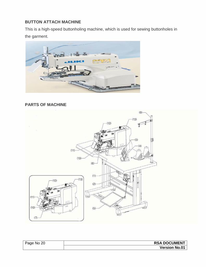
BUTTON ATTACH MACHINE
This is a high-speed buttonholing machine, which is used for sewing buttonholes in
the garment.
PARTS OF MACHINE

Page No 21 RSA DOCUMENT
Version No.01
Name of the various parts
1. Power Switch
2. Control box
3. SD card Slot
4. Operation Panel
5. Foot Switch
6. Work Clamp
7. Button Clamp
8. Pulley
9. Cotton Stand
SAFETY DEVICES
1. Finger Guard
2. Eye Guard
3. Threads take Up Cover
4. Rear Cover
5. Side Cover
6. DT Solenoid Cover
16. TECHNICAL ADJUSTMENT OF BUTTON ATTACH MACHINE
Technical adjustments which are to be taught while dealing with Button Stitch
machines are given below. Trainers should keep the following points in mind during
the session of Button Stitch machine.
1. First demonstrate the adjustment then ask trainee to practice on the machine.
2. Use the Instructional manual given by the machinery supplier during Session
3. Make sure, all the trainees are able to understand the Instructional manual.
4. Practice of sewing on machine is also necessary.

Page No 22 RSA DOCUMENT
Version No.01
Technical adjustments of Button Attach machine –
1. Basic Machine Practice
2. Technical Specification
3. Installation of needle
4. Button centre adjustment
5. Work Clamp adjustment
6. Needle Bar height adjustment
7. Hook Set Timing
8. Thread trimming (By moving and fix knife) Adjustment
9. Panel Programming
BARTACK MACHINE –
This machine is used for giving secure Bartack stitches.
PARTS OF BARTACK MACHINE

Page No 23 RSA DOCUMENT
Version No.01
15. TECHNICAL ADJUSTMENT OF BARTACK MACHINE
Technical adjustments which are to be taught while dealing with Bartack machines
are given below. Trainers should keep the following points in mind during the session
of Bartack machine.
1. First demonstrate the adjustment then ask trainee to practice on the machine.
2. Use the Instructional manual given by the machinery supplier during Session
3. Make sure, all the trainees are able to understand the Instructional manual.
4. Practice of sewing on machine is also necessary.
Technical adjustments of Bartack machine
1. Basic Machine Practice
2. Technical Specification
3. Installation of needle
4. Needle Bar height adjustment
5. Stitch length adjustment
6. Hook Set Timing
7. Thread trimming (By moving and fix knife) Adjustment
8. Panel Programming
Page No 24 RSA DOCUMENT
Version No.01
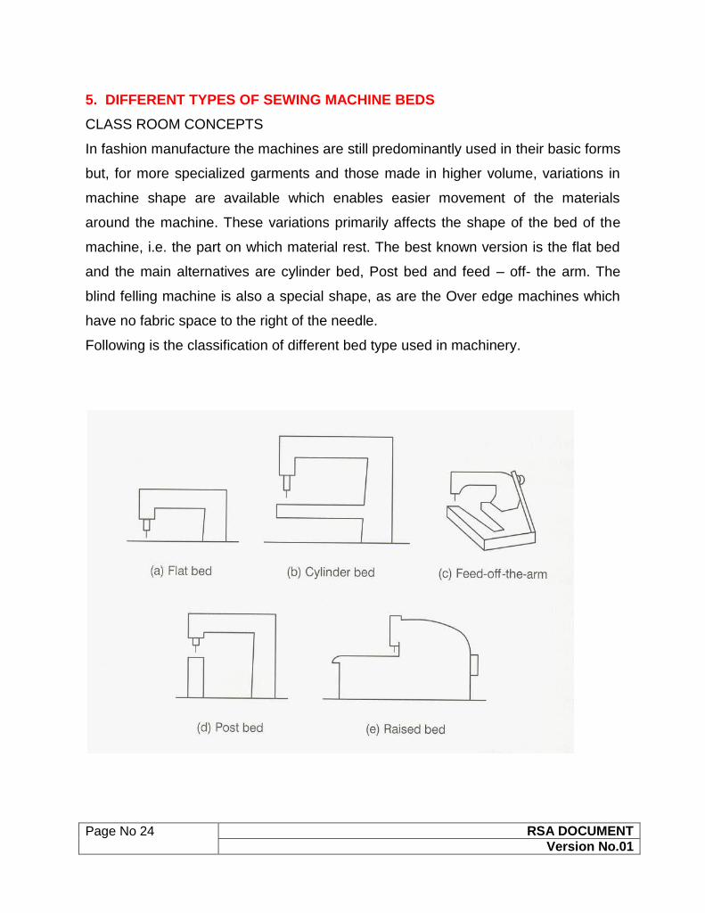
5. DIFFERENT TYPES OF SEWING MACHINE BEDS
CLASS ROOM CONCEPTS
In fashion manufacture the machines are still predominantly used in their basic forms
but, for more specialized garments and those made in higher volume, variations in
machine shape are available which enables easier movement of the materials
around the machine. These variations primarily affects the shape of the bed of the
machine, i.e. the part on which material rest. The best known version is the flat bed
and the main alternatives are cylinder bed, Post bed and feed – off- the arm. The
blind felling machine is also a special shape, as are the Over edge machines which
have no fabric space to the right of the needle.
Following is the classification of different bed type used in machinery.

Page No 25 RSA DOCUMENT
Version No.01
1. FLAT BED
The flat bed is used in the majority of sewing where a large and open garment part
can easily be handled past he needle. It provides a suitable surface for all flat sewing
and also facilitates the use of markers to control the position of the garment parts.
For example, a patch pocket on a shirt front.
2. CYLINDRICAL BED
These beds are basically used where the parts to be sewn are small, curved or
otherwise awkward in shape.
3. POST BED
It has the same applications as cylindrical Bed.
4. FEED OF THE ARM
The feed-off-the-arm machine is used where a lapped seam has to be closed in such
a way that the garment part becomes a tube. They are common in jeans production
where the outside leg seam is normally the type known as lap-felled and it is joined
after the inside leg seam in the sequence of construction. The operator wraps the
part to be sewn around the machine bed and it is fed away from the operator, off the
end of the bed, as the operator sews.

Page No 26 RSA DOCUMENT
Version No.01
5. BLIND STITCH
This machine also consist a different type of machine bed which is shown in the
given picture. Example of Blind machine’s use is in the bottom hem of trousers and
sometimes on closing the curtains etc.
6. OVERLOCK M/C bed
Over edge machine also have a different type of machine bed (See picture)
which have no fabric space to the right of the needle.
Page No 27 RSA DOCUMENT
Version No.01
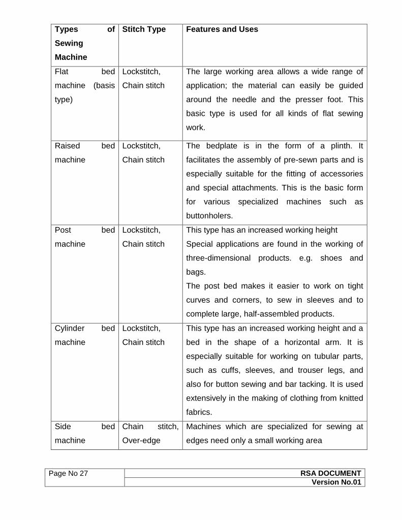
Types of
Sewing
Machine
Stitch Type Features and Uses
Flat bed
machine (basis
type)
Lockstitch,
Chain stitch
The large working area allows a wide range of
application; the material can easily be guided
around the needle and the presser foot. This
basic type is used for all kinds of flat sewing
work.
Raised bed
machine
Lockstitch,
Chain stitch
The bedplate is in the form of a plinth. It
facilitates the assembly of pre-sewn parts and is
especially suitable for the fitting of accessories
and special attachments. This is the basic form
for various specialized machines such as
buttonholers.
Post bed
machine
Lockstitch,
Chain stitch
This type has an increased working height
Special applications are found in the working of
three-dimensional products. e.g. shoes and
bags.
The post bed makes it easier to work on tight
curves and corners, to sew in sleeves and to
complete large, half-assembled products.
Cylinder bed
machine
Lockstitch,
Chain stitch
This type has an increased working height and a
bed in the shape of a horizontal arm. It is
especially suitable for working on tubular parts,
such as cuffs, sleeves, and trouser legs, and
also for button sewing and bar tacking. It is used
extensively in the making of clothing from knitted
fabrics.
Side bed
machine
Chain stitch,
Over-edge
Machines which are specialized for sewing at
edges need only a small working area

Page No 28 RSA DOCUMENT
Version No.01
6. DIFFERENT TYPES OF SEWING MACHINE BELTS
CLASS ROOM CONCEPTS
A belt is a loop of flexible material used to link two or more rotating shafts
mechanically. Belts may be used as a source of motion, to power efficiently, or to
track relative movement. Belts are looped over pulleys. In a two pulley system, the
belt can either drive the pulleys in the same direction, or the belt may be crossed, so
that the direction of the shafts is opposite. As a source of motion, a conveyor belt is
one application where the belt is adapted to continually carry a load between two
points
Belts are the cheapest utility for power transmission between shafts that may not be
axially aligned. Power transmission is achieved by specially designed belts and
pulleys.
Pros and cons
Belt drive, moreover, is simple, inexpensive, and does not require axially aligned
shafts. It helps protect the machinery from overload and jam, and it isolates noise
and vibration. Load fluctuations are shock-absorbed (cushioned). They need no
lubrication and require minimal maintenance. They have high efficiency (90-98%,
usually 95%), high tolerance for misalignment, and are inexpensive if the shafts are
far apart. Clutch action is activated by releasing belt tension. Different speeds can be
obtained by step or tapered pulleys.
The angular-velocity ratio may not be constant or equal to that of
the pulley diameters, due to slip and stretch. However, this problem has been largely
solved by the use of toothed belts. Adjustment of center distance or addition of an
idler pulley is crucial to compensate for wear and stretch.
Following are the various types of Belts which are widely used
1. FLAT BELT :
The drive belt: used to transfer power from the engine's flywheel. Here shown driving
a threshing machine.

Page No 29 RSA DOCUMENT
Version No.01
Flat belts were used early in line shafting to transmit power in
factories. It is a simple system of power transmission that was well suited for its day.
It delivered high power for high speeds (500 hp for 10,000 ft/min), in cases of wide
belts and large pulleys. These drives are bulky, requiring high tension leading to high
loads, so vee belts have mainly replaced the flatbelts except when high speed
is needed over power.
ROUND BELTS –
Round belts are a circular cross section belt designed to run in a pulley with a
circular (or near circular) groove. They are for use in low torque situations and may
be purchased in various lengths or cut to length and joined, either by a staple, gluing
or welding (in few case).
Early sewing machines utilized a leather belt, joined either by a metal staple
or glued, to a great effect.
VEE BELTS –
Vee belts (also known as V-belt or wedge rope) solved the slippage and alignment
problem. It is now the basic belt for power transmission. They provide the best
combination of traction, speed of movement, load of the bearings, and long service
life. They are generally endless, and their general cross-section shape is trapezoidal.
The "V" shape of the belt tracks in a mating groove in the pulley (or sheave), with the
result that the belt cannot slip off. The belt also tends to wedge into the groove as
the load increases — the greater the load, the greater the wedging action —
improving torque transmission and making the V-belt an effective solution, needing
less width and tension than flat belts. V-belts need larger pulleys for their larger
thickness than flat belts. They can be supplied at various fixed lengths or as a
segmented section, where the segments are linked (spliced) to form a belt of the
Page No 30 RSA DOCUMENT
Version No.01
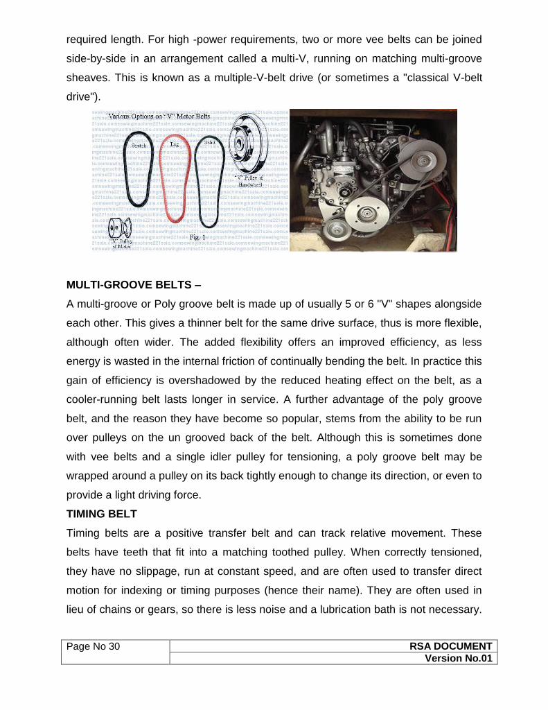
required length. For high -power requirements, two or more vee belts can be joined
side-by-side in an arrangement called a multi-V, running on matching multi-groove
sheaves. This is known as a multiple-V-belt drive (or sometimes a "classical V-belt
drive").
MULTI-GROOVE BELTS –
A multi-groove or Poly groove belt is made up of usually 5 or 6 "V" shapes alongside
each other. This gives a thinner belt for the same drive surface, thus is more flexible,
although often wider. The added flexibility offers an improved efficiency, as less
energy is wasted in the internal friction of continually bending the belt. In practice this
gain of efficiency is overshadowed by the reduced heating effect on the belt, as a
cooler-running belt lasts longer in service. A further advantage of the poly groove
belt, and the reason they have become so popular, stems from the ability to be run
over pulleys on the un grooved back of the belt. Although this is sometimes done
with vee belts and a single idler pulley for tensioning, a poly groove belt may be
wrapped around a pulley on its back tightly enough to change its direction, or even to
provide a light driving force.
TIMING BELT
Timing belts are a positive transfer belt and can track relative movement. These
belts have teeth that fit into a matching toothed pulley. When correctly tensioned,
they have no slippage, run at constant speed, and are often used to transfer direct
motion for indexing or timing purposes (hence their name). They are often used in
lieu of chains or gears, so there is less noise and a lubrication bath is not necessary.

Page No 31 RSA DOCUMENT
Version No.01
Camshafts of automobiles, miniature timing systems, and stepper motors often
utilize these belts.
Timing belts need the least tension of all belts, and are among the most
efficient. They can bear up to 200 hp (150 kW) at speeds of 16,000 ft/min. Timing
belts with a helical offset tooth design are available. The helical offset tooth design
forms a chevron pattern and causes the teeth to engage progressively. The chevron
pattern design is self aligning. The chevron pattern design does not make the noise
that some timing belts make at idiosyncratic speeds, and is more efficient at
transferring power (up to 98%).
Disadvantages include a relatively high purchase cost, the need for specially
fabricated toothed pulleys, less protection from overloading and jamming, and the
lack of clutch action.

Page No 32 RSA DOCUMENT
Version No.01
7. VARIOUS TYPES OF NEEDLES USED FOR SEWING DIFFERENT FABRICS
Select the type of needle based on the textile construction (i.e knit vs woven), and
the needle size is determined by the thickness of the thread and the weight of the
fabric used for sewing.
There are two needle sizing system :American and European. American Needle
sizes range from 8 to 19, and European sizes range from 60 to 120. Larger the
number, the larger the blade of the needle.
Commonly used needles and their uses as below:-

Page No 33 RSA DOCUMENT
Version No.01
Needle Fabric
Uses
Sizes Description
Ball-point
Knits 70/10 –
100/16
This needle has a medium tip that is a
slightly more rounded than a universal
needle and passes between the fabric
threads instead of piercing them. Ball-point
needles ensure more even stitches on
coarse and heavy knits and won’t damage
spandex, interlocks and other knits that snag
or run easily.
Sharp/
Microtex
Finely
woven
fabrics
60/8 –
90/14
These needles feature a narrow shaft and
sharper point to pierce the threads of woven
fabrics. Use for stitching smooth, finely
woven fabrics, such as silk, chintz,
lightweight faux suede and microfiber
fabrics. Because these needles enable
perfectly straight stitching, they’re also ideal
for heirloom stitching, topstitching, pintucks
and edge stitching.
Universal Knits or
woven
60/8 –
120/19
Point is very slightly rounded for use on
knits, but sharp enough to pierce woven
fabrics. These needles are available in the
widest size range. Use when stitching
Synthetic or natural woven and knits.
Denim/
Jeans
Heavy
wovens
and
denims
70/10 –
110/18
These needles have a thick, strong shaft
and a very sharp point. They are used for
stitching denim, canvas, duck and other
heavy, tightly woven fabrics. They are also
ideal for stitching through multiple fabric
layers without breaking.
Page No 34 RSA DOCUMENT
Version No.01
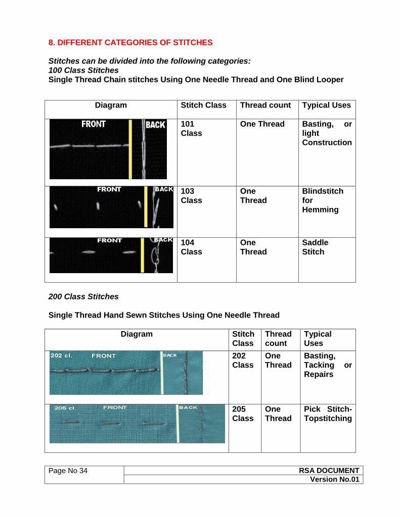
8. DIFFERENT CATEGORIES OF STITCHES Stitches can be divided into the following categories: 100 Class Stitches Single Thread Chain stitches Using One Needle Thread and One Blind Looper
Diagram Stitch Class
Thread count Typical Uses
101 Class
One Thread
Basting, or light Construction
103 Class
One Thread
Blindstitch for Hemming
104 Class
One Thread
Saddle Stitch
200 Class Stitches Single Thread Hand Sewn Stitches Using One Needle Thread
Diagram Stitch Class
Thread count
Typical Uses
202 Class
One Thread
Basting, Tacking or Repairs
205 Class
One Thread
Pick Stitch- Topstitching

Page No 35 RSA DOCUMENT
Version No.01
300 Class Stitches
Diagram Stitch Class
Thread count
Typical Uses
301 Class
Two Thread
Seaming Multiple
Plies
304 Class
Two Thread
Zig-Zag Stitch;
A Stretch Lockstitch
306 Class
Two Thread
Blind Stitch
315 Class
Two Thread
"Three Step Zig-Zag; stretch lockstitch with more Stretch
Page No 36 RSA DOCUMENT
Version No.01
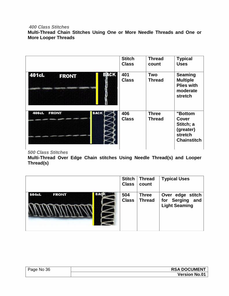
400 Class Stitches Multi-Thread Chain Stitches Using One or More Needle Threads and One or More Looper Threads
500 Class Stitches Multi-Thread Over Edge Chain stitches Using Needle Thread(s) and Looper Thread(s)
Stitch Class
Thread count
Typical Uses
401 Class
Two Thread
Seaming Multiple Plies with moderate stretch
406 Class
Three Thread
"Bottom Cover Stitch; a (greater) stretch Chainstitch
Stitch Class
Thread count
Typical Uses
504 Class
Three Thread
Over edge stitch for Serging and Light Seaming
Page No 37 RSA DOCUMENT
Version No.01
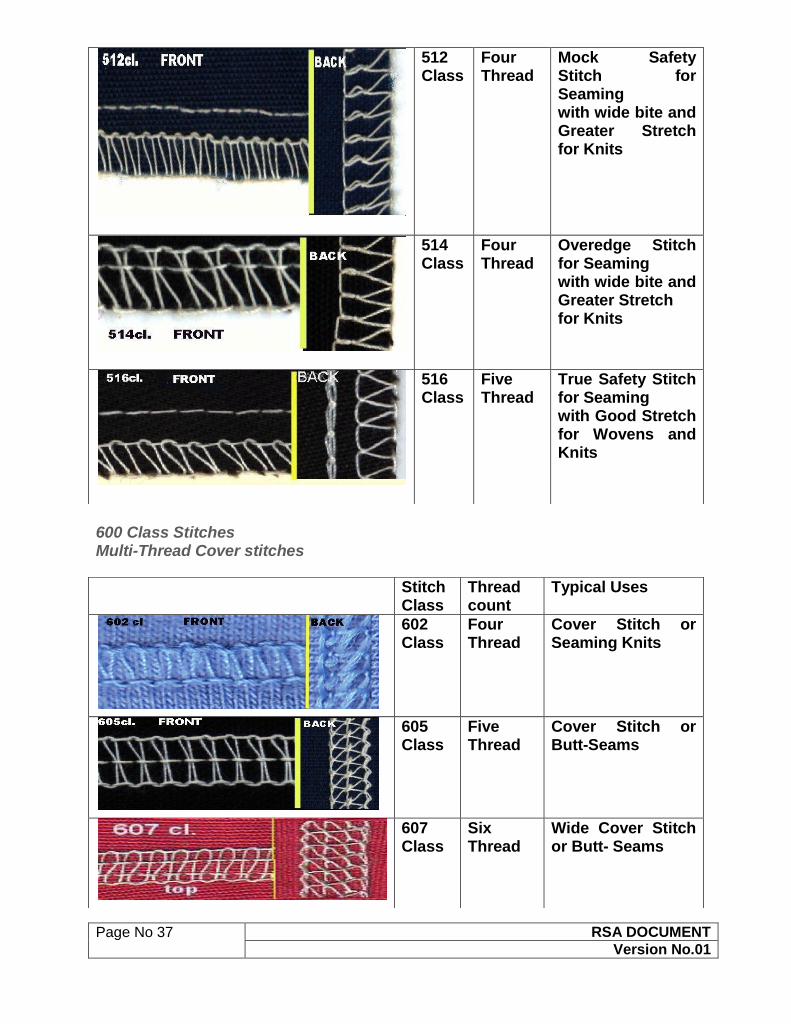
600 Class Stitches Multi-Thread Cover stitches
512 Class
Four Thread
Mock Safety Stitch for Seaming with wide bite and Greater Stretch for Knits
514 Class
Four Thread
Overedge Stitch for Seaming with wide bite and Greater Stretch for Knits
516 Class
Five Thread
True Safety Stitch for Seaming with Good Stretch for Wovens and Knits
Stitch Class
Thread count
Typical Uses
602 Class
Four Thread
Cover Stitch or Seaming Knits
605 Class
Five Thread
Cover Stitch or Butt-Seams
607 Class
Six Thread
Wide Cover Stitch or Butt- Seams

Page No 38 RSA DOCUMENT
Version No.01
9. LUBRICATION AND MAINTENANCE SYSTEMS CLASS ROOM CONCEPTS OILING SYSTEMS A. Manual oiling system it requires the operator to oil each point individually, and
on a regular (preferred 4-hour) basis.
B. Automatic oiling system it can supply all points of lubrication or can be com
binned with manual oiling. The oil in automatic systems can be distributed:
1. Through gravity,
2. Through splash,
3. Through wicking (such as cotton cord), or
4. Through pressure supplied by a pump.
All automatic oiling systems require the reservoir to be filled to a certain level with oil.
Wick fed systems range from small reservoirs (the wicking itself may serve as
reservoir) to more substantial cavities. The smaller the reservoir, the more often oil
will need to be added. Larger oil reservoirs of any system type may have marked
indicator levels, so that the operator can verify that enough oil is available in the
reservoir.
Pressure lubrication systems may have sight windows or bubbles. A flow or splash of
oil seen through these windows or bubbles will indicate that there is likely a good
pressure of oil in the system. Pressure systems may also have adjustment needles or
valves to control the flow of oil to critical points such as the hook race.
Any system can have an oil return mechanism to recirculate oil and to prevent build-
up of oil in pockets from which it may leak or overflow. The oil return mechanisms can
be gravity flow, wicking, or both. Pressure systems may also incorporate a suction
return, operated by the same pump that supplies oil pressure.
Lubrication is necessary for the sewing machine maintenance but at the same time
lubrication may be the cause of oil stains in a garment.

Page No 39 RSA DOCUMENT
Version No.01
To prevent the oil stains in a garment, an advance technology is used .On the basis
of that technology, we can divide the sewing machines into the following categories:-
1. Sewing Machine with Lubrication
2. Semi Dry head Sewing Machine
3. Dry Head Sewing Machine
SEWING MACHINE (SNLS) WITH LUBRICATION:
The needle bar and thread take-up components are lubricated with the minimum
required quantity of oil.
For the hook section, the standard method of lubrication is employed.
SEMI DRY HEAD SEWING MACHINE
With the advanced dry technology of enabling operation without being lubricated, a
frame which does not need lubrication has been developed. It is provided with not
only a high-speed sewing capability, but also a safety feature for preventing oil
stains.

Page No 40 RSA DOCUMENT
Version No.01
The needle bar and thread take-up components are not lubricated.
For the hook section, the standard method of lubrication is employed.
DRY HEAD SEWING MACHINE
As its designation indicates, the dry-head type machine ensures convenience of use
by totally preventing the oil from staining the material being sewn. The machine
wholly Contributes to the improved quality of finished products.
The section around the needle bar, the thread take-up lever and the hook are not
lubricated.

Page No 41 RSA DOCUMENT
Version No.01
MAINTENANCE
Maintenance is an Activity involved in maintaining something in “good working
order”. Widely it can be divided into two categories.
1. Corrective Maintenance
2. Preventive Maintenance
Corrective maintenance can be defined as the maintenance which is required when
an item has failed or worn out and to bring it back to working order. Corrective
maintenance is the most commonly used maintenance approach, but it has its
limitations. When an equipment fails, it often leads to downtime in production, and
sometimes damages other parts. In most cases, this is expensive also, if the
equipment needs to be replaced, the cost of replacing alone can be substantial.
Reliability of systems maintained by this type of maintenance is unknown and cannot
be measured. Therefore, corrective maintenance is carried out on all items where
the consequences of failure or wearing out are not significant (less important items)
and the cost of this maintenance is not greater than preventive maintenance.
Preventive Maintenance
Preventive maintenance is conducted to keep equipments working and/or extend the
life of the equipments. The primary goal of maintenance is to avoid or mitigate the
consequences of failure of equipment. Preventive Based Maintenance help to
prevent the failure before it actually occurs. It is designed to preserve and restore
equipments reliability by replacing worn components before they actually fail.
Preventive maintenance activities include partial or complete overhauls at specified
periods, oil changes, lubrication and so on. In addition, workers can record
equipment deterioration so they know when to replace or repair worn parts before
they cause system failure. The ideal preventive maintenance program would prevent
all equipment failure before it occurs. Following are the two examples of Preventive
maintenance Schedule which are commonly used in garment industry –
1st Plan talks about the, activities which have to be carried out on monthly basis and
2nd Plan talks about the quarterly (3 Months) basis.

Page No 42 RSA DOCUMENT
Version No.01
1. PREVENTATIVE MAINTENANCE SERVICES PLAN
MONTHLY CHECK
1. Thread stand clean & tight
2. Bobbin winder proper check
3. Feed dog check
4. Pressure foot check
5. Needle plate check
6. Needle screw check
7. V-belt check
8. Belt cover clean & tight
9. Pully & pully cover check
10. Hook set check
11. Oil level check properly & clean
12. Needle guard check
13. Moving knife check
14. Fix knife check
15. Foot rest check
16. Head rest pin check
17. Knee pad check
18. Padle mat check
19. Ubt machine proper working & check
20. Stand shoe check
21. Fabric guide check
22. Pedal chain check
23. Looper check
24. Waste tube check
25. Lower knife check
26. Upper knife check
27. Eye glass check
28. Table top condition check

Page No 43 RSA DOCUMENT
Version No.01
29. Machine condition check
30. Gauge set check
31. Top feed dog check
32. Gear bearing check
33. Pressure bar / regulator check
34. Bobin case check
35. Oil lubrication system check ing
2.PREVENTATIVE MAINTENANCE SERVICES PLAN
QUARTERLY CHECK
1. Oil change
2. Moto & control box clean by air pressure
3. All moving parts checking / replacement
4. Gear and bearing checking / replacement
10. DIFFERENT TYPES FEED MECHANISMS
CLASS ROOM CONCEPTS
DEFINITION
Besides the basic motion of needles, loppers and bobbins, the material being sewn
must move, so that each cycle of needle motion involves a different part of the
material. This motion is known as feed, and sewing machines have almost as many
ways of feeding material as they do of forming stitches. For general categories, we
have: drop feed, needle feed, walking foot, puller, and manual. Often, multiple types
of feed are used on the same machine. Besides these general categories, there are
also uncommon feed mechanisms used in specific applications like edge joining fur,
making seams on caps, and blind stitching.

Page No 44 RSA DOCUMENT
Version No.01
Functions of Feed dog
Makes the sewing product move per stitch.
Can change amount to move and forms stitches suitable for the sewing
product.
Stretch stitching or gathering stitching can be performed by means of feed
mechanism, and prevention of puckering, gathering, etc. can be performed.
DIFFERENT TYPES OF FEED
BOTTOM FEED
This is the most standard feed mechanism, which feeds material with a lower feed
dog only. Uneven material feeding is likely to occur because of bottom feed only.
However, sharp curve stitching can be easily performed and material handling is
easy.
NEEDLE FEED (BOTTOM FEED + NEEDLE FEED)
This is the feed mechanism in which needle bar moves in synchronization with
bottom feed. Feeding force is strong, and this type can feed material more precisely
than the aforementioned bottom feed type sewing machine. Uneven material feeding
is reduced, but, stitch shrinking due to thread tightness is likely to occur.

Page No 45 RSA DOCUMENT
Version No.01
DIFFERENTIAL FEED (FRONT BOTTOM FEED + REAR BOTTOM FEED)
This is the bottom feed mechanism, but feed dog is divided into front and rear. This
is the feed mechanism which is possible to intentionally stretch material or gather
material by changing feed amount of front feed dog and rear feed dog. This is
suitable for sewing elastic knit.
Differential feed ratio (e.g. JUKI over lock sewing machine, MO Series)
Gathering 1: 2 (Max. 1: 4)
Stretching 1: 0.7 (Max. 1: 0.6)
BOTTOM AND VARIABLE TOP FEED (BOTTOM FEED + TOP DIFFERENTIAL
FEED)
There is a feed dog on the top side in terms of bottom feed, and top feed amount can
be adjusted simultaneously together with adjustment of material feed from the
bottom side. Accordingly, this is the feed mechanism which is possible to prevent
sewing slippage, and to perform edging contracting or gathering.

Page No 46 RSA DOCUMENT
Version No.01
DIFFERENTIAL BOTTOM FEED AND VARIABLE TOP FEED
(Differential Feed + Top Differential Feed)
Bottom feed is differential feed, and top feed amount can be adjusted simultaneously
together with adjustment (stretching and gathering) of material feed from the bottom
side. Accordingly, this is the suitable mechanism which can give most suitable feed
amount to the upper and lower materials.
UNISON FEED (BOTTOM FEED + TOP FEED + NEEDLE FEED)
Feed force of this mechanism is most superior and this feed mechanism is largely
used for extra heavy-weight materials or the like.

Page No 47 RSA DOCUMENT
Version No.01
FEED WITH CLOTH PULLING ROLLER
Roller located in the rear of presser foot pulls materials and sewing is performed.
Uneven material feeding is reduced and working property is improved.
FIXED FEED
This is the feed mechanism to feed materials in a fixed state by holding materials
between lower plate and upper plate.
(Example: cycle machine and automatic machine)

Page No 48 RSA DOCUMENT
Version No.01
11. INTRODUCTION TO MOTORS
CLASS ROOM CONCEPTS
A motor is a machine designed to convert energy into useful mechanical motion.
Various types of motors are available in the market, but Sewing industry mostly uses
the electric motor. An electric motor uses electrical energy to produce mechanical
energy, usually through the interaction of magnetic fields and current-carrying
conductors.
Electric Motors can be classified into two categories:
1) AC Motors
2) DC Motors
AC motors are mostly used for the industrial Machinery.AC motors are also available
in various categories.AC induction motor is the most common technology used in the
Garment industry.
MOTOR
ELECTRIC MOTOR
DC MOTORS AC MOTORS
AC INDUCTION MOTOR
And AC MOTOR is used with the following drives to operate the sewing machine
Clutch (For clutch Motor)
SERVO (For Servo Motor)
Direct Drive

Page No 49 RSA DOCUMENT
Version No.01
We shall discuss about the motors which are used vitally in the Sewing machines.
1. Clutch Motor –
A clutch is a mechanical device which provides for the transmission of power from
one component (the driving member) to another (the driven member). Clutches are
useful in devices that have two rotating shafts. In these devices, one of the shafts is
typically driven by a motor or pulley, and the other shaft drives another device. The
clutch connects the two shafts so that they can be locked together and spins at the
same speed. Same Principle is used in the industrial sewing machine also.
2. Servo motor –
Servo is an automatic device that uses error sensing negative feedback to correct
the performance of a mechanism. The term correctly applies only to systems where
the feedback or error-correction signals help control mechanical position or other
parameters. Servo motor control system will replace the traditional electronic sewing
machine motor control and drive system to become a mainstream technology. More
and more extensive use of servo motor control system by garment processing
enterprises leads to cost saving, maintenance-free, low noise, and replaces the
traditional electronic motor control system. It becomes a sewing machine drive
system of the mainstream.

Page No 50 RSA DOCUMENT
Version No.01
Main Features of Servo Motor
Low noise, low vibration and low power consumption.
Linkable to PC.
Multi- Positioning mode.
Switching power supply system (160V ~ 280V.AC).
Powerful parameter system, easy adjustment and upgradeable.
Servo motor advantages
1. Energy saving & environmental protection
2. Saving more than 80%
3. Saving manpower by 20%
4. Small size, simple operation, easy maintenance, beautiful appearance
5. Long life
6. Starts, braking action smooth, little vibration
COMAPARISON OF SERVO AND CLUTCH MOTOR
NO More
features
Energy-saving servo motor Clutch Motor
1. Exterior Excellent, full of mechatronic
design concepts
Decentralized
structure, large pet
2. Labor
intensity
Low. Operation simple and
convenient, intelligent,
operator fatigue is not easy
High
3. Efficiency High. Output increase, the Low

Page No 51 RSA DOCUMENT
Version No.01
corresponding reduction
product processing fees
4. Vibration Low. Longer machine life,
improve the quality of work
improving the environment
Large
5. Noise Low. Longer machine life,
improve the working
Environment
Large
6. Service Low. Brushless servo motor,
maintenance-free
Clutch
replacement
7. Energy Once every province, electricity
(98% of non-running Power,
running power 26%)
Full operation
8. Network
configuration
Small. Start current, low total
power consumption
Large
9. saving Saving can be recovered within
a year, consolidated return on
investment for 6 months
High cost
3. Direct Drive –
A Direct drive mechanism is one that takes the power from a motor without any
reductions (such as a gearbox, chain and belt).
Advantages:
1. Increased efficiency: The power is not wasted in friction (from the belt, chain, etc,
and especially, gearboxes).
2. Reduced noise: Being a simpler device, a direct-drive mechanism has fewer parts
which could vibrate, and the overall noise emission of the system is usually lower.
3. Longer lifetime: Having fewer moving parts also means having fewer parts prone
to failure. Failures in other systems are usually produced by aging of the component
(such as a stretched belt), or stress.
4. No maintenance required for lubrication.

Page No 52 RSA DOCUMENT
Version No.01
12. ATTACHMENTS IN SEWING MACHINES (WORK AIDS)
Work aids are devices which are built into machines, added to them afterwards,
attached alongside or made use of in whatever ways a resourceful engineer can
devise to improve productivity, improve or maintain quality standards, reduce training
time and minimize fatigue for the operator.
Work Aids can be divided into the following categories –
1. Folder –
Folders are used, as their name implies, in situations where fabric must be
folded prior to sewing .They vary from the simple fold (which could be achieved by an
operator alone, though only slowly and perhaps untidily) to extremely complex
combinations of folders (which enable some to be achieved in a fraction of the
number of stages that it would take without the folders) and indeed enable some to
be achieved that would not be otherwise be possible at all.
Folders are frequently used on machines having more than one needle
(Note – Choose the folders for the “product” which are being manufactured in
the nearby Industry of the centre.)
2. Binder –
Many folders are available which
add further items of self-fabric or
other material to a garment and
of these, many come into the
category are known as Binder.
Fabric Edges are frequently
bound, either as a means of
edge neatening or to create a
decorative effect or both.
(Note -Use 28mm Piping folder for practice session

Page No 53 RSA DOCUMENT
Version No.01
3. Hemmer –
Folders which operate on a garment
part without any additional material
are knows as Hemmer.
(Note -Use Shirt Bottom Hemming folder for practice session)
4. Presser Foot and
Presser feet can be used as
specialized work aids, in
addition to their normal function
of holding the materials against
the feed dog, when the scale of
the situation is within the small
size of foot. The function of
edge guiding can be performed
in some circumstances by a
special presser foot called
compensating presser foot.

Page No 54 RSA DOCUMENT
Version No.01
5. Guides etc.
Guides are used where sewing must
take place in a certain position on a
garment.In their simplest form they are
edge guides, forming some kind of
physical barrier to the edges of the fabric
being joined together
Note -Use Variation of Straight and curved guide for practice session)

Page No 55 RSA DOCUMENT
Version No.01
13. STITCHING DEFECTS
Sewing defect can be classified as three groups:
Problems of stitch formation.
Problem of pucker.
Damage of fabric on seam line.
Problems of stitch formation: Slipped stitch: Stitches in the seam line are present in a regular manner. If the interloping or interlacing between top & bottom thread of stitch does not take place or missed is known as slipped stitch or skipped stitch. This is serious defect in case of chain stitch than lock stitch. The followings are the causes & remedies of slipped stitch formation.
No. Causes Remedies
01 If hook or looper & needle are not inserted in loop of thread in time.
Examine the setting & timing between needle & hook or looper. Placing the needle properly. More secure needle should be used.
02 Irregular thread tension on upper or lower loop.
The tension of the thread should again be adjusted.
03 Needle deflection. Needle to be changed.
04 If needle thread loop size is too small.
Needle size & thread size must be adjusted.
05 Flagging of fabrics during sewing.
The pressure of pressure foot must be adjusted accurately. The hole of throat plate & needle size must be adjusted.
06 If the sewing thread is not capable to form loop.
Thread to be changed
Page No 56 RSA DOCUMENT
Version No.01
Staggered stitch: If the stitches produced by needle are not parallel or become curvy to sewing line is known as staggered stitch.
No. Causes Remedies
01 Needle deflection. Increase the needle size Tapered needle should be used.
02 Due to wrong blunt needle point.
Needle to be changed.
03 Wrong adjustment of needle & thread size.
Needle size & thread size to be changed.
04 Deflected motion of feed dog.
Motion of feed dog to be adjusted.
05 If fabrics are not controlled properly in the feed mechanism.
The pressure of pressure foot must be adjusted accurately. Feed mechanism to be changed.
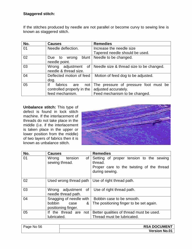
Unbalance stitch: This type of defect is found in lock stitch machine. If the interlacement of threads do not take place in the middle (i.e. if the interlacement is taken place in the upper or lower position from the middle) of two layers of fabrics then it is known as unbalance stitch.
No. Causes Remedies
01 Wrong tension of sewing thread.
Setting of proper tension to the sewing thread. Proper care to the twisting of the thread during sewing.
02 Used wrong thread path Use of right thread path.
03 Wrong adjustment of needle thread path.
Use of right thread path.
04 Snagging of needle with bobbin case & positioning finger.
Bobbin case to be smooth. The positioning finger to be set again.
05 If the thread are not lubricated.
Better qualities of thread must be used. Thread must be lubricated.

Page No 57 RSA DOCUMENT
Version No.01
Variable stitch density: Stitches per unit length should be uniform, If it is not then it is called variable stitch density. The main cause of variable stitch density is irregular feed of fabric due to insufficient pressure of pressure foot. The following are the cause & remedies of variable stitch density formation
No. Causes Remedies
01 Improper unwinding of thread from package during sewing.
The position of thread guide must be 2.5 times higher than the position of thread package. Also proper care should be kept to the thread package not to tiling
02 Twisting of needle thread in the bottom of the thread package.
Foam pad must be used to the bottom of the thread package.
03 Snarling of thread before tension disk.
Winding of more threads in the thread guide & to keep less tension to the tensioning disk.
04 Twisting of thread in the thread guide.
Proper threading of sewing thread during sewing.
05 More tension to the thread. The tension of thread should be less or use high strength threads.
06 Use of broken check spring. Check spring to be changed.
07 If the edge of the throat plate, hook point, needle guard, bobbin case, needle groove, needle eye & so on
The edges must be smooth & needle must be changed as needed.

Page No 58 RSA DOCUMENT
Version No.01
are sharpened.
08 Fraying of thread in the needle.
Fine thread must be used or use heavy needle.
09 Thread gets heated more High quality needle must be used. Needle lubricant must be used. Needle cooler must be used.
10 Hook gets heated more Lubricant must be available. Examine the distance between the needles & hook.
11 Use of low quality threads. Thread to be changed.
Frequent thread breakage: Frequent breakage of thread especially, when there needs to open out the sewing to solve the problem. The following are the causes & remedies of frequent thread breakage.

Page No 59 RSA DOCUMENT
Version No.01
No. Causes Remedies
01 Wrong winding of threads on to the bobbin.
Proper winding of threads on to the bobbin. Pre-wound bobbin may be used.
02 More tension to the bobbin threads or more rotating of bobbin.
The tension must be adjusted to the bobbin threads. Use of washer to prevent more rotation of bobbin.
03 If the edges bobbin case, looper eye & so on are more sharpened.
The edges to be smooth.
04 Wrong fitting of bobbin case. Examine the size & type of bobbin. Examine the damaging of bobbin case.
Broken Stitches: When stitches are broken during sewing is called broken stitch. Cause: Where the thread is being broken where one seam crosses another seam (ex: bar tacks on top of waistband stitching, seat seam on top of riser seam.)
Remedies:
Where the thread is being cut, use a large diameter thread on operations.
Make sure the proper stitch balance is being used.
Use needles with appropriate needle point.
At regular intervals on operations, change the needles where they occur frequently.
Problems of pucker: Puckering is a wrinkle appearance along a seam line in a smooth fabric. It is one of the frequently occurring defects. Puckering shows that as if there is too much fabric & not enough thread in the seam & as if the thread is drawing the seam in. This is

Page No 60 RSA DOCUMENT
Version No.01
the reason why sewing thread is often blamed for causing puckering though there are other factors as well as for promotion of puckering. They are given below: 1) Fabric structure. 2) Seam construction. 3) Needle size. 4) Material feeding problem. 5) Wrong thread tension & 6) Unsuitable thread.
Reasons of Puckering
Fabric dimensional instability. Extension of sewing thread. Sewing threads shrinkage. Structural jamming of fabric. Mismatched patterns. Variable or uneven stretch on fabric plies: Causes: There is a great possibility of occurring seam pucker in case of more plied of fabrics when sewing together.
Due to variable stitch on fabric plies they will not feed equally to sewing m/c & create seam pucker.
This type of pucker is seen for limitation of feed mechanism.
Remedies:
Taking proper care during sewing.
Using proper feed mechanism.
Fabric dimensional instability:
Causes: If the shrinkage of sewn fabric plies are not same or equal then Seam pucker will create after washing.
If the shrinkage percentage of area of two pieces of fabrics is more than 2, then seam pucker will occur after sewing the fabric together. Remedies:
Use suitable feed mechanism, Maintain shrinkage and take extra care during sewing.
Extension of sewing thread: Causes: If the tension on needle thread is higher than the under thread, then seam pucker will be produced or relaxed.

Page No 61 RSA DOCUMENT
Version No.01
Due to tension, the length of thread is extended slightly. When the fabric is displaced or descend from the machine after sewing, shrinkage of thread & fabric occurs due to their tendency of coming to original position.
If the shrinkage percentage of thread is higher than the fabric seam pucker happens. Remedies:
To give sufficient thread tension.
To maintain shrinkage.
Unraveling Seams: Cause: Generally occurs on 401 chain stitch seams where either the stitch has been broken or a skipped stitch has occurred. Unless the seam is re-stitched, this will cause seam failure. Remedies:
Ensuring Proper machine maintenance and machine adjustments.
Sewing operators to follow correct material handling techniques. Re-stitched Seams: Where there is a "splice" on the stitch line. The seam does not appear to be 1st quality merchandise, if this occurs on topstitching. Causes: Thread breaks or thread run-out during sewing. Cut or broken stitches during a subsequent treatment of the finished product (i.e., stone washing).
Remedies:
Use a better quality sewing thread and minimize sewing interruptions
Use higher performance thread specifically designed for that purpose.
Ensure sewing machine adjustments and proper machine maintenance.
Observe sewing operators for correct material handling techniques.

Page No 62 RSA DOCUMENT
Version No.01
Damage of fabric on seam line: A garment can be rejected due to damage of fabrics or yarn of fabrics in the seam line. This happens due to wrong needle selection or needle damage. The fabrics are damaged due to defective needle. But it may happen in case of new or fine needles. There are two types of fabric damaging are available given below:- 1) Mechanical damage: Damaging of fibres or yarns in the fabrics by needle is the entire defects of mechanical damage. The followings are the steps to be taken to keep the fabrics free from this type of defect: By using perfect size & shape of the needle & needle point without any defect.
By reducing the speed of sewing machine.
By using lubricant.
By testing sewability before sewing fabrics. 2) Needle heating damage: The damage of fabric due to friction occurring between the needle & fabrics. The resulting temperature due to friction in the needle is very high. The fabric can get damaged in that temperature. There is less damage in case of fabrics made from natural fibres. The following are the steps to be taken to keep the fabrics free from this type of defect: By reducing sewing speed, generation of heat to the needle will be less. But it affects production speed and does not suit for large production.
By changing needle Size & shape so that there is less generation of heat to the needle.
By sewing smaller length at higher speed.
By blowing cool air on the needle during sewing so that the temperature can be controlled.
By using lubricant to the needle.
By using Teflon coated needle. Defects occurring due to handling, for instance spoilage, staining etc.
Defects occurring due to oil mark.
Defects occurring due to dirty spot. Size Measurement Faults: During manufacturing of garments size of some parts are measured as per requirement. After assembling full garments also dimensions are measured to ensure that the dimension of garments is as per specifications. Faults occurring at this stage is can be reduced very much. During size measurement the parts which are measured are – 1) Chest 2) Waist 3) Shoulder 4)

Page No 63 RSA DOCUMENT
Version No.01
Sleeve length 5) Sleeve opening 6) Body length 7) Neck width 8) Front neck drop 9) Back neck drop 10) Collar Height 11) Arm hole 12) Placket length 13) Pocket length 14) Pocket width 15) Bottom part and 16) Hem opening etc., Garment Twist A rotation, usually lateral, between different panels of a garment resulting from the release of latent stresses during laundering of the woven or knitted fabric forming the garment. Torque or spirality may also be used to refer twist. Sewing thread shrinkage:
Causes: Due to variable shrinkage % of sewing thread & fabric, Seam pucker will create after washing or ironing.
Cotton threads develop puckering when wet or after wash.
Remedies:
To use synthetic thread.
It is good to know about the shrinkage % of fabric & thread before selection to sew.
Structural jamming of fabric:
Causes: When sewing is done by needle to densely woven fabrics or in which no. of warp & weft yarns are more in one inch, seam pucker happens due to shrinkage of fabric. Remedies:
By using finer thread & needle.
By minimising stitch density.
By cutting & sewing on bias angle.
By using chain stitch instead of lock stitch.
To change fabric (if necessary). Mismatched patterns:
Causes: Seam pucker will create when two different size of patterns are sewn together.
The designer is responsible for this. It can also occur due to wrong selection of patterns.
Remedies: Experienced pattern designer is needed. Change or rectify the pattern.

Page No 64 RSA DOCUMENT
Version No.01
14. SAFETY MEASURES:
The machine Mechanic working in factories, must follow the following points and
adopt safe working practices.
Disconnect the sewing machine by pulling out the plug from the wall outlet,
not by jerking the cord. Jerking the cord can cause the cord to become worn
or frayed.
Disconnect the plug from the wall outlet first then the plug from the machine.
Otherwise, electricity continues going through the cord and you could receive
an electrical shock.
Always unplug the machine from the electrical outlet when removing covers,
lubricating, or when making any other user servicing adjustments
Place pins, needles and tools in a container when not using them. Do not
leave them loosely on the table or on the floor.
Pins and needles should never be placed in your mouth.
When not in use, pointed tools should be left closed.
Handle sharp tools with the handle first.
When in doubt, ask the instructor.
Report any injuries or accidents immediately to the instructor. Also, Report a
breakage to a tool or m/c to the instructor.
Wipe up any oil spillage on the floor immediately to prevent anyone from
slipping. Keep aisles clear at all times.
Operate only the machines you have been trained to operate
Make only adjustments you have been trained to perform
When on duty wear low shoes & close-fitting clothing. Avoid loose fitting
sleeves, sweaters, jewellery, ties, and ribbons when operating the machine. If
your hair is long, tie it back.
Always practice proper posture to reduce fatigue, help prevent accidents and
increase efficiency.
Use both hands to raise & lower the machine head.