Table of Contents Section 24 - Schneider Electricstatic.schneider-electric.us/digest/17424.pdf ·...
22
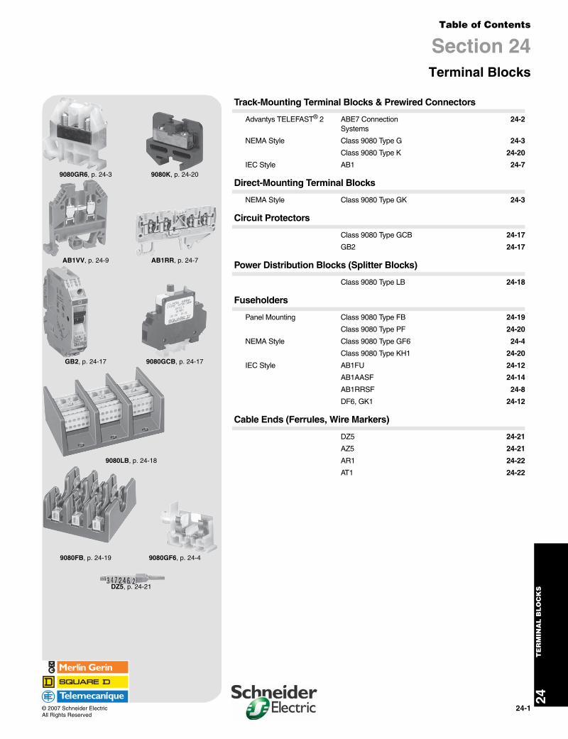
24-1 © 2007 Schneider Electric All Rights Reserved 24 TERMINAL BLOCKS Table of Contents Section 24 Terminal Blocks 9080GR6, p. 24-3 9080K, p. 24-20 AB1VV, p. 24-9 AB1RR, p. 24-7 GB2, p. 24-17 9080GCB, p. 24-17 9080LB, p. 24-18 9080FB, p. 24-19 9080GF6, p. 24-4 DZ5, p. 24-21 Track-Mounting Terminal Blocks & Prewired Connectors Advantys TELEFAST ® 2 ABE7 Connection Systems 24-2 NEMA Style Class 9080 Type G 24-3 Class 9080 Type K 24-20 IEC Style AB1 24-7 Direct-Mounting Terminal Blocks NEMA Style Class 9080 Type GK 24-3 Circuit Protectors Class 9080 Type GCB 24-17 GB2 24-17 Power Distribution Blocks (Splitter Blocks) Class 9080 Type LB 24-18 Fuseholders Panel Mounting Class 9080 Type FB 24-19 Class 9080 Type PF 24-20 NEMA Style Class 9080 Type GF6 24-4 Class 9080 Type KH1 24-20 IEC Style AB1FU 24-12 AB1AASF 24-14 AB1RRSF 24-8 DF6, GK1 24-12 Cable Ends (Ferrules, Wire Markers) DZ5 24-21 AZ5 24-21 AR1 24-22 AT1 24-22
-
Upload
truongtuyen -
Category
Documents
-
view
244 -
download
1
Transcript of Table of Contents Section 24 - Schneider Electricstatic.schneider-electric.us/digest/17424.pdf ·...
24-1© 2007 Schneider ElectricAll Rights Reserved
24T
ER
MIN
AL
BLO
CK
S
Table of Contents
Section 24Terminal Blocks
9080GR6, p. 24-3 9080K, p. 24-20
AB1VV, p. 24-9 AB1RR, p. 24-7
GB2, p. 24-17 9080GCB, p. 24-17
9080LB, p. 24-18
9080FB, p. 24-19 9080GF6, p. 24-4
DZ5, p. 24-21
Track-Mounting Terminal Blocks & Prewired Connectors
Advantys TELEFAST® 2 ABE7 Connection Systems
24-2
NEMA Style Class 9080 Type G 24-3
Class 9080 Type K 24-20
IEC Style AB1 24-7
Direct-Mounting Terminal Blocks
NEMA Style Class 9080 Type GK 24-3
Circuit Protectors
Class 9080 Type GCB 24-17
GB2 24-17
Power Distribution Blocks (Splitter Blocks)
Class 9080 Type LB 24-18
Fuseholders
Panel Mounting Class 9080 Type FB 24-19
Class 9080 Type PF 24-20
NEMA Style Class 9080 Type GF6 24-4
Class 9080 Type KH1 24-20
IEC Style AB1FU 24-12
AB1AASF 24-14
AB1RRSF 24-8
DF6, GK1 24-12
Cable Ends (Ferrules, Wire Markers)
DZ5 24-21
AZ5 24-21
AR1 24-22
AT1 24-22

www.us.schneider-electric.comFOR CURRENT INFORMATION
24T
ER
MIN
AL
BL
OC
KS
24-2 © 2007 Schneider ElectricAll Rights Reserved
Advantys TELEFAST® 2 Prewired Connection SystemRefer to Catalog 8501CT9801
The TELEFAST 2 system is a set of products for the rapid connection of I/O modules (24 Vdc discrete, analog and counters) to Various control circuit components. These components act as a substitute for screw terminal blocks, remotely locating and partly eliminating the single wire connections. The system connects only to channels with HE10 and SUB-D connectors, or to standard terminal blocks with a cabled connector.
Variations within the listing of modules include those with and without relays (electromechanical and solid state), analog and counter modules, and special function modules.
Pre-wired cables available allow you to connect directly to:
• Schneider Electric (Modicon® family)— TSX Premium™— TSX Micro— TSX Series 7— Twido— Quantum™— Compact— April S5000/7000— NUM1020/1060
• Siemens— S7 – 200/300/400— S5 – 95U to 155U
• Allen-Bradley— SLC500
In addition, other accessories include:
• I/O simulators• Continuity blocks• Label marking software• Splitter bases (16, 23, and 32 channels)• Mounting kits • Detachable terminal strips• Wiring pass-through connectors• Fuses
Advantys TELEFAST 2 Product Features
NOTE: Not all features available on all modules.
LEDs Indicating I/O State and Blown Fuse
Custom Labeling of Channels (cover face)and Wiring Diagram (under cover)
Blade Isolation Switches per
Channel
Test Point for 2.3 mm PlugFuse Protection for the Cable and Power Supply
Power Supply LED
Detachable Terminal Blocks
(Screw Terminations)
35 mmDIN-rail
Mounting
Fusing per Channel
Blade Isolation Switch on the 0 V terminal of the Power Supply

www.us.schneider-electric.comFOR CURRENT INFORMATION
24T
ER
MIN
AL
BLO
CK
S
© 2007 Schneider ElectricAll Rights Reserved
24-3
NEMA Style Terminal Blocks
Type GClass 9080 / Refer to Catalog 9080CT9601
a Orders must specify standard package quantity or multiples of that quantity.b These maximum current values assume the use of insulated copper conductors with 75oC temperature rating, and are calculated based on NEC Article
310, Table 310-16. In most cases this value is the maximum ampacity of that wire or combination of wires (as listed in the above table) which has the greatest current carrying capacity. The actual allowable current for a particular application depends on the number, size, insulation class, and other characteristics of the wires used. The lower of the UL and CSA ratings are shown.
c One end-barrier is required for each assembly of like blocks.d Terminals are tin plated, making them suitable for use with either copper or aluminum wire.
For Standard or Custom Assemblies . . . . . . . . . . . . . . . . . . . . . . . page 24-5For Mounting Track Accessories. . . . . . . . . . . . . . . . . . . . . . . . . . . page 24-6For DIN 3 track and end clamps . . . . . . . . . . . . . . . . . . . . . . . . . . page 24-16
Table 24.1: Selection Guide
Description MaximumVoltage
MaximumCurrentb
Blocks End BarrierscBlocks per ft
Max. Wire Combinations
Color Type $ Priceea.
Std. Packa Type $ Price
ea.Std.
PackaCopper Wire
(stranded or solid)
Solderless Box Lugfor #22 to #8 AWG wire.
Mounts on standard 9080GH track or 35 mm DIN 3 track.Fingersafe per DIN 57470.
600 V 60 A
Natural GR6
1.60 50
GM6B
0.52 10
34
1 #8 1 #10
1–3 #12 1–4 #14
1–4 #16 1–5 #18 1–8 #20 1–10 #22
Black GRB6 GMB6BBlue GRL6 GML6B
Green GRG6 GMG6B Gray GRE6 GME6B
Orange GRS6 GMS6B Red GRR6 GMR6B
Yellow GRY6 GMY6B Brown GRN6 GMN6B
Similar to a 9080GR6 except with a 9080GH91 banana test plug adapter installed.Fingersafe per DIN 57470. 600 V 60 A Natural GR6T 1.90 50 GM6B 0.52 10
Solderless Box Lugfor #22 to #10 AWG wire.
Can be mounted directly to a panel or can be mounted on 9080GH track.
600 V 40 A
Natural GK6
1.60 50 GK6B 0.62 50 34
1–4 #16 1 #10
1–2 #12 1–2 #14
1–4 #16 1–5 #18 1–8 #20 1–10 #22
Black GKB6Blue GKL6
Green GKG6Gray GKE6
Orange GKS6Red GKR6
Yellow GKY6
High DensitySolderless Box Lugfor #22 to #10 AWG wire.
Mounts on standard 9080GH track or 35 mm DIN 3 track.Fingersafe per DIN 57470.
600 V 30 A
Natural GM6
1.20 50
GM6B
0.52 10 51
1 #10 1 #12 1 #14
1–2 #16
1–2 #18 1–5 #20 1–8 #22 1–2 #16
Black GMB6 GMB6BBlue GML6 GML6B
Green GMG6 GMG6BGray GME6 GME6B
Orange GMS6 GMS6BRed GMR6 GMR6B
Yellow GMY6 GMY6BBrown GMN6 GMN6B
Solderless Box Lugfor #18 to #4 AWG wire.
Mounts on standard 9080GH track or 35 mm DIN 3 track. 600 V 85 A Natural GC6 3.30 50 GC6B 0.85 10 28
1 #4 1 #6
1–2 #8 1–4 #10
1–5 #12 1–6 #14 1–6 #16 1–8 #18
Solderless Box Lugfor #12 to #1/0 AWG wire.
Mounts on standard 9080GH track or 35 mm DIN 3 track. 600 V 170 A Natural GD6 6.70 10 GD6B 1.10 10 17
1 1/0 1 #1 1 #2
1–2 #4
1–3 #6 1–5 #8 1–6 #10 1–7 #12
Solderless Box Lugfor #6 AWG to 250 kcmil wire. d
Mounts on standard 9080GH track or 35 mm DIN 3 track. 600 V 255 A Natural GE6 18.00 10 None Required 10
1 250 kcmild1 4/0 1 3/0 1 2/0 1 1/0
1 #1 1 #2 1 #4 1 #6
FileCCN
E60616XCFR2
FileClass
LR621446228 01
CP5 Discount Schedule
www.us.schneider-electric.comFOR CURRENT INFORMATION
24T
ER
MIN
AL
BL
OC
KS
24-4 © 2007 Schneider ElectricAll Rights Reserved
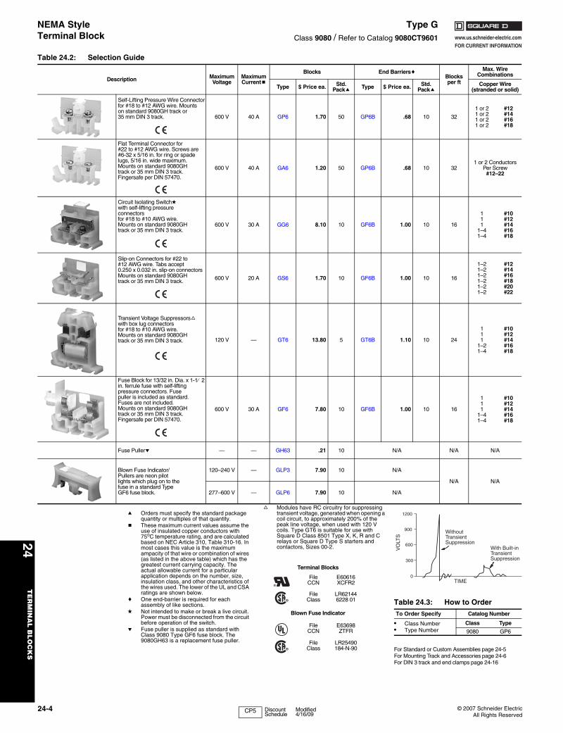
NEMA Style Terminal Block
Type GClass 9080 / Refer to Catalog 9080CT9601
a Orders must specify the standard package quantity or multiples of that quantity.
b These maximum current values assume the use of insulated copper conductors with 75oC temperature rating, and are calculated based on NEC Article 310, Table 310-16. In most cases this value is the maximum ampacity of that wire or combination of wires (as listed in the above table) which has the greatest current carrying capacity. The actual allowable current for a particular application depends on the number, size, insulation class, and other characteristics of the wires used. The lower of the UL and CSA ratings are shown below.
c One end-barrier is required for each assembly of like sections.
d Not intended to make or break a live circuit. Power must be disconnected from the circuit before operation of the switch.
e Fuse puller is supplied as standard with Class 9080 Type GF6 fuse block. The 9080GH63 is a replacement fuse puller.
f Modules have RC circuitry for suppressing transient voltage, generated when opening a coil circuit, to approximately 200% of the peak line voltage, when used with 120 V coils. Type GT6 is suitable for use with Square D Class 8501 Type X, K, R and C relays or Square D Type S starters and contactors, Sizes 00-2.
For Standard or Custom Assemblies page 24-5For Mounting Track and Accessories page 24-6For DIN 3 track and end clamps page 24-16
Table 24.2: Selection Guide
Description Maximum Voltage
Maximum Currentb
Blocks End BarrierscBlocksper ft
Max. Wire Combinations
Type $ Price ea. Std. Packa Type $ Price ea. Std.
PackaCopper Wire
(stranded or solid)
Self-Lifting Pressure Wire Connector for #18 to #12 AWG wire. Mounts on standard 9080GH track or 35 mm DIN 3 track. 600 V 40 A GP6 1.70 50 GP6B .68 10 32
1 or 21 or 21 or 21 or 2
#12 #14 #16 #18
Flat Terminal Connector for #22 to #12 AWG wire. Screws are #6-32 x 5/16 in. for ring or spade lugs, 5/16 in. wide maximum.Mounts on standard 9080GH track or 35 mm DIN 3 track.Fingersafe per DIN 57470.
600 V 40 A GA6 1.20 50 GP6B .68 10 321 or 2 Conductors
Per Screw#12–22
Circuit Isolating Switchdwith self-lifting pressureconnectorsfor #18 to #10 AWG wire.Mounts on standard 9080GH track or 35 mm DIN 3 track.
600 V 30 A GG6 8.10 10 GF6B 1.00 10 16
111
1–41–4
#10 #12 #14 #16 #18
Slip-on Connectors for #22 to #12 AWG wire. Tabs accept 0.250 x 0.032 in. slip-on connectorsMounts on standard 9080GH track or 35 mm DIN 3 track. 600 V 20 A GS6 1.70 10 GF6B 1.00 10 16
1–21–21–21–21–21–2
#12#14#16#18#20#22
Transient Voltage Suppressorsfwith box lug connectorsfor #18 to #10 AWG wire.Mounts on standard 9080GH track or 35 mm DIN 3 track. 120 V — GT6 13.80 5 GT6B 1.10 10 24
111
1–21–4
#10 #12 #14 #16 #18
Fuse Block for 13/32 in. Dia. x 1-1⁄ 2 in. ferrule fuse with self-liftingpressure connectors. Fusepuller is included as standard.Fuses are not included.Mounts on standard 9080GH track or 35 mm DIN 3 track.Fingersafe per DIN 57470.
600 V 30 A GF6 7.80 10 GF6B 1.00 10 16
111
1–41–4
#10 #12 #14 #16 #18
Fuse Pullere — — GH63 .21 10 N/A N/A N/A
Blown Fuse Indicator/Pullers are neon pilotlights which plug on to thefuse in a standard TypeGF6 fuse block.
120–240 V — GLP3 7.90 10 N/A
N/A N/A
277–600 V — GLP6 7.90 10 N/A
Terminal Blocks
FileCCN
E60616XCFR2
FileClass
LR621446228 01
Blown Fuse Indicator
FileCCN
E63698ZTFR
FileClass
LR25490184-N-90
Table 24.3: How to OrderTo Order Specify Catalog Number
• Class Number• Type Number
Class Type
9080 GP6
With Built-inTransientSuppression
WithoutTransientSuppression
TIME
VO
LTS
0
300
600
900
1200
CP5 Discount Schedule
Modified4/16/09
www.us.schneider-electric.comFOR CURRENT INFORMATION
24T
ER
MIN
AL
BLO
CK
S
© 2007 Schneider ElectricAll Rights Reserved
24-5
NEMA Style Terminal Blocks
Type GClass 9080 / Refer to Catalog 9080CT9601
Standard Terminal Block AssembliesThe assemblies listed in the table below consist of 6 ft (two 3 ft lengths packaged together) of terminal blocks. The terminal blocks are mounted on snap-off mounting track, which can be easily broken every 5/16 in. Every tenth terminal block is marked to aid in counting off the proper number of terminal blocks. After adding the proper end barrier and a slip-in end clamp to the blocks that were broken off, the custom assembly is ready for installation.
Custom Terminal Block AssembliesOrder an assembly built as required for the application. As standard, custom assemblies use 9080GH mounting track with screw on end clamps. Other options are available from the table below.One terminal block type: The number of blocks in the assembly is added to the end of the catalog number of the desired block. Example: an assembly of 25 9080GR6 blocks would be 9080GR625.More than one terminal block type in an assembly: A detailed drawing or sketch of the desired assembly must accompany the order.
a The 9080GH10 screw-on end clamp is not recommended for use with snap-off channel. It is recommended that the 9080GH11 slip-in end clamp be used. Therefore, when the suffix B is used, it should be followed by the suffix C.
Table 24.4: Standard Terminal Block AssembliesDescription Type $ Price
Assembly of 188 Type GA6 GA6188BC 353.00Assembly of 204 Type GR6 GR6204BC 449.00Assembly of 166 Type GC6 GC6166BC 692.00Assembly of 94 Type GF6 GF694BC 874.00Assembly of 296 Type GM6 GM6296BC 553.00Assembly of 188 Type GP6 GP6188BC 435.00
Table 24.5: Custom Assembly Pricing
Block Type$ Price Per
Block/Terminal
Block Type$ Price Per
Block/Terminal
GA6 1.20 GK6 channel mounted 2.20GC6 3.30 GK6 direct mounted 1.80
GCB0115 45.30 GM6 1.90GCB20150 55.90 GP6 2.30
GD6 6.70 GR6 2.20GE6 18.00 GR6T 2.50GF6 7.80 GS6 2.50
GG6 8.10Blank vinyl marking strip 0.03
Pre-numbered (1-25 only) 0.16
Table 24.6: Custom Terminal Block AssembliesOption Suffix Example
Substitute slip-in end clamps C 9080GR625CSubstitute snap-off channel B 9080GR625BC aFor direct mount assembly of 9080GK6 blocks D 9080GK67DAdd a blank vinyl marking strip M 9080GR625MAdd pre-marked (1–25 only) marking strip MPO 9080GR625MPOMount on 35 mm DIN 3 track instead of 9080GH track T 9080GR625T
$ Price per block from Table 24.5Number of blocks in the assembly xSubtotal (multiply # of blocks by price of blocks)
Initial Charge for factory assembliesAll except 9080GK6 direct mount ($4.70)OR for 9080GK6 direct mount ($2.40)
Vinyl Marking StripsAdder for Suffix M—$0.03 per blockOR adder for Suffix MPO—$0.16 per block
Deduct for Suffix C—$1.60Total everything from Subtotal downApply the following rounding rules to the total obtained:
$1.00 through $50.00 Round to the nearest dimeover $50.00 Round to the nearest dollar
Table 24.7: How to OrderTo Order Specify Catalog Number
• Class Number• Type Number
Class Type
9080 GA612
CP5 Discount Schedule
Modified4/17/09

www.us.schneider-electric.comFOR CURRENT INFORMATION
24T
ER
MIN
AL
BL
OC
KS
24-6 © 2007 Schneider ElectricAll Rights Reserved
NEMA Style Terminal Blocks
Type GClass 9080 / Refer to Catalog 9080CT9601
Note: For additional track and appropriate end clamps, see page 24-16.
a Orders must specify the standard package quantity or multiples of that quantity.
Table 24.8: 3/4 in. Mounting Track
Style Length (in.) Type $ Price
ea.Std.
Packa
Standard Track
3 GH103 1.60 54 GH104 1.60 55 GH105 1.70 56 GH106 1.70 57 GH107 1.70 58 GH108 2.00 59 GH109 2.00 5
10 GH110 2.20 511 GH111 2.20 512 GH112 2.30 513 GH113 2.30 514 GH114 2.50 515 GH115 2.60 516 GH116 2.80 517 GH117 2.90 518 GH118 3.20 536 GH136 7.80 548 GH148 10.10 572 GH172 15.10 5
Snap-Off Track
36 GH236 7.80 2048 GH248 10.10 2072 GH272 15.10 20
High Rise 36 GH336 11.00 2
Table 24.9: Accessories
Description Type $ Priceea.
Std.Packa
End Clamps
Screw-on End Clamp(Not recommended for use on snap-off mounting track)
GH10 1.60 50
Slip-in End Clamp(Not for use with 9080GE6, GK6 blocks)
GH11 .42 50
Jumpers
2-pole jumper for GM6 GH700 .39 20
6-pole jumper for GM6 GH710 .81 10
2-pole jumper for GK6, GR6 GH72 .41 20
6-pole jumper for GK6, GR6 GH73 1.20 10
2-pole jumper for GC6 GH74 .42 10
6-pole jumper for GC6 GH75 1.90 10
2-pole jumper for GD6 GH76 1.40 10
6-pole jumper for GD6 GH77 4.20 10
2-pole jumper for GA6, GP6 GH78 .82 10
6-pole jumper for GA6, GP6 GH79 1.30 10
Fanning Strip
Snap-together fanning strip section for GA6 blocks GH51 2.00 10
Snap-together fanning strip section for GK6, GR6 blocks GH52 2.20 10
Snap-together fanning strip section for GP6 blocks GH53 2.00 10
StandardTrack
Snap-OffTrack
High Rise
Table 24.10: Marking and Additional Accessories
Description Type $ Priceea.
Std. Packa
25 ft blank vinyl marking strip GH220 7.90 1
For GK6, GR6 GH21 2.90 5
For GA6, GP6 GH22 2.90 5
For GM6 GH230 2.90 5
Blank pin-feed marking tabs—6 x 20 (total 120) marking tabs for GD6, GR6, and GT6 blocks
GH200 1.10 20
Pre-marked 01 to 50 (2 sets) plus 20 Various marking tabs (total 120 marking tabs) for GD6, GR6, and GT6 blocks
GH210 8.70 5
Marking pen with permanent, fine line black ink
GH40 3.50 12
Marking strip end plug for GK6, GR6, GM6, GA6, GP6, GC6, GD6, GE6, and GT6 blocks
GH60 .26 50
Transition barrier between GK6 and all other G or K blocks
GH61 .65 50
Cover for GR6 or GR6T blocks GH62 .65 50
Banana test plug for GR6T block GH90 2.90 10
Test plug adapter for GR6T block (included as standard with GR6T)
GH91 .26 50
Angle bracket kit—for mounting 9080GH or MH track to panel at 45° angle. Includes 2 brackets and hardware for mounting the track to the brackets
MH82 4.80 1
Polycarbonate end clamp for 35 mm DIN 3 track, 8 mm (0.31 in.) wide
MHA10 1.60 50
Table 24.11: How to OrderTo Order Specify Catalog Number
• Class Number Class Type
• Type Number 9080 GH10
Vinyl marking stripnumbered 1-25
CP5 Discount Schedule
Modified4/16/09
www.us.schneider-electric.comFOR CURRENT INFORMATION
24T
ER
MIN
AL
BLO
CK
S
© 2007 Schneider ElectricAll Rights Reserved
24-7
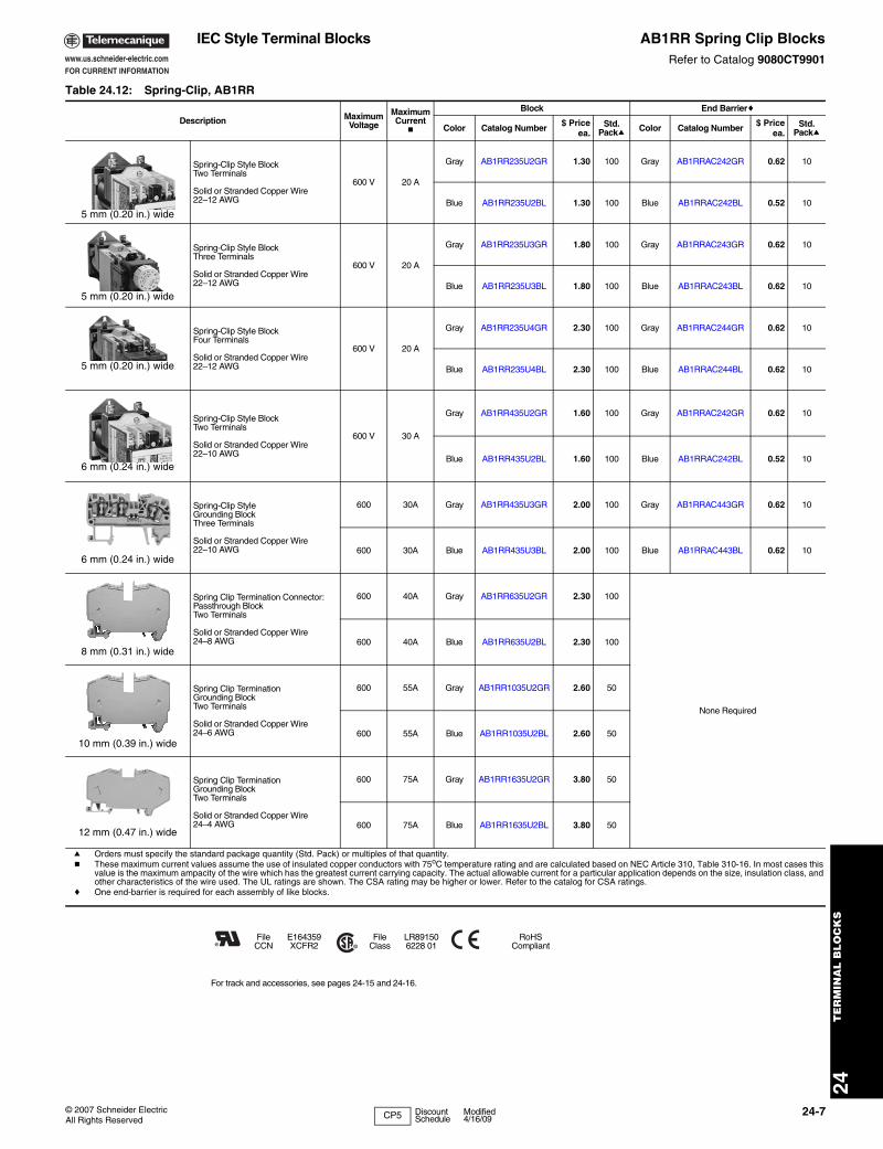
IEC Style Terminal Blocks AB1RR Spring Clip BlocksRefer to Catalog 9080CT9901
For track and accessories, see pages 24-15 and 24-16.
Table 24.12: Spring-Clip, AB1RR
Description MaximumVoltage
Maximum Current
b
Block End Barrierc
Color Catalog Number $ Priceea.
Std. Packa Color Catalog Number $ Price
ea.Std.
Packa
5 mm (0.20 in.) wide
Spring-Clip Style Block Two Terminals
Solid or Stranded Copper Wire22–12 AWG
600 V 20 A
Gray AB1RR235U2GR 1.30 100 Gray AB1RRAC242GR 0.62 10
Blue AB1RR235U2BL 1.30 100 Blue AB1RRAC242BL 0.52 10
5 mm (0.20 in.) wide
Spring-Clip Style BlockThree Terminals
Solid or Stranded Copper Wire22–12 AWG
600 V 20 A
Gray AB1RR235U3GR 1.80 100 Gray AB1RRAC243GR 0.62 10
Blue AB1RR235U3BL 1.80 100 Blue AB1RRAC243BL 0.62 10
5 mm (0.20 in.) wide
Spring-Clip Style BlockFour Terminals
Solid or Stranded Copper Wire22–12 AWG
600 V 20 A
Gray AB1RR235U4GR 2.30 100 Gray AB1RRAC244GR 0.62 10
Blue AB1RR235U4BL 2.30 100 Blue AB1RRAC244BL 0.62 10
6 mm (0.24 in.) wide
Spring-Clip Style BlockTwo Terminals
Solid or Stranded Copper Wire22–10 AWG
600 V 30 A
Gray AB1RR435U2GR 1.60 100 Gray AB1RRAC242GR 0.62 10
Blue AB1RR435U2BL 1.60 100 Blue AB1RRAC242BL 0.52 10
6 mm (0.24 in.) wide
Spring-Clip Style Grounding Block Three Terminals
Solid or Stranded Copper Wire 22–10 AWG
600 30A Gray AB1RR435U3GR 2.00 100 Gray AB1RRAC443GR 0.62 10
600 30A Blue AB1RR435U3BL 2.00 100 Blue AB1RRAC443BL 0.62 10
8 mm (0.31 in.) wide
Spring Clip Termination Connector: Passthrough Block Two Terminals
Solid or Stranded Copper Wire 24–8 AWG
600 40A Gray AB1RR635U2GR 2.30 100
None Required
600 40A Blue AB1RR635U2BL 2.30 100
10 mm (0.39 in.) wide
Spring Clip Termination Grounding BlockTwo Terminals
Solid or Stranded Copper Wire 24–6 AWG
600 55A Gray AB1RR1035U2GR 2.60 50
600 55A Blue AB1RR1035U2BL 2.60 50
12 mm (0.47 in.) wide
Spring Clip Termination Grounding BlockTwo Terminals
Solid or Stranded Copper Wire 24–4 AWG
600 75A Gray AB1RR1635U2GR 3.80 50
600 75A Blue AB1RR1635U2BL 3.80 50
a Orders must specify the standard package quantity (Std. Pack) or multiples of that quantity.b These maximum current values assume the use of insulated copper conductors with 75oC temperature rating and are calculated based on NEC Article 310, Table 310-16. In most cases this
value is the maximum ampacity of the wire which has the greatest current carrying capacity. The actual allowable current for a particular application depends on the size, insulation class, and other characteristics of the wire used. The UL ratings are shown. The CSA rating may be higher or lower. Refer to the catalog for CSA ratings.
c One end-barrier is required for each assembly of like blocks.
FileCCN
E164359XCFR2
FileClass
LR891506228 01
RoHSCompliant
CP5 Discount Schedule
Modified4/16/09
www.us.schneider-electric.comFOR CURRENT INFORMATION
24T
ER
MIN
AL
BL
OC
KS
24-8 © 2007 Schneider ElectricAll Rights Reserved
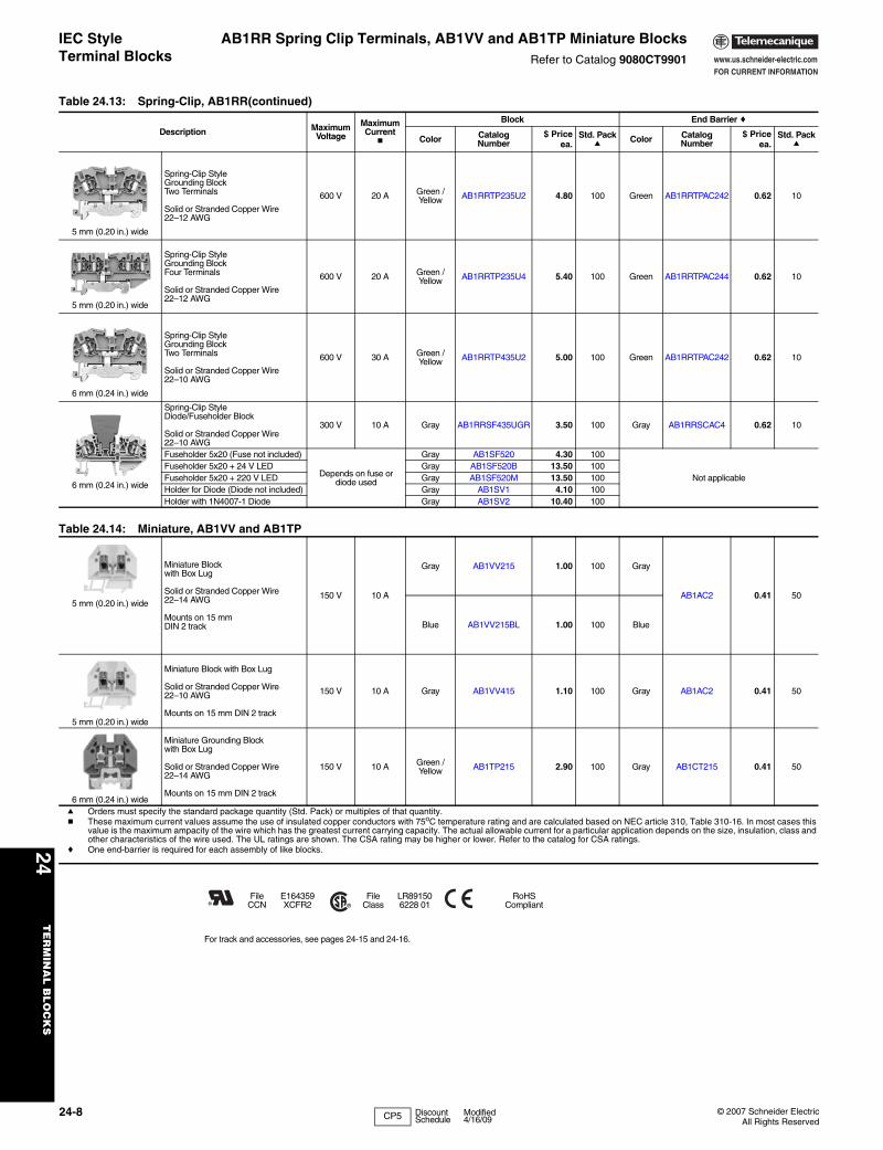
IEC Style Terminal Blocks
AB1RR Spring Clip Terminals, AB1VV and AB1TP Miniature BlocksRefer to Catalog 9080CT9901
For track and accessories, see pages 24-15 and 24-16.
Table 24.13: Spring-Clip, AB1RR(continued)
Description Maximum Voltage
Maximum Current
b
Block End Barrier c
Color Catalog Number
$ Priceea.
Std. Packa
Color Catalog Number
$ Priceea.
Std. Packa
5 mm (0.20 in.) wide
Spring-Clip StyleGrounding BlockTwo Terminals
Solid or Stranded Copper Wire22–12 AWG
600 V 20 A Green / Yellow AB1RRTP235U2 4.80 100 Green AB1RRTPAC242 0.62 10
5 mm (0.20 in.) wide
Spring-Clip StyleGrounding BlockFour Terminals
Solid or Stranded Copper Wire22–12 AWG
600 V 20 A Green /Yellow AB1RRTP235U4 5.40 100 Green AB1RRTPAC244 0.62 10
6 mm (0.24 in.) wide
Spring-Clip StyleGrounding BlockTwo Terminals
Solid or Stranded Copper Wire22–10 AWG
600 V 30 A Green /Yellow AB1RRTP435U2 5.00 100 Green AB1RRTPAC242 0.62 10
6 mm (0.24 in.) wide
Spring-Clip StyleDiode/Fuseholder Block
Solid or Stranded Copper Wire22–10 AWG
300 V 10 A Gray AB1RRSF435UGR 3.50 100 Gray AB1RRSCAC4 0.62 10
Fuseholder 5x20 (Fuse not included)
Depends on fuse or diode used
Gray AB1SF520 4.30 100
Not applicableFuseholder 5x20 + 24 V LED Gray AB1SF520B 13.50 100Fuseholder 5x20 + 220 V LED Gray AB1SF520M 13.50 100Holder for Diode (Diode not included) Gray AB1SV1 4.10 100Holder with 1N4007-1 Diode Gray AB1SV2 10.40 100
Table 24.14: Miniature, AB1VV and AB1TP
5 mm (0.20 in.) wide
Miniature Block with Box Lug
Solid or Stranded Copper Wire 22–14 AWG
Mounts on 15 mm DIN 2 track
150 V 10 A
Gray AB1VV215 1.00 100 Gray
AB1AC2 0.41 50
Blue AB1VV215BL 1.00 100 Blue
5 mm (0.20 in.) wide
Miniature Block with Box Lug
Solid or Stranded Copper Wire 22–10 AWG
Mounts on 15 mm DIN 2 track
150 V 10 A Gray AB1VV415 1.10 100 Gray AB1AC2 0.41 50
6 mm (0.24 in.) wide
Miniature Grounding Block with Box Lug
Solid or Stranded Copper Wire 22–14 AWG
Mounts on 15 mm DIN 2 track
150 V 10 A Green /Yellow AB1TP215 2.90 100 Gray AB1CT215 0.41 50
a Orders must specify the standard package quantity (Std. Pack) or multiples of that quantity.b These maximum current values assume the use of insulated copper conductors with 75oC temperature rating and are calculated based on NEC article 310, Table 310-16. In most cases this
value is the maximum ampacity of the wire which has the greatest current carrying capacity. The actual allowable current for a particular application depends on the size, insulation, class and other characteristics of the wire used. The UL ratings are shown. The CSA rating may be higher or lower. Refer to the catalog for CSA ratings.
c One end-barrier is required for each assembly of like blocks.
FileCCN
E164359XCFR2
FileClass
LR891506228 01
RoHSCompliant
CP5 Discount Schedule
Modified4/16/09

www.us.schneider-electric.comFOR CURRENT INFORMATION
24T
ER
MIN
AL
BLO
CK
S
© 2007 Schneider ElectricAll Rights Reserved
24-9
IEC Style Terminal Blocks
AB1VV Box Lug BlocksRefer to Catalog 9080CT9901
For track and accessories, see pages 24-15 and 24-16.
Table 24.15: Box Lug, AB1VV
Description Maximum Voltage
Maximum Current
b
Block End Barrier c
Color Catalog Number $ Priceea.
Std. Pack a Color Catalog Number $ Price
ea.Std.
Pack a
5 mm (0.20 in.) wide
Box-Lug Style Block
Solid or Stranded Copper Wire 22–12 AWG
600 V 20 A
Gray AB1VV235U 0.93 100 Gray AB1AC24 0.41 50
Blue AB1VV235UBL 0.93 100 Blue AB1AC24BL 0.41 50
Orange AB1VV235UGE 0.93 100 Orange AB1AC24GE 0.41 50
6 mm (0.24 in.) wideBox-Lug Style Block
Solid or Stranded Copper Wire 22–10 AWG
600 V 30 A
Gray AB1VV435U 0.97 100 Gray AB1AC24 0.41 50
Blue3 AB1VV435UBL 0.97 100 Blue AB1AC24BL 0.41 50
Orange AB1VV435UGE 0.97 100 Orange AB1AC24GE 0.41 50
Black AB1VV435UNO 0.97 100 Gray AB1AC24 0.41 50
Red AB1VV435URO 0.97 100 Gray AB1AC24 0.41 50
Green AB1VV435UVE 0.97 100 Gray AB1AC24 0.41 50
White AB1VV435UBLA 0.97 100 Gray AB1AC24 0.41 50
8 mm (0.31 in.) wide
Box-Lug Style Block
Solid or Stranded Copper Wire 22–8 AWG
600 V 50 A
Gray AB1VV635U 1.40 100 Gray AB1AC6 0.41 50
Blue AB1VV635UBL 1.40 100 Blue AB1AC6BL 0.41 50
Orange AB1VV635UGE 1.40 100 Orange AB1AC6GE 0.41 50
Box-Lug Style Block
Solid or Stranded Copper Wire 16–6 AWG
600 V 65 A
Gray AB1VVN1035U 1.80 50 Gray AB1ACN10 0.52 10
Blue AB1VVN1035UBL 1.80 50 Blue AB1ACN10BL 0.52 10
12 mm (0.47 in.) wide
Box-Lug Style Block
Solid or Stranded Copper Wire 12–4 AWG
600 V 85 A
Gray AB1VVN1635U 3.60 50 Gray AB1ACN16 0.62 10
Blue AB1VVN1635UBL 3.60 50 Blue AB1ACN16BL 0.62 10
16 mm (0.63 in.) wide
Box-Lug Style Block
Solid or Stranded Copper Wire 10–2 AWG
600 V 95 A
Gray AB1VVN3535U 5.10 20
Not required for these blocks.
Blue AB1VVN3535UBL 5.10 20
24 mm (0.94 in.) wide
Box-Lug Style Block
Solid or Stranded Copper Wire 6–2/0 AWG
600 V 175 A
Gray AB1VVN7035U 18.60 20
Not required for these blocks.
Blue AB1VVN7035UBL 18.60 20
28 mm (1.10 in.) wide
Box-Lug Style Block
Solid or Stranded Copper Wire 2/0–350 kcmil
600 V 335 A
Gray AB1VVN15035U 43.50 10
Not required for these blocks.
Blue AB1VVN15035UBL 43.50 10
a Orders must specify the standard package quantity (Std. Pack) or multiples of that quantity.b These maximum current values assume the use of insulated copper conductors with 75oC temperature rating and are calculated based on NEC Article 310, Table 310-16. In most cases this
value is the maximum ampacity of the wire which has the greatest current carrying capacity. The actual allowable current for a particular application depends on the size, insulation class, and other characteristics of the wire used. The UL rating are shown. The CSA rating may be higher or lower. Refer to the catalog for CSA ratings.
c One end-barrier is required for each assembly of like blocks.
FileCCN
E164359XCFR2
FileClass
LR891506228 01
RoHSCompliant
CP5 Discount Schedule

www.us.schneider-electric.comFOR CURRENT INFORMATION
24T
ER
MIN
AL
BL
OC
KS
24-10 © 2007 Schneider ElectricAll Rights Reserved
IEC Style Terminal Blocks
AB1TP Grounding and AB1ET Two Tier BlocksRefer to Catalog 9080CT9901
For track and accessories, see pages 24-15 and 24-16
Table 24.16: Grounding, AB1TP
Description Maximum Voltage
Maximum Current b
Block End Barrier c
Color Catalog Number $ Priceea.
Std. Packa
Color Catalog Number
$ Priceea.
Std. Packa
6 mm (0.24 in.) wide
Grounding Block
Solid or Stranded Copper Wire22–12 AWG
600 V 20 A Green/Yellow AB1TP435U 4.10 100 Not required for this block.
8 mm (0.31 in.) wide
Grounding Block
Solid or Stranded Copper Wire22–8 AWG
600 V 30 A Green/Yellow AB1TP635U 4.60 100 Not required for this block.
10 mm (0.39 in.) wide
Grounding Block
Solid or StrandedCopper Wire16–6 AWG
600 V 65 A Green/Yellow AB1TP1035U 5.20 50 Not required for this block.
12 mm (0.47 in.) wide
Grounding Block
Solid or StrandedCopper Wire12–4 AWG
600 V 85 A Green/Yellow AB1TP1635U 6.20 50 Not required for this block.
16 mm (0.63 in.) wide
Grounding Block
Solid or StrandedCopper Wire10–2 AWG
600 V 95 A Green/Yellow AB1TP3535U 8.80 20 Not required for this block.
Table 24.17: Two Tier, AB1ET
DescriptionBlock End Barrier c
Color Catalog Number $ Priceea.
Std. Packa
Color Catalog Number
$ Priceea.
Std. Packa
6 mm (0.24 in.) wideTwo Tier Blocks
Solid or Stranded Copper Wire 22–10 AWG 300 V 20 A b
Standard two tier block Gray AB1ET435U 2.70 100
Gray AB1TE 0.72 50
Standard two tier block + upper-lower link Black AB1ET435U2 4.10 100
Standard two tier block+ grounding Green/Yellow AB1ET435UTP 12.40 100
Standard two tier block + red 24 V LED Red AB1ET435UBRO 11.40 100
Standard two tier block + green 24 V LED Red AB1ET435UBVE 11.40 100
Standard two tier block + head to tail diodes (red) Orange AB1ET435UBGE 11.40 100
Standard two tier block + diode upper-lower Red AB1ET435UHBRO 7.20 100
Standard two tier block+ diode lower-upper Orange AB1ET435UBHGE 7.20 100
Standard two tier block + 2 diodes Red AB1ET435U2DRO 12.80 100
a Orders must specify the standard package quantity (Std. Pack) or multiples of that quantity.b These maximum current values assume the use of insulated copper conductors with 75oC temperature rating and are calculated based on NEC Article 310, Table 310-16. In most cases this
value is the maximum ampacity of the wire which has the greatest current carrying capacity. The actual allowable current for a particular application depends on the size, insulation class, and other characteristics of the wire used. The UL ratings are shown. The CSA rating may be higher or lower. Refer to the catalog for CSA ratings.
c One end-barrier is required for each assembly of like blocks.
FileCCN
E164359XCFR2
FileClass
LR891506228 01
RoHSCompliant
CP5 Discount Schedule

www.us.schneider-electric.comFOR CURRENT INFORMATION
24T
ER
MIN
AL
BLO
CK
S
© 2007 Schneider ElectricAll Rights Reserved
24-11
IEC Style Terminal Blocks
AB1DD, AB1ET Three Tier and AB1ETN Two Tier BlocksRefer to Catalog 9080CT9901
a Orders must specify the standard package quantity (Std. Pack) or multiples of that quantity.b These maximum current values assume the use of insulated copper conductors with 75oC temperature rating and are calculated based on NEC Article
310, Table 310-16. In most cases this value is the maximum ampacity of the wire which has the greatest current carrying capacity. The actual allowable current for a particular application depends on the size, insulation class, and other characteristics of the wire used. The UL ratings are shown. The CSA rating may be higher or lower. Refer to the catalog for CSA ratings.
c One end-barrier is required for each assembly of like blocks.
For track and accessories, see pages 24-15 and 24-16.
Table 24.18: Three Tier, AB1DD and AB1ET
Description Maximum Voltage
Maximum Currentb
Block End Barrier c
Color Catalog Number $ Price ea.
Std. Packa
Color Catalog Number
$ Price ea.
Std. Packa
6 mm (0.24 in.) wide
Three Tier Block
Solid or Stranded Copper Wire22–12 AWG
300 V 25 A
Gray
AB1DDP235U 3.60 100
Not required for these blocks.
Three Tier Blockwith 24 V LED (+)
Solid or Stranded Copper Wire 22–12 AWG
AB1DDP235ULP 6.70 100
Three Tier Block with 24 V LED (-)
Solid or Stranded Copper Wire 22–12 AWG
AB1DDP235ULM 6.70 100
6 mm (0.24 in.) wide
Three Tier Block with ground
Solid or Stranded Copper Wire 22–12 AWG
Gray withGreen/Yellow
AB1DDP235T 5.70 100
Three Tier Block with 24 V LED (+) and ground
Solid or Stranded Copper Wire 22–12 AWG
AB1DDP235TLP 8.80 100
Three Tier Block with 24 V LED (-) and ground
Solid or Stranded Copper Wire22–12 AWG
AB1DDP235TLM 8.80 100
6 mm (0.24 in.) wide
Three Tier Block
Solid or Stranded Copper Wire22–12 AWG
Gray AB1ET3235U 5.70 100
Three Tier Block with 24 V LED (+) and ground
Solid or Stranded Copper Wire 22–12 AWG
Gray withGreen/Yellow
AB1ET3235UTLP 18.50 100
Three Tier Block with 24 V LED (-) and ground
Solid or Stranded Copper Wire 22–12 AWG
AB1ET3235UTLM 18.50 100
Three Tier Block with ground
Solid or Stranded Copper Wire 22–12 AWG
AB1ET3235UT 8.40 100
Table 24.19: Two Tier, AB1ETN
Description Maximum Voltage
Maximum Current b
Block End Barrier c
Color Catalog Number
$ Price ea.
Std. Packa
Color Catalog Number
$ Price ea.
Std. Packa
6 mm (0.24 in.) wide
Two Tier Block (one terminal in and two out)
Solid or Stranded Copper Wire 22–10 AWG
300 V 30 A
Gray AB1ETN335U 2.40 100 Gray AB1TEN3 0.72 10
Two Tier Block (two terminals in and two out)
Solid or Stranded Copper Wire 22–10 AWG
Gray AB1ETN435U 3.40 100 Gray AB1TEN4 0.83 10
Grounding Block (two terminals in and two out)
Solid or Stranded Copper Wire 22–10 AWG
Green/Yellow AB1ETNTP435U 8.10 100 Not required for this block.
FileCCN
E164359XCFR2
FileClass
LR891506228 01
RoHSCompliant
CP5 Discount Schedule
www.us.schneider-electric.comFOR CURRENT INFORMATION
24T
ER
MIN
AL
BL
OC
KS
24-12 © 2007 Schneider ElectricAll Rights Reserved
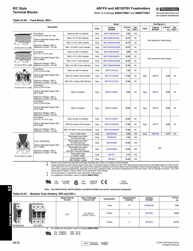
IEC Style Terminal Blocks
AB1FU and AB1SF/SV FuseholdersRefer to Catalogs 9080CT9901 and 9080CT0001
a Orders must specify the standard package quantity (Std. Pack) or multiples of that quantity.b These maximum current values assume the use of insulated copper conductors with 75oC temperature rating and are calculated based on NEC Article
310, Table 310-16. In most cases this value is the maximum ampacity of the wire which has the greatest current carrying capacity. The actual allowable current for a particular application depends on the size, insulation class, and other characteristics of the wire used. The UL ratings are shown. The CSA rating may be higher or lower. Refer to the catalog for CSA ratings.
c One end-barrier is required for each assembly of like blocks.d For additional information, refer to Catalog 9080CT9901
Note: The AB1FU10135, AB1FU10235U, and AB1FU10335U are not UL component recognized.
e For additional information, refer to Catalog 9080CT0001
Table 24.20: Fuse Block, AB1d
DescriptionBlock End Barrier c
Color Catalog Number
$ Priceea.
Std. Pack a Color Catalog
Number$ Price
ea.Std.
Pack a
8 mm (0.31 in.) wide
Fuse Block For 5x20 or 5x25 mm fuse
Solid or Stranded Copper Wire 22–10 AWG
Maximum Voltage—600 VMaximum Current—15 A b
Open up with no indicator Gray AB1FUSE435U5X 5.20 100
Not required for these blocks.With 5–12 V LED indicator Gray AB1FUSE435U5XJ 10.70 50
With 12–24 V LED indicator Gray AB1FUSE435U5XB 10.70 50
With 110–250 V neon indicator Gray AB1FUSE435U5XM 10.70 50
10 mm (0.39 in.) wide
Fuse Block For 1/4 x 1-1/4 in. fuse
Solid or Stranded Copper Wire 22–10 AWG
Maximum Voltage—600 VMaximum Current—15 A b
Open up with no indicator Gray AB1FUSE435U6X 9.60 100
Not required for these blocks.With 5–12 V LED indicator Gray AB1FUSE435U6XJ 12.40 50
With 12–24 V LED indicator Gray AB1FUSE435U6XB 12.40 50
With 110–250 V neon indicator Gray AB1FUSE435U6XM 12.40 50
12 mm (0.47 in.) wide
Fuse Block For 5 x 20 mm fuse
Solid or Stranded Copper Wire 22–6 AWG
Maximum Voltage—600 VMaximum Current—15 A b
Open up with no indicator Gray AB1FU10135U 7.20 50
Gray AB1TF 0.93 50With 28 V yellow LED indicator Gray AB1FU10135UB 17.60 50
With 250 V yellow LED indicator Gray AB1FU10135UU 17.60 50
Fuse Block For 5 x 25 mm fuse
Solid or Stranded Copper Wire 22–6 AWG
Maximum Voltage—600 V Maximum Current—15 A b
With no indicator Gray AB1FU10235U 9.30 50 Gray AB1TF 0.93 50
Fuse Block For 5 x 30 mm fuse
Solid or Stranded Copper Wire 22–6 AWG
Maximum Voltage—600 V Maximum Current—15 A b
With no indicator Gray AB1FU10335U 10.40 50 Gray AB1TF 0.93 50
Fuse Block For 1/4 x 1-1/4 in. fuse
Solid or Stranded Copper Wire 22–6 AWG
Maximum Voltage—600 V Maximum Current—15 A b
Open up with no indicator Gray AB1FU10435U 10.40 50
Gray AB1TF 0.93 50With 28 V yellow LED indicator Gray AB1FU10435UB 17.60 50
With 110–500 V red neon indicator Gray AB1FU10435UFS 17.60 50
6 mm (0.24 in.) wide
Fuse / Diode Block
Solid or Stranded Copper Wire 22–10 AWG
Maximum Voltage—300 V Maximum Current—10 A b
Fuse / Diode block Gray AB1SF435U 2.60 100 Gray AB1PS4 0.57 50Removable fuse holder
for 5x20 mm fuse Gray AB1SF520 4.30 100
N/A
Removable fuse holder for 5x20 mm fuse
with 24 V red LED indicatorGray AB1SF520B 13.50 100
Removable fuse holder for 5x20 mm fuse
with 220 V red LED indicatorGray AB1SF520M 13.50 100
Removable diode or resistor holder Gray AB1SV1 4.10 100
Removable holder With 1N4007.1 diode Gray AB1SV2 10.40 100
FileCCN
E164359XCFR2
FileClass
LR891506228 01
RoHSCompliant
Table 24.21: Modular Fuse Holders, DF6 and GK1e
Rated Thermal Current
Size of Cartridge Fuse or Link Composition Standard Pack
QuantityCatalog Number
$ Priceea.
DF6AB10U GK1DFU
32 A 10 x 38 mm(0.39 X 1.50 in.)
1 Pole 12 DF6AB10U 7.20
2 Poles 6 GK1DDU 14.50
3 Poles 4 GK1DFU 21.70
FileFile
E308204E308204
CNNCNN
1ZLT21ZLT8
CP5 Discount Schedule
Modified4/16/09

www.us.schneider-electric.comFOR CURRENT INFORMATION
24T
ER
MIN
AL
BLO
CK
S
© 2007 Schneider ElectricAll Rights Reserved
24-13
IEC Style Terminal Blocks
AB1 Other BlocksRefer to Catalog 9080CT9901
a Orders must specify the standard package quantity (Std. Pack) or multiples of that quantity.b These maximum current values assume the use of insulated copper conductors with 75oC temperature rating and are calculated based on NEC Article
310, Table 310-16. In most cases this value is the maximum ampacity of the wire which has the greatest current carrying capacity. The actual allowable current for a particular application depends on the size, insulation class, and other characteristics of the wire used. The UL ratings are shown. The CSA rating may be higher or lower. Refer to the catalog for CSA ratings.
c One end-barrier is required for each assembly of like blocks.
For track and accessories, see pages 24-15 and 24-16.
Table 24.22: Other Blocks, AB1
Description
Block End Barrierc
Color Catalog Number $ Priceea.
Std. Packa
Color Catalog Number
$ Priceea.
Std. Packa
12 mm (0.47 in.) wide
Block for Diodes (Diodes not included)
Solid or Stranded Copper Wire22–10 AWG
Gray AB1D11435U 8.30 50 Not required for this block.
6 mm (0.24 in.) wide
Circuit Isolation Block
Solid or Stranded Copper Wire 22–10 AWG
Maximum Voltage—600 V Maximum Current—20 Ab
With no test sockets Gray AB1SC435U 4.70 50
Gray AB1PS4 0.57 50
With two test sockets Gray AB1SC435U2PT 4.70 50
6 mm (0.24 in.) wide
Box Lug / Slip-on Block
Solid or Stranded Copper Wire 22–14 AWG
Maximum Voltage—300 V Maximum Current—10 Ab
Box lug on one side. Slip-on access from top
and sideGray AB1FV135U 2.00 100 Gray AB1TC01 0.93 50
Box lug on one side. Slip-on access from top Gray AB1FC335U 2.60 100 Gray AB1TC3 0.93 50
Slip-on connectors on both sides Gray AB1FF235U 1.40 100 Not required for this block.
Table 24.23: Lug/Lug and Lug/Clamp, AB1
Description
Block Partition
Color Catalog Number
$ Priceea.
Std. Packa
Color Catalog Number
$ Priceea.
Std. Packa
32 mm (1.26 in.) wide
Lug/Lug Block
Solid or Stranded Copper Wire 6–3/0 AWG
M10 bolt Maximum Voltage—600 V
Maximum Current—200 AbGray AB1BB9535 14.20 10 Gray AB1CT1 1.60 50
42 mm (1.65 in.) wide
Lug/Lug Block
Solid or Stranded Copper Wire 1/0–400 kcmil
M12 bolt Maximum Voltage—600 V
Maximum Current—325 AbGray AB1BB18535 18.20 10 Gray AB1CT2 1.80 50
42 mm (1.65 in.) wide
Lug/Lug Block
Solid or Stranded Copper Wire 1/0–500 kcmil
M12 bolt Maximum Voltage—600 V
Maximum Current—375 AbGray AB1BB24035 30.00 10 Gray AB1CT2 1.80 50
32 mm (1.26 in.) wide
Lug/Clamp Block
Solid or Stranded Copper Wire 6–3/0 AWG
M10 bolt Maximum Voltage—600 V
Maximum Current—200 AbGray AB1BC9535 20.70 10 Gray AB1CT1 1.60 50
42 mm (1.65 in.) wide
Lug/Clamp Block
Solid or Stranded Copper Wire 1/0–300 kcmil
M12 bolt Maximum Voltage—600 V
Maximum Current—325 AbGray AB1BC15035 41.40 10 Gray AB1CT2 1.80 50
42 mm (1.65 in.) wide
Lug/Clamp Block
Solid or Stranded Copper Wire 1/0–500 kcmil
M12 boltMaximum Voltage—600 V
Maximum Current—375 AbGray AB1BC24035 57.00 10 Gray AB1CT2 1.80 50
FileCCN
E164359XCFR2
FileClass
LR891506228 01
RoHSCompliant
CP5 Discount Schedule

www.us.schneider-electric.comFOR CURRENT INFORMATION
24T
ER
MIN
AL
BL
OC
KS
24-14 © 2007 Schneider ElectricAll Rights Reserved
IEC Terminal Blocks AB1AA Insulation Displacement BlocksRefer to Catalog 9080CT9901
Insulation Displacement Style Terminal Blocks and Accessories
a Orders must specify the standard package quantity (Std. Pack) or multiples of that quantity.b These maximum current values assume the use of insulated copper conductors with 75oC temperature rating and are calculated based on NEC Article
310, Table 310-16. In most cases this value is the maximum ampacity of the wire which has the greatest current carrying capacity. The actual allowable current for a particular application depends on the size, insulation class, and other characteristics of the wire used.
c One end-barrier is required for each assembly of like blocks.
For track and accessories, see pages 24-15 and 24-16.
5 mm (0.20 in.) wideAB1AA135U4••
• Insert wires without stripping• Available for wire sizes 30-14 AWG• DIN 3 rail mounting• Finger safe connections
The complete line is available in the IEC Sectional Terminal Block Catalog #9080CT9901.
Table 24.24: Insulation Displacement, AB1AA
Description Maximum Voltage
Maximum Currentb Wire Size
Block End Barrierc
No. of Poles Color Catalog Number $ Price
ea.Std.
Packa Color Catalog Number $ Priceea.
Std. Packa
Insulation Displacement Connector: Passthrough Block Solid or Stranded Copper Wire
AB1AA135U2••
UL 600 V 13 A 30–18 AWG 2Gray AB1AA135U2GR 1.20 100 Gray AB1AAAC122GR .41 10Blue AB1AA135U2BL 1.20 100 Blue AB1AAAC122BL .41 10
UL 600 V 13 A 18–14 AWG 2Gray AB1AA235U2GR 1.30 100 Gray AB1AAAC122GR .41 10Blue AB1AA235U2BL 1.30 100 Blue AB1AAAC122BL .41 10
UL 600 V 10 A 30–18 AWG 3Gray AB1AA135U3GR 1.90 100 Gray AB1AAAC123GR .52 10Blue AB1AA135U3BL 1.90 100 Blue AB1AAAC123BL .52 10
UL 600 V 10 A 18–14 AWG 3Gray AB1AA235U3GR 2.00 50 Gray AB1AAAC123GR .52 10Blue AB1AA235U3BL 2.00 50 Blue AB1AAAC123BL .52 10
UL 600 V 10 A 30–18 AWG 4Gray AB1AA135U4GR 3.90 50 Gray AB1AAAC124GR .62 10Blue AB1AA135U4BL 3.90 50 Blue AB1AAAC124BL .62 10
UL 600 V 10 A 18–14 AWG 4Gray AB1AA235U4GR 4.00 100 Gray AB1AAAC124GR .62 10
Blue AB1AA235U4BL 4.00 100 Blue AB1AAAC124BL .62 10
Insulation DisplacementConnector: Grounding Block
AB1AATP135U3
UL 600 V 13 A 30–18 AWG 2 Green/Yellow AB1AATP135U2 3.90 100 Green/
Yellow AB1AAAC122VE .411010
UL 600 V 13 A 18–14 AWG 2 Green/Yellow AB1AATP235U2 4.10 100 Green/
Yellow AB1AAAC122VE .411010
UL 600 V 10 A 30–18 AWG 3 Green/Yellow AB1AATP135U3 3.90 100 Green/
Yellow AB1AAAC123VE .52 10
UL 600 V 10 A 18–14 AWG 3 Green/Yellow AB1AATP235U3 5.40 100 Green/
Yellow AB1AAAC123VE .52 10
UL 600 V 10 A 30–18 AWG 4 Green/Yellow AB1AATP135U4 9.10 50 Green/
Yellow AB1AAAC124VE .62 10
UL 600 V 10 A 18–14 AWG 4 Green/Yellow AB1AATP235U4 9.30 50 Green/
Yellow AB1AAAC124VE .62 10
Two Tier Block UL 600 V 10 A 30–18 AWG 2 Gray AB1AAET135UGR 3.20 50 Gray AB1AAAC124GR .62 10
AB1AAET235••
UL 600 V 10 A 18–14 AWG
2 Gray AB1AAET235UGR 3.40 50 Gray AB1AAAC124GR .62 10
2 Red AB1AAET235URO 3.40 50 Red AB1AAAC124GR .62 10
2 Orange AB1AAET235UGE 3.40 50 Orange AB1AAAC124GR .62 10
4 Red AB1AAET235UBRO 10.40 50 Red AB1AAAC124GR .62 10
4 Orange AB1AAET235UBGE 10.40 50 Orange AB1AAAC124GR .62 10
Fuse Block
AB1AASF135U••
UL 600 V 6.3 A 30–18 AWG 2 Gray AB1AASF135UGR 3.30 50 Gray AB1AAAC123GR .52 10
UL 600 V 6.3 A 18–14 AWG 2 Gray AB1AASF235UGR 3.50 50 Gray AB1AAAC123GR .52 10
Disconnect Block UL 600 V 10 A 18–14 AWG 2Gray AB1AASC235UGR 4.00 50 Gray AB1AAAC123GR .52 10Blue AB1AASC235UBL 4.00 50 Blue AB1AAAC123BL .52 10
5 mm (0.20 in.) wide
5 mm (0.20 in.) wide
6 mm (0.24 in.) wide
6 mm (0.24 in.) wide
FileCCN
E164359XCFR2
FileClass
LR891506228 01
RoHSCompliant
CP5 Discount Schedule
Modified4/16/09

www.us.schneider-electric.comFOR CURRENT INFORMATION
24T
ER
MIN
AL
BLO
CK
S
© 2007 Schneider ElectricAll Rights Reserved
24-15
IEC Style Terminal Blocks AB1 MarkersRefer to Catalog 9080CT9901
a Orders must specify the standard package quantity (Std. Pack) or multiples of that quantity.
RoHS Compliant
Table 24.25: Markers, AB1
Marking Catalog Number
$ Priceea.
Std. Pack a
Black number on white background
5 mm (0.20 in.) wide
Blank AB1BV5
0.52 25
1–10 AB1B51011–20 AB1B52021–30 AB1B53031–40 AB1B54041–50 AB1B55051–60 AB1B56061–70 AB1B57071–80 AB1B58081–90 AB1B59091–100 AB1B5100
Black number on white background
6 mm (0.24 in.) wide
Blank AB1BV6
0.52 25
1–10 AB1B61011–20 AB1B62021–30 AB1B63031–40 AB1B64041–50 AB1B65051–60 AB1B66061–70 AB1B67071–80 AB1B68081–90 AB1B69091–100 AB1B6100
L1 AB1B6L1L2 AB1B6L2L3 AB1B6L3
+ (Red) AB1BV6RPx—(Blue) AB1BV6BM
Black number on white background
8 mm (0.31 in.) wide
Blank AB1BV8
0.52 25
1–10 AB1B81011–20 AB1B82021–30 AB1B83031–40 AB1B84041–50 AB1B85051–60 AB1B86061–70 AB1B87071–80 AB1B88081–90 AB1B89091–100 AB1B8100
Black number or symbol on white background
Blank AB1RV
0.52 25
1 AB1R12 AB1R23 AB1R34 AB1R45 AB1R56 AB1R67 AB1R78 AB1R89 AB1R90 AB1R0
0–9 AB1R11+ AB1R12– AB1R13
12345678910AB1B510
12345678910
AB1B610
12345678910
AB1B810
2 2 2 2 2 2 2 2 2 2
AB1R2
Marking Catalog Number
$ Priceea.
Std. Pack a
Black capital letters on white background
A AB1GA
0.52 25
B AB1GBC AB1GCD AB1GDE AB1GEF AB1GFG AB1GGH AB1GHI AB1GIJ AB1GJK AB1GKL AB1GLM AB1GMN AB1GNO AB1GOP AB1GPQ AB1GQR AB1GRS AB1GST AB1GTU AB1GUV AB1GVW AB1GWX AB1GXY AB1GYZ AB1GZ
AB1SR6 0.52 200
AB1SA1 0.12 500
AB1SA2 0.26 500
AB1SA3 0.52 500
AB1RT 0.52 500
AR1SB2 1.00 100
AR1SB3 0.90 50
A A A A A A A A A A
AB1GA
CP5 Discount Schedule
Modified4/16/09

www.us.schneider-electric.comFOR CURRENT INFORMATION
24T
ER
MIN
AL
BL
OC
KS
24-16 © 2007 Schneider ElectricAll Rights Reserved
IEC Style Terminal Blocks
Mounting Track and End ClampsRefer to Catalog 9080CT9901
a Orders must specify the standard package quantity (Std. Pack) or multiples of that quantity.
b Not RoHS compliant
c Not RoHS Compliant
RoHS Compliant
Table 24.26: DIN 3 Track – Various Lengths
Description Lengthm (in.)
Class 9080Type
$ Priceea.
Std.aPack
Symmetrical rail 35 x 7.5 mm(1.38 in. x 0.295 in.) in compliance with EN 50022 standard (DIN 46277-3).
Galvanized steel,
no mounting holes
0.08 (3) MH203 2.10
10
0.10 (4) MH204 2.400.13 (5) MH205 2.700.15 (6) MH206 3.100.18 (7) MH207 3.400.20 (8) MH208 3.700.23 (9) MH209 4.100.25 (10) MH210 4.500.28 (11) MH211 4.800.30 (12) MH212 5.200.33 (13) MH213 5.500.36 (14) MH214 5.800.38 (15) MH215 6.200.41 (16) MH216 6.500.42 (17) MH217 6.800.46 (18) MH218 7.20
0.50 (19.68) MH220 7.701 (39.37) MH239 13.102 (78.74) MH279 19.70
Galvanized steel,
prepunched
0.08 (3) MH303 2.300.10 (4) MH304 2.60
0.13 (5 in. MH305 3.100.15 (6) MH306 3.400.18 (7) MH307 3.800.20 (8) MH308 4.100.23 (9) MH309 4.600.25 (10) MH310 4.900.28 (11) MH311 5.400.30 (12) MH312 5.700.33 (13) MH313 6.100.36 (14) MH314 6.400.38 (15) MH315 6.800.41 (16) MH316 7.200.42 (17) MH317 7.700.46 (18) MH318 8.00
0.50 (19.68) MH320 8.701 (39.37) MH339 15.302 (78.74) MH379 21.80
High rise track Aluminum 1 (39.37) MH439b 18.60 2
Dimensions
Angle bracket kit Catalog Number
$Price
ea.
Std.aPack
For mounting 9080GH or MH track to a panel at 45o angle. Includes 2 brackets and hardware for mounting the track to the brackets.
9080MH82c 4.80 1
End Clamps
Plastic end clamp for 35 mm DIN 3 track, 8 mm (0.31 in.) wide AB1AB8P35 1.00 100
Metal end clamp for 35 mm DIN 3 track, 8 mm (0.31 in.) wide AB1AB8M35 1.60 100
Polycarbonate end clamp for 35 mm DIN 3 track, 8 mm (0.31 in.) wide 9080MHA10c 1.60 50
.256
A
.308.04
1
.9825
1.3835
9080MH3**
.7118
.9825
1.8046
1.1730
9080MHA10
Table 24.27: Mounting Track 1 or 2 meter length
Description Lengthm (in.) Catalog Number $ Price
ea.Std. aPack
DIN 3
15 mm depth, 1 mm steel, zinc chromated
2 (78.74) AM1ED200 9.80 10
15 mm depth, 1.5 mm steel, zinc chromated
2 (78.74) AM1DE200 14.50 10
7.5 mm depth, 1 mm steel, zinc chromated
EN 50022 & NF C63-015
2 (78.74) AM1DP200 5.20 10
DIN 1
Asymmetrical 32 mm trackEN 50035 & NF C63-018
2 (78.74) DZ5MB201 15.50 10
15 mm steel, zinc chromated
DIN 2
Symmetrical 15 mm trackEN 50045
1 (39.37) AB1PC15 5.00 10
Dimensions
End Clamps Catalog Number
$ Priceea.
Std.aPack
Plastic end clamp for 32 mm DIN 1 track, 7.5 mm (0.30 in.) wide AB1AB7P32 1.70 100
Metal end clamp for 32 mm DIN 1 track, 7.5 mm (0.30 in.) wide AB1AB10M32 1.70 100
Plastic end clamp for 15 mm DIN 2 track, 7.5 mm (0.30 in.) wide AB1AB715 1.00 100
AM1DE200
.062
1.3835
78.742000
.5915
1.0627
AM1ED200
1.3835
1.0627
.28778.74
2000.5915
.041
.4912
.9825
.9825
.9825
.308
AM1DP200
1.0627
1.3835
.28778.74
2000
.4912
.9825
.9825
.9825
.308
.041
.041
AB1PC15
39.371000
.205
.349
.5915
DZ5MB201
.246
.6517
.062 .59
15
1.2632
78.742000
CP5 Discount Schedule

www.us.schneider-electric.comFOR CURRENT INFORMATION
24T
ER
MIN
AL
BLO
CK
S
© 2007 Schneider ElectricAll Rights Reserved
24-17
Thermal-Magnetic Circuit Protectors
Type GCBClass 9080 / Refer to Catalog 9080CT9901
a These maximum current values assume the use of insulated copper conductors with 75oC temperature rating, and are calculated based on NEC Article 310, Table 310-16. In most cases this value is the maximum ampacity of that wire or combination of wires (as listed in the above table) which has the greatest current carrying capacity. The actual allowable current for a particular application depends on the number, size, insulation class, and other characteristics of the wires used.
b Replacement adapter is 9080GH64, $1.10 each, standard pack of 10.c Discount schedule CP5.
Thermal-Magnetic Circuit Protectors
Type GB2www.us.schneider-electric.com
GCB100
Table 24.28: 9080GCB Thermal-Magnetic Circuit Protectorsc
Maximum Currentb (A) Internal Resistance¾ Maximum Voltage Catalog Numbera $ Price
0.1 133
250 Vac65 Vdc
GCB01
43.70
0.5 6.6 GCB050.8 2.55 GCB081.0 1.97 GCB101.2 1.22 GCB121.5 0.86 GCB152.0 0.49 GCB20
48.00
2.5 0.31 GCB253.0 0.20 GCB304.0 0.10 GCB405.0 0.08 GCB507.0 0.03 GCB70
10.0 <0.02 125 Vac65 Vdc
GCB10015.0 <0.02 GCB150
SelectionTo properly select a Class 9080 Type GCB circuit protector, follow these steps:
1. Determine the inrush correction factor from Table 24.29.2. Determine the temperature correction factor from Table 24.30.3. Determine the sealed current of the load that is being protected.4. Multiply the sealed current by the two correction factors and choose
the closest circuit protector.
Note: Choosing a circuit protector with a value lower than the calculated value might cause nuisance tripping, while choosing the larger might provide a protector that will not properly protect the load.
Table 24.29: Table A—Inrush Ratio Correction TableNote: For resistive loads, use inrush correction factor of 1.0.
Inrush Ratio 1:1 to 1:4 1:5 1:6 1:7 1:8
Factor 1.3 1.4 1.5 1.6 1.7
Table 24.30: Table B—Ambient Temperature Correction Table
AmbientTemperature
70oF 100oF 120oF 140oF 160oF 180oF 200oF
(21.1oC) (37.8oC) (48.9oC) (60oC) (71.1oC) (82.2oC) (93.3oC)
Factor 1.0 1.1 1.2 1.3 1.4 1.5 1.6
FileCCN
E152841QVNU2
Example: Solenoid with sealed current of 0.75 A, an inrush ratio of 1:6, and in an ambient temperature of 85oF: 0.75 x 1.5 x 1.05 = 1.18 Choose the 1.2 A protector
Tripping Time: Tripping time of the circuit protector is determined from Table 24.31. Divide the circuit protector value by the temperature correction factor from Table 24.30 to determine actual rated current referenced in Table 24.31.
Table 24.31: Table C—Tripping Times in Seconds at 70oF (21.1oC)Percent ratedcurrent 100% 200% 300% 400% 500% 600% 1000% 2000% and
greaterFile UL1077
Tripping Time (s) no trip 10–40 38 1.5–9 0.8–6 0.003–4 0.003–2 Max. 0.02
File LR25490Note: When several protectors are channel mounted adjacent to each other, the “no trip” current will be
80% of rated current at 70oF.
CP5 Discount Schedule
Table 24.32: GB2 Thermal-Magnetic Circuit Protectorsd
Description Maximum Voltage
Thermal Rating
Catalog Number $ Price ea.e Description Maximum
VoltageThermal Rating
Catalog Number $ Price ea.e
One pole Thermal Magnetic Circuit Protector
300 Vac
0.5 A GB2CB05
43.60
Two pole Thermal Magnetic Circuit Protector
300 Vac
0.5 A GB2CD05
52.00
1 A GB2CB06 1 A GB2CD06
2 A GB2CB07 2 A GB2CD07
3 A GB2CB08 3 A GB2CD08
4 A GB2CB09 4 A GB2CD09
5 A GB2CB10 5 A GB2CD10
6 A GB2CB12 6 A GB2CD12
8 A GB2CB14 8 A GB2CD14
10 A GB2CB16 10 A GB2CD16
12 A GB2CB20 12 A GB2CD20
d Discount schedule I.e Must order in multiples of 6
Note: For markers, use AB1( )R and AB1( )G markers from page 24-15
FileCCN
E164873QVNU2 File UL1077 File
ClassLR25490321501
IEC 157-1VDE 0660
GB2-CB06
GB2-CD
I Discount Schedule

www.us.schneider-electric.comFOR CURRENT INFORMATION
24T
ER
MIN
AL
BL
OC
KS
24-18 © 2007 Schneider ElectricAll Rights Reserved
Power Distribution Blocks Type LBClass 9080 / Refer to Catalog 9080CT9603
f These covers must be ordered in multiples of 5. Each cover comes with two self-tapping screws.g Will not work on a 9080LBA362106 block.
Application DataUL component recognized (File E60616 CCN XCFR2). CSA certified (File LR70361). Voltage Rating—Class B & C—600 VBlocks are rated based on NEC Table 310-16 using 75oC wire.Aluminum blocks are tin plated high conductive aluminum.Copper blocks are tin plated high conductive copper.Housing material:• Miniature Blocks are made from high impact thermoplastic rated at 125oC. max. & -40oC. min.• Full Size Blocks are made from general purpose phenolic rated at 150oC. max. & -40oC. min.All blocks have a flammability rating of UL 94V-0.Most blocks have a short circuit current rating for UL508A up to 200 kA for branch circuit applications. For the actual ratings, see catalog 9080CT9603.RoHS Compliant
LBA365212
LBA161104
LBC165212
Table 24.33: Standard Power Distribution BlocksLug Wire Rangea Aluminumb
Dim.TypeMain Branch
One Pole Two Pole Three Pole
Type d $ Price Type d $ Price Type d $ Price
(1) #14–2/0 (1) #14–2/0 LBA162101 6.90 LBA262101 14.70 LBA362101 17.10 2
(1) #6–350 kcmil (1) #6–350 kcmil LBA163101 35.60 LBA263101 54.00 LBA363101 71.00 3
(1) #4–600 kcmil (1) #4–600 kcmil LBA164101 63.00 N/A — LBA364101 122.00 4
(2) #4–350 kcmil (2) #4–350 kcmil LBA165202 65.00 LBA265202 98.00 LBA365202 126.00 5
(2) #4–500 kcmil (2) #4–500 kcmil LBA1652021 90.00 LBA2652021 137.00 LBA3652021 162.00 5
(1) #14–2/0 (4) #14–4 LBA162104 20.30 LBA262104 30.50 LBA362104 45.60 2
(1) #14–2/0 (6) #14–4 N/A — N/A — LBA362106 87.00 —e
(1) #6–400 kcmil (4) #14–2 LBA163104 37.20 LBA263104 56.00 LBA363104 75.00 3
(1) #6–400 kcmil (6) #14–2 LBA163106 39.30 LBA263106 59.00 LBA363106 81.00 3
(1) #6–400 kcmil (8) #14–2 LBA164108 51.00 LBA264108 77.00 LBA364108 107.00 4
(1) #4–500 kcmil (6) #14–2/0 LBA165106 84.00 LBA265106 126.00 LBA365106 155.00 5
(1) #4–500 kcmil (12) #14–2 LBA165112 89.00 LBA265112 134.00 LBA365112 174.00 5
(2) #14–2/0 (6) #14–4 LBA163206 39.80 LBA263206 60.00 LBA363206 81.00 3
(2) #4–500 kcmil (8) #14–2/0 LBA165208 84.00 LBA265208 126.00 LBA365208 167.00 5
(2) #4–500 kcmil (12) #14–4 LBA165212 90.00 LBA265212 137.00 LBA365212 174.00 5
Table 24.34: Miniature Power Distribution BlocksLug Wire Rangea Aluminumb
Dim.TypeMain Branch
One Pole Two Pole Three Pole
Type d $ Price Type d $ Price Type d $ Price
(1) #14–2 (1) #14–2 LBA161101 8.90 N/A — LBA361101 15.60 1
(1) #14–2 (4) #18–10 LBA161104 17.60 LBA261104 20.40 LBA361104 38.70 1
Table 24.35: Copper Power Distribution BlocksLug Wire Rangea Copperc
Dim.TypeMain Branch
One Pole Two Pole Three Pole
Type d $ Price Type d $ Price Type d $ Price
(1) #18–1/0 (1) #18–1/0 LBC162101 66.00 N/A — LBC362101 134.00 2
(1) #6–250 kcmil (1) #6–250 kcmil LBC163101 83.00 N/A — LBC363101 155.00 3
(1) #14–2/0 (4) #14–4 LBC162104 66.00 LBC262104 98.00 LBC362104 165.00 2
(1) #4–500 kcmil (6) #14–2 LBC163106 102.00 LBC263106 152.00 LBC363106 236.00 3
(2) #14–2/0 (6) #14–4 LBC163206 89.00 LBC263206 134.00 LBC363206 179.00 3
(2) #4–500 kcmil (8) #14–2/0 LBC165208 198.00 N/A — LBC365208 395.00 5
(2) #4–500 kcmil (12) #14–2 LBC165212 189.00 N/A — LBC365212 378.00 5
a Lugs suitable for use with 75oC conductors. (#) indicates number of conductors.b Aluminum blocks will accept either Al or Cu conductors.c Cu blocks will accept copper conductors only.
d CE Marked.e Refer to catalog for dimensions.
Table 24.36: Dimensions (inches)Type A1 A2 A3 B C D E F G H J
1 .76 1.40 2.03 2.29 1.62 .38 .64 .19 1.93 .32 .2012 1.13 1.94 2.75 2.88 1.78 .56 .81 .31 2.25 .24 .2053 1.94 3.47 5.00 4.00 2.61 .97 1.53 .31 3.38 .40 .2034 2.28 4.16 6.04 4.75 2.92 1.14 1.88 .31 4.13 .51 .205 3.17 5.88 8.54 5.50 3.12 1.58 2.69 .38 4.75 .50 .265
A3
A2A1
ED D
F
H
E
G B
J Mounting HoleDiameter
C
Table 24.37: Clear Plastic Covers (0.045 in. thick)Note: There are no covers for miniature blocks.
For LBA Type Type $ Price ea. f Dim. A Dim. B
LBA162…, LBC162 LB21 7.50 1.062 2.750LBA262…, LBC262 LB22 9.00 1.875 2.750LBA362…, LBC362 g LB23 10.50 2.688 2.750LBA163…, LBC163 LB31 8.30 1.782 3.813LBA263…, LBC263 LB32 9.80 3.313 3.813LBA363.… LBC363 LB33 11.30 4.844 3.813LBA164… LB41 9.00 2.125 4.563LBA264… LB42 10.50 4.000 4.563LBA364… LB43 12.00 5.875 4.563LBA165…, LBC165 LB51 9.80 2.719 5.313LBA265…, LBC265 LB52 11.30 5.656 5.313LBA365…, LBC365 LB53 12.80 8.375 5.313
CP1 Discount Schedule
Modified4/16/09

www.us.schneider-electric.comFOR CURRENT INFORMATION
24T
ER
MIN
AL
BLO
CK
S
© 2007 Schneider ElectricAll Rights Reserved
24-19
Fuseholders Type FBClass 9080 / Refer to Catalog 9080CT9603
Application Information:Base material:a Base is high impact thermoplastic—
maximum operating temperature 125oCb Base is general purpose phenolic—
maximum operating temperature 150oCc Base is high impact polyester—
maximum operating temperature 130oCClip material:• All 30 and 60 A fuse clips are copper alloy tin plated.• All 100 and 200 A fuse clips are one piece aluminum with
copper spring tin plated.• All Class H, R and J fuses are standard with reinforced fuse
clips.
Lug termination:• All 30 A blocks have pressure wire connectors.• All 60, 100 and 200 A blocks have box lug connectors.
Approvals:• The Type M fuseholders are UL component recognized
(File E40747 CCN IZLT2).• The Type H, R, J and CC are UL Listed (File E70747 CCN
IZLT).• All fuseholders are CSA certified (File LR70360).
Flammability rating of all FB fuse blocks is UL 94V-0.
RoHS Compliant
d Class R and CC fuseholders accept current limiting Class R & CC fuses only.
e Not in stock. Order point—Raleigh, NC.f Specified wire ranges are based on 75oC wire. Wires with
temperature ratings other than 75oC are approved while observing NEC Article 310 wire tables for allowable ampacities of insulated conductors.Class R, J and CC fuse blocks are tested and approved for 200,000 AIC in accordance with UL 512.
g Can be mounted directly to a panel or on 35 mm DIN 3 track.h Orders must specify the standard package quantity or multiples of that
quantity.
Table 24.38: 250 V—Classes H and R
Rating(A) f
No. ofPoles
Class H Class Rd LugWire RangeType $ Price Type $ Price
30a1 FB1211 8.60 FB1211R 12.80
#14–10Cu2 FB2211 14.60 FB2211R 18.90
3 FB3211 20.70 FB3211R 24.80
60a1 FB1221 14.60 FB1221R 18.90
#14–2Cu or Al2 FB2221 26.10 FB2221R 30.50
3 FB3221 36.90 FB3221R 40.80
100b1 FB1231 35.10 FB1231Re 39.50
#6–2/0Cu or Al2 FB2231e 61.00 FB2231Re 65.00
3 FB3231 87.00 FB3231Re 92.00
200c1 FB1241e 92.00 — — #6–250 MCM
Cu or Al3 FB3241 312.00 — —
Table 24.39: 600 V—Classes H and R
Rating(A) f
No. ofPoles
Class H Class Rd LugWire RangeType $ Price Type $ Price
30b1 FB1611 16.20 FB1611R 20.40
#14–10Cu2 FB2611 28.40 FB2611R 32.30
3 FB3611 35.90 FB3611R 40.20
60b1 FB1621 20.70 FB1621Re 24.80
#14–2Cu or Al2 FB2621 34.20 FB2621Re 38.40
3 FB3621 47.30 FB3621R 52.00
100b1 FB1631e 39.30 FB1631Re 43.50
#6–2/0Cu or Al2 FB2631e 71.00 FB2631Re 75.00
3 FB3631 98.00 FB3631R 105.00
200c1 FB1641 104.00 — — #6–250 MCM
Cu or Al3 FB3641 351.00 — —
Table 24.40: 600 V Series—Miniature Fuse Dimension (13/32 x 1-1/2 in.)
Rating(A) f
No. ofPoles
Type M Class CCd LugWire RangeType $ Price Type $ Price
30a1 FB1611M 9.00 FB1611CC 9.00
#14–10Cu2 FB2611M 13.20 FB2611CC 14.70
3 FB3611M 16.20 FB3611CC 16.50
FB2221 FB3221R
Table 24.41: 600 V—Class H Only (Copper Only)
Rating(A) f
No. ofPoles
Class H LugWire RangeType $ Price
30b1 FB1611 16.20
#14–10Cu2 FB2611 28.40
3 FB3611 35.90
60b1 FB1621Ce 21.20
#14–2Cu2 FB2621Ce 36.50
3 FB3621C 49.40
100b1 FB1631C 41.60
#6–2/0Cu2 FB2631Ce 74.00
3 FB3631C 105.00
200c1 FB1641Ce 117.00 #6–250 MCM
Cu3 FB3641Ce 387.00
Table 24.42: 600 V—Class J
Rating(A) f
No. ofPoles
Class J LugWire RangeType $ Price
30bg1 FB1611J 17.30
#2–14 AWGCu—Al2 FB2611J 30.30
3 FB3611J 42.30
60b1 FB1621Je 21.30
#2–14Cu—Al2 FB2621Je 36.00
3 FB3621Je 50.00
Table 24.43: Track Adapter
Description Type $ Priceea.
Std. Pack h
35 mm DIN 3 Track AdapterFor 9080 FB*211, FB*211R, FB*611M, and FB*611CC Fuseholders
FBDIN3e
2.70 100
Table 24.44: Fuse Sizes—(Diameter x Length)
AClass of Fuse
Class H/R—300 V
Class H/R—600 V
Class M/CC—600 V Class J—600 V
30 9/16 x 2 in. 13/16 x 5 in. 13/32 x 1-1/2 in. 13/16 x 2-1/4 in.60 13/16 x 3 in. 1-1/16 x 5-1/2 in. N/A 1-1/16 x 2-3/8 in.100 1 x 7-7/8 in. 1 x 7-7/8 in. N/A N/A200 1-1/2 x 7-1/8 in. 1-3/4 x 9-5/8 in. N/A N/A
Table 24.45: How to OrderTo Order Specify Catalog Number
• Class Number Class Type
• Type Number 9080 FB1211
CP1 Discount Schedule

www.us.schneider-electric.comFOR CURRENT INFORMATION
24T
ER
MIN
AL
BL
OC
KS
24-20 © 2007 Schneider ElectricAll Rights Reserved
NEMA Style Terminal Blocks
Type KClass 9080 / Refer to Catalog 9080CT9601
a When terminal block length exceeds 12 in., guide blocks maintain terminal block rigidity.
b Orders must specify quantity listed or multiples of quantity listed.c Includes parts required in addition to Type K1 kit when Type KH1
sections are used. KH26 End plug used only on KH1.d Price does not include fuses. Will accept any 13/32 in. dia. by 1-1/2 in.
long ferrule type fuse.e For use with 0.250 in. wide Slip-On receptacles.f UL Component Recognized. File E60616, CCN XCFR2, and CSA
Approved File LR62144, Class 6228 01.g UL Listed, File E40747, CCN 120S3.h 30 circuit when used with Type KCA1 and 20 circuits with KH1.
Terminal Block Assembly DataTo assemble one complete terminal block, the following components are required:1. Required number of Type K – blocks. Blocks can be
intermixed on same channel.2. Parts included in Type K1 assembly kit (and KH2 kit if Type
KH1 used).3. Channel can be found on page 24-6.
Table 24.46: Terminal Sections
Description Type $ Priceea.
Std.Packb
Terminal Block Section with Pressure Wire Connectors.
Wire #8–18 AWG
KC1fa
3.60 50
Terminal Block Section with Flat Terminal. Screws are #8-32 x 1/2 in., for Ring or Spade Lugs. 15/32 in. wide maximum.
Wire #10–22 AWG
KCB1fa
2.90 50
Terminal Block Section with tin plated terminals for use with aluminum wire. Screws are #8-32 x 1/4 in., for Ring or Spade Lugs, 15/32 in. wide maximum.
Wire #10–22 AWG
KCBT1a
3.60 50
Terminal Block Section with Solderless Box Lug.
Wire #8–18 AWG
KCA1fa
3.60 50
Terminal Block Section with Solderless Box Lug.
Wire #4–14 AWG
KD1fa
6.90 50
Terminal Block Section with Slip-on connectors with both sides of block.
Wire #14–18 AWGe
KCS1a
4.80 50
Terminal Block Section with Slip-on connector on one side of block and pressure wire connector on the other.
Wire #8–18 AWGe
KCPS1a
6.20 50
Fusible Terminal Block Section with Pressure Wire Connector.
Wire #8–18 AWG
KH1ad
13.20 50
Table 24.47: Fusible Terminal Block Single Circuit
Pressure Wire ConnectorsWire #10–18 AWG
Accepts Class H or K30 A 250 V Fuse
Accepts Class R30 A 250 V Fuse
Type $ Price Type $ Price
PF1g 20.30 PFR1g 20.30
Table 24.48: Assembly Kits And Components
Description Type $ Priceea.
Std.Packb
K1 17.10 1
KH2c 5.30 1
White marking strip—50 in. length MS6 2.70 5Adhesive backed marking strip sheet—20 strips—11 in. Length MS1 5.70 1
End clamp assembly KH20 3.80 100Barrier KH21 2.30 50Barrier (for KH1) KH22 3.30 50Guide blocksa KH24 .60 100Nylon plug (holds in marking strip) KH25 .60 100End plug for Type KH1 KH26 1.80 50
Table 24.49: Accessories
Jumpers for Use withType KCA1 Blocks
No. ofCkts. Type $ Price
ea.
Std.PackQty.b
2 JCA2 .98 100
6 JCA6 1.80 50
Table 24.50: Mounting Track
Select the appropriate length of 9080GH1** track from page 24-6
Table 24.51: How to OrderTo Order Specify Catalog Number
• Class Number• Type Number
Class Type
9080 KCA1
Assembly Kit—Includes:
2—NylonPlugsKH25
2—GuideBlocksa
KH24
1—Barrier KH21
2—End Clamps KH20
1–24 CircuitMarkingStriph
Kit Includes:
1—Marker StripEnd Plug
KH26
1—BarrierKH22
CP1 Discount Schedule

www.us.schneider-electric.comFOR CURRENT INFORMATION
24T
ER
MIN
AL
BLO
CK
S
© 2007 Schneider ElectricAll Rights Reserved
24-21
Cable Ends DZ5 and AZ5Refer to Catalog 9080CT9701
a Bold faced catalog numbers are stocked in the United States.b These catalog numbers are UL Component Recognized (File E164872) provided the AT1PA crimping tool is used
to crimp the cable end.c CE Marked.d Order must specify the standard pack quantities or multiples of that quantity.e Will accept an AR1SC03 cable marker from page 24-22.
RoHS Compliant
Conform to NF C 63-023 StandardMark and terminate wires simultaneously
Strip the wire, insert it into the cable end and crimp it. Up to 7 markers can be used.
Table 24.52: Without Marking FlagWire Size Sleeve
colorDimensions (mm) Catalog Number
ac$ Price ea. Std. Pack
dAWG mm2 A B C D
26 0.25 Yellow11 6.2
1.2 2.2
DZ5CE002L6
0.16
1000
13 8.2 DZ5CE002
24 0.34 Green11 6.2 DZ5CE003L6
13 8.2 DZ5CE003
22 0.50 White
11 6.2
1.4 3
DZ5CE005L6b0.18
13 8.2 DZ5CE005b
16.8 12 DZ5CE005L12 0.26
20 0.75 Blue11 6.2
1.6 3.1DZ5CE007L6b
0.1813 8.2 DZ5CE007b
18 1.00 Red
11.5 6.2
1.8 3.4
DZ5CE010L6b
13.5 8.2 DZ5CE010b
16.8 12 DZ5CE010L12 0.28
16 1.50 Black
11.5 6.2
2.1 4
DZ5CE015L6b0.22
13.5 8.2 DZ5CE015b
22.8 17.7 DZ5CE0153b 0.42
14 2.00 Yellow 14.5 8.2 2.35 4.2 DZ5CE0200.24
14 2.50 Gray14.5 8.2
2.7 4.6DZ5CE025b
24 17.7 DZ5CE0253b 0.44
12 4.00 Orange17.3 9.8
3.3 5.5DZ5CE042b 0.42
25.5 17.5 DZ5CE043b 0.62
10 6.00 Green20 11.5
3.95 7DZ5CE062 0.48
10026 17.5 DZ5CE063 0.66
Table 24.53: With Marking Flag26 0.25 Yellow
13
8.2
1.2 2.2DZ5CA002
0.26
1000
24 0.34 Green DZ5CA003
22 0.50 White 1.4 3 DZ5CA005b
20 0.75 Blue 1.6 3.1 DZ5CA007b
0.3218 1.00 Red
13.51.8 3.4 DZ5CA010b
16 1.50 Black 2.1 4 DZ5CA015b
14 2.50 Gray 14.5 2.7 4.6 DZ5CA025b
Table 24.54: Marking Flag Optional e
12 4.00 Orange19.5 11.5 3.3 5.5 DZ5CA042b 0.38
100025.5 17.5 3.3 5.5 DZ5CA043b 0.46
10 6.00 Green20 11.5 3.95 7 DZ5CA062 0.62
100
26 17.5 3.95 7 DZ5CA063 0.64
8 10.00 Brown21.5 12 4.95 8.4 DZ5CA102 0.72
27 17.5 4.95 8.4 DZ5CA103 0.78
6 16.00 White23.5 12 6.35 9.8 DZ5CA162 0.86
29 17.5 6.35 9.8 DZ5CA163 0.96
4 25.00 Black 30 17.5 8.15 12 DZ5CA253 1.10
2 35.00 Red30 16 9 13.5 DZ5CA352 1.30
2039 25 9 13.5 DZ5CA353 1.50
0 50.00 Blue36 20 11 15.7 DZ5CA502 1.50
41 25 11 15.7 DZ5CA503 1.70
Table 24.55: Dual Wire Cable EndsA B C D E
22 0.50 White13
8
1.4 2.5 4.7 AZ5DE005
0.24500
20 0.75 Blue 1.6 2.8 5.0 AZ5DE007
18 1.00 Red13.5
1.8 3.4 5.4 AZ5DE010
16 1.50 Black 2.1 3.6 6.6 AZ5DE015 0.26
14 2.50 Gray 24 10 2.7 4.2 7.8 AZ5DE025 0.32 250
B
A
C D
DZ5CE005
22
B
A
C D
DZ5CA007
C
A
D
D
4.5B
2
DZ5CA042
B E
A
C D
AZ5DE010
I Discount Schedule
Modified4/16/09

www.us.schneider-electric.comFOR CURRENT INFORMATION
24T
ER
MIN
AL
BL
OC
KS
24-22 © 2007 Schneider ElectricAll Rights Reserved
Cable Ends AR1 and AT1Refer to Catalog 9080CT9701
Table 24.56: Cable End Markers & Accessories
Style CatalogNumber
$ Priceea.
Std. Packa
Adjustable collar type marker holder for #14 to #2 wire AR1SC01 0.42100Clip-on marker holder for #18 to #16 wire (7 markers max.) AR1SC02 0.42
Cable end marker tags for DZ5CA042 to DZ5CA253 AR1SC03 0.12Card of 200 yellow markers with black numeral 0 thru 9 AR1MA01b 136.00
1
Card of 200 yellow markers with black letters A thru Z AR1MB01b 300.00Card of 200 black markers with a white 0 marked on them AR1MC010 13.60Card of 200 brown markers with a white 1 marked on them AR1MC011 13.60Card of 200 red markers with a black 2 marked on them AR1MC012 13.60Card of 200 orange markers with a black 3 marked on them AR1MC013 13.60Card of 200 yellow markers with a black 4 marked on them AR1MC014 13.60Card of 200 green markers with a black 5 marked on them AR1MC015 13.60Card of 200 blue markers with a black 6 marked on them AR1MC016 13.60Card of 200 violet markers with a black 7 marked on them AR1MC017 13.60Card of 200 gray markers with a black 8 marked on them AR1MC018 13.60Card of 200 white markers with a black 9 marked on them AR1MC019 13.60Card of 200 blank yellow markers AR1MA0196 12.20Card of 200 blank green markers AR1MA0197 12.20Card of 200 yellow markers with a black + marked on them AR1MA0198 12.20Card of 200 yellow markers with a black—marked on them AR1MA0199 12.20Complete set of numeral markers 0 thru 9, plus one card each of the “+” “-”, yellow blanks, and green blanks/one AT1PA1 positioning tool. Each kit has 200 of each item. AR1MA01 136.00
Complete set of letter markers A thru Z, plus one card each of the “+” “-”, yellow blanks, and green blanks/one AT1PA1 positioning tool. Each kit has 200 of each item. AR1MB01 300.00
Table 24.57: Cable End Tools
Description CatalogNumber $ Price
Cable end marker positioning tool AT1PA1 30.20Automatic stripping and cutting toolfor 0.8 mm to 4 mm cable, adjustable stripping length
AT1PA7 506.00
Crimping tool for cable ends 0.5 mm2 to 16 mm2 AT1PA2 246.00Crimping tool for cable ends 10 mm2 to 35 mm2 AT1PA4 268.00Organizing case for cable ends—holdsstripping tool and cable ends (not supplied) AT1HB2 116.00
a Order must specify the standard pack quantities or multiples of that quantity.b Complete the catalog number by adding the number or letter desired.
Examples: AR1 MA015 is a card of 200 yellow markers with a black 5 marked on them.R1 MB01T is a card of 200 yellow markers with a black T marked on them.
AR1SC01
AR1SC02
AR1SC03
AR1MA019
AT1PA1
AT1PA4
AT1PA2
AT1HB2
I Discount Schedule
Modified4/16/09


![SelectionInformation MiniatureCircuitBreakers … MiniatureCircuitBreakers schneider-electric.us Class500,600 ... 90A — QO290VH[9] — QO390VH[9]](https://static.fdocuments.net/doc/165x107/5ae8df1b7f8b9ab24d8b501c/selectioninformation-miniaturecircuitbreakers-miniaturecircuitbreakers-schneider-electricus.jpg)


