Table of Contents - Royal Swimming Pools
29
(800) 878-5789 www.automaticpoolcovers.net Table of Contents Chapter 1 Pool Site Preparation Checklist . . . . . . . . . . . . . . . . . . .1 AutoGuard Preparation Checklist . . . . . . . . . . . . . . . . .2 Recommended Tools Checklist . . . . . . . . . . . . . . . . . . .3 Chapter 2 Installation of Standard Undertrack . . . . . . . . . . . . . . .4 Installation of Retainer Undertrack . . . . . . . . . . . . . . . .7 Chapter 3 Installation of Toptrack . . . . . . . . . . . . . . . . . . . . . . . .10 Chapter 4 Installation of AutoGuard System . . . . . . . . . . . . . . . . .14 Chapter 5 Instructing the Customer . . . . . . . . . . . . . . . . . . . . . . .25 Safety Checklist . . . . . . . . . . . . . . . . . . . . . . . . . . . . . .26 Chapter 6 Frequently Asked Questions (FAQ) . . . . . . . . . . . . . . .27 Diagnostic Service Information . . . . . . . . . . . . . . . . . .28
Transcript of Table of Contents - Royal Swimming Pools

(800) 878-5789 www.automaticpoolcovers.net
Table of Contents
Chapter 1
Pool Site Preparation Checklist . . . . . . . . . . . . . . . . . . .1
AutoGuard Preparation Checklist . . . . . . . . . . . . . . . . .2
Recommended Tools Checklist . . . . . . . . . . . . . . . . . . .3
Chapter 2
Installation of Standard Undertrack . . . . . . . . . . . . . . .4
Installation of Retainer Undertrack . . . . . . . . . . . . . . . .7
Chapter 3
Installation of Toptrack . . . . . . . . . . . . . . . . . . . . . . . .10
Chapter 4
Installation of AutoGuard System . . . . . . . . . . . . . . . . .14
Chapter 5
Instructing the Customer . . . . . . . . . . . . . . . . . . . . . . .25
Safety Checklist . . . . . . . . . . . . . . . . . . . . . . . . . . . . . .26
Chapter 6
Frequently Asked Questions (FAQ) . . . . . . . . . . . . . . .27
Diagnostic Service Information . . . . . . . . . . . . . . . . . .28

(800) 878-5789 www.automaticpoolcovers.net 1
o Water level is at normal operating level. Water at middle of skimmer.
o Assess area for any potential obstructions (i.e. grabrails, ladders, slides, sports poles, fountains, etc.) forthe automatic cover to run .
o Deck is complete and secure (no pavers) with plenty ofroom for track and lid assembly.
o Recessed box is free from concrete, nails, or any type ofobstruction.
o Recessed box is correct height, width, and length. Boxis square to pool.
o Electrical and remote keyswitch wires are in place withGFCI protection.
o Retainer, if applicable, is free of debris and/or concrete.
o Measurement of pool track space, track length, anddiagonal are accurate with order (see picture of measurement procedure, fig.14,chapter 3).
o Pool bonding wire in place.
o If drilling undertrack, make sure poured coping has 2"flat surface to secure track and enough clearance fortrack at bond beam end.
o Proper and adequate drainage in recessed box toremove water quickly.
Pool Site Preparation Check List
Prior to installing the AutoGuard automatic pool cover, make sure the pool site is prepared properly and isready for installation of the AutoGuard. Site is ready for installation when all items have been checked.
Chapter 1

(800) 878-5789 www.automaticpoolcovers.net 2
o Visually inspect all contents for any damage and that allitems are included.
o Open accessories box and look over documentation tomake sure what was ordered, measured, and receivedare all within the range of acceptance. Also, confirmfabric color (note: the fabric wrap is not always thesame color).
o Measure all extrusions and cover to ensure accuracywith final pool measurements. Cover will be approximately 6"-9" wider than the track space.
Before starting to install the AutoGuard automatic pool cover, inspect all parts to assure accuracy and that all items are included for the installation. If any items are missing or damaged, call your AutoGuardsupplier immediately.
Chapter 1
AutoGuard Preparation Check List

(800) 878-5789 www.automaticpoolcovers.net 3
Recommended Tools Checklist
n Battery operated drill
n Electric drill (preferably a hammer drill)
n Wrenches/Sockets: 7/16", 1/2", 9/16" sockets 7/16", 1/2" 9/16" combination wrenches
n Phillips and flat head screwdrivers
n Hacksaw with 18 tooth blade
n Hammer
n 12" Torpedo level
n Drill bits: 1/4", 5/32", 11/64", #2 Phillips, #3 Phillips,
1/4" x 4" and 6" masonry bit1/2" x 4" masonry bit
5/16" nut driver, and 7/16" socket driver, countersink
n 1/2" Round bastard file
n Wire strippers with cutters
n Circular saw or Jigsaw/Battery saw to cut aluminum.
n 25 ft tape measure
n 100 ft tape measure
n 100 ft string
n Flat shovel
n Box knife
n Scissors
n Extension cord(s)
n Broom
n 6-8 “C” clamps (for undertrack installations)
n Right angle drill (optional)
n Cigarette lighter or butane torch
Chapter 1
(800) 878-5789 www.automaticpoolcovers.net 4
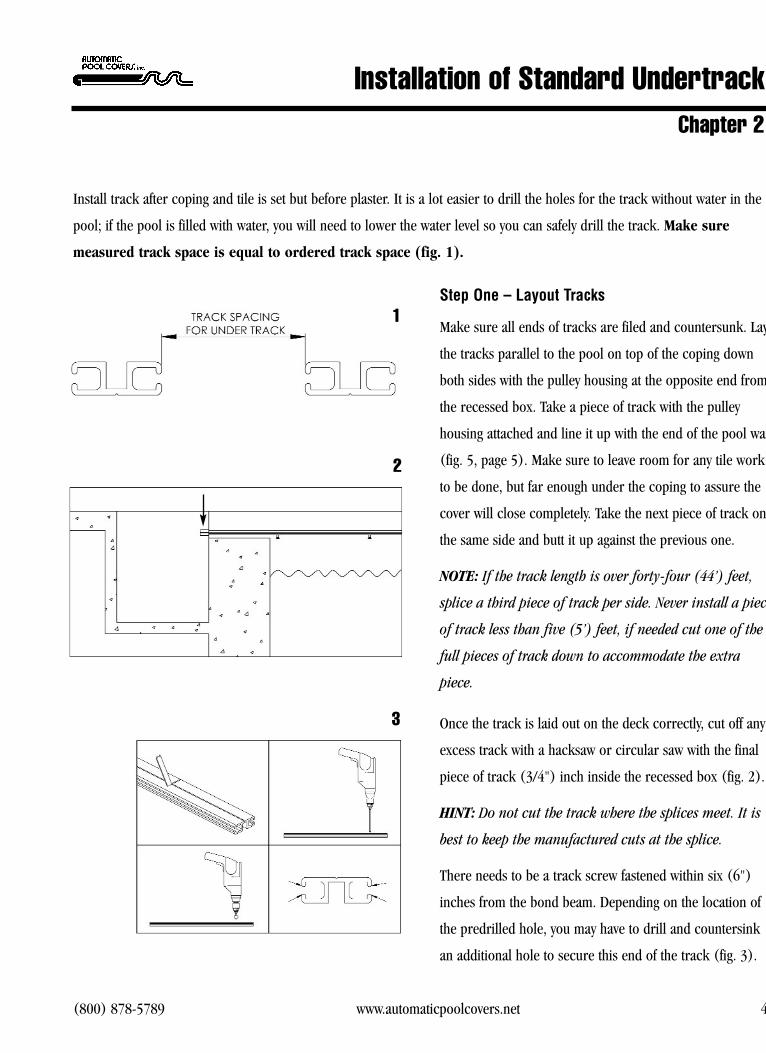
Step One � Layout Tracks
Make sure all ends of tracks are filed and countersunk. Lay
the tracks parallel to the pool on top of the coping down
both sides with the pulley housing at the opposite end from
the recessed box. Take a piece of track with the pulley
housing attached and line it up with the end of the pool wall
(fig. 5, page 5). Make sure to leave room for any tile work
to be done, but far enough under the coping to assure the
cover will close completely. Take the next piece of track on
the same side and butt it up against the previous one.
NOTE: If the track length is over forty-four (44’) feet,
splice a third piece of track per side. Never install a piece
of track less than five (5’) feet, if needed cut one of the
full pieces of track down to accommodate the extra
piece.
Once the track is laid out on the deck correctly, cut off any
excess track with a hacksaw or circular saw with the final
piece of track (3/4") inch inside the recessed box (fig. 2).
HINT: Do not cut the track where the splices meet. It is
best to keep the manufactured cuts at the splice.
There needs to be a track screw fastened within six (6")
inches from the bond beam. Depending on the location of
the predrilled hole, you may have to drill and countersink
an additional hole to secure this end of the track (fig. 3).
Installation of Standard Undertrack
Install track after coping and tile is set but before plaster. It is a lot easier to drill the holes for the track without water in the
pool; if the pool is filled with water, you will need to lower the water level so you can safely drill the track. Make sure
measured track space is equal to ordered track space (fig. 1).
Chapter 2
3
2
1

(800) 878-5789 www.automaticpoolcovers.net 5
Next, file and countersink all ends of the track to make sure
there are no sharp edges to rub on the rope or webbing.
Repeat the above steps for the other side of the pool.
Step Two � Clamp Tracks to Coping
Mount tracks under the coping with “C” clamps (fig. 4).
Start with the pulley housing piece of track at the far end
of the cover housing. Drill the track so the pulley housing
is under the coping (on the far end) leaving enough room
for any tile work (fig. 5). The edge of the track should be
flush with the edge of the coping down the entire pool
side. Insert the aluminum track splice where the two
tracks splice together. Clamp the tracks to the coping
making sure the splice is tight. If the tracks are uneven at
the splice, “shim” a track to align the rope channels.
Step Three � Drill Tracks
With the tracks clamped in place, use a hammer drill with
a 1/4" masonry drill bit. Drill holes in the coping to (2")
inches deep.
WARNING: Be careful not to drill through thin
coping or brick mortar. If holes in tracks are lined up
over mortar joints, drill hole using a regular drill with
1/4" masonry bit, not a hammer drill. If there are end
or corner steps to the pool, you may need to use an
angle drill to drill and secure the tracks above the step
area.
Installation of Standard UndertrackChapter 2
4
5

(800) 878-5789 www.automaticpoolcovers.net 6
Step Four � Track Screws and Anchors
It is important to assemble the track and anchor by
inserting the track screws into the red anchors (fig. 6).
It is easiest if you assemble all prior to starting to put into
the tracks. Tap in the screw and anchor assembly into the
track hole.
IMPORTANT: Anchor must be set into coping before
tapping into place to avoid breaking anchor.
Tap the anchor and screw assembly until the top of the
screw is 1/2" from the track.
Step Five � Tighten Track Screws
Use an electric or cordless drill with a #3 Phillips
screwdriver. Tighten track screws into the tracks. As you
tighten the screws be careful that you don’t go too fast and
crack the coping or burr the top of the track screw.
Continue on to the installation of the system.
6
Installation of Standard UndertrackChapter 2

(800) 878-5789 www.automaticpoolcovers.net 7
Step One � Layout Tracks
Lay the tracks parallel to the pool on top of the coping
down both sides with the pulley housing at the opposite
end from the recessed box. Take the next piece of track
on the same side and butt it up against the previous one.
The splice opening is always face up.
NOTE: If the track length is over forty-four (44') feet,
you will need to splice a third piece of track per side.
Never install a piece of track less than five (5') feet. If
needed, cut one of the full pieces of track down to
accommodate the extra piece.
The track needs to extend (3/4") inch into the recessed
box (fig.7). Once the track is laid out on the deck correctly,
cut off any excess track with a hacksaw or circular saw.
HINT: Do not cut the track where the splices meet. It is
best to keep the manufactured cuts at the splice. Cut
track at box end.
Make sure to file and countersink any new cuts to the
track. Repeat the above steps for the other side of the pool.
Installation of Retainer UndertrackChapter 2
Proceed to Installation of the AutoGuard System (Chapter 4), Steps One through Six, prior to beginning this chapter.
Once those steps are completed make sure the retainer is free of all debris (concrete, dirt, etc).
3/4"
7

(800) 878-5789 www.automaticpoolcovers.net 8
Step Two � Pulling Rope Through Tracks
With the track still on top of the deck, install the track
splice on both sides. Lay fabric out behind recessed box
with the topside (smooth side) up showing warning labels.
Uncoil both ropes and be careful not to tangle or knot.
Feed the end of the rope through the opposite side guide
leaving three (3') feet and then pull through the front
channel of the track (fig. 8). Install the guide into track.
Pull rope down to the far end of the track. Feed around
the track pulley assembly (fig. 9) while maintaining a
three (3') foot leader and down the backside channel of
the track through the back channel of the guide. Pull
excess rope through until the front of cover is touching the
guide. Repeat this step for the motor side track.
Step Three � Installing and Securing Track Into
Retainer
Make sure the retainer is clear of any concrete, dirt, etc.
and ready to install the undertrack. Once both ropes are
pulled through the tracks, lower the tracks and slide into
the retainer. Make sure the track placement is correct with
the overhang in the recessed box of (3/4") inch. Also,
make sure the track splices are together tightly with no
gap between the tracks. Remember the splice faces up
when inserting the track.
Installation of Retainer UndertrackChapter 2
8
9

(800) 878-5789 www.automaticpoolcovers.net 9
Starting at the pulley housing at the opposite end of the
pool, install the track wedges (fig. 10). Proceed inserting
wedges up to the guide: make sure splice is together
when installing wedges. Drill and install a (1/4") inch
bolt or long track screw (depending on the recessed box
type) through the track and into the retainer at the guide
end of the track. This is done to prevent the track from
moving while the cover is operating. This is vital to the
installation. Repeat the above steps for the other side
of track.
At this time, the track is completely installed. Return to
Step Seven A (7A) of the Installation of AutoGuard
System (Chapter 4) to complete the installation.
Installation of Retainer UndertrackChapter 2
10

(800) 878-5789 www.automaticpoolcovers.net 10
Step One � Layout Tracks
Make sure all ends of the tracks are filed and countersunk.
Measure from the inside front of the recessed box to the
opposite end of the pool and add two (2') feet for
overlap at the opposite end of the pool. This is the track
length. Layout the tracks on the sides of the pool, insert a
track splice and cut off any excess track with a hacksaw
or circular saw at the recessed box end (fig. 11). If any of
the track requires cutting, remember to file and counter-
sink again.
HINT: Do not cut the track where the splices will meet.
It is best to keep the manufactured cuts at the splice.
NOTE: If track length is over forty-four (44') feet, you
will need to splice a third piece of track per side. Never
install a piece of track less than five (5') feet. If needed,
cut one of the full pieces of track down to accommodate
the extra piece.
If the manufactured holes are cut off, drill new holes three
(3") inches from the track end and three (3") inches
from the splice end. Use a 1/4" drill bit and countersink
(fig. 12). Again, make sure all corners and edges are filed to
eliminate the rope or webbing from tearing.
Align the tracks with the inside edge of the recessed box
on both sides and measure the distance between the
tracks. This is your track space (fig. 13). Place the
Installation of ToptrackChapter 3
11
12
13
With the toptrack installation, the cover and extrusions are manufactured in accordance with the ordered track space. Thistrack space is measured from the track channels not the inside edges of the track (fig. 13).
(800) 878-5789 www.automaticpoolcovers.net 11
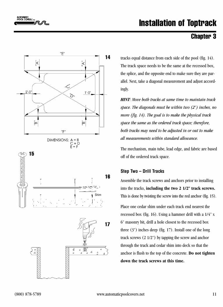
tracks equal distance from each side of the pool (fig. 14).
The track space needs to be the same at the recessed box,
the splice, and the opposite end to make sure they are par-
allel. Next, take a diagonal measurement and adjust accord-
ingly.
HINT: Move both tracks at same time to maintain track
space. The diagonals must be within two (2") inches, no
more (fig. 14). The goal is to make the physical track
space the same as the ordered track space; therefore,
both tracks may need to be adjusted in or out to make
all measurements within standard allowance.
The mechanism, main tube, lead edge, and fabric are based
off of the ordered track space.
Step Two � Drill Tracks
Assemble the track screws and anchors prior to installing
into the tracks, including the two 2 1/2" track screws.
This is done by twisting the screw into the red anchor (fig. 15).
Place one cedar shim under each track end nearest the
recessed box (fig. 16). Using a hammer drill with a 1/4" x
6" masonry bit, drill a hole closest to the recessed box
three (3") inches deep (fig. 17). Install one of the long
track screws (2 1/2") by tapping the screw and anchor
through the track and cedar shim into deck so that the
anchor is flush to the top of the concrete. Do not tighten
down the track screws at this time.
15
16
17
Installation of ToptrackChapter 3
14
Shim

(800) 878-5789 www.automaticpoolcovers.net 12
Make sure the track splice is snug together and walk
down to the opposite end and drill the last hole three (3")
inches deep and install track screw/anchor but do not
tighten down.
HINT: Stand on the track while drilling to prevent track
from shifting.
To keep the track straight, run a string down the track
from one end to the other and mark the deck with a pencil
or tape before drilling the remaining holes. Hammer drill
one (1) hole on each side of the track splice(s) and
install screws/anchors. Finish drilling and inserting
screws/anchors into remaining holes. Once this is complete,
follow the same steps for the opposite side track.
NOTE: If there is a slide, may require use of an angle
drill or angle attachment to drill holes under slide.
When all tracks are drilled and loosely secured with the
screws/anchors, go to the far end of the pool and insert
the pulley casting assembly into the end of the track. Tap
the top of the pulley casting to create a mark in the deck,
remove pulley casting and drill a 1/2" diameter hole
(3/4") inches deep on the mark (fig. 18) to recess the
pulley nut into the deck. Repeat this step on the other
side. Continue on to the installation of the system.
18
Installation of ToptrackChapter 3

(800) 878-5789 www.automaticpoolcovers.net 13
Notes:

(800) 878-5789 www.automaticpoolcovers.net 14
Step One � Attach Main Tube to End Castings
Using four (4) hex head cap screws (p/n HC-0019) and
(4) lock washers per end, attach the main tube to the
motor and opposite end castings with a 1/2" wrench (fig.
19).
Step Two � Install Mechanism
Set the mechanism inside the recessed box. Measure the
distance between the two tracks and find the halfway point
and mark it on the front of the recessed box. The mechanism
will have a line at the center point of the main tube. Align
the two marks and this will center the mechanism between
the track space (fig. 20).
Loosen the mounting bracket bolts (fig. 21) on the
mechanism and opposite end with a wrench so the bracket
can adjust in and out. Center the mechanism from front to
back (fig. 22). When the mechanism is aligned properly,
lightly tighten bracket bolts with wrench.
Toptrack installations: Raise the mechanism until the
top of the mounting bracket is flush to top of the
recessed box.
Undertrack installations: Raise the mechanism until
the top of the mounting bracket is level with top of
track.
Installation of AutoGuard SystemChapter 4
19
20
21
22

(800) 878-5789 www.automaticpoolcovers.net 15
Fasten the mounting brackets to the recessed box using
the appropriate hardware: self tap screws for metal boxes,
lag bolts or track screws for wood boxes, tapcons or track
screws/anchors for concrete boxes. Use three (3) screws
per bracket at motor end and two (2) per bracket on
opposite end, for a total of (6) screws at motor end and
(4) screws at opposite end.
NOTE: Be careful not to shift the mechanism from side
to side. Maintain the center line on the main tube and
front of recessed box at all times.
Step Three � Install Rope Eyelets
Measure the distance from the top of the recessed box
to the top of the mounting bracket. This is the eyelet
installation height. Install two eyelets on the backside of
the recessed box at least four (4’) feet from each end of
the main track (pic. 23).
Step Four � Install Track Guides and Sensors
Make sure sensors are installed into guides flush with top
of sensor plate. Tap guides into end of track at recessed
Installation of AutoGuard SystemChapter 4
23
24
(800) 878-5789 www.automaticpoolcovers.net 16
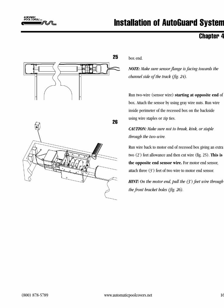
box end.
NOTE: Make sure sensor flange is facing towards the
channel side of the track (fig. 24).
Run two-wire (sensor wire) starting at opposite end of
box. Attach the sensor by using gray wire nuts. Run wire
inside perimeter of the recessed box on the backside
using wire staples or zip ties.
CAUTION: Make sure not to break, kink, or staple
through the two-wire.
Run wire back to motor end of recessed box giving an extra
two (2') feet allowance and then cut wire (fig. 25). This is
the opposite end sensor wire. For motor end sensor,
attach three (3') feet of two wire to motor end sensor.
HINT: On the motor end, pull the (3') feet wire through
the front bracket holes (fig. 26).
Installation of AutoGuard SystemChapter 4
25
26
(800) 878-5789 www.automaticpoolcovers.net 17
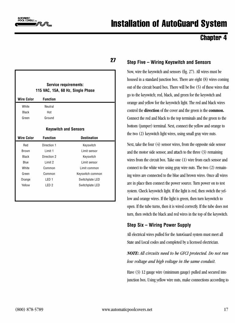
Step Five � Wiring Keyswitch and Sensors
Now, wire the keyswitch and sensors (fig. 27). All wires must be
housed in a standard junction box. There are eight (8) wires coming
out of the circuit board box. There will be five (5) of these wires that
go to the keyswitch; red, black, and green for the keyswitch and
orange and yellow for the keyswitch light. The red and black wires
control the direction of the cover and the green is the common.
Connect the red and black to the top terminals and the green to the
bottom (jumper) terminal. Next, connect the yellow and orange to
the two (2) keyswitch light wires, using small gray wire nuts.
Next, take the four (4) sensor wires, from the opposite side sensor
and the motor side sensor, and attach to the three (3) remaining
wires from the circuit box. Take one (1) wire from each sensor and
connect to the white wire using gray wire nuts. The two (2) remain-
ing wires are connected to the blue and brown wires. Once all wires
are in place then connect the power source. Turn power on to test
system. Check keyswitch light. If the light is red, then switch the yel-
low and orange wires. If the light is green, then turn keyswitch to
open. If the tube turns, then it is wired correctly. If the tube does not
turn, then switch the black and red wires in the top of the keyswitch.
Step Six � Wiring Power Supply
All electrical wires pulled for the AutoGuard system must meet all
State and Local codes and completed by a licensed electrician.
NOTE: All circuits need to be GFCI protected. Do not run
low voltage and high voltage in the same conduit.
Have (3) 12 gauge wire (minimum gauge) pulled and secured into
junction box. Using yellow wire nuts, make connections according to
27
Service requirements: 115 VAC, 15A, 60 Hz, Single Phase
Wire Color Function
White Neutral
Black Hot
Green Ground
Keyswitch and Sensors
Wire Color Function Destination
Red Direction 1 Keyswitch
Brown Limit 1 Limit sensor
Black Direction 2 Keyswitch
Blue Limit 2 Limit sensor
White Common Limit common
Green Common Keyswitch common
Orange LED 1 Switchplate LED
Yellow LED 2 Switchplate LED
Installation of AutoGuard SystemChapter 4

(800) 878-5789 www.automaticpoolcovers.net 18
Step Seven � Install Cover Fabric
Lay fabric out behind recessed box with the topside
(smooth side) up showing warning labels. Uncoil both
ropes and be careful not to tangle or knot. Remove guide
from opposite side of track and feed the end of the rope
through the sensor side of the guide leaving three (3') feet
and then pull through the front channel of the track
(fig. 28A and 28B). Reinstall the guide into track.
Pull rope down to the far end of the pool. Feed around the
track pulley assembly (fig. 29A and 29B) while maintaining
a three (3') foot leader and down the backside channel of
the track through the back channel of the guide. Pull excess
rope through until the front of cover is touching the guide.
Step Seven A
Feed opposite end rope around the opposite end pulley
in the recessed box, then run rope through both eyelets on
the back of the recessed box and all three pulleys on the
motor side pulley bar laying remaining rope on deck
(fig. 30 & 37). Next, pull the motor side rope through the
tracks using the above steps. When you have the rope back
at the recessed box, pull the rope through the first two
pulleys only on the motor side pulley bar and lay
remaining rope on deck. Secure the track screws using a
#3 Philips head bit. Be careful not to strip the heads of the
screws. Pull the ropes tight so both corners of cover are
Installation of AutoGuard SystemChapter 4
28
28A
29 29A
30

(800) 878-5789 www.automaticpoolcovers.net 19
tight against the guides and measure approximately eight
(8') feet from the pulleys. Cut the ropes equally.
Immediately, use a cigarette lighter to melt the ends of the
ropes to prevent fraying.
If job has gliders, install gliders at this time. Lay out the
right and left gliders next to the appropriate guides
(fig.34). Make sure the glider corners are filed so the
rope will slide into the glider easily. Pull the cover into the
guide, then carefully pull the guide apart from the track
and slide the glider onto the rope in front of the
cover/guide (fig. 31). Install the glider flush with the
cover and reinstall the guide into the track. Drill a 5/32"
hole through the track and guide 1/4" from the end of the
track. Install the guide screw (fig. 32). Repeat the above
steps on the other side.
Step Eight � Install Lead Edge Bar
Pull one side of fabric into the track approximately one
(1') foot. Make sure the lead edge bar is right side up
with the four holes on top. Make sure that the lead edge
channel ends are filed. Slide the lead edge bar completely
across the front of the cover (fig. 33).
HINT: The front of the cover needs to be tight for the
lead edge to slide on easily.
Next pull the other front corner of the cover into the
track approximately one (1') foot making both sides even
Installation of AutoGuard SystemChapter 4
31
32
33
34
RightLeft

(800) 878-5789 www.automaticpoolcovers.net 20
(fig. 34).
When installing an undertrack system, slide the lead edge
bar onto the front of the cover and into glider dowel on
other side. Reinstall fabric into the guide and slide other
dowel into lead edge bar.
On a toptrack installation, flip the lead edge bar back
onto the cover and secure the dowel and lead edge with a
#10 x 1/2" Phillips screw on the bottom side of the lead
edge bar. Flip lead edge bar back over and secure fabric
to the lead edge bar using the predrilled holes (fig. 35).
The holes should be centered between the white
corner gusset. Do not fasten dowel to the lead edge bar
on undertrack systems.
NOTE: Distribute the extra cover material evenly across
the lead edge bar (fig. 36).
Step Nine � Pulling Fabric Onto Pool
Make sure lead edge bar is perpendicular with the tracks
and pull the ropes to equal lengths.
IMPORTANT: Make sure fabric is straight across pool.
If not, ropes will be different lengths, causing cover to
run crooked.
Attach both ropes one (1") inch from rope end to the
rope reels using the screws in the predrilled holes
(fig. 37). Double check making sure to attach the
rope to the correct rope reel. It is now time to close
Installation of AutoGuard SystemChapter 4
35
36
37

(800) 878-5789 www.automaticpoolcovers.net 21
the cover.
EXTREME CAUTION: Keep fingers clear of ropes and
pulleys while operating.
Turn key switch to close and ease ropes onto rope reels.
This will help the ropes lay flat across the bottom of the
reel and not stack up on one side.
Once the excess rope is on the reels, the cover will start to
pull across the pool. Watch both sides of the cover to make
sure the cover is operating properly. Stop the cover approxi-
mately two (2’) feet from the end of the pool.
Step Ten - Install Auto Shut Off Magnets
Take a magnet and pass it over the motor side sensor. Turn
the keyswitch to close. If the cover moves, then the motor
side sensor is the open sensor. If the cover does not move,
the motor side sensor is the close sensor. Once this is
determined, install the sensor magnets. The open sensor
magnet will go in the front of the cover on the open
sensor side. The close sensor magnet will go on the close
sensor side in the back of the cover on the opposite side.
NOTE: The magnets will travel approximately one (1")
inch past the sensor before the cover stops. Take this into
consideration when installing the magnets.
Once the cover is open, the open magnet will need to slide
into the webbing and pushed in from front of cover approxi-
mately 4" to 5" (inches) (fig. 38A and 38B). This is impor-
tant because it will keep the cover from opening too far into
38A
38B
39
Installation of AutoGuard SystemChapter 4

(800) 878-5789 www.automaticpoolcovers.net 22
the recessed box or
coming out of the track and guide. The back close magnet
should be set when the cover is closed. Stop the cover at
handrail or before it hits the pulley castings at the end of the
tracks. After closing the cover to the desired stopping point,
cut a slit in the webbing eight (6”) inches behind the guide
and slide the close magnet into the webbing (fig. 39).
Step Eleven � Attaching Cover to Main Tube
The main tube is predrilled from the factory for ease of
attaching the cover to the main tube. All screws will be one
(1") inch from the back end of the cover. Start first screw
one (1") inch from the back end of cover and next to
webbing (fig. 40). Attach cover using #10 x 1/2" Phillips
screws. The extra fabric will be spread out across the
main tube evenly. There should be 3" to 4" (inches)of
slack on each side of the centerline of the tube. Now open
the cover.
NOTE: Make sure on the first opening of the cover that
the magnet stops the cover properly.
Run cover 3 to 4 times out and back to make sure your
magnets are set properly and cover is running square to
pool. If cover is opening crooked, it needs to be adjusted.
When opening cover, the side that returns first is the side
that needs the rope shortened. The distance that it is off is
the amount that you need to adjust. For example, if the
motor side returns three (3") inches before the opposite
40
41
Installation of AutoGuard SystemChapter 4

(800) 878-5789 www.automaticpoolcovers.net 23
side, the motor side rope needs to be shortened three
(3") inches (fig. 41). This is accomplished by removing
both ropes from the rope reels and removing the motor
side rope reel screw. Refasten the screw three (3") inches
up on the rope and reattach to rope reel. Roll ropes back
onto rope reels and run cover. If the opposite side of the
cover returns first when opening, do the same procedure
on the opposite side rope.
Step Twelve - Install Main Lid Assembly
The lid hinge must first be slid onto the main lid. Install
the lid bracket holders, next install the lid brackets. Space
them evenly with the two (2) outside brackets one (1')
foot in
from the tracks (fig. 42). Level the back of the bracket
extension with the deck height. Use track screws to mount
bracket holders in a wood box. Track screws & anchors
on a concrete housing, self tap or tapcons on a metal box.
Lay the lid and lid hinge (lid assembly) on the top of the
lid brackets centering the assembly between the tracks.
Make sure it is equal distance on both sides of the tracks.
Make sure the lid assembly covers the front and back of
the box (fig. 43). Also, make sure the hinge covers both
ends of the box by approximately one (1") inch. Cut any
extra hinge with a hacksaw or circular saw. File both
ends of the hinge to make sure there are no sharp
edges or burrs. Drill 1/4" holes thru the lid hinge so the
holes line up with the wood box (if applicable). Place a
43
44
45
Installation of AutoGuard SystemChapter 4
Lid Screws

(800) 878-5789 www.automaticpoolcovers.net 24
screw 3" to 4" (inches) from each end of the hinge, then
space the holes every four (4') feet (fig. 44). Secure lid
hinge with screws and/or anchors depending on wood or
concrete. File the ends of the main lid and center the
lid again over the tracks.
If the job is a top track, it is time to install the lid
triangles. Flip the motor side lid end over and install one
of the lid triangles with (2) #10 x 1/2" Phillips screws
(fig. 45). Reinstall the lid end, mark and cut to length
using a jigsaw or circular saw. Repeat the same steps for
installing the opposite side lid end and lid triangle. Double
check to make sure the lid hinge, the lid ends, and main
lid are filed thoroughly and do not have any sharp edges.
If the job is an undertrack, center the lid over the
tracks and slide both the long and short lid ends onto the
46
THE JOB IS DONE. CONGRATULATIONS !!
Installation of AutoGuard SystemChapter 4

(800) 878-5789 www.automaticpoolcovers.net 25
Instructing the CustomerChapter 5
After completing your installation, it is extremely important
to instruct the owner on the proper operation and
maintenance of their pool cover. This will insure complete
customer satisfaction for years to come as well as maximizing
your profits by avoiding costly call-backs due to improper
operation. All of the instruction information needed to
explain the proper use of a pool cover can be found in the
owner’s manual provided with every system.
Automatic Pool Covers, Inc. places a lot of emphasis on
the owner’s understanding of the operation of their new
pool cover. If we can be of assistance, please contact us
toll free at (800)-878-5789.
Please fill out the “Completion Checklist” with the home-
owner and return a copy to Automatic Pool Covers, Inc.

(800) 878-5789 www.automaticpoolcovers.net 26
n Never leave a child unsupervised in or near a pool.
n Teach children to float or swim as soon as possible.
n Instruct family and babysitters of potential hazards in andaround the pool.
n Fence the pool area with self locking/closing gates withlatches out of reach of young children.
n Do not consider children “drown proof” because they havehad swimming lessons.
n Flotation devices are not a substitute for supervision.
n Never use a pool with the pool cover partially opened.
n Remove cover completely prior to getting into pool.
n Keep toys away from pool area to prevent children fromaccidentally falling into pool while playing.
n Have a telephone with emergency numbers near the pool area.
n Keep rescue equipment and first aid supplies near the pool.
n Have all caretakers trained in cardiopulmonary resuscitation (CPR) and first aid.
n No one should ever swim alone – even adults!
n Teach children what to do in case of an emergency.
n Caution all swimmers against showing off, playing rough,and the dangers of running and diving recklessly, pushingor dunking others in the pool.
n Keep all electrical appliances such as a radio away fromthe pool area. Make sure electrical work meets standardsand are GFCI protected.
n Inspect pool cover and other equipment to maintain optimum effectiveness. Yearly inspection by a professionalis recommended.
n When pool is not in use, close the cover completely.
n Remember animals and pets need to be protected also.
n Keep all doors and windows leading from the house to thepool area closed and locked to prevent children from slipping out of sight.
n Make sure to remove all standing water from the poolcover top. Drowning can occur in only a few inches ofwater.
n Never let anyone swim after drinking alcoholic beverages,eating, or taking medications.
n Make sure family and friends understand the importance ofpool safety and adhere to all pool safety rules.
n Think smart and have fun!
Sources: United States Consumer Product Safety Commission; National Spa &Pool Institute.
While we strive to continually make our AutoGuard automatic pool cover one of the best forms of pool
safety, we believe there is no substitute for constant adult supervision. Most drownings can
occur in less than five minutes. Therefore, we suggest layers of protection and barriers to reduce the
risks if a child were to step out of vision from the child’s caretaker. The following are som e
suggestions for safety in and around your pool so you and your family can get the maximum enjoyment
from your pool and pool cover.
Safety ChecklistChapter 5

(800) 878-5789 www.automaticpoolcovers.net 27
1. Can I walk on the cover? Yes, but recommended only in an emergency.
2. Is the cover too big? The fabric is manufactured to include extra material for winterization. Initially, the fabric could appear wrinkled or oversized but these wrinkles are normal and may smooth out.
3. Can the cover be opened/closed manually? Yes, it can. It will take (2) people. the cover will need to be pulled off by hand or pulled on by pulling the two ropes.Please contact your service representative for instruction.
4. Can I run the cover without water in the pool? No. The cover can run only with a water level at a maximumof 2" below the skimmer. The fabric must be supported by
water in the pool.
5. Can I adjust the cover if it opens or Yes. See chapter 4, step 11 for cover adjustment. If cover closes crooked? opens straight and is closing crooked, you will need to
add rope to the reel that needs to close further. Call for assistance.
AnswersQuestions
Frequently Asked QuestionsChapter 6

The cover does not open when I turn the key. n Is the green keyswitch indicator light on? If not, you do not have power to the system. Check your electrical service.
n If the motor is turning and nothing is happening, you might need mechanical service. Please contact your installationcompany for possible repairs.
n If the motor just hums, and does not turn. Call for service.
Water appears on my cover when it has not rained n Your cover probably has a hole somewhere and needs to bein days. patched. Contact your installation company. They can send
you a patch kit to easily fix the problem.
The cover stops half way closed/opened. n The tracks might have dirt or debris inside. Clean the tracks out with water.
n The ropes could be tangled around the rope reel. Lift the lid and check the reels. If the rope appears tangled, you can try to untangle it yourself (be careful!) or call for service.
n Automatic Shut-Off (ASO) could be malfunctioning. Call for service.
The keyswitch indicator light is blinking red. n This means the cover has stopped under stress. There might be too much water on the cover. The cover could be runningtoo crooked or there could be an object blocking the cover. Remove the water or blocking object. If red light continues to blink, call for service.
The cover is completely open and will not close. n The cover might have opened too far and come out of the track. Call for service.
n Is the green keyswitch indicator light on? If not, you do not have power to the system. Check your electrical service.
Submersible cover pump is not pumping off n The Automatic Shut-Off (ASO) might be malfunctioning. the water. Disconnect the dual plugs at the outlet and plug the smaller
plug into the outlet. This will operate the pump without Automatic Shut-Off. If the pump works, then the problem is the ASO, and it should be replaced. If the problem is not the ASO, then the pump needs to be replaced.
(800) 878-5789 www.automaticpoolcovers.net 28
Diagnostics Service InformationChapter 6