TABLE OF CONTENTS PART 5 – MAINTENANCE - …downloads.transportation.org/SCOH-16-07 Movable...
86
PART 5 – MAINTENANCE 5-i ©2016 by the American Association of State Highway and Transportation Officials All rights reserved. Duplication is a violation of applicable law. SECTION 5 – TABLE OF CONTENTS PART 5 – MAINTENANCE PART 5 – MAINTENANCE ...................................................................................................................................... 5-i CHAPTER 5.1 – MOVABLE BRIDGE MAINTENANCE ..................................................................................... 5-1 5.1.1 GENERAL........................................................................................................................................... 5-1 5.1.2 MAINTENANCE OBJECTIVES AND GOALS .................................................................................... 5-1 5.1.3 MAINTENANCE ACTIVITIES ............................................................................................................. 5-2 5.1.3.1 Component Failure Maintenance (Repairs) ................................................................................... 5-2 5.1.3.2 Preventive Maintenance ................................................................................................................. 5-3 5.1.4 ESSENTIALS OF A MAINTENANCE PROGRAM ............................................................................. 5-3 CHAPTER 5.2 – STRUCTURAL MAINTENANCE ............................................................................................. 5-5 5.2.1 GENERAL........................................................................................................................................... 5-5 5.2.2 STRUCTURAL CONCRETE .............................................................................................................. 5-5 5.2.3 STRUCTURAL STEEL ....................................................................................................................... 5-6 5.2.4 STRUCTURAL TIMBER ..................................................................................................................... 5-7 5.2.5 MACHINERY SUPPORTS AND FRAMES ........................................................................................ 5-8 5.2.6 FASTENERS ...................................................................................................................................... 5-8 5.2.7 SHIP LADDERS, WALKWAYS, AND PLATFORMS.......................................................................... 5-9 5.2.8 COUNTERWEIGHT AND COUNTERWEIGHT PIT ........................................................................... 5-9 5.2.9 FENDER SYSTEM AND OTHER PIER PROTECTIVE DEVICES .................................................... 5-9 5.2.10 OPERATOR’S (TENDER’S) HOUSE ............................................................................................... 5-10 5.2.11 STEEL GRID DECKS ....................................................................................................................... 5-11 5.2.12 OTHER DECKS ................................................................................................................................ 5-11 CHAPTER 5.3 – MECHANICAL MAINTENANCE............................................................................................ 5-12 5.3.1 GENERAL........................................................................................................................................... 5-12 5.3.2 LUBRICATION.................................................................................................................................... 5-12 5.3.2.1 Lubrication Chart .......................................................................................................................... 5-13 5.3.3 MECHANICAL COMPONENTS ......................................................................................................... 5-14 5.3.4 BEARINGS ......................................................................................................................................... 5-15 5.3.5 SHAFTS.............................................................................................................................................. 5-16 5.3.6 COUPLINGS....................................................................................................................................... 5-16 5.3.7 ENCLOSED GEARS .......................................................................................................................... 5-17 5.3.8 OPEN GEARS .................................................................................................................................... 5-18 5.3.9 BRAKES ............................................................................................................................................. 5-19 5.3.10 BUFFER CYLINDERS ...................................................................................................................... 5-20 5.3.11 AUXILIARY POWER ........................................................................................................................ 5-20 5.3.12 LIVE LOAD SHOES AND STRIKE PLATES .................................................................................... 5-21 5.3.13 FASTENERS .................................................................................................................................... 5-22 5.3.14 SUMP PUMPS.................................................................................................................................. 5-22 5.3.15 END JACKS, CENTER WEDGES, SPAN LOCKS, AND OTHER SPECIAL MACHINERY ............ 5-22 5.3.16 WIRE ROPES ................................................................................................................................... 5-23 5.3.17 BALANCE WHEELS ......................................................................................................................... 5-23 5.3.18 SUPPORT ROLLERS ...................................................................................................................... 5-24 5.3.19 MAINTENANCE LUBRICATION LOG.............................................................................................. 5-24 5.3.20 SAMPLE LUBRICATION CHART .................................................................................................... 5-25 5.3.21 OPERATOR’S (TENDER’S) HOUSE ............................................................................................... 5-30 CHAPTER 5.4 – HYDRAULIC MAINTENANCE .............................................................................................. 5-31 5.4.1 GENERAL........................................................................................................................................... 5-31 5.4.2 HYDRAULIC COMPONENTS ............................................................................................................ 5-31 5.4.3 ACCUMULATORS.............................................................................................................................. 5-31 5.4.4 VALVES .............................................................................................................................................. 5-32 5.4.5 HYDRAULIC CYLINDERS ................................................................................................................. 5-34 5.4.6 HYDRAULIC PUMPS ......................................................................................................................... 5-36 5.4.7 HYDRAULIC MOTORS AND ROTARY ACTUATORS ...................................................................... 5-40
Transcript of TABLE OF CONTENTS PART 5 – MAINTENANCE - …downloads.transportation.org/SCOH-16-07 Movable...

PART 5 – MAINTENANCE
5-i ©2016 by the American Association of State Highway and Transportation Officials
All rights reserved. Duplication is a violation of applicable law.
SECTION 5 – TABLE OF CONTENTS PART 5 – MAINTENANCE PART 5 – MAINTENANCE ...................................................................................................................................... 5-i
CHAPTER 5.1 – MOVABLE BRIDGE MAINTENANCE ..................................................................................... 5-1 5.1.1 GENERAL ........................................................................................................................................... 5-1 5.1.2 MAINTENANCE OBJECTIVES AND GOALS .................................................................................... 5-1 5.1.3 MAINTENANCE ACTIVITIES ............................................................................................................. 5-2 5.1.3.1 Component Failure Maintenance (Repairs) ................................................................................... 5-2 5.1.3.2 Preventive Maintenance ................................................................................................................. 5-3
5.1.4 ESSENTIALS OF A MAINTENANCE PROGRAM ............................................................................. 5-3 CHAPTER 5.2 – STRUCTURAL MAINTENANCE ............................................................................................. 5-5
5.2.1 GENERAL ........................................................................................................................................... 5-5 5.2.2 STRUCTURAL CONCRETE .............................................................................................................. 5-5 5.2.3 STRUCTURAL STEEL ....................................................................................................................... 5-6 5.2.4 STRUCTURAL TIMBER ..................................................................................................................... 5-7 5.2.5 MACHINERY SUPPORTS AND FRAMES ........................................................................................ 5-8 5.2.6 FASTENERS ...................................................................................................................................... 5-8 5.2.7 SHIP LADDERS, WALKWAYS, AND PLATFORMS .......................................................................... 5-9 5.2.8 COUNTERWEIGHT AND COUNTERWEIGHT PIT ........................................................................... 5-9 5.2.9 FENDER SYSTEM AND OTHER PIER PROTECTIVE DEVICES .................................................... 5-9
5.2.10 OPERATOR’S (TENDER’S) HOUSE ............................................................................................... 5-10 5.2.11 STEEL GRID DECKS ....................................................................................................................... 5-11 5.2.12 OTHER DECKS ................................................................................................................................ 5-11
CHAPTER 5.3 – MECHANICAL MAINTENANCE............................................................................................ 5-12 5.3.1 GENERAL ........................................................................................................................................... 5-12 5.3.2 LUBRICATION .................................................................................................................................... 5-12
5.3.2.1 Lubrication Chart .......................................................................................................................... 5-13 5.3.3 MECHANICAL COMPONENTS ......................................................................................................... 5-14 5.3.4 BEARINGS ......................................................................................................................................... 5-15 5.3.5 SHAFTS .............................................................................................................................................. 5-16 5.3.6 COUPLINGS ....................................................................................................................................... 5-16 5.3.7 ENCLOSED GEARS .......................................................................................................................... 5-17 5.3.8 OPEN GEARS .................................................................................................................................... 5-18 5.3.9 BRAKES ............................................................................................................................................. 5-19 5.3.10 BUFFER CYLINDERS ...................................................................................................................... 5-20 5.3.11 AUXILIARY POWER ........................................................................................................................ 5-20 5.3.12 LIVE LOAD SHOES AND STRIKE PLATES .................................................................................... 5-21 5.3.13 FASTENERS .................................................................................................................................... 5-22 5.3.14 SUMP PUMPS .................................................................................................................................. 5-22 5.3.15 END JACKS, CENTER WEDGES, SPAN LOCKS, AND OTHER SPECIAL MACHINERY ............ 5-22 5.3.16 WIRE ROPES ................................................................................................................................... 5-23 5.3.17 BALANCE WHEELS ......................................................................................................................... 5-23 5.3.18 SUPPORT ROLLERS ...................................................................................................................... 5-24 5.3.19 MAINTENANCE LUBRICATION LOG.............................................................................................. 5-24 5.3.20 SAMPLE LUBRICATION CHART .................................................................................................... 5-25 5.3.21 OPERATOR’S (TENDER’S) HOUSE ............................................................................................... 5-30
CHAPTER 5.4 – HYDRAULIC MAINTENANCE .............................................................................................. 5-31 5.4.1 GENERAL ........................................................................................................................................... 5-31 5.4.2 HYDRAULIC COMPONENTS ............................................................................................................ 5-31 5.4.3 ACCUMULATORS.............................................................................................................................. 5-31 5.4.4 VALVES .............................................................................................................................................. 5-32 5.4.5 HYDRAULIC CYLINDERS ................................................................................................................. 5-34 5.4.6 HYDRAULIC PUMPS ......................................................................................................................... 5-36 5.4.7 HYDRAULIC MOTORS AND ROTARY ACTUATORS ...................................................................... 5-40

PART 5 – MAINTENANCE
5-ii ©2016 by the American Association of State Highway and Transportation Officials
All rights reserved. Duplication is a violation of applicable law.
5.4.8 FILTERS ............................................................................................................................................. 5-40 5.4.9 RIGID PIPING AND TUBING ............................................................................................................. 5-42 5.4.10 HYDRAULIC HOSE .......................................................................................................................... 5-43 5.4.11 RESERVOIRS .................................................................................................................................. 5-44 5.4.12 HYDRAULIC FLUIDS ....................................................................................................................... 5-45 5.4.13 HYDRAULIC SYSTEM INTERLOCKING SENSORS AND CONTROLS ........................................ 5-47 5.4.14 HYDRAULIC SYSTEM CHECK OUT ............................................................................................... 5-48
CHAPTER 5.5 – ELECTRICAL MAINTENANCE ............................................................................................. 5-53 5.5.1 GENERAL ........................................................................................................................................... 5-53 5.5.2 ELECTRIC MOTORS ......................................................................................................................... 5-53 5.5.3 MOTOR CONTROL COMPONENTS ................................................................................................. 5-54 5.5.4 GROUNDING ..................................................................................................................................... 5-55 5.5.5 LIGHTING, SIGNALS AND WARNING DEVICES ............................................................................. 5-56 5.5.6 AUXILIARY POWER .......................................................................................................................... 5-57 5.5.7 OPERATOR’S (TENDER’S) HOUSE ................................................................................................. 5-57
CHAPTER 5.6 – MAINTENANCE RECORDS & REPORTING ....................................................................... 5-58 5.6.1 GENERAL ........................................................................................................................................... 5-58 5.6.2 PURPOSE OF MAINTENANCE RECORDS ...................................................................................... 5-58 5.6.3 CONTENT OF MAINTENANCE RECORDS ...................................................................................... 5-58 5.6.4 SAMPLE FORMS AND THEIR USE .................................................................................................. 5-59
5.6.4.1 Bridge Operator’s (Tender’s) Forms, Logs, and Checklists ......................................................... 5-59 5.6.4.2 Bridge Operator’s (Tender’s) Reports .......................................................................................... 5-59 5.6.4.3 Maintenance Reports ................................................................................................................... 5-60

PART 5 – MAINTENANCE COMMENTARY
5-1 ©2016 by the American Association of State Highway and Transportation Officials
All rights reserved. Duplication is a violation of applicable law.
CHAPTER 5.1 – MOVABLE BRIDGE MAINTENANCE
5.1.1 GENERAL Bridge maintenance is defined as those activities necessary to
preserve the existing serviceability of the structure and to maintain a level of acceptable performance. For a movable bridge these activities should, as a minimum, include: inspection, testing, cleaning, lubrication, aligning, painting, component adjustment, and parts replacement. Carrying out these activities effectively involves a coordinated effort of collecting and analyzing condition data of the bridge, scheduling routine maintenance, prioritizing the special maintenance tasks required, allocating the necessary equip-ment, and using trained personnel to perform the tasks.
C5.1.1 A movable bridge represents a substantial
financial investment, not only in terms of initial cost of design and construction, but also in the annual costs required for inspection, main-tenance, and upkeep. The inherent complexity of the structure, coupled with often limited resources available to bridge owners to maintain these structures, provide justification for developing a cost effective maintenance program.
A movable bridge maintenance program is a vital component of an effective bridge management program. A properly executed maintenance program based on frequent inspections and continuous preventive maintenance practices provides protection not only for the bridge owner, but for the general public as well. The cost of such a program is small relative to the cost of major repair, rehabilitation or unscheduled bridge closure.
5.1.2 MAINTENANCE OBJECTIVES AND GOALS The objective of a maintenance program is to keep the
structure in good operating condition. A properly designed maintenance program can extend the operational life of the bridge, reduce unscheduled repairs, eliminate unsafe conditions, and increase the performance reliability. The specific goals of such a program should emphasize: • Developing a maintenance team comprised of properly
trained and equipped personnel capable of carrying out maintenance objectives in an efficient and economical manner.
• Establishing desired levels of maintenance service, including performance of scheduled testing, inspection, preventive maintenance, component adjustment for wear, and routine parts replacement in a consistent and timely manner to maintain reliable performance of the structure as designed.
• Providing component failure maintenance actions to replace worn or failed parts in a timely manner to minimize unscheduled downtime.

PART 5 – MAINTENANCE COMMENTARY
5-2 ©2016 by the American Association of State Highway and Transportation Officials
All rights reserved. Duplication is a violation of applicable law.
CHAPTER 5.1 – MOVABLE BRIDGE MAINTENANCE
• Providing a method by which management can evaluate planned versus actual performance and develop corrective procedures as required.
5.1.3 MAINTENANCE ACTIVITIES
Generally there are two primary maintenance activities that should be used on a movable bridge: component failure maintenance and preventive maintenance. Component failure maintenance is a responsive action to a failed system or component. Preventive maintenance involves regularly scheduled, planned activities that are intended to maintain functional systems and components in a normal operating condition. A preventive maintenance program encompasses regular evaluation and/or prediction of useful life of functional systems and components to detect and/or anticipate potential problems and schedule corrective action before a component failure occurs.
A description of various bridge and component testing procedures and advanced inspection methods is provided in Chapter 2.10.
C5.1.3 The underlying concept of an effective bridge maintenance program is not so much based on the level of effort and sophistication of the maintenance activities, but more the timing and proper implementation of these activities. The “worst first” approach, where attention is continuously focused on addressing the needs of the component or system in the worst condition, may suffice for the short term. However, in the long run this approach is ineffective due to the high cost of constant repair and replacement. Alternatively, preventive maintenance tasks such as cleaning, lubricating, painting, and performance testing, which extend component life and are carried out on a regular basis, can be more effective from a performance and cost standpoint than the resulting costs of replacement due to unexpected component failure.
5.1.3.1 Component Failure Maintenance (Repairs) Component failure maintenance activities are intended to
restore the bridge to an acceptable level of operation as quickly as possible in the event of unexpected system or component failure.
Component failure maintenance is responsive and can be costly when compared to planned preventive maintenance, but certain steps can be implemented to reduce this undesirable effect, as follows: • Establish contingency plans that outline the necessary steps
to restore the bridge to service, including: a contact list of key engineering and maintainers, a notification list of affected government and emergency response agencies, pre-approved bridge detour plans, and standard repair or retrofit procedures for probable failure events.
• Maintain a spare parts inventory of components. Critical, long lead time components whose failure could result in bridge closure should be kept on hand to minimize unacceptable delays. Consideration should also be given to stocking other noncritical components that require a long

PART 5 – MAINTENANCE COMMENTARY
5-3 ©2016 by the American Association of State Highway and Transportation Officials
All rights reserved. Duplication is a violation of applicable law.
CHAPTER 5.1 – MOVABLE BRIDGE MAINTENANCE
lead time for delivery. • Establish “on-call” contracts to expedite special
engineering and supplier or contractor services. • Establish a list of special manufacturers, machine shops,
and fabricators with “on-call” contracts for replacement or duplication of unique parts.
5.1.3.2 Preventive Maintenance
The objective of a preventive maintenance program is to
continually maintain the components in a state of good repair so that component failure would be very unlikely. To accomplish this objective, maintainer responsibilities should include: • Cleaning, lubricating, painting, and adjusting bridge
components and systems to maintain acceptable levels of operation under service conditions.
• Periodic inspection and performance testing of structural, mechanical, hydraulic and electrical components in a manner such that potential problems are discovered and corrective action is taken in a timely manner.
• Observation of the functional systems and components under various conditions of operation in order to increase understanding of the performance of the bridge.
• Performing maintenance on a regularly scheduled basis to minimize deterioration and/or wear.
• Replacing components or parts on a regularly scheduled basis.
• Proper record keeping and documentation of maintenance activities and testing results to permit performance evaluation and “fine tuning” of the system.
C5.1.3.2 The ideal preventive maintenance program,
which eliminates component failure mainte-nance, is difficult to implement on complex machinery designed without redundancy when useful life data on components is scarce or nonexistent. Reliable prediction of useful life data for critical components is a worthwhile goal because maintenance activity can be based upon cyclical replacement of these components prior to a well documented predicted failure date.
In cases where the life of critical components is not predictable, owners should be prepared to replace failures rapidly by stocking parts and having trained maintainers “on-call” to minimize bridge downtime.
5.1.4 ESSENTIALS OF A MAINTENANCE PROGRAM Maintenance Manual: A bridge-specific maintenance manual is preferred to be developed for use by maintainers to accomplish both component failure and preventive maintenance tasks. Some owners may find it appropriate to develop a more general manual that covers procedures at more than one structure of a particular type. Documentation should include written, graphical, and pictorial data that defines the maintenance and repair procedures for the various systems or components, including information on routine preventive maintenance activities for the various bridge components, tools and testing equipment, acceptable tolerances, safety procedures, repair/replacement parts, and a step-by-step sequence required to complete the maintenance or repair work.
C5.1.4 Manuals, training, and other essentials are
simplified if owners develop standard proce-dures for similar systems on similar movable bridges. Where feasible, standardization is useful because some or all parts can be inter-changeable from one bridge to another, sim-plifying and reducing the needs for stocking critical replacement components.

PART 5 – MAINTENANCE COMMENTARY
5-4 ©2016 by the American Association of State Highway and Transportation Officials
All rights reserved. Duplication is a violation of applicable law.
CHAPTER 5.1 – MOVABLE BRIDGE MAINTENANCE
The document should be instructional and factual, avoiding discussion on theory of operation or any design features. Chapter 4.7 provides discussion on the development of bridge-specific operations and maintenance manuals along with sample documents. Trained Maintainers: Properly trained maintainers are essential for effectively performing the diverse activities required for a movable bridge maintenance program. Personnel selected for the maintenance staff should undergo both on-the-job and classroom instruction that encompasses the full range of their assigned maintenance activities. Informal training conducted by the bridge owner could include apprentice programs, teaming trainees with experienced maintainers and rotating assignments to provide exposure to the various maintenance specialties. This informal instruction could also include periodic visits by equipment manufacturers providing on-the-spot operational and maintenance instructions on their particular equipment. Formal instruction should typically include lectures, case studies, group problem solving, and written examinations. Maintenance Information Management: Collecting and maintaining a comprehensive database on maintenance activities is necessary for evaluating inspection findings and appraisals, work prioritization, allocating resources, performance evaluations and redirecting or “fine tuning” maintenance procedures in response to assessment of their effectiveness. In developing such a maintenance management system, the focus should be on minimizing the amount of effort required for personnel to satisfy the reporting requirements while still providing the needed data. This minimization effort can be accomplished through the use of recent advances in data collection and telecommunication technology. The use of portable electronic clipboards, telemetry systems, digitizing cameras, or bar-coding techniques can offer practical and efficient means of collecting, transmitting and storing field data. NCHRP Report 334 (Reference 104) provides detailed descriptions of advanced maintenance field data collection and reporting systems.

PART 5 – MAINTENANCE COMMENTARY
5-5 ©2016 by the American Association of State Highway and Transportation Officials
All rights reserved. Duplication is a violation of applicable law.
CHAPTER 5.2 – STRUCTURAL MAINTENANCE
5.2.1 GENERAL The structural elements of the bridge include the deck,
superstructure, substructure, fender system, and other components that support electrical, mechanical, and hydraulic devices.
Routine preventive maintenance efforts should focus on structural components that are subjected to direct working loads and forces, corrosive action, and dirt and debris buildup. Portions of the structure that are particularly vulnerable include catwalks and railings, bearings, superstructure and substructure components located directly below open joints or grating, and drainage systems.
An important aspect of the maintenance procedure should include identifying the root cause of any problem detected, and the elimination of such causes. Chronic problems that are encountered may require extensive repair or retrofits that are beyond the scope of traditional maintenance procedures. Complex maintenance and repair procedures should be addressed to the maintenance engineer. Any conditions which are either critical or poor should cause immediate filing of a deficiency report (See Chapter 2.7) with recommendations for the type and urgency of corrective action, unless the crew is successful in correcting the defect the same day it is observed.
C5.2.1 The AASHTO Maintenance Manual For
Roadways and Bridges (Reference 8) provides a summary of the problems that occur in the various bridge components and presents the proper maintenance action.
Routine preventive maintenance that includes cleaning, patching, waterproofing, or repairing of structural components can go a long way toward increasing their service life, and avoiding costly repairs in the future. However, these benefits are gained only if the repairs are properly performed as per manufacturers' specifications for the materials and components used for the specific application.
Further, it is essential for maintenance personnel to understand that repairs implemented without determining root cause do not rectify the problem, but only the effects of the problem. Repairs that may affect structural, mechanical, or electrical integrity should be reviewed by an engineer.
5.2.2 STRUCTURAL CONCRETE The primary concern with durability of concrete is the
corrosion of embedded reinforcement steel. Effective corrosion control methods to prevent moisture and deicing chloride infiltration methods are essential in reducing the likelihood of major repairs. These include a regular program of high pressure water cleaning, sealing and patching deteriorated areas, and application of protective coatings.
Several of the general maintenance practices that should be performed on structural concrete are as follows: • Regular high pressure waterblasting of concrete to keep
concrete components free of debris buildup, deicing agents, dirt and waterborne debris. These elements in combination with moisture accelerate the deterioration process.
• Coat concrete surfaces with a vapor-barrier, damp-proofing or waterproofing coating. These protective sealants include, but are not limited to, epoxy resin, polymer-modified portland cement, or linseed oil coatings. Water-based elastomeric membranes can also serve as protective sealers for concrete. These coatings require periodic application.
C5.2.2 A determination by an engineer as to what is
a structural repair and what is a “cosmetic” or nonessential repair may help to limit repair quantities to a manageable level. Typically, spalls on massive concrete elements like abutments and solid shaft piers may not need repair if structural reinforcing steel is not exposed and aesthetics or public safety risk from falling concrete are not a problem.
If surface spalling, delamination, or other deterioration is widespread on structural concrete elements, or if undermining of the bearing elements is observed (greater than 15 percent of the total bearing area), maintenance personnel should consult with an engineer for specific repair procedures.

PART 5 – MAINTENANCE COMMENTARY
5-6 ©2016 by the American Association of State Highway and Transportation Officials
All rights reserved. Duplication is a violation of applicable law.
CHAPTER 5.2 – STRUCTURAL MAINTENANCE
• Spalls in concrete that are not deeper than the outermost layer of reinforcing bars should be cleaned of all loose concrete, and patched.
• Spalls in concrete deeper than the outermost layer of reinforcing bars should be cleaned of all loose, unsound concrete, the deteriorated steel reinforcement cleaned and sealed with a corrosion inhibitor, and the entire area patched with epoxy grout or special concrete mix. Severely deteriorated reinforcement should be spliced with new bars. Consideration should be given to installation of welded wire fabric to reinforce the patch.
• Cracked and spalled concrete in the area of the bridge bearings should be cleared of all loose concrete and anchor bolts cleaned of any corrosion. Use a quick setting, nonshrink, cementitious mortar to reestablish bearing integrity.
• Structural cracks wider than 30 mils (0.762 mm) should be injected with a bonding material to restore capacity. Injection should be performed in accordance with the injection material manufacturer's specifications.
• FRP application can provide both strengthening and improved durability.
5.2.3 STRUCTURAL STEEL
Periodic cleaning is the best maintenance practice for steel
components. Additionally, steel components must be well protected to prevent corrosion. Painting is a general all-purpose method for protecting steel against corrosion and should be used for applications other than those involving special problems of accessibility or severe exposure.
Maintenance personnel should refer to the Steel Structures Painting Council’s SSPC Painting Manual that provides specifications covering the various coating systems available, surface preparation, application and other considerations involved in painting. The value of proper surface preparation cannot be overemphasized. The steel should be cleaned of corrosion, salt, leachings or other chemical contaminants. Maintenance personnel should be prepared to perform power tool cleaning, and water or sandblast cleaning as required.
Steel corrosion is further accelerated by the accumulation of dirt or debris that maintains moisture in contact with the steel surface. Also, the accumulation of dirt can hide underlying defects and make the inspection difficult. A regular program of cleaning can be as effective as painting. Several general corrosion maintenance practices that should be performed on the steel components include:
C5.2.3 In general, maintenance repairs that involve
strengthening deteriorated or cracked steel members by adding plates or other structural members may have adverse effects on span or leaf balance. Cracks in critical structural members or in machinery frame welds may warrant closure of the bridge or posting of weight restrictions until the condition can be corrected.
The use of weathering steel (A588, M222) can reduce overall maintenance costs if properly maintained. Surfaces should be free from moisture or debris buildup, or the protective oxide coating may not form.
Extensive corrosion problems can result from inadequate or poorly functioning drainage systems. Bridge drainage systems should be periodically cleaned, flushed and checked to confirm that runoff is kept away from superstructure elements. Most of the welding done by maintenance welders may not require specific welding procedures. However, welded crack repair of

PART 5 – MAINTENANCE COMMENTARY
5-7 ©2016 by the American Association of State Highway and Transportation Officials
All rights reserved. Duplication is a violation of applicable law.
CHAPTER 5.2 – STRUCTURAL MAINTENANCE
• Sandblast or waterblast areas of the structural steel showing rust staining, rust flakes, and/or cracked or flaking paint. Prime and paint as required. Areas exhibiting severe corrosion should be discussed with an engineer.
• Remove built-up dirt, deicing agents, and other debris with high pressure waterblasting. Keep expansion joints, rockers, and pins free from dirt and debris buildup.
• Adjust or shim live load shoes that do not fully bear on their bearing plates during dead load application.
• Steel members with minor kinks can be repaired by heat straightening, reinforced with plating, or encased.
high strength, quenched or tempered steel may require special welding procedures including chemical analysis, electrode selection, and preheat, interpass and postheat application. In general, it is a good practice to consult a metals technical specialist before performing maintenance welding.
Sandblasting is problematic if the existing paint contains lead. No sandblasting or other cleaning procedures should be undertaken without prior investigation of the existing paint for lead content.
Accumulations of bird nests and droppings should be removed. Bird screens, cages, or noise emitters may serve to discourage birds in some cases.
5.2.4 STRUCTURAL TIMBER The principal types of deterioration of timber components are
decay, marine-borer attack, excessive deflection, checking, splitting and/or loose fasteners due to shrinkage of the timber, and deterioration of the connecting hardware. Several of the general maintenance practices that should be performed on structural timber are as follows: • Structural timber components should be pressure treated or
covered with other types of coatings to protect the wood from the effects of weathering, water damage and parasite infestation. Bare untreated timber will deteriorate rapidly unless it is a resistant species such as cedar, teak or one of the tropical hardwood species. Even in the case of resistant species, penetrating coatings that increase resistance to water penetration and shrinkage are beneficial.
• Timber elements exhibiting parasite damage, fire damage, impact damage, cracking, sagging, or other deterioration that affect its structural integrity should be reinforced or repaired.
• Boring devices or probes should be used in areas of wetting and drying cycles to determine if interior damage from parasites is occurring. Holes resulting from such probes should be plugged with glued-in dowels with similar strength characteristics to the material removed. The glue used should be rated for marine use.
• Debris which can retain moisture (dirt, animal waste, etc.) should be removed from timber elements to allow for better air circulation and drying action. Ponding of water on horizontal timber surfaces is always undesirable and measures should be taken to eliminate ponding if it is
C5.2.4 The most effective way to avoid weathering
and parasite damage to timber structural members is through application of a protective coating. The two most common coatings are paint and pressure treatment. Maintenance personnel should be aware that using these coatings can give false indication as to the true integrity of the member. Particularly in tidal regions, the surface of timber protected with paint or pressure treatment can appear to be intact. However, deterioration of the interior can be extensive due to parasites that can bore through the protective coating to the unprotected interior. Only probing or coring can give a true indication as to the integrity of the timber member. If boring or probing is done, the holes left behind should be plugged so as not to inadvertently leave access for parasites.
When performing repair or replacement of timber components, appropriate species of wood and protective treatment should be specified to confirm long term performance.

PART 5 – MAINTENANCE COMMENTARY
5-8 ©2016 by the American Association of State Highway and Transportation Officials
All rights reserved. Duplication is a violation of applicable law.
CHAPTER 5.2 – STRUCTURAL MAINTENANCE
present. • Replacement connection hardware should be hot-dip
galvanized. Fasteners may become loose due to timber shrinkage and should be checked for tightness during routine inspections and re-torqued as necessary.
5.2.5 MACHINERY SUPPORTS AND FRAMES
Machinery supports and frames are not usually moving parts,
and therefore may be overlooked during mechanical maintenance work. However, they are subjected to corrosion and cyclical machinery stresses that may cause fatigue failure. Such failure has the potential to cause damage to supported machinery components.
As required (but not less than at the same interval as each routine inspection), perform routine maintenance as follows: • During operation of the span, check for movement of the
supports on the concrete or superstructure, or for movement of a machinery component on its support. If movement is detected, foundation bolts or other fasteners may be loose or cracked. Replace and/or tighten bolts or nuts or repair damaged components.
• If a support deflects noticeably, it may be cracked around the mounting flanges, especially near bolt holes, fillets and/or welds. Any suspected area should be observed closely during span operation. Cleaning might be required for better visibility. A crack will open up, normally, during operation, making it more visible. Testing is generally required to determine the extent of the flaw.
• Supports partially embedded in concrete or resting on concrete are subjected to severe corrosion at the concrete interface. Corroded areas should be blasted, cleaned and painted. Severely deteriorated support components should be reinforced as required to reestablish full capacity.
• Check the structural frame, clevis feet, and pins on Hopkins frame for movement, cracks, corrosion, or wear. Correct any anomalies promptly.
C5.2.5 Machinery bolts and foundation bolts for
machinery supports are often specially fitted turned bolts that are an unusually tight fit. Normal fit, high strength A-325 or A-490 bolts are not acceptable substitutes.
As per the AASHTO LRFD Movable Highway Bridge Design Specifications (Reference 7), bolts for connection of machinery parts to each other or to their supports should be high strength finished bolts (A499). The bolts should have turned shanks, cut threads, and semi-finished, washer1aced. hexagonal heads and nuts. The dimensions of all bolt heads and nuts should be in accordance with the heavy series and threads should be in accordance with the coarse thread series of the ANSI code. The fit between turned bolts and their holes for fastening trunnion and counterweight sheave bearings to their supports and all turned bolts that carry shear should be class LC6 (Reference 7).
5.2.6 FASTENERS Fasteners are used to connect structural members; hold
machinery elements and supports in place; secure ship ladders, walkways, and platforms; and provide anchorage for bearings. Fasteners come in different forms such as anchor bolts, turned bolts, and rivets. They may stretch from overloads, or work loose from vibration or shrinkage of timber members. • Tighten loose fasteners and replace broken, sheared, or
missing fasteners, or fasteners found with greater than 20
C5.2.6
Owners should consider stocking a sufficient number of replacement fasteners of unique types that cannot be quickly obtained, to allow rapid response to failure.
PART 5 – MAINTENANCE COMMENTARY
5-9 ©2016 by the American Association of State Highway and Transportation Officials
All rights reserved. Duplication is a violation of applicable law.
CHAPTER 5.2 – STRUCTURAL MAINTENANCE
percent section loss. Prime and paint replacement fasteners. 5.2.7 SHIP LADDERS, WALKWAYS AND PLATFORMS
Access platforms should be well maintained, since these are
essential for inspection and maintenance work and may be hazardous to personnel if poorly maintained. Specific maintenance of ship ladders, walkways and platforms should be as follows: • Remove grease, hydraulic fluid, and lubricant spills after
routine maintenance operations. Remove any buildup of dirt, construction or maintenance debris, animal waste, etc.
• Deteriorating base metal on ladder rungs, ladder protective cages, walkway grating, or platforms should be cleaned and painted to arrest corrosive action. If deterioration affects the structural integrity or stability of the element, repair/ rehabilitation is necessary. During replacement of existing elements consideration should be given to the use of galvanized and/or FRP replacement members to provide more resistance to corrosion damage.
C5.2.7 Buildup of debris on platforms, ladders and
walkways can present serious safety hazards to maintenance personnel. Lubricant spills, construction or maintenance debris, tools, or other items left behind may not be noticed by personnel. Pigeon or rodent droppings, as well as buildup of dirt and deicing agents, can accelerate deterioration of the steel components and connections. Therefore, dirt, debris, and spills should be removed by the crew immediately after completing the necessary maintenance operations.
5.2.8 COUNTERWEIGHT AND COUNTERWEIGHT PIT
Maintenance of the counterweight and counterweight pit is
essential for proper operation of the movable bridge. Maintainers should: • Maintain concrete and steel components in accordance with
Section 5.2.2 and Section 5.2.3, respectively. • Remove water that has infiltrated into the counterweight
pit. If water infiltration is a recurring problem, consideration should be given to installation of sump pumps.
• Check operation of the counterweight pit sump pump. Clean intake screen and check discharge hose and replace as required.
• Clean counterweight pockets of water or debris buildup. • Protective coatings should be applied to portions of the
counterweight that are in the splash zone.
C5.2.8 Widespread spalling, scaling, or
deterioration on the concrete counterweight can affect leaf balance. Corrosion of steel counterweight support members is common at the interface with the counterweight concrete, and can result in severe loss of section in the steel members. Maintainers should make an extra effort to clean and paint these areas regularly to avoid the need for difficult and expensive reinforcement or repair work in this localized area of chronic corrosion damage.
5.2.9 FENDER SYSTEM AND OTHER PIER PROTECTIVE DEVICES
The fender system and other pier protection devices are
essential for safety of the bridge, to protect against accidental impact from a vessel. Various materials may be used for fender systems including timber, concrete, steel, composite lumber,
C5.2.9 Any malfunctioning or missing warning
lights, signals, or navigation lights should be reported immediately and recommended for immediate repair.

PART 5 – MAINTENANCE COMMENTARY
5-10 ©2016 by the American Association of State Highway and Transportation Officials
All rights reserved. Duplication is a violation of applicable law.
CHAPTER 5.2 – STRUCTURAL MAINTENANCE
rubber and HDPE. For maintenance of the fender system and other pier protection devices, maintainers should: • Replace the components that show severe damage from
cracks, splits, splintering, fungus growth, parasite infestation, weathering, warping, fire damage, and impact damage. These conditions may be particularly evident on the structural components located within the tidal zone.
• Replace missing fasteners. Identify locations where steel fasteners protrude into the channel and present a snagging hazard to passing marine traffic. Loose fasteners should be tightened or replaced as required. Steps should be taken to countersink protruding fastener components and recess any steel connection plates on the channel side.
• Check the fender system as well as any other pier protection devices for broken, damaged or loose components, as well as other debris that, if dislodged, may become a floating hazard to marine traffic or that, if allowed to remain in place, may serve to act as a snagging hazard to passing marine traffic. Such hazards should be promptly removed and replaced with new, properly connected components.
• Report nonfunctional navigational lights on the fender system or other nonfunctional lights to the electrical maintenance personnel via deficiency report.
• Review the operator's log for entries that indicate any impacts on the fender system or other pier protection devices. These areas should receive detailed inspections to determine the extent of damage, and the presence of hazardous conditions to marine traffic (debris, protrusions, etc.). The maintenance inspector should also assess any reduction in the overall effectiveness of the fender system or protection device.
• Consideration should be given to painting the exterior faces of fender components above the high watermark with retroreflective paint, or installing high visibility signing devices to aid navigation during low visibility condition.
• Check for debris or ice buildup that could result in abnormal loading of the fender system. Remove any accumulated debris as required.
5.2.10 OPERATOR’S (TENDER’S) HOUSE The operator’s (tender’s) house should be regularly
maintained to provide a safe and comfortable environment for the bridge tender. Regular maintenance should include the following items: • Sweep and wash floors • Keep windows clean and free from dirt and debris buildup

PART 5 – MAINTENANCE COMMENTARY
5-11 ©2016 by the American Association of State Highway and Transportation Officials
All rights reserved. Duplication is a violation of applicable law.
CHAPTER 5.2 – STRUCTURAL MAINTENANCE
• Check condition of doors and windows, and their working mechanisms; repair or replace as required
5.2.11 STEEL GRID DECKS
Grid decks are the most common type of steel deck. And
include: welded grid decks, riveted grate decks, concrete filled decks and exodermic decks.
The most common problem with steel grid decks is cracking of the welds that connect main bearing bars, cross bars and supplemental bars within the grid, and/or cracking of welds to support framing members. In riveted grating, where bent bars are connected with rivets, the rivets sometimes shear. Dirt and debris can collect in the open grid pockets over the superstructure resulting in deterioration of these members as well as the grid. Sections can also be damaged by vehicles dropping or dragging items. Therefore, the following items should be checked: • Check welds for cracks. Repair as required. Check riveted
grid for loose, broken, or missing rivets. Repair or replace as required. Replacement of deck sections may be necessary if excessive deterioration has occurred.
• Clean grid pockets of dirt and debris. • Evaluate the condition and effectiveness of the grid deck
wearing surface (grooves, studs, concrete fill or overlay, etc.).
C5.2.11 Skid resistance can be increased by welding
small studs to the steel grid deck. If skid resistance is deemed to be inadequate, warning signs should be placed as necessary to warn vehicles of the potential hazard.
5.2.12 OTHER DECKS Other deck types have been utilized on movable bridge
including steel orthotropic decks, aluminum decks and Fiber Reinforced Polymer (FRP) decks.
The most common problems with these decks are the debonding of the overlay, and development of fatigue cracks in the web elements or connecting welds. Sections can also be damaged by vehicles dropping or dragging items. Therefore, the following items should be checked: • Check welds for cracks. Repair as required. Check for
loose, broken, or missing connections. Repair or replace as required. Replacement of deck sections may be necessary if excessive deterioration has occurred.
• Evaluate the condition and effectiveness of the deck wearing surface.

PART 5 – MAINTENANCE COMMENTARY
5-12 ©2016 by the American Association of State Highway and Transportation Officials
All rights reserved. Duplication is a violation of applicable law.
CHAPTER 5.3 – MECHANICAL MAINTENANCE
5.3.1 GENERAL The hostile environment in which movable bridge mechanical
equipment operates can significantly reduce the service life of a component if it is not properly maintained. Unexpected breakdowns of mechanical components, and the long lead time associated with the ordering and fabrication of many replacement parts, can result in extensive delays to navigational and vehicular traffic. Avoiding these circumstances requires a regular mechanical maintenance program of inspection, testing, cleaning, lubrication, adjustment, and scheduled component replacement prior to failure to keep mechanical components in serviceable operating condition.
5.3.2 LUBRICATION The basic goal of the lubrication program is to provide clean
lubricant at all times between moving parts and that is capable of withstanding the temperatures and bearing pressures imposed in bearing areas by the lubricated parts. The type of lubricant and frequency of lubrication must be selected in a manner such that the lubricant is still present and uncontaminated at the end of the lubrication cycle. If previously applied lubricant is not present on the needed surfaces, or is contaminated with abrasive grit or other deleterious substances, the lubrication type and/or frequency of application are probably inadequate. The ultimate test of any maintenance lubrication plan is uninterrupted long term performance of the machinery components.
Lubricants are defined as any substance for reducing friction by providing a smooth film coating over moving parts. Lubricants perform a variety of functions. The primary, and most obvious, function is to reduce friction and wear in moving machinery. In addition, lubricants can: • Protect metal surfaces against rust and corrosion. • Control temperature and act as heat-transfer agents. • Flush out contaminants. • Transmit hydraulic power. • Absorb or dampen shocks. • Form seals.
Each lubricant type has its own physical properties that affect its performance in different applications. Lubricants are graded according to the function they are to perform, and classified within those grades according to the temperature range at which they best perform. The use of lubricants for applications that are beyond their operating specifications can have an adverse effect on the machinery. For instance, grease that is too tacky or viscous can put extra strain on an electric motor forced to turn against heavy viscous resistance. A lubricant that is too thin, or low in
C5.3.2 Proper lubrication, done on a regular basis,
in accordance with a properly designed lubrication schedule, will greatly extend the life of any mechanical component or system of components. Development of a lubrication chart, and lubrication logs similar to those shown at the end of this chapter, is strongly recommended for movable bridges. A carefully designed chart, which is diligently followed by maintainers, and use of the lubrication log data for QC/QA improvement of lubrication methods and personnel training can result in significant long-term savings on repairs and component replacement.
Consideration should be given to installing automatic lubrication systems, especially for critical operating or difficult access compo-nents. Simple, gravity feed or pressure type automatic lubricators with small reservoir units are available. These automatic lubrica-tors mount on bearings in place of grease fittings, and dispense the correct amount of oil or grease to the bearings as required, if they are properly designed and maintained.
Caution should be used with automatic lubrication devices. Some of the available types of automatic lubricators may not provide sufficient pressure to properly lubricate some types of bearings (particularly large trunnion bearings). In addition, the use of automatic lubrication removes the human element, and does not allow the application of judgment during the lubrication process to determine

PART 5 – MAINTENANCE COMMENTARY
5-13 ©2016 by the American Association of State Highway and Transportation Officials
All rights reserved. Duplication is a violation of applicable law.
CHAPTER 5.3 – MECHANICAL MAINTENANCE
viscosity, will not prevent wear on moving parts. An understanding of the types of lubricants and their advantages and limitations is required prior to selecting a lubricant for a particular application.
whether lubrication is successful. It is suggested that if automatic lubrication systems are to be used that they be tested during routine and in-depth inspections to verify proper function.
5.3.2.1 Lubrication Chart In order to achieve optimal performance from a mechanical
component, the correct amount and type of lubricant must be applied at the proper intervals. A lubrication chart, which pictorially identifies the key lubrication points of the bridge and the proper type, quantity, and frequency of lubrication, should be developed for each bridge.
The types of lubricants commonly used on movable bridges, are given below: • Type 1: NLGI No.2 grease with rust and oxidation
inhibiting additives, 280 Worked Penetration at 77°F (25°C), 475°F (246°C) (or higher) ASTM Drop Point, water resistant, anti-wear/extreme pressure.
• Type 2: NLGI No. 1 grease with rust and oxidation inhibiting additives, 325 Worked Penetration at 77°F (25°C), 475°F (246°C) (or higher) ASTM Drop Point, water resistant, anti-wear/extreme pressure.
• Type 3: Heavy duty industrial gear lubricant, anti-wear, high pressure, rust and oxidation inhibited, AGMA No.5 EP, SUS 1175 at 100°F (37.8°C) viscosity, ISO VG 220.
• Type 4: Unleaded, diluent type, nonchlorinated open gear grease, SUS 7,000 at 210°F (98.9°C) viscosity, water resistant, anti-wear/extreme pressure.
• Type 5: Film forming, with protection against the corrosive effects of both salt water and fresh water, resistant to throw-off, and adherent without being tacky or stringy, NLGI No.1, SUS 120 at 100°F (37.8°C) viscosity.
• Type 6: Heavy duty, high pressure, rust and oxidation inhibiting, anti-wear hydraulic fluid, ISO VG 46 Grade, SUS 238 at 100°F (37.8°C) viscosity.
• Type 7: Moderately alkaline diesel oil with alkaline detergent dispersant additives and oxidation inhibitors, SAE 40, VI 100, SUS 700 at 100°F (37.8°C) viscosity.
• Type 8: Heavy duty industrial gear lubricant, anti-wear, high pressure, rust and oxidation inhibited, AGMA No.8 EP, SUS 3726 at 100°F (37.8°C) viscosity, ISO VG 680, SAE Gear Oil No. 140
• Type 9: Aviation hydraulic oil, SUS 70 at 100°F (37.8°C) viscosity, VI 200.
• Type 10: 10W/40 (or similar) API service CD, CC, SF, SE, or SD fully deterrent, all-weather oil formulated to retard the formation of sludge, varnish, and carbon deposits.
C5.3.2.1
Chapter 4.7 provides additional discussion on lubrication charts. The lubricant type numbers given in the text are provided only to facilitate identification in Table 5.3.2.1-1 and in maintenance forms. Owners may use any designation system they are familiar with as long as the system is compact and consistent with their organization. Since the brand and type of some lubricants is likely to change in response to QC/QA decisions and other factors, it is not generally advisable to base lubrication charts or other lubrication guidelines on the particular specifications of one brand of lubricant. The determination of acceptability of any lubricant should in general be based upon monitored performance data from lubrication logs and other practical considerations.
PART 5 – MAINTENANCE COMMENTARY
5-14 ©2016 by the American Association of State Highway and Transportation Officials
All rights reserved. Duplication is a violation of applicable law.
CHAPTER 5.3 – MECHANICAL MAINTENANCE
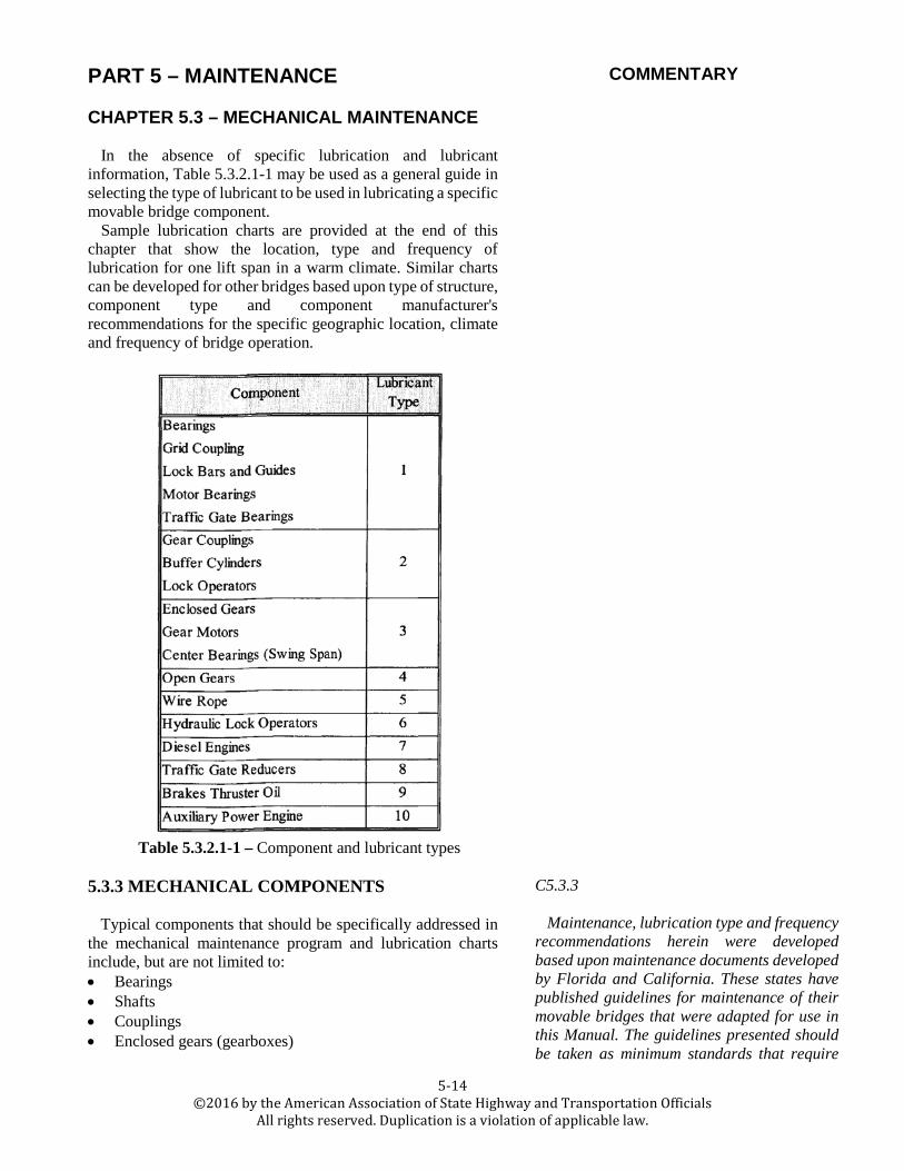
In the absence of specific lubrication and lubricant information, Table 5.3.2.1-1 may be used as a general guide in selecting the type of lubricant to be used in lubricating a specific movable bridge component.
Sample lubrication charts are provided at the end of this chapter that show the location, type and frequency of lubrication for one lift span in a warm climate. Similar charts can be developed for other bridges based upon type of structure, component type and component manufacturer's recommendations for the specific geographic location, climate and frequency of bridge operation.
Table 5.3.2.1-1 – Component and lubricant types
5.3.3 MECHANICAL COMPONENTS
Typical components that should be specifically addressed in
the mechanical maintenance program and lubrication charts include, but are not limited to: • Bearings • Shafts • Couplings • Enclosed gears (gearboxes)
C5.3.3
Maintenance, lubrication type and frequency recommendations herein were developed based upon maintenance documents developed by Florida and California. These states have published guidelines for maintenance of their movable bridges that were adapted for use in this Manual. The guidelines presented should be taken as minimum standards that require

PART 5 – MAINTENANCE COMMENTARY
5-15 ©2016 by the American Association of State Highway and Transportation Officials
All rights reserved. Duplication is a violation of applicable law.
CHAPTER 5.3 – MECHANICAL MAINTENANCE
• Open gears • Brakes • Buffer cylinders • Auxiliary power (engine-generator, gasoline, LPG, or
diesel driven) • Live load shoes and strike plates • Fasteners • Sump pumps • End jacks, center wedges, span locks and other special
machinery • Wire ropes • Balance wheels • Support rollers
modification and application of local knowledge, engineering judgment and sound QC/QA procedures in order to develop reliable lubrication and maintenance practices on an individual movable bridge.
5.3.4 BEARINGS
Bearings are machinery components that provide a low friction interface between rotating and non-rotating parts. Bearings support applied loads, maintain alignment of the members, and minimize frictional power losses. Two primary types of bearings are used on movable bridges: sleeve bearings and anti-friction (ball or roller) bearings. These bearings may be mounted in a variety of housings, the most common types being the pillow-block or flange housings.
One other type of bearing, common only to center bearing swing bridges, is the spherical bronze and hardened steel center bearing.
One factor common to all bearings is the need for a constant supply of lubricant.
Maintenance: The following items should be checked as required (but not less than once every six months): • Check bearing sleeves for lubrication, cracks, scoring, or
severe wear. • Clean and spot paint exterior surfaces as required. • Check condition of the cap and mounting bolts, and tighten
if required. • Make sure lubrication fittings are not plugged and are
operating properly. If necessary, flush with kerosene or other approved solvent. Do not use gasoline or other volatile solvents. When bearings or other components are cleaned internally or flushed with a solvent, it should be noted in the lubrication log.
• If serviced by an automatic lubrication system, check the lubricant level and verify that fresh lubricant is present in all bearings. If no automatic system is present, the bearing should be greased with a hand held gun and the grease applied until a fresh bead of grease appears around the end of the bearing or seal. Wipe off any excess. Check extruded

PART 5 – MAINTENANCE COMMENTARY
5-16 ©2016 by the American Association of State Highway and Transportation Officials
All rights reserved. Duplication is a violation of applicable law.
CHAPTER 5.3 – MECHANICAL MAINTENANCE
grease for contamination visually and by rubbing a small amount between clean fingers to feel for particulate grit. Results should be noted in the lubrication log.
• The frequency of lubrication for sleeve bearings should be based on the openings/month (O/M) of the bridge, as given in Table 5.3.4-1.
Table 5.3.4-1 – Lubrication frequency for bearings
Note: If the center bearing of a swing-span is not lubricated
by means of an immersed oil bath, it is strongly recommended that this type of system be installed as soon as possible. 5.3.5 SHAFTS
Little maintenance is required of shafts except to protect them
from corrosion. A visual inspection for cracks and other defects should be part of a preventive maintenance program. Cracks are the main cause of shaft failures. Cracks usually begin at a point of high stress concentration, such as a keyway or shoulder (a point where the shaft changes diameter). Often a keyway ends at a shoulder producing an especially high stress. Areas subject to heavy corrosion and points having flaws can also cause shaft failures. A preventive maintenance program should include visually inspecting all shafts for cracking and loose keys or set screws.
5.3.6 COUPLINGS Couplings prevent stress buildup in the shafts and bearings
resulting from misalignment. Flexible couplings compensate for parallel misalignment, angular misalignment, or a combination of both. The most common types of couplings used in movable bridges are: gear, chain, grid, and jaw couplings as described in Chapter 2.8.2. Some of the most common causes for flexible coupling failure are extreme misalignment, torque overload, improper type of coupling for the application, and lack of lubrication.
When lubricating the machinery, inspect the couplings for lubrication leaks. If a leak is present and the amount of lubricant escaping is significant, the seals and/or gasket may be defective. Disassemble the coupling, clean with lubricating solvent, and replace the defective components. Lubricate with fresh Type 1 or Type 2 lubricant.

PART 5 – MAINTENANCE COMMENTARY
5-17 ©2016 by the American Association of State Highway and Transportation Officials
All rights reserved. Duplication is a violation of applicable law.
CHAPTER 5.3 – MECHANICAL MAINTENANCE
Maintenance: The following items should be checked as required (but not less than once every six months) when lubricating the coupling: • Check flange bolts for tightness. • Inspect the keys and keyways for signs of cracking. • Inspect the seals and gaskets, replace if leaks are excessive. • Clean any excess grease. As required (but not less than once every two years): • Remove the coupling covers. Check lubricant for
contamination or metal particles. • Clean off old lubricant with lubricating solvent. • Visually inspect mating parts, replace if worn. • Furnish new gaskets and reassemble the covers. • Lubricate with fresh grease as per the manufacturer's
recommendations. • Clean gear teeth when necessary.
5.3.7 ENCLOSED GEARS
Enclosed gears, also called speed reducers or gearboxes, are
used to multiply the output torque and reduce the output speed of the main drive motors.
Speed reducers are gear sets that are mounted in dust proof, oil tight housings. The sealed housings minimize wear from environmental conditions and provide rigid mountings for shaft bearings. Maintenance: • Check seals for signs of leakage and discoloration within
the housing. A small amount of oil seepage during operation is desirable to lubricate the shaft seals. If a severe leak is present, replace the seal. On units with stuffing boxes, tighten the two gland bolts, evenly, just to stop the leak. Do not tighten these glands more than necessary! Over tightening of bolts will create increased friction causing premature failure of the seal and possible scoring of the shaft journal.
• Make sure the vent breather is operating properly. Clean filter material as required.
• Check oil level. Add oil if required. Do not overfill! When adding oil make sure it is of the same type and grade as in the reducer. Mixing of different oils is not recommended. Fill to the center of the oil level indicator. Do not allow the oil level to fall more than ¼ in. (6.4 mm) below the center of the oil level indicator for adequate lubrication.
• Clean the oil level indicator. Note: A speed reducer should never be operated without an oil level indicator installed!
• Look for cracks on the feet of the housing. • Watch the reducer feet during operation. If the mounting
C5.3.7 Different manufacturers may use different
additives in lubricants. If the lubricant manufacturer is changed, the maintainer should be sure that the new lubricant is compatible with the existing. If compatibility between lubricants cannot be verified, drain, flush, and replace the existing lubricant entirely with the new.

PART 5 – MAINTENANCE COMMENTARY
5-18 ©2016 by the American Association of State Highway and Transportation Officials
All rights reserved. Duplication is a violation of applicable law.
CHAPTER 5.3 – MECHANICAL MAINTENANCE
bolts are loose, a small amount of movement may be detectable during operation, especially during starting and stopping. Tighten any loose bolts.
• Check casing bolts for rust and tightness. Torque any loose bolts to the manufacturer's recommended torque. Do not over tighten! Gasket failure may result.
• Watch the shaft extensions during operation for radial or axial movement. Excessive movement indicates worn bearings. Report to the proper authorities for corrective action.
• Listen for any unusual noises. As required, check and correct the following items: • Clean casing. Spot paint as required. • If oil looks dirty or milky white, change the oil. Clean any
sludge or other contaminants from inside surfaces of the case before adding new oil. Make sure no moisture enters the speed reducer during oil change.
• While the sump is drained, remove the inspection cover and visually inspect the interior components. Be extra careful not to allow any contaminants to get inside the sump. Replace the gasket.
• While the inspection cover is removed, flush the interior of the speed reducer with clean lubricating solvent. Drain completely. This will remove any moisture present inside the reducer. It will also remove all old lubrication.
• Overhaul the speed reducers (seals and bearings) as required.
• Change the oil every five years. 5.3.8 OPEN GEARS
Open gears (speed reducers) are often subject to abnormal wear
and corrosion because of unprotected exposure to water, dirt, debris, and the elements. The gears are subject to misalignment caused by the wear of supporting bearings due to the same effects of abnormal wear caused by water and dirt. The maintenance of open gears, pinions, and racks is time consuming and difficult, but is vitally important in extending the life of these parts.
Maintenance: Prior to re-lubricating open gears, it is very important that the gears be cleaned thoroughly. This cleaning can be accomplished by wiping with a rag for some lubricant types or by using an approved solvent. While the gears are clean, prior to applying new grease, the gears should be inspected for any signs of extreme wear, corrosion, or misalignment. After the application of new grease, an inspection should be made of the gears subsequent to the operation of the movable span. This inspection should not only check for the proper application of new grease, but should also
C5.3.8 If the open gearing is exposed to roadway
runoff and debris, consideration should be given to installation of protective covers, enclosures or other measures to protect the gears. Lubricant wiping from the teeth during operation, immediately after application, is an indication that heavier lubrication is needed, that gear bearing pressures are excessive, or both.
PART 5 – MAINTENANCE COMMENTARY
5-19 ©2016 by the American Association of State Highway and Transportation Officials
All rights reserved. Duplication is a violation of applicable law.
CHAPTER 5.3 – MECHANICAL MAINTENANCE
check for the proper meshing of the gears. Any indication that the gears are not showing a uniform pattern of pressure along the pitch lines indicates improper alignment and should be corrected. 5.3.9 BRAKES
Span brakes are used to prevent the bridge from closing when
in the open position, and also prevent opening when in the closed position until the span locks are driven. Brakes also act as a safety device intended to hold the span during an emergency such as motor failure. Motor brakes usually are designed to hold the span during temporary stops by the operator. See Chapter 2.8.2 for component details of different brake types.
Maintenance: As required (but not less than once per year)
check and correct: • Thruster oil level (change if dirty): Use Type 10 aviation
hydraulic oil unless otherwise directed by the bridge maintenance manual or brake manufacturer.
• Tighten loose bolts and replace broken bolts. • Adjust push rod seals (repack if necessary). • Spring adjustment. • Adjust shoe clearance if necessary. • Thruster travel and time for brake to fully engage: Adjust
thruster orifice or travel as required. • Condition of the shoes: Clean and polish any rust on brake
drum and disc. Replace if worn. • Spot paint as required.
When required, completely overhaul the brake unit to include
new seals, shoes, oil, and paint. Maintenance for Solenoid and Magnetic Clapper Brakes:
As required, (but not less than once per year), the following items should be checked and deficiencies corrected: • Collections of dirt, gum or grease: Clean out by using a
small clean paint brush, vacuum cleaner or clean, lint free rags.
• Excessive heating of parts, evidenced by the discoloration of the metal parts, charred insulation, odor or blistering: Replace any burnt parts, solenoid or magnets.
• Freedom of moving parts (no binding or sticking): Operate manually (make sure that power is turned off). Clean moving parts as required. Do not lubricate the unit unless required by the manufacturer.

PART 5 – MAINTENANCE COMMENTARY
5-20 ©2016 by the American Association of State Highway and Transportation Officials
All rights reserved. Duplication is a violation of applicable law.
CHAPTER 5.3 – MECHANICAL MAINTENANCE
• Corrosion of metal parts: Replace any badly corroded parts.
• Loose fasteners: Tighten loose mountings and connections.
• Worn or broken mechanical parts: Replace as required. • Voltage to the solenoid coil or clapper magnets: Correct
the source of over/under voltage. The coil should be replaced if it shows signs of damage.
• Lubrication: Moving parts should be lightly oiled with light machine oil (apply drops with a toothpick to the bearing surfaces). Do not spray the light machine oil.
5.3.10 BUFFER CYLINDERS
Buffer cylinders are used to absorb shock during the closing
of the bridge. Buffer cylinders are mounted vertically on the span on bascule and vertical lift bridges and horizontally on the rest piers on swing span bridges.
Maintenance: As required, but not less than once every six
(6) months, check the following and correct deficiencies as necessary: • Smooth movement of the piston rod. • Adjust the piston rod contact with the strike plate. • Check the piston rod for scoring, rust, and lubrication. • Check for air leaks. • Check pressure gauge (should read between 25–35 psi
(170–245 kPa)). • Replace pressure gages if not working properly. • Replace air valves if not working properly.
Buffer cylinders should be replaced in groups. All cylinders
that are required to perform simultaneously should be replaced as a set.
5.3.11 AUXILIARY POWER Most movable bridges are designed with an auxiliary power
plant to provide power to the bridge in case of failure of the primary power. Auxiliary power usually consists of an internal combustion engine, electric generator, and auxiliary equipment. The engine can be powered by either diesel fuel, gas (natural or LPG), or gasoline. Diesel fuel is preferred. Gas or gasoline systems require adequate ventilation to avoid the risk of explosive vapor accumulation.
Maintenance: The maintenance depends upon the prime mover. One item that is common with all of the types of prime movers is the lubrication. The engine generator sets should be

PART 5 – MAINTENANCE COMMENTARY
5-21 ©2016 by the American Association of State Highway and Transportation Officials
All rights reserved. Duplication is a violation of applicable law.
CHAPTER 5.3 – MECHANICAL MAINTENANCE
exercised at least once a month. Preferably, this should be done under load. However, because the operating time of movable bridges is usually of a very short duration, this is not always possible. The engine should be operated for a sufficient time to bring the engine up to operating temperature. The most damage that can be done to an engine is to operate it for a short time and then shut it down. This causes the unburned fuel to wash down the cylinder walls. It also increases the amount of moisture that is drawn into the crankcase that causes added corrosion.
In order to increase the life of the engine, a regular changing of the lubricating oil is necessary. The oil and oil filter should be changed at least every six months. When the oil and oil filter are changed, the maintainers should visually check the engine-generator set for proper water level in the radiator, the air filter for cleanliness and for any signs of excessive leaks in the hoses and around the bearings of the engine and the generator. A visual check of belts, spark plug wires, and other accessories should be made at this time. The type and viscosity of oil should be as recommended by the engine manufacturer. In the absence of any specific recommendation by the engine manufacturer, a multipurpose oil suitable for diesel, gasoline, natural gas, or LPG fueled engines (10W/40 (or similar); API service CD, CC, SF, SE; or SD fully detergent, all-weather oil formulated to retard the formation of sludge, varnish, and carbon deposits) should be used.
Air Motors: During routine maintenance, make the following checks: • Caution: It is inadvisable to run air motors with no load. Do
not run air motors with motor drive shaft disconnected from span drive.
• Verify that the air supply to the motor is at or near 90 psi (618 kPa) and that it contains lubricating oil.
• Check and refill lubricator. • Check and replace or drain filter cartridges. • Operate the system through an entire cycle and verify
proper speed control, pressure and operational characteristics.
5.3.12 LIVE LOAD SHOES AND STRIKE PLATES Live load shoes and strike plates carry the weight of the traffic
passing over the bridge, and, if provided, are generally located on both sides of the leaves or span.
Every time the machinery is lubricated, maintenance inspectors should check for full contact between the live load shoe and the strike plate, and shim the strike plate or live load shoe as required to obtain full contact. Adjustments should be made with no live load on the bridge. No vertical motion,
C5.3.12
The live load shoe adjustment usually has to be coordinated with the span lock adjustment. For most types of span locks, the adjustment of span locks and live load shoes cannot be done independently of one another.

PART 5 – MAINTENANCE COMMENTARY
5-22 ©2016 by the American Association of State Highway and Transportation Officials
All rights reserved. Duplication is a violation of applicable law.
CHAPTER 5.3 – MECHANICAL MAINTENANCE
clicking, banging, or other signs of lack of a full contact should occur with the passage of vehicles. Shims tend to deteriorate rapidly due to corrosive action and the repeated application of loads causing slight relative movement. This movement results in fretting corrosion. Because of this, the shims should be checked on a regular basis and replaced as required. 5.3.13 FASTENERS
Fasteners are used to hold machinery elements and supports
in place. Fasteners come in different forms: anchor bolts, turned bolts, high strength bolts, and rivets.
During every inspection the fasteners should be checked for tightness. Mounting and cap bolts should be checked for all their nuts to be secured by effective locks. They should not be single-nutted. Maintainers should immediately tighten any loose bolts. Bolts can become stretched from overloads, or work loose from traffic vibrations, and replacement may be required.
During each inspection check the fasteners for corrosion. Report any bolt or rivet that has lost cross sectional area.
Pedestals that have foundation bolts embedded in them should be checked for cracking during each maintenance and safety inspection. Severe horizontal forces transmitted through the bolts to the concrete may crack the pedestal. Concrete that is cracked should be repaired as soon as possible.
C5.3.13 See C5.2.6 for a discussion on stocking
fasteners.
5.3.14 SUMP PUMPS Sump pumps are used to dewater counterweight pits. Sump
pumps are small, automatically operated pumps that are fitted with either floats or other types of liquid level controllers to detect the presence of water in the sump, and activate the pump.
Sump pumps that run infrequently generally do not require much maintenance. However, the following items should be checked every time the bridge is lubricated and repaired or corrected as necessary: • Discharge line and fittings for breaks and leaks. • Power lines for shorts and breaks. • Suction screen for breaks or clogging. • Pump operation should be tested by pouring water into the
sump until the pump actuates automatically and monitored until the pump shuts down automatically.
5.3.15 END JACKS, CENTER WEDGES, SPAN LOCKS AND OTHER SPECIAL MACHINERY
There are many types of end jacks, center wedges, span locks,
and other machinery especially designed for certain types of
PART 5 – MAINTENANCE COMMENTARY
5-23 ©2016 by the American Association of State Highway and Transportation Officials
All rights reserved. Duplication is a violation of applicable law.
CHAPTER 5.3 – MECHANICAL MAINTENANCE
movable bridges. These types of machinery are usually comprised of the various components discussed in this chapter and their maintenance and lubrication should be similar to those components. 5.3.16 WIRE ROPES
Wire ropes, found primarily on vertical lift bridges, serve a
dual purpose as suspender ropes and as operating ropes. Wire ropes are formed by spirally winding individual strands of wire into a rope configuration. As they are formed, they are usually wound around a core of jute saturated with lubricant. During this forming process, the strands are also lubricated. The lubricant prevents the individual wires from experiencing internal abrasion wear and/or corrosion and must be replenished in order to extend the life of the wire rope.
Maintenance: Wire ropes used for suspender ropes on vertical lift bridges should, as a general rule, be cleaned and lubricated at least every 2,000 openings or yearly, whichever occurs first. Maintainers should note any worn, broken, misaligned, and corroded strands and file a deficiency report if the number of damaged or broken wires exceeds the guidelines in Section 2.8.2.11.4. Because of the large ratio of sheave diameter to rope diameter, internal friction between individual strands is usually not a concern with suspender ropes. Corrosion of the outer wire layers is the primary problem encountered with suspender ropes.
The type of lubricant for wire ropes depends on many factors such as rope type, the temperature at which the rope is operating, and whether or not the rope is subject to reverse bending. The lubricant must be “thin” enough to provide protection against corrosion of the outer strands.
C5.3.16 The suspender ropes require thorough
cleaning prior to lubrication. Any area that shows signs of requiring spot lubrication can be handled by the everyday maintenance person, but extensive cleaning and lubrication should be handled by personnel with the equipment and knowledge to perform this work. In selecting a lubricant, it is recommended that the services of a qualified rope manufacturer be engaged.
The maintenance interval that is appropriate for wire ropes is significantly affected by environmental conditions, load in the rope, sheave diameter, wire rope type and size, lubrication type and quality of application procedures. Individual owners should modify the suggested intervals based upon performance in actual use at the particular bridge site.
5.3.17 BALANCE WHEELS The balance wheels on center bearing swing spans maintain
span stability in a near horizontal plane when the span is moving to the open position. They are not designed to carry any of the dead load or live load of the span. The wheels, generally made of cast iron, rotate on sleeve bearings. They ride on a circular track that is usually cast integrally with the operating rack. The wheels are set with a very small clearance between the wheel and the track. Maintainers should verify the required clearance between the wheels and track, and report any change in alignment.
Except for periodic lubrication of the bearings, and an occasional painting, the balance wheels require little maintenance. The bearings of the balance wheels should be

PART 5 – MAINTENANCE COMMENTARY
5-24 ©2016 by the American Association of State Highway and Transportation Officials
All rights reserved. Duplication is a violation of applicable law.
CHAPTER 5.3 – MECHANICAL MAINTENANCE
lubricated in accordance with Table 5.3.2.1-1. The outer surface of the wheel and the treads may be coated with dry lubricant, or wiped with a rag saturated in a light weight (number 10) oil, and then wiped nearly dry to prevent corrosion. 5.3.18 SUPPORT ROLLERS
The support rollers for rim bearing swing spans carry the
entire dead and live load of the span. The rollers are tapered and held in proper radial alignment by structural members or rods that are, in turn, held in place by a center casting, which rotates about a center pivot pin. The support rollers are usually made of cast steel, and are fitted with bronze bearings. Since the rollers are tapered, it is necessary to maintain their radial position with thrust bearings.
The primary maintenance required for support rollers is lubrication. Because of the heavy loads imposed on the rollers, it is impossible to maintain the paint on the surface of the support rollers and treads. Therefore, a frequent light coating of 10 weight oil on the surface that is then wiped almost dry to reduce adhesion of grit is a typical method to reduce corrosion. Special attention should be given to verify that the thrust bearings are receiving sufficient lubrication. The thrust bearings, center pivot bearing, and wheel bearings should be greased in accordance with Table 5.3.2.1-1.
5.3.19 MAINTENANCE LUBRICATION LOG In order to evaluate the effectiveness of existing methods, and
facilitate QC/QA measures for maintenance of mechanical components, it is often useful to have records of how often lubrication is performed, by whom, the type of lubricant used, comments on any problems or observations and listing of any corrective measures. If a bearing grease fitting or grease passageway has experienced caking of lubricant and has been flushed out with solvents such as kerosene, it is important to have this information available for evaluators when corrective measures are being developed. A sample lubrication log is shown in Table 5.3.19-1.
C5.3.19
The lubrication log is used to record lubrication data from the field for QC/QA purposes and to verify that recommended lubrication has been performed, and by whom.
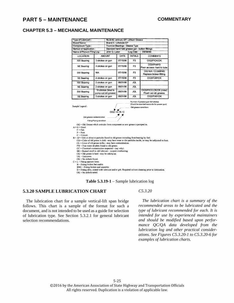
PART 5 – MAINTENANCE COMMENTARY
5-25 ©2016 by the American Association of State Highway and Transportation Officials
All rights reserved. Duplication is a violation of applicable law.
CHAPTER 5.3 – MECHANICAL MAINTENANCE
Table 5.3.19-1 – Sample lubrication log 5.3.20 SAMPLE LUBRICATION CHART
The lubrication chart for a sample vertical-lift span bridge
follows. This chart is a sample of the format for such a document, and is not intended to be used as a guide for selection of lubrication type. See Section 5.3.2.1 for general lubricant selection recommendations.
C5.3.20 The lubrication chart is a summary of the
recommended areas to be lubricated and the type of lubricant recommended for each. It is intended for use by experienced maintainers and should be modified based upon perfor-mance QC/QA data developed from the lubrication log and other practical consider-ations. See Figures C5.3.20-1 to C5.3.20-6 for examples of lubrication charts.

PART 5 – MAINTENANCE COMMENTARY
5-26 ©2016 by the American Association of State Highway and Transportation Officials
All rights reserved. Duplication is a violation of applicable law.
CHAPTER 5.3 – MECHANICAL MAINTENANCE
Figure C5.3.20-1 – Lift bridge lubrication chart

PART 5 – MAINTENANCE COMMENTARY
5-27 ©2016 by the American Association of State Highway and Transportation Officials
All rights reserved. Duplication is a violation of applicable law.
CHAPTER 5.3 – MECHANICAL MAINTENANCE
Figure C5.3.20-2 – Typical lubrication schedule

PART 5 – MAINTENANCE COMMENTARY
5-28 ©2016 by the American Association of State Highway and Transportation Officials
All rights reserved. Duplication is a violation of applicable law.
CHAPTER 5.3 – MECHANICAL MAINTENANCE
Figure C5.3.20-3 – Machinery lubrication items

PART 5 – MAINTENANCE COMMENTARY
5-29 ©2016 by the American Association of State Highway and Transportation Officials
All rights reserved. Duplication is a violation of applicable law.
CHAPTER 5.3 – MECHANICAL MAINTENANCE
Figure C5.3.20-4 – Machinery lubrication items

PART 5 – MAINTENANCE COMMENTARY
5-30 ©2016 by the American Association of State Highway and Transportation Officials
All rights reserved. Duplication is a violation of applicable law.
CHAPTER 5.3 – MECHANICAL MAINTENANCE
Figure C5.3.20-5 – Machinery lubrication items
5.3.21 OPERATOR’S (TENDER’S) HOUSE The operator’s (tender’s) house mechanical systems should
be regularly maintained to provide a safe and comfortable environment for the bridge tender. Regular maintenance should include the following items: • Test smoke alarm system for proper function and inspect
fire extinguishers for proper charge. • Check plumbing, piping, and heating systems for leaking or
loose joints. • Replace heating and air conditioning system filters and
perform manufacturer recommended routine HVAC maintenance as required.

PART 5 – MAINTENANCE COMMENTARY
5-31 ©2016 by the American Association of State Highway and Transportation Officials
All rights reserved. Duplication is a violation of applicable law.
CHAPTER 5.4 – HYDRAULIC MAINTENANCE
5.4.1 GENERAL Hydraulic systems that are not properly maintained are prone
to leak, may blow a seal or fail to operate at any time, particularly during adverse weather conditions when operating loads from wind or ice increase the loads in the system.
Leakage and improper performance are unacceptable eventualities that can only be avoided by diligent maintenance, inspection, testing, cleaning, adjustment and repair.
Inspection for maintenance is similar to safety inspection, but may involve considerably more disassembly. See Section 2.8.2.12 for basic inspection recommendations. Detailed procedures involving disassembly are covered in this chapter.
C5.4.1 This Manual is not intended to cover detailed
individual inspection, testing, adjustment, and repair procedures for specific manufactured components. The operation and maintenance manuals should cover these items, if bridge-specific manuals are available for the structure. If manuals are not available, maintainers should obtain the necessary documentation from the manufacturer of the individual components. Most hydraulic components have unique proprietary design features that must be explained by the original component manufacturer, if proper maintenance is to be performed.
5.4.2 HYDRAULIC COMPONENTS Typical hydraulic components that should be specifically
addressed in the hydraulic maintenance program include, but are not limited to the following: • Accumulators • Valves • Hydraulic cylinders • Hydraulic pumps • Hydraulic motors and rotary actuators • Filters • Rigid piping and tubing • Hydraulic hose • Reservoirs • Radiators or other system cooling devices • Hydraulic fluids • Hydraulic system interlocking sensors and controls • Hydraulic system checkout
C5.4.2 Unique designs and unusual systems, which
are beyond the scope of this Manual, may be present on some existing bridges. Maintainers responsible for such systems should develop a detailed maintenance program that addresses the specific equipment present on the bridge. Assistance may be provided by experienced designers, manufacturers, and maintainers of hydraulic systems. Because specific details of individual components vary from manufacturer to manufacturer, specification information should be obtained from the manufacturer.
5.4.3 ACCUMULATORS Accumulators should be performance tested by observing the
pump cycle timing during each maintenance inspection. If pump cycle timing varies from one inspection to the next, the loss of gas cushion from within the accumulators may be the reason. The smaller the gas cushion within the accumulators, the shorter the time will be from pump shut-off at the high pressure switch cutoff point to pump restart at the low pressure pump start point. System pressures should also be recorded at pump stop and start to check that the pressure switch has not been reset or damaged. Checks should be made for leaks and/or pump damage that may
C5.4.3 Caution: Accumulators are pressure
vessels. Inspectors should use extreme care during inspection. Only qualified, trained maintainers should disassemble accumulators for inspection.

PART 5 – MAINTENANCE COMMENTARY
5-32 ©2016 by the American Association of State Highway and Transportation Officials
All rights reserved. Duplication is a violation of applicable law.
CHAPTER 5.4 – HYDRAULIC MAINTENANCE
cause rapid pump cycling. Bladder-type accumulators present on newer systems rarely have this problem. The older piston type or other accumulators may be sounded with a hammer handle or mallet to determine fluid level. This level should be marked on the tank exterior for monitoring.
A reliable method to verify a failed bladder type accumulator is to bleed hydraulic pressure and check the remaining gas pre-charge pressure against the original pre-charge pressure. Pre-charge pressure should be checked and adjusted periodically. 5.4.4 VALVES
A checklist for recurrent solenoid burnout of AC valves is pre-
sented in this section. Coil burnout is more common on AC than on DC valves because of the high inrush current. Until the arma-ture can pull in and close the air gap in the magnetic loop, the inrush current is often five times as high as the steady state, or holding current after the armature has seated. Inrush is approximately the same as holding current on a DC valve.
Coil does not match operating voltage: Improper match between the electrical source and the coil solenoid is sometimes a cause for coil burnout. Check these possible causes: • Voltage too high: The operating voltage should not be
more than 10 percent higher than the coil voltage rating. Excessive voltage causes excessive coil current, which may overheat the coil.
• Voltage too low: The operating voltage should be no less than 10 percent below the coil voltage rating. Low voltage reduces the mechanical force of the solenoid. It may not be able to overcome the spring pressure and continue to draw inrush current, and be unable to actuate the valve.
The low voltage test should be made by measuring the voltage
directly on the coil wires while the solenoid is energized, and with its armature blocked open so it is drawing in rush current. Energize the solenoid just long enough to take a voltage reading. Also take a no-load reading with the solenoid coil disconnected from the feed wires. A difference of no more than 5 percent between these two readings indicates excessive resistance in the wiring circuit or insufficient volt-ampere capacity in the control transformer.
Overlap in energization: On some double solenoid valves, if both solenoids are energized at the same time and held in this state for a short time, the last coil to be energized will burn out from the excessive inrush current.
This burnout condition will occur only on double solenoid valves where the two solenoids are yoked to opposite ends of a common spool. If each solenoid is free to immediately close its
C5.4.4 Valve inspection is covered in Section 2.8.2.
Normal valve maintenance should not require disassembly. However, as valve seals and springs age, pressure and flow control valves require adjustment to maintain design system pressures. Performance tests of valves can be done using manufacturers' recommended procedures and the manual override features built into some remote valves to facilitate diagnostic tests. Disassembly for replacement of seals and other internal parts should only be done by trained specialists, who have been given appropriate instruction by the valve manufacturer, or other parties with pertinent knowledge about the individual valve model being serviced.

PART 5 – MAINTENANCE COMMENTARY
5-33 ©2016 by the American Association of State Highway and Transportation Officials
All rights reserved. Duplication is a violation of applicable law.
CHAPTER 5.4 – HYDRAULIC MAINTENANCE
air gap, neither will bum out if both are simultaneously energized.
Careful attention must be given to electrical circuit wiring to make certain that the system does not energize both solenoids at the same time.
Even with correct circuit design and interlocking circuits, a relay with sticking contacts, or slow release, could be responsible for a momentary overlap of energization on each cycle and eventual premature coil burnout.
Rapid cycling: Since inrush current is much more than holding current, a standard AC coil on an air gap solenoid may overheat and burn out if required to cycle too frequently. The extra heat generated during inrush periods cannot dissipate fast enough. The gradual buildup of heat inside the coil winding may, in time, damage the coil insulation.
High cycling applications can be roughly defined as those requiring the solenoid to be energized more than 5 times per minute. On these applications, oil immersed solenoids are required. The coil of this type operates cooler because heat is conducted more rapidly from the winding through the oil.
Dirt in oil or atmosphere: A small solid particle lodged under the solenoid armature may keep it from fully seating against the core, causing coil current to remain higher than normal during the holding period. Be sure that solenoid dust covers remain tightly in place to protect against dust deposited from the air.
Small dirt particles in the oil may lodge on the surface of the valve assembly, glued there by varnish circulating in the oil, or the varnish itself may cause excessive spool drag and excessive coil current. Varnish often forms in systems where the oil is allowed to run too hot.
Environmental conditions: Abnormally high or low ambient temperatures to which a solenoid is exposed for an extended period of time may cause the coil to burn out. • High temperature: Coil insulation may be damaged and
one layer of wire may short to the next layer. A heat shield between the valve and the heat source may give some protection against radiated heat. Oil immersed solenoids afford the best protection against heat conducted either through metal surfaces or from surrounding high temperature.
• Low temperature: Cold ambient temperatures cause hydraulic fluid to become more viscous, possibly overloading the solenoid valve capacity. Mechanical parts of the valve or solenoid structure may distort, causing the valve spool to stick and burn out the coil. Hydraulic systems in cold climates should be designed to keep fluid temperature within the acceptable range for the fluid and all

PART 5 – MAINTENANCE COMMENTARY
5-34 ©2016 by the American Association of State Highway and Transportation Officials
All rights reserved. Duplication is a violation of applicable law.
CHAPTER 5.4 – HYDRAULIC MAINTENANCE
components. If high viscosity during cold weather is believed to be a cause for component failure, the system should be heated to control hydraulic fluid temperatures within the acceptable range.
Dead end service: Fluid circulating through a solenoid valve helps carry away electrical heat. Some valves depend on fluid flow to keep excessive heat from accumulating, and if used on dead end service, where the solenoid may remain energized for a long time without any fluid flow, the coil may be prone to burn out.
Atmospheric moisture: High humidity, along with frequently changing ambient temperature, may form corrosion due to condensation on metal parts of the solenoid structure, causing the armature to drag or the spool to stick. Humidity also tends to deteriorate standard solenoid coils, causing shorts in the windings.
Changing to molded coils or oil immersed solenoids may correct this type of problem. Keep solenoid protective covers tightly in place, and it may be advisable to seal the electrical conduit openings after the wiring is installed.
5.4.5 HYDRAULIC CYLINDERS
Figure 5.4.5-1 shows an exploded view of a typical double
acting hydraulic cylinder. The key to maintenance of hydraulic cylinders is to keep them and the fluid clean. Cylinders are precision machined and polished both internally and on the piston shaft so that seals seat positively without leakage, and also to prolong seal life. Nothing will lead to faster development of leaks than the intrusion of abrasive grit in the hydraulic fluid, or grit adhered to the piston shaft building up and bypassing the wiper seal. The environment at most movable bridges is hostile and prone to intrusion of gritty particulates that are wet and salt contaminated. Every effort should be made by maintenance forces to control the inflow of this hazardous material to the area of all hydraulic components, but particularly to the area where hydraulic cylinders are present. Hydraulic cylinders should be kept clean and completely free of grit and contaminants that might adhere to the piston shaft.
C5.4.5 Cylinder inspection is covered in Chapter
2.8.2. The discussion about valve disassembly for part replacement presented in C5.4.4 applies to cylinders, pumps, motors and other manufactured components.

PART 5 – MAINTENANCE COMMENTARY
5-35 ©2016 by the American Association of State Highway and Transportation Officials
All rights reserved. Duplication is a violation of applicable law.
CHAPTER 5.4 – HYDRAULIC MAINTENANCE
Figure 5.4.5-1 – Typical double-acting cylinder
The following additional items should be checked periodically by maintenance forces: • Cylinder end fittings and mounts should be checked for
cleanliness and for wear. Alignment of the cylinders and attachments should be checked at the same time. Misaligned cylinders wear very quickly and will soon begin to leak due to rapid seal wear.
• Gland end caps should be checked for leakage. A primary area of concern is that the cylinder is never disassembled without careful cleaning. It is imperative that any contaminants be thoroughly cleaned off the exterior before the cylinder is disassembled. Internal parts should be cleaned carefully with a lint-free cloth before reassembly.
• Wiper seal and housing should be examined for surface deterioration and/or signs that grit has passed through and adhered to the piston shaft.
• Maintainers should examine the fully extended piston shafts during every maintenance inspection. The shaft should have a mirror polished surface without any scratches, striations, or scoring. If scoring is found, every effort should be made to immediately determine and correct the cause. Damaged piston shafts or internal surfaces of the cylinder will wear seals rapidly. Damaged surfaces may be refinished, but this is expensive and requires component removal and a significant amount of downtime, unless spares are installed in the interim.

PART 5 – MAINTENANCE COMMENTARY
5-36 ©2016 by the American Association of State Highway and Transportation Officials
All rights reserved. Duplication is a violation of applicable law.
5.4.6 HYDRAULIC PUMPS The pump is the component most subject to wear and the one
most likely to give trouble. On systems where the pump has to be replaced more often than seems necessary, one or more of the following problems may be the cause:
Pump cavitation or air leaks: Cavitation or fluid aeration by air leakage cause an inability of the pump to draw a full charge of hydraulic fluid. When a pump starts cavitation, its noise level increases and it may become very hot around the shaft and front bearing. Cavitation is a process in which tiny gas or vapor bubbles implode at the pump outlet, causing metal erosion, leading ultimately to pump destruction. The inspector will probably be able to hear a buzzing, rattling sound in the pump if there is cavitation. The sound is as though a handful of stones were tossed into the pump. A worn pump may also cause noise (see Table 2.7.7-1 for additional details). Other symptoms of cavitation or aeration are erratic movement of the cylinders, difficulty in building up full pressure, and a milky appearance of the hydraulic fluid. If cavitation is suspected, check these points: • Check the condition of the pump inlet strainer. Clean it even
if it does not look dirty. Use a solvent and blow dry with an air hose using only dry, clean air. Varnish deposited in the wire mesh could be restricting the hydraulic fluid flow even though it may be almost invisible. If brown varnish deposits are found on the internal surfaces of the pumps or valves, this is a sure indication that the system has been operating at too high a temperature. A heat exchanger, or other system designed to reduce maximum operating temperature to within the acceptable range for the fluid should be installed.
• Check for restricted or clogged pump inlet plumbing. If hoses are used on the inlet side, be sure they are not collapsed. Only hoses designed for vacuum service should be used at the pump inlet. They have an internal wire braid or other special design features to prevent collapse.
• Be sure the air breather on the reservoir is not clogged with dirt or lint. On systems where the air space above the hydraulic fluid is relatively small, the pump could cavitate during its extension stroke if the breather becomes clogged.
• Hydraulic fluid viscosity may be too high for the particular pump. Some pumps cannot pick up prime on heavy hydraulic fluid or will run in a cavitated condition.
• Cold weather start-up can be particularly damaging to a pump. Running a pump across a relief valve for several hours to warm up the hydraulic fluid can severely damage the pump if it is running in a cavitated condition during this time.
• Check the pump inlet strainer size. Be sure the original strainer has not been replaced with a smaller size.

PART 5 – MAINTENANCE COMMENTARY
5-37 ©2016 by the American Association of State Highway and Transportation Officials
All rights reserved. Duplication is a violation of applicable law.
CHAPTER 5.4 – HYDRAULIC MAINTENANCE
Increasing its size (number of square inches of filtering surface) may help.
• The use of a higher quality hydraulic fluid may reduce the formation of varnish and sludge.
• Determine the recommended speed of the pump. Make sure the original electric motor has not been replaced with one that runs at a higher speed.
• Be sure the pump has not been replaced with one that delivers a higher flow rate that overloads the inlet strainer. Increase the inlet size if possible.
Air Leaking into the System: The air that is in a newly
assembled system should purge itself after a short time. The system should be run perhaps 15 to 30 minutes under very low pressure. Air will dissolve in the hydraulic fluid, a little at a time, and be carried to the reservoir from where it can escape. The air purging process should be accelerated by bleeding air from high points in the system, especially on the cylinders.
Air, which comes into the system from continuous air leaks, will cause the hydraulic fluid to assume a milky appearance a short time after the system is started. To find where air is entering the system, check the following: • Be sure the hydraulic fluid reservoir is filled to its normal
level, and that the pump intake is well below the minimum hydraulic fluid level. The NFIPA reservoir specifications call for the highest point on the strainer to be at least 3.0 in. (76 mm) below minimum hydraulic fluid level. Check the hydraulic fluid level when all cylinders are extended to be sure it is not below the “low” mark on the level gauge. However, do not overfill the reservoir when the cylinders are extended; it may overflow when the cylinders retract.
• Air may be entering around the pump shaft seal. Gear and vane pumps, which are pulling hydraulic fluid by suction from a reservoir, will have a slight vacuum behind the shaft seal. When this seal becomes badly worn, air may enter through the worn seal. Piston pumps usually have a small positive pressure, up to 15 psi (103 kPa), inside the case and behind the shaft seal. Air is unlikely to enter through this route.
• Check for air leaks in the pump inlet plumbing, especially at union joints. Check for leaks in hoses used at the inlet line. An easy way to check for leaks is to squirt hydraulic fluid over a suspected leak. If the pump noise diminishes after you seal around a fitting temporarily with fluid, you have found a leak. Check also around the inlet port. Screwing a tapered pipe fitting into a straight thread port will damage the thread, causing a permanent air leak, that

PART 5 – MAINTENANCE COMMENTARY
5-38 ©2016 by the American Association of State Highway and Transportation Officials
All rights reserved. Duplication is a violation of applicable law.
CHAPTER 5.4 – HYDRAULIC MAINTENANCE
is difficult to repair. • Air may enter through the rodseal of a cylinder. This can
happen on cylinders mounted with the rod up that are not properly counterbalanced. On the downstroke, the gravity load may cause a partial vacuum in the rod end of the cylinder. Cylinder rod seals are not designed to seal air out.
• Be sure the main tank return line discharges well below the minimum hydraulic fluid level, and not on top of the hydraulic fluid. On new designs, it may be helpful to enlarge the diameter of the main return line a few feet before it enters the tank. This causes the hydraulic fluid velocity to decrease, which minimizes turbulence in the tank.
Hydraulic fluid leakage from the pump: In case of hydraulic fluid leaking from the pump, maintainers should consider the following procedures: • Leakage around the shaft: On piston pumps and on other
pumps that take the inlet hydraulic fluid from an overhead reservoir, there is usually a slight internal pressure behind the shaft seal. As the seal becomes worn, external leakage may appear. This will usually be more pronounced while the pump is running, and may disappear while the pump is stopped. Leakage is unacceptable and should be corrected by installing new seals. Other pumps, such as gear and vane types, usually run with a slight vacuum behind the seal. A worn-out seal may allow air to leak into the hydraulic fluid while the pump is running, and hydraulic fluid to leak out after the pump has been stopped. Both conditions are unacceptable and new seals should be installed.
• Prematurely worn shaft seals may be caused by excessive hydraulic fluid temperature. At hydraulic fluid temperatures of 200°F (93°C) and higher, a rubber shaft seal will have a very short life. Few seals are designed to operate above 200°F (93°C). Abrasives in the hydraulic fluid may wear out shaft seals quickly, and may also produce circumferential scoring on the shaft. If abrasives are present, they will settle out of a hydraulic fluid sample drawn from the reservoir after the sample has been allowed to stand for an hour. Check all crevices and cracks in the reservoir where dust could enter. The most common entry point is through the reservoir air breather. In extreme cases, the reservoir may have to be sealed air tight, and a slight air pressure of no more than 1.0 psi (7.0 kPa) maintained in the reservoir air space.
• Leakage around a pump port: Sometimes leakage at these ports may be caused by damaged threads. Once threads have been damaged, it is very difficult to obtain a

PART 5 – MAINTENANCE COMMENTARY
5-39 ©2016 by the American Association of State Highway and Transportation Officials
All rights reserved. Duplication is a violation of applicable law.
CHAPTER 5.4 – HYDRAULIC MAINTENANCE
leak tight seal. The pump may require replacement if leakage is chronic. Check the tightness of fittings in the ports. If dry seal (National Pipe Taper Fuel or NPTF) pipe threads are used, there should seldom be a need for any kind of thread sealant. If a sealant is used, teflon sealant that comes in the form of a paste is preferred. Do not use teflon tape, which can foul valves, if it enters the system. Beware of screwing tapered pipe threads too tightly into a pump or valve body casting. In the past, this has been the cause for many cracked pump housings.
• If the leakage is from a small crack in the body casting, this has most likely been caused by over tightening a tapered pipe fitting, or from operating the pump in a system where high pressure spikes have been generated as a result of shocks.
Pump delivering little or no flow: In case of pump delivering little or no flow, maintainers should consider the following procedures: • The shaft may be rotating in the wrong direction. Shut
down immediately. Reversed leads in a three-phase electric motor are a common cause for wrong rotation. Pumps must be run in the direction marked on their nameplate or case.
• The pump inlet may be clogged or restricted. Check the strainer for dirt, and check for a collapsed inlet line.
• Hydraulic fluid may be low in the reservoir. Check the level when all the cylinders are extended.
• Stuck vanes, valves or pistons, may occur either from varnish or water in the hydraulic fluid causing corrosion. Varnish indicates the system is running too hot.
• The hydraulic fluid may be too thin, either from the wrong choice of hydraulic fluid, or from its thinning out at high temperature. A system with this problem may operate normally the first few hours after start-up, then gradually slow down as the hydraulic fluid gets overheated and loses viscosity.
• Mechanical trouble: Check for broken shafts or couplings, sheared keys or pins, etc.
• Pump running too slow: Most pumps deliver flow rate proportional to the RPM. Some vane-type pumps depend on centrifugal force to extend the vanes into contact with the cam surface, and will deliver little flow at slow speeds.
• If the driving electric motor has been replaced, make sure it is the correct speed for the pump.
Pump noise has recently increased: In case the pump noise has recently increased, the maintainers should consider the following procedures: • Cavitation of the pump inlet. Refer to the corrective
measures previously described.

PART 5 – MAINTENANCE COMMENTARY
5-40 ©2016 by the American Association of State Highway and Transportation Officials
All rights reserved. Duplication is a violation of applicable law.
CHAPTER 5.4 – HYDRAULIC MAINTENANCE
• Air leaking into the system from low hydraulic fluid or other causes previously described.
• Mechanical noise caused by loose or worn couplings, loose set screws, badly worn internal parts, etc.
• The system may be running with the hydraulic fluid temperature too high.
• The pump may be running at higher than its rated speed. Short pump life: in case the pump requires frequent
replacement, the maintainers should consider the following procedures: • The pump may be operating above rated maximum
pressure. This is a problem, especially if the pump must maintain this pressure for a high percentage of the total running time.
• Hydraulic fluid of incorrect viscosity or of poor quality. • Running the system at excessively high temperatures. • Inadequate filtering: Check hydraulic fluid for
contamination, and add more or better filters if necessary. • Improper maintenance, particularly failure to regularly
clean: Replace the pump inlet strainer, and all filters. • Misalignment of the pump shaft with the motor or the
engine shaft. • The pump may be running too fast (or too slow): Check
RPM. • Inlet cavitation from causes other than listed above. • Air or water leaking into the system. 5.4.7 HYDRAULIC MOTORS AND ROTARY ACTUATORS
These components should be maintained similarly as
previously stated for pumps. Hydraulic motors and actuators are basically hydraulic pumps that are running backward, pressure generates motion instead of the other way around.
5.4.8 FILTERS Systematic filter maintenance, along with fluid replacement,
can eliminate many potential causes of hydraulic system failures. In addition, installation of new filtration techniques, which remove particles down to the 1 micrometer (4.0 × 10⁻⁵
in.) level, can greatly extend the life of system components. Typical newer installations use 10 micrometer (4.0 × 10⁻⁴ in.) filtration, which is adequate in most applications on movable bridges.
Most hydraulic systems continually re-circulate the same hydraulic fluid. Although the systems are “closed” they are not dirt proof. Harmful dirt and foreign particles may be built-in,
C5.4.8 Periodic sampling and testing of hydraulic
fluid can verify filter effectiveness. See Chapter 2.10, Testing and Advanced Inspection Methods.

PART 5 – MAINTENANCE COMMENTARY
5-41 ©2016 by the American Association of State Highway and Transportation Officials
All rights reserved. Duplication is a violation of applicable law.
CHAPTER 5.4 – HYDRAULIC MAINTENANCE
introduced, or produced by wear. Built-in contaminants (or dirt) result largely from the manufacture of the equipment, and include core sand, weld splatter, metal chips, lint, and abrasive dust. Introduced contaminants enter the system through seals, hydraulic fluid filler tubes, and breather caps in reservoirs. Lint and other foreign matter may enter when the system is opened.
The hydraulic fluid used for replenishing might contain dirt. Wear contaminants include small particles of metal and sealing materials that result from the wear of moving parts within the system. Hydraulic fluid breakdown can result in the formation of sludge and acids. Acid results from chemical reactions within the hydraulic fluid caused by water, air, heat and pressure, as well as incompatible hydraulic fluids. Sludge is not generally abrasive. However, it is recognized as the source of resinous and gummy coatings on moving parts, and can clog valves and passages. Acids can pit and corrode critical moving parts.
Pressure drop: All system components through which there is flow have a pressure drop. This drop is the net pressure required for the hydraulic fluid to flow from the inlet to the outlet of the component. In filters, this includes the pressure drop across the housing and the filter element. It varies with the flow rate, hydraulic fluid viscosity, and amount of dirt in the filter.
Dirt capacity: This is the maximum amount of contaminant that can be collected by a barrier type filter element without producing a pressure drop that affects the hydraulic system function or damages the filter element. Initially, pressure drop increases only slightly with increasing contaminant collection.
Filter element maintenance recommendations can be based on either a time interval, or pressure drop readings. Service interval recommendations, based upon hours of operation, should be conservative because many factors, which cannot be accurately predicted, affect the rate of contaminant collection. Alternately, for full flow filters, differential pressure readings indicate the actual amount of contaminant collection, and thus are a more realistic basis for element servicing.
With increased emphasis on prevention of bridge downtime, the need for much higher standards of hydraulic fluid cleanliness is ever present. Since pumps and valves have clearances on the order of 5 micrometer (2.0 × 10⁻⁴ in.), it is easy to understand the need for maintaining contaminant particles below this size. To meet this demand, filters are now available capable of filtering down to the 1 micrometer (4.0 × 10⁻⁵ in.) level for flow rates over 100 GPM (6.31 lit/s) and for systems with 5,000 psi (34.47 MPa) pressure.
Owners experiencing problems with contamination of hydraulic system fluid should consider the use of portable recirculating units, which are capable of reducing the contaminant level of the hydraulic fluid to the 1 micrometer

PART 5 – MAINTENANCE COMMENTARY
5-42 ©2016 by the American Association of State Highway and Transportation Officials
All rights reserved. Duplication is a violation of applicable law.
CHAPTER 5.4 – HYDRAULIC MAINTENANCE
(4.0 × 10⁻⁵ in.) level, and that can rapidly process the oil in the system at one bridge after another. 5.4.9 RIGID PIPING AND TUBING
Maintaining hydraulic fluid conducting pipes, tubing, and
fittings is a high priority aimed at providing maximum uptime and a minimum of hydraulic fluid leaks and downtime.
Beyond system integrity (or leak-proofness) and adequate service life, these components should provide minimal loss of power, and minimal pressure drop, as they convey the hydraulic fluid through the system. This means that the fewer the fittings and couplings, the better, since each contributes to the pressure drop. This requirement also calls for minimizing the number of sharp turns in the hydraulic fluid lines, and maintaining the recommended bend radius of each tube or pipe, whether it is original equipment or a replacement.
For the same reason, tubing and pipes must be sized properly to permit adequate flow without boosting hydraulic fluid velocity above good design practice levels; generally not more than 15 ft./sec (4.5 m/sec) in pressure lines, and not more than 5 ft./sec (1.5 m/sec) in suction lines.
In movable bridge hydraulic systems, a number of different types of lines are used. Thus, the fittings, and other hardware needed to connect them, cover a broad range of types, each with specific advantages, and most with some disadvantages. In making the connections from one line to another through fittings or couplings, it is not acceptable for any amount of hydraulic fluid to leak from the system when the fitting is fully tightened. Flared fittings, tapered pipe thread, and a number of types of fittings currently in service are sometimes leak prone. Where possible, replacement pipe, tubing and fittings should conform to current AASHTO specifications (Reference 7).
Copper and brass pipe or fittings are unacceptable for hydraulic plumbing.
Pipe: Pipe has been used for many years and continues to be popular. The current trend is away from tapered pipe threads to straight threads or flanged ends that seal with an “O” ring. The objection to taper threads is that they often develop leaks that are hard to repair in the field. Components built overseas often have BSP (British Standard Pipe) ports that have a straight thread sealed with soft packing.
To minimize thread leaks, the NPTF (National Pipe Taper Fuel) thread form (also known as Dryseal) was developed to replace the standard NPT (National Pipe Taper) thread form used for so many years. Both of these thread forms are physically interchangeable, but the thread shape of the NPTF is modified to reduce spiral leakage around the crest of the threads. For hydraulic plumbing, the NPTF thread form should
C5.4.9
Flow rates can be verified by various means. The simplest is timed discharge into a container of known volume. This process can be used during fluid changes as a method to rapidly remove a portion of the fluid, and to flush the system, as long as care is exercised to avoid running the reservoir inlet dry. The formula Q = VA, where Q is the flow rate in cubic feet per second (m3/s), V is the velocity in feet per second (m/s), and A is the interior cross sectional area of the discharge line in square feet (m2), can be used to calculate flow velocity. If 13.1 CF (0.371 m3) of fluid discharge from a 2 in. (50.8 mm) ID pipe in one minute, then the flow velocity V = Q/A = 13.1 CFM/.02182 SF = 600.5 FPM = 10 FPS (V = Q/A = 0.371 m3/min/2.0268 × 1
m2 = 183.044
m/min = 3.051 m/sec). Tables can be easily prepared to show that 6.55 CF (0.19 m3/min) in one minute equals 5 FTISEC (1.53 m/s) and 19.65 CF (0.56 m3/min) in one minute is 15 ft./sec (4.5 m/sec). If the values for Q illustrated are too much for the system, calculate a table for 30 or 15 seconds instead.

PART 5 – MAINTENANCE COMMENTARY
5-43 ©2016 by the American Association of State Highway and Transportation Officials
All rights reserved. Duplication is a violation of applicable law.
CHAPTER 5.4 – HYDRAULIC MAINTENANCE
always be used. Threads are cut with sharp crests, and the seal is achieved by the actual distortion of the mating threads. This means that disassembly is problematic on such systems. To further minimize thread leakage, a joint compound should be used. Teflon sealant that comes in paste form is preferred, and if some of it should get inside the pipe, it will dissolve. Teflon tape is not recommended as it over-lubricates the threads, and may cause the joint to be over-torqued. Sometimes part of the tape may be squeezed off inside the pipe causing contamination in the system. Hand threading may produce ragged threads that are apt to leak, and should be avoided.
Tubing and tube fittings: Tubing and tube fittings are typically less durable than pipe and should be replaced with materials conforming to current AASHTO specifications (Reference 7) when repaired or rehabilitated. Replacement parts should have a safety factor of 4 over working pressure. 5.4.10 HYDRAULIC HOSE
Although more expensive than pipe or tubing, hose is used
extensively in these situations: • To simplify connections between components mounted at
odd angles to each other • In making plumbing runs in confined compartments where
rigid plumbing would be difficult to install • To connect hinge mounted cylinders that must swing during
their stroke • To minimize hydraulic shock
Hose is measured and specified by its inside diameter. Its
outside diameter will vary according to the number of layers of wire braid and rubber, which must be used to obtain the pressure rating. Hose and fittings should have a safety factor of 4 over working pressure. Allowable working pressure is calculated by using the burst pressure rating and dividing by 4.
A metal fitting must be used on each end of a hose to connect it into the system. Replacement fittings and hoses should conform to the current AASHTO requirements (Reference 7).
Rubber slowly deteriorates from exposure to solvents, water, ozone, sunlight, and heat. Hoses are, therefore, not as permanent as metal plumbing, and should be replaced at intervals as recommended by the manufacturer to avoid leakage.
The safe operating pressure for hydraulic hose is significantly reduced if bends are more severe than recommended. A typical bend radius for a 1 in. (25.4 mm) hose would be about 12 in. (0.3 m), or 12 times the ID.
Hose manufacturers can provide a large body of information

PART 5 – MAINTENANCE COMMENTARY
5-44 ©2016 by the American Association of State Highway and Transportation Officials
All rights reserved. Duplication is a violation of applicable law.
CHAPTER 5.4 – HYDRAULIC MAINTENANCE
to users concerning both good operating practice and the most likely causes of premature hose failure. Hose replacement suggestions include the following: • Users should not mix hose ends among various
manufacturers and should identify fittings. • When replacing a hose assembly, users should not shorten
or lengthen the assembly, unless there is a known problem with the existing hose length.
• Users should clamp down long sections of hose to support them, and prevent abrasion.
• Users should not permit twisting stresses on the hose. If both ends have threaded connections, one end should have a swivel-type fitting.
• Users should not replace a hose assembly without finding out why the original hose failed. If the failure has been caused by, overpressure, abrasion, or incorrect bend radius, the replacement hose will also fail.
• Users should use fittings and terminal blocks to eliminate abrasion points, and allow for smooth, generous bends.
• Users should not put a kinked, pinched, or crimped hose back into service. It will work for a short time, but will soon fail from invisible damage to the braid.
A listing of common reasons for hose failure includes: • Improper application • Improper assembly and installation • External damage from lack of shielding during repairs to
other bridge components • Faulty equipment causing overpressure, pressure spikes, or
vibration • Faulty hose due to old age or excessive shelf life • Excessive temperature exposure that leaches plasticizers
from hose • Aerated oil, which oxidizes the hose • Excessive exposure to cold which cracks the hose walls • High frequency pressure impulses that break the
reinforcing wires randomly • Insufficient bend radius or hose twisted during installation
5.4.11 RESERVOIRS
Reservoirs should be checked frequently for water
contamination, or bubbles in the oil. Filler breather caps should be checked for cleanliness during each scheduled maintenance inspection, and cleaned or replaced as needed. In general, the reservoir tank should not be opened too frequently (to avoid introducing contaminants), however when problems are suspected, an internal inspection is necessary. Never open the

PART 5 – MAINTENANCE COMMENTARY
5-45 ©2016 by the American Association of State Highway and Transportation Officials
All rights reserved. Duplication is a violation of applicable law.
CHAPTER 5.4 – HYDRAULIC MAINTENANCE
filler cap without first thoroughly cleaning the cap, and the exterior of the tank as necessary to prevent intrusion of grit into the reservoir. Check the interior of the reservoir with a flashlight for internal corrosion above the level of the fluid, and for bubbles, moisture and other problems in the fluid. Obtain a sample of the fluid and observe for color, consistency, smell (does it smell burned or unusual), grit particles, etc. after the system has been run to stir up the fluid. Laboratory testing as described in Chapter 2.8.2 and 2.10 should be done periodically. Do not run the system with the reservoir filler open. After the system has run, check the fluid level and temperature. If the temperature exceeds 140°F (60°C), design of a retrofit cooling system may be required. If the temperature exceeds 200°F (93°C), component damage is likely and corrective action is necessary as soon as possible. Check for varnish formation inside the reservoir and filter cases if the temperature is elevated. The suction line strainer should be inspected and maintained free of obstructions and debris as explained in other sections of this chapter. 5.4.12 HYDRAULIC FLUIDS
To perform well, a hydraulic fluid must do the following: • Transfer hydraulic fluid power without large line losses.
This means viscosity should not be too high. • Lubricate the moving parts, and hold up well under applied
bearing pressures between parts. This means viscosity should not be too low.
• Absorb, carry, and transfer the heat generated within the system.
• Be compatible with the hydraulic components, seals, and design requirements.
• Remain stable against a wide range of possible physical and chemical changes, both in storage and in use. Resistance to oxidation is particularly significant. Burning, of course, is an oxidation process. Slower oxidation reactions give rise to hydraulic fluid degradation with resultant formulation of such troublesome reaction products as sludge, varnish and gum, or the formation of corrosive fluids that can attack metallic components. Other changes that need to be resisted include physical wear and pitting on pipes, tubing and components; excessive swelling or shrinking of seals, gaskets and other components; significant viscosity variations; foaming; and evaporation.
Petroleum-based oils protect well against rust, have excellent lubricity, seal well, dissipate heat rapidly, and are easy to keep clean by filtration or gravity separation of contaminants.
Petroleum oil is a serviceable industrial hydraulic fluid when
C5.4.12 Systems that are not fitted with 10
micrometer (4.0 × 10⁻⁴ in.) filters or which show evidence of contamination are subject to rapid wear and significant reductions in component life. Contaminated systems should be flushed using the methods presented in ASTM D4174-89. Hydraulic oil replacement schedules should be developed by owners based upon system performance in their inventory, but in general the oil should be replaced whenever the laboratory tests show undesirable results. Oil may become corrosive due to water contamination due to condensation.

PART 5 – MAINTENANCE COMMENTARY
5-46 ©2016 by the American Association of State Highway and Transportation Officials
All rights reserved. Duplication is a violation of applicable law.
CHAPTER 5.4 – HYDRAULIC MAINTENANCE
specifically refined and formulated with various additives to prevent rust, oxidation, foaming, wear, and other problems, so long as heat and fire hazards are not critical.
For movable bridge use, replacement fluid selection should be based upon manufacturers' recommendations. It is unacceptable to mix two or more different hydraulic fluids in use or to install a type of hydraulic fluid that has not been suggested by the hydraulic equipment manufacturer. Just because fluids are of the same basic type does not mean fluids from two different manufacturers are compatible, as they may contain incompatible additives.
Checking the quantity of hydraulic fluid in the system is important. Insufficient hydraulic fluid can limit complete extension of the cylinders. Low hydraulic fluid levels can also draw air into the system, creating spongy cylinder action, and possibly setting up conditions for hydraulic system problems.
When checking the hydraulic fluid quality, maintenance forces should inspect the cleanliness, color, thickness or viscosity, and perhaps the odor of the hydraulic fluid (see Chapter 2.8.2). Beyond these checks, there are numerous standard laboratory tests that can be used to determine everything from foaming tendencies and load carrying ability to type, size, and quantity of particle contamination, amount of oxidation, and thermal stability.
The key to checking hydraulic fluids in service is to look for changes in the hydraulic fluid properties. Such changes represent warning signals that generally will indicate a need for corrective action.
Suggestions for the handling of hydraulic fluids include: • Use only one type and grade hydraulic fluid, recommended
by the hydraulic equipment manufacturer, from one fluid manufacturer. Do not mix hydraulic fluids! Do not change sources without manufacturer assurance in writing of compatibility.
• Store hydraulic fluid containers inside and on their side to minimize the entry of water and dirt. Always keep containers covered tightly.
• Clean the container cap and the drum top thoroughly before opening.
• Use only clean hoses and containers to transfer hydraulic fluid from cans or drums to the hydraulic reservoir; use a hydraulic fluid transfer pump equipped with at least a 25 micron (0.001 in.) filter. Finer filters are better if you can accept the flow rates.
• Use a No. 200 (0.003 in. or 0.075 mm) mesh screen on the reservoir filler pipe.
• Replace hydraulic fluids in-kind at the recommended intervals; drain the system when it is warm and has been

PART 5 – MAINTENANCE COMMENTARY
5-47 ©2016 by the American Association of State Highway and Transportation Officials
All rights reserved. Duplication is a violation of applicable law.
CHAPTER 5.4 – HYDRAULIC MAINTENANCE
recently run, to remove a maximum of contaminants. If a new brand of fluid is to be added, remove all the old fluid first unless it is certain that the fluids and all their additives are 100 percent compatible.
• Flush and refill the system exactly as recommended. Be certain to fill to the proper level, as overfilling is as troublesome as under-filling!
• Service hydraulic filters and air breathers at the recommended intervals. Inspect filter elements that have been removed from the system for signs of failure, excessive contamination, or signs that the fluid has been flowing through the bypass, which may indicate the need for shortening the service interval and the possibility of other system problems.
• Train maintainers in the proper use of all fittings and other techniques to eliminate contaminant entry. Fittings should be wiped clean before use, and should be covered or cupped when not in use. The same care should be exercised in replacing hydraulic system components, or in general maintenance. Dirt, lint, and other contaminants must not enter the system.
• Check the hydraulic system thoroughly to eliminate leaks or contaminant entry points. Keeping leaking hydraulic fluid out of the waterway is very important!
• Never return leaked hydraulic fluid to the system! • Use common sense precautions to prevent the entry of dirt
into components that have been temporarily removed from the system.
• Make sure that all clean-out holes, filler caps, and breather cap filters on the reservoir are properly fastened.
• Do not run the system unless all normally provided filtration devices are in place.
• Make certain that the hydraulic fluid used in the system is of a type recommended by the manufacturers of all components.
5.4.13 HYDRAULIC SYSTEM INTERLOCKING SENSORS AND CONTROLS
Interlocking, switches, and controls should be performance-
tested during each maintenance inspection. System parameters such as pressure, temperature, pump cycle time, and cylinder performance should be evaluated. If performance testing shows out-of-specification results, the interlocking, control switches, etc. should be adjusted to return the system within operating limits specified in the maintenance manuals. If components cannot be properly adjusted, they should be replaced. The system should not be left to run with temperature or pressure

PART 5 – MAINTENANCE COMMENTARY
5-48 ©2016 by the American Association of State Highway and Transportation Officials
All rights reserved. Duplication is a violation of applicable law.
CHAPTER 5.4 – HYDRAULIC MAINTENANCE
specifications exceeded by more than 90 percent.
5.4.14 HYDRAULIC SYSTEM CHECK OUT
This section describes a step-by-step check out procedure for
hydraulic systems, which have previously been working satisfactorily but that have developed trouble. This information is not intended as a diagnostic check for new systems, which may have been incorrectly designed.
Figure 5.4.14-1 shows the basic circuit and basic major components typical of most hydraulic systems. For check out of a system, it is necessary to install a portable pressure gauge in the pump pressure line as shown.
Figure 5.4.14-1 – Typical hydraulic schematic circuit layout
Symptoms of trouble: Many failures in a hydraulic system show similar symptoms: a sudden or gradual loss of high pressure, resulting in a loss of cylinder speed and/or force. The cylinder(s) may not move at all, may move too slowly, or may stall under light loads. Often the loss of power is accompanied by an increase in pump noise, especially as it tries to build up pressure against a load.
Any major component: pump, relief valve, cylinder, four-way valve, or filter could be at fault. In a highly sophisticated system, there are often other minor components that could be at fault, but these possibilities are too numerous to be covered in this brief discussion.
By following a step-by-step procedure in the order given here, the problem can usually be traced to a general area, then if necessary, each component in that area can be tested, or can be temporarily replaced with a similar component known to be good. It makes good sense to first check the areas that give the most frequent trouble on most systems, and that is the basis on which this procedure is based.

PART 5 – MAINTENANCE COMMENTARY
5-49 ©2016 by the American Association of State Highway and Transportation Officials
All rights reserved. Duplication is a violation of applicable law.
CHAPTER 5.4 – HYDRAULIC MAINTENANCE
• Step 1—Pump inlet strainer: One field trouble encountered often is cavitation of the hydraulic pump, caused by a buildup on the inlet strainer. Not only can this happen on a system that has been in service for a long time, it can happen on a new system after only a few hours of operation. It produces increased pump noise, loss of high pressure, cylinder speed, or some combination thereof. If there is not a strainer located in the pump inlet line, it will usually be found immersed below the hydraulic fluid level in the reservoir. It can be removed for service (after draining the reservoir) by uncoupling the inlet line to the pump, removing the flanged cover where the line goes into the tank, and then withdrawing the strainer. Some maintainers are not aware of a strainer in the reservoir, or if they are, they do not clean it regularly. A dirty strainer restricts flow into the pump and may cause the pump to fail prematurely. The inlet strainer should be removed for inspection and should be cleaned before reinstallation. Wire mesh strainers can be cleaned with an air hose, blowing against the normal flow direction. They should also be washed in approved solvent, scrubbing with a bristle brush. The solvent should be compatible with the hydraulic fluid in the tank. For example, a lubricating solvent can be used on strainers operating in petroleum based oil. The strainer should then be blown out whether or not it appears to be dirty. Some clogging materials are hard to see. If there are any holes in the mesh, or if there is obvious physical damage, the strainer should be replaced. When reinstalling the strainer, inspect all joints in the inlet plumbing for air leaks, particularly at union joints. There must be no air leaks in the inlet line fittings, or any other components, on the suction side of the pump. Check the tank hydraulic fluid level to be sure it covers the top of the strainer by at least 3 in. (76 mm) at minimum hydraulic fluid level, which is with cylinders extended. If it does not, there is danger of a vortex forming above the strainer, which may allow air to enter the system when the pump is running. Notice the condition of the inlet hose (if one is used). A partially-collapsed hose, or one with internal swelling, has the same effect on cavitation probability as a clogged inlet strainer.
• Step 2—Pump and relief valve: If cleaning the pump strainer does not correct the problem, isolate the pump and relief valve from the rest of the system by disconnecting the plumbing at Point B (Figure 5.4.14-1) and capping both ends of the disconnected lines. This dead heads the pump

PART 5 – MAINTENANCE COMMENTARY
5-50 ©2016 by the American Association of State Highway and Transportation Officials
All rights reserved. Duplication is a violation of applicable law.
CHAPTER 5.4 – HYDRAULIC MAINTENANCE
into the relief valve. First, back off the relief valve. Then, start the pump and watch the gauge for a pressure buildup as the relief valve adjustment is tightened. If full pressure can be developed, obviously the pump and relief valve are operating correctly and the trouble is further down the line. If full pressure cannot be developed, or if the pressure is erratic, continue with step 3.
• Step 3—Pump or relief valve: Further testing must be done to determine whether the pump is worn out, or if the relief valve is malfunctioning. Discharge from the relief valve tank port must be observed. If possible, disconnect the tank return line from the relief valve at Point C. Attach a short length of hose to the relief valve outlet. Hold the open end of the hose over the tank filler opening where the rate or flow can be observed. Start the pump and run the relief valve adjustment up and down while observing the relief valve discharge flow. If the pump is bad, a full stream of hydraulic fluid may possibly be observed when the relief valve is backed off, but this stream will greatly diminish, or stop, as the relief valve setting is increased. If a flowmeter is available, the flow rate can be measured, and compared with the catalog flow rating of the pump. If a flowmeter is not available, the flow can be estimated by discharging the stream into a clean container over a measured time interval. However, even without any measurement of the flow volume, a bad pump is indicated if the discharge flow varies widely as the relief valve adjustment is run up and down. The discharge flow should be fairly constant at all pressure levels, dropping off slightly at higher pressures. If the relief valve discharge line cannot be disconnected, the mechanic can place his/her hand near the discharge opening inside the tank and can detect a large change in the flow if the pressure is varied. If the flow decreases as the relief valve setting is raised, and only moderate, but not full pressure, can be developed, this may also indicate pump trouble. Proceed to Step 4. During this test, if gauge pressure does not rise above a low value, 100 psi to 200 psi (0.7 MPa to 1.4 MPa), and if the discharge flow remains constant as the relief valve adjustment is tightened, the relief valve may be at fault and should be cleaned or replaced as instructed in Step 5.
• Step 4: If a full stream of hydraulic fluid is present as described in Step 3, or if the stream diminishes markedly as the relief valve setting is raised, the pump is probably worn out. Assuming that the inlet strainer has been cleaned, and the inlet plumbing has been inspected for air leaks and

PART 5 – MAINTENANCE COMMENTARY
5-51 ©2016 by the American Association of State Highway and Transportation Officials
All rights reserved. Duplication is a violation of applicable law.
CHAPTER 5.4 – HYDRAULIC MAINTENANCE
collapsed hoses, if the pumped hydraulic fluid is slipping inside the pump from the outlet back to the inlet, then the pump may be worn out, or the hydraulic fluid may be too thin. High temperature in the hydraulic fluid will cause it to become thin and slip excessively. High slippage within the pump will cause it to run much hotter than the hydraulic fluid in the tank. In normal operation, with a good pump, the pump case may run 20°F to 30°F (11°C to 17°C) higher than the temperature in the hydraulic fluid tank. If greater than this, excessive pump slippage may be the cause.
Check also for a sheared shaft key, broken shaft, broken coupling, loosened set screw, and other possible mechanical causes.
• Step 5—Relief valve: If Step 3 has indicated the relief valve may be at fault, the quickest proof is to temporarily replace it with a new one that is known to be good. Valve replacement should only be attempted by qualified and trained personnel. The faulty valve may later be reconditioned by the manufacturer. Pilot operated relief valves have small internal orifices that may become blocked with dirt. Use an air hose to blowout all passages and pass a small wire through the orifices. Check also for free movement of the spool or poppet. Pipe thread connections in the body may distort the body and cause the spool to bind. If possible, check for spool binding before unscrewing the threaded connections, or, while testing on the bench, screw pipe fittings tightly into the port threads.
• Step 6 – Cylinder: If the pump develops full pressure while deadheading into the relief valve as described in Step 2, then both of these components can be assumed to be good. Check the cylinder piston seals.
• Step 7 – Directional (four-way) valve: If the cylinder has been tested for piston leakage and found to have reasonably tight piston seals, the four-way control valve may be checked for excessive spool leakage. It is rare that a valve becomes so worn that the pump cannot build up full pressure, but it can happen. Symptoms of excess leakage in the valve spool are a loss of cylinder speed together with the relief valve adjusted to a high setting. This condition would be more likely to happen when using a pump with small displacement operating at very high pressure, and might have developed gradually over a long time. On solenoid type valves it is also possible for the solenoid to malfunction and lead to leakage due to improper valve seating (when the solenoid is holding the spool open).
• Step 8 – Other components: If the above procedure does not reveal the trouble, check other components individually. Usually the quickest and best troubleshooting

PART 5 – MAINTENANCE COMMENTARY
5-52 ©2016 by the American Association of State Highway and Transportation Officials
All rights reserved. Duplication is a violation of applicable law.
CHAPTER 5.4 – HYDRAULIC MAINTENANCE
procedure is to replace suspected components, one at a time, with similar ones known to be good. Pilot operated solenoid valves that will not shift out of the center position may have insufficient pilot pressure available.

PART 5 – MAINTENANCE COMMENTARY
5-53 ©2016 by the American Association of State Highway and Transportation Officials
All rights reserved. Duplication is a violation of applicable law.
CHAPTER 5.5 – ELECTRICAL MAINTENANCE
5.5.1 GENERAL The environment in which electrical equipment operates can
significantly affect the service life of motors, control components, conductors, insulation, illumination, and grounding. Sudden breakdown of major electrical components and the frequently time-sensitive tasks of specifying and ordering replacements for items, such as electrical motors and controls, may cause substantial delays affecting navigational and vehicular traffic. These circumstances may be mitigated by the introduction of a systematic electrical maintenance program of inspection, testing, cleaning, adjustment, and remediation of motors, motor control components, transformers, power circuit and power control components, insulation, conductors, illumination, heating devices, ground systems and auxiliary power systems.
C5.5.1 Electrical systems require that current flows
as designed, when designed, and not flow through short circuits, arc across air gaps or in any other unexpected manner. Excessive heat, deterioration or damage of wire or insulation, corrosion, or damage of conduits are all potential causes of unexpected current paths. Most of these causes and other likely causes of electrical failure such as mechanical failure of moving parts, switches, or breakers can be detected prior to failure by careful inspection and maintenance.
5.5.2 ELECTRIC MOTORS The maintenance of electric motors should follow a specific
program determined beforehand and influenced by the importance, cost, and the complexity of the motor. The motor manufacturer's recommended maintenance schedule should be followed. The inventory of spare parts and spare motors should permit immediate replacement of vital system motors. The inventory should be updated as needed to confirm that spares are available for critical systems and are added to the inventory if new structure or replacement systems are installed. The bridge owner's operating and maintenance manuals should be maintained in good and legible condition and should be updated, as necessary, to reflect changes in components, circuitry or maintenance recommendations.
Lubricate motor bearings only when scheduled. Excessive grease from over-lubrication creates heat due to churning and can damage bearings. Prior to lubricating, thoroughly clean any excess lubricant from the bearings and fittings. Dirt introduced during lubrication causes more bearing failures than lack of lubrication.
Check the motor frame and bearings for excessive heat or vibration with suitable test equipment. Listen for abnormal noise.
For DC motors, observe the brushes while the motor is running. The brushes should ride on the commutator with little or no sparking and no brush noise. Stop the motor and observe if the brushes move freely and the spring tension is equal. Observe that the commutator is clean, smooth, and has a polished surface where the brushes ride. Clean any accumulated foreign material between the commutator bars, and from the
C5.5.2 Internal parts of a motor may be at line
voltage, even when it is not rotating. Before performing any maintenance, which could result in contacting any internal part, the power source should be disconnected from the motor.

PART 5 – MAINTENANCE COMMENTARY
5-54 ©2016 by the American Association of State Highway and Transportation Officials
All rights reserved. Duplication is a violation of applicable law.
CHAPTER 5.5 – ELECTRICAL MAINTENANCE
brush holders and posts using only clean, dry, compressed air. Dirt, heat, moisture, debris accumulation, and vibration are
enemies of electrical equipment and can damage insulation, bearings, contacts, and most moving parts. Visual inspection of these can be complemented by insulation resistance testing, which can be performed by battery powered instruments, when component performance indicates there may be current leakages. In addition, infrared thermography should be used to check for hot spots caused by resistance or over-current heating of components and wires (See Chapter 2.10).
5.5.3 MOTOR CONTROL COMPONENTS Motor control components are located in the branch circuits.
They are called power circuit components, if their contacts operate in the power circuit, and are called control circuit components, if their contacts operate in the logic or control circuit. Power circuit components can include molded case circuit breakers, disconnect switches, contactors, variable speed drives, motor starters, capacitor starting relays, and rheostats. Control circuit components include various types of operator interface devices, pushbuttons, numerous types of function switches such as pressure, temperature, limit and proximity, and numerous relays such as control, overload, time-delay, voltage-sensing, phase-failure, phase-reversal, plugging, synchronizing, under-load and jam-detection, and auxiliary contacts.
Good conduction requires clean, tight joints that are free of contaminants. Good insulation requires the absence of carbon tracking and contaminants. During each scheduled maintenance, maintainers should: • Vacuum or wipe clean all exposed surfaces of the
component and the inside of its enclosure. Equipment may be blown clean with compressed air that is dry and free from oil.
• Tighten all electrical connections to proper torques. • Look for signs of overheated joints, charred insulation, and
discolored terminals. Wire and cables should be examined to eliminate any chafing
against metal edges caused by vibration that could progress to an insulation failure.
Power circuit component contacts experience both mechanical and electrical wear during their operation. Generally, mechanical wear is insignificant, and contact erosion is primarily due to electrical wear caused by arcing. Contact replacement should be done for the entire group of springs and contacts when measurements indicate that one or more
C5.5.3 Control components maintenance should be
performed only by qualified personnel, who know how the equipment is intended to be used, and who are capable of understanding the manufacturer's instructions and are experienced at the required tasks.
Maintenance of control components requires that all power to these components be turned off by opening, and locking open, the branch circuit disconnect device. If control power is used during maintenance, use caution to prevent feedback of a hazardous voltage through a control transformer. Discharge power factor correction capacitors before working on any part of the associated power circuit.
Inspections and tests should be made only on controllers and equipment that are de-energized, disconnected, and isolated by proper lock-out procedures, so that accidental contact cannot be made with live parts and so that federal, state and local bridge mainte-nance safety procedures will be observed.

PART 5 – MAINTENANCE COMMENTARY
5-55 ©2016 by the American Association of State Highway and Transportation Officials
All rights reserved. Duplication is a violation of applicable law.
CHAPTER 5.5 – ELECTRICAL MAINTENANCE
components in the system are no longer usable. For power circuit components: • The inspection of contacts should include checking for
loose, missing, broken, or corroded hardware. • The inspection of disconnect switches should be similar to
that for contacts. • Circuit interrupters, circuit breakers, and motor circuit
protectors are totally enclosed within their molded cases. However terminations for all contacts, switches, breakers, interrupters, and circuit protectors should be checked for loose connections and signs of vibrating, and the components can be checked with a remote read infrared thermometer for excessive heat during use.
• Starting and speed regulating rheostat contacts should be periodically inspected, cleaned, and dressed smooth with a file.
• Emery cloth, or other dressing abrasives that leave grit behind, should not be used, and any metal filings should be vacuumed out of the component and the housing panel.
Control circuit component contacts handle much smaller currents than do power circuit devices and they seldom need to be replaced because of wear. Typically, these contacts need to be replaced due to damage as a result of short circuit. These contacts are generally not replaceable, or are replaced as complete assemblies in the form of cartridges, contact blocks, or switches complete with their own housings.
Where a motor branch circuit has been in service prior to a fault, the opening of the short circuit protective device indicates a fault condition in excess of operating overload. This fault condition must be corrected and the necessary repairs made before reenergizing the branch circuit. 5.5.4 GROUNDING
Required grounding connections to earth are important to
component life and necessary for safety. Undesirable or unintentional grounds can cause operating troubles and erratic and dangerous performance of vital circuits. Unintentional grounding sometimes occurs where stray strands of wire in an improperly fitted wire connection make contact at the wrong places. Improper grounds may also occur when insulation on wires is chafed because of vibration, such as at conduit entrances. Moisture is a possible cause of ground faults. If enough water collects in a conduit as a result of flooding or condensation, it may become necessary to remove the wires, clean the conduit, provide drain holes, and install new wiring. Maintenance activities should include cleaning and dressing connections for corrosion and maintaining tightness. Verify
C5.5.4 Make sure circuits are de-energized before
working on any conduit, or part of a device suspected of containing water, as dangerous ground fault currents may be present.

PART 5 – MAINTENANCE COMMENTARY
5-56 ©2016 by the American Association of State Highway and Transportation Officials
All rights reserved. Duplication is a violation of applicable law.
CHAPTER 5.5 – ELECTRICAL MAINTENANCE
operation of ground fault interrupters. 5.5.5 LIGHTING, SIGNALS, AND WARNING DEVICES
Automatic roadway traffic gates and resistance gates are provided for public safety. Due to their frequency of usage, a monthly observation of operation should include checking for smoothness of operation, tightness of fasteners, adjustment to the counterweight and stop positions as required, burned out warning lights, broken or damaged receptacles, tight electrical connections, corrosion, impact damage, or other deterioration. Annual inspection should include close examination of limit switches, inspection of contacts, corrosion on fixtures, conduits, mounting brackets, or other metal parts. Fixtures that are inoperative, damaged, or display missing hardware should be brought to the attention of maintainers for repair or replacement.
Navigational lights serve as a safety warning to marine traffic. Aerial lighting, if present, serves as a safety warning to aviation. The scheduled maintenance inspection should include checking fixtures, conduits, mounting brackets, or other metal parts for corrosion; inspecting lenses, gaskets and other hardware for missing, loose or broken components; and making sure the conduits and fixtures are properly grounded. Inoperative navigational lights should be brought to the attention of maintainers for repair or replacement.
General lighting refers to lighting on the movable span not associated with the navigationa1 lights or the traffic warning lights. It includes lighting found in the control house, machinery spaces, and bridge roadway, as well as flood-and spotlighting. Maintenance should be performed weekly or as required. Burnt out lamps should be replaced.
Traffic signals serve as a safety warning to motorists and, in some instances, to pedestrians. They are integrated with the bridge control system. Frequent checks by bridge operators for burnt out bulbs should be conducted, with more in-depth inspection occurring over periods of not greater than six months. During the scheduled maintenance inspections, electrical connections should be checked for tightness and corrosion. Wire conduits, light mounting brackets, and other metal parts should be checked for deterioration and corrosion. All wiring should be checked for frayed, cracked, or deteriorated insulation. Maintainers should be notified of any problems so that repairs or replacement of components can be implemented.
C5.5.5 Any malfunctioning or missing warning
lights, signals, or navigation lights should be reported immediately and recommended for immediate repair.

PART 5 – MAINTENANCE COMMENTARY
5-57 ©2016 by the American Association of State Highway and Transportation Officials
All rights reserved. Duplication is a violation of applicable law.
CHAPTER 5.5 – ELECTRICAL MAINTENANCE
5.5.6 AUXILIARY POWER A standby generator, with a diesel or gasoline engine in a
weatherproof enclosure is preferred by the current AASHTO specifications (Reference 7), and is a vital system in the event of a power failure. The bridge owner should have complete operating and maintenance manuals on site for this equipment. Routine electrical maintenance should include inspection of the condition of the generator, and determination that the battery is charged to a reasonable fraction of its rated capacity after cleaning terminals, and performing a test discharge. If the battery does not deliver 80 percent of rated capacity, it should be replaced. The general condition of the generator should be checked monthly. This check should include a determination of satisfactory oil coolant, fuel, and battery fluid levels. The auxiliary power capability should be verified at a minimum of six month intervals at which time the bridge should go through an open/close bridge cycle with the generator furnishing the power. Engine performance should be observed, and engine temperature, oil pressure, voltage, and current recorded. Dielectric strength should be measured and recorded annually.
5.5.7 OPERATOR’S (TENDER’S) HOUSE
The operator’s (tender’s) house electrical systems should be
regularly maintained to provide a safe and comfortable environment for the bridge tender. Regular maintenance should include the following items: • Clean consoles and monitoring screens of dust. • House lighting and electrical receptacles. • Clean windows that are free from water intrusion. • Emergency lighting and emergency exit signs.
C5.5.6
One generator exercising system that has functioned well for some owners is an automated generator start-up and power transfer mechanism that causes the bridge to either run on generator power periodically, or to at least run the generator until it reaches normal operating temperature and exercise the system periodically. The suggested frequency will vary with environmental conditions at the site, but some owners have set the system to run as frequently as once a week for up to one hour. Diesel generators are generally preferable to gasoline types, since the fuel is less prone to create a potential hazard, and because diesel fuel does not degrade as rapidly as gasoline when the fuel sits unused in the tank. Moisture can accumulate in the tank due to condensation and other environmental factors, so a water trap should be installed in the fuel line and collected water should be frequently removed.

PART 5 – MAINTENANCE COMMENTARY
5-58 ©2016 by the American Association of State Highway and Transportation Officials
All rights reserved. Duplication is a violation of applicable law.
CHAPTER 5.6 – MAINTENANCE RECORDS AND REPORTING
5.6.1 GENERAL Chronological records of scheduled preventive maintenance
(parts replacement, lubrication, adjustment, cleaning) in addition to records of repairs are an essential part of the bridge file. A complete history of these records provides a useful source of information for future bridge maintenance management. Many movable bridges, particularly the older ones, do not have maintenance manuals, schedules, and forms for their components and assemblies. This chapter provides sample record forms and guidance for maintenance records and reporting methods. Many of the forms included in this chapter are adapted from the Florida Department of Transportation’s Bridge Operations and Maintenance Manual (Reference 84).
5.6.2 PURPOSE OF MAINTENANCE RECORDS A complete, accurate file of maintenance records for work
performed under the in place routine maintenance program and work performed as a result of reported deficiencies provides data useful to: • Record, monitor, and provide written documentation that
the preventive maintenance schedule is kept. • Record, monitor, and provide written documentation that
deficiencies have been corrected. • Predict the need for minor repairs before major operational
difficulties and safety hazards occur. • Identify recurring deficiencies and troubleshoot their cause. • Evaluate the in place maintenance schedule and budget. • Allow new personnel to become familiar with the status and
maintenance requirements of the bridge.
5.6.3 CONTENT OF MAINTENANCE RECORDS Keeping accurate records of all maintenance activities is
crucial to a successful preventive maintenance program. Records should document the date of the maintenance inspection, the components inspected, the condition at the time of inspection, and any corrective measures taken. Maintenance inspection forms should take the form of checklists designed for specific structural, mechanical, and electrical components. However, sketches, diagrams, and photographs as required should be incorporated to adequately describe the conditions found. In doing so, a history of maintenance problems can be established for the bridge. This will show adverse condition progression over time by comparing past and present records. The numbering and terminology used in completing the forms

PART 5 – MAINTENANCE COMMENTARY
5-59 ©2016 by the American Association of State Highway and Transportation Officials
All rights reserved. Duplication is a violation of applicable law.
CHAPTER 5.6 – MAINTENANCE RECORDS AND REPORTING
should be consistent with the bridge plans, inspection reports, and previous maintenance records.
Maintenance records should be concise while describing thoroughly the condition and work performed. When complex repairs or major rehabilitations are performed, the record plan set should be updated to reflect the repairs either by revision to the plan, including identifying the revision number and date in the title block and a brief note where the revision occurs in the plans, or by use of supplemental sheets. 5.6.4 SAMPLE FORMS AND THEIR USE
The sample forms presented herein are grouped into three
classifications: • Logs • Reports of deficiencies or incidents • Reports of maintenance/inspection
Logs are tallies of occurrences. Reports of deficiencies or
incidents are accounts of unusual occurrences or observations such as equipment malfunction reports and accident reports. Reports of performed maintenance document routine and repair maintenance work performed on the bridge equipment.
5.6.4.1 Bridge Operator’s (Tender’s) Forms, Logs, and Checklists
The following sample forms, log sheets and checklists for use
by bridge tenders are included: • Bridge information form • Bridge opening log • Bridge maintenance log • Shift change log/checklist • Incident log • Safety equipment checklist
5.6.4.2 Bridge Operator’s (Tender’s) Reports The following sample report forms are included for use by the
bridge operator: • Drawbridge malfunction report • Unsafe condition report • Vehicle traffic accident report • Waterborne traffic accident report • Personnel injury report • Bridge damage report

PART 5 – MAINTENANCE COMMENTARY
5-60 ©2016 by the American Association of State Highway and Transportation Officials
All rights reserved. Duplication is a violation of applicable law.
CHAPTER 5.6 – MAINTENANCE RECORDS AND REPORTING
• Unnecessary bridge opening report • Unauthorized approach of vessel report 5.6.4.3 Maintenance Reports
The following sample report forms can be completed by
maintainers. They are used to record maintenance activities and document maintenance inspection findings. • Bridge maintenance record (and component maintenance
tag) • Emergency generator maintenance checklist • Machinery oil/grease maintenance checklist • Brake maintenance checklist • Mechanical components maintenance checklist • Electrical components maintenance checklist • Maintenance lubrication log (a sample maintenance
lubrication log is provided in Section 5.3.19).

PART 5 – MAINTENANCE COMMENTARY
5-61 ©2016 by the American Association of State Highway and Transportation Officials
All rights reserved. Duplication is a violation of applicable law.
CHAPTER 5.6 – MAINTENANCE RECORDS AND REPORTING
Coast Guard Number ______________________________________________________________

PART 5 – MAINTENANCE COMMENTARY
5-62 ©2016 by the American Association of State Highway and Transportation Officials
All rights reserved. Duplication is a violation of applicable law.

PART 5 – MAINTENANCE COMMENTARY
5-63 ©2016 by the American Association of State Highway and Transportation Officials
All rights reserved. Duplication is a violation of applicable law.

PART 5 – MAINTENANCE COMMENTARY
5-64 ©2016 by the American Association of State Highway and Transportation Officials
All rights reserved. Duplication is a violation of applicable law.
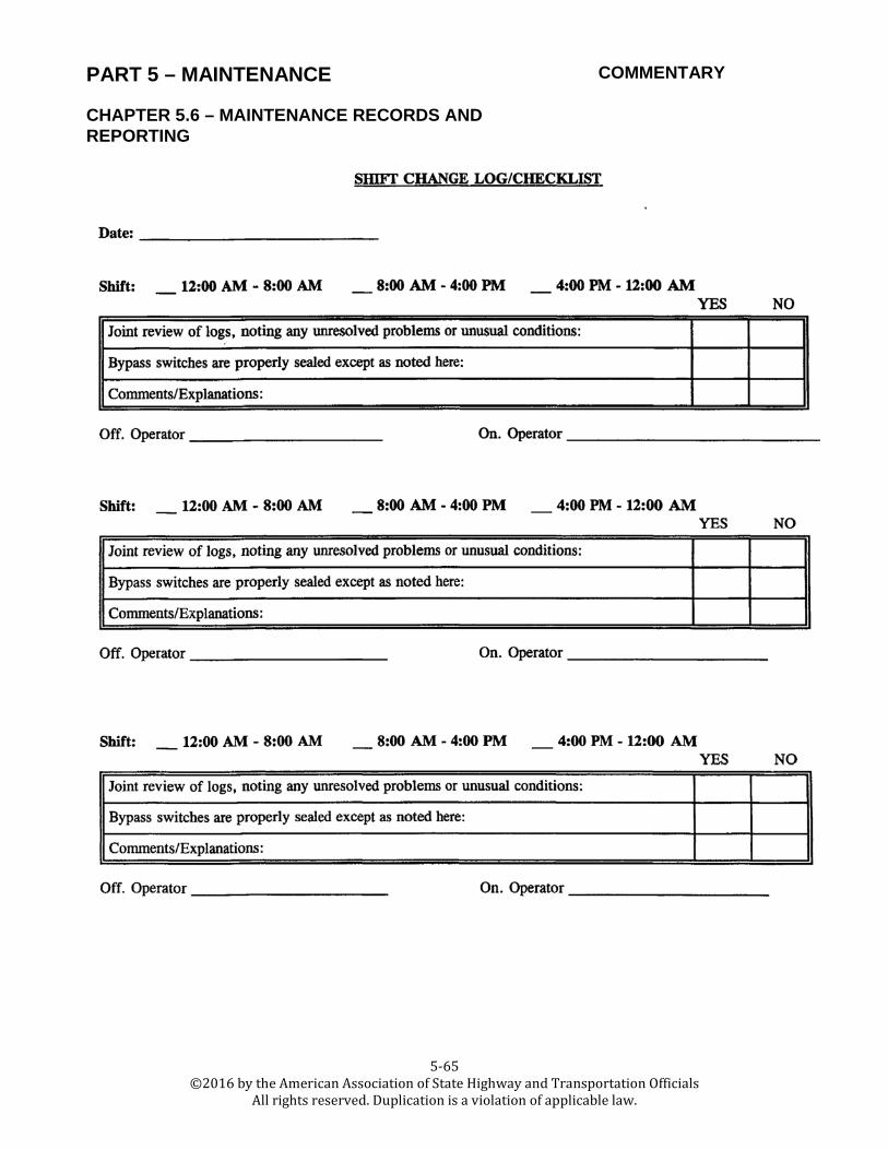
PART 5 – MAINTENANCE COMMENTARY
5-65 ©2016 by the American Association of State Highway and Transportation Officials
All rights reserved. Duplication is a violation of applicable law.
CHAPTER 5.6 – MAINTENANCE RECORDS AND REPORTING

PART 5 – MAINTENANCE COMMENTARY
5-66 ©2016 by the American Association of State Highway and Transportation Officials
All rights reserved. Duplication is a violation of applicable law.

PART 5 – MAINTENANCE COMMENTARY
5-67 ©2016 by the American Association of State Highway and Transportation Officials
All rights reserved. Duplication is a violation of applicable law.

PART 5 – MAINTENANCE COMMENTARY
5-68 ©2016 by the American Association of State Highway and Transportation Officials
All rights reserved. Duplication is a violation of applicable law.
CHAPTER 5.6 – MAINTENANCE RECORDS AND REPORTING
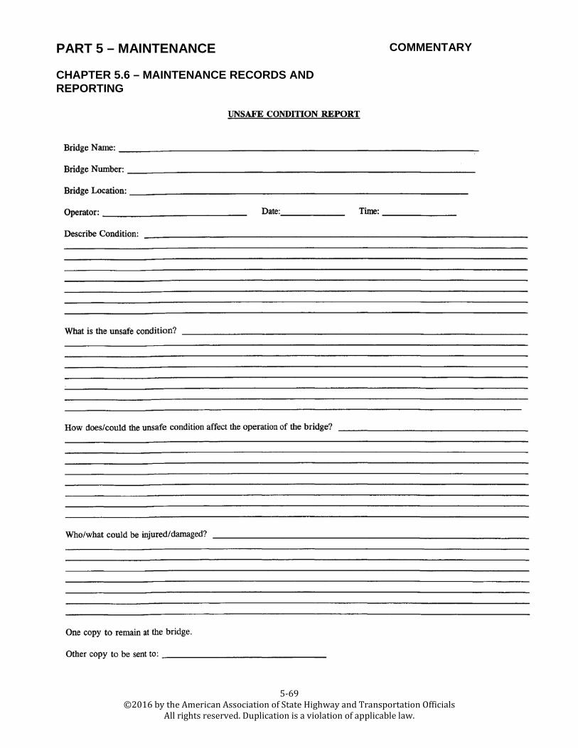
PART 5 – MAINTENANCE COMMENTARY
5-69 ©2016 by the American Association of State Highway and Transportation Officials
All rights reserved. Duplication is a violation of applicable law.
CHAPTER 5.6 – MAINTENANCE RECORDS AND REPORTING
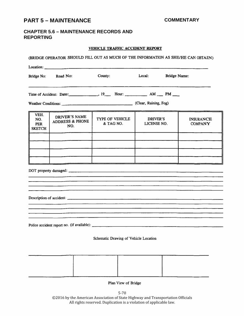
PART 5 – MAINTENANCE COMMENTARY
5-70 ©2016 by the American Association of State Highway and Transportation Officials
All rights reserved. Duplication is a violation of applicable law.
CHAPTER 5.6 – MAINTENANCE RECORDS AND REPORTING

PART 5 – MAINTENANCE COMMENTARY
5-71 ©2016 by the American Association of State Highway and Transportation Officials
All rights reserved. Duplication is a violation of applicable law.
CHAPTER 5.6 – MAINTENANCE RECORDS AND REPORTING

PART 5 – MAINTENANCE COMMENTARY
5-72 ©2016 by the American Association of State Highway and Transportation Officials
All rights reserved. Duplication is a violation of applicable law.

PART 5 – MAINTENANCE COMMENTARY
5-73 ©2016 by the American Association of State Highway and Transportation Officials
All rights reserved. Duplication is a violation of applicable law.

PART 5 – MAINTENANCE COMMENTARY
5-74 ©2016 by the American Association of State Highway and Transportation Officials
All rights reserved. Duplication is a violation of applicable law.

PART 5 – MAINTENANCE COMMENTARY
5-75 ©2016 by the American Association of State Highway and Transportation Officials
All rights reserved. Duplication is a violation of applicable law.

PART 5 – MAINTENANCE COMMENTARY
5-76 ©2016 by the American Association of State Highway and Transportation Officials
All rights reserved. Duplication is a violation of applicable law.

PART 5 – MAINTENANCE COMMENTARY
5-77 ©2016 by the American Association of State Highway and Transportation Officials
All rights reserved. Duplication is a violation of applicable law.

PART 5 – MAINTENANCE COMMENTARY
5-78 ©2016 by the American Association of State Highway and Transportation Officials
All rights reserved. Duplication is a violation of applicable law.

PART 5 – MAINTENANCE COMMENTARY
5-79 ©2016 by the American Association of State Highway and Transportation Officials
All rights reserved. Duplication is a violation of applicable law.

PART 5 – MAINTENANCE COMMENTARY
5-80 ©2016 by the American Association of State Highway and Transportation Officials
All rights reserved. Duplication is a violation of applicable law.
CHAPTER 5.6 – MAINTENANCE RECORDS AND REPORTING

PART 5 – MAINTENANCE COMMENTARY
5-81 ©2016 by the American Association of State Highway and Transportation Officials
All rights reserved. Duplication is a violation of applicable law.
CHAPTER 5.6 – MAINTENANCE RECORDS AND REPORTING

PART 5 – MAINTENANCE COMMENTARY
5-82 ©2016 by the American Association of State Highway and Transportation Officials
All rights reserved. Duplication is a violation of applicable law.

PART 5 – MAINTENANCE COMMENTARY
5-83 ©2016 by the American Association of State Highway and Transportation Officials
All rights reserved. Duplication is a violation of applicable law.

PART 5 – MAINTENANCE COMMENTARY
5-84 ©2016 by the American Association of State Highway and Transportation Officials
All rights reserved. Duplication is a violation of applicable law.
CHAPTER 5.6 – MAINTENANCE RECORDS AND REPORTING