
TABLE OF CONTENTS · output of the detector is an electrical pulse. Gamma rays also react with the...
35
Rev 11/08 9.1-i USNRC HRTD TABLE OF CONTENTS 9.1 EXCORE NEUTRON MONITORING SYSTEM .................................................... 1 9.1.1 Introduction ................................................................................................ 1 9.1.2 Detector Theory ......................................................................................... 3 9.1.3 Detector Locations ..................................................................................... 4 9.1.4 Wide Range Logarithmic Channel Basic Description ................................. 5 9.1.5 Wide Range Logarithmic Detectors............................................................ 5 9.1.6 Wide Range Logarithmic Power Circuitry................................................... 7 9.1.6.1 Charge Amplifier and Pre-amplifier .............................................. 7 9.1.6.2 Pulse Counting Circuitry .............................................................. 8 9.1.6.3 Campbelling Circuitry ................................................................... 8 9.1.6.4 Summing Amplifier ....................................................................... 9 9.1.6.5 Circuit Summary .......................................................................... 9 9.1.6.6 Rate Amplifier .............................................................................. 9 9.1.6.7 Bistables .................................................................................... 10 9.1.6.8 Calibration and Testing .............................................................. 10 9.1.7 Linear Power Range Safety Channels General Information..................... 11 9.1.8 Uncompensated Ion Chamber ................................................................. 11 9.1.9 Linear Power Range Safety Channel Circuitry ......................................... 12 9.1.9.1 Linear Amplifiers ........................................................................ 12 9.1.9.2 Power Summer .......................................................................... 12 9.1.9.3 Deviation Comparator ................................................................ 13 9.1.9.4 Comparator Averager ................................................................ 13 9.1.9.5 Calibration and Testing .............................................................. 13 9.1.9.6 High Voltage Power Supply ....................................................... 14 9.1.10 Power Range Linear Control Channels .................................................... 14 9.1.11 Summary.................................................................................................. 15
Transcript of TABLE OF CONTENTS · output of the detector is an electrical pulse. Gamma rays also react with the...

Rev 11/08 9.1-i USNRC HRTD
TABLE OF CONTENTS
9.1 EXCORE NEUTRON MONITORING SYSTEM .................................................... 1
9.1.1 Introduction ................................................................................................ 1
9.1.2 Detector Theory ......................................................................................... 3
9.1.3 Detector Locations ..................................................................................... 4
9.1.4 Wide Range Logarithmic Channel Basic Description ................................. 5
9.1.5 Wide Range Logarithmic Detectors ............................................................ 5
9.1.6 Wide Range Logarithmic Power Circuitry ................................................... 7 9.1.6.1 Charge Amplifier and Pre-amplifier .............................................. 7 9.1.6.2 Pulse Counting Circuitry .............................................................. 8 9.1.6.3 Campbelling Circuitry ................................................................... 8 9.1.6.4 Summing Amplifier ....................................................................... 9 9.1.6.5 Circuit Summary .......................................................................... 9 9.1.6.6 Rate Amplifier .............................................................................. 9 9.1.6.7 Bistables .................................................................................... 10 9.1.6.8 Calibration and Testing .............................................................. 10
9.1.7 Linear Power Range Safety Channels General Information ..................... 11
9.1.8 Uncompensated Ion Chamber ................................................................. 11
9.1.9 Linear Power Range Safety Channel Circuitry ......................................... 12 9.1.9.1 Linear Amplifiers ........................................................................ 12 9.1.9.2 Power Summer .......................................................................... 12 9.1.9.3 Deviation Comparator ................................................................ 13 9.1.9.4 Comparator Averager ................................................................ 13 9.1.9.5 Calibration and Testing .............................................................. 13 9.1.9.6 High Voltage Power Supply ....................................................... 14
9.1.10 Power Range Linear Control Channels .................................................... 14
9.1.11 Summary .................................................................................................. 15
Rev 11/08 9.1-ii USNRC HRTD
LIST OF FIGURES
Figure 9.1-1 Typical Channel Flux Coverage With Detectors
Figure 9.1-2 Ion Pairs Versus Applied Voltage
Figure 9.1-3 Excore Detector Location
Figure 9.1-4 Typical B10 Proportional Counter
Figure 9.1-5 Fission Chamber (Neutron Sensitivity 0.7 counts/NV)
Figure 9.1-6 Excore NI Wide Range Logarithmic Channel Block Diagram
Figure 9.1-7 Uncompensated Ionization Chamber
Figure 9.1-8 Excore NI Narrow Range Linear Channel Block Diagram
Figure 9.1-9 Linear Power Control Channel Block Diagram

Rev 11/08 9.1-1 USNRC HRTD
9.1 EXCORE NEUTRON MONITORING SYSTEM
Learning Objectives:
1. List the purposes of the excore nuclear instrumentation system.
2. Explain the basic operation of the following excore neutron detectors and state the detector type used in each range of the excore neutron monitoring system: a. B10 proportional counter b. Fission chamber c. Uncompensated Ion chamber
3. Describe the following excore nuclear instrumentation system interfaces and interlocks: a. Wide range logarithmic channel high voltage interlock b. Wide range logarithmic channel and linear power range safety channel
overlap. c. Wide range channel and linear power range safety channel reactor protection
system (RPS) inputs. d. Non-safety related linear power range safety channel interfaces.
4. Explain how the excore nuclear instrumentation is capable of detecting both radial and axial power distributions.
5. Explain how the linear power range safety channel is calibrated to indicate reactor thermal power.
6. List the power range linear control channel outputs.
9.1.1 Introduction
The purposes of the excore neutron monitoring system are to: 1. Monitor neutron flux from the source level to 200% of full power, 2. Provide indication in the control room of neutron power and the rate of change
of neutron power, 3. Provide power level signals to the Reactor Regulating System (RRS), 4. Provide power level signals and the rate of change of power signals to the
Reactor Protection System (RPS), and 5. Provide information on axial power distribution to the control room and the
RPS.
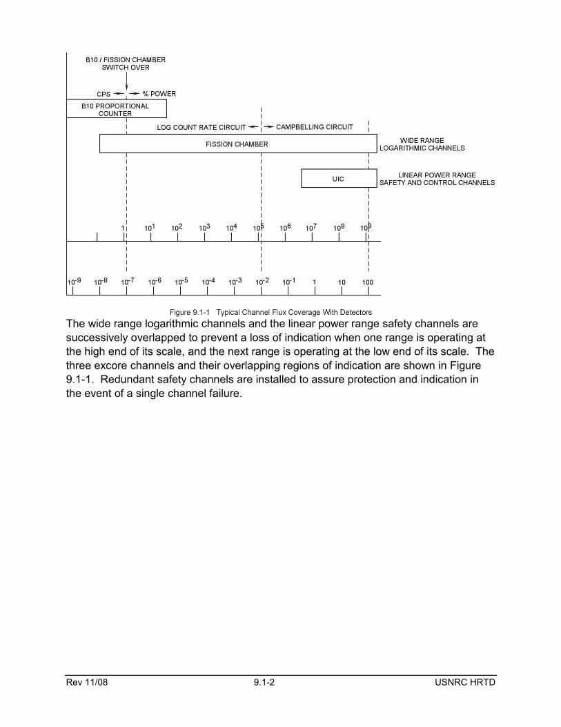
The excore neutron monitoring system senses leakage neutron levels from 10-9% to 200% power. In order to accurately cover this enormous region, the excore system is divided into the wide range logarithmic and linear power range safety channels. In addition, a non-safety related power range linear control channel is provided. The wide range logarithmic channel provides indication from 10-9% to 200% power and also provides start-up rate indication and inputs to the RPS. The linear power range safety channels provide indication of power from 1% to 200% power and supplies trip signals to the RPS. Finally the power range linear control channel provides indication of reactor power from 1% to 125% power and supplies an input to the RRS.
Rev 11/08 9.1-2 USNRC HRTD
The wide range logarithmic channels and the linear power range safety channels are successively overlapped to prevent a loss of indication when one range is operating at the high end of its scale, and the next range is operating at the low end of its scale. The three excore channels and their overlapping regions of indication are shown in Figure 9.1-1. Redundant safety channels are installed to assure protection and indication in the event of a single channel failure.

Rev 11/08 9.1-3 USNRC HRTD
9.1.2 Detector Theory
Radiation can be placed into three basic categories: 1. Charged particles (alpha, beta, protons), 2. Uncharged particles (neutrons), and 3. Electromagnetic radiation (gamma rays).
For most radiation detection systems, charged particles are collected within a detector. These particles are either counted or measured to provide a usable output signal. Since only charged particles can be detected, neutrons must interact within the medium of the detector to produce charged particles.
A gas detector curve (Figure 9.1-2) shows how ion pairs collected varies with the applied voltage. A charged particle ionizes the gas within the detector which produces ion pairs. The positive charges are drawn to the negative voltage
electrode while the negative charges migrate to the positive electrode.
In the recombination region (region I), the charge current will increase as the applied voltage is increased because less ion pairs are capable of recombining with higher voltage.
In the ionization chamber region (region II), the ions move too fast for recombination to occur. The charge current is constant because all ion pairs produced are collected. The gas amplification factor in this region is unity. The power range linear safety channel and linear control channel uncompensated ion chambers operate in this region. Also, the wide range logarithmic channel fission chamber operates in this region.
A further increase of applied voltage will cause a proportional increase of ion pairs collected in the proportional counter region (region III). The proportional increase is a result of the original ion pairs causing secondary ionization or an avalanche effect. The gas amplification factor can be as high as 106 in this region. The B10 detector used in the wide range logarithmic channel operates in the proportional counter region.
Eventually the gas amplification will become space charge limited at the electrodes with an observed fall off of the proportional relationship between ion pairs and applied voltage. The fall off occurs in the limited proportional region (region IV). Region IV is seldom used in radiation detection.
Rev 11/08 9.1-4 USNRC HRTD
The Geiger-Muller region (region V) is where the detector current is independent of the primary ion pair and incident radiation energy level. The detector completely discharges for any ion pair formed. Some portable gamma detectors operate in region V.
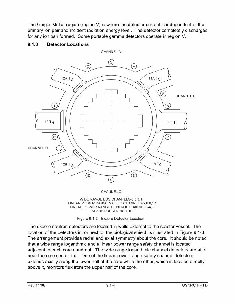
9.1.3 Detector Locations
The excore neutron detectors are located in wells external to the reactor vessel. The location of the detectors in, or next to, the biological shield, is illustrated in Figure 9.1-3. The arrangement provides radial and axial symmetry about the core. It should be noted that a wide range logarithmic and a linear power range safety channel is located adjacent to each core quadrant. The wide range logarithmic channel detectors are at or near the core center line. One of the linear power range safety channel detectors extends axially along the lower half of the core while the other, which is located directly above it, monitors flux from the upper half of the core.

Rev 11/08 9.1-5 USNRC HRTD
9.1.4 Wide Range Logarithmic Channel Basic Description
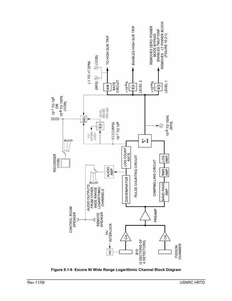
The four wide range logarithmic channels provide indication of power level from the source levels (0.1 counts per second) to 200% power. However, only the range from 0.1 cps to 150% power is displayed in the control room. Two different types of detectors, two circuits, and two indicating ranges are required to cover this large range of neutron flux. Each of the channels is supplied with inputs from B10 proportional counters and a fission chamber. The input signal is processed by a pulse counting circuit and a Campbelling circuit. Finally, the indication from the wide range logarithmic channel is displayed in counts per second (cps) and percent power.
9.1.5 Wide Range Logarithmic Detectors
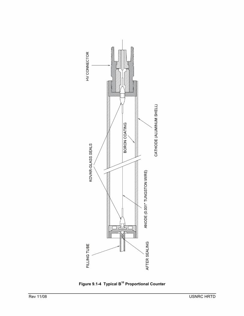
In the source level and low power region, the wide range logarithmic channel utilizes a B10 proportional detector to enhance the sensitivity of the channel. The B10 detector is more sensitive than the fission chamber in this area of operation. The B10 detector (Figure 9.1-4) consists of a central anode surrounded by an aluminum cylinder. The inside of the aluminum cylinder is coated with B10. When a neutron enters the detector, it reacts with the boron producing an alpha particle and a lithium nucleus. These particles are created with a kinetic energy of between 2.3 and 2.78 MeV. As these highly energetic particles travel through the gas contained within the detector assembly, many ion pairs are created. The positive charges are drawn to the negatively charged cylinder, while the negative charges are collected by the central anode. The resultant output of the detector is an electrical pulse. Gamma rays also react with the detector’s boron lining. Gamma rays react with matter through Compton’s scattering, the photoelectric effect, and pair production. Each of these mechanisms produces an electron, therefore, the charge produced inside of the detector by secondary ionization is small.
Each channel contains two B10 assemblies with four detectors in each assembly. The four detectors are connected in parallel to increase channel sensitivity. The output from the proportional counters is used in the extended range of indication. The extended range corresponds to flux levels from 10-9% power to 10-4% power. Extended range indicating lamps, located on the RPS cabinets, are energized when power level is in this range. High voltage to the B10 detectors is removed when power reaches 1000 counts
Rev 11/08 9.1-6 USNRC HRTD
per second (~10-7% power). The removal of high voltage prevents damaging the detector due to the large number of ionizations occurring.

Rev 11/08 9.1-7 USNRC HRTD
In addition to the B10 proportional detector input, each wide range logarithmic channel also receives an input from a fission chamber. The fission chamber (Figure 9.1-5) is internally coated with uranium oxide that has been enriched to greater than 90% U235. When a neutron enters the detector, a fission reaction occurs. This reaction results in two highly charged fission fragments that create secondary ionization in the argon-nitrogen fill gas and a charge is generated. The output of the fission chamber is used in the pulse counting circuit and the Campbelling circuit.
9.1.6 Wide Range Logarithmic Power Circuitry
9.1.6.1 Charge Amplifier and Pre-amplifier
The outputs of each proportional counter assembly and the fission chamber are fed individually to a charge amplifier and then to a pre-amplifier located in the containment

Rev 11/08 9.1-8 USNRC HRTD
building. A charge amplifier for each input signal is provided to minimize the effects of combined detector capacitance on the signal characteristics.
The pre-amplifier increases the signal to noise ratio of the detector outputs and transmits the signal to the RPS cabinets located in the control room. Provisions are made to insert a test signal to check pre-amplifier calibration and cable continuity.
9.1.6.2 Pulse Counting Circuitry
The log count rate circuitry consists of a discriminator, a log count rate amplifier, and receives its input from the pre-amplifier. The discriminator functions to remove gamma and noise from the input signal. Since the gamma pulse is approximately 1/6 the size of the neutron pulse, elimination of the signal is accomplished by setting a minimum voltage level for processing. This minimum voltage level is greater than the voltage pulses due to gammas and noise; therefore, only the neutron signal passes to the log count rate amplifier.
In addition to supplying an input to the log count rate circuit, the discriminator also supplies an output to the audible count rate indication. The audible count rate circuitry may be supplied from any one of the four wide range logarithmic channels and consists of two speakers (one in the control room and the other in the containment building) and an audio amplifier. The audible count rate is proportional to the neutron flux being sensed by the detector and can be divided by a frequency select switch. Thus, the final audio tone varies with the count rate and the frequency division selected. The audible count rate circuitry is required to be in operation during refueling and may be used during reactor startups.
The log count rate amplifier converts the neutron pulses into a logarithmic signal. A logarithmic signal is required to allow accurate resolution of the wide range of neutron flux indication.
The output of the log count rate amplifier is routed to a local meter at the RPS cabinets, a summing amplifier, the “level sense” bistable, and, via a selector switch, a control board meter and recorder. The local meter indication is calibrated in counts per second (cps) and has a range of 0.1 to 104 cps. The summing amplifier sums the outputs of the pulse counting circuitry and the campbelling circuitry (see section 9.1.6.4). The status of the level sense bistable determines the range of indication selected for the control board meter (see section 9.1.6.7). The control board meter is a dual indicator; the left-hand side is calibrated in cps with a range of 0.1 to 104 cps, and the right-hand side is calibrated in percent power with a range of 10-8 to 150%. The input to the cps half of the meter is supplied by the log count rate amplifier; the input to the percent power half is supplied by the summing amplifier. Indicating lamps are energized to inform the operator of active circuitry.
9.1.6.3 Campbelling Circuitry
The Campbelling circuitry consists of a bandpass amplifier, a root-mean-squared (rms) voltage amplifier, and a logarithmic amplifier.

Rev 11/08 9.1-9 USNRC HRTD
The Campbelling circuitry makes use of a condition called pulse pileup. The pulses are occurring at such a rate that they are piling on top of one another. If the output of the pre-amplifier is examined, one would see an erratic wave form with peaks and valleys. The higher the power level, the larger the amplitude of the peaks and valleys from the mean. In accordance with Campbell’s Theorem, the root mean square (rms) value of the pre-amplifiers’s output voltage is proportional to the average pulse rate from the detector. Processing the output from the pre-amplifier through an rms amplifier thus yields a signal proportional to power.
The bandpass amplifier is used to set the initial operating point of the Campbelling circuit. This is accomplished by setting the frequency of the ac voltage that will be passed to the remainder of the circuitry. From the bandpass amplifier, the signal is routed to the rms amplifier where the signal becomes proportional to power. The logarithmic amplifier is used to convert the output of the rms amplifier to a logarithmic signal. A logarithmic signal is required to allow accurate resolution of the wide range of neutron flux indication. The Campbelling circuit is used when flux levels are between 10-2% and 150% power. The output of the Campbelling circuit is combined with the output of the pulse counting circuit in the summing amplifier.
9.1.6.4 Summing Amplifier
The summing amplifier combines the output of the pulse counting circuit with the Campbelling circuit and supplies a rate circuit and two bistables. The output of the summing amplifier is also supplied to a selector switch that is used to select the desired wide range logarithmic signal for display on a control board meter and recorder.
9.1.6.5 Circuit Summary
When the reactor is shutdown and the neutron flux is at the source level, the wide range logarithmic channel is receiving its input from the B10 proportional detectors, processing its input via the pulse counting circuitry, and displaying its output on the dual indicators. The dual indicators are indicating power level on the extended range (cps). A typical reading for this condition is 10 to 30 cps. The next evolution is to take the reactor critical by CEA withdrawal. As the critical approach is made, flux increases, and the fission chamber begins to contribute to the pulse counting circuit's display. At 1000 cps, the B10 detector high voltage is removed and the dual indicators are shifted to the % power display. At this point, the fission chamber is supplying the entire pulse counting circuit input. This mode of operation continues until power is escalated to 10-2%. At 10-2%, the pulse counting circuit begins to saturate, and the Campbelling circuit will provide flux information, via the summing amplifier, to the remainder of the wide range logarithmic channel circuitry. The Campbelling circuitry functions to provide flux indication from 10-2 to 150% power for display on a control board meter and recorder.
9.1.6.6 Rate Amplifier
The rate amplifier differentiates the logarithmic power signal obtained from the summing amplifier to provide a rate of change of reactor power (startup rate) to indication and protection circuits. Startup rate indication with a meter range of -1 to +7 decades per minute (DPM) is provided on indicators in the control room and RPS cabinets.
Rev 11/08 9.1-10 USNRC HRTD
A high startup rate reactor trip will be generated if the startup rate exceeds 2.6 DPM and reactor power is between 10-4% and 15%. A pre-trip and associated control element assembly withdrawal prohibit (CWP) is generated if startup rate exceeds 1.5 DPM. Safety analysis does not take credit for the CWP; therefore, it is not safety related.
9.1.6.7 Bistables
Three bistables, two of which receive inputs from the summing amplifier and one which receives its input from the pulse counting circuitry, are used in each wide range logarithmic channel.
1. The Level One Bistable deenergizes when reactor power is above 10-4%. When the bistable de-energizes, the following occurs: • The reactor protection system (RPS) zero power mode bypass is
removed. The zero power mode bypass inhibits the thermal margin low pressure (TMLP) and low RCS flow reactor trips. The zero power mode bypass also institutes the ΔT power block. With the ΔT power block in effect, the selection of ΔT power by the TMLP calculator is prevented.
• The TMLP CWP is enabled. 2. The Level Two Bistable deenergizes when reactor power is above 10-4%.
When the bistable de-energizes, the startup rate trip is enabled. 3. The Level Sense Bistable deenergizes at 1000 cps. When the bistable
deenergizes, high voltage is removed from the B10 proportional detectors and wide range logarithmic indication shifts from the cps mode to the percent power mode.
9.1.6.8 Calibration and Testing
All of the wide range logarithmic circuitry, with the exception of the detectors and pre-amplifier, is located in the RPS cabinets. The calibration and test circuitry is also located in the RPS and consists of a seven-position operate/calibrate switch and a level trip test switch for the level instrumentation, and an operate/calibrate switch and a rate trip test switch for the rate instrumentation.
The level circuitry is tested by sequentially selecting each of six discrete signals with the operate/calibrate switch (the seventh position is the operate position). The signal is generated by a crystal oscillator in the wide range logarithmic RPS drawer. The switch is selected to the desired position, a signal is injected by the oscillator circuitry, and the indication is monitored to determine if the circuitry responded correctly to the injection of the test signal. With the level trip test switch the operator can add to the selected discrete calibrating signal and thus can check the setpoints of the power level bistables.
The startup rate circuit is checked by taking the operate/calibrate switch to calibrate and observing a +7 DPM meter indication. Leaving the switch in the operate position and utilizing the rate trip test switch, a ramp signal is used to check the set points of the startup rate pre-trip and trip bistables.
Rev 11/08 9.1-11 USNRC HRTD
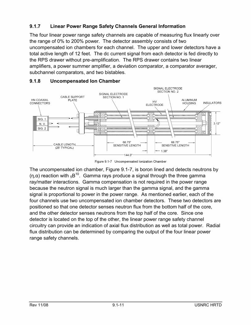
9.1.7 Linear Power Range Safety Channels General Information
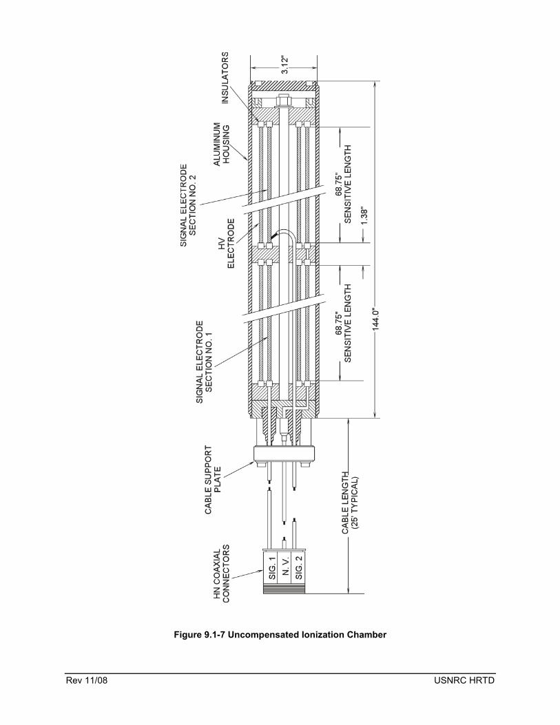
The four linear power range safety channels are capable of measuring flux linearly over the range of 0% to 200% power. The detector assembly consists of two uncompensated ion chambers for each channel. The upper and lower detectors have a total active length of 12 feet. The dc current signal from each detector is fed directly to the RPS drawer without pre-amplification. The RPS drawer contains two linear amplifiers, a power summer amplifier, a deviation comparator, a comparator averager, subchannel comparators, and two bistables.
9.1.8 Uncompensated Ion Chamber
The uncompensated ion chamber, Figure 9.1-7, is boron lined and detects neutrons by (η,α) reaction with 5B
10. Gamma rays produce a signal through the three gamma ray/matter interactions. Gamma compensation is not required in the power range because the neutron signal is much larger than the gamma signal, and the gamma signal is proportional to power in the power range. As mentioned earlier, each of the four channels use two uncompensated ion chamber detectors. These two detectors are positioned so that one detector senses neutron flux from the bottom half of the core, and the other detector senses neutrons from the top half of the core. Since one detector is located on the top of the other, the linear power range safety channel circuitry can provide an indication of axial flux distribution as well as total power. Radial flux distribution can be determined by comparing the output of the four linear power range safety channels.
Rev 11/08 9.1-12 USNRC HRTD
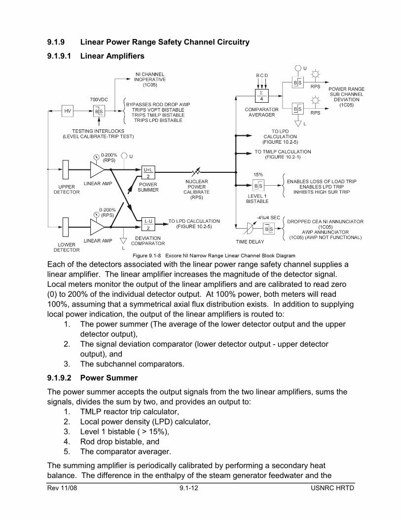
9.1.9 Linear Power Range Safety Channel Circuitry
9.1.9.1 Linear Amplifiers
Each of the detectors associated with the linear power range safety channel supplies a linear amplifier. The linear amplifier increases the magnitude of the detector signal. Local meters monitor the output of the linear amplifiers and are calibrated to read zero (0) to 200% of the individual detector output. At 100% power, both meters will read 100%, assuming that a symmetrical axial flux distribution exists. In addition to supplying local power indication, the output of the linear amplifiers is routed to:
1. The power summer (The average of the lower detector output and the upper detector output),
2. The signal deviation comparator (lower detector output - upper detector output), and
3. The subchannel comparators.
9.1.9.2 Power Summer
The power summer accepts the output signals from the two linear amplifiers, sums the signals, divides the sum by two, and provides an output to:
1. TMLP reactor trip calculator, 2. Local power density (LPD) calculator, 3. Level 1 bistable ( > 15%), 4. Rod drop bistable, and 5. The comparator averager.
The summing amplifier is periodically calibrated by performing a secondary heat balance. The difference in the enthalpy of the steam generator feedwater and the

Rev 11/08 9.1-13 USNRC HRTD
steam generator exit steam is multiplied by the mass flow rate of feedwater to determine the heat transferred from the reactor coolant system to the steam generator. This is then converted to power, and the summing amplifier is adjusted to indicate the actual power from the calculation.
The output of the power summer is compared with ΔT power in the TMLP calculator and the higher of the two power signals is used in the calculation of the TMLP trip set point and in the Variable Over Power Trip (VOPT).
The output of the power summer is also supplied to the Linear Power Density (LPD) calculator. The LPD calculator uses the signal in the calculation of Axial Shape Index (ASI) and in the determination of the LPD trip set point.
There are two bistables that are controlled by the output of the summing amplifier: 1. The Level 1 Bistable de-energizes above 15% power to enable the LPD and
loss of load reactor trips and inhibit the high startup rate reactor trip. 2. The Rod Drop Bistable senses a rapid decrease in power by comparing the
present power to power that has been processed through a time delay circuit. If the change is large enough (>4% in a 4 second period), the bistable trips. When the bistable trips, an automatic withdrawal prohibit (AWP) signal is transmitted to the control element drive control system and control room alarms are annunciated. The AWP is not safety-related.
9.1.9.3 Deviation Comparator
The deviation comparator circuit accepts outputs from both linear amplifiers, determines the difference between the output of the linear amplifiers, divides the difference by two, and transmits the resulting signal to the LPD calculator. The deviation comparator output is used by the LPD calculator to generate ASI. The ASI signal is used in the calculation of LPD.
9.1.9.4 Comparator Averager
The comparator averager receives inputs from the power summer of all four linear power range safety channels and averages the signals. The average signal is supplied to the subchannel comparators where it is compared with the output of each linear amplifier. Local and control room annunciators are actuated if the deviation from the average exceeds a predetermined value. This is a non safety-related signal.
9.1.9.5 Calibration and Testing
Each linear power range safety channel is equipped with four switches and associated test circuitry which verifies the accuracy of the meter circuitry and allows testing of trip set points. Each channel detector has an associated level calibrate switch and test trip switch. The switches are located on the linear power range safety channel drawer. Each level calibrate switch is a three position switch (operate, zero, and calibrate) that is used to verify meter accuracy. In the operate position, detector input is supplied to the channel. The zero position is used to verify the meter indication for zero input. The calibrate position supplies a 200% signal used to verify meter full scale indication.
Rev 11/08 9.1-14 USNRC HRTD
Each trip test switch is a combination switch and potentiometer which adds a signal to the detector input signal to allow testing of the power range trip set points.
When any of the switches associated with the linear power range safety channel is placed in an abnormal position, an interlock trips the high voltage bistable. When the high voltage bistable is tripped, the TMLP, LPD, and VOPT reactor trips are de-energized.
9.1.9.6 High Voltage Power Supply
The high voltage power supply converts the drawer voltage into a high voltage dc output used for powering the uncompensated ion chambers. Each linear power range safety channel drawer is equipped with a zero (0) to 1000 Vdc meter which displays the power supply output. The high voltage can be adjusted from 450 to 1000 Vdc and is normally set at 750 Vdc. If voltage drops to 700 Vdc, the high voltage bistable trips.
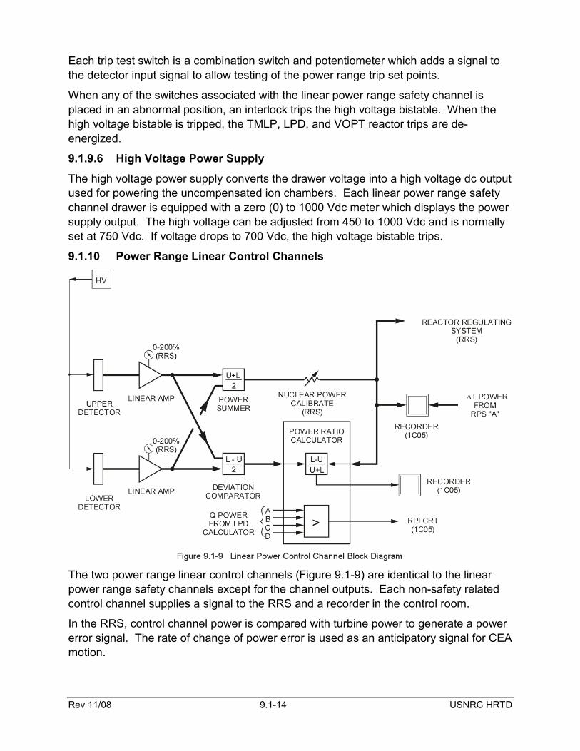
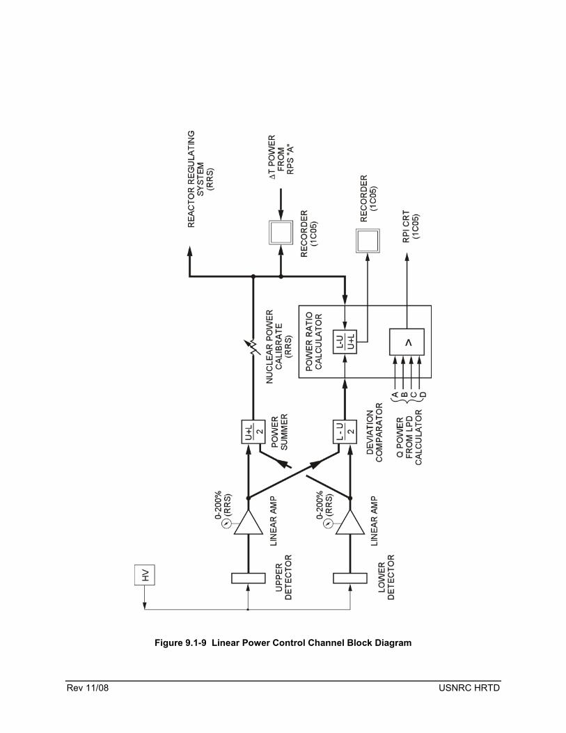
9.1.10 Power Range Linear Control Channels
The two power range linear control channels (Figure 9.1-9) are identical to the linear power range safety channels except for the channel outputs. Each non-safety related control channel supplies a signal to the RRS and a recorder in the control room.
In the RRS, control channel power is compared with turbine power to generate a power error signal. The rate of change of power error is used as an anticipatory signal for CEA motion.

Rev 11/08 9.1-15 USNRC HRTD
Two control room recorders, one for each power range control channel, are installed to display power level. In addition to nuclear power, each recorder also displays ΔT power from the RPS channel A TMLP calculation.
Separate control channel upper and lower detector signals are sent to a power ratio calculator. The power ratio calculator provides two functions:
1. The power ratio calculator calculates a backup indication of ASI from the control channel input. ASI is defined as (flux in the bottom one half of the core minus flux in the top one half of the core divided by total flux). The power ratio calculator supplies the ASI signal to a control room recorder. Potentiometers associated with the recorder allow the operator to set reference values and deviation limits for the ASI signal. The limits are derived from figures of allowable ASI in plant technical specifications.
2. The power ratio calculator also selects the highest Q power (Q power is the highest of ΔT power or nuclear power from the four LPD calculators). The power signal is used to generate pre-power dependent insertion limit (PPDIL) and Power Dependent Insertion Limit Alarms (PDIL). These alarms help ensure that the CEAs are maintained at the proper position
9.1.11 Summary
The excore neutron monitoring system consists of the safety-related wide range logarithmic channels, the safety-related linear power range safety channel, and the non-safety related power range linear control channel. These instruments provide indication of neutron power from the source level to 200% full power. The wide range logarithmic power channel supplies a high startup rate reactor trip signal to the RPS, and the linear power range safety channel provides a TMLP reactor trip input, a high reactor power reactor trip signal, a loss of load reactor trip input, and an input signal to the LPD reactor trip. The power range linear control channel provides a power signal to the RRS and indication of ASI.


Rev 11/08 USNRC HRTD
Figure 9.1-1 Typical Channel Flux Coverage With Detectors

Rev 11/08 USNRC HRTD

Rev 11/08 USNRC HRTD
Figure 9.1-2 Ion Pairs Versus Applied Voltage

Rev 11/08 USNRC HRTD

Rev 11/08 USNRC HRTD
Figure 9.1-3 Excore Detector Location

Rev 11/08 USNRC HRTD
Rev 11/08 USNRC HRTD
Figure 9.1-4 Typical B10 Proportional Counter

Rev 11/08 USNRC HRTD

Rev 11/08 USNRC HRTD
Figure 9.1-5 Fission Chamber (Neutron Sensitivity 0.7 counts/NV)

Rev 11/08 USNRC HRTD
Rev 11/08 USNRC HRTD
Figure 9.1-6 Excore NI Wide Range Logarithmic Channel Block Diagram

Rev 11/08 USNRC HRTD
Rev 11/08 USNRC HRTD
Figure 9.1-7 Uncompensated Ionization Chamber

Rev 11/08 USNRC HRTD

Rev 11/08 USNRC HRTD
Figure 9.1-8 Excore NI Narrow Range Linear Channel Block Diagram

Rev 11/08 USNRC HRTD
Rev 11/08 USNRC HRTD
Figure 9.1-9 Linear Power Control Channel Block Diagram