Table of Contents - Solarbotics.netsolarbotics.net/starting/200207_sintra/sintra_manual.pdfTable of...
48
Table of Contents 1 Table of Contents . . . . . . . . . . . . . . . . . . . . . . . . . . . . . . . . . . . . . . . . . . . . . . . 1 Introduction . . . . . . . . . . . . . . . . . . . . . . . . . . . . . . . . . . . . . . . . . . . . . . . . . . . . . . . . . . . . . . . . 2 Section I: How To Finish, Form and Fabricate Painting and Edge Treatment . . . . . . . . . . . . . . . . . . . . . . . . . . . . . . . . . . . . . . . . . . . . . . . . . . . 3 Screen Printing . . . . . . . . . . . . . . . . . . . . . . . . . . . . . . . . . . . . . . . . . . . . . . . . . . . . . . . . . . . . . 6 Adhesive Decals and Vinyl Graphics . . . . . . . . . . . . . . . . . . . . . . . . . . . . . . . . . . . . . . . . . . . . . 8 Adhesive Bonding . . . . . . . . . . . . . . . . . . . . . . . . . . . . . . . . . . . . . . . . . . . . . . . . . . . . . . . . . . . 8 Photomounting . . . . . . . . . . . . . . . . . . . . . . . . . . . . . . . . . . . . . . . . . . . . . . . . . . . . . . . . . . . . . . 11 Hot Air Welding . . . . . . . . . . . . . . . . . . . . . . . . . . . . . . . . . . . . . . . . . . . . . . . . . . . . . . . . . . . . . 14 Heat Bending . . . . . . . . . . . . . . . . . . . . . . . . . . . . . . . . . . . . . . . . . . . . . . . . . . . . . . . . . . . . . . . 15 Die Cutting . . . . . . . . . . . . . . . . . . . . . . . . . . . . . . . . . . . . . . . . . . . . . . . . . . . . . . . . . . . . . . . . . 18 Thermoforming . . . . . . . . . . . . . . . . . . . . . . . . . . . . . . . . . . . . . . . . . . . . . . . . . . . . . . . . . . . . . . 20 Ultrasonic Welding . . . . . . . . . . . . . . . . . . . . . . . . . . . . . . . . . . . . . . . . . . . . . . . . . . . . . . . . . . . 22 Cutting, Drilling and Finishing . . . . . . . . . . . . . . . . . . . . . . . . . . . . . . . . . . . . . . . . . . . . . . . . . . . 23 Section II: Attachment and Fastening Basic Comments . . . . . . . . . . . . . . . . . . . . . . . . . . . . . . . . . . . . . . . . . . . . . . . . . . . . . . . . . . . . 27 Temperature Fluctuations, Expansion and Contraction . . . . . . . . . . . . . . . . . . . . . . . . . . . . . . . . 27 Exterior Signs . . . . . . . . . . . . . . . . . . . . . . . . . . . . . . . . . . . . . . . . . . . . . . . . . . . . . . . . . . . . . . . 30 Screwed Joints . . . . . . . . . . . . . . . . . . . . . . . . . . . . . . . . . . . . . . . . . . . . . . . . . . . . . . . . . . . . . . 30 Riveted Joints . . . . . . . . . . . . . . . . . . . . . . . . . . . . . . . . . . . . . . . . . . . . . . . . . . . . . . . . . . . . . . . 31 Frame Fastening . . . . . . . . . . . . . . . . . . . . . . . . . . . . . . . . . . . . . . . . . . . . . . . . . . . . . . . . . . . . 31 Concealed Fastening . . . . . . . . . . . . . . . . . . . . . . . . . . . . . . . . . . . . . . . . . . . . . . . . . . . . . . . . . 33 Section III: Engineering Specifications Sheet Dimension Tolerances . . . . . . . . . . . . . . . . . . . . . . . . . . . . . . . . . . . . . . . . . . . . . . . . . . . 34 Gauge (Thickness) Tolerances . . . . . . . . . . . . . . . . . . . . . . . . . . . . . . . . . . . . . . . . . . . . . . . . . . 34 Gauge vs. Weight and Density . . . . . . . . . . . . . . . . . . . . . . . . . . . . . . . . . . . . . . . . . . . . . . . . . . 34 Impact vs. Thickness . . . . . . . . . . . . . . . . . . . . . . . . . . . . . . . . . . . . . . . . . . . . . . . . . . . . . . . . . 34 Sintra Material Specifications . . . . . . . . . . . . . . . . . . . . . . . . . . . . . . . . . . . . . . . . . . . . . . . . . . . 35 Airborne Sound Insulation . . . . . . . . . . . . . . . . . . . . . . . . . . . . . . . . . . . . . . . . . . . . . . . . . . . . . . 36 Linear Expansion/Contraction . . . . . . . . . . . . . . . . . . . . . . . . . . . . . . . . . . . . . . . . . . . . . . . . . . . 36 Thermal Insulting Properties . . . . . . . . . . . . . . . . . . . . . . . . . . . . . . . . . . . . . . . . . . . . . . . . . . . . 37 Load Capacity . . . . . . . . . . . . . . . . . . . . . . . . . . . . . . . . . . . . . . . . . . . . . . . . . . . . . . . . . . . . . . 37 Section IV: Chemical Resistance Resistance to Standard Reagents . . . . . . . . . . . . . . . . . . . . . . . . . . . . . . . . . . . . . . . . . . . . . . . . 38 Rigid P.V.C. Type 1 Qualification Testing . . . . . . . . . . . . . . . . . . . . . . . . . . . . . . . . . . . . . . . . . . . 39 Section V: Weatherability General Comments . . . . . . . . . . . . . . . . . . . . . . . . . . . . . . . . . . . . . . . . . . . . . . . . . . . . . . . . . . 40 Specific Effects of Outdoor Exposure . . . . . . . . . . . . . . . . . . . . . . . . . . . . . . . . . . . . . . . . . . . . . 40 Section VI: Fire Characteristics Fire Test for Foamed Plastics Used for Decorative Purposes . . . . . . . . . . . . . . . . . . . . . . . . . . . 41 Fire Test Results . . . . . . . . . . . . . . . . . . . . . . . . . . . . . . . . . . . . . . . . . . . . . . . . . . . . . . . . . . . . . 42 Relative Flammability Comparisons to Other Materials . . . . . . . . . . . . . . . . . . . . . . . . . . . . . . . . 43 Section VII: Sources . . . . . . . . . . . . . . . . . . . . . . . . . . . . . . . . . . . . . . . . . . . . . . . . . . 44
Transcript of Table of Contents - Solarbotics.netsolarbotics.net/starting/200207_sintra/sintra_manual.pdfTable of...
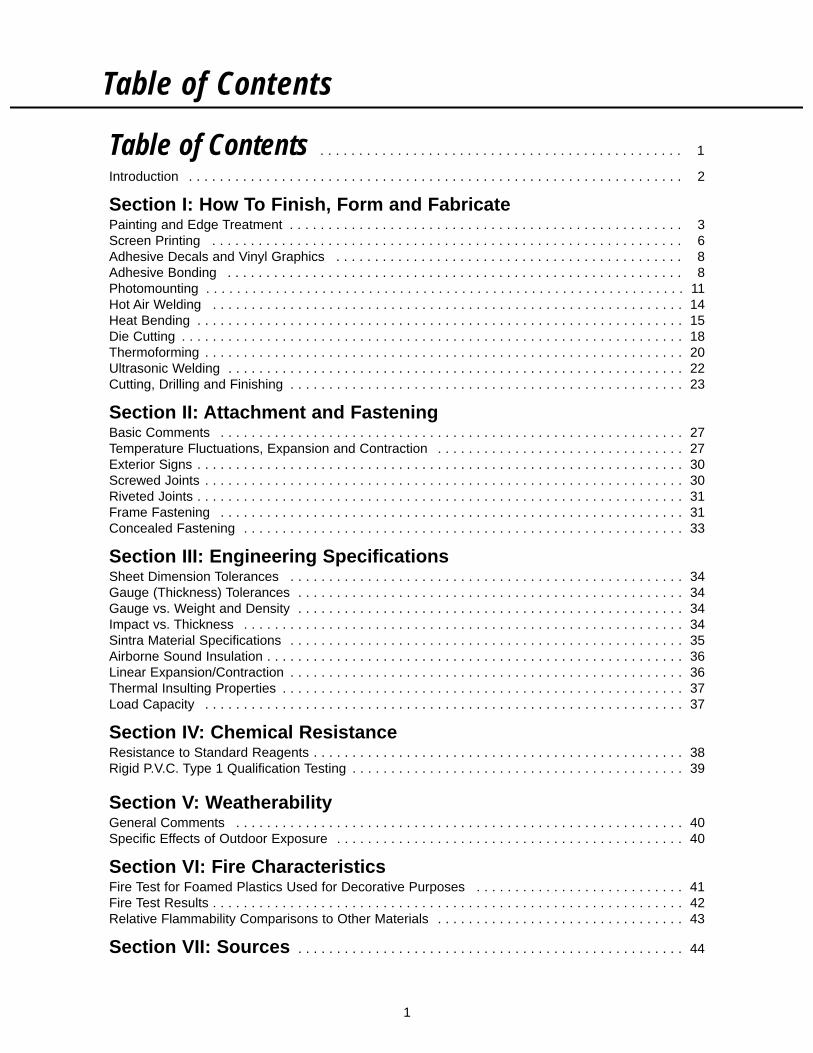
Table of Contents
1
Table of Contents . . . . . . . . . . . . . . . . . . . . . . . . . . . . . . . . . . . . . . . . . . . . . . . 1
Introduction . . . . . . . . . . . . . . . . . . . . . . . . . . . . . . . . . . . . . . . . . . . . . . . . . . . . . . . . . . . . . . . . 2
Section I: How To Finish, Form and FabricatePainting and Edge Treatment . . . . . . . . . . . . . . . . . . . . . . . . . . . . . . . . . . . . . . . . . . . . . . . . . . . 3Screen Printing . . . . . . . . . . . . . . . . . . . . . . . . . . . . . . . . . . . . . . . . . . . . . . . . . . . . . . . . . . . . . 6Adhesive Decals and Vinyl Graphics . . . . . . . . . . . . . . . . . . . . . . . . . . . . . . . . . . . . . . . . . . . . . 8Adhesive Bonding . . . . . . . . . . . . . . . . . . . . . . . . . . . . . . . . . . . . . . . . . . . . . . . . . . . . . . . . . . . 8Photomounting . . . . . . . . . . . . . . . . . . . . . . . . . . . . . . . . . . . . . . . . . . . . . . . . . . . . . . . . . . . . . . 11Hot Air Welding . . . . . . . . . . . . . . . . . . . . . . . . . . . . . . . . . . . . . . . . . . . . . . . . . . . . . . . . . . . . . 14Heat Bending . . . . . . . . . . . . . . . . . . . . . . . . . . . . . . . . . . . . . . . . . . . . . . . . . . . . . . . . . . . . . . . 15Die Cutting . . . . . . . . . . . . . . . . . . . . . . . . . . . . . . . . . . . . . . . . . . . . . . . . . . . . . . . . . . . . . . . . . 18Thermoforming . . . . . . . . . . . . . . . . . . . . . . . . . . . . . . . . . . . . . . . . . . . . . . . . . . . . . . . . . . . . . . 20Ultrasonic Welding . . . . . . . . . . . . . . . . . . . . . . . . . . . . . . . . . . . . . . . . . . . . . . . . . . . . . . . . . . . 22Cutting, Drilling and Finishing . . . . . . . . . . . . . . . . . . . . . . . . . . . . . . . . . . . . . . . . . . . . . . . . . . . 23
Section II: Attachment and FasteningBasic Comments . . . . . . . . . . . . . . . . . . . . . . . . . . . . . . . . . . . . . . . . . . . . . . . . . . . . . . . . . . . . 27Temperature Fluctuations, Expansion and Contraction . . . . . . . . . . . . . . . . . . . . . . . . . . . . . . . . 27Exterior Signs . . . . . . . . . . . . . . . . . . . . . . . . . . . . . . . . . . . . . . . . . . . . . . . . . . . . . . . . . . . . . . . 30Screwed Joints . . . . . . . . . . . . . . . . . . . . . . . . . . . . . . . . . . . . . . . . . . . . . . . . . . . . . . . . . . . . . . 30Riveted Joints . . . . . . . . . . . . . . . . . . . . . . . . . . . . . . . . . . . . . . . . . . . . . . . . . . . . . . . . . . . . . . . 31Frame Fastening . . . . . . . . . . . . . . . . . . . . . . . . . . . . . . . . . . . . . . . . . . . . . . . . . . . . . . . . . . . . 31Concealed Fastening . . . . . . . . . . . . . . . . . . . . . . . . . . . . . . . . . . . . . . . . . . . . . . . . . . . . . . . . . 33
Section III: Engineering SpecificationsSheet Dimension Tolerances . . . . . . . . . . . . . . . . . . . . . . . . . . . . . . . . . . . . . . . . . . . . . . . . . . . 34Gauge (Thickness) Tolerances . . . . . . . . . . . . . . . . . . . . . . . . . . . . . . . . . . . . . . . . . . . . . . . . . . 34Gauge vs. Weight and Density . . . . . . . . . . . . . . . . . . . . . . . . . . . . . . . . . . . . . . . . . . . . . . . . . . 34Impact vs. Thickness . . . . . . . . . . . . . . . . . . . . . . . . . . . . . . . . . . . . . . . . . . . . . . . . . . . . . . . . . 34Sintra Material Specifications . . . . . . . . . . . . . . . . . . . . . . . . . . . . . . . . . . . . . . . . . . . . . . . . . . . 35Airborne Sound Insulation . . . . . . . . . . . . . . . . . . . . . . . . . . . . . . . . . . . . . . . . . . . . . . . . . . . . . . 36Linear Expansion/Contraction . . . . . . . . . . . . . . . . . . . . . . . . . . . . . . . . . . . . . . . . . . . . . . . . . . . 36Thermal Insulting Properties . . . . . . . . . . . . . . . . . . . . . . . . . . . . . . . . . . . . . . . . . . . . . . . . . . . . 37Load Capacity . . . . . . . . . . . . . . . . . . . . . . . . . . . . . . . . . . . . . . . . . . . . . . . . . . . . . . . . . . . . . . 37
Section IV: Chemical ResistanceResistance to Standard Reagents . . . . . . . . . . . . . . . . . . . . . . . . . . . . . . . . . . . . . . . . . . . . . . . . 38Rigid P.V.C. Type 1 Qualification Testing . . . . . . . . . . . . . . . . . . . . . . . . . . . . . . . . . . . . . . . . . . . 39
Section V: WeatherabilityGeneral Comments . . . . . . . . . . . . . . . . . . . . . . . . . . . . . . . . . . . . . . . . . . . . . . . . . . . . . . . . . . 40Specific Effects of Outdoor Exposure . . . . . . . . . . . . . . . . . . . . . . . . . . . . . . . . . . . . . . . . . . . . . 40
Section VI: Fire CharacteristicsFire Test for Foamed Plastics Used for Decorative Purposes . . . . . . . . . . . . . . . . . . . . . . . . . . . 41Fire Test Results . . . . . . . . . . . . . . . . . . . . . . . . . . . . . . . . . . . . . . . . . . . . . . . . . . . . . . . . . . . . . 42Relative Flammability Comparisons to Other Materials . . . . . . . . . . . . . . . . . . . . . . . . . . . . . . . . 43
Section VII: Sources . . . . . . . . . . . . . . . . . . . . . . . . . . . . . . . . . . . . . . . . . . . . . . . . . . 44

2
IntroductionThis "How To" Manual has been developed to assist fabricators to work with Sintra® material in themost efficient and effective manner. The tips and suggestions contained in this manual are the resultof many years of combined experience by fabricators in both the U.S. and Europe.
These fabrication suggestions and product specifications are based on information which is, in ouropinion, reliable. However, since skill, judgment, and quality of equipment and tools are involved, andsince conditions and methods of using Sintra material are beyond our control, the suggestionscontained in this manual are provided without guarantee. We recommend that prospective usersdetermine the suitability of both the material and suggestions before adopting them on a commercialscale. ALUSUISSE COMPOSITES, INC., DOES NOT MAKE ANY WARRANTIES, EXPRESS ORIMPLIED, INCLUDING MERCHANTABILITY AND FITNESS FOR PURPOSE, WITH RESPECT TOANY SAID SUGGESTIONS AND PRODUCT DATA. In no event shall Alusuisse Composites, Inc.,have any liability in any way related to or arising out of said suggestions and product data for direct,special, consequential or any other damages of any kind regardless whether such liability is based onbreach of contract, negligence or other tort, or breach of any warranty, express or implied.
Also, normal safety and health precautions practiced in any fabricating environment should be usedwhen fabricating Sintra material.
MSDS for Sintra Material are available through our customer service department, call (800) 626-3365.
A UL RECOGNIZEDCOMPONENT®
Section I: How to Form, Finish and Fabricate
3
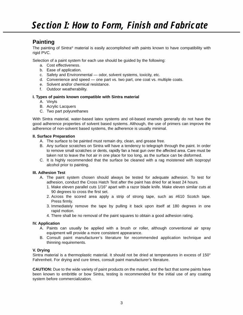
PaintingThe painting of Sintra® material is easily accomplished with paints known to have compatibility withrigid PVC.
Selection of a paint system for each use should be guided by the following:a. Cost effectiveness.b. Ease of application.c. Safety and Environmental — odor, solvent systems, toxicity, etc.d. Convenience and speed — one part vs. two part, one coat vs. multiple coats.e. Solvent and/or chemical resistance.f. Outdoor weatherability.
I. Types of paints known compatible with Sintra materialA. VinylsB. Acrylic LacquersC. Two part polyurethanes
With Sintra material, water-based latex systems and oil-based enamels generally do not have thegood adherence properties of solvent based systems. Although, the use of primers can improve theadherence of non-solvent based systems, the adherence is usually minimal.
II. Surface PreparationA. The surface to be painted must remain dry, clean, and grease free.B. Any surface scratches on Sintra will have a tendency to telegraph through the paint. In order
to remove small scratches or dents, rapidly fan a heat gun over the affected area. Care must betaken not to leave the hot air in one place for too long, as the surface can be disformed.
C. It is highly recommended that the surface be cleaned with a rag moistened with isopropylalcohol prior to painting.
III. Adhesion TestA. The paint system chosen should always be tested for adequate adhesion. To test for
adhesion, conduct the Cross Hatch Test after the paint has dried for at least 24 hours.1. Make eleven parallel cuts 1/16" apart with a razor blade knife. Make eleven similar cuts at
90 degrees to cross the first set.2. Across the scored area apply a strip of strong tape, such as #610 Scotch tape.
Press firmly.3. Immediately remove the tape by pulling it back upon itself at 180 degrees in one
rapid motion.4. There shall be no removal of the paint squares to obtain a good adhesion rating.
IV. ApplicationA. Paints can usually be applied with a brush or roller, although conventional air spray
equipment will provide a more consistent appearance.B. Consult paint manufacturer’s literature for recommended application technique and
thinning requirements.
V. DryingSintra material is a thermoplastic material. It should not be dried at temperatures in excess of 150°Fahrenheit. For drying and cure times, consult paint manufacturer’s literature.
CAUTION: Due to the wide variety of paint products on the market, and the fact that some paints havebeen known to embrittle or bow Sintra, testing is recommended for the initial use of any coatingsystem before commercialization.
4
Section I: How to Form, Finish and FabricateVI. Edge Treatment
When Sintra is cut to size during fabrication, edge cells are exposed. Although these cells donot allow paint or water to be absorbed any further than the first layer, the filling or chemicalcollapsing of these cells before painting can offer close to the same texture or appearance asthe surface of the sheet after painting.
A. Filling exposed cells (10-19 mm)Spot putty or glazing compound used in the auto body industry works very well.1. Fill edge cells with spot putty using a stiff, flat blade. Fill the cells, do not build up the edge.2. When dry, usually 3-4 minutes, sand lightly to remove blade marks and any build up of
putty.
B. Collapsing exposed cells (1-6 mm)Use a PVC solvent such as, Methyl Ethyl Ketone (MEK) or Tetrahydrofuran (THF).1. Sand edge of Sintra to remove all saw or router marks.2. Apply PVC solvent to sanded edge with acrylic glue applicator bottle. With protected
finger, rub solvent onto edge of Sintra. The more you apply and rub, the more cells youcollapse.
C. Edge BandingFor thicker Sintra Material panels, 1 mm or 2 mm Sintra Material can be adhered to theedge using a PVC solvent.
D. Aluminum or plastic edge extrusions ("U" Channels, T-Moldings)
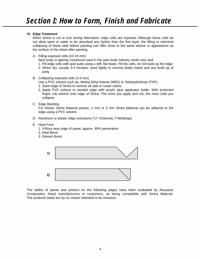
E. Heat Form1. V-Rout near edge of panel, approx. 90% penetration2. Heat Bend3. Solvent Bond
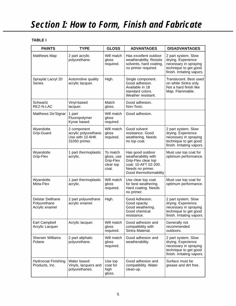
The tables of paints and primers on the following pages have been evaluated by AlusuisseComposites, listed manufacturers or customers, as being compatible with Sintra Material.The products listed are by no means intended to be inclusive.
1)
2)
5
Section I: How to Form, Finish and Fabricate
PAINTS TYPE GLOSS ADVANTAGES DISADVANTAGES
Matthews Map 2 part acrylic Will match Has excellent outdoor 2 part system. Slowpolyurethane. gloss weatherability. Resists drying. Experience
required. solvents, hard coating, necessary in sprayingno primer required. technique to get good
finish. Irritating vapors.
Spraylat Lacryl 20 Automotive quality High. Single component. Translucent. Best usedSeries acrylic lacquer. Good adhesion. on white Sintra only.
Available in 18 Not a hard finish likestandard colors. Map. Flammable.Weather resistant.
Schwartz Vinyl-based Match Good adhesion.REZ-N-LAC lacquer. gloss. Non-Toxic.
Matthews De’Signar 1 part Will match Good adhesion.Fluoropolymer glossKynar based. required.
Wyandotte 2 component Will match Good solvent 2 part system. SlowGrip-Guard acrylic polyurethane. gloss resistance. Good drying. Experience
Use with 10 AHK required. weathering. Needs necessary in spraying31050 primer. no top coat. technique to get good
finish. Irritating vapors.
Wyandotte 1 part thermoplastic To match Has good outdoor Must use top coat forGrip-Flex acrylic. gloss, use weatherability with optimum performance.
Grip-Flex Grip-Flex clear topclear top coat: 10-AFT 02-200.coat. Needs no primer.
Good thermoformability
Wyandotte 1 part thermoplastic Will match Use clear top coat Must use top coat forMeta-Flex acrylic. gloss for best weathering. optimum performance.
required. Hard coating. Needsno primer.
Delstar Delthane 2 part polyurethane High. Good Adhesion. 2 part system. SlowPolyurethane acrylic enamel. Good opacity. drying. ExperienceAcrylic enamel Good weathering. necessary in spraying
Good chemical technique to get goodresistance. finish. Irritating vapors.
Earl Campbell Acrylic lacquer. Will match Good adhesion and Generally notAcrylic Lacquer gloss compatibility with recommended
required. Sintra Material. outdoors.
Sherwin Williams 2 part aliphatic Will match Good adhesion and 2 part system. SlowPolane polyurethane. gloss weatherability. drying. Experience
required. necessary in sprayingtechnique to get goodfinish. Irritating vapors.
Hydrocoat Finishing Water based: Use top Good adhesion and Surface must beProducts, Inc. Vinyls, lacquers and coat for compatibility. Water grease and dirt free.
polyurethanes. high clean-up.gloss.
TABLE I
6
Section I: How to Form, Finish and Fabricate
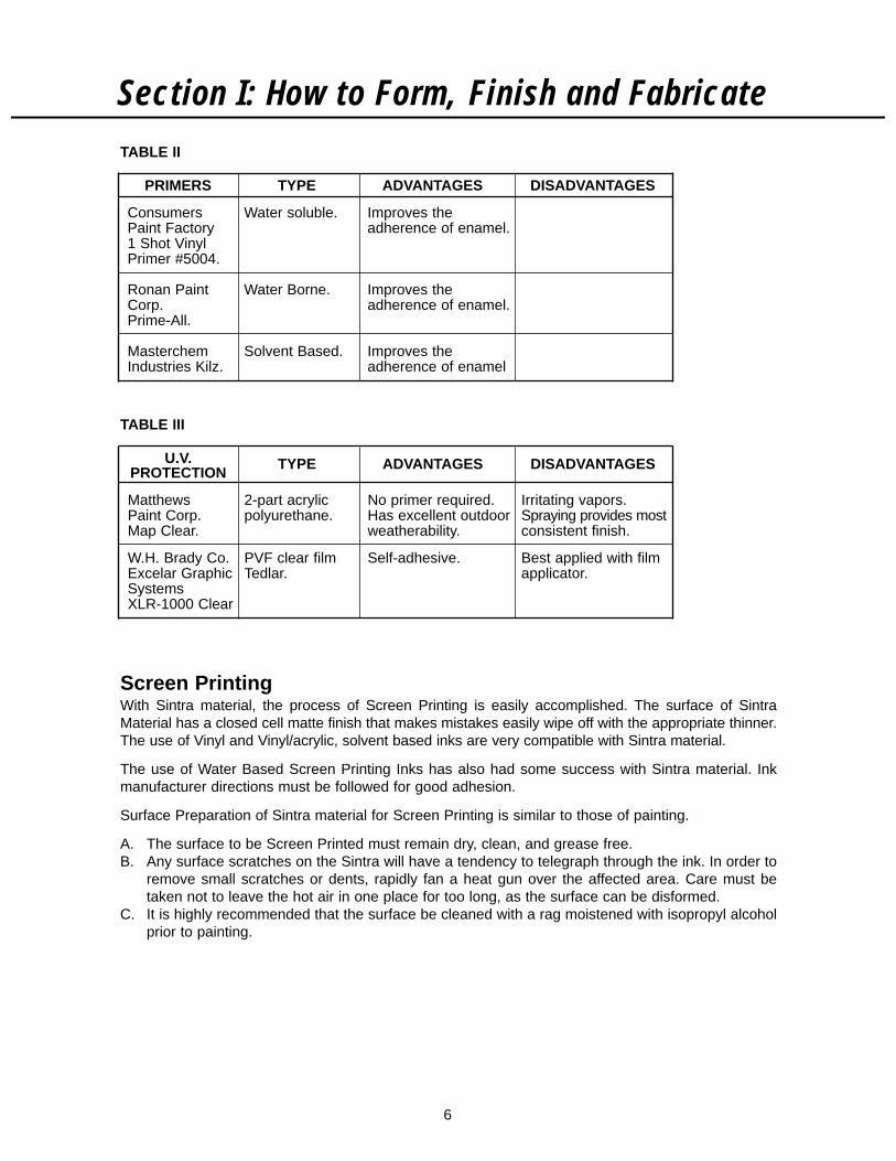
Screen PrintingWith Sintra material, the process of Screen Printing is easily accomplished. The surface of SintraMaterial has a closed cell matte finish that makes mistakes easily wipe off with the appropriate thinner.The use of Vinyl and Vinyl/acrylic, solvent based inks are very compatible with Sintra material.
The use of Water Based Screen Printing Inks has also had some success with Sintra material. Inkmanufacturer directions must be followed for good adhesion.
Surface Preparation of Sintra material for Screen Printing is similar to those of painting.
A. The surface to be Screen Printed must remain dry, clean, and grease free.B. Any surface scratches on the Sintra will have a tendency to telegraph through the ink. In order to
remove small scratches or dents, rapidly fan a heat gun over the affected area. Care must betaken not to leave the hot air in one place for too long, as the surface can be disformed.
C. It is highly recommended that the surface be cleaned with a rag moistened with isopropyl alcoholprior to painting.
PRIMERS TYPE ADVANTAGES DISADVANTAGES
Consumers Water soluble. Improves thePaint Factory adherence of enamel.1 Shot VinylPrimer #5004.
Ronan Paint Water Borne. Improves theCorp. adherence of enamel.Prime-All.
Masterchem Solvent Based. Improves theIndustries Kilz. adherence of enamel
TABLE II
U.V. TYPE ADVANTAGES DISADVANTAGESPROTECTION
Matthews 2-part acrylic No primer required. Irritating vapors.Paint Corp. polyurethane. Has excellent outdoor Spraying provides mostMap Clear. weatherability. consistent finish.
W.H. Brady Co. PVF clear film Self-adhesive. Best applied with filmExcelar Graphic Tedlar. applicator.SystemsXLR-1000 Clear
TABLE III

7
Section I: How to Form, Finish and Fabricate
The above mentioned screen printing inks should be tested in a manner which duplicates your printingprocess before initiating production.
It is strongly recommended to consult the appropriate ink manufacturer regarding any required inkadditives such as catalyst for proper adhesion and exterior usage.
Screen Printing ink should air dry rather than be heat dried. Temperatures in excess of 150° Fahrenheitmay cause warping or bowing of Sintra material.
Most U.V. Screen Printing Inks that are compatible with rigid PVC will work on Sintra material. The mostimportant factor to be considered when using U.V. systems is the curing oven. Low wattage bulbsshould be used to keep the temperature below 150° Fahrenheit. The use of U.V. curing systems, whichhave variable speed conveyers are considered the best type to use with Sintra material.
MANUFACTURER INK CURING TYPE
Deco-Chem ATX AirMFX AirEPO AirURE AirPRP UV
Ink Dezyne VP AirMP AirUI UV
Naz-Dar / KC 9700 Air7700 AirS2 AirGV AirPP Air
3700 UV2700 Air
Sericol PFMR UVMR Matte UVFascure UV
Gloss Poly UVXG AirPM AirPY Air
Summit Zephyr-Jet AirUVRP UV
T.W. Graphics WB-2000 Air
TABLE IV — SCREEN PRINTING INKS
8
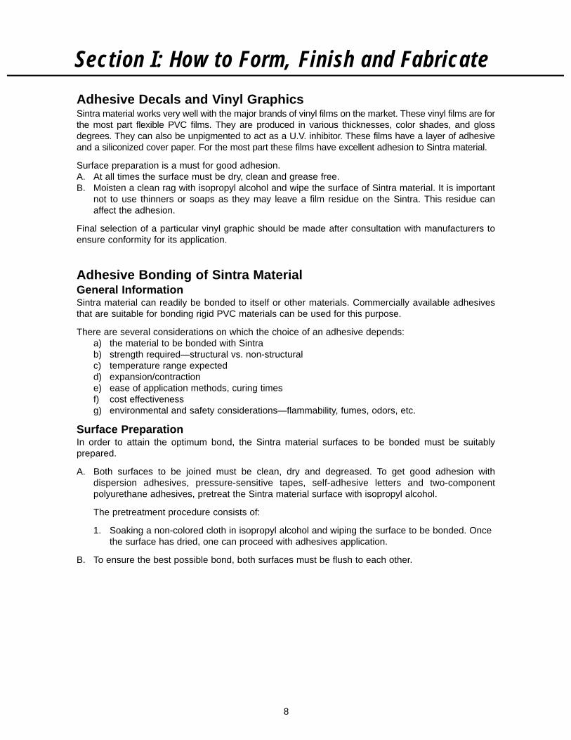
Adhesive Decals and Vinyl GraphicsSintra material works very well with the major brands of vinyl films on the market. These vinyl films are forthe most part flexible PVC films. They are produced in various thicknesses, color shades, and glossdegrees. They can also be unpigmented to act as a U.V. inhibitor. These films have a layer of adhesiveand a siliconized cover paper. For the most part these films have excellent adhesion to Sintra material.
Surface preparation is a must for good adhesion.A. At all times the surface must be dry, clean and grease free.B. Moisten a clean rag with isopropyl alcohol and wipe the surface of Sintra material. It is important
not to use thinners or soaps as they may leave a film residue on the Sintra. This residue canaffect the adhesion.
Final selection of a particular vinyl graphic should be made after consultation with manufacturers toensure conformity for its application.
Adhesive Bonding of Sintra MaterialGeneral InformationSintra material can readily be bonded to itself or other materials. Commercially available adhesivesthat are suitable for bonding rigid PVC materials can be used for this purpose.
There are several considerations on which the choice of an adhesive depends: a) the material to be bonded with Sintra b) strength required—structural vs. non-structural c) temperature range expected d) expansion/contraction e) ease of application methods, curing times f) cost effectiveness g) environmental and safety considerations—flammability, fumes, odors, etc.
Surface PreparationIn order to attain the optimum bond, the Sintra material surfaces to be bonded must be suitablyprepared.
A. Both surfaces to be joined must be clean, dry and degreased. To get good adhesion withdispersion adhesives, pressure-sensitive tapes, self-adhesive letters and two-componentpolyurethane adhesives, pretreat the Sintra material surface with isopropyl alcohol.
The pretreatment procedure consists of:
1. Soaking a non-colored cloth in isopropyl alcohol and wiping the surface to be bonded. Once the surface has dried, one can proceed with adhesives application.
B. To ensure the best possible bond, both surfaces must be flush to each other.
Section I: How to Form, Finish and Fabricate

9
Selection of AdhesivesThe selection of the proper adhesive for a job depends on the materials to be joined, as well as theend use and other considerations mentioned earlier.
The following suggestions serve as general guidelines.
A. Bonding Sintra Material to Sintra Material
1. For edge bonding and joining parts made of Sintra material, use a PVC solvent such as(THF, MEK, cyclohexanone solvent systems). Make sure the solvent is fresh—it can loseeffectiveness with storage.
2. For bonding large areas: If using PVC solvent such as pipe cement, spread with notchedtrowel and work rapidly. One can also use adhesives recommended for non-porous materials.
B. Bonding Sintra Material to Non-Porous Solid MaterialFor non-porous material such as PVC, other plastics or metal, the following types of adhesives may be used.
1. Contact adhesive with solvent:a. Neoprene, nitrile, polyurethane or other synthetic rubber types.b. Adhesive must be applied to both faces. Parallel beads of adhesive are often preferred
because it allows evaporation of solvent providing faster cure.c. For bonding Sintra material to flexible PVC sheets, only plasticizer-resistant types of
adhesives should be used.
C. Bonding Sintra Material to Porous Materials
For porous materials such as paper, textiles, fabrics or wood, the following adhesives may be used.1. Contact adhesive with solvent: Same systems as for non-porous materials.2. Construction mastic, structural silicone adhesives.
Considerations such as expected temperature ranges (expansion/contraction), substrate andsize of Sintra material panels should be taken into careful consideration when deciding on amethod of attachment.
D. Using Pressure Sensitive TapesPressure sensitive tapes can be used for:
1. Less demanding applications that are stress-free.2. To adhere parts during installation work.3. To hold parts while the primary adhesive is curing.
The following pressure sensitive tapes have been found to be compatible with Sintra material:
3M Corporation: Y 4945, Y 9473
Norton Company: V 2043
Rexham Industrial Films: Rexham Fluorex A/PS
The table of adhesives on the following page has been evaluated by Alusuisse Composites, listedmanufacturers or customers, as being compatible with Sintra Material. The products listed are in nomeans intended to be inclusive.
Section I: How to Form, Finish and Fabricate

10
Section I: How to Form, Finish and Fabricate
ADHESIVE TYPE ADVANTAGES DISADVANTAGES
Tetrahydrofuran (THF) PVC Solvent. Water thin, best Very fast evaporation. EDupont, Fisher applied with acrylic Unpleasant vapors.Scientific. glue applicator.Schwartz Chemical Co.
Parabond P28 all Solvent based. Softens surface Flammable. E E Epurpose cement allowing for stronger Unpleasant vapors.
bond.
Schwartz Solvent based. Softens surface Flammable. E E EChemical Co. allowing for stronger Unpleasant vapors.VC1 & VC2 bond.
IPS Weld on Solvent based. Softens surface Flammable. E EAdhesives allowing for stronger Unpleasant vapors.
bond.
Do-it or PVC Pipe PVC pipe cement Bond unaffected by Solvents highly E ECement (THF, MEK, water. flammable.P.C.I. cyclohexanone Unpleasant vapors.
solvent systems). Recommend usingmasks.
Universal Adhesive Synthetic rubber type Excellent all-around (Available in sign E E E E E ESealant with petroleum adhesive. supply stores or(TAN) distillate and acetone directly from the(TN 100) solvent base. manufacturer).
Duro Quick Gel Super Glue Quick bond. Good for Sets up too fast to E G G FLoctite Corp. (cyanoacrylate). joining small pieces. use on large pieces.
Foster 82-40 Neoprene contact Non-flammable. Not good for porous G F G F G Fcement (methylene surfaces like wood.chloride solvent system).
Bostik 4045 Nitrile rubber ketone Fast drying. Dries Flammable. E G G GBostik Corp. solvent. clear. Can be
precoated andstored. Retrackingwith MEK.
Fuller Max Synthetic rubber base Bonds to several Attacks the styrofoam EBond Adhesive with petroleum substrates. slightly. (Let it flash T.E.C. Corp. distillates. off first).
Kineco King Synthetic rubber Does not destroy the Not a structural G E15-165 base. polystyrene. adhesive.
Dow 795 Silicone type. Non-flammable. Slow curing (use E E E F G G GSilicone Building Easy to work with. double-faced tapeSealant for temporary bond).
Not readily availablein stores.
GE Silicone II Silicone type. Non-flammable. Slow curing. G G G G G GWindow and Easy to work with.Door Sealant Available in many
stores.
Scotch-Grip Neoprene contact Fast drying. Clear. Flammable. E G GPlastic Adhesive cement, ketone Resists water andNo. 4475 solvent. oils.
3M Spray Easy to apply. Flammable. EAdhesive 90 Quick to tack.
National Casein Water soluble. Non-flammable. Slow drying. Best for F F F EPVC-E Easy to apply. thick papers.
TABLE I — ADHESIVES
CODE: E — EXCELLENTG — GOODF — FAIR
SIN
TR
AM
AT
ER
IAL
WO
OD
AL
UM
INU
M
MA
SO
NR
Y
GA
LVA
NIZ
ED
ST
EE
L
DR
YW
AL
L
MO
ST
OTH
ER
PLA
STI
CS
FAB
RIC
S
PO
LYS
TY
RO
FO
AM
AC
RY
LIC
PAP
ER
GL
AS
S

11
PhotomountingSintra material’s surface and excellent adherence capacity make it one of the best materials availablefor photomounting. Whether you do small manual jobs or have a large, automated facility, here aresome tips on photomounting/lamination that might be of help.
Advantages of Sintra Material1. Sintra material’s texture won’t show through, in most cases.
2. Since Sintra material is a rigid material, finished mounts are stronger than mounts using cardboard or lighter foam-type substrates. Corners won’t bend and mountings won’t crease like othersubstrates. Therefore, Sintra can be shipped without damage if properly packaged.
3. After lamination, the mounted photo can be used as a component of a display. It may be routed,heat bent, drilled, screen printed and painted within the limitations of the photo.
4. Mounting is not limited to photos. Using the lamination process, Sintra is suitable for mountingresin coated (RC) photo papers, Cibachrome prints, posters, lithographs, blueprints, plastic-coated maps, rice paper, vellum, art papers, foils, tissues, newsprint and most paper.
Methods of Mounting/LaminatingSince Sintra material may warp at temperatures about 150° Fahrenheit, it cannot be dry or hot mounted.Cold mounting in cold roller laminators such as Warman-Greig, Greig or Sealeze presses, cold vacuummounting in VacuSeal presses, or hand lamination all give excellent results.
General Recommendations1. Getting Good Adhesion
a. Clean the Sintra material with isopropyl alcohol to remove any grease, fingerprints, etc.
b. To cold laminate pressure-sensitive adhesives, you need sufficient pressure, typically 25-40psi. You also must make sure that proper spacers are used. Because good laminationdepends on equal force exerted across the entire width of the material being laminated, thetop roll must move down evenly left and right. Even contact between the top and the bottomlaminating rolls is essential. To maintain even contact "zero the nip." Once the nip is zeroed,use spacer shims to preset the nip opening for a particular laminate.
c. Adequate pressure helps squeeze out air from between the adhesive, the Sintra materialand the print.
d. The bond obtained after 3 hours will generally allow for processing. Maximum bond is usuallyobtained within 24 hours after lamination.
e. To test adhesion, flex the finished mount. It should not come loose in the center.
f. Moisture can become trapped between layers of porous material (such as paper) and causeblisters. The level of moisture in the atmosphere should be reduced before press work.Prints may even have to be predried. Sintra material does not have to be predried becauseit is not porous, moreover, heating Sintra material above 150° Fahrenheit may cause warping.
When tacking prints to Sintra material, some shops will hang a number of tacked pieces inan upside-down position until they are ready to pass them through. As a precaution, it isadvisable not to hold them any longer than 10 minutes or the prints may absorb moisture,change in dimension and cause bubbles and wrinkles.
Section I: How to Form, Finish and Fabricate

12
2. Delaminating Bad Mountsa. Pressure-sensitive adhesives may be delaminated if done within 5 minutes after lamination.
The print will probably be ruined, but the Sintra material may be reused.
b. Beyond 5 minutes, the adhesive has set and other methods will have to be used, such as ahot air gun or a hair dryer to peel off the laminate. The remaining adhesive may be taken off with isopropyl alcohol or mineral spirits.
3. Avoiding Wrinkles and Surface Blemishesa. Wrinkles can be caused by misalignment of adhesive roll, too much pressure, or unparallel rolls.
b. Small bumps, particularly visible with Cibachrome or glossy prints, are caused by trappeddirt or hardened adhesive. Good housekeeping and an ionizing static eliminator on the pressare important to minimize dirt pick-up. During lamination, the back of the print should bechecked and wiped down before it is processed. If bumps are caused by hardened adhesive(cut open to check), use a fresh roll or sheet of transfer adhesive. To prevent strike-through,one might also consider using a print made with thicker paper (.007+).
4. Clear OverlaysClear high-gloss overlays enhance color and protect against fading indoors and outdoors. Toavoid blistering, do not use overlays, clear coatings, or sprays which contain solvents.
Lamination ProceduresThere are several techniques for cold lamination to Sintra material:
A) Cold lamination with presses using a separate transfer film B) Cold lamination with a press using paper with an adhesive backing C) Hand lamination using transfer adhesive D) Hand lamination using spray adhesive
The procedure for each is as follows:
A. Cold Lamination with a Press, Using a Transfer Adhesive FilmTransfer adhesives such as Permacolor "PermaPrint IP 2000," or "PermaPrint IP 3000," byMACtac Permacolor, or Sealeze "Print Mount" or "Print Mount Ultra" by Seal Products, Inc.
1. Apply transfer adhesive to either printed material or Sintra material:a. Pull off enough release paper from the top feed roll to do the lamination. Then pull the
adhesive film from the feed roll (sticky side up) and over the lamination roll so that it tackson to the piece to be precoated.
b. Pass the film and the piece through the nip.c. Trim off excess adhesive film around the piece. It now has a coating of transfer adhesive
on the back protected by a release paper.
2. Peel off a 1/2"–1" section of release paper from the upper edge of the piece and fold back.
3. Tack on the other material to be laminated (either an uncoated print to the precoated Sintramaterial or a precoated print to the uncoated Sintra material).
4. Feed tacked edge into nip rollers keeping printed piece bent away from Sintra material.
5. As it passed through the rollers, strip away the release paper. (Make sure there are nowrinkles or trapped dirt.)
Section I: How to Form, Finish and Fabricate

13
B. Cold Lamination with a Press, Using an Adhesive-Backed Paper1. Peel off a 1/2"–1" section of release paper from the upper edge of the preprinted adhesive
backed paper.
2. Tack on to Sintra material, lining up edges.
3. Set rollers at 40 psi pressure.
4. Feed tacked edge into nip of rollers keeping printed piece bent away from Sintra material.
5. As it passes through the rollers, strip away the release paper. (Make sure there are nowrinkles or trapped dirt.)
C. Hand Lamination Using a Transfer Adhesive1. Take a sheet of transfer adhesive (both sides covered by release paper) and fold back
release paper on one side approximately 1/2" from one edge.
2. Tack on edge of print to exposed adhesive.
3. Lift the print slightly, remove the rest of the release paper and use a roller or squeegee tosmooth the print onto the adhesive. The back of the print is now coated with an adhesivewhich is protected by release paper.
4. Before the lamination to Sintra material, remove excess air between print and adhesive. Thisis done by turning the print over so that the release paper is up and smoothing out from thecenter with a squeegee.
5. Now peel off approximately 1/2"–1" of release paper from upper edge and fold back.
6. Tack on to Sintra material, lining up edges.
7. Using a hand roller or squeegee, closely follow the removal of the liner to eliminate bubblescaused by air entrapment. Work with a small surface at a time (approximately 12").
8. Continue procedure number 7 (above) until the lamination is complete.
D. Hand Lamination Using a Spray Adhesive1. Spray adhesive on the back of the piece to be mounted. Spray 6"–8" away from the surface.
A double coat is best, with the second coat applied in a cross direction to the first coat. Forbonding most art materials, adhesive need only be applied to one surface, preferably the print.
2. Before mounting, allow 2–4 minutes to dry—the adhesive must be aggressively tacky. Ifthere are blisters due to trapped solvent, allow slightly longer than 4 minutes of drying time.
3. Position piece on Sintra material and smooth out to eliminate any wrinkles and trapped solvent.
Section I: How to Form, Finish and Fabricate

14
Hot Air WeldingSintra Material is a foamed PVC sheeting material and is therefore not well suited to hot air weldingwith a solid PVC welding rod. The effect of the heat required to melt the solid PVC welding rod hasdetrimental effect on the surface of the Sintra Material.
For this reason the preferred method of adhering Sintra Material to itself in corner applications isthrough the use of solvent based adhesives.
Section I: How to Form, Finish and Fabricate
TROUBLESHOOTING WHEN USING COLD LAMINATION PRESSES
PROBLEM CAUSED BY ACTION
Poor adhesion or a. Insufficient pressure. a. Increase lamination rollbubbles: pressure if running without
spacer shims. If using spacershims, use next smaller size.
b. Stripping back more than 1" b. Never strip back more thanof release paper while tacking 1" of release paper.on print traps air.
c. Premature contact between c. As it is fed through rolls, theprint and adhesive traps air. print should be tilted or bent
away from adhesive until itenters the nip.
d. The print contains moisture. d. Predry print and/or keephumidity at a low level.
Curl (bowing): a. Too much web tension. a. Reduce unwind brakepressure.
Wrinkles: a. Misalignment of adhesive roll, a. Shift the material roll on thecausing web tension. bar to release tension.
b. Top and bottom lamination b. Make sure spacer shims arerolls are not parallel. the same size, then zero the
nip.
c. Too much pressure. c. Reduce roll pressure.
d. Sintra material thickness d. If correctly sized spacer shimsrelative to shim thickness is are not available, zero the nip.too great (should be no morethan 1/32").
4. Place a clean sheet of Sintra material over laminated piece and weigh down for 15 minutes to obtain the maximum bond. Allow 24 hours before exposing the laminate to sudden temperature or humidity changes.

15
Heat BendingOne of the many advantages of Sintra material is that it can easily be bent by using localized heating.It is possible to cut sheets to final dimensions and perform some machining operations prior to heatbending. Spray painting, screen printing, machining, gluing and fastening operations can be performedafter heat bending.
When the above processing has been done, the part can be used in displays, signage, trade shows,displays or in many applications where a lightweight, curved part is desired. Other applications wouldinclude angles, channels and ducts.
Defining the Heat Bending ProcessMost rigid thermoplastic materials become soft and pliable when heated. After cooling, thesematerials again become rigid. This permits a variety of heat-forming techniques such as heat bending,vacuum forming and pressure forming.
Unlike vacuum forming, it is not possible to create an intricate shape with heat bending. However,relatively little thinning out of sheet gauge during heat bending is an advantage over vacuum and pressure forming.
The steps in the heat bending process are:
1. Heat the material in an area along the line where the bend is to be made. The width of the areais determined by the gauge of the sheet and the angle of the bend.
2. After the sheet has attained the proper flexibility, it is bent to obtain the desired radius and angle.
3. The part is held in position to cool. Cooling may be accelerated by contact with cold metal, amoist rag, compressed air or fans.
I. Heating ParametersThe characteristics of Sintra material, the thickness of the sheet, and the radius of the bend, willdetermine the method, time, temperature of heat and width of the heated area.
A. Characteristics of Sintra Material
As a moderately expanded rigid PVC, Sintra material requires less time to heat than solidmaterials. For optimum bending, the temperature of Sintra material should be in the range of250°–300° Fahrenheit.
In general, Sintra material should be allowed to "soak" (i.e., heated at a lower temperaturesetting for a longer period of time, instead of at a higher temperature for a shorter time).
B. Types of Heaters
Direct contact heating bars can be used for 2 mm through 6 mm Sintra material providing thesurface temperature of the bars is kept below 300° Fahrenheit. A higher temperature may meltthe surface or leave an unsightly impression on the sheet.
The sheet should be set directly on the bar to get better contact. Continue heating until thesheet is pliable enough to bend.
To avoid direct contact heating, one may prefer to purchase or construct an IR heater whichis slightly recessed below the surface of a table:
1. Nichrome heater wires, Calrod heaters, or silicone blanket heaters work for this use.
2. A rheostat must be used to adjust the intensity of the heat.
3. For Sintra material, 3 mm and thicker, the area to be bent should be heated from bothsides by alternately flipping it back and forth over the heater until the sheet becomes pliable.
Section I: How to Form, Finish and Fabricate

16
C. Effect of Thickness
As the thickness of the material increases, so does the total volume of the sheet to be heated.For this reason, different heating methods must be used for thicker sheets than for thinner-gauge material.
1. Heating time and temperature: Increase heating time approximately 75% per each 1 mmincrement in thickness. Keep the temperature setting constant.
2. Application of heat: With 1 mm and 2 mm, heat sheet on one side only—the side formingthe inside of bend. Above 2 mm, heat both sides; or heat one side, flip over, and heatreverse.
D. Effect of Radius
1. The following heating widths are recommended:
Very small radius ...................... 2 times the thickness of sheetAverage radius.......................... 3 times the thickness of sheetLarge radius.............................. 4 times the thickness of sheet
2. To obtain very large radii, the following techniques can be used:
a. Use Calrod heaters with reflectors to broaden heating area.b. Use hot air guns.c. Construct a heater to get a very wide heating area. Use a perforated steel sheet heated
with gas. Drape over waxed cardboard tube (sleek tube) to make bend.d. Silicone blanket heater used in conjunction with a rheostat to control heat.
3. To make very sharp bends.
a. Use a "V" groove 90 degree carbide router bit. Score the side of the sheet which formsthe inside corners. Typically route about halfway through for a 90 degree corner with aslight radius.
b. Heat the routed area until the sheet will flex easily.c. Bend the sheet and place in cooling guide.d. Apply PVC solvent to seam to add strength to the corner.
Section I: How to Form, Finish and Fabricate

17
II. Bending/CoolingA. Guides and Frames
A bending guide or frame can simply be a piece of wood or metal with the correct anglerequired for the part. To facilitate cooling, both the guide and table can be constructedof metal.
B. Bending
When the proper flexibility is attained, quickly remove the sheet from the heater. Positionand bend the heated area over the guide. If only one side is heated, the heated side formsthe inside of the bend.
Immobilize the part in the formed position until it has cooled.
To test whether or not the sheet has been sufficiently heated:
a. While the material is still being heated, hold one end of the sheet and flex the other end.b. When it flexes easily, proceed with bending.
C. Cooling is accomplished by ambient air or contact with a moist rag or cool metal. Fans orcompressed air can also be used to facilitate the cooling process.
The cooling time increases with the thickness and size of the part.
III. Other Heat Bending TechniquesIn addition to conventional heat bending, one could utilize a technique called drape forming. Inthis procedure, the whole sheet is first heated until pliable, then clamped to a mold and allowedto cool. If more sophisticated parts are desired, use a vacuum forming process.
Section I: How to Form, Finish and Fabricate
18
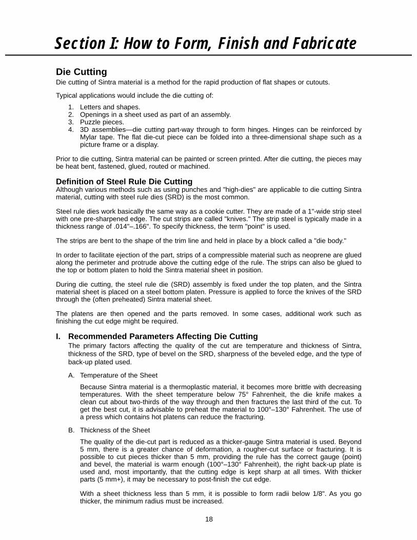
Die CuttingDie cutting of Sintra material is a method for the rapid production of flat shapes or cutouts.
Typical applications would include the die cutting of:
1. Letters and shapes.2. Openings in a sheet used as part of an assembly.3. Puzzle pieces.4. 3D assemblies—die cutting part-way through to form hinges. Hinges can be reinforced by
Mylar tape. The flat die-cut piece can be folded into a three-dimensional shape such as apicture frame or a display.
Prior to die cutting, Sintra material can be painted or screen printed. After die cutting, the pieces maybe heat bent, fastened, glued, routed or machined.
Definition of Steel Rule Die CuttingAlthough various methods such as using punches and "high-dies" are applicable to die cutting Sintramaterial, cutting with steel rule dies (SRD) is the most common.
Steel rule dies work basically the same way as a cookie cutter. They are made of a 1"-wide strip steelwith one pre-sharpened edge. The cut strips are called "knives." The strip steel is typically made in athickness range of .014"–.166". To specify thickness, the term "point" is used.
The strips are bent to the shape of the trim line and held in place by a block called a "die body."
In order to facilitate ejection of the part, strips of a compressible material such as neoprene are gluedalong the perimeter and protrude above the cutting edge of the rule. The strips can also be glued tothe top or bottom platen to hold the Sintra material sheet in position.
During die cutting, the steel rule die (SRD) assembly is fixed under the top platen, and the Sintramaterial sheet is placed on a steel bottom platen. Pressure is applied to force the knives of the SRDthrough the (often preheated) Sintra material sheet.
The platens are then opened and the parts removed. In some cases, additional work such asfinishing the cut edge might be required.
I. Recommended Parameters Affecting Die CuttingThe primary factors affecting the quality of the cut are temperature and thickness of Sintra,thickness of the SRD, type of bevel on the SRD, sharpness of the beveled edge, and the type ofback-up plated used.
A. Temperature of the Sheet
Because Sintra material is a thermoplastic material, it becomes more brittle with decreasingtemperatures. With the sheet temperature below 75° Fahrenheit, the die knife makes aclean cut about two-thirds of the way through and then fractures the last third of the cut. Toget the best cut, it is advisable to preheat the material to 100°–130° Fahrenheit. The use ofa press which contains hot platens can reduce the fracturing.
B. Thickness of the Sheet
The quality of the die-cut part is reduced as a thicker-gauge Sintra material is used. Beyond5 mm, there is a greater chance of deformation, a rougher-cut surface or fracturing. It ispossible to cut pieces thicker than 5 mm, providing the rule has the correct gauge (point)and bevel, the material is warm enough (100°–130° Fahrenheit), the right back-up plate isused and, most importantly, that the cutting edge is kept sharp at all times. With thickerparts (5 mm+), it may be necessary to post-finish the cut edge.
With a sheet thickness less than 5 mm, it is possible to form radii below 1/8". As you gothicker, the minimum radius must be increased.
Section I: How to Form, Finish and Fabricate

C. Thickness of the SRD
As the knife makes contact with the material, you may notice strong compression which canresult in a deformation or rounding of the corner.
There is also a tendency to fracture the material about two-thirds of the way through the cut.With the same bevel, a thinner knife will produce a straighter, smoother cut and form sharper radius than a thick knife. The knife has to be thick enough, however, not to break whencutting thick material particularly if the temperature of the sheet is below 100° Fahrenheit. Ingeneral, the thinner the knife, the lower the sheet temperature required for making a cut.
As a guide for cutting Sintra material, we suggest that the following thickness (point) knives be used:
1. For normal parts, 3 point (.042") or 4 point (.056").2. For intricate parts using a thin gauge (under 4 mm) sheet, 2 point (.028"). For a very thick
sheet (5 mm+), or if a wide cut separating adjoining pieces (some puzzles, etc.) is desired, 6 point (.084").
D. Selecting the Correct Bevel
The type and length of bevel on the SRD is critical and varies with the way the sheet is tobe cut.
1. Length of Bevel
For Sintra Material, a long bevel will result in less deformation as the material is sheared.The length of the bevel is defined as the distance from the tip to the point where thehoned (beveled) portion ends. For Sintra material, the bevel should be 3/16"–1/4" in length.
2. Type of Bevel
There are three types of bevels: A center bevel, and two types of side bevels—inside bevel and outside bevel.
A center bevel is "V" shaped, i.e., honed from both sides. For Sintra material, thecenter bevel should be a facet (double double) cut. This means that the "V" is formed by two obtuse angles coming to a point.
A center bevel is used when both the inside and the outside of a cut have to besaved, e.g., as in a puzzle. In this case, the cut is wedge-shaped so that the cutface on the periphery is sloping away from the inside and the cut on the insidepiece is sloping away from the outside. The longer the bevel and the narrowerthe thickness (point) of the rule, the straighter the cut.
An inside bevel has the straight unhoned side of the rule on the outside of the cut and the beveled side on the inside of the cut. The rule of thumb is that the beveled side is always towards the scrap.
An outside bevel has the straight unhoned side on the inside of the cut and the beveledside on the outside. An outside bevel is used if the inside piece must be saved.
E. Sharpness of the Beveled Edge
Although the knife has been hardened to 57-59 RC (Rockwell), after numerous die cuts, thecutting edge will become dull and may result in rough and/or incomplete cuts.
Generally, it is not a good idea to resharpen the knives. Resharpening will often result in anuneven knife length. This in turn can cause uneven penetration or no penetration when thecut is made.
19
Section I: How to Form, Finish and Fabricate
FACET-CUT
20
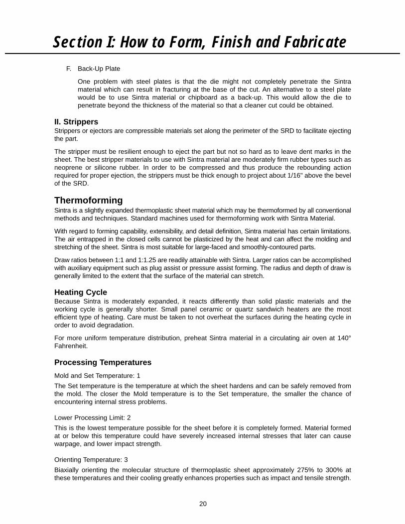
F. Back-Up Plate
One problem with steel plates is that the die might not completely penetrate the Sintramaterial which can result in fracturing at the base of the cut. An alternative to a steel platewould be to use Sintra material or chipboard as a back-up. This would allow the die topenetrate beyond the thickness of the material so that a cleaner cut could be obtained.
II. StrippersStrippers or ejectors are compressible materials set along the perimeter of the SRD to facilitate ejectingthe part.
The stripper must be resilient enough to eject the part but not so hard as to leave dent marks in thesheet. The best stripper materials to use with Sintra material are moderately firm rubber types such asneoprene or silicone rubber. In order to be compressed and thus produce the rebounding actionrequired for proper ejection, the strippers must be thick enough to project about 1/16" above the bevelof the SRD.
ThermoformingSintra is a slightly expanded thermoplastic sheet material which may be thermoformed by all conventionalmethods and techniques. Standard machines used for thermoforming work with Sintra Material.
With regard to forming capability, extensibility, and detail definition, Sintra material has certain limitations.The air entrapped in the closed cells cannot be plasticized by the heat and can affect the molding andstretching of the sheet. Sintra is most suitable for large-faced and smoothly-contoured parts.
Draw ratios between 1:1 and 1:1.25 are readily attainable with Sintra. Larger ratios can be accomplishedwith auxiliary equipment such as plug assist or pressure assist forming. The radius and depth of draw isgenerally limited to the extent that the surface of the material can stretch.
Heating CycleBecause Sintra is moderately expanded, it reacts differently than solid plastic materials and theworking cycle is generally shorter. Small panel ceramic or quartz sandwich heaters are the mostefficient type of heating. Care must be taken to not overheat the surfaces during the heating cycle inorder to avoid degradation.
For more uniform temperature distribution, preheat Sintra material in a circulating air oven at 140°Fahrenheit.
Processing Temperatures
Mold and Set Temperature: 1
The Set temperature is the temperature at which the sheet hardens and can be safely removed fromthe mold. The closer the Mold temperature is to the Set temperature, the smaller the chance ofencountering internal stress problems.
Lower Processing Limit: 2
This is the lowest temperature possible for the sheet before it is completely formed. Material formedat or below this temperature could have severely increased internal stresses that later can causewarpage, and lower impact strength.
Orienting Temperature: 3
Biaxially orienting the molecular structure of thermoplastic sheet approximately 275% to 300% atthese temperatures and their cooling greatly enhances properties such as impact and tensile strength.
Section I: How to Form, Finish and Fabricate

21
Normal Forming Temperature: 4
This is the temperature which the sheet should reach for proper forming conditions under normalcircumstances. The normal forming temperature is determined by heating the sheet to the highesttemperature at which it still has enough strength to be handled, yet below the degradation temperature.
Upper Limit: 5
The Upper Limit is the temperature at which the sheet begins to degrade or decompose. It is crucialto ensure that the sheet temperature stays below this temperature.
Section I: How to Form, Finish and Fabricate
Simples Rules to Follow When Designing Molds1. Make your part no bigger than absolutely necessary.2. Make the ratio of part height to part minimum width as small as possible.3. Make all outside radii and inside fillets as large as possible.4. Allow as much draft on all parts as possible.5. Always design to a reference point in the mold for trimming or hole placement.6. Mold in details, such as ribbing or domed surface, for adding stiffness.7. Design in details for positioning other components to be added.
Mold ConstructionWhen deciding between Male or Female molds one should take into account the following points:
1. Which side of the part needs the detail?2. Male molds are cheaper than female molds.3. Closer tolerances can be held on male molds.4. With female molds, the flange area wall thickness is the greatest while the bottom of the cavity
is the thinnest. By using a male mold, this thickness variation is just the opposite.
Additional Thermoforming TipsSintra material, provided it is stored indoors or properly sheltered, need not be dried before forming.Unlike ABS and polycarbonates, Sintra material does not absorb any hydroscopic moisture.
Plug-assist forming, using normal equipment, is necessary for more complicated shapes. Because ofthe lower heat capacity of Sintra material, low conductivity materials must be used for the plug.
Molds must be designed to facilitate ready flow of material. Sharp edges and narrow recesses shouldbe avoided. Radii should not be less than 1.5 to 2 times the original sheet thickness.
Double-sided (sandwich type) heating is strongly recommended, especially for thicker sheets, Sintramaterial of 3 mm gauge and thicker can be thermoformed only with a double-sided heating arrangement.
When heated above 150° Fahrenheit, sheets shrink slightly in the extrusion direction. Provide for thefirm clamping down of sheets or for controlled slip-in.
When thermoforming colored Sintra material, deep draws combined with sharp radii may cause stresswhitening, as with most PVC materials.
THERMOFORMING PROCESSING TEMPERATURE RANGE
1 2 3 4 5
Mold & Set Lower Orienting Normal Forming Upper LimitTemperature Processing Limit Temperature (core) Temp.
°F °C °F °C °F °C °F °C °F °C
115 46 240 116 260 127 275 135 350 177

22
Ultrasonic TechnologyUltrasonic welding is accomplished by means of non-audible sound waves.
In ultrasonic welding, vibratory energy is converted to heat through friction that melts and fuses theplastic. When the vibration stops, the plastic solidifies under pressure, producing a weld. Sintra is onlyweldable to Sintra or other Rigid PVC materials.
Essential components required to apply ultrasonic energy are:
Power supply—ultrasonic generator that supplies high-frequency electrical energy.
Converter—component that changes electrical energy to mechanical vibratory energy.
Booster Horn—increases or decreases the amplitude of vibration supplied to the horn.
Horn—tool that transmits the ultrasonic energy to the part.
The cell structure of Sintra sets certain limitations on this method of joining. If an ultrasonic process isunder consideration, companies specializing in this type of work should be consulted.
Spot Welding: Utilizing ultrasonics for spot welding is accomplished with a spot welding tip as shownin figure 1. The tip should produce a head having a diameter of three times the thickness of the toplayer. The length of the protruding tip should be one and one-half times the thickness of the top layerof material.
FIGURE 1
Ultrasonic spot welding produces one side with a cosmetic surface and the other having a hole throughthe top layer with a neat ring around the perimeter of the hole.
Insertion: The most common metal component for insertion into Sintra material would be a threadedinsert which are designed with knurls, flutes, undercuts or threads to resist loads imposed on thefinished product. The heat generated by the insert vibrating against the plastic causes the plastic tomelt, permitting the insert to be pressed into place. A sufficient amount of plastic must be displaced tofill the undercuts, knurls, flutes, or threads of the insert to lock the insert in place.
For maximum pullout and torque strengths, the top of the seated insert should be flush or slightlyabove the surface of the part as in figure 2.
FIGURE 2
Section I: How to Form, Finish and Fabricate
1.5T1.5T
3T
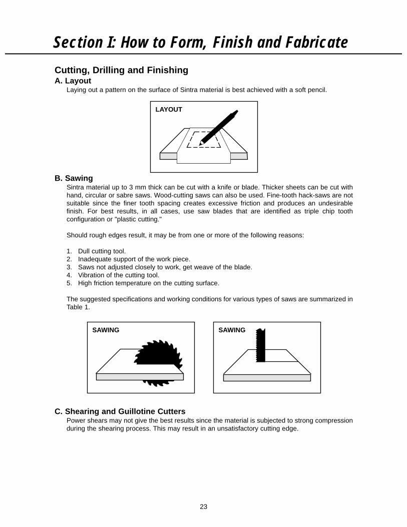
Cutting, Drilling and FinishingA. Layout
Laying out a pattern on the surface of Sintra material is best achieved with a soft pencil.
B. SawingSintra material up to 3 mm thick can be cut with a knife or blade. Thicker sheets can be cut withhand, circular or sabre saws. Wood-cutting saws can also be used. Fine-tooth hack-saws are notsuitable since the finer tooth spacing creates excessive friction and produces an undesirablefinish. For best results, in all cases, use saw blades that are identified as triple chip toothconfiguration or "plastic cutting."
Should rough edges result, it may be from one or more of the following reasons:
1. Dull cutting tool.2. Inadequate support of the work piece.3. Saws not adjusted closely to work, get weave of the blade.4. Vibration of the cutting tool.5. High friction temperature on the cutting surface.
The suggested specifications and working conditions for various types of saws are summarized inTable 1.
C. Shearing and Guillotine CuttersPower shears may not give the best results since the material is subjected to strong compressionduring the shearing process. This may result in an unsatisfactory cutting edge.
23
Section I: How to Form, Finish and Fabricate
LAYOUT
SAWINGSAWING

24
D. DrillingSintra material can be drilled with conventional, high helix, high speed steel or carbide-tipped metal bits.
Quick removal of chips can be achieved by a process of high-revolution, slow-feed and occasionallifting of the drill bit. High pressure air can be used to evacuate the immediate area from chips.
Smaller drills run at faster speeds than large drills. Pressure should be released near the terminationof through holes to prevent breakthrough.
Cutting edges must be kept sharp to prevent poor surface finish and undersized holes.
Specifications, working conditions, and suggested drill bits are summarized in Table 1.
E. RoutingStationary or hand routers can be used for slotting, beveling, rabbeting, rounding edges and trimming.Best cutting results are obtained with carbide-tipped router bits.
Routing, as a preparation for folding and heat bending, requires special shaped router bits. Thisinformation is included in "Heat Bending."
Specifications and working conditions are summarized in Table 1.
Section I: How to Form, Finish and Fabricate
ROUTINGROUTING
DRILLINGDRILLING

25
F. Industrial Laser Cutting Sintra MaterialIndustrial lasers may be used to cut or engrave Sintra material. This operation must be accomplishedwith adequate ventilation to rout the emitted smoke away from operators. Decomposition of the Sintramaterial will occur when material temperatures exceed 350° Fahrenheit. As described in the MaterialSafety Data Sheet for Sintra material, the product will burn in the presence of supported combustion, andemit hydrogen chloride gas, benzene, water, carbon monoxide, carbon dioxide, and smoke. The cut edgeof the material may char, unlike acrylic plastics which glaze when exposed to intense heat. Edgeconditions and cutter feed speed will be dependent upon the type of laser used and the gauge of cut.
G. MillingSintra material can be machined on the usual types of milling machines—universal, horizontal andvertical. To avoid indenting the surface when clamping, place flat pieces of wood or plastic betweenthe work and the clamps.
Tool geometry and working conditions are summarized in Table 1.
H. Edge FinishingSmooth edges can be achieved with a file, plane or sander. Conventional tools and methods forworking wood or plastics can be utilized. Edges can be polished with solvent. More information on thistopic is in the painting section.
I. Surface FinishingSurface finishing with cutting tools is possible. Grinding or polishing is not recommended since thismay damage the surface and expose cut cells.
Short bursts of hot air from a heat gun can be used to remove small surface scratches and small dents.
Section I: How to Form, Finish and Fabricate

26
Section I: How to Form, Finish and Fabricate
CUTTINGDRILLING & WHERE USED, RECOMMENDED RECOMMENDED RECOMMENDEDROUTING ADVANTAGES/ BLADE/BIT WORKING BLADE/BITMETHODS DISADVANTAGES GEOMETRY CONDITIONS
Circular saws Used for making cuts on Angled or curved Cutting speed: 1. No-meltradial arm or panel saws. teeth with alter- up to 10,000 FPM. Plasti-Kerf.Can stack up sheets if native chamfer Feed: upmore than one piece is cutting nippers or to 100 FPM. 2. Triple-chiprequired at same length. set. Must be CarbideEdge finishing may be carbide-tipped. blade.needed since open cells Well-roundedare exposed by cut. spaces between 3. Many veneer
teeth. Rake angle: type blades.5°-10°. Freeangle: 10°-20°.Distance betweenteeth 3/16"-1/2".
Band saws Used for making curved No-rake, 8 teeth 3,000 SFM. Do-All straightcuts. Get very smooth per inch. Hard knife edge or "V"edge—very little additional edge type. tooth blade.edge finishing required.
Sabre saws Portable. Good for cutting 10-15 teeth per 2-pack bladecurves, bevels, and inch. Hard edge package fromintricate patterns. Not type. Central Plasticsgood for straight cut. Distributors.
Use their greenblade for Sintramaterial.
Drilling For all holes up to 1" Carbide-tipped, Cutting speed: 1. Do-All D-175Bdiameter. Larger holes can high helix 150-1,000 FPM high helix.be cut with a hole saw. preferred. Angle (defined as RPM
at tip: 100°-110°. x circumference 2. Plasdrills.Pitch angle: 30°. of bit; smaller
diameter runsfaster). Feed rate:.001-.010 in./rev.(rate should bedecreased asdepth increases).
Routing Used particularly for High-speed Cutting speed: Most high-speedmaking slots prior to heat carbide router 3,000 FRM. Feed carbide bits,bending. Can be stationery bits. Various rate: 10 in./min. available ator portable, depending on cutter head hardware stores.type of operation desired. configurations.
Milling Rake angle: Cutting speed:5°-20°. 3,000-3,300 FPM.Free angle: Feed rate:10°-25°. 8"-20"/min.
TABLE I — SPECIFICATIONS AND WORKING CONDITIONS CHART

27
Section II: Attachment and Fastening
Basic CommentsIn the mounting or installation of Sintra material in outdoor applications or in rooms with very drastictemperature changes, the linear thermal expansion of the material has to be taken into consideration.As in all plastic materials, the sheets can warp, bulge, or inadmissible stress conditions can occur.
The linear thermal expansion of Sintra material is about the same magnitude as that of solid plasticmaterials, and is clearly larger than those of metals, wood and inorganic building materials likebrickwork and concrete.
The dimensional change in each case depends on the expected difference between minimum andmaximum temperature and the length and width of the sheet to be mounted. Appropriate values areshown in Figure 1.
TOTAL TEMPERATURECHANGE (°F) 48 INCHES 60 INCHES 96 INCHES 120 INCHES
20 .032 .040 .064 .07940 .064 .079 .127 .15860 .095 .119 .190 .23880 .127 .158 .253 .317
100 .158 .198 .317 .396120 .190 .238 .380 .475140 .222 .277 .444 .554
FIGURE 1EXPANSION/CONTRACTION (INCHES) VS.TEMPERATURE CHANGE FOR COMMON SHEET SIZES:
DISTANCES BETWEEN FASTENING POINTSFOR SCREW AND RIVET JOINTS
SHEET SIZE DISTANCE BETWEENFASTENING
2 mm 6 – 8 in.3 mm 12 – 16 in.4 mm 20 – 28 in.5 mm 31 – 43 in.6 mm 47 – 70 in.
Temperature FluctuationsFor the United States surface temperature differences of 100°-180° Fahrenheit between extremes(winter -30° Fahrenheit, summer +150° Fahrenheit) must be assumed in exterior usage. Dark coloredsheets heat up more than light colors, if exposed to direct sunlight.

28
EXAMPLE:
A printed sign board made of 3 mm strong, white Sintra material, measuring 39 in. x 98 in. is to befastened to a wooden framework with screws of .196 in. shaft diameter. The sign is to be erectedoutdoors in a well protected and shaded place. What is the thermal expansion to be considered inmounting this sign board?
Minimum temperature (winter) 5° Fahrenheit
Maximum temperature (summer) 95° Fahrenheit
Temperature difference 90° Fahrenheit
Clearance D-d from Figure 2 (wood)for 79 in. sheet length .273 in.
for 98 in. length
98 in. x .273 in. = .338 in.79 in.
for 39 in. width
39 in. x .273 in. = .135 in.79 in.
SOLUTION: HOLES
Holes diameter = Clearance + bolt shank diameter= .338 in. + .196 in. = .534 in.
Diameter of holes to be drilled into the Sintra material sheet: 9/16 in. (.534 in.)
SOLUTION: SLOTS
Length (a)= Clearance over sheet length + bolt shank diameter= .338 + .196 = .534 in. (9/16 in.)
Width (b) = Clearance over sheet width + bolt shank diameter= .135 + .196 = .331 in. (3/8 in.)
For sheets of more than 79 inches in length, slots are preferable. They permit the usage of smallerwashers (discs).
Section II: Attachment and Fastening
A
B

THERMAL EXPANSION IN INCHES
MATERIAL LENGTH WIDTH
Cellulose acetate CA .497 .249
Polyethylene LD PE .621 .312
Polyethylene HD PE .466 .234
Polyamide 6 PA 6 .261 .132
Polyamide 12 PA 12 .280 .140
Polycarbonate PC .199 .101
Polymethylmethacrylate PMMA .236 .117
Polypropylene PP .435 .218
Polystyrene PS .217 .109
Polystyrene SAN .249 .125
Polystyrene ABS .249 .125
Polyvinylchloride PVC .317 .158
Sintra Material (700 Density) .317 .158
Wood .019 .008
Aluminum .126 .063
Steel .031 .016
Concrete .037 .016
29
Section II: Attachment and FasteningCOMPARISON OF THE THERMAL EXPANSION OF VARIOUS PLASTICS AND OTHERCONSTRUCTION MATERIALS (96 IN. SHEET LENGTH) FOR A TEMPERATURE INCREASE OF100° FAHRENHEIT.
FIGURE 3
L=96 IN. L
W=4
8 IN
.
W
30
Exterior SignsSintra Material used correctly and with basic mechanical fixing methods is suitable for exterior use.The following tips have been compiled to be used as a general guide for fixing Sintra Material for aminimum amount of breakage. Using Sintra Material can provide an excellent weatherproof signsubstrate ready for screen printing, painting, or vinyl graphics.
Tips on Sign Installation With PostThe following data has been compiled as a general guide for the mounting of Sintra Material. Unusualdesigns falling outside the examples given may require certain modifications when considering SintraMaterial.
Major Items to be Considered
1. Bolt holes should always be larger than the bolt shaft to allow for thermal expansion andcontraction, thus eliminating the possible stress at bolt fixing points. The use of washers spreadthe compressive load when bolts/nuts are tightened. Never over-tighten—this will only weaken theconnection.
2. Split timber posts are the best to use because the Sintra Material is supported evenly onboth sides. If steel or aluminum poles are used, nylon bolts and washers give the best results. Inall cases, never skimp on the number of fixing points. Use at least three on the average-sized sign.They should be evenly spaced and away from the top and bottom edges.
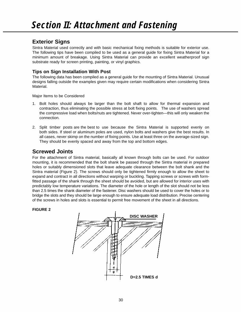
Screwed JointsFor the attachment of Sintra material, basically all known through bolts can be used. For outdoormounting, it is recommended that the bolt shank be passed through the Sintra material in preparedholes or suitably dimensioned slots that leave adequate clearance between the bolt shank and theSintra material (Figure 2). The screws should only be tightened firmly enough to allow the sheet toexpand and contract in all directions without warping or buckling. Tapping screws or screws with form-fitted passage of the shank through the sheet should be avoided, but are allowed for interior uses withpredictably low temperature variations. The diameter of the hole or length of the slot should not be lessthan 2.5 times the shank diameter of the fastener. Disc washers should be used to cover the holes or tobridge the slots and they should be large enough to ensure adequate load distribution. Precise centeringof the screws in holes and slots is essential to permit free movement of the sheet in all directions.
FIGURE 2
Section II: Attachment and Fastening
D=2.5 TIMES d
DISC WASHER

31
Section II: Attachment and Fastening
Riveted JointsThe measures that are used for screwed joints also apply to riveted joints. For this reason full rivets,whose shaft enlarges during the clenching operation so that the clearance to the hole diameterdiminishes, are not suitable for outdoor mounting of Sintra material. Blind rivets (pop rivets) aresuitable for fastening Sintra material to metal bases which are mounted by the drawing of aluminumor the steel mandrel.
Frame Fastening of Flat Sintra Material SheetsBesides the inherent rigidity of Sintra material sheets, which is dependent on thickness, all possibleexterior stresses, e.g., wind pressure, etc., must be taken into consideration in frame fastening. Forappropriate mechanical and elastic property values the data sheet should be consulted. Dimensionalchanges due to thermal expansion (or contraction) must be taken into consideration by leavingsufficient clearance between the sheet edge and the frame. Relative thermal expansion values forvarious frame materials can be taken from Figure 3.
These are suspended attachment frames. Leavea space in the lower section, as well as in the sidesections to allow for Sintra expansion. One pin inthe middle of the rail can keep the Sintra centeredin the frame.
Grain DirectionSintra Material is an extruded P.V.C. product and a directional grain is seen along the length of thesheet. Because Sintra Material has a greater flexural strength along the extrusion direction, it is alwaysadvisable to cut signs so that the grain direction is horizontal to the post or pole fixings. This will allowSintra Material to "flex" with the wind pressure and ensure the best performance.
RIGHT
GRAIN DIRECTION
WRONG
GR
AIN
D
IRE
CTI
ON
32
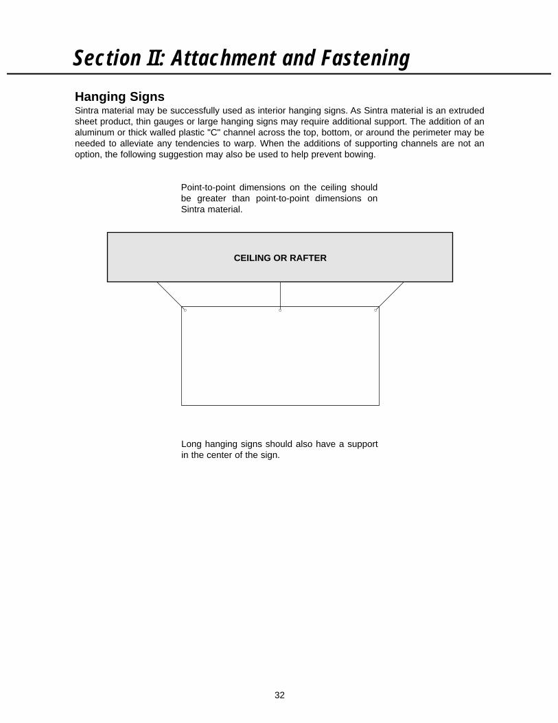
Hanging SignsSintra material may be successfully used as interior hanging signs. As Sintra material is an extrudedsheet product, thin gauges or large hanging signs may require additional support. The addition of analuminum or thick walled plastic "C" channel across the top, bottom, or around the perimeter may beneeded to alleviate any tendencies to warp. When the additions of supporting channels are not anoption, the following suggestion may also be used to help prevent bowing.
Section II: Attachment and Fastening
Point-to-point dimensions on the ceiling shouldbe greater than point-to-point dimensions onSintra material.
Long hanging signs should also have a supportin the center of the sign.
CEILING OR RAFTER
33
Section II: Attachment and Fastening
Concealed Fastening On Brickwork of Cut-OutAdvertising Letters and Figures Made Out of Sintra MaterialThe system described here is a method of concealed fastening, not visible to the observing public. Forthe sake of aesthetics, a certain distance between the type print and the backing wall is often desired,whereby the system is ideally suited. The mounting is quick, easy and inexpensive.
The system consists of square mounting plates constructed out of Sintra material with an encased pinor special nail for brickwork.
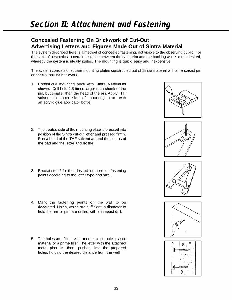
1. Construct a mounting plate with Sintra Material asshown. Drill hole 2.5 times larger than shank of thepin, but smaller than the head of the pin. Apply THFsolvent to upper side of mounting plate withan acrylic glue applicator bottle.
2. The treated side of the mounting plate is pressed intoposition of the Sintra cut-out letter and pressed firmly.Run a bead of the THF solvent around the seams ofthe pad and the letter and let the
3. Repeat step 2 for the desired number of fasteningpoints according to the letter type and size.
4. Mark the fastening points on the wall to bedecorated. Holes, which are sufficient in diameter tohold the nail or pin, are drilled with an impact drill.
5. The holes are filled with mortar, a curable plasticmaterial or a prime filler. The letter with the attachedmetal pins is then pushed into the preparedholes, holding the desired distance from the wall.
34
Section III: Engineering/Specifications
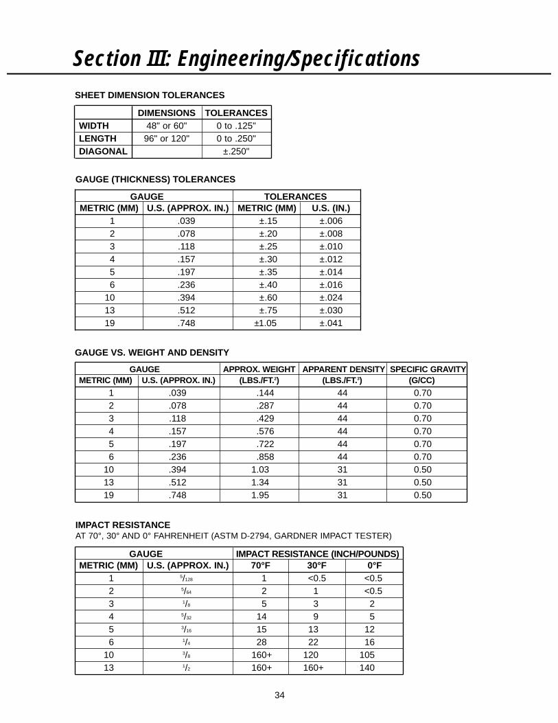
GAUGE APPROX. WEIGHT APPARENT DENSITY SPECIFIC GRAVITYMETRIC (MM) U.S. (APPROX. IN.) (LBS./FT.2) (LBS./FT.3) (G/CC)
1 .039 .144 44 0.702 .078 .287 44 0.703 .118 .429 44 0.704 .157 .576 44 0.705 .197 .722 44 0.706 .236 .858 44 0.70
10 .394 1.03 31 0.5013 .512 1.34 31 0.5019 .748 1.95 31 0.50
SHEET DIMENSION TOLERANCES
DIMENSIONS TOLERANCESWIDTH 48" or 60" 0 to .125"LENGTH 96" or 120" 0 to .250"DIAGONAL ±.250"
GAUGE TOLERANCESMETRIC (MM) U.S. (APPROX. IN.) METRIC (MM) U.S. (IN.)
1 .039 ±.15 ±.0062 .078 ±.20 ±.0083 .118 ±.25 ±.0104 .157 ±.30 ±.0125 .197 ±.35 ±.0146 .236 ±.40 ±.016
10 .394 ±.60 ±.02413 .512 ±.75 ±.03019 .748 ±1.05 ±.041
GAUGE (THICKNESS) TOLERANCES
GAUGE IMPACT RESISTANCE (INCH/POUNDS)METRIC (MM) U.S. (APPROX. IN.) 70°F 30°F 0°F
1 5/128 1 <0.5 <0.52 5/64 2 1 <0.53 1/8 5 3 24 5/32 14 9 55 3/16 15 13 126 1/4 28 22 16
10 3/8 160+ 120 10513 1/2 160+ 160+ 140
IMPACT RESISTANCEAT 70°, 30° AND 0° FAHRENHEIT (ASTM D-2794, GARDNER IMPACT TESTER)
GAUGE VS. WEIGHT AND DENSITY
35
Section III: Engineering/Specifications
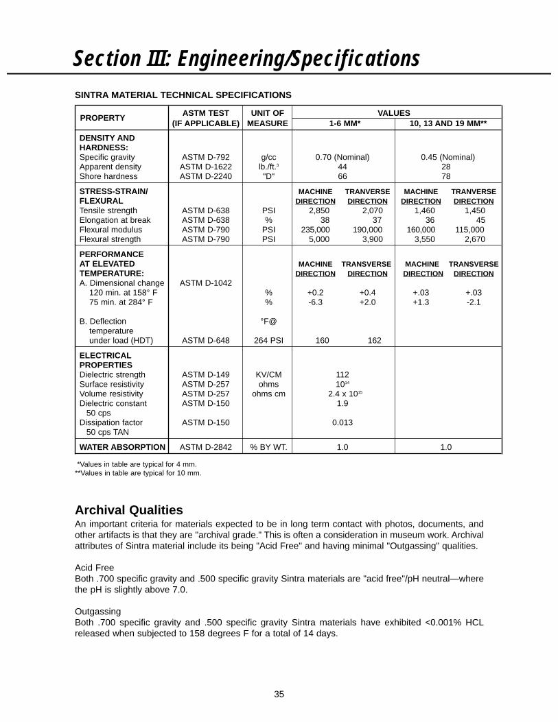
Archival QualitiesAn important criteria for materials expected to be in long term contact with photos, documents, andother artifacts is that they are "archival grade." This is often a consideration in museum work. Archivalattributes of Sintra material include its being "Acid Free" and having minimal "Outgassing" qualities.
Acid FreeBoth .700 specific gravity and .500 specific gravity Sintra materials are "acid free"/pH neutral—wherethe pH is slightly above 7.0.
OutgassingBoth .700 specific gravity and .500 specific gravity Sintra materials have exhibited <0.001% HCLreleased when subjected to 158 degrees F for a total of 14 days.
*Values in table are typical for 4 mm.**Values in table are typical for 10 mm.
ASTM TEST UNIT OF VALUESPROPERTY(IF APPLICABLE) MEASURE 1-6 MM* 10, 13 AND 19 MM**
DENSITY ANDHARDNESS:Specific gravity ASTM D-792 g/cc 0.70 (Nominal) 0.45 (Nominal)Apparent density ASTM D-1622 lb./ft.3 44 28Shore hardness ASTM D-2240 "D" 66 78
STRESS-STRAIN/ MACHINE TRANVERSE MACHINE TRANVERSEFLEXURAL DIRECTION DIRECTION DIRECTION DIRECTIONTensile strength ASTM D-638 PSI 2,850 2,070 1,460 1,450Elongation at break ASTM D-638 % 38 37 36 45Flexural modulus ASTM D-790 PSI 235,000 190,000 160,000 115,000Flexural strength ASTM D-790 PSI 5,000 3,900 3,550 2,670
PERFORMANCEAT ELEVATED MACHINE TRANSVERSE MACHINE TRANSVERSETEMPERATURE: DIRECTION DIRECTION DIRECTION DIRECTIONA. Dimensional change ASTM D-1042
120 min. at 158° F % +0.2 +0.4 +.03 +.0375 min. at 284° F % -6.3 +2.0 +1.3 -2.1
B. Deflection °F@temperatureunder load (HDT) ASTM D-648 264 PSI 160 162
ELECTRICALPROPERTIESDielectric strength ASTM D-149 KV/CM 112Surface resistivity ASTM D-257 ohms 1014
Volume resistivity ASTM D-257 ohms cm 2.4 x 10¹⁵
Dielectric constant ASTM D-150 1.950 cps
Dissipation factor ASTM D-150 0.01350 cps TAN
WATER ABSORPTION ASTM D-2842 % BY WT. 1.0 1.0
SINTRA MATERIAL TECHNICAL SPECIFICATIONS
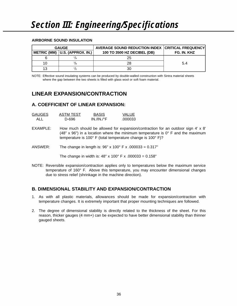
36
LINEAR EXPANSION/CONTRACTION
A. COEFFICIENT OF LINEAR EXPANSION:
GAUGES ASTM TEST BASIS VALUEALL D-696 IN./IN./°F .000033
EXAMPLE: How much should be allowed for expansion/contraction for an outdoor sign 4' x 8'(48" x 96") in a location where the minimum temperature is 0° F and the maximumtemperature is 100° F (total temperature change is 100° F)?
ANSWER: The change in length is: 96" x 100° F x .000033 = 0.317"
The change in width is: 48" x 100° F x .000033 = 0.158"
NOTE: Reversible expansion/contraction applies only to temperatures below the maximum servicetemperature of 160° F. Above this temperature, you may encounter dimensional changesdue to stress relief (shrinkage in the machine direction).
B. DIMENSIONAL STABILITY AND EXPANSION/CONTRACTION
1. As with all plastic materials, allowances should be made for expansion/contraction withtemperature changes. It is extremely important that proper mounting techniques are followed.
2. The degree of dimensional stability is directly related to the thickness of the sheet. For thisreason, thicker gauges (4 mm+) can be expected to have better dimensional stability than thinnergauged sheets.
Section III: Engineering/Specifications
GAUGE AVERAGE SOUND REDUCTION INDEX CRITICAL FREQUENCYMETRIC (MM) U.S. (APPROX. IN.) 100 TO 3500 HZ DECIBEL (DB) FG. IN. KHZ
6 1/4 2510 3/8 28 5.413 1/2 30
AIRBORNE SOUND INSULATION
NOTE: Effective sound insulating systems can be produced by double-walled construction with Sintra material sheets where the gap between the two sheets is filled with glass wool or soft foam material.

37
Section III: Engineering/Specifications
LOAD CAPACITYMaximum span of 4' wide sheet determined when center of sheet deflects less than 1/2" as load isapplied at center. Sheet is supported at 1/4" width around perimeter.
THERMAL INSULATING PROPERTIES
A. THERMAL CONDUCTIVITY:1–6 MM 10 MM 13 MM 19 MM
BTU = .52 .52 .456 .36
FT.2hr°F/IN.
GAUGEMETRIC (MM) U.S. (APPROX. IN.) “R” VALUES
1 5/128 .072 5/64 .143 1/8 .214 5/32 .285 3/16 .356 1/4 .42
10 3/8 .7213 1/2 1.1019 3/4 2.08
GAUGE MAXIMUM SPAN (INCHES)METRIC (MM) U.S. (APPROX. IN.) NO LOAD 10 LBS. 20 LBS. 30 LBS.
1 5/128 24 <242 5/64 30 <243 1/8 36 <244 5/32 40 <245 3/16 54 24 <246 1/4 60 36 24
10 3/8 96 60 4813 1/2 96+ 96+ 96 60
NOTE: The assumption is that the whole weight is applied at the center. If the weight wasdistributed over the area of the sheet, a longer span could be used to support thesame weight.
EXAMPLE: What are the options in building a shelf to support 20 lbs.?
1. If we choose not to space supports closer than 2' (24") apart, the minimumthickness which could support this weight would be a 6 mm sheet. It would take threecenter supports for a 4' x 8' sheet.
2. If we choose a 10 mm sheet, we could place the supports 48" apart (roughly onecenter support for a 4' x 8' sheet).
3. If we choose a 13 mm sheet, we could use the whole 4' x 8' sheet without anycenter supports.
B. “R” VALUES

38
Resistance to Standard ReagentsGeneralizations:
Mineral Acids Resistant to most (check resistance to specific acids)Bases ResistantSalts ResistantAlcohols ResistantParaffinic Hydrocarbons ResistantOils and Greases ResistantChlorinated Hydrocarbons Not resistantAromatic Hydrocarbons Not resistantEsters Not resistantKetones Not resistant
Resistance to certain other fluid mixtures such as fuel oils with moderate aromatic content cannot bedetermined on the basis of immersion testing alone. Actual use data must be obtained.
It should be noted that in addition to temperature and reagent concentration, other factors such asstress level can also affect the chemical resistance of Sintra material. Because of this, the finaldetermination of suitability must often depend on some in-service testing.
CODE:1–Resistant 2–Limited Resistance 3–Little Resistance 4–Not Resistant(Chemical resistance of Sintra material at an ambient temperature to standard reagents accordingto ASTM D-543)
Acetic acid Dimethyl formamide . . . . . . . . . . . . . . . . . 4glacial . . . . . . . . . . . . . . . . . . . . . . . . . . 2 Distilled water . . . . . . . . . . . . . . . . . . . . . . 15% . . . . . . . . . . . . . . . . . . . . . . . . . . . . . 1 Ethyl acetate . . . . . . . . . . . . . . . . . . . . . . . 4
Acetone . . . . . . . . . . . . . . . . . . . . . . . . . . 4 Ethyl alcohol:Ammonium hydroxide: 95% . . . . . . . . . . . . . . . . . . . . . . . . . . . 1
conc. . . . . . . . . . . . . . . . . . . . . . . . . . . . 1 50% . . . . . . . . . . . . . . . . . . . . . . . . . . . . 110% . . . . . . . . . . . . . . . . . . . . . . . . . . . . 1 2-ethylhexyl sebacate . . . . . . . . . . . . . . . . 4
Aniline . . . . . . . . . . . . . . . . . . . . . . . . . . . . 4 Heptane . . . . . . . . . . . . . . . . . . . . . . . . . . 1Benzene . . . . . . . . . . . . . . . . . . . . . . . . . . 4 Hydrochloric acid:Carbon tetrachloride . . . . . . . . . . . . . . . . . 3 conc. . . . . . . . . . . . . . . . . . . . . . . . . . . . 1Chromic acid 10% . . . . . . . . . . . . . . . . . . . 1 10% . . . . . . . . . . . . . . . . . . . . . . . . . . . . 1Citric acid 10% . . . . . . . . . . . . . . . . . . . . . 1 Hydrofluoric acid 40% . . . . . . . . . . . . . . . . 1Cottonseed oil . . . . . . . . . . . . . . . . . . . . . . 1 Hydrogen peroxide:Detergent solution 0.025% . . . . . . . . . . . . 1 28% . . . . . . . . . . . . . . . . . . . . . . . . . . . . 1Diethyl ether . . . . . . . . . . . . . . . . . . . . . . . 1 3% . . . . . . . . . . . . . . . . . . . . . . . . . . . . . 1
Section IV: Chemical Resistance
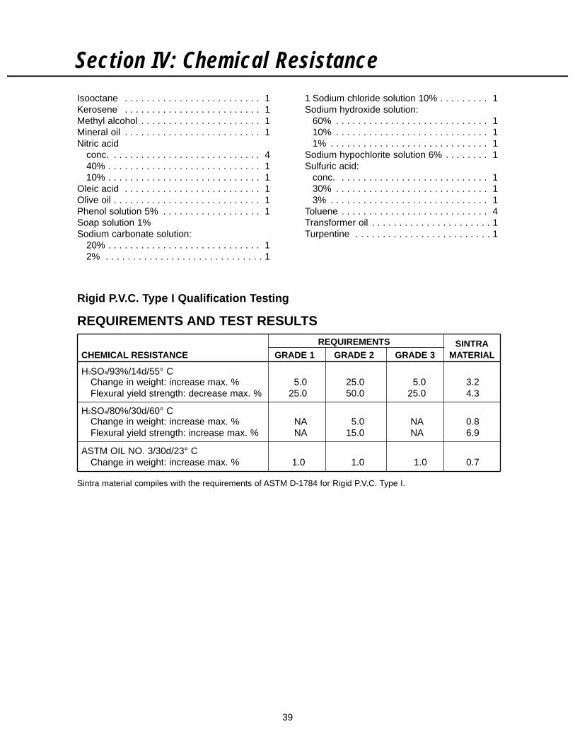
39
Section IV: Chemical ResistanceIsooctane . . . . . . . . . . . . . . . . . . . . . . . . . 1 1 Sodium chloride solution 10% . . . . . . . . . 1Kerosene . . . . . . . . . . . . . . . . . . . . . . . . . 1 Sodium hydroxide solution:Methyl alcohol . . . . . . . . . . . . . . . . . . . . . . 1 60% . . . . . . . . . . . . . . . . . . . . . . . . . . . . 1Mineral oil . . . . . . . . . . . . . . . . . . . . . . . . . 1 10% . . . . . . . . . . . . . . . . . . . . . . . . . . . . 1Nitric acid 1% . . . . . . . . . . . . . . . . . . . . . . . . . . . . . 1
conc. . . . . . . . . . . . . . . . . . . . . . . . . . . . 4 Sodium hypochlorite solution 6% . . . . . . . . 140% . . . . . . . . . . . . . . . . . . . . . . . . . . . . 1 Sulfuric acid:10% . . . . . . . . . . . . . . . . . . . . . . . . . . . . 1 conc. . . . . . . . . . . . . . . . . . . . . . . . . . . . 1
Oleic acid . . . . . . . . . . . . . . . . . . . . . . . . . 1 30% . . . . . . . . . . . . . . . . . . . . . . . . . . . . 1Olive oil . . . . . . . . . . . . . . . . . . . . . . . . . . . 1 3% . . . . . . . . . . . . . . . . . . . . . . . . . . . . . 1Phenol solution 5% . . . . . . . . . . . . . . . . . . 1 Toluene . . . . . . . . . . . . . . . . . . . . . . . . . . . 4Soap solution 1% Transformer oil . . . . . . . . . . . . . . . . . . . . . . 1Sodium carbonate solution: Turpentine . . . . . . . . . . . . . . . . . . . . . . . . . 1
20% . . . . . . . . . . . . . . . . . . . . . . . . . . . . 12% . . . . . . . . . . . . . . . . . . . . . . . . . . . . . 1
REQUIREMENTS SINTRACHEMICAL RESISTANCE GRADE 1 GRADE 2 GRADE 3 MATERIAL
H2SO4/93%/14d/55° CChange in weight: increase max. % 5.0 25.0 5.0 3.2Flexural yield strength: decrease max. % 25.0 50.0 25.0 4.3
H2SO4/80%/30d/60° CChange in weight: increase max. % NA 5.0 NA 0.8Flexural yield strength: increase max. % NA 15.0 NA 6.9
ASTM OIL NO. 3/30d/23° CChange in weight: increase max. % 1.0 1.0 1.0 0.7
Rigid P.V.C. Type I Qualification Testing
Sintra material compiles with the requirements of ASTM D-1784 for Rigid P.V.C. Type I.
REQUIREMENTS AND TEST RESULTS
40
General CommentsField performance over a 2–4 year period shows good weatherability in outdoor applications currentlyin operation in various environmental conditions. Reliable predictions, however, can only be made onthe strength of long-term outdoor ("real-time") weathering. Such testing is currently in progress atvarious geographical locations.
Outdoor Mounting of Sintra MaterialThe effects of outdoor exposure on tensile, color, impact resistance and dimensional stability are asfollows:
A. TensileThe effects of medium altitude outdoor exposure with a comparatively high U.V. level on Sintramaterial during 24 months show virtually no change in tensile strength.
B. Color ChangesField testing reported by many Sintra material customers shows acceptable color maintenanceusing white material. In general, white has been found to have superior weatherability overcolors. Black Sintra also has had success outdoors. Other colors are not recommended for longterm exterior usage.
Colored Sintra materials are produced with organic pigments. Exterior light and some interior lightfixtures emit light waves in the lower range of the light spectrum. These low range light waves maycause a fading of the Sintra material colors over time.
Sintra material exterior color fastness may be improved when used with some PVC compatible UVresistant, non-yellowing inks, clear top coat paints or clear laminates. (See Table III on page 6.) Inaddition to coatings and films, many light fixture manufacturers produce UV filtering diffusers thatmay also reduce or minimize these color changes for interior use.
Sintra Material is a P.V.C., therefore it will experience "browning out" or fading over time. Thisphenomenon is significantly less in white. While Sintra Material has been used in a variety ofexterior applications, the degree of generic P.V.C. "bowing out" cannot be predicted in advance ofa specific application. Therefore no guarantee on color fastness can be made.
C. Impact Resistance and Environmental Stress1. Effect of Temperature—With decreasing temperature, there is a tendency towards decreased
impact resistance. However, measurement of the cold crack temperature with a bendingapparatus for sheets of 2 mm and 3 mm thickness and a 1/2" mandrel show that undernormal winter conditions, no immediate serious embrittlement is to be expected. A 2 mm, whiteSintra material sheet can be bent around a 1/2" mandrel for 180° at an ambient temperatureof -15° C (5° F) without fracture.
2. Effect of Chemicals—Certain solvents (such as cyclohexanone) present in inks can causeenvironmental stress, cracking, and poor impact resistance. For this reason, the solventsystems used to dilute screen printing inks must be carefully chosen.
Section V: Weatherability
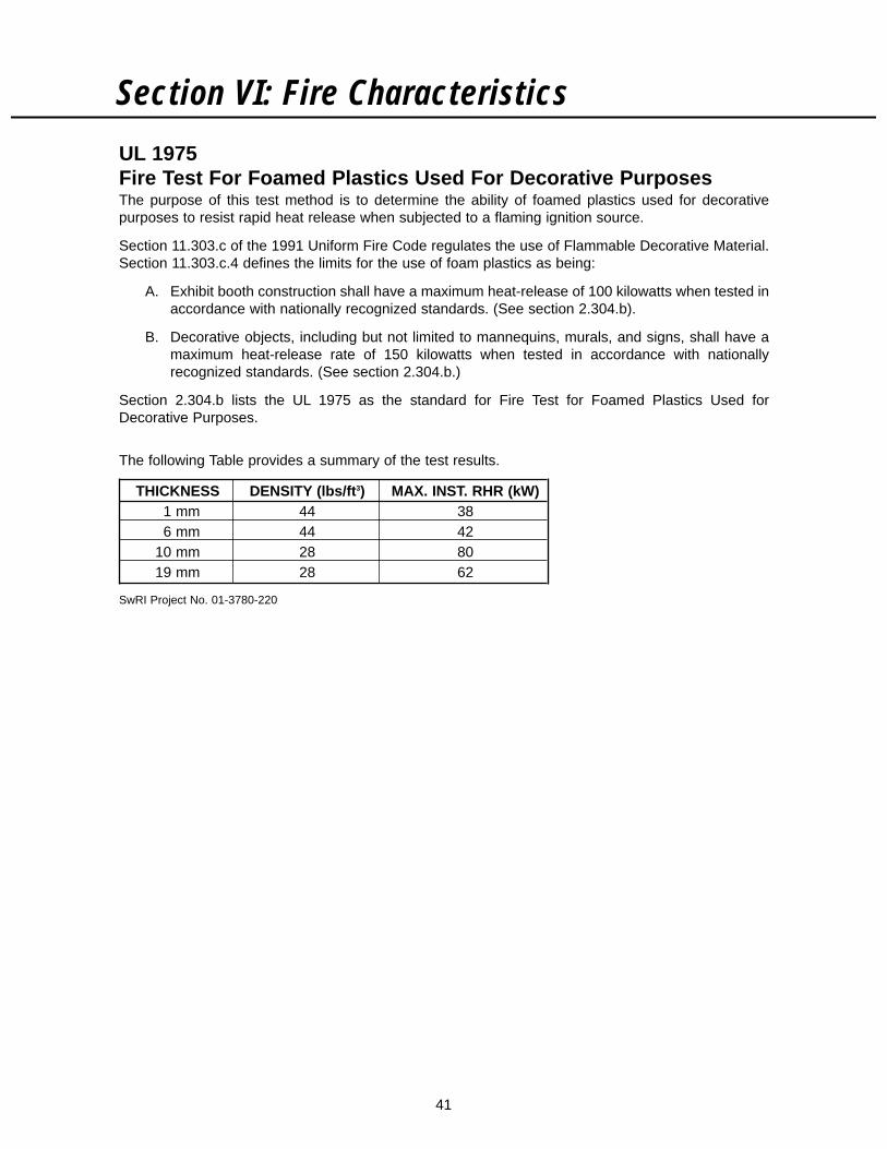
41
Section VI: Fire Characteristics
UL 1975Fire Test For Foamed Plastics Used For Decorative PurposesThe purpose of this test method is to determine the ability of foamed plastics used for decorativepurposes to resist rapid heat release when subjected to a flaming ignition source.
Section 11.303.c of the 1991 Uniform Fire Code regulates the use of Flammable Decorative Material.Section 11.303.c.4 defines the limits for the use of foam plastics as being:
A. Exhibit booth construction shall have a maximum heat-release of 100 kilowatts when tested inaccordance with nationally recognized standards. (See section 2.304.b).
B. Decorative objects, including but not limited to mannequins, murals, and signs, shall have amaximum heat-release rate of 150 kilowatts when tested in accordance with nationallyrecognized standards. (See section 2.304.b.)
Section 2.304.b lists the UL 1975 as the standard for Fire Test for Foamed Plastics Used forDecorative Purposes.
The following Table provides a summary of the test results.
THICKNESS DENSITY (lbs/ft3) MAX. INST. RHR (kW)1 mm 44 386 mm 44 42
10 mm 28 8019 mm 28 62
SwRI Project No. 01-3780-220

42
Section VI: Fire Characteristics
TEST UL 94V-0 UL 94-5V ASTM E-84TEST 5"x1/2" bar mounted vertically. Vertical test like 94V-O, except Test also called UL Steiner Tunnel Test.DESCRIPTION Flame applied to each of five more severe. Length of burner 20"–24" wide by 24' long sample fits
specimens. Two consecutive flame increased, and flame applied under roof of 25' long tunnel forming10 second burns on each at 20° to one of the bottom corners ceiling of tunnel. Gas Burners at onespecimen. of the bar. Flame applied to each end impinge flame on 7 square feet of
specimen five times at 5 second specimen. Rate of progression of flameintervals, each burn lasting observed as it passes side windows—5 seconds. decrease of light measured by photom-
eter. Flame progression plotted asdistance (of windows vs. time when flame passes window). Photometerdata plotted as percent of absorptionvs. time. Ratios of areas under curve to those of red oak, tested similarlyand calculated. Red oak has a flame spread index of 100 and a smoke developed index of 100.
CRITERIA A. No burning up to 94-5VA Criteriaspecimen clamp. A. Not have any bar specimens No dripping. that burn with flaming or glowing
combustion for more than 60B. 10 seconds max. time of seconds after the fifth flame.
flaming after each burn.B. Not have any bar specimens
C. 50 seconds max. total that drip flaming particles that time of flaming for all ignite dry absorbent surgical burns of 5 specimens. cotton located 12 inches below
the test specimen.D. 30 seconds max. time of
glowing after last burn of C. Not have any plaque specimens specimen. that exhibit a burn through (hole).
E. Repeat (A) to (D) after 94-5VB Criteriaconditioning 168H A. Not have any bar specimens at 70° C. that burn with flaming or glowing
combustion for more than 60seconds after the fifth flame.
B. Not have any bar specimens that drip flaming particles that ignite dry absorbent surgical cotton located 12 inches below the test specimen.
C. Permit a burn through (hole) onplaque specimens.
SINTRA MATERIAL SINTRA MATERIAL PERFORMANCEPERFORMANCE VS. UL 94 FLAMMABILITY VS. ABOVE CRITERIA:ABOVE CRITERIA: CLASSIFICATION
A B C D E FLAME SPREAD SMOKE DEV.1 mm White Pass 94-5VB2 mm White Pass 94-5VA2 mm Grey Pass 94-5VA 20 3803 mm all colors Pass 94-5VA 20 3154 mm Pass 94-5VA 20 4255 mm Pass 94-5VA 20 >4506 mm all colors Pass 94-5VA 20 >45010 mm White Pass 94-5VA 25 >45013 mm White Pass 94-5VA >25 >45019 mm White Pass 94-5VA >25 >450
FIRE TEST RESULTS

43
Section VI: Fire Characteristics
Relative Flammability Comparisons to Other MaterialsIn addition to its unique balance of performance properties, Sintra material has the followingadvantages as fire-retardant material:
1. Self extinguishing—remove the flame and the burning stops.
2. Relatively high ignition resistance—the heat content of Sintra material is 8,600 BTU/LB. Heatproduced by a flame from Sintra material is not enough to produce those necessary vaporswhich combine with atmospheric oxygen to create a combustible mixture. Because of its lowheat of combustion, Sintra material will not support combustion.
3. High oxygen index—ASTM D-2863 measures the percent of oxygen in an oxygen/nitrogenmixture which barely supports burning. The oxygen content of the earth’s atmosphere is about21%. Materials with oxygen index values of approximately 26 and above should not continueburning after the flame source is removed, because the normal atmospheric oxygen contentis insufficient to support combustion.
The oxygen index values of Sintra material is 46–49%. Many other plastics and naturalproducts have values under 26, as this title indicates.
LIMITING OXYGEN INDICES (LOI) OF PLYMERS(A LOW LOI VALUE INDICATES HIGH FLAMMABILITY)
BELOW 22 22–28 ABOVE 28(MATERIAL BURNS BY ITSELF) (MAY BURN UPWARDS) (MATERIAL WILL NOT
BURN BY ITSELF)
Polyacetal . . . . . . . . . . . . . . . . .15 Red Oak . . . . . . . . . . . . . . . . . . .23 Polysulfone . . . . . . . . . . . . . . .30-50Cotton . . . . . . . . . . . . . . . . . .16-17 Polyvinyl fluoride . . . . . . . . . . . . .23 Polyimides . . . . . . . . . . . . . . .31-45Polymethylmethacrylate . . . . . . .17 Polyphenylene oxide . . . . . . . . . .24 Polyphenylene sulfide . . . . . . . . .40Polyethylene . . . . . . . . . . . . . . .17 Nylon 6/6 . . . . . . . . . . . . . . . . . . .24 Rigid polyvinyl chloride . . . . . .40-49Polypropylene . . . . . . . . . . . . . .18 Polycarbonate . . . . . . . . . . . . . . .25 Sintra® material . . . . . . . . . . . .46-49Polystyrene . . . . . . . . . . . . . . . .18 Nylon 6 . . . . . . . . . . . . . . . . . . . .26 Polyvinylidene fluoride . . . . . . . . .44Filter paper (cellulose) . . . . . . . .18 Plasticized polyvinyl chloride . .22-32 Chlorinated PVC . . . . . . . . . . .45-60ABS . . . . . . . . . . . . . . . . . . . . . .19 Polyvinylidene chloride . . . . . . . . .60Cellulose acetate . . . . . . . . . . . .19 Polytetrafluoroethylene . . . . . . . . .95Styrene acrylonitrile . . . . . . . . . .19Polyethylene terephthalate . . . . .20Birch . . . . . . . . . . . . . . . . . . . .20.5Fir . . . . . . . . . . . . . . . . . . . . . .21.5
4. No "flaming drip"—Some burning polymers produce molten flaming drips which contribute toflame spread. Sintra material produces a form-retaining carbonaceous char. This char totallyprevents fire-spreading flaming drips.

44
PaintsMatthews Paint Co.400 S. Mercantile Ct.Wheeling, IL 60090(800) 537-9200
Wyandotte Paint Products Co.6369 Old Peach Tree Rd.Norcross, GA 30071(800) 241-2173
Earl Campbell Mfg. Co.400 E. 10th Ave.North Kansas City, MO 64116(816) 842-4777
Sherwin Williams Paint Co.Contact local Sherwin Williamsstores nationwide
PPG Finishes760 Pittsburgh Dr.Delaware, OH 43015(614) 363-9610
Spraylat Corp.716 S. Columbus Ave.Mount Vernon, NY 10550(914) 699-3030
Schwartz Chemical Co.50-01 Second StreetLong Island City, NY 11101(718) 784-7592
Hydrocoat Finishing Products, Inc.P.O. Box 207Green Camp, OH 43322(800) 866-7578
PrimersConsumers Paint Factory1 Shot Lettering Vinyl Primer #50045300 West 5th AvenueGary, Indiana 46406(219) 949-1684
T.J. Ronan Paint Co.749 E. 13th St.New York, NY 10454(800) 247-6626
Section VII: SourcesMasterchem IndustriesP.O. Box 2666St. Louis, MO 63116(314) 942-2510
Screen Print InksDeco Chem Inc.3502 Home St.Mishawka, IN 46545(219) 259-3787
Serical, Inc.1101 W. Cambridge Cir. Dr.Kansas City, KS 66110(913) 342-4060
Naz-Dar/KC Inc.8501 Hedge Lane Ter.Shawnee, KS 66227(913) 422-1888
Summit201 E. 16th Ave.N. Kansas City, MO 64116(816) 842-8525
Ink Dezyne410 E. DivisionSparta, MI 49345(616) 887-8879
T.W. Graphics Group7220 East Slauson Ave.City of Commerce, CA 90040(213) 721-1400
Vinyl Graphics3M Commercial Graphics Div.3M Center Bldg. 207-1W-02St. Paul, MN 55144(612) 733-1110
Rexham Decorative Products700 Crestdale St.Matthews, NC 28105(704) 847-9171
General Formulations320 South Union St.Sparta, MI 49345(616) 887-7387

45
Section VII: SourcesW.H. Brady Co.2230 W. Florist Ave.Milwaukee, WI 53201(800) 662-1191(Teldar, PVG Film)
AdhesivesUniversal Adhesive Corp.576 56th StreetWest New York, NJ 07093(201) 863-6226
Loctite Corp.4450 Cranwood Ct.Cleveland, OH 44128(216) 475-3600
Foster Products Corp.6107 Industrial WayHouston, TX 77011(713) 926-3125
Bostic Corp.Boston St.Middleton, MA 01949(508) 777-0100
T.E.C. Inc.Construction & Consumer Products Div.315 S. Hicks Rd.Palatine, IL 60067(708) 358-9500
King Adhesive Corp.5031 Northrop Ave.St. Louis, MO 63110(314) 772-9953
Fisher Scientific711 Forbes AvenuePittsburgh, PA 15219(412) 562-8300(THF, MEK)
Para-Chem Southern Inc.P.O. Box 127Simpsonville, SC 29861(803) 967-7691
Schwartz Chemical Co.5001 Second St.Long Island, NY 11101(718) 784-7595
Dow Corning Corp.P.O. Box 995Midland, MI 48640(517) 496-4000
General Electric Co.Silcone Products Div.RTV Products Dept.Waterford, NY 12188(518) 237-3330
3M CompanyAdhesives, Coating and Sealers Div.223-6NE 3M CenterSt. Paul, MN 55144(612) 733-1110
National Casein601 West 80th St.Chicago, IL 60620(312) 846-7300(PVC-E)
IPS17109 S. Main St.Gardena, CA 90248(310) 366-3300
Archem, Corp.P.O. Box 767Portsmouth, OH 45662(614) 353-1125
C.J.’s Inc.P.O. Box 629Acworth, GA 30101(800) 346-2803
Photomounting AdhesiveDryTac Corp.5655 S. Laburnum Ave.Richmond, VA 23231(804) 222-3094

Section VII: Sources
46
MACtac Permacolor4560 Darrow Rd.Stow, OH 44224(216) 688-1111
Seal Products550 Spring St.Naugatuck, CT 06770(203) 729-5201
United Manufacturing Supplies Inc.80 Gordon St.Syosset, NY 11791(800) 645-7260
3M Company3M Center Building 230-2S-20St. Paul, MN 55144(612) 733-6860
Photomounting PressesRobert L. Greig Co.417 West Main St.P.O. Box 419Stoughton, WI 53589(608) 873-7741
Greig Laminator Co.Div. K.G.S. Industries, Ltd.347 Business ParkSun Prairie, WI 53590(608) 837-6539
Seal Products Inc.550 Spring St.Naugatuck, CT 06770(203) 729-5201
Welding EquipmentKamweld Products Co.90 Access Rd.P.O. Box 91Norwood, MA 02062(617) 762-6922
Laramy Products Co.P.O. Box 1168Lyndonville, VT 05851(802) 626-9328
Brian R. White Co.313 Henry Station Rd.Ukiah, CA 95482(707) 462-9795
Line Bending EquipmentFTM Inc.6160 Cobblestone Rd.Placerville, CA 95667(916) 626-1986(Strip Heaters, AcrylicGlue Applicator Bottles)
Edge Finisher Corp.49 Richmondville Ave.Westport, CT 06880(203) 227-7027
Watlow Electric Mfg. Co.12001 Lackland Rd.St. Louis, MO 63146(314) 878-4600Heater Elements
Big Chief Supply Co.5150 Big Chief Dr.Cincinnati, OH 45227(513) 271-7411(Bare Nickel Chromium Wire)
McMaster-CarrP.O. Box 4355Chicago, IL 60680(708) 833-0300(Bare Nickel Chromium Wire)
PabCo656 S. Union Ave.Alliance, OH 44601(216) 823-4258Type X
Staco Energy Corp.301 Gaddis St.Dayton, OH 45403(513) 253-1191Industrial Rheostat
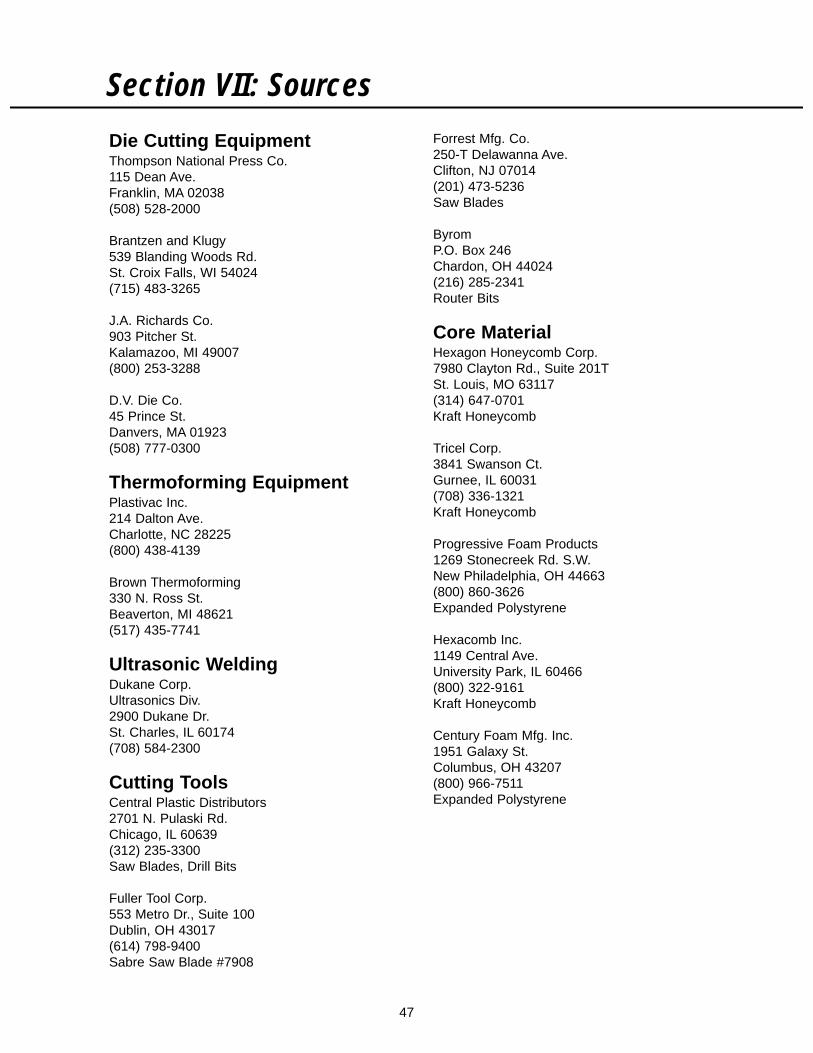
47
Section VII: Sources
Die Cutting EquipmentThompson National Press Co.115 Dean Ave.Franklin, MA 02038(508) 528-2000
Brantzen and Klugy539 Blanding Woods Rd.St. Croix Falls, WI 54024(715) 483-3265
J.A. Richards Co.903 Pitcher St.Kalamazoo, MI 49007(800) 253-3288
D.V. Die Co.45 Prince St.Danvers, MA 01923(508) 777-0300
Thermoforming EquipmentPlastivac Inc.214 Dalton Ave.Charlotte, NC 28225(800) 438-4139
Brown Thermoforming330 N. Ross St.Beaverton, MI 48621(517) 435-7741
Ultrasonic WeldingDukane Corp.Ultrasonics Div.2900 Dukane Dr.St. Charles, IL 60174(708) 584-2300
Cutting ToolsCentral Plastic Distributors2701 N. Pulaski Rd.Chicago, IL 60639(312) 235-3300Saw Blades, Drill Bits
Fuller Tool Corp.553 Metro Dr., Suite 100Dublin, OH 43017(614) 798-9400Sabre Saw Blade #7908
Forrest Mfg. Co.250-T Delawanna Ave.Clifton, NJ 07014(201) 473-5236Saw Blades
ByromP.O. Box 246Chardon, OH 44024(216) 285-2341Router Bits
Core MaterialHexagon Honeycomb Corp.7980 Clayton Rd., Suite 201TSt. Louis, MO 63117(314) 647-0701Kraft Honeycomb
Tricel Corp.3841 Swanson Ct.Gurnee, IL 60031(708) 336-1321Kraft Honeycomb
Progressive Foam Products1269 Stonecreek Rd. S.W.New Philadelphia, OH 44663(800) 860-3626Expanded Polystyrene
Hexacomb Inc.1149 Central Ave.University Park, IL 60466(800) 322-9161Kraft Honeycomb
Century Foam Mfg. Inc.1951 Galaxy St.Columbus, OH 43207(800) 966-7511Expanded Polystyrene

48
Notes