TABLE OF CONTENTS CONCEPTUAL SPECIFICATION
576
U Hotels & Resorts EU Technical Standards Manual i TABLE OF CONTENTS CONCEPTUAL SPECIFICATION DESCRIPTION PAGE INTRODUCTION 2 GENERAL CONCEPT 9 ROOMS 19 BATHROOM 64 SUITES 71 CORRIDORS 74 SURROUNDINGS DESIGN 79 RECEPTION 84 PUBLIC CORRIDORS & SHOPS 97 CUSTOMER SERVICES 108 RESTAURANTS AND BARS 128 CONFERENCE AND FUNCTIONS 153 ADMINISTRATION 168 LAUNDRY 172 KITCHENS 185 COLD ROOMS 236 SUPPLY AND WASTE 243 EMPLOYEES 250 TECHNICAL ROOMS 256
Transcript of TABLE OF CONTENTS CONCEPTUAL SPECIFICATION

U Hotels & Resorts EU Technical Standards Manual
i
TABLE OF CONTENTS
CONCEPTUAL SPECIFICATION
DESCRIPTION PAGE
INTRODUCTION 2
GENERAL CONCEPT 9
ROOMS 19
BATHROOM 64
SUITES 71
CORRIDORS 74
SURROUNDINGS DESIGN 79
RECEPTION 84
PUBLIC CORRIDORS & SHOPS 97
CUSTOMER SERVICES 108
RESTAURANTS AND BARS 128
CONFERENCE AND FUNCTIONS 153
ADMINISTRATION 168
LAUNDRY 172
KITCHENS 185
COLD ROOMS 236
SUPPLY AND WASTE 243
EMPLOYEES 250
TECHNICAL ROOMS 256

U Hotels & Resorts EU Technical Standards Manual
ii
FIRE SAFETY 268
SOUND CONTROL & INSULATION 284
SIGNAGE 298
THE DISABLED 320
WATERPROOFING 326
EXTERIOR JOINERY (WOOD AND METAL WORK AND GLAZING) 334
INTERIOR JOINERY 339
LOCKS 347
CLOSURE 357
FINISHES 361
SANITARY PLUMBING 373
FIRE PROTECTION 414
FIRE DETECTION 424
VENTILATION – AIR CONDITIONING 438
ELECTRICITY 453
IT & LOW VOLTAGE 484
TELEPHONE 531
ELEVATORS (LIFTS) 542
FF & E (FURNITURE, FIXTURES AND EQUIPMENT) 554
SPARE PARTS 560
TAKEOVER BY HOTEL OPERATOR 572

U Hotels & Resorts EU Technical Standards Manual
Page 1 To reach table of contents, press CTRL+Home for PC/ fn+left arrow for Mac
Introduction
These documents are strictly confidential
All rights are strictly reserved
Reproduction or issue to third parties in any form whatsoever is not permitted without prior written authorisation from the proprietor

U Hotels & Resorts EU Technical Standards Manual
Page 2 To reach table of contents, press CTRL+Home for PC/ fn+left arrow for Mac
INTRODUCTION
Purpose of these standards
Validity of these standards
U HOTELS & RESORTS EU technical documents list
Design team members and consultants
Pre-opening timeline area requirements
Acceptance of work

U Hotels & Resorts EU Technical Standards Manual
Page 3 To reach table of contents, press CTRL+Home for PC/ fn+left arrow for Mac
PURPOSE OF THESE STANDARDS
This manual deals with architectural and technical design standards. This manual is associated with all documents useful for the design, construction
and maintenance of U Hotels & Resorts and listed under “Technical Documents List”.
These standards have been produced for designers so that throughout the hotel project development process they may check the functional, qualitative
and technical criteria have been taken into account, which should guarantee the owning companies and U Hotels & Resorts:
The best operating facilities
The greatest ease in the operation and maintenance of the installations
The continuous development of the good reputation of the chain and the implementation of its corporate image.
These documents indicate the general architectural and technical criteria from which the specific projects should be produced.
U Hotels & Resorts standards must be strictly applied with the only exceptions being:
Waiver scheduled in the specific Hotel Brief
Waiver accepted in writing by U Hotels and Resorts Management during the design of the hotel
Local codes supersedes the standards of these documents
These standards are presented in two parts:
a. Conceptual specifications - room analysis
b. Technical specifications - trade analysis

U Hotels & Resorts EU Technical Standards Manual
Page 4 To reach table of contents, press CTRL+Home for PC/ fn+left arrow for Mac
VALIDITY OF THESE STANDARDS
This manual of standards is general and complementary to the detailed specific Hotel Brief. If on certain points of details there may be a contradiction,
the Hotel Brief has priority.
No waiver to the specifications may be considered without the prior agreement of U Hotels and Resorts Management who are the sole judge of the
interpretation and updating of these standards.
U HOTELS & RESORTS EU TECHNICAL DOCUMENT LIST
Facility Brief*
Hotel Brief *
Food & Beverage Brief*
Corporate Identity Manual
Design Guidelines
Technical Standards (this manual)
IT Standards (included in this manual)
(*) Written for each specific project, therefore only valid for that specific hotel

U Hotels & Resorts EU Technical Standards Manual
Page 5 To reach table of contents, press CTRL+Home for PC/ fn+left arrow for Mac
DESIGN TEAM MEMBERS AND CONSULTANTS
To ensure that the design of a hotel evolves correctly, the presence of the following parties in the team are indispensable:
Required from the beginning of the project:
A Technical Representative or Delegate of the owning company
A Technical Representative of U Hotels and Resorts Management
A Project Manager & Construction Site Management
An Architect
A Structural Engineer
An MEP Engineer (Mechanical, Electrical, Plumbing, HAVAC)
An IT – Network Engineer (IPTV, IP PBX, CCTV (IP), Internet/Wi-Fi)
An Interior Designer
A Kitchen Consultant or Kitchen Supplier who can work on layout drawings and M&E drawings
The following consultants are required depending on the project:
An Acoustics Consultant
A Lighting Consultant
A Landscape Architect
A SPA specialist
A Purchasing Office and FF & E consultant
A Laundry Consultant (usually combined with a Kitchen Designer)
Any other consultants as needed, such as quality surveyors, official control firm etc.

U Hotels & Resorts EU Technical Standards Manual
Page 6 To reach table of contents, press CTRL+Home for PC/ fn+left arrow for Mac
PRE-OPENING TIMELINE AREA REQUIREMENTS
To ensure the opening is structured and organized, it is necessary that certain premises are available to the operator at some point in advance during the
pre-opening period.
The table on the following page indicates, for the premises or equipment concerned, the availability datelines required before the opening date. These
datelines are expressed in weeks.
All the final keys or cards to the premises are handed over to the operator as and when they are set into service.
The below pre-opening schedule is given as example:

U Hotels & Resorts EU Technical Standards Manual
Page 7 To reach table of contents, press CTRL+Home for PC/ fn+left arrow for Mac
Section Location Remark
Pre Opening Office -22 -20 -18 -16 -14 -12 -10 -8 -6 -4 -2 Opening
General Managers Office Back of House
Human Resources Office Back of House
Offices, Accounting, F&B, HK Back of House
Canteen Back of House Before hand it should be leased out
Locker Rooms Back of House
Training Room Back of House
Toilets Back of House Locker room toilets
Front Office - Back Office Behind front office counter
Server Room Within the back office
Stores
Pre Opening FFE & OPE Function Rooms Floor covering should be temporary to avoid damage
General Store Back of House
F&B Stores Back of House
Laundry Back of House
House Keeping Back of House
Uniform Room Back of House For Pre-Opening Polo shirts would be used
Operations Back of House
Receiving
Production Kitchen To be ready for canteen food
Show kitchen Cooking training will be done in this kitchen
Pantry Function Room
Deli Bar & Kitchen With PMS connection
Bar Lounge With PMS connection
Engineering Workshop
Garbage Rooms Will be required and clearing would need to be organized
Operations Front of House
Front Office Lobby 3 weeks out, the PMS needs to be installed in this area
Main Restaurant 2 weeks out, the POS needs to be installed in this area
Bar Lounge 2 weeks out, the POS needs to be installed in this area
Deli - Restaurant 2 weeks out, the POS needs to be installed in this area
Spa 2 weeks out, the POS needs to be installed in this area
Gym / Fitness
Pool
Kids and Teenager Club
Library
Ballroom Will be used for staff meetings / briefings
Meeting Rooms
Elevator Give enough trial runs to get balance correct
Car Park
Rooms first lot To setup and train the housekeeping employees
Rooms second lot
General clean up work All suroundings Entire hotel team will walk property
Pre Opening Timeline Area Requirements
Please note in the green these areas will be required by the hotel operations for operational or storage or training purposes.
Required Dates
Requires, internet 4-Mpbs, phone connection, fax, copier,
furniture, as well working toilets during the pre-opening time
period.
Server racks, power, internet & lane cabling to be ready at
stated time for configuration of PMS & POS system

U Hotels & Resorts EU Technical Standards Manual
Page 8 To reach table of contents, press CTRL+Home for PC/ fn+left arrow for Mac
ACCEPTANCE OF WORK
Work per area is accepted by the Owners with the assistance of the persons mentioned in the “Design Team Members and Consultants” section, in respect
of the individual person’s specific input into the project. This acceptance must be made in the presence of the U Hotels and Resorts Management Team
which, except when otherwise arranged, will not take charge of the premises beforehand.
If partial or total opening of the uncompleted hotel is necessary due to commercial requirements, it does not indicate any acceptance of the work or
acceptance by U Hotels and Resorts of completion. Responsibility for non-accepted works cannot be apportioned to the operator in any way and should be
acknowledged by the Owner in writing during the handover.
The technical documents, operating instructions and as-built drawings should have been handed over to the hotel General Management at the moment of
acceptance or at the hotel takeover at the very latest.
Only the date of acceptance and not that of the possible takeover marks the start of the warranty period provided by the building contractors.
At the takeover of the premises, U Hotels and Resorts Management will write a technical report listing the deficiencies in the property from a hotel
operation point of view.
“See chapter Hotel Takeover”

U Hotels & Resorts EU Technical Standards Manual
Page 9 To reach table of contents, press CTRL+Home for PC/ fn+left arrow for Mac
GENERAL CONCEPT
General
Types of hotels
Characteristics specific to resort hotels
Size
Guest traffic
Luggage traffic

U Hotels & Resorts EU Technical Standards Manual
Page 10 To reach table of contents, press CTRL+Home for PC/ fn+left arrow for Mac
GENERAL
U Hotels and Resorts Management/Owner must follow a certain number of fundamental criteria which ensures that the hotel is easily perceived and
identified as a U Hotel or Resort. Furthermore, these criteria must contribute to strengthening the U Hotels & Resorts corporate identity. These criteria
guide the major aspects of the studies.
U Hotels & Resorts brand values:
Reach out
Brand appeals to high achievers even when on holiday or business who have clear and
consistent expectations and know what constitutes value and quality in their lives.
Restore
Cosseting and comfortable hotels and resorts, where welcoming and friendly employees will
refresh and rejuvenate guests with products, facilities and services delivered in an informal
environment. Guests will feel part of the family.
Reconnect
Through locations and warm uncomplicated service that encourages guests to step into the
local environment and experience its culture and heritage at their own pace, creating a
memorable, unique experience.
Location
A good location is the key to the success of any hotel project. With a poor location, even if the hotel itself is of high quality it will never enjoy total
commercial success.
U Hotels & Resorts EU Technical Standards Manual
Page 11 To reach table of contents, press CTRL+Home for PC/ fn+left arrow for Mac
Adaptation to the Site
Each project must be the subject of an architectural study. It is not necessary to follow a given approach based on a standard design. The landscape,
relief and surrounding environment must be integrated as essential elements in the overall architectural concept.
Protection of the Environment
Protection of the environment is a central component in U Hotels & Resorts’ positioning. This commitment must be taken into account right from the
initial studies and be reflected in the choice of installations and equipment. In particular, the following aspects must be considered:
Energy savings (VRV units, LED light, sensor switches)
Quality of the ambient air and external emissions
Water quality and limiting consumption, as well as pre-treatment, treatment or reuse of water
Absence of noise pollution
Conditions for storage or confinement of dangerous and/or toxic products
No use of toxic materials for construction or in equipment (asbestos, CFC, PBC, etc.)
Certain technologies, such as computerized maintenance aids, non-toxic replacement materials, etc., should be considered throughout the project
development phase. Whenever possible, these alternatives will be given priority.
Organisation of Space
The architectural concept must offer guests simple and easily recognizable spaces and volumes. The public areas will be limited to two or three levels.
Large architectural areas such as an atrium are desired, and must have a link to the public activities at the base (lobby, bars, restaurants, gym, pool
etc.).

U Hotels & Resorts EU Technical Standards Manual
Page 12 To reach table of contents, press CTRL+Home for PC/ fn+left arrow for Mac
An Innovative Character
The hotel must be designed down to the last detail long before it begins operating. Consequently, it must be designed to be competitive at the time it
enters the market. This means planning with a very open mind when it comes to new or innovative concepts that will distinguish the hotel from the
competition.
A Timeless Character
For the architecture, interior design and equipment, “quality” above all means solid and robust. It is better to rely on traditional, natural methods and
materials.
Access
Given the various imperatives involved, the hotel’s surroundings should, as far as is possible, consist of a carefully designed and landscaped
environment, while ensuring the visibility of the hotel. There should not be a series of access ramps. Guests should not have to cross large, exposed
and cold expanses (made of mineral materials), such as parking areas to get to the entrance of the hotel.
Orientation
The hotel’s position should take maximum advantage of surrounding views, sun and daylight to enable guests to enjoy the view, particularly in the
lounges, restaurants, public areas and rooms.
Wind Exposure
It is imperative that drafts and other undesirable effects of wind (heat or cold, spreading of odours, smoke, etc.) be limited for the room balconies
and public terraces as well as the swimming pool areas.
Noise Protection
Appropriate measures must be taken to protect against noise from roads, airports, hotel machinery and equipment, nearby pubs and nightclubs, etc.

U Hotels & Resorts EU Technical Standards Manual
Page 13 To reach table of contents, press CTRL+Home for PC/ fn+left arrow for Mac
Landscaping
Even when there is no land available around the hotel, landscaping is an extremely important factor in creating a quality property. A specific study
by a specialist is always required, even if only the terraces and rooftops are visible to guests.

U Hotels & Resorts EU Technical Standards Manual
Page 14 To reach table of contents, press CTRL+Home for PC/ fn+left arrow for Mac
TYPES OF HOTELS
There are two main types of hotels:
Resort Hotels
Resort hotels are often located on beaches or in particularly pleasant natural sites and feature larger outside areas. Here, the terrain offers space for
leisure activities including water sports, swimming pools, landscaped waterfalls, kid’s playground, botanical gardens, a golf course or other such
activities.
Business Hotels
The constructed space sometimes occupies the entire site minus the boundary size limitation. Some business hotels are also located in low - density
urban zones, where construction may leave room for access roads, parking lots and gardens. This enables greater flexibility in the layout of the
buildings.

U Hotels & Resorts EU Technical Standards Manual
Page 15 To reach table of contents, press CTRL+Home for PC/ fn+left arrow for Mac
CHARACTERISTICS SPECIFIC TO RESORT HOTELS
The approach for the creation of a “resort hotel” is different from that of a “business hotel”; to start with the degree of efficiency sought is not the
same. In urban areas with reduced plot areas, there is a certain density, with short, efficient paths between different areas required for guests in a hurry
who reside at the hotel on a short-term basis. On the other hand resort hotels welcome guests for a number of days which are entirely dedicated to rest,
relaxation and entertainment. The sites are larger and guests have time to walk around and enjoy the surroundings created for them. Open spaces,
gardens, points of interest and places for relaxing and enjoying life are all elements which must be a central part of the resort concept.
The following aspects lead the main directions of the studies carried out:
The hotel must be a pleasant place. This starts with the provision of places for relaxation, but also for meeting other people during evening get-
togethers, shows or other forms of entertainment. The organization of the spaces in which the guests live in the hotel must foster and encourage such
exchanges. Equally important in creating a pleasant ambiance as per the policy of the hotel’s operator to welcome, inform, meet and organize activities
for guests, taking advantage of the multiple facilities available.
The hotel must live up to the guest’s expectations. People choose to go to these hotels to escape from the stress of everyday life. They want to be
enchanted and charmed in an exotic place amid peace which they cannot find at home. They want a change of scene that is far removed from their
everyday concerns. The dreamlike character of the hotel and its strong “personality” must offer all these things to guests and create a desire to stay at
the hotel and to wish to return. The magic of the site must be found in the concept proposed by the architect in response to the U Hotels & Resort’s
Hotel Brief. This is the main responsibility of the architect, in conjunction with the landscape architect.
Landscaping: Whatever the size of the site, the resort hotel is first and foremost a “beautiful garden”. The gardens are the dominant and even priority
element in the composition of the hotel, integrating one or more centres of interest (pool, restaurant, bar, beach, island, etc.). These are the points
which attract guests during their stay. Whether the garden is very formally constructed or more freestyle in design, the vegetation must be carefully
chosen and adapted to the climate. The enticing colours and spaces full of charm, light and decor, must make the gardens places to be lived in and
seen, and this decor must be discovered progressively thanks to a seamless transition between different areas.
The character and climate of the area: The hotel must be integrated into the surroundings and the creation of a harmonious whole is essential. The
layout plan respects the topography and vegetation, if they are remarkable and a “talking point”. The buildings too may express a strong link with the
location and take advantage of certain elements, finding inspiration in the forms and principles behind local traditional cultural, architectural and
historical aspects area (if applicable).
U Hotels & Resorts EU Technical Standards Manual
Page 16 To reach table of contents, press CTRL+Home for PC/ fn+left arrow for Mac
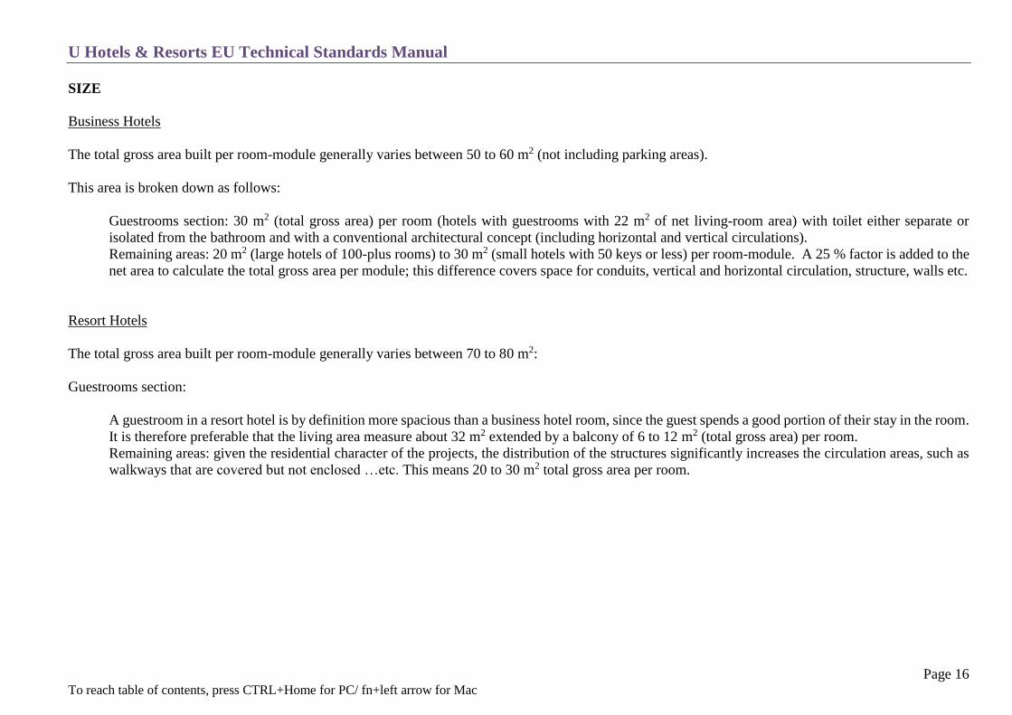
SIZE
Business Hotels
The total gross area built per room-module generally varies between 50 to 60 m2 (not including parking areas).
This area is broken down as follows:
Guestrooms section: 30 m2 (total gross area) per room (hotels with guestrooms with 22 m2 of net living-room area) with toilet either separate or
isolated from the bathroom and with a conventional architectural concept (including horizontal and vertical circulations).
Remaining areas: 20 m2 (large hotels of 100-plus rooms) to 30 m2 (small hotels with 50 keys or less) per room-module. A 25 % factor is added to the
net area to calculate the total gross area per module; this difference covers space for conduits, vertical and horizontal circulation, structure, walls etc.
Resort Hotels
The total gross area built per room-module generally varies between 70 to 80 m2:
Guestrooms section:
A guestroom in a resort hotel is by definition more spacious than a business hotel room, since the guest spends a good portion of their stay in the room.
It is therefore preferable that the living area measure about 32 m2 extended by a balcony of 6 to 12 m2 (total gross area) per room.
Remaining areas: given the residential character of the projects, the distribution of the structures significantly increases the circulation areas, such as
walkways that are covered but not enclosed …etc. This means 20 to 30 m2 total gross area per room.

U Hotels & Resorts EU Technical Standards Manual
Page 17 To reach table of contents, press CTRL+Home for PC/ fn+left arrow for Mac
GUEST TRAFFIC

U Hotels & Resorts EU Technical Standards Manual
Page 18 To reach table of contents, press CTRL+Home for PC/ fn+left arrow for Mac
LUGGAGE TRAFFIC
1. Customer arrival flow to guest rooms. This depends on the Porte Cochere design but the luggage room should have a separate entrance from the Porte
Cochere with another entrance to the back of house which leads to the service elevator. This ensures no luggage is circulated through the public areas.
2. Flow from the guest rooms to the Porte Cochere (departure).
3. Long term luggage deposit should be separated for better security (large hotels only).
U Hotels & Resorts EU Technical Standards Manual
Page 19 To reach table of contents, press CTRL+Home for PC/ fn+left arrow for Mac
ROOMS
Concept
Architecture
Dimensions
Organisation
Decor
Equipment
Coverings
Furniture
Bedding Material Specification
U Hotels & Resorts EU Technical Standards Manual
Page 20 To reach table of contents, press CTRL+Home for PC/ fn+left arrow for Mac
CONCEPT
The room concept varies depending on whether the hotel is a “city centre business” property or a “resort” hotel. However, sometimes there is no clearly
defined line between the two types. The Hotel Brief must therefore define the type of hotel and the limits to be respected in terms of the concept.
In all cases, a complete mock-up room, including bathroom and corridor, must be built on site or in an agreed-upon location for each room type (one king &
one twin with connecting door minimum) and subjected to a detailed analysis. If necessary it must be corrected and revised before any final approval is
granted by U Hotels and Resorts Management. This approval must be received before any architectural or decorative (interior design) work can begin or
orders be placed.
“Business” Hotels
Business hotels have rooms with a residential character. The main functions of these rooms (rest, sleep and work) are treated on the basis of concepts
which avoid copying the outmoded “bed in a box” idea of standard hotel chain rooms, which are both too anonymous and unvarying from one country
to the next.
For U Hotels & Resorts, each new project is covered by a specific study for the standard room. This means that there is no such thing as a “standard”
U Hotels & Resorts room layout.
“Resort” Hotels
Resort-oriented hotels are different from business-oriented hotels in that the character emphasizes relaxation, rest and taking a break. The climate and
the site both have great influence on the concept. Consequently, the room must have a more innovative image that makes optimum use of space and
light. The room is opened to the outside with a terrace or balcony, which actively contribute to the “life” of the room.
The sleep/night function can be considered as distinct from the living room/terrace function. The bathroom must be spacious and largely opening on
to the room, possibly becoming an extension of the room itself (the boundary is changeable). The room must have natural lighting and if possible a
view of the sea or gardens. The comfort and layout/amenities must be designed to accommodate longer stays than at business hotels.

U Hotels & Resorts EU Technical Standards Manual
Page 21 To reach table of contents, press CTRL+Home for PC/ fn+left arrow for Mac
ARCHITECTURE
The total area of the guestroom floors or sections in a hotel represents approximately two-thirds of the total constructed area. This means that the way in
which the rooms are grouped has a fundamental influence on the architecture of the hotel or the buildings which comprise the hotel. It is also important to
note, that this type of study begins two to three years before the hotel actually opens. This makes it necessary to look ahead in order to satisfy the expectations
of the guests who will be staying at the hotel in the future. Other factors to be taken into account right from the start of this concept phase are the following
points which have direct impact on the size and shapes of bay windows.
Protection of facades from the sun
Sound insulation from both interior and exterior noise (C 21 Sound Control & Insulation)
Cleaning of the facades
The railings of balconies must allow a clear view whilst guests are seated inside the room
It must be possible to totally block out all daylight inside the room
Windows and treatment of windows
Windows must be designed to provide sound insulation, based on a calculation of the sound levels generated by the outside environment. They must also be
thermally treated: dark tinted windows should not be used. Windows should always have a section which can be opened. Where necessary, for safety and
security reasons, the opening section shall be equipped with a “stop” preventing it from being opened more than local regulations allow (especially when
children have access).
Where windows lead on to a terrace or balcony, safety shall also be taken into account, in accordance with applicable regulations. In all cases, the minimum
height of the handrail of the balcony shall be 1.10 meter from the floor, or 95 cm from the highest stepping point. The smallest size of gaps between railings
such as iron bars (which must be vertical and not horizontally positioned) must not be bigger than 12 cm.

U Hotels & Resorts EU Technical Standards Manual
Page 22 To reach table of contents, press CTRL+Home for PC/ fn+left arrow for Mac
DIMENSIONS
The net area of a standard room-module is around 28 m2. The main area of the room excluding the bathroom should measure 22 m2.
The minimum central distance between the walls of the module is 3.8 m, and the overhead clearance of the ceiling is a minimum of 2.80 m in the
room and 2.40 m in the bathroom and entrance.
All specific information and exceptions, in particular for renovation of existing buildings, are included in the Hotel Brief. The final dimensions and
exact position of the walls and partitions which are part of the structural design may not by finalized until the organization of the room module has
been defined and approved. The number and location of these rooms is determined by conforming with local regulations; this information is included
in the Hotel Brief.
ORGANISATION
The following must be provided within the rooms with no exceptions;
An entrance which acts as a small hallway, avoiding a direct view of the bed.
A closet with shelves, drawers, a safe and a wardrobe.
A bathroom with 1 wash basin and vanity counter and separate shower stall and toilet which may be enclosed within a cubical.
A sleeping area with absorption type mini-bar and digital operated television, with a minimum of 40” to 43” screen size (depend on brand), which
streams 6 to 8 different music genres.
A work corner with desk, business unit and appropriate equipment (business hotels only).
An area with sofa (suites only), armchair and coffee table.
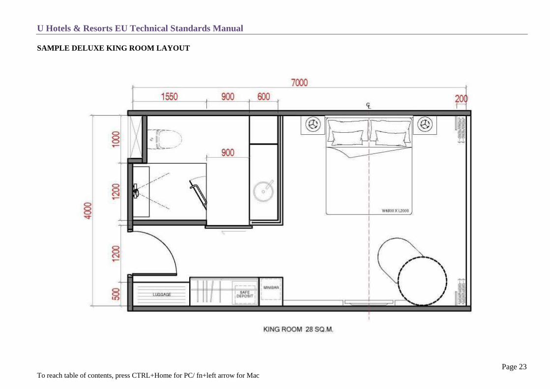
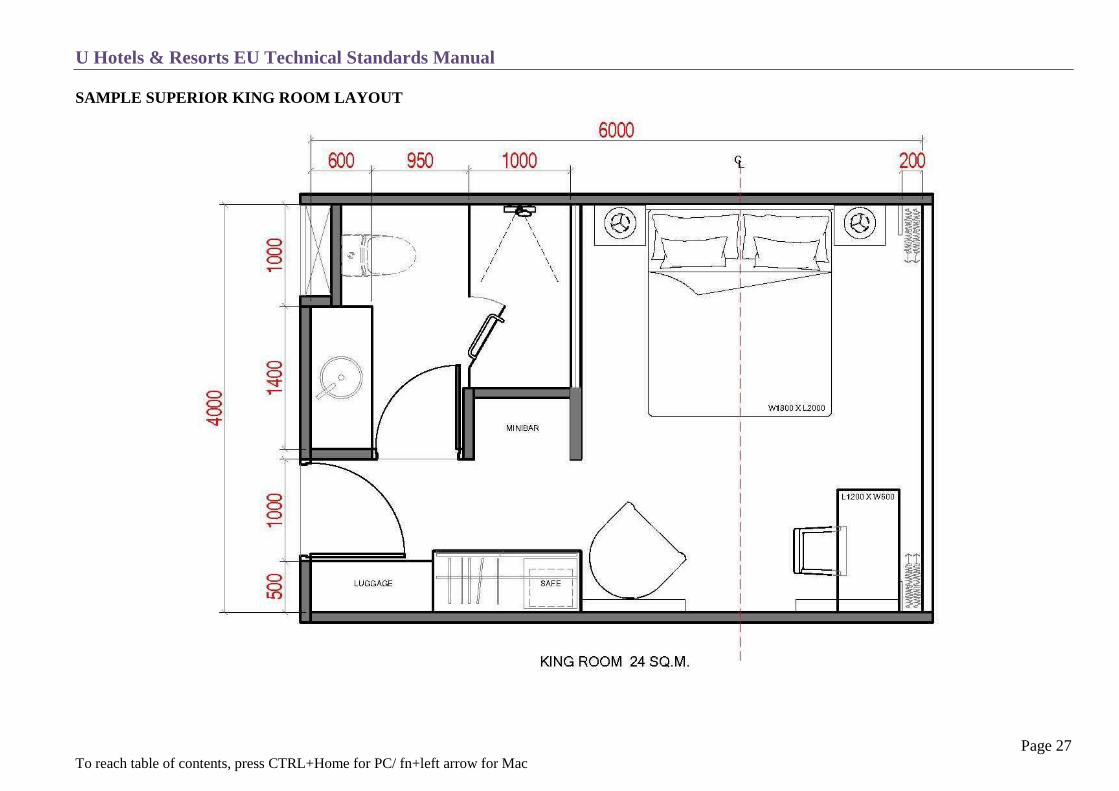
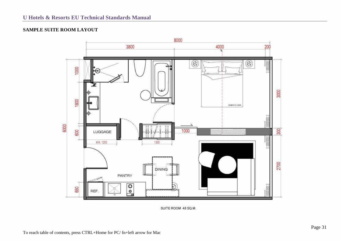
Significant variations are possible, as illustrated by some U Hotels & Resorts hotel guestrooms layouts (see below drawings).
U Hotels & Resorts EU Technical Standards Manual
Page 23 To reach table of contents, press CTRL+Home for PC/ fn+left arrow for Mac
SAMPLE DELUXE KING ROOM LAYOUT

U Hotels & Resorts EU Technical Standards Manual
Page 24 To reach table of contents, press CTRL+Home for PC/ fn+left arrow for Mac
SAMPLE DELUXE KING ROOM M&E SPECIFICATION

U Hotels & Resorts EU Technical Standards Manual
Page 25 To reach table of contents, press CTRL+Home for PC/ fn+left arrow for Mac
SAMPLE DELUXE TWIN ROOM LAYOUT

U Hotels & Resorts EU Technical Standards Manual
Page 26 To reach table of contents, press CTRL+Home for PC/ fn+left arrow for Mac
SAMPLE DELUXE TWIN ROOM M&E SPECIFICATION
U Hotels & Resorts EU Technical Standards Manual
Page 27 To reach table of contents, press CTRL+Home for PC/ fn+left arrow for Mac
SAMPLE SUPERIOR KING ROOM LAYOUT

U Hotels & Resorts EU Technical Standards Manual
Page 28 To reach table of contents, press CTRL+Home for PC/ fn+left arrow for Mac
SAMPLE SUPERIOR KING ROOM M&E SPECIFICATION

U Hotels & Resorts EU Technical Standards Manual
Page 29 To reach table of contents, press CTRL+Home for PC/ fn+left arrow for Mac
SAMPLE SUPERIOR TWIN ROOM LAYOUT

U Hotels & Resorts EU Technical Standards Manual
Page 30 To reach table of contents, press CTRL+Home for PC/ fn+left arrow for Mac
SAMPLE SUPERIOR TWIN M&E SPECIFICATION
U Hotels & Resorts EU Technical Standards Manual
Page 31 To reach table of contents, press CTRL+Home for PC/ fn+left arrow for Mac
SAMPLE SUITE ROOM LAYOUT
U Hotels & Resorts EU Technical Standards Manual
Page 32 To reach table of contents, press CTRL+Home for PC/ fn+left arrow for Mac
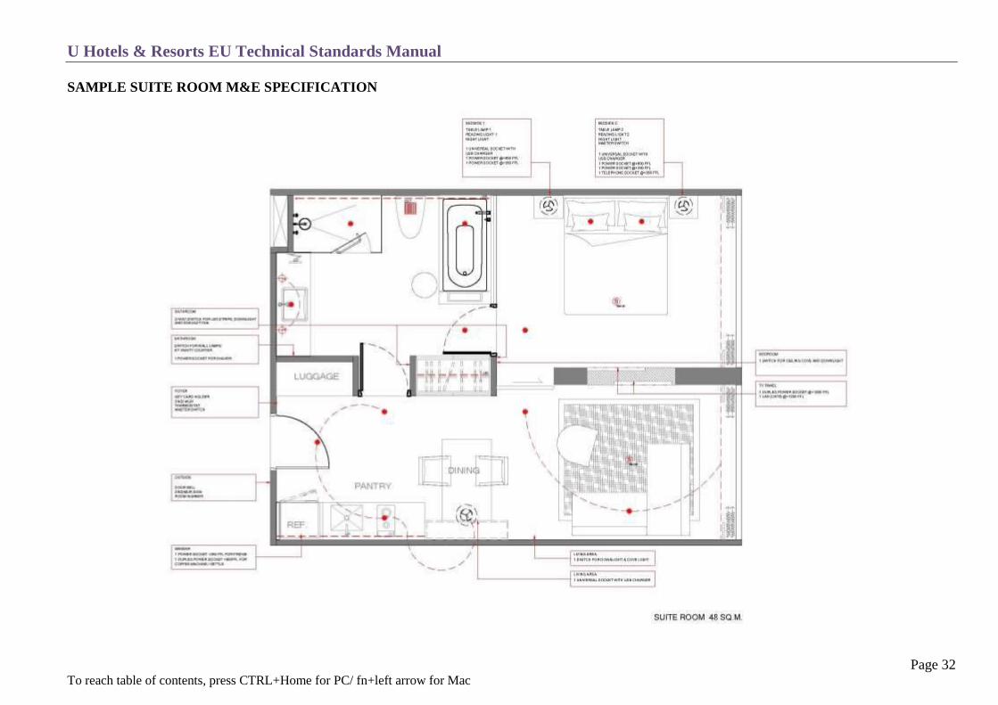
SAMPLE SUITE ROOM M&E SPECIFICATION

U Hotels & Resorts EU Technical Standards Manual
Page 33 To reach table of contents, press CTRL+Home for PC/ fn+left arrow for Mac
SAMPLE ROOM ELEVATION

U Hotels & Resorts EU Technical Standards Manual
Page 34 To reach table of contents, press CTRL+Home for PC/ fn+left arrow for Mac
DECOR
The first visual impression of the room is the one perceived when the entrance door is opened. This impression must immediately convey a sense of
intimacy, calm and comfort through the colours, lighting and heat or freshness.
The harmony of the colours will vary according to the climate and the ambiance to be created, but must always remain consistent with the creation of a
uniformly high quality atmosphere. The decor must create a “local and homely” atmosphere in the room. Each room will be personalized with items such
as lithographs, art works, etc. Technology is present to cover all guest needs, but must remain discreet.
EQUIPMENT
Lighting must be carefully designed, with two types of lighting:
Ambient lighting, providing overall illumination of the room
Specific lighting for the desk, lounge area and for reading
Electrical equipment must include the following:
Entrance
1 master switch with micro-switch (this switch must not turn off the air-conditioning, refrigerator, IPTV and one power socket at work station)
1 two-way lighting switch for the ambient lighting (room and entrance)
1 switch for the bathroom lighting
1 outlet to allow housekeeping to use their equipment when cleaning the room (within the room/corridor)
Touch-contact or switch for the closet light
Bell for the entrance door including the DND / MUR indicators
Entrance and door lighting
Thermostat to control the room temperature

U Hotels & Resorts EU Technical Standards Manual
Page 35 To reach table of contents, press CTRL+Home for PC/ fn+left arrow for Mac
Bedroom
There should be a minimum of five light points (plus the reading lights), providing overall illumination of 150 lux. The minimum equipment is as
follows:
1 reading lamp on the desk (350 lux).
1 ambient light with two-way switch (one at the entrance).
Lighting for the mini-bar /TV cabinet.
1 free standing decorative light fixture at the seating area or day lounge.
Artwork lights.
Lighting for the balcony (if applicable).
“DND” (do not disturb) and “MUR” (make up room) switch.
The quality of the reading lights – at the bed, desk and armchair – is one of the factors which makes the room comfortable. These lights must be
carefully selected and must be sufficiently powerful to be connected via individual switches.
A number of electrical and low-voltage outlets must be provided in the room:
Wall outlets with extensions for bedside, desk and lounge lighting.
TV outlet RJ45 connected with CAT6e (TV with infrared remote control unit).
TV speaker jack (for the bathroom).
Mini-bar refrigerator outlet plus special connection if the hotel has computerized mini bar management. An RJ45 CAT 6E Ethernet circuit outlet
must be provided in all cases (see chapter T13 IT & Low Voltage, section 2 on structured cabling).
2 electrical outlets which include USB charger near or at the desk (lamp + computer) on a support that is easily accessible and coordinated with the
desk. This outlet will always be operated and not connected to the key card.
1 RJ45 telephone outlet at the main bedside (window side) connected to the in room router.
A switch near the window for the balcony light which must not be hidden by the curtains.
Each hotel room must have a bell which includes the DND / MUR indicators.
For equipment on the bedside table (lamp, telephone, etc.) and the room in general the cords should be of the same type and colour, and as short as
possible.
The switches and outlet face plates must match and follow the décor appropriately. It is preferable that these are not in white, except with white
finishes.

U Hotels & Resorts EU Technical Standards Manual
Page 36 To reach table of contents, press CTRL+Home for PC/ fn+left arrow for Mac
Telephone
One telephone line per room: (See chapter T13 IT & Low Voltage)
Phone on the bedside table close to the window side (wireless if possible). Telephone outlet should be under side table, hidden from guest sight.
Television – Radio
LED Hospitality TV sets with built in set top box, must be colour with stereo sound, multi standard and equipped to receive cable and satellite.
They must also feature a HDMI / USB socket, 50 channel minimum availability and an infrared remote control unit.
LED TV with a minimum size of 41" to 46”. For suites within the living room a minimum of 46" or larger is required. The TV should be visible from the bed and the reading/sitting area in the suites. It must have a swivel mount and/or be placed on top of a cabinet.
The middle of the screen should be about 1.35 m from the floor.
An alarm clock should be provided on the night table.
Fire Safety (see chapters T-9 Fire Protection and T-10 Fire Detection)
A smoke detector mounted in the centre of the room (above the bed) at the highest possible position.
An alarm must be recessed into the false ceiling over the entrance.
The above units need to be connected to a fire panel control board (Addressable) situated in the reception and engineering departments.
Air conditioning (see chapter T-11 Ventilation – Air Conditioning)
Fresh and centrally pre-treated air must be provided for the rooms and corridors.
Air outlets and intakes must be of a good quality to ensure that they integrate seamlessly with the interior design of the room.
Four-tube or two-tube fan coil units should be used, depending on the climate.
A wall-mounted thermostat with graduated temperature markings should be installed with on/off switch and three-speed fan control.
Sensor switch at Window or Balcony door to stop the Air Condition after 2 minutes of opening the window or door.
U Hotels & Resorts EU Technical Standards Manual
Page 37 To reach table of contents, press CTRL+Home for PC/ fn+left arrow for Mac
Locks
Guest Room Door Locks
Room locks should be standalone electronic RFID, programmable key types (Mifare or NFC with 1k or 4k capacity), battery operated and
interfaced with the PMS system (Comanche).
In humid, tropical and coastal climates, the provider of the systems must guarantee that their product can withstand local conditions.
It is recommended to use RFID door lock systems due to the security and reliability of contact-less technology. Due to today’s mobile gadgets the
lock system should be compatible with any preferable solution such as key cards, phones or other devices.
Recommended brands are Onity, VingCard or Kaba.
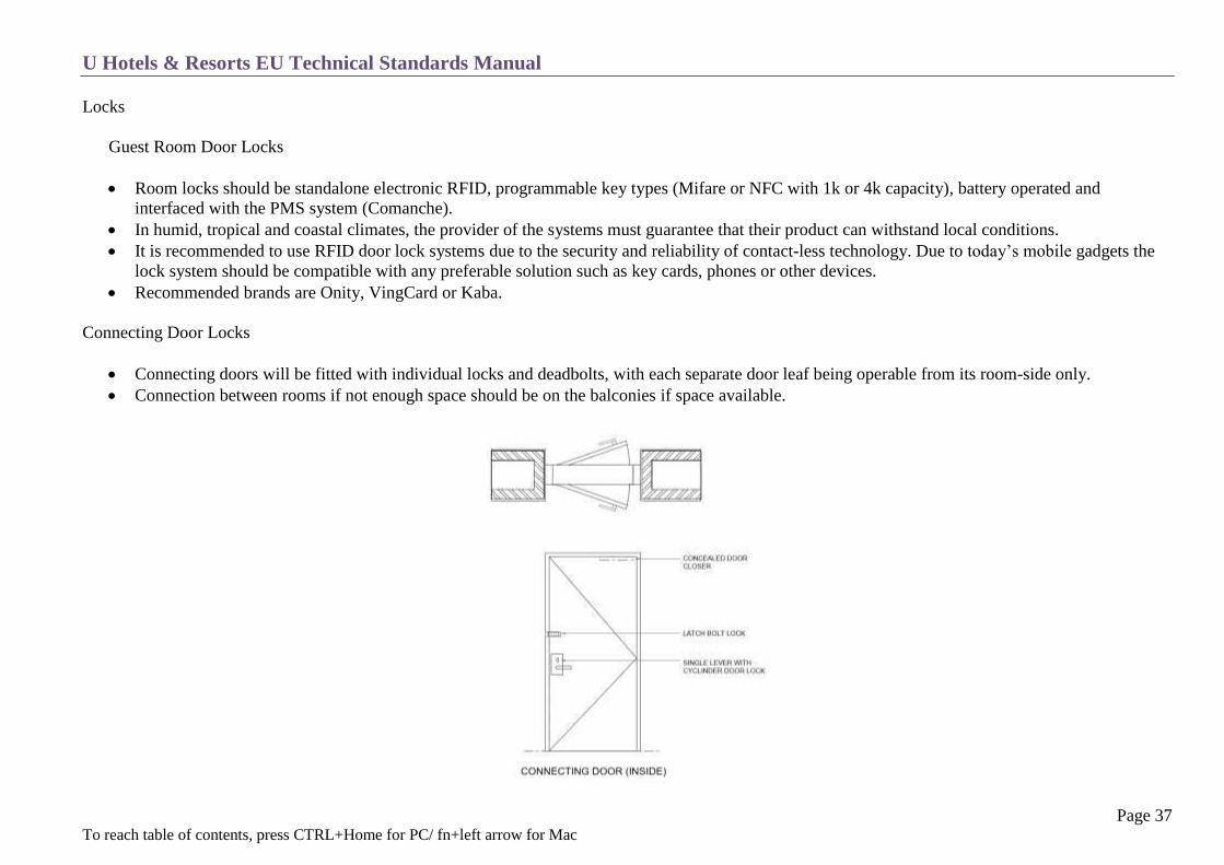
Connecting Door Locks
Connecting doors will be fitted with individual locks and deadbolts, with each separate door leaf being operable from its room-side only.
Connection between rooms if not enough space should be on the balconies if space available.

U Hotels & Resorts EU Technical Standards Manual
Page 38 To reach table of contents, press CTRL+Home for PC/ fn+left arrow for Mac
COVERINGS
Floor (see T7 – Finishes)
Axminster type carpets with 80/20 % wool/nylon weave should be used for business hotels in living rooms, corridors, function rooms etc. In-room
foyers should be a hard durable material such as stone or wood.
Ceramic or stone tiling with anti-slip treatment and carpet rugs by the bed are to be used in warm and humid climates or in resort hotels (a floating
floor for soundproofing is necessary in this case) .
Partial wooden floors are also possible, using the same precautions as above.
The skirting must be chosen to match the coverings: tile or solid wood a minimum 12.5 cm high from the floor.
The balcony floors should be recessed by 2 cm and covered with a hard antislip tiling and with a gradient of 1:100 (by 1m width = 1cm).
Floor transitions are 2cm or less, except for the shower cubical which is 3 cm with a gradient of 1:60.
Waterproofing in the bathroom with a floor drain must be provided.
Terrazzo and polished concrete finish is not recommended due to cracking after a short time period.
Walls
Materials which cannot be washed or which have a deep relief texture should be avoided.
Stucco finishes with 3mm thickness is recommended due to long life and low maintenance. This is especially good to camouflage small wall
bumps, cracks or other imperfections as this finish does not reflect light.
Water- based matte finish for guest rooms or flat enamel finishes for corridors or halls.

U Hotels & Resorts EU Technical Standards Manual
Page 39 To reach table of contents, press CTRL+Home for PC/ fn+left arrow for Mac
Doors
Acoustic seal around the entire frame and a threshold bar or telescopic skirting to ensure soundproofing.
Wide-angle (160˚) eyepiece or peephole with cover set at a height of 155 to 160 cm from the floor.
Magnetic doorstop which can hold the door open.
Door panel minimum thickness 3.5 cm.
Concealed door closer.
U-buckle lock.
Frame behind the door for fire safety diagrams and instructions.
Room number matching the decor (see chapter C 22 Signage).
All doors must be flame resistant with a withstanding rate of 1 ½ hour (90 minutes) minimum.
Connecting doors between guest rooms must be double and have double seals and rebates around the entire doors to guarantee total sound insulation
if they are not located on a balcony. They must have the same degree of flame resistance as the entrance doors and be equipped with a single handle
and a latch bolt.
The entrance door must be solid core type and all doors must meet acoustic insulation requirements. (Refer to chapter C21)
Kids’ safety lock on balcony doors are required at a height of 140 cm from the floor, if the building is a high rise.

U Hotels & Resorts EU Technical Standards Manual
Page 40 To reach table of contents, press CTRL+Home for PC/ fn+left arrow for Mac
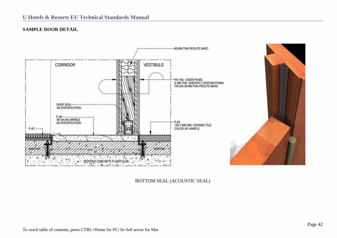
SAMPLE DOOR DETAIL

U Hotels & Resorts EU Technical Standards Manual
Page 41 To reach table of contents, press CTRL+Home for PC/ fn+left arrow for Mac
SAMPLE DOOR DETAIL
DOOR DETAIL
U Hotels & Resorts EU Technical Standards Manual
Page 42 To reach table of contents, press CTRL+Home for PC/ fn+left arrow for Mac
SAMPLE DOOR DETAIL
BOTTOM SEAL (ACOUSTIC SEAL)

U Hotels & Resorts EU Technical Standards Manual
Page 43 To reach table of contents, press CTRL+Home for PC/ fn+left arrow for Mac
Ceilings
The ceilings are a key factor in the overall decor, especially in the room (when viewed from a prone position on the bed).
Cornices or other decorative touches should be incorporated into flat ceilings.
It is recommended to have cove ceilings with indirect lighting with a minimal number of down light fixtures.
Large enough hatch at the entrance area (min. 80 x 60 cm) is required to be able to remove the fan coil unit. It is suggested to use the return air
grille for this purpose which is strong enough for repeat access.

U Hotels & Resorts EU Technical Standards Manual
Page 44 To reach table of contents, press CTRL+Home for PC/ fn+left arrow for Mac
FURNITURE
Closets or Wardrobes
Built-in furniture must use solid elements such as masonry, wood frames etc. The wardrobe is a high quality element with finishes that match the room
decor. Materials used could be hardwood, brass, stainless steel, mirrors, etc. at least 150 cm in length & 70 cm deep.
Closets or wardrobes must be divided into two sections:
o Hanging space with a shelf on top for extra pillows and a rod for hangers with a free space below the rod 170 cm & min. 100 cm in length.
o Drawer / shelf with 2 to 6 deep drawers 60 cm deep & 50 cm wide with cut out front panel, easy slide castors and a safety stop.
The two sections may be separated by providing a wardrobe plus a chest of drawers.

U Hotels & Resorts EU Technical Standards Manual
Page 45 To reach table of contents, press CTRL+Home for PC/ fn+left arrow for Mac
Furniture should include the following:
Electronic safe, placed on the drawer furniture and mounted to the wall at a height of min. 90 cm from the floor. Suggested size is to accommodate
at least a 15” laptop (HxWxD mm) 206x425x370 or 17” laptop 206x437x502. The safe must be battery operated with 4 or 6 digit key code and
digital LED display. Recommended brands (VingCard/Elsafe and Onity).
Frame mounted on the back of the room door to display the disclaimer for room rate, instructions and hotel responsibilities (only if required by local
legislation).
Foldable luggage rack (WxD cm) 75 x 60 if no built-in luggage rack is available.
Closet doors should be rollout type on nylon rollers (no rails on the floor) and equipped with noise dampers. Alternately, sets of double doors can be
used if they do not interfere with the corridor or the main door.
Closet-light position and shelf shape will allow proper illumination of the space, (recommend space saving LED rope light).
Auto light switch, (normal – on, push – off, turns off when cupboard door closes). Switch, 2mm depression required for operation and 5.5mm total
travel. Switching 1A max (250V), thermoplastic moulding.
Natural or artificial ventilation flow should be maintained at all times.
Additional details concerning the equipment defined above may be included in either the Hotel Brief or the guestroom FFE list.

U Hotels & Resorts EU Technical Standards Manual
Page 46 To reach table of contents, press CTRL+Home for PC/ fn+left arrow for Mac
Curtains
The bay windows and windows should be equipped as follows:
Sheer curtain, single rail - full width.
Lined curtains with a minimum 80% blackout rubber coat backing with the two rails overlapping at least 20 cm in the middle. Cleaning needs to be
guaranteed.
Curtain finishes a maximum 1 cm above the floor (depending on floor finish) |track has to be a minimum15 cm above the window | coving to hide
the tracks a min. 15 cm above the false ceiling and 20 cm wide for a double rail of sheer and lined curtain.
13 – 15 gliders per meter of track | 1 bracket per meter | 2 end return covers | drawing rod mounted to the gliders for easy movement.
Needs to be fire retardant, washable and stain resistant.
Both sides of the window require curtain cavities of about 30 cm to guarantee total blackout.

U Hotels & Resorts EU Technical Standards Manual
Page 47 To reach table of contents, press CTRL+Home for PC/ fn+left arrow for Mac
Luggage Racks
The luggage rack can be fixed preferably next to the closet.
It should have a back to protect the wall a minimum of 30 cm.
The minimum dimensions should be (LxHxD cm) 120 × 45 × 60.
The top may be covered with stone or solid wood with a hairline stainless steel bars or other hard surface if the rack is fixed.
U Hotels & Resorts EU Technical Standards Manual
Page 48 To reach table of contents, press CTRL+Home for PC/ fn+left arrow for Mac
Beds
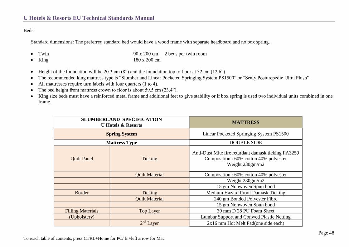
Standard dimensions: The preferred standard bed would have a wood frame with separate headboard and no box spring.
Twin 90 x 200 cm 2 beds per twin room
King 180 x 200 cm
Height of the foundation will be 20.3 cm (8”) and the foundation top to floor at 32 cm (12.6”).
The recommended king mattress type is “Slumberland Linear Pocketed Springing System PS1500” or “Sealy Posturepedic Ultra Plush”.
All mattresses require turn labels with four quarters (1 to 4).
The bed height from mattress crown to floor is about 59.5 cm (23.4”).
King size beds must have a reinforced metal frame and additional feet to give stability or if box spring is used two individual units combined in one
frame.
SLUMBERLAND SPECIFICATION
U Hotels & Resorts MATTRESS
Spring System Linear Pocketed Springing System PS1500
Mattress Type DOUBLE SIDE
Quilt Panel Ticking
Anti-Dust Mite fire retardant damask ticking FA3259
Composition : 60% cotton 40% polyester
Weight 230gm/m2
Quilt Material Composition : 60% cotton 40% polyester
Weight 230gm/m2
15 gm Nonwoven Spun bond
Border Ticking Medium Hazard Proof Damask Ticking
Quilt Material 240 gm Bonded Polyester Fibre
15 gm Nonwoven Spun bond
Filling Materials Top Layer 30 mm D 28 PU Foam Sheet
(Upholstery) Lumbar Support and Conwed Plastic Netting
2nd Layer 2x16 mm Hot Melt Pad(one side each)

U Hotels & Resorts EU Technical Standards Manual
Page 49 To reach table of contents, press CTRL+Home for PC/ fn+left arrow for Mac
Bottom Materials Same as above
Bottom Panel Same as above
Ventilator NA
Border Tape 36 mm Binding Tape
Spring
Coil Type Linear Pocketed Springing System PPS1500
Wire Gauge 1.80mm
Height of Spring 152mm
Border Wire Wire Gauge 5.0mm
Edge Guard Wire Gauge 3.5mm Edge Stabilizer Wire
Packaging Inner Packing:0.095mm PVC Sheet
Outer Packing: PE Bag
Label Knight Guard Special Label
Season Turnable Label
MATTRESS HEIGHT (TOP TO BOTTM) 280mm(11") +/-10mm
FIRMNESS FIRM
SPRING / COIL COUNT
SIZE 120 x 200
180 x 200
IMAGE

U Hotels & Resorts EU Technical Standards Manual
Page 50 To reach table of contents, press CTRL+Home for PC/ fn+left arrow for Mac
U Brand standard requires a solid wood frame bed.
However if this is not possible the following mattress base will
need to be used. Box Spring
TOP PANEL
1 Ticking
Anti-Dust Mite fire retardant damask ticking FA3259
Composition : 60% cotton 40% polyester
Weight 230gm/m2
Layer 1 Firmilater (11mm. Hotmelt)
SPRING CONTRUCTION
2
Coil type Slumberland posture spring PS1200
Wire tension 1720-1940 N/mm2
Wire surface coating Anti-rust lubricant coated
Coil wire 1.8 mm Diameter
Border 5 mm Diameter
Helical wire 1.4 Diameter
Edge stabilizer 3.5 mm
3
BOTTOM PANEL
Glides & Castors Glide 4 , Castors 2
Ticking Non-woven backing 70/m4
4
BORDER PANEL
Layer 1 Non-woven backing 25g/m3
Layer 2 9 mm high density foam D25
Tape edge
White binding type
Anti Dust Mite fire retardant damask ticking FA3259
Composition : 60% cotton 40% polyester
Weight 230gm/m2
Wooden component Tropical hardwood (with kiln drying & pressure
treatment)
Height castors & glides 6cm (+/- 0,5cm)
Height of spring divan 25cm (+/- 0,5cm)
5 Packaging PVC Sheet (0.09 mm) 1 pc., PE bag (0.15mm) 1pcs
Conner protective cart box 4pcs

U Hotels & Resorts EU Technical Standards Manual
Page 51 To reach table of contents, press CTRL+Home for PC/ fn+left arrow for Mac
BEDDING MATERIAL SPECIFICATION
MATTRESS PROTECTOR (placed above the topper)
Fabric : 50% cotton 50% poly 180TC
Colour : white
Size : King 183 x 203 cm
Twin 93 x 203 cm
Filling : polyester padding 130gsm
Style : elastic 4 corners
MATTRESS TOPPER
Fabric : 100% cotton 233TC fibre proof
Colour : white
Size : King 180 x 200 + 7cm
Twin 90 x 200 + 7cm
Filling : Air ball fibre
Weight : King 5280 g
Twin 3170 g

U Hotels & Resorts EU Technical Standards Manual
Page 52 To reach table of contents, press CTRL+Home for PC/ fn+left arrow for Mac
BED SHEET
Fabric : 100% cotton combed yarn 180x120/60x60
300TC
Colour : plain white
Size : King 310 x 300 cm
Twin 160 x 300 cm
Layers : 1st sheet covers the mattress
2nd sheet will be folded at the head end
PILLOW: DEFINITION

U Hotels & Resorts EU Technical Standards Manual
Page 53 To reach table of contents, press CTRL+Home for PC/ fn+left arrow for Mac
BACK PILLOW
Fabric : 100% cotton 233TC
Colour : white
Size : 20 x 35 inches / 50 x 88 cm
Filling : Microfiber balls
Weight : 1150 grams
FRONT PILLOW
Fabric : 100% cotton 233TC down proof
Colour : white
Size : 19 x 29 inches / 48 x 73 cm
Filling : 25% white duck down
75% white duck feather
Weight : 1000 grams
U Hotels & Resorts EU Technical Standards Manual
Page 54 To reach table of contents, press CTRL+Home for PC/ fn+left arrow for Mac
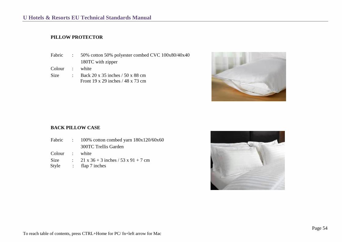
PILLOW PROTECTOR
Fabric : 50% cotton 50% polyester combed CVC 100x80/40x40
180TC with zipper
Colour : white
Size : Back 20 x 35 inches / 50 x 88 cm
Front 19 x 29 inches / 48 x 73 cm
BACK PILLOW CASE
Fabric : 100% cotton combed yarn 180x120/60x60
300TC Trellis Garden
Colour : white
Size : 21 x 36 + 3 inches / 53 x 91 + 7 cm
Style : flap 7 inches

U Hotels & Resorts EU Technical Standards Manual
Page 55 To reach table of contents, press CTRL+Home for PC/ fn+left arrow for Mac
FRONT PILLOW CASE
Fabric : 100% cotton combed yarn 180x120/60x60
300TC Trellis Garden
Colour : white
Size : 20 x 30 inches / 50 x 76 cm
Style : flap 6 inches
DUVET
Fabric : 100% cotton 233TC down proof with self-piping
Colour : white
Size : King 270 x 235 mm
Twin 180 x 235 mm
Filling : 40% white duck down
60% white duck feather
Weight : King 870 g
Twin 635 g

U Hotels & Resorts EU Technical Standards Manual
Page 56 To reach table of contents, press CTRL+Home for PC/ fn+left arrow for Mac
DUVET COVER
Fabric : 100% cotton combed yarn 300TC Trellis Garden
Colour : white
Size : King 275 x 240 cm
Twin 185 x 240 cm

U Hotels & Resorts EU Technical Standards Manual
Page 57 To reach table of contents, press CTRL+Home for PC/ fn+left arrow for Mac
Bedside Tables and Bed Heads
Each side of the king bed has a loose bedside table. Twin beds will have a central table between the two beds larger in length.
King bedside table min. (LxWxH cm) 50x40x55, depending on what will be placed on these tables: lamp, telephone, alarm clock, etc.
Twin bedside table min. (LxWxH cm) 70x40x55, depending on what will be placed on these tables: lamp, telephone, alarm clock, etc.
The height of the top surface of the side tables should be 5 cm lower than the mattress to make it impossible to knock against it.
The tables should allow room for the items such as books, keys, phone, glasses etc.
Bedside tables should have night lights mounted below which are individually wired to the bedside switch
The telephone is generally placed closest to the window table.
A shelf or a drawer should be provided, with ski-slope, easy slide castor and safety stop.
It is recommended that control panels are not built into the night table. This is only acceptable if the controls are easy to access and if they are
visible and accessible from a prone position.
The bed head must be designed for different sized beds and decor schemes.
The height must be such that it is impossible to bump one’s head on an edge. Bed height is 59.5 cm therefore the suggested height is approx. 120
cm min from floor to headboard edge.
The material must be easy to wash. (No fabric).
It is preferable to use built-in lighting to eliminate side table lamps.

U Hotels & Resorts EU Technical Standards Manual
Page 58 To reach table of contents, press CTRL+Home for PC/ fn+left arrow for Mac
Armchairs and Tables
A minimum of one armchair or one armchair and a small sofa if size permits.
With removable covers for easy cleaning or if fabric is used needs to be “Scotch Guard” treated.
There must be carpet gliders or felt stickers under the feet depending on the floor surface.
The seat height of the armchairs is approx. 45 cm.
Except for the sofa, upholstered armrests should not be used.
The foam used for the seats and cushions should be either latex or foam made without CFC-based expansion agents.
A side table allowing guests to take breakfast and dinner in their room (HxLxW cm) 54x70x50 or a minimum 65 cm in diameter.
If glass is used for the table top it must be non-reflective.
Desks and Chairs
The desk should measure at minimum (LxWxH cm) 140x60x75 only in business hotels and suites.
It should have a drawer large enough to contain office stationary for business hotels, minimum of 10 cm.
It should preferably be located near the window and should have enough area for a desk lamp to leave maximum workspace on the desk.
At desktop height, there shall be two spare international electrical outlets or one international outlet including two (2) USB chargers.
The desk should have a chair or a chair with arm rests low enough to slide under the top.
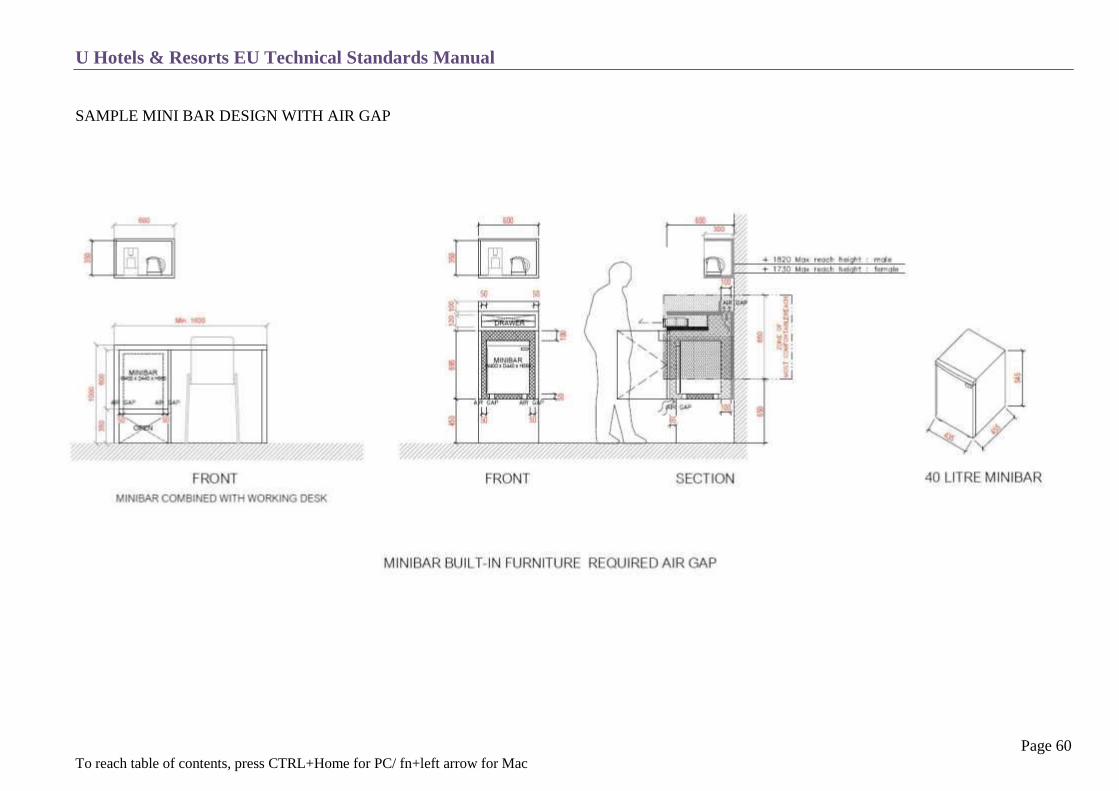
Mini-Bar
Absorption system (noiseless) – no compressors – automatic defrosting.
Minimum capacity 40 litres, external dimensions are approx. (W x D x H) 435 x 440 x 560 mm.
The refrigerator should be enclosed, however with good air circulation. The sides and the bottom free space between refrigerator and furniture
needs to be min. 5 cm, at the back of refrigerator it requires a min. 10 cm. The furniture should have a vent to release hot air which should be hidden
and not obvious on top of the furniture.
Located either in the closet under the TV or next to the seating area. Glass-fronts are possible, where adapted to the decor.
Including cabinet, shelves or drawer for the list below :
o Standard Room
1 Capsule coffee machine
4 Coffee capsules
1 Water kettle

U Hotels & Resorts EU Technical Standards Manual
Page 59 To reach table of contents, press CTRL+Home for PC/ fn+left arrow for Mac
2 Cappuccino cups with saucers
2 Coffee spoons
2 High ball glasses (Mini bar)
2 Whiskey Tumbler (bathroom)
Condiments include tea, sugar/crème and snacks
Tissue box with tissues
o Suite Room
1 Capsule coffee machine
4 Coffee capsules
1 Water kettle
2 Madison red wine glasses
2 High ball glasses (Mini bar)
2 Whiskey Tumbler (bathroom)
2 Coffee spoons
2 Teaspoons
2 Cappuccino cups with saucers
2 Espresso cups with saucers
Condiments include tea, sugar/crème and snack
Tissue box with tissues
U Hotels & Resorts EU Technical Standards Manual
Page 60 To reach table of contents, press CTRL+Home for PC/ fn+left arrow for Mac
SAMPLE MINI BAR DESIGN WITH AIR GAP

U Hotels & Resorts EU Technical Standards Manual
Page 61 To reach table of contents, press CTRL+Home for PC/ fn+left arrow for Mac
SAMPLE MINI BAR TRAY ARRANGE MENT

U Hotels & Resorts EU Technical Standards Manual
Page 62 To reach table of contents, press CTRL+Home for PC/ fn+left arrow for Mac
TV Cabinet
The cabinet, which can also hold the mini-bar, is an important decorative element and must be treated as such.
Where there is limited space built-in wall units are preferable in order to conceal cabling at the back of TV but the cabling should be easy to access.

U Hotels & Resorts EU Technical Standards Manual
Page 63 To reach table of contents, press CTRL+Home for PC/ fn+left arrow for Mac
Mirrors
There should be a full-length mirror near the closet and/or the bathroom door with a minimum size of (HxW cm) 140x45.
The mirror should be well lit (250 to 300 Lux).
Other decorative mirrors may also be placed in the room.
The mirrors must have a frame or bevelled edges.
Decorative Items
There should be at least two pieces of artwork or a backdrop per room, correctly hung and well lit.
The light illumination for the artwork may be one of the ambient lighting therefore controlled by the two-way switch.
The artwork must be hung in such a way that the guest may not remove them.
Also loose items for decoration can be added to make the room feel warm (it is suggested to have some budget available to decorate the hotel)
Balcony (if applicable)
The balcony equipment depends on the size. At a minimum there should be two armchairs with removable cushions and a table.
Outside furniture should be used, preferably in natural hard wood or cast iron (no plastic, resin, or painted wood).
Lighting fixtures for the balcony need to blend into the overall façade lighting.
Operating Equipment
For all equipment such as pillows, duvets etc., refer to the hotel’s dedicated OPE list

U Hotels & Resorts EU Technical Standards Manual
Page 64 To reach table of contents, press CTRL+Home for PC/ fn+left arrow for Mac

U Hotels & Resorts EU Technical Standards Manual
Page 65 To reach table of contents, press CTRL+Home for PC/ fn+left arrow for Mac
BATHROOM
Concept
Fixtures
Electricity and Low Voltage
Coverings
Accessories
Towels

U Hotels & Resorts EU Technical Standards Manual
Page 66 To reach table of contents, press CTRL+Home for PC/ fn+left arrow for Mac
CONCEPT
The bathroom should never be smaller than 8 m2 and dark colour schemes should be avoided, except if the bathroom has dedicated lighting.
It is important to achieve a uniform look between the floor, walls and ceiling, which need to be in harmony with the rest of the room’s décor.
The bathroom shall be one of the areas worked on by the Interior Designer.

U Hotels & Resorts EU Technical Standards Manual
Page 67 To reach table of contents, press CTRL+Home for PC/ fn+left arrow for Mac
FIXTURES
Toilet compartmentalized with a minimum (WxL cm) 100x110.
Compartment door has a preferred minimum width of 70 cm.
If there are space constraints, provide a toilet alcove that is not within view of the bathroom entry.
Provide one wall-hung or floor-mounted water closet with low-water consumption and quiet flush design.
Avoid placing the toilet directly in front of the entry door. It can also be in a separate room (as per the Hotel Brief).
1 Vanity/washbasin unit with a glass, marble or stone top and ledge positioned 85 cm from the ground.
Minimum length of 140 cm with a minimum drop facing of 25 cm.
The vitreous china sink is mounted under the top so that the joint is not visible and the overflow is located opposite the mirror side.
Sinks placed on the vanity counter should not exceed a height of 90 cm. Vanity counter level should be between 60 and 70 cm.
A mirror needs to be placed on a strip min. 10 cm above the vanity unit.
Detached from the wall to provide back ventilation (could be LED backlit for a better atmosphere).
Shower cubical with a minimum size of (WxL cm) 100×120 with an anti-slip floor.
Cubical door with a preferred minimum width of 70 cm.
Minimum of 2 cm recess / threshold into the cubical. Ratio of fall towards trap is between 1:60 and 1:80.
The shower trap must absorb twice the shower in-flow to prevent overflows.
Bench/footrest at a height of 45 cm.
Security or triplex glass (laminated) door not reaching the ceiling, maintaining a gap of 20 cm to the ceiling.
No plastic, wood or aluminium can be used for the cabin frame.
Rain shower head concealed into the ceiling or wall mounted with a minimum rain shower head size of 8 inches or 20 cm, positioned a minimum
210 cm from the bottom.
Hand held shower with 1.20 m long hose attached to the wall with an adjustable flow bar, positioned at least 190 cm from the bottom.
All the fixtures shall be stainless steel and equipped with 3-hole high quality mixer-faucets, sound-rated and with colour-coding (Gröhe or similar).
The bath, basin and bidet are equipped with pop-up waste facilities.
Ventilation: the extraction vents shall be installed above the toilet bowl and the shower if the WC is separate. Flows shall be carefully studied to
avoid any fogging of the mirror.
The bathroom door shall allow the necessary air flow from the bedroom. It shall be equipped with an inside lock and can be unlocked from the
outside in case of emergencies. The same applies to the WC (if separate).

U Hotels & Resorts EU Technical Standards Manual
Page 68 To reach table of contents, press CTRL+Home for PC/ fn+left arrow for Mac
ELECTRICITY AND LOW VOLTAGE
All electrical devices and lighting fixtures must be located at a horizontal distance of more than 60 cm from the shower.
Fixtures or outlets fitted around the shower area at not than less 225 cm, from the floor and 60 cm from the unit must be special low-voltage fixtures
or watertight fixtures with a double insulation.
Accent lighting shall be provided in front of the mirror at face height and a level of 400 lux.
Adequate levels must be provided around all the other fixtures of about 250 to 300 lux.
Backup light shall be separate from the mirror lighting. All light fixtures require plastic protection sheets if mounted into the ceiling.
Provide a 110/220 volt razor outlet for international plug use.
All the electrical equipment must be protected by a differential circuit breaker of 30 mA. The main metal fixtures shall be connected by
equipotential coupling and be grounded.
Magnifying mirror on a bracket wall-mounted close to the vanity unit.
A speaker minimum 6 W connected to the bedroom T.V. and sound system with volume control.
Phone with on-hook connection (same line as the main bedroom extension), accessible from the toilet at a height of 135 cm from the floor. This can
be optional due to nowadays extensive private mobile usage.

U Hotels & Resorts EU Technical Standards Manual
Page 69 To reach table of contents, press CTRL+Home for PC/ fn+left arrow for Mac
COVERINGS
Floors
Decorative tiles, stone or marble semi-gloss or non-slip finish, providing sound insulation to not disturb the rooms on lower floors.
Waterproofing for wet areas:
o at least 10 cm over the hob or step down onto the bathroom floor should be waterproofed
o at least 15 cm up the walls inside the shower walls needs to be waterproofed
o the vertical angle between any two walls in the shower needs to be waterproofed up to at least 180 cm high
o the entire bathroom floor needs to be waterproofed if hard-wood flooring
Terrazzo, carpets, plywood or pressed wood are excluded
Install a floor drain only when required by regulations in leisure hotels or those with a Japanese clientele. (The shower drain can also be
used for that purpose). In that case, the bathroom floor must be fully waterproofed.
Sharp edges must be avoided or guarded or rounded if present.
Walls
Decorative tiles, stone, marble and glass/mirror on all walls, as well as under the sink along with decorative elements.
Sharp edges must be avoided or guarded or rounded if present.
Glass will need to be laminated.
Ceilings
Green board (green dry wall) for damp conditions, humidity and the occasional minor splashes of water.
It is recommended to have cove ceilings with indirect lighting with the least number of down light fixtures possible.
Access holes require aluminium frames.
If the fan coil unit is located in the bathroom, a large enough access hatch needs to be provided (min. 80 x 50 cm).

U Hotels & Resorts EU Technical Standards Manual
Page 70 To reach table of contents, press CTRL+Home for PC/ fn+left arrow for Mac
ACCESSORIES
Shaving mirror, as listed above.
Toilet paper roll dispenser.
Towel rack for 4 towels below the vanity counter.
Sanitary hose on guest’s right side, next to the toilet
Towel bar on the shower door outside of the cubical. (Door handle and towel bar should be one piece).
Small towel bar at vanity counter, mounted below the counter.
A hook for sanitary disposal bags near the toilet bowl (or given with the amenities on the tray).
A double or triple robe-hook.
Retractable clothes line or fixture to dry clothing.
Waste bin below vanity counter or adjacent to the toilet.
All accessories should have the same finish as the faucets.
For all unattached accessories (stool, soap dish, wastebasket, scale, tissue box etc.) see OPE listing.
For special accessories see Chapter C 23, the Disabled.
Towels
SIZE
(inch)
WEIGHT
(lbs =12 pcs)
SPEC DESIGN COLOUR
Face towel 12 12 1.5 100% Cotton 20/2 Double loop White
Hand towel 16 32 4 100% Cotton 20/2 Double loop White
Bath towel 40 60 24.5 100% Cotton 20/2 Double loop White
Pool towel 40 80 28 100% Cotton 20/2 Double loop Coloured, as per hotel theme
Shower mat 20 30 10 100% Cotton 20/2 Double loop White

U Hotels & Resorts EU Technical Standards Manual
Page 71 To reach table of contents, press CTRL+Home for PC/ fn+left arrow for Mac
SAMPLE BATHROOM ELEVATION

U Hotels & Resorts EU Technical Standards Manual
Page 72 To reach table of contents, press CTRL+Home for PC/ fn+left arrow for Mac
SUITES
Distribution and Location
U Hotels & Resorts Suites
U Hotels & Resorts EU Technical Standards Manual
Page 73 To reach table of contents, press CTRL+Home for PC/ fn+left arrow for Mac
DISTRIBUTION AND LOCATION
The distribution shall be based on the Hotel Brief. Suites are usually located on floors which offer the best view.
U HOTELS & RESORTS SUITES (2 room modules for one key)
Should include:
A large bedroom with bathroom and dressing room within one bay.
A sitting room/dining room with office corner within one bay.
An entrance from the corridor leading to the sitting room bay.
A toilet room with vanity unit next to the entrance.
A twin bedroom that can be connected to the suite at the sitting area with a connecting door or via the balcony (rentable separately as a lock off).

U Hotels & Resorts EU Technical Standards Manual
Page 74 To reach table of contents, press CTRL+Home for PC/ fn+left arrow for Mac
CORRIDORS
Elevator Landings
Corridors
Housekeeping Pantries

U Hotels & Resorts EU Technical Standards Manual
Page 75 To reach table of contents, press CTRL+Home for PC/ fn+left arrow for Mac
ELEVATOR LANDINGS
Wide enough with a minimum of 250 cm and separate from the rest of the corridors.
Include an in-house telephone with a direct connection to operator on off-hook within the lift landing area.
LCD TV panel for hotel information (business hotels only).
The decor should include plants, waiting areas with armchairs, mirrors, antique furniture, paintings or lithographs.
The ceiling and walls should be given special attention to make the guest forget about the waiting time.
Elevator doors should be graffiti proof.
Natural lighting wherever possible.

U Hotels & Resorts EU Technical Standards Manual
Page 76 To reach table of contents, press CTRL+Home for PC/ fn+left arrow for Mac
CORRIDORS
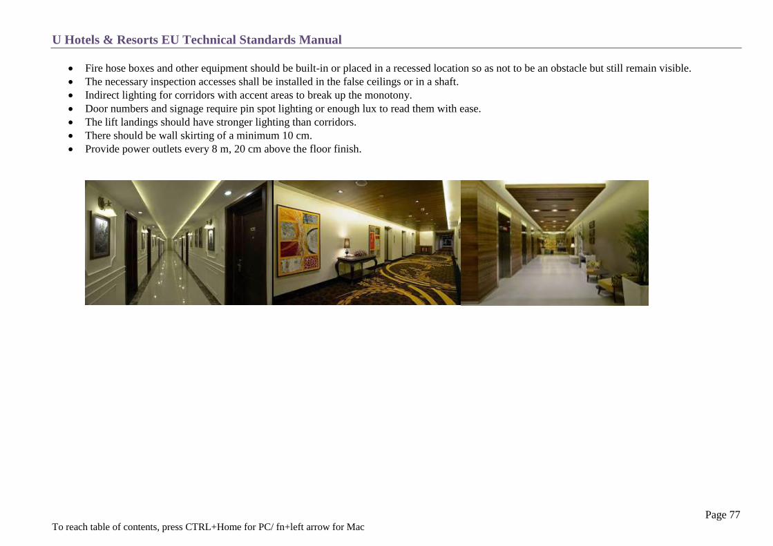
The corridors do not only connect the guestrooms to the rest of the hotel but are also a statement of the hotel’s personality. This personality is usually
expressed in terms of decorations and special provisions must be arranged in advance. This may consist of varied ceiling heights, lighting effects,
doorways for each guestroom, top quality wall coverings, carpets with special designs and different colours and interesting floor themes.
SAMPLE CORRIDOR ELEVATION
Double corridors with a minimum width of 180 cm (single corridors 160 cm).
Ceiling height with a minimum of 240 cm.
Strategic locations like elevator landings and housekeeping pantry doors must utilize subtle corner and wall guards to protect against trolleys etc.
Design of signage (see chapter C-22 Signage and the Corporate Identity Manual).
Service shaft doors should be mounted on hidden hinges and could be disguised as picture frames or similar to fit into the corridor to have the
traditional shaft doors removed.
Shafts, due to fire-safety, must be plugged at each flooring level and provide a pipe sleeve for each pipe.
Up to 90 cm from floor should be of a solid material, protruding min. 2.5 cm from wall finish to protect the surface. Stone, wood, and stainless are
recommended.
U Hotels & Resorts EU Technical Standards Manual
Page 77 To reach table of contents, press CTRL+Home for PC/ fn+left arrow for Mac
Fire hose boxes and other equipment should be built-in or placed in a recessed location so as not to be an obstacle but still remain visible.
The necessary inspection accesses shall be installed in the false ceilings or in a shaft.
Indirect lighting for corridors with accent areas to break up the monotony.
Door numbers and signage require pin spot lighting or enough lux to read them with ease.
The lift landings should have stronger lighting than corridors.
There should be wall skirting of a minimum 10 cm.
Provide power outlets every 8 m, 20 cm above the floor finish.

U Hotels & Resorts EU Technical Standards Manual
Page 78 To reach table of contents, press CTRL+Home for PC/ fn+left arrow for Mac
HOUSEKEEPING PANTRIES
Each block, cluster or floor should have a pantry, accessible from the guestroom corridor and service elevator landing if applicable.
Located in front of the elevator and provide at least a width of 250 cm with access to the emergency stairway. The service elevator landing should
always be lit.
Provide a door closer, door stopper, corner and door guards and floor number plates (on the landing and in the stairway).
Each pantry area should have power outlets and one wall mounted telephone, located close to the elevator.
The pantry should include:
o Linen room, with closets or a separate area for supplies with shelving, that can be locked plus a linen storage area and space to store
housekeeping baskets or trolleys (For 25-30 rooms = about 15 m²).
o A water station (for bucket) and single service sink (hot and cold water).
o WC for the employees (accessible from the service elevator landing on every other floor).
o Access to the linen chute, if any.
o Ice machine on every other floor.

U Hotels & Resorts EU Technical Standards Manual
Page 79 To reach table of contents, press CTRL+Home for PC/ fn+left arrow for Mac
SURROUNDINGS DESIGN
Concept
Pedestrian and Vehicle Traffic
Parking
Exterior Lighting
Landscaping

U Hotels & Resorts EU Technical Standards Manual
Page 80 To reach table of contents, press CTRL+Home for PC/ fn+left arrow for Mac
CONCEPT
When approaching the hotel, the surroundings must convey a feeling of warmth and welcome. The façade along with the hotel signage is an integral part of the entrance.
The façade should be accentuated by special lighting and landscaped decorations.
Directional signs should be located at strategic locations to emphasize the hotel’s facilities (see chapter C-22 Signage).
The exterior areas should be located so to not to disturb the interior area with noise, lighting or disturbances, whether the interior is for relaxed or
linked to a special zone such as a nightclub.
In city hotels a possible link between the hotel and the city can be via an exterior restaurant with a terrace. This terrace can be protected with
screens of vegetation or by a transparent enclosure such as a veranda.
For leisure hotels, the garden and swimming pool must be the focal point of the architectural concept towards which all the public areas converge.
PEDESTRIAN AND VEHICLE TRAFFIC
Pedestrian and vehicle traffic must be separate and all abrupt crossings avoided. Space must be provided for a waiting area.
Provide 2 lanes of automobile traffic in front of the entrance with each lane about 3 meters wide.
o 1 lane for waiting automobiles
o 1 passing lane
The road surface design in front of the main hotel entrance should be iconic with a pattern of interlocking stone paving or other neat looking floor
finishes.
U Hotels & Resorts EU Technical Standards Manual
Page 81 To reach table of contents, press CTRL+Home for PC/ fn+left arrow for Mac
PARKING
The parking area should be in a shaded area if possible and within a short distance of the hotel area without obstacles to cross and in keeping with
the aesthetics of the surroundings.
A water tap and drain should be provided in an area where it will also be possible to wash cars but out of sight of the lobby.
In order to avoid large spans of asphalt, the use of an “evergreen” pavement should be studied, involving the installation of grassy areas.
Where underground parking areas are used, they shall be equipped with a water tap, water drainage for car-washing (as above), and road gutters at
the entry point and the foot of the ramps as well as including necessary ventilation.
Access to the hotel shall be controlled (guard rooms, automatic barriers, CCTV, and intercom link to the reception).
Directional signage for pedestrians and vehicles shall indicate the floor levels and painted lines shall be used to separate parking spaces.
Signs directing pedestrians toward the hotel entrance should be designed to present a visual image of quality.
In areas accessible to guests, paint, bright lighting, colours and other design features shall be used in order to avoid any gloomy or insecure feeling.
Where there is valet parking and the hotel has more than 80 rooms, a driver’s lounge will be provided. It will include an intercom connection with
the main entrance parking desk, a T.V., toilets and chairs.
In certain circumstances a sleeping room with wet facilities should be provided for drivers. This is for remote hotel locations or if a limousine
company is engaged for the services.

U Hotels & Resorts EU Technical Standards Manual
82 To reach table of contents, press CTRL+Home for PC/ fn+left arrow for Mac
EXTERIOR LIGHTING
Night lighting shall be designed as part of the landscaping, where the vegetation provides an illuminated route through which the guest moves.
Directional spotlights should be used more often than luminous bollards and lampposts.
The exterior lighting shall have the functions listed below, in the form of the corresponding circuits:
Roadways and parking areas lit by lampposts; a lamp height not less than 3m above ground.
Decorative lighting for gardens, flower beds, bushes and spotlights for fountains.
Floodlighting of the facades (glare from the facade lighting must not disturb guest’s comfort in the rooms).
Sign lighting.
These circuits shall be controlled:
Automatically by timers. Each circuit must be programmable for different hours and scenes.
Manually from an electrical switchboard located in the reception area or control room.
Several electrical networks shall be provided for:
Watertight outlets.
Swimming pool.
Reduced garden lighting.
Activities.
Actual exterior lighting.
Heavy duty power supply circuits for outside functions in the resorts gardens e.g. buffets, shall be installed at strategic points.
In the activity areas, installation shall include watertight distribution boxes containing power outlets fixed to a concrete base. They shall be
operated from the control panel. The installation shall be completed by standby terminals on circuit breakers on electrical switchboards adjacent
to these areas.
Swimming pool lighting shall use 12 volts and be controlled from a separate control panel or control room.
These swimming pool spotlights should be removable.
The lighting fittings shall be selected based on the decoration project, keeping energy saving in mind.
U Hotels & Resorts EU Technical Standards Manual
83 To reach table of contents, press CTRL+Home for PC/ fn+left arrow for Mac
LANDSCAPING
It is advisable to call upon a landscape architect with a good knowledge of local vegetation to make an overall study of the exterior and interior
landscaping.
Existing trees should be kept for maximum integration with the surroundings and landscaping whenever a green field site is planned.
An automatic sprinkler system and draw-off taps should be installed where needed.
Topsoil, trees and plants should be added in sufficient size and quantity to create a greenery ambience as soon as the hotel is nearing opening.
Inside the hotel, it is preferable to group plants as accents rather than in dispersed pots. They should be placed in planters integrated with the
architecture and decoration. Those should be fitted in consideration with:
o Waterproofing
o Drainage
o Watering facilities
In a resort hotel, landscaping quality is as important as the architecture. Consequently, the landscape architect must work together with the
building architect in establishing the design, and he should participate in final realization of the layout drawings.
Swimming pool surroundings as well as beach layout and access to the sea, shall be integrated into this study if necessary.
A complete drainage system must allow quick evacuation of excess rainwater, especially in all accessible areas such as parking, walkways, and
sports areas etc. (see Chapter T8 Sanitary Plumbing).
U Hotels & Resorts EU Technical Standards Manual
84 To reach table of contents, press CTRL+Home for PC/ fn+left arrow for Mac
RECEPTION
Entrance
Lobby
Guest Reception
Front Desk
Front Office Back of House
Schematic Layout

U Hotels & Resorts EU Technical Standards Manual
85 To reach table of contents, press CTRL+Home for PC/ fn+left arrow for Mac
ENTRANCE
Architecture – Decor
The hotel must have street frontage in accordance with its stature and importance.
The entrance faces the main access road.
Clearly and immediately visible and identifiable.
Consider elevated entrances.
Maintain accessibility.
Direct visual and pedestrian contact with the hotel’s setting.
Consider traffic and pedestrian flow.
Always use clear glass in this area.
Consideration of the quality of the materials, night lighting and signage all contribute to the U Hotels & Resorts specific appearance effort.
The layout will allow through-views to the outside and views of the landscape and the surroundings from the lobby entrance especially at resort
hotels.
Awning / Canopy
The awning, porch or canopy is an important architectural element which marks the entrance.
Needs to cover the road access (minimum 2 lanes).
Protection against rain with sufficient cutter capacity to ensure no overflow.
Well-lit at night.
If necessary, provide a bell (luggage), taxi and/or valet driver desk with telephones for hotels above 80 keys.

U Hotels & Resorts EU Technical Standards Manual
86 To reach table of contents, press CTRL+Home for PC/ fn+left arrow for Mac
LOBBY
Decor – Architecture
The lobby and reception area must be adjacent to the entrance and on the same level.
It must create a warm welcoming feeling for its guests. U Hotels & Resorts does not want to create a “monumental” feeling.
The decor emphasizes open spaces and views of the outside with as few obstacles as possible such as voluminous curtains, very low ceilings or
hand rails.
The overall character is provided by using a few items of quality, such as local craftwork or original artworks and furniture.
If water features are available, they shall be studied and calculated in terms of aesthetics, noise, spray pattern (diameter), lighting, pumps,
balance tank etc.
Avoid using dark colours.
Look for quality materials which are to be highlighted with natural lighting whenever possible.
Artificial lighting should only be used to indicate circulations and signage as well as create decorative and functional accents.
The lighting should be split into several circuits, all controlled by dimmers with 3 to 4 settings. The dimmer controls and other circuits, as well
as the following commands, are all located in the back of house of the reception area:
Provide 10/16 A+E power outlets 20 cm above the floor after every 750 cm around the public areas and adjacent hallways.

U Hotels & Resorts EU Technical Standards Manual
87 To reach table of contents, press CTRL+Home for PC/ fn+left arrow for Mac
GUEST RECEPTION
Purpose
The Lobby has two functions. These functions can be separated if needed with the help of the elevators or a seating area located in between
these two locations.
o Reception Area
The front desk is the central point for all the hotel’s guest services.
Reception personnel must be able to see the arriving guest immediately.
Guest must be able to recognize the front desk without guidance.
The front desk should be a desk and not a counter which acts as a barrier.
Does not need to be in direct contact with the entrance and requires a free space between without obstacles.
The desk should have clear signage and well-arranged natural lighting if possible.
o Meeting, Information and Activity Point
The lobby is a starting point for all the services that enliven the hotel such as conference rooms, restaurants, bars, gardens and
leisure activities.
Acts as a meeting place & information area.
Includes a comfortable waiting area which could be connected with a lounge bar.
Avoid adding mezzanines that break the flow of circulation.
Keep high ceilings to give an overall spacious impression.
From initial design phase the internal signage needs to be given attention for guests arriving at the lobby and those exiting the
elevator.

U Hotels & Resorts EU Technical Standards Manual
88 To reach table of contents, press CTRL+Home for PC/ fn+left arrow for Mac
FRONT DESK (Guest Reception)
Needs to be visible and accessible from the main entrance without blocking the view of the lobby or hindering the transparent view from the entrance.
Front office desk requirements (in all cases):
Desk ;
o For sitting reception desk- L,W,H 300 x 90 x 74 cm per station with 4 chairs for guests & 2 chairs for employees.(1 station
accommodate 2 employees)
o For standing reception desk - L,W,H 230 x 90 x 74 cm per station (1 station accommodates 2 employees)
One computer notebook or very slick designed screens with wireless mouse and keyboard computers per station connected with LAN.
Provide filing slots, printer, guest key card encoder, key rack, credit card terminal, and passport scanner for each station below the desk. Digital telephone.
UPS (power back up for computers if a desktop version is chosen.)
7 double sockets for all gadgets.
2 telephone lines (telephone & credit card terminal)
4 LAN connections (CAT 6)

U Hotels & Resorts EU Technical Standards Manual
89 To reach table of contents, press CTRL+Home for PC/ fn+left arrow for Mac
FRONT DESK – SITTING STYLE

U Hotels & Resorts EU Technical Standards Manual
90 To reach table of contents, press CTRL+Home for PC/ fn+left arrow for Mac
FRONT DESK – SITTING STYLE
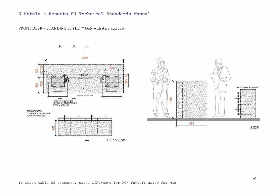
U Hotels & Resorts EU Technical Standards Manual
91 To reach table of contents, press CTRL+Home for PC/ fn+left arrow for Mac
FRONT DESK – STANDING STYLE (* Only with AHS approval)

U Hotels & Resorts EU Technical Standards Manual
92 To reach table of contents, press CTRL+Home for PC/ fn+left arrow for Mac
FRONT DESK – STANDING STYLE (* Only with AHS approval)

U Hotels & Resorts EU Technical Standards Manual
93 To reach table of contents, press CTRL+Home for PC/ fn+left arrow for Mac
Bellboy Station (if required):
With a view of or at the entrance.
These areas do not need specific signage.
They must be distinguishable by their personality and décor.
Requires a telephone.
Two-way speaker system to the drivers’ room (if available).
Close access to the luggage room.

U Hotels & Resorts EU Technical Standards Manual
94 To reach table of contents, press CTRL+Home for PC/ fn+left arrow for Mac
FRONT OFFICE (BACK OF HOUSE)
Located behind the reception desks and hidden away and inaccessible to the guests, these areas include:
Open office for the front office team with shared working stations.
Each station requires a computer terminal (100 key hotels require 2 work stations).
Reservation stations (100 key hotels require 2 work stations).
Each station comprises of a desktop computer with UPS power back up, connected to a LAN line, and a telephone.
Private office cubical for the Front Office Manager (minimum 7 m2).
A luggage room, with:
o Secured access.
o Possible access from the Port Cochere and leading to the service elevator.
o Luggage and cart storage area.
o A whiteboard.

U Hotels & Resorts EU Technical Standards Manual
95 To reach table of contents, press CTRL+Home for PC/ fn+left arrow for Mac
SCHEMATIC LAYOUT
Front Office Back of House (small hotel)

U Hotels & Resorts EU Technical Standards Manual
96 To reach table of contents, press CTRL+Home for PC/ fn+left arrow for Mac
SCHEMATIC LAYOUT
Front Office Back of House (large hotel)

U Hotels & Resorts EU Technical Standards Manual
97 To reach table of contents, press CTRL+Home for PC/ fn+left arrow for Mac
PUBLIC CORRIDORS & SHOPS
Concept
Lifts
Stairways for Public Areas
Toilets
Shopping Area
Concession Shops
U Hotel & Resorts Boutiques
U Hotels & Resorts EU Technical Standards Manual
98 To reach table of contents, press CTRL+Home for PC/ fn+left arrow for Mac
CONCEPT
Operating principles:
Corridors and passageways branching off the main lobby must be designed to allow the guest to quickly understand the hotel layout.
Must have unity in style and décor.
Should follow the overall concept of interior design linking the public areas with the guest rooms.
Provide rooms for storage of maintenance materials, thoughtfully distributed and equipped with water supply and drainage.
Wall finishes need to be durable with solid materials such as stone, concrete etc. especially from floor level up to 0.90 m. to prevent the wall
from scratches. Wallpaper is not recommended.
Equipment:
The use of skylights should be avoided and indirect lighting be used instead.
Lighting of decorative elements and/or of ceilings is preferred.
Provide power outlets within the corridors every 750 cm, and 20 cm above the floor, including store rooms.
Shaft access sizes should be minimized to small doors and operate like a window.
Shafts between floors should be closed off with steel plates or filled with concrete.
Doors:
They must be sturdy and able to withstand intensive use.
Must be fire-rated for 90 minutes.
Acoustic proof.
Electronic locks are required and systems with RFID are preferred. Those locks should be used for all types of doors and not only guest room
doors, to manage and control work flow.
U Hotels & Resorts EU Technical Standards Manual
99 To reach table of contents, press CTRL+Home for PC/ fn+left arrow for Mac
ELEVATORS (LIFTS)
The elevator bank must be visible from the reception area.
When guests come down from their rooms, they must see the lobby and find easy the directions to hotel facilities.
As elevator cars are confined spaces and can be claustrophobic to certain guests though this can be remedied through:
o Wall coverings with special decorations.
o Active areas like TV screens with advertising or information.
o Glass walls may be used to give a view of the outside.
The coverings and doors must be made from materials resistant to shock, tearing and graffiti.
The button panel should be easy to read and list the main functions of the different floors (see chapter T15- Lifts).
The interior designer shall determine how they are to be handled (see chapter C-22 Signage).
The landings must include furniture and decorations.
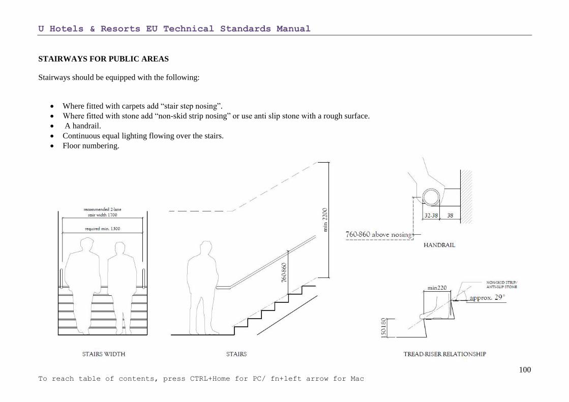
U Hotels & Resorts EU Technical Standards Manual
100 To reach table of contents, press CTRL+Home for PC/ fn+left arrow for Mac
STAIRWAYS FOR PUBLIC AREAS
Stairways should be equipped with the following:
Where fitted with carpets add “stair step nosing”.
Where fitted with stone add “non-skid strip nosing” or use anti slip stone with a rough surface.
A handrail.
Continuous equal lighting flowing over the stairs.
Floor numbering.

U Hotels & Resorts EU Technical Standards Manual
101 To reach table of contents, press CTRL+Home for PC/ fn+left arrow for Mac
TOILETS
Organisation:
Toilets should be located near the lobby, restaurants, and conference and administration rooms and by other facilities as required. Toilets must not
open directly into the restaurants and bars or public areas under any circumstances.
Men’s and women’s toilets must be separate, even if they have a common entrance.
They should each have a vestibule or zigzag access.
The direction in which the doors swing open should be studied in relation to the viewing angles.
Compartments should be enclosed, have locks and be ventilated as per the below dimensions.
Privacy panels between the urinals (partition).
A toilet for the disabled should be provided for the main lobby and conference rooms (see chapter C 23- The disabled for toilet layout).
A small cleaning closet should be provided for each floor in the public areas.

U Hotels & Resorts EU Technical Standards Manual
102 To reach table of contents, press CTRL+Home for PC/ fn+left arrow for Mac
SAMPLE DRAWING OF PUBLIC TOILET

U Hotels & Resorts EU Technical Standards Manual
103 To reach table of contents, press CTRL+Home for PC/ fn+left arrow for Mac
Decor
The decor must avoid looking “clinical”.
The qualitative aspect must be kept in mind. Make sure that materials and fittings used can be easily cleaned.

U Hotels & Resorts EU Technical Standards Manual
104 To reach table of contents, press CTRL+Home for PC/ fn+left arrow for Mac
Equipment and Accessories.
The following should be installed in each compartment:
Double toilet paper roll dispenser.
Sanitary hose, located on the right side of guests.
Drainage, located under the sanitary hose.
Garbage bin.
Clothes hook behind the door.
Sliding bolt with indicator which can be unlocked from the outside.
The following should be provided in the toilets:
One full-length mirror.
Hot air hand dryer or hand towel tray.
Soap dispenser for antibacterial hand soap.
Door closer for the toilet entrance door.
Disabled toilet for men and women at the lobby and conference area.
Mechanical ventilation.
Efficient deodorising system.
Automatically flushing urinals with either a timer or photoelectric cell.
Vanity area (women’s toilets).
U Hotels & Resorts EU Technical Standards Manual
105 To reach table of contents, press CTRL+Home for PC/ fn+left arrow for Mac
SHOPPING AREA (IF APPLICABLE)
Organisation:
The shops should never constitute a significant part of the hotels outside frontage.
They should be organised as a shopping arcade located near and visible from the lobby.
This area shall be one of the focal points of activity in the hotel.
In keeping with this feeling, the sterile, bland standardisation common to shopping malls is to be avoided.
Locations on the mezzanine, basement levels or in dead-ends are not recommended.
There are two types of shop: those operated under concession and those managed directly by U Hotels & Resorts.

U Hotels & Resorts EU Technical Standards Manual
106 To reach table of contents, press CTRL+Home for PC/ fn+left arrow for Mac
CONCESSION SHOPS
Depending on the situation, these shops can either be delivered to the concessionaires fully equipped and decorated (by the hotel interior designer), or
delivered as a shell with the technical elements for connection (electricity, telephone lines & LAN, plumbing, heating, ventilation), but without any
decoration. This part is then carried out by the tenant’s interior designer.
In both cases, the design must be approved by U Hotels and Resorts Management.
The type and number of shops is defined in the Hotel Brief.
Decor
Interior design and equipment, conducted by the tenants, (or their interior designer) must have prior approval from U Hotels and Resorts Management
and the hotel interior designer, who will remain in charge of decorating the shop front windows, protective grilles and signs.
Equipment
The following equipment is always part of the hotel general construction, not only of its shop fittings:
Plumbing, standby water supply, drainage, metering, central air conditioning.

U Hotels & Resorts EU Technical Standards Manual
107 To reach table of contents, press CTRL+Home for PC/ fn+left arrow for Mac
U HOTELS & RESORTS BOUTIQUES
Electrical distribution panel, metering, general circuit breaker
2 telephone lines, metering
Unfinished floor
Walls or partitions (undecorated)
Signage
Storage area, (delivered unfinished)

U Hotels & Resorts EU Technical Standards Manual
Page 108 To reach table of contents, press CTRL+Home for PC/ fn+left arrow for Mac
CUSTOMER SERVICES
Business Centre / Library
Swimming Pools
Ancillary Facilities
Fitness Centre
Spa & Wellness
Tennis Facilities

U Hotels & Resorts EU Technical Standards Manual
Page 109 To reach table of contents, press CTRL+Home for PC/ fn+left arrow for Mac
BUSINESS CENTRE / LIBRARY
Depending on the market and guest expectations, business hotels and city hotels will have separate business centres; however resorts will feature areas
called libraries where guests can check their personal emails or just sit and read a book. For smaller properties, the library can be combined with the lounge
bar.
General Organisation
The Business Centre/Libraries should be well located and visible from the hotel lobby or the hotel main corridors if possible.
This area should include:
A sign outside the room displaying opening hours.
A hostess desk, cabinet, locker with space for a computer with modem, work processor, spread sheet and printer (connected to the LAN).
A secretariat area with shelves for documentation.
A fax, photocopier, telephone and conveniently placed clock (business hotels only).
Office supplies and equipment conforming to the OPE list.
Comfortable armchairs or couches, a low table, floor lamps and two desks with two laptops or large sized tablets which are connected to the WIFI
system and connected to a central printer.
Smaller hotels can incorporate the library into the lobby lounge, which accommodates book shelves and has terminals to access the internet for free.

U Hotels & Resorts EU Technical Standards Manual
Page 110 To reach table of contents, press CTRL+Home for PC/ fn+left arrow for Mac
SWIMMING POOLS
General Concept
In all cases, the swimming pool must conform to local technical and safety regulations (notably depth marking, life safety equipment, presence of a
lifeguard, push-button alarms and pump switch-off, separate instruction panels for warnings and rules (large letters), etc.).
The shape of the pool is not restricted and the rules are only limited by imagination and originality. Thus, round or rectangular swimming pools
rarely correspond to these criteria and are not desirable.
It is preferable for the swimming pools to be designed with skimming or overflowing water i.e. infinity edge.
Access to the pool should be as direct as possible to avoid crossing the hotel lobby.
Wherever possible, swimming pools should be located on the ground floor in contact with the rest of the site rather than on terraces.
The swimming pool area should be protected from strong winds.
Pool dimensions depend on the Hotel Brief and should be adapted to the possibilities of the site. In all cases, it should provide a clear length of
around 25 m.
Pool surroundings should be at least twice the area of the pool. This space should have enough room for sunbathers and the installation of
umbrellas and tables with enough clearance for traffic.
Provide plants and landscaping around the pool surroundings, and create several “natural” areas for more privacy.
U Hotels & Resorts EU Technical Standards Manual
Page 111 To reach table of contents, press CTRL+Home for PC/ fn+left arrow for Mac
The buildings should not shade the swimming pool (study cast shadows according to latitude and to Northern or Southern hemispheres). However,
some shaded areas are required close by. When creating shaded areas with vegetation, avoid using deciduous trees near the swimming pool.
In all cases, the swimming pool should have a shallow and deep end and a separate pool for children (maximum depth 30 cm). The layout of this
pool should be designed for safety (barriers) and easy surveillance, while limiting the amount of noise.
Access to the pools shall be through full-sized steps with handrails rather than ladders.
The shallowest part of the main pool shall be at least 1.20 m deep.
The deepest point of the main pool should be at least 1.40 m deep.
Slopes in the area around the pool and a drainage system should prevent rainwater from running into the pool.
Resort Hotel Swimming Pools
In a resort hotel, the recreational character of the pool should be accentuated with “extras” such as waterfalls, whirlpools, Jacuzzi, slides etc.
The landscaping should be abundant and closely linked to the water theme: small islands with grass and plants or rocky borders with small
waterfalls into the main pool for example.
At the seaside, an overflowing type swimming pool gives a very strong visual connection between the pool and ocean.
Consider providing a small pool for children in a shaded, protected and fenced (>1m) area if the hotel is targeting families.
The pool surroundings should be large enough and well equipped to accommodate all of the hotel guests, keeping in mind that a person on a sun
lounger takes up 2m².
It is preferable for guests on sun loungers to looking at the pool and ocean view (if applicable) and to face the sun. Nevertheless, it is necessary to
provide some shaded areas around the pool zone.
The swimming pool should be close to the restaurants and bars; it creates an environment where everyone can see or be seen and increases business
at the sales outlets. However, its location must also be carefully studied in order to avoid noise nuisances to rooms.
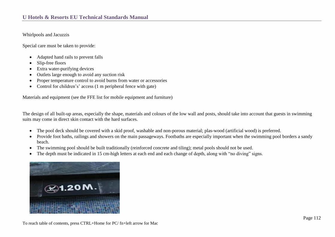
U Hotels & Resorts EU Technical Standards Manual
Page 112 To reach table of contents, press CTRL+Home for PC/ fn+left arrow for Mac
Whirlpools and Jacuzzis
Special care must be taken to provide:
Adapted hand rails to prevent falls
Slip-free floors
Extra water-purifying devices
Outlets large enough to avoid any suction risk
Proper temperature control to avoid burns from water or accessories
Control for children’s’ access (1 m peripheral fence with gate)
Materials and equipment (see the FFE list for mobile equipment and furniture)
The design of all built-up areas, especially the shape, materials and colours of the low wall and posts, should take into account that guests in swimming
suits may come in direct skin contact with the hard surfaces.
The pool deck should be covered with a skid proof, washable and non-porous material; plas-wood (artificial wood) is preferred.
Provide foot baths, railings and showers on the main passageways. Footbaths are especially important when the swimming pool borders a sandy
beach.
The swimming pool should be built traditionally (reinforced concrete and tiling); metal pools should not be used.
The depth must be indicated in 15 cm-high letters at each end and each change of depth, along with “no diving” signs.

U Hotels & Resorts EU Technical Standards Manual
Page 113 To reach table of contents, press CTRL+Home for PC/ fn+left arrow for Mac
Diving boards should be avoided for safety purposes.
The pool should be equipped with 12 V underwater lighting. It should be removable and have enough cable to rest the spotlights on the edge of the
pool for maintenance.
The pool surroundings and direct environment should be attractively and practically lit at night. Provide power outlets conforming to regulations for
entertainment activities.
The pool surroundings should be built with a slope to drain off rainwater.
The pool’s bottom tiling may include a decorative design (no logos) which may be reproduced on the pool decks.
See chapter T-8 Plumbing for the pool’s water treatment.
Water in the pools should only circulate through overflow gutters; the level of the water is then flush with the pool edges.
The drainage and filtering outlets shall be planned to avoid any situation where a suction effect could occur, with special care taken for children’s
pools and Jacuzzis.
All grilles must be securely fastened.
For outdoor pools, the terraces and their approaches should be equipped with enough outlets to connect a sound system, portable kitchen devices,
special lighting, etc.
The swimming pools should have all the necessary operating equipment: water treatment and cleaning equipment, handrails, etc.

U Hotels & Resorts EU Technical Standards Manual
Page 114 To reach table of contents, press CTRL+Home for PC/ fn+left arrow for Mac
SWIMMING POOL RULES: EXAMPLE
POOL RULES
The following rules are designed for your safety and convenience.
WARNING:
NO DIVING
No Lifeguard on duty.
● No running.
● No topless.
● No diving.
● Spitting or blowing the nose is prohibited while using the pool.
● Do not use while under the influence of alcohol or drugs.
● Anyone under 12 must be accompanied at all times by a person over 12 years of age.
● Absolutely no glassware is allowed in the pool area.
● Appropriate swimwear must be worn in the pool.
● No cut-off jeans or long pants allowed.
● No flotation devices or toys except back bubbles and water wings are allowed in the pool.
● Pushing, wrestling, ball games, dunking, splashing or causing undue disturbance in and about the pool will not be tolerated.
● All persons using the pool do so at their own risk and sole responsibility.
● The hotel accepts no liability for any injury, death or loss of personal items associated with the use of the pool.
● No pets allowed.
Pool Hours: 06.00 am to 08.00 pm
In case of emergency, use the phone marked EMERGENCY
U Hotels & Resorts EU Technical Standards Manual
Page 115 To reach table of contents, press CTRL+Home for PC/ fn+left arrow for Mac
ANCILLARY FACILITIES
Locker and Shower Rooms (Business Hotels and City Hotels):
Provide men’s and women’s locker rooms with changing rooms, showers, toilets and sinks.
Access to the pool should be through the shower room with a required passage through the footbath.
Towel Distribution Kiosk and Access Control
Provide a kiosk equipped with shelves for clean towels and a counter for distribution to guests.
Adjacent to the fresh towels it requires a basket for used towels which can be built into the same cabinet. Another basket would be required at the
vanity counter within the locker rooms.
Kiosk includes a desk and telephone for the pool supervisor and storage for the first aid equipment.
Storeroom
In the same area as the locker rooms and kiosk.
For storing swimming pool equipment: parasols, pool furniture, cleaning equipment and gear for diving lessons.

U Hotels & Resorts EU Technical Standards Manual
Page 116 To reach table of contents, press CTRL+Home for PC/ fn+left arrow for Mac
FITNESS CENTRE
The swimming pools locker rooms are often combined with body care and fitness equipment to create a Fitness Centre for city type hotels.
For resort type properties a shower room is adjacent to the swimming pool area with no lockers.
Depending on the Hotel Brief, the men’s and women’s facilities should be well separated.
This area should also include the following areas:
o Sauna and/or steam bath.
o Reception area with towel and bathrobe distribution counter
o Storeroom for sports equipment and various bathing or massage products.
Gym/Fitness Centre
o Equipment’s depend on space availability, for an 120 key hotel following equipment are suggested;
3x Treadmills
2x Elliptical machines
1x Upright bike
1x Recumbent bike
1x Cable motion
1x Dumbbell
3-4 Selectorized weight equipment
3x Flat and adjustable bench
o Equipment should be of good quality and 7-10 year frame warranty like Life Fitness, Technogym, Precor or Cybex
o Floor covering should be purpose gym flooring; (Gym above guest rooms should be on double floors, due to noise pollution)
Gym rubber tiling
Parquet, with solid wood to be able to maintain the floor if it gets scratched
Do not use carpets, except where strong air ventilation and an ozone machines are included.
The Fitness Centre may include additional facilities such as tennis, squash courts, volleyball and a golf simulator as well as a health food bar or
restaurant.

U Hotels & Resorts EU Technical Standards Manual
Page 117 To reach table of contents, press CTRL+Home for PC/ fn+left arrow for Mac
FITNESS RULES: EXAMPLE
GYM REGULATIONS
The gym is accessible 24 hours on a daily basis for hotel guests only; however please note there may be no fitness attendant on duty at various times
of the day.
Should you wish to have personal instructor, please contact reception and this can be arranged with prior notice.
Please read the instructions provided for the operation of the equipment before undertaking any exercise.
If you have not participated in an exercise program recently you are advised to consult a doctor before undertaking any activity.
Children and teenagers under the age of 12 years must be accompanied by and be under the supervision of a parent or guardian when using any gym
equipment.
Please do not bring glassware of any kind into the gym area.
Eating and smoking is not permitted in the gym.
As a courtesy to other guests, please wipe equipment with a clean towel after use.
Appropriate sport shoes and gym clothing are required to be worn at all times.
No wet bathing costumes are permitted in this area.
In case of any emergency please use the house phone, dial “0” and indicate the nature of your emergency.
All persons using the gym area do so at their own risk and sole responsibility. The hotel accepts no liability of injury or loss associated
with the use of the fitness centre gym and / or its equipment.
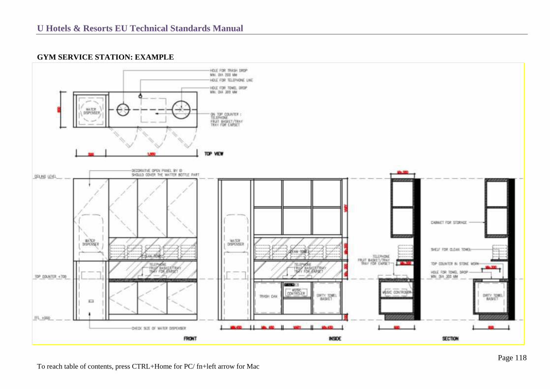
U Hotels & Resorts EU Technical Standards Manual
Page 118 To reach table of contents, press CTRL+Home for PC/ fn+left arrow for Mac
GYM SERVICE STATION: EXAMPLE
U Hotels & Resorts EU Technical Standards Manual
Page 119 To reach table of contents, press CTRL+Home for PC/ fn+left arrow for Mac
SPA & WELLNESS
The following information is a general overview only. The brief for this area should be drawn up with a specialized consultant.
SPA
These standards provide general guidelines and features of spas when operated jointly with U Hotels & Resorts. It does not attempt to define all the
possibilities and features of such spas in general.
For any given location and depending on the site, size, climate, supply and demand and technical considerations, a specific brief for an adapted spa will be
drafted together with a specialized consultant.
Thus the first step in the spa definition must be to designate this consultant. Along these guidelines, a site visit shall then be organized as a priority in order
to develop the Brief on an adapted technical basis.
The spa should include:
Access from the hotel, as well as for outside guests.
A reception – administration area with
o reception desk
o office displaying the treatment schedule
o retail space
o waiting area
Corridors connecting the different treatment areas.
Manager’s office.
Preparation area for herbs and spices to be used and combined with the employees’ area & toilet.
Treatment rooms – number of rooms will depend on the size of hotel.
Wet facilities area such as steam room, sauna, jet pool, or Vichy shower.
Relaxation area and yoga or meditation room.
All treatment rooms are open to daylight with outside private views wherever possible.
A quiet relaxation area with music, both open to daylight and natural surroundings.
Lounges with:

U Hotels & Resorts EU Technical Standards Manual
Page 120 To reach table of contents, press CTRL+Home for PC/ fn+left arrow for Mac
o Relaxation areas facing the view (if applicable).
o Reading corner / library.
Health food bar / drink station
Plant rooms and service rooms including :
o service entrance
o personnel lounge
o technical room for all spa facilities
Personnel locker rooms with vanity counter, showers and toilets.
Linen storeroom and supervised area for guests’ personal belongings.
As for the Spa, a shop and connection to a beauty salon is desirable.

U Hotels & Resorts EU Technical Standards Manual
Page 121 To reach table of contents, press CTRL+Home for PC/ fn+left arrow for Mac
GENERAL TECHNICAL INFORMATION
In each treatment room, the following should be provided :
o Full-height millwork with a sink, a linen drop basket, and cabinet for product/linen storage.
o Large floor drains in the showers (mud baths).
o Seating for foot ritual.
o A shower (if possible)
The main technical space should be easily accessible for any problems with the plumbing, drainage, floor drains, etc.
Floors should be completely waterproof with ceramic up stands and baseboards.
Treatment bed should be accessible from all sides with 0.90 meter of circulation space.
Power cables for mobile units with rollers should be high off the ground (no wires on the floor), or, provide floor outlet.
All lighting should be dimmable.
Independent licensed music provided by a central music system with volume control for each section.
SPA DISCLAIMER: EXAMPLE
SPA DISCLAIMER
Our hotel’s spa treatments are strictly provided for general relaxation purposes only and are not intended in any way to be a
substitute for professional medical diagnosis or treatment by a certified health professional for any condition, medical or otherwise.
Hotel and its management and staff hold no responsibility whatsoever on all liabilities, claims, expenses, damages and losses, including
legal fees, arising out of or in connection with the spa treatments, services and/or facilities.

U Hotels & Resorts EU Technical Standards Manual
Page 122 To reach table of contents, press CTRL+Home for PC/ fn+left arrow for Mac
SPA LAYOUT: EXAMPLE
SINGLE TREATMENT ROOM

U Hotels & Resorts EU Technical Standards Manual
Page 123 To reach table of contents, press CTRL+Home for PC/ fn+left arrow for Mac
SPA LAYOUT: EXAMPLE
DOUBLE TREATMENT ROOM

U Hotels & Resorts EU Technical Standards Manual
Page 124 To reach table of contents, press CTRL+Home for PC/ fn+left arrow for Mac
LOCKER EXAMPLE

U Hotels & Resorts EU Technical Standards Manual
Page 125 To reach table of contents, press CTRL+Home for PC/ fn+left arrow for Mac
TENNIS FACILITIES
Tennis courts must be covered with an officially approved surface:
o i.e. Astroturf, clay, cement
o have a 1% gradient from the axis centreline to prevent too much rainwater accumulating
o peripheral drainage surrounding the court must be provided
The court’s main axis should be north-south for open-air courts.
Avoid shadow casting on the courts (trees, buildings).
Avoid planting trees with extensive root systems near the tennis courts.
Showers, lavatories and locker should be designed in common with the other sports and fitness centre facilities.
The equipment must be designed in line with regulations approved by the International Tennis Federation.
Provide a separation fence between 2 adjacent courts.
Open air courts:
o Provide night lighting using fixed floodlights on lateral supports at least 9 m high.
o Lighting should be at least 300 lux through the volume in which the ball moves, i.e., up to around 4m from the ground, with a uniformity
factor of >7.
o Court lighting should be controlled by a programmable timer.

U Hotels & Resorts EU Technical Standards Manual
Page 126 To reach table of contents, press CTRL+Home for PC/ fn+left arrow for Mac
LAYOUT OF OPEN AIR COURTS
Covered courts:
The lighting required in the playing area is 500 lux. It can be provided by LED lamps etc. parallel to the court’s lengthwise axis.

U Hotels & Resorts EU Technical Standards Manual
Page 127 To reach table of contents, press CTRL+Home for PC/ fn+left arrow for Mac
LAYOUT OF COVERED COURTS

U Hotels & Resorts EU Technical Standards Manual
Page 128 To reach table of contents, press CTRL+Home for PC/ fn+left arrow for Mac
RESTAURANTS AND BARS
U Hotels & Resorts Restaurant Concepts
Regulatory Standards
Food and Beverage Principles
All Day Dining
Speciality / Theme Restaurants
Swimming Pool - Beach Restaurant/Bar
Bar Principles
Lobby Bar
Wine / Club / Exotic Bar
Cigar Lounge

U Hotels & Resorts EU Technical Standards Manual
Page 129 To reach table of contents, press CTRL+Home for PC/ fn+left arrow for Mac
U HOTELS & RESORTS CONCEPT
The U Hotels & Resorts food and beverage concept is based on:
Its ability to adapt this know-how and precisely adjust its offer to exceed the expectations of potential clientele, particularly local clientele.
The concept, for each restaurant, is based on a “stand alone” philosophy. In other words, each restaurant should develop its own identity separate
from that of the hotel, giving as much as possible the feeling that it is an independent operation.
However from a technical standpoint this concept, along with its objectives, must integrate a certain number of rules in terms of location, access,
layout, organisation, equipment and decor.
The food & beverage brief and customer capacity vary considerably, since each project depends on the market potential and type of hotel
(“business” or “resort”). However, there are always a certain number of basic concepts to consider, for example:
o Specialty restaurant
o All day dining
o Themed restaurants
o Swimming pool-beach restaurant/bar
o Bar
o Wine bar
The design, layout and equipment of these public F & B premises must respect a certain number of technical standards:
o Conform to local regulations (or agreed referenced international regulations by default). When both are available, the most stringent
provisions shall be applied.
o Meet the qualitative objectives of U Hotels & Resorts defined in the image standards.
o The precise food & beverage brief is defined for each project in a dedicated document.

U Hotels & Resorts EU Technical Standards Manual
Page 130 To reach table of contents, press CTRL+Home for PC/ fn+left arrow for Mac
REGULATORY STANDARDS
Health and Safety
The premises used as restaurants, bars, etc., must be suitably equipped to avoid any risk of contamination to the food products that are served or eaten:
Certain premises and equipment should not be installed nearby (waste collection, polluted effluents, etc.).
Public areas should be pressurized higher than the adjacent premises to avoid any transmission of odours, notably from the kitchens.
Walls, ceilings and floors as well as fittings should be designed to enable constant cleaning.
Adjacent public lavatories should never be directly accessible from the restaurant or bar areas. Hand-towel distributors must be installed close to the
sinks.
Health and safety regulations for F & B facilities must be respected and followed as per the 40 point check list provided by U Hotels & Resorts
Access for the Disabled
Generally, all F & B sales outlets must conform to disabled access standards. In the absence of local regulations, at least 1 restaurant and 1 bar should meet
these requirements.
Smoking Areas
It is quite common to have enclosed public areas, restaurants and bars as non-smoking areas.
Wherever possible, all restaurants and bars must have an area for smokers which should be located on the outdoor terrace. The same counts for the public
areas, which should allocate smoking areas with ashtrays and be well-marked.

U Hotels & Resorts EU Technical Standards Manual
Page 131 To reach table of contents, press CTRL+Home for PC/ fn+left arrow for Mac
FOOD AND BEVERAGE PRINCIPLES
Each food or beverage outlet within the hotel will receive a dedicated Food & Beverage brief including:
Theme or purpose of the outlet.
Specific interior guidelines with proposed materials, finishes, art effects etc.
Operational details with the amount of service stations, POS terminals, opening time, meal periods, manpower etc.
Proposed entertainment systems such as music, TV’s, live bands etc.
Indicative food and beverage menu.
Proposed uniforms.
Layout
Restaurants and bars should be grouped on the same level as the hotel’s main centres of activity.
They should have physical and visual contact with the outside and should never be located underground and, if possible, not on an upper floor.
The swimming pool restaurant/bar or some bars may sometimes be installed in a specific area.
As often as possible, food outlets should be grouped around or very close to the main kitchen for direct service. In other cases, the satellite kitchen
assigned to them should be at the same level and immediately adjacent to the areas served.
Whenever possible, their assigned areas should be free of:
o Columns.
o Architectural elements which create constraints should be removed or isolated such as:
o corridor effect
o dead corners that are difficult to integrate
o differences in levels
o noisy areas or sources of pollution
U Hotels & Resorts EU Technical Standards Manual
Page 132 To reach table of contents, press CTRL+Home for PC/ fn+left arrow for Mac
Signage-Access
In addition to inside access, the restaurants and bars are located to provide direct access from the outside (separate from the hotel entrance).
Inside visibility and access for the hotel’s guests should be clear and simple with the appropriate directional signage, in conformity with U Hotels &
Resorts standards.
The outside access is attractive and well-lit and sets of double doors.
Windows should always be clear and protection from the sun provided when necessary.
Each sales outlet is indicated by a specific sign, both outside and inside, in harmony with the general signage.
Lighting-Electricity
Several circuits should be used in the electrical installation including a backup circuit.
The lighting must be adjustable using several pre-programmed dimmers, located at the reception desk of each outlet.
Provide special lighting with low voltage spotlights for buffets and displays, special lighting for a band in the entertainment area and lighting for the
menu boards and signs.
Provide enough electrical connections for at least:
o Reception / hostess desk : power outlets, 1 lecturer light
o Computerised cashier stations installed in the room: computer LAN and electrical outlets (with backup) and credit card terminal outlets.
o Maintenance: 1 baseboard power outlet along the walls every 7 m and at the base of each column.
o Service stations: outlets for hot plates and P.O.S. equipment (LAN and electrical).
o Live music: suitable power outlets built in the baseboards or floor.
o In the buffet area, built-in outlets for mobile equipment.
Buffet
When a buffet style breakfast or meal is served, it should preferably be composed of fixed or mobile, refrigerated, heated or neutral elements, plate-
warming and induction chafing dish units and live station if possible.
Electrical outlets should be positioned to allow changes in the arrangement of buffets.
In general, the buffets must be visible from the restaurant entrance, easily accessible by customers even at peak times (double the service lines).

U Hotels & Resorts EU Technical Standards Manual
Page 133 To reach table of contents, press CTRL+Home for PC/ fn+left arrow for Mac
Computerised P.O.S. System and Cash Registers
According to U Hotels & Resorts specifications, the order taking and bill-printing terminals must be set up next/within to the service stations
(P.O.S. system) and linked to the local area network.
Each cashier stand (one to two per outlet, in addition to the ordinary P.O.S. terminals) should have a credit card swipe machine (EDC), linked to the
telephone network.
Sound System
Provide a quality sound system (with adjustable volume for every area) which can receive either one of the hotel’s central channels, or
programming specific to the different sales outlets. It should be installed in the back office server rack. This is likely to be in the form of a PC with
soundcard and loaded with licensed music connected to an amplifier and speakers.
Telephone
Each sales outlet should be equipped with an extension/telephone line that can be switched over (for restaurants) to the F & B Management office,
and /or the switchboard to take reservations when the restaurant is closed.
The phone must be on the reception or hostess stand and the ringer volume adjustable.
A cordless phone should also be provided for guest use.

U Hotels & Resorts EU Technical Standards Manual
Page 134 To reach table of contents, press CTRL+Home for PC/ fn+left arrow for Mac
SERVICE STATION LAYOUT

U Hotels & Resorts EU Technical Standards Manual
Page 135 To reach table of contents, press CTRL+Home for PC/ fn+left arrow for Mac
HOSTESS COUNTER

U Hotels & Resorts EU Technical Standards Manual
Page 136 To reach table of contents, press CTRL+Home for PC/ fn+left arrow for Mac
Ventilation-Air Conditioning
Each room should have its own air conditioning thermostat, controlled according to its level of occupancy.
Whenever possible, particularly for the bars, natural ventilation should be provided.
Avoid creating a cold barrier along the windows.
When regulating the air conditioning, compartmentalized dining rooms should be kept in mind.
Kitchen
Provide an entry space with two sets of double swinging doors (no centre post) between each sales outlet and its service area (kitchen, pantries).
This conceals the area and provides soundproofing.
The doors will be provided with bull’s eye windows and kick protection plates on both sides.
The space between the two sets of doors in each entry should be large enough (1.5 meters) to hold a removable double step doormat.
The services bars, open kitchens and special pantries are described in chapter C15-Kitchens.
Service Stations and Cashier
The service stations (see drawings) should be spread around the room, one for every 20 to 25 place settings.
In addition to their service and clearing functions they must include the computerised point of sales (P.O.S.) and bill-printer terminals.
They should have spare power outlets as well for the P.O.S. and printer terminal power and LAN (RJ45) outlets.
In the restaurants one station, located near the entrance or in the bar counter, is dedicated to the cashiers’ stand. In gourmet and specialty
restaurants, this is generally located in the kitchen pantry area. In the bars it is incorporated into the bar counters.
Furniture and Equipment
Apart from the functional elements described below, the decor of all outlets should always include objects and artwork directly related to its
personality and properly chosen and highlighted by the interior designer.
The furniture should be selected by the interior designer with U Hotels and Resorts Management approval according to the concept of each outlet,
with the following standards in mind:
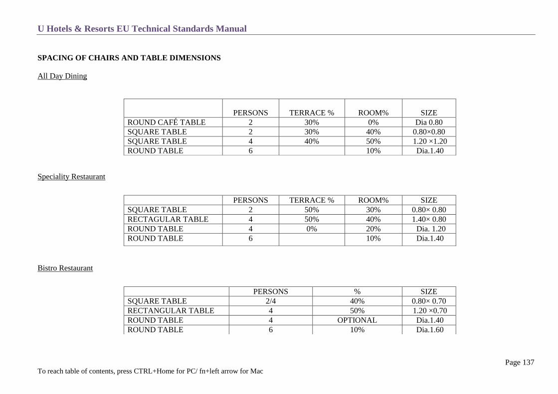
U Hotels & Resorts EU Technical Standards Manual
Page 137 To reach table of contents, press CTRL+Home for PC/ fn+left arrow for Mac
SPACING OF CHAIRS AND TABLE DIMENSIONS
All Day Dining
Speciality Restaurant
Bistro Restaurant
PERSONS
TERRACE %
ROOM%
SIZE
ROUND CAFÉ TABLE 2 30% 0% Dia 0.80
SQUARE TABLE 2 30% 40% 0.80×0.80
SQUARE TABLE 4 40% 50% 1.20 ×1.20
ROUND TABLE 6 10% Dia.1.40
PERSONS TERRACE % ROOM% SIZE
SQUARE TABLE 2 50% 30% 0.80× 0.80
RECTAGULAR TABLE 4 50% 40% 1.40× 0.80
ROUND TABLE 4 0% 20% Dia. 1.20
ROUND TABLE 6 10% Dia.1.40
PERSONS % SIZE
SQUARE TABLE 2/4 40% 0.80× 0.70
RECTANGULAR TABLE 4 50% 1.20 ×0.70
ROUND TABLE 4 OPTIONAL Dia.1.40
ROUND TABLE 6 10% Dia.1.60

U Hotels & Resorts EU Technical Standards Manual
Page 138 To reach table of contents, press CTRL+Home for PC/ fn+left arrow for Mac
Bars
Furniture height to be determined (meal service)
Table with adjustable bases should not be used as they are not stable.
The restaurant table height should be 75 cm and the chair seats 45 cm high.
The bar table depth should be 45 cm (60 cm if snacks and meals are served).
Chairs and armchairs must be equipped with silent plastic disks on hard floors and gliders on carpets.
If the seats and backs are covered with fabric, they should be treated against stains and be removable and washable.
When the furniture includes benches their height and seating depth must be carefully gauged to the height of the table for maximum comfort (max.
height difference 30 cm). A prototype should be tested and submitted for approval.
PERSONS SIZE
SEATS AT COUNTER AS PER HOTEL BRIEF
ROUND CAFÉ TABLE 2/3 Dia.0.80
ROUND CAFÉ TABLE 4/5 Dia. 1.10
RECTANGULAR TABLE 4/6 0.70 × 1.10
TABLE FINISH TOP BASE
ALL DAY DINING &
SPECIALITY
wood or marble with rim or hard
aesthetic and washable material
Cast iron or varnished
metal
BISTRO RESTAURANT hard/washable material
chosen by interior designer
wood or varnished cast
aluminium
BARS covering chosen by interior
designer
interior designer’s easy
maintenance choice

U Hotels & Resorts EU Technical Standards Manual
Page 139 To reach table of contents, press CTRL+Home for PC/ fn+left arrow for Mac
Deli / Gourmet Restaurant
Service stations and tables arranged against the walls must be equipped with rear stops.
Table decor
This category includes the following items:
tablecloth, napkins
flatware (silver plate or polished stainless steel)
dinnerware
glassware
all other items used to set tables (vases, candleholders, etc.)
Their selection is based on qualitative criteria:
suitable for professional use (resistant, durable)
matches or expresses the restaurant decor and concept
financial budget of each project
Their technical specifications are to be found in the OPE list.
U Hotels & Resorts EU Technical Standards Manual
Page 140 To reach table of contents, press CTRL+Home for PC/ fn+left arrow for Mac
ALL DAY DINING
Concept
The All Day Dining outlet is the hotel’s main restaurant. It is located close to the lobby and served by the main kitchen.
A lively and friendly restaurant with its formula and decor adapted to meet client expectations: either typical and traditional or adapted to the local style.
Depending on the situation, it can be positioned as an informal restaurant.
It is most often a reasonably priced restaurant open for breakfast, lunch and dinner (possibly even afternoon tea and late dinner).
Serves a continental buffet and a la carte menu, possibly even a brunch once a week.
The decor is typical and cordial but its quality and personality must be outstanding. The atmosphere is informal and friendly.
The cooking will be both western and local fare.
Operation
In most hotels, it is the F & B sales outlet that serves the largest number of individual customers for breakfast, lunch and dinner. Its capacity should be
adapted to the market and the total number of restaurants in the hotel.
The classic design is composed of 3 main areas: bar, dining room, and outdoor terrace.
The bar has 2 functions:
Attract and draw the clientele in from the outside. It should be located close to the outside entrance.
Waiting bar serving snacks and beverages and a service bar serving the restaurant’s beverages.
Whenever possible it should be located next to the kitchen serving the all-day dining restaurant.
Dining Room
Mostly used for serving meals but may also serve afternoon tea, snacks or late suppers depending on the time of day.

U Hotels & Resorts EU Technical Standards Manual
Page 141 To reach table of contents, press CTRL+Home for PC/ fn+left arrow for Mac
Terrace
Open or covered depending on weather conditions; air conditioned or heated if necessary.
It should have a wide view to the outside through sliding glass doors.
Mostly used for serving snacks and beverages during the day.
Meals can also be served during peak hours (extension of the dining room).
The all-day dining can accessed from the outside through a specific entrance, but it also has direct access from the lobby for hotel guests.
Minimum area requirement: 2 m²/chair
Decor and Equipment
The seating and table arrangement should be separated into different areas, shapes and heights to avoid monotony.
The ceiling design must incorporate into the room’s general decor and add to the harmony. Technical elements (lighting, air conditioning, sound
system) must also blend with the decor.
The quality of day lighting is particularly important. The windows must be clear.
Lighting should be indirect and carefully designed. All lighting should be installed over 1.80 m from the floor, so as not to be obtrusive. No
individual lighting is necessary. The floor should never be lit, unless a high quality and easily maintained material is used.
The benches and chairs must be set up to serve tables for 2, 4, 6, and 8 diners.
The décor and art effects’ major aspects should be drawn from what makes this market place popular
The furniture should be simple and durable but comfortable and in character with the type of restaurant.
The bar counter with any kind of durable top should be equipped with a foot rail. The bar counter’s basic equipment is identical to that described in
chapter C 14 Kitchens; additional equipment such as a draft beer installation may be added depending on the Food & Beverage Brief.
Flowers and plants (notably on the terrace) should be carefully arranged as they are part of the decor concept.
U Hotels & Resorts EU Technical Standards Manual
Page 142 To reach table of contents, press CTRL+Home for PC/ fn+left arrow for Mac
SPECIALITY RESTAURANT
Concept
The hotel’s specialty restaurant usually (but not exclusively) serves refined cuisine with a special theme to stand out in the local restaurant scene.
It plays a fundamental role in how the hotel, its general activity and its food & beverage service is perceived locally (particularly banqueting business), and
is a reflection of the brand image of all U Hotels & Resorts hotels.
Its main characteristics (other than the food served) are a refined decor with personalised, superlative service.
It should serve lunch and dinner.
The classic or modern decor should be elegant, refined and very comfortable.
Operation
Provide a separate entrance from the roadside if possible to give a free standing feel to the outlet.
Provide a small reception and beverage bar as a waiting area with seating possibilities.
The seating amount for the restaurant should be determined according to the initial market study and as defined in the Food & Beverage Brief.
Provide 2 small private rooms adjacent to the dining area (with a private entrance if possible) to accommodate between 8 and 12 people.
Space the table’s well-enough apart to reinforce the feeling of comfort and luxury and to provide a calm and private setting at each table and
facilitate service around the chairs.
Recommended density: 3 m²/ chair.
Décor and Equipment
The restaurant’s decor must reflect sophistication and peace. The atmosphere and style should reinforce the idea of space, comfort, luxury and
refinement.
Natural lighting is necessary for the lunch service.
The artificial lighting must be adjustable and be flattering to both diners and food.
In order to divide the room into several areas, provide folding screens or openwork partitions which look part of the restaurant.
The floor must be covered with a stretched, high quality woven carpet except in high traffic areas and tropical countries where it is preferable to use
a high quality, easily maintained hard floor covering with occasional rugs.
The chairs must have wooden arms low enough to slide under the table.
Provide small service tables (one for every 10 place settings).

U Hotels & Resorts EU Technical Standards Manual
Page 143 To reach table of contents, press CTRL+Home for PC/ fn+left arrow for Mac
A spot lit “show piece” (tapestry, pottery, sculpture etc) should mark the entrance to the restaurant.
Walls and ceilings should be made with sound absorbent materials for the acoustic comfort of guests.
Small stools should be available for ladies handbags etc.
THEMED RESTAURANTS
These restaurants are a basic element of the hotel’s food and beverage activity and their decor must create a completely different surrounding. Minimum
area requirement: 2m²/ chair.
LOCAL CUISINE RESTAURANT
This restaurant’s essential quality is its authenticity and credibility which must initially show through the decor and interior design.
Creating this type of restaurant requires an in-depth study of the habits and customs of the country in which the hotel is established.
These factors must be taken into account at the start of the project.
The restaurant’s kitchen, most often independent, should meet the special requirements of the type of cooking served and the work habits.
An outside location is frequently used.
THEMED CUISINE RESTAURANT
The aim of this restaurant is to use a typical concept based either on the culinary tradition of a country or on a range of foods (grilled, seafood, etc.) or even
a restaurant style (steakhouse, tavern, tapas bar, etc.) and develop the appropriate surroundings and entertainment. The theme and decor must be developed
to a maximum degree, without turning into a caricature, in order to offer a completely unique eating and entertainment experience. Many elements can
create this experience, such as cooking or preparing food “a la minute” in front of the guest.

U Hotels & Resorts EU Technical Standards Manual
Page 144 To reach table of contents, press CTRL+Home for PC/ fn+left arrow for Mac
FOOD MARKET
The “Food Market” comprises of several small restaurants: traditional, local or themed (with the characteristics defined above) and gathered in one area
(mall, promenade, and square).
The wide choice of restaurants, decors, foods and prices is the main attraction.
The Food Market is above all a centre of activity and aimed at the local clientele as well as hotel guests.
It should be designed to create unity.
Although every restaurant should have its own typical decor, the central area (mall, promenade, square, etc.) must have a coherent and attractive style
different from the hotel’s usual decor. This style should highlight the windows, facades and characteristic signs of each sales outlet. On a practical level,
these restaurants can be totally independent from the central facilities, which are usually far removed. Their kitchen, pantry and storage areas are separate,
although some of them may be shared. Because several outlets may be grouped this way, the capacity of each should be limited (about 40 seats).
SWIMMING POOL – BEACH RESTAURANT/BAR
This outlet has a simple menu and several functions. It serves:
lunch and dinner,
snack, sandwiches and beverages all day
as a centre of activity for buffets and theme nights (particularly in resort hotels)
This restaurant must be designed as an informal area for relaxation but functionally equipped for complete operational autonomy. In certain cases, this
outlet only acts as a bar (see following paragraph).
Its layout and functions vary greatly between “business” and “resort” hotels.
Business Hotel
The restaurant or “pool-snack” serves lunch, snacks and beverages during the day and sometimes dinner.
In certain hotels (limited potential market), it may act only as a bar, in which case it should be designed for this purpose only.

U Hotels & Resorts EU Technical Standards Manual
Page 145 To reach table of contents, press CTRL+Home for PC/ fn+left arrow for Mac
Resort Hotel
Here the beach restaurant/bar plays an essential part in the hotel’s entertainment in general and acts as a liaison between the beach and swimming
pool.
It must therefore be designed as an independent and autonomous restaurant and serve:
o Meals using prepared or pre-cooked food
o Beverages and refreshments
o The swimming pool and beach
o It is also an ideal sales outlet for buffets and theme nights.
In its most complete version, the restaurant/bar should include the following areas:
o bar
o service counter for finishing and /or serving meals
o open cooking-preparation area : barbecue
o pantry area with the following functions :
service pantry
Cooking - preparation area (with extraction fan, grease filters, etc.)
dish, pots and pans washing area
refrigerated storerooms
temporary garbage collection area
Ventilation, air conditioning and soundproofing of pantry areas must be designed to avoid any nuisance and optimise working conditions.
The layout should be based on the dominant winds.
Provide a service access for carts.

U Hotels & Resorts EU Technical Standards Manual
Page 146 To reach table of contents, press CTRL+Home for PC/ fn+left arrow for Mac
Decor and Equipment
The lighting and sound system must be designed to accommodate entertainment or dancing and should be integrated with the landscaping of the
pool. A special place should be reserved for this purpose (podium).
Special care must be given to the sound system, which must be of high quality but avoid any excess noise for the hotel guests. (Distance, screens,
orientation etc.).
The decor should have a local theme. Local architectural touches and the use of local crafts should underline the originality of the swimming pool
restaurant/bar.
The furniture should be simple, comfortable, functional and different in the meal area, which may be a terrace (covered or open depending on
weather conditions) or the “beach/pool” relaxation area. It should be weather and rot-resistant, easily cleaned, in light and bright colours and of
“natural” materials: quality synthetic resin, rattan, teak, treated ecru canvas, etc.
There should be enough tables, chairs, café tables and parasols to meet the needs of the Food & Beverage Brief.
Since the tables are usually not covered, the table tops must be made of an attractive and easily cleaned material.
Equipment marked with advertising (regardless of the sponsor’s quality) is never to be used.
Provide a shaded area: verandas, canopies (made of traditional materials), parasols, etc.
Provide an additional storeroom (aside from the swimming pool equipment storeroom) to store the various items required for special events.

U Hotels & Resorts EU Technical Standards Manual
Page 147 To reach table of contents, press CTRL+Home for PC/ fn+left arrow for Mac
BAR PRINCIPLES
The term “bar” means any sales outlet whose main activity is the sale of beverages, with or without alcohol, possibly accompanied by limited food service
(cocktail snacks, etc.). Bars may be quite varied and are differentiated mainly by their setting and decor.
Bars should be designed to provide easy access for hotel guests as well as local clientele and close to a busy passageway or area with considerable
activity.
(There should be clearly indicated signs and directional signage).
Regardless of the type of bar (club, lounge, waiting area, theme (exotic) or discotheque), the technical facilities must include:
o a bar counter with :
On the guest side
A hard (stone, wood or metal) totally washable material for the top (height = 110 cm ; width = 40 cm minimum), with a slight
overhang
A foot rest (height = 20 cm)
On the service side: (H = 85-90 cm)
Front refrigerated unit, double sink, cocktail unit, POS and credit-card terminal plus spare outlets and telephone.
Back refrigerated unit equipped with doors and shelves, bottles displayed in the top part (unit must be locked when bar is closed:
sliding panels or rolling shutters).
o a pantry with :
Beer pump and storage as per the Hotel Brief
Storage for the day
A glass washing area with glass washing machine
Icemaker
Hot and cold water sink with dish rack
Possibly a coffee machine

U Hotels & Resorts EU Technical Standards Manual
Page 148 To reach table of contents, press CTRL+Home for PC/ fn+left arrow for Mac
The pantry should be located behind the counter area (direct access) and be large enough to provide the bar with enough autonomy during opening
hours and avoid any traffic linked to clearing or supplying through the hotel’s public areas.
The bars should be equipped with:
o A service telephone and cordless phone.
o Independent sound system.
o Light dimmers.
o Video-projector integrated in the ceiling with built-in electric screen, according to the Hotel Brief.
o Band area if applicable with all the necessary outlets, according to the Hotel Brief.
o TV outlets.
Provide service stations with P.O.S. and Printer terminals.
For the signage, refer to the Corporate Identity Manual and chapter C-22 Signage.

U Hotels & Resorts EU Technical Standards Manual
Page 149 To reach table of contents, press CTRL+Home for PC/ fn+left arrow for Mac
SAMPLE BAR DRAWING

U Hotels & Resorts EU Technical Standards Manual
Page 150 To reach table of contents, press CTRL+Home for PC/ fn+left arrow for Mac
LOBBY BAR
Concept
The bar should be open and integrated near the hotel lobby to create a pleasant extension of the hotel. It is a natural waiting and meeting area, very
visible and easy to reach and usually located in a public traffic area.
Operation
The bar serves all types of beverages, as well as coffee and tea, day and night.
It may act as the waiting area for the brassiere.
It includes 2 areas:
o A discrete and more intimate area.
o A table area visible from the lobby.
Decor and Equipment
It is preferable to use hard floor coverings.
The furniture should differ from area to area.
The terraces should include small tables, chairs and a few stools around the bar, while the more intimate area should have light armchairs and
settees (avoid ottomans).

U Hotels & Resorts EU Technical Standards Manual
Page 151 To reach table of contents, press CTRL+Home for PC/ fn+left arrow for Mac
WINE / CLUB / EXOTIC BAR
Concept
This type of bar is enclosed, and has a “private club” atmosphere, refined setting and comfortable facilities that make it an ideal meeting point for
local clientele and hotel guests. It plays an important role in integrating the hotel into the city’s lifestyle and can be themed around a wine bar.
Operation
This is an enclosed bar highlighting the sales of wines located near the restaurants.
Decor and Equipment
Its atmosphere is intimate and its decor refined and comfortable with armchairs and low armless chairs.
The furniture should be arranged to accommodate groups of 2 to 5 people.
Provide an area for entertainment (piano or even a band) with power outlets and sound system.
The floor should be covered with high-quality, woollen carpets stretched on underlay.
EXOTIC BAR
This is a theme bar differentiated by its decor and playfully entertaining atmosphere.
It is an essential entertainment sales outlet for certain hotels.
It operates like the club bar and can be substituted for the latter.

U Hotels & Resorts EU Technical Standards Manual
Page 152 To reach table of contents, press CTRL+Home for PC/ fn+left arrow for Mac
CIGAR LOUNGE
Concept
The cigar lounge, or cigar bar, allows after meal smoking and coffee and liquor drinking in a very classical and comfortable atmosphere.
Operation
Located close to and working in co-ordination with one of the main restaurants.
There is a small counter, used mainly for service.
Decor and Equipment
Different themes are possible, the British-club, with leather-covered “Chippendale” furniture being the most obvious.
It is a quiet place with a thick carpet, antiques and a fireplace where applicable.
The cigar and liquor storage is enhanced, to emphasize the preservation and quality selection of the products.
Special care is taken to provide proper ventilation and avoid any spreading of smoke to adjacent areas.
U Hotels & Resorts EU Technical Standards Manual
Page 153 To reach table of contents, press CTRL+Home for PC/ fn+left arrow for Mac
CONFERENCE AND FUNCTIONS
General Principles
Access Lobby / Foyer
Ballroom (multi-purpose room)
Meeting Rooms
Decor
Lighting and Equipment
Furniture
Back – Of – The – House Areas
Audio – Visual Management Alternatives
U Hotels & Resorts EU Technical Standards Manual
Page 154 To reach table of contents, press CTRL+Home for PC/ fn+left arrow for Mac
GENERAL PRINCIPLES
Operating Principle
The design and decor of the facilities and function rooms should reflect a multi-functional use.
They usually give onto open spaces such as foyers and corridors and include cloakrooms and public toilets.
Whenever possible they should be located on the ground floors with separate entrances.
Service corridors independent from those of the public serve the different rooms and lobbies.
These rooms should benefit from natural lighting during the day but must be possible to black-out the openings during projections.
Wherever possible they should have outside terraces and gardens for smoking areas and or events.
Rooms may be grouped or separated by soundproof folding partitions, integrated in the architecture.
o These soundproof, non-combustible folding partitions can be handled by one person, they do not require a ground track (noise reduction 48
dB (A) or STC, including ceiling insulation, to achieve an in-situ better than Dn or NR45), and are used to vary utilization of the rooms,
particularly the dimensions of the ballrooms.
Sufficiently large storage spaces, well-distributed and accessible by all rooms, should be provided to store the mobile furniture:
o Movable raised platforms, dance floors, decorations, chairs, tables, etc.
o It must be possible to store all banquet equipment outside of the function rooms.
The floors of each conference room, including the service corridors, must resist an imposed duty load of 500 kg/m² minimum.
A service entrance should be provided for truck delivery of banquet and exhibition equipment and include loading dock, goods lift, sash openings
and doors. Minimum width: 250 cm, height: 240 cm.

U Hotels & Resorts EU Technical Standards Manual
Page 155 To reach table of contents, press CTRL+Home for PC/ fn+left arrow for Mac
ACCESS LOBBY / FOYER
It communicates with the hotel lobby and if possible has another direct access to the outside.
All the lobbies should absorb the increase in traffic caused by the activities of the rooms, without there being any repercussions on the hotel’s
regular operation.
If there is a difference in levels between the entrance and the conference rooms, specific elevators and/or escalators or stairs must be provided.
In addition, a staircase should constitute as integral architectural element and limit the use of mechanical means of access.
The area has to be multi-functional to be able to accommodate coffee breaks / buffets or exhibitions or displays.
U Hotels & Resorts EU Technical Standards Manual
Page 156 To reach table of contents, press CTRL+Home for PC/ fn+left arrow for Mac
BALLROOM (MULTI-PURPOSE ROOM)
Purpose
It must be suitable for a wide variety of uses:
Conferences and meetings
Weddings
Banquets and cocktail parties
Exhibitions, fashion shows
The ceiling height must be proportional to the room size. Normally a minimum height of 5.5 m is required.
Conferences
Provide professional audio visual systems currently in use:
o Wireless microphones
o HDMI access to projectors with audio
o Hidden screens
o Pre-set lighting system with different themes
The equipment must be dividable so that each part of the room can be used individually.
Banquets
A satellite kitchen makes it possible to serve a large number of meals prepared in the main kitchen (hot and cold transfer system.) Service doors to
kitchen and set-up areas are double, thus forming an air lock.

U Hotels & Resorts EU Technical Standards Manual
Page 157 To reach table of contents, press CTRL+Home for PC/ fn+left arrow for Mac
MEETING ROOMS
They are designed for meetings and small conferences.
Most of them should be supplied by the satellite kitchen of the ballroom via the service
corridors.
The rooms should be located to receive as much daylight as possible.
Provide professional audio visual system currently in use:
o Wireless microphones.
o HDMI access to oversized television screens or projectors with audio.
o Hidden screens.
o Pre-set lighting system with different themes.
U Hotels & Resorts EU Technical Standards Manual
Page 158 To reach table of contents, press CTRL+Home for PC/ fn+left arrow for Mac
DECOR
The décor has to be adaptable to accommodate all aspects from a working environment to festive settings.
The finishing materials should be extremely resistant.
o Door edges need to be protected
o Doors should have a bracing system to keep them open
o Walls, up to 0.9 -1.0 m should have a hard surface such as stone above alternate panels of mirroring and padded material to soften the room.
o Floors: Axminster carpet (80/20 - wool/nylon) or hard surface such as stone with carpet rugs
It should be possible to modify all the decor elements (including lighting) to expand utilization possibilities. The decor should be designed so that
each room has a personality that corresponds to its name, within a uniform setting.
The meeting rooms should be identified by individual 22” TV screens, recessed into the wall adjacent to each meeting room access.
U Hotels & Resorts EU Technical Standards Manual
Page 159 To reach table of contents, press CTRL+Home for PC/ fn+left arrow for Mac
LIGHTING AND EQUIPMENT
Requires a dimmer system with minimum of 6 to 8 theme settings from a working environment to a festive setting for:
o Conferences
o Presentations
o Entertainment
o Weddings
o Fashion Shows
Separate stage lighting is required in larger function rooms.
Any chandeliers should not obstruct video or any other projections.
Individual built-in and hide-away projectors and screens for each room.
Specific temporary lighting should be provided for buffets (along one end of the room).
Emergency lighting blocks (emergency exit and ambient lighting) must be carefully integrated in the decor.
There is a clear distinction between room lighting, which is fixed and entertainment lighting, which is additional (and often subcontracted to outside
firms).
The banquet areas should also be able to accommodate the installation of equipment specific to the different types of events: video projector,
movable decor, light suspension bridge, portable A/V control board, stage curtains, screen, buffets, exhibits, etc.
With this in mind, the different rooms and foyers should be equipped with the following equipment also perfectly integrated in the room decor:
Room control boards (switches, pre-programmed control buttons);
Located in each room close to the entrance at 120 cm from the floor. A faceplate which controls the following functions:
o Light switch with pre-programmed light settings.
o Volume control.
o “Up and down” controls for ceiling recessed screens.
o “Open and close” controls for black-out curtains.

U Hotels & Resorts EU Technical Standards Manual
Page 160 To reach table of contents, press CTRL+Home for PC/ fn+left arrow for Mac
Conference Modules
Each room should contain a minimum of one face plate 30 cm above the floor containing:
o Telephone & LAN access (RJ 45 with CAT 6E cabling).
o TV outlet (Digital or Analogue, depending on the guest room system).
o Minimum 2 HDMI outlets connected to the control booth.
o Minimum 4 outlets of earthed power sockets of 220V with international face plates.
There should be enough of these modules to limit the amount of electric cables on the floor; a minimum of 1 per room and within the foyer or
approximately every 8 meters apart. One station should be close to the podium location of each room.
Power supply 16 A+E electrical outlets with 2 phase and 32 A+E protected high voltage outlets with 3 phase and 415V located within each room
close to the stage area.
Fixed hanging bars for spotlights and moving heads. The associated electrical outlet boxes should be concealed behind trap doors in the drop
ceiling.
Lighting bar conceal hanger for large ballroom

U Hotels & Resorts EU Technical Standards Manual
Page 161 To reach table of contents, press CTRL+Home for PC/ fn+left arrow for Mac
Plates with double hooks set in the drop ceiling space, with trap doors for access and used to hang a light suspension bridge for shows. Along each
plate electric connection boxes with outlets linked to the control booth.
LCD projector mounts, concealed behind trap doors in the drop ceiling. Next to each support in the drop ceiling space, LCD projector connection
boxes linked to the conference module (power outlet + remote control and video link: Barco system).
Built – in projection screens, controlled from the conference modules and the control booth.

U Hotels & Resorts EU Technical Standards Manual
Page 162 To reach table of contents, press CTRL+Home for PC/ fn+left arrow for Mac
Speakers in the ceiling (and on the wall in the main function room) linked to the control booth including subwoofer for the main function room.
Blackout curtains in front of windows, electrically controlled from the conference modules.
Mouldings for wall hangings, on the periphery of rooms and the foyer.
Lighting tracks with low voltage spotlights integrated in the ceiling on the periphery of rooms to light the boards
Decorative tracks recessed in the drop ceiling on the periphery of certain rooms to hang various items (stage curtains, mobile decor, etc.), identical
to the mobile wall tracks.
Maintenance electrical outlets all around the room at every 8 meters if possible combined with the conference module plate.
Portable telephone outlets at the entrance of each room and in each foyer for the hostesses.
Direct TV outlets in each room within the conference module system
Surveillance cameras and remote video cameras linked to monitors in the control booth and with the ability to project onto the screens within the
rooms.
The air conditioning in each room should take into account the heat generated by:
o Lighting
o Entertainment lighting
o Hot buffets and live stations
o Maximum occupation during cocktail parties, i.e. 0.75 m²/person
Each room must be independently controlled with thermostats in the room and not accessible to the public. The trap doors in the drop ceiling should
be made of metal, without hinges.
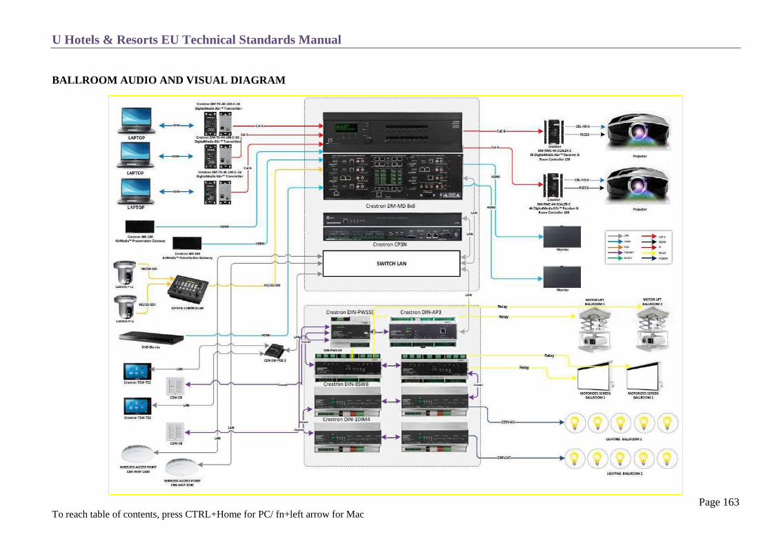
U Hotels & Resorts EU Technical Standards Manual
Page 163 To reach table of contents, press CTRL+Home for PC/ fn+left arrow for Mac
BALLROOM AUDIO AND VISUAL DIAGRAM
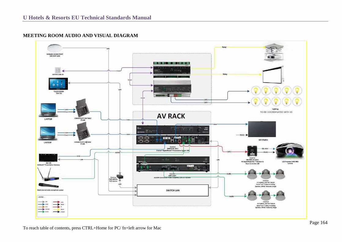
U Hotels & Resorts EU Technical Standards Manual
Page 164 To reach table of contents, press CTRL+Home for PC/ fn+left arrow for Mac
MEETING ROOM AUDIO AND VISUAL DIAGRAM

U Hotels & Resorts EU Technical Standards Manual
Page 165 To reach table of contents, press CTRL+Home for PC/ fn+left arrow for Mac
FURNITURE
The furniture must be flexible in order to adapt to various types of meetings. It should be solid and light. Chairs and armchairs should be stackable. See
Hotels OPE list.
Within the foyer reception only desks with chairs should be permanent units which are movable if required. Also if space is sufficient within the foyer area
seating corners should be created with coffee tables.

U Hotels & Resorts EU Technical Standards Manual
Page 166 To reach table of contents, press CTRL+Home for PC/ fn+left arrow for Mac
BACK OF THE HOUSE AREAS
Employee toilets for both men and women.
Sufficient amount of storage space near the rooms or along the service corridors, to store all the mobile banquet furniture. Provide 20% of the ball
room’s surface area.
Audio visual control booths with specific storage room (centralization of all conference audio-visual equipment, and in certain cases, that of entire
hotel).
Optional offices and optional storage for an AV manager, as per the Hotel Brief (equipment identical to that in administrative offices).

U Hotels & Resorts EU Technical Standards Manual
Page 167 To reach table of contents, press CTRL+Home for PC/ fn+left arrow for Mac
AUDIO – VISUAL MANAGEMENT ALTERNATIVES
Using Outside Services
In this case, rooms should be built with all the basic equipment in terms of wiring, connections and furniture with management assigned to an integrated
subcontractor.
This reduces the investment in terms of equipment and implies complete subcontracting of labour, equipment and maintenance.
Not Using Outside Services
This requires a substantial investment in terms of equipment and U Hotels & Resorts personnel to manage and maintain the installations.
The design must enable simple utilization. The equipment should be chosen from local distributors capable of providing the appropriate replacement
equipment and service.

U Hotels & Resorts EU Technical Standards Manual
Page 168 To reach table of contents, press CTRL+Home for PC/ fn+left arrow for Mac
ADMINISTRATION
General
Meeting Rooms
Offices Accessible to Guests
Other Offices
U Hotels & Resorts EU Technical Standards Manual
Page 169 To reach table of contents, press CTRL+Home for PC/ fn+left arrow for Mac
GENERAL
All offices should, if possible, have natural lighting.
The exact number of offices is defined in the Facility / Hotel Brief.
A separate workstation will be provided for the General Manager’s Secretary.
The accounting department, the computer room and the General Cashier are located in the same area.
Each working station will have 1 telephone and 2 LAN (R.J. 45) outlets and 2 double electrical sockets.
See FF& E listing for furniture and office equipment.
MEETING ROOMS
Located in the middle of office area and equipped with a white board and LCD projection equipment.

U Hotels & Resorts EU Technical Standards Manual
Page 170 To reach table of contents, press CTRL+Home for PC/ fn+left arrow for Mac
OFFICES ACCESSIBLE TO GUESTS
These offices should be able to receive guests or suppliers through the welcome area and its waiting area without passing through the service corridors.
This concerns the following positions:
General Manager
Food & Beverage Manager (also in contact with the employees)
Banqueting Manager
Financial Controller (with accounting)
Director of Sales & Marketing and team (if on site)
Director of Events and team
Others accessible to guests
Accounting
There will be, for example, in a 100-room hotel about 6 posts. The exact number is defined in the Hotel Brief.
2 separate offices at least should be provided:
1 for the Financial Controller
1 for the General Cashier (with the service safes and a counter opening on a service corridor).

U Hotels & Resorts EU Technical Standards Manual
Page 171 To reach table of contents, press CTRL+Home for PC/ fn+left arrow for Mac
OTHER OFFICES
Photocopying and Telecommunications
It includes a photocopy machine, fax machine, computer with internet access, reservations terminal and cupboard.
Computer Room
A specialised room which is explained under T-13 IT & Low Voltage.
Storage and Coffee Room
It includes key-locked cupboards for supplies and all necessary mechanical and electrical connections (electrical, cold and hot water, sink
drainage).
Archives and Files
It is a key-locked small room for administrative archives.
Sales Supplies Room
It stores folders, brochures, leaflets etc. next to or in the sales office.
Toilets
Unisex toilets.

U Hotels & Resorts EU Technical Standards Manual
Page 172 To reach table of contents, press CTRL+Home for PC/ fn+left arrow for Mac
LAUNDRY
Linen Circuit
Type and Quantity of Linen
General Concept
Technical Notes
Typical Layout
Protection of the Environment

U Hotels & Resorts EU Technical Standards Manual
Page 173 To reach table of contents, press CTRL+Home for PC/ fn+left arrow for Mac
LINEN CIRCUIT
Optional
The laundry is either handled by the hotel or subcontracted to an outside firm as per the Hotel Brief. If the work is subcontracted the hotel laundry shall
simply include a small client laundry and dry cleaning facilities, as well as dirty linen storage, clean linen storage, uniform storage, the housekeepers’
office, and the Executive Housekeeper’s office. Direct access is then required between the loading dock and the clean and dirty linen stores. Conversely,
when the hotel provides outside laundry services a special counter or shop accessible from the outside must be planned.
The following chapter deals with laundry facilities integrated in the hotel.

U Hotels & Resorts EU Technical Standards Manual
Page 174 To reach table of contents, press CTRL+Home for PC/ fn+left arrow for Mac
TYPE AND QUANTITY OF LINEN
The laundry’s capacity depends on the weight of the linen to be handled, hence the Hotel’s maximum capacity, the number of weekly changes and the
number of hours the equipment is in service.
Type of linen weight (kg)
Flat linen
King-size bed linen
o 2 cotton sheets (130 g/m²) 2.26
o 2 cotton pillowcases (+2 pillow covers) (130 g/m²) 0.21
o 1 cotton draw-sheet (420 g/m²) 1.68
o Total 4.15
Twin bed linen (2 beds)
o 4 cotton sheets (130g/m²) 2.9
o 4 cotton pillowcases (+ 4 pillow covers) (130 g/m²) 0.42
o 2 cotton draw-sheets (420 g/m²) 1.68
o Total 5
Bathrooms
o 2 bath sheets (460 g/m²) 1.13
o 2 bath towels (460 g/m²) 0.35
o 2 washcloths (380 g/m²) 0.07
o 1 bath mat (690 g/m²) 0.30
o Total 1.85
Note, in case of bathrobes, add 0.8 kg/room

U Hotels & Resorts EU Technical Standards Manual
Page 175 To reach table of contents, press CTRL+Home for PC/ fn+left arrow for Mac
Restaurant
o Cotton table linen per place setting 0.250 kg
Kitchen
o Towels (per kitchen employee) 0.500 kg
Form linen
o Chef:
o jackets
o trousers
o caps 1.230 kg
o aprons
o Women’s overalls 0.350 kg
o Steward‘s outfit 0.900 kg
o Waitress uniform 1.000 kg
o Waiter uniform 0.900 kg
o Working overalls 1.000 kg
Miscellaneous items per room
(Cotton bedspread, curtains, sheer curtains, suites bathrobes etc.) 0.250 kg (per day)
Beach – swimming pool linen 0.850 kg (per day and per room)
Number of changes:
Bathroom: 14 times a week
Room: 7 times a week (except pillow covers twice a week)
Restaurant: 3 times a day
Personnel and kitchen: 7 times a week
Various (in rotation): 0.250 kg per day

U Hotels & Resorts EU Technical Standards Manual
Page 176 To reach table of contents, press CTRL+Home for PC/ fn+left arrow for Mac
Laundering Capacity
This capacity is defined using the following general formula for a theoretical 70% city-hotel occupancy rate:
(H × K1×S1) + (R ×K2× S3) + (C ×K3× S3) + (D× K4 ×S4) = kg of linen per hour,
8 – Hour daily operation of installations’, 5 days a week- 5 × 8/70%
H = Number of hotel rooms
K1 = Kg of linen per room (average) = 6.5 kg
S1 = Number of changes per week = 7
R = Number place settings in the restaurants
K2 = Kg of linen per place setting, per meal = 0.25 kg
S2 = Number of changes per week = 3 × 7 = 21
C = Number of personnel
K3 = Kg of linen per person, per day = 0.5 kg
S3 = Number of changes per week = 7
D = Number of hotel rooms
K4 = Kg of misc. and guest linen to be washed per room per day = 0.25 kg
S4 = Number of changes per week = 7
The capacity of the machines must incorporate the duration of the cycles (45 min for washing and the unloading time (15 min).
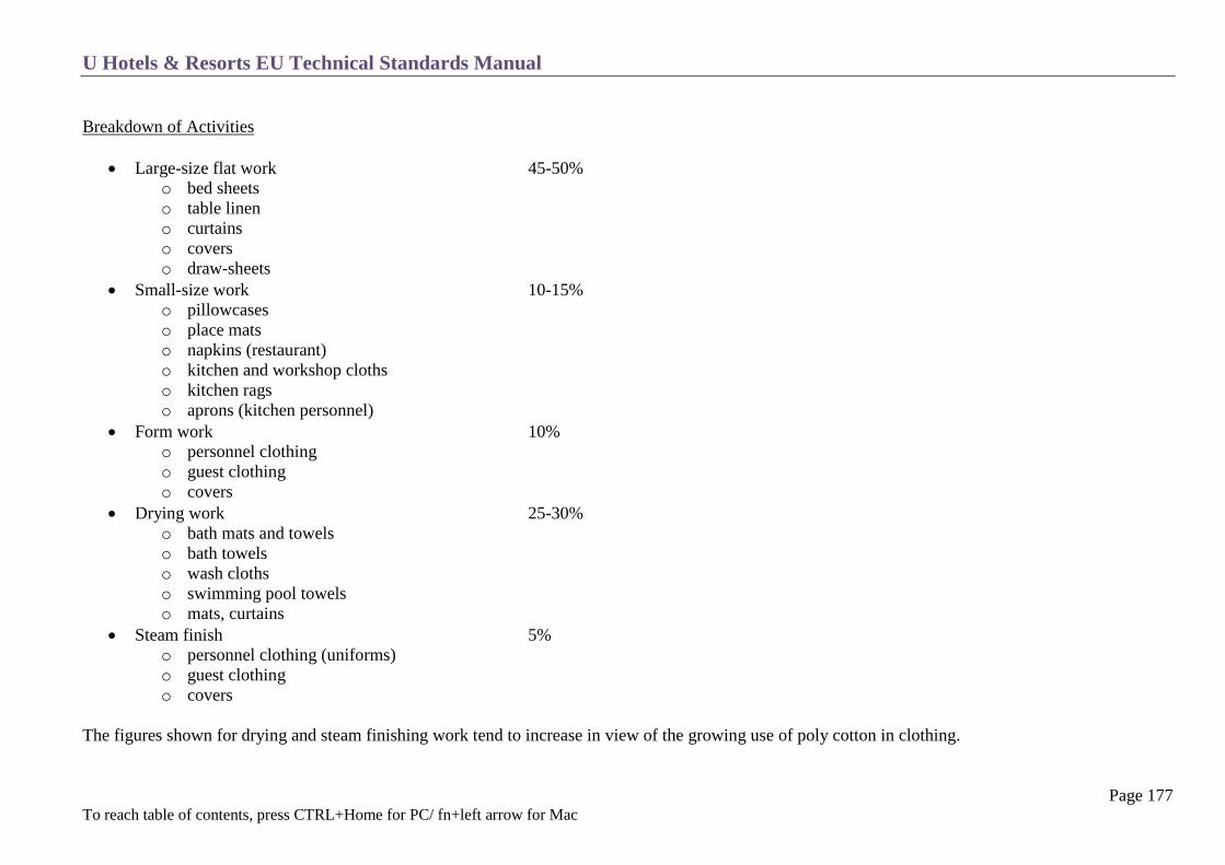
U Hotels & Resorts EU Technical Standards Manual
Page 177 To reach table of contents, press CTRL+Home for PC/ fn+left arrow for Mac
Breakdown of Activities
Large-size flat work 45-50%
o bed sheets
o table linen
o curtains
o covers
o draw-sheets
Small-size work 10-15%
o pillowcases
o place mats
o napkins (restaurant)
o kitchen and workshop cloths
o kitchen rags
o aprons (kitchen personnel)
Form work 10%
o personnel clothing
o guest clothing
o covers
Drying work 25-30%
o bath mats and towels
o bath towels
o wash cloths
o swimming pool towels
o mats, curtains
Steam finish 5%
o personnel clothing (uniforms)
o guest clothing
o covers
The figures shown for drying and steam finishing work tend to increase in view of the growing use of poly cotton in clothing.
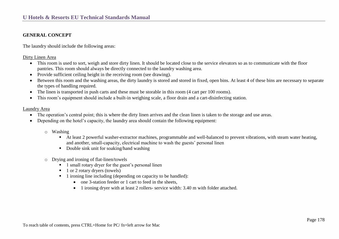
U Hotels & Resorts EU Technical Standards Manual
Page 178 To reach table of contents, press CTRL+Home for PC/ fn+left arrow for Mac
GENERAL CONCEPT
The laundry should include the following areas:
Dirty Linen Area
This room is used to sort, weigh and store dirty linen. It should be located close to the service elevators so as to communicate with the floor
pantries. This room should always be directly connected to the laundry washing area.
Provide sufficient ceiling height in the receiving room (see drawing).
Between this room and the washing areas, the dirty laundry is stored and stored in fixed, open bins. At least 4 of these bins are necessary to separate
the types of handling required.
The linen is transported in push carts and these must be storable in this room (4 cart per 100 rooms).
This room’s equipment should include a built-in weighing scale, a floor drain and a cart-disinfecting station.
Laundry Area
The operation’s central point; this is where the dirty linen arrives and the clean linen is taken to the storage and use areas.
Depending on the hotel’s capacity, the laundry area should contain the following equipment:
o Washing
At least 2 powerful washer-extractor machines, programmable and well-balanced to prevent vibrations, with steam water heating,
and another, small-capacity, electrical machine to wash the guests’ personal linen
Double sink unit for soaking/hand washing
o Drying and ironing of flat-linen/towels
1 small rotary dryer for the guest’s personal linen
1 or 2 rotary dryers (towels)
1 ironing line including (depending on capacity to be handled):
one 3-station feeder or 1 cart to feed in the sheets,
1 ironing dryer with at least 2 rollers- service width: 3.40 m with folder attached.

U Hotels & Resorts EU Technical Standards Manual
Page 179 To reach table of contents, press CTRL+Home for PC/ fn+left arrow for Mac
o Drying and ironing of various linen and form linen
1 group of shirt and cotton work clothing presses, or 1 mixed group, presses and shirt mannequin
1 general purpose press
1 or several professional ironing tables
o Miscellaneous
1 sewing machine
1 marking machine
o Handing/folding
Dirty laundry carts
storage bins or wheels (sorted linen)
clean wet laundry carts
rack carts to carry sorted flat linen and towels
mobile wardrobes form linen on hangers
folding tables for :
All small items
Towels
o Linen storage
Shelves, about 2.20 m high, 0.50 m wide, oven-baked finish or stainless-steel. See FFE list.
Laundry Manager’s office
o The Laundry Manager’s office must be located in this area. It should include a display phone and a computer terminal linked to the hotel’s
property management system (PMS).
Detergent storage room
o Used to store detergents and dry cleaning products with floor drain and appropriate ventilation.
Note = dangerous chemicals in significant quantities must be stored outside in a specific, protected area.
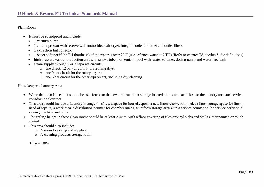
U Hotels & Resorts EU Technical Standards Manual
Page 180 To reach table of contents, press CTRL+Home for PC/ fn+left arrow for Mac
Plant Room
It must be soundproof and include:
1 vacuum pump
1 air compressor with reserve with mono-block air dryer, integral cooler and inlet and outlet filters
1 extraction lint collector
1 water softener if the TH (hardness) of the water is over 20˚F (use softened water at 7 TH) (Refer to chapter T8, section 8, for definitions)
high pressure vapour production unit with smoke tube, horizontal model with: water softener, dosing pump and water feed tank
steam supply through 2 or 3 separate circuits:
o one direct, 12 bar¹ circuit for the ironing dryer
o one 9 bar circuit for the rotary dryers
o one 6 bar circuit for the other equipment, including dry cleaning
Housekeeper’s Laundry Area
When the linen is clean, it should be transferred to the new or clean linen storage located in this area and close to the laundry area and service
corridors or elevators.
This area should include a Laundry Manager’s office, a space for housekeepers, a new linen reserve room, clean linen storage space for linen in
need of repairs, a work area, a distribution counter for chamber maids, a uniform storage area with a service counter on the service corridor, a
sewing machine and table.
The ceiling height in these clean rooms should be at least 2.40 m, with a floor covering of tiles or vinyl slabs and walls either painted or rough
coated.
This area should also include:
o A room to store guest supplies
o A cleaning products storage room
¹1 bar = 10Pa

U Hotels & Resorts EU Technical Standards Manual
Page 181 To reach table of contents, press CTRL+Home for PC/ fn+left arrow for Mac
The Executive Housekeeper’s office should open on the service corridor close to the linen distribution counter and if possible be located in a key part of the
laundry for effective supervision. It shall be glassed-in as much as possible for proper viewing of the surroundings. This office, as well as the
housekeeper’s space, shall be equipped with 2 display phones and a computer terminal linked to the hotel’s property management system (PMS).
Annexes
These rooms are also managed by the Executive Housekeeper:
o Floral preparation room
It should include a work bench, double sink and cold store/refrigerator.
o Mini-bar service room
It should include lockable cupboards with shelves.

U Hotels & Resorts EU Technical Standards Manual
Page 182 To reach table of contents, press CTRL+Home for PC/ fn+left arrow for Mac
TECHNICAL NOTES
The calculated live load on the floor must be at least 500 kg/m² with additional stresses due to the heavy equipment and vibrations.
Gutters with large grates, drains and filters must be provided for drainage of the washing machines.
All rooms must be equipped with smoke detectors (insurance classification: very dangerous).
Wall and floor coverings must be made of hard and washable materials with non-skid for the floors. It is preferable to tile the walls up to 2.10 m,
with protection angles on projection corners.
Avoid the use of drop ceilings.
The clearance height should incorporate the size of the machines and their eventual replacement (suggested minimum height: 4 m).
Provide waterproofing for the floors, floor drains, slope forms and gutter protection angle bars, particularly in front of the washing machines.
Provide sufficient space around the machines for maintenance access.
Storage areas must be at least 2.40 m high with fluorescent lighting and good air circulation.
The shelving units consist of 100 cm ling and 50 cm deep metal elements with rounded corners and no perforations, 5 shelves per unit.
The electrical installation must include an emergency stop button that stops all the rotating machines.
Each machine must be equipped with a visible shut-off selector switch.
The equipment must be of superior quality, officially approved by U Hotels & Resorts, and meet the following criteria:
304 L stainless steel
with adjustable base, mounted on anti-vibration stands of resilient material
with individual stopcocks
Heating-ventilation-air conditioning. See chapter T-11 Ventilation – Air conditioning
Particular attention must be given to the design of air supply and exhaust circuits to ensure the best possible working conditions and safety of dry
cleaning operations.
Notes:
Because of the forced extraction of the roll-ironer (hoods), rotary dryers and vacuum pump, it is imperative that their networks be separate from the
start, and then regrouped if necessary at the end of the line in a common duct under low pressure.
The presses, finishing tables and washing machine vents are under atmospheric pressure. A separate air extraction system must be installed next to
these machines.
The equipment size and type imply that the installation be as far away as possible from any public area. Especially avoid any installation of equipment
above public areas (see chapter C-21 Sound Control & Insulation).

U Hotels & Resorts EU Technical Standards Manual
Page 183 To reach table of contents, press CTRL+Home for PC/ fn+left arrow for Mac
TYPICAL LAYOUT
1 Washer-Extractor 60 kg. 2 Washer-Extractor 40 kg.
3 Washer-Extractor 25 kg.
4 Dryer 77 kg.
5 Dryer 55 kg.
6 Dryer 34 kg.
7 Flatwork Ironer 1 roll/
⌀ 500x3,200 mm
8 Form Finisher
9 Electric Steam Boiler with
Two Steam Irons
10 Vacuum Ironing Table
11 Single Bowl Sink
12 Working Table ( for Flatwork
linen)

U Hotels & Resorts EU Technical Standards Manual
Page 184 To reach table of contents, press CTRL+Home for PC/ fn+left arrow for Mac
PROTECTION OF THE ENVIRONMENT
In order to satisfy environmental protection requirements, the equipment must be selected according to the following criteria:
Minimum energy consumption (electricity, water and vapour)
Automatic programmable dosing of detergent products
Control of effluents and air pollution
Recuperation of toxic vapours (dry cleaning products in particular)
Limited noise pollution and vibrations
Whenever possible:
Re-utilisation of the last rinse water as first soaking water
Pre-treatment or treatment of wastewater

U Hotels & Resorts EU Technical Standards Manual
Page 185 To reach table of contents, press CTRL+Home for PC/ fn+left arrow for Mac
KITCHENS
General
Flow of Work
Design
Joinery – Glazing – Locksmithing
Waterproofing
Coverings
Plumbing Sanitation
Fire Protection
H V A C
Electricity
Low Voltage
Equipment
Main Kitchen
Display Kitchen
Employees Cafeteria
Bar Pantry
Pool Snack Bar Pantry
Satellite Kitchens

U Hotels & Resorts EU Technical Standards Manual
Page 186 To reach table of contents, press CTRL+Home for PC/ fn+left arrow for Mac
GENERAL
This concerns the preparation of dishes and the supply of drinks to all the distribution points in the hotel. This section includes the main kitchen as well as
the satellite kitchens and pantries described further on and communications with the sources of supply together with the service liaisons with the consumer
points.
The principle of forward movement shall be used in the organization of all food-service flows, in order to avoid any cross-contamination of foods with
different levels of hygiene.
Supplies
The goods arrive at the hotel at the receiving dock under the direction of the receiving office and are stored under the control of the storekeeper in the
following corresponding areas:
food supplies : food stores and cold storage rooms
beverages : beverage store and refrigerated beverage store
cleaning and other products : food stores + chemical products storage (bulk storage)
glass, porcelain, silverware : bulk storage and FFE store
The main kitchen receives all the goods according to the chef’s requirements from the storage area.
Transformation – Fabrication
As much as possible, most functions will be gathered in the main kitchen, in particular: main restaurant kitchen, room service and service bar.
All kitchen areas must be key-locked (in case all rooms are not on the same level, vertical means of circulation will be provided: goods elevators and
stairs).
Distribution
This is done directly from the main kitchen (s) or from satellite kitchens (functions, specialties).
The kitchen must be totally separable (doors with locks) from adjacent non-kitchen areas.

U Hotels & Resorts EU Technical Standards Manual
Page 187 To reach table of contents, press CTRL+Home for PC/ fn+left arrow for Mac
FLOW OF WORK
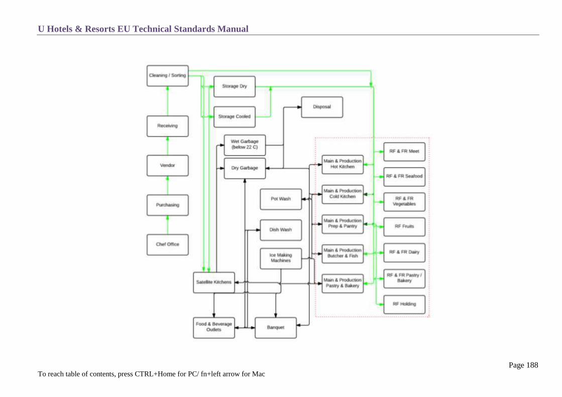
U Hotels & Resorts EU Technical Standards Manual
Page 188 To reach table of contents, press CTRL+Home for PC/ fn+left arrow for Mac

U Hotels & Resorts EU Technical Standards Manual
Page 189 To reach table of contents, press CTRL+Home for PC/ fn+left arrow for Mac
DESIGN
Module
Floors must be designed in consideration of the large number of holes needed for gutters, traps and piping and cold room recesses.
Dropped girders for the above and below floors should be avoided to facilitate the passage of ducts and piping (liquid waste, in particular).
Ducts and Pipes
In order to avoid maintenance problems, electrical boxes and piping and cables will not be left exposed but be integrated in technical shafts.
Recommended Ceiling Heights
Headroom between finished floor and ceilings (under beams, if applicable) should be a minimum of:
o Store room : 2800 mm minimum
o Kitchen : 3300 mm minimum
o Banquet satellite kitchen : 2800 mm minimum
Load Tolerance
At least the following floor loads should be taken into account in calculations for the concrete structure:
o Storeroom level : 600 kg/m²
o Kitchen level : 500 kg/m²
o Function satellite kitchen : 500 kg/m²

U Hotels & Resorts EU Technical Standards Manual
Page 190 To reach table of contents, press CTRL+Home for PC/ fn+left arrow for Mac
Circulations
Carts and trolleys shall be a maximum of 150 cm long × 90 cm wide.
All corridors, doors, service and freight elevators should be sized in accordance with these dimensions.
The minimum width of service corridors should be 1.60 m to 1.80 m.
Floors
There must be no steps between kitchens or in kitchens, including access to cold storage rooms (walk-in refrigerators and freezers), in order to
allow free circulation of trolleys.
Any differences in floor height can be compensated by ramps with a slope (not to exceed 4%).
Provisions for depressed slabs under cold rooms should be made from the beginning of the construction.
Partitions
Wall surfaces must be smooth, rot-proof, shock-resistant, watertight and easy to clean and disinfect. (See Section 6- coverings – below, and chapter
T7).
Partitions, doors, windows and ceilings must be resistant to humidity and high temperatures and allow easy cleaning.
Outside of air-conditioned areas, the partitions within the kitchen areas are generally 1.80m high at a minimum. They should be tiled to their full
height.
On a functional level, separate entrances must be provided for personnel, merchandise and trash, in compliance with the principle of separating
clean/soiled-handling areas as requested by food and beverage health regulations.
On the loading dock, goods receiving should be separate from the garbage area.

U Hotels & Resorts EU Technical Standards Manual
Page 191 To reach table of contents, press CTRL+Home for PC/ fn+left arrow for Mac
JOINERY – GLAZING – LOCKSMITHING
Large Windows
The following areas should be equipped with half- height glazed partitions:
Receiving office
Purchasing office
Storekeeper office
Executive Chef’s office
Between preparation areas
Between hot pastry and cold pastry (where applicable)
Service Hatches, Roller Blinds
To be provided:
Goods receiving: roller blinds
Main service bar : roller blind
Storekeeper : service hatch
Bar : roller blind
Doors
All service doors leading to kitchens and ancillary areas will be swinging doors (double doors where possible), with a passage width of 90 cm.
These doors will be fitted with a stainless steel plate 110 cm high with protection of stainless steel edge angles.
Doors leading to public areas must be metallic, or laminate-coated on both sides and fitted with kick plates. They should also have locks to control
area access when needed.
All doors will be equipped with automatic door closers.
Other doors will be finished with washable materials.
All doors in the vicinity of the kitchen, particularly those in communication with public areas, will be equipped with locks and bolts according to
the hotel-keying schedule.
All doors, (except those leading to public areas), will be outfitted with a square 30 × 30 cm oculus, and centred at 160 cm from the floor.
U Hotels & Resorts EU Technical Standards Manual
Page 192 To reach table of contents, press CTRL+Home for PC/ fn+left arrow for Mac
Air-lock
Two-way service vestibules will be installed between kitchens and public areas with a minimum width of 1.50 m.
These vestibules will be large enough to install the switchboxes for the electricity and sound system for the public areas.
Windows
Where possible natural light is needed.
All windows shall be fitted with washable insect screens
Anti-Trolley Wall Protection
All posts and protruding angles of kitchen partitions and service corridors should be equipped with stainless steel protection or rubber castors about
2 meters high.
For all kitchens aisles and freestanding walls, metallic channels measuring 15 cm high and 4 cm thick will be installed along the walls, 70 cm above
the finished floors.

U Hotels & Resorts EU Technical Standards Manual
Page 193 To reach table of contents, press CTRL+Home for PC/ fn+left arrow for Mac
WATERPROOFING
All floors in kitchens, pantries, storerooms, cellars and cold rooms should be sufficiently watertight to permit hosing down of the floor. A slope will
be included in the design for water evacuation. Expansion joints will be avoided in these zones, as well as close proximity with dangerous rooms
(transformer stations etc.).
The waterproofing and flashing shall be recessed into the wall (allowing kitchen equipment to be placed flush against wall).
Rounded-groove type baseboards are used to meet regulatory requirements.
Areas around the traps, gutters and sleeves should be perfectly watertight for the installation of water and electricity ducts.
These sleeves should be 5 cm above the finished floor and be filled with a watertight, resilient material.
Plan to install traps allowing evacuation of liquid waste around the watertight areas. Square and screwed special kitchen traps will be used.

U Hotels & Resorts EU Technical Standards Manual
Page 194 To reach table of contents, press CTRL+Home for PC/ fn+left arrow for Mac
COVERINGS
Floor Coverings
Floor level:
All floors will be flat, except for a very slight slope around the floor gutters and traps.
Stands:
Avoid heavy masonry pedestals for mounting kitchen equipment; instead use equipment (either free-standing on stainless-steel legs) against the
wall on a central beam or attached to the wall.
Materials:
The floors of kitchens and ancillary areas will be covered in 20 x 20 cm square-edge, 12 mm thick minimum non-slip stoneware tiles with rounded-
channel baseboards.
Foot Mats:
Large walk off mats (12 mm thick) will be recessed in the floor space of the service vestibules leading towards the public areas (from the kitchens).
Wall Coverings
All walls in kitchens and ancillary areas will be covered in top quality clay tiles in minimum size as of the floor tile, to the ceiling.
Use stainless steel plates on top of ceramic tiles behind heat sources.
Ceilings
If there are no suspended ceilings, ceilings will be painted with an easily-washable vinyl lacquer conforming to health standards.
In general, try to avoid passing ducts and pipes along kitchen ceilings to facilitate the cleaning process.
If ducts and pipes must be installed in this way they should be insulated or lagged and painted in the same manner as ceilings.
U Hotels & Resorts EU Technical Standards Manual
Page 195 To reach table of contents, press CTRL+Home for PC/ fn+left arrow for Mac
PLUMBING SANITATION
Energy Sources
Use gas for all cooking appliances, except for deep fat fryers, salamanders, steam ovens and cookers (with local steam production only). If tanks of
gas are used, plan to install tanks providing a minimum supply of 10 days.
Distribution
Water will be distributed at a pressure of 3 bar. Hot and cold water must be softened to a maximum ph of 7. Hot water will be distributed at a
minimum temperature of 50˚C using a circuit independent from that used for rooms and bathrooms.
Hot and cold water pipes: Minimum diameter is 15 mm, or 26 mm for large apparatus, with attachment by cylindrical brackets.
The whole distribution system should be concealed. Each supply line will end with an easily accessible stop valve (independent of the valve which
may already exist on the apparatus).
Drainage
They will be equipped with T-shaped clearing holes at each change in direction and along long straights.
Traps of gutters should be provided on major equipment and in each room, including beverages store, food store, cold rooms, garbage areas, etc.
The ground traps and gutters must be provided with removable dirt pans.
All gutters should have rounded corners to avoid deposits.
Drains will feed into a system comprising a mud collector, a grease trap and a starch decanting unit.
These fixtures will be located relatively far from the kitchens (to enable cooling down of grease), and will be easily accessible for cleaning. They
will be located outside the building or even in the parking areas.
A cold water spray with control system will be required to cool liquid wastes from the kitchen upstream of the grease traps.

U Hotels & Resorts EU Technical Standards Manual
Page 196 To reach table of contents, press CTRL+Home for PC/ fn+left arrow for Mac
Drainage Drawing

U Hotels & Resorts EU Technical Standards Manual
Page 197 To reach table of contents, press CTRL+Home for PC/ fn+left arrow for Mac
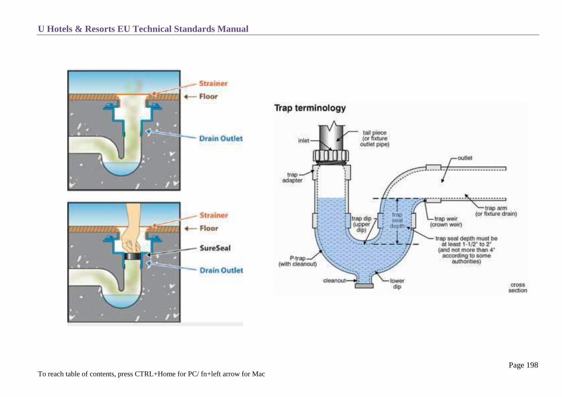
U Hotels & Resorts EU Technical Standards Manual
Page 198 To reach table of contents, press CTRL+Home for PC/ fn+left arrow for Mac

U Hotels & Resorts EU Technical Standards Manual
Page 199 To reach table of contents, press CTRL+Home for PC/ fn+left arrow for Mac
Gas
The gas installation must be in compliance with international standards or with local regulations if these are more restrictive.
A gas meter will be provided for each kitchen.
An easily-accessible gas pressure reducing and stop valve must be placed on the right-hand side of every gas appliance.
A master solenoid valve providing automatic cut-off as soon as excessive flow rate occurs. (i.e. a break in the pipe) will be placed at the entrance to
each kitchen and will allow cut-off of the main gas supply (punch stop).
At crucial areas like the gas plant and the hot kitchen gas detectors will need to be installed.
Hygiene
All kitchen areas shall be equipped with micro-spray units for cleaning and disinfection.
In the different kitchen zones hand wash washbasins shall be provided, along with soap and single-use towels dispensers.
Insect killers will be installed where appropriate.

U Hotels & Resorts EU Technical Standards Manual
Page 200 To reach table of contents, press CTRL+Home for PC/ fn+left arrow for Mac
FIRE PROTECTION
Fire protection comprises of two traditional systems:
o Portable fire extinguishers containing 9 kg of CO2
o Automatic CO2 or Inergen extinguishers installed in each exhaust hood are required.
Chapter T 9 Fire Protection and T 10 Fire Detection must be strictly followed. Provide an automatic gas cut-off solenoid valve activated with the hood
exhaust and with manual reset.

U Hotels & Resorts EU Technical Standards Manual
Page 201 To reach table of contents, press CTRL+Home for PC/ fn+left arrow for Mac
H V A C
General Conditions
All kitchens and ancillary areas should be ventilated and air-conditioned if necessary to maintain an indoor temperature of 26 ˚C, independent of
outdoor climatic conditions.
Relative humidity of these areas should be under 50%.
Furthermore, the following areas must be air-conditioned to make sure the inside temperature does not exceed 22˚ C: cold preparation-storage,
pastry-bakery (ovens in operation).
Double-flow hoods will be used.
The wine cellar should be kept at a maximum temperature of 18 ˚C (except for the refrigerated wine storeroom).
Ventilation
Minimum air renewal rate should be 25 volumes/hour for large kitchens and 30 volumes/hour for small kitchens unless calculations show that a
lower value will suffice.
Location of air diffusers should allow coverage of the whole area without creating “dead spots” where greasy vapour can build up.
Plan to blow fresh air through the exhaust hoods to create an air curtain around the hood.
The washing and work stations should be provided with enhanced ventilation.
Kitchens are kept at a lower pressure than the surrounding environment, in order to avoid odour propagation (air intake 90% of exhaust).
When new air comes partially from adjoining public areas, sound-insulation screens should be installed to avoid transmitting kitchen noises.
Two-speed exhaust systems should be installed to limit operating costs; controls will be kept near the Executive Chef’s office.
Care must be taken to ensure that the kitchen remains at a lower pressure than adjoining public areas when low exhaust speed is used.
Hoods
Hoods will be installed over all appliances releasing large quantities of heat, smoke and steam, i.e. range, kettles, dishwashing machines, pastry
ovens.
Hoods will be constructed of stainless steel (possibly other materials for “open display kitchens” e.g. glass or copper), and will be equipped with
vertical walls reaching to the ceiling to contain sudden releases of steam.
The lower edge will be 205 cm from the finished floor and this edge will be larger than appliance surfaces by 30 cm all the way around.
Watertight channels around the interior of the hoods will enable condensation recovery.

U Hotels & Resorts EU Technical Standards Manual
Page 202 To reach table of contents, press CTRL+Home for PC/ fn+left arrow for Mac
Air speed between stove and hood should be at least 0.15 m/sec.
Washable, easily removable grease filters should be installed above fryers, grills and broilers. Gutters should be installed under the grease filters.
At least two sets of filters will be provided.
Watertight, heat-resistant lights should be installed inside the hoods.
A pressure compensation system should be installed on exhaust systems fitted with grease filters to offset load losses due to the filters.
Ducts
Kitchen exhaust ducts should be made of galvanized steel (fire-resistant for at least 15 minutes), and watertight for cleaning (stapled ducts are
absolutely forbidden, use welded joints), sloped in the direction of air circulation and with a drain trap at the lowest point.
Monthly duct cleaning means that cleaning hatches measuring about 40 x 30 cm must be installed at all angles, every five meters on long straight
sections and at the base of every vertical section (with drain trap). Hatches should be fastened with stainless winged-nuts and casketed.
The bottom part of the horizontal ducts should have openings with internal flanges to avoid condensation drip.
Hood exhaust ducts should be insulated with high temperature insulation.
Avoid using pressure dampers which are difficult to clean.
Seek a natural balance in terms of calculation duct cross-sections.
Exhaust Fans
Exhaust fans must not be shared with other areas except for kitchens and pantries. They must have a two-speed motor located outside the air flow.
The exhaust registers must be far from windows and fresh air inlets and within a non-enclosed part of the building where it is protected from strong
winds.
Exhaust registers should be studied in order to avoid dirtying the façade
Exhaust motors create a lot of noise; due to this the location should be as far as possible from guest circulation areas.
U Hotels & Resorts EU Technical Standards Manual
Page 203 To reach table of contents, press CTRL+Home for PC/ fn+left arrow for Mac
ELECTRICITY
Lighting
Lighting for kitchen and ancillary areas will be controlled on a room-by-room basis, and will have 40% backup in all zones, including storage areas.
Kitchen lighting will be at 500 lux, storage zones at 100 lux and distribution and cashier areas at 750 lux.
Lighting will be provided by fluorescent tubes or LED as close as possible to a natural lighting environment.
Lights will be located in watertight fixtures, suspended a maximum of 2.60 meters above the finished floor or recessed into the ceiling.
The general power panel will be separated from the lighting panel.
Electrical Power Supply:
Each kitchen’s electrical power will be provided near the Executive Chef’s office (outside the office), or at a central point with one backed-up line
(grounded, three-phase + neutral) and a non-backed-up line (grounded, three-phase + neutral).
Depending on the climate, all equipment will be adapted accordingly particularly the contactor coils.
Sufficient power capacity (about 30%) will be provided to enable the addition of future complementary equipment. For this purpose, each
switchbox compartment will also be equipped with two contact breakers (4 × 10 A) and two contact breakers (4 × 20 A), with fuse-equipped
disconnectors. The kitchen should be provided with sufficient conductors and counter outlets to allow for an evolution and increase in the number
of equipment and power required.
Distribution:
Electrical distribution is through cable racks, routed under kitchen floors and behind wall tiles to a minimum height of 1.20 meters to the right of
each kitchen appliance.
Avoid placing outlets any lower because of the danger of water splashing.
Electrical distribution points should terminate in watertight circuit breakers placed to the right of each apparatus.
This is independent of the switches or disconnectors integral to the apparatus.
All switchboxes, electrical equipment and kitchen equipment must be grounded.
The circuits and outlets shall be adapted in terms of location, number, power and type to the equipment chosen for the kitchen layouts and studies.

U Hotels & Resorts EU Technical Standards Manual
Page 204 To reach table of contents, press CTRL+Home for PC/ fn+left arrow for Mac
Emergency Supply Circuits:
The following equipment must have backup supply:
Cold storage rooms
Refrigerators
Refrigerated cabinets and counters
Freezers
Ice machines
Kitchen exhaust fans
At least one stove, to enable basic cooking
For all-electric kitchens, the following equipment should also be backed up to allow minimum food and beverage service:
1 oven
1 broiler
1 bain-marie
1 fryer
1 overhead grill (salamander)
Outlets:
Besides the specific outlets for kitchen equipment, all electrical outlets will be watertight units 1.20 meters above the finished floor in the various
kitchens, pantries and storage rooms. These outlets must be grounded.
Catering satellite kitchens should be equipped with at least six outlets, each rated at 3 000 W, taking special plugs.
These outlets should be recessed in the wall to allow connection of cold n hot and hold ‘n serve banquet trolleys.
Special outlets connected to emergency power supplies should be installed for the POS (restaurants, bar and room-service).
These outlets will be connected directly to the switchboxes on each floor (to avoid voltage drops), and should correspond to the specific needs of
selected equipment (special case: data processing equipment requiring an inverter).

U Hotels & Resorts EU Technical Standards Manual
Page 205 To reach table of contents, press CTRL+Home for PC/ fn+left arrow for Mac
LOW VOLTAGE
Property Management System
The equipment shall be defined according to the U Hotels & Resorts Hotel Brief.
In the kitchen zones, “order-taker” terminal P.O.S. system printers shall be provided for the service bar, cold prep and central cooking distribution.
In certain areas (room-service, food-store, cashiers chef’s office) emergency-supplied double power outlets shall be provided as well as RJ 45
outlets with CAT 6 cables to connect to the PMS and POS.
Telephones
The following telephone sets should be installed:
One wall-mounted set in each kitchen section and in the pastry-bakery.
One desktop set plus separate RJ 45 (CAT 6) outlet in:
o Executive Chef’s office
o Receiving office
o Purchasing office
Two or three sets in an extension hunting group, answering one-digit calls for the Room Service (Your Dining) office if applicable.
These sets will be equipped with headsets and can be forwarded to another set for night service.
Each set will have a screen for display of the internal calling unit and display of calling party data.
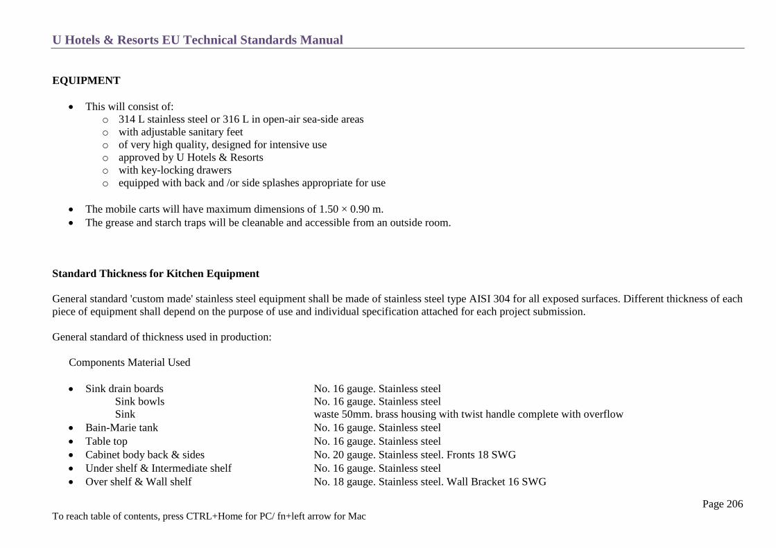
U Hotels & Resorts EU Technical Standards Manual
Page 206 To reach table of contents, press CTRL+Home for PC/ fn+left arrow for Mac
EQUIPMENT
This will consist of:
o 314 L stainless steel or 316 L in open-air sea-side areas
o with adjustable sanitary feet
o of very high quality, designed for intensive use
o approved by U Hotels & Resorts
o with key-locking drawers
o equipped with back and /or side splashes appropriate for use
The mobile carts will have maximum dimensions of 1.50 × 0.90 m.
The grease and starch traps will be cleanable and accessible from an outside room.
Standard Thickness for Kitchen Equipment
General standard 'custom made' stainless steel equipment shall be made of stainless steel type AISI 304 for all exposed surfaces. Different thickness of each
piece of equipment shall depend on the purpose of use and individual specification attached for each project submission.
General standard of thickness used in production:
Components Material Used
Sink drain boards No. 16 gauge. Stainless steel
Sink bowls No. 16 gauge. Stainless steel
Sink waste 50mm. brass housing with twist handle complete with overflow
Bain-Marie tank No. 16 gauge. Stainless steel
Table top No. 16 gauge. Stainless steel
Cabinet body back & sides No. 20 gauge. Stainless steel. Fronts 18 SWG
Under shelf & Intermediate shelf No. 16 gauge. Stainless steel
Over shelf & Wall shelf No. 18 gauge. Stainless steel. Wall Bracket 16 SWG
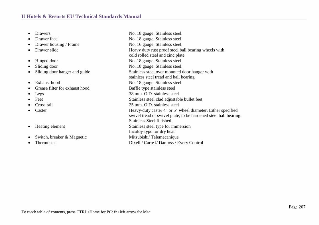
U Hotels & Resorts EU Technical Standards Manual
Page 207 To reach table of contents, press CTRL+Home for PC/ fn+left arrow for Mac
Drawers No. 18 gauge. Stainless steel.
Drawer face No. 18 gauge. Stainless steel.
Drawer housing / Frame No. 16 gauge. Stainless steel.
Drawer slide Heavy duty rust proof steel ball bearing wheels with
cold rolled steel and zinc plate
Hinged door No. 18 gauge. Stainless steel.
Sliding door No. 18 gauge. Stainless steel.
Sliding door hanger and guide Stainless steel over mounted door hanger with
stainless steel tread and ball bearing
Exhaust hood No. 18 gauge. Stainless steel.
Grease filter for exhaust hood Baffle type stainless steel
Legs 38 mm. O.D. stainless steel
Feet Stainless steel clad adjustable bullet feet
Cross rail 25 mm. O.D. stainless steel
Caster Heavy-duty caster 4" or 5" wheel diameter. Either specified
swivel tread or swivel plate, to be hardened steel ball bearing.
Stainless Steel finished.
Heating element Stainless steel type for immersion
Incoloy-type for dry heat
Switch, breaker & Magnetic Mitsubishi/ Telemecanique
Thermostat Dixell / Carre l/ Danfoss / Every Control

U Hotels & Resorts EU Technical Standards Manual
Page 208 To reach table of contents, press CTRL+Home for PC/ fn+left arrow for Mac
MAIN KITCHEN
General Criteria
This is located in direct contact with all the food-distribution outlets and, if possible, all the beverage distribution points.
It should be linked with the storages, cold rooms and stores via means providing for easy circulation (whether corridors or goods elevators).
The number of ancillary kitchens will be limited as far as possible.
The different parts of the main kitchen are:
Daily stores (cold rooms) see section C 16
Fruit and vegetable preparation
Fish preparation
Meat preparation
Central cooking zone
Cold preparation
Buffets preparation
Bakery-pastry
Room-service
Dish washing
Utensils pot washing
Service bar
Banquet kitchen
Chef’s office
Note: the main service bar may, in some instances, be coupled with the room service.
Cold room
Food store
Order taker
Cafeteria kitchen

U Hotels & Resorts EU Technical Standards Manual
Page 209 To reach table of contents, press CTRL+Home for PC/ fn+left arrow for Mac
Areas
As indicated in the hotel brief, they are a first approach which must be adapted to each building’s constraints and each project in particular.
Schematic drawings are attached for each zone, as a checklist and guideline. However, for each project, the layouts and equipment lists can only be the
result of a specific study by a specialized kitchen consultant.
Description of Zones:
Note = In some cases, a pre-treatment area (before storage) will be provided at the same level as the loading dock.
Fruit and Vegetable Preparation:
This receives the raw products from the storage area. Here all the fruit and vegetables are cleaned and prepared.
Once prepared, the products are stored in the cold room reserved for fruit and vegetables ready for use.
Meat and Fish Preparation:
The meat and fish are cleaned and cut up, after which they are stored in the cold room and fish drawers until they are used by the chef.
This zone is air-conditioned and kept at 22 ˚C.
Central Cooking Zone:
This is the most important zone in the main kitchen and contains all the equipment necessary to cook food. It prepares and finishes the hot dishes. It
receives the pieces ready to cook from the cold rooms and preparation zone. It receives the clean kitchen utensils from the utensils washing.
It receives clean plates from the dish washing area.
It distributes the cooked dishes via the distribution counter, which has a plate heater counter.
The Chef’s office should be located alongside and in visual contact with this zone.
A hood with ventilation covers the whole cooking zone.
Heated shelves for plates.
Infrared lamps for the hot dishes on the counter pass shelves.

U Hotels & Resorts EU Technical Standards Manual
Page 210 To reach table of contents, press CTRL+Home for PC/ fn+left arrow for Mac
Cold Preparation:
Receives the food prepared in the preparation zones and products such as dairy items directly from the cold storage rooms. These products are then
stored in refrigerators.
The chinaware arrives in this zone from the dishwashing area.
Prepares the cold dishes such as salads, sandwiches and seafood.
Distributes these cold dishes across a counter.
Bakery-Pastry:
Receives the products directly from the general store and stores them in its own cold rooms. Also receives the pots, dishes and moulds from the
utensils washing area.
It produces bread, pastry, croissants, etc. and stores them in carts, portable baskets and in its own cold rooms.
Hot and cold sections shall be kept separate. The cold section is fully air-conditioned at 22C.
Room Service (Your Dining):
In direct contact with the service corridors or elevators servicing the bedroom levels.
Unless impossible, it should be located close to the all-day dining restaurant and be part of the main kitchen. It receives the food from almost all the
kitchen zones.
Prepares the breakfasts.
Lays the dishes on the service tables.
Stores certain products in its own cabinets and refrigerators.
Centralized the orders to be served in the rooms.
Distributes its production via service elevators to the rooms on service tables, carts and trays and stores all of the latter equipment.
Sends all the soiled ware to the dish washing area.
Requires a telephone and a P.O.S. terminal, a cash register station and work posts for taking orders.
A refrigerated food reserve will be provided for night service.
Note that, in a traditional business hotel, more than 15% of guests use this service for breakfast.

U Hotels & Resorts EU Technical Standards Manual
Page 211 To reach table of contents, press CTRL+Home for PC/ fn+left arrow for Mac
Dishwashing Area:
This zone receives all the dirty ware (chinaware, glass silver) on a special sorting table from all the outlets connected with the kitchen and Room
Service (Your Dining).
Once clean, the ware is stored on shelves and distributed on carts between the different services:
o Room Service (Your Dining)
o Cold preparation service
o Central cooking zone
o Service bar
o Catering pantry (and other pantries, if any)
o Steward store
Utensils Pot Washing
Receives all the pots and all utensils from the central cooking zone, preparation zone, bakery and pastry.
The utensils are washed and repaired there before returning them to the zone where they are used.
One of the sinks shall be equipped with an adjustable heating system.
Service Bar:
Its function is to distribute the wines, liquors and other beverages to the restaurants and reception rooms.
It receives clean glasses from the dishwashing area, distributes the beverages in bottles or glasses over a counter, recovers all the empty bottles for
control and sends them to the empty bottles storage area for recycling.
Banquet Satellite Kitchen
It is always necessary to serve all the reception rooms, whatever their situation in relation to the main kitchen.
All the dishes, prepared in large quantities in the main kitchen, should be served at the same time and kept hot or cold in the banquet satellite
kitchen on portable carts (in special stores, or plug-in).
Sufficient space should be provided in this area to store the service carts and also a coffee preparation zone and service bar. If the reception rooms
are far from the main kitchen or are located on another level, a dish washing zone will be provided.
The banquet kitchen must be linked to the reception rooms by a corridor separate from the public corridors.
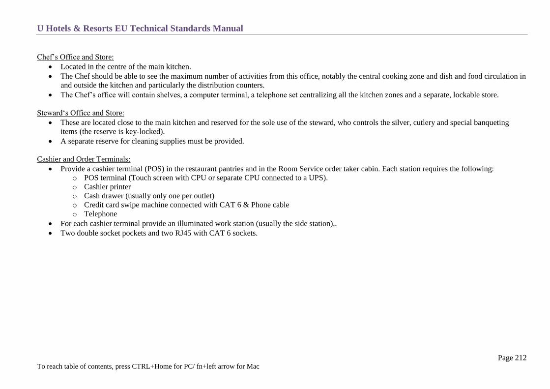
U Hotels & Resorts EU Technical Standards Manual
Page 212 To reach table of contents, press CTRL+Home for PC/ fn+left arrow for Mac
Chef’s Office and Store:
Located in the centre of the main kitchen.
The Chef should be able to see the maximum number of activities from this office, notably the central cooking zone and dish and food circulation in
and outside the kitchen and particularly the distribution counters.
The Chef’s office will contain shelves, a computer terminal, a telephone set centralizing all the kitchen zones and a separate, lockable store.
Steward‘s Office and Store:
These are located close to the main kitchen and reserved for the sole use of the steward, who controls the silver, cutlery and special banqueting
items (the reserve is key-locked).
A separate reserve for cleaning supplies must be provided.
Cashier and Order Terminals:
Provide a cashier terminal (POS) in the restaurant pantries and in the Room Service order taker cabin. Each station requires the following:
o POS terminal (Touch screen with CPU or separate CPU connected to a UPS).
o Cashier printer
o Cash drawer (usually only one per outlet)
o Credit card swipe machine connected with CAT 6 & Phone cable
o Telephone
For each cashier terminal provide an illuminated work station (usually the side station),.
Two double socket pockets and two RJ45 with CAT 6 sockets.
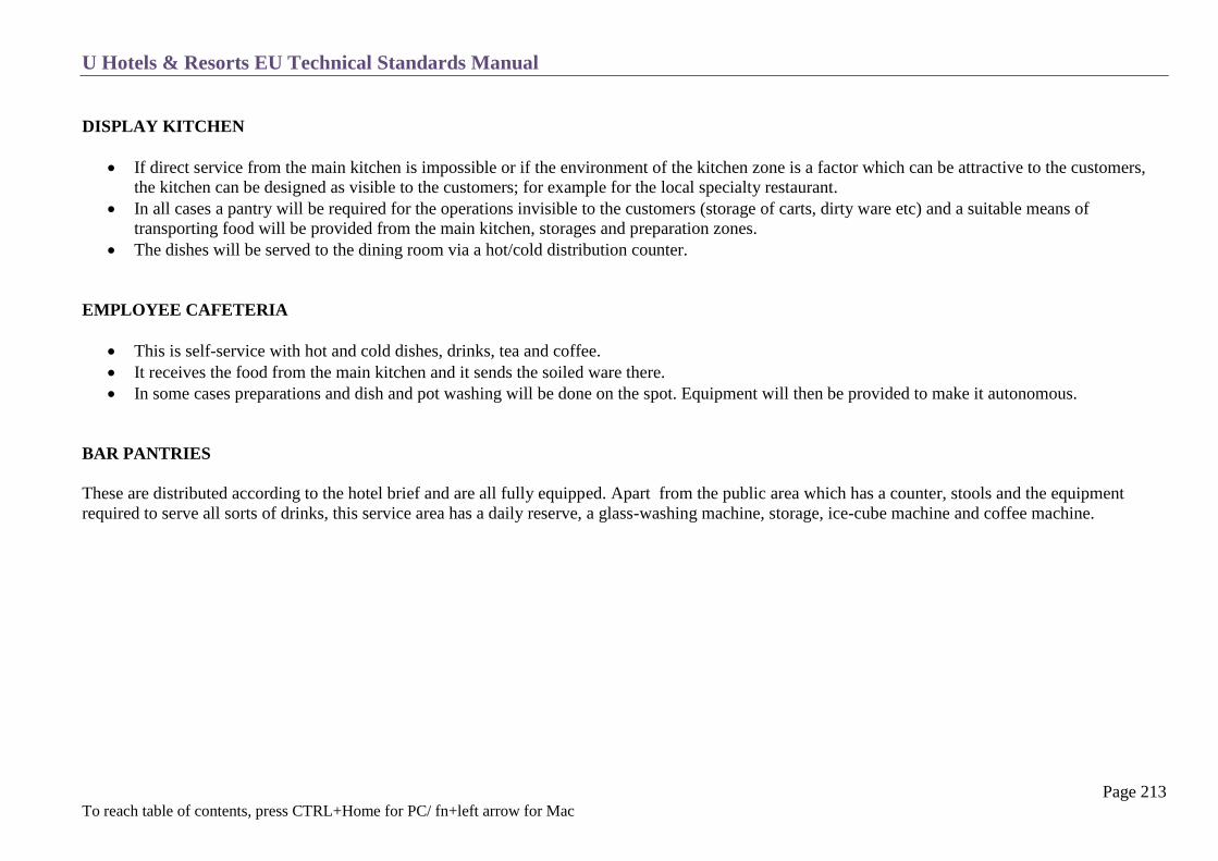
U Hotels & Resorts EU Technical Standards Manual
Page 213 To reach table of contents, press CTRL+Home for PC/ fn+left arrow for Mac
DISPLAY KITCHEN
If direct service from the main kitchen is impossible or if the environment of the kitchen zone is a factor which can be attractive to the customers,
the kitchen can be designed as visible to the customers; for example for the local specialty restaurant.
In all cases a pantry will be required for the operations invisible to the customers (storage of carts, dirty ware etc) and a suitable means of
transporting food will be provided from the main kitchen, storages and preparation zones.
The dishes will be served to the dining room via a hot/cold distribution counter.
EMPLOYEE CAFETERIA
This is self-service with hot and cold dishes, drinks, tea and coffee.
It receives the food from the main kitchen and it sends the soiled ware there.
In some cases preparations and dish and pot washing will be done on the spot. Equipment will then be provided to make it autonomous.
BAR PANTRIES
These are distributed according to the hotel brief and are all fully equipped. Apart from the public area which has a counter, stools and the equipment
required to serve all sorts of drinks, this service area has a daily reserve, a glass-washing machine, storage, ice-cube machine and coffee machine.

U Hotels & Resorts EU Technical Standards Manual
Page 214 To reach table of contents, press CTRL+Home for PC/ fn+left arrow for Mac
POOL SNACK BAR PANTRY
The swimming pool snack bar is located adjacent or close to the pool. It contains a satellite kitchen capable of preparing and serving a limited
number of simple hot or cold dishes and all drinks.
All the food comes from the main kitchen.
The dishes are served on the counter and at the tables around the pool. A daily food and drinks store is added with a dishwasher, the service section
being concealed from the public.
SATELLITE KITCHENS
These are kitchens designed to receive prepared dishes from the main kitchen and preserve them in ideal conditions as well as prepare their own
specialized dishes, to be served at special consumption points such as meeting rooms, cocktail parties, and specialty restaurants.
Hot and cold trolley storage must therefore be provided and the equipment necessary to serve coffee and drinks, as well as reduced storage,
preparing and cooking equipment.
In certain cases (regional cooking or a considerable distance from the main kitchen for example), it is necessary to provide full storage, preparation,
cooking and dishwashing zones.

U Hotels & Resorts EU Technical Standards Manual
Page 215 To reach table of contents, press CTRL+Home for PC/ fn+left arrow for Mac
LAYOUTS
SMALL TO MEDIUM HOTEL KITCHEN

U Hotels & Resorts EU Technical Standards Manual
Page 216 To reach table of contents, press CTRL+Home for PC/ fn+left arrow for Mac
MEAT AND FISH PREPARATION
K Butcher (Meat & Poultry)

U Hotels & Resorts EU Technical Standards Manual
Page 217 To reach table of contents, press CTRL+Home for PC/ fn+left arrow for Mac
MEAT AND FISH PREPARATION
K- BUTCHER (SEAFOOD) BG-MEAT WALK-IN CHILLER
K-01 Single Bowl Sink Unit BG-01 Meat Panel Type Cold Room
K-02 Fish Preparation Table With Double Sink BG-02 Shelving Unit
K-03 Spray Unit BH-POULTRY WALK-IN CHILLER
K-04 Waste Bin BH-01 Poultry Panel Type Cold Room
K-05 Working Bench BH-02 Shelving Unit
K-06 Scale BF-SEAFOOD WALK-IN CHILLER
K-07 Double Wall Shelf BF-01 Seafood Panel Type Cold Room
K-08 Counter Type Refrigerator BF-02 Shelving Unit
K-09 Double Wall Shelf BF-03 Shelving Unit
K-10 Double Bowl Sink Unit BE- WALK-IN FREEZER
K-11 Spare Number BE-01 Panel Type Deep Freezer
K-12 Counter Type Refrigerator BE-02 Shelving Unit
K-13 Bone Saw Machine M-POT-WASH AREA
K-14 Meat Mincing Machine M-01 Shelving Unit
K-15 Universal Machine Um 12 M-02 Working Bench
K-16 Working Bench M-03 Three Bowl Sink Unit
K-17 Wall Shelf M-04 Waste Bin
K-18 Double Bowl Sink Unit M-05 Spray Unit
K-19 Hand Wash Sink Unit M-06 Hand Wash Sink Unit
K-20 Pre-Wash Hose M-07 Pre-Wash Hose 10 Mt
K-21 Double Bowl Sink Unit M-08 Pot Carrying Trolley
K-22 Vacuum Machine Y-FLOOR THROUGH
K-23 Universal Machine Um 44 Y-01 Floor Through
Y-02 Floor Through
Y-03 Floor Through
Y-04 Insect Killer

U Hotels & Resorts EU Technical Standards Manual
Page 218 To reach table of contents, press CTRL+Home for PC/ fn+left arrow for Mac
VEGETABLE PREPARATION
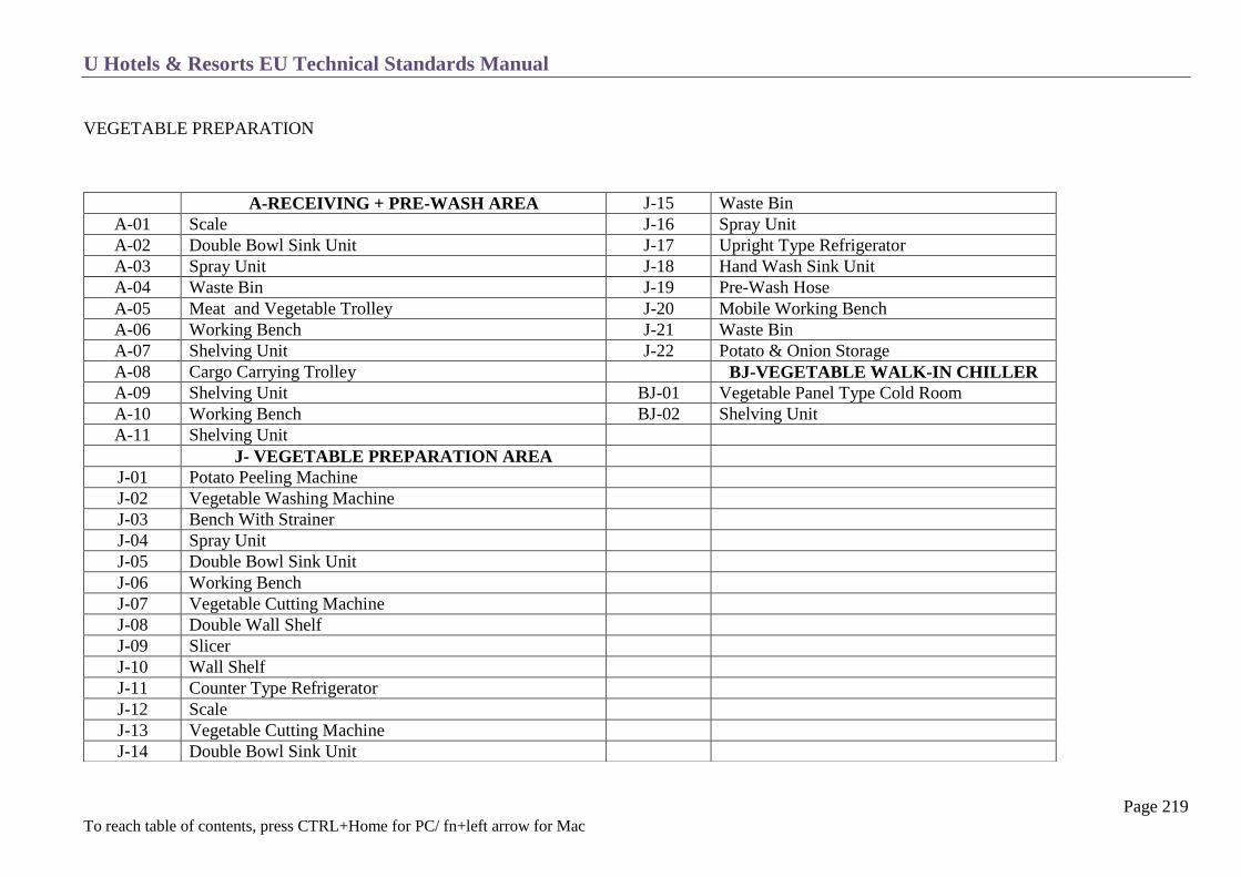
U Hotels & Resorts EU Technical Standards Manual
Page 219 To reach table of contents, press CTRL+Home for PC/ fn+left arrow for Mac
VEGETABLE PREPARATION
A-RECEIVING + PRE-WASH AREA J-15 Waste Bin
A-01 Scale J-16 Spray Unit
A-02 Double Bowl Sink Unit J-17 Upright Type Refrigerator
A-03 Spray Unit J-18 Hand Wash Sink Unit
A-04 Waste Bin J-19 Pre-Wash Hose
A-05 Meat and Vegetable Trolley J-20 Mobile Working Bench
A-06 Working Bench J-21 Waste Bin
A-07 Shelving Unit J-22 Potato & Onion Storage
A-08 Cargo Carrying Trolley BJ-VEGETABLE WALK-IN CHILLER
A-09 Shelving Unit BJ-01 Vegetable Panel Type Cold Room
A-10 Working Bench BJ-02 Shelving Unit
A-11 Shelving Unit
J- VEGETABLE PREPARATION AREA
J-01 Potato Peeling Machine
J-02 Vegetable Washing Machine
J-03 Bench With Strainer
J-04 Spray Unit
J-05 Double Bowl Sink Unit
J-06 Working Bench
J-07 Vegetable Cutting Machine
J-08 Double Wall Shelf
J-09 Slicer
J-10 Wall Shelf
J-11 Counter Type Refrigerator
J-12 Scale
J-13 Vegetable Cutting Machine
J-14 Double Bowl Sink Unit
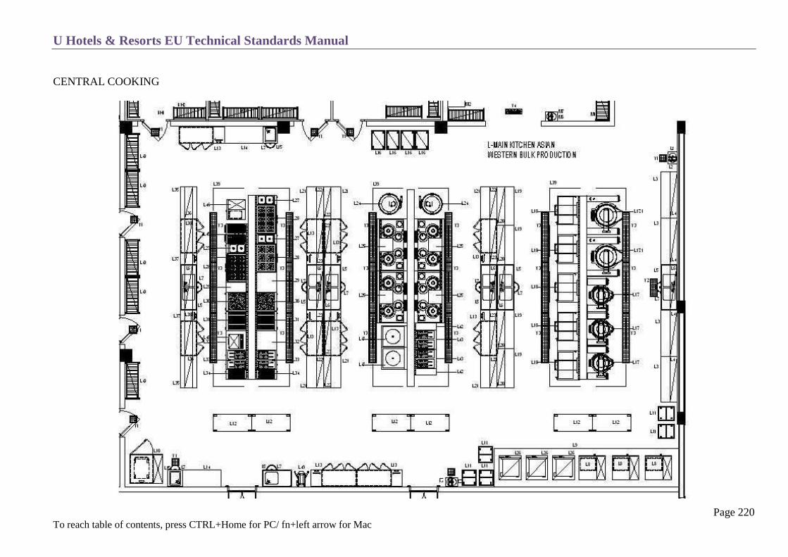
U Hotels & Resorts EU Technical Standards Manual
Page 220 To reach table of contents, press CTRL+Home for PC/ fn+left arrow for Mac
CENTRAL COOKING

U Hotels & Resorts EU Technical Standards Manual
Page 221 To reach table of contents, press CTRL+Home for PC/ fn+left arrow for Mac
CENTRAL COOKING
L-01 Pre-Wash Hose L-25 Wok Cooker
L-02 Hand Wash Sink Unit L-26 Rice Warmer
L-03 Working Bench L-27 Bain Marie
L-04 Double Wall Shelf L-28 Cooker
L-05 Double Bowl Sink Unit L-29 Working Bench
L-06 Double Wall Shelf L-30 Grill Plate
L-07 Waste Bin L-31 Grill Plate
L-08 Convection Oven L-32 Working Bench
L-09 Wall Type Hood L-33 Fryer
L-10 Blast Chiller L-34 Chip Scuttles
L-11 Tray Trolley L-35 Working Bench
L-12 Mobile Top Bench L-36 Service Shelf
L-13 Counter Type Refrigerator L-37 Counter Type Refrigerator
L-14 Working Bench L-38 Double Wall Shelf
L-15 Single Bowl Sink Unit L-39 Island Type Hood
L-16 Tray Trolley L-40 Shelving Unit
L-17 Tilting Boiling Pan (150lt) L-41 Spare Number
L-17.1 Tilting Boiling Pan (250lt) L-42 Working Bench
L-18 Tilting Bratt Pan L-43 Fryer
L-19 Working Bench L-44 Spare Number
L-20 Double Wall Shelf L-45 Pasta Cooker
L-21 Working Bench L-46 Convection Oven
L-22 Double Wall Shelf L-47 Dim Sum Steamer
L-23 Double Wall Shelf L-48 Salamander
L-24 Duck Roster L-49 Mixer
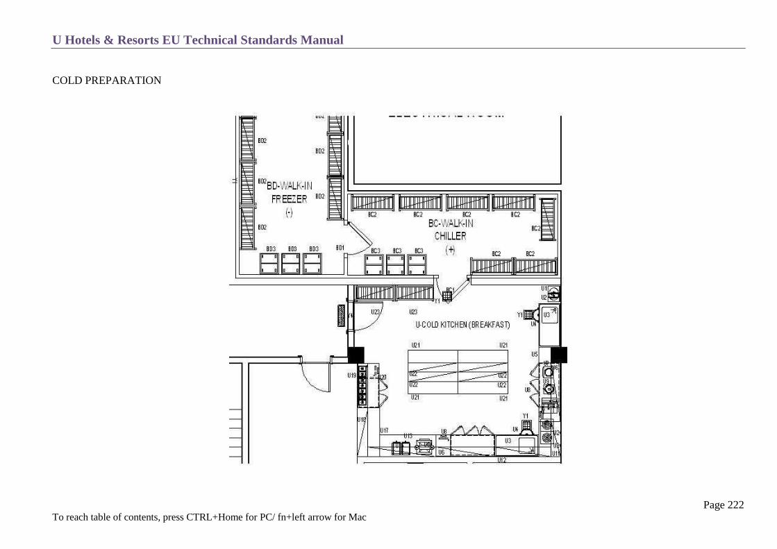
U Hotels & Resorts EU Technical Standards Manual
Page 222 To reach table of contents, press CTRL+Home for PC/ fn+left arrow for Mac
COLD PREPARATION

U Hotels & Resorts EU Technical Standards Manual
Page 223 To reach table of contents, press CTRL+Home for PC/ fn+left arrow for Mac
COLD PREPARATION
BC -WALK-IN CHILLER U-09 Vegetable Cutter Machine
BC-01 Panel Type Cold Room U-10 Slicer
BC-02 Shelving Unit U-11 Wall Shelf
BC-03 Tray Trolley U-12 Scale
BD -WALK-IN FREEZER U-13 Working Bench
BD-01 Panel Type Deep Freezer U-14 Citrus Juicer Machine
BD-02 Shelving Unit U-15 Toaster Machine
BD-03 Tray Trolley U-16 Spare Number
U – COLD KITCHEN (BREAKFAST) U-17 Working Bench
U-01 Hand Wash Sink Unit U-18 Double Wall Shelf
U-02 Pre-Wash Hose U-19 Wall Shelf & Prep Unit
U-03 Single Bowl Sink Unit U-20 Counter Type Refrigerator
U-04 Waste Bin U-21 Working Bench
U-05 Working Bench U-22 Service Shelf
U-06 Wall Shelf U-23 Shelving Unit
U-07 Scale U-24 Induction Cooker
U-08 Counter Type Refrigerator

U Hotels & Resorts EU Technical Standards Manual
Page 224 To reach table of contents, press CTRL+Home for PC/ fn+left arrow for Mac
BAKERY / PASTRY / ICE CREAM
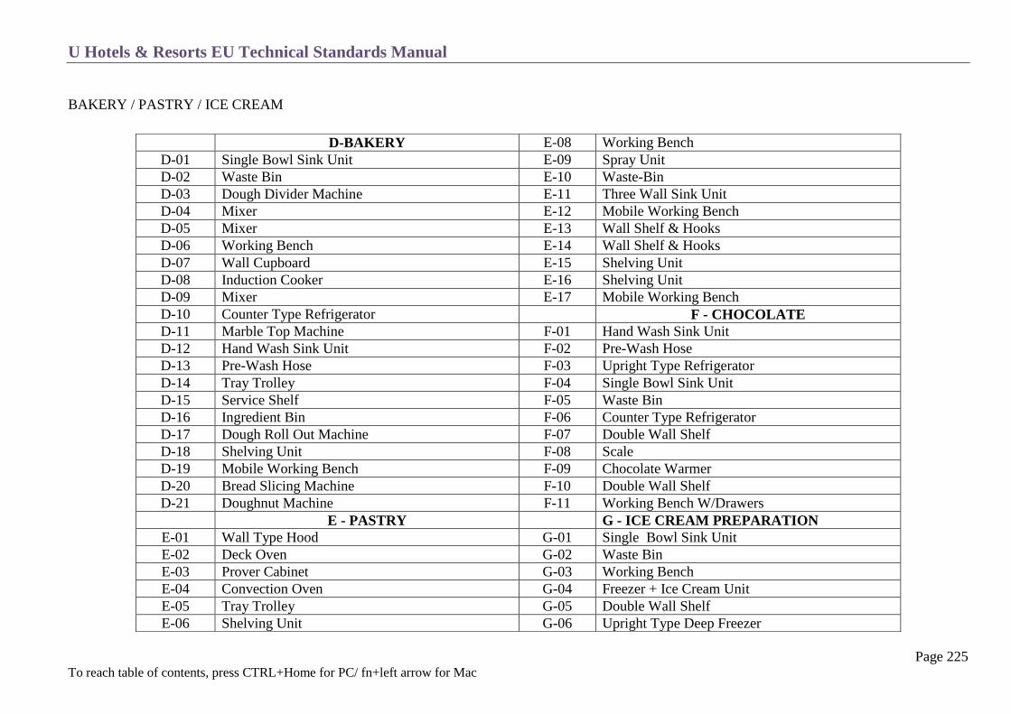
U Hotels & Resorts EU Technical Standards Manual
Page 225 To reach table of contents, press CTRL+Home for PC/ fn+left arrow for Mac
BAKERY / PASTRY / ICE CREAM
D-BAKERY E-08 Working Bench
D-01 Single Bowl Sink Unit E-09 Spray Unit
D-02 Waste Bin E-10 Waste-Bin
D-03 Dough Divider Machine E-11 Three Wall Sink Unit
D-04 Mixer E-12 Mobile Working Bench
D-05 Mixer E-13 Wall Shelf & Hooks
D-06 Working Bench E-14 Wall Shelf & Hooks
D-07 Wall Cupboard E-15 Shelving Unit
D-08 Induction Cooker E-16 Shelving Unit
D-09 Mixer E-17 Mobile Working Bench
D-10 Counter Type Refrigerator F - CHOCOLATE
D-11 Marble Top Machine F-01 Hand Wash Sink Unit
D-12 Hand Wash Sink Unit F-02 Pre-Wash Hose
D-13 Pre-Wash Hose F-03 Upright Type Refrigerator
D-14 Tray Trolley F-04 Single Bowl Sink Unit
D-15 Service Shelf F-05 Waste Bin
D-16 Ingredient Bin F-06 Counter Type Refrigerator
D-17 Dough Roll Out Machine F-07 Double Wall Shelf
D-18 Shelving Unit F-08 Scale
D-19 Mobile Working Bench F-09 Chocolate Warmer
D-20 Bread Slicing Machine F-10 Double Wall Shelf
D-21 Doughnut Machine F-11 Working Bench W/Drawers
E - PASTRY G - ICE CREAM PREPARATION
E-01 Wall Type Hood G-01 Single Bowl Sink Unit
E-02 Deck Oven G-02 Waste Bin
E-03 Prover Cabinet G-03 Working Bench
E-04 Convection Oven G-04 Freezer + Ice Cream Unit
E-05 Tray Trolley G-05 Double Wall Shelf
E-06 Shelving Unit G-06 Upright Type Deep Freezer

U Hotels & Resorts EU Technical Standards Manual
Page 226 To reach table of contents, press CTRL+Home for PC/ fn+left arrow for Mac
MAIN KITCHEN
H – DOUGH AREA BM – WALK-IN CHILLER
H-01 Single Bowl Sink Unit BM-01 Panel Type Cold Room
H-02 Waste Bin BM-02 Shelving Unit
H-03 Mixer BM-03 Mobile Working Bench
H-04 Mixer BN – WALK –IN CHILLER
H-05 Working Bench BN-01 Panel Type Cold Room
H-06 Double Wall Shelf BN-02 Shelving Unit
H-07 Double Wall Shelf BN-03 Mobile Working Bench
H-08 Counter Type Refrigerator BO – WALK-IN FREEZER PASTRY
H-09 Scale BO-01 Pastry Panel Type Deep Freezer
H-10 Working Bench BO-02 Shelving Unit
H-11 Mixer BO-03 GN 2/1 Tray Trolley
H-12 Double Wall Shelf
H-13 Marble Top Bench
H-14 Service Shelf
H-15 Ingredient Bin
H-16 Hand Wash Sink Unit
H-17 Pre-Wash Hose
H-18 Double Wall Shelf

U Hotels & Resorts EU Technical Standards Manual
Page 227 To reach table of contents, press CTRL+Home for PC/ fn+left arrow for Mac

U Hotels & Resorts EU Technical Standards Manual
Page 228 To reach table of contents, press CTRL+Home for PC/ fn+left arrow for Mac

U Hotels & Resorts EU Technical Standards Manual
Page 229 To reach table of contents, press CTRL+Home for PC/ fn+left arrow for Mac
POTS AND PANS
M-01 Shelving Unit
M-02 Working Bench
M-03 Three Bowl Sink Unit
M-04 Waste Bin
M-05 Spray Unit
M-06 Hand Wash Sink Unit
M-07 Pre-Wash Hose 10 Mt.
M-08 Pot Carry

U Hotels & Resorts EU Technical Standards Manual
Page 230 To reach table of contents, press CTRL+Home for PC/ fn+left arrow for Mac
DISHWASHING AREA
DW-01 L-Shape Dirty Dish Table w/ Drop off Station
DW-02 Mobile Plastic Garbage Bin
DW-03 Over Rack Shelf
DW-04 Pre-Rinse Unit
DW-05 Ventilator w/fresh Air Return (body only)
DW-06 Floor Channel & Gully w/ Grating
DW-07 Hood Type Dish Washer
DW-08 Clean Dish Table w/2 Rack Slide
DW-09 Wall Rack Shelf
DW-10 4-Tiers Slatted Shelf
DW-11 4-Tiers Slatted Shelf
DW-12 4-Tiers Slatted Shelf
DW-13 Hose Reel – w. Chemical Mixer

U Hotels & Resorts EU Technical Standards Manual
Page 231 To reach table of contents, press CTRL+Home for PC/ fn+left arrow for Mac
BANQUET SATTELITE PICK UP AREA
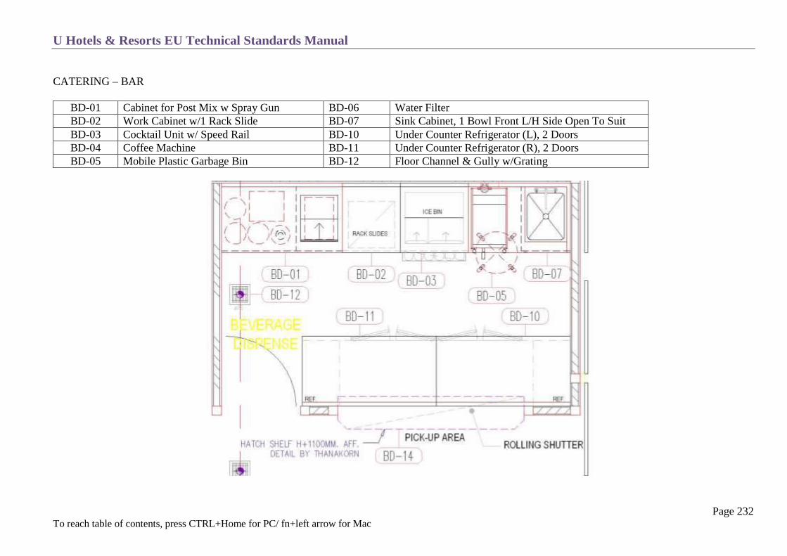
U Hotels & Resorts EU Technical Standards Manual
Page 232 To reach table of contents, press CTRL+Home for PC/ fn+left arrow for Mac
CATERING – BAR
BD-01 Cabinet for Post Mix w Spray Gun BD-06 Water Filter
BD-02 Work Cabinet w/1 Rack Slide BD-07 Sink Cabinet, 1 Bowl Front L/H Side Open To Suit
BD-03 Cocktail Unit w/ Speed Rail BD-10 Under Counter Refrigerator (L), 2 Doors
BD-04 Coffee Machine BD-11 Under Counter Refrigerator (R), 2 Doors
BD-05 Mobile Plastic Garbage Bin BD-12 Floor Channel & Gully w/Grating

U Hotels & Resorts EU Technical Standards Manual
Page 233 To reach table of contents, press CTRL+Home for PC/ fn+left arrow for Mac
SWIMMING POOL BAR / RESTAURANT
UPB-01 Work Cabinet w. Hinge Door UPB-13 Bar Blender
UPB-02 Work Cabinet UPB-14 Work Cabinet
UPB-03 Glass Washer UPB-15 Rack Slide Cabinet
UPB-04 Drop In Sink Cabinet w. Trash Drawer UPB-16 Cocktail Unit w. Ice Bin
UPB-05&6 U/C Refrigerator, 2 Glass Doors UPB-17 Drop In Sink Cabinet w. Trash Drawer
UPB-07 Water Boiler UPB-18 C/C Ice Machine
UPB-08 Coffee Machine UPB-19 Work Cabinet
UPB-09 Work Cabinet w. Hinge Door UPB-20 POS Station
UPB-11 Water Filter w. UV System UPB-21 Work Cabinet
UPB-12 Work Cabinet w Hinge Door UPB-22+23 Juice Extractor / Ice Crusher

U Hotels & Resorts EU Technical Standards Manual
Page 234 To reach table of contents, press CTRL+Home for PC/ fn+left arrow for Mac
SATELLITE KITCHENS EXAMPLE: SPECIALITY RESTAURANT
USK-01 Equipment Stand
USK-02 Convection Oven
USK-03 Exhaust Hood w. Fresh Air
USK-04 U/C Refrigerator, 2 Doors
USK-05 Work Cabinet
USK-06 Double Wall Shelf
USK-07 U/C Refrigerator, 2 Drawer
USK-08 6 Open Burner Gas Range w. Stand
USK-09 Gar Fryer
USK-10 Gas Griddle w/ Stand
USK-11 Electric Salamander w. Hanging Shelf
USK-12 Work Table
USK-13 Sink Cabinet, 1 Bowl & Trash Drawer
USK-14 Work Table
USK-15 Drop-In Induction Units
USK-16 Heat Lamps
USK-17 Drop-In Frost Top w. Remote Condensing
USK-18 Conveyor Toaster
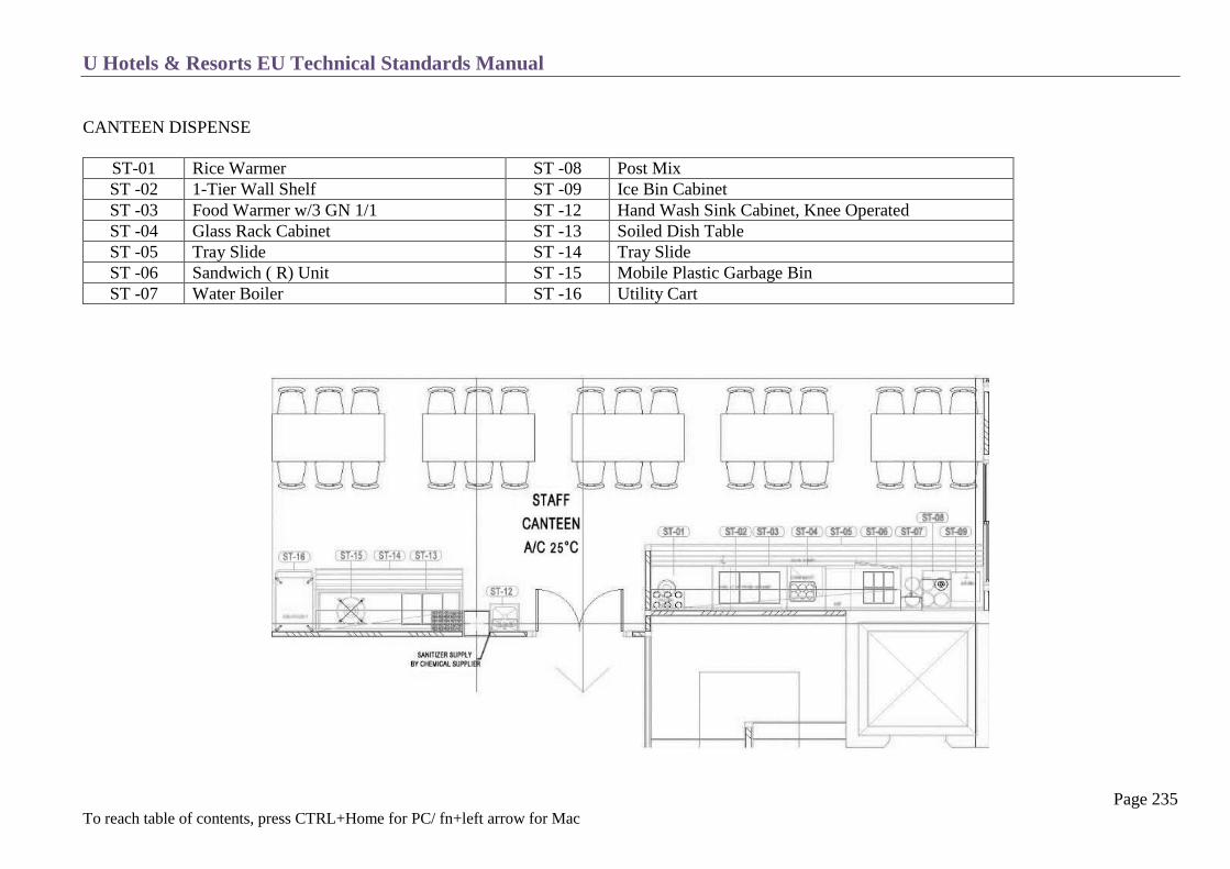
U Hotels & Resorts EU Technical Standards Manual
Page 235 To reach table of contents, press CTRL+Home for PC/ fn+left arrow for Mac
CANTEEN DISPENSE
ST-01 Rice Warmer ST -08 Post Mix
ST -02 1-Tier Wall Shelf ST -09 Ice Bin Cabinet
ST -03 Food Warmer w/3 GN 1/1 ST -12 Hand Wash Sink Cabinet, Knee Operated
ST -04 Glass Rack Cabinet ST -13 Soiled Dish Table
ST -05 Tray Slide ST -14 Tray Slide
ST -06 Sandwich ( R) Unit ST -15 Mobile Plastic Garbage Bin
ST -07 Water Boiler ST -16 Utility Cart

U Hotels & Resorts EU Technical Standards Manual
Page 236 To reach table of contents, press CTRL+Home for PC/ fn+left arrow for Mac
COLD ROOMS
General
Temperatures
Construction
Electrical Equipment
Refrigeration Equipment
Doors
Interior Equipment
U Hotels & Resorts EU Technical Standards Manual
Page 237 To reach table of contents, press CTRL+Home for PC/ fn+left arrow for Mac
GENERAL
They are of 2 types:
Main store
Daily store
Daily stores are located near cold and hot preparation areas in the main kitchen and also in the satellite kitchens and pantries.
These two types of cold rooms are complemented by refrigerated stores and drawers of different sizes, according to kitchen needs.
There must be a cold room for fruits and vegetables, one for meat/ fish / poultry and one for butter, eggs and cheeses.
There must be also at least one -20˚C deep-freeze room.
The size and number of cold rooms for a particular project will be defined by U Hotels & Resorts.
The bakery-pastry is equipped with a separate cold room and freezer.
U Hotels & Resorts EU Technical Standards Manual
Page 238 To reach table of contents, press CTRL+Home for PC/ fn+left arrow for Mac
TEMPERATURES
Maximum temperatures inside the cold storage rooms will be maintained at:
Meats 0 to + 4˚C
Fish 0 to + 2˚C
Dairy products 0 to + 6˚C
Vegetables 0 to + 8˚C
Frozen foods - 20˚C
Wine cellar + 14˚C
Daily cold rooms 0 to + 3˚C
Pastry 0 to + 3˚C
Frozen pastry - 20˚C
To achieve these temperatures, the following elements will have to be taken into account:
Ambient temperature
Quantity by weight of merchandise
Rate of deliveries
Defining these elements depends on the local climatic and supply conditions for each hotel.

U Hotels & Resorts EU Technical Standards Manual
Page 239 To reach table of contents, press CTRL+Home for PC/ fn+left arrow for Mac
CONSTRUCTION
Dimensions
Minimum internal height : 2,40 m and 2,10 under evaporator
Net door passageway dimensions: 1.90 × 0.90 m.
Area : as per brief, and allowing for trolley manoeuvring
Design
Cold rooms should preferably be built in place using traditional materials with possibly prefabricated panels and must follow precisely the
manufacturer specifications.
For masonry rooms, floors will be constituted of successive layers of: a watertight coating of asphalt with upsweep, insulation, a concrete slab and
20×20 cm non-slip stoneware tiles.
In both cases, the chamber will be carefully sealed from the ground to avoid all water infiltration.
Freezers will be equipped with an insulated ventilation system.
Floor slopes in the rooms will be a minimum of 1% towards the door.
Channelled stoneware baseboards are placed between floors and walls.
Walls will be covered with square-edged, light-coloured enamelled clay tiles or stainless steel.
Ceilings will have a cement rendering and painted with two coats of white paint approved by the health authorities.
All principal walls within the room will be protected by metallic angles to a height of 2 meters.
There should be no sill between the floor of the cold rooms and the surrounding areas.
From the start of construction, make allowances for depressed concrete slabs (about 18 cm for coolers, 23 cm for freezers).
Water Drainage
All water from washing and de-icing will be drained via floor traps located in the neutral chamber providing access to the cold room.
Drainage pipes within the freezers will be equipped with low-voltage heating elements.
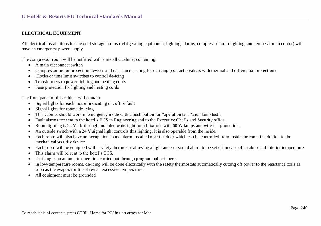
U Hotels & Resorts EU Technical Standards Manual
Page 240 To reach table of contents, press CTRL+Home for PC/ fn+left arrow for Mac
ELECTRICAL EQUIPMENT
All electrical installations for the cold storage rooms (refrigerating equipment, lighting, alarms, compressor room lighting, and temperature recorder) will
have an emergency power supply.
The compressor room will be outfitted with a metallic cabinet containing:
A main disconnect switch
Compressor motor protection devices and resistance heating for de-icing (contact breakers with thermal and differential protection)
Clocks or time limit switches to control de-icing
Transformers to power lighting and heating cords
Fuse protection for lighting and heating cords
The front panel of this cabinet will contain:
Signal lights for each motor, indicating on, off or fault
Signal lights for rooms de-icing
This cabinet should work in emergency mode with a push button for “operation test “and “lamp test”.
Fault alarms are sent to the hotel’s BCS in Engineering and to the Executive Chef’s and Security office.
Room lighting is 24 V. dc through moulded watertight round fixtures with 60 W lamps and wire-net protection.
An outside switch with a 24 V signal light controls this lighting. It is also operable from the inside.
Each room will also have an occupation sound alarm installed near the door which can be controlled from inside the room in addition to the
mechanical security device.
Each room will be equipped with a safety thermostat allowing a light and / or sound alarm to be set off in case of an abnormal interior temperature.
This alarm will be sent to the hotel’s BCS.
De-icing is an automatic operation carried out through programmable timers.
In low-temperature rooms, de-icing will be done electrically with the safety thermostats automatically cutting off power to the resistance coils as
soon as the evaporator fins show an excessive temperature.
All equipment must be grounded.

U Hotels & Resorts EU Technical Standards Manual
Page 241 To reach table of contents, press CTRL+Home for PC/ fn+left arrow for Mac
REFRIGERATION EQUIPMENT
Compressors for all the cold rooms will be grouped in a separated compressor area and specially ventilated with a screened façade.
Compressors will be semi-hermetic recycled water condenser units powered by electric motors. They will use a heat-recovery system and a specific
cooling tower. They will be equipped with HP pressure-sensitive safety switches.
There will be a single compressor for each room, installed on an anti-vibration stand.
Evaporators are ceiling units with flow control by thermostatic pressure reducing valves.
A door contact switch will cut off power to the evaporator fan (s) in case the door is opened.
Each room’s temperature will depend on an adjustable thermostat located close to the entrance door, controlling a solenoid valve on the refrigerant
piping.
Recording thermometers will be installed outside each room to indicate inside temperatures.

U Hotels & Resorts EU Technical Standards Manual
Page 242 To reach table of contents, press CTRL+Home for PC/ fn+left arrow for Mac
DOORS
The doors to the rooms will be armoured with 1-meter high stainless steel sheets. These will be hermetically-sealed doors with standard dimensions
of 190 × 90 cm.
They will be provided with a manual interior opening system for safety.
The installation of “air-seal” curtains at the entrance to rooms is recommended.
Calculations will take into account frequent door openings. In some cases, the possibility of a fast freezer compartment will be studied.
Locks will be key operated and integrated on the hotel key-chart (see chapter T-5 Locks).
INTERIOR EQUIPMENT
Cold rooms will be provided with stainless steel shelves and hooks rods.
This equipment must be removable and of easy maintenance.

U Hotels & Resorts EU Technical Standards Manual
Page 243 To reach table of contents, press CTRL+Home for PC/ fn+left arrow for Mac
SUPPLY AND WASTE
Supply and Waste Circuit
Supply Reception
Goods Storage
Waste Areas
Typical Layout

U Hotels & Resorts EU Technical Standards Manual
Page 244 To reach table of contents, press CTRL+Home for PC/ fn+left arrow for Mac
SUPPLY AND WASTE CIRCUIT
This schematic layout is to be adapted as per the Hotel Brief.

U Hotels & Resorts EU Technical Standards Manual
Page 245 To reach table of contents, press CTRL+Home for PC/ fn+left arrow for Mac
SUPPLY RECEPTION
Service Yard
Reserved for delivery trucks uploading on the loading dock and entry and exit manoeuvres.
This is an enclosed space with a door equipped with impact fenders; it will be tarred or cemented with a steep gully slope, waste traps and water
points.
It will be illuminated.
Any view from the rooms on this yard will be avoided (by roofing etc.); in all cases the minimum clear height will be 4.10 m.
Loading Dock
Separate from the garbage and employee platform.
It is at the height of the rear of the trucks, protected by a buffer, and with an angle-iron nosing.
It will have a gutter with grating at the foot of the platform; the whole of the platform can be key-locked (grill or gate) via passkey.
All the walls will be covered with tiles and equipped with metal angle plates at all exposed corners.
Floor will be tiled or epoxy painted.
It will include:
o a weighing machine (500 kg)
o a floor drain
o double sink
The staircase linking the platform to the yard will be equipped with step-nosing and skid-proof strips.
Goods Receiving Office
This is an entry and exit control office with distribution to the storage areas.
It will have a large window bay with counter giving onto the platform.

U Hotels & Resorts EU Technical Standards Manual
Page 246 To reach table of contents, press CTRL+Home for PC/ fn+left arrow for Mac
Purchasing Office
This is located close to the goods entrance and is accessible to visitors.
The goods receiving and purchasing offices have electrical and computer terminal connections as per all other offices.
In small hotels of less than 80 rooms they can be combined.
Sorting and Washing
These areas are only needed in special cases where regulations or the nature of deliveries require preparation before storage.
These areas will be defined in the Hotel Brief.
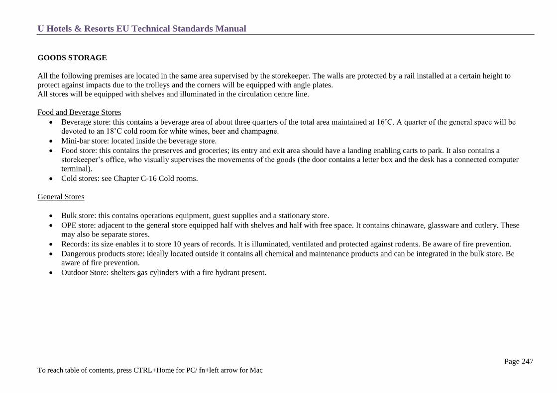
U Hotels & Resorts EU Technical Standards Manual
Page 247 To reach table of contents, press CTRL+Home for PC/ fn+left arrow for Mac
GOODS STORAGE
All the following premises are located in the same area supervised by the storekeeper. The walls are protected by a rail installed at a certain height to
protect against impacts due to the trolleys and the corners will be equipped with angle plates.
All stores will be equipped with shelves and illuminated in the circulation centre line.
Food and Beverage Stores
Beverage store: this contains a beverage area of about three quarters of the total area maintained at 16˚C. A quarter of the general space will be
devoted to an 18˚C cold room for white wines, beer and champagne.
Mini-bar store: located inside the beverage store.
Food store: this contains the preserves and groceries; its entry and exit area should have a landing enabling carts to park. It also contains a
storekeeper’s office, who visually supervises the movements of the goods (the door contains a letter box and the desk has a connected computer
terminal).
Cold stores: see Chapter C-16 Cold rooms.
General Stores
Bulk store: this contains operations equipment, guest supplies and a stationary store.
OPE store: adjacent to the general store equipped half with shelves and half with free space. It contains chinaware, glassware and cutlery. These
may also be separate stores.
Records: its size enables it to store 10 years of records. It is illuminated, ventilated and protected against rodents. Be aware of fire prevention.
Dangerous products store: ideally located outside it contains all chemical and maintenance products and can be integrated in the bulk store. Be
aware of fire prevention.
Outdoor Store: shelters gas cylinders with a fire hydrant present.
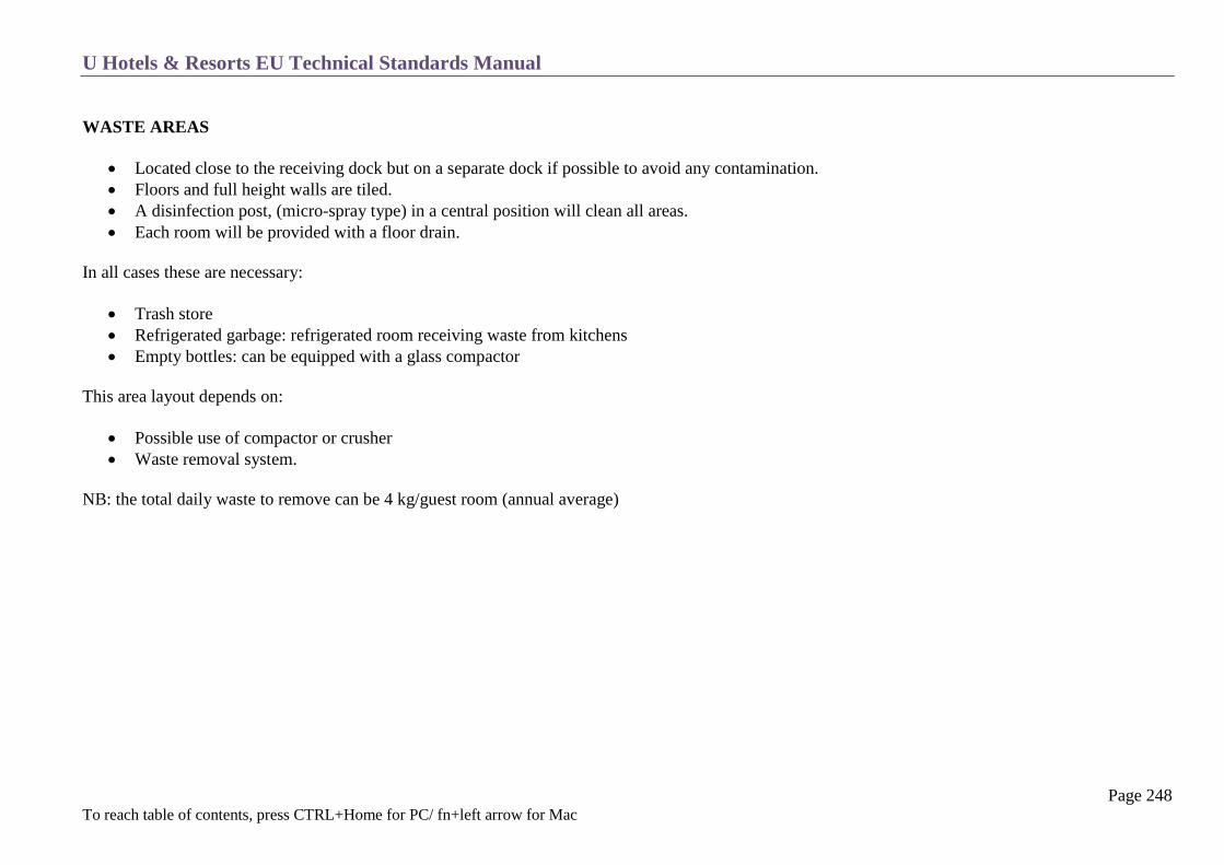
U Hotels & Resorts EU Technical Standards Manual
Page 248 To reach table of contents, press CTRL+Home for PC/ fn+left arrow for Mac
WASTE AREAS
Located close to the receiving dock but on a separate dock if possible to avoid any contamination.
Floors and full height walls are tiled.
A disinfection post, (micro-spray type) in a central position will clean all areas.
Each room will be provided with a floor drain.
In all cases these are necessary:
Trash store
Refrigerated garbage: refrigerated room receiving waste from kitchens
Empty bottles: can be equipped with a glass compactor
This area layout depends on:
Possible use of compactor or crusher
Waste removal system.
NB: the total daily waste to remove can be 4 kg/guest room (annual average)

U Hotels & Resorts EU Technical Standards Manual
Page 249 To reach table of contents, press CTRL+Home for PC/ fn+left arrow for Mac
TYPICAL LAYOUT
Typical layout of receiving area
A1 Scale
A2 Double Bowl Sink
A3 Spray Unit
A4 Waste Bin
A5 Meat & Vegetable
Trolley
A6 Working Bench
A7 Shelving Unit
A8 Cargo Carrying Trolley
A9 Shelving Units
A10 Working Bench
A11 Shelving Units
U Hotels & Resorts EU Technical Standards Manual
Page 250 To reach table of contents, press CTRL+Home for PC/ fn+left arrow for Mac
EMPLOYEES
Personnel Circuit
Time Keeper – Security
Human Resources Offices
Medical Services
Locker Rooms – Washrooms
Cafeteria
Miscellaneous
Service Corridors

U Hotels & Resorts EU Technical Standards Manual
Page 251 To reach table of contents, press CTRL+Home for PC/ fn+left arrow for Mac
PERSONNEL CIRCUIT
The personnel have a specific entry completely separate from the goods and garbage.

U Hotels & Resorts EU Technical Standards Manual
Page 252 To reach table of contents, press CTRL+Home for PC/ fn+left arrow for Mac
TIME KEEPER OFFICE – SECURITY
Located near the specific employee entrance in order to allow visual control of entrances and departures.
It can be combined with a security room when there is no specific security office (provide a counter in the service corridor and a notice board). The
room will be secured by a key.
It is equipped with a personnel time management system with a magnetic card reader outside the time keeper’s office and a terminal and printer in
the personnel office.
In smaller hotels these functions, although still identified by separate desks, can be combined with the receiving/purchasing areas in one volume as
long as visual control can be kept on both employees and goods entrances and movements.
HUMAN RESOURCES OFFICES
Includes a DHR office and a room with a secretary and reception area plus a training room on the personnel entrance circuit before or after the time
keeper.
The secretary’s area must control the access to the director’s office.
MEDICAL SERVICE (FOR HOTELS WITH 80+ ROOMS)
This is used by the employees but can be accessible to customers if required.
It includes (if fully equipped):
a medical treatment room
a consulting room

U Hotels & Resorts EU Technical Standards Manual
Page 253 To reach table of contents, press CTRL+Home for PC/ fn+left arrow for Mac
LOCKER ROOMS – WASHROOMS
The space scheduled in the brief takes into account:
The number of employees
The male/female proportion.
The number of temporary employees (“casuals”) for which additional locker rooms and washrooms must be provided (usually, about 5% of the total
with separate toilets).
In all cases the equipment will include:
For all areas:
waterproofing with floor drain and a minimum slope of 2%
tiling on the floors and walls
a clock
significant exhaust ventilation (approximately 5 vol/h)
watertight round-type luminous points, with metal protection, placed well above the passageway
locker approximate dimensions: 180 cm high, 60 cm deep, 35cm wide (single or double height).
benches
full-length mirrors
a shoe-shining point
fixed garbage cans
For the toilets:
washbasins with mirrors, shaver plugs, soap dispensers and hand dryers
showers with concealed pipes and changing booths with double coat hangers.
toilets with coat hanger.
floor drains will be provided to avoid any stagnant water.

U Hotels & Resorts EU Technical Standards Manual
Page 254 To reach table of contents, press CTRL+Home for PC/ fn+left arrow for Mac
As a rule one piece of equipment will be provided (WC + shower + washbasin) for every 30 people.
For service rooms far away from locker rooms, specific washrooms will be provided.
It is necessary to provide a few lockers for dirty work, with a locker for work clothes and a locker for civilian clothes (kitchen employees,
maintenance employees and gardeners).
CAFETERIA
Self-service type for all employees.
Care will be given to the decoration and lighting. It will be soundproofed.
Its equipment, apart from the tables and chairs, will include beverage distributors, sound system, TV’s and notice boards.
The personnel washrooms will be nearby.
Provide a storage room.
Finishes and equipment will be chosen in coordination with the main consultant.
In most cases, food preparation should be prepared in an adjacent main kitchen to reduce the need for a separate kitchen, as well as a dish
washing area. If this is not possible then a separate food preparation and dishwasher area should be provided for.
MISCELLANEOUS
Recreation Room
Will include a TV set, armchairs and low tables. A space will be provided for billiards, table tennis or other games.
Bicycle and Motorcycle Garage
At the service courtyard level: it is fenced off, covered and enclosed with a wire fence.
It is used for employee’s bicycles and motorcycles (if applicable).

U Hotels & Resorts EU Technical Standards Manual
Page 255 To reach table of contents, press CTRL+Home for PC/ fn+left arrow for Mac
SERVICE CORRIDORS
The service circulations will be designed in order to connect together the different rooms in the most functional and simplest possible way.
On all corridors used by trolleys (which means everywhere, except specific personnel circuits) protection rails, angle corners and 1.80 m
minimum width or more according to traffic will be provided.
Steps will be avoided; ramps will be 5 % slope (maximum 10% for extreme cases and short runs) and with anti-skid texture.
Door sizes will be standardized. For example, simple doors would be 100 cm and double doors could be 140 cm. If possible, doors should be
avoided across service passageways. They should always be protected by from carts by high kick plates, and fitted with oculus where necessary.
Service elevators and hoists will be always in close proximity to a service stair allowing direct connections in case of breakdown or maintenance
(specifically for service entrances, connections between kitchen and storage and housekeeping pantries).

U Hotels & Resorts EU Technical Standards Manual
Page 256 To reach table of contents, press CTRL+Home for PC/ fn+left arrow for Mac
TECHNICAL ROOMS
General
Boiler Room
Domestic Hot Water Production
Refrigeration Room
Air Handling Units
Water Boosters and Water Tank
Elevator Machinery
Transformer and Electrical Switch Gear Rooms
PABX and Battery Rooms
Generators Room
Workshops
Miscellaneous Rooms
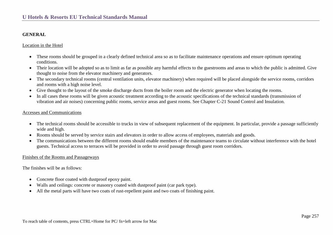
U Hotels & Resorts EU Technical Standards Manual
Page 257 To reach table of contents, press CTRL+Home for PC/ fn+left arrow for Mac
GENERAL
Location in the Hotel
These rooms should be grouped in a clearly defined technical area so as to facilitate maintenance operations and ensure optimum operating
conditions.
Their location will be adopted so as to limit as far as possible any harmful effects to the guestrooms and areas to which the public is admitted. Give
thought to noise from the elevator machinery and generators.
The secondary technical rooms (central ventilation units, elevator machinery) when required will be placed alongside the service rooms, corridors
and rooms with a high noise level.
Give thought to the layout of the smoke discharge ducts from the boiler room and the electric generator when locating the rooms.
In all cases these rooms will be given acoustic treatment according to the acoustic specifications of the technical standards (transmission of
vibration and air noises) concerning public rooms, service areas and guest rooms. See Chapter C-21 Sound Control and Insulation.
Accesses and Communications
The technical rooms should be accessible to trucks in view of subsequent replacement of the equipment. In particular, provide a passage sufficiently
wide and high.
Rooms should be served by service stairs and elevators in order to allow access of employees, materials and goods.
The communications between the different rooms should enable members of the maintenance teams to circulate without interference with the hotel
guests. Technical access to terraces will be provided in order to avoid passage through guest room corridors.
Finishes of the Rooms and Passageways
The finishes will be as follows:
Concrete floor coated with dustproof epoxy paint.
Walls and ceilings: concrete or masonry coated with dustproof paint (car park type).
All the metal parts will have two coats of rust-repellent paint and two coats of finishing paint.

U Hotels & Resorts EU Technical Standards Manual
Page 258 To reach table of contents, press CTRL+Home for PC/ fn+left arrow for Mac
Lighting
The levels of illumination are those defined in Chapter T-12 Electricity. The appliances are installed to illuminate the equipment, especially the
switchboards and measuring instruments.
Electrical Equipment and Low Voltage
Apart from the supply of the technical equipment, provide in all rooms:
o a panel containing one 2 × 10/16 AMPS grounded outlet and one 2 × 32 AMPS grounded outlet protected by differential residual circuit
breaker, sensitivity 30 mA
o emergency lighting via self-contained units secured over the exits
o lighting taken from the emergency power supply for certain priority premises (maintenance offices and workshops, control room, boiler
rooms, transformer, LVS, electric generator, elevator machinery)
o Wall-mounted telephone sets in the rooms and passageways.
The power cabinet will be separate from the lighting cabinet.
The workshops equipped with machine tools will have emergency punch switches, cutting off all the power distributed throughout the room.
Air Conditioning and Ventilation
Efficient ventilation of rooms will be provided.
Provide efficient ventilation of the premises and air conditioning if the heat releases or sensitivity of the equipment requires. In all cases, maintain a
temperature less than or equal to 28˚C, if necessary (for instance by recycling the air exhausted from the public premises).
The ventilation outlets should be at least 2.5 m away from any opening.
Miscellaneous Equipment
Doors with anti-panic opening will give access to staircase or emergency exits.
Floors drains in all rooms (except electrical rooms), and waterproofing on the floor if they are above another room.
All arrangements necessary to handle the equipment (provide a rail above all heavy equipment).
All the technical equipment will be installed on a stand with anti-vibration mounts.
Water taps will be provided in order to maintain and clean technical rooms.

U Hotels & Resorts EU Technical Standards Manual
Page 259 To reach table of contents, press CTRL+Home for PC/ fn+left arrow for Mac
Safety instructions, maintenance procedures and flow diagram panels will be posted next to the corresponding equipment.
BOILER ROOM
Access
This must be through a lobby with a mandatory second access door (for emergencies).
Layout of the Equipment
The boilers will be installed so that the clear space between the wall of the boiler room and the side of the nearest boiler is more than 1 m.
The minimum clear space between boilers should be 0.80.The minimum clear space in front (or the back) of the boilers should be 2.5 m so as to be
able to remove water tubes when necessary.
The clear spaces thus defined should have a minimum height of 2.00 m from the floor.
Fire Safety
Smoke detectors.
Safety breaker: this cuts off the gas, fuel oil and electricity supply from outside the room.
Boilers are installed on a 10 cm minimum height concrete pad.
Ventilation
Besides smoke breeching and stacks (or chimneys), the boiler room must have two permanent air supply openings and exhausts:
Exhausts: located in the ceiling to evacuate air with one or several ducts associated with the smoke ducts. Their total section is at least equal to the
half-section of the smoke ducts.
Air supply: at floor level in order to maintain atmospheric pressure inside the boiler room.
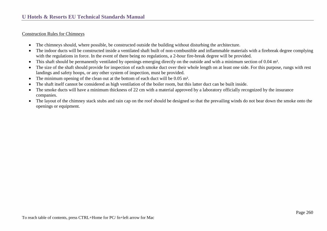
U Hotels & Resorts EU Technical Standards Manual
Page 260 To reach table of contents, press CTRL+Home for PC/ fn+left arrow for Mac
Construction Rules for Chimneys
The chimneys should, where possible, be constructed outside the building without disturbing the architecture.
The indoor ducts will be constructed inside a ventilated shaft built of non-combustible and inflammable materials with a firebreak degree complying
with the regulations in force. In the event of there being no regulations, a 2-hour fire-break degree will be provided.
This shaft should be permanently ventilated by openings emerging directly on the outside and with a minimum section of 0.04 m².
The size of the shaft should provide for inspection of each smoke duct over their whole length on at least one side. For this purpose, rungs with rest
landings and safety hoops, or any other system of inspection, must be provided.
The minimum opening of the clean out at the bottom of each duct will be 0.05 m².
The shaft itself cannot be considered as high ventilation of the boiler room, but this latter duct can be built inside.
The smoke ducts will have a minimum thickness of 22 cm with a material approved by a laboratory officially recognized by the insurance
companies.
The layout of the chimney stack stubs and rain cap on the roof should be designed so that the prevailing winds do not bear down the smoke onto the
openings or equipment.
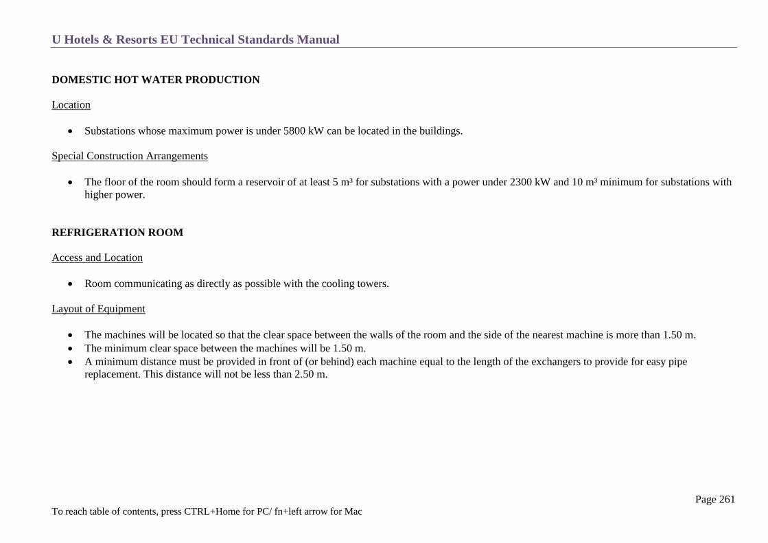
U Hotels & Resorts EU Technical Standards Manual
Page 261 To reach table of contents, press CTRL+Home for PC/ fn+left arrow for Mac
DOMESTIC HOT WATER PRODUCTION
Location
Substations whose maximum power is under 5800 kW can be located in the buildings.
Special Construction Arrangements
The floor of the room should form a reservoir of at least 5 m³ for substations with a power under 2300 kW and 10 m³ minimum for substations with
higher power.
REFRIGERATION ROOM
Access and Location
Room communicating as directly as possible with the cooling towers.
Layout of Equipment
The machines will be located so that the clear space between the walls of the room and the side of the nearest machine is more than 1.50 m.
The minimum clear space between the machines will be 1.50 m.
A minimum distance must be provided in front of (or behind) each machine equal to the length of the exchangers to provide for easy pipe
replacement. This distance will not be less than 2.50 m.
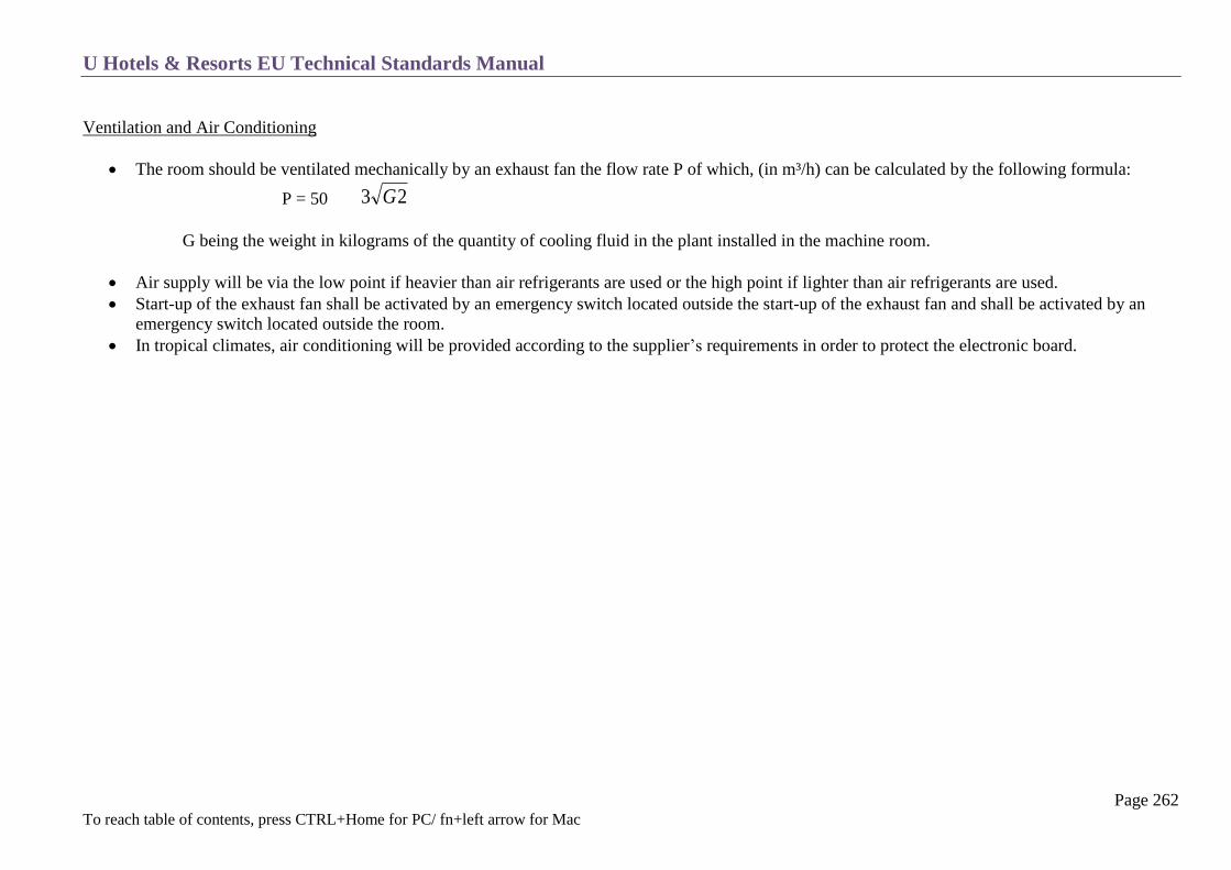
U Hotels & Resorts EU Technical Standards Manual
Page 262 To reach table of contents, press CTRL+Home for PC/ fn+left arrow for Mac
Ventilation and Air Conditioning
The room should be ventilated mechanically by an exhaust fan the flow rate P of which, (in m³/h) can be calculated by the following formula:
P = 50 23 G
G being the weight in kilograms of the quantity of cooling fluid in the plant installed in the machine room.
Air supply will be via the low point if heavier than air refrigerants are used or the high point if lighter than air refrigerants are used.
Start-up of the exhaust fan shall be activated by an emergency switch located outside the start-up of the exhaust fan and shall be activated by an
emergency switch located outside the room.
In tropical climates, air conditioning will be provided according to the supplier’s requirements in order to protect the electronic board.
U Hotels & Resorts EU Technical Standards Manual
Page 263 To reach table of contents, press CTRL+Home for PC/ fn+left arrow for Mac
AIR HANDLING UNITS
Rooms housing A.H.Us must be independent from the boiler room, refrigeration room and electrical rooms.
The layout of the equipment should provide for easy circulation and removal of filters and coils.
Floor drains required (and waterproofing if the room is not at ground level).
WATER BOOSTERS AND WATER TANKS
The technical room containing the main pipes, valves and boosting should be at least 1.00 m below the lower level of the water tanks so as to
provide for gravity flow of the water either towards the booster or towards the drain.
Slopes should be provided on the floor to drain off towards the drainage lifting station.
Spaces of at least 1 meter should be left between the large pipes and between the different pieces of equipment.
Water tanks will be equipped with access hatches and interior ladders for cleaning.
ELEVATOR MACHINERY
The ventilation should be efficient. The temperature in elevator machine room should be kept at 35 C or below.

U Hotels & Resorts EU Technical Standards Manual
Page 264 To reach table of contents, press CTRL+Home for PC/ fn+left arrow for Mac
TRANSFORMER AND ELECTRICAL SWITCH GEAR ROOMS
Layout of Equipment
Provide sufficient space allowing maximum accessibility and at least the following clearances:
o HV substation: behind 0.10 m (1 m if accessibility behind is required); in front 1.20 m.
o LV switchboard: behind 0.80 m with passage from front to back; in front 1.20 m.
o Transformers: if they are installed against a partition wall, provide 20 cm between the partition and the transformers; 1.50 m to let through
the transformers; 0.60 m between transformers and 0.20 m behind.
Floor reservoir will be provided for liquid insulator transformers.
Avoid all water influxes and provide a threshold at the entrance; if the room is in the basement provide a tanking.
The transformer room will generally open directly onto the outside and will be located so as to be as near as possible to the centre of gravity of the
powers to be serviced.
Follow the specifications of the local power supplier.
Passage of Cables
The cables should be laid in troughs covered with metal plates.
The layout and dimensions of the troughs should enable the cables bending radius to be respected, and the cables to be placed in a single layer with
30% reserve space.
Ventilation
The ventilation will preferably be natural for the rooms.
In the event of this natural ventilation being impossible owing to the layout of the rooms, or if the temperature of the site is higher than 30˚C, then
mechanical ventilation must be provided.
This ventilation will be controlled by thermostat which will trigger the speed of the fan.
A spare fan will be provided for all the rooms ventilated mechanically with a selector switch and automatic starting on an operating failure of a fan
in service.

U Hotels & Resorts EU Technical Standards Manual
Page 265 To reach table of contents, press CTRL+Home for PC/ fn+left arrow for Mac
Miscellaneous Arrangements
Provide all the necessary safety and working equipment (pole, gloves, mats, stools).
Provide the labelling of the cables.
Avoid water pipes in rooms above electrical stations.
Provide waterproofing on the floor if there is a risk of leakage.
Provide a 15 cm threshold with the outside.
PABX AND BATTERY ROOMS
The premises must remain absolutely clean: general dustproof paint and acid-proof tiling is required on the floor.
Sufficiently well sized to provide 1.00 m circulation between cabinets and between batteries.
Ventilation according to constructor’s instructions and provide air conditioning of the room.
GENERATOR ROOM
Will be located close to the main electrical switchgear with easy access for the equipment.
The minimum circulation around the generator should be 1.50 m.
Provide soundproofing for the room or the generator engine and vibration isolators.
Provide engine-cooling system.
Provide adequate ventilation for engine and generator radiated heat.
Locate the batteries on a raised stand.
The room will be equipped with a day fuel tank and transparent tube level gauge.
Smoke exhaust with a silencer will be located in order to create minimum pollution and sound nuisance, away from air intakes and windows.
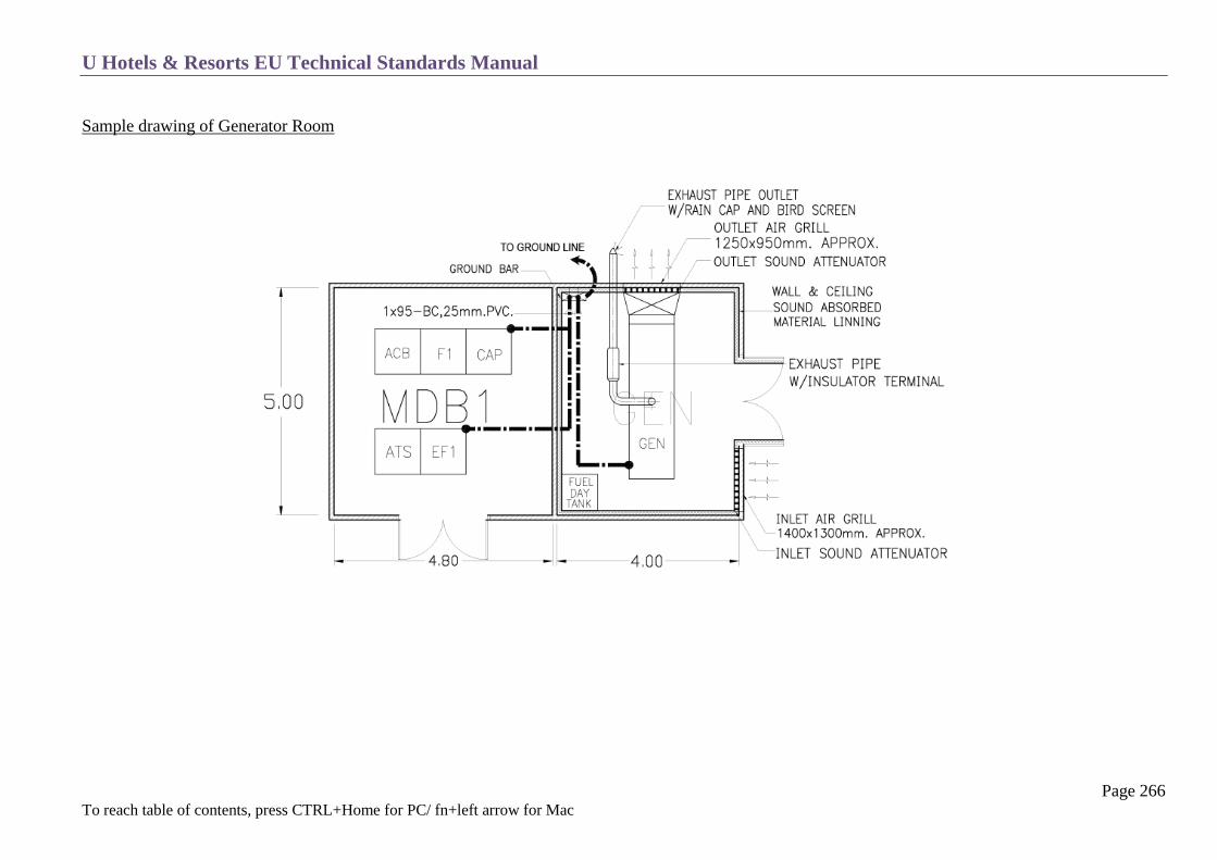
U Hotels & Resorts EU Technical Standards Manual
Page 266 To reach table of contents, press CTRL+Home for PC/ fn+left arrow for Mac
Sample drawing of Generator Room

U Hotels & Resorts EU Technical Standards Manual
Page 267 To reach table of contents, press CTRL+Home for PC/ fn+left arrow for Mac
WORKSHOPS
Electricity: provide wall mounted electrical panels with low voltage outlets, TV outlet, RJ45 outlet,
Paint shop: mechanical exhaust with filter.
MISCELLANEOUS ROOMS
Technical Control Room:
This room will contain, among other items, the main mimic panels and central computer of the hotel systems control (BCS), technical alarms
signals, remote controls, the central sound and T.V. racks, sprinkler alarms, technical system regulation control and a paging station. It can include a
desk for a technical department assistant. It is located close to the Engineer’s office and/or close to the main plant room.
This room, as well as the main I.T. room (if any), shall have a smoke and heat detection system.
Engineer’s office and assistant.
Drawings and files room with a drawing table.
Technical stores.
These are under the responsibility of the engineer: Storage of spare parts required for current maintenance (bulbs, thermostats, spare tools,
measuring instruments, etc.).
Maintenance lockers and washroom.
To be provided only in the event of the technical areas being remote from the personnel’s premises.
Technical shafts and galleries.
The voids in the dropped ceilings and large technical shafts must be equipped with lighting and socket outlets.
Sewage treatment plant.
Swimming pool treatment room (see chapter T-8 Sanitary Plumbing)
Lifting station
Kitchen grease separator (see chapter C 15 Kitchens)
Cold rooms compressors see chapter (C 16 Cold Rooms)

U Hotels & Resorts EU Technical Standards Manual
Page 268 To reach table of contents, press CTRL+Home for PC/ fn+left arrow for Mac
FIRE SAFETY
General
Building Organisation
Covering Materials
Emergency Lighting
Miscellaneous

U Hotels & Resorts EU Technical Standards Manual
Page 269 To reach table of contents, press CTRL+Home for PC/ fn+left arrow for Mac
These specifications are given as information only and are not limiting.
GENERAL
The U Hotels & Resorts standards do not require full sprinklers in all cases. See Chapter T-9 Fire Protection. Furthermore, the fire code of the country in
which the building is located must be observed as a priority. The rules that provided below are an example of building organisation and equipment
considered as a minimum requirement.
U Hotels & Resorts EU Technical Standards Manual
Page 270 To reach table of contents, press CTRL+Home for PC/ fn+left arrow for Mac
BUILDING ORGANISATION
Access to Buildings
The building should open, directly or indirectly, on one or several public roads with a minimum width of 8 meters to provide access for fire engines
and enable them to manoeuvre.
One façade at least should be accessible to fire trucks though a ladder access allowing installation of fire ladders. (See attached sketches).
Open spaces can replace ladder access as long as they allow installation of fire ladders in different spots in order to reach a window in each fire
sector of the building.
Isolation towards Adjacent Buildings
A hotel must be isolated from any adjacent building in order to avoid a fire spreading.
Means of Egress
Number and dimensions according to the number of people in the building.
On each floor, these numbers should take the upper floors into account.

U Hotels & Resorts EU Technical Standards Manual
Page 271 To reach table of contents, press CTRL+Home for PC/ fn+left arrow for Mac
BUILDING ORGANISATION
Capacity Number of
staircases Total minimum width of stairs
1 to 19 people
20 to 50 people
51 to 100 people
101 to 200 people
1
2
2
2
0.90 m (“1 unit” width)
0.90 m + accessory passage with minimum width 0.60
m
0.90 m + 0.90 m or 1.40 + 0.60
0.90 m + 1.40 m
Stairs
The corridors and enclosed or open-air staircases giving onto the exits should be distributed so as to avoid dead-end corridors of more than 10 m
and so that the distance from a room door to the closest stair is no more than 35 m (20 m in high-rise buildings). They should open directly outside
at the ground floor or less than 20 m from a protected exit way.
Open interior stairs are limited to one, connecting the two lower floors, in specific cases such as between the lobby and the first floor. They require
a specific study to follow the applicable codes, especially in terms or smoke removal.
Passages and Exits
Each passage should have a width in proportion to the number of people liable to use it, i.e. generally 0.60 m per fraction of 100 people or “unit” ,
given that no passage will be less than 1.40 m wide (i.e. two “units”). (Except for the supplementary and accessory passages). All the widths are
designed after deducting possible projections (pilasters, display cases, flap-seats, lockers etc.) excluding projections less than or equal to 10 cm
(handrails).
Long floor corridors should be subdivided at least every 30 m by sets of 90 minute flameproof walls and doors.

U Hotels & Resorts EU Technical Standards Manual
Page 272 To reach table of contents, press CTRL+Home for PC/ fn+left arrow for Mac
Exit Doors
These should have the following standardized dimension, ± 5%
single-leaf door 0.90 m minimum (one “unit”)
two equal leaf doors 1.40 m minimum (two “unit”)
two unequal leaf doors 1.80 m minimum, (3 “unit”) the largest should not be more than 1.10 m wide
Except for guestroom doors or doors leading to rooms occupied by less than 50 people they should open in the direction of the exit. Revolving doors can
only be accepted as an addition to the necessary passages. The opening of doors must not interfere with exit corridors.
Doors opening onto fire stairs must be self-closing and rated 2-hour fire resistant or 90 minute flame resistant.

U Hotels & Resorts EU Technical Standards Manual
Page 273 To reach table of contents, press CTRL+Home for PC/ fn+left arrow for Mac

U Hotels & Resorts EU Technical Standards Manual
Page 274 To reach table of contents, press CTRL+Home for PC/ fn+left arrow for Mac
Fire Resistance Rating
Exterior wall fire rating:
o Fire resistant wall: with all adjacent buildings, this should consist of a 2-hour fire-resistant wall, being increased to 3 hours if the adjacent
building contains special fire hazards.
o Isolation versus the building opposite: when the building opposite is less than 8 m from the façade, one of the facades should be 1 hour fire-
resistant.
o Floors: The isolation should be 2-hour fire-resistant. This degree will be increased to 3 hours if the adjacent building presents a fire hazard.
Fire rating between floors:
o Facades must not be built out of easily combustible materials and must be studied in order to limit the spread of fire from one level to the
other.
o Unless the building is fully sprinkler equipped, and the facades are made of fire-rated materials, the rule C + D> 1.30 m concerning fire
spreading obstacles from one floor to another must be applied (C = vertical distance from window top to window bottom, D = horizontal
distance from glass plane to floor edge).
o For hotels containing less than 1,500 people the floors should be 1 hour fire resistant.
Fire rating degree between kitchen, technical rooms and public areas:
o The kitchens, linen stores and laundries should not control the exits at the disposal of the public. These areas should be isolated from the
public areas by 1-hour fire-resistant walls, floors and partitions.
o The communicating bays or doors should be 90 minute fire-resistant.
Fire rating degree between high-risk areas and public areas:
o The maintenance and repair workshop, dangerous chemicals store and parking areas must be isolated from public areas by 2 hour fire-
resistant walls, floors and partitions.
o The communication bays or doors should be one hour fire-resistant.

U Hotels & Resorts EU Technical Standards Manual
Page 275 To reach table of contents, press CTRL+Home for PC/ fn+left arrow for Mac
Staircase shafts:
o These should be partitioned off by 90 minute fire-resistant walls, covered with incombustible materials. The doors should be 30 minute
flame-resistant.
Fire dampers:
o All the ducts crossing fire-resistant walls or floors must be provided with fire dampers at the crossing point.
Cases of high-rise buildings:
o The staircases should be partitioned off with 2-hour fire-resistant walls, including the vertical conduits.
o The doors and hatches should be 1-hour fire-resistant.
o The corridor enclosures should be 1-hour fire-resistant.
Fire stability of structures:
o The structures should be stable in fire for 90 minutes. This requires sufficient covering of the concrete reinforcement rods and rules out any
unprotected metal structure.
o In the case of a high-rise building, the structural elements of the building should be rated 2-hour fire-resistant.

U Hotels & Resorts EU Technical Standards Manual
Page 276 To reach table of contents, press CTRL+Home for PC/ fn+left arrow for Mac
COVERING MATERIALS
Except in guestrooms in low-rise buildings, the following should be in non-combustible materials (rated MO) or at least permanently non-
inflammable (M1):
o the hooking systems (rods, rings etc)
o the hangings and floating covering materials
o dropped ceilings and ceiling coverings (with MO suspension system)
o floating cross-curtains.
The following should be in materials permanently difficult to ignite (M2):
o non-floating covering materials
o translucent dropped ceilings.
o the relief decorative elements
The following should not be in easily inflammable materials (or better than M4):
o the space between materials and walls
o the floor coverings
Cases of high-rise buildings:
o the dropped ceilings should be rated 15 minute fire-stable in the public corridors
o all the covering materials should be at least difficult to ignite (M2)
o passages and the kitchens should be non-combustible(MO)
o the covering supports should always be non-combustible (MO).

U Hotels & Resorts EU Technical Standards Manual
Page 277 To reach table of contents, press CTRL+Home for PC/ fn+left arrow for Mac
EMERGENCY LIGHTING
The emergency lighting consists of:
o illuminated exit signage clearly indicating the direction of egress enabling everybody to get access to the outside plus identifying obstacles
and changes in direction
o the mandatory ambient lighting when the numbers of the public may be 100 per level and 50 in the basement. The light sources should not
be more than 15 m apart.
The emergency lighting can be of two types:
o central source with batteries or generators
o via self-contained units with a battery and charger for each unit.
See Chapter T 12 Electricity (subchapter emergency lighting).
Cases of high-rise buildings:
o all the materials making up this installation should be incombustible
o the emergency generator must supply the emergency installations before any other load.
o emergency installations have completely separate and duplicate protected electrical circuits.

U Hotels & Resorts EU Technical Standards Manual
Page 278 To reach table of contents, press CTRL+Home for PC/ fn+left arrow for Mac
SMOKE EXHAUST
Objectives
Smoke exhausts have three objectives:
In an initial stage; to enable the occupants of the compartment where the fire has broken out evacuate rapidly and get to a protected space as soon as
possible, without being hindered by smoke and without this smoke spreading out of the compartment.
In a second phase; to enable the rescue teams to rapidly locate the fire’s source and extinguish it without being impeded by the capacity of the
smoke.
To prevent smoke entering the staircases and adjacent compartments.
Natural Smoke Venting
Staircase:
In the upper part, the stairwell shaft should contain vents (skylights, exterior wall windows) with releasing devices enabling them to be opened from
the ground floor and the top landing floor while simultaneously opening the fresh-air supply.
Horizontal corridors:
o Very long corridors should be intersected every 25 to 30 m maximum by 90 minute flame-proof doors.
o Each compartment thus formed should be equipped with a smoke-exhaust device.
o The vents should have a ratio of 1/50 of the surface of the corridor or compartment.
o The distance between an air supply and a smoke exhaust should not exceed 10 m in a straight corridor and 7 m if there are changes in
direction.
Rooms to which the public is admitted:
o All the rooms to which the public has access should contain, in their upper part, one or several horizontal or vertical vents communicating
with the outside (ratio: 1/100 of the surface).
o If these vents are normally closed, it should be possible to open them by releasing stations easily accessible from the floor of the room and
located close to the main entrances. This station will be duplicated by an automatic releasing device connected to a smoke detector placed
close to an air return outlet.

U Hotels & Resorts EU Technical Standards Manual
Page 279 To reach table of contents, press CTRL+Home for PC/ fn+left arrow for Mac
Mechanical Smoke Removal
When natural smoke exhaust is not possible, then mechanical systems will be used. In case of fire, enclosed fire stairs will be supplied with fresh air and
kept at a pressure higher than that of adjacent areas.
Rooms under 300 sqm.
All the mechanical systems providing a minimum exhaust flow of 1 cu.m/s per 100 sqm can be used on condition that:
The lower part of the exhaust grille is located in the upper third of the room and at a minimum distance of 1.80 m from the floor.
The ducts are in non-combustible, non-flammable material, 1-hour fire-rated.
The exhaust fans can fulfil their function for a minimum time of 2 hours with smoke at 400˚C.
The ducts emerge at more than 8 m from an obstacle higher than them.
Smoke exhaust will be controlled by an automatic releasing device via detectors sensitive to smoke and combustion gases.
The automatic release will be duplicated by a manual station.
Room more than 300 sqm.
Creation of sections (which need not be materialised), of 300 sqm maximum.
Per section, provide at least one exhaust outlet normally closed by a 2-hour rated damper the opening of which is linked to the smoke detector.
The total exhaust flow per section should be at least 3 cu.m/s.
Exhaust will be obtained by fans. These can be grouped and used to exhaust several sections
NB.
In the event of several rooms being served by a mechanical smoke-exhaust system, the flow rate of the fan should be able to provide the total flow
rate corresponding to smoke exhaust of the two largest rooms.
Fresh-air supplies: in all cases, natural fresh air supplies will be provided allowing the sweeping of the rooms. The fresh air supply flow rates will
be 40% less than that of the air exhausted.
The fresh air supply grilles will be blanked off by fire dampers in the case of several grilles being placed on the same circuit. These dampers will be
controlled by the detectors.

U Hotels & Resorts EU Technical Standards Manual
Page 280 To reach table of contents, press CTRL+Home for PC/ fn+left arrow for Mac
In the event of the rooms being wide open on the outside, the openings can be considered as suppliers of fresh air.
Corridors
Mechanical smoke exhausts should be designed on the basis of 0.5 cu.m./s per fraction of 100 people.
The distance between an air supply and an exhaust outlet should not exceed 20 m in the case of a straight corridor and 14 m in the case of a non-
straight corridor.
The fire detection automatically activates the smoke-removal systems (fans and dampers).
Cases of high-rise buildings:
The communications between one compartment and another and with the stairwells should be equipped with smoke-proof vestibules at least 3 m³
each. The vestibule enclosures will be built to constitute a 2-hour fire-rated separation.
The stairwells should be kept constantly free of smoke.
The vestibules should be kept free of smoke in normal times and equipped so as to eliminate fumes rapidly when being used in case of fire in the
adjacent compartments.
Smoke should be permanently exhausted from the corridors in case of fire in the compartment.
According to the applicable code, different organizations could be adopted.
The stairs blowers shall ensure a minimum air speed of 0.5 m/s when the door is opened with an adjacent lobby.
This flow, added to the lobby air blower flow, shall ensure a minimum air speed of 1 m/s when the door is opened with an adjacent corridor.
The corridor extraction flow shall be at least 1.3 times the amount of the air supplied to it.

U Hotels & Resorts EU Technical Standards Manual
Page 281 To reach table of contents, press CTRL+Home for PC/ fn+left arrow for Mac
SMOKE REMOVAL
EXAMPLE A:
Blowers in stair, vestibules and corridors
Extraction in vestibules and corridors

U Hotels & Resorts EU Technical Standards Manual
Page 282 To reach table of contents, press CTRL+Home for PC/ fn+left arrow for Mac
SMOKE REMOVAL
EXAMPLE B:
Blower in stair and vestibules
transfer from lobbies
extraction from corridors
Stair to vestibule door (CF 1 hour)
Vestibule blower flap (PF 1 hour closed in waiting position, opened by fire
detection)
Vestibule to corridor door (CF ½ hour PF 1 hour)
Transfer flap (PF 1 hour, opened in waiting, position, closed if T > 70˚c)
Corridor extraction fire dampers (CF 2 hours, opened by fire detection,
spacing less than10 m
Extraction fan rated for 450˚c for 2 hours
Vestibule blower fan
Vestibule blower duct (CF 2 hour)
Corridor extraction duct (CF 2 hour)
CF = Fire resistant
PF = Plan resistant

U Hotels & Resorts EU Technical Standards Manual
Page 283 To reach table of contents, press CTRL+Home for PC/ fn+left arrow for Mac
MISCELLENOUS
Boiler Room
See Chapter C19 Technical Rooms
Gas Installation
See Chapter T8 Sanitary Plumbing – subchapter 6: gas
Air Treatment and Ventilation
See Chapter T 11 Ventilation – Air conditioning
Electrical Installation
See Chapter T 12 Electricity
Elevators and Escalators
See Chapter T 15 Elevators (lifts)
Kitchen
See Chapter C 15 Kitchens
Fire Fighting Means
See Chapter T 9 Fire Protection and T 10 Fire Detection

U Hotels & Resorts EU Technical Standards Manual
Page 284 To reach table of contents, press CTRL+Home for PC/ fn+left arrow for Mac
SOUND CONTROL & INSULATION
General
Grade Vibrations
Outdoor Airborne Sound
Indoor Airborne Sound
Impact Noises
Noise from Collective Equipment
Noises from Individual Equipment
Outside Equipment noises

U Hotels & Resorts EU Technical Standards Manual
Page 285 To reach table of contents, press CTRL+Home for PC/ fn+left arrow for Mac
GENERAL
Adequate sound control is one of the fastest-growing requirements in today’s hotel buildings.
Maximum Sound Levels
The current chapter deals with measures to be taken. These measures must achieve the following objectives (values are calculated according to EN/ISO
717-1):
Maximum general Sound level resulting
sound level from collective equipment
dB (LnAT)¹ noises dB (LnAT)
Guest rooms 32 30
Lobby 40 35
Restaurant 40 38
Meeting rooms, lounges 32 30
Offices 35 33
Kitchen, laundry 48 45
Sound insulation at different parts of the building will be designed to allow the following minimum value of insulation:
Noise given by Noise perceived by
Sound reduction in dB
(DnTA or RA or NR)²
Corridors Guest rooms (bed area)
40 (door itself: 37)
Guest rooms (or bathrooms) Guest rooms (or bathrooms)
53
Restrooms Guest rooms or public rooms
59
Meeting rooms Guest rooms or public rooms
59

U Hotels & Resorts EU Technical Standards Manual
Page 286 To reach table of contents, press CTRL+Home for PC/ fn+left arrow for Mac
Importance of a good acoustical design, sound insulation and reverberation control
Whatever the detailed measures, acoustical comfort will not be achieved if basic measures are not taken during the building design. It is much cheaper to
avoid noise problems in the initial design period than to correct them later.
GRADE VIBRATIONS
In case of projects built near an expressway, measures will be taken to avoid vibration transmission able to bring acoustical nuisance.
An anti-vibration break must be provided between the foundations and the building-bearing structure.
Therefore the bearing surface must rest on the foundations through vibration isolators.
In case of a building where only a part of the building needs to be insulated from grade vibrations, it is then necessary to provide a vertical
expansion joint at full height, between the insulated part and the non-insulated part.
OUTDOOR AIRBORNE SOUND
According to the level of the outdoor sound, the sound reduction of the façade should be adapted so as to obtain a sound level in the bedroom not exceeding
32 dB (LnAT). In all cases, the sound reduction of the façade should be 30 dB (DnTA or RA) at least.
Care must be taken over the following points:
Have a sufficient weight per square meter for the solid sections of the façade
Have sufficiently thick glass and frame without sound leaks. Glass façade is recommended to be of equal or higher than laminated ¼” +0.06 mm.
PVB+1/4” (STC-39, OITC-34)
In the case of double glazing, provide different thicknesses of the two panes with a large air gap in-between and absorbing material on the sides.
Avoid sound leaks in the façade (ventilation inlets, rolling shutters, boxes, roof structure etc.)
If necessary, install double windows.

U Hotels & Resorts EU Technical Standards Manual
Page 287 To reach table of contents, press CTRL+Home for PC/ fn+left arrow for Mac
Light weight block (G4) wall with cavity Light weight block (G4) wall without cavity
Overall thickness: minimum 200 mm. Overall thickness: minimum 250 mm.

U Hotels & Resorts EU Technical Standards Manual
Page 288 To reach table of contents, press CTRL+Home for PC/ fn+left arrow for Mac
To analyse the noise from to the street it will be necessary to:
Either make measurements according to the following criteria: the equivalent noise level will be measured taking the adequate time constants into
account (refer to NF S 31010 standard or approved equivalent) – the method used is to average the energy received from 8:00 AM to 8:00 PM. (For
comparison, the level between 8:00 PM and 8:00 AM shall also be computed).
The measurements will be made 2 meters in front of the future façade of the building

U Hotels & Resorts EU Technical Standards Manual
Page 289 To reach table of contents, press CTRL+Home for PC/ fn+left arrow for Mac
INDOOR AIRBORNE SOUND
In the layout, make sure to keep apart from noise-producing areas (technical rooms, nightclub, gym, and noisy animate areas) the rooms which
require a low sound level (bedrooms, conference rooms).
Insulation between bedrooms¹ : this should be at least 53 dB (DnTA) in situ and can be obtained by:
o 15 cm of concrete, or
o Special partitions and lining system which have been tested and achieved a high sound rating.
Insulation between bedroom and corridor: this should be at least 40 dB (DnTA) and can be obtained by :
o 15 cm of concrete, or
o 15 cm of solid bricks or concrete blocks coated on both sides, or
o Special partitions and lining system which have been tested and achieved a high sound rating.
o Dry walls with uneven side thickness, acoustical fillings, and special acoustical precautions (at the floor, ceiling and posts).
To achieve these figures it is imperative to take special care of the quality of the entrance door and connecting doors which determine most of the
acoustic attenuation of the partitions, and should have a rating of 37 dB (DnTA) minimum.
Entrance Doors
hardwood frame
thickness 40 mm with solid core
double rebate on the door edges and its frame
peripheral acoustic gasket
telescopic acoustic skirting
closer concealed in frame head
Connecting Doors (for each)
hardwood frame
thickness 40 mm with solid core
solid wood threshold with rebates involving the 2 doors
double rebate on the door edges and the frames
peripheral acoustic gasket

U Hotels & Resorts EU Technical Standards Manual
Page 290 To reach table of contents, press CTRL+Home for PC/ fn+left arrow for Mac
SAMPLE DOOR DETAIL
Bottom seal

U Hotels & Resorts EU Technical Standards Manual
Page 291 To reach table of contents, press CTRL+Home for PC/ fn+left arrow for Mac
The following points should also be carefully checked:
The fresh air inlet: provide a sound trap ensuring the necessary attenuation. Pipes from above bathrooms in false ceilings should be avoided or
sound treated.
Any PVC waste water pipe above the ceiling must be wrapped with sound insulation. Pipe lag or sound barrier foams is recommended for best
performance. However minimum performance of 2” stone wool is accepted. Those products are available by Wilhams, Armacell or Rockwool.
The switches, socket outlets and bathroom air exhausts must not be installed opposite each other on the same wall.
IMPACT NOISES
In all bathrooms and in the case of hard floor coverings (marble or tiling), provide a soundproofed floating topping.
Provide a floor covering producing good insulation against impact noises (fitted carpet with foam underfelt).
For the floating toppings, ensure that the work is done correctly and in particular that the screws fastening the sanitary appliances do not cross them.
U Hotels & Resorts EU Technical Standards Manual
Page 292 To reach table of contents, press CTRL+Home for PC/ fn+left arrow for Mac
NOISES FROM COLLECTIVE EQUIPMENT
The noise level generated in guestrooms by such equipment (elevators, exhaust fans, etc.) should not exceed 30 dB (LnAT).
Layout Precautions
The first precaution is a correct layout of the public premises and rooms versus the collective equipment.
Avoid a room being adjacent to an elevator shaft.
Do not superpose a room and:
o kitchen
o elevator machinery
o any technical rooms (exhaust fan or air coolers, for example).
Elevators
In the event of one side of the shaft being in contact with the rooms the wall must be lined with an air void between the two sides on all the contact faces.
The machinery will be placed above the shafts and not in contact with premises to which the public is admitted. The machines will be installed with anti-
vibration pads.
Technical Rooms
The mechanical equipment rooms shall be located far away from sensitive room
Use non sensitive buffer zones between and size equipment rooms to have sufficient space for operation, inspection and maintenance of all
equipment.
Fans, chillers and the like should not be located close to walls where sound can build up in the narrow space

U Hotels & Resorts EU Technical Standards Manual
Page 293 To reach table of contents, press CTRL+Home for PC/ fn+left arrow for Mac
Provide:
Anti-vibration sleeves on all the couplings, piping, rotating machines
Flexible sleeves on all the fan/duct couplings
Masonry stand laid on anti-vibration springs for all rotating machines including the boilers
Fairing on the burners and the emergency generators
Avoid rotation speeds above 1450 rpm for the pumps and burners
Wall balanced washing/drying machines, with automatic compensation and anti-vibration bases.
Sound attenuators on the outlet of the smoke ducts so as to obtain 42 dB(LnAT) on the façade nearest the outlet
Sound attenuators on all the exhaust ventilators to obtain 42 dB (LnAT) on the façade closest to the outlet
Sound attenuators on the outlets and return of the air-handling units
All the pipes and ducts held by anti-vibration supports, for complete insulation with respect to the structure.

U Hotels & Resorts EU Technical Standards Manual
Page 294 To reach table of contents, press CTRL+Home for PC/ fn+left arrow for Mac
Special case of the generator
As this is particularly noisy, special precautions must be taken:
Construction:
Floor:
As a general rule, see that the generator room is on a backfill.
Ceiling:
Provide a solid slab weight higher than 500 kg/sqm, doubled with a dropped ceiling in rigid and fixed sheets placed at least 10 cm below the
underside of the slab.
Wall in Elevation:
Provide two solid masonry walls (identical material separated by an air void of 3 cm minimum of different thicknesses whose total weight should be
greater than 450 kg/sqm). The walls in elevation will not be integrated with the slab. Example: two concrete walls respectively 15 cm and 10 cm
thick
Doors:
Double soundproof doors with a lobby in-between.
Generator Equipment:
Generator placed on min. 25 cm thick slab with anti-vibration springs in-between
Sound attenuators on the ventilation outlets in the room
Sound attenuators on the gas exhaust.

U Hotels & Resorts EU Technical Standards Manual
Page 295 To reach table of contents, press CTRL+Home for PC/ fn+left arrow for Mac
Piping
Water speed: the water speed in the risers will be limited to 1.2 m/s and 1.5 m/s in the main basement or crawl space distributions.
Supply pressure: maximum pressure 3 bars.
Pipe attachment: all the clamps or yokes attaching the pipes should be provided with rings or resilient devices.
Slab or wall crossings: the pipes should be enclosed with an insulating sheath projecting 10 cm on either side.
Vertical Shafts
Pipes attachment: all the attaching clamps will be provided with rings in a resilient material.
Slab or wall crossings: the pipes should be enclosed with an insulating sheath protruding 10 cm on either side.
Ducts
Duct air speed will be limited (see Chapter T 11Ventilation – Air Conditioning). Outlets and inlets will be selected in order to avoid any noise.
All pipe works penetrating the building wall or floors shall be installed in steel pipe sleeves with rock wool placing between the pipe and the sleeve.
This is to minimize transmission of hydraulic vibration from the pipe to the walls.
See detail below;

U Hotels & Resorts EU Technical Standards Manual
Page 296 To reach table of contents, press CTRL+Home for PC/ fn+left arrow for Mac
NOISE FROM INDIVIDUAL EQUIPMENT
The noise level generated by such equipment in a guest room (living area) should not exceed 30 dB (LnAT).
WC:
o the flushing mechanism should be silent.
o the outlet should be such that the connection to the shaft does not take place in the rooms located underneath.
Showers: the shower tub is separated from the adjacent walls.
Piping:
o the water speed should be less than 1.2 m/s.
o the sizing should be sufficient and at least the following:
Appliance Minimum supply Minimum drainage
Flow (I/s) Section (mm) Flow (I/s) Section (mm)
Basin 0.10 15 0.75 30
Shower 0.25 20 0.50 40
WC 0.10 15 1.50 80
Should be provided with fastening devices equipped with resilient rings.
Where crossing slabs or walls, the piping is enclosed with an insulating sheath.
Tap fittings: these should be of excellent quality and have an acoustic rating offering a guarantee of low sound level (35 dB (LnAT) in room).
Switches: switches operate silently.
Fan coil unit:
o the FCUs are three-speed + stop type.
o speed 1 should not create a sound level in the room above 30 dB (LnAT) speed 2, a sound level above 32 dB (LnAT) and the maximum
speed a sound level above 35 dB(LnAT).

U Hotels & Resorts EU Technical Standards Manual
Page 297 To reach table of contents, press CTRL+Home for PC/ fn+left arrow for Mac
OUTSIDE EQUIPMENT NOISES
Particular attention will be given to exterior outlets, especially for ducts coming from noisy spaces such as technical rooms.
Their position and size will be studied in order to avoid any sound nuisance for the hotel surroundings.
The position of AC water cooling towers and air compressors will be studied in order to cause minimum nuisance.
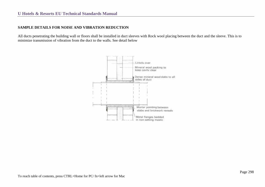
U Hotels & Resorts EU Technical Standards Manual
Page 298 To reach table of contents, press CTRL+Home for PC/ fn+left arrow for Mac
SAMPLE DETAILS FOR NOISE AND VIBRATION REDUCTION
All ducts penetrating the building wall or floors shall be installed in duct sleeves with Rock wool placing between the duct and the sleeve. This is to
minimize transmission of vibration from the duct to the walls. See detail below

U Hotels & Resorts EU Technical Standards Manual
Page 299 To reach table of contents, press CTRL+Home for PC/ fn+left arrow for Mac
SIGNAGE
OUTDOOR SIGNAGE
General
Hotel Name
Pre – Opening / Construction Boards
Traffic Signage
Car Park Signage
Access Signage
Identification Plate
Technical Specifications
INDOOR SIGNAGE
General
Directional Signage
Information Signage
Commercial Signage
Banqueting Signage
Floors Numbering
Guest Rooms Numbering
U Hotels & Resorts EU Technical Standards Manual
Page 300 To reach table of contents, press CTRL+Home for PC/ fn+left arrow for Mac
OUTDOOR SIGNAGE
GENERAL
Refers to outdoors signs, (luminous or illuminated), including access signs, canopy signs or roof signs etc.
Also refers to outdoor directional signage, including street signs for vehicles or pedestrians.
HOTEL NAME
The total specific name, as defined in the Hotel Brief, with a dedicated name followed by the geographical location, will be drawn according to
standard graphics (example “U Chiang Mai”, “U Zenmaya Phuket” or “U Sukhumvit Bangkok”).
PRE – OPENING/CONSTRUCTION BOARDS
During site construction pre-opening boards, illuminated at night, will be installed at strategic positions to be visible to road and pedestrian traffic.
TRAFFIC SIGNAGE
Road signs installed on the main traffic streets will clearly lead to the hotel where possible
CAR PARK SIGNAGE
Any directional signage will be as per local road signage.
ACCESS SIGNAGE
A sign indicating the hotel name will be installed at the property entrance. It will be illuminated in all cases.
Different signage regulations may apply depending on the location of the property. Please contact your local authority for information and guidance.
In some countries, such as Thailand and due to the signboard tax rate, there should be local script on top (left or right corner) of signage above any
graphic elements. The designer should refer to the local authority for regulations.
Size and location will be defined in order to obtain a good perception before entering the property.
IDENTIFICATION PLATE
The identification plate is in bronze or stone and installed near the main entrance door. It must indicate the hotel and city name.

U Hotels & Resorts EU Technical Standards Manual
Page 301 To reach table of contents, press CTRL+Home for PC/ fn+left arrow for Mac
BUILDING SIGNAGE
A U logo installed on top of the building façade where it is easily noticed. The size shall be large enough to be viewed from a distance.
It will consist solely of the logo. No location name or other indicator is required.
TECHNICAL SPECIFICATIONS
Lighting
Signs are based on illuminated individual letters which can be illuminated:
either by individual lights integrated in each caisson letter
either by a back projection giving an illuminated background to each letter
or by direct lighting from projectors. In the latter case, the projectors must be positioned to avoid any nuisance to rooms or the hotel access and
environment.
They must be accessible and dismountable with a transformer for each letter.

U Hotels & Resorts EU Technical Standards Manual
Page 302 To reach table of contents, press CTRL+Home for PC/ fn+left arrow for Mac
Letters
The letters’ minimum height should be referred from size chart and letters and will be wide enough to be legible from a desirable distance
Typeface is “ Copperplate ” ( light or regular)
Letter colours will be chosen according to the background and preferably high contrast in order to maintain good visibility.
Materials
Letters will be made of steel with matte finish, anodised aluminium or aluminium with baked enamel lacquer.
Miscellaneous
In all cases, access will be provided for maintenance with hooks on top of the mural support.
Electrical outlets will be provided for an eventual gondola. The anchoring of signs and the signs themselves will be designed to resist exterior
elements.

U Hotels & Resorts EU Technical Standards Manual
Page 303 To reach table of contents, press CTRL+Home for PC/ fn+left arrow for Mac
ACCESS SIGNAGE DIMENSION GUIDELINE
Use only the approved logos from the Corporate Marketing Office
Clear space around logo according to “x” height as shown on top right
Clear space is the minimum space maintained around the logo. It also defines the minimum distance that the logo is placed from the edges.

U Hotels & Resorts EU Technical Standards Manual
Page 304 To reach table of contents, press CTRL+Home for PC/ fn+left arrow for Mac
OUTDOOR SIGNAGE

U Hotels & Resorts EU Technical Standards Manual
Page 305 To reach table of contents, press CTRL+Home for PC/ fn+left arrow for Mac
INDOOR SIGNAGE
GENERAL
Signage should be designed so as to be clearly perceived both by guests entering the hotel and ones already in residence coming down from the above
floors. Signage must allow the guest to be immediately aware of the direction of the various facilities of the hotel. Signage must inform guests about
current activities and promote points of sale. Also required for service areas and fire safety. Positioned so as to not create potentially dangerous obstacles.
Interior signage should be designed and implemented on a property to property basis which should be influenced by the interior design of the property in
terms of size, colour and placement with the exception of fire and safety signage which must be in accordance with specific local or international
regulations. The typeface and font used for related signage must be in accordance with the brand identity manual.
DIRECTIONAL SIGNAGE
Rooms Accessible by Guests
These are directional signals as well as room identification, such as numbers for bedrooms and floors, washrooms, offices, service etc. These signs
should be easily legible and especially designed from the standpoint of permanent lighting. They should be in full harmony with the decor and
interior architecture.
Typeface is Copperplate (light, regular) or Goudy Old Style (regular, bold)
Guest Elevators
Signage includes:
Floor numbers facing elevator doors or on the door frames
Wall-mounted directory listing the public areas of each level near the call button box in the cabins
Non-smoking floors indicated next to floor buttons in the elevator cars

U Hotels & Resorts EU Technical Standards Manual
Page 306 To reach table of contents, press CTRL+Home for PC/ fn+left arrow for Mac
Indoor Car Park
Signage includes:
Proximity signs indicating the direction or location of car parks
Entry and exit signs
Access sign towards the elevators lobby for access to the hotel lobby in the case of an underground car park.
Floor markings: yellow lines, arrows, parking bays, parking bay numbers and car park level.
Back of the House
Signage includes:
Administrative offices: designation of each office and directional signage
Technical rooms: designation of each room
Service areas: designation of each room
Service lifts: floor number in front of lift doors
This signage will be made from materials of a lesser quality as ones in public areas, but always maintaining a coherence of design and format graphics.
Fire Safety
Signage includes:
Floor plans on guest elevators landings
Notice board and plan on back of guest room doors
Logos on fire stairs doors
Floor numbers on each landing at the fire exit, facing the door
Arrows indicating the direction (up or down to find the exit in the fire stairwell)
Location of fire hoses and fire extinguishers

U Hotels & Resorts EU Technical Standards Manual
Page 307 To reach table of contents, press CTRL+Home for PC/ fn+left arrow for Mac
Miscellaneous
These also must be provided:
Notice board for guestroom rates and hotel liability, (to be fixed with discretion in the guest room entry cupboard) (see also local regulations).
Signage for smoking and non-smoking zones
Disabled signage (toilets, car parks)
Any extra signage required by local regulations
INFORMATION SIGNAGE
Information Boards (changeable signs)
Refers to:
Temporary information which lists the hotel’s daily events, meetings etc
Permanent information such as posters for bars and restaurants,
These different information boards are constituted by wall-mounted boards or panels with electronic displays.
Their usual locations are the lobby, ballroom access and elevator landings.
They will be integrated in the Interior Design Project and illuminated by direct lighting.

U Hotels & Resorts EU Technical Standards Manual
Page 308 To reach table of contents, press CTRL+Home for PC/ fn+left arrow for Mac
COMMERCIAL SIGNAGE
Restaurants and Bars
Signs indicate the name at the entrance of points of sale to attract guests.
Graphics will be studied following names defined in the Hotel Brief. They will be drawn by the Interior Designer or the Graphics Consultant.
Menus will have the same typeface as these signs.
BANQUETING SIGNAGE
Each meeting room name will be indicated on a programmable electronic display, (part of 2.3 above), to temporarily indicate the function name
in the room and the current activities.
FLOOR NUMBERING
A number corresponding to each floor, as indicated in the elevators and key tags:
o 2ND basement: B2
o 1st basement : B1
o ground floor : G
o 1st floor : 1
o 2nd floor : 2
Number 13 is deleted for floor levels.
The first number (or the first two in the case of more than 10 floors) of each number therefore indicates the floor.
U Hotels & Resorts EU Technical Standards Manual
Page 309 To reach table of contents, press CTRL+Home for PC/ fn+left arrow for Mac
GUEST ROOM NUMBERING
The two (or three) last figures indicate the number of the room on the floor.
Operating
A vertical alignment of room numbers should be respected if possible.
On each floor, the room with the smallest number is the furthest away from the lift landing, turning left.
For this to have any meaning where there is an even side and an odd side, the rooms opposite each other have consecutive numbers. (i.e. =
some numbers can be omitted, in order to follow this rule).
Room number 13 will be excluded. Other auspicious numbers depending on location and owner’s preferences will need to be considered.
The top of room number sign should be at 1600mm from floor level.
Position room number sign on the wall adjacent to the door frame, not on the door panel.
Design
Lettering and background should be of high contrast. Black on white or white on black provide maximum contrast.
When using colours, tones are important. Light colour letters on a dark background is advisable.
A sign must be visible in daylight and at night. Efficient lighting is required for guests to see the sign clearly.
When a sign is illuminated, the light source must be shielded from the viewer to prevent glare.
The surface of the sign should have a matt finish to reduce reflection and glare.
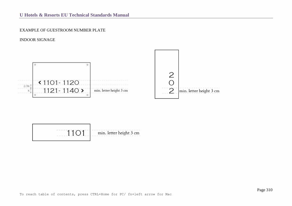
U Hotels & Resorts EU Technical Standards Manual
Page 310 To reach table of contents, press CTRL+Home for PC/ fn+left arrow for Mac
EXAMPLE OF GUESTROOM NUMBER PLATE
INDOOR SIGNAGE

U Hotels & Resorts EU Technical Standards Manual
Page 311 To reach table of contents, press CTRL+Home for PC/ fn+left arrow for Mac
LEGIBILITY CHART

U Hotels & Resorts EU Technical Standards Manual
Page 312 To reach table of contents, press CTRL+Home for PC/ fn+left arrow for Mac
EXAMPLE OF INDOOR SIGNAGE LEVEL

U Hotels & Resorts EU Technical Standards Manual
Page 313 To reach table of contents, press CTRL+Home for PC/ fn+left arrow for Mac

U Hotels & Resorts EU Technical Standards Manual
Page 314 To reach table of contents, press CTRL+Home for PC/ fn+left arrow for Mac
INDOOR SIGNAGE
EXAMPLE OF ROOM NUMBERING

U Hotels & Resorts EU Technical Standards Manual
Page 315 To reach table of contents, press CTRL+Home for PC/ fn+left arrow for Mac
EXAMPLE OF SIGNAGE LAYOUT

U Hotels & Resorts EU Technical Standards Manual
Page 316 To reach table of contents, press CTRL+Home for PC/ fn+left arrow for Mac
EXAMPLE OF SIGNAGE DRAWING

U Hotels & Resorts EU Technical Standards Manual
Page 317 To reach table of contents, press CTRL+Home for PC/ fn+left arrow for Mac
EXAMPLE OF SIGNAGE DRAWING

U Hotels & Resorts EU Technical Standards Manual
Page 318 To reach table of contents, press CTRL+Home for PC/ fn+left arrow for Mac
EXAMPLE OF SIGNAGE DRAWING
SIGNAGE AT GUESTROOM DOOR

U Hotels & Resorts EU Technical Standards Manual
Page 319 To reach table of contents, press CTRL+Home for PC/ fn+left arrow for Mac
EXAMPLE OF SIGNAGE DRAWING
SIGNAGE AT GUEST ELEVATOR

U Hotels & Resorts EU Technical Standards Manual
Page 320 To reach table of contents, press CTRL+Home for PC/ fn+left arrow for Mac
THE DISABLED
Access
Public Areas
Signage
Elevators

U Hotels & Resorts EU Technical Standards Manual
Page 321 To reach table of contents, press CTRL+Home for PC/ fn+left arrow for Mac
An approved international set of rules and regulations will apply if there are no local regulations. Local regulations will supersede the below.
ACCESS
Main Entrance
If the entrance is higher than the sidewalk, a ramp will be provided in order to avoid any steps. Slope must be according to the local regulations.
U Hotels & Resorts EU Technical Standards Manual
Page 322 To reach table of contents, press CTRL+Home for PC/ fn+left arrow for Mac
PUBLIC AREAS
These must all be accessible and usable by individuals with disabilities, as much as possible without assistance.
Steps will be avoided and if there are any, provide a ramp with a maximum slope of 4%. Slightly higher slopes are possible for shorter runs in
case of absolute necessity (see attached sketches). The height of any riser on the routes of the disabled will not exceed 4 cm (bevelled) or 2 cm
(straight). The maximum cross-slope is 2 %.
The ramps have an attached handrail when more than 40 cm high and landings. Landings will have a minimum size of 1.20 × 1.40 m.
The main access routes have a minimum width of 1.40 meters and secondary ways of 0.80 m. Doors shall leave a clear passage of at least 90
cm, or 80 cm for doors leading to small rooms (such as toilets, bathrooms and elevators).
All the items to be handled, whether switches, telephones, lift call buttons, automatic vending machines, ice cube dispensers, counters, mirrors,
handrails and grab bars will be placed at heights that can be used by the disabled. (Maximum: 130 cm, minimum: 40 cm for the accessible
parts).
Public toilets will have, at each accessible level, a stall accessible to men and one for women, with adequate clear turning space, equipment and
amenities.
At least one elevator should be fitted for handicap customers which should be marked on the ground floor

U Hotels & Resorts EU Technical Standards Manual
Page 323 To reach table of contents, press CTRL+Home for PC/ fn+left arrow for Mac

U Hotels & Resorts EU Technical Standards Manual
Page 324 To reach table of contents, press CTRL+Home for PC/ fn+left arrow for Mac
SIGNAGE
Signage should be able to be read by the disabled and the children.
Besides areas where information is necessary (car parks, public toilets, lifts) no specific signage will be provided.
Pathways and premises accessible to the disabled must be indicated with the international symbol

U Hotels & Resorts EU Technical Standards Manual
Page 325 To reach table of contents, press CTRL+Home for PC/ fn+left arrow for Mac
ELEVATORS
Elevator call buttons can include Braille numbers and a sound level indicator.
Elevator cabin
Minimum size: 100×130 cm
Minimum weight: 630 kg - 8 people
Necessary for sliding doors: minimum passage width: 80 cm.

U Hotels & Resorts EU Technical Standards Manual
Page 326 To reach table of contents, press CTRL+Home for PC/ fn+left arrow for Mac
WATERPROOFING
General Notes
Roof Terrace
Car Park Terrace
Traditional Forms of Roof
Glass Roofs
Swimming Pool – water tank
Floors

U Hotels & Resorts EU Technical Standards Manual
Page 327 To reach table of contents, press CTRL+Home for PC/ fn+left arrow for Mac
GENERAL NOTES
Particular attention must be paid to waterproofing which must carry a 5-10 year guarantee depend on item and location.
Various processes can be employed provided that these always comply with regulations and the licensing conditions for products used.
Terraces which are visible from public rooms will be laid out in such a way as to produce decorative effects, examples of this being geometric
designs, use of several colours or landscaping.

U Hotels & Resorts EU Technical Standards Manual
Page 328 To reach table of contents, press CTRL+Home for PC/ fn+left arrow for Mac
ROOF TERRACE
By way of example, the following forms of waterproofing can be used for straight sections:
o poured asphalt
o multi-layer systems: reinforced bitumen and bitumen-coated felt
o Elastomeric membrane.
The waterproofing system will be established with a slope (minimum 2%) and will incorporate thermal insulation as well as the required up
stand and flashing.
Protection is provided by a layer of gravel (minimum 4 cm) or the waterproofing system will have its own protection.
For areas accessible to the public or service areas around technical facilities, protection will be provided by concrete flagstones on supports or
on a sand + Kraft paper separating layer.
Any parapet up stand is to be protected by a ledge; any expansion joint will be protected by metal capping.
Special Points
These points are for those which display the most risk and have to be given particular attention (chimney outlets, waste vents, and rainwater
inlets). Up stands must be protected.
Removal of Rain Water
Different systems can be considered: sealed gratings, overflows etc. Any rainwater inlet must not involve a catchment area of more than 700 m²
and there must be at least two inlets per catchment area.

U Hotels & Resorts EU Technical Standards Manual
Page 329 To reach table of contents, press CTRL+Home for PC/ fn+left arrow for Mac
CAR PARK TERRACE
If there is a terrace accessible to motor traffic, the multi-layer-waterproofing complex must be protected:
by a hot-applied bituminous coating (minimum 4 cm) for heavy-duty parking spaces (up to 13 tons per axle)
by self-locking flagstones placed on a bed of sand for light-duty parking spaces (less than 2 tons per axle).
U Hotels & Resorts EU Technical Standards Manual
Page 330 To reach table of contents, press CTRL+Home for PC/ fn+left arrow for Mac
TRADITIONAL ROOFING (tiles, slates, shingles, zinc, copper etc.)
Care must be taken to see that these are properly placed with a slope which must lie between certain limits which are compatible with the material and
its method of attachment.
Examples:
Slates : minimum incline 30% - maximum incline vertical
Roman tiles : minimum incline 25% - maximum incline 40%
Shingles : minimum incline 20%
Wooden shingles : minimum incline 33%
Galvanized steel pans : prohibit any contact with copper or lead,
Tin and untreated steel
Painted aluminium pans : only use sheets which have been given a factory-applied heat bonded enamel coat
It is recommended that an incline greater than 5 mm/m is used for troughs and gutters.
U Hotels & Resorts EU Technical Standards Manual
Page 331 To reach table of contents, press CTRL+Home for PC/ fn+left arrow for Mac
GLASS – ROOFS
Glass
This is the material to be preferably used. It is recommended that laminated glass be used.
Plastic Materials
Failing the use of glass, the project may use polycarbonate in preference to any other material in order to achieve good UV resistance and to
prevent yellowing and cracking with time.
U Hotels & Resorts EU Technical Standards Manual
Page 332 To reach table of contents, press CTRL+Home for PC/ fn+left arrow for Mac
SWIMMING POOL – WATER TANK
Waterproofing is achieved using various processes:
o incorporated into the reinforced concrete mass
o by applying a smoothing coat then a sealing coating of strong cement mortar with incorporation of a water-proofing agent applied in
successive layers to give a total thickness of 30 mm,
o by thick cladding of reinforced resin.
For swimming pools, a finish of large-size tiles is essential.
In seismic areas, a technical solution will be selected which will allow seismic movements and cracks which might result from them in the
concrete shells to be absorbed.
Where possible, one should avoid having swimming pools or sheets of water which are placed above inhabited rooms.
If this cannot be avoided, particular attention must be paid to waterproofing.

U Hotels & Resorts EU Technical Standards Manual
Page 333 To reach table of contents, press CTRL+Home for PC/ fn+left arrow for Mac
FLOORS
Waterproofing is also required for certain interior floors:
o kitchens and annexes
o laundries
o employee locker rooms and toilets
and in certain special cases:
o bathrooms (floor drains)
o balconies above inhabited rooms.
U Hotels & Resorts EU Technical Standards Manual
Page 334 To reach table of contents, press CTRL+Home for PC/ fn+left arrow for Mac
EXTERIOR JOINERY (WOOD AND METAL WORK AND GLAZING)
Water Proofing – distortion
Wood Joinery
Metalwork
Mixed Units
Glasswork – glazing
Railings
Maintenance

U Hotels & Resorts EU Technical Standards Manual
Page 335 To reach table of contents, press CTRL+Home for PC/ fn+left arrow for Mac
WATERPROOFING - DISTORTION
The characteristics of sound external joinery are:
o water tightness
o air tightness
o ability to withstand high wind pressures without excessive distortion
o fire resistance, in relation to conditions of use and current regulations concerning sound insulation
All joinery, metalwork and glazing installed must have a test certificate guaranteeing good results in the areas mentioned above.
Greater or lesser requirements as to such results may be needed, depending upon exposure of facades and the level of winds.
In addition, facades will be designed in such a way as to absorb any foreseeable expansion without making noise.
WOOD JOINERY
The material used for wood joinery will be selected in relation to the climate (tropical or temperate).
Wood joinery must be of additional thickness in maritime zones.
It must be treated with insecticide and fungicide products either by injection under pressure or by immersion. If a product is impregnated, it
must not wash off.

U Hotels & Resorts EU Technical Standards Manual
Page 336 To reach table of contents, press CTRL+Home for PC/ fn+left arrow for Mac
METALWORK
Metalwork must only be installed when the shell has been completed, in order to avoid any risk of deterioration or temporary removal and the premises
and apertures must have been cleaned. To a large extent, the quality of waterproofing and good function depends upon the quality of finish of the shell
into which they are installed.
There must be no gaps in weld seams. Traces of welding must be removed by grinding and polishing so that they do not detract either from the
appearance or the waterproofing quality of the work.
It must be possible to take out door leaves and mechanisms without having to remove the entire frame.
All along the frames there must be devices for collection and removal of rainwater drips and water created by condensation. Rooms in which
high condensation may occur must have a system for taking water to the outside.
Slide tracks for sliding door panels must be located at the bottom. It must not be possible for sliding doors to jump from the frames.
Contact between different metals must be avoided, particularly in moist locations.
Where access can be gained to ground floor rooms from outside, external doors and windows will be provided with locks which will use the
same key as that for the entrance door to the room.
Aluminium Frames
They must be anodized (20 minimum) or given a heat-bonded lacquer coat at the factory.
Rollers, made preferably of Teflon, must guarantee that sliding units operate properly.
There must be a high quality closure system with security device.
Steel Frames
They must be given anti-corrosion treatment which is of superior quality and finish.
In no circumstances must they be used at seaside locations (corrosive atmosphere).
When using stainless steel, use 304L or 316 L in a seaside location.
Hardware
Hardware and screws must be completely stainless and suitable for the frames used.

U Hotels & Resorts EU Technical Standards Manual
Page 337 To reach table of contents, press CTRL+Home for PC/ fn+left arrow for Mac
MIXED UNITS
These units have the advantage of combining the durability of a metal external section and the aesthetic of a wooden internal face.
They can be used where it is desired to avoid any thermal bridge in the façade.
GLASSWORK AND GLAZING
Coloured Glass
Coloured or reflective glass must be installed to reduce heat (particularly for air-conditioned rooms).
All tinted glass must be tempered.
Compound Glass
For sky domes it is essential that laminated glass be used (which is both tinted and reflective) in order to prevent unreasonable consumption of energy
for air conditioning.
Tempered Glass
Glazing for doors and external glazed partitions on the ground floor must be tempered glass. Such glass is to be marked by adding a decorative
emblem at eye level.
Mirrors
Silvering on mirrors will have a minimum thickness of 5 microns. The glass will be slightly separated from its supports in order to allow air
circulation. Mirrors will be secured by mechanical means (wall fixings).

U Hotels & Resorts EU Technical Standards Manual
Page 338 To reach table of contents, press CTRL+Home for PC/ fn+left arrow for Mac
RAILINGS
These must be designed with especially durable materials so as to allow for intensive use without risk and long lasting quality over time.
The handrail and framework of the railings must be of a type requiring minimum maintenance (heat-bounded lacquered aluminium, stainless
steel, impregnated wood etc.).
MAINTENANCE
Suitable fittings will be provided to allow for cleaning and maintenance of glazing and frames: a cradle will be installed if it is not possible to
carry out the work easily.
In particular, bedroom window frames must be of an opening type or must have an opening section to allow for easy cleaning.

U Hotels & Resorts EU Technical Standards Manual
Page 339 To reach table of contents, press CTRL+Home for PC/ fn+left arrow for Mac
INTERIOR JOINERY
Bedroom Doors
Doors of Common Areas
Technical Facilities Access Doors
Panelling, Skirting and Cornices
Sound Insulation Partitions
Bar Counter
Rear of Bar Furnishings
Reception Desks

U Hotels & Resorts EU Technical Standards Manual
Page 340 To reach table of contents, press CTRL+Home for PC/ fn+left arrow for Mac
BEDROOM DOORS
Entrance Doors
These are solid-core with minimum dimensions of 830 x 2,040 mm
They are equipped with a spy hole, concealed door closer and door stop with hold-open position.
Protective plates are placed around handles and locks. Metal doorframes should be avoided for acoustic reasons.
Particular attention must be paid to sound insulation. Doors will be provided with a peripheral sound reduction strip of neoprene. Doors and
frames will be double rebated.
They must be flame-resistant for 90 minutes.
The door must also fit as flush as possible to the finished floor level. Under no circumstance must the gap be used for air renewal for the
bedroom.
Internal Doors
These are the WC and bathroom doors.
They will be equipped with doorstops and sound buffers.
Protection plates will be placed around locks and handles.
They will have devices allowing them to be locked from the inside with the possibility of release from the outside.
Depending on the MEP design it may require louvers for air circulation.
Closet Doors
Doors will preferably be of the sliding type. The door casing on the front of the cupboard with sliding doors must be independent of the
adjacent partitions, by insertion of expandable joints.
The width of the sliding panels must be no less than 2/5 of the height.
They will be suspended on nylon rollers and equipped with sound buffers.
They can be fitted with an external full-length mirror.
For details of drawers, clothing rods and cupboard shelves, see section C3 - Rooms.

U Hotels & Resorts EU Technical Standards Manual
Page 341 To reach table of contents, press CTRL+Home for PC/ fn+left arrow for Mac
DOORS OF COMMON AREAS
These are connecting doors between public areas, doors between a service area and a public area, interior doors within service areas and doors
of technical facilities.
They will have a fire rating in accordance with regulations.
Door closers, doorstops and soundproofing joints will be used for all floors.
Service doors will be provided with a glass panel, particularly between the kitchen area and the restaurant rooms.
Where doors separating service rooms (kitchens, floor service rooms, technical facilities rooms) from public rooms (restaurants, passageways,
bars), are concerned, these will be given sound insulation by means of an all-round soundproofing strip. They will open from public areas by
pulling, in order to limit damage to the front panel by trolleys and carts (except for emergency exits). Special care will be given to their front
finish.
They must have a minimum thickness of 40 mm and if of single leaf type must have minimum dimensions of 900 x 2,040 mm.
Doors giving onto service rooms are protected by separate protection plates and plinths and kick plates where carts are used or hands are not
free (e.g. = kitchens).
Emergency exits must be capable of being opened when pushed (panic bars).

U Hotels & Resorts EU Technical Standards Manual
Page 342 To reach table of contents, press CTRL+Home for PC/ fn+left arrow for Mac
TECHNICAL FACILITIES ACCESS DOORS
Conference Modules Cabinet Doors
These will have clear dimensions of 200 x 50 cm. They comprise of:
a sub-frame of hardwood fixed to the wall
a hardwood frame
a solid door leaf 40 mm thick of exotic wood swinging on invisible hinge plates
The door leaf has a built-up facing in harmony with the decoration of the walls.
The plinth of the door leaf is hinged horizontally onto the door leaf so that it can be lifted and must form an aperture which allows for electric wires
and cables connected in the cabinet to pass through.
Opening Panels of Control Panels
They comprise of:
a frame of hardwood fixed to the wall
a solid-core panel 20 mm thick of exotic wood swinging on invisible hinge plates
The panel has a built-up facing in harmony with the decoration of the walls; closed by bolt and has a knob on the front of the facing.
Doors of Technical Shafts
They comprise of:
a sub-frame of hardwood fixed to the wall, having in its lower portion a horizontal strip for attachment of the room skirting
a hardwood frame
a solid-core door leaf 40 mm thick of exotic wood swinging on invisible hinges

U Hotels & Resorts EU Technical Standards Manual
Page 343 To reach table of contents, press CTRL+Home for PC/ fn+left arrow for Mac
The door leaf has a built-up facing in harmony with the decoration of the walls.
Doors are locked and tied to the hotel key-chart.
PANELLING SKIRTING, MOLDINGS AND CORNICES
Panelling is fashioned from flat lathe panels or similar with a low flammability rating (M1), with wood cladding protected at the bottom by
skirting.
Half height panels have at the top moulding, the height of which will be specified so as to give protection to the dado and wall from scraping by
chair backs.
Full height panels have a cornice at the top which links up with the false ceiling.
Wall mouldings, skirting, borders and cornices are of solid wood.
Panelling is positioned so as to allow free circulation of a strip of air between the wall and the back of the elements which form the panelling.

U Hotels & Resorts EU Technical Standards Manual
Page 344 To reach table of contents, press CTRL+Home for PC/ fn+left arrow for Mac
SOUND INSULATION PARTITIONS
Partition walls must have a minimum in-situ installed acoustic attenuation factor of 45 dB (DnTA or NR), i.e. of at least STC 48 to 50.
Every measure must be taken to give sound insulation in the top portion from the concrete beam as far down as the suspender rail including the
metal supporting beam, so as to eliminate any sound bridge.
The panels will have metal protection against trolleys and must be 100 mm minimum thickness.
There must not be any floor rail.

U Hotels & Resorts EU Technical Standards Manual
Page 345 To reach table of contents, press CTRL+Home for PC/ fn+left arrow for Mac
BAR COUNTER
This is made up from solid-core waterproof panels of low flammability rating (M1), for all frontal, return and internal structure elements.
The panels must incorporate any apertures, cut-outs and recesses needed for installation of bar equipment:
o hot and cold water supply
o sink and draining board
o ice cube container
o connections for supply of electricity, computer system and telephone
o incorporation of refrigeration equipment
o Incorporation of and power supply for a glass washing unit.
The upper horizontal panel and the structure are designed to carry a tablet of high grade material and any other decorative facings specified by
the interior designer.
On the inside a satin-finish stainless steel work surface placed on a waterproof panel must incorporate all necessary apertures and cut-outs.
The link between the work surface and the lower face of the decorative counter is likewise made of stainless steel.
There must be a flashing around the stainless steel panel in order to prevent water from running off.
The equipment beneath the work surface includes:
o Sliding lockable drawer units running on telescopic runners
o Storage with fronts made of solid-core panels (M1) closed by invisible spring hinges, with mortise locks and internal panels of
laminated board on aluminium racks.

U Hotels & Resorts EU Technical Standards Manual
Page 346 To reach table of contents, press CTRL+Home for PC/ fn+left arrow for Mac
REAR OF BAR FURNISHINGS
In general, these furnishings comprises of:
o a high unit with shelving for bottles, frames for glasses and a niche to hold a coffee machine placed on the low unit top.
o a low unit with sets of sliding drawers, refrigerated storage, sage storage and possibly storage for bar sound equipment.
Made of solid waterproof panels, rated as low flammability (M1).
The panels will incorporate any apertures and cut-outs necessary for installation of the coffee machine.
The niche which is intended to hold the coffee machine has a backing of insulating material and a stainless covering sheet in order to facilitate
cleaning.
The top portion of the niche also includes a removable grille for steam extraction by flexible tubular sleeve which is connected to the general
extraction system.
Doors of refrigerated units have all necessary insulation layers.
Around the doors of refrigerated units there are recessed rubber joints with counter-rebates.
All doors are kept closed by handles with integral locks.
RECEPTION DESKS
Facilities beneath the work surface include:
sets of sliding drawers on telescopic runners with locks
recesses for baskets, with integral opening front panels, swung from invisible hinges and closed by magnetic catches
low tops on telescopic runners for printers
a removable false panel to allow for insertion of cables and inspection for maintenance.

U Hotels & Resorts EU Technical Standards Manual
Page 347 To reach table of contents, press CTRL+Home for PC/ fn+left arrow for Mac
LOCKS
General
Electronic Locks
Conventional Locks
Key Chart

U Hotels & Resorts EU Technical Standards Manual
Page 348 To reach table of contents, press CTRL+Home for PC/ fn+left arrow for Mac
GENERAL
All guestrooms must be fitted with electronic locks operated by RFID key cards.
The supplier’s choices for both conventional and electronic locks should be submitted to U Hotels and Resorts Management for approval before
any order is placed.
The finishes shall be adapted for use and chosen in agreement with the interior designer.
Only locks of superior quality will be selected. They will be tropicalized or guaranteed for seaside use where applicable.
No padlocks are acceptable in any situation.

U Hotels & Resorts EU Technical Standards Manual
Page 349 To reach table of contents, press CTRL+Home for PC/ fn+left arrow for Mac
ELECTRONIC LOCKS
Electronic locks should generally be fitted as guestroom locks only.
In specific cases, and as per the Hotel Brief, they can also be used for public (e.g. Conference rooms) and service (e.g. Stores) areas.
Operation
The system could comprise of the following:
a central processing unit with a monitor, printer, identifier-encoder and inverter located in the computer room
identifier-encoders at reception
identifiers in the Front Office Manager’s office, at restaurants and bar cashier counters.
a portable dialogue computer for reading the information stored in locks
battery-powered electronic locks
RFID key or magnetic-strip key cards with unlimited reprogramming capacity
Key Cards
Encoding:
Cards will be encoded at reception using an encoder when customers are allocated a room.
Advance encoding with limited date/time validity:
The operator may create a guest room key card in advance (once a reservation has been made). The key card will then be usable only for the
duration of the guest’s stay.
Encoding of different cards for one guest room in the event of multi-occupancy in that room.
Instant encoding in the event of loss:
A new card can be created immediately with a different code should a guest lose their key card.

U Hotels & Resorts EU Technical Standards Manual
Page 350 To reach table of contents, press CTRL+Home for PC/ fn+left arrow for Mac
Guest Key Cards
Simple graphics, on the same side as the chip, should be used to indicate how to insert the card into the lock.
The card must be water and heat-resistant and fit easily into a pocket or wallet.
The reverse of the card may be used for advertising or for displaying the hotel logo.
Front Back

U Hotels & Resorts EU Technical Standards Manual
Page 351 To reach table of contents, press CTRL+Home for PC/ fn+left arrow for Mac
Key Cards for Employees’ Use Only
Encoder card:
Allows access to and use of the encoder on input of a password.
Emergency key card:
The emergency key card should open all door types in case of emergency (even if they are locked from the inside).
Master key card:
Able to unlock all doors (except for guestroom doors locked from the inside).
Card giving access to a floor, building or department:
As a function of the hotel’s operational organization and hierarchy, this card should authorise access by employees to specific floors,
buildings and departments within pre-programmed time limits. Access is not authorized if the door is locked from the inside.
“Initialisation” card:
Initialises the encoder and the locks on system start-up.
“Prohibit” card:
Prohibits customer access to a guestroom where necessary.
“Customer re-authorisation” card:
Restores the original conditions. This card is only used after the “prohibit” card.
“Employee prohibit” card:
Prohibits employee’s access to a bedroom at a customer’s request, or for any other reason.
“Employees re-authorisation” card:
Restores the original conditions. This card is only used after the “employee prohibit” card.
“Test” card:
Used during maintenance to carry out a series of checks on the lock.
“Cleaning” card :
Used for periodic cleaning of the card reading head.
Blanks
The system should initially be supplied with sufficient blanks to cover six months’ operation, with at least 6 passes of each kind.
The manufacturer must guarantee future supply of blanks and their price, and print to them with the text agreed by U Hotels and Resorts
Management.

U Hotels & Resorts EU Technical Standards Manual
Page 352 To reach table of contents, press CTRL+Home for PC/ fn+left arrow for Mac
Locks
A closed door is always automatically locked.
The lock should comprise of:
a door-knob, with latch function
a security counter-latch
an interior dead-bolt (one inch) locking system with indicator, which can be unlocked from the outside in case of emergency
the external control plate with the computer reader and knob
the internal plate, with knob and dead-bolt control
the mortise-type mechanical casing
Electronic Accuracy
When a card is inserted, the microcomputer reads it, compares it instantly with all the data stored, and authorizes or prohibits access.
Alternatively, it may check the time validity of the card by comparing the encoded data with the data on the clock inside the electronic unit. An
auxiliary memory is used to store the last 150 card codes used in the lock. The codes can be read or printed out easily. Each opening of the lock,
and each attempt to open the lock, is stored in the memory with an indication of user identity and date/time.
Compliance with Safety Standards
The lock should be reversible, with an anti-intruder device and a panic-opening facility on the inside.
The dead bolt should lock the latch when the door is closed, preventing any attempt to force the lock.
The customer must be able to ensure privacy be turning a control on the inside to lock the dead bolt.
To exit the room, turning the knob on the inside should activate both the latch and the dead bolt.
Battery Power Supply
The electronic lock should be supplied with power by alkaline batteries with a guaranteed lifespan of more than one year, assuming that the
door is opened ten times per day on average.
The batteries should be located on the outside to allow them to be replaced without opening the door.

U Hotels & Resorts EU Technical Standards Manual
Page 353 To reach table of contents, press CTRL+Home for PC/ fn+left arrow for Mac
Indicator Lights
Two lights on the external plate should indicate the following:
green: access authorized
red: card read error or card not valid
red and green: batteries low
Portable Dialogue Computer
The portable dialogue computer should be capable of communication with both the electronic locks and the encoder.
Programming:
Transfers the initialisation data to the locks; fulfils the same function as the initialization card.
Retrieval:
Retrieves the data (date, time and card identification) relating to the last 150 door uses from the auxiliary memory and transfers it to the encoder
for printing.
Test function:
Analyses faults. Power is supplied by rechargeable batteries (average lifespan 5 years).
Identifier-Encoder
Identifier-encoders should be capable of creating and checking cards, displaying codes and printing the information on the card.
They should be accessible only by using the attendant card, followed by a secret password.
Only the senior operator should be able to read, print or cancel all passwords.
The encoders should be supplied with electrical power, with a battery for memory back-up in the event of an electrical failure.
Central Processing Unit
The central processing unit should interface with the Property Management System.
It should also interface with the Point of Sale system for payment using key cards and charging back to a single customer invoice.
U Hotels & Resorts EU Technical Standards Manual
Page 354 To reach table of contents, press CTRL+Home for PC/ fn+left arrow for Mac
Key Cards used During Installation
During the pre-opening period of the hotel, all key cards used during installation should be returned to the hotel General Manager or
automatically invalidated, and the supplier should undertake not to keep any nor pass any on to any person without the approval of U Hotels &
Resorts.
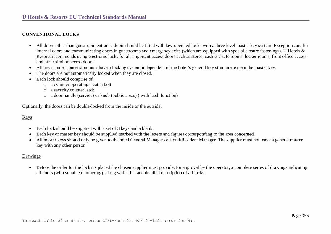
U Hotels & Resorts EU Technical Standards Manual
Page 355 To reach table of contents, press CTRL+Home for PC/ fn+left arrow for Mac
CONVENTIONAL LOCKS
All doors other than guestroom entrance doors should be fitted with key-operated locks with a three level master key system. Exceptions are for
internal doors and communicating doors in guestrooms and emergency exits (which are equipped with special closure fastenings). U Hotels &
Resorts recommends using electronic locks for all important access doors such as stores, cashier / safe rooms, locker rooms, front office access
and other similar access doors.
All areas under concession must have a locking system independent of the hotel’s general key structure, except the master key.
The doors are not automatically locked when they are closed.
Each lock should comprise of:
o a cylinder operating a catch bolt
o a security counter latch
o a door handle (service) or knob (public areas) ( with latch function)
Optionally, the doors can be double-locked from the inside or the outside.
Keys
Each lock should be supplied with a set of 3 keys and a blank.
Each key or master key should be supplied marked with the letters and figures corresponding to the area concerned.
All master keys should only be given to the hotel General Manager or Hotel/Resident Manager. The supplier must not leave a general master
key with any other person.
Drawings
Before the order for the locks is placed the chosen supplier must provide, for approval by the operator, a complete series of drawings indicating
all doors (with suitable numbering), along with a list and detailed description of all locks.

U Hotels & Resorts EU Technical Standards Manual
Page 356 To reach table of contents, press CTRL+Home for PC/ fn+left arrow for Mac
KEY CHART
Emergency key: able to lock, double-lock and unlock all internal and external doors even if double-locked.
Master key: able to lock and unlock all internal and external doors (except for double-locked doors).
Section master keys: able to open and close or double-lock all rooms/areas shown on the chart.
Partial master keys: able to open and close the rooms/area shown on the chart; unable to open or close double-locked doors.
Individual keys: able to open and close only the rooms/areas to which they are allocated.
Six copies of all master keys should be supplied.

U Hotels & Resorts EU Technical Standards Manual
Page 357 To reach table of contents, press CTRL+Home for PC/ fn+left arrow for Mac
CLOSURE
General Notes
Emergency Exits
Services Entrances
Loading Dock
Public Entrances
Underground Garage Entrance

U Hotels & Resorts EU Technical Standards Manual
Page 358 To reach table of contents, press CTRL+Home for PC/ fn+left arrow for Mac
GENERAL NOTES
The closure systems must prohibit or control access to the building, control admission of air and light and provide a screen against the wind,
rain and exceptionally bad weather as well as providing fire resistance in accordance with the requirements specified in section C-20 Fire
Safety.
Above all, they must protect the hotel against break-ins and must allow the hotel to be totally closed off, using the general passkey for the locks.
They are provided for exits, including:
o emergency exits
o service entrances,/entrances from the yard and from the loading dock
o public entrances
o underground garage entrance

U Hotels & Resorts EU Technical Standards Manual
Page 359 To reach table of contents, press CTRL+Home for PC/ fn+left arrow for Mac
EMERGENCY EXITS (See section T-13 IT & Low Voltage)
This covers all doors on emergency staircases and specific emergency exits used by employees and guests in the event of fire or danger.
All doors which are used as emergency exits must have a panic bar or some other approved device on the inside.
They are also locked by magnetic valves, so as to prevent any access from outside. Locking with electro-magnets and automatic unlocking are
linked to automatic systems for fire detection with, in certain cases, internal phones and monitoring cameras.
SERVICE ENTRANCES
These are metal swing doors which can be locked using the hotel passkey and which can be opened manually from inside as the leaves can be
unlocked simply by pushing.
LOADING DOCK
It must be possible to close off the dock by means of an electrically-operated metal curtain, a hinged grille or roller grille or as an alternative, a
wheel gate.
The type of system is selected in relation to the dimensions of the aperture to be closed off.
PUBLIC ENTRANCES
Numerous systems are envisaged for the main entrances of the hotel. These may involve:
o manual swing doors
o automatic sliding doors
o automatic or manual rotating doors

U Hotels & Resorts EU Technical Standards Manual
Page 360 To reach table of contents, press CTRL+Home for PC/ fn+left arrow for Mac
Swing doors and sliding doors must be of 2-stage type, forming an air lock. In all cases it must be possible to lock them using the hotel pass
key.
The number and dimensions of such doors are specified in relation to the amount of traffic and fire regulations for building evacuation in the
event of fire.
In all cases they will be equipped with tempered glass, possibly with metal frames to give protection from luggage trolleys, etc.
If doors are entirely of glass they are to have a discreet emblem (logo) + 1.50 m from ground level so that they can be easily visually identified
to avoid accidental collisions.
UNDERGROUND GARAGE ENTRANCE (managed by hotel)
Access to the garage must incorporate a total shut-off system by means of automatic doors.
Entrances to and exits from the underground garage are controlled by a system of automatic barriers with magnetic strip ticket, coin operated or
by guest key-cards. There must be supervision 24 hours a day by security in a cabin or possibly by centralised system of remote monitoring in
the case of a low capacity garage.
The automatic barriers can also be associated with an automatic till which is linked to the hotel cashier’s office, with internal phone and
invoicing system.

U Hotels & Resorts EU Technical Standards Manual
Page 361 To reach table of contents, press CTRL+Home for PC/ fn+left arrow for Mac
FINISHES
Summary Table
General Notes
Carpets
Tiles
Wooden Floors
Plastic Floors
Paint
Stretched Fabrics
False Ceilings
Lighting Fixtures
Doors

U Hotels & Resorts EU Technical Standards Manual
Page 362 To reach table of contents, press CTRL+Home for PC/ fn+left arrow for Mac
SUMMARY TABLE
Key
Floors Ceilings Doors - WC Woven carpet (category 1,2 or 3) - VP Wash-fast vinyl paint - ME Metal
- TC Tufted carpet - GP Wash-fast glycerophtalic paint - LA Laminated
- AR Rugs - ST Employees - PA Painted
- NT Non-slip tiles - AT Acoustic tile false ceiling - WF Wood faced
- VS Vitrified stoneware - AP Aluminium or lacquered steel pans - HG Tempered glass
- SM Stone, marble - WS Wooden slats - DE According to room decoration
- WF Wood floor - SC Special ceilings - SD Special door(fire rated, heat
insulated.)
- VT Vinyl tiles - AD Automatic door (tempered glass)
- FP Floor paint Lighting
- SC Special covering - I Incandescent lighting
- FF False floors - F Fluorescent lighting
- BP Bituminous paving - C Fluo-compact lighting
- L Chandelier
- B Box/Pan
Walls - S Spot
- VP Wash-fast vinyl paint - P Lamp on stand
- GP Glycerophtalic paint - W Sealed lighting unit
- WT Wall textile & flammability category - R Strip
- VC Vinyl covering - D Decorative lighting
- GT Glazed tiles - O Optical fibre
- CE Ceramic
- GL Glass paste
- SC Special cladding
- AC Acoustic cladding
- +V Vinyl base or wooden base for painting
- +H Hardwood base
- +R Protective railing
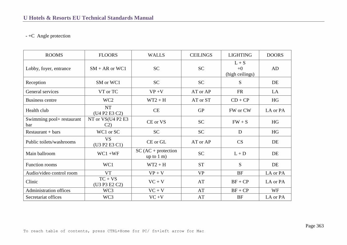
U Hotels & Resorts EU Technical Standards Manual
Page 363 To reach table of contents, press CTRL+Home for PC/ fn+left arrow for Mac
- +C Angle protection
ROOMS FLOORS WALLS CEILINGS LIGHTING DOORS
Lobby, foyer, entrance SM + AR or WC1 SC SC
L + S
+0
(high ceilings)
AD
Reception SM or WC1 SC SC S DE
General services VT or TC VP +V AT or AP FR LA
Business centre WC2 WT2 + H AT or ST CD + CP HG
Health club NT
(U4 P2 E3 C2) CE GP FW or CW LA or PA
Swimming pool+ restaurant
bar
NT or VS(U4 P2 E3
C2) CE or VS SC FW + S HG
Restaurant + bars WC1 or SC SC SC D HG
Public toilets/washrooms VS
(U3 P2 E3 C1) CE or GL AT or AP CS DE
Main ballroom WC1 +WF SC (AC + protection
up to 1 m) SC L + D DE
Function rooms WC1 WT2 + H ST S DE
Audio/video control room VT VP + V VP BF LA or PA
Clinic TC + VS
(U3 P3 E2 C2) VC + V AT BF + CP LA or PA
Administration offices WC3 VC + V AT BF + CP WF
Secretariat offices WC3 VC +V AT BF LA or PA

U Hotels & Resorts EU Technical Standards Manual
Page 364 To reach table of contents, press CTRL+Home for PC/ fn+left arrow for Mac
ROOMS FLOORS WALLS CEILINGS LIGHTING DOORS
Laundry VS
(U4 P3 E3 C2)
GT and VP
+C VP or AP FW
ME or
LA+ME
Linen room VT or VS (U3 P3 E2
C1) VP + V AP FB
ME or LA +
ME
Kitchen +
accessories
NT(U4 P3 E3
C2+rounded base GT and GP+C
Washable AP
with acoustic
insulation
FR recessed
LA + ME +
Special
protection
Loading platform FP GT VP FW ME
Storage VS VP VP FR ME
Cold stores VS
(U4 P3 E2 C2) GT VP
W+
protection grille SD
Trash/garbage NT
(U4 P3 E2 C2) GT VP FW ME
Employee locker and
washrooms
VS
(U3 P3 E2 C2) GT and VP VP or AP FB LA or PA
Employee cafeteria VS
(U4 P3 E2 C2) GP or VC+V AT FB LA or PA
Engineering areas FP VP VP FR SD
Workshops VT VP VP FR ME
Guestrooms WC3 or WF or SM +
AR VP or VC+H VP or ST IP +ID
Guestrooms entrance Ditto VP or VC+H ST or AT or WS S SD + WF or
DE
Guestroom bathrooms SM or VS CE or GL or SC ST or AP or WS CD LA or WF or
DE
Room corridors WC2 WT2 or VC+
H+R+C
ST or decorative
AT IS and FD WR or DE

U Hotels & Resorts EU Technical Standards Manual
Page 365 To reach table of contents, press CTRL+Home for PC/ fn+left arrow for Mac
ROOMS FLOORS WALLS CEILINGS LIGHTING DOORS
Pubic elevators SC SC SC CS or FD SD
Service elevators VT SC GP FR ME
Floor housekeeping pantry
NT or VT + brush
mat in front of door VP + V + C AP FR
LA or PA +
protection and
automatic door
closer
Service staircase FP + non-slip nosing VP VP FR LA or PA
Service corridors VT or VS (U4 P3 E2
C2) VP + R +C VP FR
ME+ signs +
protection
GENERAL NOTES
Care must be taken to see that the material is suitable for the purpose with regards to its resistance to wear, impact and chemical corrosion.
Particular attention will be paid to fire prevention regulations for the premises concerned.
A threshold must be inserted wherever the floor cladding changes.
The use of corner protection strips for any projecting angles of walls will be universally adopted in all service passageways, including certain
facilities.
U Hotels & Resorts EU Technical Standards Manual
Page 366 To reach table of contents, press CTRL+Home for PC/ fn+left arrow for Mac
CARPETS
Objectives
The technical (durability, maintenance), acoustic and aesthetic qualities of carpets constitute an important element of the brand image and comfort of
the hotel.
The intervals between replacements linked with operating economy is also a feature for consideration among the characteristics.
Technical Specifications WC1, 2 and 3
Weaving:
o Carpets will preferably be of the Wilton type or possibly Axminster (if the characteristics are as close as possible to those of Wilton
carpets).
o Synthetic carpets outside public rooms will be given anti-static treatment and will have the same characteristics as wool carpets. In
certain special exceptional cases, and only with U Hotels and Resorts Management approval, they may be used in guest rooms.
Treatment:
o if not synthetic, the backing will be treated against insects and fungi
o the treatment product must not be toxic
Colouring and design:
o the colour must go right through the carpet in a uniform manner
o a design and shade (1 to 5 by cards) will be specified by the interior designer and approved by U Hotels and Resorts Management before
an order is made.
Cleaning:
o the manufacturer is required to submit specifications (to avoid deterioration or discolouration) with their tender.
Fire resistance:
o they must be classified as “moderately flammable - difficult to ignite”.
Classification:
o The BS 7131 classification corresponding to the specifications required by U Hotels & Resorts is class 4 (heavy industrial use); T5 for
bedroom corridors, staircases and public zones and class 3 (or T4) (moderate industrial use) for bedrooms.
Laying:
o laying will be by stretching and fixing with nailed strips on a good quality felt underlay in all rooms accessible to customers i.e. public
rooms, passageways and guestrooms

U Hotels & Resorts EU Technical Standards Manual
Page 367 To reach table of contents, press CTRL+Home for PC/ fn+left arrow for Mac
at sites which display problems of hygiene (tropical environments, seaside etc. ) laying may be by means of adhesives using a double system of
adhesion (underlay + carpet)
laying will be by adhesive in offices.

U Hotels & Resorts EU Technical Standards Manual
Page 368 To reach table of contents, press CTRL+Home for PC/ fn+left arrow for Mac
TILES
Nature of Material:
Choice of tiles will be determined by the use required of them (see UPEC rating, as per NF/CSTB standard).
Whatever the precise nature of the material, they will always be of optimum quality.
Colours will be uniform.
Thickness tolerances will be a maximum of + 0.2 mm; dimension tolerances will be a maximum of + 0.5%.
Water absorption shall not exceed 3 to 7% of dry weight.
Care must be taken regarding resistance to atmospheric agents and to frost if outside.
Use
They will be laid in a totally flat manner, with the screed being used to correct any irregularities in the base. The plane surface will not display a
rise of more than 3 mm over a distance of 2 m taken in any direction.
Pipes and conduits may be allowed to run beneath the tiling provided that there is a covering of at least 5 mm in thickness. If pipes are required
to cross the tiling, the tiled surface must take into account any cut-offs and joints. Slopes of 1% will be provided in rooms that have floor
drains.
Ensure that inspection traps are installed.
There must be protective angles around any such traps (movable portion, fixed portion).
Joints
Tiles must always be laid with joints.
Areas of more than 60 m² with the same sealed covering must be interrupted by a joint, as well as at every 8 linear meters for any passageway.
In hot countries and those with a wide temperature range, the interruptions shall be at least every 30 m².
If the covered area is more than 12 m² a gap must be left between the last line of tiles and the vertical walls or pillars. This will be a peripheral
joint filled with laying mortar.

U Hotels & Resorts EU Technical Standards Manual
Page 369 To reach table of contents, press CTRL+Home for PC/ fn+left arrow for Mac
WOODEN FLOORS
Nature
Parquet strips must never be made from sapwood nor treated with hardener. Moisture content of the various constituent elements must not
exceed 20%.
Construction
The floor must be designed and constructed in such a way as not to give rise to any moisture coming up to the flooring.
Temperature of the base and the rooms must be above 5˚C, with ambient air that has a maximum humidity level of 70%.
The plane surface must not have any deflection of more than 5mm over two meters’ length in any direction.
The floors must be flush with the coverings of adjacent rooms with a maximum tolerance of +2 mm and with a threshold strip being used.
Insulation from impact noise will be provided for surrounding rooms.

U Hotels & Resorts EU Technical Standards Manual
Page 370 To reach table of contents, press CTRL+Home for PC/ fn+left arrow for Mac
PLASTIC FLOORS
Nature
The materials must be resistant to chemical agent and greases and they must have good resistance to cigarette burns.
They must be rot proof.
They must be of a homogeneous composition and coloured throughout.
They must withstand abrasion, scratches and soiling (test certificates to be provided).
As regards resistance, they must be category 33 (high commercial) or 41 (moderate industrial) according to EN 685.
The dimensions must remain stable over time.
Laying
The surface of the slab used as a base will be smoothed off with an appropriate product.
They come as tiles (for sticking down) or as breadths (stuck down or stretched) for lying with butted joints and welded with a hot air blowpipe
with or without welding bead (heat welding).
Baseboards of the same material are glued.
PAINT
Qualities
Brands will be chosen in relation to supply requirements and consequently widely distributed brands will be used.
For all exterior painting, a 10-year guarantee will be obtained. Internal paintwork must always be wash-fast.
Plaster and the various layers of paint must be compatible with each other.
Use
Unless specially authorised, all paintwork must have at least a topcoat.
The surface condition and preparation of bases will be subject to the grades specified.

U Hotels & Resorts EU Technical Standards Manual
Page 371 To reach table of contents, press CTRL+Home for PC/ fn+left arrow for Mac
STRETCH FABRICS
Quality
Care will be taken regarding dimensional stability of fabrics in variations of ambient temperature.
Very thick fabrics will be chosen if the colours selected are light in order to avoid the backing becoming apparent through transparency.
Use
All cracks in walls and ends of any pipes will be carefully filled.
FALSE CEILINGS
False ceilings in public rooms, corridors and bedroom entrances must be designed to allow easy access to any technical equipment located
above them.
Thus they will either be designed in the form of removable panels or provided with access flaps positioned in an appropriate manner and of
aesthetic appearance.
The design will be such that they can withstand frequent handling and they must be made of material which can be washable to remove any
finger marks.
Spaces above recessed spotlights will be the subject of adequate ventilation in order to prevent any black marks around the spotlight corolla.
The material must also be capable of withstanding (without deterioration) any occasional leakage from plumbing or possible condensation
arising out of inadequate insulation of chilled water piping.

U Hotels & Resorts EU Technical Standards Manual
Page 372 To reach table of contents, press CTRL+Home for PC/ fn+left arrow for Mac
LIGHTING FIXTURES
Refer to T12 Electricity, Section : Distribution
DOORS
Refer to T4 Interior Joinery

U Hotels & Resorts EU Technical Standards Manual
Page 373 To reach table of contents, press CTRL+Home for PC/ fn+left arrow for Mac
SANITARY PLUMBING
Cold Water
Hot Water
Watering System
Waste Water – sewage
Rainwater
Gas
Sanitary Ware
Water Treatment
U Hotels & Resorts EU Technical Standards Manual
Page 374 To reach table of contents, press CTRL+Home for PC/ fn+left arrow for Mac
COLD WATER
Water Quality
Analysis:
Bacteriological and chemical analysis of the water supply must be made.
Standards:
Local sanitary standards must be observed if they are more demanding than the recommendations of WHO (World Health Organization – cf.
file “International standards for drinking water”).
WHO Recommendations:
In all cases these WHO recommendations must be considered the minimum quality. If they are not achieved, extra water treatment must be
provided by chlorination, filtration or some other process.

U Hotels & Resorts EU Technical Standards Manual
Page 375 To reach table of contents, press CTRL+Home for PC/ fn+left arrow for Mac
General Connection and Dimensions of Network Pipes
The general connection serving the hotel with drinking water must be capable of providing an hourly through-put on average of = daily
consumption/10 and a peak through-put which is double that figure.
Pressure:
o reserve supply at 1 bar ¹ after meters and filters
o manometer to be installed to monitor pressure
o dispatch to control panel.
The simultaneity coefficient used in calculations for designing dimensions of network pipes must never be below 0.25.
Water Reserves
Cold water requirements
To be calculated according to the hotel. As an initial approximation, daily requirements per occupied bedroom are:
(cf. 8 below for qualities)
Drinking water:
Bedrooms 0.35 m³
Sanitary requirements (public and service) 0.10 m³
Kitchens 0.15 m³
Swimming pool and others 0.15 m³
_____________
0.75 m³ /day
softened water:
For air conditioning 0.45 m³ (hot climates, water-cooling towers)
Laundry 0.20 m³ (if there is one)
_____________
0.65 m³/day
untreated water :
Sprinklers (for 10 acres (4 hectares) of ground) 0.10 m³/day

U Hotels & Resorts EU Technical Standards Manual
Page 376 To reach table of contents, press CTRL+Home for PC/ fn+left arrow for Mac
Total 1.50 m³/day /bedroom occupied
This total may be reduced to 1 m³/day/bedroom available for calculation of water reserve.
Capacity of water reserve (adapt according to U Hotels & Resorts Hotel Brief):
o very reliable network: double supply connection and fire reserve only
o reliable town network: 1.5 day i.e. 1 m³/bedroom
o unreliable town network: 3 days i.e. 3 m³/bedroom.
The reliability of the network will be determined statistically over several years. In all cases, the firefighting water reserve must be added to the
capacity determined in this way.
In order to allow for maintenance of reserves, they will be split into three sections.
Description of reserves
Each reserve must be independent and must comprise of:
o supply by ball-cock control
o emergency supply delivered from outside through a valve (emergency water truck, fire engine, …)
o a drain at the lowest portion and bypass to allow for cleaning
o an outlet for general purposes
o an outlet for firefighting needs at a lower level
o an overflow
o ball-operated level monitors
o an external tube level indicator
o possibility for injection of products for sterilization
o vent with anti-mosquito grille
o access for employees (trap, ladders)
o very low voltage illumination or rechargeable electric torch
o report to control panel for overflow and low level.
Communication must be provided between the 3 tanks in the low portion to the opposite high portion in order to create a permanently traversing
circulation of water thus preventing stagnation.
U Hotels & Resorts EU Technical Standards Manual
Page 377 To reach table of contents, press CTRL+Home for PC/ fn+left arrow for Mac
Pressure Boost
Need for pressure boosting:
This need for storage and circulation within such storage requires distribution by pressure boosters with an intake of water into the storage tanks
and delivery for possible treatment and use.
Pressure boosting principle
The pressure must be created by pressure-maintaining booster sets, using the principle below:
o three pumps constantly provide the required throughput at the specified pressure
o a fourth pump will provide for exceptional throughput peaks and emergencies
o cascade starting of the pumps will be automatic as well as stopping them
o regulation of the whole unit’s operation must take into account:
pressure-maintaining level
pump start-up pressure
pump stopping pressure
the cyclical permutation of pumps with choice of the pressure-maintaining pump
the timer for stopping the pumps after a forced period of operation in order to restrict the number of occasions when the motors
have to start up each hour
provision of measurement, monitoring and regulation apparatus
alarms to be sent to the hotel building control system
anti-vibration collars where the pumps are connected and pumps to be mounted
on bases with resilient material
There will be a separate set for all guestrooms using variable speed pumps.
The minimum pressure at the points of use will be 1 bar and the maximum pressure 3 bars. Notes to be made of special pressures required by
certain specialist equipment.
Pressure variations at any individual outlet shall be limited to 0.5 bar.
U Hotels & Resorts EU Technical Standards Manual
Page 378 To reach table of contents, press CTRL+Home for PC/ fn+left arrow for Mac
Cold Water Distribution
Nature of piping:
o main distribution preferably in PPR piping
o connection to apparatus by cold-drawn copper tube. These tubes will be chromed on visible sections
o no item of piping, production or treatment equipment made of copper, brass or bronze must be located upstream of any galvanized steel
distribution piping.
Piping dimensions:
maximum velocity 1.2 m/s in columns
1.5 m/s below ground
Insulation:
o To prevent condensation, cold water pipes are insulated in non-air conditioned premises whenever the ambient humidity requires it.
o They are protected against freezing (by heated strip if necessary) in unprotected premises such as garages.
o The insulation must withstand impact and must form a vapour barrier.
Fixing:
All cold water piping must be secured by anti-vibration fixings.
Removable reference tube sections:
These must be provided downstream of main connections or water treatment equipment.
Passages through walls and floors:
Sleeves with lagging. The sleeves must be raised a few centimetres above the surface of the floor.

U Hotels & Resorts EU Technical Standards Manual
Page 379 To reach table of contents, press CTRL+Home for PC/ fn+left arrow for Mac
Cold water system riser diagram

U Hotels & Resorts EU Technical Standards Manual
Page 380 To reach table of contents, press CTRL+Home for PC/ fn+left arrow for Mac
Cold Water Metering
The metering system will comprise of (as a minimum):
general metering on entry into the building
metering on entry to all premises under concession and outside U Hotels & Resorts management
metering of kitchen network
metering of laundry
metering of swimming pool
metering of air cooling towers (if water-cooled)
metering of sprinklers
metering of water for steam production
metering of supply to hot water production
metering of bedroom wings.
U Hotels & Resorts EU Technical Standards Manual
Page 381 To reach table of contents, press CTRL+Home for PC/ fn+left arrow for Mac
HOT WATER
Production
Suggested Principles:
o production by water heaters and exchangers (instantaneous production permitted)
o the primary liquid will be hot water produced by the boiler plant
o there will be heat recovery from condensers of the air conditioning sets and the cold storage rooms
o production of hot water will be provided by three separate sets mounted in parallel. Each set will have one or more modules and must be
capable of providing 50% of total requirements.
Requirements:
o bedrooms: 0.25 m³/day/bedroom with delivery temperature of 50 to 55˚C (implying a production temperature of about 60˚C)’
o kitchen and laundry 0.15 m/day/bedroom with production temperature of 70-75˚C (with mixing valve in kitchens to bring down water to
60˚C).
o if heated water is needed for the swimming pool, it will have its own integral re-heater
o the drop in temperature between the production point and the most remote point of use must not be more than 5˚C,
o a safety cut-out will prevent the temperature from being more than 5% above the desired temperature
o minimum storage: 60 litres per bedroom and 10 litres per restaurants seat, at 55˚C minimum.
Equipment
o the materials constituting the exchanger must be made of stainless steel,
o the secondary outlet collector will be of galvanized steel,
o no element in contact with water must be made of copper or brass, except where the networks are entirely made of copper.
Associated Devices:
o thermometers will be placed at secondary outlets and at the primary inlet and loop return with a repeater in the B.C.S.,
o a degassing device will be placed at the secondary water outlet. It will have a velocity reduction chamber, an automatic drain cock with
its isolation valve and a manual drain facility,
o an inspection coupler with valves and bypass will be provided in a horizontal section at the commencement and at the return from
circulation.
o Solar production:
In locations where the average time when the sun is visible is more than 2,800 hours per year, research can be undertaken into the
possibility of pre-heating of sanitary hot water using solar energy.

U Hotels & Resorts EU Technical Standards Manual
Page 382 To reach table of contents, press CTRL+Home for PC/ fn+left arrow for Mac
Hot Water Distribution
Nature (1), design dimensions, fastening, reference tubes, passages through walls and floors: see cold water network
o compensation bends and other systems of expansion (isolating rings) to be provided wherever necessary and to allow sliding at hook-up
points.
Insulation:
This must be provided everywhere for
o piping
o valves
o hot water heaters
of a material which withstands impact in all accessible parts.
Circulation pipes:
o the hot water distribution piping must be looped and circulated in order to ensure immediate drawing of hot water,
o there will be 2 circulating pumps in parallel; one in service, the other in reserve. Pumps will be connected by anti-vibration collars and
will be mounted on a base with resilient material.
The network shall be studied in order to avoid any dead sections and facilitate balancing.
U Hotels & Resorts EU Technical Standards Manual
Page 383 To reach table of contents, press CTRL+Home for PC/ fn+left arrow for Mac
Metering of Hot Water
Separate sections with independent metering will be provided for:
o bedrooms
o kitchens
o laundry
Premises under concession not managed by U Hotels & Resorts
(1) Note: in any part of a network of galvanized steel, the temperature must never exceed 60°C
WATERING SYSTEM
Network
Semi-flexible piping of high-density polyethylene outside buildings.
Watering Nozzles
The watering hydrants must be distributed in green spaces in such a way that any point that may be watered is at most 40 meters from the
nearest hydrant.
The hydrants must have a nominal diameter of 40 mm.
They will be of the non-freezing type in countries where the minimum temperature goes below 0˚C.
They must be cast, with internal equipment of brass and galvanised accessories.
Automatic Sprinklers
These to be provided in relation to landscaping (with programming clock).
Recycling of Water Leaving the Sewage Treatment Plant

U Hotels & Resorts EU Technical Standards Manual
Page 384 To reach table of contents, press CTRL+Home for PC/ fn+left arrow for Mac
If regulations permit, water coming from the water treatment plant will be used for watering if it meets monitored qualities.
Internal and External Garden Features
Provision of drainage and watering hydrants and for fixed garden features and drip feed watering system.
Pavement, Parking Area and Service Yard
Draw-off taps and traps for cleaning to be provided.

U Hotels & Resorts EU Technical Standards Manual
Page 385 To reach table of contents, press CTRL+Home for PC/ fn+left arrow for Mac
WASTE WATER - SEWAGE
Drainage from Sanitary Apparatus
Principle:
Separate networks for wastewater and sewage.
Networks:
o connection of fixtures to soil pipes by cold-drawn copper tube,
o separate connection for bathtubs
o clearing plugs at the ends of piping
o standard sanitary cast-iron waste stack with tested joints, excluding any PVC network,
o piping and down-pipes to be fixed with anti-vibration fittings,
o cleaning eye at the foot of each down-pipe,
o avoid offsets in the ceiling of public rooms; if there is any offset, provide a device for collection of any leaks,
o horizontal cast-iron collectors with a minimum slope of 2 cm/m.
o clearing plugs at each change in direction
o all soil pipes are to be extended above the roof line in order to guarantee ventilation.
Networks buried in buildings:
o Manholes will be provided at changes in direction (both horizontal and vertical).
o These manholes will be sealed and will have a curette to facilitate the flow of waste.
o Covers for these manholes will be sealed with a rubber joint and will have a covering which is identical to that of the room in which
they are located.
o Peripheral angles to be installed.
o The distance between manholes must not be more than 10 metres.
Kitchen Drainage
The kitchen network will be separate.
Before being taken to the sewage treatment plant water coming from the kitchens must pass through the following devices:
o water coming from peeling machines: starch trap
o water coming from vegetable preparation: sludge separator

U Hotels & Resorts EU Technical Standards Manual
Page 386 To reach table of contents, press CTRL+Home for PC/ fn+left arrow for Mac
o water coming from kitchens and sinks: sludge separator then grease trap.
Access to these devices for inspection, cleaning and emptying must be extremely easy.
Garage Drainage
Before being taken to the sewage treatment plant, water coming from the garages must pass through the following devices:
floor gullies
sludge separator
Hydrocarbons traps downstream of the sludge separator.
Access to these devices for inspection, cleaning and emptying must be extremely easy.
Water Lifting
If a lifting station is necessary it is essential that this has two pumps, each of which is capable of providing 100% throughput. The station will have
guiding bars which allow one to raise and lower the pumps using chains or handling cables.
The protection and control cabinet must allow for:
systematic permutation of the running order of the pumps
automatic replacement of one pump by the other in the event of default
manual starting for testing and checking
start, stop and default warning lights for each pump
alarm report to the main BCS control panel.
Sewage Treatment Plant Principle:
o Where wastewater is not treated by the public networks waste water and sewage derived from the hotel must be treated before being
disposed of in the sewer or to the natural outlet.
This sewage treatment plant will be downstream of the specialist treatment processes for kitchens and garages.
o The units will be made up exclusively from concrete and will be designed to fit into the site as discreetly as possible.
The unit will be made of the activated sludge biological purification type with aeration and sewage settling and will process all
wastewater. Rainwater need not be sent to it.

U Hotels & Resorts EU Technical Standards Manual
Page 387 To reach table of contents, press CTRL+Home for PC/ fn+left arrow for Mac
Positioning
As far as possible from the hotel in order to prevent noise, odour and unsightliness. To be specified in relation to the prevailing winds.
Drainage
Residual water will be drained off in accordance with local legislation and must therefore display the appropriate characteristics. Additional
treatment (filtering, sterilization or UV) will be installed in necessary, in particular where water is reused for watering of spaces accessible to
the public.

U Hotels & Resorts EU Technical Standards Manual
Page 388 To reach table of contents, press CTRL+Home for PC/ fn+left arrow for Mac
Waste water system diagram

U Hotels & Resorts EU Technical Standards Manual
Page 389 To reach table of contents, press CTRL+Home for PC/ fn+left arrow for Mac
Water treatment –septic tank
The tanks will have a minimum 6 hour of holding time before discharge to the environment.

U Hotels & Resorts EU Technical Standards Manual
Page 390 To reach table of contents, press CTRL+Home for PC/ fn+left arrow for Mac
Water treatment –septic tank

U Hotels & Resorts EU Technical Standards Manual
Page 391 To reach table of contents, press CTRL+Home for PC/ fn+left arrow for Mac
Water treatment –grease interceptor

U Hotels & Resorts EU Technical Standards Manual
Page 392 To reach table of contents, press CTRL+Home for PC/ fn+left arrow for Mac
Water treatment –distribution box

U Hotels & Resorts EU Technical Standards Manual
Page 393 To reach table of contents, press CTRL+Home for PC/ fn+left arrow for Mac
RAINWATER
Principle
Separated from waste water and sewage for the entire network (down-pipes and collectors).
Network
cast-iron down-pipes,
plugs at the foot of the down-pipe
collectors of identical construction to those for waste water
buried network in concrete or PVC
inspection manholes in accordance with the same rules as for the waste water network
Pumping Up
Pumping up of rainwater must be entirely exceptional. The same principle to be used as for sewage if pumping up is compulsory.

U Hotels & Resorts EU Technical Standards Manual
Page 394 To reach table of contents, press CTRL+Home for PC/ fn+left arrow for Mac
GAS
City Gas Connection
Connection by the distributor or in accordance with the instructions.
Dimensions:
o according to needs for production of heat,
o at least 500 kcal per consumer and per meal for use in the kitchen.
Gas Storage (if needed)
Where there is no city network, gas storage will be created in the form of gas cylinders which give minimum supply of 10 days.
Location and ventilation to be in accordance with local regulations and operating criteria, but includes aesthetic criteria.
Enclosed or with peripheral fencing.
Tapping units protected by a lockable hood.
Road access for tanker truck.
Stoppage by emergency push-switch.
Suitable firefighting resources (powder extinguishers, firefighting network)
Pressure Reduction Station
A delivery unit and pressure reduction station will be provided. It will contain the distributor’s metering system and will allow gas to be
supplied at a useful transport pressure. For use, additional pressure reduction units which are placed in line with equipment (boiler plant,
kitchen apparatus, laundry) will provide service pressure.
Within buildings, the transport pressure in the distribution network will never be greater than 2.1 bars.
Gas detectors will be provided in all closed areas.
Noise precaution for airborne noise and vibrations.
Safety signalling system.

U Hotels & Resorts EU Technical Standards Manual
Page 395 To reach table of contents, press CTRL+Home for PC/ fn+left arrow for Mac
Network
Safety and shut-off facilities prescribed by the distributor and regulations for leak detectors.
As a minimum:
o general shut-off valve outside the buildings
o shut-off valve at each pressure reduction point
o shut-off valve on entry into the building
o shut-off valve on entry into each premises where gas is used
o solenoid valve linked to ventilation in the kitchen
The valves are of an officially approved type.
Horizontal runs are located in spaces that are ventilated and capable of inspection.
Metering
Separate meters to be provided for:
boiler plant
kitchen

U Hotels & Resorts EU Technical Standards Manual
Page 396 To reach table of contents, press CTRL+Home for PC/ fn+left arrow for Mac
LPG Station

U Hotels & Resorts EU Technical Standards Manual
Page 397 To reach table of contents, press CTRL+Home for PC/ fn+left arrow for Mac
LPG Station
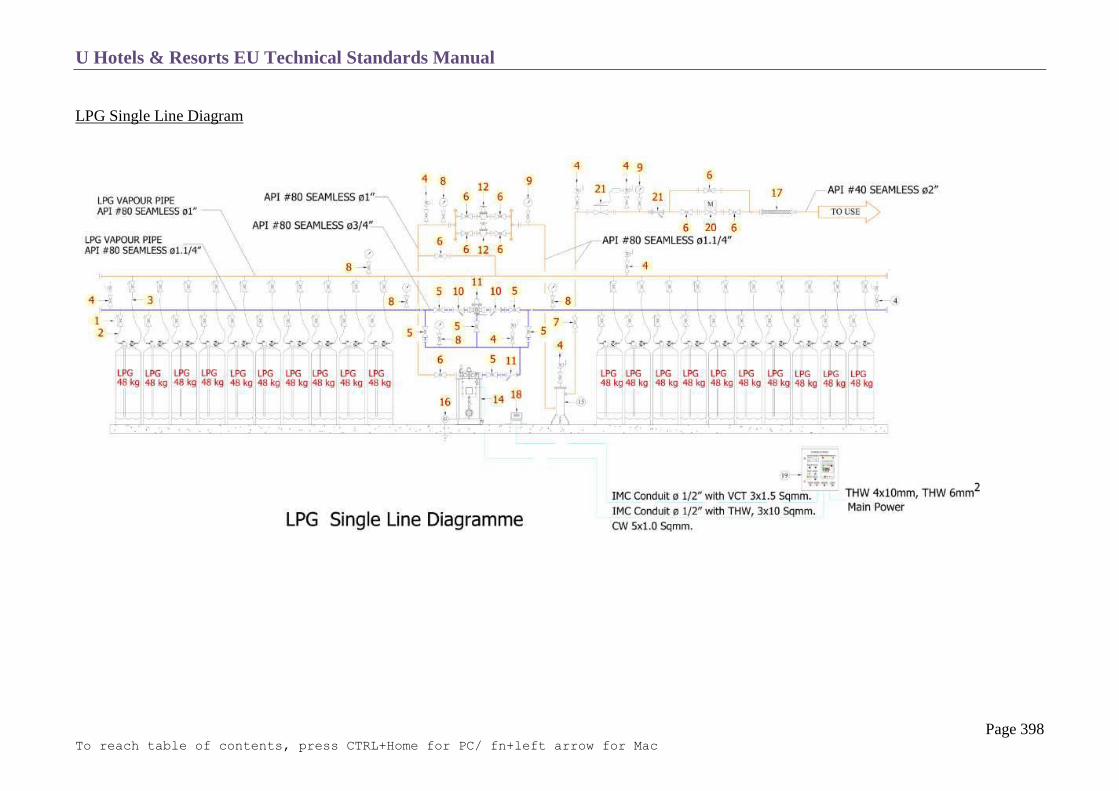
U Hotels & Resorts EU Technical Standards Manual
Page 398 To reach table of contents, press CTRL+Home for PC/ fn+left arrow for Mac
LPG Single Line Diagram
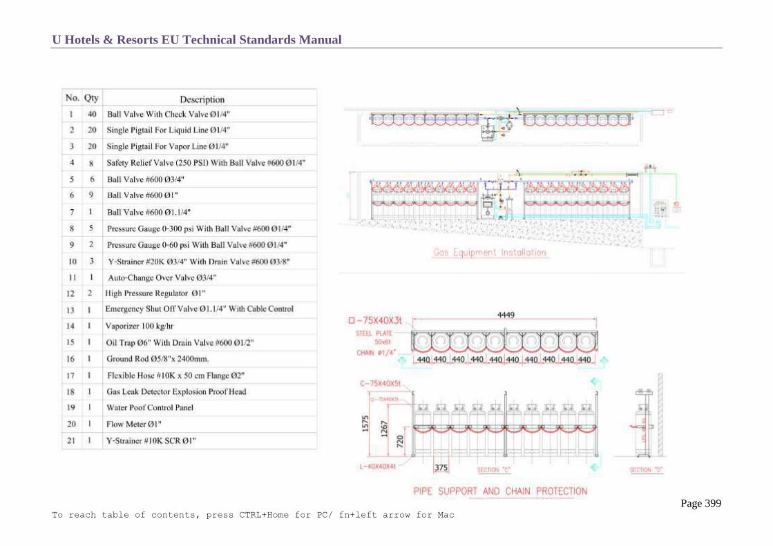
U Hotels & Resorts EU Technical Standards Manual
Page 399 To reach table of contents, press CTRL+Home for PC/ fn+left arrow for Mac

U Hotels & Resorts EU Technical Standards Manual
Page 400 To reach table of contents, press CTRL+Home for PC/ fn+left arrow for Mac
Safety Distance

U Hotels & Resorts EU Technical Standards Manual
Page 401 To reach table of contents, press CTRL+Home for PC/ fn+left arrow for Mac
Safety Distance
Warning Signs

U Hotels & Resorts EU Technical Standards Manual
Page 402 To reach table of contents, press CTRL+Home for PC/ fn+left arrow for Mac
Electrical Wiring for Gas Station

U Hotels & Resorts EU Technical Standards Manual
Page 403 To reach table of contents, press CTRL+Home for PC/ fn+left arrow for Mac

U Hotels & Resorts EU Technical Standards Manual
Page 404 To reach table of contents, press CTRL+Home for PC/ fn+left arrow for Mac
Riser Diagram

U Hotels & Resorts EU Technical Standards Manual
Page 405 To reach table of contents, press CTRL+Home for PC/ fn+left arrow for Mac
SANITARY WARE
Bedroom Equipment (also refer to chapter C3)
General provisions
o all sanitary apparatus will be white or a pale colour
o risers should never be embedded and piping should not be embedded where possible
o visible piping to be reduced as much as possible
o taps and fittings must have a minimum 10-year guarantee and must operate silently. Mechanism is to be of the out-of-water type with 3 /
4 turn ceramic heads including hot/cold colour-coding. Taps, drains, traps, pull chains and anti-splash plugs made of chromed brass of
superior quality (Grohe or similar).
o All drains (especially showers) shall have a capacity at least equivalent to double the supply flow.
all piping will have an equipotential link and will be earthed
Suites may have more luxurious sanitary equipment than the standard bedrooms
Water flows to fixtures
The following shall be considered as minimum flows of cold, hot or mixed water:
Showers = 12 I/min
Toilets = 8 I/min
Washbasins = 12 I/min
Showers:
o acid-resistant enamelled cast iron or built-up with tiles or stone and water proofing
o bottom to incorporate anti-slip treatment as manufactured
o clear depth 10 cm ; recess 3 cm with respect to the adjacent floor
o built-up units have a 3 cm minimum threshold; they can be flush with the bathroom floor if the shower drain is used as a floor drain, in
which case the floor has a 1% slope to drain and is fully waterproof
o removable bell-trap top for cleaning
o the trap must absorb twice the shower flow
o tiles overlap to pan edges with fungicide-treated silicone between the tiling and the shower pan
o single-handle or 3-hole thermostatic or press static mixer valve
o spot-directed towards the vertical wall of shower cabin in order to restrict noise and leave free access to controls
o tempered-glass enclosure and door on non-tiled walls with stainless-steel hardware and supports
U Hotels & Resorts EU Technical Standards Manual
Page 406 To reach table of contents, press CTRL+Home for PC/ fn+left arrow for Mac
WC bowls
o preferably a wall hung bowl, with direct flush and siphon action and made of vitrified porcelain
o cistern fixed to wall and preferably recessed into the wall with direct flushing handle
o fully-closing seat with lid of white or pale colour
o flushing valve prohibited in bedroom floors as being too noisy
o in Islamic countries, provide a hand-held shower next to the toilet if there is no bidet
Wash basins
o bathroom vanity unit with integral bowl of vitrified porcelain, fixed beneath a stone or marble panel. Waterproofing provided by
elastomeric joints with peripheral anti-drip recess
o bowl equipped with overflow, positioned if possible on the opposite side to the mirror
o 3 / 4 turn ceramic double head 3-hole mixer taps
The bathroom vanity unit will comprise of:
a backing strip 10 cm high or panel with full-width mirror,
a drop facing of a minimum height of 25 cm
10 cm high plinths attached to the wall on each side of the bathroom unit with mirrors on top
The top of the vanity unit will be located 85 cm from the finished floor level.
Floor drain
o If a floor drain is to be installed in the bathroom (which is not recommended), the following requirements must be met:
waterproofing over the entire bathroom floor with slope towards the drain
Accessories
o Items to be provided: shower towel rails
double hand towel rails
double toilet paper holders
shaving mirror
tempered glass screens and doors

U Hotels & Resorts EU Technical Standards Manual
Page 407 To reach table of contents, press CTRL+Home for PC/ fn+left arrow for Mac
shower curtain and rod
sanitary bag hook
retractable clothes line
double robe hooks
soap trays
grab bars for shower (as per FFE and interior designer’s lists).
o The finish of all accessories must match that of the sanitary fittings (stainless steel or chrome-plated).
Public Toilets
Obligatory waterproofing, draw-off cock and floor drain
WC bowls (wall hung)

U Hotels & Resorts EU Technical Standards Manual
Page 408 To reach table of contents, press CTRL+Home for PC/ fn+left arrow for Mac
WATER TREATMENT
Treatment of Water for Domestic Use
Cold water for domestic use
o objective
total TH (total hardness) is not important if below approx. 300 ppm. (1)
PH above 7 and below 8.5
bacteriological quality in accordance with criteria specified in 1 above
o treatment equipment
softener to adjust total TH where necessary to a correct level; below 300 ppm and ideally around 100 ppm
dosing pump for injection of alkaline drinkable products (caustic soda or carbonate of soda) to bring pH above 7. If after
injection of the above product a residue to CO2 carbonic gas remains, it will be necessary to install a neutralizer which will
allow the CO2 to be fixed with natural mineral products (Neutralite),
dosing pump with supply of chlorinated solutions (Javel water, HTH, …) making it possible to bacteriological treat the water if
necessary or an approved system of sterilization by ultra violet rays (UVC).
Steam boiler plant
o objectives:
total TH = 0 ppm
pH above or equal to 8.5
o treatment equipment:
softener using ion exchanger resin to bring total TH to 0 ppm
dosing pump coupled with boiler feed water pump for injection of alkaline products, so as to obtain pH above 8.5.
Steam condensation returns are always acid, except in the case of priming (sodium gas mixed with H20). In this case, de-concentration purging is to be
provided to maintain a TAC (total alkali metric content) (2) of around 100˚F maximum.
Closed circuit for technical equipment (heating circuit, chilled water circuit).
o objectives:
total TH = 0 ppm
PH above or equal to 8.5
o treatment equipment
softener to bring down total TH to 0 ppm
U Hotels & Resorts EU Technical Standards Manual
Page 409 To reach table of contents, press CTRL+Home for PC/ fn+left arrow for Mac
mixing pot for alkaline product balls for correction of pH below 8.5.
Cooling-tower circuit
o objectives:
TH = 0 ppm
pH above 8.5 anti-algae
o treatment equipment:
softener to bring TH to 0 ppm
dosing pump for injection of alkaline products in order to bring pH above 8.5
Proportional dosing pump for injection of anti-algae product (Javel water or chlorinated product).
Laundry washing machines
o objectives:
cold water: TH unimportant if TH is below 300 ppm
pH unimportant (within general specified limits)
hot water: TH of 0 to 50 ppm
o treatment equipment:
cold water for rinsing: no special treatment but washing machines are to be connected to cold water
network, upstream of water treatment (hard water)
hot water: water softener if necessary.
Kitchen
o objective:
TH= 0 ppm only for the following items of equipment: coffee machine (espresso and percolator), ice machine, glass washing
machine,
o treatment equipment:
either a special circuit with water softened to TH of 0˚
or individual softener in line with each item of apparatus.
hot water for domestic use
o objective:
TH of 60 to 100 ppm
pH unimportant
o treatment equipment:
softener to bring TH to correct value

U Hotels & Resorts EU Technical Standards Manual
Page 410 To reach table of contents, press CTRL+Home for PC/ fn+left arrow for Mac
dosing pump for film forming treatment with product tank and pulse meter
allowing for dosage in relation to actual water consumption and not in relation to
theoretical throughput as for alkaline treatment.
Protection Against Corrosion
This film-forming treatment is used to protect piping from the corrosive action of certain types of water (in particular soft water), by the deposit
of a protective film. Need for it is established by the analysis mentioned in 1, in conjunction with the treatments mentioned above at the time of
the technical studies for each project.
In the case of steel tube installations, a cold water distribution installation must be protected against corrosion if the water passing through it,
considered at 20˚C, is in one or more of the conditions shown in the following table.
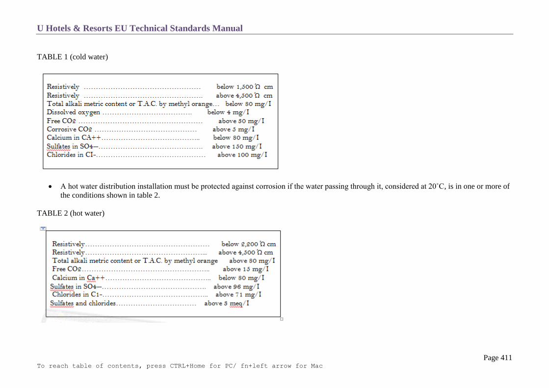
U Hotels & Resorts EU Technical Standards Manual
Page 411 To reach table of contents, press CTRL+Home for PC/ fn+left arrow for Mac
TABLE 1 (cold water)
A hot water distribution installation must be protected against corrosion if the water passing through it, considered at 20˚C, is in one or more of
the conditions shown in table 2.
TABLE 2 (hot water)

U Hotels & Resorts EU Technical Standards Manual
Page 412 To reach table of contents, press CTRL+Home for PC/ fn+left arrow for Mac
Treatment relates to all circuits but the products used are not the same.
o Product to be employed
cold or hot water for domestic use: of foodstuff quality, being made up using silicates, silicone poly-phosphates and zinc
phosphates
water for plant use:
heating plant: nitrites/soda
Chilled water: benzotriazol, nitrites (for effective protection of copper and steel).
o Treatment equipment:
Injection will be carried out using:
a dosage set made up from:
a dosing pump }dimensions to be appropriate for
a product tank }maximum water throughout
a pulse meter }expressed towers,
This being for water for domestic use and cooling towers.
A mixing pot (stainless steel mixing bottle) for heating and chilled water circuits where the volume is below 5 m³
Water takes-off will be installed upstream and downstream of each treatment device, in order to allow for inspection.
In all cases, after analysis and comparison of the different requirements, the idea will be to group together the various treatments in order to
create an efficient central installation.
Swimming Pool Treatment
Treatment equipment:
Dosing pump to allow for introduction of flocculent products (coagulation of small particles by aluminium sulphate), automatic sensors and
dosing pump for chlorinating (sterilization) of water by introduction of Javel water, super-chlorine, calcium hypochlorite, automatic sensors and
dosing pumps:
o for injection of anti-algae product
o for injection of acid product if pH of water is above 8.2
o for injection of alkaline product if pH of water is below 6.9

U Hotels & Resorts EU Technical Standards Manual
Page 413 To reach table of contents, press CTRL+Home for PC/ fn+left arrow for Mac
Pre-filters and closed sand filters, with automatic back-washing, recycling throughput: the volume of water in the swimming pool will be
filtered in a maximum of 4 hours for those sections of the pool more than 1.5m deep, and a maximum of 1.5 hours for the other sections, with
the rate at which water passes through the sand filters not exceeding 50 m/h. For the shallow pools (children’s’), the filtration cycle may not
exceed 0.5 hours.
For Jacuzzis, the recycling rate is at least 10 turnovers per hour; the daily input of new water will be at least equal to 30 litres per bather,
circulation pumps. Automatic (Pool-swipe type) and manual suction sweepers.
The treatment products used must allow the following concentrations to be maintained:
o Free chlorine: 0.4 mg/I < c< 1.4 mg/I for 6.9 < pH < 7.7
o Combined chlorine concentration ≤ 0.6 mg/I
o Bromine: 1 mg/I < c < 2 mg/I for 7.5 < pH < 8.2
Operation of the dosing pumps will thus be controlled by measurement of these concentrations by chlorastat or bromstat, carried out on water
as it leaves the pools.

U Hotels & Resorts EU Technical Standards Manual
Page 414 To reach table of contents, press CTRL+Home for PC/ fn+left arrow for Mac
FIRE PROTECTION
Fire Fighting Resources
Sprinklers
Fire Plugs with Hose and Spout
Fire Pump
Extinguishers
Wet Risers
Dry Risers
Standpipes

U Hotels & Resorts EU Technical Standards Manual
Page 415 To reach table of contents, press CTRL+Home for PC/ fn+left arrow for Mac
FIRE FIGHTING RESOURCES
The resources for firefighting can be:
sprinklers
Hose reels with adjustable nozzle
fixed and mobile extinguishers
wet risers
dry risers
stand pipes
They must comply with current and local regulations with the specifications set out below being minimum specifications.

U Hotels & Resorts EU Technical Standards Manual
Page 416 To reach table of contents, press CTRL+Home for PC/ fn+left arrow for Mac
SPRINKLERS
General Arrangements
U Hotels & Resorts prefers general adoption of the automatic extinguishment system by sprinklers. However if this is not feasible for budgetary
reasons then this Fire Protection system may be omitted in place of alternative systems.
The task of sprinklers is threefold:
monitoring
extinguishment
alarm
The system is made up of four sections:
the sprinkler heads
the networks of pipes made of steel tubes
the monitoring units which locate the sprinkler
the hydraulic equipment.
Sprinkler Heads
The heads can be of various types:
o spraying the water upwards and downwards
o spraying the water downwards (“spray pendent”)
o spraying the water upwards (“spray upright”)
o high temperature in hot zones.
The distance between sprinklers and walls or partitions must not be greater than half the spacing allocated between sprinklers by the regulations
specific to each type of installation, and in no circumstances may it be more than 2.30 m.
They are distributed at a rate of at least 1 every 12 m² with, for bedrooms, 2 sprinkler heads in the bedroom area, 1 in the entrance area and
possibly 1 in the bathroom.
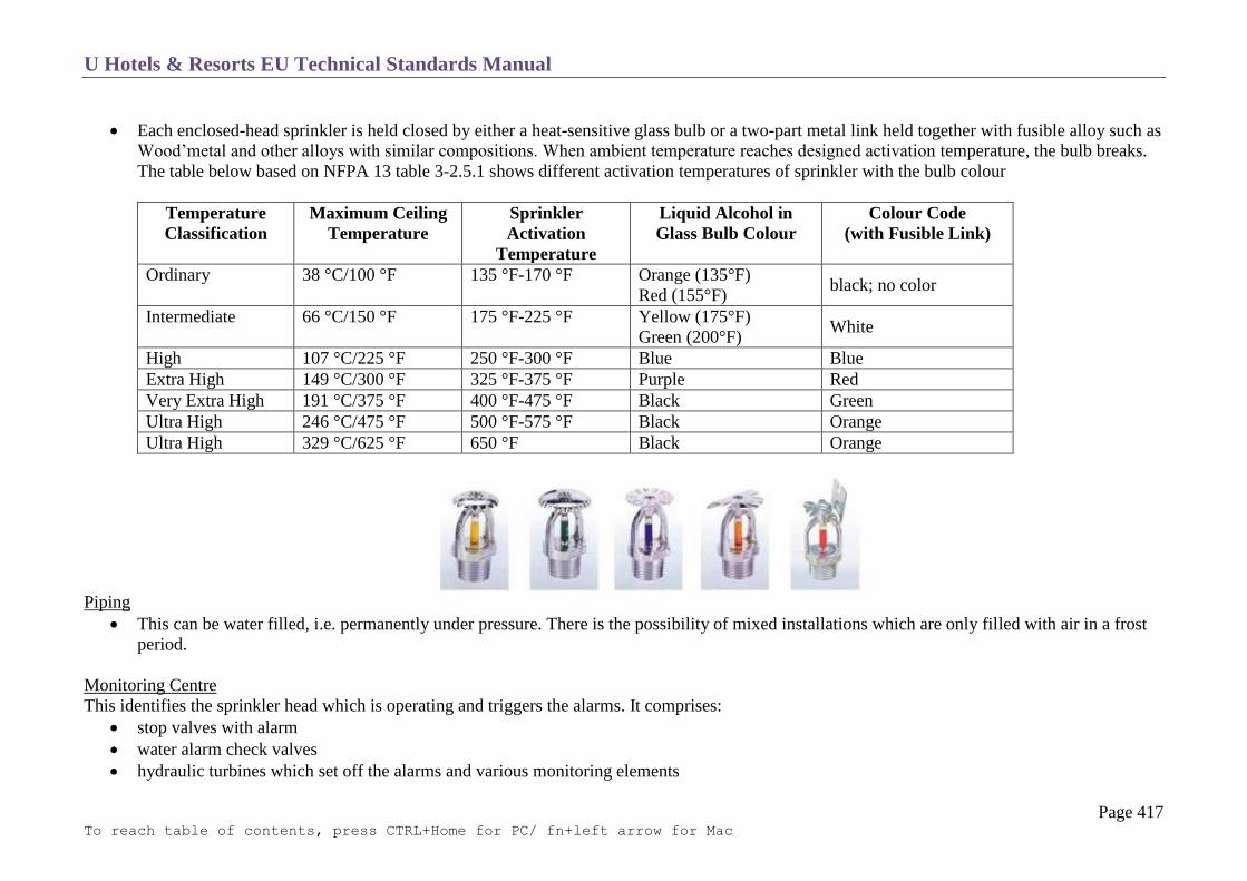
U Hotels & Resorts EU Technical Standards Manual
Page 417 To reach table of contents, press CTRL+Home for PC/ fn+left arrow for Mac
Each enclosed-head sprinkler is held closed by either a heat-sensitive glass bulb or a two-part metal link held together with fusible alloy such as
Wood’metal and other alloys with similar compositions. When ambient temperature reaches designed activation temperature, the bulb breaks.
The table below based on NFPA 13 table 3-2.5.1 shows different activation temperatures of sprinkler with the bulb colour
Temperature
Classification
Maximum Ceiling
Temperature
Sprinkler
Activation
Temperature
Liquid Alcohol in
Glass Bulb Colour
Colour Code
(with Fusible Link)
Ordinary 38 °C/100 °F 135 °F-170 °F Orange (135°F)
Red (155°F) black; no color
Intermediate 66 °C/150 °F 175 °F-225 °F Yellow (175°F)
Green (200°F) White
High 107 °C/225 °F 250 °F-300 °F Blue Blue
Extra High 149 °C/300 °F 325 °F-375 °F Purple Red
Very Extra High 191 °C/375 °F 400 °F-475 °F Black Green
Ultra High 246 °C/475 °F 500 °F-575 °F Black Orange
Ultra High 329 °C/625 °F 650 °F Black Orange
Piping
This can be water filled, i.e. permanently under pressure. There is the possibility of mixed installations which are only filled with air in a frost
period.
Monitoring Centre
This identifies the sprinkler head which is operating and triggers the alarms. It comprises:
stop valves with alarm
water alarm check valves
hydraulic turbines which set off the alarms and various monitoring elements

U Hotels & Resorts EU Technical Standards Manual
Page 418 To reach table of contents, press CTRL+Home for PC/ fn+left arrow for Mac
1. Stop Valve 2. Valve Monitor 3. Alarm Valve 4. Sprinkler Head 5. Alarm Test Valve 6. Alarm Bell (Gong) 7. Pressure Switch 8. Jockey Pump 9. Flow Switch
This centre transmits the alarms to the control room and the telephone exchange.
Hydraulic Equipment
This involves:
a pressure booster plus motor driven pump
an air compressor
a pressure tank
water reserves, the capacities of which will be specified by the criteria of insurance companies. Whatever the circumstance, they will not be less
than 35 m³.
Typical Sprinkler System Diagram

U Hotels & Resorts EU Technical Standards Manual
Page 419 To reach table of contents, press CTRL+Home for PC/ fn+left arrow for Mac
FIRE PLUGS WITH HOSE AND SPOUT
These must be placed inside so that the entire area of the premises can be effectively reached. In premises with particular risks, all points must
come within the range of at least two nozzles. Preferably they will be placed as close as possible to the outside of the premises to be protected,
in common passageways.
They must be encased in unlocked cabinets which do not project into the passageways.
They must have a semi-rigid pipe at least 20 m long without any intermediate joint with a check valve and there must be brackets for
supplementary equipment such as fire buckets and fire axes.
The minimum operating pressure must not be below 2.5 bar (36 p.s.i.); the supply of water must be via pressurized water piping fed from the
public mains. Preferably, the distribution network should be constructed in “meshed” form, with lower and upper ring.

U Hotels & Resorts EU Technical Standards Manual
Page 420 To reach table of contents, press CTRL+Home for PC/ fn+left arrow for Mac
FIRE PUMPS
Part of fire sprinkler system’s water supply
The pump is connected to the public water supply piping or use a static water source such as tank, reservoir or lake
Provide water flow at a higher pressure to the sprinkler system and hose standpipes
A jockey pump is a small pump connected to a fire system to maintain pressure in a fire protection piping system

U Hotels & Resorts EU Technical Standards Manual
Page 421 To reach table of contents, press CTRL+Home for PC/ fn+left arrow for Mac
EXTINGUISHERS
Fixed Extinguishers
Fixed extinguishment systems with automatic triggering are specified for the following facilities:
kitchen hoods (Co2)
boiler burners (powder extinguishers)
main electrical equipment rooms (Inergen).
These systems have a separate alarm which is linked to the fire detection centre.
Mobile Extinguishers
Portable or mobile extinguishers are:
o atomized water in bedrooms, offices, linen stores
o Co2 in services rooms and premises with electrical apparatus
o 50 kg polyvalent powder on wheeled frames in parking areas and plant rooms.
They are distributed in clear areas, easily visible and accessible and protected from major temperature changes.
Where placed in areas with public access, they are housed in wall cupboards or recesses designed to blend with the decor of the building.

U Hotels & Resorts EU Technical Standards Manual
Page 422 To reach table of contents, press CTRL+Home for PC/ fn+left arrow for Mac
WET RISERS
These columns are associated with the fireplugs with hose and spout.
The fire outlets for these columns must be located in stairwells and staircases.
The supply unit for each column (feed tank, supercharger and pump) must ensure an hourly throughput of 60 m³ under static pressure between
4.5 and 8.5 bars (65 and 125 p.s.i.).
It must be possible to refill the columns from two 65 mm apertures equipped with valves and located at the fire department access level less
than 60 m away from a standpipe or hydrant.
DRY RISERS
The supply connections for dry risers must be easily accessible to the fire department on the wall which is closest to the standpipes or fire
hydrants. The distance between these connections and the hydrants must not be more than 60 meters.
The outlets must be located in the stairwells or staircases. They must be of a type which is suitable for the fire department equipment and must
have a hydrant key.

U Hotels & Resorts EU Technical Standards Manual
Page 423 To reach table of contents, press CTRL+Home for PC/ fn+left arrow for Mac
STANDPIPES
If the public water plugs are too far away, or if they provide inadequate throughput, there can be a requirement to install private standard
standpipes for the hotel.
They must be painted to comply with local standards.
They can be substituted by water supplies which are easy to use: flowing water, tanks, and swimming pools.
Arrangements will be made so that any water overflowing into any storey at the time of a fire can be drained off and will not invade the
staircases, lifts and hoist.

U Hotels & Resorts EU Technical Standards Manual
Page 424 To reach table of contents, press CTRL+Home for PC/ fn+left arrow for Mac
FIRE DETECTION
General Notes
Detection Principle
Detectors
Alarm Push Buttons
Smoke Outlet Control Push Buttons
Communications Centre
Electrical Supply
Fault Warning
Alarm Warning
Automatic Extinguishment Control
Fire Suppression System
Automatic Control System

U Hotels & Resorts EU Technical Standards Manual
Page 425 To reach table of contents, press CTRL+Home for PC/ fn+left arrow for Mac
GENERAL NOTES
The purpose of the fire detection installation is to detect fires as soon as they start, to give the alarm and to trigger the automatic controls.
The zones to be protected will cover all public areas, service areas and extraction conduits from such premises.
The detection system will automatically control mechanical and natural smoke removal from the zone in question and all the automatic controls
described hereafter.
DETECTION PRINCIPLE
Fire detection equipment is generally installed throughout the premises, with the exception of bathrooms and toilets.
They system is of the analogue type and allows each detector to be addressed. However, all public areas could be of conventional system.
The control centre, detectors and pushbuttons form a homogeneous package, with continuous dialogue being maintained between the various
elements.
The sensors continuously transmit readings to the control centre which compares them with the programmed figures.
The control centre can then decide to give the detector alarm status or to record it as faulty.

U Hotels & Resorts EU Technical Standards Manual
Page 426 To reach table of contents, press CTRL+Home for PC/ fn+left arrow for Mac
DETECTORS
The detectors will be tailored to the premises to be monitored, in particular:
o Preference will be given to use of smoke detectors in all premises such as passageways, conference halls, restaurants and ventilation
ducts (blown air and recovery).
o Thermo-velocimetric detectors in service rooms, car parks, storage rooms and kitchens.
o Thermostatic detectors in workshops.
The area monitored by a detector will not be more than 50 m² in rooms. In passageways, maximum spacing will be 20 meters.
The entire system will be divided into zones, in which case an individual zone will not have more than 25 detectors, or one floor or part of one
floor of bedrooms.
There will be a smoke detector at the entrance to each bedroom, even if it is protected by sprinklers.
They will operate on 24V direct current.
Each detector controls an individual operating light indicator, incorporated into its base.
Detectors must remain in alarm mode until it is cancelled by manual operation at the detection control centre; at such time they must
automatically revert to the monitoring mode.
Smoke detector over the bed in guestroom will have a sounder base with minimum 95 decibels at the pillow.

U Hotels & Resorts EU Technical Standards Manual
Page 427 To reach table of contents, press CTRL+Home for PC/ fn+left arrow for Mac
ALARM PUSH BUTTONS
On each floor and close to each staircase there will be a push button or some other alarm device, in accordance with local regulations.
Push buttons will be in red boxes of the fixed glass type. Breaking the glass sends the alarm warning to the control centre.
They are of the flush fit type.
They are equipped with a red-coloured face frame and a fire symbol indicating their purpose.
SMOKE OUTLET CONTROL PUSH BUTTONS
These push buttons may only be used by firemen or the hotel security team and are used for manually opening the smoke vents.
They have the same characteristics as the alarm push buttons; their use is clearly indicated so that they cannot be confused with the others.
COMMUNICATIONS CENTRE
This is located in the fire safety and plant control room or engineering offices, with repeaters in the security office and in the reception/guest
service centre.
The electronic equipment of the control centre must make it possible to:
o Process rapidly a considerable number of possible information items (alarm, fault, monitoring etc) whilst observing degrees of urgency
between the relevant signals.
o Transmit such information easily by remote means.
o Maintain continuous monitoring of:
the electrical supply network
the condition of batteries
all automatic controls
detection networks
monitoring lines
It is equipped with a specific screen, or a glazed panel which allows the signals to be displayed.

U Hotels & Resorts EU Technical Standards Manual
Page 428 To reach table of contents, press CTRL+Home for PC/ fn+left arrow for Mac
Optical and sound signalling of faults and alarms must not be confused with each other.
The control centre must automatically display on a separate screen all occurrences in the installation in chronological order.
Identification of detectors and push buttons is carried out automatically on the screen. A sound signal gives automatic warning of the
occurrence of any event.
The control centre is equipped with a printer which enables a detailed listing to be produced of events of the past week, with corresponding
dates and times.
It is also equipped with a remote transmission facility capable of calling automatically and in sequence programmed telephone numbers in the
event of an alarm.

U Hotels & Resorts EU Technical Standards Manual
Page 429 To reach table of contents, press CTRL+Home for PC/ fn+left arrow for Mac
ELECTRICAL SUPPLY
The control centre is supplied from the electricity main supply and includes a battery charger and set of batteries.
The batteries are cut in and shut off automatically when the normal power supply breaks down or is re-established.
The battery capacity is sufficient to allow emergency operation for 12 hours minimum.
FAULT WARNING
All defects in the installation must be automatically notified to the communications centre by optical and sound signal.
The sound signal can be halted without interrupting operation of the luminous optic signal.
The optical fault warning must be maintained until the defect disappears or is rectified.
ALARM WARNING
The alarm warning is carried out:
o By sound and visual means in the communications centre and on the repeater panels.
o By alarm sirens and visual signs in passageways and rooms.
The alarm in bedrooms (signal for evacuation) will take two forms:
o By broadcasting a message from reception using public address equipment.
o By buzzers and blinkers placed in each bedroom and passageway, controlled automatically via the fire detection system and with a time
limit and facility for cancellation from the fire safety and plant control centre.
These alarm system are connected to the emergency power supply described in T7 – Electrical Supply.

U Hotels & Resorts EU Technical Standards Manual
Page 430 To reach table of contents, press CTRL+Home for PC/ fn+left arrow for Mac
FIRE ALARM SYSTEM DIAGRAMME

U Hotels & Resorts EU Technical Standards Manual
Page 431 To reach table of contents, press CTRL+Home for PC/ fn+left arrow for Mac

U Hotels & Resorts EU Technical Standards Manual
Page 432 To reach table of contents, press CTRL+Home for PC/ fn+left arrow for Mac

U Hotels & Resorts EU Technical Standards Manual
Page 433 To reach table of contents, press CTRL+Home for PC/ fn+left arrow for Mac

U Hotels & Resorts EU Technical Standards Manual
Page 434 To reach table of contents, press CTRL+Home for PC/ fn+left arrow for Mac
AUTOMATIC EXTINGUISHMENT CONTROL
The high voltage/low voltage room and the generating set room (Inergen), the lift machinery rooms (powder), the kitchen hoods (CO2) and the
boiler burners (powder) are equipped with appropriate automatic fire extinguishment systems.
These systems are controlled:
o Automatically via the fire detection installation: automatic control with time limit.
o Manually, from an electric push button placed under glass and linked directly to the communications centre: manual control with time
limit.
FIRE SUPPRESSION SYSTEM
Most fires in hotels or restaurants ignite in the kitchens by deep-fat fryer, wok and grill therefore this system is compulsory for any main
kitchen hood.
Cooking equipment currently manufactured uses more efficient burners, resulting in much higher heating rates. More cooking is done with
vegetable oil instead of animal fats. Vegetable oils have a much higher auto ignition temperature. Fryers are now made with improved
insulation that slows the cooling rate, but which also increases the risk of a re-flash in the event of fire.
Fire suppression systems are custom fit and require a dedicated consultant to specifically tailor them.
o Kitchen suppression systems are actuated by a fusible links located above the cooking appliances.
o The links melt during a fire, causing a cartridge to fire propelling gas into the liquid agent tank.
o The distribution piping system carries the agent to nozzles located above the cooking appliances, in the plenum above the filters, and in
the duct above the plenum.
U Hotels & Resorts recommends internationally approved products like;
o Ansul R-102 ( www.ansul.com )
o Range Guard UL 300 ( www.rangeguard.com )
o Pyrochem ( www.pyrochem.com )

U Hotels & Resorts EU Technical Standards Manual
Page 435 To reach table of contents, press CTRL+Home for PC/ fn+left arrow for Mac

U Hotels & Resorts EU Technical Standards Manual
Page 436 To reach table of contents, press CTRL+Home for PC/ fn+left arrow for Mac
U Hotels & Resorts EU Technical Standards Manual
Page 437 To reach table of contents, press CTRL+Home for PC/ fn+left arrow for Mac
AUTOMATIC CONTROL SYSTEM
The communications centre carries out programming and control of the following automatic control systems, tailored in accordance with current and
local regulations:
Initiation of evacuation signal in rooms of the section concerned, including passageways and rooms holding more than 20 people.
Automatic closing of fire cut-off doors which are normally kept open continuously by magnetic catches.
Opening smoke extraction outlets.
Closing the gas shut-off valve which supplies the heating plant and the kitchen.
Lift non-stops system.
Reset to zero lifts which are automatically brought down to the hotel entrance level.
Halting ventilation fans with automatic restarting after the end of the fire alarm.
Unlocking of external doors in emergency staircases leading outside.
Automatic control of mechanical smoke removal system (blowing + extraction).
Automatically controlled fire dampers.
Power supply and control: power supply to automatic control systems goes via the detection centre. All automatic control systems of the positive safety
type, i.e. in the event of supply or control cable being cut, the systems served react as though there were a fire alarm.

U Hotels & Resorts EU Technical Standards Manual
Page 438 To reach table of contents, press CTRL+Home for PC/ fn+left arrow for Mac
VENTILATION – AIR CONDITIONING
General Notes
Treatment of Rooms
Heat Production
Cold Production
Distribution Network and Terminal Equipment
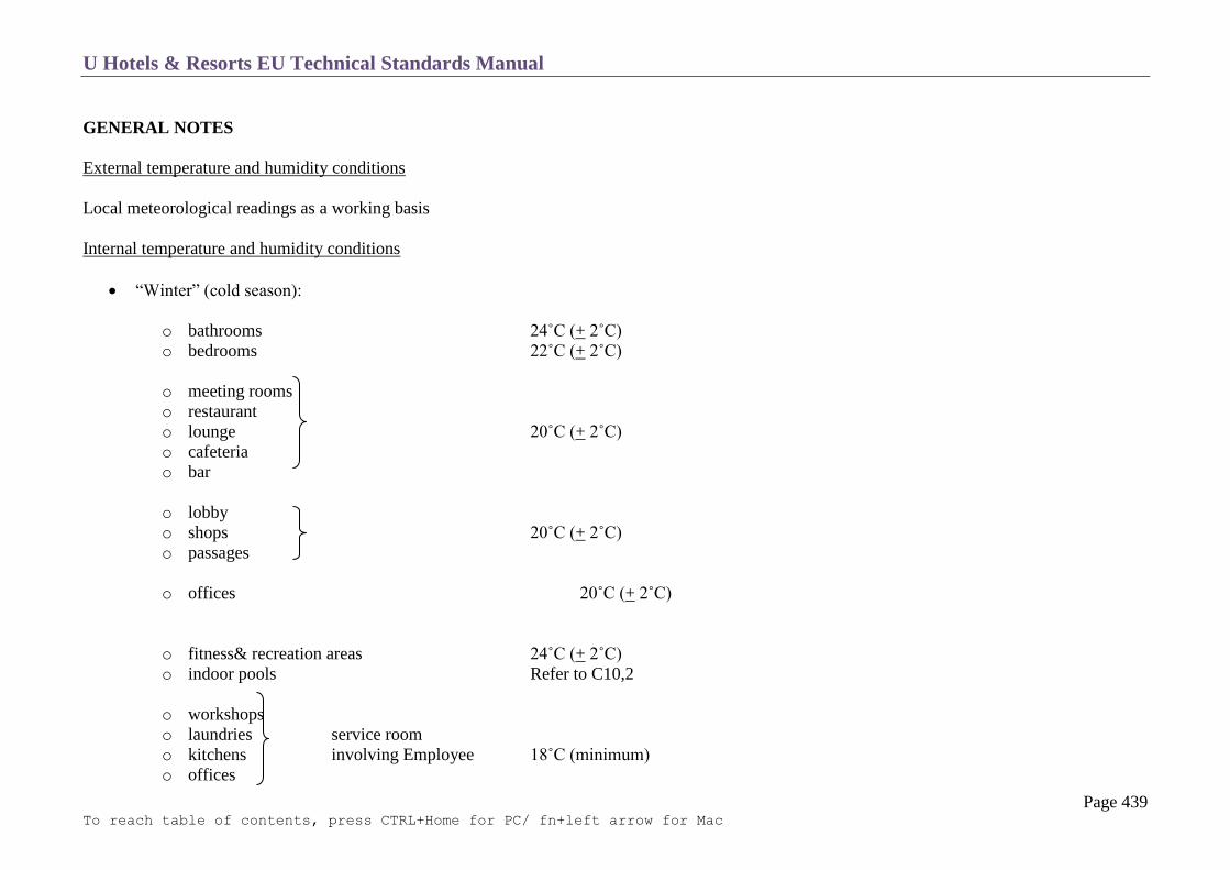
U Hotels & Resorts EU Technical Standards Manual
Page 439 To reach table of contents, press CTRL+Home for PC/ fn+left arrow for Mac
GENERAL NOTES
External temperature and humidity conditions
Local meteorological readings as a working basis
Internal temperature and humidity conditions
“Winter” (cold season):
o bathrooms 24˚C (+ 2˚C)
o bedrooms 22˚C (+ 2˚C)
o meeting rooms
o restaurant
o lounge 20˚C (+ 2˚C)
o cafeteria
o bar
o lobby
o shops 20˚C (+ 2˚C)
o passages
o offices 20˚C (+ 2˚C)
o fitness& recreation areas 24˚C (+ 2˚C)
o indoor pools Refer to C10,2
o workshops
o laundries service room
o kitchens involving Employee 18˚C (minimum)
o offices

U Hotels & Resorts EU Technical Standards Manual
Page 440 To reach table of contents, press CTRL+Home for PC/ fn+left arrow for Mac
o linen store
o various stores rooms without employees 14˚C
Relative humidity ≥ 40%
“Summer” (hot season)
Air conditioned or not
Temperatures where premises are air-conditioned:
air conditioned premise(when Ext. T > 25˚C)
o internal temperature in ˚C = 20˚ + 0.32 × (external temperature -20˚), with an absolute maximum of 25˚C in all situations with reference
relative humidity of 50%. Internal humidity: between 30 and 60%
o calculation of all installations (more specifically conference rooms and banqueting rooms) will take into consideration the unoccupied
calorific loading of such installations, in particular lighting and those due to occupants, at a rate of 4 persons per 3 m² in a cocktail
configuration for the conference rooms.
Kitchen
o internal temperature in ˚C = 20˚ + 0.40 × ( external temperature -25˚)
o internal humidity < 60%
Laundry
o internal temperature in ˚C = 20˚ + 0.40 × ( external temperature -25˚) taking into
account heat released from machines humidity of < 75 %
Wine Cellar: 16˚C (outside cold room)
Ventilation rate
Bedrooms and public rooms:
o bedroom
fresh air: 2 volumes per hour, minimum 120 m³/h
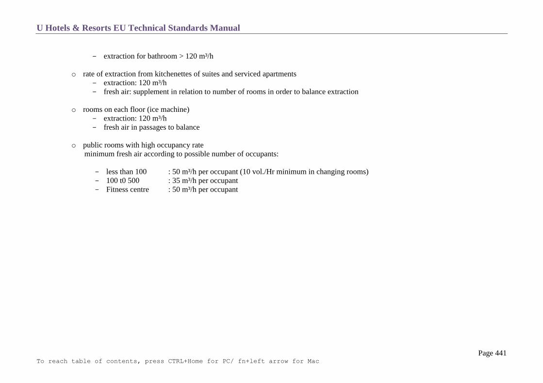
U Hotels & Resorts EU Technical Standards Manual
Page 441 To reach table of contents, press CTRL+Home for PC/ fn+left arrow for Mac
extraction for bathroom > 120 m³/h
o rate of extraction from kitchenettes of suites and serviced apartments
extraction: 120 m³/h
fresh air: supplement in relation to number of rooms in order to balance extraction
o rooms on each floor (ice machine)
extraction: 120 m³/h
fresh air in passages to balance
o public rooms with high occupancy rate
minimum fresh air according to possible number of occupants:
less than 100 : 50 m³/h per occupant (10 vol./Hr minimum in changing rooms)
100 t0 500 : 35 m³/h per occupant
Fitness centre : 50 m³/h per occupant

U Hotels & Resorts EU Technical Standards Manual
Page 442 To reach table of contents, press CTRL+Home for PC/ fn+left arrow for Mac
Service Rooms:
Fresh air
(in volume/hour)
Extraction
(in volume/hour)
kitchen
30 minus air transferred
from restaurant
34
Transfer between the restaurant and the kitchen will arise by natural overpressure via a duct which has acoustic lining.
It is essential that all the kitchen and annex facilities are placed at lower pressure compared with the surrounding rooms.
Special attention will be paid to the design of the hood of the cooking area.
laundry and dry cleaning
30 35
washing up
20 25
glass washing (per unit) 4,000 m³/h
Employee and other stores 6 6
workshops 10 10
boiler plant (with
modulation according to
output and regulation)
40 20
refrigerating sets 15 20
air units 10 15
transformer set 15 18
generating set 20 according to set
lift machinery 15 15
telephone
exchange/PABX
15 10
offices 3 3

U Hotels & Resorts EU Technical Standards Manual
Page 443 To reach table of contents, press CTRL+Home for PC/ fn+left arrow for Mac
NB: for technical and service rooms, indicated ventilation rates can be reduced if the rooms are air-conditioned.
TREATMENT OF ROOMS
Bedrooms (according to location)
Distribution of pre-treated fresh air with bedrooms.
Fan-coil unit linked through loops to two different networks, one permanently conveying cold water and the other conveying hot water.
Individual regulation by environment thermostat.
Control for fan (3 speeds + Off position).
An automatic electric switch makes it possible to stop the fan-coil fan and close off the cooled water valves if the windows or the balcony doors
are opened.
Restaurants, Conference and Meeting Rooms
Individual 4 tube treatment unit per room.
Low pressure blowing system with distribution of treated air and regulation per rooms.
Partial recycling of air.
Each portion of the multipurpose hall and each meeting room must have its own unit and be regulated in an independent manner.
Air extracted from public rooms may be recovered to supply the technical rooms and in certain cases service rooms.
Bars
One hundred per cent fresh air low pressure individual unit.
Kitchen, Laundry
Individual treatment unit per room; low pressure blowing unit with distribution of treated air and regulation per room. Air transferred from
restaurant for kitchen.

U Hotels & Resorts EU Technical Standards Manual
Page 444 To reach table of contents, press CTRL+Home for PC/ fn+left arrow for Mac
HEAT PRODUCTION
Administration and Service Offices
Pre-treated fresh air + fan-coil
Other Service Rooms
Low pressure centralized treatment. A static heating circuit will cater for:
occasional heat requirements
heating of passages
heating of glazed zones in order to prevent condensation
Garages
Ventilation will be designed in such a way so as not to exceed the maximum carbon oxides concentration threshold.

U Hotels & Resorts EU Technical Standards Manual
Page 445 To reach table of contents, press CTRL+Home for PC/ fn+left arrow for Mac
COLD PRODUCTION
Chilled Water Production Sets
Type of chilled water production sets:
o Unit discharge capacity < 600 KW: piston set
o Unit discharge capacity > 600 KW: centrifuge or worm set
Coolant fluid: The system will utilize fluids, the ozone depletion factor of which is the lowest available on the market such as HFCs (e.g. R125,
R134 a…mixtures). CFCs and HCFCs are forbidden.
As an indication, the absolute minimum nominal capacity is minus 1000 calories/sec/room, to be multiplied by 2 for the installed capacity.
NB: 1 KCAL = 3.97 BTU = 4186 J = 4.18 KW × S
Number of chilled water generators:
o total discharge capacity < 3,000 KW N = 2
o total discharge capacity > 3,000 KW N = 3
o in addition to the previous sets, there will be a supplementary piston set of capacity equal to 30% of the unit capacity of the main sets
Control equipment:
o thermostatic release valve
o step-by control with minimal and maximum contact thermometer, dial thermometer for cold water
o antifreeze protection thermostat
o high and low pressure safety device
o oil pressure monitor
A cabinet containing the equipment with operating and breakdown indicator, manometer, relays, fuses, cables, etc.
A starter with autotransformer system enabling the start-up intensity to be restricted to 3 times the operation intensity.
Throughput monitors for chilled water circuits and condenser cooling water circuits, which automatically stop the compressor if there is no
circulation.
Sound breakers: these units will be placed on anti-vibration bases with flexible collars inserted for connections to hydraulic networks.
In general, sets will provide pre-heating of hot domestic water supply by recover of heat with double condensers.

U Hotels & Resorts EU Technical Standards Manual
Page 446 To reach table of contents, press CTRL+Home for PC/ fn+left arrow for Mac
Air Cooling Units (cooling towers)
Number of items of apparatus: 2 as minimum each having 70% capacity.
Preferably water towers (except in countries where water is scare or expensive, where air condensers will be provided).
o Equipment to be provided:
o a stainless steel basin will be equipped with a salinometer controlling an electromagnetic valve for reducing concentration of mineral
salts and a supply cock with float
o antifreeze safety device
o drains
Location takes into account visual nuisances due to steam and mist and sound nuisances. If there is risk of noise nuisance, install sound traps.
In all sites exposed to dust (for example from sand winds) and in all cases for cooling of heat pumps circuits, provide “closed” air cooling
systems in which the cooled water is not in direct contact with the atmosphere.
o Water supply:
metering
treatment to obtain 0 total hardness and pH> 8.5
treatment against bacteria
algaecide treatment
pre-heating of domestic hot water
All components will be specially protected against corrosion and will be fireproofed.
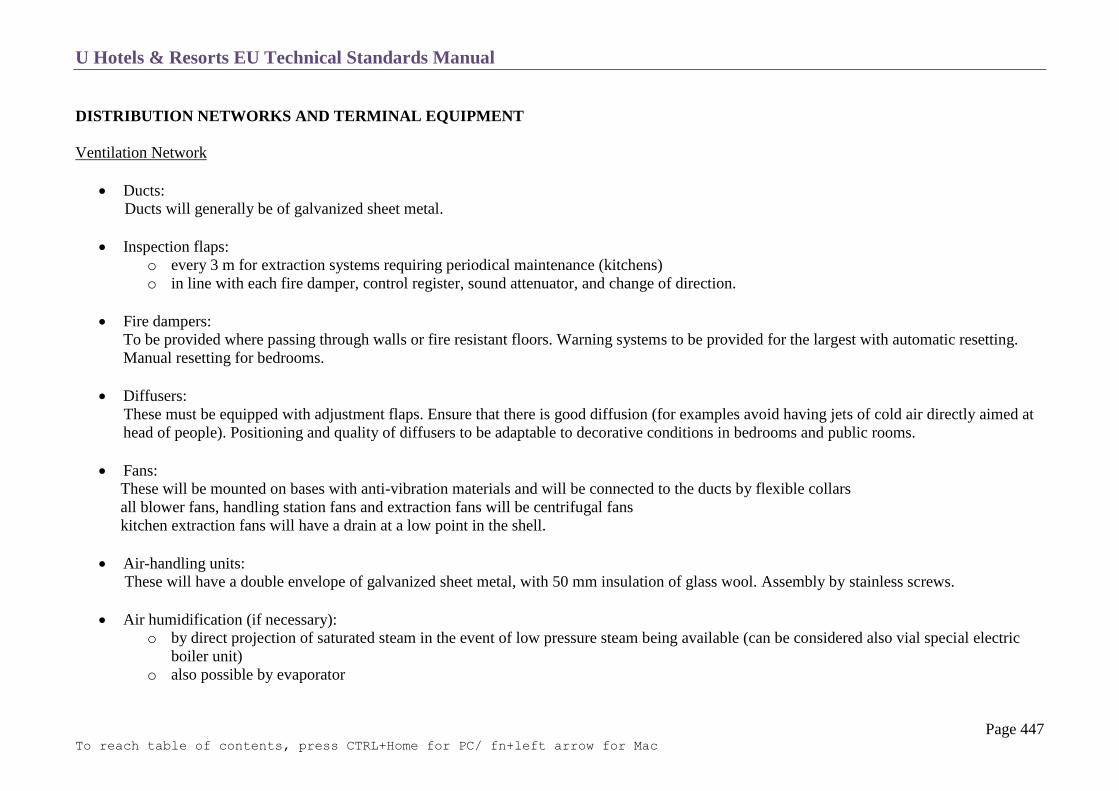
U Hotels & Resorts EU Technical Standards Manual
Page 447 To reach table of contents, press CTRL+Home for PC/ fn+left arrow for Mac
DISTRIBUTION NETWORKS AND TERMINAL EQUIPMENT
Ventilation Network
Ducts:
Ducts will generally be of galvanized sheet metal.
Inspection flaps:
o every 3 m for extraction systems requiring periodical maintenance (kitchens)
o in line with each fire damper, control register, sound attenuator, and change of direction.
Fire dampers:
To be provided where passing through walls or fire resistant floors. Warning systems to be provided for the largest with automatic resetting. Manual resetting for bedrooms.
Diffusers:
These must be equipped with adjustment flaps. Ensure that there is good diffusion (for examples avoid having jets of cold air directly aimed at head of people). Positioning and quality of diffusers to be adaptable to decorative conditions in bedrooms and public rooms.
Fans:
These will be mounted on bases with anti-vibration materials and will be connected to the ducts by flexible collars
all blower fans, handling station fans and extraction fans will be centrifugal fans
kitchen extraction fans will have a drain at a low point in the shell.
Air-handling units:
These will have a double envelope of galvanized sheet metal, with 50 mm insulation of glass wool. Assembly by stainless screws.
Air humidification (if necessary):
o by direct projection of saturated steam in the event of low pressure steam being available (can be considered also vial special electric
boiler unit)
o also possible by evaporator

U Hotels & Resorts EU Technical Standards Manual
Page 448 To reach table of contents, press CTRL+Home for PC/ fn+left arrow for Mac
o overflow and drain pipe to be provided in tanks. The water supply quality will comply with 0 total hardness and pH > 8.5. It will be
treated against the development of bacteria.
Filtration:
o 2 sets of filters
o the first filter to have interchangeable front elements (efficiency of 90% in ASHRAE gravimetric test)
o the second will be a bag filter

U Hotels & Resorts EU Technical Standards Manual
Page 449 To reach table of contents, press CTRL+Home for PC/ fn+left arrow for Mac
Water Networks
Piping:
See requirements for sanitary plumbing networks. PVC piping may also be used. Preference may be given to the umbrella system.
Valves:
To be installed:
o at all connections to main piping
o at all pumps and generally all items of equipment
o for all tanks
Pumps:
One pump always to be provided as a stand-by.
Air bleed points and sludge drains:
o air bleed points to be created at high points on covers, with drain valve
o at low points of columns: sludge collection pots with drain cocks
o main boiler plant collectors to be equipped with drains
Paint:
Paintwork to be in standard colours for piping with signs for fluid movement direction.
Insulated piping will be identified by rings of appropriate colour, made of adhesive strip or painted on and placed every meter on the running
portion and at the location of any obstacles such as valve, cocks, passages through walls or floors and changes in direction.
Indication of direction of circulation of fluids to be given by arrows, particularly where there are obstacles (essential for valves and stopcocks).
Literal indications as to the exact nature of the fluid are to be given by tags or direct inscriptions.
U Hotels & Resorts EU Technical Standards Manual
Page 450 To reach table of contents, press CTRL+Home for PC/ fn+left arrow for Mac
Insulation
Insulation to be provided for hot water and chilled water and steam, including for valves, tanks, and pump bodies.
The insulation is to be resistant to impact.
All treated air ducts will be insulated or double lined. Recycled air ducts passing through non-air conditioned rooms and intakes of external air
in cold climates must be insulated.
Insulation must comply with local fire regulations, and must be of a type which withstands moisture. A continuous vapour barrier is
compulsory for all-cold air ducts and chilled water pipes.
Preference may be given to the system of pre-insulated piping.
Fan-Coil Units
Fan-coils will comprise a galvanized section frame to which will be fixed:
the heat exchange batteries (one for heating, the other for cooling)
a silent operation outward flow turbine with three blowing speeds (below 35 dB (LnAT) in bedroom for speeds3, 32 dB for speed 2, 30 dB for
speed 1)
an insulated tank for condensation recovery, with drainage to a recovery network (plastic with adequate slope)
a dry-operating regeneration type filter
the batteries will be of copper tubing with aluminium fins
The equipment will consist of two versions:
horizontal presentation without body for installation in false ceiling (bedrooms)
vertical presentation with body for wall mounting
4 position control box (stop + 3 speeds).
acoustics: See section C-21 Sound Insulation.
Economic cycle A: in countries of groups 1 and 2, air conditioning systems using recycled air will be investigated in order to operate on an
economic cycle.
This cycle uses the possibilities of free cooling in the intermediate season, taking in up to 100% of direct external air.

U Hotels & Resorts EU Technical Standards Manual
Page 451 To reach table of contents, press CTRL+Home for PC/ fn+left arrow for Mac
Control System
Advanced control systems for VRV indoor units

U Hotels & Resorts EU Technical Standards Manual
Page 452 To reach table of contents, press CTRL+Home for PC/ fn+left arrow for Mac
Centralised control systems for VRV indoor units
Up to 64 groups of indoor units (128 units) can be centrally controlled
Optional controllers for centralised control can be combined freely and a system can be designed in accordance with building scale and
purpose.
System integration with various air-conditioning peripheral equipment, such as a Heat Ventilator, is easily made.
Wiring can be run up to a total length of 2 km and adapt easily to large-scale system expansion.

U Hotels & Resorts EU Technical Standards Manual
Page 453 To reach table of contents, press CTRL+Home for PC/ fn+left arrow for Mac
ELECTRICITY
General Notes
Transformation – High Voltage Equipment
General Low Voltage Panel
Cabinets
Distribution
Safety Lighting
Emergency Generating Sets
Lightning Protection

U Hotels & Resorts EU Technical Standards Manual
Page 454 To reach table of contents, press CTRL+Home for PC/ fn+left arrow for Mac
GENERAL NOTES
The building will be supplied via a transformer station which will contain the transformers, each of which supplies a set of general low voltage
bars.
Emergency power supplied by the generating set will be input at the low voltage bars set.
Links between the generating set and the general low voltage panel must be as short as possible.
Installations must be designed to operate on a sector basis, in order to guarantee vertical and horizontal selectivity for medium and low voltage
with default to ground or short circuit.
This means that protection devices are calibrated and have the necessary cut-off powers to ensure that only the item of equipment located
directly upstream of the fault is triggered.
As a standard the neutral will be grounded.
All protections in the general panel and in the secondary panels will be by means of circuit breakers, including protection for secondary outlets
provided by modular circuit breakers.
Voltage drops in the networks must not exceed the following limit between the low voltage terminals of the transformer and the remotest point
in the installation:
o 2% for lighting and sockets
o 3% for power.
All electrical equipment will be designed to take into account the climatic conditions of the site.
For any tall building (the height of which is more than 28 m), 2 low voltage panels must be provided, supplying the safety installations. If one
of these panels loses current, an automatic converter switches the supply to the other panel. A 2-hour fire retardant bulkhead must separate the
two panels from each other.
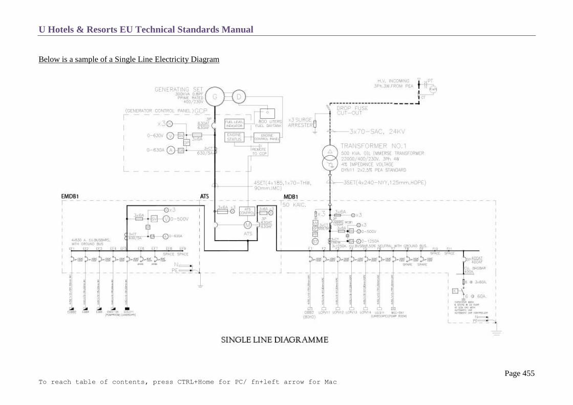
U Hotels & Resorts EU Technical Standards Manual
Page 455 To reach table of contents, press CTRL+Home for PC/ fn+left arrow for Mac
Below is a sample of a Single Line Electricity Diagram

U Hotels & Resorts EU Technical Standards Manual
Page 456 To reach table of contents, press CTRL+Home for PC/ fn+left arrow for Mac
Electricity System Diagram

U Hotels & Resorts EU Technical Standards Manual
Page 457 To reach table of contents, press CTRL+Home for PC/ fn+left arrow for Mac
Electricity System Diagram

U Hotels & Resorts EU Technical Standards Manual
Page 458 To reach table of contents, press CTRL+Home for PC/ fn+left arrow for Mac
Electricity System Diagram

U Hotels & Resorts EU Technical Standards Manual
Page 459 To reach table of contents, press CTRL+Home for PC/ fn+left arrow for Mac
Electricity System Diagram

U Hotels & Resorts EU Technical Standards Manual
Page 460 To reach table of contents, press CTRL+Home for PC/ fn+left arrow for Mac
Electricity System: MDB and Generator Room

U Hotels & Resorts EU Technical Standards Manual
Page 461 To reach table of contents, press CTRL+Home for PC/ fn+left arrow for Mac
TRANSFORMATION – HIGH VOLTAGE EQUIPMENT
General Provisions
The supply and transformer stations will contain, unless indicated otherwise by the distributors:
switched input cells according to type of distribution
1 metering device and general high voltage circuit breaker
transformer protection cells
transformers
The supply station and transformer station will preferably be located in the same room, or in two adjacent rooms.
Failing this, the transformer station will be supplied via 2 looped medium voltage cables.
Constitution and Equipment
The installed transformer capacity will be as calculated from basic capacities, using packing factors and multiplied by 0.8, plus 50% increase.
If there is no recommended requirement, the transformer station will be composed of pre-fabricated cells.
The insulating voltage and the breaking power will be matched to the distributor’s network.
The cells will be equipped with regulation mechanical locking systems and protection screens, as specified by the distributor.
The front panel of the cells will contain the synoptic diagram of the installation created in aluminium strips, with invisible fixing and engraved
inscriptions clearly indicating the nature of the cell and function of the control equipment.
The unifiliar diagram of the station will be placed in a frame underneath transparent plastic film.

U Hotels & Resorts EU Technical Standards Manual
Page 462 To reach table of contents, press CTRL+Home for PC/ fn+left arrow for Mac
Transformer Room
U Hotels & Resorts EU Technical Standards Manual
Page 463 To reach table of contents, press CTRL+Home for PC/ fn+left arrow for Mac
GENERAL LOW VOLTAGE PANEL
Shell
The entire low voltage panel will take the form of pre-fabricated cells
The units will be of steel protected against corrosion and coated with two layers of glycerophtalic paint.
Separate metering systems will be provided for:
o laundry
o chilled-water/cold production and air-handling units
o kitchen (if using electricity)
o extractors
Electrical Equipment
General circuits leaving the low voltage panel will be separated:
o on the one hand into power circuits (1 circuit per installation the capacity of which is≥ 30 kVA)
o on the other hand, socket and lighting circuits.
The minimum insulation voltage will be at least 500 V.
Circuit protection equipment will consist solely of circuit breakers. All circuits are individually protected and switched.
All equipment must carry short circuit currents during the time needed for operation of protection.
In particular, where protection is provided via a fuse with associated circuit breaker with high breading power, fuses must be calibrated to act
before the short circuit intensity has reached a figure that will be dangerous for the circuit breaker.
Total selectivity must be guaranteed between protection of supply and protection of outlets.
Distribution will be made in such a manner as to identify inputs and outputs.
U Hotels & Resorts EU Technical Standards Manual
Page 464 To reach table of contents, press CTRL+Home for PC/ fn+left arrow for Mac
Measuring Apparatus
Measuring units will be recessed into the front panel of the cells.
The following equipment will be provided:
o 1 indicator voltmeter per set of bars with commutator including an “off” position
o 1 indicator ampere meter per phase
o 1 3-phase power factor indicator.
Installation Balancing
The power factor of the installation will be automatically raised to the figure required by the local distributor.
This installation will comprise a battery of protected condensers, with non-flammable dielectric insulator placed in a low voltage panel cell and
provided for each power transformer.
The batteries must be capable of carrying voltage exceeding their nominal voltage by at least 10% without damage.
The insulation level will be 3 kV.
Each battery will be equipped with an integral discharge device.
Power Allocation
Outlets from the sets of bars will be distributed so as to balance the load on transformers. A mechanical locking system will prevent
transformers from being placed in parallel.

U Hotels & Resorts EU Technical Standards Manual
Page 465 To reach table of contents, press CTRL+Home for PC/ fn+left arrow for Mac
CABINETS
General Remarks
Secondary panels established for each zone will have general protection for lighting.
All circuits will be linked to ground without exception. At all points the ground resistance will be below 100 Ohms
In general, secondary circuits will be sub-divided in such a way that each monophase circuit supplies no more than 8 light points or 8 10/16 A
sockets.
Circuits will be loaded to maximum of 70% of their capacity.
Circuit breakers will be preferred to fuses.
All socket circuits and bathroom circuits will further be protected by 30 mA differential circuit breakers.
All other circuits will further be protected by differential circuit breakers, rated as adapted to the installations, individually or by group of the
same nature.
All panels will be designed to have 30% spare outlets.
The unifiliar diagram for the panel will be placed under plastic in the cabinet.
The hotel building itself (rooms) will be supplied by one or more floor panels set up in wall-mounted cases with distribution by conduit to the
bedroom protection panels located in cases placed between 2 bedrooms.
Metering = see section 3 above.
Floor Panels
Floor panels will be constructed with a frame, painted with one layer of anti – rust paint and 2 coats of glycerophtalic paint, carrying all the
equipment.
This frame will be mounted either in a polyethylene case forming a cabinet with a door, which is lockable, where the panel is of the visible type
(in particular in technical rooms and general services), or directly within a masonry shaft, with lockable door for other building distribution
panels. Accessibility of equipment in the shafts must be ensured.
The frame should be equipped with horizontal rails that can be adjusted for height and depth. The rails will carry all the equipment.
Inputs and outputs will be done through clamped terminal strips.
Metal labels fixed to the front, below each control or protection unit will identify all circuits.
Cabling will run through a plastic trough placed in the same plane as the equipment, so as to be easily accessible.
One output per bedroom is necessary.
General services for each floor will be supplied from the floor panels.

U Hotels & Resorts EU Technical Standards Manual
Page 466 To reach table of contents, press CTRL+Home for PC/ fn+left arrow for Mac
Bedroom Panels
Function:
Each panel will have at the in lead and for each room a general switch, a thermal circuit breaker, and a 30 m amp differential type modular
circuits’ breaker. There will then be 5 outputs per room:
o 1 lighting output
o 1 output for fan-coil and refrigerator, TV and desk in the suites
o sockets, independent of the general switch
o 1 output for sockets
o 1 output for the bathroom
o 1 output for bathroom emergency light point
For each room, at least these 5 circuits are to be provided. They are protected individually by micro circuit breakers.
(Also refer to Chapter C2)
Constitution
They are located in a position not normally accessible to guests.
They will take the form of a PVC box that will be impermeable to jets of water and will be connected through the bottom.
The internal frame will be equipped with rails carrying the equipment.
Below a sample diagram of an in room RCU (Room Control Unit)
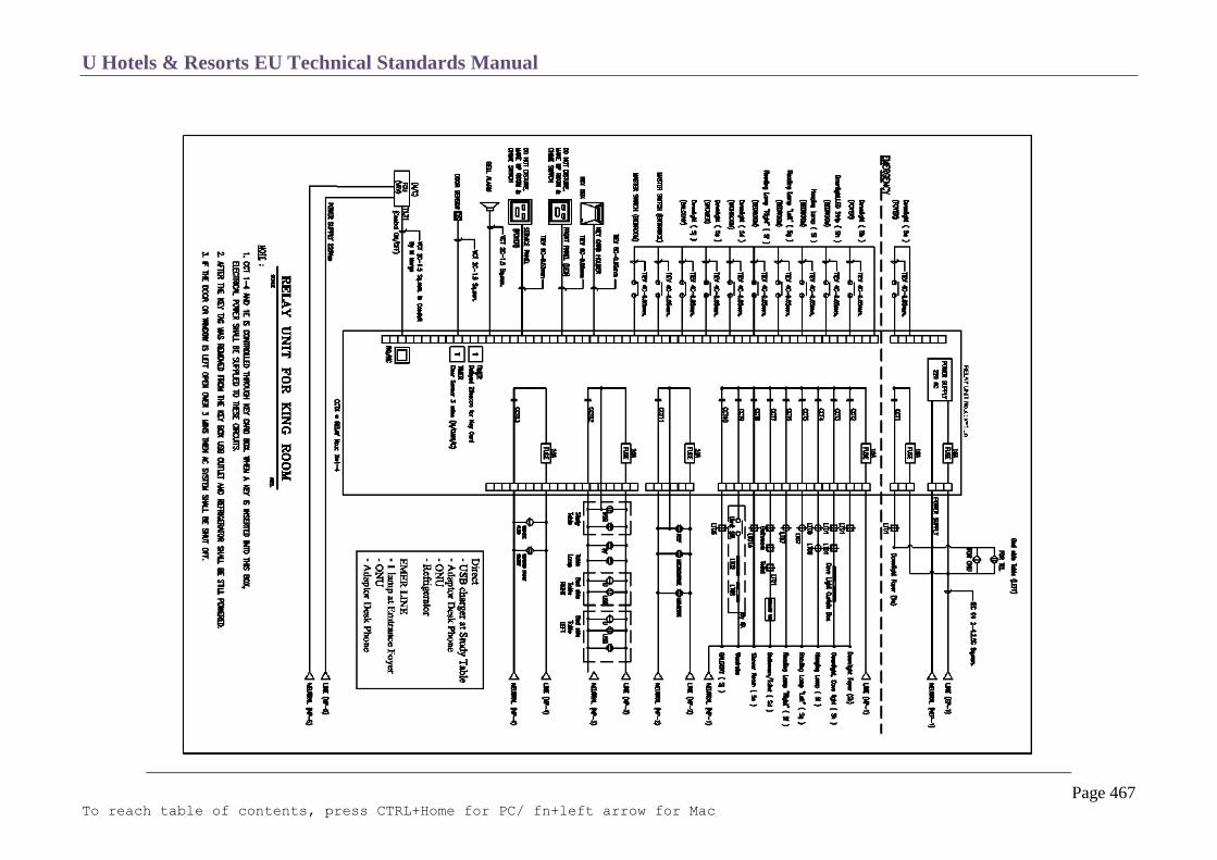
U Hotels & Resorts EU Technical Standards Manual
Page 467 To reach table of contents, press CTRL+Home for PC/ fn+left arrow for Mac

U Hotels & Resorts EU Technical Standards Manual
Page 468 To reach table of contents, press CTRL+Home for PC/ fn+left arrow for Mac
Technical Rooms’ Panels
Technical room panels will have on the front all the warning lighting and the control switches and push buttons.
Safety Panels
Safety equipment will be supplied via special panels, which are fire resistant and which comply with the relevant fire standards.

U Hotels & Resorts EU Technical Standards Manual
Page 469 To reach table of contents, press CTRL+Home for PC/ fn+left arrow for Mac
DISTRIBUTION
Lighting Levels
The lighting levels to be observed in the various rooms are defined below:
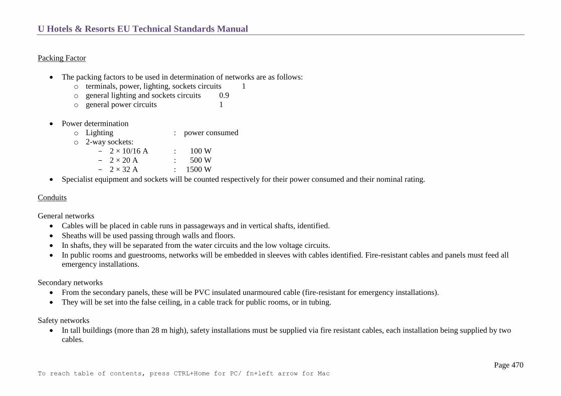
U Hotels & Resorts EU Technical Standards Manual
Page 470 To reach table of contents, press CTRL+Home for PC/ fn+left arrow for Mac
Packing Factor
The packing factors to be used in determination of networks are as follows:
o terminals, power, lighting, sockets circuits 1
o general lighting and sockets circuits 0.9
o general power circuits 1
Power determination
o Lighting : power consumed
o 2-way sockets:
2 × 10/16 A : 100 W
2 × 20 A : 500 W
2 × 32 A : 1500 W
Specialist equipment and sockets will be counted respectively for their power consumed and their nominal rating.
Conduits
General networks
Cables will be placed in cable runs in passageways and in vertical shafts, identified.
Sheaths will be used passing through walls and floors.
In shafts, they will be separated from the water circuits and the low voltage circuits.
In public rooms and guestrooms, networks will be embedded in sleeves with cables identified. Fire-resistant cables and panels must feed all
emergency installations.
Secondary networks
From the secondary panels, these will be PVC insulated unarmoured cable (fire-resistant for emergency installations).
They will be set into the false ceiling, in a cable track for public rooms, or in tubing.
Safety networks
In tall buildings (more than 28 m high), safety installations must be supplied via fire resistant cables, each installation being supplied by two
cables.

U Hotels & Resorts EU Technical Standards Manual
Page 471 To reach table of contents, press CTRL+Home for PC/ fn+left arrow for Mac
Sockets
Surface-mounted:
These will be of two types:
o in wet service rooms: PVC waterproof units, fed via visible conduit and supplied with the corresponding plugs.
o in technical rooms: metal industrial type sockets, supplied with the corresponding plugs.
Recessed, flush-mounted type (all public rooms and other service rooms):
o Secured by screws.
o The twin sockets will be mounted on a single insulation backing plate.
o Shaver sockets will be of the International, multiple-pin type, with safety transformer (dual voltage).
Switches
The mechanism will be of the silent type.
o Surface mounted:
o Placed in technical rooms and wet service rooms. Waterproof, PVC, fed via surface mounted conduit.
o Flush (all public rooms and other service rooms): Attached by screws.
Light fittings
Light fittings will be selected to:
o guarantee illumination with the best possible yield in the specific conditions of the room and the use to which it is put,
o be sturdy, easy to maintain and of pleasing appearance,
o comply with safety conditions.
For general illumination, the uniformity factor must not be below 0.8.
The position and type of light fittings will be such that there is negligible glare.
All the above data will be valid apart for rooms having accent and decorative lighting. For such rooms, it is essential that a lighting specialist
should be consulted (public rooms and guestrooms).
The colour – rendering index of sources will lie between 70 and 85.
For bathrooms, one may use either incandescent lamps or fluorescent lamps with “luxury” white tubes having a colour rendition index of 95.

U Hotels & Resorts EU Technical Standards Manual
Page 472 To reach table of contents, press CTRL+Home for PC/ fn+left arrow for Mac
Light fittings will selected in relation to the rooms in which they are placed (dust, humidity, impact resistance, electrical safety, double
insulation within 60 cm of showers, category for thermal behaviour) and must not give rise to noise. The number of different fixture types will
be restricted to those most suitable, as standardization must be aimed at.
Access to bulbs and accessories must be easy for exchange and maintenance.
In public areas, light fittings must be of incombustible materials in any tall building (above 28 m), or difficult to ignite in other cases.
Ease of cleaning must be ensured.
Dimmer switches for public rooms:
Dimmer switches installed in emergency circuits will have a device which, if current is interrupted in that circuit, will short circuit the dimmer
switch and the main switch and will give 100 % illumination for the circuit.
Their capacity will be adjusted to the room concerned. Special research must be carried out if involving fluorescent tubes.
Positioning of dimmers will be chosen in a discreet manner.

U Hotels & Resorts EU Technical Standards Manual
Page 473 To reach table of contents, press CTRL+Home for PC/ fn+left arrow for Mac
SAFETY LIGHTING
Location
Passageways, exits and emergency exits will be identified by battery-fed safety lighting fixtures of the 60 lumens type.
The battery-fed safety lighting fixtures will have notices “exit”, “emergency exit”, “→” according to disposition. Apart from the regulation
position, certain fixtures can be placed lower down, in order to facilitate evacuation in the case of explosion or fire.
Nature
In general, safety lighting, unlike emergency lighting (see below) will be of the non-permanent type, except for the ballroom where such
lighting, according to the equipment and classification of the building, must be of the permanent type, with emergency power supply and buffer
batteries.
Start-up in the event of any breakdown in the power mains supply will be undertaken via a remote-control device acting on all the fixtures in
the same installation.

U Hotels & Resorts EU Technical Standards Manual
Page 474 To reach table of contents, press CTRL+Home for PC/ fn+left arrow for Mac
EMERGENCY GENERATING SETS
Installations to be Protected
Installations to be protected by generating sets will be as follows:
o auxiliary units of the generating sets
o lighting in passageways, public rooms and technical rooms (1/3 of each installation including safety lighting fixtures and safety lighting
in general.
o ambient lighting in bathrooms (1 point)
o firemen’s public and service elevators necessary for safety
o a minimum of 1 public + 1 service elevators, with other units being brought down to ground floor level (with time delay starting).
o all extraction fans
o distribution of hot and cold water for domestic use.
o circulation pumps
o booster pumps (and fire boosters)
o mechanical smoke removal devices
o lift pumps
o fire network pumps
o cold rooms and cold stores
o certain kitchen equipment (see section C 14 Kitchens) and 50% of kitchen lighting
o all low voltage installations, including the Fidelio Opera Express connections and all I.T. equipment.
o computerized cash-registers and the electronics management system (P.O.S, P.M.S).
o detection, alarms and monitoring system, control room (B.C.S),
o indication of positions of fire dampers and of elevator fire doors.
o automatic doors
Installations which are not protected will be automatically cut off as soon as there is a power mains breakdown and the generating sets start up.
Fire safety installations will be given priority supply.

U Hotels & Resorts EU Technical Standards Manual
Page 475 To reach table of contents, press CTRL+Home for PC/ fn+left arrow for Mac
Number of Sets
Where a building is less than 28 meters high, for protected installations operations a single set will be provided if the protected P <400 kVA,
and 2 sets if protected P >400 kVA.
If the building is more than 28 meters high, or should it be essential for the electrical power plant to operate continuously (low reliability of
distributors’ supply network) at least 2 generating sets will be provided, each capable of:
the first to provide supply to building safety installations
the second to provide supply to protected building installations.
In that configuration, the protected installations are automatically cut off in the event of breakdown of one of the sets.
Set Specification
Engine:
The diesel engine will be of the low or medium speed type, designed for hard work and using diesel fuel. The average consumption must be
below 170 g/hp/h.
The intake system will be of the supercharged type, with maximum 60% supercharging rate.
The engine will be designed for easy access and will have at least individual cylinder heads and lateral doors that allow piston rods and pistons
to be assembled without doing more than removing these doors.
Engine pre-heating will be carried out by electrical resistances which are immersed in the cooling water circuit on the one hand and by a
water/oil exchanger for the lubrication circuit on the other hand.
The engine will have a cartridge air filter which must keep back 85% of particles with a diameter of more than 5 microns.
Each engine will be equipped with an electronic speed regulator.
The instantaneous variation in speed after a sudden variation from full load to zero, or conversely, must not exceed 10% of the nominal value
and the speed must be brought down within steady state speed limit ( + 2%) in less than 3 seconds.
The variation in speed figure will be between + 2% as between no load running and full load running.
In all cases, the speed will be stabilized without pumping after 5 seconds.
Hoods will protect the flywheel, as well as all moving parts.

U Hotels & Resorts EU Technical Standards Manual
Page 476 To reach table of contents, press CTRL+Home for PC/ fn+left arrow for Mac
Cooling:
An air-cooling tower for each set will be located outside and will be designed for permanent operation compatible with the temperatures at the
site.
It will be made of non-corroding material or protected by metal treatment against corrosion.
Start-up of the cooling tower fan will be linked with operation of the set. The cooling tower will be stopped during start-up of the engine until it
reaches operating temperature.
An expansion tank will ensure that the cooling circuits are constantly filled.
All piping between the thermal engine and the cooling tower will be made of seamless steel tubing.
Minimum hourly surcharge of 10%, every 12 hours in the climatic conditions of the site.
Alternator:
The alternator will have the following characteristics:
continuous operation
vacuum impregnation
screen protected rainproof protection
heating up below 100˚C
accuracy of no-load or on-load regulation for nominal power factor of 0.8 f or sudden variation in normal loading, current will be re-established
in less than 0.6 seconds
surcharge: 10% for 1 hour every 12 hours without permanent heating
harmonic distortion between phase and neutral <1%
total harmonic distortion, including harmonic 3 <3%
Load ballast:
In order to carry out operational tests of the set at 40% minimum load, load ballasts (power = 40% minimum of set power) made up of stainless
steel resistances (18/8) are provided to operated cooled by forced ventilation.
Maximum heating up will be 250˚C and the fusion point will be above 1,300˚C.

U Hotels & Resorts EU Technical Standards Manual
Page 477 To reach table of contents, press CTRL+Home for PC/ fn+left arrow for Mac
Start-up:
The generating set will have automatic starting, in the event of power mains breakdown. Power flow will be established in less than 10 seconds.
Stoppage when the power main is recovered will be carried out with time delay of:
o minutes at normal speed
o minutes at decreasing speed
Compressed air system:
This system will be used for engines having power above 500 hp.
Capacities of air bottles will be sufficient to give six start-up tests without refilling.
The air will be supplied via an automatic starting electric compressor, which will allow the reserve to be filled in a maximum of one hour and in
an emergency by a compressor driven by a diesel engine.
The air bottles will be equipped with valves, safety valves, and manometers, with isolation cock.
The inside of the bottles will be treated so as to prevent any oxidation.
Electrical system:
The system is used for engines with power of under 500 hp.
The electric starter will be supplied from a lead battery. Capacity will be sufficient to give six start-up tests without recharging.
The charger will operate automatically and will have 2 conditions: charging and maintenance.
It will be designed to carry without deterioration:
o the output obtained with low battery
o a clear short circuit at the use terminals.

U Hotels & Resorts EU Technical Standards Manual
Page 478 To reach table of contents, press CTRL+Home for PC/ fn+left arrow for Mac
Emergency system:
Whatever the starting system, an emergency starting system must be provided.
Cut-off:
If there is a breakdown in power supplied by the distributor and the generating set starts up, unprotected general electrical panel outputs are
automatically cut off by the contact opening.
If the power mains supply is restored, these outputs will be automatically cut in by closure of the contactor.
Exhaust:
The exhaust system will comprise of:
o one silencer per set, providing attenuation compatible with the two noise levels
o permissible in the different premises of the hotel or in the neighbourhood according to the “acoustic” requirements (see Chapter C20),
o steel horizontal pipe, with sealed expansion collar,
o vertical pipe taken through bronze rollers and expansion device placed in masonry shaft.
The entire exhaust system will be sealed for waterproofing and must not transmit vibrations to neighbouring portions.
It will be insulated so as to restrict the external temperature of the pipes to 80˚C.
The overall pressure drop from the exhaust piping (including the silencer) must not exceed 250 mm water height.
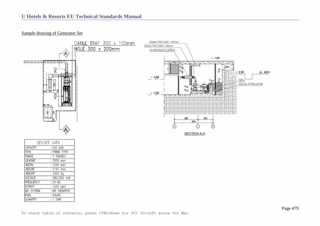
U Hotels & Resorts EU Technical Standards Manual
Page 479 To reach table of contents, press CTRL+Home for PC/ fn+left arrow for Mac
Sample drawing of Generator Set
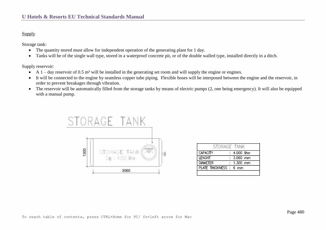
U Hotels & Resorts EU Technical Standards Manual
Page 480 To reach table of contents, press CTRL+Home for PC/ fn+left arrow for Mac
Supply
Storage tank:
The quantity stored must allow for independent operation of the generating plant for 1 day.
Tanks will be of the single wall type, stored in a waterproof concrete pit, or of the double walled type, installed directly in a ditch.
Supply reservoir:
A 1 – day reservoir of 0.5 m³ will be installed in the generating set room and will supply the engine or engines.
It will be connected to the engine by seamless copper tube piping. Flexible hoses will be interposed between the engine and the reservoir, in
order to prevent breakages through vibration.
The reservoir will be automatically filled from the storage tanks by means of electric pumps (2, one being emergency). It will also be equipped
with a manual pump.
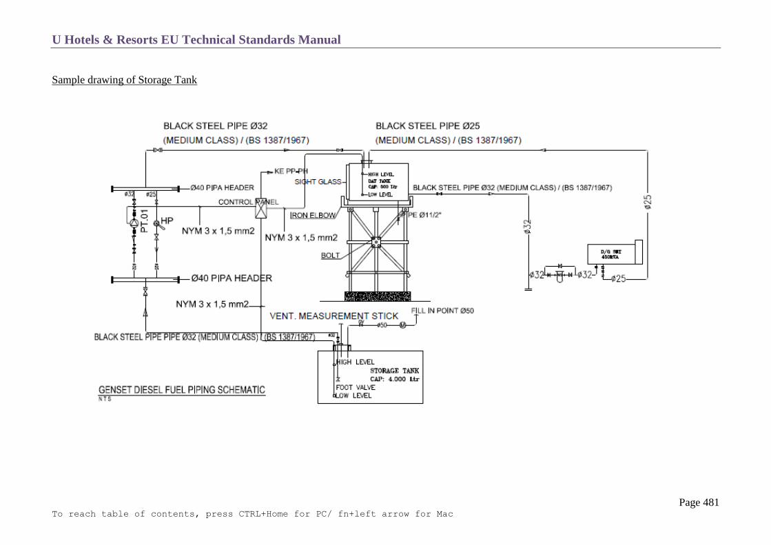
U Hotels & Resorts EU Technical Standards Manual
Page 481 To reach table of contents, press CTRL+Home for PC/ fn+left arrow for Mac
Sample drawing of Storage Tank
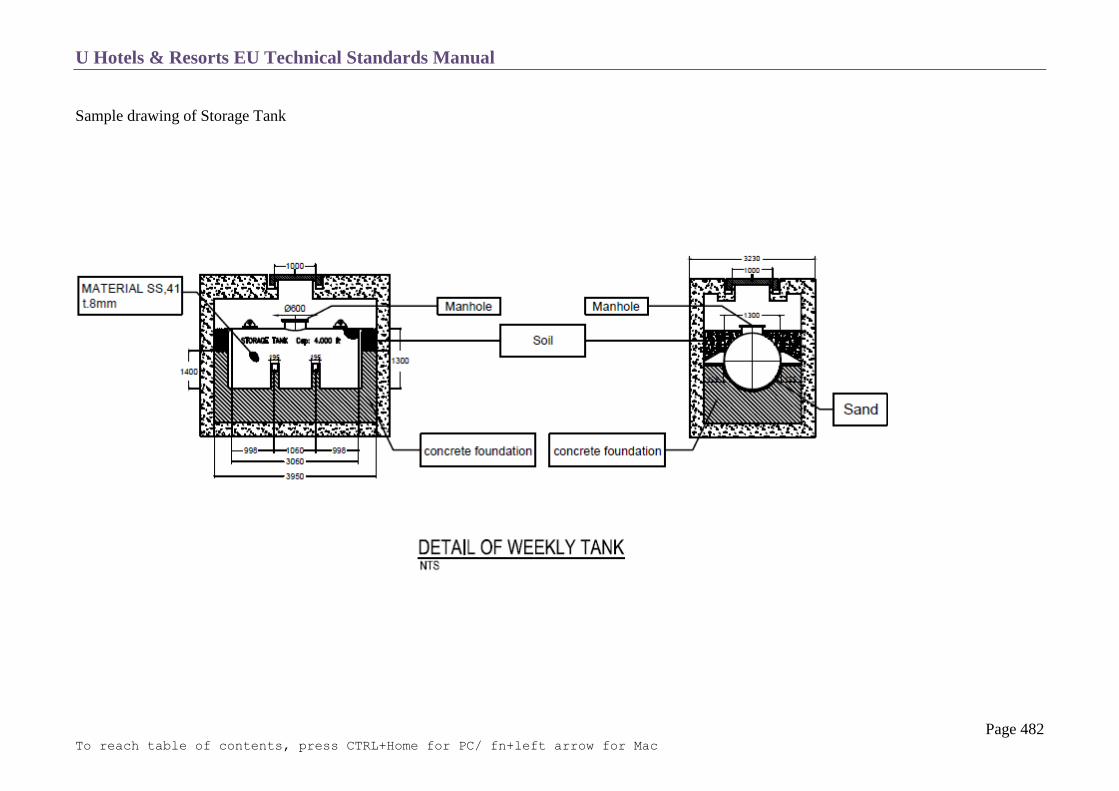
U Hotels & Resorts EU Technical Standards Manual
Page 482 To reach table of contents, press CTRL+Home for PC/ fn+left arrow for Mac
Sample drawing of Storage Tank
U Hotels & Resorts EU Technical Standards Manual
Page 483 To reach table of contents, press CTRL+Home for PC/ fn+left arrow for Mac
LIGHTNING PROTECTION
A lightning conductor system will be designed case by case, in particular for tall, or isolated structures, and in zones where the keraunic level is
over 25 (or NG max = 2 NG = 2,25 impacts/year/km²) and installed in such a way as to cover all buildings constructed.
As the case may be, and taking into account aesthetic problems, preference will be given to systems in a Faraday cage, or possibly lightning
conductor with arcing device.
It will comprise of:
Copper or stainless steel capturing points, with diameter of more than 18 mm located at the top, on the periphery and on all projecting portions
of roofs. These points will have a maximum spacing of 10 meters (or 15 m) for a height of 30 cm (or 50 cm).
Flat roof conductors (30 × 2 mm), forming a mesh of 15 m maximum and joining the points together (Faraday cage).
Identical vertical conductors, placed at the angles and projecting portions of the building constituting a mesh cage and taking the shortest route
to ground. (Buildings using an exposed and continuous metal framework can use this in lieu of the conductors linking between the points and
the ground).
The conductors will be protected against impact, particularly up to minimum height of 2 m from the ground. Each vertical conductor will be equipped
with a ground measurement bar.
A specific ground connection, with resistance below 10 Ohms, linked to the ground of the electrical installations of the building. This will be
comprised of conductors which are identical to the vertical conductors, arranged in goose foot pattern at a depth of more than 60 cm and having
a length of 2 to 3 m for each vertical conductor, with a linking belt of the same nature (the grounding system for electrical installations,
comprising a loop at the base of a trench, can form this link).
On the other hand, the electrical installation will be protected by an anti- lightning system installed immediately after the main connection
circuit breaker if it is differential.

U Hotels & Resorts EU Technical Standards Manual
Page 484 To reach table of contents, press CTRL+Home for PC/ fn+left arrow for Mac
IT & LOW VOLTAGE
Computer Room
Structured Cabling
Unstructured Cabling
Background Music System
Audio Visual Equipment For Conference Facility
Access Control System
Electronic Clocking-on System
Hospitality Information Technology Systems
IPTV System
Automatic Wake-up Call Function

U Hotels & Resorts EU Technical Standards Manual
Page 485 To reach table of contents, press CTRL+Home for PC/ fn+left arrow for Mac
COMPUTER ROOM
This room is required to be secured from unauthorized access, under lock & key and has special needs; power supply comes from the emergency generator
grid with independent air condition units in addition or in lieu of the normal AC. The location of the server room can be anywhere as long as the following
considerations are adhered to:
Not below any pipes carrying liquids or which are required to have periodic maintenance
Air ducts serving other areas must not pass through the Server Room
Not adjacent to engineering facilities such as generator rooms, electrical switch gear rooms, air-condition units, any kind of compressors and
electric motor facilities
A location without the risk of damage or exposure to fire, water, heat, dust, corrosive fumes, heat and smoke
Not adjacent to a ‘busy corridor’ area and certainly not in any areas from which the general public may have access to.
The server room must have a raised floor and wide doors (above standard) to allow for equipment to pass comfortably.
The floor immediately above the Server Room must be watertight and any openings in the Computer Room ceiling, walls or floor must be sealed
to the full thickness of the ceiling, wall, or floor.
Walls, floors, ceilings and doorways should have a one hour minimum fire resistance rating carried to the underside of the construction. All
materials used in the construction of the Computer Room including walls, floors, ceilings, raised floors, partitions etc. should have flame spread
ratio of 25 or less. Doors should have a minimum 60 minute fire proof rating.
No signs, directions, or public-facing windows indicating or revealing the presence of the IT&T facility.
Besides industry sized computer racks, steel or metal shelves and metal furniture are recommended (wood and plywood are not suitable)
Room Size
Server rooms for smaller hotels should be between 8-10m² to accommodate all computer servers housed in 42U sized racks (2-3) with following
equipment’s;
o Uninterruptible power supply (UPS)
o Telephone systems (PBX)
o Fire suppression system FM200 or Novem1230
o Air condition, two units to have guaranteed 24hour coverage
o Main distribution frames for data and power (MDFs)
o Working desk with chair and all manuals

U Hotels & Resorts EU Technical Standards Manual
Page 486 To reach table of contents, press CTRL+Home for PC/ fn+left arrow for Mac
Fire Protection
A special and separate fire protection for the equipment inside the computer room is necessary to protect the systems from fire and water damage caused
by the normal water based sprinkler systems. The gas from this system is non- toxic and not harmful to people. The installation of this system needs to
be performed by a company which specialized in firefighting equipment installation and is recognized by local building and safety authorities. The image
below illustrates the system but may differ from your environment.
It is recommended to use FM200 or Novem1230 clean agent type of system.

U Hotels & Resorts EU Technical Standards Manual
Page 487 To reach table of contents, press CTRL+Home for PC/ fn+left arrow for Mac
Lighting
Computer room requires 350 Lux
All lights within the room need to be connected to the UPS grid
LED or fluorescent lights in sufficient quantity should be used

U Hotels & Resorts EU Technical Standards Manual
Page 488 To reach table of contents, press CTRL+Home for PC/ fn+left arrow for Mac
Power Supply
Clean and sufficient electrical power at all times is an absolute requirement. Power is supplied from the common grid, the emergency generator grid and
the UPS (uninterruptable power supply) with battery back-up. A single Phase 3 to 5kVA UPS with battery back-up is required and built into each
computer rack.
The UPS MCB board distributes power to:
o each of the computer racks
o wall socket outlets opposite the computer racks at 1000mm height from the floor which serves for occasional maintenance equipment to
be connected
o all fluorescent lights in the server room
o the fire suppression system
Electrical Ground or Earth Wire:
o It is most important that ALL EQUIPMENT (UPS, PABX, computer racks etc.) are connected to a very good ground connection.
Part of the commissioning of any parts of the IT&T installation is scientific proof of acceptable ground connection.

U Hotels & Resorts EU Technical Standards Manual
Page 489 To reach table of contents, press CTRL+Home for PC/ fn+left arrow for Mac
Air Conditioning
Systems function best in a cool, dry and well ventilated environment. To assure a stable environment, air conditioning units need to be installed and
function continuously:
The Server Room will have a primary air-conditioning system, usually a ceiling mounted fan coil, supplied from the building central system,
capable of providing a room temperature of 18°C to 20°C (max 23°C).
In some regions the requirement for dehumidification must also be examined to maintain a 40% - 50% relative humidity in the room.
Air ducts serving other areas must not pass through the Computer Room
An independent, back-up air-conditioning unit, usually a split DX system, must be installed and connected to the emergency power grid so that in
case of mains power failure, cooling will continue to be available. A malfunction alarm for the air conditioning unit or a high temperature alarm
for the Server Room must be located where the resort’s fire alarm panel is located to assure this is monitored continuously
Special care must be taken when condensation water returns are installed to avoid these running close to any IT&T equipment
Cable Routing in the Computer Room
The cable routing for both, power and data is from ceiling trays dropped into the racks.
Important: data cables (fibre-optic and copper) require smooth bending radius and appropriate cable trays designed for IT must be used.
Cable damage is the most common and a costly expense in IT budgets.

U Hotels & Resorts EU Technical Standards Manual
Page 490 To reach table of contents, press CTRL+Home for PC/ fn+left arrow for Mac
STRUCTURED CABLING
The objective of a structured cabling system is to unify over a single cable infrastructure the transmission of data, voice and video. This cabling system
used the Internet Protocol (IP) signal to transmit the information. The network bandwidth has to be 1 Gigabyte Ethernet and is required to accommodate
future growth and applications such as TV and Video signal which demand high bandwidth. CAT6, CAT6e and CAT7 1000BASE-TX and Single Mode
Fibre Optical cable 1000BASE-LX should only be used.
Systems such as fire detection are considered as independent for technical reasons at this time, and must be covered separately.
CAT 6 and 6e copper cabling (IP)
This cable consists of eight cores copper cable which are twisted around the middle to guarantee data quality. It is also referred to “UTP cable”
or “unshielded twisted pair”.
Each cable can only be run for a total length of 90 meters.
Patch cords or cable between wall outlets and using device should not be longer than 2 meters.
The same applies to patch cords connecting servers to routers and switches.
Special care must be taken when laying the cables in conduits and on cable trays. Conduits and cable trays need to be at least 50 cm away from
electrical power lines and fluorescent lights to avoid electromagnetic induction.
CAT6, CAT6e and CAT7 (1000BASE-TX) cable will comply with standard installation practices regarding bend radius for copper cables. We
recommend you follow these practices closely for all installations, i.e. 4 times the diameter of the cable. The diameter of a plenum UTP cable is
approximately 0.6 cm.
All cables jackets must be Low Smoke Zero Halogen or Low Smoke Free of Halogen (LSZH or LSOH).
Fibre optical cabling (IP)
Single mode fibre optical cable (SMF) 1000BASE-LX must be used when distances above 90 meters are to be covered.
Depending on the cable run location, either an in-door variety or a shielded out-door type needs to be used.
This type of cable usually covers 5 km of distance. It is important to follow the cable manufacture’s cabling and bend radius instructions. If no
minimum bend radius is specified, one is usually safe in assuming a minimum long-term low-stress radius not less than 15 times the cable
diameter.

U Hotels & Resorts EU Technical Standards Manual
Page 491 To reach table of contents, press CTRL+Home for PC/ fn+left arrow for Mac
Wireless Access Points (Wi-Fi signal distribution)
Ruckus, Zebra, Cisco or Meraki by Cisco branded products should be used to ensure a self-healing and stable Wi-Fi environment.
These products are designed for a large number of concurrent users and seamless mobility within the network.
The set-up consists of a number wireless access points and a single controller.
The selection of the number and models of wireless access points is dependent on each local environment and needs to be determined accordingly
by an authorized dealer.
Wireless Connection Quality Standard
To ensure the wireless connections have excellent quality, the signal strength measured in dBm must be -65 dBm or better in the following
areas
o Guest room: bed, desk, and balcony
o Public areas: lobby area, business centre, restaurant, meeting room, and poolside daybed
Wireless Installation Approach
For typical rooms it is strongly recommended each has a Wi-Fi access point installed.
1 AP (access point) for 2 rooms may be applicable if signal quality meets brand standard.
For lobby, restaurants and meeting rooms or any other high density guest area, high capacity models are recommended.

U Hotels & Resorts EU Technical Standards Manual
Page 492 To reach table of contents, press CTRL+Home for PC/ fn+left arrow for Mac
SYSTEM DIAGRAMME SAMPLE

U Hotels & Resorts EU Technical Standards Manual
Page 493 To reach table of contents, press CTRL+Home for PC/ fn+left arrow for Mac

U Hotels & Resorts EU Technical Standards Manual
Page 494 To reach table of contents, press CTRL+Home for PC/ fn+left arrow for Mac

U Hotels & Resorts EU Technical Standards Manual
Page 495 To reach table of contents, press CTRL+Home for PC/ fn+left arrow for Mac
UNSTRUCTURED CABLING
Coaxial Cable for TVs (only if IPTV is not available)
Cable
Drop cable shall be quad-shielded RG6 that meets all fire codes including plenum space, and is equal to or exceeds Belden 1189A specifications.
Drop lengths shall not exceed 250 feet over RG6. If the drop exceeds 250 feet but is under 500 feet RG11 must be used
All distribution exceeding 250 feet, but under 500 feet shall be quad shielded RG11 that meets all fire codes including plenum space, and is equal
to or exceeds Belden 1617A specifications.
If the distribution exceeds 500 feet Times Microwave hard line or an equivalent must be used
Connectors
Connectors shall be LRC snap-n-seal for all coaxial cable. Connectors for hard line shall meet or exceed Gilbert brand.
Splitters
All splitters and directional couplers shall be 1 GHz band pass, rf shielded, externally grounded, low insertion, return, and tap loss.
They shall also be highly isolated.
Public Address System Cabling
Public Address System cabling is determined by the brand and specifications of the system and contractor chosen which forms part of the Fire
Prevention System installation.

U Hotels & Resorts EU Technical Standards Manual
Page 496 To reach table of contents, press CTRL+Home for PC/ fn+left arrow for Mac
Sample Diagramme of IP Distribution

U Hotels & Resorts EU Technical Standards Manual
Page 497 To reach table of contents, press CTRL+Home for PC/ fn+left arrow for Mac

U Hotels & Resorts EU Technical Standards Manual
Page 498 To reach table of contents, press CTRL+Home for PC/ fn+left arrow for Mac
Audio Visual Cabling in Rooms
To minimize cabling, its costs and constraints as well to guarantee a flawless guest experience, a HD (high definition) media hub should be used
to allow guests to connect PC, camera and iXxx to the TV.
These are available from companies such as TeleAdapt and GuestLink.
The units are available in various configurations and can be placed at the desk, the television set and/or the bed side.
Depending on the HD Media Hub configuration the following cabling is required to the HD Media Hub:
o Power (follow power rating from the vendor)
o Internet CAT6
o HDMI cable to the compatible television set
Background Music Cabling and Public Address System (PA system)
The cabling specifications are supplied by the vendors and may vary depending on the distance to be covered.
A public address system centres around an amplifier and from there to speakers.
Connected to the amplifier are microphones and audio players such as CD/DVD player, USB players and background music systems.
Background music systems are personal computer based and receive the music updates over the Internet and are subscription-based. Speaker
zones are defined and playlists are composed to achieve the desired mood music in each area covered.
NOTE; Public address system speaker cannot be used as music speakers. If background music will be plaid through the same system, it requires
to have music speakers.
Public Address System
The public address system is part of the fire, life and safety devices provided by the same company which installs the fire, life and safety
equipment.
The public address system alerts occupants of an impending emergency, sounding an alarm and announcing safety information.
The system must comply with all local codes required for the official operating licenses.
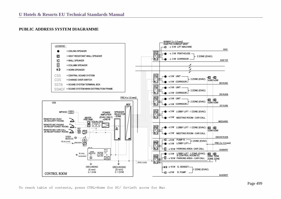
U Hotels & Resorts EU Technical Standards Manual
Page 499 To reach table of contents, press CTRL+Home for PC/ fn+left arrow for Mac
PUBLIC ADDRESS SYSTEM DIAGRAMME

U Hotels & Resorts EU Technical Standards Manual
Page 500 To reach table of contents, press CTRL+Home for PC/ fn+left arrow for Mac
BACKGROUND MUSIC SYSTEM
The background music systems are used to play appropriate mood music in chosen areas of the operation such as outlets, public areas, gym and guest
rooms. The system must comply with national and international public copyright laws in regards to the public performance acts. The systems must be
configurable to play composed lists of music at certain times of the day and different lists in different locations to create different moods at different
times.
Central System
These systems can be installed and maintained centrally on a PC installed with a soundcard in the same location as the public address system.
The music can be played over the central PA system, however if this is the case the speakers will need to follow music specifications.
All public areas like Lobby, Restaurants, Gym etc., should have their own dedicated music designed for their hours of operation, which is piped
to each PA system in the respective location.
Location Specific System
Some systems are deployed near to the locations where the music is to be played and the background music system is connected to local amplifiers
which connect a local set of speakers, independent of the public address system.
In-Room Music
Basic Set Up
Music Styling Company will provide 5 to 6 genres of licensed music located on a computer in the computer room, close to the MATV
system. This will be fed through the MATV system as individual channels to the IPTV
Advanced Set Up
IPTV will have several in-room entertainment programs included Gaming, TV, Music, Local Info, Newspapers etc. This system would
be interfaced with the PMS system, which could do also handle room service orders etc.

U Hotels & Resorts EU Technical Standards Manual
Page 501 To reach table of contents, press CTRL+Home for PC/ fn+left arrow for Mac
AUDIO VISUAL EQUIPMENT FOR CONFERENCE FACILITY
Operating Principles
The ballroom should be divided into 2 or 3 zones, each with its own equipment.
It must be possible to combine all this equipment when the whole room is used.
o The ballroom should be equipped with the following:
o Acoustic equipment for sound broadcasting, divided into several zones
o LCD projectors
o Retractable matt-white screens
The meeting rooms should be equipped with the following:
o Acoustic equipment for sound broadcasting
o LCD projectors
o Retractable mat-white screens
The central audio-video unit located in the sound or technical control room includes:
o Electrical acoustic equipment for recording and broadcasting sound
o An audio/video monitoring system
o An audio dispatcher
o A video dispatcher
Central Audio – Video Unit
The central audio-video unit should comprise of the following:
A mixing console integrated into a worktop.
An audio rack with:
o A branching table bringing together all the returning cables from the different rooms
o Amplifier frames corresponding to the zones of the ballroom or the various meeting rooms
o A graphic equalizer system for the different areas
o Audio monitoring equipment including an amplifier and monitor speakers
o Recording and broadcasting equipment (DVD players)

U Hotels & Resorts EU Technical Standards Manual
Page 502 To reach table of contents, press CTRL+Home for PC/ fn+left arrow for Mac
A rack with:
o A branching table bringing together all the returning cables from the different rooms
o A DVD distribution system including high=performance distributors compatible with all the composite signals
o A monitoring system comprising a selector and a monitor
Installation in the Rooms
Lighting control panel (comprising switches, dimmers and pre-programmed controls) located next to the entrance.
Audio visual equipment, installation and training on the operation should be performed by a professional audio visual consultant.
The equipment should be completely independent with a zone-based installation and should comprise the following:
All rooms:
o Speakers flush-mounted into the false ceiling, minimum power of 4 watts, with a rigid metal grille
o Conference cabinets (see chapter C-12, ballroom and meeting rooms). These cabinets, located on all 4 sides of the rooms, provide the
following:
telephone connection points
video connection points
audio and video fold back connection points linked to the control room
electrical points
protected power outlets
microphone connection points
“raise” and “lower” controls for the screen (which is flush-mounted in the false ceiling)
closure control for the blackout curtains
LCD projector control
slide projector control
Ballroom
High performance ceiling mounted projector(s), HDMI connectivity, 3,000-5,000 lumens, up to 300 inches (7.6m) diagonal projection,
native resolution XGA 1024x768 pixels with Wi-Fi connectivity
Suitable sized, retractable projection screen(s)
Fixed and/or portable LED TV sets minimum 55” (1.4)
Microphones (Podium, Table, Floor) wired and wireless (VHF or UHF)

U Hotels & Resorts EU Technical Standards Manual
Page 503 To reach table of contents, press CTRL+Home for PC/ fn+left arrow for Mac
Lapel microphone - wireless (VHF or UHF)
6 channel microphone and line mixer
DVD player and recorder
Independent sound system and speakers
Internet (wired and Wi-Fi), telephone and TV connectivity
electrical connection boxes hidden behind hatches in the false ceiling, above fixed suspension bars or plates with double hooks (for
suspending spotlights or lighting bridges)
electrical rails with low-voltage spots, set into the false ceiling around the edges of the rooms
Function Rooms
High performance ceiling and/or desk projectors, 2,000 lumens, 40-246 inches (1-6m) diagonal projection, native resolution XGA
1024x768 pixels, build in speakers
Suitable sized, retractable projection screen(s)
DVD player
Internet (wired and Wi-Fi), telephone and TV connectivity
White/glass boards build in wall, markers
Portable whiteboards W=69” H=52” Diagonal=77” (W=1.75 H=1.35m Diagonal=1.95m) and Flipcharts, Markers
Electronic Whiteboard, W=69” H=52” Diagonal=77” (W=1.75 H=1.35m Diagonal=1.95m)
Fixed or movable LED TV set up to 55” (1.4m)
Internet (wired and Wi-Fi), telephone and TV connectivity
Signage
Display sets up to 21” (53cm) diagonal dimension in function/ball room area
Web-based management with password access control
Multilingual management interface
Presentation management and scheduling
System event log
Presentation playing log
Presentation play/pause/stop control function

U Hotels & Resorts EU Technical Standards Manual
Page 504 To reach table of contents, press CTRL+Home for PC/ fn+left arrow for Mac
ACCESS CONTROL SYSTEM
As much as possible, key systems should be used to secure administrative and back of house areas, offices, stores etc.
CCTV installation (cameras, recorders, monitors) To save cabling costs and maximize the IP network, it is proposed to use an IP based CCTV system with IP cameras using PoE (power
over Ethernet). At least the following locations need to be covered with surveillance cameras, however it is advisable to contact the
insurance provider to receive further advice:
Front desk
Lobbies and waiting areas
Driveways, access to property
Car park areas
Public area walkways
Pool and recreation areas
Guest room floors
Receiving area
Back of house office area
Back of house corridors and walkways (housekeeping, engineering)
Central Security Surveillance Console
TV screens located in the security room and should comprise the following:
A 50 cm monitor
A multiplexer for 6 cameras with capability for viewing pictures from 4 cameras in separate windows on the monitor or viewing a single
camera in full screen display
A programmable digital recorder
Cameras and Recorders
The cameras installed should be wide – angle video cameras. Cameras in decorated rooms/areas should be integrated with the decor, while
external cameras should be contained in secure, watertight cases.
Cameras should monitor all entrances to the hotel (Employee entrance, car park entrance, and service entrance), emergency stairway exits and
the lobby front desk.

U Hotels & Resorts EU Technical Standards Manual
Page 505 To reach table of contents, press CTRL+Home for PC/ fn+left arrow for Mac
The recorders should be of the digital type.
They shall operate continuously so that at all times a record is kept of the image of all cameras in a sequence of at least 24 hours. They
continuously show the date and time on the recorded picture.
Front Desk Alarm System
The Front Desk and General Cashier should be equipped in all cases with an alarm bell system relayed to the security room.
Television Equipment
The television equipment should comprise the following:
HF modulators:
o The HF modulators should be connected to the audio-video outputs of the DVDs by means of suitable connectors.
o They should transmit the information received to the channels of the collective network.
o They should be of the professional type, with rack-type fixing.
1 dispatch board:
o The dispatch board should be installed, with rack-type fixing, to allow easy access.
o It should have at least 3 audio – video inputs:
one input should be permanently connected by means of a suitable cable to the ballroom (for meetings, conferences etc.)
two standby inputs should be available for external audio-video sources.
Monitors:
A semi-professional – type colour video monitor should be provided downstream of each DVD to allow permanent monitoring of the quality
of the programs transmitted by the audio-video sources.
DVD players : apart from the recording functions they will have the same characteristics and be multi-zoned, for best flexibility of use.

U Hotels & Resorts EU Technical Standards Manual
Page 506 To reach table of contents, press CTRL+Home for PC/ fn+left arrow for Mac
ACCESS CARD SYSTEM SAMPLE
U Hotels & Resorts EU Technical Standards Manual
Page 507 To reach table of contents, press CTRL+Home for PC/ fn+left arrow for Mac
Injecting Programs into the Collective Installation
The following should be provided for the transmission of internal programs (30 simultaneous channels) to the collective installation:
o in the case of a collective installation with selective (single-channel) amplification, 3 single-channel amplifier modules corresponding to
the HP frequency of each modulator .
o in the case of a collective installation with wide-band or wide band by band amplification, a multiplexer with a minimum of 3 channels
and the protective features required to prevent interference between the different channels.
The multiplexer output should be connected by means of a Cat 6 cable for injection into the wide-band or wide band by band amplifier.
Preamplifiers and amplifiers:
The necessary preamplifiers and amplifiers must be provided if reception conditions dictate. One of the three following type of amplifiers may
be used:
o selective (single – channel) amplifier
o wide-band amplifier
o wide band by band amplifier
The use of filters may be necessary to eliminate parasitic frequencies arising from other types of transmissions.
U Hotels & Resorts EU Technical Standards Manual
Page 508 To reach table of contents, press CTRL+Home for PC/ fn+left arrow for Mac
Receivers
Television sets:
39” LCD TVs, with edge back light LED for standard guestrooms
46”LCD TVs, with edge back light LED for suites and bedrooms
Employee cafeteria, recreation room
infra-red remote control
2 HDMI connectors + 2 USB connector
at least 30 pre-selected channels
maximum volume limit in guest rooms
no facility for guests to modify basic settings
The default settings of the television channels should be controlled from the central unit

U Hotels & Resorts EU Technical Standards Manual
Page 509 To reach table of contents, press CTRL+Home for PC/ fn+left arrow for Mac
ELECTRONIC CLOCKING – ON SYSTEM
The electronic clocking-on system is a micro-computer-based attendance management system interfaced with the property management system,
capable of handling fixed, flexi-time and multiple schedules, and 2×8/3×8 shifts.
The system should comprise of:
o A micro-computer
o A communications card
o Software
o A printer
o Two terminals for reading finger prints or eye scanning in the clocking-on area

U Hotels & Resorts EU Technical Standards Manual
Page 510 To reach table of contents, press CTRL+Home for PC/ fn+left arrow for Mac
HOSPITALITY INFORMATION TECHNOLOGY SYSTEMS
Software:
Hotel Guestroom Booking Systems Online hotel reservations are becoming a very popular method for booking hotel rooms. Prior to the internet, travellers wrote, called the
hotel directly or used travel agents to make a reservation which is time consuming and had constant room inventory errors due to the
manual process.
Travellers can book rooms by using several online travel agents to compare prices and facilities at different hotels. Nowadays, online
travel agents (OTA) maintain detailed information about hotels, prices and deals. Many also allow reviews of the traveller to be recorded
with the online travel agent. Online hotel reservations are also helpful for making last minute travel arrangements. Hotels may drop the
price of a room if some rooms are still available, which can be picked up within seconds on the net.
Therefore Absolute Hotel Services has developed with our partners to have the most efficient system to capture more bookings through
the internet, reduce manual work and get fewer errors by atomized bookings.
Due to constant development Absolute Hotel Services put in place a system which is lasting and will be continuously updated by its
partners which does not affect the flow of bookings but actually will enable an increase in booking streams in future as the internet booking
system is constantly evolving.
Partners
Partner / Tool Function
Website by Travelclick Website development, Search Engine Optimization (SEO) and technology support. The website is
managed by the hotel property and supervised by the corporate office.
i-Stay by Travelclick Booking Engine setup and technology support which is interfaced with the (PMS) Property
Management System through the channel manager.
Channel Manager by Siteminder Updates hotel prices and inventories on all Internet platforms like Hotel Website, OTA, GDS and
some online B2B agents etc. at the same time with one entry to be able to adapt immediately to
market changes. Two way interface with the PMS system
Facebook Booking Engine Booking engine through i-Stay on a free basis. If there is a high social activity at site, the engine
could be extended for an additional cost.
Property Management System AHS has partnered with Comanche which provide a complete property management system (PMS)
which does not require interface between front and back of house systems.

U Hotels & Resorts EU Technical Standards Manual
Page 511 To reach table of contents, press CTRL+Home for PC/ fn+left arrow for Mac
U Hotels & Resorts EU Technical Standards Manual
Page 512 To reach table of contents, press CTRL+Home for PC/ fn+left arrow for Mac
Comanche International Property Management Solution (PMS)
This solution includes:
o Front Office / Reservations
o Point of Sales (POS)
o Call Accounting
o Accounts Receivable
o Accounts Payable
o Inventory System
o General Ledger
Anti-Virus Software o Symantec Anti-Virus software. This software has been proven not to interfere with the PMS operation.
o The software is installed in two locations, all notebooks, workstations and servers (client) and a manager module on a dedicated
workstation grade PC in the computer room.
o The manager will update workstations and manage virus outbreaks on the network.
o There are two versions to be chosen from: Microsoft-only networks and Microsoft & Linux networks
High Speed Internet Access Control
Recommended vendors & product:
o Forigate products
o Xpossible Internet Access Management software
Human Resource & Payroll System
Recommended vendors & products:
o Orisoft, Cadena
Alternative systems should be compliant with local regulations & reporting needs:
owners/partners should propose systems for our evaluation
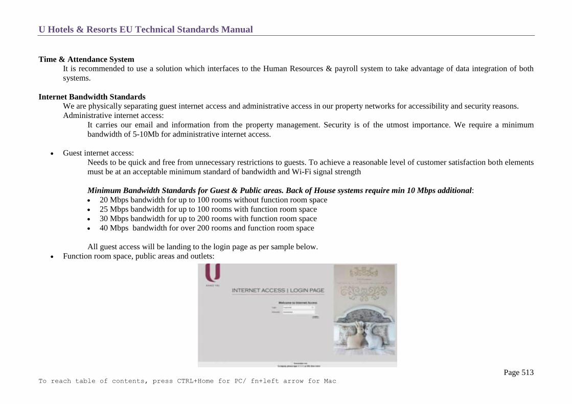
U Hotels & Resorts EU Technical Standards Manual
Page 513 To reach table of contents, press CTRL+Home for PC/ fn+left arrow for Mac
Time & Attendance System It is recommended to use a solution which interfaces to the Human Resources & payroll system to take advantage of data integration of both
systems.
Internet Bandwidth Standards We are physically separating guest internet access and administrative access in our property networks for accessibility and security reasons.
Administrative internet access:
It carries our email and information from the property management. Security is of the utmost importance. We require a minimum
bandwidth of 5-10Mb for administrative internet access.
Guest internet access:
Needs to be quick and free from unnecessary restrictions to guests. To achieve a reasonable level of customer satisfaction both elements
must be at an acceptable minimum standard of bandwidth and Wi-Fi signal strength
Minimum Bandwidth Standards for Guest & Public areas. Back of House systems require min 10 Mbps additional:
20 Mbps bandwidth for up to 100 rooms without function room space
25 Mbps bandwidth for up to 100 rooms with function room space
30 Mbps bandwidth for up to 200 rooms with function room space
40 Mbps bandwidth for over 200 rooms and function room space
All guest access will be landing to the login page as per sample below.
Function room space, public areas and outlets:

U Hotels & Resorts EU Technical Standards Manual
Page 514 To reach table of contents, press CTRL+Home for PC/ fn+left arrow for Mac
These require more Wi-Fi coverage to serve a large number of devices in a relatively small area. There is a need to install more Wi-Fi
access points (antennae) than normally required. The minimum standard for function room space and public areas is one (1) Wi-Fi access
point (all recommended brand high density model) for every twenty-five (50) users.
Bandwidth management (Xpossible v.5 or equivalent):
This solution is required to manage the guest internet, even if it is free to guests. It prevents bandwidth hogging by individual users and
manages downloads by bit torrents etc. This product is recommended and mandatory for Thailand hotels and resorts to comply with the
Thai computer crime act. Details at http://www.xpossible.com/solutions.php.
When total usage reaches 75% of available bandwidth, the following restrictions will automatically be applied:
P2P, bit torrent etc. will be restricted to 10% of total bandwidth
Email and Internet browser will be restricted to 60% of total bandwidth
VoIP will be restricted to 30% of total bandwidth
As soon as total bandwidth consumption falls below 55%, all above restrictions are lifted.
Concurrent access per guest room:
In properties where internet access is free of charge, there is no limit of concurrent users under a single user ID.
Commonly there is one User ID per guest room, however upon request there can be multiple user IDs per guest room thus increasing the
number of concurrent devices.
Login process with Xpossible (or equivalent) for guests free of charge:
We propose to have a 1-screen login process for systems managed with Xpossible version 5 which is composed of the screen including
user ID, password and ICT law agreement statement (Thailand only).
U Hotels & Resorts EU Technical Standards Manual
Page 515 To reach table of contents, press CTRL+Home for PC/ fn+left arrow for Mac
Electronic Mail and Domain Name
Domain Name Registration The AHS marketing department is designated to register the domain name and will set up all necessary pre-opening email accounts and
forward the relevant information to the users.
The TS team will organise Office 365 yearly licenses as official communication platform for the group. After the setting is done the GM
will be responsible for the email accounts. The email administrator login credentials must be sent to AHS Marcom.
Local ISP Electronic Mail Hosting This is not allowed due to safety issues and corporate governance.

U Hotels & Resorts EU Technical Standards Manual
Page 516 To reach table of contents, press CTRL+Home for PC/ fn+left arrow for Mac
SUMMARY OF HARDWARE AND SOFTWARE REQUIREMENTS FOR A HOTEL INSTALLATION
Due to constant Hard- & Software specification changes the dedicated list within the Pre-Opening Budget will need to be used as updated
guideline.
Item Description Remark
Hardware
Desktop PC Dual Core i5, 4GB Ram (HP, Dell, Lenovo)
Desktop PC Dual Core i7, 8GB Ram (HP, Dell, Lenovo) Night Audit &
Reservations Team only
UPS APC BACK‐UPS CS 500VA/300 Watt 230V
Notebook
Dual Core i5, 4GB Ram (HP, Dell, Lenovo)
Tablet 32 GB – Wi-Fi (Samsung or iPad) For Sales Team usage
Printer HP LaserJet P2055dn (CE459A)
PABX Printer Epson LQ 300 Dot-Matrix
Pay Slip Printer Epson LQ-590 Dot Matrix
Finger Print Scanner (Time
keeping)
Needs to be interface able with the HR payroll and timekeeping system. Depending
on property size it is recommended to have two terminals.
• 1 for check-in
• 1 for check-out
Printer Shared 4in1 for shared office space (copy, printer, scanner, fax)
HP
Xerox
Minolta
Leased on Monthly basis

U Hotels & Resorts EU Technical Standards Manual
Page 517 To reach table of contents, press CTRL+Home for PC/ fn+left arrow for Mac
Fax General fax unit
Purchasing office, if still
required
Passport Scanner Fujitsu fi60-f (PA03595-B001)
Front office counter
Kids Club Vii Game
X-Box
POS Hardware (Point of Sales)
POS Terminal
Touchscreen including CPU
Posiflex PS 3315E
Win Pro 10 64Bit Eng Intl 1pk DSP OEI DVD
Cash Drawer
Posiflex CR 3100
Guest Check Printer
Epson TM-U220A (Interface : Serial, Parallel, USB)
Bar Printer
Epson TM-U220A (Interface : Serial, Parallel, USB)
Kitchen Printer
Epson TM-U220A (Interface : Serial, Parallel, USB)
Server Hardware
Network Switches Cisco or HP
The objective is to achieve a Gigabyte network with VLAN capability in
combination with copper CAT6 or CAT7 and fibre optical cables. The switches
need to support both cabling types and power over Ethernet for devices such as
wireless access points and security cameras.
Virtualization Platform VMware vSphere 6 Essentials Kit for 3 hosts (Max 2 processors per host)
Subscription only for VMware vSphere 6 Essentials Kit for 1 year
Compulsory
Active Directory - Windows
Server 2016
WinSvrSTDCore 2016 SNGL OLP 2Lic NL CoreLic (for OA server), including
file sharing
Virtualization Backup Veeam Backup Essentials Enterprise 2 socket bundle for Vmware Compulsory

U Hotels & Resorts EU Technical Standards Manual
Page 518 To reach table of contents, press CTRL+Home for PC/ fn+left arrow for Mac
Windows Server 2016 - (3
licenses) for AD,
HR, File Server
WinSvrSTDCore 2016 SNGL OLP 2Lic NL CoreLic Compulsory
Server for PMS Dell or HP (DL380 or R730 -Dual Processor with 64GB RAM, HDD 300GB x 5,
10 GbE NIC)
Compulsory
Backup Server Dell or HP (DL380 or R730 -Dual Processor with 64GB RAM, HDD 300GB x 6,
10 GbE NIC)
Compulsory
Active Directory Server/
Backup Server /Antivirus
Server
Required 1 server, one for front of house and one for back of house applications.
Recommended brand HP or Dell rack server.
HP ProLiant DL380 Gen9
Intel E5-2620v3
16GB (1x16GB Registered DIMMs, 2133 MHz)
HP Embedded 1Gb Ethernet 4-port 331i Adapter
HP Flexible Smart Array P440ar/2GB
2x HP 500W Flex Slot Platinum Power Supply
Rack (2U), HP Easy Install Rails with CMA
HP 3y 4h 24x7 ProLiant DL38x HW Support
HP 9.5mm SATA DVD-ROM
4 x HP 300GB 12G SAS 15K rpm SFF (2.5-inch)
LTO -5 Tape Drive , 14 x LTO-5 Data Cartridges
Windows Server 2012 R2
Symantec Backup Exec 2014 Server License
1 unit
PC for In-house Music Same specification as the Desktop PC CPU including a Sound Card with minimum
8 channels
PC for Interface such as:
(Comanche & PABX)
(Comanche & Doorlock)
(Comanche & Siteminder)
HP ProDesk 400 G2 SFF Business PC
Win10 Pro 64
Intel Core i5-4570 3.2G 6M HD 4600 CPU
4GB DDR3-1600 DIMM (1x4GB) RAM
500GB 7200 RPM 3.5 Hard Drive

U Hotels & Resorts EU Technical Standards Manual
Page 519 To reach table of contents, press CTRL+Home for PC/ fn+left arrow for Mac
(Comanche & IPTV)
and other Interfaces as
required.
Slim SuperMulti Optical Disc Drive
Parallel Port Adapter
HP Serial Port Adapter
Access Points - Hot Spots
Each Guest room will have its private Wi-Fi bubble which connects TV and Phone
at the same time.
Guest Room;
Zebra AP 7502
Ruckus H 500
HP – Aruba 303H
Public Areas;
Anti-Virus/Spam for email Fortimail 100C
Fire Wall, IPSec, SSL VPN,
Antivirus, Antispam
Fortigate 80C
Computer Log (Thailand) Fortianalyzer 100C
Server and accessory rack 42 U
Power supply for tower rack UPS APC 3 to 5 KVA depend on rack content
Work station for the Server
Room to access each server
KVM Switch, Monitor, Mouse, Keyboard
IP PABX NEC SV 9300
Alcatel Omni PCX
Computer Room and IT staff
office items
3-5 Racks 42 U
Raised Floor
Rack mounted UPS

U Hotels & Resorts EU Technical Standards Manual
Page 520 To reach table of contents, press CTRL+Home for PC/ fn+left arrow for Mac
Air Conditioning Systems
FM200 or Novec1230 - Fire Suppression
Office set up for 1 staff and vendors for repairs and maintenance
Filing & storage cabinets for logs, manuals and spare parts
IT Schematics Rack layout with components.
This is an indication only and components vary from installation to installation.
The PABX (+1 rack or wall mounted) and IP TV head end (+2 racks) is not
included.
Rack dimension to consider for the sizing of the computer room. Two racks for
computer equipment and one rack for a PBX system. Another two racks need to be
added for an IP TV solution.
Kids Club
Wii-Game
X-Box
Software
PC-OS WinPro 10 SNGL OLP NL Legalization GetGenuine Compulsory
Productivity Software Office 365 Compulsory
Email - Hosting Office 365 Compulsory
Antivirus Kaspersky Endpoint Security for Business – Select Compulsory
PDF - Free version. www.xodo.com
Acrobat – PDF
Only selected position
would get licensed Adobe
Acrobat versions.
Marcom Team (only for large
hotels)
Creative Cloud Version of;
Adobe Photoshop
Adobe Illustrator

U Hotels & Resorts EU Technical Standards Manual
Page 521 To reach table of contents, press CTRL+Home for PC/ fn+left arrow for Mac
Sales Force Sales Force licenses for salesforce.com application Compulsory
HR Software
• OA & Soft system (Thailand)
• Cadena HR Software (Vietnam)
High Speed Internet Access
Control
This solution is required to manage the guest internet, even if it is free to guests. It
prevents bandwidth hogging by individual users and manages downloads by bit
torrents etc. This product is recommended and mandatory for Thailand hotels and
resorts to comply with the Thai computer crime act. Details at
http://www.xpossible.com/solutions.php.
Compulsory
Music Software • Music Styling - Licenses are per Zone As per Zones
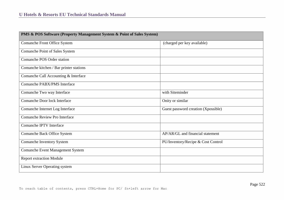
U Hotels & Resorts EU Technical Standards Manual
Page 522 To reach table of contents, press CTRL+Home for PC/ fn+left arrow for Mac
PMS & POS Software (Property Management System & Point of Sales System)
Comanche Front Office System (charged per key available)
Comanche Point of Sales System
Comanche POS Order station
Comanche kitchen / Bar printer stations
Comanche Call Accounting & Interface
Comanche PABX/PMS Interface
Comanche Two way Interface with Siteminder
Comanche Door lock Interface Onity or similar
Comanche Internet Log Interface Guest password creation (Xpossible)
Comanche Review Pro Interface
Comanche IPTV Interface
Comanche Back Office System AP/AR/GL and financial statement
Comanche Inventory System PU/Inventory/Recipe & Cost Control
Comanche Event Management System
Report extraction Module
Linux Server Operating system

U Hotels & Resorts EU Technical Standards Manual
Page 523 To reach table of contents, press CTRL+Home for PC/ fn+left arrow for Mac
Server Rack

U Hotels & Resorts EU Technical Standards Manual
Page 524 To reach table of contents, press CTRL+Home for PC/ fn+left arrow for Mac

U Hotels & Resorts EU Technical Standards Manual
Page 525 To reach table of contents, press CTRL+Home for PC/ fn+left arrow for Mac
Cabling schematic from Computer Room to Floor Switch and to Guest Room for standard configuration (Guest Network MUST be physically separate
from Back of House network for security reasons)
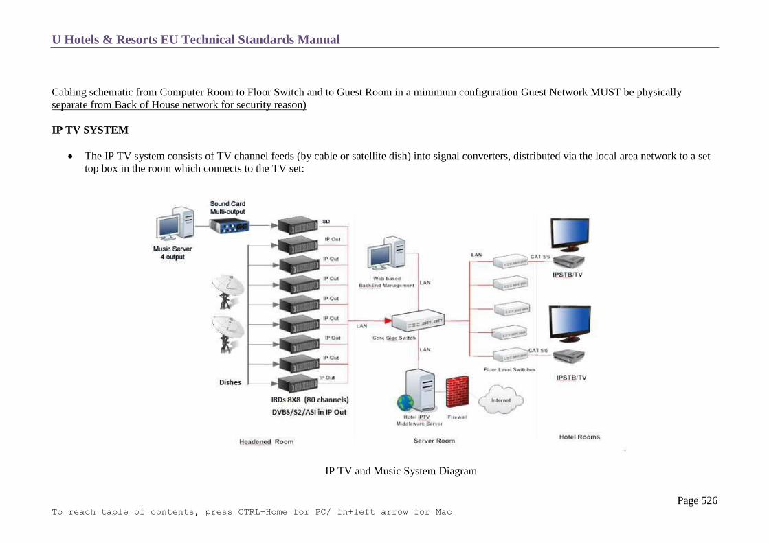
U Hotels & Resorts EU Technical Standards Manual
Page 526 To reach table of contents, press CTRL+Home for PC/ fn+left arrow for Mac
Cabling schematic from Computer Room to Floor Switch and to Guest Room in a minimum configuration Guest Network MUST be physically
separate from Back of House network for security reason)
IP TV SYSTEM
The IP TV system consists of TV channel feeds (by cable or satellite dish) into signal converters, distributed via the local area network to a set
top box in the room which connects to the TV set:
IP TV and Music System Diagram

U Hotels & Resorts EU Technical Standards Manual
Page 527 To reach table of contents, press CTRL+Home for PC/ fn+left arrow for Mac
UHR information channel is required to be a landing page when TV is turned on in all guestrooms.

U Hotels & Resorts EU Technical Standards Manual
Page 528 To reach table of contents, press CTRL+Home for PC/ fn+left arrow for Mac
Addendum
Comanche International Configuration Shell
Hotel Description EXAMPLE data:
Hotel Name : Eastin Grand Hotel Sathorn Bangkok Company Name : BTS Assets Co., Ltd. Address: 14/F, TST Tower, 21 Vibhavadi-Rangsit Road, Chomphon, Chatuchak, Bangkok 10900 Thailand Tel: +66 (0) 2 2108100 Fax: +66 (0) 2 2108399 Floor Qty: 32 floors Room Qty: 390 rooms Billing Address: BTS Assets Co., Ltd. 33/1 South Sathorn Road, Yannawa, Sathorn, Bangkok 10120 Tax ID: 3 1014 8040 5 Hotel Logo: Please see separate attached file
Floor Plan Please see separate attached file

U Hotels & Resorts EU Technical Standards Manual
Page 529 To reach table of contents, press CTRL+Home for PC/ fn+left arrow for Mac
AUTOMATIC WAKE – UP CALL FUNCTION
General
A program on the hotel PABX should allow programming of automatic wake-up calls at the times required (see chapter T 13 Telephone,
paragraph on Hotel PABX functions).
Programming of wake-up calls should be possible from the reception, by the concierge and the phone operators; the same PBX program should
enable simultaneous wake-up calls to be made to several guests, for example for group departures.
Operation
It must be possible to print out the information on a printer, with indication of the time programmed, guestroom number and wake-up time.
Modifications or cancellations must be possible, with modifications also being printed via a printer.
It must be possible to check the programmed wake-up time at any time.
Wake-up messages should be received via telephone sets, with a rapid ringing sequence, with a second call after a few minutes if the guest does
not pick up the phone following the first call.
The wake-up time, and acknowledgment of receipt of the call when the guest’s handset is picked up, should also be stored and printed via a
printer.
Guest Room Alarm Clock
Guest room alarm clocks are independent individual alarm clocks placed on or flush-mounted in the main bedside table (see chapter C-2 Rooms
paragraph on fittings)
The appearance and exact dimensions should be the decision of the interior designer.
The alarm clock system should be on a 24 hour basis, and the mechanism should have a silent movement.
Wake-up should be programmed by turning a button. Commands should be validated by pressing a switch and a dim indicator light should
come on.
Cancellation or modification of the programmed times must be possible.
Digital clock (Depending on Hotel Program)
In some countries, a digital clock may be incorporated into the television set with adjustable brightness and alarm clock function.
U Hotels & Resorts EU Technical Standards Manual
Page 530 To reach table of contents, press CTRL+Home for PC/ fn+left arrow for Mac
In-House Communications (replaces paging)
General:
The most common tool used is a mobile phone with GSM (Global System for Mobile Communications) standards. Local providers will have
deck phone or offer packages which cover the entire hotel.
System:
Indoor coverage is also supported by GSM and may be achieved by using an indoor picocell base station, or an indoor repeater with distributed
indoor antennas fed through power splitters to deliver the radio signals from an antenna outdoors to the separate indoor distributed antenna
system. These are typically deployed when a lot of call capacity is needed indoors. However, this is not a prerequisite, since indoor coverage is
also provided by in-building penetration of the radio signals from any nearby cell.
Users:
Subscriber Identity Module (SIM)
One of the key features of GSM is the Subscriber Identity Module, commonly known as a SIM card. The SIM is a detachable smart card
containing the user's subscription information and phone book.
Depending on package some operators will block this just for internal hotel use by allowing the phone to use only a single SIM, or only a SIM
issued by them; this practice is known as SIM locking.

U Hotels & Resorts EU Technical Standards Manual
Page 531 To reach table of contents, press CTRL+Home for PC/ fn+left arrow for Mac
TELEPHONE
Characteristics of PABX
Electrical Power Supply
Alarms
PABX Capacity
Internal Processor
Classes of Service
Attendant Consoles
PABX Hotel Functions
Interface
Dedicated Lines
Connection Cables
Telephone Outlets
Numbering Plan
Billing
Administration and Services Telephone Sets
Guest Services Telephone Sets with Display
Guest Room Telephone Sets

U Hotels & Resorts EU Technical Standards Manual
Page 532 To reach table of contents, press CTRL+Home for PC/ fn+left arrow for Mac
CHARACTERISTICS OF PABX
The PABX is of the digital technology electronic switching type, with direct connection to the public network.
Equipment is accessed from the front panel. The back panel primarily contains fixed wiring and remains accessible.
The PABX must have an ambient temperature operating range between + 15˚ and 30˚C and a relative humidity rating of up to 80%. It must be
able to withstand temperature changes of + 10˚C per hour and changes in relative humidity of + 10% per hour.
ELECTRICITY POWER SUPPLY
The electrical power supply is connected to the backup power supply.
It consists of two rectifiers (minimum), one output cabinet and batteries which give the installation an operating time of 8 hours minimum.
The batteries are installed in buffer configuration with the chargers to avoid micro cut-offs.
All elements comprising the telephone installation and peripherals (printers, streamers, display screen, etc.) must function without cut-off in the
event of a mains power failure. All these elements are also connected to the backup power supply with an inverter.

U Hotels & Resorts EU Technical Standards Manual
Page 533 To reach table of contents, press CTRL+Home for PC/ fn+left arrow for Mac
ALARMS
A system of technical alarms is connected to the BCS (see T14), with repeat signals at the telephone switchboard.
These alarms signal the following failures:
o no mains power supply at rectifier
o no 48V current output from rectifier
o abnormally high or low battery voltage
o inverter anomaly
o operating fault affecting PBX/Property management System interface
A printer also prints out a fault report.
PABX CAPACITY
The connection to the public telephone network will be either using individual analogue lines.
When individual lines are used their total number will be:
Total outside (trunk) lines: 0.3 × no. of room-modules + 15
Total internal extensions: 3.5 × number of room-modules + 15% spare capacity
Attendant consoles: number of trunk lines (rounded off to highest number)
40

U Hotels & Resorts EU Technical Standards Manual
Page 534 To reach table of contents, press CTRL+Home for PC/ fn+left arrow for Mac
INTERNAL PROCESSOR
The PABX is a stored-program type.
The program must be able to adapt to the specific needs of the hotel during operation.
In the event of a failure, the processor must automatically reload to restore 100% normal traffic.
CLASSES OF SERVICE
All fax, modem and/or internet lines included in the above extension total shall be of the analogue type.
The Guestrooms Ethernet computer lines are not included in the above number, as they function separately from the telephone network system.
(See T13).
Each extension can be assigned one of the following classes of service:
o internal extension (internal traffic only)
o controlled access (access to incoming calls only or via switchboard)
o local or regional access only
o unrestricted access (international)
Extensions can be switched at night to other service categories or the class of service may be changed at pre-programmed times.

U Hotels & Resorts EU Technical Standards Manual
Page 535 To reach table of contents, press CTRL+Home for PC/ fn+left arrow for Mac
ATTENDANT CONSOLES
Each attendant console can be used independently. The circuits are sized to enable an attendant to process at least five calls simultaneously.
The standard features and functions are available:
o placing of outside or internal call on hold with programmable music-on-hold
o transfer of a call between attendant consoles
o automatic transfer of outside call to busy extension (camp-on) with music-on-hold and programmable message with possible
reconnection to outside call (recovery)
o signalling of waiting calls and room service signalling
o signalling of internal extension called
o signalling of calling extension (at the switchboard, and also at the room service, housekeeper, front desk, concierge, valet)
o trunk line reservation

U Hotels & Resorts EU Technical Standards Manual
Page 536 To reach table of contents, press CTRL+Home for PC/ fn+left arrow for Mac
PABX HOTEL FUNCTIONS
The PABX should offer all or most of the following hotel functions:
Night forwarding
Night service
Voice prompts
Internal directory
Abbreviated dialling (single digit)
Voice mail
Message waiting signal
Check in /check out
Room status
Automatic wake-up call (including groups).
VIP code
Conference calls
Feature package transfer
Direct inward dialling
Do Not Disturb
Prepayment
Call parking
Group management
Remote maintenance system

U Hotels & Resorts EU Technical Standards Manual
Page 537 To reach table of contents, press CTRL+Home for PC/ fn+left arrow for Mac
INTERFACE
The interface between the Property Management System and the PABX carries the following information:
o billing information
o two-way information on check in / checkout and room status information
o direct inward dialling information for rooms and meeting room extensions
o guest room directory information
o automatic wakeup information.
Guest directory information is entered via the Property Management System.
The Property Management System receives or exchanges data with the PABX on a step-by step basis. The data is stored in both the PABX and
the PMS.
DEDICATED LINES
Access to advanced technologies and efficient maintenance services, dedicated line provisions comprise the following:
o connection to the PABX main distribution frame
o a dedicated line in the BCS control room, connected to the fire department
o a dedicated line in the PABX room, for remote maintenance of the switchboard
o a dedicated line in the reservations office, for remote maintenance of the electronic key system
o 43dedicated lines in the computer room for remote maintenance of IT system (PMS, points of sale, office systems).
The number of dedicated lines required shall be specified by U Hotels and Resorts Management with a technical consultant specialist.

U Hotels & Resorts EU Technical Standards Manual
Page 538 To reach table of contents, press CTRL+Home for PC/ fn+left arrow for Mac
CONNECTION CABLES
All individual distribution and connections shall be done through a structured cabling system, as described in chapter T14, section1. This will
be rated CAT 6, so that all lines can be reprogrammed for other uses, such as data transmission throughout the whole building.
TELEPHONE OUTLETS
Telephone outlets in all areas must be fitted with international type plugs (ISO = RJ 45), with the same rating as the structured cabling used
(Cat 6).
The outlets used and their connections, will offer the possibility to divide an RJ 45 plug into several units (such as INFRA + duplicators).
In service areas and guestrooms it must be impossible to remove the telephone sets from the outlets without special tooling.

U Hotels & Resorts EU Technical Standards Manual
Page 539 To reach table of contents, press CTRL+Home for PC/ fn+left arrow for Mac
NUMBERING PLAN
The numbering plan is adapted to the hotel to make the extension number correspond to the guestroom and floor number (functional
numbering).
Internal numbering uses three to five digits (1 prefix + 2 to 4 digits).
Dialling without a prefix is possible using time-outs.
BILLING
Billing encompasses the following:
o the programmable billing system, which interfaces with the Property Management System.
o billing management from a terminal + printer in the switchboard room.
o a pulse generator (if the local network does not generate pulse).
The centralized billing system must enable display and printout of billing information (billing units ) for:
o outgoing lines (trunk lines)
o direct inward dialling lines (DID)
o individual services (departments)
o internal extensions with breakdown by service/department
o unassigned billing units
o attendant billing units
The system must enable step-by step printout (on the switchboard printer) of the following information:
o internal calling extension
o outside number dialled
o date and time of call
o call duration
o number of billing pulses for the call
o call mode used
o call charges

U Hotels & Resorts EU Technical Standards Manual
Page 540 To reach table of contents, press CTRL+Home for PC/ fn+left arrow for Mac
ADMINISTRATION AND SERVICES TELEPHONE SETS
The telephone sets used must offer the following features:
programmable fixed and delayed call forwarding
variable call forwarding
camp-on busy extension with call waiting signal on called extension
grouped lines (“hunting groups”) with pre-set or variable call routing
three-way conferencing including 1 trunk line party
off-hook dialling (“hot line”) or automatic call to pre-programmed number
password controlled extension barring
storing of last external number dialled.

U Hotels & Resorts EU Technical Standards Manual
Page 541 To reach table of contents, press CTRL+Home for PC/ fn+left arrow for Mac
GUEST SERVICES TELEPHONE SETS WITH DISPLAY
These sets have an LCD display which shows the calling room number, guest name, language and status.
This information is entered via the Property Management System; dialogue between the PABX and the PMS computer makes any further data
entry unnecessary.
Simultaneous calls are handled on multi line sets or by extension groups
These telephone sets have a memory for recording of calls which are not immediately answered. The caller receives a recorded message stating
that the call has been recorded and will be returned as soon as possible. Message waiting notification is transmitted to the person who was
unable to answer the call.
This type of telephone is used by the housekeeper, room service, laundry, concierge, front desk, bellboy, restaurants, and health club and
business centre.
GUEST ROOM TELEPHONE SETS
The guest rooms are equipped with two telephone lines. A wall mounted set with off-hook connection in the bathroom is connected to the same
line modem as the telephones in the room, one on the night table.
For suites with three sets, adjustable ring tones are provided for the room extensions and the living room extensions.
The sets do not have a message waiting features as they tend to be of an antique design.

U Hotels & Resorts EU Technical Standards Manual
Page 542 To reach table of contents, press CTRL+Home for PC/ fn+left arrow for Mac
ELEVATORS (LIFTS)
General
Typical Equipment
Guest Elevators
Service Elevators
Escalators
Cleaning Cradles
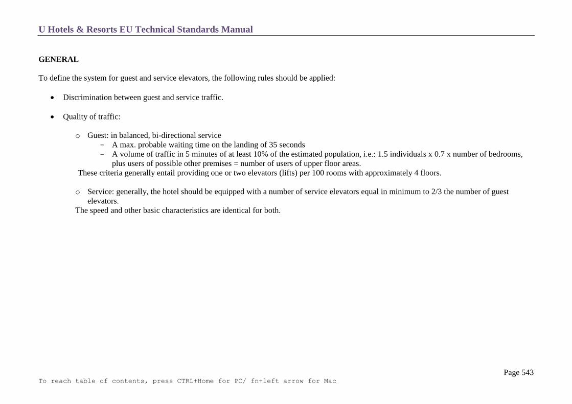
U Hotels & Resorts EU Technical Standards Manual
Page 543 To reach table of contents, press CTRL+Home for PC/ fn+left arrow for Mac
GENERAL
To define the system for guest and service elevators, the following rules should be applied:
Discrimination between guest and service traffic.
Quality of traffic:
o Guest: in balanced, bi-directional service
A max. probable waiting time on the landing of 35 seconds
A volume of traffic in 5 minutes of at least 10% of the estimated population, i.e.: 1.5 individuals x 0.7 x number of bedrooms,
plus users of possible other premises = number of users of upper floor areas.
These criteria generally entail providing one or two elevators (lifts) per 100 rooms with approximately 4 floors.
o Service: generally, the hotel should be equipped with a number of service elevators equal in minimum to 2/3 the number of guest
elevators.
The speed and other basic characteristics are identical for both.

U Hotels & Resorts EU Technical Standards Manual
Page 544 To reach table of contents, press CTRL+Home for PC/ fn+left arrow for Mac
TYPICAL EQUIPMENT
The following gives the equipment corresponding to the traffic criteria.
It allows anticipating equipment based on an initial approximation.
This choice has to be validated by a precise study adapted to each project, taking into account particularly special traffic.
In some cases, it is anticipated to make a choice:
o Regarding the number of cabins, to take into account the type of hotel:
resort
business
o Regarding the speed, following the number of hotel floors

U Hotels & Resorts EU Technical Standards Manual
Page 545 To reach table of contents, press CTRL+Home for PC/ fn+left arrow for Mac
GUEST ELEVATORS
Car
The metallic car is composed of:
A bearing frame with support structure, guides and parachute
A noise protected platform. The noise protection is made by rubber pads between the frame and the platform structure. This structure is covered
by a minimum 60 mm thick wood (oak) deck. The top floor covering is required in hard material, such as mat, adapted carpet or marble.
A right angle shaped metallic cabin made of stiffened (or ribbed) panels no connected to the bearing frame. This box is clad with removable
decorative panels resistant to graffiti.
An emergency hatch.
A ceiling made of ribbed panels supporting a decorative false ceiling, including the lighting fixtures (150 lux) and a battery-powered
emergency lighting.
Accessories:
o stainless steel or brass hand bar
o loud speaker connected to the central sound system (for announcement only)
o telephone connected by simple off hooking to BCS control room
o electronic promotional panel for points of sale
o maximum authorized load indication and regulation panel, where applicable
This cabin is decorated by the interior designer in harmony with the decoration of premises and public passageways.
Sliding Doors
The landing and cabin doors will be sliding central opening type, in double-face box structure and soundproofed.
The opening and the closing of the cabin/landing doors will be synchronized and automatically controlled.
The cabin doors will have an electronic detector, detecting from a distance the presence of an obstacle which will cause the door to reopen.
The detection limits the movement of the doors to a minimum and in particular cuts out any unnecessary reopening.
When the closing of the doors is prevented for an abnormal time, the detection becomes inoperative and the doors are closed at a reduced speed
with an audible signal warning passengers.

U Hotels & Resorts EU Technical Standards Manual
Page 546 To reach table of contents, press CTRL+Home for PC/ fn+left arrow for Mac
The door opening is never less than 90 cm.
When the cabin is moving, the cabin door and the landing door of the stop level begin their movement of opening during the approach of the
cabin to the self-levelling zone.
Inside and outside finishes: decorative materials resistant to graffiti to be specified by the interior designer. (No paint or brushed or polished
metal).
Manoeuvring
The cars are equipped with a selective collective up/down manoeuvre.
In the case of a full load, a “non-stop” device cancels the landing calls.
All elevators are equipped with a mechanical braking device, functioning automatically in case of excessive speed.
A permanent validity control has to delete automatically all calls when the number of call orders recorded in the cabin is significantly higher
than the passengers it contains.
At rest, at least one elevator stays at the lobby floor level with the doors open.
The equipment includes:
o A car button box with:
luminous buttons per floor served
one off-switch, in parallel with the alarm bell
an alarm button connected to the safety control panel in the control room (with battery)
key control (lift boy service)
A luminous and audible car position indicator in each cabin, at the lobby level and at the other public levels, with illuminated figures indicating
the level on which the car is stopped or the level on which the car is passing.
Landing boxes
o to intermediate landings: luminous buttons to go up or down 1 chime signalling the arrival of a cabin
o to the end landings: one luminous button 1 chime signalling the arrival of a cabin
In case of fire or power failure, see chapter T-10 Fire Detection Section 11 (Automatic-controls System), and chapter T-112 Electricity, Section
7 (Emergency Generators).
All lifts must come to the ground floor during a general fire alarm and can only be command override by a fireman switch.
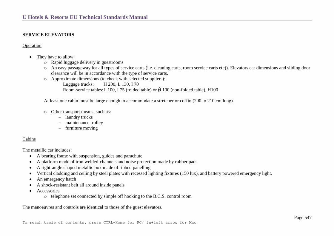
U Hotels & Resorts EU Technical Standards Manual
Page 547 To reach table of contents, press CTRL+Home for PC/ fn+left arrow for Mac
SERVICE ELEVATORS
Operation
They have to allow:
o Rapid luggage delivery in guestrooms
o An easy passageway for all types of service carts (i.e. cleaning carts, room service carts etc)). Elevators car dimensions and sliding door
clearance will be in accordance with the type of service carts.
o Approximate dimensions (to check with selected suppliers):
Luggage trucks: H 200, L 130, I 70
Room-service tables: L 100, I 75 (folded table) or Ǿ 100 (non-folded table), H100
At least one cabin must be large enough to accommodate a stretcher or coffin (200 to 210 cm long).
o Other transport means, such as:
laundry trucks
maintenance trolley
furniture moving
Cabins
The metallic car includes:
A bearing frame with suspension, guides and parachute
A platform made of iron welded-channels and noise protection made by rubber pads.
A right-angle shaped metallic box made of ribbed panelling
Vertical cladding and ceiling by steel plates with recessed lighting fixtures (150 lux), and battery powered emergency light.
An emergency hatch
A shock-resistant belt all around inside panels
Accessories
o telephone set connected by simple off hooking to the B.C.S. control room
The manoeuvres and controls are identical to those of the guest elevators.

U Hotels & Resorts EU Technical Standards Manual
Page 548 To reach table of contents, press CTRL+Home for PC/ fn+left arrow for Mac
Machine Rooms (public and service elevators)
They shall be equipped with automatic fire-extinguishing devices (powder), as mentioned in chapter T10 (section 10).

U Hotels & Resorts EU Technical Standards Manual
Page 549 To reach table of contents, press CTRL+Home for PC/ fn+left arrow for Mac
Typical Car Arrangement

U Hotels & Resorts EU Technical Standards Manual
Page 550 To reach table of contents, press CTRL+Home for PC/ fn+left arrow for Mac

U Hotels & Resorts EU Technical Standards Manual
Page 551 To reach table of contents, press CTRL+Home for PC/ fn+left arrow for Mac
ESCALATORS
Mechanism
The support chassis is made of welded wire mesh with reinforced sections covered with steel sheeting.
The assembly is set on anti-vibration pads.
The drive mechanism installed at the head is mounted on a sliding chassis to allow easy adjustment of the pull chain motor.
The steps are made of lightweight alloy and are anti-skid and interchangeable.
Two flat steps at the top and bottom make it easy to get on and off the escalator.
Emergency Stop
The escalator is equipped with a band brake, the braking torque of which is significantly lower in the up direction than in the down direction, in
order to reduce the risk of people falling when the brake is activated.
A second safety brake makes it possible to directly act on the main shaft.
Safety Devices
The escalator is equipped with easily visible emergency stop buttons. A digital display clearly indicated the source of the shutdown and the
procedure to be followed to return the escalator to service. There is a main switch to put the escalator back into service using a key.
In addition to the emergency stop buttons, safety contacts (break in operating chains contact, separator plate contact, beginning of banister rail
contact) are provided to automatically shut down the escalator in the event of danger.

U Hotels & Resorts EU Technical Standards Manual
Page 552 To reach table of contents, press CTRL+Home for PC/ fn+left arrow for Mac
CLEANING CRADLES
Buildings with windows that cannot be cleaned from the inside should be provided with a cleaning cradle (also applicable to interior patios).
Emergency System
Emergency evacuation is obtained either by gravity, with permanent control over the down movement by a speed limiter brake or if possible
owing to the height of the building with a manual hoisting system.
Braking System
This system should provide for:
o electro-brake on the motor
o safety, jaw-type electro-brake operating automatically in case of an increase in the descending speed
o centrifugal type seen-limiter brake, operating if the first two are unlocked by permanent manual action in view of evacuation of the
cradle in case of power failure
Roof Cart
The roof cart is driven electrically and moves on rail.
The guide rollers hold the roof cart along its route along the façade.
Carrier Arms
No electrical conduits are visible along the arms.
At the base of each carrier arm, an electrical contact inhibits any raising or descending movement if the corresponding arm is not in the correct
service position.
Cradle
Built of light metal.
The floor is non-slip.
The sides are at least 1 m high and are extended up to 1.30 m by a handrail.
Protected with rubber foam on three sides.
The cradle should stop automatically at the extreme top and bottom levels

U Hotels & Resorts EU Technical Standards Manual
Page 553 To reach table of contents, press CTRL+Home for PC/ fn+left arrow for Mac
Anti – Fall System
An anti-fall system is provided via two emergency cables supporting no loads during normal operation.
Building height permitting, an individual protection device of the stop-fall type is provided.
Guidance
In the case of high-rise buildings (with a total height over 28 m), a cradle guidance system is provided on the facades of the building preventing
any horizontal movement or swaying.
Electrical Equipment
Watertight and dust-proof type, with all wiring-connections protected by a stuffing box.
All motors are protected individually against overloads and short-circuit.

U Hotels & Resorts EU Technical Standards Manual
Page 554 To reach table of contents, press CTRL+Home for PC/ fn+left arrow for Mac
FF & E (FURNITURE, FIXTURES AND EQUIPMENT)
List of Small Operating Equipment (“OPE”)
List of Operating Furniture and Fixtures
List of Furniture and Fixtures of Decorative Relevance and Fixed Decoration Items
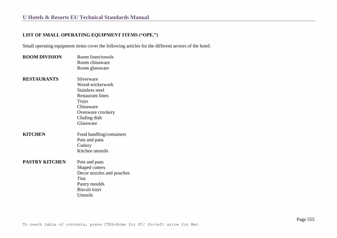
U Hotels & Resorts EU Technical Standards Manual
Page 555 To reach table of contents, press CTRL+Home for PC/ fn+left arrow for Mac
LIST OF SMALL OPERATING EQUIPMENT ITEMS (“OPE.”)
Small operating equipment items cover the following articles for the different sectors of the hotel:
ROOM DIVISION Room linen/towels
Room chinaware
Room glassware
RESTAURANTS Silverware
Wood-wickerwork
Stainless steel
Restaurant linen
Trays
Chinaware
Ovenware crockery
Chafing dish
Glassware
KITCHEN Food handling/containers
Pots and pans
Cutlery
Kitchen utensils
PASTRY KITCHEN Pots and pans
Shaped cutters
Decor nozzles and pouches
Tins
Pastry moulds
Biscuit trays
Utensils

U Hotels & Resorts EU Technical Standards Manual
Page 556 To reach table of contents, press CTRL+Home for PC/ fn+left arrow for Mac
THEME RESTAURANT
Same as the above restaurants, plus specialised:
Wood- wickerwork
Service cutlery
Cutlery
Miscellaneous
Flatware-hollowware
Chinaware
Stone-earthenware
Copperware
Cast iron utensils
Glassware
THEME KITCHENS Same as the above kitchens, plus specialised: Wood – bambooware Pots and pans Cutlery Small equipment Flat-hollowware Earthenware Utensils Copperware THEME PASTRY KITCHEN Same as the above pastry items, plus specialised moulds and biscuits trays EMPLOYEES Stainless steel Linen Trays Chinaware Glassware MEDICAL EQUIPMENT First aid Medical examination room

U Hotels & Resorts EU Technical Standards Manual
Page 557 To reach table of contents, press CTRL+Home for PC/ fn+left arrow for Mac
MAINTENANCE
All light tools and minor items of equipment needed for repair, maintenance and security tasks. This list is drawn up with reference to the
equipment and technical installation for each project.
UNIFORMS
Uniforms for all personnel whether in contact with guests or not.
Front of house uniforms be designed and implemented on a property to property basis which should be influenced by the interior design of the
property in terms of style and colour. When planning uniforms the following must always be followed and considered:
o Materials selected should be durable, comfortable and easily laundered which means the avoidance of materials requiring dry cleaning.
Common material mix would be 60-80% cotton and the remaining would be polyester.
o Materials selected should be assured to have continued stock and availability for replacement orders.
o In some cases and locations footwear will be included as part of the uniform.
ITEMS FOR SPECIFIC DIVISIONS
Defined with reference to the specific features of each project.
Depending on contractual conditions, the listing is generally produced by U Hotels and Resorts Management, in accordance with a standard
computerized program.
The basic data is:
o Casual, comfortable and locally infused.
o Maximum of 2 pieces of uniform (shirt and trousers).
o Same uniform for all front of house positions. Exceptions would be the following departments; kitchen, stewarding, engineering, pool &
fitness employees.
Corresponding to the essential features for operation and the brand image standards.
The listing is handed over by U Hotels and Resorts Management to the Owning Company.
LIST OF OPERATING FURNITURE AND FIXTURES (O.F.F E.)

U Hotels & Resorts EU Technical Standards Manual
Page 558 To reach table of contents, press CTRL+Home for PC/ fn+left arrow for Mac
The list of basic furniture and fixtures covers all movable furniture, equipment and fittings as well as the elements needed for furnishing and
good operation of the public rooms and the hotel services, in respect of which U Hotels & Resorts wishes to see adopted specific items of
equipment which meet its operating criteria and/or its image.
This list should be done in accordance with the following classification.
1. Rooms division
2. Housekeeping
3. Rooms
4. Restaurants and bars
5. Banquets
6. Administration offices
7. Back of the house and employee areas
8. Vehicles/transportation
9. Leisure facilities
They are complemented by the lists of kitchen and laundry equipment, which are drawn up by their own specific consultants ( as explained in
the introduction).
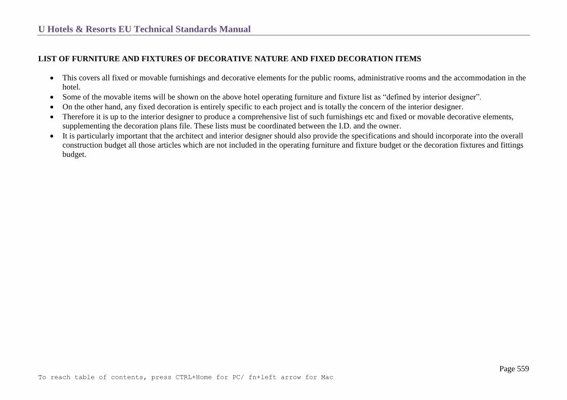
U Hotels & Resorts EU Technical Standards Manual
Page 559 To reach table of contents, press CTRL+Home for PC/ fn+left arrow for Mac
LIST OF FURNITURE AND FIXTURES OF DECORATIVE NATURE AND FIXED DECORATION ITEMS
This covers all fixed or movable furnishings and decorative elements for the public rooms, administrative rooms and the accommodation in the
hotel.
Some of the movable items will be shown on the above hotel operating furniture and fixture list as “defined by interior designer”.
On the other hand, any fixed decoration is entirely specific to each project and is totally the concern of the interior designer.
Therefore it is up to the interior designer to produce a comprehensive list of such furnishings etc and fixed or movable decorative elements,
supplementing the decoration plans file. These lists must be coordinated between the I.D. and the owner.
It is particularly important that the architect and interior designer should also provide the specifications and should incorporate into the overall
construction budget all those articles which are not included in the operating furniture and fixture budget or the decoration fixtures and fittings
budget.

U Hotels & Resorts EU Technical Standards Manual
Page 560 To reach table of contents, press CTRL+Home for PC/ fn+left arrow for Mac
SPARE PARTS
General Notes
Sanitary Plumbing
Electricity
Low Voltage Equipment
Air Conditioning
Kitchen and Laundry
Public Areas
Accommodation

U Hotels & Resorts EU Technical Standards Manual
Page 561 To reach table of contents, press CTRL+Home for PC/ fn+left arrow for Mac
GENERAL NOTES
The provision of spare parts at the time of hand-over of the hotel will be an integral part of contracts awarded to contractors.
The precise list will be specified by agreement with the different manufacturers and suppliers of equipment and fittings.
The lists below are theoretical lists given by way of example. Arrangements must be made for the necessary storage spaces for all spare parts.

U Hotels & Resorts EU Technical Standards Manual
Page 562 To reach table of contents, press CTRL+Home for PC/ fn+left arrow for Mac
SANITARY PLUMBING
Water Tanks
1 ball cock with float
1 strainer
Booster Pump
1 pressures tat
1 set of cams for permutation
1 anti-vibration collar
Distribution
Cold and hot water
o anti-hammer unit of each diameter
o automatic drain cock of each diameter
Hot water
Production by modules
o regulation thermostat
o 1 safety thermostat
o 1 automatic drain cock
o 1 manual drain cock
o 1 thermometer for the boiler chimney outlet
o 1 level monitor for water top-up
Hot water return
o 2–column base valves
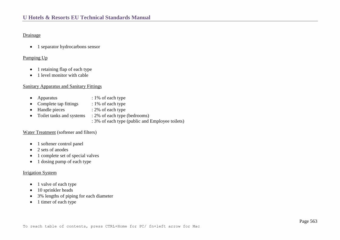
U Hotels & Resorts EU Technical Standards Manual
Page 563 To reach table of contents, press CTRL+Home for PC/ fn+left arrow for Mac
Drainage
1 separator hydrocarbons sensor
Pumping Up
1 retaining flap of each type
1 level monitor with cable
Sanitary Apparatus and Sanitary Fittings
Apparatus : 1% of each type
Complete tap fittings : 1% of each type
Handle pieces : 2% of each type
Toilet tanks and systems : 2% of each type (bedrooms)
: 3% of each type (public and Employee toilets)
Water Treatment (softener and filters)
1 softener control panel
2 sets of anodes
1 complete set of special valves
1 dosing pump of each type
Irrigation System
1 valve of each type
10 sprinkler heads
3% lengths of piping for each diameter
1 timer of each type
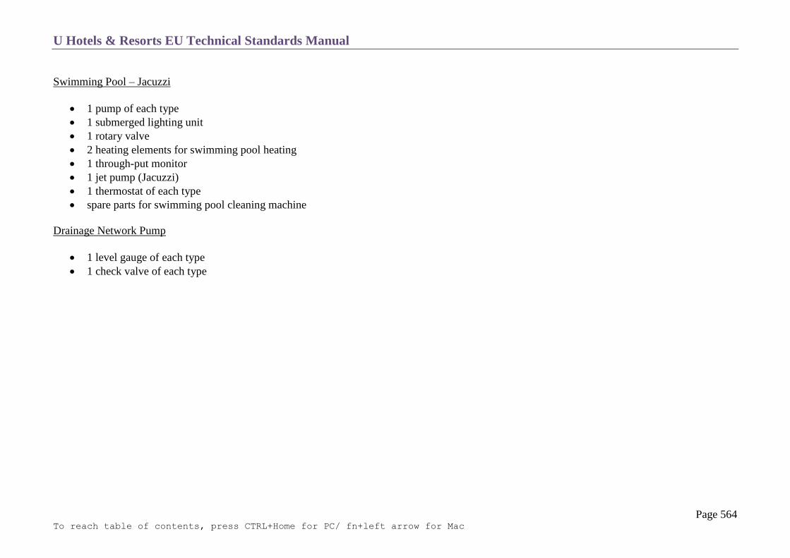
U Hotels & Resorts EU Technical Standards Manual
Page 564 To reach table of contents, press CTRL+Home for PC/ fn+left arrow for Mac
Swimming Pool – Jacuzzi
1 pump of each type
1 submerged lighting unit
1 rotary valve
2 heating elements for swimming pool heating
1 through-put monitor
1 jet pump (Jacuzzi)
1 thermostat of each type
spare parts for swimming pool cleaning machine
Drainage Network Pump
1 level gauge of each type
1 check valve of each type

U Hotels & Resorts EU Technical Standards Manual
Page 565 To reach table of contents, press CTRL+Home for PC/ fn+left arrow for Mac
ELECTRICITY
Supply and Transformer Station
1 set of fuses for high voltage cell
1 circuit breaker of each type
1 pull-out drawer of each type
set of low voltage fuses
Diesel Generating Set
2 fuel filters cartridges
2 oil filters cartridges
2 air filters cartridges
2 sets of joints for maintenance operations
General Equipment
1 set of 10 fuses of each of the calibres and types installed
1 set of the various contactors or circuit breakers used
1 complete set equal to number of indication lamps installed
5% of sockets of each type installed
5% of safety lighting blocks
5% simple, two-way and push button switches and dimmers of each type installed
5 lighting fixtures of each type installed
Switchboards, Power
2% of circuit breakers of each type
3% of contactors of each type
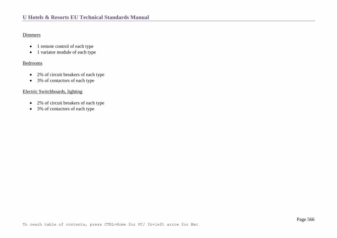
U Hotels & Resorts EU Technical Standards Manual
Page 566 To reach table of contents, press CTRL+Home for PC/ fn+left arrow for Mac
Dimmers
1 remote control of each type
1 variator module of each type
Bedrooms
2% of circuit breakers of each type
3% of contactors of each type
Electric Switchboards, lighting
2% of circuit breakers of each type
3% of contactors of each type
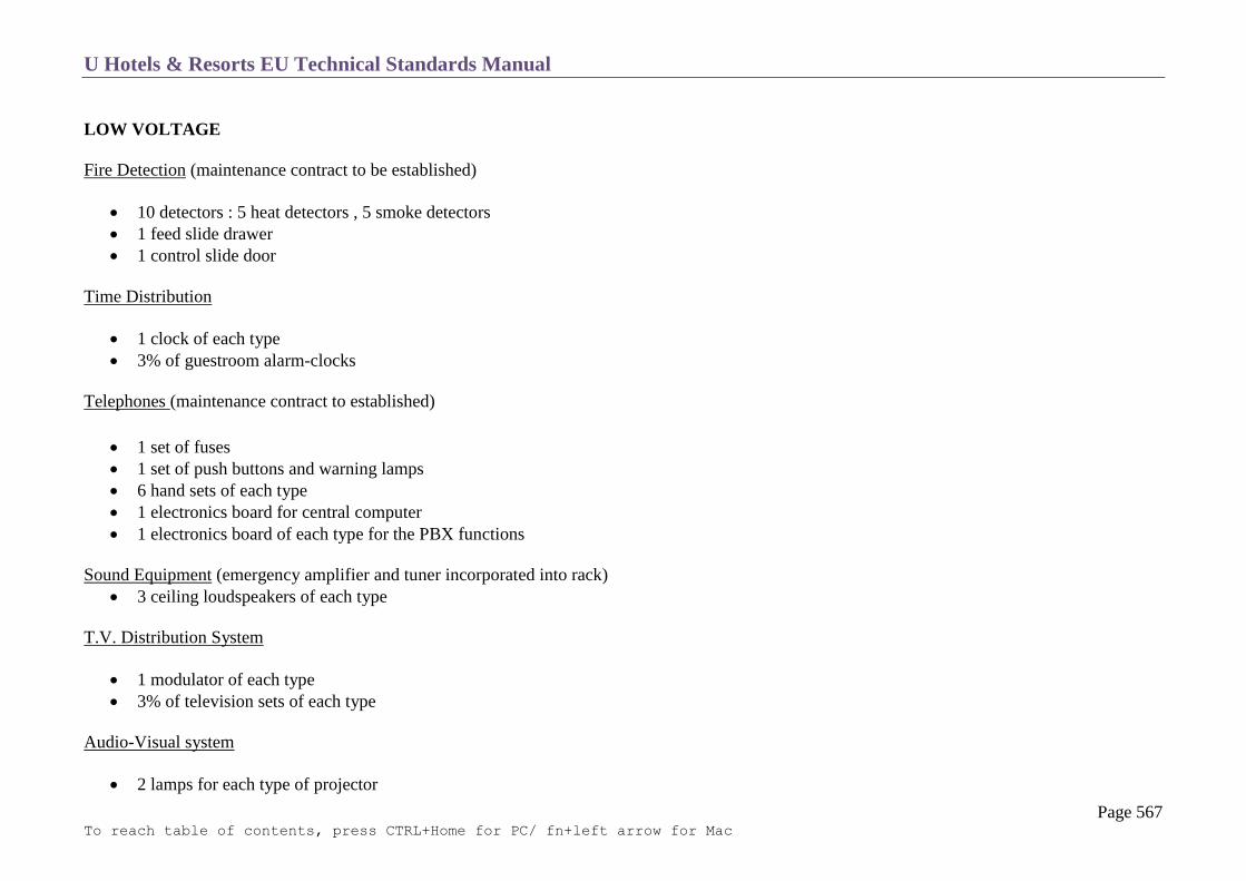
U Hotels & Resorts EU Technical Standards Manual
Page 567 To reach table of contents, press CTRL+Home for PC/ fn+left arrow for Mac
LOW VOLTAGE
Fire Detection (maintenance contract to be established)
10 detectors : 5 heat detectors , 5 smoke detectors
1 feed slide drawer
1 control slide door
Time Distribution
1 clock of each type
3% of guestroom alarm-clocks
Telephones (maintenance contract to established)
1 set of fuses
1 set of push buttons and warning lamps
6 hand sets of each type
1 electronics board for central computer
1 electronics board of each type for the PBX functions
Sound Equipment (emergency amplifier and tuner incorporated into rack)
3 ceiling loudspeakers of each type
T.V. Distribution System
1 modulator of each type
3% of television sets of each type
Audio-Visual system
2 lamps for each type of projector

U Hotels & Resorts EU Technical Standards Manual
Page 568 To reach table of contents, press CTRL+Home for PC/ fn+left arrow for Mac
1 printed circuit for motorized projectors
1 remote control
1 case for slide projector
1 sound volume switch unit
1 emergency amplifier
Safety Panels and Alarm Control
1 set of alarm lamps equal to the number of lines
5% of push buttons of each type

U Hotels & Resorts EU Technical Standards Manual
Page 569 To reach table of contents, press CTRL+Home for PC/ fn+left arrow for Mac
AIR CONDITIONING
Chilled Water Production
Pumps
o emergency pump to be installed for each type
Cooling units
o oil filter cartridges of each type
o de-humidifier cartridges of each type
Steam Boiler (1 water feed pump to be installed as back-up)
1 manometer of each type
1 thermometer of each type
1 drain sealing joints and cylinder rings for each boiler
1 steam trap of each type
Oil or Gas Burner
1 box boiler relays for each type
2 sets electrodes
2 sets nozzles
2 combustion monitoring photo-electric cells
1 gas injection crosshead for atmospheric burners
Circulation Electro Pumps
1 pump of each type
1 rotary gaskets, if required, per type of pump
Fan Motor Set
1 electronic motor per power range (minimum 5 – maximum 10)
1 set of spare belts for each fan

U Hotels & Resorts EU Technical Standards Manual
Page 570 To reach table of contents, press CTRL+Home for PC/ fn+left arrow for Mac
Valves, Fittings, Pipes
2 cocks of each diameter and each type
2 automatic drain cocks
Regulators
3-bedroom temperature thermostats
3-fan-coil regulating valves
2 thermostats, air stats of each type
2 motors and regulating valves of each type
Air Handling Unit
set of air filters for each unit
1 sensor of each type
1 differential pressure switch of each type
Extractors
1 set of grease filters for each extractor
1 set of filters for each fresh air fan
Sundries
10 fan-coil motors
1 set if filters complete for each type
10% (minimum 20) of fan-coil filters for bedrooms or individual heat pumps
10% of nozzles for air washer
5 activation coils for fire dampers and cut-off doors
5 clock face thermometers for fluid insertion
5 clock face manometers

U Hotels & Resorts EU Technical Standards Manual
Page 571 To reach table of contents, press CTRL+Home for PC/ fn+left arrow for Mac
1 set of rollers for each type of pump and fan
KITCHEN AND LAUNDRY
The list of spare parts will be produced by U Hotels and Resorts Management along with the supplier, with reference to equipment installed.
PUBLIC AREAS
10% of carpets of each type
5% of fabrics of each type
ACCOMMODATION
5% of fabrics of each type for curtains
5% of fabrics of each type for upholstery
1% furniture elements
10% carpets of each type
5% of curtain rails
1% of lighting fixtures of each type
2% of door locks
1% of floor-standing lamps
5% of wall coverings
5% of light shades of each type
1% of electrical accessories
1% of tiles
2% of corridor lighting fixtures
1% of sanitary fittings

U Hotels & Resorts EU Technical Standards Manual
Page 572 To reach table of contents, press CTRL+Home for PC/ fn+left arrow for Mac
TAKEOVER BY HOTEL OPERATOR
Maintenance Contracts
Guarantees
Insurance
As-Built Plans
U Hotels & Resorts EU Technical Standards Manual
Page 573 To reach table of contents, press CTRL+Home for PC/ fn+left arrow for Mac
MAINTENANCE CONTRACTS
All indications relating to maintenance of equipment must be mentioned in the tender documents, following which they will then be the subject
of contractual requirement to be met by the successful contractors.
For all installation work, the tendering contractors must submit with their quotation a draft maintenance contract in which they undertake to
guarantee work on the equipment requiring qualified personnel available locally (chilled water production set, heat pumps, generating sets, lift,
automatic exchange, etc.) by the manufacturer or by personnel approved by the owner and operator, for a minimum 5 year period.
The analysis of these proposals will be an element which determines the final choice of the contractors to carry out the operation.
On the other hand, the choice of equipment must take into account availability from stock of spare parts which exists locally. If there were to be
no stock, it would be necessary to add to the list of spare parts a supplementary list relating to the equipment excluded.
GUARANTEES
Any moving equipment (in particular rotating machinery) must be selected taking into account that they must provide uninterrupted service of
8,000 hours without curative maintenance. The manufacturer will have to provide a total guarantee for two years parts and labour and a
guarantee for 5 years for replacement of defective equipment. In addition, contractors must submit with their tenders:
o Diagrams and exploded view of equipment
o A precise and detailed list of the intended equipment.

U Hotels & Resorts EU Technical Standards Manual
Page 574 To reach table of contents, press CTRL+Home for PC/ fn+left arrow for Mac
INSURANCE
Prior to take-over by the hotel operators, the owning company must have taken out the insurance policies specified in the management contract.
AS – BUILT PLANS
One month before acceptance of the work, the contractor must supply a file of as – built documents for the installation actually undertaken.
Acceptance cannot be given within less than one month after hand-over of the documents.