Table of Contents Chapter No Title Page No STRUCTURAL ANALYSIS – II L T P C 3 1 0 4 OBJECTIVE This...
127
Table of Contents Chapter No Title Page No 1 Construction Planning 1.1 Basic Concepts in the Development of Construction Plans 1 1.2 Choice of Technology and Construction Method 2 1.3 Defining Work Tasks 3 1.4 Defining Precedence Relationships Among Activities 6 1.5 Estimating Activity Durations 10 1.6 Estimating Resource Requirements for Work Activities 14 1.7 Coding Systems 15 1.8 References 17 2 Fundamental Scheduling Procedures 2.1 Relevance of Construction Schedules 18 2.2 The Critical Path Method 19 2.3 Calculations for Critical Path Scheduling 20 2.4 Activity Float and Schedules 22 2.5 Presenting Project Schedules 25 2.6 Critical Path Scheduling for Activity-on-Node and with Leads, Lags, and Windows 30 2.7 Calculations for Scheduling with Leads, Lags and Windows 33 2.8 Resource Oriented Scheduling 34 2.9 Scheduling with Resource Constraints and Precedence 36 2.10 Use of Advanced Scheduling Techniques 38 2.11 Scheduling with Uncertain Durations 38 2.12 Crashing and Time/Cost Tradeoffs 42 2.13 Improving the Scheduling Process 45 2.14 References 46 3 Cost Control, Monitoring and Accounting 3.1 The Cost Control Problem 47 3.2 The Project Budget 47
-
Upload
trinhthien -
Category
Documents
-
view
213 -
download
0
Transcript of Table of Contents Chapter No Title Page No STRUCTURAL ANALYSIS – II L T P C 3 1 0 4 OBJECTIVE This...

Table of Contents
Chapter No Title Page No
1 Construction Planning
1.1 Basic Concepts in the Development of ConstructionPlans
1
1.2 Choice of Technology and Construction Method 2
1.3 Defining Work Tasks 3
1.4 Defining Precedence Relationships Among Activities 6
1.5 Estimating Activity Durations 10
1.6 Estimating Resource Requirements for Work Activities 14
1.7 Coding Systems 15
1.8 References 17
2 Fundamental Scheduling Procedures
2.1 Relevance of Construction Schedules 18
2.2 The Critical Path Method 19
2.3 Calculations for Critical Path Scheduling 20
2.4 Activity Float and Schedules 22
2.5 Presenting Project Schedules 25
2.6 Critical Path Scheduling for Activity-on-Node and withLeads, Lags, and Windows
30
2.7 Calculations for Scheduling with Leads, Lags andWindows
33
2.8 Resource Oriented Scheduling 34
2.9 Scheduling with Resource Constraints and Precedence 36
2.10 Use of Advanced Scheduling Techniques 38
2.11 Scheduling with Uncertain Durations 38
2.12 Crashing and Time/Cost Tradeoffs 42
2.13 Improving the Scheduling Process 45
2.14 References 46
3 Cost Control, Monitoring and Accounting
3.1 The Cost Control Problem 47
3.2 The Project Budget 47
3.3 Forecasting for Activity Cost Control 48
3.4 Financial Accounting Systems and Cost Accounts 49
3.5 Control of Project Cash Flows 51
3.6 Schedule Control 52
3.7 Schedule and Budget Updates 54
3.8 Relating Cost and Schedule Information 54
3.9 References 56
4 Quality Control and Safety During Construction
4.1 Quality and Safety Concerns in Construction 57
4.2 Organizing for Quality and Safety 57
4.3 Work and Material Specifications 58
4.4 Total Quality Control 59
4.5 Quality Control by Statistical Methods 61
4.6 Statistical Quality Control with Sampling by Attributes 61
4.7 Statistical Quality Control with Sampling by Variables 66
4.8 Safety 71
4.9 References 71
5 Organization and Use of Project Information
5.1 Types of Project Information73
5.2 Accuracy and Use of Information74
5.3 Computerized Organization and Use of Information 76
5.4 Organizing Information in Databases 78
5.5 Relational Model of Databases 80
5.6 Other Conceptual Models of Databases 81
5.7 Centralized Database Management Systems 84
5.8 Databases and Applications Programs 85
5.9 Information Transfer and Flow 87
5.10 References 88

CE2351 STRUCTURAL ANALYSIS – II L T P C3 1 0 4OBJECTIVEThis course is in continuation of Structural Analysis – Classical Methods. Here in advancedmethod of analysis like Matrix method and Plastic Analysis are covered. Advanced topics suchas FE method and Space Structures are covered.UNIT I FLEXIBILITY METHOD 12Equilibrium and compatibility – Determinate vs Indeterminate structures – Indeterminacy -Primary structure – Compatibility conditions – Analysis of indeterminate pin-jointed planeframes, continuous beams, rigid jointed plane frames (with redundancy restricted to two).UNIT II STIFFNESS MATRIX METHOD 12Element and global stiffness matrices – Analysis of continuous beams – Co-ordinatetransformations – Rotation matrix – Transformations of stiffness matrices, load vectors anddisplacements vectors – Analysis of pin-jointed plane frames and rigid frames( with redundancyvertical to two)UNIT III FINITE ELEMENT METHOD 12Introduction – Discretisation of a structure – Displacement functions – Truss element – Beamelement – Plane stress and plane strain - Triangular elementsUNIT IV PLASTIC ANALYSIS OF STRUCTURES 12Statically indeterminate axial problems – Beams in pure bending – Plastic moment of resistance– Plastic modulus – Shape factor – Load factor – Plastic hinge and mechanism – Plasticanalysis of indeterminate beams and frames – Upper and lower bound theoremsUNIT V SPACE AND CABLE STRUCTURES 12Analysis of Space trusses using method of tension coefficients – Beams curved in planSuspension cables – suspension bridges with two and three hinged stiffening girdersTOTAL: 60 PERIODS53TEXT BOOKS1. Vaidyanathan, R. and Perumal, P., “Comprehensive structural Analysis – Vol. I & II”, LaxmiPublications, New Delhi, 20032. L.S. Negi & R.S. Jangid, “Structural Analysis”, Tata McGraw-Hill Publications, New Delhi,2003.3. BhaviKatti, S.S, “Structural Analysis – Vol. 1 Vol. 2”, Vikas Publishing House Pvt. Ltd., NewDelhi, 2008REFERENCES1. Ghali.A, Nebille,A.M. and Brown,T.G. “Structural Analysis” A unified classical and Matrixapproach” –5th edition. Spon Press, London and New York, 2003.2. Coates R.C, Coutie M.G. and Kong F.K., “Structural Analysis”, ELBS and Nelson, 19903. Structural Analysis – A Matrix Approach – G.S. Pandit & S.P. Gupta, Tata McGraw Hill2004.4. Matrix Analysis of Framed Structures – Jr. William Weaver & James M. Gere, CBSPublishers and Distributors, Delhi.

CE2351 Structural Analysis II
SCE 1 Dept of Civil
CHAPTER 1
FLEXIBILITY METHOD
Equilibrium and compatibility – Determinate vs Indeterminate structures –Indeterminacy -Primary structure – Compatibility conditions – Analysis of indeterminatepin-jointed planeframes, continuous beams, rigid jointed plane frames (with redundancyrestricted to two).
1.1 INTRODUCTION
These are the two basic methods by which an indeterminate skeletal structure isanalyzed. In these methods flexibility and stiffness properties of members are employed.These methods have been developed in conventional and matrix forms. Here conventionalmethods are discussed.
Thegivenindeterminatestructureisfirstmadestaticallydeterminatebyintroducingsuitable numberof releases. The number of releases required is equal tostaticalindeterminacy∝s. Introductionofreleasesresultsindisplacementdiscontinuitiesatthesereleases under the externally applied loads. Pairsofunknown biactions(forcesandmoments)areappliedatthesereleasesinordertorestorethecontinuityorcompatibility ofstructure.
The computation of these unknown biactions involves solution of linearsimultaneousequations.Thenumberoftheseequationsisequaltostaticalindeterminacy∝s.Aftertheunknownbiactionsarecomputedalltheinternalforcescanbecomputedintheentirestructureusingequationsofequilibriumandfreebodiesofmembers.Therequired displacements can also be computed using methods ofdisplacement computation.
Inflexibilitymethodsinceunknownsareforces atthereleasesthemethodisalsocalledforce method.Since computation of displacement is also required at releases forimposing conditions of compatibility the method is also called compatibility method. Incomputationofdisplacementsuseismadeof flexibilityproperties,hence,themethodis alsocalled flexibility method.
1.2 EQUILIBRIUM and COMPATABILITY CONDITIONS
Thethreeconditionsofequilibriumarethesumofhorizontalforces,verticalforcesandmoments at anyjoint should beequal to zero.
i.e.∑H=0;∑V=0;∑M=0Forces should be in equilibrium
i.e.∑FX=0;∑FY=0;∑FZ=0i.e.∑MX=0;∑MY=0;∑MZ=0
Displacement of a structure should be compatableThe compatibility conditions for the supports can be given as1.Roller Support δV=02.Hinged Support δV=0, δH=03.Fixed Support δV=0, δH=0, δө=0

CE2351 Structural Analysis II
SCE 2 Dept of Civil
1.3.DETERMINATE AND INDETERMINATE STRUCTURAL SYSTEMS
Ifskeletalstructureissubjectedtograduallyincreasingloads,withoutdistortingtheinitialgeometryofstructure,thatis,causingsmalldisplacements,thestructureissaidto be stable.Dynamic loads and buckling or instability of structural system are notconsideredhere.Ifforthestablestructureitispossibletofindtheinternalforcesinall the membersconstituting the structure and supporting reactions at all the supports providedfromstaticallyequationsofequilibrium only,thestructureissaidtobe determinate.
Ifitispossibletodetermineallthesupport reactionsfromequationsof equilibriumalonethestructureissaidtobeexternallydeterminateelseexternally indeterminate.If structureisexternallydeterminatebutitisnotpossible todetermineallinternalforcesthenstructureissaidtobe internallyindeterminate. Thereforeastructuralsystemmaybe:
(1)Externally indeterminate but internally determinate(2)Externally determinate but internally indeterminate(3)Externallyand internallyindeterminate(4)Externally and internallydeterminate
1.3.1.DETERMINATEVs INDETERMINATESTRUCTURES.
Determinatestructurescanbesolvingusingconditionsofequilibriumalone(∑H=0;∑V=0;∑M=0). No otherconditions arerequired.
Indeterminatestructurescannotbesolvedusingconditionsofequilibriumbecause(∑H≠0;∑V≠0;∑M≠0).Additionalconditionsarerequiredforsolvingsuchstructures.Usuallymatrixmethods areadopted.
1.4 INDETERMINACYOF STRUCTURAL SYSTEMThe indeterminacy of a structure is measured as statically (∝s) or kinematical
(∝k)Indeterminacy.∝s= P (M – N + 1) – r = PR– r ∝k= P (N – 1) + r – s+∝k= PM –cP = 6 for space frames subjected to general loadingP = 3 for plane frames subjected to inplane or normal to plane loading.N = Numberof nodes in structural system.M=Numberofmembersofcompletelystiffstructurewhichincludesfoundationassinglyconnectedsystem ofmembers.
Incompletelystiffstructurethereisnorelease present.Insinglyconnectedsystemofrigidfoundationmembersthereisonlyoneroutebetweenanytwopointsinwhichtracksarenotretraced. Thesystemisconsidered comprising ofclosed rings or loops.R = Numberof loops or rings in completely stiff structure.r = Number of releases in the system.c = Number of constraints in the system.R = (M – N + 1)

CE2351 Structural Analysis II
SCE 3 Dept of Civil
For plane and space trusses∝sreducesto:∝s=M- (NDOF)N+ PM= Number ofmembers in completely stifftruss.P = 6 and 3 for space and plane trussrespectively
N= Number of nodes in truss.NDOF = Degrees of freedomat node which is 2 for plane truss and 3 for space truss.For space truss∝s=M- 3N+ 6For plane truss∝s= M- 2 N+ 3
Test for static indeterminacy of structural system
If ∝s> 0 Structure is statically indeterminate
If ∝s= 0 Structure is statically determinateand if∝s<0 Structure is a mechanism.
Itmaybenotedthatstructuremaybemechanismevenif ∝s >0ifthereleasesarepresentinsuchawaysoastocausecollapseasmechanism.Thesituationofmechanism isunacceptable.
Statically IndeterminacyItisdifferenceoftheunknownforces(internalforcesplusexternalreactions)andthe
equations of equilibrium.Kinematic Indeterminacy
Itisthenumberofpossiblerelativedisplacementsofthenodesinthedirectionsofstressresultants.
1.5 PRIMARY STRUCTUREAstructure formed bythe removingthe excess orredundant restraints froman
indeterminatestructuremakingit staticallydeterminateis called primarystructure. This isrequired forsolvingindeterminatestructures byflexibilitymatrixmethod.
Indeterminatestructure PrimaryStructure

SCE 4 Dept of Civil
1.6.ANALYSIS OF INDETERMINATE STRUCTURES :BEAMS
1.6.1Introduction
Solvestaticallyindeterminate beams of degree more than one. Tosolvetheprobleminmatrixnotation. Tocomputereactionsatallthesupports. To compute internal resisting bending moment at any section of the
continuousbeam.Beamswhicharestaticallyindeterminatetofirstdegree,wereconsidered. If the structure isstatically indeterminate to a degree more than one, then the approach presented in theforce method is suitable.
Problem 1.1Calculate the support reactions in the continuous beam ABC due to loading as shown inFig.1.1 Assume EI to be constant throughout.
Fig 1.1
Fig 1.2
Select two reactions vise, at B(R1 ) and C(R2 ) as redundant, since the given beamisstatically indeterminate to second degree. In this case the primary structure is a cantileverbeam AC.The primary structure with a given loading is shown in Fig. 1.2
In the present case, the deflections (Δ L)1 and (Δ L) 2 of the released structure at B and Ccan be readily calculated by moment-area method. Thus
SCE 5 Dept of Civil
(Δ L) 1 = − 819.16 / EI
(Δ L) 2 = − 2311.875/ EI (1)
Forthepresentproblemthe flexibility matrix is,
a11= 125/3EI ,a21= 625/6EI
a12= 625/6EI , a22 = 1000/3EI (2)
In the actual problem the displacements atBandCare zero. Thus thecompatibility conditions for the problem may be written as,
a11 R1+ a12 R2 + (Δ L) 1 = 0
a21 R1+ a22 R2+ (Δ L) 2 = 0(3)
Substituting the value of E and I in the above equation,
R1 = 10.609 KN and R2 = 3.620 KN
Using equations of static equilibrium, R3 = 0.771 KN m and R4 = −0.755KN m
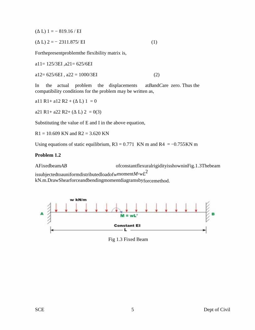
Problem 1.2
AFixedbeamAB ofconstantflexuralrigidityisshowninFig.1.3Thebeam
issubjectedtoauniformdistributedloadofwmomentM=wL2
kN.m.DrawShearforceandbendingmomentdiagramsbyforcemethod.
Fig 1.3 Fixed Beam

SCE 6 Dept of Civil
1 )
Fig 1.3 Fixed Beam with R1 and R2 as Redundant
Select vertical reaction(R1)and the support moment(R2) at B as the
redundant.Theprimarystructureinthiscaseisacantileverbeamwhichcouldbeobtainedbyreleasingtheredundant R1 andR2.
TheR1 isassumedto
positive in the upward direction andR2 is assumed to be positive in the
counterclockwisedirection.Now,calculatedeflectionat B duetoonlyappliedloading.Let (ΔL )bethetransversedeflectionat B and(ΔL 2 betheslopeatB
duetoexternalloading.Thepositivedirectionsoftheselectedredundantare showninFig.8.3b.
Fig 1.4 Primary Structure with external loading
Fig 1.5 Primary Structure with unit load along R1

SCE 7 Dept of Civil
Fig 1.6 Primary Structure with unit Moment along R2
Fig 1.7 Reaction
Fig1.8.Bending Moment Diagram
Fig1.9.Shear Force Diagram
The deflection(Δ L1)and(Δ L2)of the released structure can be evaluated from unit loadmethod. Thus,
(Δ L1) =wL4/8EI – 3wL4/8EI = −wL4/2EI (1)(Δ L2) = wL3/6EI – wL3 /2EI = − 2wL3/3EI (2)

SCE 8 Dept of Civil
1The negativesign indicates that (ΔL)isdownwards and rotation(ΔL2)is
clockwise.
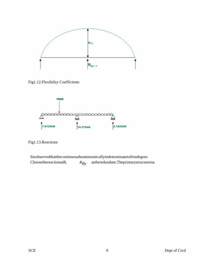
Problem 1.3.A continuous beam ABC is carrying a uniformly distributed loadof 1 kN/m in addition
toaconcentratedloadof10kNasshowninFig.7.5a, Draw bending momentandshearforcediagram.Assume EItobeconstantforallmembers.
Fig1.10.Continuous Beam
Fig1.11.Primary Structure
SCE 9 Dept of Civil
Fig1.12.Flexibility Coefficients
Fig1.13.Reactions
Itisobservedthatthecontinuousbeamisstaticallyindeterminatetofirstdegree.ChoosethereactionatB, RBy astheredundant.Theprimarystructureisa

SCE 10 Dept of Civil
simplysupportedbeamasshowninFig.1.11.Now, compute the deflection at B, in thereleasedstructure due to uniformly distributed load and concentrated load. Thisisaccomplished by unit load method.Thus,
Δ =−2083.33−1145.84
L EI EI
Δ =−3229.17(1)
L EI
Inthenextstep,applyaunitloadatBinthedirectionofRBy(upwards)and
calculatethedeflectionat B of the following structure.Thus(seeFig.7.5c),
L3
a11 =48EI
=166.67
EI(2)
Now,deflectionatBintheprimary structure due to redundant RB is,
ΔB= 166.67
EI
×RB(3)
In theactual structure, the deflection at B is zero. Hence, thecompatibility equation may bewritten as
ΔL+ΔB=0(4)
Theothertworeactionsarecalculatedbystaticequilibriumequations(videFig.1.13)
RA =7.8125kN
RB =2.8125kN
CE2351 Structural Analysis II
SCE 11 Dept of Civil
UNIT II STIFFNESS MATRIX METHOD
Element and global stiffness matrices – Analysis of continuous beams – Co-ordinatetransformations – Rotation matrix – Transformations of stiffness matrices, load vectors anddisplacements vectors – Analysis of pin-jointed plane frames and rigid frames( with redundancyvertical to two)
2.1 INTRODUCTION
Thegivenindeterminatestructureisfirstmadekinematic allydeterminatebyintroducingconstraints atthenodes.Therequirednumberofconstraintsisequaltodegrees offreedomatthenodesthatis kinematicindeterminacy∝k.Thekinematic allydeterminatestructurecomprisesoffixedendedmembers,hence,allnodal displacementsarezero.Theseresultsinstress resultantdiscontinuitiesatthesenodesundertheactionofappliedloadsorin otherwordstheclampedjointsarenotinequilibrium.
Inordertorestoretheequilibriumofstressresultantsatthenodesthenodesareimpartedsuitableunknowndisplacements.Thenumberofsimultaneousequationsrepresentingjointequilibriumofforcesisequaltokinematicindeterminacy∝k.Solutionoftheseequationsgivesunknownnodaldisplacements.Usingstiffnesspropertiesofmembersthememberendforcesarecomputedandhencetheinternalforcesthroughoutthestructure.
Since nodal displacements are unknowns, the method is also called displacement method.Since equilibriumconditionsareappliedatthejointsthemethodisalsocalledequilibriummethod.Sincestiffness properties ofmembers areusedthemethodis alsocalledstiffnessmethod.
In the displacement method of analysis the equilibrium equations are written byexpressingtheunknownjointdisplacementsintermsofloadsby usingload-displacementrelations.Theunknownjointdisplacements(thedegreesoffreedomof thestructure)are calculated by solvingequilibriumequations.Theslope-deflection andmoment-distributionmethodswereextensively usedbeforethehigh speedcomputingera.Aftertherevolutionincomputerindustry,only directstiffnessmethodisused.
2.1.1.PROPERTIES OFTHESTIFFNESS MATRIX
Theproperties ofthestiffness matrixare: It isasymmetricmatrix Thesum of elements in anycolumn must be equal to zero. It is an unstableelementthereforethedeterminantis equal to zero.
2.2.ELEMENT AND GLOBAL STIFFNESS MATRICES
Local co ordinates
In the analysis for convenience we fix the element coordinates coincident with the memberaxis called element (or) local coordinates (coordinates defined along the individual member axis )
Global co ordinates
It is normally necessary to define a coordinate system dealing with the entire structure iscalled system on global coordinates (Common coordinate system dealing with the entire structure)

CE2351 Structural Analysis II
SCE 12 Dept of Civil
Transformationmatrix
The connectivitymatrixwhich relates theinternalforcesQ and theexternal forces R is knownas the forcetransformation matrix. Writingit in amatrixform,
{Q} =[b]{R}whereQ=member forcematrix/vector, b=forcetransformationmatrix
R = external force/loadmatrix/ vector
2.3 ANALYSIS OF CONTINUOUS BEAMS
Fig 2.1 Cantilever Beam Fig 2.2 Cantilever Beam with unit load along P1
Fig 2.3 Cantilever Beam with unit Moment along P2
Fig 2.4 Cantilever Beam with unit Displacement along U1

CE2351 Structural Analysis II
SCE 13 Dept of Civil

CE2351 Structural Analysis II
SCE 14 Dept of Civil

CE2351 Structural Analysis II
SCE 15 Dept of Civil
Fig 2.5 A Four member Truss
Fig 2.6 Kinematic ally Determinate Structures

CE2351 Structural Analysis II
SCE 16 Dept of Civil
Fig 2.7Unit Displacement along U

CE2351 Structural Analysis II
SCE 17 Dept of Civil

CE2351 Structural Analysis II
SCE 18 Dept of Civil

CE2351 Structural Analysis II
SCE 19 Dept of Civil
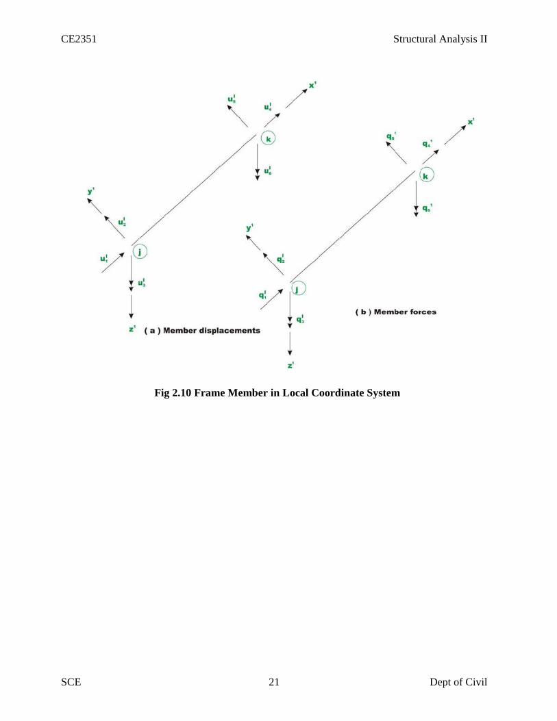
2.4.ANALYSIS OF PIN JOINTED PLANE FRAMES
An introduction to thestiffnessmethodwasgivenin thepreviouschapter.Thebasicprinciples
involvedin the analysisof beams,trusseswerediscussed.Theproblemsweresolvedwith hand
computation by thedirectapplicationofthebasicprinciples. Theprocedurediscussedin theprevious
chapterthough enlighteningarenotsuitableforcomputerprogramming.Itisnecessary to keephand
computation to aminimumwhileimplementingthisprocedureon thecomputer.
In thischaptera formalapproachhasbeen discussedwhichmay bereadily programmedon a
computer.In thislesson thedirectstiffnessmethod asapplied toplanar truss structureisdiscussed.

CE2351 Structural Analysis II
SCE 20 Dept of Civil
Planetrussesaremadeupofshortthinmembersinterconnectedathingestoformtriangulated
patterns.Ahingeconnectioncanonlytransmitforcesfromonemembertoanothermemberbutnot
themoment. For analysispurpose, thetruss is loaded atthe joints. Hence, atruss member is
subjectedtoonlyaxialforcesandtheforcesremain constant alongthelengthofthemember.The forcesin
thememberatitstwo endsmustbeof thesamemagnitudebutactin theoppositedirections for
equilibriumas shown in Fig.2.8
Fig 2.8 Truss member in Equilibrium
Fig 2.9 Force Displacement Relationship
CE2351 Structural Analysis II
SCE 21 Dept of Civil
Fig 2.10 Frame Member in Local Coordinate System

CE2351 Structural Analysis II
SCE 22 Dept of Civil
Fig 2.11Plane Frame Member in (a) Local Coordinate System (b) Global coordinate System

CE2351 Structural Analysis II
SCE 23 Dept of Civil
Fig 2.12 Rigid Frame

CE2351 Structural Analysis II
SCE 24 Dept of Civil
Fig 2.13 Node and Member Numbering
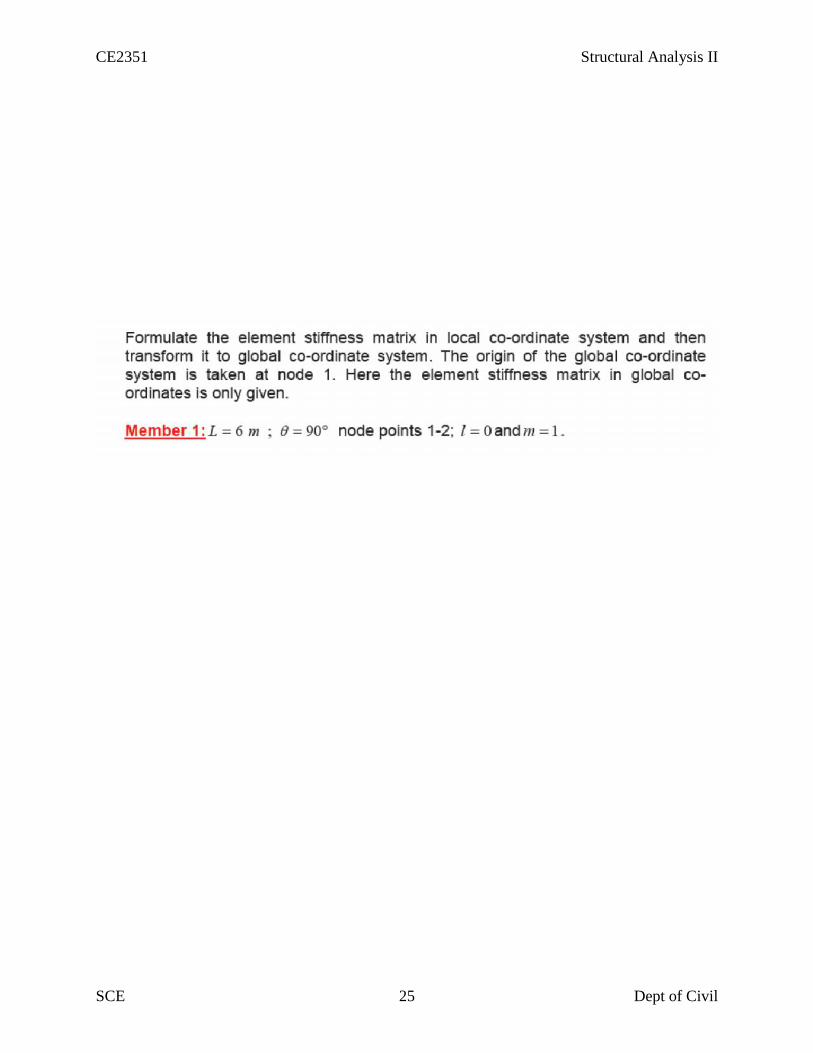
CE2351 Structural Analysis II
SCE 25 Dept of Civil

CE2351 Structural Analysis II
SCE 26 Dept of Civil

CE2351 Structural Analysis II
SCE 27 Dept of Civil
Fig 2.14 Fixed end action due to external loading in element 1 and 2
Fig 2.14 Equivalent Joint Load

CE2351 Structural Analysis II
SCE 28 Dept of Civil
Fig 2.15 Support Reactions

CE2351 Structural Analysis II
SCE 29 Dept of Civil

CE2351 Structural Analysis II
SCE 30 Dept of Civil

CE2351 Structural Analysis II
SCE 31 Dept of Civil
CHAPTER IIIFINITE ELEMENT METHOD
Introduction – Discretization of a structure – Displacement functions – Truss element –Beamelement – Plane stress and plane strain - Triangular elements
3.1.INTRODUCTION
TherearetwoversionofFEM:
1. FlexibilityMethodorForceMethod2. StiffnessMethodorDisplacementMethod. Thesetofequationsinthestiffnessmethodaretheequilibriumequationsrelatingdisplacement
sofpoints. Rayleigh-Ritzisanapproximatemethodbasedonenergyprincipleby
whichwecanobtainequilibriumequationsinmatrixform.
3.1.1 IMPORTANT DEFINITION
Nodesarepointsonthestructureatwhichdisplacementsandrotations are tobefoundorprescribed.
Element is a small domainonwhichwecan solvethe boundaryvalueproblemintermsofthedisplacementsandforcesofthe nodesonthe element.
Thediscrete representationofthe structuregeometrybyelements and nodesis called a mesh.
Theprocessofcreating a mesh(discreteentities) is called discretization.
Interpolationfunctionisakinematicallyadmissibledisplacementfunctiondefinedonanelement thatcanbeusedforinterpolatingdisplacement valuesbetweenthe nodes.
Themesh,boundaryconditions,loads,andmaterial propertiesrepresentingthe actual structureiscalled a model.
Element stiffnessmatrix relate thedisplacementstothe forcesat the elementnodes.
Globalstiffnessmatrix is anassemblyofelement stiffnessmatrix that relates thedisplacementsofthe nodesonthemeshtoappliedexternal forces.
3.1.2.StepsinFEMprocedure
1.Obtainelementstiffnessandelementloadvector.
2.Transformfromlocalorientationtoglobalorientation.
3.Assembletheglobalstiffnessmatrixandloadvector.
4.Incorporatetheexternalloads
5.Incorporatetheboundaryconditions.
6.Solvethealgebraicequationsfornodaldisplacements.
7.Obtainreactionforce,stress,internalforces,strainenergy.

CE2351 Structural Analysis II
SCE 32 Dept of Civil
8.Interpretandchecktheresults.
9.Refinemeshifnecessary,andrepeattheabovesteps.
3.2.DISCRETISATION OF STRUCTURE
Discretizationis the process of separating the length, area or volume we want to analyze intodiscrete (or separate) parts or elements.

CE2351 Structural Analysis II
SCE 33 Dept of Civil

CE2351 Structural Analysis II
SCE 34 Dept of Civil
3.3.DISPLACEMENT FUNCTIONS
The continuum is separated by imaginarylines or surfaces into a number of finite element
The elements are assumed to beconnected at discrete number of nodal points situated ontheir boundaries.
Generalized displacements are the basic unknowns. A function uniquely defines displacement field in terms of nodal displacements.
Compatibility between elements.
2D – 3D elasticity problems, displacement compatibility.
Plates and shells, displacements and their partial derivatives.
All possible rigid body displacements included (if not will not converge).
All uniform strain states included.The displacement function, uniquely definesstrain within an element in terms of nodal displacements.
These strains with any initial strain, together with elastic properties define thestress state.
CE2351 Structural Analysis II
SCE 35 Dept of Civil

CE2351 Structural Analysis II
SCE 36 Dept of Civil
CE2351 Structural Analysis II
SCE 37 Dept of Civil
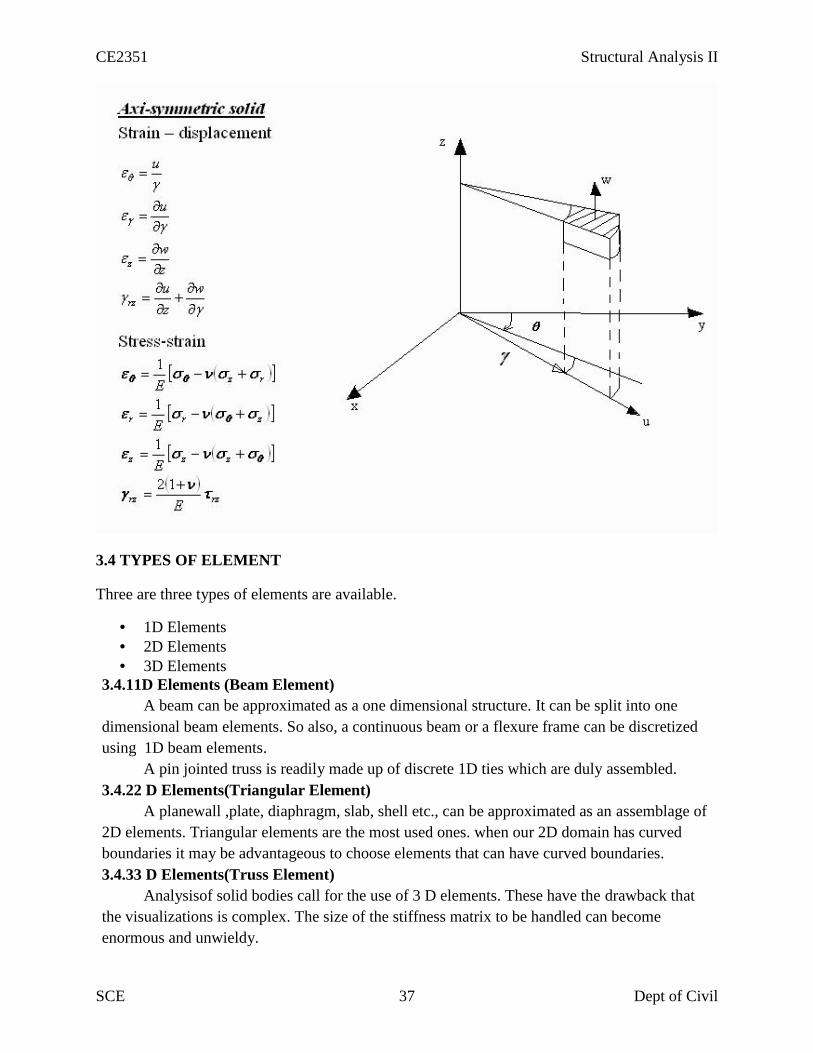
3.4 TYPES OF ELEMENT
Three are three types of elements are available.
1D Elements 2D Elements 3D Elements
3.4.11D Elements (Beam Element)A beam can be approximated as a one dimensional structure. It can be split into one
dimensional beam elements. So also, a continuous beam or a flexure frame can be discretizedusing 1D beam elements.
A pin jointed truss is readily made up of discrete 1D ties which are duly assembled.3.4.22 D Elements(Triangular Element)
A planewall ,plate, diaphragm, slab, shell etc., can be approximated as an assemblage of2D elements. Triangular elements are the most used ones. when our 2D domain has curvedboundaries it may be advantageous to choose elements that can have curved boundaries.3.4.33 D Elements(Truss Element)
Analysisof solid bodies call for the use of 3 D elements. These have the drawback thatthe visualizations is complex. The size of the stiffness matrix to be handled can becomeenormous and unwieldy.

CE2351 Structural Analysis II
SCE 38 Dept of Civil
3.5 PLANE STRESS AND PLANE STRAIN
The plane stress problem is one in which two dimensions ,length and breadth arecomparable and thickness dimension is very small (less than 1/10).Hence normal stress σ2 andshear stresses τxz,τyzare zero.
{σ }= [D]{e }[D]=Stress strain relationship matrix (or) constitutive matrix for plane stress problems.
We have seen that in the Z direction the dimension of the plate in the plane stressproblem is very small. In plane strain problem, on the contrary the structure is infinitely long inthe Z direction. Moreover the boundary and body forces do not vary in the Z directions.
{σ }= [D]{e }[D]=Stress strain relationship matrix (or) constitutive matrix for plane strain problems.

CE2351 Structural Analysis II
SCE 39 Dept of Civil
CHAPTER 4
PLASTIC ANALYSIS OF STRUCTURES
Statically indeterminate axial problems – Beams in pure bending – Plastic moment of resistancePlastic modulus – Shape factor – Load factor – Plastic hinge and mechanism – Plasticanalysis of indeterminate beams and frames – Upper and lower bound theorems
4.1.Statically indeterminate axial problems
Intheseanalysesweused superposition often,knowing thatforalinearlyelasticstructureitwasvalid.However,an elastic analysisdoesnotgiveinformation abouttheloadsthatwill actually collapseastructure.An indeterminatestructuremay sustainloadsgreaterthantheloadthatfirstcauses ayieldtooccur at anypointinthestructure.
Infact,astructurewillstandaslongasitisabletofindredundancies toyield.Itisonly whenastructurehasexhaustedallofitsredundancieswillextraloadcausesit tofail.Plasticanalysisisthemethodthroughwhichtheactualfailureloadof astructureiscalculated,andaswillbeseen,thisfailureloadcanbesignificantly greaterthan the elasticload capacity.
Tosummarizethis,Prof.SeandeCourcy(UCD)usedtosay:“astructureonlycollapseswhenithas exhaustedallmeans ofstanding”.Before analyzingcomplete structures, we review material and cross sectionbehaviorbeyondtheelasticlimit.
4.2. Beams in pure bending4.2.1. MaterialBehavior
Auniaxialtensilestressonaductile materialsuchasmild steeltypicallyprovidesthefollowinggraphofstress versus strain:
Ascanbeseen,thematerialcansustainstrainsfarinexcessofthestrainatwhichyield occursbeforefailure.This propertyofthematerialis calledits ductility.Thoughcomplex models do exist toaccurately reflect theabovereal behaviourofthematerial,themostcommon,andsimplest,modelistheidealizedstress-straincurve.Thisisthecurveforanidealelastic-plasticmaterial(whichdoesn’texist), andthegraphis:

CE2351 Structural Analysis II
SCE 40 Dept of Civil
As canbeseen, oncetheyieldhasbeenreacheditis takenthatanindefiniteamountofstraincanoccur. Sincesomuchpost-yieldstrainismodeled, theactualmaterial(orcross section)mustalsobecapableofallowingsuchstrains.Thatis,itmustbesufficientlyductilefortheidealized stress-straincurvetobevalid.Nextweconsiderthebehaviourof acrosssectionofanideal elastic-plasticmaterialsubjecttobending.In doingso,weseektherelationshipbetween appliedmomentandtherotation(ormoreaccurately, thecurvature)ofacross section.
4.2.2.Moment-RotationCharacteristics ofGeneralCross Section
Weconsider anarbitrarycross-sectionwithaverticalplaneofsymmetry,whichisalsotheplaneofloading.Weconsiderthecrosssectionsubjecttoanincreasingbendingmoment,andassess thestressesateach stage.
Cross sectionandStresses

CE2351 Structural Analysis II
SCE 41 Dept of Civil
Stage1– ElasticBehaviour
Moment-Rotation Curve
Theappliedmomentcauses stresses overthecross-sectionthatareallless thantheyieldstress ofthematerial.Stage2–YieldMoment
Theappliedmomentisjustsufficientthattheyieldstressof thematerialisreachedattheoutermostfibre(s)ofthecross-section.Allotherstressesinthecrosssectionarelessthantheyieldstress.Thisislimitofapplicabilityofanelasticanalysisandof elasticdesign.Sinceallfibresareelastic, theratioofthedepthoftheelastictoplasticregions,Stage3–Elasto-PlasticBending
Themomentapplied to thecrosssection hasbeenincreasedbeyond theyieldmoment.Sincebytheidealizedstress-strain curvethematerial cannotsustain astressgreaterthanyieldstress,thefibresattheyieldstresshaveprogressedinwardstowardsthecentreof thebeam.Thusoverthe crosssectionthereisanelasticcoreandaplasticregion.Theratioofthedepthoftheelasticcoretotheplasticregionis .Sinceextramomentis beingappliedandnostressisbiggerthantheyieldstress,extrarotationof thesectionoccurs:themoment-rotationcurvelossesitslinearityand curves,givingmorerotationperunitmoment(i.e.loosesstiffness).Stage4–PlasticBending
Theappliedmomenttothecrosssectionissuch thatallfibresin thecrosssection areatyieldstress.ThisistermedthePlasticMomentCapacityof thesection sincetherearenofibresatanelasticstress,Alsonotethatthefullplasticmomentrequiresaninfinitestrainattheneutralaxis

CE2351 Structural Analysis II
SCE 42 Dept of Civil
andsoisphysicallyimpossibletoachieve.However,itisclosely approximatedin practice.Anyattemptatincreasingthemomentat thispointsimply resultsinmorerotation,oncethecross-sectionhassufficientductility.Thereforeinsteelmembersthecrosssectionclassificationmustbeplasticandinconcretemembers thesectionmustbeunder-reinforced.
Stage5–StrainHardening
Duetostrainhardeningofthematerial,asmallamountofextramomentcanbesustained.
Theabovemoment-rotationcurverepresents thebehaviourofacrosssectionofaregular elastic-plasticmaterial.However,itis usuallyfurthersimplifiedasfollows:
With thisidealizedmoment-rotation curve,thecrosssectionlinearlysustainsmomentupto theplasticmomentcapacityofthesectionandthenyieldsinrotationanindeterminateamount.Again,tousethisidealization,theactual sectionmustbecapableofsustaininglargerotations–thatisitmustbeductile.Analysis ofRectangularCross Section
Sincewenowknowthatacrosssectioncansustainmoreloadthanjusttheyieldmoment,weareinterestedinhowmuchmore.Inotherwordswewanttofindtheyieldmomentandplasticmoment,andwedosoforarectangularsection.Takingthestressdiagramsfromthoseofthe moment-rotationcurveexaminedpreviously,wehave:

CE2351 Structural Analysis II
SCE 43 Dept of Civil
4.3.ShapeFactorThus theratioofelastictoplasticmomentcapacityis:
Thisratioistermedtheshapefactor,f,andisapropertyofacrosssectionalone.Forarectangularcross-section,wehave:
Andsoarectangularsectioncansustain50%moremomentthantheyieldmoment,beforeaplastichingeisformed.Thereforetheshapefactorisagoodmeasureoftheefficiencyofacross sectioninbending.Shapefactors forsomeothercross sections are

CE2351 Structural Analysis II
SCE 44 Dept of Civil
4.4.PlasticHinge
Notethatoncetheplasticmomentcapacityisreached,thesectioncanrotatefreely–thatis,itbehaveslikeahinge,exceptwithmomentofMpatthehinge.Thisis termedaplastichinge,andisthebasisforplasticanalysis.Attheplastichingestressesremainconstant,butstrainsand hencerotationscanincrease.
4.4.1.Methods ofPlasticAnalysis
1. TheIncrementalMethod
Thisisprobably themostobviousapproach:theloadson thestructureareincrementeduntilthefirstplastichingeforms.Thiscontinuesuntilsufficient hingeshaveformedtocollapsethestructure.Thisisalabour-intensive,‘brute-force’,approach,butonethatismostreadilysuitedforcomputerimplementation.
2. TheEquilibrium(orStatical) Method
In thismethod,freeandreactantbendingmomentdiagramsaredrawn.Thesediagramsareoverlaidtoidentifythelikelylocations of plastichinges.Thismethodthereforesatisfies theequilibriumcriterionfirstleavingthetwo remainingcriteriontoderivedtherefrom.
3.The Kinematic (or Mechanism) Method
In this method, a collapse mechanism is first postulated. Virtual work equations are then written forthis collapse state, allowing the calculations of the collapse bending moment diagram. This methodsatisfies the mechanism condition first, leaving the remaining two criteria to be derived there from.
We will concentrate mainly on the Kinematic Method, but introduce now the Incremental Methodto illustrate the main concepts.
4.4.1.1. IncrementalMethod
Example1– ProppedCantilever
We now assess the behaviorof a simple statically indeterminate structure under
increasingload.Weconsideraproppedcantilever withmid-spanpointload:

CE2351 Structural Analysis II
SCE 45 Dept of Civil

CE2351 Structural Analysis II
SCE 46 Dept of Civil
Sincethepeakmomentsarelessthan theyieldmoments,weknow
thatyieldstresshasnotbeen reachedatany pointin
thebeam.Also,themaximummomentoccursatAandsothispointwill firstreachtheyieldmoment.
4.4.1.2.EquilibriumMethod
Introduction
Toperformthis analysis wegenerallyfollowthefollowingsteps:
1.Findaprimary structurebyremoving redundantuntilthestructureis staticallydeterminate;
2.Drawtheprimary(orfree)bendingmomentdiagram;
3.DrawthereactantBMDforeachredundant,as appliedtotheprimary structure;
4.ConstructacompositeBMDbycombingtheprimaryand reactantBMDs;
CE2351 Structural Analysis II
SCE 47 Dept of Civil
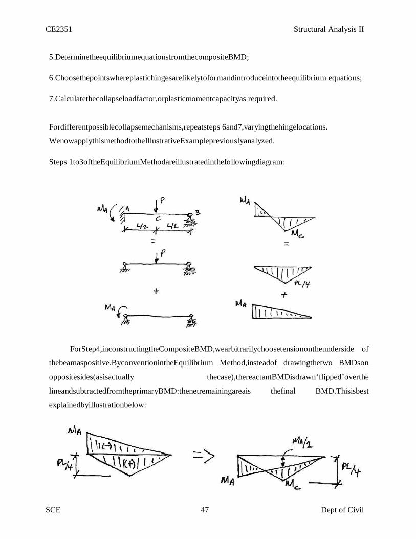
5.DeterminetheequilibriumequationsfromthecompositeBMD;
6.Choosethepointswhereplastichingesarelikelytoformandintroduceintotheequilibrium equations;
7.Calculatethecollapseloadfactor,orplasticmomentcapacityas required.
Fordifferentpossiblecollapsemechanisms,repeatsteps 6and7,varyingthehingelocations.
WenowapplythismethodtotheIllustrativeExamplepreviouslyanalyzed.
Steps 1to3oftheEquilibriumMethodareillustratedinthefollowingdiagram:
ForStep4,inconstructingtheCompositeBMD,wearbitrarilychoosetensionontheunderside of
thebeamaspositive.ByconventionintheEquilibrium Method,insteadof drawingthetwo BMDson
oppositesides(asisactually thecase),thereactantBMDisdrawn‘flipped’overthe
lineandsubtractedfromtheprimaryBMD:thenetremainingareais thefinal BMD.Thisisbest
explainedbyillustrationbelow:

CE2351 Structural Analysis II
SCE 48 Dept of Civil
ForStep7, wesolvethis equationforthecollapseload:

CE2351 Structural Analysis II
SCE 49 Dept of Civil
4.4.1.3 KinematicMethodUsingVirtualWork
Introduction
Probably theeasiestway tocarry outaplasticanalysisisthrough theKinematicMethodusing
virtual work.Todothisweallowthepresumedshapeatcollapsetobethecompatible
displacementset,andtheexternalloadingandinternalbendingmomentstobetheequilibrium set.Wecan
thenequate externalandinternalvirtualwork,andsolveforthecollapseloadfactor
forthatsupposedmechanism.
Remember:
Equilibrium set:theinternalbendingmoments atcollapse;
Compatibleset:thevirtualcollapsedconfiguration (seebelow).
Notethatin theactual collapseconfiguration thememberswillhaveelasticdeformationin
betweentheplastichinges.However,sinceavirtual displacementdoesnothavetobereal,only
compatible,wewillchoosetoignoretheelasticdeformationsbetweenplastichinges,andtake
themembers tobestraightbetweenthem.

CE2351 Structural Analysis II
SCE 50 Dept of Civil
4.5.CollapseMechanism
Soforourpreviousbeam,we know thatwe require twohingesforcollapse(onemore thanits
degreeofredundancy),andwethinkthatthehinges willoccurunderthepoints ofpeakmoment,
AandC.Thereforeimposeaunitvirtual displacementatCandrelatethecorrespondingvirtual rotations
ofthehinges using,

CE2351 Structural Analysis II
SCE 51 Dept of Civil
4.5.1 OtherCollapseMechanisms
Forthecollapsemechanismlookedatpreviously,itseemed obviousthat theplastichingein the
spanshouldbebeneaththeload.Butwhy?Usingvirtual workwecan examineanypossible
collapsemechanism.Solet’sconsiderthefollowingcollapsemechanismandseewhytheplastic hingehas
tobelocatedbeneaththeload.
PlasticHinge betweenAandC:ImposingaunitvirtualdeflectionatB,wegetthefollowingcollapsemechanism:

CE2351 Structural Analysis II
SCE 52 Dept of Civil
Andsoweseethatthecollapseloadfactorforthismechanismdependsonthepositionofthe
plastichingeinthespan.
4.6.PlasticAnalysisofBeams
Example2–Fixed-FixedBeamwithPointLoad
Tostarttheproblem, weexaminetheusual elasticBMDtoseewheretheplastic hingesare
likelytoform:
Wealsoneedtoknowhowmanyhinges arerequired.Thisstructureis 3˚staticallyindeterminate
andsowemightexpectthenumberofplastichingesrequiredtobe4.However,sinceoneofthe
indeterminaciesishorizontalrestraint,removingitwouldnotchangethebendingbehaviourof thebeam.
Thusforabendingcollapseonly2indeterminaciesapplyandsoitwill only take3 plastichinges
tocausecollapse.SolookingattheelasticBMD,we’llassumeacollapsemechanismwiththe3plastichinges
at thepeakmomentlocations:A,B,andC.

CE2351 Structural Analysis II
SCE 53 Dept of Civil
WeneedtocheckthatthisisthecorrectsolutionusingtheUniquenessTheorem:

CE2351 Structural Analysis II
SCE 54 Dept of Civil
AndsotheappliedloadisinequilibriumwiththefreeBMDofthecollapseBMD.
2.Mechanism:
Fromtheproposedcollapsemechanismitis apparentthatthebeamis amechanism.
3.Yield:
FromthecollapseBMDitcanbeseenthatnowhereis exceeded.PM
Thusthesolutionmeetsthethreeconditionsandso,bytheUniquenessTheorem,isthecorrect solution.
Example3–ProppedCantileverwithTwoPointLoads
Forthefollowingbeam,foraloadfactorof2.0,findtherequiredplasticmoment capacity:

CE2351 Structural Analysis II
SCE 55 Dept of Civil
Allowingfortheloadfactor,weneedtodesignthe beamfor thefollowingloads:
Once againwe try to picture possible failure mechanisms. Since
maximummomentsoccurunderneathpointloads,thereare tworeal possibilities:

CE2351 Structural Analysis II
SCE 56 Dept of Civil
Mechanism-1
Mechanism-2
Therefore,we analyseboth and apply the UpperboundTheoremto find the
designplasticmomentcapacity.
Mechanism1:PlasticHingeatC:
CE2351 Structural Analysis II
SCE 57 Dept of Civil
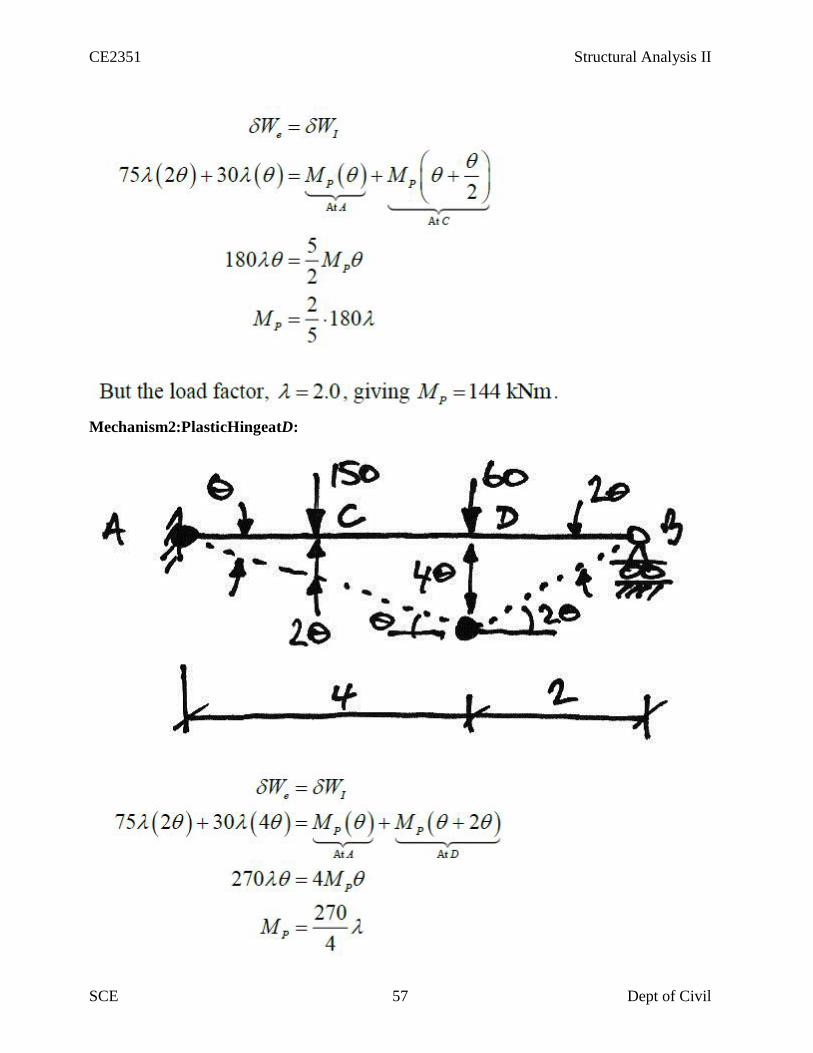
Mechanism2:PlasticHingeatD:

CE2351 Structural Analysis II
SCE 58 Dept of Civil
1.Equilibrium:UsingtheBMDatcollapse,we’llcheckthattheheightofthefreeBMDisthatof
theequivalentsimply-supportedbeam.FirstlythecollapseBMDfromMechanism1is:
Hence,thetotalheightsofthefreeBMDare:
Checkingtheseusingasimply-supportedbeamanalysis

CE2351 Structural Analysis II
SCE 59 Dept of Civil
Thus,usingappropriatefreebodydiagrams ofACandDB:
AndsotheappliedloadisinequilibriumwiththefreeBMDofthecollapseBMD.2.Mechanism:
Fromtheproposedcollapsemechanismitisapparentthatthebeamisamechanism.Also,sinceitisaproppedcantileverand thusonedegreeindeterminate,werequiretwoplastichingesforcollapse,andthesewehave3.Yield:
FromthecollapseBMDitcanbeseenthatnowhereis thedesignexceeded.144kNmThusbytheUniquenessTheoremwehavethecorrectsolution.Lastly,we’llexaminewhytheMechanism2collapseisnotthecorrectsolution.Sincethevirtual workmethodprovidesan upperbound,then,bytheUniquenessTheorem,itmustnotbethe correctsolutionbecauseitmustviolatetheyieldcondition.Using thecollapseMechanism2todeterminereactions,wecan draw thefollowingBMDforcollapseMechanism2:
FromthisitisapparentthatMechanism2isnottheuniquesolution,andsothedesignplastic moment
capacity must be144kNmasimpliedpreviously fromtheUpperboundTheorem.
4.BasicCollapseMechanisms:In frames,the basicmechanismsofcollapseare:

CE2351 Structural Analysis II
SCE 60 Dept of Civil
Beam-typecollapse
SwayCollapse
CombinationCollapse
5.CombinationofMechanismsOneofthemostpowerfultoolsinplasticanalysisis CombinationofMechanisms.Thisallows us
toworkoutthevirtualworkequationsforthebeamandswaycollapsesseparatelyandthen
combinethemtofindthecollapseloadfactorforacombinationcollapsemechanism.
Combinationof mechanismsis based onthe ideathat thereareonlya certain number of
independentequilibriumequationsforastructure.Anyfurtherequationsareobtainedfroma

CE2351 Structural Analysis II
SCE 61 Dept of Civil
combinationoftheseindependentequations.
Sinceequilibriumequationscanbeobtainedusing
virtualworkappliedtoapossiblecollapsemechanism,itfollowsthatthereareindependent
collapsemechanisms,andothercollapsemechanismsthatmaybeobtainedformacombination
oftheindependentcollapsemechanisms.
6.SimplePortalFrame
Inthisexamplewewillconsiderabasicprismatic(soallmembershavethesame
plasticmomentcapacity)rectangularportalframewithpinnedfeet:

CE2351 Structural Analysis II
SCE 62 Dept of Civil
Wewillconsiderthisgeneralcasesothatwecaninferthepropertiesandbehaviourofallsuch
frames.Wewillconsidereachofthepossiblemechanisms outlinedabove.
7.Beam collapse:
Thepossiblebeamcollapselooks as follows:
CE2351 Structural Analysis II
SCE 63 Dept of Civil
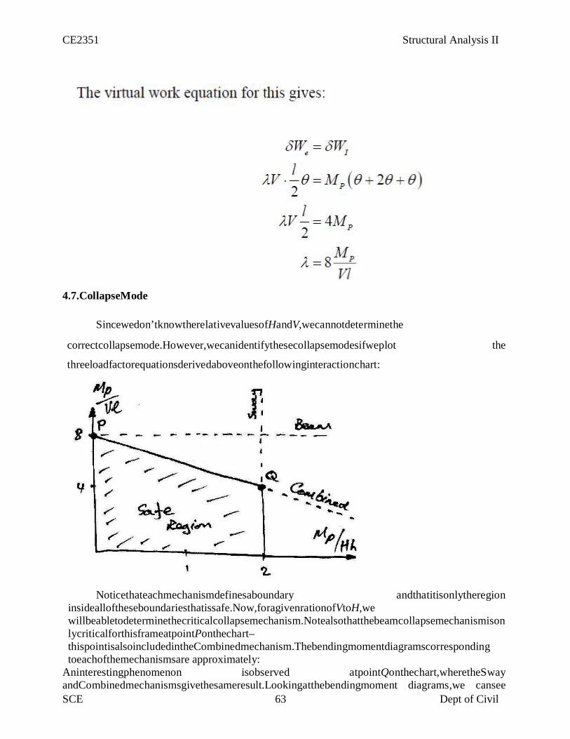
4.7.CollapseMode
Sincewedon’tknowtherelativevaluesofHandV,wecannotdeterminethe
correctcollapsemode.However,wecanidentifythesecollapsemodesifweplot the
threeloadfactorequationsderivedaboveonthefollowinginteractionchart:
Noticethateachmechanismdefinesaboundary andthatitisonlytheregioninsidealloftheseboundariesthatissafe.Now,foragivenrationofVtoH,wewillbeabletodeterminethecriticalcollapsemechanism.NotealsothatthebeamcollapsemechanismisonlycriticalforthisframeatpointPonthechart–thispointisalsoincludedintheCombinedmechanism.Thebendingmomentdiagramscorrespondingtoeachofthemechanismsare approximately:
Aninterestingphenomenon isobserved atpointQonthechart,wheretheSwayandCombinedmechanismsgivethesameresult.Lookingatthebendingmoment diagrams,we cansee

CE2351 Structural Analysis II
SCE 64 Dept of Civil
thatthis occursasthe momentatthe topofthe leftcolumn becomesequaltothe mid-spanmomentof thebeam:

CE2351 Structural Analysis II
SCE 65 Dept of Civil
4.8. Upper bound(Unsafe)Theorem:
This canbestatedas:
If abendingmomentdiagramisfoundwhichsatisfiesthe conditionsof equilibrium
andmechanism(butnotnecessarilyyield),thenthecorresponding loadfactoris eithergreaterthanor
equalto the trueloadfactorat collapse.
Thisis calledtheunsafetheorembecauseforanarbitrarilyassumedmechanismtheloadfactoris
eitherexactly right(when theyieldcriterionismet)oriswrongandistoolarge,leadinga designer
tothinkthattheframecancarrymoreloadthanis actuallypossible.
4.9. Lowerbound(Safe)Theorem:
Ifabendingmomentdiagramisfoundwhichsatisfiestheconditionsofequilibriumandyield
(butnotnecessarilythatofmechanism),then thecorrespondingload factoriseitherlessthanor
equaltothetrueloadfactor atcollapse.

CE2351 Structural Analysis II
SCE 66 Dept of Civil

CE2351 Structural Analysis II
SCE 67 Dept of Civil
CHAPTER 5SPACE AND CABLE STRUCTURES
Analysis of Space trusses using method of tension coefficients – Beams curved in planSuspension cables – suspension bridges with two and three hinged stiffening girders
5.1ANALYSIS OF SPACE TRUSSES USING METHOD OF TENSION COEFFICIENTS
5.1.1.Tension Co-efficient MethodThe tension co efficient for a member of a frame is defined as the pull or tension in that
member is divided by its length.t = T/l
Where t = tension co efficient for the memberT= Pull in the memberl = Length
5.1.2.Analysis Procedure Using Tension Co-efficient – 2D Frames
1.List the coordinates of each joint (node)of the truss.2.Determine the projected lengths Xij and Yij of each member of the truss. Determine the supportlengths lij of each member using the equation lij =√Xij
2+Yij2
3. Resolve the the applied the forces at the joint in the X and Y directions. Determine the supportreactions and their X and Y components.4.Identify a node with only two unknown member forces and apply the equations of equilibrium.The solution yields the tension co efficient for the members at the node.5.Select the next joint with only two unknown member forces and apply the equations ofequilibrium and apply the tension co efficient.6.Repeat step 5 till the tension co efficient of all the members are obtained.7.Compute the member forces from the tension co efficient obtained as above using
Tij= tijx lij
5.1.3.Analysis Procedure Using Tension Co-efficient – Space Frames
1.In step 2 above the projected lengths Zij in the directions are also computed.Determine thesupport lengths lij of each member using the equation lij =√Xij
2+Yij2 +Zij
2
2.In step 3 above the components of forces and reactions in the Z directions are also to bedetermined.3.In step 4 and 5,each time, nodes with not more than three unknown member forces are to beconsidered.
Tetrahedron: simplestelementofstablespacetruss (sixmembers,fourjoints)expandbyadding3members and1jointeachtimeDeterminacyandStabilityb+r<3junstableb+r=3jstaticallydeterminate(checkstability)b+r>3jstaticallyindeterminate(checkstability)

CE2351 Structural Analysis II
SCE 68 Dept of Civil
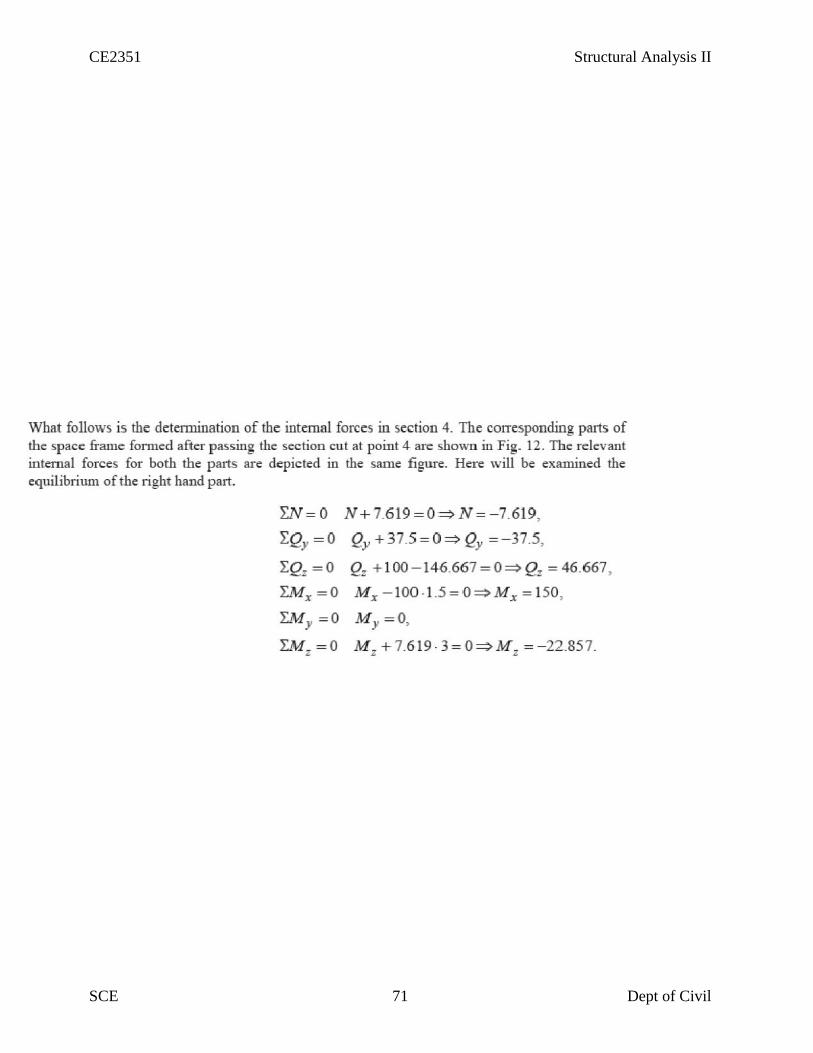
InternalForcesIn orderto obtain theinternalforcesataspecifiedpoint,weshouldmakesection cut
perpendiculartotheaxis ofthememberatthis point.This sectioncutdivides thestructureintwoparts.Theportionofthestructureremovedfromthepartintoconsiderationshouldbereplacedbytheinternalforces.Theinternalforcesensuretheequilibriumoftheisolatedpartsubjectedtotheactionofexternalloadsandsupportreactions.Afreebody diagramofeithersegmentofthecutmemberisisolatedandtheinternalloads couldbederivedbythesixequations ofequilibriumappliedtothesegmentintoconsideration.
5.1.Example
InthefollowingexampleweshallconstructtheinternalforcesdiagramsforthegiveninFig.spaceframestructure. Theintroducedglobalcoordinatesystemisshowninthesamefigure.

CE2351 Structural Analysis II
SCE 69 Dept of Civil
The introduced local coordinate systems of the different elements of the space frame are
presentedinFig.Thetypical sectionswheretheinternalforcesmustbecalculated,inorderto
constructtherelevant diagrams,arenumbered from1to8inthesamefigure.Thetypical
sectionsareplacedatleastatthebeginningandattheendofeachelement(segment)ofthe
frame.Theinternalforces diagrams,inthelimitsof eachelement,couldbederivedbyusingthe
corresponding referenceandbasediagrams.

CE2351 Structural Analysis II
SCE 70 Dept of Civil
CE2351 Structural Analysis II
SCE 71 Dept of Civil

CE2351 Structural Analysis II
SCE 72 Dept of Civil

CE2351 Structural Analysis II
SCE 73 Dept of Civil

CE2351 Structural Analysis II
SCE 74 Dept of Civil
5.2.Example

CE2351 Structural Analysis II
SCE 75 Dept of Civil

CE2351 Structural Analysis II
SCE 76 Dept of Civil

CE2351 Structural Analysis II
SCE 77 Dept of Civil

CE2351 Structural Analysis II
SCE 78 Dept of Civil
5.2 BEAMS CURVED IN PLAN
5.2.1IntroductionArches are in fact beams with an initial curvature. The curvature is visible only in
elevation.In plan they they would appear in straight.the other cases of curved beams are ring beamssupporting water tanks,Silos etc.,beams supporting corner lintels and curved balconies etc.,Rampsin traffic interchanges invariably have curved in plan beams.
Curved beams in addition to the bending moments and shears would also develop torsionalmoments.
5.2.2.Moment,Shear and Torsion
The three diverse force components have one thing in common – the strain energy storedin a beam due to each type of force. Among the 3 we normally ignore the strain energy due toshear forces as negligible.
U = ∫M2ds/2EI+∫T2ds/2GJ

CE2351 Structural Analysis II
SCE 79 Dept of Civil
5.3. SUSPENSION CABLE5.3.1. Indroduction
Cablesandarchesareclosely related toeach otherandhencethey aregroupedin thiscourseinthesamemodule.Forlongspanstructures(fore.g.incasebridges)engineerscommonlyusecableorarchconstructionduetotheirefficiency.Inthefirst lessonofthismodule,cablessubjectedtouniformandconcentratedloadsarediscussed.Inthesecond lesson,arches ingeneralandthreehingedarchesinparticularalongwithillustrativeexamplesareexplained.
In thelasttwolessons ofthismodule, twohingedarchandhingeless archesareconsidered.Structure may be classified into rigid and deformable structures depending onchange in geometry ofthestructurewhilesupportingtheload.Rigidstructuressupportexternallyappliedloadswithout appreciable change intheir shape(geometry). Beamstrussesand framesare examplesofrigidstructures.
Unlikerigidstructures,deformablestructuresundergochangesintheirshapeaccordingtoexternallyappliedloads.However,itshouldbenotedthatdeformationsarestillsmall.Cablesandfabricstructuresaredeformablestructures.Cablesaremainly used to supportsuspensionroofs,bridgesand cablecarsystem. They arealsousedin electricaltransmissionlinesandforstructuressupportingradioantennas.In thefollowingsections,cablessubjectedtoconcentratedloadandcables subjectedtouniformloads areconsidered.
Theshapeassumedby aropeorachain(withnostiffness)undertheactionofexternalloadswhenhungfromtwosupportsisknownasafunicularshape. Cableisafunicular structure.Itiseasytovisualizethatacablehungfromtwosupportssubjectedtoexternal loadmustbeintenscable.Acablemaybedefinedasthestructureinpuretensionhavingthefunicularshapeof theload.(videFig.5.1and5.2).
As stated earlier, the cables are considered to be perfectly flexible (no flexuralstiffness)and inextensible.Astheyareflexibletheydonotresistshearforceandbendingmoment.Itissubjected toaxial tension only anditisalwaysacting tangentialtothecable at anypoint along thelength.If theweightof thecableisnegligibleascomparedwith theexternally appliedloadsthenitsself weightisneglectedintheanalysis.In thepresent analysisself weightisnotconsidered.
Consideracableasloadedin Fig.5.3.Letusassume thatthecablelengthsandsagat()areknown.Thefour reactioncomponentsatACDEBandB, cable tensionsineach ofthefour segmentsand threesagvalues:a totalof eleven unknown quantitiesaretobedetermined.Fromthegeometry,onecouldwritetwoforceequilibriumequations(0,0==ΣΣyxFF)ateachofthepointandDCBA,,,Ei.e.atotal of tenequationsandtherequiredonemoreequationmay bewrittenfromthegeometryof thecable.Forexample,ifoneof thesagisgiven then theproblemcan besolvedeasily.Otherwiseif the total lengthofthecableisgiventhentherequired equationmaybewritten as

CE2351 Structural Analysis II
SCE 80 Dept of Civil
Fig 5.1 Deformable Structure
Fig 5.2Unloaded Cable
Fig 5.3Cable in Tension
Cablesubjectedtouniformload.
Cablesareusedtosupportthedeadweightandliveloads ofthebridgedeckshavinglongspans.
Thebridgedecksaresuspendedfromthecableusingthehangers.Thestiffeneddeckprevents
thesupportingcablefrom changingitsshapebydistributingtheliveloadmovingoverit,fora
longerlengthofcable.In suchcases cableis assumedtobeuniformlyloaded.

CE2351 Structural Analysis II
SCE 81 Dept of Civil
Fig 5.4.Cable subjected to concentrated load
Fig 5.5.Cable Subjected to Uniformly Fig 5.6.Free Body Diagram
Distributed load

CE2351 Structural Analysis II
SCE 82 Dept of Civil
Considera cable which isuniformlyloaded asshown inFig 5.4.

CE2351 Structural Analysis II
SCE 83 Dept of Civil
Duetouniformlydistributedload,thecabletakesaparabolicshape.Howeverduetoits owndeadweightittakesashapeof acatenary. Howeverdeadweight of thecableis neglected in the presentanalysis.
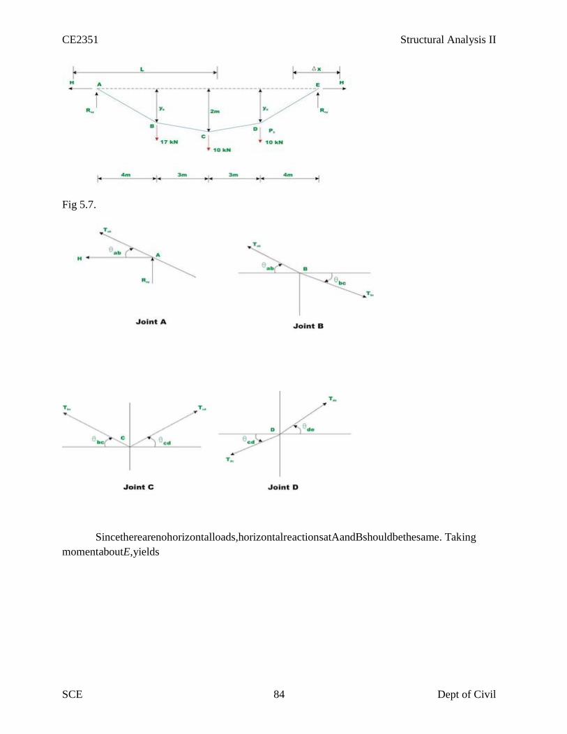
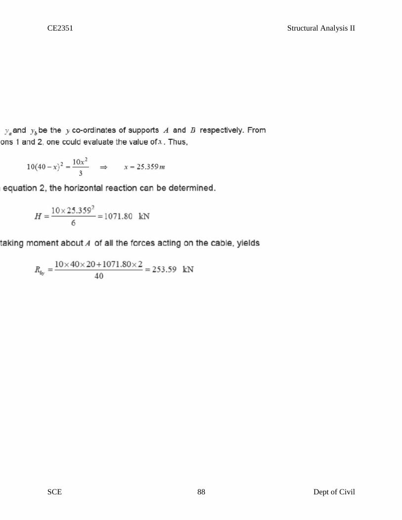
5.3.ExampleDeterminereactioncomponentsatA andB,tensioninthecable andthesag ofthecable showninFig.5.7.Neglectthe selfweightofthe cable in the analysis.
CE2351 Structural Analysis II
SCE 84 Dept of Civil
Fig 5.7.
Sincetherearenohorizontalloads,horizontalreactionsatAandBshouldbethesame. TakingmomentaboutE,yields

CE2351 Structural Analysis II
SCE 85 Dept of Civil

CE2351 Structural Analysis II
SCE 86 Dept of Civil

CE2351 Structural Analysis II
SCE 87 Dept of Civil
Fig 5.8
Fig 5.9
CE2351 Structural Analysis II
SCE 88 Dept of Civil
CE2351 Structural Analysis II
SCE 88 Dept of Civil
CE2351 Structural Analysis II
SCE 88 Dept of Civil

CE2351 Structural Analysis II
SCE 89 Dept of Civil
CE2351 Structural Analysis II
SCE 90 Dept of Civil
CE2351 Structural Analysis II
SCE 91 Dept of Civil

CE2351 Structural Analysis II
SCE 95 Dept of Civil
UNIT-I FLEXIBILITYMATRIXMETHOD FORINDETERMINATE STRUCTURES
1. Whatis meantby indeterminatestructures?Structures that do not satisfythe conditions of equilibrium are called indeterminatestructure. Thesestructures cannot besolved byordinaryanalysis techniques.
2. Whataretheconditions ofequilibrium?Thethreeconditionsofequilibriumarethesumofhorizontalforces,verticalforcesandmomentsat anyjoint should beequal to zero.
i.e.∑H=0;∑V=0;∑M=0
3. Differentiatebetween determinateand indeterminatestructures.Determinatestructurescanbesolvingusingconditionsofequilibriumalone(∑H=0;∑V=0;∑M=0). No otherconditions arerequired.Indeterminatestructurescannotbesolvedusingconditionsofequilibriumbecause(∑H≠0;∑V≠0;∑M≠0).Additionalconditionsarerequiredforsolvingsuchstructures.Usuallymatrixmethods areadopted.
4. Definedegreeofindeterminacy (i).Theexcessnumberofreactionsthatmakeastructureindeterminateiscalleddegreeofindeterminacy,andisdenotedby(i).Indeterminacyisalsocalleddegreeofredundancy.Indeterminacyconsists ofinternal andexternal indeterminacies.
i =II+EIwhereII=internal indeterminacyand EI=external indeterminacy.
5. Defineinternal and external indeterminacies.Internalindeterminacy(II)istheexcessnoofinternalforcespresentinamemberthatmakeastructureindeterminate.Externalindeterminacy(EI)isexcessnoofexternalreactionsinthememberthatmakethestructureindeterminate.
i =II+EI;EI=r– e;wherer=no ofsupport reactions and e=equilibrium conditions
II=i –EIe=3 (planeframes) ande=6 (spaceframes)
6. Write theformulaefordegreeofindeterminacy for:(a)Two dimensional pinjointed truss(2D Truss)
i =(m+r)– 2j wherem=no ofmembersr=no ofreactions j=no ofjoints
(b)Two dimensional rigid frames/plane rigid frames (2DFrames)i =(3m+r)– 3j wherem=no ofmembers
r=no ofreactions j =no ofjoints

CE2351 Structural Analysis II
SCE 96 Dept of Civil
(c)Threedimensional spacetruss (3D Truss)i =(m+r)– 3j wherem=no ofmembers
r=no ofreactions j=no ofjoints
(d)Threedimensional spaceframes (3DFrame)i =(6m+r)– 6j wherem=no ofmembers
r=no ofreactions j=no ofjoints
7. Determine thedegreeofindeterminacy for the following2D truss.i =(m+r)-2jwherem=19
r=4j =10e=3
∑i =(19+4)–2x10=3External indeterminacyEI=r–e=4–3=1∑Internal indeterminacy II=i–EI=3-1=2
8. Determine the total, internal and external degreeofindeterminacy for theplanerigid framebelow.
i =(3m + r)– 3jwherem=7
r=4 j=6e=3
∑i =(3x7+ 4)– (3x6) =7External indeterminacyEI=r–e=4–3=1∑Internal indeterminacy II=i–EI=7-1=6
9. Determinei, EI, II for thegiven plane truss.i =(m + r)– 2jwherem=3
r=4 j=3e=3
∑i =(3+ 4)–(2x3) =1External indeterminacyEI=r–e=4–3=1∑Internal indeterminacyII=i–EI=1-1=0

CE2351 Structural Analysis II
SCE 97 Dept of Civil
10. Find theindeterminacyfor thebeams given below.Forbeams degreeofindeterminacyisgiven byi =r–e
(a)
i =r–e wherer=no of reactions, e=no of equilibrium conditions r=4ande=3∑i =4–3=1
(b)
i =r–ewherer=5 ande=3
∑i =5–3=2
11. Find theindeterminacyfor thegiven rigid planeframe.i =(3m + r)– 3jwherem=3
r=4j =4
∑i =(3x3+ 4)– (3x4) =1External indeterminacyEI=r–e=4–3=1∑Internal indeterminacy II=i–EI=1-1=0
12. Find theindeterminacyofthespace rigid frame.i =(6m + r)– 6jwherem=8
r=24 (i. e. 6persupportx4)j =8 e=6
∑i =(6x8+24)– (6x 8) =24External indeterminacyEI=r–e=24–6=18
∑Internal indeterminacy II=i–EI=24-18=6

CE2351 Structural Analysis II
SCE 98 Dept of Civil
13. Find theindeterminacyfor thegiven space truss.i =m +r-3jwherem=3
r=18 (i. e. 6reactions persupport x3)j =4
∑i =(3+18)– (3x4) =9External indeterminacyEI=r–e=18–6=12∑Internal indeterminacy II=i–EI=9-12=-3
14. Whatare thedifferent methods ofanalysis of indeterminatestructures.Thevarious methods adopted forthe analysis ofindeterminatestructures include:(a)Flexibilitymatrixmethod.(b) Stiffness matrixmethod(c)Finite Element method
15. Briefly mention the two types ofmatrixmethods ofanalysis ofindeterminatestructures.
Thetwo matrixmethodsof analysis ofindeterminatestructuresare:(a)Flexibilitymatrixmethod– This method is also called the forcemethod inwhich the
forces in thestructurearetreated as unknowns. Theno of equations involved is equal tothedegreeofstaticindeterminacyofthestructure.
(b)Stiffness matrixmethod– This is also called thedisplacement method in which thedisplacements thatoccurin thestructurearetreated as unknowns. Theno ofdisplacements involved is equal to theno ofdegrees of freedom ofthestructure.
16. Definea primary structure.Astructure formed bythe removingthe excess orredundant restraints fromanindeterminatestructuremakingit staticallydeterminateis called primarystructure. This isrequired forsolvingindeterminatestructures byflexibilitymatrixmethod.
17. Give theprimary structures for thefollowing indeterminatestructures.Indeterminatestructure PrimaryStructure
18. Definekinematicindeterminacy(Dk)orDegreeofFreedom (DOF)Degrees offreedom is defined as theleast no ofindependent displacementsrequired todefinethedeformed shapeofastructure. Therearetwo types of DOF: (a)Nodal typeDOFand(b)Joint typeDOF.

CE2351 Structural Analysis II
SCE 99 Dept of Civil
19. Briefly explain the twotypes ofDOF.(a)Nodal type DOF– This includes the DOFat thepoint of application of concentrated
load ormoment, at asection wheremoment ofinertia changes, hingesupport, rollersupport and junction oftwo ormoremembers.
(b)Joint type DOF– This includes the DOFat thepoint wheremoment ofinertiachanges, hingeand rollersupport, and junction oftwo ormoremembers.
20. Forthevarious support conditions shown belowgive the DOFs.
(a) No DOF
(b) 1– DOF(c) 2– DOF(d) 1– DOF
21. Forthe truss shown below,whatis the DOF?Pin jointed planeframe/truss
DOF/ Dk = 2j–rwherer=no of reactions
j = no ofjoints
22. Define compatibility in forcemethod ofanalysis.Compatibilityis definedas the continuitycondition on thedisplacements ofthestructureafterexternal loads are applied to thestructure.
23. Define theForceTransformation Matrix.The connectivitymatrixwhich relates theinternalforcesQ and theexternal forces R isknown as the forcetransformation matrix. Writingit in amatrixform,
{Q} =[b]{R}whereQ=member forcematrix/vector
b= forcetransformationmatrixR = external force/loadmatrix/ vector
24. Whatare therequirements to besatisfied whileanalyzing a structure?Thethreeconditions to besatisfied are:(a)Equilibrium condition(b)Compatibilitycondition(c)Forcedisplacement condition

CE2351 Structural Analysis II
SCE 100 Dept of Civil
25. Defineflexibility influence coefficient(fij)Flexibilityinfluence coefficient(fij)is defined as thedisplacement at joint ‘i’dueto aunitload at joint ‘j’, while all otherjoints arenot load.
26. Write theelementflexibility matrix(f)fora truss member.The element flexibilitymatrix(f) foratruss memberis given by
=

CE2351 Structural Analysis II
SCE 101 Dept of Civil
UNIT –II STIFFNESS MATRIXMETHOD
1. Whatarethebasicunknowns in stiffness matrix method?In thestiffness matrixmethod nodal displacementsaretreatedas thebasicunknowns forthesolution ofindeterminatestructures.
2. Definestiffness coefficientkij.Stiffness coefficient ‘kij’is defined as the forcedeveloped at joint ‘i’duetounitdisplacementat joint ‘j’while all otherjoints arefixed.
3. Whatis thebasicaimofthestiffness method?The aim ofthestiffnessmethod is to evaluatethevalues ofgeneralized coordinates ‘r’knowingthestructurestiffness matrix‘k’ and nodal loads ‘R’through thestructureequilibrium equation.
{R} =[K]{r}
4. Whatis thedisplacement transformationmatrix?The connectivitymatrixwhich relates theinternaldisplacement ‘q’and theexternaldisplacement‘r’is known as thedisplacement transformation matrix ‘a’.
{q} =[a]{r}
5. Howarethebasicequations ofstiffness matrixobtained?Thebasicequations ofstiffness matrixareobtained as:
EquilibriumforcesCompatibilityofdisplacementsForcedisplacement relationships
6. Whatis theequilibriumcondition usedin thestiffness method?Theexternal loads and theinternal memberforcesmust bein equilibrium atthenodalpoints.
7. Whatis meantby generalized coordinates?Forspecifyingaconfiguration ofasystem, acertain minimum no ofindependentcoordinatesarenecessary. Theleast no ofindependent coordinates thatareneeded tospecifytheconfigurationis known as generalized coordinates.
8. Whatis thecompatibility condition used in theflexibility method?Thedeformed elements fit togetherat nodal points.
9. Writeabout theforcedisplacement relationship.Therelationship ofeachelement must satisfythestress-strain relationship oftheelementmaterial.
10. Writetheelementstiffness fora truss element.Theelement stiffness matrixforatruss element isgiven by

CE2351 Structural Analysis II
SCE 102 Dept of Civil
11. Writetheelementstiffnessmatrix fora beamelement.Theelement stiffness matrixforabeam element is given by
12. Compareflexibility method and stiffness method.Flexibilitymatrixmethod
Theredundant forces aretreated as basicunknowns.Thenumberofequationsinvolved is equal to thedegreeofstaticindeterminacy
ofthestructure.Themethod is thegeneralization of consistent deformation method.Different proceduresareused fordeterminateandindeterminatestructures
Stiffness matrixmethodThejoint displacements aretreatedas basicunknownsThenumberofdisplacements involved is equal to theno ofdegrees offreedom of
thestructureThemethod is thegeneralization oftheslopedeflection method.Thesameprocedureis used forboth determinateand indeterminatestructures.
13. Is itpossibleto developtheflexibility matrix foran unstablestructure?Inorderto develop theflexibilitymatrixforastructure, it has to bestableanddeterminate.
14. Whatis therelation between flexibility and stiffness matrix?The element stiffness matrix‘k’is theinverseofthe element flexibilitymatrix‘f’ and isgivenbyf=1/k ork =1/f.
15. Whatarethetypeofstructures that can besolved using stiffness matrix method?Structures such as simplysupported, fixed beams and portal frames can besolved usingstiffness matrixmethod.
16. Givetheformula forthesizeoftheGlobal stiffness matrix.Thesizeoftheglobal stiffness matrix(GSM) =No: ofnodes xDegrees offreedom pernode.
17. List theproperties ofthestiffness matrixTheproperties ofthestiffness matrixare:
It isasymmetricmatrix Thesum of elements in anycolumn must be equal to zero. It is an unstableelementthereforethedeterminantis equal to zero.
18. Whyis thestiffness matrixmethodalso called equilibrium method ordisplacementmethod?

CE2351 Structural Analysis II
SCE 103 Dept of Civil
Stiffness method is based on thesuperposition ofdisplacements and henceis also known asthedispalcement method. And sinceit leads to the equilibrium equations themethod is alsoknown as equilibrium method.
19. Ifthe flexibilitymatrixis givenas
Writethe correspondingstiffness matrix.
Stiffness matrix= 1/(Flexibilitymatrix)i.e. [K]=[F]-1
20. Writethen stiffness matrixfora 2Dbeam element.Thestiffness matrixfora2Dbeam element is given by

CE2351 Structural Analysis II
SCE 104 Dept of Civil
UNIT III FINITE ELEMENT METHOD
1. Whatis meantbyFinite elementmethod?Finite element method (FEM)is anumerical technique forsolvingboundaryvalue problemsin which alargedomain is divided into smallerpieces or elements. Thesolution isdetermined byasuumingcertianploynomials.Thesmall pieces arecalled finiteelementand thepolynomials arecalled shapefunctions.
2. Listout theadvantages ofFEM. Sincetheproperties of each element are evaluatedseparatelydiffernt material
properties can beincorporated foreach element. Thereis no restriction in theshapeofthemedium. Anytypeofboundarycondition can be adopted.
3. Listout thedisadvantages ofFEM.The computational cost is high.
Thesolution is approximate and severalchecksare required.
4. Mention thevarious coordinates in FEM. Local or element coordinates
Natural coodinates Simplenatural coodinates
Areacoordiantesor Triangularcoordiantes Generalisedcoordinates
5. Whatare thebasicsteps in FEM? Discretization ofthestructure Selection ofsuitabledisplacement fuction
Findingtheelement properties Assemblingthe elementproperties
Applyingtheboundaryconditions Solvingthesystem of equations Computingadditional results
6. Whatis meantby discretization?Discretization is theprocess ofsubdividingthegiven bodyinto anumberof elementswhich results in asystem of equivalent finite elements.
7. Whatare thefactors governing theselection of finite elements?
CE2351 Structural Analysis II
SCE 105 Dept of Civil
ThegeometryofthebodyThenumberofindependent spacecoordinates
Thenatureofstress variation expected
8. Definedispalcementfunction.Displcementfunction is defined as simple functions which areassumed toapproximatethedisplacements foreach element. Theymayassumed in the form ofpoynomials, ortrignometricalfunctions.
9. Briefly explain afewterminology used in FEM.Thevarious terms used in FEM are explained below.
Finite element–Small elements used forsubdividingthegiven domain tobeanalysedarecalled finiteelements. Theseelements maybe1D, 2Dor 3Delements dependin on thetypeofstructure.
Nodes and nodal points– Theintersection ofthediffernt sides ofelementsarecalled nodes. Nodes areoftwo types – external nodes and internal nodes.
oExternal nodes – Thenodal point connectingadjacent elements.oInternal nodes– The extranodes used to increasethe accuracyofsolution.
Nodal lines – Theinterfacebetween elements arecalled nodal lines.
Continuum– Thedomain in which matter existsat everypoint is calledacontinuum.It can be assumed as havinginfinitenumberof connected particles.
Primaryunknowns– Themain unknowns involved in the formulation oftheelement properties areknown as primaryunknowns.
Secondaryunknowns– Theseunknowns arederived from primaryunknowns areknown as secondaryunknowns.In displacement formulations, displacementsaretreatedas primaryunknowns and stress, strain, moments and shear force aretreated as secondaryunknowns.
10. Whatarediffernt types ofelements used in FEM?Thevarious elements used in FEM are classifiedas:
Onedimensional elements(1D elements) Two dimensional elements(2D elements)
Threedimensional elements(3D elements)
11. Whatare1-D elements?Give examples.Elements havingaminimum oftwo nodes arecalled1Delements. Beamsareusuallyapproximated with 1Delements. Thesemaybestraight orcurved. There can beadditional nodes within the element.

CE2351 Structural Analysis II
SCE 106 Dept of Civil
Basic1-D element 1-D element with3nodes
Curved element with 3nodes
12. Whatare2-D elements?Give examples.Aplane wall, plate, diaphragm, slab, shell etc. can be approximated as anassemblageof2-D elements.Most commonlyused elements aretriangular, rectangularand quadrilateralelements.
Triangular elements Curved triangularelement
Rectangularand Quadrilateral elements
13. Whatare3-D elements?Give examples.3-D elements areusedformodelingsolid bodies andthevarious 3-Delements aretetrahedron, hexahedron,and curvedrectangularsolid.
CE2351 Structural Analysis II
SCE 107 Dept of Civil
14. Whatareaxisymmetricelements?Axisymmetricelements areobtained byrotatinga1-Dlineabout an axis. Axisymmetricelements areshown in thefigurebelow.
15. DefineShapefunction.Shapefunction is also called an approximatefunction or an interpolation function whosevalueis equal to unityat thenodeconsidered andzeros at all othernodes.Shapefunction isrepresented byNi wherei =nodeno.
16. Whataretheproperties ofshapefunctions?Theproperties ofshape functions are:
Theno ofshapefunctions will beequal to theno ofnodes present in theelement.
Shapefunction will haveaunit valueat thenode considered and zero valueatothernodes.
Thesum ofall theshapefunction is equal to 1. i. e.Ni =1
17. Defineaspect ratio.Element aspect ratio is defined as theratio ofthelargest dimension oftheelement to itssmallest dimension.
18. Whatarepossiblelocations fornodes?Thepossiblelocations fornodes are:
Point of application of concentrated load.Location wherethereis achangein intensityofloads
Locations wheretherearediscontinuities in thegeometryofthestructureInterfaces between materials ofdifferent properties.
19. Whatarethecharacteristics ofdisplacementfunctions?Displacement functions should havethefollowing characteristics:
Thedisplacement field should becontinuous.

CE2351 Structural Analysis II
SCE 108 Dept of Civil
Thedisplacement function should becompatiblebetweenadjacent elements Thedisplacement field must representconstant strain states of elements
Thedisplacement function must represent rigid bodydisplacements of anelement.
20. Whatis meantby planestrain condition?Planestrain is astateofstrain in which normal strain and shearstrain directedperpendicularto theplaneofbodyis assumed to bezero.

CE2351 Structural Analysis II
SCE 109 Dept of Civil
UNIT –IVPLASTICANALYSIS OFSTRUCTURES
1. Whatis a plastichinge?When asection attains full plasticmoment Mp, itacts as hingewhich is called aplastichinge.It is defined as theyielded zonedueto bendingat which largerotations can occurwith aconstant valueofplasticmoment Mp.
2. Whatis a mechanism?When an-degreeindeterminatestructuredevelops n plastichinges, it becomesdeterminateand theformation of an additional hingewill reducethestructureto amechanism. Onceastructurebecomesamechanism, it will collapse.
3. Whatis differencebetween plastichingeandmechanical hinge?Plastichinges modifythebehaviourofstructures in thesamewayas mechanical hinges.Theonlydifferenceis that plastichinges permit rotation with aconstant resistingmomentequal to theplasticmoment Mp. At mechanical hinges, theresistingmoment is equal tozero.
4. Definecollapseload.Theload that causes the(n +1)th hingeto form amechanism is called collapseloadwheren is thedegreeofstaticallyindeterminacy.Oncethestructurebecomes amechanism
5. Listout theassumptions madeforplasticanalysis.Theassumptions forplasticanalysisare:
Planetransversesections remain planeand normal to thelongitudinal axis beforeand afterbending.
Effect ofshearis neglected. Thematerial is homogeneous and isotropicboth in theelasticand plasticstate.
Modulus of elasticityhasthesamevalueboth in tension and compression. Thereis no resultant axial forcein thebeam. Thecross-section ofthebeam is symmetrical about an axis through its centroid
and parallel to theplaneofbending.
6. Defineshapefactor.Shapefactor(S) is defined as theratio ofplasticmoment ofthesection to theyieldmoment ofthesection.

CE2351 Structural Analysis II
SCE 110 Dept of Civil
WhereMp =PlasticmomentM=Yield momentZp =Plasticsection modulusZ=Elasticsection modulus
7. Listout theshapefactors forthefollowing sections.(a)Rectangularsection S =1.5(b)Triangularsection S =2.346(c)Circularsection S =1.697(d)Diamond section S =2
8. Mention thesection having maximumshapefactor.Thesection havingmaximum shapefactorisatriangularsection, S =2.345.
9. Defineloadfactor.Loadfactoris definedastheratio of collapseloadto workingloadand is given by
10. Stateupperbound theory.Upperbound theorystates that of all theassumedmechanisms theexact collapsemechanism is that whichrequires aminimum load.
11. Statelowerbound theory.Lowerbound theorystates that thecollapseloadis determined byassumingsuitablemoment distribution diagram. Themoment distribution diagram is drawn in such awaythat theconditions of equilibrium aresatisfied.
12. Whatarethedifferent types ofmechanisms?Thedifferent types ofmechanisms are:
Beam mechanism
Column mechanism

CE2351 Structural Analysis II
SCE 112 Dept of Civil
Panel orswaymechanismCablemechanism
Combined or compositemechanism
13. Depending on thesupportand load conditionsindicatethepossiblelocations ofplastichinges.
14. Mention thetypes of frames.Framesarebroadlyoftwo types:(a)Symmetricframes(b)Un-symmetricframes
15. Whataresymmetricframes and howthey analyzed?Symmetricframes areframes havingthesamesupport conditions, lengths and loadingconditions on thecolumns and beams oftheframe. Symmetricframes can beanalyzedby:(a)Beam mechanism(b)Column mechanism
16. Whatareunsymmetrical frames and howarethey analyzed?Un-symmetricframes havedifferentsupport conditions, lengths and loadingconditionson its columns and beams. Theseframes can beanalyzed by:(a)Beam mechanism(b)Column mechanism

CE2351 Structural Analysis II
SCE 113 Dept of Civil
(c)Panel orswaymechanism(d)Combined mechanism
17. Defineplasticmodulusofa section Zp.
Theplasticmodulus ofasection is thefirst moment oftheareaaboveandbelowthe equalareaaxis.It is theresistingmodulus ofafullyplasticized section.
Zp =A/2 (Z1+Z2)
18. Howis theshapefactorofa hollowcircularsection related to theshapefactorofaordinary circularsection?
Theshapefactorofahollow circularsection =AfactorKxshapefactorofordinarycircularsection.
SFofhollow circularsection =SFof circularsection x{(1– c3)/(1– c4)}
19. Givethegoverning equation forbending.
Thegoverningequation forbendingis given by
M/I=/y
WhereM=Bendingmoment
I=Moment ofinertia
=Stress
y=c.g. distance
20. Givethetheorems fordetermining thecollapseload.
Thetwo theorems forthedetermination of collapseload are:
(a)StaticMethod [Lowerbound Theorem]
(b)KinematicMethod [Upperbound Theorem]

CE2351 Structural Analysis II
SCE 114 Dept of Civil
UNIT-V CABLE ANDSPACE STRUCTURES
1. Whatarecablestructures?Longspan structuressubjected to tension and usessuspension cablesforsupports.Examples of cablestructures aresuspension bridges, cablestayed roof.
Suspension bridge– cablestructure
2. Whatis thetrueshapeofcablestructures?Cablestructures especiallythecableofasuspension bridgeis in theform ofacatenary.Catenaryis theshapeassumed byastring/cablefreelysuspended betweentwo points.
3. Whatis thenatureof forcein thecables?Cables of cablestructures haveonlytension andno compression orbending.
4. Whatis a catenary?Catenaryis theshapetaken up byacableor ropefreelysuspended betweentwo supports andunderits own selfweight.
5. Mention thedifferenttypes ofcablestructures.Cablestructures aremainlyoftwo types:(a)Cableoveraguidepulley(b)Cableoverasaddle
6. Briefly explain cableovera guidepulley.Cableoveraguidepulleyhas thefollowingproperties:
Tension in thesuspension cable=Tension in theanchorcable
Thesupportingtower will besubjected to vertical pressureand bendingdueto nethorizontal cabletension.

CE2351 Structural Analysis II
SCE 115 Dept of Civil
7. Briefly explain cableoversaddle.Cableoversaddlehas thefollowingproperties:
Horizontal component oftension in thesuspension cable=Horizontal componentoftension in theanchor cable
Thesupportingtower will besubjected to onlyvertical pressuredueto cabletension.
8. Whatis thedegreeofindeterminacy ofa suspension bridgewith two hingedstiffening girder?Thetwo hinged stiffeninggirderhas onedegreeofindeterminacy.
9. Whatarethemain functions ofstiffening girders in suspension bridges?Stiffeninggirders havethefollowing functions.
Theyhelp in keepingthecables in shape
Theyresist part ofshearforceand bendingmoment dueto liveloads.
10. Differentiatebetween planetruss and spacetruss.Planetruss
All members liein oneplane All joints areassumed to behinged.
Spacetruss
This is athreedimensional truss
All joints areassumed to beball and socketed.
11. Definetension coefficientofa truss member.Thetension coefficient foramemberofatruss isdefined as thepull ortension in thememberdivided byits length, i. e. theforcein thememberperunit length.
12. Givesomeexamples ofbeamscurved in plan.Curved beams arefoundin thefollowingstructures.
Beams in abridgenegotiatingacurve

CE2351 Structural Analysis II
SCE 116 Dept of Civil
Ringbeams supportingawatertank Beams supportingcornerlintels
Beams in ramps13. Whataretheforces developed in beams curvedin plan?
Beamscurved in plan will havethefollowingforces developed in them:
Bendingmoments Shear forces
Torsional moments
14. Whatarethesignificantfeatures ofcircularbeams on equally spaced supports? Slopeon eithersideof anysupport will bezero.
Torsional moment on everysupport will bezero
15. Givetheexpression forcalculating equivalentUDL on a girder.Equivalent UDLon agirderis given byWe:
16. Givetherangeofcentral dip ofa cable.Thecentral dip ofacableranges from 1/10 to 1/12 ofthespan.
17. Givethehorizontal and vertical components ofa cablestructuresubjected to UDL.
Thehorizontal and vertical reactions aregiven by:
and respectively

CE2351 Structural Analysis II
SCE 117 Dept of Civil
18. Givetheexpression fordetermining thetension T in thecable.
Thetension developed inthecableisgiven by whereH=horizontalcomponent and V=vertical component.
19. Givethetypes ofsignificant cablestructuresLinear structures
Suspension bridges
Drapedcables Cable-stayed beams ortrusses
Cabletrusses Straight tensioned cables
Three-dimensional structures
Bicyclewheelroof
3D cabletrusses Tensegritystructures
Tensairitystructures
20. Whatarecablesmadeof?Cablescanbeofmildsteel,highstrengthsteel,stainlesssteel,orpolyesterfibres.
Structuralcablesare made of a seriesof smallstrandstwistedor boundtogether toformamuchlarger cable.Steelcablesare eitherspiralstrand,wherecircularrodsaretwisted togetherorlockedcoilstrand,whereindividualinterlockingsteelstrandsformthecable (often withaspiral strand core).Spiralstrand isslightly weaker thanlockedcoilstrand. Steelspiralstrand cableshaveaYoung'smodulus,Eof150±10kN/mm²andcomeinsizesfrom3to90mmdiameter.Spiralstrandsuffers fromconstructionstretch,where thestrandscompactwhenthecable isloaded.

Question Paper Code: 10230
B.E.IB.Tech. DEGREE EXAMINATION, MAY/JUNE 2012.
Seventh Semester
Civil Engineering
CE 2351/CE 61/CE 1352/10111 CE 602/080100036 - STRUCTURAL ANALYSIS - II
(Regulation 2008)
Time: Three hours Maximum: 100 marks
Answer ALL. questions.
PART A - (10 x 2 = 20 marks)
1. What are the conditions to be satisfied for determinate structures and how are indeterminate structures identified?
2. Write down the equation for the degree of static indeterminacy of the pinjointed plane frames, explaining the notations used.
3. Define degree of freedom of the structure with an example.
4. Write a short note on global stiffness matrices.
5. What are the needs to satisfy the shape function?
6. What is constant strain triangle?
7. Define plastic hinge with an example.
8. What is collapse load and define load factor?
9. Define a space frame and what is the nature of joint provided in the space trusses?
10. What are the types of stiffening girders?
www.vidyarthiplus.com
www.vidyarthiplus.com
www.vidyarthiplus.com
www.vidyarthiplus.com

PART B - (5 x 16 = 80 marks)
11. (a) Analyze the pin-jointed plane frame shown in Figure Q. 11 (a) by flexibility matrix method. The flexibility for each member. is 0.0025 mrn/kN.
to ~N
4 WV Figure Q. 11 (a)
Or
(b) Analyze the continuous beam ABC shown in Figure Q. 11 (b) by flexibility matrix method and draw the bending moment diagram.
A
EI = Constant
Figure Q. 11 (b)
12. (a) Analyze the continuous beam ABC shown in Fig. Q. 12 (a) by stiffness method and also sketch the bending moment diagram.
EI = Constant
Figure Q. 12 (a)
Or
2 10230
www.vidyarthiplus.com
www.vidyarthiplus.com
www.vidyarthiplus.com
www.vidyarthiplus.com
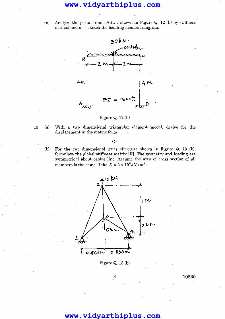
(b) Analyze. the portal frame ABeD shown in Figure Q. 12 (b) by stiffness method and also sketch the bending moment diagram .
. 4-h\..
A D
Figure Q. 12 (b)
13. (a) With a two dimensional triangular element model, derive for the displacement in the matrix form
Or
(b) For the two dimensional truss structure shown in Figure Q. 13 (b), formulate the global stiffness matrix [K]. The geometry and loading are symmetrical about centre line. Assume the area of cross section of all members is the same. Take E = 2 X 10⁸ kN / m 2 •
Figure Q. 13 (b)
3 10230
www.vidyarthiplus.com
www.vidyarthiplus.com
www.vidyarthiplus.com
www.vidyarthiplus.com
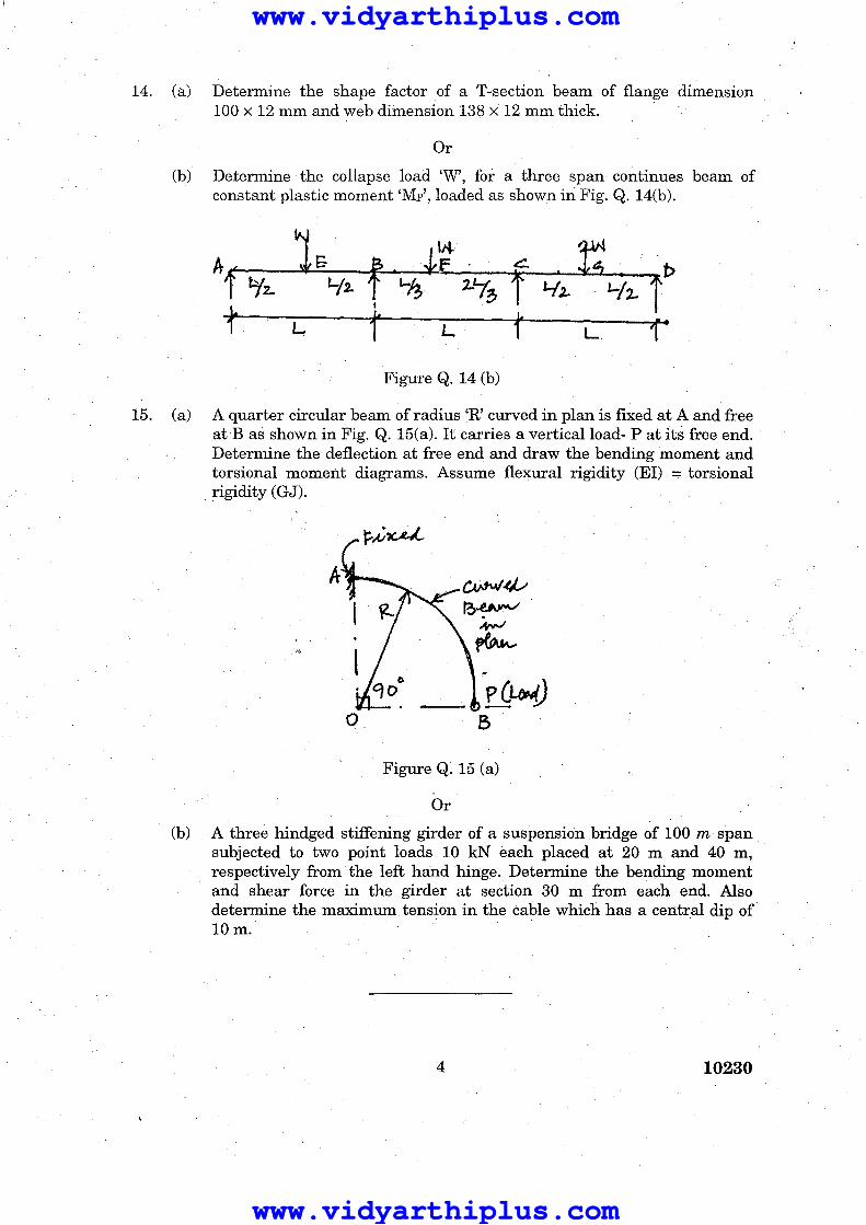
14. (a) Determine the shape factor of a T-section beam of flange dimension 100 x 12 mm and web dimension 138 x 12 mm thick.
Or
(b) Determine the collapse load 'W', for a three span continues beam of constant plastic moment 'Mp', loaded as shown in Fig. Q. 14(b).
f L. l'
Figure Q. 14 (b)
15. (a) A quarter circular beam of radius 'R' curved in plan is fixed at A and free at B as shown in Fig. Q. 15(a). It carries a vertical load- P at its free end. Determine the deflection at free end and draw the bending moment and torsional moment diagrams. Assume flexural rigidity (El) = torsional rigidity (GJ).
A_
o
Figure Q. 15 (a)
Or
(b) A three hindged stiffening girder of a suspension bridge of 100 m span subjected to two point loads 10 kN each placed at 20 m and 40 m, respectively from the left hand hinge. Determine the bending moment and shear force in the girder at section 30 m from each end. Also determine the maximum tension in the cable which has a central dip of 10m.
4 10230
www.vidyarthiplus.com
www.vidyarthiplus.com
www.vidyarthiplus.com
www.vidyarthiplus.com
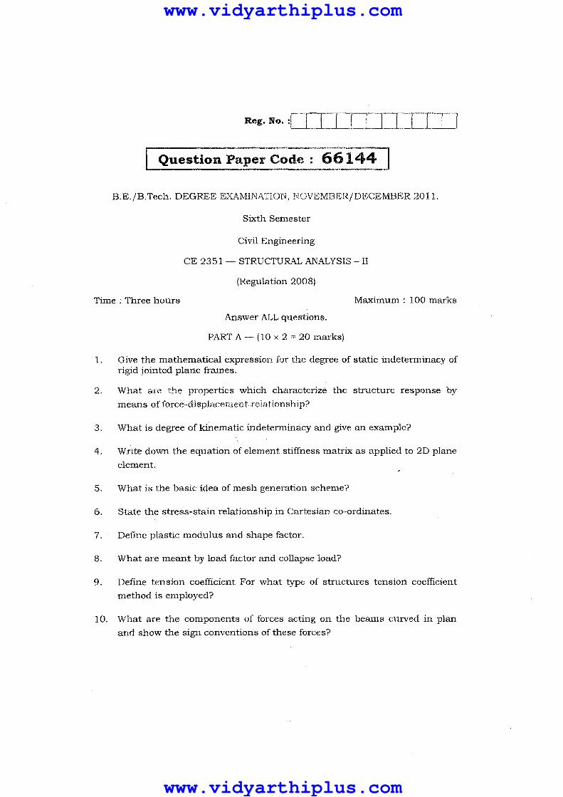
Reg. No. :1,---,-_,---,- [I In
B.E./B.Tech. DEGREE EXAMINATION, NOVEMBER/DECEMBER 2011.
Sixth Semester
Civil Engineering
CE 2351 - STRUCTURAL ANALYSIS - II
(Regulation 2008)
Time : Three hours Maximum: 100 marks
Answer ALL questions.
PART A - (10 x 2"" 20 marks)
1. Give the mathematical expression for the degree of static indeterminacy of rigid jointed plane frames.
2. What are the properties which characterize the structure response by
means afforce-displacement relationship?
3. What is degree of kinematic indetenninacy and give an example?
4. Write down the equation of element stiffness matrix as applied to 2D plane
element.
5. What is the basic idea of mesh generation scheme?
6. State the stress-stain relationship in Cartesian co-ordinates.
7. Define plastic modulus and shape factor.
8. What are meant by load factor and collapse load?
9. Define tension coefficient For what type of structures tension coefficient
method is employed?
10. What are the components of forces a.cting on the beams curved in plan
and show the sign conventions of these forces?
www.vidyarthiplus.com
www.vidyarthiplus.com

PART B - (5 x 16 == 80 marks)
11. (a) Analyze the continuous beam ABC shown in Fig, Q 11 (a) by flexibility matrix method and sketch the bending moment diagram.
h~~.fic ..... 4- '/'Vt-- I Z,.M.- I
e I ~ Cc"~sbA"f-
Fig. Q 11 (a)
Or
(b) Analyze the portal frame ABeD shown in Fig. Q 11 (b) by flexibility matrix method and sketch the bendi.."lg moment diagram.
Fig. Q 11 (b)
12. (a) Analyze the continuous beam ABC shown in Fig. Q12(a) by stiffness method and also draw the shear force diagram.
IJft.N .£.5' /J..N/M..-A~ . I'~'M I.~ fP:'Cla~c. ~L_ 3~ .-}--- .1' .
'3M.-E:':r. ::. ~bt '11 t-
Fig. Q12 (a)
Or
2 66144
www.vidyarthiplus.com
www.vidyarthiplus.com

(b) Analyze the portal frame ABeD shown in Fig. Q 12(b) by stiffness method and also draw the bending moment diagram.
:3pft ...
_k f :----
,. .. ~ h1 f..2.. 5'~--
F;y.~. p A
~:t::: c.c....sh:tt1\"" "
Fig. Q12 (b)
13. (aj Draw the typical finite elements. Explain with a triangular element model for displacement formulation.
Or
(b) Write a note on constant strain triangle. Explain in detail about the 4-nodded rectangular element to arrive the stiffness matrix.
14. (a) A simply supported beam of span 5m is to be designed for a UDL of 25 kN / m. Design a suitable I section using plastic theory, assuming yield stress in steel as fy = 250 N/mm2 •
Or
(b) Analyze a propped cantilever of length 'L and subjected to UDL of w/m length for the entire span and find the collapse load.
15. (a) A suspension bridge has a span 50 m with a 15 m wide runway. It is subjected to a load of 30 kN/m including self weight. The bridge is supported by a pair of cables having a central dip of 4m. Find the cross sectional area of the cable necessary if the maximum permissible stress in the cable material is not to exceed 600 MPa.
Or
3 66144
www.vidyarthiplus.com
www.vidyarthiplus.com

(b) A semi circular beam of radius 'R' in plan is subjected to UDL and simply supported by three columns spaced equally_ Derive the expression for bending moment and torsional moment at x-be a point on the beam making an angle a' with axis passing through the base of the circle,
4 66144
www.vidyarthiplus.com
www.vidyarthiplus.com

Reg. No.: 1 \ 1212101'6 1\ b 1:,:1; ls,,!:;T'''",",,'', .... t':'i'!1" \.t r.~~:~
'I Question Paper Code
B.E.IB.Tech. DEGREE EXAMINATION, APRILIMA¥Q<1l1
Sixth Semester
Civil Engineering
CE 2351- STRUCTURAL ANALYSIS - II
(Regulation 2008)
-~
~ -"'"4!:-
.~
~-
Time : Three hours Maximum: 100 marks
1.
2.
3. Define static indeterminacy.
4. Define flexibility of a structure.
5. State any two advantages of FEM. . :~~~.~ ~ ,:ft,'t. ':,:-. _.
D,efi:e plan;-~tress. 6.
7. :~ : ~_ ~." W· :i'. ;0>1"'" '" Whtlhs shape faCtor.:;,::
I·Sta"J;e upperbound."theorem. 'f'. (,' ~"
9. c,Qive aiily:two"~xainples of beams curved in plan.
10. WEite stress$s in suspended wires due to self weight. '!i.e; .J.
www.Vidyarthiplus.com
www.Vidyarthiplus.com

PART B - (5 x 16 = 80 marks)
11. (a) Analyse the continuous beam show in Fig .1 using force method.
100 kN
EI const
Fig. 1
Or
(b) Analyse the portal frame ABeD shown in Fig .2 using force method.
EI canst
Fig.2
12. (a) Analyse the continuous beam shown in Fig.3 using di;,;placement method.
240 kN
EI const
Fig.3
Or
2 11217
www.Vidyarthiplus.com
www.Vidyarthiplus.com

(b) Analyse the truss shown in FigA using displacement method.
FigA
13. (a) Develop the shape functions for an 8 noded brick element.
Or
(b) Construct the shape functions of a 2D beam element.
14. (a) Derive the shape factor for I section and circular section.
(b) Find the fully plastic momerit req!rtrt\Q. forCtb,~ frame shown in Fig.5 if all the members have same vahle o{,;,Mp • '\
T~~
2k~.] ................. , 2m .. . ,··4m
··:,'···.c .. 7'
6m
. "ii;·;'!·\'4,,,;;,,. .:'
'''Fr~.5 15. (a) A suspension cable is supported at two point "A" and "B" , "A" being one
metre above "B". The distance AB being 20m. The cable is subjected to 4 loads of 2kN, 4kN, 5kN and 3kN at distances of 4m, 8m, 12m and 16m
,respectively from "A". Find the maximum tension in the cable, if the dip of the cable at point of application of first load is 1m with respect to level at A. Find. also the length of the cable.
Or
(b) Derive the expressions for BM, SF and TM in a semicircular beam simply supPdt-ted oni,'three supports equally spaced.
,,5:."_ ",,=-
3 11217
/
www.Vidyarthiplus.com
www.Vidyarthiplus.com