TABLE OF CONTENTS · 2011-01-14 · TABLE OF CONTENTS Table of Contents .....1 List of Figures...
108
TABLE OF CONTENTS Table of Contents ...............................................................................................................................1 List of Figures ....................................................................................................................................4 61-2A Transverse Base Length of Wheel Load..........................................................................4 61-2B Cross Section of Multi-Beam Bridge...............................................................................4 61-2C Patch Loading – Simple Span ..........................................................................................4 61-2D Moment and Reaction Influence Lines for Point C .........................................................4 61-2E Moment Influence Lines for Point B ...............................................................................4 61-2F Calculation of Factored Moments ....................................................................................4 61-2G Strip Method Design (Typical Deck Reinforcement) ......................................................4 61-2H Cross Section of Haunched Concrete Slab Bridge ..........................................................4 61-3A Punching Shear Failure Mechanism in Concrete Deck ...................................................4 61-3B Interpretation of Effective Length S for Empirical Deck Design ....................................4 61-3C Empirical Design (Typical Deck Reinforcement) ...........................................................4 61-3D Additional Steel in End Zone for Skew Greater than 25 ...............................................4 61-4A Plan of Screeds ................................................................................................................4 61-4B Fillet Dimensions for Steel Beam ....................................................................................4 61-4C Fillet Dimensions for I-Beam, Box Beam, and Bulb-Tee Beam .....................................4 61-4D Precast Deck Panels on Bridge with Sag Vertical Curve ................................................4 61-4E Combinations of Skew Angle and Span Length/Bridge Width Ratios ............................4 61-4F Typical Pour Diagram (Continuous Prestressed Concrete Beams) ..................................4 61-4G Typical Pour Diagrams (Continuous Steel Beams or Plate Girders) ...............................4 61-4H Modular Expansion Joint .................................................................................................4 61-4I Modular Expansion Joint (Field Splice)............................................................................4 61-5A Deck Overhang Treatments (Superelevated Structure) ...................................................4 61-5B Overhang Dimensions......................................................................................................4 61-5C Calculation of Factored Moments ....................................................................................4 61-5D Barrier Reinforcement Position .......................................................................................4 61-5E Interaction Diagram for Combined Bending and Axial Load ..........................................4 61-5F Moment Diagram for Determining Cut-Off Point ...........................................................4 61-5G Length of Additional Bars in Deck Overhang .................................................................4 61-5H Suggested Transverse Edge Beam Details (Bulb-Tee Beam) .........................................4 61-5I Suggested Transverse Edge Beam Details (AASHTO I-Beams)......................................4 61-5J Suggested Transverse Edge Beam Details (Steel Plate Girder) ........................................4 61-5K Suggested Alternate Transverse Edge Beam Details (Steel Plate Girder) ......................4 61-5L Suggested Alternate Transverse Edge Beam Details (Bulb-Tee Beam, AASHTO I- Beams, and Steel Plate Girder) ..............................................................................................4 61-5M Calculation of Factored Moments ...................................................................................4 61-5N Reaction and Shear Influence Lines for Edge Beam .......................................................4 61-6A Bridge Railing Level Equivalency...................................................................................4 61-6B Bridge Railing Types .......................................................................................................5 61-6C Bridge Railing Pay Items .................................................................................................5 2010
Transcript of TABLE OF CONTENTS · 2011-01-14 · TABLE OF CONTENTS Table of Contents .....1 List of Figures...

TABLE OF CONTENTS
Table of Contents ...............................................................................................................................1
List of Figures ....................................................................................................................................4 61-2A Transverse Base Length of Wheel Load ..........................................................................4 61-2B Cross Section of Multi-Beam Bridge ...............................................................................4 61-2C Patch Loading – Simple Span ..........................................................................................4 61-2D Moment and Reaction Influence Lines for Point C .........................................................4 61-2E Moment Influence Lines for Point B ...............................................................................4 61-2F Calculation of Factored Moments ....................................................................................4 61-2G Strip Method Design (Typical Deck Reinforcement) ......................................................4 61-2H Cross Section of Haunched Concrete Slab Bridge ..........................................................4 61-3A Punching Shear Failure Mechanism in Concrete Deck ...................................................4 61-3B Interpretation of Effective Length S for Empirical Deck Design ....................................4 61-3C Empirical Design (Typical Deck Reinforcement) ...........................................................4 61-3D Additional Steel in End Zone for Skew Greater than 25 ...............................................4 61-4A Plan of Screeds ................................................................................................................4 61-4B Fillet Dimensions for Steel Beam ....................................................................................4 61-4C Fillet Dimensions for I-Beam, Box Beam, and Bulb-Tee Beam .....................................4 61-4D Precast Deck Panels on Bridge with Sag Vertical Curve ................................................4 61-4E Combinations of Skew Angle and Span Length/Bridge Width Ratios ............................4 61-4F Typical Pour Diagram (Continuous Prestressed Concrete Beams) ..................................4 61-4G Typical Pour Diagrams (Continuous Steel Beams or Plate Girders) ...............................4 61-4H Modular Expansion Joint .................................................................................................4 61-4I Modular Expansion Joint (Field Splice) ............................................................................4 61-5A Deck Overhang Treatments (Superelevated Structure) ...................................................4 61-5B Overhang Dimensions ......................................................................................................4 61-5C Calculation of Factored Moments ....................................................................................4 61-5D Barrier Reinforcement Position .......................................................................................4 61-5E Interaction Diagram for Combined Bending and Axial Load ..........................................4 61-5F Moment Diagram for Determining Cut-Off Point ...........................................................4 61-5G Length of Additional Bars in Deck Overhang .................................................................4 61-5H Suggested Transverse Edge Beam Details (Bulb-Tee Beam) .........................................4 61-5I Suggested Transverse Edge Beam Details (AASHTO I-Beams) ......................................4 61-5J Suggested Transverse Edge Beam Details (Steel Plate Girder) ........................................4 61-5K Suggested Alternate Transverse Edge Beam Details (Steel Plate Girder) ......................4 61-5L Suggested Alternate Transverse Edge Beam Details (Bulb-Tee Beam, AASHTO I-
Beams, and Steel Plate Girder) ..............................................................................................4 61-5M Calculation of Factored Moments ...................................................................................4 61-5N Reaction and Shear Influence Lines for Edge Beam .......................................................4 61-6A Bridge Railing Level Equivalency...................................................................................4 61-6B Bridge Railing Types .......................................................................................................5 61-6C Bridge Railing Pay Items .................................................................................................5
2010

61-6D Typical Reinforcement in Bridge Sidewalk ....................................................................5
Chapter Sixty-one ..............................................................................................................................6
61-1.0 BACKGROUND ...................................................................................................................6 61-1.01 Bridge Deck and Superstructure Type ...........................................................................6 61-1.02 Crack Control in Beam-Supported Concrete Deck Slab ...............................................7
61-1.02(01) External Restraint..............................................................................................7 61-1.02(02) Internal Restraint ...............................................................................................8 61-1.02(03) Shrinkage ..........................................................................................................8 61-1.02(04) Residual Temperature Strain .............................................................................8
61-1.03 Delamination Control in Concrete Deck .......................................................................9
61-2.0 STRIP METHOD ..................................................................................................................9 61-2.01 Description.....................................................................................................................9 61-2.02 Application of the Strip Method to a Composite Concrete Deck ..................................10
61-2.02(01) Patch Loading ...................................................................................................11 61-2.02(02) Live-Load Moment at Point C ..........................................................................14 61-2.02(03) Live-Load Moment at Point B ..........................................................................15 61-2.02(04) Deck Reinforcing Steel .....................................................................................16 61-2.02(05) Crack Control ....................................................................................................18 61-2.02(06) Minimum Reinforcing Steel .............................................................................19
61-2.03 Longitudinal Application of Strip Method ....................................................................20
61-3.0 EMPIRICAL DESIGN OF CONCRETE DECK ..................................................................21 61-3.01 Application of Empirical Design ...................................................................................21 61-3.02 Behavior of Plates and Plate-Like Components ............................................................21 61-3.03 Criteria for Empirical Design ........................................................................................22
61-4.0 BRIDGE-DECK DESIGN ....................................................................................................24 61-4.01 General Requirements ...................................................................................................24 61-4.02 Dimensional Requirements for Concrete Deck .............................................................25
61-4.02(01) Screed Elevations for Cast-in-Place Concrete Deck .........................................25 61-4.02(02) Fillet Dimensions for Steel Beams or Girders ..................................................26 61-4.02(03) Fillet Dimensions for Concrete Beams .............................................................27
61-4.03 Forms for Concrete Deck ..............................................................................................27 61-4.03(01) Precast Deck Panels ..........................................................................................27 61-4.03(02) Permanent Metal Forms ....................................................................................28 61-4.03(03) Overhangs .........................................................................................................28
61-4.04 Skewed Deck .................................................................................................................28 61-4.05 Shear Connectors and Vertical Ties ..............................................................................29 61-4.06 Deck Joints ....................................................................................................................29
61-4.06(01) Longitudinal Open Joint ...................................................................................29 61-4.06(02) Construction Joint .............................................................................................30 61-4.06(03) Expansion Joints ...............................................................................................32
61-4.07 Drainage Outlets ............................................................................................................33
2010

61-5.0 MISCELLAENOUS STRUCTURAL ITEMS ......................................................................33 61-5.01 Longitudinal Edge Beam ...............................................................................................34 61-5.02 Deck Overhang ..............................................................................................................34
61-5.02(01) Design Methods ................................................................................................34 61-5.02(02) Deck Overhang Design .....................................................................................35
61-5.03 Transverse Edge Beam ..................................................................................................48 61-5.03(01) Design of Transverse Edge Beam .....................................................................48 61-5.03(02) Transverse-Edge-Beam Design Example .........................................................49
61-5.04 Design of Bridge Railing ...............................................................................................54
61-6.0 BRIDGE RAILING ...............................................................................................................54 61-6.01 Test Level Selection ......................................................................................................54
61-6.01(01) TL-2 ..................................................................................................................55 61-6.01(02) TL-4 ..................................................................................................................55 61-6.01(03) TL-5 ..................................................................................................................56 61-6.01(04) TL-6 ..................................................................................................................56 61-6.01(05) Making Test Level Determination ....................................................................56
61-6.02 Bridge-Railing-Type Selection ......................................................................................58 61-6.02(01) INDOT Standard Railings.................................................................................58 61-6.02(02) FHWA-Approved Non-INDOT-Standard Railings ..........................................58 61-6.02(03) Considerations if Sidewalk Present ..................................................................59
61-6.03 Bridge-Railing-Design Details ......................................................................................59 61-6.03(01) Superelevated Bridge Deck...............................................................................59 61-6.03(02) Barrier Delineators ............................................................................................59
61-6.04 Bridge-Railing Transition ..............................................................................................60 61-6.04(01) Type ..................................................................................................................60 61-6.04(02) Location ............................................................................................................60
61-6.05 Pedestrian Railing ..........................................................................................................62 61-6.06 Bicycle Railing ..............................................................................................................62
61-6.06(01) Bicycle Path ......................................................................................................62 61-6.06(02) Other Facility ....................................................................................................62
61-7.0 BRIDGE APPURTENANCES ..............................................................................................63 61-7.01 Outside Curbs ................................................................................................................63 61-7.02 Center Curb or Median Barrier ......................................................................................63 61-7.03 Lighting .........................................................................................................................63 61-7.04 Traffic Signals ...............................................................................................................64 61-7.05 Utilities Located on an INDOT Bridge .........................................................................64
2010

LIST OF FIGURES Figure Title 61-2A Transverse Base Length of Wheel Load 61-2B Cross Section of Multi-Beam Bridge 61-2C Patch Loading – Simple Span 61-2D Moment and Reaction Influence Lines for Point C 61-2E Moment Influence Lines for Point B 61-2F Calculation of Factored Moments 61-2G Strip Method Design (Typical Deck Reinforcement) 61-2H Cross Section of Haunched Concrete Slab Bridge 61-3A Punching Shear Failure Mechanism in Concrete Deck 61-3B Interpretation of Effective Length S for Empirical Deck Design 61-3C Empirical Design (Typical Deck Reinforcement) 61-3D Additional Steel in End Zone for Skew Greater than 25 61-4A Plan of Screeds 61-4B Fillet Dimensions for Steel Beam 61-4C Fillet Dimensions for I-Beam, Box Beam, and Bulb-Tee Beam 61-4D Precast Deck Panels on Bridge with Sag Vertical Curve 61-4E Combinations of Skew Angle and Span Length/Bridge Width Ratios 61-4F Typical Pour Diagram (Continuous Prestressed Concrete Beams) 61-4G Typical Pour Diagrams (Continuous Steel Beams or Plate Girders) 61-4H Modular Expansion Joint 61-4I Modular Expansion Joint (Field Splice) 61-5A Deck Overhang Treatments (Superelevated Structure) 61-5B Overhang Dimensions 61-5C Calculation of Factored Moments 61-5D Barrier Reinforcement Position 61-5E Interaction Diagram for Combined Bending and Axial Load 61-5F Moment Diagram for Determining Cut-Off Point 61-5G Length of Additional Bars in Deck Overhang 61-5H Suggested Transverse Edge Beam Details (Bulb-Tee Beam) 61-5I Suggested Transverse Edge Beam Details (AASHTO I-Beams) 61-5J Suggested Transverse Edge Beam Details (Steel Plate Girder) 61-5K Suggested Alternate Transverse Edge Beam Details (Steel Plate Girder) 61-5L Suggested Alternate Transverse Edge Beam Details (Bulb-Tee Beam, AASHTO I-Beams, and Steel Plate Girder) 61-5M Calculation of Factored Moments 61-5N Reaction and Shear Influence Lines for Edge Beam 61-6A Bridge Railing Level Equivalency
2010

61-6B Bridge Railing Types 61-6C Bridge Railing Pay Items 61-6D Typical Reinforcement in Bridge Sidewalk
2010

CHAPTER SIXTY-ONE
BRIDGE DECKS 61-1.0 BACKGROUND
61-1.01 Bridge Deck and Superstructure Type
The LRFD Specifications encourages the integration of the deck with the primary components of the superstructure by means of either composite or monolithic action. The deck sometimes becomes the superstructure, or the deck may disappear as a separate structural component, leading to confusion in definition. The method of categorizing bridge superstructures described herein is based essentially on the type of modeling required for analysis. The categories for which the superstructure-type designations, as provided in Figure 59-3B, are applied are as follows: 1. Category I: Thin Deck
. This includes each deck made of concrete, steel, wood, or a combination thereof, usually not exceeding 1 ft depth, supported by straight- or curved-line components, and which is treated as follows:
a. designed as strips to satisfy the specified limit state for a single line of wheels; b. designed empirically by satisfying a specified set of conditions; or c. selected from the manufacturer’s table, whose content is verified as required by
the LRFD Specifications. 2. Category II: Deck System
. This consists of type G3, G4, L1, or L2.
3. Category III: Slab Bridge
. This consists of type A or B.
4. Category IV: Spine Beams
. This consists of type C, D1, D2, or H.
5. Category V: Multiple Beams
. This consists of type E1, F, G1, G2, I, J, L3, or L4.
6. Category VI: Multiple Boxes
. This consists of type E2 or K.
This Chapter addresses the design of Categories I and II only. No separate decks exist in Category III. The deck parts in Category IV are designed either in accordance with Category I, by satisfying minimum requirements, or by special design provisions (e.g., long cantilever overhangs). The deck parts in Category V are designed in accordance with Category I. The same applies to Category VI, except where deck-force effects are determined using two-dimensional analyses.
2010
LRFD Specifications Article 9.5.5 mandates that a deck withstand the vehicular collision force effects generated by the yield resistance of a barrier railing. For that reason, the railings are treated as a part of the deck. The LRFD Specifications also promotes the use of structurally-continuous composite railings, as described herein in conjunction with perimeter beams. The problem of discontinuity in the deck caused by drainage facilities is also discussed. For the design of the deck, by using either the strip method or the empirical method, open box beams, either flared or rectangular in cross section, may be considered as two separate beams. Open box beams include superstructure type C, D2, E2, H, or K.
61-1.02 Crack Control in Beam-Supported Concrete Deck Slab
A bridge deck which was designed in accordance with superseded AASHTO bridge design specifications almost never fails under loads. If failure occurs, it is invariably precipitated by non-load type actions such as the disintegration of the concrete as a material due to freeze-thaw, carbonation, solar radiation, toxic chemicals, etc., and the cracking of the concrete due to corrosion of metallic elements in the concrete. There are many parameters that may potentially affect cracking, and there appears to be not any one parameter that acts as the primary source of distress. Cracking is the cumulative effect of unfavorable variations in a few key parameters, and only these will be discussed herein. For a discussion on all of the parameters, see NCHRP Report 380. Cracking is caused by tensile stresses exceeding the tensile strength of the concrete. This discussion addresses only those tensile stresses which are caused by restrained volumetric changes such as the following: 1. shrinkage of concrete; 2. residual hydration temperature strains; or 3. corrosion of reinforcing steel. Restraint to volumetric changes can be either external or internal, as described below. 61-1.02(01) External Restraint External restraint is usually the result of composite action, either voluntary or involuntary, between the concrete deck and the beams, in which the shortening of the deck due to shrinkage and residual temperature strains is resisted by the beam. The action develops tensile force in the
2010

deck, an equal compressive force in the beam, and moments in both because of the eccentric application of this force. The maximum tensile stress occurs at the bottom of the deck. 61-1.02(02) Internal Restraint The incompatibility between concrete and reinforcing steel has often been ignored, namely that, by resisting shrinkage strains, the steel sets up tensile stresses in the concrete. A tensile ring develops around the bar and, if the bar is transverse, this annular stress is additive to the tensile stress caused by the external, longitudinal restraint. 61-1.02(03) Shrinkage The total shrinkage value particular to a given concrete mix design cannot be influenced by the method of construction. The cracks usually appear very soon after concrete placement. Such cracking often depends on the rate of shrinkage, the rate of gaining tensile strength, and the plastic creep capacity of the concrete. There is a lack of information available on the interaction among these three parameters. However, it is reasonable to assume that the application of wet curing and the retention of moisture by means of impervious sheeting decelerate both the rate of shrinkage and the loss of plasticity without impeding the gain in tensile strength. 61-1.02(04) Residual Temperature Strain Hydration of the cement is a chemical process which produces heat and, thus, a rise in the temperature of the deck. During this process, the concrete solidifies at a temperature higher than that of the beam. Once the concrete cools off, tensile strains are set up in the deck, which are the same as, in their effects, and are additive to, shrinkage strains. The hydration temperature is further increased by solar radiation if present. The temperature can effectively be controlled as follows: 1. reduction in cement content, as the hydration heat is directly proportional to the amount
of cement; and 2. the method and duration of curing.
61-1.03 Delamination Control in Concrete Deck
Although the issue of crack control relates primarily to a beam-supported, cast-in-place concrete deck slab, the problem of delamination is potentially present in every concrete deck. In the presence of air and moisture, reinforcing steel corrodes, and the corrosion process is accelerated
2010

by salts. The corrosion product (i.e., rust) has a much larger volume than the steel consumed, resulting in large spalled areas at the top of the deck. The methods used to decelerate the rate of corrosion and control deck cracking are described below. 1. Coated Reinforcing Steel
. This retards corrosion of reinforcing steel.
2. Waterproofing and Asphaltic Overlay
. Most waterproofing cannot be made perfect and, by trapping moisture, it is counterproductive. Its usage will be permitted only if approved by the Production Management Division’s Structural Services Office manager.
3. Concrete Bridge Deck Overlay (Microsilica or Latex-Modified)
. Because each is virtually impervious, it performs well on an old deck, but is expensive.
4. Concrete Cover
. Increased depth of cover delays, but does not prevent chlorides from eventually reaching the reinforcing steel.
5. Post-Tensioning
. This minimizes cracking.
6. Cathodic Protection
. This retards corrosion of reinforcing steel.
7. Bar Size
. Smaller-diameter bars for the same steel cross-sectional area provide better crack-size control.
61-2.0 STRIP METHOD
61-2.01 Description
For the design of the deck, LRFD Specifications Article 4.6.2 provides a new version of the strip method that had been the basis of the previous editions of the AASHTO Standard Specifications for Highway Bridges. The strip method is based on a structural simplification in which the deck is replaced by a parallel set of continuous beams running in the primary direction of the deck, supported by unyielding supports with the span lengths taken as the beam spacings, and the vehicular loading represented by a single line of wheel loads acting on this beam. The effective width of this beam (i.e., the strip width, E) is determined from LRFD Table 4.6.2.1.3-1. In analyzing a transverse strip, the following procedure may be applied. 1. Determine the number of design lanes in accordance with LRFD Article 3.6.1.1.1.
2010

2. Position the loads on the strip. The following applies.
a. only full axles of 32 kip (16 kip per wheel) are to be used; b. the center-to-center distance of the wheels is 6 ft; c. the center of the wheel does not become closer than 1 ft to the edge of the
roadway boundary (curb or railing); d. the axle is positioned to obtain extreme moments irrespective of the position of
the design or traffic lanes; e. the wheel loads may be modeled as concentrated loads or as patch loads; and f. if patch loads are used, calculate the transverse base length of a wheel, as shown
in Figure 61-2A, by adding twice the distance between the neutral axis of the deck and the top of the deck to the specified transverse footprint. This rule is based on a conservative 45-deg angle of load distribution.
Calculate the maximum moments by considering multiple lane loads and multiple presence factors. For negative moment, see LRFD Article 4.6.2.1.6 for determination of the critical design section. Live-load moments for the strip method may be obtained from LRFD Table A4-1 in lieu of calculating them. These moments may be 15% to 20% more conservative than those calculated using the method described herein.
61-2.02 Application of the Strip Method to a Composite Concrete Deck
The strip method is appropriate for each type of supporting members, including AASHTO I-beams, spread box beams, steel beams, or concrete beams with T-shaped flanges, by using Equation 61-2.1 with the appropriate values of Bp
. The following will apply to the application of the strip method of analysis.
1. Reinforcing Steel
. It is not necessary to use the same size or the same spacing of reinforcing steel in the top and bottom of the bridge deck in the primary direction. For constructability, the top and bottom bars should be of the same size, and the spacing of bars in one mat should be a multiple of the other.
2. Moment Influence
. Either calculate or obtain moment influence lines from textbooks for four-tenths span and support points.
3. Shear Effects
. By using the strip method, an 8-in. deck is designed for flexure, and shear effects can be neglected.
2010

Figure 61-2B illustrates the cross section of a typical beam-slab bridge with four beams spaced at 10 ft, a minimum-depth 8-in. concrete deck, and concrete railings. The deck overhang width of 4.5 ft shown in Figure 61-2B is intended only for use in the design examples in Sections 61-2.0 and 61-5.0. For criteria for deck overhang width limitations, see Section 61-5.02. A dead load of 35 lb/ft2
should be considered as a future wearing surface. The 36-ft width clear roadway accepts three 12-ft width travel lanes. Influence lines, as shown in Figures 61-2D and 61-2E, are drawn for Points C and B. Influence lines can readily be obtained in discrete form from standard tables for continuous beams. Influence-line ordinates are shown at 0.1L intervals for this example. Figure 61-2D also shows the influence line for reaction at Point C.
61-2.02(01) Patch Loading Maximum bending moment at a point is higher due to a concentrated load as compared to the same load spread over some distance. A simple approximation is derived to account for the patch loading effect. 1. Positive Moment
. The patch loading is distributed over a tire width of 1.67 ft (LRFD Article 3.6.1.2.5) plus the depth of the deck (LRFD Article 4.6.2.1.6). Because positive-moment influence lines have sharp peaks at the point of interest and ordinates drop off rapidly, using a patch loading can result in significantly lower design moments than the concentrated wheel load. Using a simple span, an approximation will be developed which simplifies the application of a patch loading. Extension to a continuous member is also approximate, because the pertinent influence lines are curved.
Consider a simple beam having a span length L. Assume that it is desired to compute the maximum positive moment at the 0.4 point of the span due to a patch loading of width BL, such that B is a fraction. From Figure 61-2C, it is desired to locate the patch load, measured with X as a fraction of the base length, to cause the maximum bending moment. The bending moment at the 0.4 point will be the uniform (patch) loading times the area of the influence line subtended by the load: A1 + A2 in Figure 61-2C. To maximize the bending moment, the fraction X should maximize the sum of the areas A1 + A2
.
The ordinate ( )XBLLY -= 4.06.01 The (trapezoidal) area 2222
1 3.024.0 LXBBXLA -= Likewise, the ordinate ( )XBBLY +-= 6.04.02 The (trapezoidal) area 222222222
2 2.04.02.024.024.0 LXBXLBLBBXLBLA -+--= Summing the areas yields the following: 22222222
21 5.04.02.024.0 LXBXLBLBBLAA -+-=+
2010

Taking the derivative of total area with respect to the variable X and setting it to zero to find the maximum area yields the following:
( )04.0 222221 =-=
+ XLBLBdX
AAd
Solving for X yields X = 0.4.
This position of the patch loading will yield maximum moment at the 0.4 point. The maximum positive moment at the 0.4 point is the patch uniform load P/BL times the influence area A1 + A2
. This results in the following:
( )22222222max 5.04.02.024.0 LXBXLBLBBL
BLPM -+-=
Setting X = 0.4 for the maximum moment yields ( )BLLPM 12.024.0max -=
This first term is the moment that results from the concentrated wheel load being applied at the point in question (0.4 point). The second term is a correction resulting from the load being spread out over a width BL.
This result can be generalized, because the proportion X is directly related to the point in question. For the 0.5 point, X = 0.5, etc. Without showing all the steps, for maximum moment at the center, with X = 0.5, the equation becomes the following:
Mmax ( )BLLP 125.025.0 -= at 0.5 point
This leads to a convenient approximation for patch load maximum moments. Place the concentrated load at the maximum influence line ordinate and correct with the term PBL/8, where BL is the length of the patch loading. The result at the 0.4 point is not quite correct and the error increases as the point is farther away from the midspan. For design purposes, however, we are concerned with points near midspan and the error is minimal.
For continuous spans, this approximation should be used as a reasonably accurate simplification to the arduous process that would be required with the curved influence lines.
8
POLL
PBMM -=
Where: ML = adjusted design positive moment for live load
2010

MOL
P = concentrated wheel load at the point of interest = positive moment using concentrated wheel loads
BP
= patch load base length (1.67 ft plus deck depth)
2. Negative Moment
. A similar formula for deck design negative moment can be derived, but with slightly different terminology and background. Influence lines for support moments are typically curved and the use of patch loads does not change the design moment significantly.
Instead, the negative moments are computed at the center of the support and then corrected to the actual design section using Equation 61-2.2. The second (correction) term in the equation represents the change in moment from the center of support to the design section. Rather than assuming a hypothetical concentrated reaction, the reaction is assumed to be uniformly distributed over a length of twice the distance from the center of support to the design section (BN/2). The correction term is then the area of the shear diagram between the center of support and design section. This is a triangle with base length BN/2 and ordinate equal to shear at the support. The area of the triangle is then VBN/4. Because the shear on either side of the reaction is approximately half of the support reaction, the correction to the moment becomes RBN
/8. Because the support moment is negative, the formula is similar to Equation 61-2.1, except that the sign of the correction is positive, which reduces the design moment.
Summarizing, the maximum negative moment and accompanying reaction at the center of support are computed using concentrated wheel loads. LRFD Article 4.6.2.1.6 specifies the location of the negative moment design section as follows:
a. at the face of support for concrete box beams; b. one-quarter of the flange width from centerline of support for steel beams; or c. one-third of the flange width, not to exceed 1.25 ft from the centerline of support,
for precast I-shaped or T-shaped concrete beams. The negative design moment can then be computed as follows:
8
NOLL
RBMM += (Equation 61-2.2)
Where: ML
M = adjusted design negative moment for live load
OL
R = support reaction due to concentrated wheel loads = support negative moment using concentrated wheel loads
BN
= twice the distance from centerline of support to negative design section
2010
61-2.02(02) Live-Load Moment at Point C For maximum negative moment, two situations are examined. Two wheels (single truck, with a multiple presence factor of 1.20) are placed in the most critical position for negative moment at the center of the support. The design moment is then computed at the critical section by correcting the negative support moment using Equation 61-2.2. A similar process is followed using four wheels (side-by-side trucks, with a multiple presence factor of 1.00). The minimum spacing between adjacent truck axles is 4 ft. As a guideline for computation of design negative moment, a single truck will control for a beam spacing less than approximately 9.5 ft. For beam spacing greater than approximately 12 ft, the spacing between adjacent axles (two trucks) will be greater than the minimum of 4 ft. The design negative moment is computed by correcting the live-load moment at the centerline of support to the critical design section. Because dead loads contribute only a small component to the total deck design moment, the (conservative) correction of dead-load moment to the critical section is not made. Figure 61-2D shows the wheel positions and moment influence line particulars for Point C. The critical position for the single truck places the first wheel 3.25 ft to the left of Point C and the second wheel 2.75 ft to the right of Point C. Moment and reaction influence ordinates for this position are obtained by linear interpolation between 1/10 point ordinates, resulting in the following: MOL
= 16.0 (-0.96 – 0.72) = -26.9 kip-ft
R = 16 (0.886 + 0.835) = 27.5 kip Equation 61-2.2 will be used to compute the negative design moment. For an AASHTO Type IV I-beam, the flange width is 1.67 ft.
11.1367.12 =÷
øö
çèæ=NB ft
1.238/)11.1(5.279.26 -=+-=LM (single truck) The critical position for two trucks places the first wheel 7.5 ft left of Point C, the second wheel 1.5 ft left, the third wheel 2.5 ft right, and the fourth wheel 8.5 ft right, resulting in the following: MOL = 16.0 (-0.61 – 0.60 – 0.70 – 0.23) = -34.2 kip-ft
2010

R = 16.0 (0.390 + 0.988 + 0.851 + 0.146) = 38.0 kip ML
= -34.2 + 38.0 (1.11)/8 = -28.9 kip-ft (two trucks)
The multiple presence factors should be considered in concluding which situation gives the maximum live load moment. Multiplying the single truck result by 1.2 gives a design moment of -27.7 kip-ft, meaning that two trucks give a slightly larger design moment (28.9 > 27.7). Therefore, in terms of the wheel load P = 16 kip, and ML
= -1.81P.
61-2.02(03) Live-Load Moment at Point B The moment influence line for Point B is shown in Figure 61-2E. The 0.4L point is selected as the point more likely to develop maximum positive moment. A single truck axle with a multiple presence factor of 1.20 is used for design, because the influence line ordinates in the third span (where a second truck would be placed) are only 5% of those in the first span. Because the multiple presence factor is 1.00 for two trucks, the contribution of the second truck must be 20% more than the single truck for this situation to control, which is obviously not true. The critical wheel position places one wheel at the 0.4 point, with the other over support C. Using Equation 61-2.1 as follows:
8
POLL
PBMM -=
where: MOL
B = P (2.01). (2.01 is influence ordinate at wheel)
P
such that
= 20 in. + 8 in. (depth of deck) = 28 in. = 2.33 ft
PPPM L 72.18
)33.2(01.2 =-=
61-2.02(04) Deck Reinforcing Steel LRFD Specifications Table 4.6.2.1.3-1 specifies the strip widths for a concrete deck as follows:
a. For positive moment, E(+)
b. For negative moment, E= 26.0 + 6.65 = 26.0 + 66 = 92 in. = 7.67 ft
(-)
= 48.0 + 3.05 = 48.0 + 30.0 = 78 in. = 6.5 ft
The unit weight of concrete is taken as 0.15 kip/ft3. The weight of the future wearing surface is 35 lb/ft2. To account for the additional concrete weight in the corrugations of steel forms, an additional dead load of 15 lb/ft2 is included. Dead loads per 1-ft wide strip are as follows:
2010

Concrete Slab: (0.67)(0.15) = 0.10 kip/ft Steel Form Effect: (0.015)(1.0) = Total Concrete DL = 0.115 kip/ft
0.015 kip/ft
Future Wearing Surface: 0.035 kip/ft The dead load due to a 1-ft length of 2.75-ft-height concrete railing with cross-sectional area of 2.55 ft2
is as follows:
(2.55)(0.15) = 0.383 kip/ft Maximum factored force effects per 1-ft width are summarized in Figure 61-2F. Required reinforcement can be computed using the following:
c
yssysu fb
fAaadfAM
¢=÷
øö
çèæ -=
85.0;
2j
combining as follows:
÷÷ø
öççè
æ¢
-=c
yssysu fb
fAdfAM
70.1j
or: ( ) 2270.170.1 yscsysuc fAfbdfAMfb jj -¢=¢ Setting up a quadratic for As
as follows:
0)70.1(70.1
22 =
¢+÷
÷ø
öççè
æ ¢-
y
cu
y
scss f
fbMf
dfbAA
j
This can be solved by using the quadratic formula as follows:
2
70.1;
70.1
y
uc
y
sc
fMfb
Cf
dfbB
j
¢=
¢=
Which results in the following:
2
42 CBBAs
--= (Equation 61-2.3)
Where:
y
cs
ffbd
B'70.1
= 2
70.1
y
us
fMbd
Cj
=
cf ¢ = specified concrete strength (ksi) b = width of unit strip (in.)
2010

ds
f = distance between the center of steel and the outer compressive fiber (in.)
y
M = yield strength of reinforcing steel (ksi) u
j = specified resistance factor: 0.9 = factored moment per unit width (kip-in.)
For an 8-in. slab with specified minimum cover, 0.5-in. wearing surface, allowing for 1 in. cover on the bottom steel and 2 in. on the top steel and assuming a No. 5 bar, the following apply. 1. For positive moment. ds
(+)
2. For negative moment, d = 8 – 0.5 – 1.0 – 0.3125 = 6.2 in.
s(–)
3. f¢ = 8 – 0.5 – 2.0 – 0.3125 = 5.2 in.
c = 4 ksi and fy
= 60 ksi.
For positive moment:
( )( )( ) 2.76.1460
2.671270.1 inB ==
( )( )( )( )( )
42 .20.5
609.01.11871270.1 inC ==
As = 0.36 in.2
/ft
For negative moment:
( )( )( ) 2.38.1260
2.571270.1 inB ==
( )( )( )( )( )
42 .14.6
609.02.13971270.1 inC ==
As = 0.52 in.2
/ft
61-2.02(05) Crack Control The negative moment steel should be checked for crack control under Service I Limit State in accordance with LRFD Specifications Article 5.7.3.4. The value of Z will be computed and compared to the limiting value of 130 kip/in. (severe exposure) assuming that the exact amount of negative steel is furnished with No. 5 bars. The actual steel placement should provide at least that area, meaning that the calculation is valid. ( ) 3/1AdfZ csa=
2010

Where: fsa
d = stress in steel at service limit state
c
A = area of concrete surrounding the bar (2d = concrete depth from center of bar to extreme tension fiber
c
The maximum clear cover for computation of d ´ bar spacing for this situation)
c
is 2 in.
Using No. 5 bars to provide the negative steel area of 0.52 in2
/ft results in a spacing of 7.2 in.
dc
= 2 in. (cover) + 0.25 in. (bar radius) = 2.25 in.
A = 2dc (spacing) = 2(25)(7.2) = 32.4 in
2
The service limit moment for Point C is 6.76 kip-ft/ft (value from Figure 61-2F, with load factor equal to 1.00). Using elastic theory, the location of the neutral axis for negative moment, kd
, can be found by solving the quadratic equation as follows:
)(2
)( 2
dsd kdAn
kb-=
with:
83645
00029===
c
s
EE
n
The quadratic becomes: )52)(52.0)(8(2
)(12 2
dd k
k-=
The solution yields kd
= 2.27 in.
The moment arm between compression and tension forces is (d – kd
/3) = 4.44 in.
jdAM
fs
wsa = ( )( ) ksif sa 1.35
44.452.012.81
==
The maximum stress to be used is 0.6fy
or 36 ksi.
( )( )[ ] ./1464.3225.21.35 3/1 inkipZ == This value is slightly (12%) above the limit of 130 kip/in. If a practical bar spacing of 6 in. is chosen, the calculated Z becomes 118 kip/in., which is acceptable.
2010

61-2.02(06) Minimum Reinforcing Steel LRFD Specifications Article 9.7.3.2 determines the minimum longitudinal bottom steel as a percentage of the transverse bottom reinforcement as follows:
%67220£=
Sg (Equation 61-2.4)
Where: S = effective span in feet per LRFD Article 9.7.2.3. (Distance between flange tips
plus flange overhang.) For an AASHTO Type IV I-beam, the flange width is 20 in. and the web thickness is 8 in., resulting in a flange overhang of 6 in. Therefore, S = 120 – 20 + 6 = 106 in. = 8’-10” and g = 75%. The 67% limit governs, requiring As = (0.67)(0.36) = 0.24 in2
/ft.
Minimum longitudinal top reinforcement is determined by using LRFD Article 5.10.8, which provides shrinkage and temperature steel requirements. The minimum area of steel, As
, is determined as follows:
y
gs f
AA
75.0= (Equation 61-2.5)
Where: As = Minimum area of steel, each mat, each direction (in2
f)
y
= yield strength of steel (ksi)
Because the bottom reinforcement is already provided, the gross sectional area, Ag
, will be interpreted as the top half of the slab, as follows:
( )( ) 05.060
475.0==sA in2
/ft
Summary of Steel: Transverse Bottom: 0.36 in2
Transverse Top: 0.052 in/ft 2/ft (0.62 in2
Longitudinal Bottom: 0.24 in/ft if crack control is enforced)
2
Longitudinal Top: 0.05 in/ft
2
/ft
Figure 61-2G provides typical deck reinforcement for the strip method for analysis.
2010

61-2.03 Longitudinal Application of Strip Method
Where a deck or deck system is supported by cross-beams (floor beams) or by substructure components, the primary direction of structural action is longitudinal. The cross section of a reinforced-concrete slab bridge is shown in Figure 61-2H. The width of the slab is set to be greater than the clear-roadway width as required. The span lengths of the continuous slab bridge are 57.75 ft, 72.0 ft, and 57.75 ft. The strip width, in inches, with more than one lane loaded, is determined as follows:
LNWWLE 0.1244.10.84 11 £+= (Equation 61-2.6)
Where: E = ( )( ) .1520.3975.5744.10.84 in=+ = 12.67 ft E is less than the limiting value of 12.0 W/NL
L = 13 ft; therefore, E = 12.67 ft.
1 = The lesser of the shortest span length or 60 ft; therefore, L1
W = 57.75 ft.
1 = The lesser of the slab width or 60 ft; therefore, W1
W = Physical edge-to-edge width of bridge (ft). = 39.0 ft.
NL
= Number of design lanes as specified in LRFD Article 3.6.1.1.1.
The longitudinal force effects may be reduced for a skewed bridge in accordance with LRFD Article 4.6.2.3. The design for all loadings should be in accordance with LRFD Article 3.6.1.2.1, including the lane load. 61-3.0 EMPIRICAL DESIGN OF CONCRETE DECK
61-3.01 Application of Empirical Design
The empirical design method may be used to design a deck that is supported on beams or girders if the following conditions, in addition to those specified in LRFD Article 9.7.2.4, are met. 1. The design-year AADT is less than 5000. 2. The design-year ADTT is less than 500. 3. The skew angle is less than or equal to 20 deg. The above criteria apply to either a bridge rehabilitation project (which includes a new deck), or a new bridge. If empirical design is used, a memorandum should be sent to the Production Management Division director so that a database can be kept of each such bridge.
2010
61-3.02 Behavior of Plates and Plate-Like Components
If the inelastic response of the deck includes cracking as in a concrete slab, or separation of laminates as in a wood deck, it results in a local rise in the position of the neutral axis which, in turn, leads to internal arching. Physical testing on concrete decks has demonstrated that close to 80% of the wheel load is being carried in the arching mode at ultimate limit state, that the failure mode is not one of flexure but punching shear, and that the resistance at ultimate is at least five times the value calculated by applying flexural theory. Figure 61-3A illustrates the actual failure mode of a reinforced concrete deck, which is the basis of the empirical design provided in the LRFD Specifications. As shown, failure is initiated at a perimeter line surrounding the tire footprint, which is either circular or elliptical in plan, under a combination of compression and shear. The location of failure initiation is not at the center of the wheel load where the lateral compression is a maximum, because therein the shear is zero. The presence of the vertical load creates tri-axial compression which is highly favorable in terms of resistance. In addition, the angle ά between the failure surface and the horizontal is rather shallow, usually 3:1, indicating the presence of large in-plane compressive forces. Because of the cover requirement, the position of the top steel is too low to allow participation in the failure initiation zones, and the angle ά too small to permit either the top or the bottom steel to meaningfully share in resisting the wheel load. At this angle, the effectiveness of horizontal steel is only 33% in comparison with vertical steel which would have an effectiveness, if used, of 100%. Under testing, a locally unreinforced concrete deck indicates a loss of resistance not exceeding 25%, an indication that flexural reinforcement contributes very little to the load-carrying capacity of a concrete deck slab. The deck should be made fully continuous over the superstructure unit for the application of the empirical design. The lack of discontinuities, either voluntary or involuntary, and the general tightness of the deck provide the lateral confinement which should be considered the most important feature in the design of a plate-type bridge deck.
61-3.03 Criteria for Empirical Design
The complexity and sophistication that may be required in the computations when dealing with in-plane forces in the inelastic phase is deemed to be beyond the normal scope of design. Instead, the LRFD Specifications provides a set of criteria that must be satisfied if the empirical design is applied. The criteria are repeated herein with commentary added as appropriate. 1. Cross-frames or diaphragms are used throughout the cross section at lines of support.
2010

2. For cross sections involving torsionally stiff units, such as individual separated box beams, either intermediate diaphragms between the boxes are provided at a spacing not to exceed 25 ft, or the need for supplemental reinforcement over the webs to accommodate transverse bending between the box units is investigated and reinforcement is provided if necessary.
3. The supporting components are made of steel and/or concrete. 4. Deck is fully cast in place and water cured. The intent of this requirement is to exclude a
deck in which either the reinforcing steel or the concrete, or both, are discontinuous. 5. The deck is of uniform depth, except for haunches at girder flanges and other local
thickening. This requirement reflects that all research work was carried out on a slab of uniform depth.
6. The ratio of effective length to design depth does not exceed 18.0 and is not less than 6.0.
This is perhaps the most important requirement, by which flatness of the internal arch is limited. Figure 61-3B interprets the effective length of deck, S, for various support conditions such as AASHTO I-beams, box beams, steel I-beams, or concrete bulb-tee beams.
7. Core depth of the slab is not less than 4 in. The intent of this requirement is to provide
an adequate internal moment arm for the slab. 8. The effective length, as specified in Article 9.7.2.3, does not exceed 13.5 ft. This
requirement reflects upon the maximum size of specimens tested. If effective length, S, exceeds 11 ft, the depth of slab should be increased according to Item 6 above. If S is less than 3.5 ft, the strip method of design should be used.
9. The minimum depth of slab is not less than 7 in., excluding a sacrificial wearing surface.
The minimum depth of slab is 8 in., which includes a 0.5-in. sacrificial wearing surface. 10. There is an overhang beyond the centerline of the outside girder of at least five times the
depth of the slab; this condition is satisfied if the overhang is at least three times the depth of the slab, and a structurally continuous concrete barrier is made composite with the overhang. The intent is to provide a tension ring of sufficient width at the edge to resist internal arching forces between the exterior and the first interior beam. The concrete railing shown on the INDOT Standard Drawings is considered a structurally continuous concrete barrier.
2010

11. The specified 28-day strength of the deck concrete is not less than 4000 psi. Tests have indicated insensitivity of the deck to compressive strength. The intent is to provide a reasonably resilient and non-permeable deck.
12. Deck is made composite with the supporting structural components. Tests have indicated
a definite enhancement of lateral confinement due to composite action. A minimum of two shear connectors at 2-ft centers should be provided in the negative-moment region of a continuous steel beam or girder superstructure. The requirements of LRFD Article 6.1.0.3 should also be satisfied. For prestressed concrete beams, the use of stirrups extending into the deck should be taken as sufficient to satisfy this requirement. Stay-in-place concrete formwork should not be permitted in conjunction with empirical design. A special provision is required for deleting the option of allowing the use of precast deck panels. The LRFD Specifications requires four layers of isotropic reinforcement. For each of the two top layers, the minimum steel area is 0.18 in2/ft, and for each of the bottom two layers, the minimum steel area is 0.27 in2
/ft. The recommended minimum reinforcing-bars sizes and spacings for constructability and crack control are as follows:
1. Two top layers, each #4 at 1’-0” 2. Two bottom layers, each #5 at 1’-0” Figure 61-3C provides the typical deck reinforcement for the empirical design. All reinforcement shall be straight bars except where hooks are required. The additional longitudinal reinforcement provided in the deck in the negative moment regions of a continuous beam or girder type bridge, beyond that required for isotropic reinforcement according to LRFD Article 9.7.2.5, need not be matched in the transverse direction. A skewed deck tends to develop torsional cracks in the end zones of the deck. To control crack size, LRFD Specifications Article 9.7.2.5 specifies that the minimum reinforcement be doubled in the end zones of the deck, but not at intermediate piers, with a skew in excess of 25 deg. As shown in Figure 61-3D, end zones, as bounded by dotted lines, are defined for the additional transverse and longitudinal steel. The additional steel should be present at both ends. In Section 61-3.02, the role of arching effects is discussed and the significance of tightness is stated. The question of tightness (i.e., effective confinement of the compressive zone) is relative to cracking due to shrinkage or negative moments in the supporting beams where the slab is in tension. The entire superstructure should be designed and constructed with the objective of minimizing cracking in the deck.
2010

61-4.0 BRIDGE-DECK DESIGN
61-4.01 General Requirements
1. Thickness
. The depth of a reinforced concrete deck should not be less than 8 in.
2. Reinforcement
. The bottom reinforcement cover should be 1 in. The top reinforcement cover should be 2.5 in. The primary reinforcement should be on the outside.
3. Sacrificial Wearing Surface
. The top 0.5 in. of the bridge deck should be considered sacrificial and should not be included in the structural design or as part of the composite section.
4. Class of Concrete
. Class C concrete should be used.
5. Concrete Strength
. The specified 28-day compressive strength of concrete should not be less than 4 ksi.
6. Reinforcing-Steel Strength
. The specified yield strength of reinforcing steel should not be less than 60 ksi.
7. Epoxy Coating
. All reinforcing steel in both top and bottom layers should be epoxy coated for a bridge deck supported on beams.
8. Sealing
. All exposed roadway surfaces, concrete railings, and outside copings should be sealed from drip bead to drip bead. The underside of the copings and the exterior face of outside concrete beams should also be sealed.
9. Length of Reinforcing Steel
. The maximum length of individual reinforcing-steel bars should be 40 ft. All reinforcing-bar splice lengths should be shown on the plans.
10. Truss Bars
. Truss bars should not be used in a concrete deck supported on longitudinal stringers or beams.
11. Placement of Reinforcing Steel
. For a skew greater than 25 deg, transverse reinforcing steel should be placed perpendicular to the beams. For a skew of 25 deg or less, reinforcement should be placed parallel to the skew.
61-4.02 Dimensional Requirements for Concrete Deck
2010

61-4.02(01) Screed Elevations for Cast-in-Place Concrete Deck Screed elevations should be furnished to ensure that the gutters, or the edges of deck on a bridge without curbs, will be at the proper final elevations. Screed elevations are required for a beam or girder bridge, or a continuous reinforced-concrete slab bridge on a superelevation transition. Screed elevations, if not shown on the plans, should be provided in tabular form on letter-size sheets. This information should include a diagram or table showing the elevations at the top of the concrete deck that are required before the concrete is placed. Elevations should be shown for both curblines, or sidewalk gutter lines, and crown of the roadway and above all beam or girder lines for the full length of the bridge, at all bearings, and at a maximum of 10-ft intervals. Elevations at mid-span are optional and need be shown only for short spans where the nearest 10-ft station may be some distance from the point of maximum deflection. Elevations at splice points will be required. A structure on a horizontal or vertical curve, or in a superelevation transition, will require additional elevation points to define the concrete-deck screed elevations. A sufficient number of screed elevations must be provided so that the contractor is not forced to interpolate or make assumptions in the field. The designer should furnish all elevation points to allow the proper construction and finishing of the deck. Figure 61-4A illustrates the locations of screed elevations for a bridge deck with curbs and sidewalks. Screed elevations should be determined using the following criteria. 1. Screed lines should be established parallel to the skew and at approximately 10-ft
intervals longitudinally within each span. 2. Transversely, screed elevations should be provided at both copings, curb lines, at the
centerline of each beam, and at the profile grade and longitudinal construction joints. 3. Deflections should be computed on the basis of beam continuity at the time of deck
placement. 4. Use an elastomeric bearing pad deflection of 5% of the elastomer thickness. 5. Screed elevations should be rounded to the nearer 0.25 in.
2010

61-4.02(02) Fillet Dimensions for Steel Beams or Girders Figure 61-4B illustrates fillet dimensions for steel beams or girders. The following will apply to the use of the Figure. 1. Control dimension Y should be established so that the theoretical bottom of deck clears
the thickest and widest top flange plate by 0.75 in. to compensate for the allowed tolerance for beam camber, or so that the bottom reinforcement clears the field splice plate by 0.5 in., whichever controls.
2. Dimension Y should be shown on deck details to the nearest 0.10 in. 3. Control dimension Y should be established immediately after the top flange-plate and
splice-plate sizes have been determined. The maximum slope of deck should be used to set dimension Y.
4. Dimension Y should be held constant at each beam or girder, where possible, throughout
the structure. 5. Once established, dimension Y should be used for all elevation computations such as
bridge seats, top of splice elevations, etc. 61-4.02(03) Fillet Dimensions for Concrete Beams Figure 61-4C illustrates fillet dimensions for concrete beams. The basic requirement is to have the top of beam not higher than 0.75 in. below the bottom of slab at the center of the span. This allows the actual beam camber to exceed the calculated value up to 1.75 in. before the top of the beam would begin interfering with the deck steel. Dimension A at the center of the span represents an input item required for prestressed-beam-design computer programs and can be determined as follows:
÷øö
çèæ+=
275.0 eWA
Where: W = beam top flange width, in. e = deck crown or superelevation slope The following may occur. 1. The critical location of the 0.75-in. minimum fillet will most often occur at the center of
each span.
2010

2. The critical location of the 0.75-in. minimum fillet will sometimes occur at the ends of
the beam, for example, where either the residual beam camber is negative or where the residual beam camber allowance is less than the crest-vertical-curve effect.
61-4.03 Forms for Concrete Deck
Contractor options regarding the use of permanent metal forms and precast concrete deck panels are provided in the INDOT Standard Specifications. The following criteria apply to forms for a concrete deck. 61-4.03(01) Precast Deck Panels Precast prestressed-concrete deck panels may be used as an alternative to removable wooden forms for certain types of prestressed-concrete I-beam structures and only where the deck is designed using the strip method. If a prestressed-concrete I-beam bridge is located wholly or partially within a sag vertical curve or a superelevation transition, precast-concrete deck panels may be used if the additional Class C concrete deck thickness, t, as shown on Figure 61-4D, is 3 in. or less. For such a prestressed-concrete I-beam bridge, a note should be placed on the deck slab details as follows: Precast prestressed concrete deck panels may be substituted for removal forms on
this structure. If deck panels are allowed for a multiple-span continuous structure, only the top mat of longitudinal steel should be used to satisfy negative moment tensile forces. LFRD Specifications Article 9.7.4.3.1 recommends that the depth of stay-in-place concrete forms should not be less than 3.5 in. However, based upon demonstrated satisfactory performance, a depth of 3 in. or 2.5 in., as shown on the INDOT Standard Drawings may be used. 61-4.03(02) Permanent Metal Forms Metal stay-in-place forms can be used to support the deck between beams regardless of whether the strip method or empirical deck design method is used. Plan details should be prepared assuming that removable forms will be used. The INDOT Standard Specifications describe acceptable methods of attaching the floor form support angles to the beams. Attachment details should not be shown on the plans. For a steel beam or girder
2010

structure, a detail showing the location of tension and reversal areas in the top flange should be included in the plans, as welded attachments will not be permitted in these areas. 61-4.03(03) Overhangs Removable forms must be used to support deck overhangs and may be used to support the deck between girders.
61-4.04 Skewed Deck
Skew is defined as the angle between the end line of the deck and the normal drawn to the longitudinal centerline of the bridge at that point. The two end skews can be different. In addition to skew, the behavior of the superstructure is also affected by the span-length-to-bridge-width ratio. The LRFD Specifications implies that the effects of a skew angle not exceeding 25 deg can be neglected, but only for a bridge with a relatively large span-length-to-bridge-width ratio. Figure 61-4E shows four combinations of skew angles 25 deg and 50 deg, and length-to-width ratios of 3:1 and 1:3. Both the 50-deg skew and the 1:3 length-to-width ratio are considered extreme values, but this often occurs where the deck constitutes the top slab of a culvert. It can be judged visually that both combinations with 25-deg skew may be orthogonally modeled for design. LRFD Specifications Article 9.7.1.3 Commentary provides valid arguments supporting the limit of 25 deg concerning the direction of transverse reinforcement. It suggests that placing the transverse reinforcement parallel to a skew larger than 25 deg will create a structurally undesirable situation in which the deck is essentially unreinforced in the direction of principal stresses. It is required that, for skew larger than 25 deg, the transverse reinforcement must be placed perpendicular to the beams. The combination of 50-deg skew and length-to-width ratio of 1:3, as indicated in Figure 61-4E, produces a layout such that if the deck is a cast-in-place concrete slab without beams, the primary direction of structural action is one being perpendicular to the end line of the deck. Because of the geometry of the layout, consideration should be given to placing the primary reinforcement in that direction and fanning it as appropriate in the side zone. With that arrangement, the secondary reinforcement could then be placed parallel to the skew, thus regaining the orthogonality of the reinforcement as appropriate for this layout.
61-4.05 Shear Connectors and Vertical Ties
2010
Based on the LRFD Specifications, composite action between the deck and its supporting components should be ensured where it is technically feasible. The design of stud or channel shear connectors for steel sections and vertical ties for concrete beams or girders is discussed in the LRFD Specifications. See Chapters Sixty-two, Sixty-three, and Sixty-four for criteria. Shear connectors and vertical ties between the deck and its supporting members should be designed for force effects calculated on the basis of full composite action, whether or not that composite action is considered in proportioning the primary members.
61-4.06 Deck Joints
61-4.06(01) Longitudinal Open Joint A longitudinal open joint is not required in a concrete bridge deck with a width of 90 ft or less. If a deck width of wider than 90 ft is required, a longitudinal open joint may be used, or a longitudinal closure pour not less than 2 ft wide, may be used. Transverse-steel lap splices should be located within the longitudinal closure pour. Such a joint should remain open as long as the construction schedule permits transverse shrinkage of the deck concrete to occur. The bearings supporting a superstructure that has a deck width exceeding 50 ft should be capable of allowing movement in the transverse direction due to temperature and shrinkage movements. 61-4.06(02) Construction Joint A construction joint creates planes of weakness that frequently cause maintenance problems. The use of deck construction joints is discouraged and their number should be minimized. The contractor, however, has the option of requesting additional joints if the number or locations shown on the plans are too restrictive. 1. Longitudinal Construction Joint
.
a. Usage. Construction joints need not be used on a deck having a constant cross section where the width of pour is less than 65 ft. This applies if the constant cross section is rotated along the length of the deck, and the angular breaks within the cross section remain constant. Where the angular breaks within the cross section are variable, as in the runout length of a superelevation transition, a construction joint should be provided. Longitudinal construction joints will also be required on a deck with phased construction.
b. Location. The following applies.
2010

(1) Where a construction joint is required, it should preferably be placed along the edge of a traffic lane. A joint which is close to a curb may be placed up to 1 ft outside the traffic lane.
(2) A joint should not be located over a beam flange, unless phased
construction dictates otherwise.
(3) The joint locations should limit the maximum width of pour to 50 ft to 55 ft.
c. Transverse Reinforcing Steel. The lengths of transverse reinforcing bars should
be selected so bar laps do not appear within a longitudinal construction joint. 2. Transverse Construction Joint
.
a. Steel Beam or Girder Structure. Concrete may be placed continuously on a deck requiring less than 260 yd3
of concrete. A bridge deck that is poured integrally with the end bents may usually be placed with one pour.
For a longer structure that exceeds the pour-volume limitation of 260 yd3
, an alternative may be considered in which the deck length is subdivided into segments near the points of final dead load contraflexure, with segments in positive flexure placed first and those in negative flexure last.
b. Prestressed-Concrete Structure. A prestressed-concrete beam bridge made continuous for live load only should be treated such that transverse construction joints located 2.5 ft on each side of the pier centerline should be shown on the plans. The short deck segment and diaphragm over the support provide continuity for live load in the superstructure after the previously-poured center regions of the deck have been poured as simple-span loads.
c. Location. Where used, transverse joints should be placed parallel to the
transverse reinforcing steel. 3. Diaphragms
. For a prestressed-concrete beam bridge with a cast-in-place deck, the LRFD Specifications requires concrete diaphragms at the bearings. These diaphragms should be poured at the same time as the deck.
4. Steel Structure. A steel superstructure with short end spans relative to the adjacent interior span may be subject to uplift at the end bent during the deck pour. This may occur where the far end span is 60% or less of the adjacent interior span. Where this occurs, and if objectionable, a required transverse construction joint should be placed in
2010
the far end span and a terminal portion of the end span poured first to counterbalance the uplift. The deck may then be poured from the opposite end forward in the usual manner. The designer should investigate the effects of the deck pouring sequence, including its effect on camber, screed elevations, and stresses.
5. End Bents
. The simply-supported end of a short end span may experience uplift under live load. A counterweight may be poured near the end of the span to counterbalance the uplift, or positive hold-down devices may be installed. The details of counterweights or tie-downs should be shown on the plans. Integral end bent concrete should be considered as a counterweight.
6. Pour Diagrams
. Figure 61-4F illustrates the pour diagrams for a continuous, prestressed-concrete beam structure. The plans should include a note similar to that shown on Figure 61-4F, revised as necessary. Figure 61-4G illustrates the pour diagrams for a continuous steel beam or girder structure.
61-4.06(03) Expansion Joints Indiana is considered to have a cold climate for the purpose of expansion-joint design. See AASHTO LRFD Specifications Table 3.12.2.1-1 for temperature-range values to use to calculate joint movements due to temperature. The following provides criteria for the use of expansion joints. 1. Compression Seal Type BS
. This type of seal has not performed well in the past and should not be used as an expansion joint.
2. Expansion Joint Sealing System
. This joint may be used on a bridge to be rehabilitated.
3. Strip Seal Class SS
.
a. Details. The details are shown on the INDOT Standard Drawings. b. Expansion Length. This expansion joint may be used for an expansion length up
to 400 ft. The plans must designate the expansion length for the contractor’s use of the Joint Setting Table shown in the INDOT Standard Drawings, which is dependent upon the ambient temperature while the deck is being poured (see Item c). Therefore, the designer must compute the expansion length in feet for each joint location and indicate this value on the General Plan at each joint location.
2010

c. Width of Opening. This joint is designed by the manufacturer to accommodate a minimum of 4 in. of movement. The width of the joint opening at installation depends upon the ambient temperature while the deck is being poured, and the expansion length of the structure at the joint location.
This joint opening width is shown in the Joint Setting Table in the Standard Drawings for a range of ambient temperatures and expansion lengths.
4. Modular Type M
.
a. Details. Figures 61-4H and 61-4 I illustrate typical schematic details for this joint.
b. Length of Expansion. The modular joint is used only where the anticipated expansion movement exceeds the length that can be accommodated by a class SS expansion joint. For an expansion movement greater than 4 in., a modular expansion joint is recommended.
c. Splices. Where practical, a modular joint should be full length with no field
splices across the roadway width. If a field splice is required for traffic continuity, the support beams should be spaced at a maximum of 2 ft. See Figure 61-4 I, Section A-A.
d. Elastomeric Seal. The elastomeric seal will be one piece across the roadway
width, regardless of traffic continuity considerations and the presence of a field splice in the steel armor. See the INDOT Standard Specifications for more information.
61-4.07 Drainage Outlets
Chapter Thirty-three discusses the hydrological and hydraulic analyses for a bridge deck. This includes the methodologies for calculating the flow of water on the bridge and for determining the necessary spacing of drainage outlets to prevent the spread of water on the deck from exceeding the acceptable limits. Additional design criteria and details of drainage outlets on a bridge deck and closed drainage systems are also provided in Chapter Thirty-three. To make deck drainage facilities operationally effective and insensitive to blocking by debris or ice, they should be large in size and few in number as suggested by the LRFD Specifications. See Article 2.6.6 for more information. Where practical, the use of roadway drain type SQ is preferred over roadway drain type OS because it does not accumulate debris as easily. Locations of roadway drains types SQ and OS should always be checked to verify that they clear the top
2010

flange of the outside beam or girder. The large drainage facility, however, creates a discontinuity in the deck which should be considered. A deck acting monolithically is not too sensitive to this, and for a drainage facility whose maximum dimension does not exceed 1.33 ft, no additional deck reinforcement is required. If the facility interrupts a main bar of a steel grid deck, the facility should be framed, and the frame should support the interrupted element. 61-5.0 MISCELLAENOUS STRUCTURAL ITEMS
61-5.01 Longitudinal Edge Beam
The LRFD Specifications does not require the presence of side longitudinal edge beams but permits the utilization of solid concrete barriers as structural parts of the deck or deck system. Railing-type barriers consisting of wood, steel, or concrete beams and posts offer only negligible structural contribution, so the usable advantages relate exclusively to solid-concrete wall and safety-shape types. However, the structural contribution of concrete appurtenances to the deck should not be considered for the strength or extreme-event limit states per LRFD Specifications Article 9.5.1, because other than immediate repair of an accidentally-damaged railing will result in temporary, yet unacceptable, understrength of the bridge. The structural contribution of the concrete railing should only be considered for the service or fatigue-and-fracture limit states. If the bridge railing is structurally discontinuous (i.e., beam and post), a longitudinal edge beam may be required.
61-5.02 Deck Overhang
Additional top steel to resist the collision load transmitted through a railing may be required in a large overhang designed by the strip method and will generally be required for a slab designed by the empirical method. In accordance with LRFD Specifications Article 4.6.2.1.3, the width in inches of the primary strip for a cast-in-place concrete deck is 45 + 10X, where X is the distance from load to point of support. 61-5.02(01) Design Methods Bridge-deck overhang-width restrictions apply only to a multi-girder type superstructure, as follows: 1. Empirical Deck Design Method
. LRFD Specifications Article 9.7.2.4 defines the overhang width as the distance from the centerline of the outside beam to the outside coping of the deck. The overhang-width criteria are as follows:
2010

a. not less than 3.0 times the slab depth with a continuous concrete bridge railing or type TX railing present; or
b. not less than 5.0 times the slab depth with another type of bridge railing present.
2. Empirical or Strip Design Method
. Overhang width is defined as the distance from the centerline of the exterior beam to the face of the deck coping. The suggested overhang-width criteria are as follows:
a. not more than 0.45 times the beam spacing;
b. not more than 0.85 times either of the following: (1) web depth for a steel beam or girder bridge; (2) beam depth for a concrete I-beam or a concrete bulb-tee beam bridge;
c. not more than 5 ft.
The overhang width for a prestressed-concrete box-beam bridge should not exceed 2 ft
from the edge of the outside beam. If type OS deck drains are to be used on a beam or girder structure, the minimum overhang width should be 1.75 ft plus one-half the flange width. The deck-drain locations should always be checked to verify that the drains clear the top flange. 61-5.02(02) Deck Overhang Design For curved deck copings with reference to segmentally spaced straight beams, the above limits on maximum width should be interpreted as the average width within a span. A 0.75-in., half-round drip bead should be placed 6 in. in from the edge of the coping. The depth of the outside coping should be a minimum of 8 in. Once a coping depth is selected, it should be maintained over the full length of the superstructure along that coping. Because of the geometry of construction jacks used to support an overhang, the bottom of the coping should be made flush with the underside of the top flange of a steel structure. The bottom of the coping may be sloped to match the slope of the top of deck, or at least be made level. The depth of the outside coping for a superelevated deck should be greater than the minimum 8-in. deck thickness. The coping depth will generally be dimension Y minus the superelevation rate times half the flange width at the low side, or, plus the superelevation rate times half the flange width at the high side. See Figure 61-5A. The slope of the bottom of the overhang will
2010

then be parallel to the top of the deck. The coping depth selected at each coping should be maintained over the full length of the superstructure along that coping. For a curved-deck layout, the distance from the centerline of the girder to the face of the coping along both copings should be shown in a Coping Offset Diagram. These offsets should be shown at 10-ft intervals measured along the centerline of the girder. The offset at all break points of the girders should also be shown. For the design of a deck overhang with a cantilever not exceeding 6 ft from the centerline of the exterior girder to the face of a structurally continuous concrete barrier, LRFD Specifications Article 3.6.1.3.4 permits replacement of concentrated wheel loads with a line load of 1 kip/ft intensity, located 1 ft from the face of the railing. Thus, an effective longitudinal distribution of wheel loads and an ease of design is realized. If other railings are used, the strip method may be applied. The design approach, as reflected by the LRFD Specifications, is that the vehicular collision loads are not specified and that the overhangs are designed for the maximum inelastic force effects which can be generated and transmitted by the railing resisting the vehicular impact. LRFD Commentary CA13.4.2 states, the crash testing program is oriented toward survival and not necessarily the identification of the ultimate strength of the railing system. This could produce a railing system that is significantly over-designed leading to the possibility that the deck overhang is also over-designed. The computed railing capacity will be far greater than the required capacity. Designing the overhang for full railing capacity will result in an extremely conservative section that is not in accordance with observed field behaviors. Based on observations of impacted bridge railings, an overhang designed according to previous AASHTO bridge-design specifications shows the desired behavior that the overhang does not fail if a railing failure occurs due to a collision. Accordingly, the overhang should be designed for a collision force of 25% greater than the required capacity, which results in a design approximating present satisfactory practice. There is a normal concentration of force effects in the end zone of the railing, and the deck may need strengthening therein. An extension of the end beam (hidden or otherwise) to the railing may be necessary to strengthen the overhang. LRFD Equations A13.3.1-3 and A13.3.1-4 can be used to check the railing strength for impact near the end of the railing and to compute the magnitude of the loads to be transferred to the deck overhang and the need for extra top deck reinforcement. The deck overhang is a cantilever slab that supports the barrier railing and can be designed independently of the deck spans. Sufficient negative moment reinforcement must be provided for the design conditions. The reinforcement must be adequately anchored into the first deck span.
2010

Two limit states are used for design, Strength I and Extreme Event II. LRFD Article A13.4.1 also requires the deck overhang to be designed for the vertical forces specified in the Article A13.2 Extreme Event limit state. However, for a continuous concrete railing, this never controls. The strength-limit state considers vertical gravity loads and will only govern the design if the cantilever span is very large. The extreme-event-limit state considers horizontal forces caused by the collision of a vehicle with the railing and will usually govern the deck overhang design. The deck overhang design for the bridge shown in Figure 61-2B is described as follows: 1. Strength I Limit State. The design negative moment is computed at the critical section,
which is one-third of the beam flange width from the center of support. For an AASHTO type IV I-beam, the flange width is 1.67 ft. The overhang is a non-redundant member (hR = 1.05), and an operational importance factor of hi
= 1.05 will be used. Accordingly, the load modifier factor is as follows:
h = hd hR hi
= (1.0)(1.05)(1.05) = 1.10.
Figure 61-5B shows the dimensions relating to the overhang. Figure 61-5C provides the moment computations. The dead load of the 8-in. thick concrete deck equals (0.67)(0.15) or 0.10 kip/ft2
.
Where a structurally continuous concrete barrier railing is to be used (see Section 61-5.04), the live loading for the cantilever slab specified in LRFD Specifications Article 3.6.1.3.4 can be used. The dynamic load allowance of 1.33 and the multiple presence factor for a single truck of 1.20 are included in the load factor column. Including the load modifier factor, the design negative moment per foot is as follows:
ftkipM neg -== 66.8)87.7(10.1
As will be shown, the Extreme Event II Limit State (vehicular collision with railing) governs the negative reinforcement required over the exterior support.
2. Extreme Event II Limit State
. The forces to be transmitted to the deck overhang due to a vehicular collision with the railing are determined from a strength analysis of the railing. Design forces applied to the railing for this example are from LRFD Article A13.2, Test Level (TL) 4. This test level is acceptable for the majority of applications on a high-speed highway, freeway, expressway, or Interstate highway with a mixture of trucks and heavy vehicles. The railing must be strong enough to resist these forces. The deck overhang is designed to be stronger than the railing so that collision repairs can be made to the railing rather than the deck itself.
2010

The concrete bridge railing, 2.75-ft height (see the INDOT Standard Drawings), is used in the example. The following equations from the LRFD Specifications can be used to check the railing strength away from the end of the wall and to compute the magnitude of the loads to be transferred to the deck overhang.
÷÷ø
öççè
æ++÷÷
ø
öççè
æ-
=H
LMHMM
LLR cc
wbtc
w
2
882
2 (Equation A13.3.1-1)
( )c
wbttc M
HMMHLLL
++÷
øö
çèæ+=
822
2
(Equation A13.3.1-2)
Where: Rw
L = total transverse resistance of the railing (kip)
c
L = critical wall length of yield line failure pattern (ft)
t
M = longitudinal length of distribution of impact force (ft) b
= moment strength (in addition to Mw
M
) of beam at top of wall, if present (kip-ft)
w
M = moment strength of wall about its vertical axis (kip-ft/ft)
c
H = height of railing (ft) = moment strength of cantilevered wall about horizontal axis (kip-ft/ft)
For the chosen barrier railing, Mb
The materials’ yield stresses are as follows: = 0 and H = 2.75 ft.
cf ¢ = 4 ksi fy
= 60 ksi
3. Moment Strength of Railing About Vertical Axis
. The moment strength about the vertical axis is dependent on the horizontal reinforcement in the railing. Both positive and negative moment strengths are computed, because the yield-line mechanism develops both types (LRFD Figure CA13.3.1-1). The railing thickness varies, so it is convenient to divide the railing into segments as shown in Figure 61-5D.
Segment 3 includes no reinforcement and does not contribute to the moment strength. The positive and negative moment strengths of Segment 1 are essentially equal, and the compressive-reinforcement contribution can be neglected as having minimal effect. The resistance factor j is taken as 1.0 for this situation (LRFD Article 1.3.2.1).
293.0)31.0(35.3 inNoAs ===
.9.63
8.40.44.38.12 indave =÷øö
çèæ ++
+=
2010

( )( )( )( ) in
bffA
ac
ys 71.023485.0
6093.085.0
==¢
=
÷øö
çèæ -=
21adfAM ysn jj
365271.09.6)60)(93.0(0.11 =÷
øö
çèæ -=nMj kip-in.
For Segment 2, the positive and negative moment strengths are slightly different. Both will be calculated and the average used in the strength computation. Designating positive moment as producing tension on the straight face, as follows:
231.05#1 inAs == .7.93.54.4 ind pos =+=
ina 78.0)7)(4(85.0
)60(31.0==
.173278.07.9)60)(31.0(0.1 inkipM npos -=÷
øö
çèæ -=j
For negative moment: indneg 1.83.58.2 =+=
.143278.01.8)60)(31.0(0.1 inkipM nneg -=÷
øö
çèæ -=j
The average value is as follows:
.1582
1431732 inkipM n -=
+=j
The total moment strength of the railing about the vertical axis is the sum of the strengths in the segments, as follows:
ftkipinkipHM w -=-=+= 6.43.523)158365(
4. Moment Strength of Railing About Horizontal Axis. The moment strength about the
horizontal axis is dependent on the vertical reinforcement in the railing. The yield lines that cross the vertical reinforcement cause tension in the (inside) sloping face of the railing. Therefore, only the negative moment strength need be calculated. The depth to the vertical reinforcement increases from the top to the bottom of the railing, and the moment strength increases accordingly. LRFD Commentary CA13.3.1 states that the
2010

value of Mc
used in the analysis should be the average of strengths along the railing height. For this situation, the average structural depth will be used to compute the average moment capacity. The vertical reinforcement on the tension side is #5 at 8 in., both for the barrier railing and the hairpin bars which tie the railing into the deck.
The development length of the hairpin bars should be considered prior to making the moment strength calculations, because the full strength of the bars may not be developed. From LRFD Article 5.11.2.1.1, the basic development length for a No. 16 bar is as follows:
inf
fAl
c
ybdb 625.11
4)60)(31.0(25.125.1
==¢
=
but not less than ftinfd yb 25.115)60)(625.0(4.04.0 ===
with modification factors of 1.2 for epoxy-coated bars and 0.8 because the bars are spaced more than 6 in. apart. Accordingly, the required development length is as follows:
ftinld 2.14.14)8.0()2.1(15 ===
The hairpin bar does not have a standard hook, however, the bar extension into the deck may be considered as part of the available development length. The available development length for the hairpin bar is then 8 in. – 2 in. + 13 in. = 19 in. = 1’-7”. The hairpin bars may be considered as fully developed. A width of 8 in. (equal to the bar spacing) will be used in the computations, and the moment will then be divided by 8 to obtain values per inch.
For Segment 1, the average railing thickness is 9.88 in. and the moment strength is as follows:
ind 6.72625.00.288.9 =--=
.68.0)8)(4(85.0)60)(31.0(
85.0in
fbfA
ac
ys ==¢
=
./.9.16268.06.7
8)60)(31.0(0.1
2ininkipad
bfA
M yscl -=÷
øö
çèæ -=÷
øö
çèæ -=
jj
2010

For Segments 2 and 3, the structural depth to the hairpin steel varies linearly. The average railing thickness is (10.75 + 15.75)/2 = 13.25 in. = 1.11 ft. Using this average thickness, the effective depth for the tension leg of the hairpin bar is as follows:
d = 13.25 – 2 - .0625/2 = 10.9 in. The moment strength for Segments 2 and 3 is as follows:
./.6.24268.09.10
8)60)(31.0(0.1
32 ininkipM c -=÷øö
çèæ -=+j
Using a weighted average for the moment strength about the horizontal axis:
33
)10)(6.24()23)(9.16(33
)37()23( 32 +=
++= +ccl
cMM
M
ftftkipininkipM c /2.19./.2.19 -=-=
5. Critical Length of Yield-Line Failure Pattern. LRFD Equation A13.3.1-2 may be used to
determine the critical length of the yield-line failure pattern, Lc. The longitudinal length of impact force distribution, Lt
, is 3.5 ft for the TL-4 barrier (LRFD Table A13.2-1).
c
wbttc M
HMMHLLL
)(822
2 ++÷
øö
çèæ+=
2.19
)6.430(12338
25.3
25.3 2 ftkips
Lc
-+÷øö
çèæ
+÷øö
çèæ+=
7.12=cL ft
6. Nominal Resistance to Transverse Load, Rw
. The resistance to transverse load can be computed using LRFD Equation A13.3.1-1, and must be at least 54 kip for this railing (LRFD Table A13.2-1).
÷÷ø
öççè
æ++÷÷
ø
öççè
æ-
=H
LMHMMLL
R ccwb
tcw
2
882
2
2010

÷÷÷÷
ø
ö
çççç
è
æ
÷øö
çèæ
++÷÷ø
öççè
æ-
=
1233
)7.12(2.19)6.43)(8(05.3)7.12(2
2 2
wR
kipkipRw 54134 >= , therefore the railing provides adequate collision capacity. 7. Shear Transfer Between Railing and Deck. The nominal resistance, Rw, is transferred
across the cold joint between the railing and the deck slab by shear friction. Assuming that Rw (applied at the top of railing) spreads out at a 1:1 slope from Lc, the shear force at the base of the railing from the vehicular collision, Vct
, is given as follows:
( )HLRV
c
wct 2+
=
inkipftkipVct /62.0/4.7
123327.12
7.134==
úû
ùêë
é÷øö
çèæ+
=
Vct
is also the axial tensile force, T, in the deck slab per unit length of the overhang.
Using shear friction, LRFD Equations 5.8.4.1-(1-3) give the nominal shear resistance at the interface plan as follows:
cvcvccyvfcvn AorAfexceedtonotPfAcAV 8.02.0),( ¢++= m Where: c = cohesion factor from LRFD Article 5.8.4.2 = 0.075 ksi Acv = shear contact area = 15.75(1) = 15.75 in2
m = friction factor from LRFD Article 5.8.4.2 = 0.6 /in.
Avf = area of reinforcement crossing the shear plane = 0.4 in2
P/ft
c
= permanent compressive force normal to shear plane, negligible
If determining values of c and m, it can be conservatively assumed that the hardened deck concrete is not intentionally roughened.
úûù
êëé ++=++= 0
12)60)(4.0(6.0)75.15(075.0)( cyvfcvn PfAcAV m
./4.2 inkipVn = ./0.22)75.15)(7(2.02.0 inkipAfV cvcn ==¢£
2010

./6.12)75.15(8.08.0 inkipAV cvn ==£ Because Vn = 2.4 kip/in. is greater than Vct
= 0.62 kip/in., the connection is adequate.
8. Top Reinforcement in Deck Overhang. LRFD Article A13.4.2 states that the deck overhang may be designed to provide a flexural resistance, Ms, which exceeds Mc
, the flexural strength of the railing at its base. The effect of the tensile force, T, in the deck due to the collision force is to be included in this computation.
The railing capacity (134.7 kip) exceeds the required capacity (54.0 kip) by more than 25%, therefore 125% of the required railing capacity will be used to design the deck overhang, as follows:
kipkipRw 5.67)54(25.1 == The force T is distributed over a length of (Lc
+ 2H), resulting in the following:
( )úû
ùêë
é÷øö
çèæ+
=+
=
123327.12
5.672HL
RT
c
w
ftkipT /7.38=
The top reinforcement must resist the negative bending moment over the exterior beam due to the collision loading and the dead load of the overhang. The moment strength of the railing for use in the overhang design is computed by neglecting the Mw
term (contribution of the longitudinal railing steel), as follows:
÷÷ø
öççè
æ++÷÷
ø
öççè
æ-
=H
LMHMMLL
R ccwb
tcw
2
882
2
( ) ( ) ( )
÷÷÷÷
ø
ö
çççç
è
æ
÷øö
çèæ
++÷÷ø
öççè
æ-
=
1233
7.12008
5.37.12225.67
2cM
ftftkipM c /6.12 -=
Using the dead-load moments calculated previously for the Strength I limit state, the required moment capacity for the Extreme Event II limit state is as follows:
2010
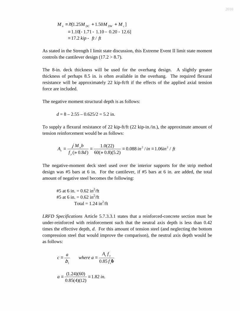
]50.125.1[ cDWDCn MMMM ++= h ]6.1220.010.171.1[10.1 ----= ftftkip /2.17 -=
As stated in the Strength I limit state discussion, this Extreme Event II limit state moment controls the cantilever design (17.2 > 8.7).
The 8-in. deck thickness will be used for the overhang design. A slightly greater thickness of perhaps 8.5 in. is often available in the overhang. The required flexural resistance will be approximately 22 kip-ft/ft if the effects of the applied axial tension force are included.
The negative moment structural depth is as follows: d = 8 – 2.55 – 0.625/2 = 5.2 in.
To supply a flexural resistance of 22 kip-ft/ft (22 kip-in./in.), the approximate amount of tension reinforcement would be as follows:
ftininindf
bMA
y
ns /06.1/088.0
)2.5)(8.0(60)22(0.1
)8.0(22 ==
»=
»=
j
The negative-moment deck steel used over the interior supports for the strip method design was #5 bars at 6 in. For the cantilever, if #5 bars at 6 in. are added, the total amount of negative steel becomes the following:
#5 at 6 in. = 0.62 in2
#5 at 6 in. = 0.62 in/ft
2
Total = 1.24 in/ft
2
/ft
LRFD Specifications Article 5.7.3.3.1 states that a reinforced-concrete section must be under-reinforced with reinforcement such that the neutral axis depth is less than 0.42 times the effective depth, d. For this amount of tension steel (and neglecting the bottom compression steel that would improve the comparison), the neutral axis depth would be as follows:
bf
fAawhereac
c
ys
¢==
85.01b
.82.1)12)(4(85.0)60)(24.1( ina ==
2010

.55.185.082.1 inc ==
3.02.5
55.1==
dc
Because c/d is slightly less than 0.42, the section is under-reinforced, even without the beneficial effect of the compression steel.
The actual flexural resistance is then the following:
./.6.26)12(
282.12.5)60)(24.1)(0.1(
2ininkipad
bfA
M ysu -=
÷øö
çèæ -
=÷øö
çèæ -=
j
The flexural resistance is reduced because of the axial tensile force in the deck of 3.7 kip/ft. A portion of a typical interaction diagram for a reinforced-concrete member is shown in Figure 61-5E. If it is conservatively assumed that the interaction diagram is linear between pure flexure and pure tension, the following relationship holds.
0.1=+n
u
n
u
MM
PP
Solving for Mn
:
÷÷ø
öççè
æ-=
n
unu P
PMM 0.1
wherein Pu = T = 3.87 kip/ft, and Pn = Astfy. Ast is the total top and bottom steel (computed as 0.41 in.2
/ft for the strip method of design for the deck) area.
Ast = 1.24 + 0.41 = 1.65 in.2
P/ft
n
= (1.65)(60) = 99 kip/ft
ftftkipM u /6.2599
7.30.16.26 -=÷øö
çèæ -=
The capacity of 25.6 kip-ft/ft is greater than the demand of 17.2 kip-ft/ft, meaning that the suggested negative-moment steel arrangement is adequate.
Directly below the railing, the negative-moment reinforcement must resist the collision moment of 12.6 kip-ft/ft. The calculated reinforcement will be satisfactory if it is fully developed at this point. The basic tension development length is taken from LRFD Specifications Article 5.11.2.1.1, as follows:
2010
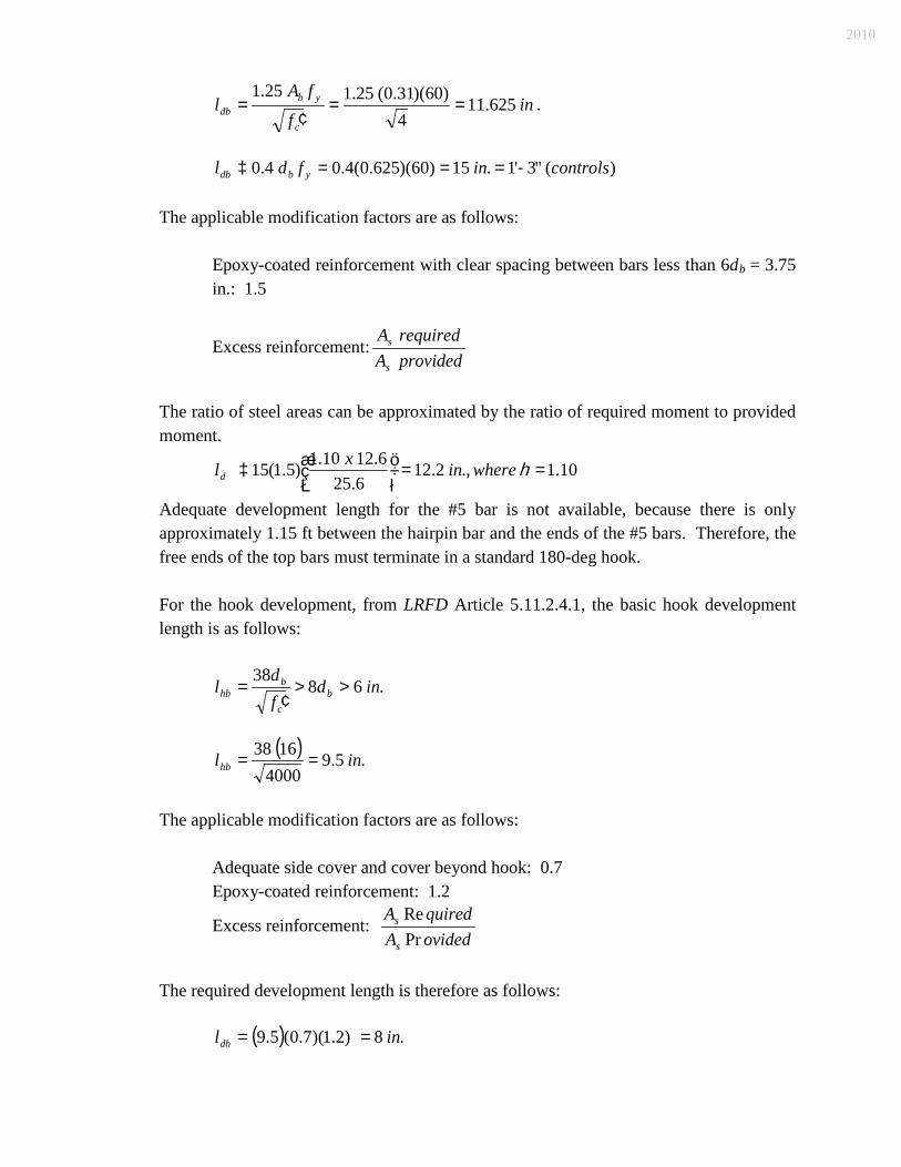
inf
fAl
c
ybdb 625.11
4)60)(31.0(25.125.1
==¢
= .
)("3'1.15)60)(625.0(4.04.0 controlsinfdl ybdb -===³ The applicable modification factors are as follows:
Epoxy-coated reinforcement with clear spacing between bars less than 6db
= 3.75 in.: 1.5
Excess reinforcement:providedArequiredA
s
s
The ratio of steel areas can be approximated by the ratio of required moment to provided
moment.
1.10 .,2.126.25
6.1210.1)5.1(15 ==÷øö
çèæ³ hwhereinxld
Adequate development length for the #5 bar is not available, because there is only approximately 1.15 ft between the hairpin bar and the ends of the #5 bars. Therefore, the free ends of the top bars must terminate in a standard 180-deg hook.
For the hook development, from LRFD Article 5.11.2.4.1, the basic hook development length is as follows:
.6838
indfd
l bc
bhb >>
¢=
( ) .5.94000
1638 inlhb ==
The applicable modification factors are as follows: Adequate side cover and cover beyond hook: 0.7 Epoxy-coated reinforcement: 1.2
Excess reinforcement: ovidedAquiredA
s
s
PrRe
The required development length is therefore as follows: ( ) .8)2.1)(7.0(5.9 inldh ==
2010

8 in. is greater than 8(0.625), or 5 in., and is greater than 6 in.
Adequate development length for the hook is available, because there is approximately 14 in. between the hairpin dowel and the hook extremity.
9. Cutoff Point for Additional Deck Overhang Bars
. The additional #5 bars placed in the top of the deck must extend beyond the centerline of the exterior beam far enough to satisfy flexural and development requirements. The theoretical cutoff point is where the continuing bars provide flexural resistance equal to the dead-load moment plus the collision moment, with a j factor of 1.0.
The flexural resistance for the continuing bars (No. 5 at 6 in. = 0.62 in2
/ft) is as follows:
ina 91.0)12)(4(85.0)60)(62.0(
==
ftftkipM n /7.14291.02.5
12)60)(62.0(0.1
-=÷øö
çèæ -=j
A simplified and conservative approach to locating the cutoff point is to consider the railing weight, slab overhang dead load, and collision moment as causing a negative moment at the exterior support. Using a carry-over factor of ½, the moment at the interior support is determined. The future wearing surface and the deck dead load in the first interior span are neglected, because they will reduce the cutoff distance. Accordingly, the moment at the centerline of the exterior support for the Extreme Event II limit state is as follows:
Railing: 1.25(0.383)(4.125 ft) = -1.97 kip-ft/ft Deck: 1.25(0.1)(4.75 ft)2
FWS: 1.50(0.035)(3.29 ft)/2 = -1.41 kip-ft/ft
2
Collision: = /2 = -0.28 kip-ft/ft
-12.6 M
kip-ft/ft ext
= -16.3 kip-ft/ft
Including the load modifier, Mext
= -(1.10)(-16.3) = -17.9 kip-ft/ft. The moment at the centerline of the first interior support is then -½(-17.9) = +9.0 kip-ft/ft. Figure 61-5F shows the resulting moment diagram. The theoretical cutoff point is determined by simple proportion at 1.19 ft from the centerline of the exterior support. The bars must extend beyond the theoretical point (LRFD Article 5.11.1.2.1) by the largest of the following:
Structural depth, d, of the member = 5 in.; 15 bar diameters: 15(0.625) = 9.375 in. (Controls); or
2010

1/20 of the clear span: (120 – 20)/20 = 5 in
The bars should extend 14.3 in. + 9.375 in. = 23.675 in., or 1.97 ft from the centerline of support. Development length is adequate by inspection. Figure 61-5G shows the details of the additional bars in the overhang.
61-5.03 Transverse Edge Beam
61-5.03(01) Design of Transverse Edge Beam LRFD Specifications Article 9.7.1.4 requires the end zone of the deck to have adequate resistance against the increase of force effects due to the structural discontinuity at the deck joint. This additional resistance is easily provided by the diaphragms that are commonly used for an integral end bent superstructure. In the absence of diaphragms, a transverse edge beam, hidden or exposed, is acceptable. The beam should be designed as specified in LRFD Specifications Article 4.6.2.1.4. Typical configurations of transverse edge beams are shown in Figures 61-5H through 61-5L for various types of superstructures. For the positive-moment steel, the designer should consider using crankshaft bars (see Figure 61-5L) instead of straight bars between beams, unless the requirements for tension development length provided in LRFD Specifications Article 5.11.2.1 can be satisfied by placement of straight bars between beams. Crankshaft bars that extend from coping to coping can be difficult to handle and install. Preferably, they should consist of two bars that are lapped above the beam at the centerline of the roadway or above a beam that is adjacent to the centerline of roadway. As shown in Figure 61-5L, past designs have included a 45-deg fillet along the inside face of the edge beam. The 45-deg fillet is available as an option for additional resistance to force effects or assurance of a smooth flow of stress at a location where there is a significant change in section depth. For a deck with no skew or with a skew angle not exceeding 25 deg, the transverse deck reinforcement will be placed parallel to the skew, but for a greater skew angle, it must be placed perpendicular to the supporting beams. For a greater skew angle, the transverse deck reinforcement will be terminated at points encompassed by the edge beam. Hence, it should not be counted as part of the resistance. For a skew angle not exceeding 25 deg, the top transverse deck steel may be included in the design of the edge beam. For a skew angle exceeding 25 deg, the negative moment reinforcement in the edge beam should be placed below the top longitudinal deck steel. Although LRFD Article 4.6.2.1.4c specifies a strip width for positive and negative moment for the edge member, it is acceptable to use the thickened edge beam or diaphragm width. The edge beam will be assumed to carry one truck axle for each vehicle considered.
2010

61-5.03(02) Transverse-Edge-Beam Design Example A transverse edge beam is to be designed for the beam-slab bridge shown in Figure 61-2B. Assume a skew angle of zero and the dimensions shown in Figure 61-5 I. Flexural and shear design are based on the Strength I limit state, as follows:
ksif
ksif
y
c
604
==¢
90.0=j For this example, the edge beam dead-load moments are based on the area of the rectangular section. The minimum width of 2 ft will be used, and the section depth will be taken as 1’-10”. This depth places the bottom of the edge beam flush with the bottom of the fillet for the AASHTO type IV I-beam as follows: Area of Section: (24)(22) = 528 in
Dead Load
2 ( )( ) ftkipftlb /55.0/550
144150528
===
The edge beam is assumed to carry one axle from each truck. The live load moments are as computed previously in Section 61-2.02(02) and Section 61-2.02(03). The concrete railing and future wearing surface moments will be based on the beam width, as follows: Railing: (0.383 kip/ft) (2 ft) = 0.77 kip Future Wearing Surface: (0.035) (2 ft) = 0.07 kip/ft The maximum factored moments for the edge beam are shown in Figure 61-5M. The negative-moment steel area required is computed using Equation 61-2.3, with the web thickness taken as 2 ft. If the edge beam’s negative steel will be placed above the deck’s longitudinal steel and the deck’s transverse steel is included in the resistance, the structural depth of the edge beam (subtracting sacrificial wearing surface, additional cover, and bar radius for #6 bar) is as follows: .1.192/75.00.25.022 ind s =---= The required steel area from Equation 61-2.3 is then 0.87 in2. Because the existing negative-moment slab steel provides an area of 0.62 in2
/ft [see summary of steel at end of Section 61-2.02(06)], its contribution to the total beam steel is as follows:
2010

2 (0.62) = 1.24 in
2
The contribution of the existing slab steel satisfies the required area, therefore no additional steel is required. The section will be under-reinforced according to LRFD Equation 5.7.3.3.1-1, if the following is true.
42.0£ed
c
where c is the depth to the neutral axis and de
is the structural depth.
Using the equivalent slab steel area, the stress-block depth is as follows:
bf
fAa
c
ys
¢=
85.0
ina 91.0)24)(4(85.0
)60)(24.1(== .
The neutral-axis depth is as follows:
.07.185.091.0
1
inac ===b
and
42.006.01.19
07.1<==
edc
so the section is therefore under-reinforced. The positive-moment steel area required is computed in a similar manner. The structural depth for positive moment is as follows: ds
= 22 – 0.5 – 1.0 – 0.5 – 0.625/2 = 19.7 in.
(Computed with 0.5-in. sacrificial wearing surface, 1-in. cover, #4 tie bar, and #5 bar.) Equation 61-2.3 yields As = 0.90 in2. Using three #5 bars in the bottom of the edge beam provides 0.93 in2
.
The resulting positive moment section is under-reinforced by inspection.
2010

According to LRFD Article 5.8.3.2, the critical section for shear is at a distance dv from the face of the support, where dv is the structural depth of the member. The highest shear will occur in the exterior span, near the interior support. For this design example, dv
= 17.5 in. Adding half of the beam flange locates the critical section at 17.5 + ½(20) = 27.5 in. from the center of support, which is at the 0.77L point in the span.
Figure 61-5N shows the dashed influence line for reaction at the first support and the influence line for the shear at the critical section. Areas of the influence line for reaction at support 1 are as follows: Out-to-out copings for edge beam dead load: 120.9 in. = 10.07 ft Between faces of railings for FWS: 94.5 in. = 7.88 ft The dead-load shear at the critical section due to the edge beam weight (0.55 kip/ft) is computed by summing the upward reaction at the first support and the downward beam load to the left of the critical section (57 in. + 92.5 in. = 149.5 in. = 12.46 ft). Edge Beam V: 0.55 kip/ft (120.9 – 149.5 in.) = -1.31 kip Factored: -1.31 (1.25) = -1.64 kip The calculation is made similarly for the future wearing surface, except that the length of load to be subtracted is as follows: 39.5 in. + 92.5 in. = 132 in. = 11 ft FWS V: 0.07 kip/ft (94.5 – 132 in.) = -0.22 kip Factored: -0.22 (1.5) = -0.33 kip The railing shear is computed with the shear influence ordinates at the centroid of the railing, as follows: Railing V: 0.75 kip (0.529 – 0.023) = 0.38 kip Factored: 0.38 (0.9) = 0.34 kip The total factored dead-load shear at the critical section is -1.47 kip. For live load, a single truck axle will be placed in the first span, with one wheel at the critical section and the other at 6 ft away. Using the appropriate influence ordinates yields the following: Live-Load V: 16 kip (-0.852 – 0.210) = -16.99 kip
2010

Applying the multiple presence factor (1.2), the dynamic load allowance (1.33), and the load factor (1.75) provides the following: Factored: -16.99 (1.2) (1.33) (1.75) = -47.5 kip The dead-load shear is a small (3%) contributor to the total. The sign of the shear follows the normal convention, but is otherwise unimportant. The equations for shear design from the LRFD Specifications for a reinforced-concrete member are as follows: scn VVV += (5.8.3.3-1) vvcc dbfV ¢= b0316.0 (5.8.3.3-3) (b = 2.0 for reinforced concrete)
s
dfAV vyv
s
aaq sin)cot(cot += (5.8.3.3-4) (q = 45° for reinforced concrete)
(a = 90° for vertical stirrups) which reduces to the following:
s
dfAV vyv
s =
The nominal shear resistance, Vn
, is multiplied by the resistance factor j to arrive at the factored shear resistance. For obtaining the stirrup spacing, s, the equations can be rearranged as follows:
s
vyvc
us V
dfAsandVVV =-=
j
Where Vu is the total factored shear, dead load plus live load (1.5 + 47.5 = 49.0 kip). The resistance factor for shear is 0.9 (LRFD Article 5.5.4.2.1). In the above equations, dv
is the distance between the resultant tension and resultant compression forces in the member as follows:
ys
nv fA
Md = LRFD Equation C5.8.2.9-1
Substituting the total factored moment at Point B for Mn
and the supplied steel area yields the following:
2010

.6.16)60()93.0(
)/.12)(26.77(2 in
inftinftkipdv =
-=
The value for dv need not be less than the larger of 0.9de
or 0.72h.
For this member, h = 22 in. – 0.5 in. = 21.5 in., and de = 19.5 in. The minimum value of dv is therefore the larger of (0.9)(19.5) = 17.6 and 0.72(21.5) = 15.5. Therefore, dv is at least 17.6 in., which is larger than the equation value of 16.6 in. Use dv
= 17.6 in.
Substituting the appropriate quantities yields the following: kipVc 4.53)6.17()24(4)0.2(0316.0 ==
kipVs 04.14.539.00.49
=-=
If Vs
is negative, nominal shear should be used.
Using #4 stirrups, with two legs effective for shear, Av = 2(0.2) = 0.4 in2
. The required stirrup spacing is therefore the following:
ftins 83.33.40604.1
)6.17)(60)(4.0(===
The maximum stirrup spacing (since the shear stress is obviously low, less than 0.125 cf ¢ ) is 0.8dv
= 0.8(17.6) = 14.1 in.
Placing #4 stirrups at a nominal spacing of 1’-0” (Figure 61-5 I) throughout the member will satisfy the shear requirements.
61-5.04 Design of Bridge Railing
Section 61-6.0 discusses the types of bridge railings that may be used. Section 61-5.04 discusses the structural evaluation of concrete or steel railings at the copings of a bridge. A concrete barrier railing is built monolithically and continuous with no contraction joints at either mid-span or over the interior supports. Full-depth open joints will be provided only between the end of the structure and the reinforced-concrete bridge approach and at expansion joints on a structure composed of two or more units.
2010
The INDOT Standard Drawings illustrate concrete railings with the preferred arrangement of reinforcement. This arrangement of railing steel is a departure from traditional design in which the railing has essentially been considered as a vertical flexural element and the longitudinal steel, as secondary, being compatible with frequent relief joints. The uninterrupted railing becomes a primary longitudinal flexural element, playing a significant role in resisting both gravitational and impact loading. The longitudinal steel is appropriate for this role, in addition to controlling shrinkage-caused cracking. Stirrups connecting any continuously-placed (whether or not structurally continuous) concrete railing, curb, parapet, sidewalk, or median to the concrete deck should be determined assuming full composite action at the interface, in accordance with LRFD Specifications Article 5.8.4. 61-6.0 BRIDGE RAILING
61-6.01 Test Level Selection
The basic parameter for bridge-railing selection is the Test Level required at the site. This is a function of the following: 1. highway design speed; 2. average annual daily traffic and percent trucks; 3. bridge-railing offset; 4. highway geometry (grades and horizontal curvature); 5. height of deck; and 6. type of land use below deck. The detailed methodology for determining a bridge railing’s Test Level is described herein. The methodology has been adapted from the AASHTO publication Guide Specifications for Bridge Railings. The performance-level designations in the Guide Specifications have been converted to the Test Level designations in National Cooperative Highway Research Program Report 350 (NCHRP 350) Recommended Procedures for the Safety Performance Evaluation of Highway Features. The Guide Specifications methodology is based on a benefit/cost analysis which considers occupant safety, vehicular types, highway conditions and costs. The overall objective is to match the bridge railing’s Test Level (and therefore costs) to site needs. The Performance Level (PL-__) terminology applies to the AASHTO Guide Specifications for Bridge Railings. Under the new NCHRP 350 criteria, performance of each bridge railing and associated transition is measured in terms of Test Levels (TL-__). A bridge-railing equivalency table for converting PL-1, PL-2 and PL-3 railings to TL-2, TL-4 and TL-5 railings is provided in Figure 61-6A, Bridge Railing Level Equivalency.
2010

NCHRP 350 identifies six Test Levels. To limit the number of necessary bridge railings, three of these Test Levels have been selected, and warrants have been developed for their use. The Test Level is selected based on the following. 61-6.01(01) TL-2 A TL-2 bridge railing is appropriate on a bridge which meets the following: 1. the bridge is located on a route not on the State highway system, and the adjusted AADT
in the construction year appears within the TL-2 range shown in Figure 49-6D(30), 49-6D(40), 49-6D(45), 49-6D(50), or 49-6D(55), Median Barrier and Bridge Railing Test Level Selection, for the appropriate design speed; or
2. the bridge is located on a State-highway-system route with a design speed of 45 mph or
lower and the adjusted AADT in the construction year appears within the TL-2 range shown in Figure 49-6D(30), 49-6D(40), or 49-6D(45), for the appropriate design speed.
61-6.01(02) TL-4 A TL-4 bridge railing is appropriate on each bridge which meets the following: 1. the criteria for TL-2 are not met; and 2. the adjusted AADT in the construction year appears within the TL-4 range shown in
Figure 49-6D(30), 49-6D(40), 49-6D(45), 49-6D(50), 49-6D(55), 49-6D(60), or 49-6D(65), for the appropriate design speed.
61-6.01(03) TL-5 A TL-5 bridge railing is appropriate on a bridge where the adjusted AADT in the construction year appears within the TL-5 range shown in Figures 49-6D(30) through 49-6D(65), whichever applies. 61-6.01(04) TL-6
2010

A TL-6 bridge railing is intended to reduce to almost zero the probability that a large van-type, semi-trailer truck will penetrate the railing. The TL-6 bridge railing is intended to contain and redirect a tanker trailer truck, which has a very high point of contact with a bridge railing. The decision to use a TL-6 bridge railing is a policy decision based on a site-by-site evaluation; therefore no numerical thresholds are provided. As an example, a TL-6 bridge railing may be selected on a highway with an extremely high volume of large trucks (or tanker trucks) where rollover or penetration beyond the barrier would result in severe consequences. 61-6.01(05) Making Test Level Determination Test Level determination applies directly to a level roadway on tangent, with a bridge deck surface approximately 35 ft above the under-structure ground or water surface, and with low-occupancy land use or shallow water under the structure. The traffic volume used to determine the Test Level is the construction-year AADT. For highway conditions that differ from those described above, the AADT should be adjusted by the correction factors shown in Figure 49-6B, Grade Traffic Adjustment Factor, Kg, and Curvature Traffic Adjustment Factor, Kc; and Figure 49-6C, Traffic Adjustment Factor,Ks
, for Deck Height and Under-Structure Shoulder Height Conditions. The high-occupancy land use referred to in Figure 49-6C applies to a site where there is a relatively high probability for injury or for loss of human life. The low-occupancy land use applies to a site where the probability for injury or loss of human life is relatively low.
Once the adjusted AADT is determined, the appropriate Test Level can be determined from Figure 49-6D(30), 49-6D(40), 49-6D(45), 49-6D(50), 49-6D(55), 49-6D(60), or 49-6D(65), Median Barrier and Bridge Railing Test Level Selection, for the design speed shown in the figure designation. The following procedure will apply to the determination of the appropriate Test Level. 1. Determine adjustment factors Kg and Kc from Figure 49-6B, and Ks
from Figure 49-6C.
2. Calculate the adjusted AADT by multiplying the construction-year AADT (total for both directions) by the three adjustment factors, as shown below.
Adjusted AADT = (Construction-year AADT) (Kg) (Kc) (Ks
).
3. Determine the figure in the 49-6D figures series which is appropriate for the design speed. If the design speed is 35 mph, a straight-line interpolation between Figures 49-6D(30) and 49-6D(40) should be used to determine the adjusted AADT range.
2010

4. Locate the appropriate line in such figure under the Site Characteristics column. 5. Move across to the columns corresponding to the appropriate Highway Type. 6. Determine which of the three columns (TL-2, TL-4, or TL-5) includes the adjusted AADT
value calculated in Step 2 to identify the appropriate Test Level. Each side of a bridge should be checked against these criteria. This is especially important for a bridge on a horizontal curve. The higher Test Level warrant should be used for both sides of a structure. See Section 49-6.03 for example calculations on the selection of a TL-4 or TL-5 bridge railing. For a minor bridge rehabilitation project which does not include bridge-deck replacement or deck widening and the bridge currently has a crashworthy TL-4 bridge railing, the existing railing need not be upgraded to a TL-5 railing, though the warrants for the TL-5 railing are satisfied. If there is no significant history of truck accidents, the installation of the TL-5 bridge railing should be deferred until the time of deck replacement or deck widening. However, if truck accidents are a problem, consideration should be given to installing the TL-5 railing on the rehabilitation project along with countermeasures to reduce the truck-accident problem.
61-6.02 Bridge-Railing-Type Selection
61-6.02(01) INDOT Standard Railings Once the Test Level has been determined, a bridge railing type should be selected to match the required Test Level and other considerations (e.g., aesthetics, owner preference). Figure 61-6B, Bridge Railing Types, summarizes the Department-standardized bridge-railing types for each Test Level. Figure 61-6C summarizes the Department standardized bridge-railing pay items. 61-6.02(02) FHWA-Approved Non-INDOT-Standard Railings There are other bridge railings which have passed NCHRP 350 crash tests for specified Test Levels, in addition to those which the Department has standardized. These are identified on the FHWA’s website, http://safety.fhwa.dot.gov/roadway_dept/road_hardware/bridgerailings.htm. If one of these devices is desired to be used for a specific project, the required documentation to be downloaded from the website and provided is as follows:
2010

1. an acceptance letter from the FHWA that approves the device for use; and 2. complete details for the device as successfully crash tested. The device may be modified for specific-project use. However, the shape, strength, and performance requirements cannot be changed. If the device is to be modified, the additional required documentation to be provided is as follows: 1. complete details showing the modifications; and 2. calculations showing that the modified version still meets the strength and performance
requirements of the crash-tested version. The appropriate transition or end treatment must be determined. This may be done by further investigating the bridge-railing details. Such details should be provided, along with documentation that the transition or end treatment is appropriate for the bridge railing. If an appropriate transition or end treatment cannot be found, the bridge railing cannot be used. 61-6.02(03) Considerations if Sidewalk Present Including a sidewalk on a bridge may impact the selection or location of the bridge railing. The potential problem is that, once a vehicle strikes a curb, it may become airborne. Depending upon the lateral offset of the bridge railing, the vehicle may impact the railing while airborne and thus, may interfere with the proper vehicle/bridge railing interaction. The following will apply to the selection and location of a bridge railing in combination with a sidewalk. 1. Design Speed of 45 mph or Lower
. Only a railing shown to be crashworthy in the presence of a sidewalk may be used. The bridge railing type may be selected based on the Test Level required at the site as described above, or a vertical concrete wall of the appropriate height may be provided at the back of the sidewalk. The Test Level of such wall should match that of a concrete shape F bridge railing.
2. Design Speed of 50 mph or Higher. The bridge railing cannot be placed at the coping side of the sidewalk, therefore it must be placed between the roadway and the sidewalk. A pedestrian- or bicycle railing should then be placed at the coping side of the sidewalk as described below. The height of the vehicular bridge railing between the roadway and the sidewalk must meet or exceed the minimum height requirement of a pedestrian railing, 42 in., or a bicycle railing, 54 in., whichever applies. Where the vehicular bridge
2010

railing is placed between the roadway and the sidewalk, the sidewalk need not be raised; i.e., the roadway surface and sidewalk surface may be at the same elevation. However, the sidewalk drainage pattern should be reviewed. The guardrail transition and bridge-railing transition should be connected to the pedestrian railing. An impact attenuator type R1 should be connected to the bridge railing.
61-6.03 Bridge-Railing-Design Details
61-6.03(01) Superelevated Bridge Deck The INDOT Standard Drawings illustrate the orientation of concrete shape F bridge railing with the bridge deck surface for a bridge on a superelevated roadway section. 61-6.03(02) Barrier Delineators Barrier delineators are to be placed on each bridge railing. However, barrier delineators are not to be placed on a bridge railing at the coping side of a sidewalk. The location of the delineators along the bridge railing should be as described in the INDOT Standard Specifications. Barrier delineators should be placed on the each roadway face of a bridge railing transition.
61-6.04 Bridge-Railing Transition
Steel-element roadside barriers deflect upon impact, but rigid bridge railings normally will not. Therefore, where a steel-element roadside barrier approaches a rigid bridge railing, a transition is necessary to gradually strengthen the steel-element roadside barrier as it approaches and connects to the bridge railing. The following will apply to these transitions. 61-6.04(01) Type The preferred transition for each bridge railing type is shown in Figure 61-6B. Most systems include both a guardrail transition and a bridge-railing transition. The details are shown in the INDOT Standard Drawings identified in Figure 61-6B. A transition is typically used at each location, except where an intersecting road or driveway prevents the placement of a proper design. To use the bridge-railing transition listed, there must be space to place at least 25 ft of roadside barrier between a curved W-beam guardrail connector terminal system or curved W-beam guardrail system and the beginning of a guardrail transition type TGB.
2010

Bridge railing transition type WBC is not identified in Figure 61-6B. It may be used with concrete bridge railing shape F, common height, only where the proximity of an intersecting road or driveway prevents the proper installation of the preferred transition. Where at least one bridge-railing transition type WBC is required, such transition should be used for all bridge railing ends. 61-6.04(02) Location The following will apply to the location of a bridge-railing transition. 1. Reinforced-Concrete Bridge Approach (RCBA)
. The ideal treatment is to locate a bridge-railing transition along the RCBA. This will keep the deck drainage not collected in the deck drains from flowing down the spill slopes at the bridge corners, which may cause erosion at the end bents. Placing the transition on the RCBA will require moving the connection between the bridge-railing transition and the guardrail transition a sufficient distance from the wing to allow placement of the posts required with the transition.
2. Bridge Corner
. A transition should be used at each bridge corner for each bridge-railing type, including the trailing end of a bridge railing on a one-way roadway, such as a ramp or one roadway of a divided highway.
3. Bridge Deck
. If it is necessary to locate the transition on the bridge deck, the wings must be extended laterally a sufficient distance to provide a minimum clearance of 6 in. between the roadside face of the wing and the backs of the guardrail transition posts.
4. Intersecting Road or Drive
. The presence of an intersecting road or drive close to the bridge may complicate the location of the transition. Where practical, the intersecting road or drive should be relocated to allow placement of the bridge-railing transition on the RCBA. Where this is not practical, the consideration of the bridge-railing transition should be determined in the order of preference as follows:
a. it should be placed on the bridge deck if the structure has integral or semi-integral end bents;
b. a modified version of the bridge-railing transition that can be used with guardrail
transition type WGB should be placed on the RCBA;
2010

c. a modified version of the bridge-railing transition that can be used with guardrail transition type WGB should be placed on the bridge deck if the structure has integral end bents;
d. an impact attenuator should be used at the end of the bridge railing; or
e. since standard details for modified versions of bridge-railing transitions that can
be used with the guardrail transition type WGB are not available, details of a modified version of the appropriate concrete-bridge-railing transition should be included in the plans if an intersecting drive or public road approach cannot be relocated away from the end of the structure.
5. Expansion Joint
. The bridge-railing transition cannot be located on the bridge deck if a deck expansion joint is located between the bridge deck and the mudwall.
6. Alternative Location
. In a situation with severe space restrictions, transition location or design modifications which do not comply with the above criteria may be necessary. Such an alternative treatment requires approval by the Production Management Division’s Structural Services Office manager.
61-6.05 Pedestrian Railing
If a sidewalk is to be placed on a bridge, and the design speed is 50 mph or higher, a bridge railing should be used to separate vehicular traffic from pedestrians, and a pedestrian railing should be placed on the outside edge of the sidewalk. If the design speed is 45 mph or lower, the need for protection of pedestrians by means of a combination vehicular bridge railing/pedestrian railing will be considered on a site-by-site basis. Additional considerations to be made are as follows: 1. design speed; 2. vehicular-traffic volume; 2. pedestrian-traffic volume; 4. accident history; 5. geometric impacts (e.g., sight distance); 6. practicality of providing proper end treatments; 7. construction costs; and 8. local preference. Figure 61-6D shows the typical reinforcing-steel requirements for a bridge sidewalk.
2010

61-6.06 Bicycle Railing
If bicyclists are permitted to use a bridge, a bicycle railing may be warranted. The following will apply. 61-6.06(01) Bicycle Path This is defined as a bikeway physically separated from motorized vehicular traffic by an open space or barrier and either within the highway right-of-way or within an independent right-of-way. Each bridge which is a part of a bicycle path will require pedestian railing of 42-in. height. 61-6.06(02) Other Facility The need for combination vehicular bridge railing/bicycle railing to protect bicyclists will be considered on a site-by-site basis. Additional considerations to be made are as follows: 1. motor-vehicular traffic design speed; 2. motor-vehicular traffic volume; 3. bicycle traffic volume; 4. accident history; 5. geometric impacts (e.g., sight distance); 6. practicality of providing proper end treatments; 7. construction costs; and 8. local preference. 61-7.0 BRIDGE APPURTENANCES
61-7.01 Outside Curbs
Except for the base of two-tubed curb-mounted bridge railing, outside curbs are only used on a bridge in conjunction with a sidewalk. The typical curb height is 8 in. where used in conjunction with a sidewalk, unless a vehicular bridge railing is placed between the roadway and the sidewalk. For this situation, the roadway and sidewalk will be at the same elevation.
61-7.02 Center Curb or Median Barrier
2010

A center curb or a median barrier on a structure should be a continuation of the curb or median barrier on the approaching roadway. The use of a roughened construction joint between the bridge deck and the center curb or median barrier should be provided. Curb or median barrier should be anchored to the bridge deck with #5 bars spaced at 12 in. maximum.
61-7.03 Lighting
The Highway Management Division’s Office of Traffic is responsible for determining warrants for highway lighting. The district traffic office may offer input regarding lighting requirements for an INDOT project in an urban area. Warrants for, and the design of, lighting for a local public agency project shall be determined by the designer and the LPA. Section 78-2.0 discusses warrants for lighting on a bridge structure. Where lighting will be provided on an INDOT bridge, the Traffic Review Team will determine the pole size and spacing and submit this information to the project manager. The INDOT Standard Drawings provide the details for attaching standard luminaire supports to a concrete bridge railing.
61-7.04 Traffic Signals
Traffic signals may currently or be proposed to be located near a bridge. It may be appropriate to provide conduits across the bridge for the electrical service. The following will apply. 7. Bridge Location
. For each bridge located within an urbanized area, or within 2 mi of its boundary, the designer should contact the Office of Traffic. This Office will determine the need for conduits across the bridge.
2. Junction Boxes
. Where conduits will be provided, junction boxes should be located at approximately 250-ft intervals. The Office of Traffic will provide design details for the junction boxes for incorporation into the plans.
61-7.05 Utilities Located on an INDOT Bridge
The Production Management Division’s Utilities Team and the designer will work together to determine the proper accommodation of utilities across a highway structure. Chapter Ten describes the policy regarding the attachment of utility lines to a bridge. Chapter Ten also discusses procedures on permit applications and cost reimbursement. For approved utility attachments to a bridge, the following procedure applies. 1. Preparation. The utility company must prepare the attachment details for the utility.
These are submitted to the Utilities Team.
2010

1. Review and Approval
. The Utilities Team reviews the attachment details and submits these to the designer for comment. The Utilities Team will notify the utility company of any needed revisions. Once all changes have been made, the Utilities Team will approve the utility attachment details and process the Utility Agreement.
3. Plans Incorporation
. The Utilities Team will submit the approved utility attachment details to the designer for incorporation into the final contract plans.
2010
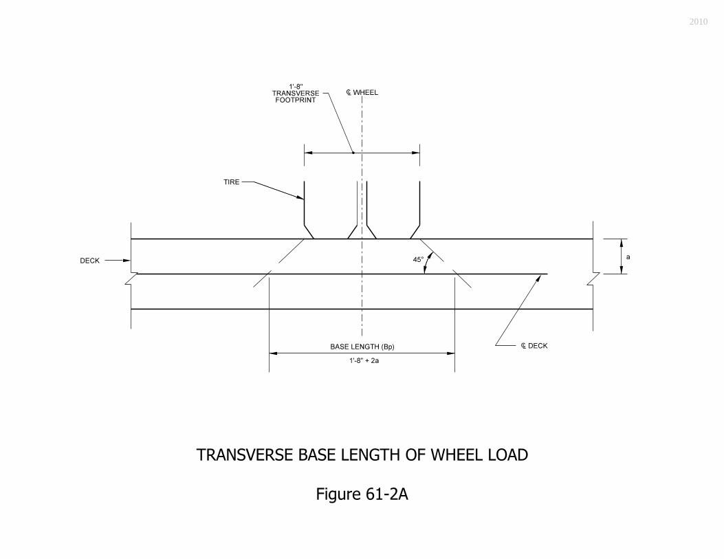
2010

2010

2010
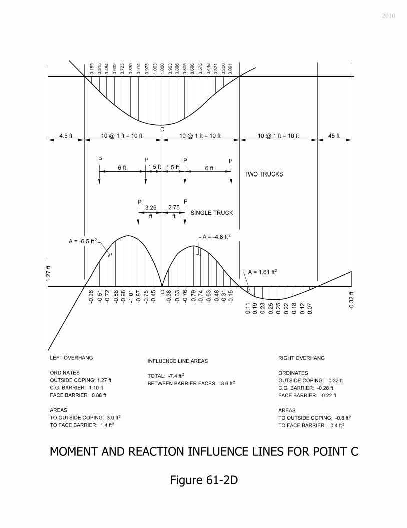
2010

2010

Point Load InfluenceOrdinate or Area
M (kip-ft)
Strip Width
(ft)
M (kip-ft per ft)
Multiple PresenceFactor
Dyn. Allow.
Load Factor
Factored Mu
(kip-ft/ft)Slab 0.115 kip/ft +1.9 ft2 +0.22 1 +0.22 n/a n/a 1.25 +0.28
FWS*0.035 kip/ft +5.0 ft2 +0.18 1 +0.18 n/a n/a 1.50 +0.27
Railing 0.383 kip -2.1 ft -0.82 1 -0.82 n/a n/a 0.90 -0.74 B
Wheel 16.0 kip +1.7 ft +27.50 7.7 +3.59 1.20 1.33 1.75 +10.03
Total +9.84
Slab 0.115 kip/ft -7.4 ft2 -0.85 1 -0.85 n/a n/a 1.25 -1.06
FWS*0.035 kip/ft -8.6 ft2 -0.30 1 -0.30 n/a n/a 1.50 -0.45
Railing 0.383 kip +0.8 ft +0.32 1 +0.32 n/a n/a 0.90 +0.29 C
Wheel 16.0 kip -1.8 ft -29.00 6.5 -4.46 1.00 1.33 1.75 -10.38
Total -11.60
* FWS is taken to front face of railing Note: The factored moments shown in the table are based upon the load modifiers ηD, ηR, and ηI = 1.0.
CALCULATION OF FACTORED MOMENTS
Figure 61-2F
2010

2010

2010

2010

2010

2010
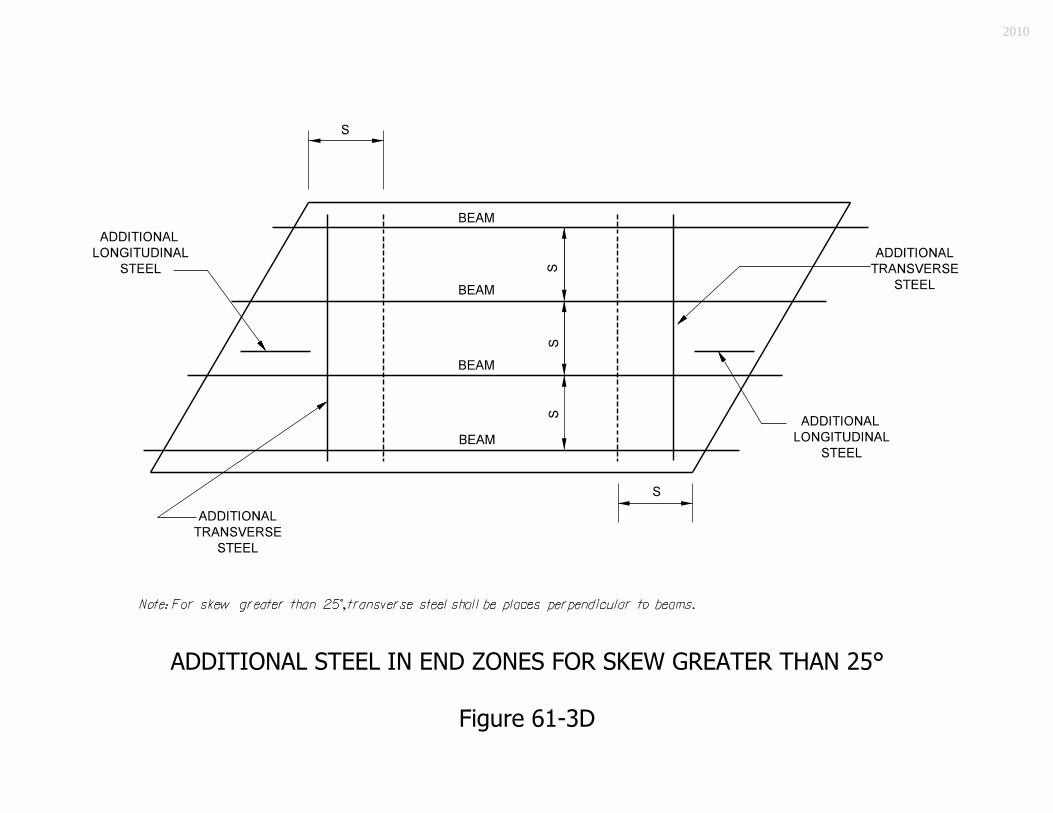
2010
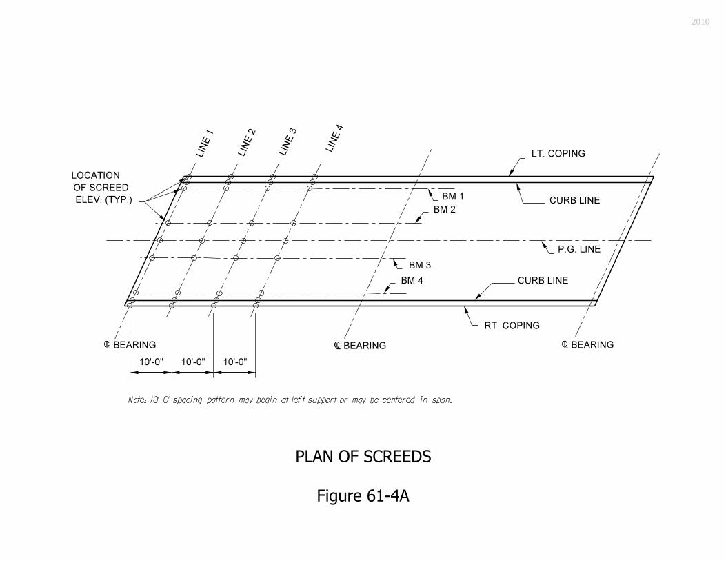
2010

2010

2010

2010
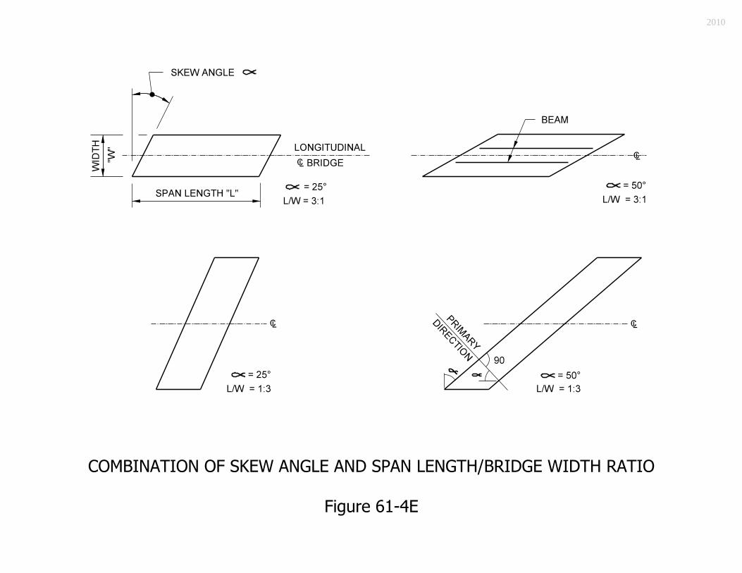
2010

2010

2010

2010
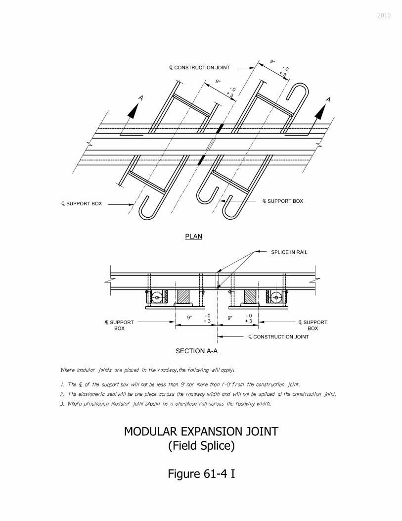
2010

2010

2010

Component Loading Moment Arm Factor Moment Railing 0.383 kip/ft 3.57 ft 1.25 1.71 kip-ft/ft
Deck (0.10)(4.19)
kip/ft 2.10 ft 1.25 1.10 kip-ft/ft
Overlay (0.035)(2.74)
kip/ft 1.37 ft 1.5 0.20 kip-ft/ft
Live Load 1.0 kip/ft 1.74 ft 1.75(1.33)(1.20) 4.86 kip-ft/ft Total 7.87 kip-ft/ft
CALCULATION OF FACTORED MOMENTS
Figure 61-5C
2010

2010

2010

2010

2010

2010

2010

2010

2010

2010
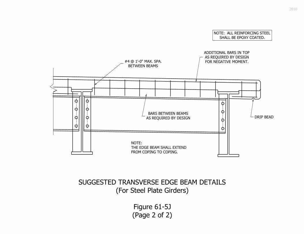
2010

2010

2010

2010
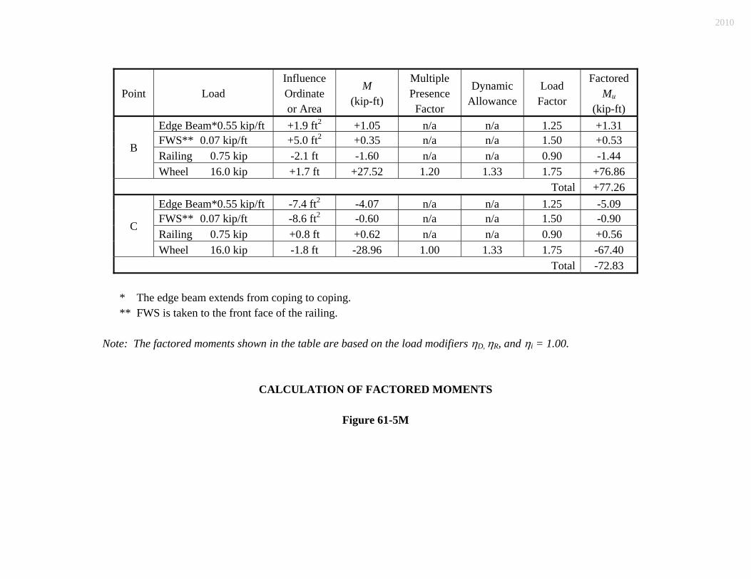
Point Load Influence Ordinate or Area
M (kip-ft)
Multiple Presence Factor
Dynamic Allowance
Load Factor
Factored Mu
(kip-ft) Edge Beam*0.55 kip/ft +1.9 ft2 +1.05 n/a n/a 1.25 +1.31FWS** 0.07 kip/ft +5.0 ft2 +0.35 n/a n/a 1.50 +0.53 Railing 0.75 kip -2.1 ft -1.60 n/a n/a 0.90 -1.44
B
Wheel 16.0 kip +1.7 ft +27.52 1.20 1.33 1.75 +76.86 Total +77.26
Edge Beam*0.55 kip/ft -7.4 ft2 -4.07 n/a n/a 1.25 -5.09FWS** 0.07 kip/ft -8.6 ft2 -0.60 n/a n/a 1.50 -0.90 Railing 0.75 kip +0.8 ft +0.62 n/a n/a 0.90 +0.56
C
Wheel 16.0 kip -1.8 ft -28.96 1.00 1.33 1.75 -67.40 Total -72.83
* The edge beam extends from coping to coping. ** FWS is taken to the front face of the railing. Note: The factored moments shown in the table are based on the load modifiers ηD, ηR, and ηi = 1.00.
CALCULATION OF FACTORED MOMENTS
Figure 61-5M
2010

2010

TESTING CRITERIA ACCEPTANCE EQUIVALENCIES
NCHRP Report 350 TL-1 TL-2 TL-3 TL-4 TL-5 TL-6 AASHTO Guide Specifications for Bridge Railings
--- PL-1 --- PL-2 PL-3 ---
BRIDGE-RAILING LEVEL EQUIVALENCY
Figure 61-6A
2010

Railing Designation TS-1 * PF-2 PS-2 TX **
Height Designation Common Pedestrian Pedestrian Pedestrian
Mounting Location
On bridge coping
Flush with bridge deck
Atop sidewalk of minimum 5
ft width
Either atop sdwk. of 5 ft
min. width, or flush with
bridge deck
Railing Element
Thrie-beam with steel
posts
2 steel tubes with steel posts on concrete parapet
2 steel tubes with steel posts
on concrete parapet
Concrete
Total Height 2’-9” 3’-6” 3’-6” 3’-6” Br. Rlg. Standard Drawings
n/a 706-BRPP-02, and -05, -06
706-BRPP-04 through -06
706-BRTX-01 through -04
Bridge Railing Transition none TPF-2 TPS-2 TTX
Br. Rlg. Trans. Standard Drawings
n/a 706-TTBP-03, -04, and -09
706-TTBP-07 through -09
706-TTTX-01 and -02
Guardrail Transition TGS-1 TGB TGB TGB
Gdrl. Trans. Standard Drawings
n/a 601-TTGB-01 through -05
601-TTGB-01 through -05
601-TTGB-01 through -05
* Bridge railing type TS-1 may be used only on a local-public-agency collector or local road.
Details for the bridge railing and transition are shown in INDOT Recurring Plan Detail 706-B-140d.
** Bridge railing type TX should be considered for an aesthetically-sensitive area.
BRIDGE-RAILING TYPES (Test Level 2)
Figure 61-6B
2010

Railing
Designation FC TR *** CF-1 PS-1 PF-1
Height Designation Common Common Common Pedestrian Truck
Mounting Location
Flush with bridge deck
On existing concrete parapet
Flush with bridge deck
Atop sidewalk of minimum 5 ft
width
Flush with bridge deck
Railing Element Concrete, shape F
Thrie beam with steel posts
2 steel tubes with steel posts
on concrete curb
1 steel tube with steel posts on
concrete parapet
1 steel tube with steel posts on
concrete parapet
Total Height 2’-9” 2’-10” 2’-11” 3’-6” 4’-2”
Br. Rlg. Standard Drawings
706-BCBR-01, -03, and -04
706-TBRC-01, -02, -03;
-TBRE-01; -TBRF-01, -02
706-BRTM-01 and -02
706-BRPP-03, and -05, -06
706-BRPP-01, and -05, -06
Bridge Railing Transition TBC none none TPS-1 TPF-1
Br. Rlg. Trans. Standard Drawings
706-CBRT-01 through -03 n/a n/a 706-TTBP-05
and -06 706-TTBP-01
and -02
Guardrail Transition TGB TGB TGT TGB TGB
Gdrl. Trans. Standard Drawings
601-TTGB-01 through -05
601-TTGB-01 through -05
601-TTGT-01 and -02
601-TTGB-01 through -05
601-TTGB-01 through -05
*** Bridge railing type TR should be used only to replace existing aluminum bridge railing
where no other modifications to a bridge are to be made, either as a spot improvement or within the limits of a 3R or 4R project.
BRIDGE-RAILING TYPES (Test Level 4)
Figure 61-6B (Cont’d.)
2010

Railing
Designation FT TF-2
Height Designation Truck Truck
Mounting Location
Flush with bridge deck
Flush with bridge deck
Railing Element Concrete, shape F
2 steel tubes with steel posts on
concrete parapet Total Height 3’-9” 4’-2”
Br. Rlg. Standard Drawings
706-BCBR-02, -03, and -04
706-BRTF-01 through -10
Bridge Railing Transition TBT PBT
Br. Rlg. Trans. Standard Drawings
706-CBRT-01, through -03
706-TPBT-01 through -09
Guardrail Transition TGB TGB
Gdrl. Trans. Standard Drawings
601-TTGB-01 through -05
601-TTGB-01 through -05
BRIDGE-RAILING TYPES (Test Level 5)
Figure 61-6B (Cont’d.)
2010
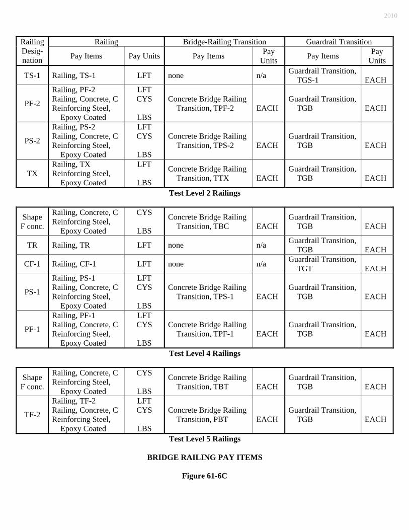
Railing Bridge-Railing Transition Guardrail Transition Railing Desig-nation Pay Items Pay Units Pay Items Pay
Units Pay Items Pay Units
TS-1 Railing, TS-1 LFT none n/a Guardrail Transition, TGS-1
EACH
PF-2
Railing, PF-2 Railing, Concrete, C Reinforcing Steel, Epoxy Coated
LFT CYS
LBS
Concrete Bridge Railing Transition, TPF-2
EACH
Guardrail Transition, TGB
EACH
PS-2
Railing, PS-2 Railing, Concrete, C Reinforcing Steel, Epoxy Coated
LFT CYS
LBS
Concrete Bridge Railing Transition, TPS-2
EACH
Guardrail Transition, TGB
EACH
TX Railing, TX Reinforcing Steel, Epoxy Coated
LFT
LBS
Concrete Bridge Railing Transition, TTX
EACH
Guardrail Transition, TGB
EACH
Test Level 2 Railings
Shape F conc.
Railing, Concrete, C Reinforcing Steel, Epoxy Coated
CYS
LBS
Concrete Bridge Railing Transition, TBC
EACH
Guardrail Transition, TGB
EACH
TR Railing, TR LFT none n/a Guardrail Transition, TGB
EACH
CF-1 Railing, CF-1 LFT none n/a Guardrail Transition, TGT
EACH
PS-1
Railing, PS-1 Railing, Concrete, C Reinforcing Steel, Epoxy Coated
LFT CYS
LBS
Concrete Bridge Railing Transition, TPS-1
EACH
Guardrail Transition, TGB
EACH
PF-1
Railing, PF-1 Railing, Concrete, C Reinforcing Steel, Epoxy Coated
LFT CYS
LBS
Concrete Bridge Railing Transition, TPF-1
EACH
Guardrail Transition, TGB
EACH
Test Level 4 Railings
Shape F conc.
Railing, Concrete, C Reinforcing Steel, Epoxy Coated
CYS
LBS
Concrete Bridge Railing Transition, TBT
EACH
Guardrail Transition, TGB
EACH
TF-2
Railing, TF-2 Railing, Concrete, C Reinforcing Steel, Epoxy Coated
LFT CYS
LBS
Concrete Bridge Railing Transition, PBT
EACH
Guardrail Transition, TGB
EACH
Test Level 5 Railings
BRIDGE RAILING PAY ITEMS
Figure 61-6C
2010

2010