
T820264 apac
48
An informative guide for the use of thermal imaging cameras in industrial applications THERMAL IMAGING GUIDEBOOK FOR INDUSTRIAL APPLICATIONS
-
Upload
capt-reuben-lanfranco -
Category
Devices & Hardware
-
view
267 -
download
0
Transcript of T820264 apac
An informative guide for the use of thermal imaging cameras in industrial applications
Thermal imaging guidebook for indusTrial applicaTions
1


Content page
1. The thermal imaging camera and how it works 6
2. Why use thermal imaging? 8
3. Using thermal imaging for industrial applications 12
4. Choosing the right thermal imaging camera supplier 24
5. Thermal physics for industrial applications 26
6. Finding the best solution 30
7. How to carry out thermal inspections 42
This booklet is produced in close cooperation with the Infrared Training Centre (ITC).All images used are for illustrative purposes only.
SPECIFICATIONS ARE SUBJECT TO CHANGE WITHOUT NOTICE© Copyright 2011, FLIR Systems AB. All other brand and product names are trademarks of their respective owners.
3
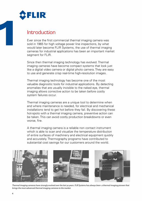
IntroductionEver since the first commercial thermal imaging camera was sold in 1965 for high voltage power line inspections, by what would later become FLIR Systems, the use of thermal imaging cameras for industrial applications has been an important market segment for FLIR.
Since then thermal imaging technology has evolved. Thermal imaging cameras have become compact systems that look just like a digital video camera or digital photo camera. They are easy to use and generate crisp real-time high-resolution images.
Thermal imaging technology has become one of the most valuable diagnostic tools for industrial applications. By detecting anomalies that are usually invisible to the naked eye, thermal imaging allows corrective action to be taken before costly system failures occur.
Thermal imaging cameras are a unique tool to determine when and where maintenance is needed, for electrical and mechanical installations tend to get hot before they fail. By discovering these hot-spots with a thermal imaging camera, preventive action can be taken. This can avoid costly production breakdowns or even worse, fire.
A thermal imaging camera is a reliable non contact instrument which is able to scan and visualize the temperature distribution of entire surfaces of machinery and electrical equipment quickly and accurately. Thermography programs have contributed to substantial cost savings for our customers around the world.
1
4
Thermal imaging cameras have strongly evolved over the last 50 years. FLIR Systems has always been a thermal imaging pioneer that brings the most advanced thermal imaging cameras to the market.
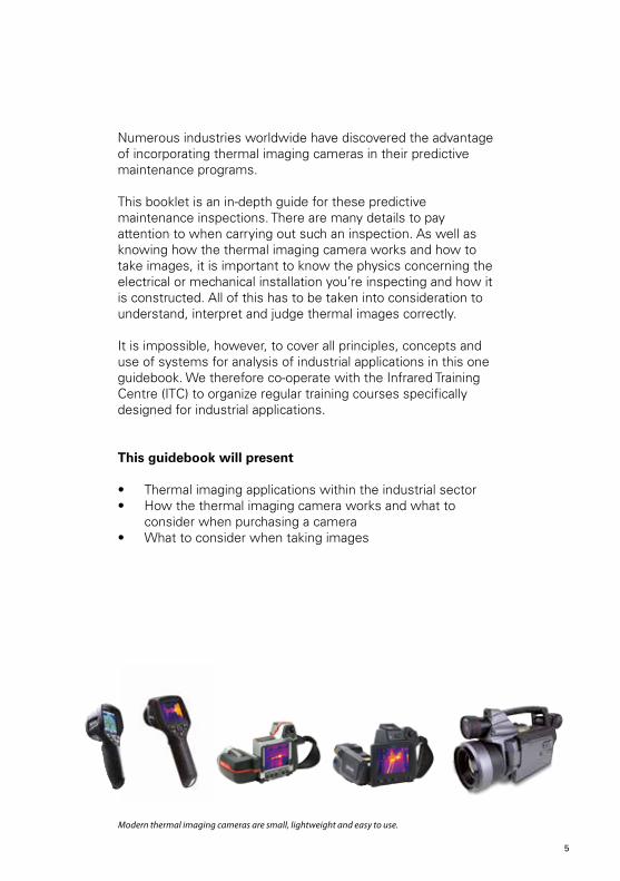
Numerous industries worldwide have discovered the advantage of incorporating thermal imaging cameras in their predictive maintenance programs.
This booklet is an in-depth guide for these predictive maintenance inspections. There are many details to pay attention to when carrying out such an inspection. As well as knowing how the thermal imaging camera works and how to take images, it is important to know the physics concerning the electrical or mechanical installation you’re inspecting and how it is constructed. All of this has to be taken into consideration to understand, interpret and judge thermal images correctly.
It is impossible, however, to cover all principles, concepts and use of systems for analysis of industrial applications in this one guidebook. We therefore co-operate with the Infrared Training Centre (ITC) to organize regular training courses specifically designed for industrial applications.
This guidebook will present
• Thermal imaging applications within the industrial sector• How the thermal imaging camera works and what to
consider when purchasing a camera• What to consider when taking images
4 5
Modern thermal imaging cameras are small, lightweight and easy to use.

The thermal imaging cameraand how it worksA thermal imaging camera records the intensity of radiation in the infrared part of the electromagnetic spectrum and converts it to a visible image.
What is infrared?Our eyes are detectors that are designed to detect electromagnetic radiation in the visible light spectrum. All other forms of electromagnetic radiation, such as infrared, are invisible to the human eye.
The existence of infrared was discovered in 1800 by astronomer Sir Frederick William Herschel. Curious to the thermal difference between different light colors, he directed sunlight through a glass prism to create a spectrum and then measured the temperature of each color. He found that the temperatures of the colors increased from the violet to the red part of the spectrum.
After noticing this pattern Herschel decided to measure the temperature just beyond the red portion of the spectrum in a region where no sunlight was visible. To his surprise, he found that this region had the highest temperature of all.
1
Sir William Herschel discovered infrared radiation in 1800.
6

Infrared radiation lies between the visible and microwave portions of the electromagnetic spectrum. The primary source of infrared radiation is heat or thermal radiation. Any object that has a temperature above absolute zero (-273.15 degrees Celsius or 0 Kelvin) emits radiation in the infrared region. Even objects that we think of as being very cold, such as ice cubes, emit infrared radiation.
We experience infrared radiation every day. The heat that we feel from sunlight, a fire or a radiator is all infrared. Although our eyes cannot see it, the nerves in our skin can feel it as heat. The warmer the object, the more infrared radiation it emits.
The thermal imaging cameraInfrared energy (A) coming from an object is focused by the optics (B) onto an infrared detector (C). The detector sends the information to sensor electronics (D) for image processing. The electronics translate the data coming from the detector into an image (E) that can be viewed in the viewfinder or on a standard video monitor or LCD screen.
Infrared thermography is the art of transforming an infrared image into a radiometric one, which allows temperature values to be read from the image. So every pixel in the radiometric image is in fact a temperature measurement. In order to do this, complex algorithms are incorporated into the thermal imaging camera. This makes the thermal imaging camera a perfect tool for industrial applications.
A BC D
E
E
6 7
GammaRays
X-Rays Ultra-Violet
Visible
Infrared
Microwaves
Radio
UHF VHF
Visible Infrared
2 5 8 12 micrometers
SW LW

2 Why use thermal imaging?Producing faster, better, more efficiently and at a lower cost. In order to reach these goals, industrial plants need to be running continuously: 24 hours a day, 365 days a year.
No costly breakdowns, no waste of time.
So, when you are in charge of plant predictive maintenance you really have a lot of responsibility on your shoulders.
If you could only see when components are about to fail, you could accurately decide the best time to take corrective action. Unfortunately the worst problems remain hidden until it is too late.
Thermal imaging cameras are the perfect tool for predicting failures because they make the invisible visible. On a thermal image problems seem to jump right out at you.
To keep plants operational at all times many industries have combined their predictive maintenance programs with the most valuable diagnostic tools for industrial applications on the market: thermal imaging cameras.
8
Inspection of high voltage power lines
Incorrectly secured connection
Internal fuse damagePoor connection and internal damage
Overheated motorSuspected roller
Steam trapDamaged insulation
Whether you’re monitoring high voltage equipment, low voltage cabinets, motors, pumps, high temperature equipment, looking for insulation losses… A thermal imaging camera is the one tool that really lets you SEE it all.
But what if you don’t do thermal inspections on a regular basis? Is it really that bad if a low voltage connection breaks down?
Aside from the production loss there is a greater danger.
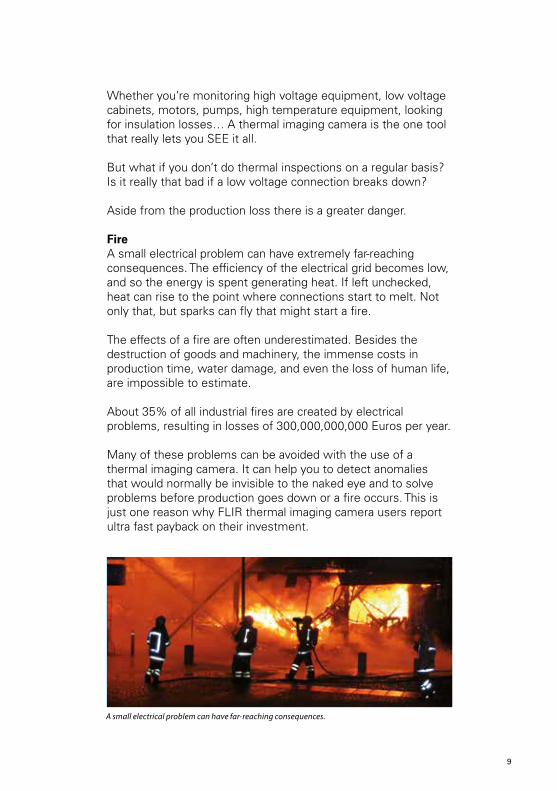
Fire A small electrical problem can have extremely far-reaching consequences. The efficiency of the electrical grid becomes low, and so the energy is spent generating heat. If left unchecked, heat can rise to the point where connections start to melt. Not only that, but sparks can fly that might start a fire.
The effects of a fire are often underestimated. Besides the destruction of goods and machinery, the immense costs in production time, water damage, and even the loss of human life, are impossible to estimate.
About 35% of all industrial fires are created by electrical problems, resulting in losses of 300,000,000,000 Euros per year.
Many of these problems can be avoided with the use of a thermal imaging camera. It can help you to detect anomalies that would normally be invisible to the naked eye and to solve problems before production goes down or a fire occurs. This is just one reason why FLIR thermal imaging camera users report ultra fast payback on their investment.
8 9
A small electrical problem can have far-reaching consequences.
Why use thermal imaging cameras?
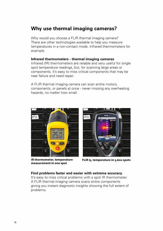
Why would you choose a FLIR thermal imaging camera? There are other technologies available to help you measure temperatures in a non-contact mode. Infrared thermometers for example.
Infrared thermometers - thermal imaging camerasInfrared (IR) thermometers are reliable and very useful for single spot temperature readings, but, for scanning large areas or components, it’s easy to miss critical components that may be near failure and need repair.
A FLIR thermal imaging camera can scan entire motors, components, or panels at once - never missing any overheating hazards, no matter how small.
Find problems faster and easier with extreme accuracy.It’s easy to miss critical problems with a spot IR thermometer. A FLIR thermal imaging camera scans entire components giving you instant diagnostic insights showing the full extent of problems.
IR thermometer, temperature measurement in one spot
FLIR i3, temperature in 3,600 spots
10

What an IR Thermometer sees.
What an IR Thermometer sees.
What an IR Thermometer sees.
What a thermal imaging camera sees.
What a thermal imaging camera sees.
What a thermal imaging camera sees.
Use thousands of infrared thermometers at the same timeWith an infrared thermometer you are able to measure the temperature at one single spot. FLIR thermal imaging cameras can measure temperatures on the entire image. The FLIR i3 has an image resolution of 60 x 60 pixels. This means that it is equal to using 3,600 IR thermometers at the same time. If we look at the FLIR P660, our top model, which has an image resolution of 640 x 480 pixels, this means 307,200 pixels or using 307,200 infrared thermometers at the same time.
10 11
Using thermal imaging for industrial applicationsThermal imaging cameras for industrial applications are powerful and non invasive tools for monitoring and diagnosing the condition of electrical and mechanical installations and components. With a thermal imaging camera you can identify problems early, allowing them to be documented and corrected before becoming more serious and more costly to repair.
FLIR thermal imaging cameras:• Areaseasytouseasacamcorderoradigitalcamera• Giveyouafullimageofthesituation• Allowyoutoperforminspectionswhensystemsareunderload• Identifyandlocatetheproblem• Measuretemperatures• Storeinformation• Tellyouexactlywhatneedstobefixed• Helpyoufindfaultsbeforerealproblemsoccur• Saveyouvaluabletimeandmoney
FLIR Systems offers a wide range of thermal imaging cameras. Whether you use thermal imaging for an inspection of large industrial installations or for an inspection of a fuse box in a domestic residence, FLIR will have just the right thermal imaging camera for you.
A thermal image that includes accurate temperature data provides the maintenance expert with important information about the condition of the inspected equipment. These inspections can be done with the production process in full operation and in many cases the use of a thermal imaging camera can even help optimize the production process itself.
Thermal imaging cameras are such a valuable and versatile tool that we cannot possibly list all the possible applications. New and innovative ways of using the technology are being developed every day. Some of the many ways in which thermal imaging cameras can be used within the range of industrial applications are explained in this section of the guide.
3
12
Electrical systemsThermal imaging cameras are commonly used for inspections of electrical systems and components in all sizes and shapes.
The multitude of possible applications for thermal imaging cameras within the range of electrical systems can be divided into two categories: high voltage and low voltage installations.
High voltage installationsHeat is an important factor in high voltage installations. When electrical current passes through a resistive element, it generates heat. An increased resistance results in an increase in heat.
Over time the resistance of electrical connections will increase, due to loosening and corrosion for instance. The corresponding rise in temperature can cause components to fail, resulting in unplanned outages and even injuries. In addition, the energy spent on generating heat causes unnecessary energy losses. If left unchecked, the heat can even rise to the point where connections melt and break down; as a result, fires may break out.
Examples of failures in high-voltage installations that can be detected with thermal imaging:• Oxidation of high voltage switches• Overheated connections• Incorrectly secured connections• Insulator defects
These and other issues can be spotted at an early stage with a thermal imaging camera. A thermal imaging camera will help you to accurately locate the problem, determine the severity of the problem, and establish the time frame in which the equipment should be repaired.
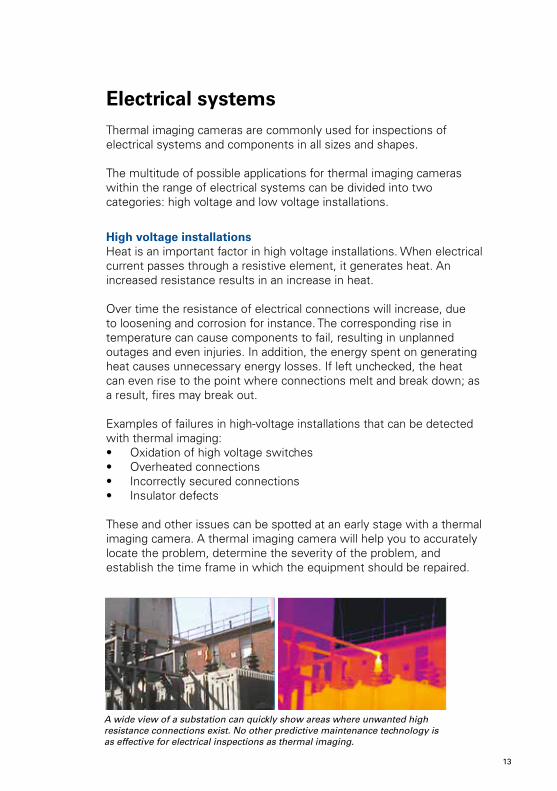
A wide view of a substation can quickly show areas where unwanted high resistance connections exist. No other predictive maintenance technology is as effective for electrical inspections as thermal imaging.
12 13
One of the many advantages of thermal imaging is the ability to perform inspections while electrical systems are under load. Since thermal imaging is a non-contact diagnostic method, a thermographer can quickly scan a particular piece of equipment from a safe distance, leave the hazardous area, return to his office and analyze the data without ever putting himself in harm’s way.
Due to the fact that FLIR’s thermal imaging cameras for industrial applications are all handheld and battery operated, they can also be used for outdoor inspections: high voltage substations, switchgear, transformers, and outdoor circuit breakers can be inspected quickly and efficiently with a thermal imaging camera from FLIR Systems.
Thermal imaging cameras allow you to inspect high voltage installations from a safe distance, increasing worker safety.
Continuity is very important to utilities since many people rely on their services. Therefore thermal imaging inspections have become the core of utility predictive maintenance programs throughout the world.
FLIR can provide the most advanced thermal imaging solutions to support 24/7 monitoring programs that keep the vital electrical power grid up and running.
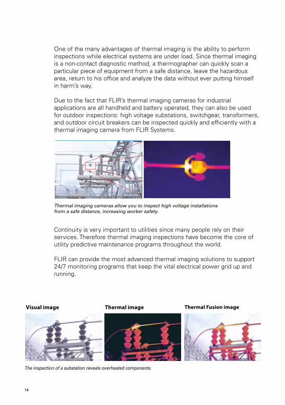
The inspection of a substation reveals overheated components.
Thermal Fusion imageVisual image Thermal image
14

Low voltage installationsThermal imaging cameras are used for inspections of electrical systems and components in all sizes and shapes and their use is by no means limited to large high voltage applications alone.
Electrical cabinets and motor control centers are regularly scanned with a thermal imaging camera. If left unchecked, heat can rise to a point that connections melt and break down; as a result, fires may break out. Besides loose connections, electrical systems suffer from load imbalances, corrosion, and increases in impedance to current. Thermal inspections can quickly locate hot spots, determine the severity of the problem, and help establish the time frame in which the equipment should be repaired.
Examples of failures in low voltage equipment that can be detected with thermal imaging:• High resistance connections• Corroded connections• Internal fuse damage• Internal circuit breaker faults• Poor connections and internal damage
These and other issues can be spotted at an early stage with a thermal imaging camera. This will help to prevent costly damages and to avoid dangerous situations.
Overheated connection Overheated connection
This thermal image shows that the load is not distributed evenly among the fuse boxes.
14 15
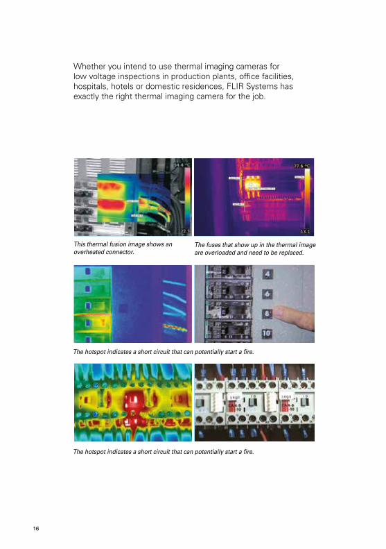
This thermal fusion image shows an overheated connector.
The fuses that show up in the thermal image are overloaded and need to be replaced.
The hotspot indicates a short circuit that can potentially start a fire.
The hotspot indicates a short circuit that can potentially start a fire.
Whether you intend to use thermal imaging cameras for low voltage inspections in production plants, office facilities, hospitals, hotels or domestic residences, FLIR Systems has exactly the right thermal imaging camera for the job.
16
Mechanical Installations
In many industries, mechanical systems serve as the backbone of operations.
Thermal data collected with a thermal imaging camera can be an invaluable source of complimentary information to vibration studies in mechanical equipment monitoring.
Mechanical systems will heat up if there is a misalignment at some point in the system.
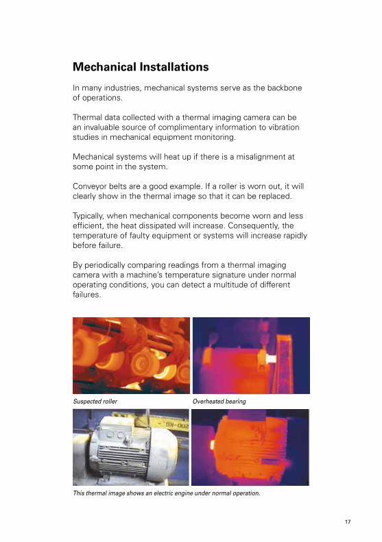
Conveyor belts are a good example. If a roller is worn out, it will clearly show in the thermal image so that it can be replaced.
Typically, when mechanical components become worn and less efficient, the heat dissipated will increase. Consequently, the temperature of faulty equipment or systems will increase rapidly before failure.
By periodically comparing readings from a thermal imaging camera with a machine’s temperature signature under normal operating conditions, you can detect a multitude of different failures.
16 17
This thermal image shows an electric engine under normal operation.
Suspected roller Overheated bearing

Motors can also be inspected with a thermal imaging camera. Motor failures like brush contact-wear and armature shorts typically produce excess heat prior to failure but remain undetected with vibration analysis, since it often causes little to no extra vibration. Thermal imaging gives a full overview and allows you to compare the temperature of different motors.
Other mechanical systems monitored with thermal imaging cameras include couplings, gearboxes, bearings, pumps, compressors, belts, blowers and conveyor systems.
Examples of mechanical faults that can be detected with thermal imaging are:• Lubrication issues• Misalignments• Overheated motors• Suspect rollers• Overloaded pumps• Overheated motor axles• Hot bearings
These and other issues can be spotted at an early stage with a thermal imaging camera. This will help to prevent costly damages and to ensure the continuity of production.
Motor: Bearing Problem.
Motor: Internal Winding Problem.
18
Pipework
Thermal imaging also gives valuable information about the condition of pipe, tube and valve insulation.
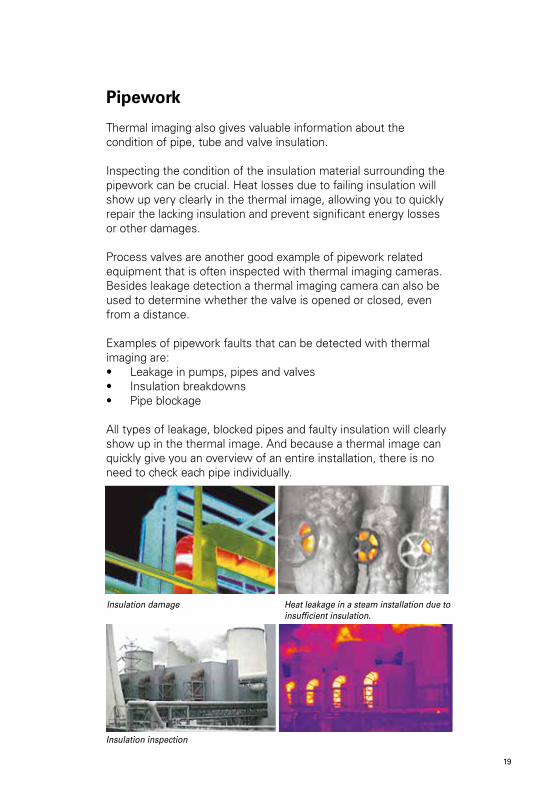
Inspecting the condition of the insulation material surrounding the pipework can be crucial. Heat losses due to failing insulation will show up very clearly in the thermal image, allowing you to quickly repair the lacking insulation and prevent significant energy losses or other damages.
Process valves are another good example of pipework related equipment that is often inspected with thermal imaging cameras. Besides leakage detection a thermal imaging camera can also be used to determine whether the valve is opened or closed, even from a distance.
Examples of pipework faults that can be detected with thermal imaging are:• Leakage in pumps, pipes and valves• Insulation breakdowns• Pipe blockage
All types of leakage, blocked pipes and faulty insulation will clearly show up in the thermal image. And because a thermal image can quickly give you an overview of an entire installation, there is no need to check each pipe individually.
18 19
Insulation inspection
Heat leakage in a steam installation due to insufficient insulation.
Insulation damage
Refractory and petrochemical installations
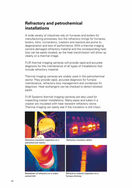
A wide variety of industries rely on furnaces and boilers for manufacturing processes, but the refractory linings for furnaces, boilers, kilns, incinerators, crackers and reactors are prone to degeneration and loss of performance. With a thermal imaging camera damaged refractory material and the corresponding heat loss can be easily located, as the heat transmission will show up clearly on a thermal image.
FLIR thermal imaging cameras will provide rapid and accurate diagnosis for the maintenance of all types of installations that include refractory material.
Thermal imaging cameras are widely used in the petrochemical sector. They provide rapid, accurate diagnosis for furnace maintenance, refractory loss management and condenser fin diagnosis. Heat exchangers can be checked to detect blocked pipes.
FLIR Systems thermal imaging cameras are also used for inspecting cracker installations. Many pipes and tubes in a cracker are insulated with heat resistant refractory stone. Thermal imaging can easily see if the insulation is still intact.
Refractory material inspection on a furnace chimney.
Breakdown of refractory on a rotary cement kiln
Refractory insulation inspection on a petrochemical reactor
Refractory insulation defect
20

But furnace and boiler equipment is also prone to failures from a variety of other mechanisms. These include coking that plugs the inside of tubes and impedes product flow, slag build-up on the outside of tubes, under and overheating, flame impingement on tubes due to burner misalignment, and product leaks that ignite and cause serious damage to the equipment.
Seeing through the flamesTo ensure refractory quality of boiler and furnace installations it is not enough to just perform inspections from the outside. The refractory on the inside of the boiler or furnace has to be inspected as well. With conventional methods it is necessary to shut down the installation to be able to inspect the inside. This is extremely costly due to a loss of production during downtime. These losses are not necessary, however, for FLIR Systems also has special thermal imaging cameras that can be used to inspect the inside of the installation during operation.
This is possible due to the flame filter FLIR has included in the design of these thermal imaging cameras. Flames emit infrared radiation at different intensities at different wavelengths and at certain wavelengths in the infrared spectrum flames emit hardly any thermal radiation at all. A flame filter uses that fact to enable the thermal imaging camera to ‘see’ through the flames.
The ability of these FLIR thermal imaging cameras to ‘see’ through flames allows the operator to inspect the boiler or furnace installation during full operation. Not only does this eliminate the need for downtime during inspections, the information gathered with the thermal imaging camera can also be an extremely important control mechanism for safely increasing the production level, which can drastically improve the installation’s yield.
Some FLIR thermal imaging cameras can measure the temperatures behind the flames.
20 21
Other applications
Apart from the applications already mentioned there are numerous other applications where thermal imaging technology is being used.
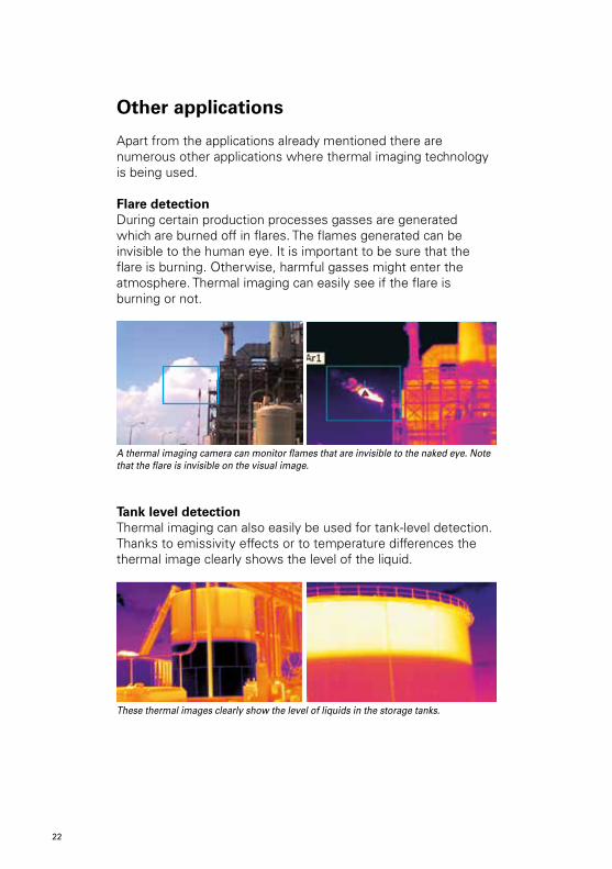
Flare detectionDuring certain production processes gasses are generated which are burned off in flares. The flames generated can be invisible to the human eye. It is important to be sure that the flare is burning. Otherwise, harmful gasses might enter the atmosphere. Thermal imaging can easily see if the flare is burning or not.
A thermal imaging camera can monitor flames that are invisible to the naked eye. Note that the flare is invisible on the visual image.
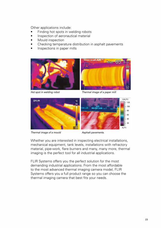
Tank level detectionThermal imaging can also easily be used for tank-level detection. Thanks to emissivity effects or to temperature differences the thermal image clearly shows the level of the liquid.
These thermal images clearly show the level of liquids in the storage tanks.
22
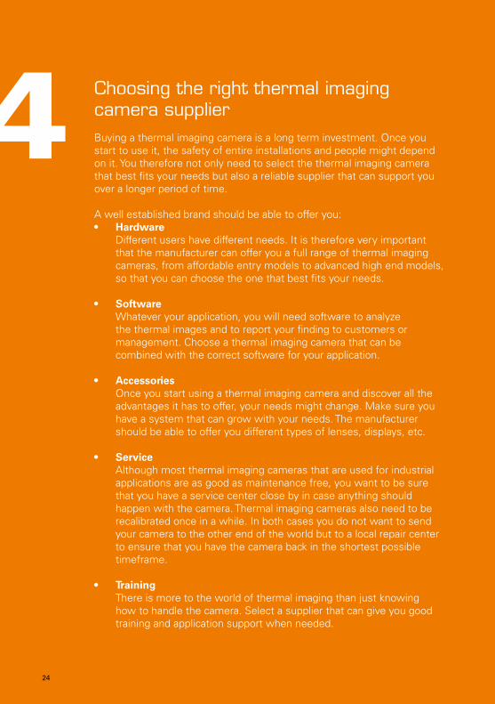
Other applications include:• Finding hot spots in welding robots• Inspection of aeronautical material• Mould inspection• Checking temperature distribution in asphalt pavements• Inspections in paper mills
Hot spot in welding robot Thermal image of a paper mill
Thermal image of a mould Asphalt pavements.
Whether you are interested in inspecting electrical installations, mechanical equipment, tank levels, installations with refractory material, pipe-work, flare burners and many, many more, thermal imaging is the perfect tool for all industrial applications.
FLIR Systems offers you the perfect solution for the most demanding industrial applications. From the most affordable to the most advanced thermal imaging camera model, FLIR Systems offers you a full product range so you can choose the thermal imaging camera that best fits your needs.
22 23
Choosing the right thermal imaging camera supplierBuying a thermal imaging camera is a long term investment. Once you start to use it, the safety of entire installations and people might depend on it. You therefore not only need to select the thermal imaging camera that best fits your needs but also a reliable supplier that can support you over a longer period of time.
A well established brand should be able to offer you:• Hardware
Different users have different needs. It is therefore very important that the manufacturer can offer you a full range of thermal imaging cameras, from affordable entry models to advanced high end models, so that you can choose the one that best fits your needs.
• Software Whatever your application, you will need software to analyze the thermal images and to report your finding to customers or management. Choose a thermal imaging camera that can be combined with the correct software for your application.
• Accessories Once you start using a thermal imaging camera and discover all the advantages it has to offer, your needs might change. Make sure you have a system that can grow with your needs. The manufacturer should be able to offer you different types of lenses, displays, etc.
• Service Although most thermal imaging cameras that are used for industrial applications are as good as maintenance free, you want to be sure that you have a service center close by in case anything should happen with the camera. Thermal imaging cameras also need to be recalibrated once in a while. In both cases you do not want to send your camera to the other end of the world but to a local repair center to ensure that you have the camera back in the shortest possible timeframe.
• Training There is more to the world of thermal imaging than just knowing how to handle the camera. Select a supplier that can give you good training and application support when needed.
4
24
24 25

Thermal physics for industrial applicationsIn order to interpret the thermal images correctly the operator needs to know how different materials and circumstances influence the temperature readings from the thermal imaging camera. Some of the most important factors influencing the temperature readings are:
1. Thermal conductivityDifferent materials have different thermal properties. Insulation tends to warm up slowly, while metals tend to warm up quickly, for instance. This is called thermal conductivity. Difference in thermal conductivity in two different materials can lead to large temperature differences in certain situations.
2. Emissivity To read correct temperatures, one important thing needs to be taken into account, and that is a factor known as emissivity. Emissivity is the efficiency with which an object emits infrared radiation. This is highly dependent on material properties.
5
If you look at the thermal image you might think that the gold paint is colder than the mug surface. In reality they have exactly the same temperature, the difference in intensity of infrared radiation is caused by a difference in emissivity.
26
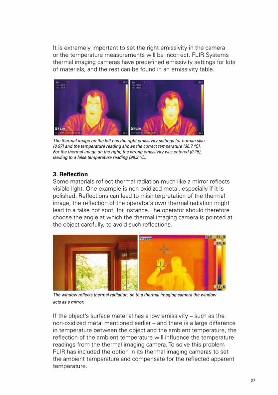
It is extremely important to set the right emissivity in the camera or the temperature measurements will be incorrect. FLIR Systems thermal imaging cameras have predefined emissivity settings for lots of materials, and the rest can be found in an emissivity table.
The thermal image on the left has the right emissivity settings for human skin (0.97) and the temperature reading shows the correct temperature (36.7 °C). For the thermal image on the right, the wrong emissivity was entered (0.15), leading to a false temperature reading (98.3 °C).
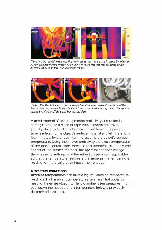
3. ReflectionSome materials reflect thermal radiation much like a mirror reflects visible light. One example is non-oxidized metal, especially if it is polished. Reflections can lead to misinterpretation of the thermal image, the reflection of the operator’s own thermal radiation might lead to a false hot spot, for instance. The operator should therefore choose the angle at which the thermal imaging camera is pointed at the object carefully, to avoid such reflections.
The window reflects thermal radiation, so to a thermal imaging camera the window
acts as a mirror.
If the object’s surface material has a low emissivity – such as the non-oxidized metal mentioned earlier – and there is a large difference in temperature between the object and the ambient temperature, the reflection of the ambient temperature will influence the temperature readings from the thermal imaging camera. To solve this problem FLIR has included the option in its thermal imaging cameras to set the ambient temperature and compensate for the reflected apparent temperature.
26 27
A good method of ensuring correct emissivity and reflection settings is to use a piece of tape with a known emissivity (usually close to 1), also called ‘calibration tape’. This piece of tape is affixed to the object’s surface material and left there for a few minutes, long enough for it to assume the object’s surface temperature. Using the known emissivity the exact temperature of the tape is determined. Because this temperature is the same as that of the surface material, the operator can then change the emissivity settings (and the reflection settings if applicable) so that the temperature reading is the same as the temperature reading form the calibration tape a moment ago.
4. Weather conditionsAmbient temperatures can have a big influence on temperature readings. High ambient temperatures can mask hot spots by heating the entire object, while low ambient temperatures might cool down the hot spots to a temperature below a previously determined threshold.
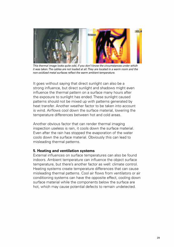
These two ‘hot spots’ might look like warm areas, but this is actually cause by reflection by non-oxidized metal surfaces. A tell-tale sign is the fact that real hot spots usually display a smooth pattern, but reflections do not.
The fact that the ‘hot spot’ in the middle picture disappears when the location of the thermal imaging camera is slightly altered clearly shows that this apparent ‘hot spot’ is caused by reflection. This is another tell-tale sign.
28
This thermal image looks quite odd, if you don’t know the circumstances under which it was taken. The cables are not loaded at all. They are located in a warm room and the non-oxidized metal surfaces reflect the warm ambient temperature.
It goes without saying that direct sunlight can also be a strong influence, but direct sunlight and shadows might even influence the thermal pattern on a surface many hours after the exposure to sunlight has ended. These sunlight caused patterns should not be mixed up with patterns generated by heat transfer. Another weather factor to be taken into account is wind. Airflows cool down the surface material, lowering the temperature differences between hot and cold areas.
Another obvious factor that can render thermal imaging inspection useless is rain, it cools down the surface material. Even after the rain has stopped the evaporation of the water cools down the surface material. Obviously this can lead to misleading thermal patterns.
5. Heating and ventilation systemsExternal influences on surface temperatures can also be found indoors. Ambient temperature can influence the object surface temperature, but there’s another factor as well: climate control. Heating systems create temperature differences that can cause misleading thermal patterns. Cool air flows from ventilators or air conditioning systems can have the opposite effect, cooling down surface material while the components below the surface are hot, which may cause potential defects to remain undetected.
28 29
Finding the Best SolutionBasically six key requirements are important to evaluate when investigating a suitable combination of thermal imaging camera, software and training:
1. Camera resolution / image quality2. Thermal sensitivity3. Accuracy4. Camera functions5. Software6. Training demands
1. Camera ResolutionImage quality or camera resolution is an important factor. The most affordable entry models have a resolution of 60 x 60 pixels, while the advanced high end models have a resolution of 640 x 480 pixels.
The thermal imaging cameras with a 320 x 240 or 640 x 480 pixels resolution deliver superior image quality. For more advanced inspections the 640 x 480 pixel resolution is becoming the standard for professional thermographers.
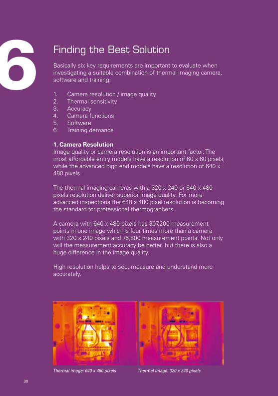
A camera with 640 x 480 pixels has 307,200 measurement points in one image which is four times more than a camera with 320 x 240 pixels and 76,800 measurement points. Not only will the measurement accuracy be better, but there is also a huge difference in the image quality.
High resolution helps to see, measure and understand more accurately.
6
Thermal image: 640 x 480 pixels Thermal image: 320 x 240 pixels
30
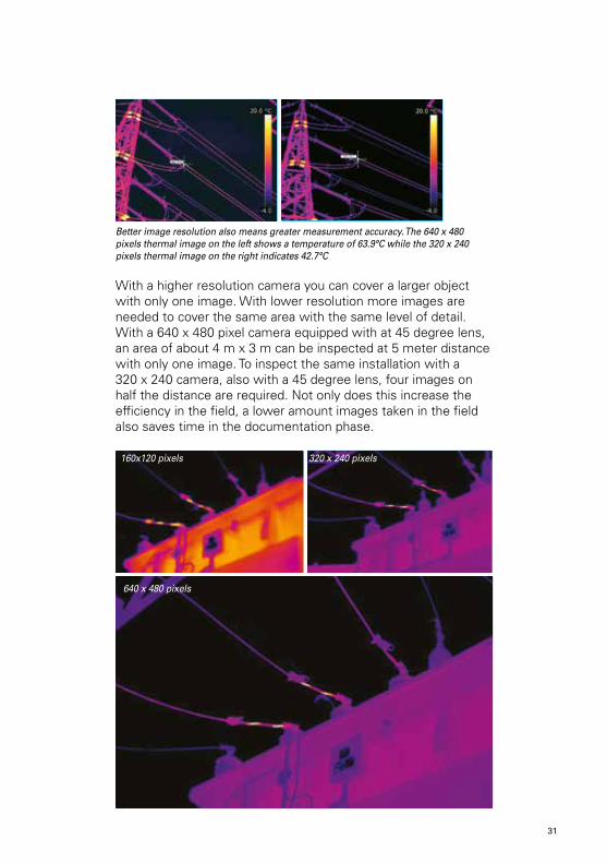
With a higher resolution camera you can cover a larger object with only one image. With lower resolution more images are needed to cover the same area with the same level of detail. With a 640 x 480 pixel camera equipped with at 45 degree lens, an area of about 4 m x 3 m can be inspected at 5 meter distance with only one image. To inspect the same installation with a 320 x 240 camera, also with a 45 degree lens, four images on half the distance are required. Not only does this increase the efficiency in the field, a lower amount images taken in the field also saves time in the documentation phase.
Better image resolution also means greater measurement accuracy. The 640 x 480 pixels thermal image on the left shows a temperature of 63.9°C while the 320 x 240 pixels thermal image on the right indicates 42.7°C
320 x 240 pixels
3130
160x120 pixels
640 x 480 pixels
2. Thermal SensitivityThermal sensitivity describes how small a temperature difference the camera can detect. The better the thermal sensitivity, the smaller the minimum temperature difference the thermal imaging camera can pick up and visualize. Usually the thermal sensitivity is described in °C or mK. The most advanced thermal imaging cameras for industrial applications will have a thermal sensitivity of 0.03°C (30 mK).
Being able to detect these minute temperature differences is important in most thermal imaging applications. High camera sensitivity is particularly important for industrial applications where temperature differences are low. These small temperature differences can be crucial information both for diagnosing the problem and for planning further actions.
3. AccuracyAll measurements are susceptible to error, and unfortunately thermal imaging temperature measurements are no exception. This is where the thermal imaging accuracy comes into play.
In thermal imaging fact sheets the accuracy is expressed both in percentages and degrees Celsius. This is the margin of error within which the camera will operate. The measured temperature might vary from the actual temperature with either the mentioned percentage or absolute temperature, whichever is bigger.
The current industry standard for accuracy is ±2% / ±2°C. The more advanced thermal imaging cameras from FLIR Systems score even better: ±1% / ±1°C.
Sensitivity0.03°C
32
4. Camera functions
Emissivity and reflectionAs discussed in the previous chapter, the emissivity of the object is a very important parameter that has to be taken into account. All FLIR thermal imaging cameras for industrial applications allow the operator to set the emissivity and reflection. Being able to set the parameters emissivity and reflection makes a huge difference. When buying a thermal imaging camera you should make sure that these functions are included in the design.
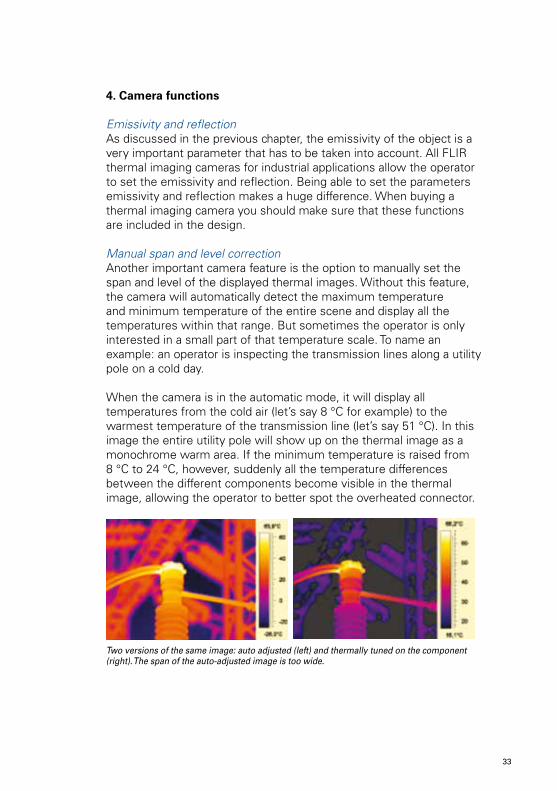
Manual span and level correctionAnother important camera feature is the option to manually set the span and level of the displayed thermal images. Without this feature, the camera will automatically detect the maximum temperature and minimum temperature of the entire scene and display all the temperatures within that range. But sometimes the operator is only interested in a small part of that temperature scale. To name an example: an operator is inspecting the transmission lines along a utility pole on a cold day.
When the camera is in the automatic mode, it will display all temperatures from the cold air (let’s say 8 °C for example) to the warmest temperature of the transmission line (let’s say 51 °C). In this image the entire utility pole will show up on the thermal image as a monochrome warm area. If the minimum temperature is raised from 8 °C to 24 °C, however, suddenly all the temperature differences between the different components become visible in the thermal image, allowing the operator to better spot the overheated connector.
Two versions of the same image: auto adjusted (left) and thermally tuned on the component (right). The span of the auto-adjusted image is too wide.
32 33
Thermal image Visual image
Digital cameraSometimes it can be very difficult to see what components are shown in a thermal image, especially in complicated situations with a lot of components shown in one image, or when you are taking close up pictures. In such cases it can help a great deal if you also take a visible light picture of the subject to help you locate the components in the thermal image. To that end most of FLIR’s thermal imaging cameras for industrial applications have a built in digital camera. Most predictive maintenance professionals that use thermal imaging cameras claim that they always take a visible light picture as well, to make sure that they know what is shown in the thermal image.
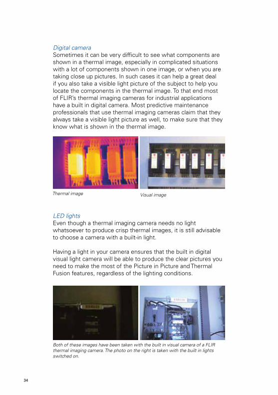
LED lightsEven though a thermal imaging camera needs no light whatsoever to produce crisp thermal images, it is still advisable to choose a camera with a built-in light.
Having a light in your camera ensures that the built in digital visual light camera will be able to produce the clear pictures you need to make the most of the Picture in Picture and Thermal Fusion features, regardless of the lighting conditions.
Both of these images have been taken with the built in visual camera of a FLIR thermal imaging camera. The photo on the right is taken with the built in lights switched on.
34
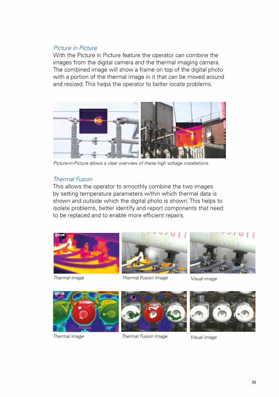
Picture-in-Picture allows a clear overview of these high voltage installations.
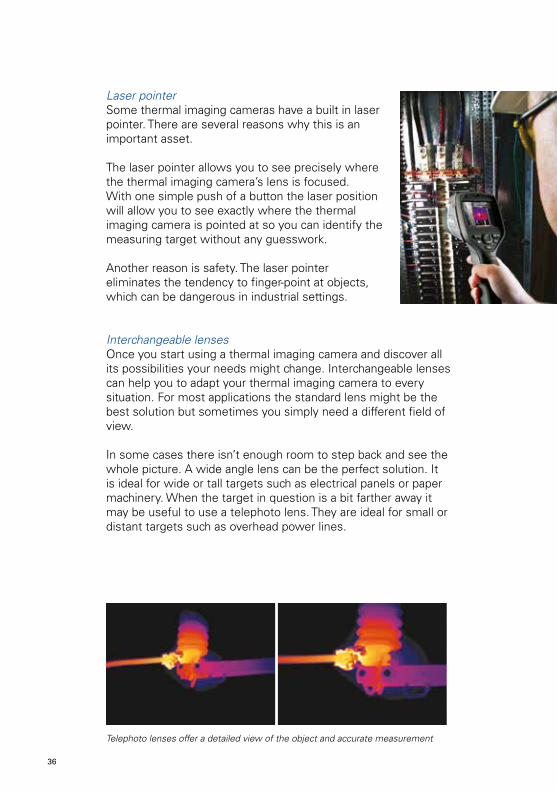
Thermal image Visual imageThermal Fusion Image
Thermal image Visual imageThermal Fusion Image
Picture in PictureWith the Picture in Picture feature the operator can combine the images from the digital camera and the thermal imaging camera. The combined image will show a frame on top of the digital photo with a portion of the thermal image in it that can be moved around and resized. This helps the operator to better locate problems.
Thermal FusionThis allows the operator to smoothly combine the two images by setting temperature parameters within which thermal data is shown and outside which the digital photo is shown. This helps to isolate problems, better identify and report components that need to be replaced and to enable more efficient repairs.
34 35
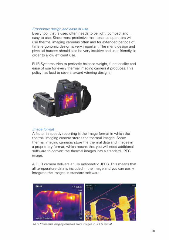
Laser pointerSome thermal imaging cameras have a built in laser pointer. There are several reasons why this is an important asset.
The laser pointer allows you to see precisely where the thermal imaging camera’s lens is focused. With one simple push of a button the laser position will allow you to see exactly where the thermal imaging camera is pointed at so you can identify the measuring target without any guesswork.
Another reason is safety. The laser pointer eliminates the tendency to finger-point at objects, which can be dangerous in industrial settings.
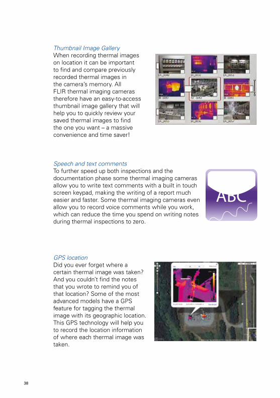
Interchangeable lensesOnce you start using a thermal imaging camera and discover all its possibilities your needs might change. Interchangeable lenses can help you to adapt your thermal imaging camera to every situation. For most applications the standard lens might be the best solution but sometimes you simply need a different field of view. In some cases there isn’t enough room to step back and see the whole picture. A wide angle lens can be the perfect solution. It is ideal for wide or tall targets such as electrical panels or paper machinery. When the target in question is a bit farther away it may be useful to use a telephoto lens. They are ideal for small or distant targets such as overhead power lines.
Telephoto lenses offer a detailed view of the object and accurate measurement
36
Ergonomic design and ease of useEvery tool that is used often needs to be light, compact and easy to use. Since most predictive maintenance operators will use thermal imaging cameras often and for extended periods of time, ergonomic design is very important. The menu design and physical buttons should also be very intuitive and user friendly, in order to allow efficient use.
FLIR Systems tries to perfectly balance weight, functionality and ease of use for every thermal imaging camera it produces. This policy has lead to several award winning designs.
Image formatA factor in speedy reporting is the image format in which the thermal imaging camera stores the thermal images. Some thermal imaging cameras store the thermal data and images in a proprietary format, which means that you will need additional software to convert the thermal images into a standard JPEG image.
A FLIR camera delivers a fully radiometric JPEG. This means that all temperature data is included in the image and you can easily integrate the images in standard software.
All FLIR thermal imaging cameras store images in JPEG format.
36 37
Thumbnail Image GalleryWhen recording thermal images on location it can be important to find and compare previously recorded thermal images in the camera’s memory. All FLIR thermal imaging cameras therefore have an easy-to-access thumbnail image gallery that will help you to quickly review your saved thermal images to find the one you want – a massive convenience and time saver!
Speech and text commentsTo further speed up both inspections and the documentation phase some thermal imaging cameras allow you to write text comments with a built in touch screen keypad, making the writing of a report much easier and faster. Some thermal imaging cameras even allow you to record voice comments while you work, which can reduce the time you spend on writing notes during thermal inspections to zero.
GPS locationDid you ever forget where a certain thermal image was taken? And you couldn’t find the notes that you wrote to remind you of that location? Some of the most advanced models have a GPS feature for tagging the thermal image with its geographic location. This GPS technology will help you to record the location information of where each thermal image was taken.
ABC
38
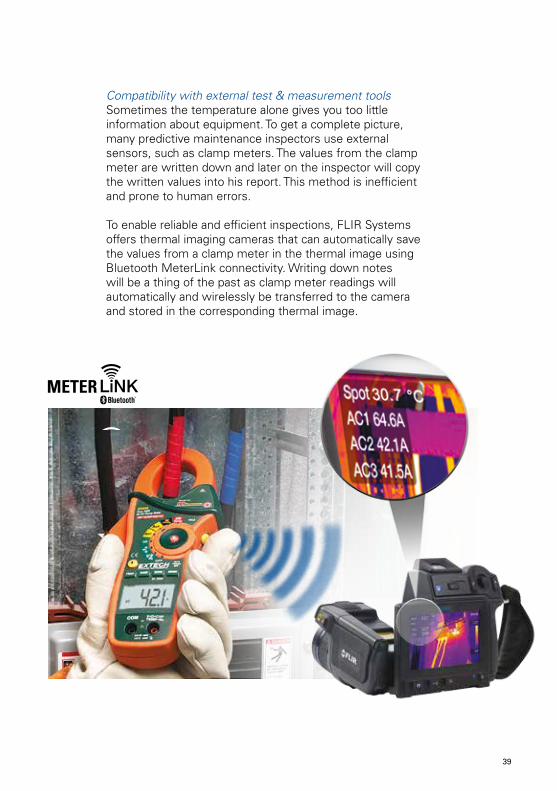
Compatibility with external test & measurement toolsSometimes the temperature alone gives you too little information about equipment. To get a complete picture, many predictive maintenance inspectors use external sensors, such as clamp meters. The values from the clamp meter are written down and later on the inspector will copy the written values into his report. This method is inefficient and prone to human errors.
To enable reliable and efficient inspections, FLIR Systems offers thermal imaging cameras that can automatically save the values from a clamp meter in the thermal image using Bluetooth MeterLink connectivity. Writing down notes will be a thing of the past as clamp meter readings will automatically and wirelessly be transferred to the camera and stored in the corresponding thermal image.
38 39
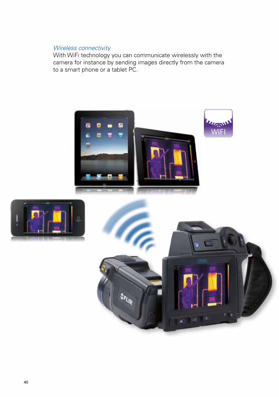
Wireless connectivityWith WiFi technology you can communicate wirelessly with the camera for instance by sending images directly from the camera to a smart phone or a tablet PC.
WIFI
40
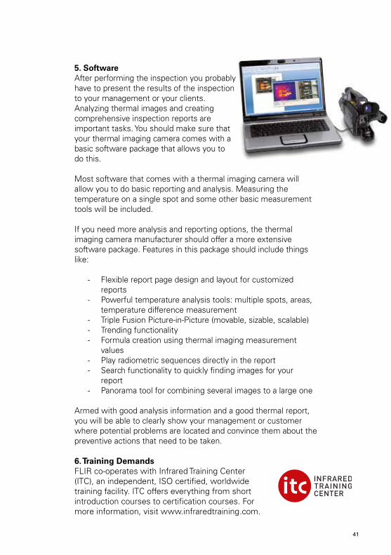
5. SoftwareAfter performing the inspection you probably have to present the results of the inspection to your management or your clients. Analyzing thermal images and creating comprehensive inspection reports are important tasks. You should make sure that your thermal imaging camera comes with a basic software package that allows you to do this. Most software that comes with a thermal imaging camera will allow you to do basic reporting and analysis. Measuring the temperature on a single spot and some other basic measurement tools will be included. If you need more analysis and reporting options, the thermal imaging camera manufacturer should offer a more extensive software package. Features in this package should include things like:
- Flexible report page design and layout for customized reports
- Powerful temperature analysis tools: multiple spots, areas, temperature difference measurement
- Triple Fusion Picture-in-Picture (movable, sizable, scalable)- Trending functionality- Formula creation using thermal imaging measurement
values- Play radiometric sequences directly in the report- Search functionality to quickly finding images for your
report- Panorama tool for combining several images to a large one
Armed with good analysis information and a good thermal report, you will be able to clearly show your management or customer where potential problems are located and convince them about the preventive actions that need to be taken.
6. Training DemandsFLIR co-operates with Infrared Training Center (ITC), an independent, ISO certified, worldwide training facility. ITC offers everything from short introduction courses to certification courses. For more information, visit www.infraredtraining.com.
40 41
How to carry out thermal inspectionsSo the thermal imaging camera has been delivered and the inspecting can begin. But where do you start? In this section of the guidebook some thermal imaging methods will be present in order to get you going.
1. Define the taskList all of the equipment you want to monitor. In many corporate settings such a list is already available; all you have to do is eliminate the items on the list that are not suited for thermal imaging inspections.
The next step would be to prioritize the list. Most companies keep maintenance and production records. These records will show which equipment is most prone to failure and therefore deserves close scrutiny. Also take into account the direct consequences of failure; vital equipment should be monitored more often and more closely than equipment that can be temporarily out of order without impeding functionality of the entire process.
Based on this information you can start setting up the schedules for the thermal inspections. But you’re not ready to start yet. There’s another vitally important step you should take first.
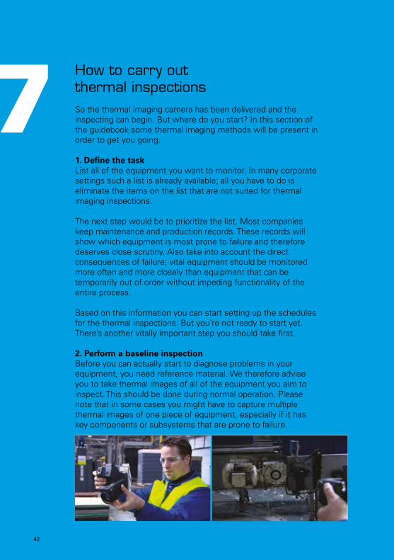
2. Perform a baseline inspectionBefore you can actually start to diagnose problems in your equipment, you need reference material. We therefore advise you to take thermal images of all of the equipment you aim to inspect. This should be done during normal operation. Please note that in some cases you might have to capture multiple thermal images of one piece of equipment, especially if it has key components or subsystems that are prone to failure.
7
42
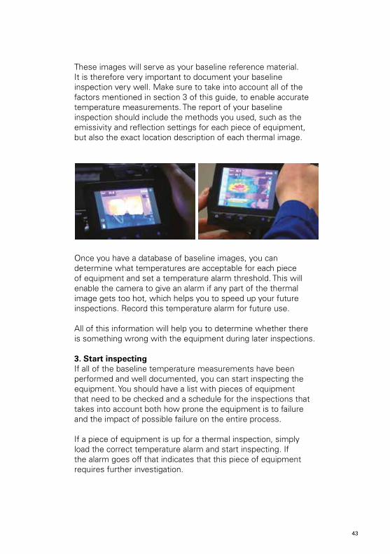
These images will serve as your baseline reference material. It is therefore very important to document your baseline inspection very well. Make sure to take into account all of the factors mentioned in section 3 of this guide, to enable accurate temperature measurements. The report of your baseline inspection should include the methods you used, such as the emissivity and reflection settings for each piece of equipment, but also the exact location description of each thermal image.
Once you have a database of baseline images, you can determine what temperatures are acceptable for each piece of equipment and set a temperature alarm threshold. This will enable the camera to give an alarm if any part of the thermal image gets too hot, which helps you to speed up your future inspections. Record this temperature alarm for future use.
All of this information will help you to determine whether there is something wrong with the equipment during later inspections.
3. Start inspectingIf all of the baseline temperature measurements have been performed and well documented, you can start inspecting the equipment. You should have a list with pieces of equipment that need to be checked and a schedule for the inspections that takes into account both how prone the equipment is to failure and the impact of possible failure on the entire process.
If a piece of equipment is up for a thermal inspection, simply load the correct temperature alarm and start inspecting. If the alarm goes off that indicates that this piece of equipment requires further investigation.
42 43
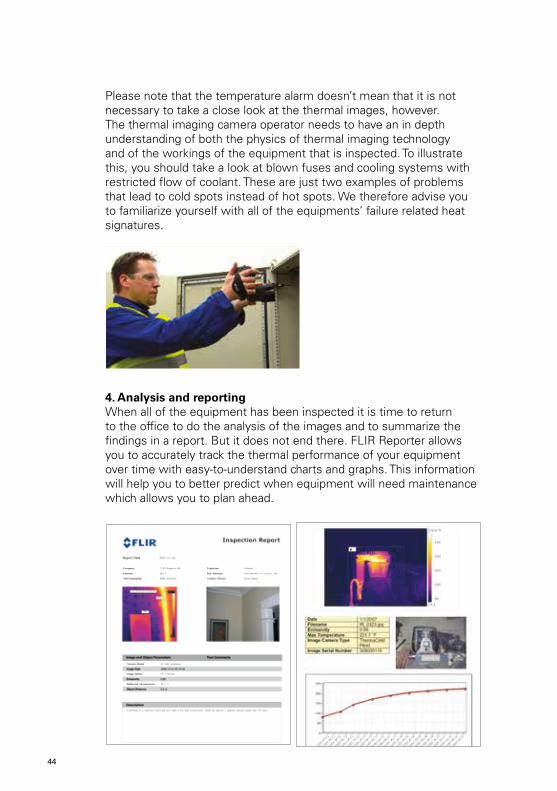
Please note that the temperature alarm doesn’t mean that it is not necessary to take a close look at the thermal images, however. The thermal imaging camera operator needs to have an in depth understanding of both the physics of thermal imaging technology and of the workings of the equipment that is inspected. To illustrate this, you should take a look at blown fuses and cooling systems with restricted flow of coolant. These are just two examples of problems that lead to cold spots instead of hot spots. We therefore advise you to familiarize yourself with all of the equipments’ failure related heat signatures.
4. Analysis and reportingWhen all of the equipment has been inspected it is time to return to the office to do the analysis of the images and to summarize the findings in a report. But it does not end there. FLIR Reporter allows you to accurately track the thermal performance of your equipment over time with easy-to-understand charts and graphs. This information will help you to better predict when equipment will need maintenance which allows you to plan ahead.
44

FULL PRODUCT WARRANTY*
DETECTORWARRANTY*
* After product registration on www.flir.com
FLIR i3 / i5 / i7
FLIR E-Series
FLIR T-Series
FLIR T640 / T620
FLIR P-Series
44 45

NOTES
46

NOTES
46 47
To speak to a thermal imaging camera expert, please contact:
www.flir.com
T559
320{
en-S
V}_
A
T820
264
{en-
SV}_
A
Asia Pacific HeadquarterHONG KONGFLIR Systems Co. Ltd.Room 1613 – 16, Tower 2,Grand Central Plaza, No. 138 Shatin Rural Committee Road, Shatin, New Territories, Hong KongTel : +852 2792 8955Fax : +852 2792 8952Email : [email protected]
CHINAFLIR Systems (Shanghai) Co. Ltd. Head OfficeTel : +86 21 5169 7628Fax : +86 21 5466 0289Email : [email protected]
Beijing Representative OfficeTel : +86 10 5979 7755Fax : +86 10 5907 3180Email : [email protected]
Guangzhou Representative OfficeTel : +86 20 8600 0559Fax : +86 20 8550 0405Email : [email protected]
JAPANFLIR Systems Japan K.K.Tel : +81 3 6277 5681Fax : +81 3 6277 5682Email : [email protected]
KOREAFLIR Systems Korea Co., LtdTel : +82 2 565 2714Fax : +82 2 565 2718Email : [email protected]
TAIWANFLIR Systems Taiwan Representative OfficeTel : +886 2 2757 9662Fax : +886 2 2757 6723Email : [email protected]
INDIAFLIR Systems India PVT. Ltd.Tel : +91 11 4560 3555Fax : +91 11 4721 2006Email : [email protected]
AUSTRALIA / NEW ZEALANDFLIR Systems Australia Pty Ltd.Head Office (Vic)Tel : 1300 729 987NZ : 0800 785 492Fax : +61 3 9558 9853Email : [email protected]
NSW OfficeTel : +61 2 8853 7870Fax : +61 2 8853 7877Email : [email protected]
WA OfficeTel : +61 8 6263 4438Fax : +61 8 9226 4409Email : [email protected]