T63 - Safety System Development Process and … · Basic Safety Assessment or ... Awareness Means,...
59
Copyright © 2013 Rockwell Automation, Inc. All Rights Reserved. Copyright © 2013 Rockwell Automation, Inc. All Rights Reserved. Rev 5058-CO900D T63 - Safety System Development Process and Configuration Tools Overview
Transcript of T63 - Safety System Development Process and … · Basic Safety Assessment or ... Awareness Means,...

Copyright © 2013 Rockwell Automation, Inc. All Rights Reserved.Copyright © 2013 Rockwell Automation, Inc. All Rights Reserved.Rev 5058-CO900D
T63 - Safety System Development Process and Configuration Tools Overview

Copyright © 2013 Rockwell Automation, Inc. All Rights Reserved.
Session Purpose and Intent
This session is meant to outline the steps of developing machinery
safety solutions and tools that can help reduce the time to design,
develop, implement and start up a machinery safety system.

Copyright © 2013 Rockwell Automation, Inc. All Rights Reserved.
Agenda
3
Closing & Wrap-up
Sample Project Utilizing the tools
Selection, Design, Verification, Development & Justification Tools
Safety Life-cycle Utilization
Safety System Development Process

Copyright © 2013 Rockwell Automation, Inc. All Rights Reserved.
Safety System Development Process
4
Common Safety System
Development Process
Machine review & hazard
identification
Product Selection
Safety System Design
Safety System Installation
Start Production
Proper Safety System Development Process
Risk Assessment
Functional Specification Development
Product Selection
Structure Selection
Safety System Design
Design Verification
Safety System Installation
Verification & Validation
Training
Start Production
Operation & Maintenance

Copyright © 2013 Rockwell Automation, Inc. All Rights Reserved.
Most people use the common approach!
5
Most people only analyze automatic operations!
Fact – 60 to 70% of all injuries occur outside of normal production activities.
Most people identify hazards and immediately select safety
devices/solution without considering the effects on productivity!
The number 1 cause of safety system failures is because the solution is
bypassed. This happens because it was not designed to accommodate job
tasks.
Most safety systems that follow the common process result in
significant reductions in equipment utilization!
Most people have never been to a training session or have never read a machinery safety standard! This results in safety systems that are inadequate, ineffective & improperly designed.

Copyright © 2013 Rockwell Automation, Inc. All Rights Reserved.
Agenda
6
Closing & Wrap-up
Sample Project Utilizing the tools
Selection, Design, Verification, Development & Justification Tools
Safety Life-cycle Utilization
Safety System Development Process

Copyright © 2013 Rockwell Automation, Inc. All Rights Reserved.
The Rockwell Automation approach follows the “Safety Life Cycle”
7
1. Assessment
The Machinery Safety Lifecycle is a defined process that is followed to ensure that proper safety practices have been implemented!
5. Operate, Maintain & Improve
4. Installation & Validation
2. Functional Requirements
3. Selection, Design & Verification

Copyright © 2013 Rockwell Automation, Inc. All Rights Reserved.Copyright © 2011 Rockwell Automation, Inc. All rights reserved. 8
Step 1 in the Machinery Safety Lifecycle is the
Assessment!
5. Operate, Maintain & Improve
1. Assessment
4. Installation & Validation
2. Functional Requirements
3. Selection, Design & Verification
Proper safety system development starts here!

Copyright © 2013 Rockwell Automation, Inc. All Rights Reserved.
What is an assessment and how do I do it?
Step 1: The assessment.
The foundation of safety system development!
Machine Characteristics/Limits
Risk Evaluation
Hazard Identification
Risk Estimation
Risk Reduction
Risk Tolerable
OK
Too High
Risk Assessment Process according to ISO12100 and ANSI BB.0

Copyright © 2013 Rockwell Automation, Inc. All Rights Reserved.
The Proper Approach: A standards based methodology!
10
Both EN, ISO and ANSI standards require a systematic approach for safety
system development!
So which standard is right for you?
S1
S2
E1
E2
R1
A1
A2
A1A2
A1A2
A1
E1
E2R2A
R2B
R2B
R2C
R3A
R3B
R4
S1
S2
F2
F1
a
b
P1
P2
e
c
d
P1
P2P1
P2P1
P2
F2
F1
b
c
d
OR
ANSI/RIA Method EN/ISO Method
Either is OK but the move is towards the ISO methods to global use. ANSI recognizes ISO and IEC standards today. This allows OEM’s to have 1 design for worldwide use!
Copyright © 2013 Rockwell Automation, Inc. All Rights Reserved.
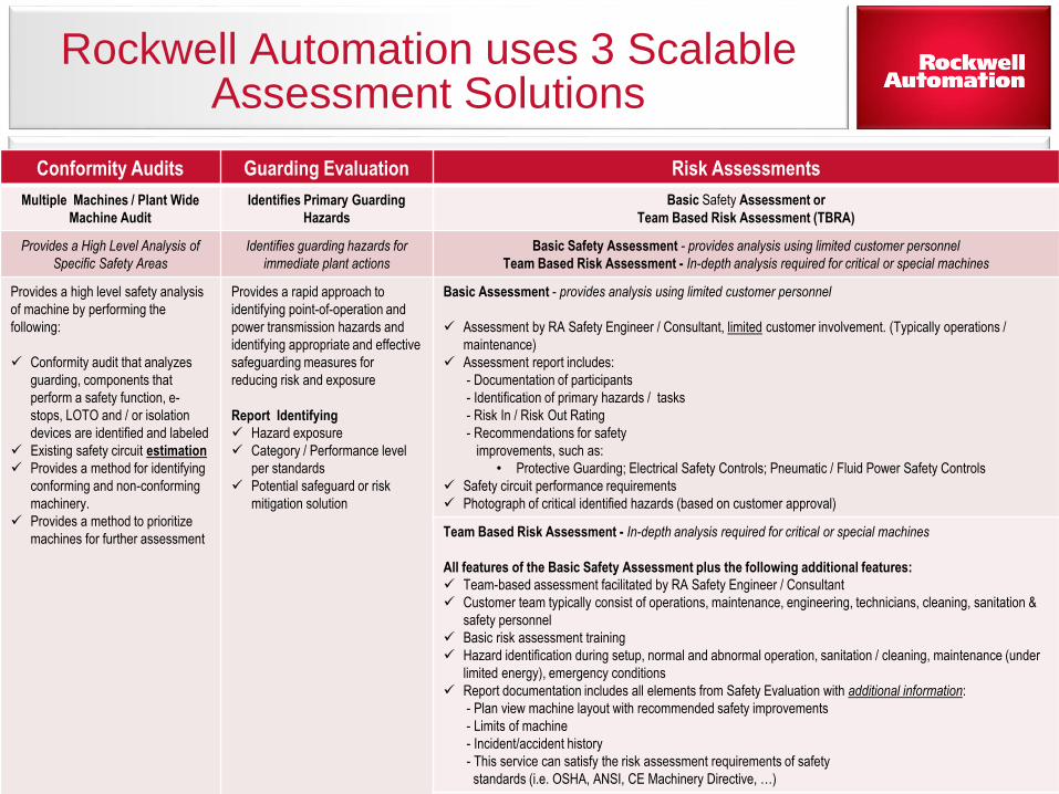
Rockwell Automation uses 3 Scalable Assessment Solutions
Copyri
ght ©
11Conformity Audits Guarding Evaluation Risk Assessments
Multiple Machines / Plant Wide
Machine Audit
Identifies Primary Guarding
Hazards
Basic Safety Assessment or
Team Based Risk Assessment (TBRA)
Provides a High Level Analysis of
Specific Safety Areas
Identifies guarding hazards for
immediate plant actions
Basic Safety Assessment - provides analysis using limited customer personnel
Team Based Risk Assessment - In-depth analysis required for critical or special machines
Provides a high level safety analysis
of machine by performing the
following:
Conformity audit that analyzes
guarding, components that
perform a safety function, e-
stops, LOTO and / or isolation
devices are identified and labeled
Existing safety circuit estimation
Provides a method for identifying
conforming and non-conforming
machinery.
Provides a method to prioritize
machines for further assessment
Provides a rapid approach to
identifying point-of-operation and
power transmission hazards and
identifying appropriate and effective
safeguarding measures for
reducing risk and exposure
Report Identifying
Hazard exposure
Category / Performance level
per standards
Potential safeguard or risk
mitigation solution
Basic Assessment - provides analysis using limited customer personnel
Assessment by RA Safety Engineer / Consultant, limited customer involvement. (Typically operations /
maintenance)
Assessment report includes:
- Documentation of participants
- Identification of primary hazards / tasks
- Risk In / Risk Out Rating
- Recommendations for safety
improvements, such as:
• Protective Guarding; Electrical Safety Controls; Pneumatic / Fluid Power Safety Controls
Safety circuit performance requirements
Photograph of critical identified hazards (based on customer approval)
Team Based Risk Assessment - In-depth analysis required for critical or special machines
All features of the Basic Safety Assessment plus the following additional features:
Team-based assessment facilitated by RA Safety Engineer / Consultant
Customer team typically consist of operations, maintenance, engineering, technicians, cleaning, sanitation &
safety personnel
Basic risk assessment training
Hazard identification during setup, normal and abnormal operation, sanitation / cleaning, maintenance (under
limited energy), emergency conditions
Report documentation includes all elements from Safety Evaluation with additional information:
- Plan view machine layout with recommended safety improvements
- Limits of machine
- Incident/accident history
- This service can satisfy the risk assessment requirements of safety
standards (i.e. OSHA, ANSI, CE Machinery Directive, …)

Copyright © 2013 Rockwell Automation, Inc. All Rights Reserved.Copyright © 2011 Rockwell Automation, Inc. All rights reserved. 12
5. Operate, Maintain & Improve
1. Assessment
4. Installation & Validation
2. Functional Requirements
3. Selection, Design & Verification
Step 2 in the Machinery Safety Lifecycle is the safety
requirements specification!
The SRS defines the functional requirements of the safety system!

Copyright © 2013 Rockwell Automation, Inc. All Rights Reserved.Copyright © 2011 Rockwell Automation, Inc. All rights reserved. 13
5. Operate, Maintain & Improve
1. Assessment
4. Installation & Validation
2. Functional Requirements
3. Selection, Design & Verification
Step 3 is the selection, design & design verification phase.
This step focuses on safety system design, product selection, circuit selection and design verification!

Copyright © 2013 Rockwell Automation, Inc. All Rights Reserved.
My assessment & requirements spec sure made this easy!
The design phase includes selection of mitigation techniques,
products, circuit designs & system structure determination!
Design considerations:• What mitigation technique should I use?• What products allow this functionality?• What circuit structure should I use?• What type of control system should I use?
(Relays/Controllers/PLC’s)• What type of special operations do I need?
(Zone control/Safe-speed/etc.)• Where are all of my safety devices?• What kind of interactions are needed for
auxiliary machines?• What kind of diagnostics do I need?• Should I use hardwiring or networked
systems?
The following slides are going to take a deeper look!

Copyright © 2013 Rockwell Automation, Inc. All Rights Reserved.Copyright © 2007 Rockwell Automation, Inc. All rights reserved.
15
Possible Mitigation Techniques!
Design it out
Fixed enclosing guard
Monitoring Access /
Interlocked Gates
Awareness Means, Training and Procedures
(Administrative)Personal protective
equipment
Most Effective
Least Effective
Hierarchy of Protective Measures
Copyright © 2013 Rockwell Automation, Inc. All Rights Reserved.
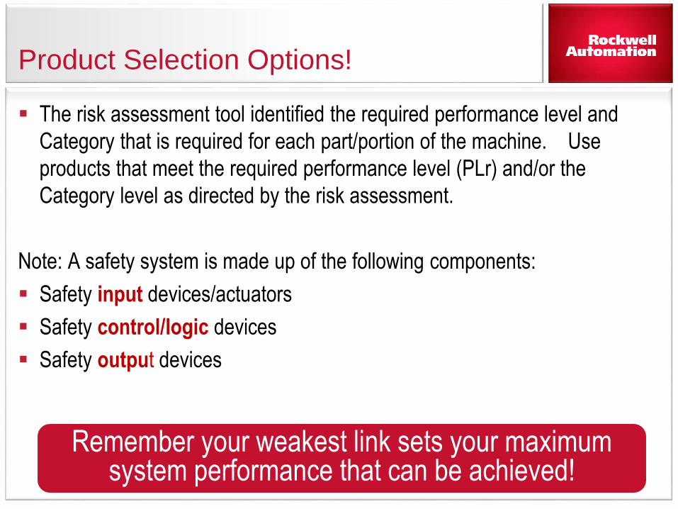
Product Selection Options!
The risk assessment tool identified the required performance level and
Category that is required for each part/portion of the machine. Use
products that meet the required performance level (PLr) and/or the
Category level as directed by the risk assessment.
Note: A safety system is made up of the following components:
Safety input devices/actuators
Safety control/logic devices
Safety output devices
Remember your weakest link sets your maximumsystem performance that can be achieved!

Copyright © 2013 Rockwell Automation, Inc. All Rights Reserved.
A complete safety solution is made up of combinations of input, logic and outputs!
Out complete portfolio is our key differentiator.
Glo
bal M
arket
Lead
ers
Light C
urtain
Laser Scan
ne
r
Cam
era
No
n-C
on
tact (RFID
)
Ke
y Inte
rlock
Ple
Lockin
g
Trap K
ey
Mats
Edge
s
Enab
ling
Two
-Han
d P
B
Cab
le P
ull
E-Stop
Re
lays
Co
nfigu
rable
PLC
DIO
Co
ntacto
rs
Drive
s
Servo
Mo
tion
Valve
s
Ind
icators
Info
rmatio
n le
vel
Co
mp
on
en
t leve
l
Cab
les &
Distr. B
locks
#1
Rockwell
#2
#3
#4
#5
Fully capable Offered but limited
No offering Offered through partner
Input Devices Logic Devices Output DevicesNetwork &
Connectivity

Copyright © 2013 Rockwell Automation, Inc. All Rights Reserved.
We also have the most Scalable Safety Logic Solutions in the market.
Integration Continuum
Offering solutions that fit your needs, not ours!
Basic Safety Solutions Modern Safety Solutions Contemporary Solutions
Low High
Simple connectivityMechanical linked machine
Stand alone machineLow cost
Just enough control
Multi-axis motionIncreased controller capabilities
Mix of mechanical and electrical controlsLow engineering costs
Coordinated multi-axis motionRobotic feeders
Electronic line shaftingAdvanced connectivity
Advanced information capabilities
1818Copyright © 2011 Rockwell Automation, Inc. All rights reserved.

Copyright © 2013 Rockwell Automation, Inc. All Rights Reserved.
Safety Relay/Safety Controller/Safety PLC Selection Matrix!
Safety Relays• 1 Zone• Local/Hardwired I/O• Simple Safety Logic• 1 to 2 dual channel Inputs• 2 to 3 outputs• Little to no motion
Safety Controllers & Expandable Relays• 1 to 3 Zones• Local & Distributed I/O• Simple & Complex Safety Logic• 1 to 10 dual channel Inputs• 1 to 10 outputs• Basic Diagnostics thru PLC• Up to 6 axes of motion
Safety PLCs• More Than 3 Zones• Distributed I/O• Semi-complex & Complex
Safety & Standard Logic• 1 to 100 dual channel Inputs• 1 to 100 outputs• Advanced HMI Diagnostics• Multiple axes of motion

Copyright © 2013 Rockwell Automation, Inc. All Rights Reserved.
Safety Output Selection Matrix
Safety Contactors & Relays• Simple on/off control• Power control• Signal control
Safety Variable Frequency Drives• On/off control with the ability
to control & monitor speed
Safety Servo Systems• On/off control• Speed control• Direction control• Position control• Location control• Acceleration control• Decceleration control

Copyright © 2013 Rockwell Automation, Inc. All Rights Reserved.
How do I verify my design!
The design phase also includes design verification!
Design verification considerations:• What is meant by system structure?• What is system reliability?• What is diagnostic coverage?• Where do I get the product safety data?• What verification tool should I use?

Copyright © 2013 Rockwell Automation, Inc. All Rights Reserved.
The 1st design Verification Consideration is
what types of structure are you going to use?
22Copyright © Rockwell Automation, Inc. All rights reserved.
CAT B/1 CAT 2
CAT 3 CAT 4 (higher diagnostic coverage that CAT 3)

Copyright © 2013 Rockwell Automation, Inc. All Rights Reserved.
The 2nd and 3rd steps of design verification includes
calculating the MTTFd and DC of the system.
23
MTTFd Mean Time to Dangerous FailureLow 0 -10 YearsMedium 10-30 YearsHigh 30-100 Years
DC Diagnostic Coverage = Detected Dangerous Failures / All Dangerous Failures
None DC < 60%Low 60 < DC < 90%Medium 90 < DC < 99%High DC >99%

Copyright © 2013 Rockwell Automation, Inc. All Rights Reserved. 24
a
b
c
d
ePer
form
ance
Lev
el
Designated
Architecture
Designated
Architecture
Designated
Architecture
Designated
Architecture
Designated
Architecture
Designated
Architecture
Designated
Architecture
Cat B Cat 1 Cat 2 Cat 2 Cat 3 Cat3 Cat 4
DC avg DC avg DC avg DC avg DC avg DC avg DC avg
<60% <60%
60% to <
90%
90% to <
99%
60% to <
90%
90% to <
99% 99%
Structure (Category)
Diagnostic Coverage (DC)
Reliability (MTTF)
Confirming PL is achieved by…Balancing Structure (Cat), Reliability (MTTFd)
and Diagnostic Coverage (DCavg)

Copyright © 2013 Rockwell Automation, Inc. All Rights Reserved.Copyright © 2011 Rockwell Automation, Inc. All rights reserved. 25
5. Operate, Maintain & Improve
1. Assessment
4. Installation & Validation
2. Functional Requirements
3. Selection, Design & Verification
The next phase includes validating that the safety
system operates as intended.
This step focuses on ensuring that the safety system was installed properly and that there is a defined process for validating system performance!

Copyright © 2013 Rockwell Automation, Inc. All Rights Reserved.Copyright © 2011 Rockwell Automation, Inc. All rights reserved. 26
5. Operate, Maintain & Improve
1. Assessment
4. Installation & Validation
2. Functional Requirements
3. Selection, Design & Verification
The final step covers Operation & maintenance to
ensure that the system remains functional
Step 5 focuses on ensuring that the safety system is operated properly and maintained to ensure continued effectiveness!

Copyright © 2013 Rockwell Automation, Inc. All Rights Reserved.Copyright © 2011 Rockwell Automation, Inc. All rights reserved. 27
5. Operate, Maintain & Improve
1. Assessment
4. Installation & Validation
2. Functional Requirements
3. Selection, Design & Verification
The Machinery Safety Lifecycle Never Ends!
The circle never ends. The system must be re-evaluated anytime modifications occur and each step must be followed!

Copyright © 2013 Rockwell Automation, Inc. All Rights Reserved.
Agenda
28
Closing & Wrap-up
Sample Project Utilizing the tools
Selection, Design, Verification, Development & Justification Tools
Safety Life-cycle Utilization
Safety System Development Process

Copyright © 2013 Rockwell Automation, Inc. All Rights Reserved.
Another way of doing Design Verification is using a software called SISTEMA
29
SISTEMA is a free design verification tool that isinternationally recognized!

Copyright © 2013 Rockwell Automation, Inc. All Rights Reserved.
Rockwell created a new safety selection tool that utilizes SISTEMA for verification
30
SAB utilizes SISTEMA for design verification but simplifies theprocess by using menus and questions to help with selection!

Copyright © 2013 Rockwell Automation, Inc. All Rights Reserved.
Rockwell Automation’s investment in tools!
Safety Return-On-Investment ToolFind out how to quantify the savings and productivity gains from safety investments. The Rockwell Automation Safety Return-On-Investment Tool accounts for improved safety, reduced claims, improved productivity, and other issues unique to safety applications.
Safety Functions
Safety Functions ProgramThe Safety Functions Program is building block approach to designing safety systems. Each building block has a complete documentation package that includes a description of each safety function, an electrical schematic, a bill of material, a SISTEMA verification calculation and a verification and validation plan.
SABSafety Automation BuilderThe Safety Automation Builder software package that allows users to import images of their machines. Users can identify hazardous access points and the associated hazards in order to develop a list of safety products that will be used to mitigate the risk. This gives the customer a complete drawing, a bill of material and SISTEMA calculation.
Safety Accelerator
Toolkit
Safety Accelerator Toolkit This toolkit provides easy to use system design, programming, and diagnostic tools to assist you in the rapid development and deployment of your safety systems using GuardLogix, Compact GuardLogix, or SmartGuard 600 Controllers, Guard I/O, and Safety Devices. The toolkit includes a risk assessment and system design guide, hardware selection guide, CAD drawings, safety logic routines, and operator status and diagnostic faceplates.
Connected Components
BB
Connected Components Building BlocksThese building blocks are tools that help customers develop safety solutions that utilize component class safety solutions. These building blocks include sample programs, electrical schematics and configuration document that help in the
ProSafeBuilder
ProSafe BuilderThe ProSafe Builder software gives users the ability to layout complete trapped key solutions for machinery safety applications with a tool that generate a bill of material and system configuration schematic/map.
The broadest suite of safety tools in the industry!

Copyright © 2013 Rockwell Automation, Inc. All Rights Reserved.
Safety System Development Tools
32
SABSafety Automation BuilderThe Safety Automation Builder software package that allows users to import images of their machines. Users can identify hazardous access points and the associated hazards in order to develop a list of safety products that will be used to mitigate the risk. This gives the customer a complete drawing, a bill of material and SISTEMA calculation.
ProSafeBuilder
ProSafe BuilderThe ProSafe Builder software gives users the ability to layout complete trapped key solutions for machinery safety applications with a tool that generate a bill of material and system configuration schematic/map.

Copyright © 2013 Rockwell Automation, Inc. All Rights Reserved.
What is Safety Automation Builder (SAB)?
SAB is a new tool designed to help develop complete safety system solutions. These solutions include conceptual layout drawings that includes zones, physical guards, hazards, access points and the products used to protect personnel.

Copyright © 2013 Rockwell Automation, Inc. All Rights Reserved.
Safety System Investment Justification Tool
34
Safety Return-On-Investment ToolFind out how to quantify the savings and productivity gains from safety investments. The Rockwell Automation Safety Return-On-Investment Tool accounts for improved safety, reduced claims, improved productivity, and other issues unique to safety applications.

Copyright © 2013 Rockwell Automation, Inc. All Rights Reserved.
ROI Example Output!
35
The Safety ROI tools helps customers justify safety projects based on
project cost and injury avoidance calculations!
Copyright © 2013 Rockwell Automation, Inc. All Rights Reserved.
Safety System Design Tools
36
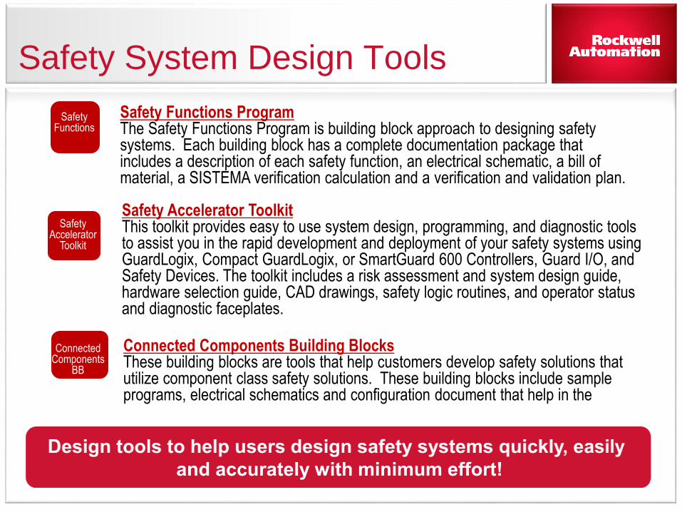
Safety Functions
Safety Functions ProgramThe Safety Functions Program is building block approach to designing safety systems. Each building block has a complete documentation package that includes a description of each safety function, an electrical schematic, a bill of material, a SISTEMA verification calculation and a verification and validation plan.
Safety Accelerator
Toolkit
Safety Accelerator Toolkit This toolkit provides easy to use system design, programming, and diagnostic tools to assist you in the rapid development and deployment of your safety systems using GuardLogix, Compact GuardLogix, or SmartGuard 600 Controllers, Guard I/O, and Safety Devices. The toolkit includes a risk assessment and system design guide, hardware selection guide, CAD drawings, safety logic routines, and operator status and diagnostic faceplates.
Connected Components
BB
Connected Components Building BlocksThese building blocks are tools that help customers develop safety solutions that utilize component class safety solutions. These building blocks include sample programs, electrical schematics and configuration document that help in the

Copyright © 2013 Rockwell Automation, Inc. All Rights Reserved.
Safety Functions are the building blocks of machinery safety solutions!
Risk Assessment Model & Confirm PLr
Determines (PLr) Confirms PLr Achieved

Copyright © 2013 Rockwell Automation, Inc. All Rights Reserved.
The more complicated the machine the mores safety functions you need!
E-Stop Device 1
E-Stop Device 2
Light Curtain 1
Door Interlock 1
Logic
Output 1
Output 2
Output 3
SF1
SF2
Logic
SF3
SF4 Output 4Logic
Logic
Large and complex machines may require multiple safety functions to provide a complete machine safety solution. Safety function documents are 1 way that Rockwell Automation can help!

Copyright © 2013 Rockwell Automation, Inc. All Rights Reserved. 39
Safety Function Documents
Safety Function: Emergency Stop Products: Light Curtain / GuardLogixSafety Rating: PLe, Cat. 4 to EN ISO 13849.1 2008
.
IntroductionImportant User InformationGeneral Safety InformationSafety Function RealizationSetup and WiringConfigurationProgrammingFalling Edge ResetCalculation of PFHdVerification and Validation PlanAdditional Resources

Copyright © 2013 Rockwell Automation, Inc. All Rights Reserved.
IA Safety Accelerator Toolkit
Development Tools and Quick Start Guide
Simplified Wiring
Preconfigured Logic
Quick Start Manual
Preconfigured HMI

Copyright © 2013 Rockwell Automation, Inc. All Rights Reserved.
Connected Component Building Blocks for Safety
41
Pre-designed Building Blocks with source code, drawings and quick-start guide to help you develop safety solutions!

Copyright © 2013 Rockwell Automation, Inc. All Rights Reserved.
Agenda
42
Closing & Wrap-up
Sample Project Utilizing the tools
Selection, Design, Verification, Development & Justification Tools
Safety Life-cycle Utilization
Safety System Development Process

Copyright © 2013 Rockwell Automation, Inc. All Rights Reserved.
Let’s look at a sample machine!
43
We are going to use the safety tools to develop a safety solution utilizing
Safety Automation Builder. This will leave us with a concept drawing, a
design verification and a complete bill of material.
We will use the ROI tool to help the customer justify the project.
We will then search for solutions for the selected products using safety
functions, safety accelerator toolkit and connected components building
blocks.

Copyright © 2013 Rockwell Automation, Inc. All Rights Reserved.
Machine Description
44
Infeed Conveyor
OutfeedConveyor
Rotary Table
Label P&P
Label Feeder
Hot Glue GunProduct

Copyright © 2013 Rockwell Automation, Inc. All Rights Reserved.
Step 1 – Risk Assessment
45
We are going to develop a risk assessment utilizing the ISO12100
evaluation method.
S1
S2
F2
F1
a
b
P1
P2
e
c
d
P1
P2P1
P2P1
P2
F2
F1
b
c
d

Copyright © 2013 Rockwell Automation, Inc. All Rights Reserved.
Step 1 Details
46
Normal operation
Maintenance
Set-up
Adjustment
Change-over
Start-up
Decommissioning
Etc.
Identify the hazards and associated risks! Develop a functional specification that outlines how each hazard needs to be protected for each mode of operation.
Thermal Hazard
Crushing Hazard
Pinching Hazard
Pinching Hazard
It is estimated that 60 to 70% of all injuries happen outside of normal production activities
yet most people spend 90% of their efforts around designing for production activities!

Copyright © 2013 Rockwell Automation, Inc. All Rights Reserved.
Step 2: Write a Functional Specification
47
The assessment defined the task and associated hazards and the required
system performance that is required.
The function specification will determine the required safety functions, their
design requirements and the type of functionality that is needed for each
mode of operation for each person that interacts with the machine.

Copyright © 2013 Rockwell Automation, Inc. All Rights Reserved.
Next Step Define Our Safety Functions
When Door Opens in zone #1,
tray packing stops, zone #2, tray
forming continues.
Safety Function:
Safety related stop function
initiated by a safe guard
Stopping hazardous
movement
Triggering Event:
Opening of guard door
Zone #1 Zone #2
Follow This Process for Every Safety Function in Every Machine Mode!

Copyright © 2013 Rockwell Automation, Inc. All Rights Reserved.
Step 3: Develop a safety project utilizing Safety Automation Builder.
49
This screen shot shows the layout drawing with identified hazard locations and access points that need to be protected!

Copyright © 2013 Rockwell Automation, Inc. All Rights Reserved.
Users can now start the safety selection process by selecting
input, logic and output devices for each identified safety need!
50
This screen shot shows the layout drawings with the selected safety devices!

Copyright © 2013 Rockwell Automation, Inc. All Rights Reserved.
Users can verify their design by exporting the SAB file to
SISTEMA for design verification! This is a sample report.
51
This screen shot shows the safety design verification report from SISTEMA!

Copyright © 2013 Rockwell Automation, Inc. All Rights Reserved.
Completed Bill of Material from ProposalWorks &SAB!
52
This screen shot shows the completed bill of material for the labeler machine safety system!

Copyright © 2013 Rockwell Automation, Inc. All Rights Reserved.
Now we have a price! We need to justify the investment!
53
We will use the Safety Return on Investment Tool to justify the project
based on projected reductions of injuries and productivity enhancements!
Let’s calculate our savings and ROI for this machine example!

Copyright © 2013 Rockwell Automation, Inc. All Rights Reserved.
The next step after selection, design verification & justification is design!
54
Now we need to start making schematics, developing programs and
configuration documents. We will guide you to locations that can help!
The Safety Functions documents are found on the safety resource center!

Copyright © 2013 Rockwell Automation, Inc. All Rights Reserved.
An additional tool that can help is Safety Accelerator Toolkit
55
Safety Accelerator Toolkit
The Safety Accelerator Toolkit can be found on the safety resource center or by asking your local Rockwell distributor!

Copyright © 2013 Rockwell Automation, Inc. All Rights Reserved.
An additional tool that can help is Connected
Component Building Blocks for Safety
56
The Safety Building Blocks can be found by asking your local Rockwell distributor for a CD!

Copyright © 2013 Rockwell Automation, Inc. All Rights Reserved.
Agenda
57
Closing & Wrap-up
Sample Project Utilizing the tools
Selection, Design, Verification, Development & Justification Tools
Safety Life-cycle Utilization
Safety System Development Process

Copyright © 2013 Rockwell Automation, Inc. All Rights Reserved.
Rockwell Automation the global leader in safety (Services/Products/Solutions)!
Best in class assessment services to help you to determine
safety system needs!
Safety Design Tools and resources to help engineers and
designers with safety system development.
Products selection and design verification tools to helps
engineers select product quickly and accurately.
Installation and start-up services to help meet productivity and
start-up needs.
Validation services to ensure that the safety system operates
as designed and constructed.
Preventive maintenance development services to ensure the
safety system continues to operate properly.

Copyright © 2013 Rockwell Automation, Inc. All Rights Reserved.Copyright © 2013 Rockwell Automation, Inc. All Rights Reserved.Rev 5058-CO900D
Questions?