T5e Operator Manual - Tennant Co · 2020-02-12 · 1. Do not operate machine: - Unless trained and...
41
T5e 9002337 Rev. 06 (10-2015) Walk-Behind Scrubber *9002337* North America / International English EN Operator Manual For the latest Parts manuals and other language Operator manuals, visit: www.tennantco.com/manuals The Safe Scrubbing Alternative TennantTrue Parts IRIS a Tennant Technology
Transcript of T5e Operator Manual - Tennant Co · 2020-02-12 · 1. Do not operate machine: - Unless trained and...

T5e
9002337Rev. 06 (10-2015)
Walk-Behind Scrubber
*9002337*
North America / International
English EN
Operator Manual
For the latest Parts manuals and otherlanguage Operator manuals, visit:
www.tennantco.com/manuals
The Safe Scrubbing Alternative
TennantTrue PartsIRIS a Tennant Technology

OPERATION
2 Tennant T5e (10- 15)
This manual is furnished with each new model.It provides necessary operation and maintenanceinstructions.
Read this manual completely and understand themachine before operating or servicing it.
This machine will provide excellent service. However,the best results will be obtained at minimum costs if:
S The machine is operated with reasonable care.
S The machine is maintained regularly - per themachine maintenance instructions provided.
S The machine is maintained with manufacturersupplied or equivalent parts.
PROTECT THE ENVIRONMENTPlease dispose of packaging materials,old machine components such as batter-ies, hazardous fluids, including anti-freeze and oil, in an environmentallysafe way according to local waste dis-posal regulations.
Always remember to recycle.
TENNANT CompanyPO Box 1452Minneapolis, MN 55440Phone: (800) 553- 8033 or (763) 513- 2850
www.tennantco.com
Tennant Cleaning Systems & Equipment Co., LtdBuilding 1, No. 3777 Caoying RoadQingpu Shanghai, China 201712电话 Phone: 86 21 6922 5333传真 Fax: 86 21 69225151www.tennantco.com.cn
FaSK- PAK and Insta-Fit are US registered and unregistered trademarks ofTennant Company.
Specifications and parts are subject to change without notice.
Copyright E 2006- 2015 TENNANT COMPANY
All rights reserved.
INTENDED USE
The T5e walk-behind scrubber is designed to scrubhard surfaces (concrete, asphalt, stone, synthetic, etc)in an indoor environment. Typical applications includehotels, schools, hospitals, factories, shops, offices, andrental businesses. Do not use this machine oncarpeted surfaces. Use only recommended pads andcommercially available floor cleaners intended formachine application. Do not use this machine otherthan described in this Operator Manual.
MACHINE DATA
Please fill out at time of installationfor future reference.
Model No. -
Serial No. -
Installation Date -

OPERATION
Tennant T5e (10- 15) 3
TABLE OF CONTENTS
IMMPORTANT SAFETY INSTRUCTIONS 4. . . . . .
SAFETY LABELS 6. . . . . . . . . . . . . . . . . . . . . . . . . . .
MACHINE COMPONENTS 7. . . . . . . . . . . . . . . . . . .
CONTROL PANEL COMPONENTS 8. . . . . . . . . . .
MACHINE INSTALLATION 9. . . . . . . . . . . . . . . . . . .UNCRATING MACHINE 9. . . . . . . . . . . . . . . . . .INSTALLING BATTERIES 9. . . . . . . . . . . . . . . .
HOW THE MACHINE WORKS 10. . . . . . . . . . . . . . .
BRUSH AND PAD INFORMATION 10. . . . . . . . . . . .
MACHINE SETUP 10. . . . . . . . . . . . . . . . . . . . . . . . . .ATTACHING SQUEEGEE ASSEMBLY 10. . . . .INSTALLING BRUSHES/PADS 11. . . . . . . . . . . .ec-H2O NanoClean WATER CONDITIONINGCARTRIDGE (ec-H2O NanoClean model) 12. .INSTALLING FaST- PAK CARTON(FaST Model) 13. . . . . . . . . . . . . . . . . . . . . . . . . . .FILLING SOLUTION TANK 13. . . . . . . . . . . . . . .ADJUSTING CONTROL CONSOLE HEIGHT 13
MACHINE OPERATION 14. . . . . . . . . . . . . . . . . . . . .PRE-OPERATION CHECKS 14. . . . . . . . . . . . . .STARTING THE MACHINE 14. . . . . . . . . . . . . . .EMERGENCY STOPPING 16. . . . . . . . . . . . . . . .WHILE OPERATING MACHINE 16. . . . . . . . . . .BATTERY METER 17. . . . . . . . . . . . . . . . . . . . . . .HOUR METER 17. . . . . . . . . . . . . . . . . . . . . . . . . .CIRCUIT BREAKERS / FUSES 17. . . . . . . . . . . .OFF- AISLE WAND SETUPAND OPERATION 18. . . . . . . . . . . . . . . . . . . . . .PREPARING MACHINE FOR OFF- AISLE WANDSCRUBBING: 18. . . . . . . . . . . . . . . . . . . . . . . . . .OPERATING THE OFF- AISLE WAND: 18. . . . .
DRAINING AND CLEANING TANKS 19. . . . . . . . . .DRAINING RECOVERY TANK 19. . . . . . . . . . . .DRAINING SOLUTION TANK 19. . . . . . . . . . . . .
CHARGING BATTERIES 20. . . . . . . . . . . . . . . . . . . .BATTERY CHARGER SPECIFICATIONS 20. . .ON- BOARD BATTERY CHARGERSETTINGS 20. . . . . . . . . . . . . . . . . . . . . . . . . . . . .USING THE ON- BOARD BATTERY CHARGER(220- 240V Chargers) 21. . . . . . . . . . . . . . . . . . . .USING THE ON- BOARD BATTERY CHARGER(120V Chargers) 21. . . . . . . . . . . . . . . . . . . . . . . .ON- BOARD BATTERY CHARGER ERRORCODES 23. . . . . . . . . . . . . . . . . . . . . . . . . . . . . . . .USING AN OFF- BOARD BATTERYCHARGER 23. . . . . . . . . . . . . . . . . . . . . . . . . . . . .
ADJUSTING SCRUB HEAD BRUSHES 24. . . . . . .DISK MODEL 24. . . . . . . . . . . . . . . . . . . . . . . . . . .CYLINDRICAL BRUSH MODEL 25. . . . . . . . . . .
MACHINE MAINTENANCE 27. . . . . . . . . . . . . . . . . .DAILY MAINTENANCE 27. . . . . . . . . . . . . . . . . . .MONTHLY MAINTENANCE 29. . . . . . . . . . . . . . .BATTERY MAINTENANCE 30. . . . . . . . . . . . . . .SQUEEGEE BLADES 31. . . . . . . . . . . . . . . . . . . .MOTOR MAINTENANCE 31. . . . . . . . . . . . . . . . .FaST SYSTEM MAINTENANCE 32. . . . . . . . . . .ec-H2O NanoClean WATER CONDITIONINGCARTRIDGE REPLACEMENT 32. . . . . . . . . . . .ec-H2O MODULE FLUSH PROCEDURE 33. . .
JACKING UP MACHINE 34. . . . . . . . . . . . . . . . . . . . .
TRANSPORTING MACHINE 34. . . . . . . . . . . . . . . . .
STORING MACHINE 34. . . . . . . . . . . . . . . . . . . . . . . .FREEZE PROTECTION 35. . . . . . . . . . . . . . . . . .
TROUBLESHOOTING 37. . . . . . . . . . . . . . . . . . . . . . .
BATTERY METER LED FAULT CODES 39. . . . . . .
MACHINE SPECIFICATIONS 40. . . . . . . . . . . . . . . .
MACHINE DIMENSIONS 41. . . . . . . . . . . . . . . . . . . .

OPERATION
4 Tennant T5e (10- 15)
IMPORTANT SAFETY INSTRUCTIONS - SAVE THESE INSTRUCTIONS
The following warning precautions are used throughoutthis manual as indicated in their description:
WARNING: To warn of hazards or unsafepractices which could result in severe personalinjury or death.
FOR SAFETY: To identify actions which must befollowed for safe operation of equipment.
The following information signals potentiallydangerous conditions to the operator. Know whenthese conditions can exist. Locate all safety devices onthe machine. Report machine damage or faultyoperation immediately.
WARNING: Fire Or Explosion Hazard
- Never Use Flammable Liquids Or OperateMachine In Or Near Flammable Liquids, VaporsOr Combustible Dusts.
This machine is not equipped with explosion proofmotors. The electric motors will spark upon startup and during operation which could cause a flashfire or explosion if machine is used in an areawhere flammable vapors/liquids or combustibledusts are present.
- Do Not Pick Up Flammable Materials OrReactive Metals.
- Batteries Emit Hydrogen Gas. Keep Sparks AndOpen Flame Away. Keep Battery CompartmentOpen When Charging.
WARNING: Electrical Hazard
- Disconnect Battery Cables and Charger PlugBefore Servicing Machine.
- Do Not Charge Batteries with Damaged PowerSupply Cord. Do Not Modify Plug.
If the charger supply cord is damaged or broken, itmust be replaced by the manufacturer or itsservice agent or a similarly qualified person inorder to avoid a hazard.
WARNING: Spinning Brush. Keep HandsAway. Turn Off Power Before Working On Machine.
This machine may be equipped with technologythat automatically communicates over the cellularnetwork. If the machine will be operated where cellphone use is restricted because of concernsrelated to equipment interference, please contact aTennant representative for information on how todisable the cellular communication functionality.
WARNING: This machine contains chemicalsknown to the state of California to cause cancer,birth defects, or other reproductive harm.
FOR SAFETY:
1. Do not operate machine:- Unless trained and authorized.- Unless operator manual is read and
understood.- Under the influence of alcohol or drugs.- While using cell phone or other electronic
devices.- Unless mentally and physically capable of
following machine instructions.- If not in proper operating condition.- In areas where flammable vapors/liquids or
combustible dusts are present.- In areas that are too dark to safely see the
controls or operate the machine.- In areas with possible falling objects.- With pads or accessories not supplied or
approved by Tennant. The use of otherpads may impair safety.
- In outdoors areas. This machine is forindoor use only.
2. Before starting machine:- Check machine for fluid leaks.- Make sure all safety devices are in place
and operate properly.
3. When using machine:- Use only as described in this manual.- Go slowly on inclines and slippery
surfaces.- Wear closed- toe non- slip shoes.- Reduce speed when turning.- Use care when reversing machine.- Do not carry passengers on machine.- Keep children and unauthorized persons
away from machine.- Do not allow machine to be used as a toy.- Always follow safety and traffic rules.- Report machine damage or faulty operation
immediately.- Follow mixing and handling instructions on
chemical containers.- Follow site safety guidelines concerning
wet floors.- Do not scrub on inclines that exceed 5%
grade or transport on inclines that exceed8%.

OPERATION
Tennant T5e (10- 15) 5
4. Before leaving or servicing machine:- Stop on level surface.- Set parking brake, if equipped.- Turn off machine and remove key.
5. When servicing machine:- All work must be done with sufficient
lighting and visibility.- Keep work area well ventilated.- Avoid moving parts. Do not wear loose
clothing, jewelry and secure long hair.- Block machine tires before jacking machine
up.- Jack machine up at designed locations
only. Support machine with jack stands.- Use hoist or jack that will support the
weight of the machine.- Do not power spray or hose off machine.- Disconnect battery connections and battery
charger before working on machine.- Keep all metal objects off batteries.- The use of incompatible battery chargers
may damage battery packs and potentiallycause a fire hazard.
- Inspect charger cord regularly for damage.- Do not disconnect the charger DC cord
from the machine receptacle when chargeris operating. Arcing may result. If thecharger must be interrupted duringcharging, disconnect the AC power supplycord first.
- Avoid contact with battery acid.- Use a hoist or adequate assistance when
lifting batteries.- All repairs must be performed by trained
personnel.- Do not modify the machine from its original
design.- Use Tennant supplied or approved
replacement parts.- Wear personal protective equipment as
needed and where recommended in thismanual.
For Safety: wear protective gloves.
For Safety: wear eye protection.
6. When loading/unloading machine onto/offtruck or trailer:- Drain tanks before loading machine.- Lower scrub head and squeegee before
tying down machine.- Turn off machine and remove key.- Use a ramp, truck or trailer that will support
the weight of the machine and operator.- Use a winch if ramp incline exceeds a
19.5% grade level.- Set parking brake, if equipped.- Block machine wheels.- Use tie- down straps to secure machine.

OPERATION
6 Tennant T5e (10- 15)
SAFETY LABELS
The safety labels appear on the machine in the locations indicated. Replace labels if they are missing or becomedamaged or illegible.
WARNING LABEL - Located on recovery tank cover.
BATTERY CHARGE LABEL -Located on bottom side of recovery tank.
WARNING: Fire Or ExplosionHazard. Batteries Emit HydrogenGas. Keep Sparks And OpenFlame Away. Keep BatteryCompartment Open WhenCharging.
SPINNING BRUSH LABEL -Located on scrub head
WARNING: Spinning Brush.Keep Hands Away. Turn Off PowerBefore Working On Machine.

OPERATION
Tennant T5e (09- 08) 7
MACHINE COMPONENTS
1
2
8
6
5
10
4
13
25
1415
16
20
17
18
23
27
22
12
7
11
19
21
3
9
26
24
28
ec-H2O Model
1. Adjustable Control Console2. Control Panel3. Emergency Stop Button (option)4. Recovery Tank Drain Hose5. On- board Battery Charger6. Squeegee Lift Lever7. Solution Flow Control Knob8. Squeegee Vacuum Hose9. Squeegee Assembly10. Wall Rollers11. Solution Tank Level/Drain Hose12. Rear Fill Port13. Recovery Tank Support Stand14. Circuit Breaker Panel
15. FaST- PAK Carton Compartment (FaST Model)ec-H2O System Module (ec-H2O Model)
16. Batteries17. Off- Aisle Wand Solution Hose Coupler18. Recovery Tank19. Recovery Tank Cover20. Cup Holders21. Solution Tank22. Front Fill Port23. Disk Scrub Head24. Pad Release Plunger25. Pad Driver Window26. Scrub Head Skirt27. Parking Brake (option)28. Cylindrical Brush Scrub Head

OPERATION
8 Tennant T5e (09- 08)
CONTROL PANEL COMPONENTS
6
7
8
9 12
1 4
2
3 3
11
5
9
10
ec-H2O Model
ec-H2O Model
1. Battery Meter2. Reverse Trigger3. Start Triggers4. Brush Pressure Meter5. Control Console Height Adjustment Lever6. Speed Control Knob
7. Brush Pressure Switch8. Off- Aisle Wand on/off Switch (option)9. FaST system on/off switch (FaST Model)
ec-H2O system on/off switch (ec-H2O Model)10. ec-H2O system indicator light (ec-H2O Model)11. Main Power on/off Key Switch12. Hour Meter
OPERATION
Tennant T5e (10- 15) 9
MACHINE INSTALLATION
UNCRATING MACHINE
1. Carefully check the shipping crate for signs ofdamage. Report damage at once to carrier.
2. Check the contents list. Contact distributor formissing items.Contents:S 4- 6 V Batteries- OptionalS 3- Battery Cable JumpersS Battery TrayS 1- FaST- PAK 365 Concentrate- (FaST Model)S Squeegee AssemblyS 2- Pad drivers (Disk Model)S 2- Brushes (Cylindrical Brush Model)
3. To uncrate your machine, remove the shippinghardware and straps that secure the machine tothe pallet. Carefully back machine down ramp.
ATTENTION: Do not roll machine off pallet unless aramp is used, machine damage may occur.
ATTENTION: To prevent possible machine damage,install batteries after removing machine fromshipping pallet.
INSTALLING BATTERIES
WARNING: Batteries emit hydrogen gas.Explosion or fire can result. Keep sparks and openflame away. Keep battery compartment open whencharging.
FOR SAFETY: When servicing machine, wearpersonal protection equipment as needed. Avoidcontact with battery acid.
Battery Specifications:Four 6 volt, 235A/20h deep cycle batteries. Maximumbattery dimensions:7.5 in/190 mm W x 10.8 in/275 mm L x 11 in/284 mmH.
1. Park the machine on a level surface, remove thekey and set the parking brake, if equipped.
FOR SAFETY: Before leaving or servicing machine,stop on level surface, set parking brake ifequipped, turn off machine and remove key.
2. Carefully install the batteries into the batterycompartment tray (Figure 1). Arrange the batteryposts as shown (Figure 2).
FIG. 1
3. Connect the battery cables to the battery posts asshown (Figure 2), RED TO POSITIVE (+) andBLACK TO NEGATIVE (- ).
235 A/20Ah
MachineFront
RED
BLACK
FIG. 2
IMPORTANT: If your machine is equipped with theon- board battery charger, make sure that thecharger is properly set for your battery type beforecharging (See ON-BOARD CHARGER SETTINGS).

OPERATION
10 Tennant T5e (10- 15)
HOW THE MACHINE WORKS
Conventional Scrubbing:Water and detergent from the solution tank flow to thefloor through a solution valve. The brushes use thedetergent and water to scrub the floor clean. As themachine moves forward, the squeegee wipes the dirtysolution from the floor into the recovery tank.
ec-H2O NanoClean Scrubbing (ec-H2O Model):When using the ec-H2O NanoClean technology, normalwater passes through a module where it is electricallyconverted into a cleaning solution. The electricallyconverted water attacks the dirt, allowing the machineto easily scrub away the suspended soil. The convertedwater then returns to normal water in the recovery tank.
Foam Scrubbing (FaST Model):(FaST- Foam activated Scrubbing Technology)Unlike conventional scrubbing, the FaST system injectsthe FaST- PAK concentrate formula with a smallamount of water and air onto the floor. The mixturecreates a large volume of expanded wet foam for thebrush to scrub the floor clean. As the machine movesforward, the foam collapses and the squeegeerecovers the dirty solution into the recovery tankleaving the floor clean, dry and slip free.
BRUSH AND PAD INFORMATION
For best cleaning results use the appropriate brushtype for your cleaning application. Refer to the Partsmanual for part number information.
Polypropylene Bristle Scrub Brush (Black) -This general purpose polypropylene bristle scrub brushis used for scrubbing lightly compacted soilage. Thisbrush works well for maintaining concrete, wood andgrouted tile floors.
Soft Nylon Bristle Scrub Brush (White) -Recommended for cleaning coated floors withoutremoving finish. Cleans without scuffing.
Super Abrasive Bristle Scrub Brush (Gray) -Nylon fiber impregnated with abrasive grit to removestains and soilage. Strong action on any surface.Performs well on buildup, grease, or tire marks.
Polishing Pad (White) -Used to maintain highly polished or burnished floors.
Buffing Pad (Red) - Used for light duty scrubbingwithout removing floor finish.
Scrubbing Pad (Blue) - Used for medium toheavy- duty scrubbing. Removes dirt, spills, and scuffsand leaves surface clean and ready for recoating.
Stripping Pad (Brown) - Used for stripping of floorfinish to prepare the floor for recoating.
Heavy Duty Stripping Pad (Black) - Used foraggressive stripping of heavy finishes/sealers, or veryheavy duty scrubbing.
MACHINE SETUP
ATTACHING SQUEEGEE ASSEMBLY
FOR SAFETY: Before leaving or servicing machine,stop on level surface, set parking brake ifequipped, turn off machine and remove key.
1. Park the machine on a level surface, remove thekey and set the parking brake if equipped.
2. Lift the squeegee lift lever to the upward position(Figure 3).
FIG. 3
3. Mount the squeegee assembly to the squeegeepivot bracket and secure with knobs (Figure 4).
FIG. 4

OPERATION
Tennant T5e (10- 15) 11
4. Connect the vacuum hose to the squeegeeassembly. Loop the hose as shown using the hoseclip provided (Figure 5).
FIG. 5
5. Check the squeegee blades for proper deflection.The blades should deflect as shown (Figure 6).
FIG. 6
6. To adjust the blade deflection, place the squeegeeassembly on a level surface and adjust the castersas shown (Figure 7).
2 mm
FIG. 7
INSTALLING BRUSHES/PADS
FOR SAFETY: Before leaving or servicing machine,stop on level surface, set parking brake ifequipped, turn off machine and remove key.
Disk Model:
1. Raise scrub head off the floor and remove key.
2. Attach the pad to the pad driver before installingthe driver. Secure pad with centerlock (Figure 8).
FIG. 8
3. Set the yellow spring clips to the open position tomake brush installation easier. Press clips downand outward to set (Figure 9).
FIG. 94. Align the pad driver or brush under the motor hub
and push it upward to engage hub (Figure 10).
FIG. 10

OPERATION
12 Tennant T5e (10- 15)
5. To remove the pad driver or brush, raise the scrubhead and push the pad release plunger downward(Figure 11).
FIG. 11
6. Check the scrub head to ensure that it is properlyadjusted (See ADJUSTING SCRUB HEADBRUSHES).
Cylindrical Brush Model:
1. Raise scrub head off the floor and remove key.
2. Remove idler plate from scrub head by pressingthe spring tab downward (Figure 12).
FIG. 12
3. Attach idler plate to the brush end that has thedouble row of bristles (Figure 13). Install brush.
Double row ofbristles
FIG. 13
4. Check the brushes to ensure they are properlyadjusted (See ADJUSTING SCRUB HEADBRUSHES).
ec-H2O NanoClean WATER CONDITIONINGCARTRIDGE (ec-H2O NanoClean model)
(ec-H2O models labeled ec-H2O NanoClean)
The ec-H2O system is equipped with a waterconditioning cartridge. The cartridge is designed toprotect the machine’s plumbing system from potentialscaling. The cartridge is located behind the right sidebrush motor (Figure 14).
The cartridge is required to be replaced when it reachesits maximum water usage or expiration time of when thecartridge was activated, which ever comes first.
Depending on machine usage a new cartridge can lastanywhere from 12 to 24 months.
FIG. 14
All cartridges are labeled with a manufacture date. Theshelf-life of an un-installed cartridge is one year frommanufacture date. For new cartridge replacement, theecH2O module timer must be reset. See ec-H2ONanoClean WATER CONDITIONING CARTRIDGEREPLACEMENT.
ATTENTION: During first time use and after replacingthe water conditioning cartridge, the ec-H2O systemwill automatically override the selected solution flowrate for up to 75 minutes.The ec-H2O system indicator light will blink green/redwhen it’s time to replace cartridge (Figure 15).
FIG. 15

OPERATION
Tennant T5e (10- 15) 13
INSTALLING FaST-PAK CARTON (FaST Model)
ATTENTION: The FaST-PAK Concentrate Formulais specifically designed for the FaST system.NEVER use a substitute. Machine damage mayresult.
1. Pull out the hose connector from the FaST- PAKcarton and remove cap (Figure 16).
FIG. 16
2. Open the battery compartment. Connect theFaST- PAK carton to the supply hose and placecarton in compartment (Figure 17). Make sure thehose does not get pinched.
FIG. 17
3. When the supply hose is not in use, connect thestorage plug to prevent the FaST system fromdrying out and clogging up the hose. (Figure 18).
FIG. 18
FILLING SOLUTION TANK
FOR SAFETY: Before leaving or servicing machine,stop on level surface, set parking brake ifequipped, turn off machine and remove key.
Using a hose or bucket, fill the solution tank to the“MAX 85L” mark (Figure 19).
For Conventional Scrubbing: Use hot water(140F/60C maximum). Pour a recommendedcleaning detergent into the solution tank according tomixing instructions on the container.
For FaST or ec-H2O Scrubbing: Use cool cleanwater only (less than 70F/21C). Do not add anyconventional floor cleaning detergents, system failuremay result.
FIG. 19
ATTENTION: For Conventional Scrubbing, only usecommercially approved cleaning detergents.Machine damage due to improper detergent usagewill void the manufacturer’s warranty.
WARNING: Flammable materials can cause anexplosion or fire. Do not use flammable materialsin tank(s).
ADJUSTING CONTROL CONSOLE HEIGHT
Pull the control console height adjustment lever and liftor lower the console to a comfortable operating height.Release lever to lock in position (Figure 20).
FIG. 20
OPERATION
14 Tennant T5e (03- 15)
MACHINE OPERATION
FOR SAFETY: Do not operate machine, unlessoperator manual is read and understood.
PRE-OPERATION CHECKS
- Sweep area.
- Check the battery meter.
- Check the brushes/pads for wear.
- Check the squeegee blades for wear and properadjustment.
- Make sure the recovery tank is empty and the floatshut- off screen is installed and clean.
- Check the scrub head skirt for wear.
- For FaST Scrubbing: Check the FaST- PAKconcentrate level.
- For FaST or ec-H2O Scrubbing: Make sure thesolution tank is filled with cool clean water only.
- For FaST or ec-H2O Scrubbing: Ensure that allconventional cleaning agents are drained andrinsed from solution tank.
STARTING THE MACHINE
1. Release the parking brake if equipped (Figure 21).
2. Turn the key to the on ( I ) position (Figure 21).
FIG. 21
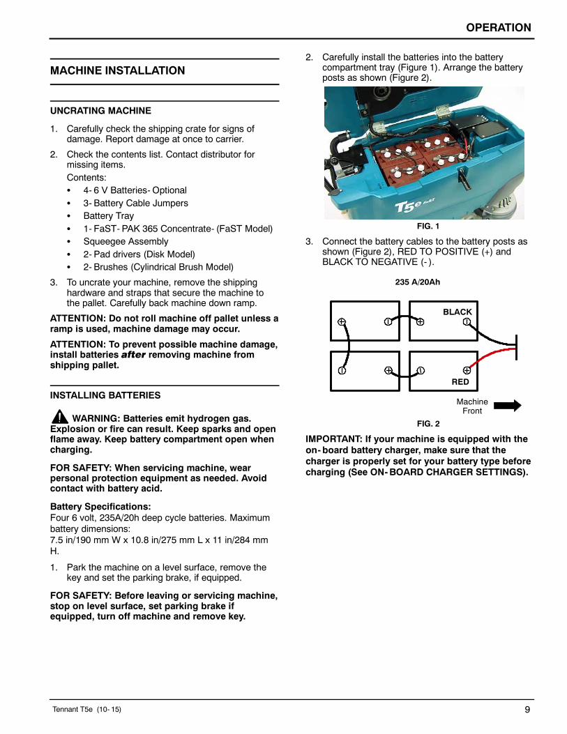
3. FaST model: Press the FaST system switch to theon ( I ) position (Figure 22).
ec-H2O model: Press the ec-H2O system switchto the on ( I ) position (Figure 22). The ec-H2Osystem indicator light will not turn on until themachine starts scrubbing.
ATTENTION: ec-H2O NanoClean models - During firsttime use and after replacing the water conditioningcartridge, the ec-H2O system will automaticallyoverride the selected solution flow rate for up to 75minutes.
FIG. 22
IMPORTANT: NEVER turn the FaST/ec-H2O systemswitch on when conventional scrubbing. Conventionalcleaning detergents/restorers may cause failure to theFaST/ec-H2O solution system. Drain, rinse and refillsolution tank with cool clean water before operating theFaST/ec-H2O system.
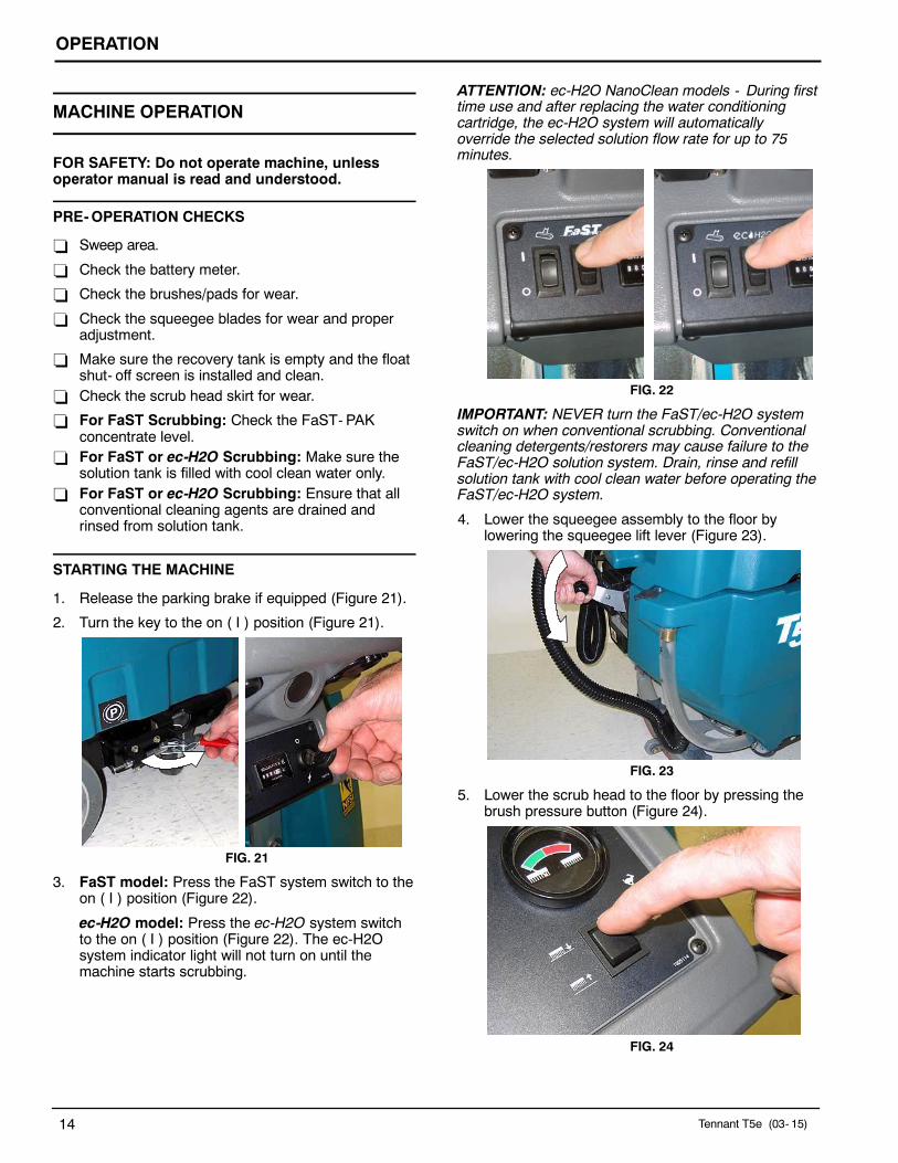
4. Lower the squeegee assembly to the floor bylowering the squeegee lift lever (Figure 23).
FIG. 23
5. Lower the scrub head to the floor by pressing thebrush pressure button (Figure 24).
FIG. 24

OPERATION
Tennant T5e (03- 15) 15
6. Pull the triggers to begin scrubbing (Figure 25). Toreverse the machine, simply pull the reversetrigger. Raise squeegee when reversing machine.
FIG. 25
7. Adjust the speed control knob to a desiredscrubbing speed (Figure 26).
NOTE: 45- 60 meters per minute is the recommendedscrubbing speed.
FIG. 26
8. Check the brush pressure meter reading and adjustthe pressure if needed (Figure 27). Do not operatethe machine in the red zone, floor damage or brushmotor overload may result.
FIG. 27
9. For conventional scrubbing, adjust the solution flowcontrol knob to a desired flow rate (Figure 28).
NOTE: The solution flow cannot be adjusted when themachine is set for FaST scrubbing or for ec-H2Oscrubbing on ec-H2O models manufactured beforeec-H2O NanoClean models.
FIG. 28
ec-H2O NanoClean Models(ec-H2O models labeled ec-H2O NanoClean)
To adjust the solution flow rate when ec-H2Oscrubbing, press the solution flow button located onthe ec-H2O module (Figure 29). One LED= low,two LED’s=medium, and three LED’s= high (Figure29). The ec-H2O module is located under therecovery tank. Drain recovery tank before liftingtank.
FIG. 29
10. To stop scrubbing, release the triggers, raise thescrub head and squeegee and turn the key to theoff position.

OPERATION
16 Tennant T5e (03- 15)
EMERGENCY STOPPING
Strike the emergency stop button, if equipped, in theevent of an emergency (Figure 30). This button shutsoff all power to machine. To regain power, turn thebutton clockwise.
FIG. 30
WHILE OPERATING MACHINE
WARNING: Flammable materials or reactivemetals can cause an explosion or fire. Do notpickup.
1. Overlap each scrub path by 2 in/5 cm.
2. Keep the machine moving to prevent damage tofloor finish.
3. Do not operate the machine on inclines that exceed
5%.
4. Conventional scrubbing: Pour a commerciallyapproved foam control solution into the recoverytank if excessive foam appears.
ATTENTION: Do not allow foam to enter the floatshut-off screen located in the recovery tank,vacuum motor damage will result. Foam will notactivate the float shut-off screen.
5. For heavily soiled areas, use the double scrubbingmethod. First scrub the area with the squeegee up,let solution set for 3- 5 minutes, then scrub the areaa second time with squeegee down.
6. When leaving the machine unattended, remove thekey and set the parking brake, if equipped.
7. If the machine detects a fault, the battery meter willblink a fault code (See BATTERY METER LEDFAULT CODES).
8. ec-H2O NanoClean Models(ec-H2O models labeled ec-H2O NanoClean)
If the ec-H2O system indicator light begins to blinkgreen/red, the water conditioning cartridge needsto be replaced (Figure 31). See ec-H2ONanoClean WATER CONDITIONING CARTRIDGEREPLACEMENT.
FIG. 31
ec-H2O SYSTEMINDICATOR LIGHT CODE CONDITION
Solid green Normal operation
Blinking green/red Water conditioningcartridge expired.Replace cartridge.
Solid or blinking* red Contact Service Center
*Verify if cleaning detergent was added to solution tank.If ec-H2O system was operated with cleaningdetergent, drain solution tank, add clear water andoperate the ec-H2O system until the indicator lightcode clears.
ec-H2O Models(ec-H2O models manufactured before ec-H2ONanoClean models)
If an alarm sounds and the ec-H2O system indicatorlight begins to blink red, the ec-H2O module must beflushed to resume ec-H2O operation (See ec-H2OMODULE FLUSH PROCEDURE)(Figure 31).
NOTE: When the alarm sounds and the light blinks red,the machine will bypass the ec-H2O system. Tocontinue scrubbing, turn the ec-H2O switch off andchange over to conventional scrubbing.
ATTENTION: (ec-H2O model) Do not allow solutiontank to run dry. ec-H2O module failure may result ifoperated without water for an extended period.
ec-H2O SYSTEMINDICATOR LIGHT CODE CONDITION
Solid green Normal operation
Blinking red Flush ec-H2O module
Solid red Contact Service Center

OPERATION
Tennant T5e (09- 08) 17
BATTERY METER
The battery meter displays the charge level of thebatteries (Figure 32). When the batteries are fullycharged, all indicator lights will glow. As the batteriesdischarge, the indicator lights will begin to go out fromright to left
When the discharge level reaches the first red light(Figure 32), stop scrubbing and recharge the batteries.If you continue to operate the machine beyond the firstred light, the scrubbing function will automatically shutoff when the last red light begins to blink. This protectsthe batteries from total discharge. Drive the machine tothe charging area and recharge the batteriesimmediately.
NOTE: The battery meter will also display machinefault codes. If a fault is detected the LED bars will flashspecific fault codes (See BATTERY METER LEDFAULT CODES).
Stop scrubbing and recharge batteries
FIG. 32
HOUR METER
The hour meter records the number of total hours thebrush motors have been powered on. Use the hourmeter to determine when to perform recommendedmaintenance procedures and to record service history(Figure 34). See MACHINE MAINTENANCE.
FIG. 33
CIRCUIT BREAKERS / FUSES
The machine is equipped with four resettable circuitbreakers and four fuses to protect the machine fromdamage. If a breaker should trip, determine the cause,allow the motor to cool then manually reset the circuitbreaker button. The circuit breaker panel is locatednear the battery compartment (Figure 34). The fusesare located inside the circuit breaker box. Whenreplacing a fuse never substitute a higher Amp ratedfuse than specified.
CIRCUIT BREAKERS:
10 A - Main (A)25 A - Vacuum motor (B)25 A - Left brush motor (C)25 A - Right brush motor (D)
FUSES:
100 A - Main30 A - Propel motor7.5 A - FaST system7.5 A - FaST system7.5 A - Off- aisle wand pump (located in controlconsole)
AB C
D
FIG. 34

OPERATION
18 Tennant T5e (10- 15)
OFF-AISLE WAND SETUP AND OPERATION
If your machine is equipped with the off- aisle wandoption, this allows you to scrub areas where themachine is unable to reach.
Preparing Machine for Off- Aisle Wand Scrubbing:
1. Park the machine on a level surface, turn key offand set parking brake if equipped.
2. Connect the solution hose to the coupler at thelower right side of machine (Figure 35).
FIG. 35
3. Using the hose adapter, connect the squeegeehose to the wand hose (Figure 36).
FIG. 36
4. Attach the off- aisle wand to the hoses (Figure 37).
FIG. 37
Operating the Off- Aisle Wand:1. Turn the key and wand switch to the on ( I )
position (Figure 38). The FaST/ec-H2O systemswitch is disabled when operating the wand.
FIG. 38
2. Lower the squeegee to activate the vacuum motor(Figure 39).
FIG. 39
3. Squeeze trigger to activate solution. Use brush forscrubbing and squeegee for pickup (Figure 40).
WARNING: Flammable materials or reactivemetals can cause an explosion or fire. Do notpickup.
FIG. 40
4. After scrubbing, turn off the wand switch andsqueeze the trigger for five seconds to relieve thewater pressure before disconnecting the solutionhose.
OPERATION
Tennant T5e (10- 15) 19
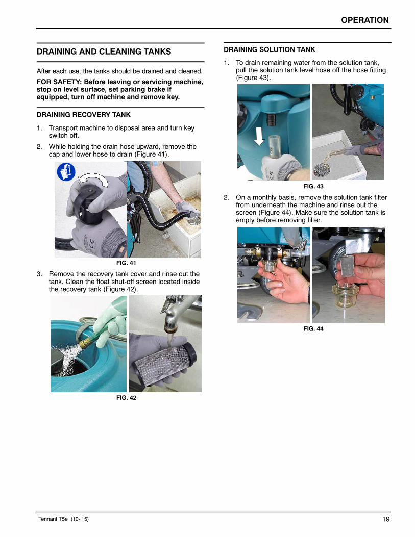
DRAINING AND CLEANING TANKS
After each use, the tanks should be drained and cleaned.
FOR SAFETY: Before leaving or servicing machine,stop on level surface, set parking brake ifequipped, turn off machine and remove key.
DRAINING RECOVERY TANK
1. Transport machine to disposal area and turn keyswitch off.
2. While holding the drain hose upward, remove thecap and lower hose to drain (Figure 41).
FIG. 41
3. Remove the recovery tank cover and rinse out thetank. Clean the float shut-off screen located insidethe recovery tank (Figure 42).
FIG. 42
DRAINING SOLUTION TANK
1. To drain remaining water from the solution tank,pull the solution tank level hose off the hose fitting(Figure 43).
FIG. 43
2. On a monthly basis, remove the solution tank filterfrom underneath the machine and rinse out thescreen (Figure 44). Make sure the solution tank isempty before removing filter.
FIG. 44

OPERATION
20 Tennant T5e (10- 15)
CHARGING BATTERIES
FOR SAFETY: When servicing machine, wearpersonal protection equipment as needed. Avoidcontact with battery acid.
The lifetime of the batteries depends on their propermaintenance. To get the most life from the batteries:
S Do not charge the batteries more than once a dayand only after running the machine for a minimum of15 minutes.
S Do not leave the batteries partially discharged forlong period of time.
S Only charge the batteries in a well-ventilated area toprevent gas build up. Charge batteries in areas withambient temperatures 80F / 27C or less.
S Allow the charger to complete charging the batteriesbefore re-using the machine.
S Maintain the proper electrolyte levels of flooded (wet)batteries by checking levels weekly (See BATTERYMAINTENANCE).
WARNING: Batteries Emit Hydrogen Gas.Keep Sparks And Open Flame Away. Keep BatteryCompartment Open When Charging.
BATTERY CHARGER SPECIFICATIONS
S CHARGER TYPE:- FOR SEALED (Gel) BATTERIES- FOR WET (Lead acid) BATTERIES
S OUTPUT VOLTAGE - 24 VOLTS
S OUTPUT CURRENT - 20 AMPS
S AUTOMATIC SHUTOFF CIRCUIT
S FOR DEEP CYCLE BATTERY CHARGING
ON-BOARD BATTERY CHARGER SETTINGS
If your machine is equipped with the on- board charger,the charger settings must be set for your battery typebefore charging. Failure to properly set will result inbattery damage.
To determine your battery type, see battery label.Contact your battery supplier if not specified.
To verify the setting of the charger, connect the chargercord into an electrical receptacle. The charger willdisplay a sequence of codes. One of the codes willeither read “GEL” or “Acd” (Figure 45).
GEL = Set for sealed/maintenance free batteriesAcd = Set for wet/lead acid batteries
FIG. 45
To change the setting, unplug the charger, peel up thecorner of the display label and set the switchesaccordingly (Fig. 46). The charger cord must beunplugged when resetting.
Sealed BatteryChargers mfd before 09/2012
Wet Battery
Sealed Battery(AGM MK)
Sealed Battery(AGM Discover)
FIG. 46

OPERATION
Tennant T5e (10- 15) 21
USING THE ON-BOARD BATTERY CHARGER(220- 240V Chargers)
IMPORTANT: Before charging, make sure that thecharger setting is properly set for your battery type(See ON-BOARD CHARGER SETTINGS).
1. Transport the machine to a well- ventilated area.
2. Park the machine on a flat, dry surface. Turn thekey off and set the parking brake, if equipped.
3. If charging wet (lead acid) batteries check the fluidlevel before charging (See BATTERYMAINTENANCE).
4. Prop up the recovery tank for ventilation(Figure 47).
FIG. 47
5. Connect the charger’s AC power supply cord into aproperly grounded receptacle (Figure 48).
NOTE: The machine will not operate when charging.
FIG. 48
6. The charger will display a sequence of codes oncethe cord is connected (Figure 49).Three- digits + the following code:
A = Charging current
U = Battery voltageh = Charging timeC = Charging ampere- hours [Ah]E = Energy used [Kwh]“GEL” or “Acd” = Battery type the charger iscurrently set for. Before charging make sureyour battery type matches the display:GEL=Sealed, Acd=Wet (lead acid). To changesetting, see ON- BOARD CHARGERSETTINGS.
Press the arrow button to review the codes.
FIG. 49
7. Once the charging cycle begins, the indicator lightswill progress from red, yellow to green. When thegreen indicator light comes on, the charging cycleis done. Unplug the charger cord.
If the charger detects a problem, the charger willdisplay an error code (See ON- BOARD BATTERYCHARGER ERROR CODES).
USING THE ON-BOARD BATTERY CHARGER(120V Chargers)
IMPORTANT: Before charging, make sure that thecharger setting is properly set for your battery type(See ON-BOARD CHARGER SETTINGS).
1. Transport the machine to a well- ventilated area.
2. Park the machine on a flat, dry surface. Turn thekey off and set the parking brake, if equipped.
3. If charging wet (lead acid) batteries check the fluidlevel before charging (See BATTERYMAINTENANCE).
4. Open the battery compartment and attach the redhandle battery connector harness to the batterycharger connector as shown (Figure 50).

OPERATION
22 Tennant T5e (03- 2015)
FIG. 50
5. Unwrap the battery charger’s AC power cord fromstorage hooks located on the underside of therecovery tank (Figure 51).
FIG. 51
6. Connect the charger’s AC power supply cord into aproperly grounded receptacle (Figure 52).
Grounded3 Hole Outlet
Ground Pin
FIG. 52
7. Using the support stand, prop up the recovery tankto allow for proper ventilation when chargingbatteries (Figure 53).
FIG. 53
NOTE: The machine will not operate when charging.
8. At start up, the charger will display a sequence ofcodes (Figure 54).Three- digits + the following code:
A = Charging currentU = Battery voltageh = Charging timeC = Charging ampere- hours [Ah]E = Energy used [Kwh]“GEL” or “Acd” = Battery type the charger iscurrently set for. Before charging make sureyour battery type matches the display:GEL=Sealed, Acd=Wet (lead acid). To changesetting, see ON- BOARD CHARGERSETTINGS.
Press the arrow button to review the codes.
FIG. 54
9. When the charging cycle begins, the indicator lightswill progress from red, yellow to green. When thegreen indicator light comes on, the charging cycleis done.
If the charger detects a problem, the charger willdisplay an error code (See ON- BOARD BATTERYCHARGER ERROR CODES).

OPERATION
Tennant T5e (10- 06) 23
10. When the charge cycle is complete, unplug the ACcord and return cord to storage hooks thendisconnect the red handle battery connector(Figure 55).
FIG. 55
ON-BOARD BATTERY CHARGER ERROR CODES
DISPLAY CODE FAULT SOLUTION
bat Loose or damaged battery cable Check battery cable connections.
Battery exceeded maximum voltage level. No action necessary.
E01 Exceeded maximum battery voltage allowed. No action necessary.
E02 Safety thermostat exceeded maximum internaltemperature.
Check if the charger vents are obstructed.
E03 Exceeded maximum time for charging phaseleaving the batteries undercharged due to asulfated or faulty battery.
Repeat the charging cycle and if the errorcode E03 reappears check battery or re-place it.
SCt Safety timer exceeded maximum chargingtime. Interrupts charging cycle.
Replace battery.
Srt Possible internal short circuit. Contact Service Center.
USING AN OFF-BOARD BATTERY CHARGER
FOR SAFETY: When servicing machine, the use ofincompatible battery chargers may damage batterypacks and potentially cause a fire hazard. Inspectcharger cord regularly for damage.1. Transport the machine to a well- ventilated area.
2. Park the machine on a flat, dry surface. Turn thekey off and set the parking brake, if equipped.
FOR SAFETY: Before leaving or servicing machine,stop on level surface, set parking brake ifequipped, turn off machine and remove key.3. If charging wet (lead acid) batteries, check the fluid
level before charging (See BATTERYMAINTENANCE).
4. Prop up the recovery tank for ventilation(Figure 56).
FIG. 56
5. Connect the charger’s AC power supply cord into aproperly grounded receptacle.
6. Connect the charger’s DC cord into the machine’sbattery receptacle (Figure 57).

OPERATION
24 Tennant T5e (10- 15)
FIG. 57
7. The supplied charger will automatically begincharging and shut off when fully charged.
NOTE: The machine will not operate when charging.ATTENTION: Do not disconnect the charger’s DCcord from the machine’s receptacle when thecharger is operating. Arcing may result. If thecharger must be interrupted during charging,disconnect the AC power supply cord first.
ADJUSTING SCRUB HEAD BRUSHES
To ensure optimum scrubbing performance periodicallycheck the scrub head for proper adjustment.
FOR SAFETY: Before leaving or servicing machine,stop on level surface, set parking brake ifequipped, turn off machine and remove key.
DISK MODEL
Tools required: Measuring device, 1- 1/16 in (27mm)wrench and 15/16 in (24mm) wrench.
1. With brushes installed, lower the scrub head andapply medium brush pressure.
2. Turn machine off and remove key.
3. From the center front and back of scrub head,measure the distance from the top edge of scrubhead to the floor (Figure 58).
FIG. 58
4. If scrub head is not level, loosen the lock nut andturn the scrub head leveling screw to level. Tightendown the lock nut once head is level (Figure 59).
LockNut
FIG. 59

OPERATION
Tennant T5e (10- 15) 25
CYLINDRICAL BRUSH MODEL
After installing a new set of cylindrical brushes checkthe brush pattern to ensure proper brush adjustment.Brushes that are not properly adjusted will result inpremature wear and poor scrubbing performance(Figure 60).
CORRECT BRUSH PATTERN
INCORRECT BRUSH PATTERNS
EvenPattern
TaperedPattern
UnevenPattern
FIG. 60
To Inspect the Brush Pattern:
1. Position the machine on a dry dusty floor or apply apowdered substance, such as chalk.
2. Disconnect the drive motor wire connector to keepmachine from moving forward (Figure 61).
FIG. 61
3. Lower the scrub head to the floor and applymaximum brush pressure.
4. Shut off the solution flow.
5. Pull the triggers to create a brush pattern on thefloor.
6. Raise the scrub head and pull the machine away.
7. Observe the brush pattern on floor. If the brushpattern is uneven or tapered, adjustment isrequired.
8. Reconnect drive motor wire.
To Adjust an Uneven Brush Pattern:
Tools required: Measuring device, 27mm wrench and24mm wrench
1. Measure the distance from the front edge of thescrub head to the floor and from the back edge ofthe scrub head to the floor (Figure 62). Themeasurements should be the same.
FIG. 62
2. To level the scrub head, loosen the lock nut andturn the leveling screw clockwise to lower the rearof the scrub head or counter- clockwise to lower thefront (Figure 63).
FIG. 63
3. Recheck brush pattern.
NOTE: Replace brushes when bristles are worn to 15mm.

OPERATION
26 Tennant T5e (10- 15)
To Adjust a Tapered Brush Pattern:
Tools required: 10mm wrench and 6mm hex wrench
1. Raise the scrub head off floor and remove key.
2. Remove the idler plate from the brush (Figure 64).
FIG. 64
3. Hold the brush plug shaft with a wrench and loosenthe 6mm hex screw (Figure 65).
FIG. 65
4. To lower the brush end, turn the shaft clockwise forthe front brush and counter- clockwise for the rearbrush. Retighten hex screw (Figure 66).
FIG. 66
5. Recheck brush pattern.
NOTE: Replace brushes when bristles are worn to 15mm.

OPERATION
Tennant T5e (10- 15) 27
MACHINE MAINTENANCE
To keep the machine in good working condition, it’simportant that the following maintenance proceduresare performed on a routine basis.FOR SAFETY: Before leaving or servicing machine,stop on level surface, turn off machine, remove keyand set parking brake if equipped.
FOR SAFETY: When servicing machine, wearpersonal protection equipment as needed.
DAILY MAINTENANCE (After Every Use)1. Drain the recovery tank (Figure 67).
FIG. 672. Rinse out the recovery tank. Remove the recovery
tank float shut- off screen and clean (Figure 68).
FIG. 683. Drain the solution tank (Figure 69).
FIG. 69
4. Rotate pad or replace when worn (Figure 70).
Disk Model
FIG. 70
5. Replace brushes when they no longer cleaneffectively or when the bristles are worn to theyellow indicator (Figure 71).
FIG. 71
6. Empty and rinse out the debris trough (Figure 72).
Cylindrical Brush Model
FIG. 72

OPERATION
28 Tennant T5e (10- 15)
7. Inspect the cylindrical brushes for wear. Rotatebrushes from front- to- rear every 50 hours (Figure73). Replace when worn to a length of 15mm.
15mm
CylindricalBrush Model
FIG. 73
8. Remove debris buildup from the underside of thecylindrical brush scrub head, including the idlerplates and drive hubs (Figure 74).
Cylindrical Brush Model
FIG. 74
9. Wipe the squeegee blades clean (Figure 75). Storethe squeegee assembly in the raised position toprevent blade damage.
FIG. 75
10. Check the condition of the squeegee blade wipingedge (Figure 76). Rotate blade if worn (SeeSQUEEGEE BLADES).
FIG. 76
11. Clean the machine with an all purpose cleaner anddamp cloth (Figure 77).
FOR SAFETY: When servicing machine, do notpower spray or hose off machine.
FIG. 77
12. Inspect the condition of the scrub head skirt,replace if worn or damaged (Figure 78).
Cylindrical Brush Model
FIG. 78
13. FaST Model: Connect the FaST- PAK supply hoseto the storage plug when not in use (Figure 79).Remove any dried concentrate from the hoseconnector by soaking it in warm water.

OPERATION
Tennant T5e (10- 15) 29
FIG. 79
14. Recharge the batteries (Figure 80). SeeCHARGING BATTERIES.
FIG. 80
15. Check the battery electrolyte level weekly (SeeBATTERY MAINTENANCE).
16. Clean wet/lead acid batteries to prevent corrosionand check for loose battery cable connections (SeeBATTERY MAINTENANCE).
MONTHLY MAINTENANCE
1. Remove the solution tank filter from underneath themachine and rinse out the screen (Figure 81).Make sure the solution tank is empty beforeremoving filter.
FIG. 81
2. Periodically check the belt tension on the two brushmotors. Tighten the belt if you’re able to twist itbeyond 90_ at midpoint (Figure 82).
FOR SAFETY: Before leaving or servicing machine,stop on level surface, turn off machine, remove keyand set parking brake if equipped.
Cylindrical Brush Model
FIG. 823. Inspect and clean the recovery tank cover seal
(Figure 83). Replace if damaged.
FIG. 83
4. Lubricate all pivot points and rollers with a waterresistant grease.
5. Lubricate the casters with a water resistant grease(Figure 84).
FIG. 84
6. Clean the parking brake clamp with a cleaningsolvent.
7. Check the machine for loose nuts and bolts.
8. Check the machine for leaks.

OPERATION
30 Tennant T5e (10- 15)
BATTERY MAINTENANCE
FOR SAFETY: Before leaving or servicing machine,stop on level surface, turn off machine, remove keyand set parking brake if equipped.
FOR SAFETY: When servicing machine, wearpersonal protection equipment as needed. Avoidcontact with battery acid.
MAINTENANCE-FREE BATTERIES
Maintenance-free (Sealed AGM) batteries do notrequire watering. Cleaning and other routinemaintenance is still required.
FLOODED (WET) LEAD-ACID BATTERIESThe flooded (wet) lead-acid batteries require routinewatering as described below. Check the batteryelectrolyte level weekly.
The electrolyte level should be slightly above thebattery plates as shown before charging (Figure 85).Add distilled water if low. DO NOT OVERFILL. Theelectrolyte will expand and may overflow whencharging. After charging, distilled water can be addedup to about 3 mm (0.12 in) below the sight tubes.
Before Charging After Charging
FIG. 85
NOTE: Make sure the battery caps are in place whilecharging. There may be a sulfur smell after chargingbatteries. This is normal.
CHECKING CONNECTIONS / CLEANINGAfter every 200 hours of use, check for loose batteryconnections and clean the surface of the batteries,including terminals and cable clamps to prevent batterycorrosion. Use a scrub brush with a strong mixture ofbaking soda and water (Figure 86). Do not removebattery caps when cleaning batteries.
FIG. 86

OPERATION
Tennant T5e (10- 15) 31
SQUEEGEE BLADES
FOR SAFETY: Before leaving or servicing machine,stop on level surface, turn off machine, remove keyand set parking brake if equipped.
When the blades become worn, simply rotate theblades end-for-end or top-to-bottom to a new wipingedge. Replace blades when all edges are worn.
The front blades on the 700mm/800mm squeegeeassemblies have 12/14 slots on one edge and 6 slotson the opposite edge (Figure 87). If making sharp turnswith the cylindrical brush models use the 12/14 slottededge for maximum water pickup.
6 Slots onone edge
12/14 Slots onopposite edge
FIG. 87
Replacing Squeegee Blades:
1. Loosen the band clamp and remove the band fromthe squeegee assembly (Figure 88).
FIG. 88
2. Replace or rotate the rear blade to a new wipingedge and replace band (Figure 89).
FIG. 89
3. To change the front blade, remove the band andloosen the four knobs. Replace or rotate the frontblade to a new wiping edge (Figure 90)
FIG. 90
MOTOR MAINTENANCE
Contact an Authorized Tennant Service Center forcarbon brush replacement.
Carbon Brush Replacement Hours
Drive Transaxle Motor
750Vacuum Motor
Disk Brush Motors
Cylindrical Brush Motors 1000
WARNING: Electrical Hazard. DisconnectBattery Cables Before Servicing Machine.
OPERATION
32 Tennant T5e (10- 15)
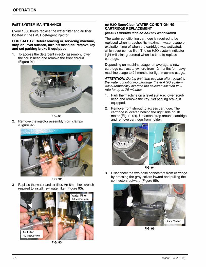
FaST SYSTEM MAINTENANCE
Every 1000 hours replace the water filter and air filterlocated in the FaST detergent injector.
FOR SAFETY: Before leaving or servicing machine,stop on level surface, turn off machine, remove keyand set parking brake if equipped.
1. To access the detergent injector assembly, lowerthe scrub head and remove the front shroud(Figure 91)
FIG. 91
2. Remove the injector assembly from clamps(Figure 92).
FIG. 92
3 Replace the water and air filter. An 8mm hex wrenchrequired to install new water filter (Figure 93).
Water Filter(50 Mesh/Brown)
Air Filter(50 Mesh/Brown)
FIG. 93
ec-H2O NanoClean WATER CONDITIONINGCARTRIDGE REPLACEMENT(ec-H2O models labeled ec-H2O NanoClean)
The water conditioning cartridge is required to bereplaced when it reaches its maximum water usage orexpiration time of when the cartridge was activated,which ever comes first. The ec-H2O system indicatorlight will blink green/red when it’s time to replacecartridge.
Depending on machine usage, on average, a newcartridge can last anywhere from 12 months for heavymachine usage to 24 months for light machine usage.
ATTENTION: During first time use and after replacingthe water conditioning cartridge, the ec-H2O systemwill automatically override the selected solution flowrate for up to 75 minutes.
1. Park the machine on a level surface, lower scrubhead and remove the key. Set parking brake, ifequipped.
2. Remove front shroud to access cartridge. Thecartridge is located behind the right side brushmotor (Figure 94). Unfasten strap around cartridgeand remove cartridge from holder.
FIG. 94
3. Disconnect the two hose connectors from cartridgeby pressing the gray collars inward and pulling theconnectors outward (Figure 95).
Gray Collar
FIG. 95

OPERATION
Tennant T5e (03- 15) 33
4. Fill in the installation date on the new cartridgelabel (Figure 96).
FIG. 96
5. Reconnect the two hoses to new cartridge andre-strap cartridge to holder. Make sure the hoseconnectors are fully inserted into new cartridge.
6. Reset timer for new cartridge.
Carefully read and understand all steps first beforeperforming procedure.a. Turn key on.b. Press and hold the service switch, located on
the ec-H2O module, for 10 seconds. Afterreleasing service switch, the three solution flowindicator lights will begin to (ripple) move backand forth (Figure 97).
c. Within 5 seconds after releasing the serviceswitch, while the three indicator lights aremoving back and forth, press and quicklyrelease the solution flow button located onec-H2O module (Figure 97).The three indicator lights will then blink threetimes to indicate timer has been reset.Repeat process if the three indicator lights donot blink three times.
Service switch3 indicator lights
Solution flow button
FIG. 97
ec-H2O MODULE FLUSH PROCEDURE
(ec-H2O models manufactured before ec-H2ONanoClean models)
This procedure is only required when an alarm soundsand the ec-H2O system indicator light begins to blinkred.
FOR SAFETY: Before leaving or servicing machine,stop on level surface, turn off machine, remove keyand set parking brake if equipped.
1. Drain the solution tank and recovery tank of allwater.
2. Pour 1 gallon (4 liters) of white or rice vinegar intothe solution tank at full strength. Do not dilute.
NOTE: Use white or rice vinegar only. The aciditylevel should be between 4- 8%. Do not use other acidsfor this procedure.
3. Disconnect the black connector fitting at the scrubhead and place the hose into a bucket (Figure 98).To access the connector fitting, you may have toremove the front cover from the machine.
FIG. 98
4. Turn the key to the on ( I ) position.

OPERATION
34 Tennant T5e (10- 15)
5. Press and release the ec-H2O module flush switchto start the flush cycle (Figure 99). The module islocated under the recover tank.
NOTE: The module will automatically shut off when theflush cycle is complete (approx. 7 minutes). Themodule must run the full 7 minute cycle in order toreset the system indicator light and alarm.
Repeat flush procedure if the ec-H2O module doesnot reset. If module fails to reset, contact anAuthorized Service Center.
FIG. 99
JACKING UP MACHINE
Use the designated locations to jack up the machine forservice (Figure 100). Empty the recovery and solutiontank and position the machine on a level before jacking.
FOR SAFETY: When servicing machine, jackmachine up at designated locations only. Use jackor hoist that will support machine weight.
FIG. 100
TRANSPORTING MACHINE
When transporting the machine by trailer or truck, becertain to follow the transporting procedure below:
1. Drain machine tanks.
2. Load the machine using a ramp that can supportthe machine weight and person loading it. Themaximum ramp incline should not exceed 19.5% ata ramp length of 12 ft (3.7m).
FOR SAFETY: When loading/unloading machineonto/off truck or trailer, use a ramp, truck or trailerthat will support the weight of the machine andoperator. Use tie- down straps to secure machineto truck or trailer.
3. Position the front of machine up against the front ofthe trailer or truck. Lower the scrub head andsqueegee.
4. Set the parking brake, if equipped, and place ablock behind each wheel to prevent the machinefrom rolling.
5. Secure with tie- down straps as shown (Figure101). It may be necessary to install tie-downbrackets to trailer or truck.
FIG. 101
STORING MACHINE
1. Charge the batteries before storing machine toprolong the life of the batteries. Recharge batteriesonce a month.
2. Disconnect batteries before storing.
3. Drain and rinse the tanks thoroughly.
4. Store the machine in a dry area with the squeegeeand scrub head in the up position.
5. Open the recovery tank cover to promote aircirculation.
ATTENTION: Do not expose machine to rain, storeindoors.
6. If storing machine in freezing temperatures, followthe FREEZE PROTECTION instructions below.

OPERATION
Tennant T5e (03- 15) 35
FREEZE PROTECTION
FOR SAFETY: Before leaving or servicing machine,stop on level surface, turn off machine, remove keyand set parking brake if equipped.
1. Drain the solution tank and recovery tank of allwater.
2. Empty the solution tank filter located under themachine (Figure 102).
FIG. 102
3. Pour 1 gallon (4 liters) of recreational vehicle (RV)antifreeze into the solution tank at full strength.Do not dilute.
4. Turn the machine power on and operate thesolution flow system. Turn the machine off whenthe red RV antifreeze is visible.
If your machine is equipped with the off- aisle wandoption, operate the the off- aisle wand for a fewseconds to protect the pump.
Continue with the freeze protection procedure ifmachine is equipped with the FaST or ec-H2O system.
ec-H2O NanoClean Models:(ec-H2O models labeled ec-H2O NanoClean)
Operate machine in the ec-H2O mode to cycleantifreeze through ec-H2O system.
After storing machine in freezing temperatures, drainany remaining antifreeze from the solution tank. Addclean water to solution tank and operate the machine toflush system.
ec-H2O Models:(ec-H2O models manufactured before ec-H2ONanoClean models)Press and release the flush switch on the ec-H2Omodule to cycle the antifreeze through ec-H2O system(Figure 103). When the antifreeze is visible, press theswitch again to turn off the module.
FIG. 103
IMPORTANT: Before operating machine, the antifreezemust be flushed from the module as described below.
If the antifreeze is not properly flushed from theec-H2O system, the ec-H2O module may detect anerror and not function (ec-H2O switch indicator light willturn red). If this occurs, reset key and repeat the flushprocedure as described below.
Flushing antifreeze from ec-H2O module:
(ec-H2O models manufactured before ec-H2ONanoClean models)
1. Drain the antifreeze from the solution tank into abucket.
2. Fill the solution tank with cool water until full (SeeFILLING SOLUTION TANK).
3. Disconnect the black connector fitting at the scrubhead and place the hose into a bucket (Figure104). To access the connector fitting, you mayhave to remove the front cover from the machine.
FIG. 104
4. Press and release the ec-H2O module switch toflush the antifreeze from the ec-H2O system(Figure 103). The module is located under therecovery tank.
When the water turns clear, press the moduleswitch again to stop the flush cycle.
Dispose the antifreeze in an environmentally safe wayaccording to local waste disposal regulations.5. The machine is now ready for scrubbing.

OPERATION
36 Tennant T5e (10- 15)
FaST Model:
The following items are required: valve coupling#1002856 and 6 in (15 cm) hose #63182.
1. Remove the FaST- PAK carton and connect thevalve coupling and 6 in (15 cm) hose to the FaSTdetergent supply hose (Figure 105).
FIG. 105
2. Disconnect the opposite end of the FaST supplyhose from the injector assembly and drain thedetergent from the hose (Figure 106). Reconnectthe hose after draining. To access the injectorassembly remove the front cover.
FIG. 106
3. Pour the recreational vehicle (RV) antifreeze intothe supply hose until full (Figure 107).
4. Keep the hose upright to prevent the antifreezefrom spilling and lower the recovery tank.
FIG. 107
5. Operate the FaST system until the foaming stops.This step could take anywhere from 5 to 10minutes.
6. When finished, connect the supply hose to thestorage plug (Figure 108).
FIG. 108
7. To drain the antifreeze from the FaST supply hose,repeat steps 1 and 2.
Dispose of the antifreeze in an environmentallysafe way according to local waste disposalregulations.

OPERATION
Tennant T5e (10- 06) 37
TROUBLESHOOTING
PROBLEM CAUSE SOLUTION
Machine will not operate Discharged batteries Charge batteries
Emergency- stop button activated Turn button clockwise to reset
Faulty battery(s) Replace battery(s)
Loose battery cable Tighten loose cable
Tripped main circuit breaker Reset 10A main circuit breaker
Main fuse blown Replace 100A main fuse
Faulty key switch Contact Service Center
Machine fault detected. See Battery Meter LED Fault Codes
On- board battery chargerwill not operate
Plug not connected to power supply Check plug connection
Faulty charger fuse Replace charger fuse
Faulty power supply cord Replace cord
Error detected. See On- board Battery Charger Error Codes
Brush motor(s) will not op-erate
Scrub head is raised off floor Lower scrub head
Battery meter lockout activated Recharge batteries
Discharged batteries Charge batteries
Tripped brush motor circuit breaker Reset 25A circuit breaker button
Faulty scrub head (up/down) switch Contact Service Center
Faulty trigger switch(es) Contact Service Center
Faulty brush motor or wiring Contact Service Center
Worn carbon brushes Contact Service Center
Broken or loose belt(cylindrical brush model)
Replace or tighten belt
Faulty relay switch Contact Service Center
Machine will not propel Parking brake is set Release parking brake lever
Machine fault detected See Battery Meter LED Fault Codes
Propel motor fuse blown Replace 30A fuse
Faulty transaxle motor or wiring Contact Service Center
Worn carbon brushes Contact Service Center
Exceeded maximum incline Avoid steep inclines and reset key
Vacuum motor will not op-erate
Squeegee is raised off floor Lower squeegee
Discharged batteries Charge batteries
Tripped vacuum motor circuit breaker Reset 25A circuit breaker button
Faulty vacuum motor or wiring Contact Service Center
Worn carbon brushes Contact Service Center
Little or no solution flow Solution tank is empty Fill solution tank
Clogged solution tank filter Clean solution tank filter
Discharged batteries Charge batteries
Clogged solution valve Remove valve and clean
Solution flow control knob set too low Adjust solution control flow knob
Loose screw on control knob Calibrate knob and retighten screw.

OPERATION
38 Tennant T5e (10- 06)
TROUBLESHOOTING - Continued
PROBLEM CAUSE SOLUTION
Poor water pickup Recovery tank is full or excessive foambuildup
Drain recovery tank
Loose drain hose cap Tighten cap
Clogged float shut- off screen located inrecovery tank
Clean screen
Clogged squeegee assembly Clean squeegee assembly
Worn squeegee blades Replace or rotate squeegee blades
Incorrect Squeegee blade deflection Adjust Squeegee blade height
Loose vacuum hose connections Secure hose connections
Clogged vacuum hose Remove clogged debris
Damaged vacuum hose Replace vacuum hose
Recovery tank cover not in place Properly position cover
Damaged recovery tank cover seal Replace seal
Faulty vacuum motor Contact Service Center
Low battery charge Recharge batteries
Poor scrubbing perfor-mance
Debris caught in brush Remove debris
Worn brushes/pads Replace brushes/pads
Incorrect brush pressure setting Adjust pressure setting
Wrong brush/pad type. Use correct brush/pad
Reduced run time Batteries not fully charged Fully recharge batteries
Defective batteries Replace battery
Batteries need maintenance See BATTERY MAINTENANCE
Faulty battery charger Repair or replace battery charger
FaST Model: FaST Sys-tem does not operate oroperate correctly
FaST system switch is not turned on Turn on FaST system switch
FaST- PAK supply hose not connected Connect supply hose
Clogged FaST- PAK supply hose or con-nectors
Soak in warm water to unclog
Empty FaST- PAK carton Replace FaST- PAK carton
Kink in FaST- PAK supply hose Undo hose kink
Clogged FaST solution system Contact Service Center
Faulty FaST system on/off switch Contact Service Center
Faulty pump Contact Service Center
Clogged solution tank filter Drain solution tank. Remove solution tankfilter, clean and reinstall
Clogged detergent orifice/filter screen Replace orifice/filter screen(See FaST SYSTEM MAINTENANCE)
Clogged FaST solution inlet filter Contact Service Center
FaST Pump fuse blown Replace 7.5A fuse

OPERATION
Tennant T5e (03- 15) 39
TROUBLESHOOTING - Continuedec-H2O NanoClean Models (ec-H2O models labeled ec-H2O NanoClean)
PROBLEM CAUSE SOLUTION
ec-H2O system indicatorlight blinking green/red
Water conditioning cartridge has expired Replace cartridge (See ec-H2O NanoCleanWATER CONDITIONING CARTRIDGEREPLACEMENT)
ec-H2O system indicatorlight is red or blinking* red
ec-H2O system fault has been detected Contact Service Center
*Verify if cleaning detergent was added to solution tank. If ec-H2O system was operated with cleaning detergent, drain solutiontank, add clear water and operate the ec-H2O system until the indicator light code clears.
ec-H2O Models (ec-H2O models manufactured before ec-H2O NanoClean models)
PROBLEM CAUSE SOLUTION
ec-H2O system indicatorlight blinking red
Mineral deposit build- up in module Flush module (See ec-H2O MODULEFLUSH PROCEDURE)
Alarm sounds
ec-H2O system indicatorlight solid red
The freeze protection antifreeze was notremoved prior to using machine
Flush antifreeze from module.See FIRST TIME USE for flushing instruc-tions.
Defective module Contact Service Center
ec-H2O system indicatorlight does not turn on
Defective light or module Contact Service Center
No water flow Clogged module Contact Service Center
Defective solution pump Contact Service Center
BATTERY METER LED FAULT CODES
CODE(Flashing LED Bars)
FAULT SOLUTION
One Low voltage shut- off.Scrubbing function stops.
Recharge batteries.
Check battery connection.
Two Battery charge level getting low. Recharge batteries.
Three Drive motor tripped. Remove overload condition and reset key.
Short circuit to drive motor. Contact Service Center.
Four Battery lockout. Recharge batteries immediately.
Eight Controller tripped. Contact Service Center.
Ten High battery voltage reading. Check battery connections.
No Bars Sleep mode. Turn key to restore.
Bars Rippling Throttle engaged at start up. Release triggers.

OPERATION
40 Tennant T5e (03- 15)
MACHINE SPECIFICATIONSMODEL Disk,
600mmDisk,700mm
Disk,800mm
Cylindrical,650mm
Cylindrical,800mm
LENGTH 1,357 mm 1,408 mm 1,471 mm 1,399 mm 1,399 mm
WIDTH 645 mm 737 mm 838 mm 711 mm 864 mm
HEIGHT 1,120 mm
MINIMUM AISLE TURN 1,346 mm 1,499 mm 1,626 mm 1,575 mm 1,638 mm
WEIGHT 133 kg 145 kg 151 kg 151 kg 155 kg
WEIGHT WITH BATTERIES 258 kg 269 kg 275 kg 275 kg 279 kg
RECOVERY TANK CAPACITY 105 L
SOLUTION TANK CAPACITY 85 L
DRIVE SYSTEM Transaxle, 24 V, .19 kW
TRAVEL SPEED, MAXIMUM Cleaning: 67 m/min Transporting: 72 m/min
PRODUCTIVITY RATETheoretical
2,450 m2/hr 2,860 m2/hr 3,270 m2/hr 2,660 m2/hr 3,270 m2/hr
PRODUCTIVITY RATEEstimated Actual
1,660 m2/hr 1,930 m2/hr 2,230 m2/hr 1,785 m2/hr 2,230 m2/hr
CLEANING PATH WIDTH 600 mm 700 mm 800 mm 650 mm 800 mm
BRUSH DIAMETER 302 mm 353 mm 404 mm 151 mm 151 mm
BRUSH PRESSURE Up to 54 kg
SOLUTION FLOW RATE 1.89 L /min 1.89 L/min 2.27 L/min 2.27 L/min
SQUEEGEE WIDTH 908 mm standard 1,051 mm standard 1,185 mm standard 1,051 mm standard 1,185 mm standard
800 mmnarrow aisle
908 mmnarrow aisle
1,051 mmnarrow aisle
908 mmnarrow aisle
1,051 mmnarrow aisle
BRUSH MOTOR Qty 2, .55 kW, 220rpm, 24 V, 29 A Qty 2, .47 kW, 1500 rpm, 24 V, 23 A
VACUUM MOTOR 640 W, 3- stage 5.7, 24 V, 26 A
WATER LIFT/AIR FLOW 55 mm H2O/ 32.4 L3/m
BATTERIES Qty 4, 6 V
BATTERY CAPACITY WET (lead Acid) = 235Ah @ 20 h rate Sealed (Gel)= 200Ah @ 20 h rate
RUN TIME PER CHARGE* WET = Up to 5.0 hours Gel = Up to 4.0 hours
ON-BOARD CHARGER 120VAC, 10A, 50/60Hz, 24VDC, 20A output / 230VAC, 5A, 50/60Hz, 24VDC, 20A output
TOTAL POWER CONSUMPTION 50 A nominal
VOLTAGE DC 24 VDC
PROTECTION GRADE IPX3
DECIBEL RATING AT OPERA-TOR’S EAR, INDOORS.** 67dBA 68dBA
VIBRATION AT CONTROLS <.1188 m/s2 <.103 m/s2
ACCELERATION RATE ONOPERATOR - MAX. .179 m /s2
GRADE LEVEL, MAX. Scrubbing 5%, Transporting 8%, Ramp Loading 19.5%
* Run times are based on Continuous Scrubbing Run Times.
** Sound levels (ISO 11201) as recommended by the American Association of Cleaning Equipment Manufacturers (AACEM) and OSHA.

OPERATION
Tennant T5e (03- 15) 41
FaST SYSTEM Disk,600mm
Disk,700mm
Disk,800mm
Cylindrical,650mm
Cylindrical,800mm
PRODUCTIVITY RATEEstimated Actual
1865 m2/hr 2115 m2/hr 2440 m2/hr 1950 m2/hr 2440 m2/hr
SOLUTION PUMP 24 Volt DC, 3.5 A, 5.6 L/min open flow, 4.13 Bar bypass setting
SOLUTION FLOW RATE 0.57 L/min. 0.83 L/min. 0.57 L/min. 0.83 L/min.
CONCENTRATE FLOW RATE 0.57 CC/min. 0.83 CC/min. 0.57 CC/min. 0.83 CC/min.
CONCENTRATE TO WATERDILUTION RATIO 1:1000
ec-H2O SYSTEM Disk,600mm
Disk,700mm
Disk,800mm
Cylindrical,650mm
Cylindrical,800mm
PRODUCTIVITY RATEEstimated Actual
1865 m2/hr 2115 m2/hr 2440 m2/hr 1950 m2/hr 2440 m2/hr
SOLUTION PUMP 24 Volt DC, 3.5 A, 5.6 L/min open flow, 4.13 Bar bypass setting
SOLUTION FLOW RATE* 0.57 L/min.(standard)
0.83 L/min.(standard)
0.83 L/min.(standard)
1.25 L/min.(standard)
0.83 L/min.(optional)
1.25 L/min.(optional)
1.14 L/min.(optional)
1.67 L/min.(optional)
1.14 L/min.(optional)
1.67 L/min.(optional)
* ec-H2O models manufactured before ec-H2O NanoClean Models - If the optional solution flow rates are required, contact an Authorized Service
Center.
MACHINE DIMENSIONS
A
B
1120 mm
C
Models: 600 mm 700 mm 800 mm 650 mm 800 mmDisk Disk Disk Cylindrical Cylindrical
A = 1,357 mm 1,408 mm 1,471 mm 1,399 mm 1,399 mmB = 645 mm 737 mm 838 mm 711 mm 864 mmC = 908 mm 1,051 mm 1,185 mm 1,051 mm 1,185 mm