T3 Mapper MegaCore Function T3MAP - Altera · PDF fileiv Altera Corporation About this User...
32
A-UG-IPT3MAP-1.01 T3MAP T3 Mapper MegaCore Function 101 Innovation Drive San Jose, CA 95134 (408) 544-7000 http://www.altera.com User Guide October 2001
Transcript of T3 Mapper MegaCore Function T3MAP - Altera · PDF fileiv Altera Corporation About this User...

A-UG-IPT3MAP-1.01
T3MAP
T3 Mapper MegaCore Function
101 Innovation DriveSan Jose, CA 95134(408) 544-7000http://www.altera.com
User GuideOctober 2001

ii Altera Corporation
T3 Mapper MegaCore Function (T3MAP) User Guide Copyright
Copyright © 2001 Altera Corporation. Altera, The Programmable Solutions Company, the stylized Altera logo, specific devicedesignations, and all other words and logos that are identified as trademarks and/or service marks are, unless noted otherwise,the trademarks and service marks of Altera Corporation in the U.S. and other countries. All other product or service names arethe property of their respective holders. Altera products are protected under numerous U.S. and foreign patents and pendingapplications, maskwork rights, and copyrights. Altera warrants performance of its semiconductor products to currentspecifications in accordance with Altera’s standard warranty, but reserves the right to make changes to any products and servicesat any time without notice. Altera assumes no responsibility or liability arising out of the application or use of any information,product, or service described herein except as expressly agreed to in writing by Altera Corporation. Alteracustomers are advised to obtain the latest version of device specifications before relying on any publishedinformation and before placing orders for products or services. All rights reserved

About this User Guide
User Guide
This user guide provides comprehensive information about the Altera® T3 Mapper MegaCore® Function (T3MAP).
Table 1 shows the user guide revision history
� Go to the following sources for more information:
� See “Features” on page 9 for a complete list of the core features, including new features in this release.
� Refer to the T3MAP readme file for late-breaking information that is not available in this user guide.
How to Find Information
� The Adobe Acrobat Find feature allows you to search the contents of a PDF file. Click on the binoculars icon in the top tool bar to open the Find dialog box, or click the right mouse button for a pull-down menu.
� Bookmarks serve as an additional table of contents.� Thumbnail icons, which provide miniature previews of each page,
provide a link to the pages.� Numerous links, shown in green text, allow you to jump to related
information.
Table 1. Revision History
Date Description
October 2001 First revision.
February 2001 Initial release of this document.
Altera Corporation iii

About this User Guide T3 Mapper MegaCore Function (T3MAP) User Guide
How to Contact Altera
For the most up-to-date information about Altera products, go to the Altera world-wide web site at http://www.altera.com.
For additional information about Altera products, consult the sources shown in Table 2.
Note:(1) You can also contact your local Altera sales office or sales representative.
Table 2. How to Contact Altera
Information Type Access USA & Canada All Other Locations
Altera Literature Services
Electronic mail [email protected] (1) [email protected] (1)
Non-technical customer service
Telephone hotline (800) SOS-EPLD (408) 544-7000 (7:30 a.m. to 5:30 p.m. Pacific Time)
Fax (408) 544-7606 (408) 544-7606
Technical support Telephone hotline (800) 800-EPLD(7:00 a.m. to 5:00 p.m. Pacific Time)
(408) 544-7000 (1)(7:30 a.m. to 5:30 p.m. Pacific Time)
Fax (408) 544-6401 (408) 544-6401 (1)
Electronic mail [email protected] [email protected]
FTP site ftp.altera.com ftp.altera.com
General product information
Telephone (408) 544-7104 (408) 544-7104 (1)
World-wide web site http://www.altera.com http://www.altera.com
iv Altera Corporation

T3 Mapper MegaCore Function (T3MAP) User Guide About this User Guide
Typographic Conventions
The T3 Mapper MegaCore Function (T3MAP) User Guide uses the typographic conventions shown in Table 3.
Table 3. Conventions
Visual Cue Meaning
Bold Type with Initial Capital Letters
Command names, dialog box titles, checkbox options, and dialog box options are shown in bold, initial capital letters. Example: Save As dialog box.
bold type External timing parameters, directory names, project names, disk drive names, filenames, filename extensions, and software utility names are shown in bold type. Examples: fMAX, \maxplus2 directory, d: drive, chiptrip.gdf file.
Bold italic type Book titles are shown in bold italic type with initial capital letters. Example: 1999 Device Data Book.
Italic Type with Initial Capital Letters
Document titles are shown in italic type with initial capital letters. Example: AN 75 (High-Speed Board Design).
Italic type Internal timing parameters and variables are shown in italic type. Examples: tPIA, n + 1.Variable names are enclosed in angle brackets (< >) and shown in italic type. Example: <file name>, <project name>.pof file.
Initial Capital Letters Keyboard keys and menu names are shown with initial capital letters. Examples: Delete key, the Options menu.
“Subheading Title” References to sections within a document and titles of Quartus II and MAX+PLUS II Help topics are shown in quotation marks. Example: “Configuring a FLEX 10K or FLEX 8000 Device with the BitBlaster™ Download Cable.”
Courier type Signal and port names are shown in lowercase Courier type. Examples: data1, tdi, input. Active-low signals are denoted by suffix _n, e.g., reset_n.
Anything that must be typed exactly as it appears is shown in Courier type. For example: c:\max2work\tutorial\chiptrip.gdf. Also, sections of an actual file, such as a Report File, references to parts of files (e.g., the AHDL keyword SUBDESIGN), as well as logic function names (e.g., TRI) are shown in Courier.
1., 2., 3., and a., b., c.,... Numbered steps are used in a list of items when the sequence of the items is important, such as the steps listed in a procedure.
� Bullets are used in a list of items when the sequence of the items is not important.
� The checkmark indicates a procedure that consists of one step only.
� The hand points to information that requires special attention.
� The angled arrow indicates you should press the Enter key.
� The feet direct you to more information on a particular topic.
Altera Corporation v
About this User Guide T3 Mapper MegaCore Function (T3MAP) User Guide
Abbreviations & Acronyms
AHDL Altera hardware description languageAIRbus access to internal registers interfaceATM asynchronous transfer modeCDR clock data recoveryCPU central processing unitEDA electronic design automationESB embedded system blockFIFO first-in first-outIP intellectual propertyLE logic elementLSB least significant bitLSByte least significant byteMbps megabits per secondMSB most significant bitMSByte most significant byteNDF new data flagOOF out of framePC personal computerPOH path overheadRX receiveSONET synchronous optical networkSPE synchronous payload envelopeSTS-1 synchronous transport signal level 1T3FRM T3 framer MegaCore FunctionTOH transport overheadTX transmitUTOPIA universal test & operations physical interface for ATMVCO voltage controlled oscillatorVHDL VHSIC hardware description languageVHSIC very high speed integrated circuit
vi Altera Corporation
Contents
User Guide
About this User GuideHow to Find Information .............................................................................................................. iiiHow to Contact Altera .................................................................................................................. ivTypographic Conventions ..............................................................................................................vAbbreviations & Acronyms .......................................................................................................... vi
About this CoreGeneral Description .........................................................................................................................9Features .............................................................................................................................................9
EXTRACT ..................................................................................................................................9INSERT ......................................................................................................................................9Unsupported Features .............................................................................................................9Clock & Data ...........................................................................................................................10
Getting StartedDesign Walkthrough .....................................................................................................................11Obtaining & Installing the T3MAP .............................................................................................12
Downloading the MegaCore Function ...............................................................................12Installing the MegaCore Files ...............................................................................................12
Generating a Custom T3MAP ......................................................................................................13Implementing the System .............................................................................................................14Simulating Your Design ................................................................................................................14
Using the Verilog HDL Demo Testbench ...........................................................................14Using the Visual IP Software ...............................................................................................15
Synthesis, Compilation & Place & Route ...................................................................................15Using Third-Party EDA Tools for Synthesis ......................................................................15Using the Quartus II Development Tool for Compilation & Place-and-Route ............15
Licensing for Configuration .........................................................................................................16Performing Post-Routing Simulation ..........................................................................................16
SpecificationsFunctional Description ..................................................................................................................19
The T3MAP comprises two major blocks, EXTRACT and INSERT. ..............................19EXTRACT ................................................................................................................................19
T3 Data Rate ....................................................................................................................19Data Byte Acceptance ....................................................................................................20Destuffing ........................................................................................................................20T3 Extraction ...................................................................................................................20
INSERT ....................................................................................................................................20T3 Bit Acceptance ...........................................................................................................20Asynchronous Mapping ...............................................................................................20
Altera Corporation vii

Contents T3 Mapper MegaCore Function (T3MAP) User Guide
Stuffing ............................................................................................................................21Interfaces & Protocols ....................................................................................................................23
Midbus Interface ....................................................................................................................23Receive Direction ...........................................................................................................23Transmit Direction .........................................................................................................24
AIRbus Interface .....................................................................................................................25T3 Mapper Interface ..............................................................................................................25
Receive .............................................................................................................................26Transmit ..........................................................................................................................26
Performance ....................................................................................................................................26I/O Signals ......................................................................................................................................27Software Interface ..........................................................................................................................28
Memory Map ..........................................................................................................................28Memory Map ................................................................................................. 28
Registers ..................................................................................................................................29Register Bit Description ............................................................................... 29
INSERT Block Register Description ............................................................................29INS_CTRL - MAP_INSERT Control - 'h0 .................................................. 29INS_STAT - MAP_INSERT Status - 'h1 ..................................................... 29INS_IS - MAP_INSERT Interrupt Status - 'h2........................................... 30INS_IE - MAP_INSERT Interrupt Enable - 'h3 ......................................... 30INS_OH - MAP_INSERT Overhead Communications Insert - 'h4........ 30
EXTRACT Block Register Description ........................................................................30EXT_CTRL - MAP_EXTRACT Control - 'h5 ............................................. 30EXT_STAT - MAP_EXTRACT Status - 'h6 ............................................... 30EXT_IS - MAP_EXTRACT Interrupt Status - 'h7...................................... 31EXT_IE - MAP_EXTRACT Interrupt Enable - 'h8 .................................... 31EXT_OH - MAP_EXTRACT Overhead Communications Extract - 'h9 31EXT_FIFO_HIGH - MAP_EXTRACT FIFO High Mark - 'hA ................ 31EXT_FIFO_LOW - MAP_EXTRACT FIFO Low Mark - 'hB.................... 31
viii Altera Corporation

About this Core
User Guide
About this Core
1
General Description
The T3MAP interfaces to a data bit stream at a data rate of 44.736 Mbps +/- 895 bps—via bit stuffing—to accommodate standard T3 rates. While it is expected that the T3 input stream will be within the standard limits of 44.736 Mbps +/- 895 bps, the T3MAP supports rates between 44.712 Mbps and 44.784 Mbps. The T3MAP supports STS-1, STS-3, and STS-12 data paths.
The T3MAP complies with all applicable standards, including:
� Telcordia, Synchronous Optical Network (SONET) Transport Systems: Common Generic Criteria, GR-253-CORE, Issue 2, Revision 2, January 1999.
Features The T3MAP comprises two major blocks, EXTRACT and INSERT.
EXTRACT
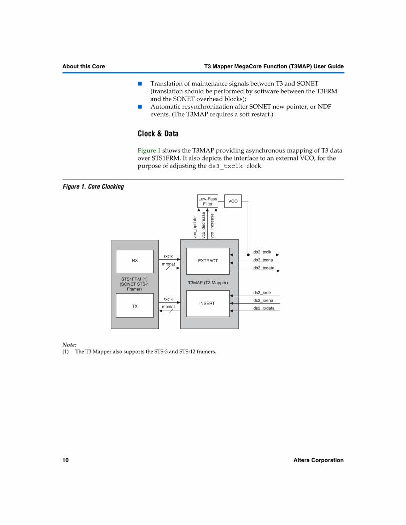
� Supports the standard T3 rate via adaptive control of the external VCO—illustrated in Figure 1. – The FIFO buffer is 32 bytes deep.
� Accepts data bytes from a SONET framer� Performs destuffing� Extracts a raw T3 bit stream, and forwards it optionally to a T3FRM
INSERT
� Performs asynchronous mapping� Uses a 32-byte FIFO buffer� Performs payload bit stuffing� Provides payload bytes to a SONET framer� Accepts a T3 bit stream that is either raw or from a T3FRM
Unsupported Features
The T3MAP does not support the following features:
� SONET/SDH line and path overhead processing;� T3 framing, including overhead processing;
Altera Corporation 9
About this Core T3 Mapper MegaCore Function (T3MAP) User Guide
� Translation of maintenance signals between T3 and SONET (translation should be performed by software between the T3FRM and the SONET overhead blocks);
� Automatic resynchronization after SONET new pointer, or NDF events. (The T3MAP requires a soft restart.)
Clock & Data
Figure 1 shows the T3MAP providing asynchronous mapping of T3 data over STS1FRM. It also depicts the interface to an external VCO, for the purpose of adjusting the ds3_txclk clock.
Figure 1. Core Clocking
Note:(1) The T3 Mapper also supports the STS-3 and STS-12 framers.
VCO
ds3_txclk
INSERT
T3MAP (T3 Mapper)
EXTRACT
ds3_txdata
ds3_rxclk
ds3_rxdata
vco_
decr
ease
vco_
incr
ease
STS1FRM (1)(SONET STS-1
Framer)
Low-PassFilter
RX
TX
rxclk
mrxdat
txclk
mtxdatINSERT
ds3_txena
ds3_rxena
vco_
upda
te
10 Altera Corporation

Getting Started
User Guide
Getting Started
22
Getting Started
This section describes how to obtain a variant from the T3 Mapper MegaCore® Function (T3MAP). It explains how to install the T3MAP on your PC, and walks you through the process of implementing the variant in a design.
You can test-drive a T3MAP using the Altera® OpenCore® feature—within the Quartus® II software—to instantiate it, to perform place-and-route, to perform static timing analysis, and to simulate it using a third-party simulator, within your custom logic. You only need licenses when you are ready to generate programming files.
Design Walkthrough
This design walkthrough involves the following steps:
1. Obtaining and installing the T3MAP MegaCore Function.
2. Generating a custom T3MAP for your system using the Altera MegaWizard® Plug-In.
3. Implementing the rest of your system using AHDL, VHDL, or Verilog HDL.
4. Simulating the T3MAP within your design.
5. Synthesis, compilation, and place-and-route.
6. Licensing the T3MAP to configure the device.
7. Performing post-routing simulation.
The instructions assume that:
� You are using a PC � You are familiar with the Quartus II software.� The Quartus II software (the newest version) is installed in the default
location.� You are using the OpenCore feature to test-drive a T3MAP, or you
have licensed it.
Altera Corporation 11
Getting Started T3 Mapper MegaCore Function (T3MAP) User Guide
Obtaining & Installing the T3MAP
To start using the T3MAP, you need to obtain the MegaCore package, which includes the following:
� Data sheet� User guide� AIRbus, and Midbus interface functional specifications� MegaWizard Plug-In
– Encrypted gate level netlist– Place-and-route constraints (where necessary)– Secure RTL simulation model
� Demo testbench� Access to problem reporting system
Downloading the MegaCore Function
If you have Internet access, you can download the T3 Mapper MegaCore function from the Altera web site. Follow the instructions below to obtain the core via the Internet. If you do not have Internet access, you can obtain the core from your local Altera representative.
1. Point your web browser at http://www.altera.com/IPmegastore.
2. In the IP MegaSearch keyword field type T3.
3. Click the link for the T3 Mapper MegaCore function.
4. On the product page, click the Free Test-Drive icon.
5. Follow the on-line instructions to download the function and save it to your hard disk.
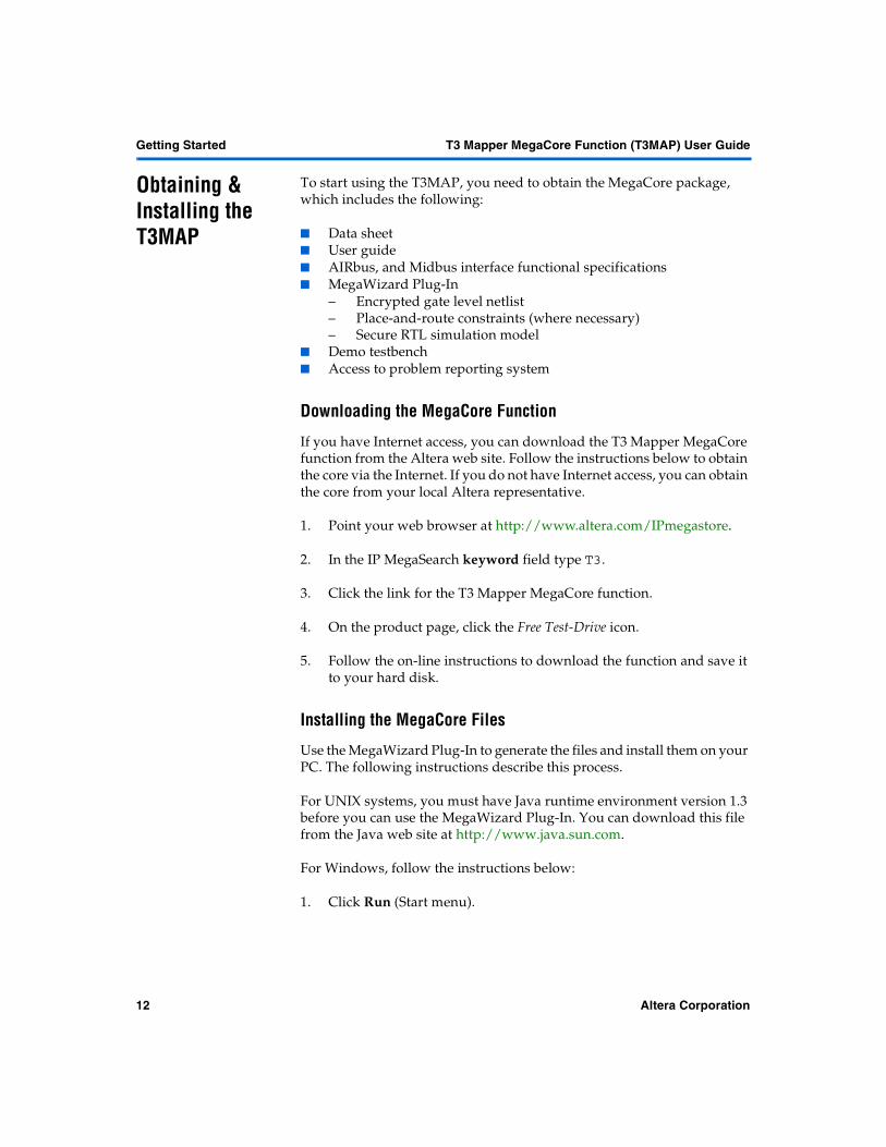
Installing the MegaCore Files
Use the MegaWizard Plug-In to generate the files and install them on your PC. The following instructions describe this process.
For UNIX systems, you must have Java runtime environment version 1.3 before you can use the MegaWizard Plug-In. You can download this file from the Java web site at http://www.java.sun.com.
For Windows, follow the instructions below:
1. Click Run (Start menu).
12 Altera Corporation
T3 Mapper MegaCore Function (T3MAP) User Guide GettingGetting Started
2
Getting Started
2. Type <path name>\<filename>.exe, where <path name> is the location of the downloaded T3MAP and <filename> is the filename of the T3MAP. Click OK.
3. The MegaCore Installer dialog box appears. Follow the MegaWizard Plug-In instructions to finish the installation.
4. If you do not have the Quartus II software version 1.1 or higher, you must specify the directory—in which you installed the files—as a user library. Search for “User Libraries” in Quartus II Help for instructions on how to add these libraries.
Generating a Custom T3MAP
This section describes the design flow using the T3 Mapper MegaCore function and the Quartus II development system. A MegaWizard Plug-In is provided with the T3MAP. The MegaWizard Plug-In Manager—used within the Quartus II software—allows you to create or modify design files to meet the needs of your application. You can then instantiate the T3MAP in your design file.
To create a custom T3MAP using the MegaWizard Plug-In, follow these steps:
1. Start the MegaWizard Plug-In by choosing the MegaWizard Plug-In Manager command (Tools menu) in the Quartus II software. The MegaWizard Plug-In Manager dialog box is displayed.
� Refer to Quartus II Help for detailed instructions on how to use the MegaWizard Plug-In Manager.
2. Specify that you want to create a new custom variant and click Next.
3. On the second page of the MegaWizard Plug-In, open the Communications folder, and select the T3MAP from the T3 folder.
4. Choose the type of output files (language), specify the folder and name for the files the MegaWizard Plug-In creates, and click Next.
5. Select the optional parameters and choices that you require.
6. The final screen lists the design files created by the MegaWizard Plug-In, and indicates the location of the simulation models for the selected variant. Click Finish.
Altera Corporation 13
Getting Started T3 Mapper MegaCore Function (T3MAP) User Guide
Implementing the System
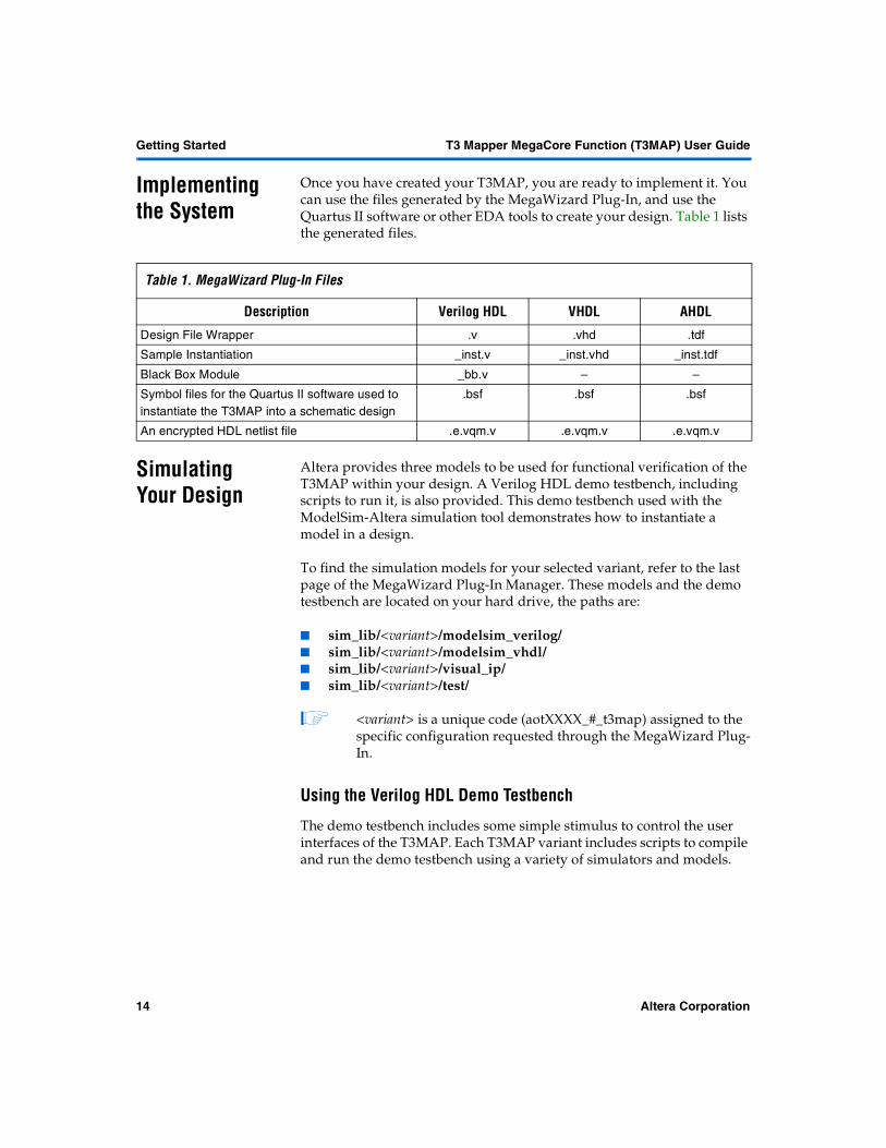
Once you have created your T3MAP, you are ready to implement it. You can use the files generated by the MegaWizard Plug-In, and use the Quartus II software or other EDA tools to create your design. Table 1 lists the generated files.
Simulating Your Design
Altera provides three models to be used for functional verification of the T3MAP within your design. A Verilog HDL demo testbench, including scripts to run it, is also provided. This demo testbench used with the ModelSim-Altera simulation tool demonstrates how to instantiate a model in a design.
To find the simulation models for your selected variant, refer to the last page of the MegaWizard Plug-In Manager. These models and the demo testbench are located on your hard drive, the paths are:
� sim_lib/<variant>/modelsim_verilog/� sim_lib/<variant>/modelsim_vhdl/� sim_lib/<variant>/visual_ip/ � sim_lib/<variant>/test/
� <variant> is a unique code (aotXXXX_#_t3map) assigned to the specific configuration requested through the MegaWizard Plug-In.
Using the Verilog HDL Demo Testbench
The demo testbench includes some simple stimulus to control the user interfaces of the T3MAP. Each T3MAP variant includes scripts to compile and run the demo testbench using a variety of simulators and models.
Table 1. MegaWizard Plug-In Files
Description Verilog HDL VHDL AHDL
Design File Wrapper .v .vhd .tdf
Sample Instantiation _inst.v _inst.vhd _inst.tdf
Black Box Module _bb.v – –
Symbol files for the Quartus II software used to instantiate the T3MAP into a schematic design
.bsf .bsf .bsf
An encrypted HDL netlist file .e.vqm.v .e.vqm.v .e.vqm.v
14 Altera Corporation
T3 Mapper MegaCore Function (T3MAP) User Guide GettingGetting Started
2
Getting Started
Using the Visual IP Software
The Visual IP software facilitates the use of Visual IP simulation models with third-party simulation tools. To view a simulation model, you must have the Visual IP software installed on your system. To download the software, or for instructions on how to use the software, refer to the Altera web site at http://www.altera.com, and search for Visual IP. For examples of how to use the provided Visual IP model, refer to the sample scripts included with the demo testbench.
Synthesis, Compilation & Place & Route
After you have verified that your design is functionally correct, you are ready to perform synthesis and place-and-route. Synthesis can be performed by the Quartus II development tool, or by a third-party synthesis tool. The Quartus II software works seamlessly with tools from many EDA vendors, including Cadence, Exemplar Logic, Mentor Graphics, Synopsys, Synplicity, and Viewlogic.
Using Third-Party EDA Tools for Synthesis
To synthesize your design in a third-party EDA tool, follow these steps:
1. Create your custom design instantiating a T3MAP.
2. Synthesize the design using your third-party EDA tool. Your EDA tool should treat the T3MAP instantiation as a black box by either setting attributes or ignoring the instantiation.
3. After compilation, generate a netlist file in your third-party EDA tool.
Using the Quartus II Development Tool for Compilation & Place-and-Route
To use the Quartus II software to compile and place-and-route your design, follow these steps:
1. Select Compile mode (Processing menu).
2. Specify the compiler settings in the Compiler Settings dialog box (Processing menu) or use the Compiler Settings wizard.
3. If you are not using the Quartus II software version 1.1 or higher, you must specify the user libraries for the project and the order in which the compiler searches the libraries.
Altera Corporation 15

Getting Started T3 Mapper MegaCore Function (T3MAP) User Guide
4. Specify the input settings for the project. Choose EDA Tool Settings (Project menu). Select Custom EDIF in the Design entry/synthesis tool list. Click Settings. In the EDA Tool Input Settings dialog box, make sure that the relevant tool name or option is selected in the Design Entry/Synthesis Tool list.
5. Add your third-party EDA tool-generated netlist file to your project.
6. Add any .tdf, .vhd, or .v files not synthesized in the third-party tool.
7. Add the pre-synthesized and encrypted .e.vqm.v file from your working directory, created by the MegaWizard Plug-In Manager.
8. Constrain your design as required.
9. Compile your design. The Quartus II compiler synthesizes and performs place-and-route on your design.
� Refer to Quartus II Help for further instructions on performing compilation.
Licensing for Configuration
After you have compiled and analyzed your design, you are ready to configure your targeted Altera PLD. If you are evaluating the T3MAP with the OpenCore feature, you must license the function before you can generate programming files. To obtain licenses contact your local Altera sales representative.
� All current T3MAP variants use a single license, with ordering code: PLSM-T3MAP.
Performing Post-Routing Simulation
After you have licensed the T3MAP, you can generate EDIF, VHDL, Verilog HDL, and Standard Delay Output Files from the Quartus II software and use them with your existing EDA tools to perform functional modeling and post-routing simulation of your design.
1. Open your existing Quartus II project.
2. Depending on the type of output file you want, specify Verilog HDL output settings or VHDL output settings in the General Settings dialog box (Project menu).
3. Compile your design with the Quartus II software, refer to the “Using the Quartus II Development Tool for Compilation & Place-and-Route”section. The Quartus II software generates output and programing files.
16 Altera Corporation
T3 Mapper MegaCore Function (T3MAP) User Guide GettingGetting Started
2
Getting Started
4. You can now import your Quartus II software-generated output files (.edo, .vho, .vo, or .sdo) into your third-party EDA tool for post-route, device-level, and system-level simulation.
Altera Corporation 17

Notes:
Specifications
User Guide
Specifications
3
The T3 Mapper MegaCore® Function (T3MAP) uses the MegaWizard® Plug-In—within the Quartus®II software to generate variants in VHDL, AHDL, or Verilog HDL, which you can instantiate into your design.
Table 1 shows the optional features available for the T3MAP.
Note(1) The numbers for logic elements (LEs) and embedded system blocks (ESBs) are approximate as of October 2001.
Users are strongly advised to run the MegaWizard Plug-In and Quartus II software to see exact numbers for the T3MAP.
Functional Description
The T3MAP comprises two major blocks, EXTRACT and INSERT.
EXTRACT
T3 Data Rate
The T3MAP provides support of the standard T3 rates by maintaining adaptive control of an external VCO. In this case, a Phase Lock Loop (PLL) is formed using the FIFO buffer fill status as the phase comparator. The FIFO buffer stores extracted T3 data from the SONET SPE. The low-pass filter and VCO are external to the core. A software programmable threshold—either EXT_FIFO_HIGH or EXT_FIFO_LOW—will assert either vco_increase or vco_decrease when the number of bytes in the FIFO buffer is below or above those software registers. This indicates a change is required in the T3 clock rate, ds3_txclk. An additional signal vco_update is used to indicate that the value in either vco_decrease or vco_increase has changed.
� vco_decrease indicates the 32-byte FIFO buffer is emptying and the clock should decrease.
� vco_increase indicates the 32-byte FIFO buffer is filling and the clock should increase.
Table 1. Optional Features Note (1)
Options Parameters Choices LEs ESBs
Basic Configuration – – 1,017 2
Altera Corporation 19

Specifications T3 Mapper MegaCore Function (T3MAP) User Guide
� vco_update indicates a change in either vco_decrease or vco_increase.
Data Byte Acceptance
The T3MAP accepts data bytes from a SONET framer via a Midbus interface. See “Midbus Interface” on page 23 for more details.
Destuffing
The destuffing mechanism compensates for the frequency differences between the SONET and T3 data paths.
T3 Extraction
The T3MAP extracts a T3 bit stream from the input SONET SPE. The T3MAP is also capable of forwarding the T3 bit stream to a T3FRM (optional). The EXTRACT block extracts the two overhead communications bits from the SPE and stores them in a register (EXT_OH). The EXTRACT block synchronizes with the Midbus when the EXTRACT software enable (CTRL_ENABLE) register is asserted. Synchronization status, for the EXTRACT block, is kept in the EXT_STAT register.
INSERT
T3 Bit Acceptance
The T3MAP accepts a raw T3 bit stream, or takes T3 data from the T3FRM with the overhead intact (optional).
Asynchronous Mapping
In order to generate an output conforming to T3-SPE mapping, the INSERT block takes data from an internal 32-byte deep FIFO buffer containing T3 data collected from the T3 Mapper interface.
The INSERT block also inserts the two software programmable overhead communication bits (INS_OH) into the SPE payload where designated by the T3-SPE standard. The INSERT block synchronizes with the Midbus when the INSERT software enable (CTRL_ENABLE) register is asserted. Synchronization status of the INSERT block is kept in the INS_STAT register.
20 Altera Corporation
T3 Mapper MegaCore Function (T3MAP) User Guide GettingSpecifications
Specifications
3
Stuffing
The T3MAP bit stuffing mechanism compensates for the frequency differences between T3 and SONET data. The T3MAP also handles SONET positive and negative stuffing. This stuffing action is performed in the SONET network to compensate for frequency differences within the SONET network.
SONET positive/negative stuffing, and T3MAP stuffing mechanisms are independent of each other.
� A SONET NDF or new pointer event requires a soft restart of the T3MAP. To do a soft restart you need to toggle the INSERT block control enable register, “INS_CTRL - MAP_INSERT Control - 'h0” on page 29, and the EXTRACT clock control enable register, “EXT_CTRL - MAP_EXTRACT Control - 'h5” on page 30. The NDF state is not detected by the T3MAP, but it reflects a major movement in the position of the mapped data in the SONET stream requiring the T3MAP to resynchronize itself to the payload.
Altera Corporation 21
Specifications T3 Mapper MegaCore Function (T3MAP) User Guide
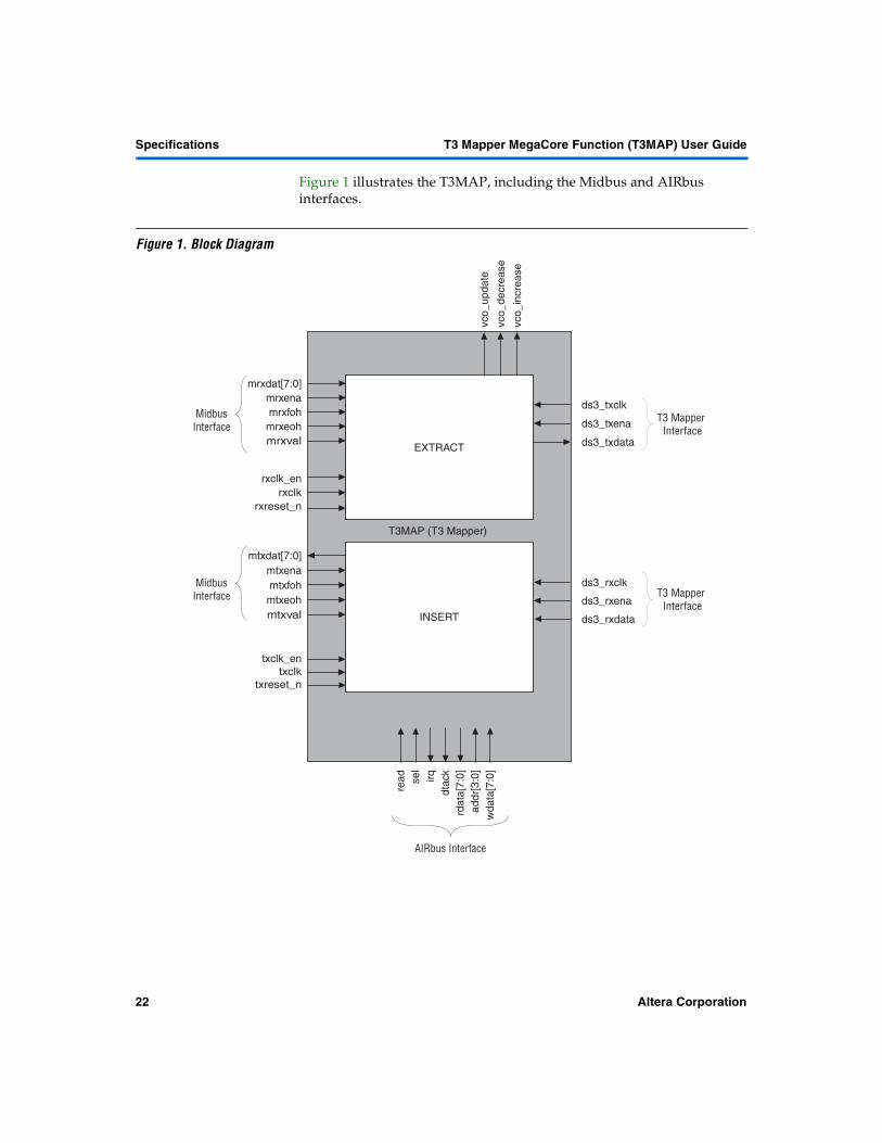
Figure 1 illustrates the T3MAP, including the Midbus and AIRbus interfaces.
Figure 1. Block Diagram
sel
read
addr
[3:0
]w
data
[7:0
]
rdat
a[7:
0]irq
AIRbus Interface
vco_
incr
ease
vco_
decr
ease
mtxdat[7:0]mtxena
mrxdat[7:0]mrxena
ds3_rxdata
ds3_rxclk
ds3_txdataEXTRACT
ds3_txclkMidbus
Interface
txclktxreset_n
INSERT
rxclkrxreset_n
dtac
k
T3 Mapper Interface
T3 Mapper Interface
MidbusInterface
T3MAP (T3 Mapper)
mrxeohmrxfoh
mtxeohmtxfoh
mrxval
mtxval
txclk_en
rxclk_en
ds3_txena
ds3_rxena
vco_
upda
te
22 Altera Corporation

T3 Mapper MegaCore Function (T3MAP) User Guide GettingSpecifications
Specifications
3
Interfaces & Protocols
Three interfaces support the T3MAP: the middle interface (Midbus), the access to internal registers (AIRbus) interface, and the T3 mapper interface. These interfaces are illustrated in Figure 1.
Midbus Interface
The Midbus interface is a simple synchronous full-duplex data path bus. The T3MAP Midbus transports data over a single-byte lane in each direction. The required frequency of the Midbus varies depending on the SONET framer supported—see Table 2.
Note:(1) In the case of higher bandwidth interfaces, the signals, txclk_en and rxclk_en,
are used to match the data rate with the clock rate. This column shows the expected nominal duty cycle of the enable signal.
In the receive direction (RX), the data is transferred from the Midbus master to the slave (T3MAP). In the transmit direction (TX), data is transferred from the slave (T3MAP) to the Midbus master. In each direction the Midbus can carry eight bits per clock cycle. It includes midbus receive data (mrxdat[7:0]) and midbus receive enable (mrxena) lines to indicate a valid data transfer in the RX direction, and midbus transmit data (mtxdat[7:0]) and midbus transmit enable (mtxena) lines to indicate a valid data request in the TX direction.
Receive Direction
Figure 2 shows the Midbus signals for the T3MAP interfacing to an STS-1 framer, in the receive direction. The T3MAP reads data on mrxdat, on the rising edge of rxclk. The following position indicators are also presented with the data.
� mrxval indicates that the following strobes are valid, see Figure 2.– mrxena indicates mrxdat is user payload (PL)– mrxfoh indicates mrxdat is a fixed frame overhead (A1, A2, J0,
Z0, B1, E1, F1) this includes all section and line overhead, and undefined/growth.
Table 2. Midbus Clocks
Configuration Clock Rate (MHz) Clock Nominal Enable Rate (1)(txclk_en or rxclk_en)
STS-1 6.48 Held active every clock
STS-1x3 19.44 Active: 1 in 3 clocks
STS-1x12 77.76 Active: 1 in 12 clocks
Altera Corporation 23

Specifications T3 Mapper MegaCore Function (T3MAP) User Guide
– mrxeoh indicates mrxdat is an embedded frame overhead (J1, B3) this includes all path overhead.
Figure 2. T3MAP Receive Midbus Timing Diagram
Transmit Direction
Figure 3 shows the Midbus signals for the T3MAP interfacing to an STS-1 framer, in the transmit direction. These signals provide position commands (listed below) that indicate the type of byte being processed on the next clock pulse.
� mtxval indicates that the following strobes are valid, see Figure 3.– mtxena indicates user payload– mtxfoh indicates a fixed frame overhead (A1, A2, J0, Z0, B1, E1,
F1) this includes all section and line overhead, and undefined/growth
– mtxeoh indicates an embedded frame overhead (J1, B3) this includes all path overhead
When enabled (INS_CTRL register) and synchronized (INS_STAT register) the T3MAP puts valid data on mtxdat on the rising edge of txclk, following an asserted high mtxval.
In accordance with the Midbus specification, if mtxval is deasserted, T3MAP sends out zeros on the mtxdat bus.
mrxclk
mrxval
mrxena
mrxdat
mrxfoh
mrxeoh
PL A1 A2 J0 J1 PL PL PL B1 E1 F1 B3
...
...
...
...
...
...
24 Altera Corporation

T3 Mapper MegaCore Function (T3MAP) User Guide GettingSpecifications
Specifications
3
Figure 3. T3MAP Transmit Midbus Timing Diagram
AIRbus Interface
The AIRbus interface provides access to internal registers using a simple synchronous internal processor bus protocol. This consists of separate read (rdata) and write (wdata) data buses, a data transfer acknowledge (dtack) signal, and a select (sel) signal. An address bus (addr[3:0]) and read (read) signal indicate the location and type of access within the block. The rdata buses and dtack signals can be merged from multiple blocks using a simple OR function. The dtack signal is sustained until the block sel is removed (four-way handshaking) meaning the AIRbus can cross clock domain boundaries. The T3MAP is an AIRbus slave with a data width of eight bits.
� The internal registers are run on the current Midbus clock. Thus, the EXTRACT side registers are run using rxclk (rxclk_en), and the INSERT side registers are run with txclk (txclk_en).
� For more detailed information on the Midbus and AIRbus refer to the Altera web site at http://www.altera.com.
T3 Mapper Interface
The T3 Mapper interface is used to convey full T3 data. The T3MAP also provides users with the option of receiving and transmitting framed T3 data from/to a T3 Framer. The DS3 bit stream, including overhead bits, is then mapped into a SONET framer SPE asynchronously.
mtxclk
mtxval
mtxena
mtxdat
mtxfoh
mtxeoh
PL PL 0 0A1 A2 J0 J1 PL PL B10 0 E1 F1 B3...
...
...
...
...
...
Altera Corporation 25

Specifications T3 Mapper MegaCore Function (T3MAP) User Guide
Receive
A new DS3 bit is expected to be present on the ds3_rxdata signal at the rising edge of ds3_rxclk—see Figure 4.
Figure 4. Receive T3 Mapper Timing Diagram
Transmit
A new DS3 bit is expected to be present on the ds3_txdata signal at the rising edge of ds3_txclk—see Figure 5.
Figure 5. Transmit T3 Mapper Timing Diagram
Performance Table 3 shows the required speed and estimated gate count of the T3MAP in an APEX 20KE device.
Notes:(1) All LE and ESB numbers are approximate as of October 2001.(2) If the T3MAP interfaces to an STS-12 line rate the fMAX will be 77.76 MHz.
clk
ena
rxdat
...
...X1 I1 I2 I3 I84 F1
clk
ena
txdat
...
...X1 I1 I2 I3 I84
Table 3. Performance Note (1)
LEs ESBs fMAX (MHz) (2)
1,017 2 44.784 required
26 Altera Corporation

T3 Mapper MegaCore Function (T3MAP) User Guide GettingSpecifications
Specifications
3
I/O Signals Table 4 lists the I/O signals for the T3MAP.
Table 4. I/O Signals (Part 1 of 2)
Port Direction Description
RX Signals
rxclk Input Receive data clock
rxclk_en Input Receive clock enable
rxreset_n Input Receive active low reset
TX Signals
txclk Input Transmit data clock
txclk_en Input Transmit clock enable
txreset_n Input Transmit active low reset
Midbus Signals
mrxdat[7:0] Input Midbus receive data
mrxena Input Midbus receive enable
mrxfoh Input Midbus receive fixed overhead
mrxeoh Input Midbus receive embedded overhead
mrxval Input Midbus receive valid data
mtxdat[7:0] Output Midbus transmit data
mtxena Input Midbus transmit enable
mtxfoh Input Midbus transmit fixed overhead
mtxeoh Input Midbus transmit embedded overhead
mtxval Input Midbus transmit valid data
AIRbus Signals
sel Input Select signal. When this signal goes high, it selects internal registers
read Input Read/write control signalHigh: Reads data from data busLow: Writes data to data bus
irq Output Interrupt request signal. When the signal is ‘1’, this indicates an interrupt request
dtack Output Data transfer acknowledge signal that comes from the internal registers to indicate the internal registers are ready to send or accept data
rdata[7:0] Output Read data signals from internal register
addr[3:0] Input Register address
wdata[7:0] Input Write data signals to internal register
T3 Mapper Interface Signals
ds3_rxclk Input T3 Mapper Interface receive clock at 44.736 MHz
Altera Corporation 27
Specifications T3 Mapper MegaCore Function (T3MAP) User Guide
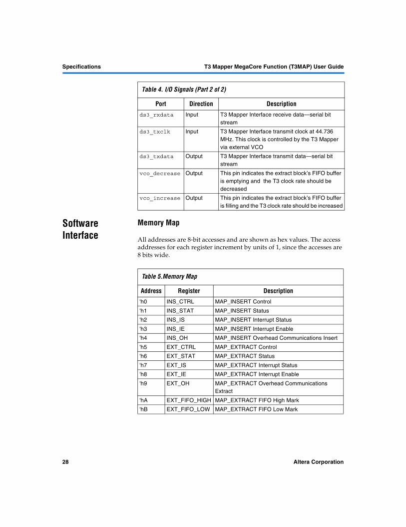
Software Interface
Memory Map
All addresses are 8-bit accesses and are shown as hex values. The access addresses for each register increment by units of 1, since the accesses are 8 bits wide.
ds3_rxdata Input T3 Mapper Interface receive data—serial bit stream
ds3_txclk Input T3 Mapper Interface transmit clock at 44.736 MHz. This clock is controlled by the T3 Mapper via external VCO
ds3_txdata Output T3 Mapper Interface transmit data—serial bit stream
vco_decrease Output This pin indicates the extract block’s FIFO buffer is emptying and the T3 clock rate should be decreased
vco_increase Output This pin indicates the extract block’s FIFO buffer is filling and the T3 clock rate should be increased
Table 4. I/O Signals (Part 2 of 2)
Port Direction Description
Table 5.Memory Map
Address Register Description
'h0 INS_CTRL MAP_INSERT Control 'h1 INS_STAT MAP_INSERT Status 'h2 INS_IS MAP_INSERT Interrupt Status 'h3 INS_IE MAP_INSERT Interrupt Enable 'h4 INS_OH MAP_INSERT Overhead Communications Insert 'h5 EXT_CTRL MAP_EXTRACT Control 'h6 EXT_STAT MAP_EXTRACT Status 'h7 EXT_IS MAP_EXTRACT Interrupt Status 'h8 EXT_IE MAP_EXTRACT Interrupt Enable 'h9 EXT_OH MAP_EXTRACT Overhead Communications
Extract 'hA EXT_FIFO_HIGH MAP_EXTRACT FIFO High Mark 'hB EXT_FIFO_LOW MAP_EXTRACT FIFO Low Mark
28 Altera Corporation

T3 Mapper MegaCore Function (T3MAP) User Guide GettingSpecifications
Specifications
3
Registers
The following is a list of access codes used to describe the type of register bits.
INSERT Block Register Description
Table 6.Register Bit Description
Code Description
RW Read/Write RO Read-Only RW1C Read/Write 1 to Clear RW0S Read/Write 0 to Set RTC Read to Clear RTS Read to Set RTCW Read to Clear/Write RTSW Read to Set/Write RWTC Read/Write any value to Clear RWTS Read/Write any value to Set RWSC Read/Write Self-Clearing RWSS Read/Write Self-Setting UR0 Unused bits/Read as 0 UR1 Unused bits/Read as 1
Table 7.INS_CTRL - MAP_INSERT Control - 'h0
Field Bits Access Function Default ENABLE 0 RW When '0', MAP_INSERT produces static undefined output
('b1111 1111). Initially after rising edge MAP_INSERT will synchronize to mtxefp, then produce valid output.
0
Table 8.INS_STAT - MAP_INSERT Status - 'h1
Field Bits Access Function Default MAP_SYNC 0 RO When asserted, the T3MAP has been synchronized to the
mtxeoh pulse.0
Altera Corporation 29
Specifications T3 Mapper MegaCore Function (T3MAP) User Guide
EXTRACT Block Register Description
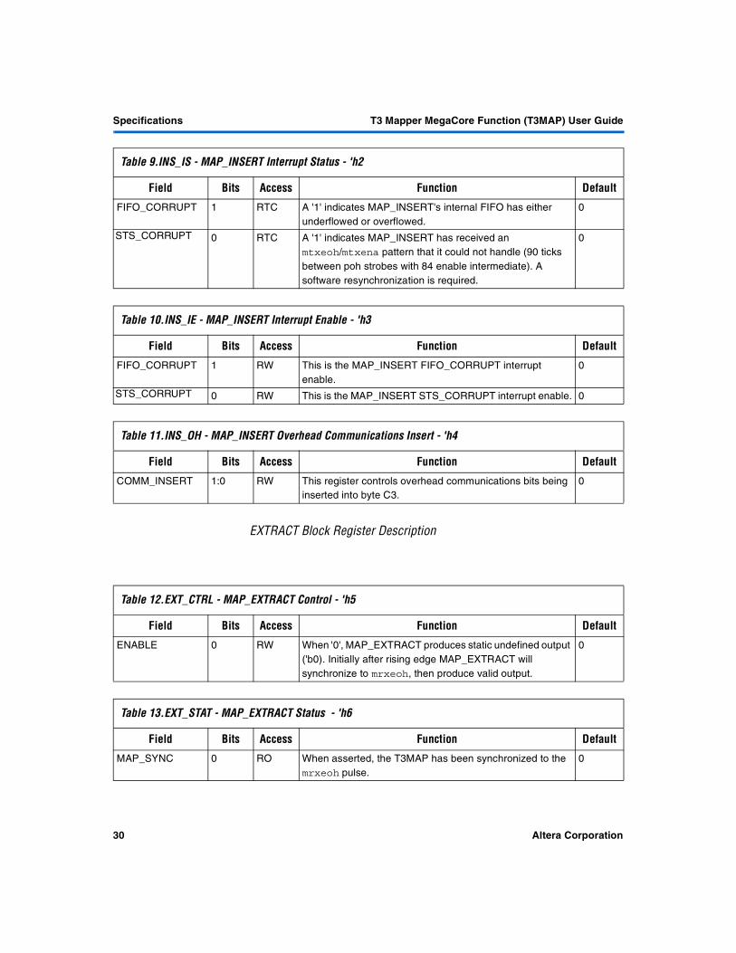
Table 9.INS_IS - MAP_INSERT Interrupt Status - 'h2
Field Bits Access Function Default FIFO_CORRUPT 1 RTC A '1' indicates MAP_INSERT's internal FIFO has either
underflowed or overflowed.0
STS_CORRUPT 0 RTC A '1' indicates MAP_INSERT has received an mtxeoh/mtxena pattern that it could not handle (90 ticks between poh strobes with 84 enable intermediate). A software resynchronization is required.
0
Table 10.INS_IE - MAP_INSERT Interrupt Enable - 'h3
Field Bits Access Function Default FIFO_CORRUPT 1 RW This is the MAP_INSERT FIFO_CORRUPT interrupt
enable.0
STS_CORRUPT 0 RW This is the MAP_INSERT STS_CORRUPT interrupt enable. 0
Table 11.INS_OH - MAP_INSERT Overhead Communications Insert - 'h4
Field Bits Access Function Default COMM_INSERT 1:0 RW This register controls overhead communications bits being
inserted into byte C3.0
Table 12.EXT_CTRL - MAP_EXTRACT Control - 'h5
Field Bits Access Function Default ENABLE 0 RW When '0', MAP_EXTRACT produces static undefined output
('b0). Initially after rising edge MAP_EXTRACT will synchronize to mrxeoh, then produce valid output.
0
Table 13.EXT_STAT - MAP_EXTRACT Status - 'h6
Field Bits Access Function Default MAP_SYNC 0 RO When asserted, the T3MAP has been synchronized to the
mrxeoh pulse.0
30 Altera Corporation
T3 Mapper MegaCore Function (T3MAP) User Guide GettingSpecifications
Specifications
3
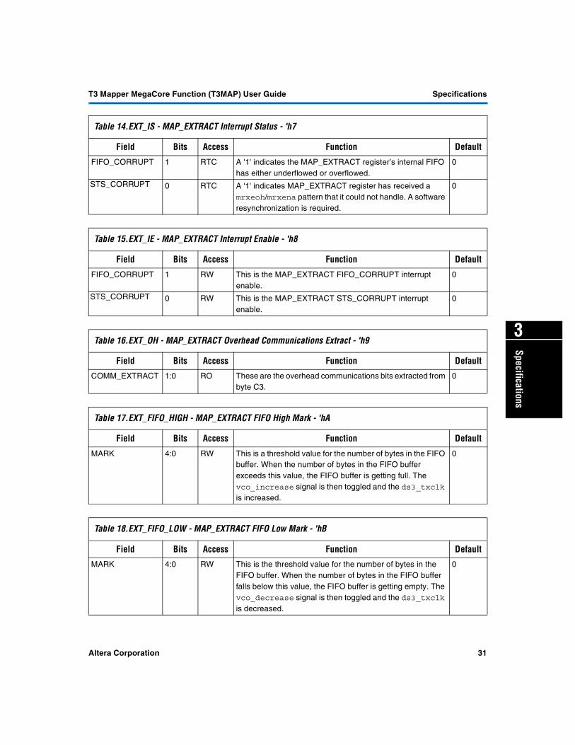
Table 14.EXT_IS - MAP_EXTRACT Interrupt Status - 'h7
Field Bits Access Function Default FIFO_CORRUPT 1 RTC A '1' indicates the MAP_EXTRACT register’s internal FIFO
has either underflowed or overflowed.0
STS_CORRUPT 0 RTC A '1' indicates MAP_EXTRACT register has received a mrxeoh/mrxena pattern that it could not handle. A software resynchronization is required.
0
Table 15.EXT_IE - MAP_EXTRACT Interrupt Enable - 'h8
Field Bits Access Function Default FIFO_CORRUPT 1 RW This is the MAP_EXTRACT FIFO_CORRUPT interrupt
enable.0
STS_CORRUPT 0 RW This is the MAP_EXTRACT STS_CORRUPT interrupt enable.
0
Table 16.EXT_OH - MAP_EXTRACT Overhead Communications Extract - 'h9
Field Bits Access Function Default COMM_EXTRACT 1:0 RO These are the overhead communications bits extracted from
byte C3.0
Table 17.EXT_FIFO_HIGH - MAP_EXTRACT FIFO High Mark - 'hA
Field Bits Access Function Default MARK 4:0 RW This is a threshold value for the number of bytes in the FIFO
buffer. When the number of bytes in the FIFO buffer exceeds this value, the FIFO buffer is getting full. The vco_increase signal is then toggled and the ds3_txclk is increased.
0
Table 18.EXT_FIFO_LOW - MAP_EXTRACT FIFO Low Mark - 'hB
Field Bits Access Function Default MARK 4:0 RW This is the threshold value for the number of bytes in the
FIFO buffer. When the number of bytes in the FIFO buffer falls below this value, the FIFO buffer is getting empty. The vco_decrease signal is then toggled and the ds3_txclk is decreased.
0
Altera Corporation 31

Notes: