T2S Non Functional Tests v. 1 - European Central Bank
69
T2S Non Functional Tests Business Continuity Test Cases Description Author 4CB Version 1.8 Date 27-05-2013 Status Final Draft Classification PUBLIC
Transcript of T2S Non Functional Tests v. 1 - European Central Bank

T2S Non Functional Tests
Business Continuity Test Cases Description
Author 4CB
Version 1.8
Date 27-05-2013
Status Final Draft
Classification PUBLIC

BUSINESS CONTINUITY TEST CASES DESCRIPTION
Page 2 of 16
T2S Non Functional Tests
1. INTRODUCTION: BUSINESS CONTINUITY 4
2. PRIMARY SITE FAILURE TEST CASE DESCRIPTION 6
2.1. TEST OBJECTIVE .............................................................................................................. 6
2.1.1. TEST OBJECTIVE DESCRIPTION ............................................................................................................... 6 2.1.2. EXPECTED RESULTS ............................................................................................................................ 6
2.2. TEST CONDITIONS ........................................................................................................... 6
2.3. TEST CASE DESCRIPTION ................................................................................................... 7
2.3.1. COMPONENTS INVOLVED ...................................................................................................................... 7
2.4. TEST CASE PREPARATION .................................................................................................. 7
2.4.1. INFRASTRUCTURE PREPARATION ............................................................................................................. 7 2.4.2. DATA INJECTION ................................................................................................................................ 8
2.5. EXECUTION ..................................................................................................................... 8
2.6. REPORTING .................................................................................................................... 9
2.6.1. MEASUREMENT TOOLS ......................................................................................................................... 9 2.6.2. TEST CASE REPORT DESCRIPTION ............................................................................................................ 9
3. DESCRIPTION OF REGION 3 PRIMARY SITE FAILURE TEST CASE 10
3.1. TEST OBJECTIVE ............................................................................................................ 10
3.1.1. TEST DESCRIPTION ........................................................................................................................... 10 3.1.2. EXPECTED RESULTS .......................................................................................................................... 10
3.2. TEST CONDITIONS ......................................................................................................... 10
3.3. TEST CASE DESCRIPTION ................................................................................................. 11
3.3.1. COMPONENTS INVOLVED .................................................................................................................... 11
3.4. TEST CASE PREPARATION ................................................................................................ 12
3.4.1. INFRASTRUCTURE PREPARATION ........................................................................................................... 12
3.5. EXECUTION ................................................................................................................... 12
3.6. REPORTING .................................................................................................................. 12
3.6.1. MEASUREMENT TOOLS ....................................................................................................................... 12 3.6.2. TEST CASE REPORT DESCRIPTION .......................................................................................................... 12
4. DESCRIPTION OF REGIONAL DISASTER TEST CASE 13
4.1. TEST OBJECTIVE ............................................................................................................ 13
4.1.1. TEST OBJECTIVE DESCRIPTION ............................................................................................................. 13 4.1.2. EXPECTED RESULTS .......................................................................................................................... 13
4.2. TEST CONDITIONS ......................................................................................................... 13
4.3. TEST CASE DESCRIPTION ................................................................................................. 14
4.3.1. COMPONENTS INVOLVED .................................................................................................................... 14
BUSINESS CONTINUITY TEST CASES DESCRIPTION
Page 3 of 16
T2S Non Functional Tests
4.4. TEST CASE PREPARATION ................................................................................................ 14
4.4.1. INFRASTRUCTURE PREPARATION ........................................................................................................... 14 4.4.2. DATA INJECTION .............................................................................................................................. 15
4.5. EXECUTION ................................................................................................................... 15
4.6. REPORTING .................................................................................................................. 16
4.6.1. MEASUREMENT TOOLS ....................................................................................................................... 16 4.6.2. TEST CASE REPORT DESCRIPTION .......................................................................................................... 16

BUSINESS CONTINUITY TEST CASES DESCRIPTION
Page 4 of 16
T2S Non Functional Tests
1. Introduction: Business Continuity
The objective of the business continuity tests is to prove that ability of T2S to meet the agreed service
levels even in case of severe incidents, intra-region and inter-region failovers.
Along the lines of the “T2S on T2” principle, the business continuity solution for T2S will replicate
what is already in place for SSP. Consequently for T2S, three types of service interruptions have been
considered:
Short continuity failure is understood as a short service interruption (e.g. due to
component failures, a system reboot, or a line failure). These kind of problems are solved by
usage of redundant and reliable infrastructures: in such a case a fault on a single component
has no impact on service availability.
Primary site failure is understood as a serious service interruption (e.g. disruptions caused
by fire, flood, terrorist attack or major hardware/telecommunications faults) that makes
primary site unavailable. These events require the activation of an alternative regional site.
Regional disaster is understood as a "wide-scale regional disruption" causing severe
permanent interruption of transportation, telecommunication, power or other critical
infrastructure components across a metropolitan or geographical area and its adjacent
communities (resulting in a wide-scale evacuation or inaccessibility of the population within
the normal commuting range of the disruption's origin). These events require the activation of
an alternative region. In addition, the active-active configuration, implies that, in case of a
main failure in one region, T2 and T2S production environments will be hosted in the same
region. In such case (in order to distribute and balance the workload), each of the two
surviving sites will run one of the two PROD environments (T2 and T2S) as reported in the
picture below.
Loss of data and loss of uptime are the two business drivers that serve as baseline requirements for a
Service Continuity solution. When quantified, they are more formally known as Recovery Point
Objective (RPO) and Recovery Time Objective (RTO) respectively:
The RPO is a point of consistency to which a user wants to recover or restart. It is measured
as the amount of time between the moment when the point of consistency was created or
captured and that when the failure occurred;
The RTO is the maximum amount of time required for recovery or restart to a specified point
of consistency.
The architecture of T2S core system (Region 1 And Region 2) is based on the concept “2 regions / 4
sites”. The four sites are fully equivalent and each of them is equipped with the same technical
resources: processor, storage, network interface, software, etc. Usage of parallel synchronous and

BUSINESS CONTINUITY TEST CASES DESCRIPTION
Page 5 of 16
T2S Non Functional Tests
asynchronous data replication sessions features for both disk and tape subsystem will make available
consistent copies of data in each site. So in case of disaster occurrences it will be possible to restart all
services in one of the available site without the need to start full resynchronization and assuring
consistency and data loss within the target RPO parameters.
T2S goals for the 3 scenarios are:
Short continuity failure RTO=0 ; RPO=0 ;
Primary Site Failure: RTO≤1h ; RPO=0 ;
Regional disaster: RTO≤2h; RPO ≤ 2 minutes.
As the Legal Archiving and provision of statistical reports are less business critical than the other T2S
components, the service continuity model follows the “1 region/2 sites” schema, i.e. Legal Archiving
and provision of statistical reports run in any case in Region 3 allowing to manage short continuity
failure and major failure:
Short continuity failure: RTO≤2h; RPO=0;
Primary Site Failure: RTO≤24h; RPO=0;
In both cases short continuity failure refers to the capacity of the system to comply with the “never
stop the production” principle.
This requirements is addressed at infrastructure level by redundant hardware and software clustering
solutions to avoids any single points of failure. In addition, in case of fault of hardware or software
component, solution of the problem will be guarantee according to SLA specified in Annex IV (SLA) –
Chapter IV.4 Service Support –p22-25).
For such reasons, short continuity failure won’t be included in the Business Continuity NFT.
In the following chapter, primary site failure and regional disaster scenario will be described: these
scenarios cover all the disaster scenario condition foreseen in the T2S Business Continuity Framework.

BUSINESS CONTINUITY TEST CASES DESCRIPTION
Page 6 of 16
T2S Non Functional Tests
2. Primary Site Failure Test Case Description
2.1. Test objective
2.1.1. Test objective description
Primary site A failure is understood as a serious service interruption (e.g. disruptions caused by fire,
flood, terrorist attack or major hardware/telecommunications faults) that make primary site
unavailable.
These events require the activation of an alternative regional site.
Primary Site failure scenario implies no data loss independently from disaster scenarios.
It means that all systems have to be able to restart on the secondary site and that at the same time
the storage infrastructure has to be able to assure data consistency and data protection using
Synchronous and Asynchronous replication features.
Objective of this test is to verify the full procedure of the failover phase: in this phase the
environments will moved on the secondary site and data protection will be assured by the
asynchronous replication features only.
It has to be mentioned that parallel primary site failure on both region is a not covered scenario by
T2S Business Continuity framework. Such kind of disaster scenario will need manual interaction and
per-case decisions
2.1.2. Expected Results
Primary Site A failure test is focused on verify that T2S infrastructure will be able to restart on
secondary site after a disaster that make unavailable the primary site.
The expected results for this test are to:
Verify that the full procedure (including restart of T2S core services) can take a maximum of 1
hour (RTO≤1hour);
Verify that all elaborating systems will be able to restart on secondary site using consistent
data and without data loss (RPO=0);
Start incremental asynchronous resynchronization between site B and site C (without the need
of a full copy);
Restart all systems on site B without waiting for end of resynchronization between site B and
site C;
Restart of all the auxiliary systems (STS …).
2.2. Test Conditions
The test will involve the T2S production environment (both zOS and Open systems active) and will be
mainly focused on storage disk infrastructure.
More in detail the disaster will be simulated making unavailable the primary storage subsystem in
primary site while producing I/O on z/OS and open systems1.
1 The way to make unavailable the disk subsystems will be defined before the execution of the test depending on the cross correlation with the
other T2 and T2S environment

BUSINESS CONTINUITY TEST CASES DESCRIPTION
Page 7 of 16
T2S Non Functional Tests
Inter-Region Connectivity
4CBNET
Intra-Region Connectivity
Intra-Region Connectivity
Asynchronous re
plicatio
n
SITE A SITE B
SITE C SITE D
Adaptive replication
PROD
environment
Golden Copy
2.3. Test case description
2.3.1. Components Involved
The following component will be involved for the test:
T2S Production environment
Disk subsystems active in the primary region (for disaster simulation)
SAN infrastructure (for disaster simulation)
Disk subsystems active in the secondary and third site (for failover phase)
External networks (for the failover phase)
2.4. Test case preparation
2.4.1. Infrastructure preparation
Full storage disk infrastructure has to be active and running for the T2S environments involved in the
test.
So for such environment the following copy sessions have to be active at the same time:
Synchronous Replication between site A and Site B;
Asynchronous Replication between site B and Site C;
Adaptive Replication between Site C and Site D;
Golden copy active on site C.

BUSINESS CONTINUITY TEST CASES DESCRIPTION
Page 8 of 16
T2S Non Functional Tests
Inter-Region Connectivity
4CBNET
Intra-Region Connectivity
Intra-Region Connectivity
As
yn
ch
ron
ou
s r
ep
lic
ati
on
SITE A SITE B
SITE C SITE D
Synchronous replication
Adaptive replication
PROD
environment
Golden Copy
Region 1
Region 2
2.4.2. Data injection
zOS and Open system for environment involved in the test have to produce I/O on z/OS simulating
normal operational condition before starting the test.
2.5. Execution
Test execution will be divided in the following phases:
Disaster simulation:
o Disk subsystem access on the primary site will be make unavailable
Failover phase execution:
o This phase will include the following steps :
Verify that no data are lost and check where the most updated data are
located (site B or site C);
Configure volumes on site B as primary;
Start incremental asynchronous resynchronization between site B and site C
(in case more updated data are located on site C rescue data from site C
without the need to involve a full copy or a change in session synchronization
direction);
Restart all systems on site B without waiting for end of resynchronization
between site B and site C.
The committed RTO and RPO will be verified referring to this phase (disaster
simulation is outside of RTO and RPO verification).
End to end tests execution
This phase is aimed at checking the regular behaviour of T2S in recovery conditions

BUSINESS CONTINUITY TEST CASES DESCRIPTION
Page 9 of 16
T2S Non Functional Tests
2.6. Reporting
2.6.1. Measurement Tools
No measurement tools are needed for RTO; the RPO will be checked using storage infrastructure
utilities.
2.6.2. Test case report description
Case ID BC_PSA_01
Involved environment Report here the involved zOS and Open
systems involved
Disaster recovery simulation model How the primary disk subsystems is make
unavailable
Time duration RTO it must be less than or equal to 1 hour
Checked RPO it must be equal zero
Incremental asynchronous resynch between site B and
site C? It must be Yes
Are systems able to restart B without waiting for end of resynchronization between site B and site C?
It must be Yes

BUSINESS CONTINUITY TEST CASES DESCRIPTION
Page 10 of 16
T2S Non Functional Tests
3. Description of Region 3 Primary Site Failure Test Case
3.1. Test objective
3.1.1. Test description
The Region 3 primary (active) site (E) failure is understood as a major service interruption (e.g.
disruptions caused by fire, flood, terrorist attack or major hardware/telecommunications faults) that
makes the Region 3 primary site unavailable.
This major failure on the active site (case of an unplanned need) requires the activation of the switch
mechanism to reopen the service in the Region 3 recovery site (F).
The Region 3 primary site (E) failure scenario implies no data loss independently from the nature of
the disaster.
The primary and recovery production environments are both up and running at the same time, but
only one is “active” for the production activity. The switch mechanism consists in activating the
relevant scheduling batch chain on the respective platform (ACTIVE chain, STAND-BY chain).
All systems have to be able to restart on the Region 3 recovery site. At the same time, the storage
infrastructure has to be able to assure data consistency and data protection using asynchronous
replication features.
In this context, updates in databases, limited to Business Intelligence repository (new user created,
new ad-hoc queries), Business Intelligence logs related to users’s activity can be lost.
As far as “business data” are only updated during the night processing (datawarehouse loading), the
primary and secondary databases have the same content and are not impacted by a switch during
production.
The objective of this test is to verify the full switch procedure.
3.1.2. Expected Results
The Region 3 primary site (E) failure test is focused on verifying that the T2S LTSI infrastructure will
be able to restart on the Region 3 recovery site after a major disaster that makes the Region 3
primary site unavailable.
The expected results for this test are to:
Verify that the switch procedure can take a maximum of 24 hours (RTO≤24hours);
Verify that all systems will be able to restart on the Region 3 recovery site using consistent
data and without data loss (RPO=0);
3.2. Test Conditions
Refer to the T2S Region 3 LTSI Logical Design for softwares and hardwares configuration.
BUSINESS CONTINUITY TEST CASES DESCRIPTION
Page 11 of 16
T2S Non Functional Tests
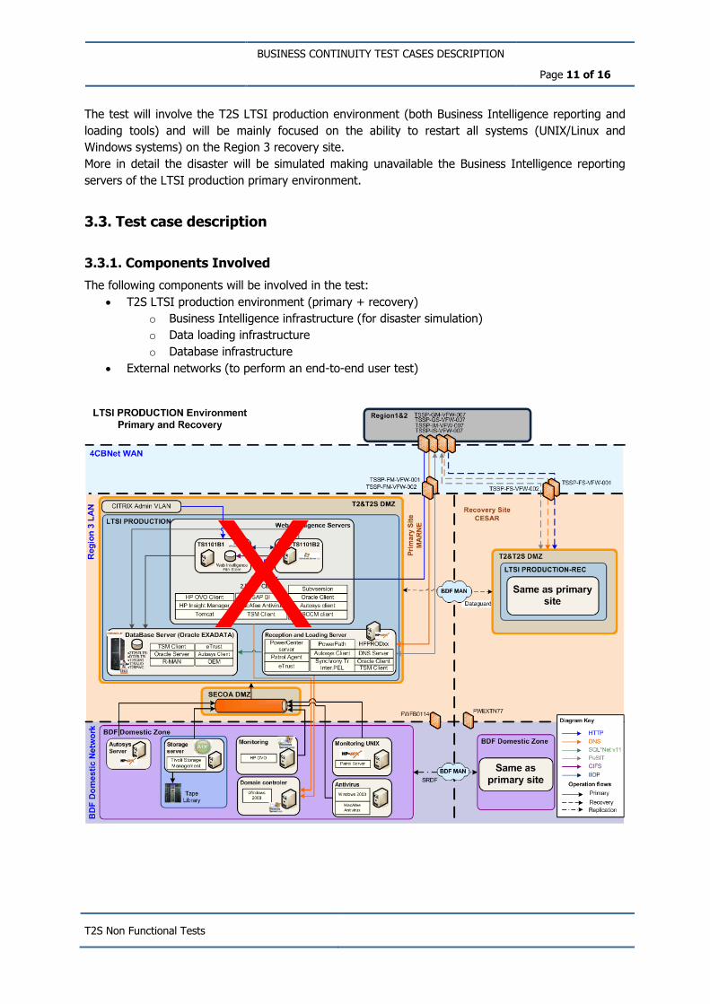
The test will involve the T2S LTSI production environment (both Business Intelligence reporting and
loading tools) and will be mainly focused on the ability to restart all systems (UNIX/Linux and
Windows systems) on the Region 3 recovery site.
More in detail the disaster will be simulated making unavailable the Business Intelligence reporting
servers of the LTSI production primary environment.
3.3. Test case description
3.3.1. Components Involved
The following components will be involved in the test:
T2S LTSI production environment (primary + recovery)
o Business Intelligence infrastructure (for disaster simulation)
o Data loading infrastructure
o Database infrastructure
External networks (to perform an end-to-end user test)
X
BUSINESS CONTINUITY TEST CASES DESCRIPTION
Page 12 of 16
T2S Non Functional Tests
3.4. Test case preparation
3.4.1. Infrastructure preparation
The full LTSI infrastructure on the primary site has to be active and running for the T2S LTSI
environments involved in the test.
UNIX/Linux and Windows systems for the Region 3 primary environment involved in the test have to
simulate normal operational condition before starting the test.
3.5. Execution
Test execution will be divided in two phases:
Phase n°1: major disaster simulation
o Business Intelligence reporting servers on the Region 3 primary site will be made
unavailable.
Phase n°2: switch procedure execution
o This phase will include the following steps:
Verify that no data is lost; (As a reminder, “business data” are only updated
during the night processing (datawarehouse loading), the primary and
secondary databases have the same content and are not impacted by a
switch during production.)
Restart all systems on the Region 3 recovery site (F);
The committed RTO and RPO will be verified referring to this phase (disaster
simulation is outside of RTO and RPO verification).
End-to-end user test execution
o This phase is aimed at checking the regular behavior of the T2S LTSI module in
recovery conditions.
3.6. Reporting
3.6.1. Measurement Tools
No measurement tools are needed for RTO. The RPO will be checked using the report issued by
Oracle Dataguard (Oracle recovery mechanism) after the daily asynchronous replication procedure
execution.
3.6.2. Test case report description
Case ID BC_PSE_01
Involved environment Report here the involved UNIX/Linux and
Windows systems involved
Disaster recovery simulation model How the primary Business Intelligence reporting
servers are made unavailable
Time duration RTO It must be less than or equal to 24 hours
Checked RPO It must be equal to zero
Are all systems able to restart in the Region 3 recovery site (F)?
It must be Yes
BUSINESS CONTINUITY TEST CASES DESCRIPTION
Page 13 of 16
T2S Non Functional Tests
4. Description of Regional Disaster Test Case
4.1. Test objective
4.1.1. Test objective description
Regional disaster is understood as a "wide-scale regional disruption" causing severe permanent
interruption of transportation, telecommunication, power or other critical infrastructure components
across a metropolitan or geographical area and its adjacent communities (resulting in a wide-scale
evacuation or inaccessibility of the population within the normal commuting range of the disruption's
origin).
These events require the activation of an alternative region.
Due to the active-active configuration of the two Regions (hosting T2 and T2S production
environments), occurrence of a regional disaster implies that T2 and T2S production environments will
be hosted in the same region. In such a case (in order to distribute and balance the workload), each
of the two surviving sites will run one of the two PROD environments (T2 and T2S)
Objective of this test is to verify the full procedure of the failover phase2: in this phase the
environments will be moved on the secondary site of the surviving region and data protection will be
assured by the synchronous replication features only.
4.1.2. Expected Results
Regional disaster test is focused on verifying that T2S will be able to restart on the secondary site of
the surviving region after a disaster that make unavailable the primary region.
Expected result for this test are :
verify that the full procedure (including restart of T2S core services) can take a maximum of 2
hour (RTO<=2 hours);
verify that all elaborating systems will be able to restart using consistent data and with a
maximum data loss of two minutes (RPO<=2 minutes);
start incremental resynch between the secondary site and the primary site (without the need
of a full copy);
restart of all the auxiliary systems (STS, …).
4.2. Test Conditions
The test will involve the T2S production environment (both zOS and Open systems active) and will be
mainly focused on storage disk infrastructure.
More in detail, the disaster will be simulated making unavailable storage connectivity between the two
regions while producing I/O on z/OS and open systems3.
2 The possible inclusion of technical measures linked to the Restart After Disaster in the scope of the test will be evaluated once the discussion
on Restart After Disaster procedures will be finalized.
3 The way to make unavailable the storage connectivity between the two regions will be defined before the execution of the test depending on the cross correlation with the other T2 and T2S environments.

BUSINESS CONTINUITY TEST CASES DESCRIPTION
Page 14 of 16
T2S Non Functional Tests
Inter-Region Connectivity
4CBNET
Intra-Region Connectivity
Intra-Region Connectivity
SITE A SITE B
SITE C SITE D
Synchronous replication
Synchronous replication
PROD
environment
Region 1
Region 2
Golden Copy
4.3. Test case description
4.3.1. Components Involved
The following component will be involved for the test:
T2S Production environment
Disk subsystems active in the primary region (for disaster simulation)
SAN infrastructure (for disaster simulation)
Disk subsystems active in the secondary region (for failover phase)
External networks (for the failover phase)
4.4. Test case preparation
4.4.1. Infrastructure preparation
Full storage disk infrastructure has to be active and running for the T2S environments involved in the
test.
The following copy sessions have to be active at the same time:
Synchronous Replication between site A and Site B;
Asynchronous Replication between site B and Site C;
Adaptive Replication between Site C and Site D;
Golden copy active on site C.

BUSINESS CONTINUITY TEST CASES DESCRIPTION
Page 15 of 16
T2S Non Functional Tests
Inter-Region Connectivity
4CBNET
Intra-Region Connectivity
Intra-Region Connectivity
As
yn
ch
ron
ou
s r
ep
lic
ati
on
SITE A SITE B
SITE C SITE D
Synchronous replication
Adaptive replication
PROD
environment
Golden Copy
Region 1
Region 2
4.4.2. Data injection
zOS and Open system for environment involved in the test have to produce I/O on z/OS simulating
normal operational condition before starting the test.
4.5. Execution
Test execution will be splitted in two phases :
Disaster simulation
o Storage connectivity between the two sites will make unavailable avoiding real-time
asynchronous replication between the two regions.
Failover phase execution
o This phase will include the following steps :
Verify data consistency and time stamp at site C (timestamp will be used to
verify that RPO<=2 minutes);
Move Adaptive Replication from site C to site D in synchronous mode and wait
for complete alignment.
Change synchronous replication direction from site C to site D making primary
volumes on site D (as an alternative way: delete adaptive replication from site
C to site D and define a new synchronous replication session from site D to
site C avoiding any resynchronization).
Start applications on site D.
The committed RTO and RPO will be verified referring to this phase (disaster
simulation is outside of RTO and RPO verification).
End to end tests execution
This phase is aimed at checking the regular behaviour of T2S in recovery conditions

BUSINESS CONTINUITY TEST CASES DESCRIPTION
Page 16 of 16
T2S Non Functional Tests
4.6. Reporting
4.6.1. Measurement Tools
No measurement tools are needed for RTO; the RPO will be checked using storage infrastructure
utilities.
4.6.2. Test case report description
Case ID BC_RD_01
Involved environment Report here the involved zOS and Open
systems involved
Disaster recovery simulation model How storage connectivity between the two
regions is make unavailable
Time duration RTO it must be less than or equal to 2 hours
Checked RPO it must be less than or equal to 2 minutes
Incremental asynchronous resynch between site C and
site D ?
It must be Yes
T2S Non Functional Tests
Performance Test Case description
Author 4CB
Version 1.8
Date 27/05/2013
Status Final draft
Classification PUBLIC

Performance Test Case description
Page 2 of 45
T2S Non Functional Tests
I. INTRODUCTION 5
A. GENERAL INFORMATION ................................................................................................... 5
B. SOURCES OF DATA ........................................................................................................... 5
C. PERFORMANCE TESTS OBJECTIVES ...................................................................................... 6
D. BUSINESS DAY WORKLOAD DISTRIBUTION ......................................................................... 8
1. ASSUMPTIONS USED FOR WORKLOAD PROFILING ............................................................................................ 8 2. BUSINESS DAY WORKLOAD AND TRAFFIC PROFILE ........................................................................................... 9
II. TEST SCENARIOS 12
A. GENERAL INFORMATION .................................................................................................. 12
B. MISSING ASSUMPTIONS .................................................................................................. 12
C. SCENARIO 1 – NIGHT TIME.............................................................................................. 12
1. SCENARIO 1 DESCRIPTION .................................................................................................................... 12
D. SCENARIO 2 – DAY TIME FOR A2A ................................................................................... 15
1. SCENARIO 2 DESCRIPTION .................................................................................................................... 15
E. SCENARIO 3 – DAY TIME FOR U2A ................................................................................... 19
2. SCENARIO 3 DESCRIPTION .................................................................................................................... 19
F. SCENARIO 4 – END OF DAY .............................................................................................. 20
1. SCENARIO 4 DESCRIPTION .................................................................................................................... 20
III. TEST CASES OBJECTIVE 21
A. TEST CASE PERF_01 ...................................................................................................... 21
1. TEST OBJECTIVE – BUSINESS VALIDATION TIME .......................................................................................... 21
B. TEST CASE PERF_02 ...................................................................................................... 21
1. TEST OBJECTIVE – MATCHING TIME ........................................................................................................ 21
C. TEST CASE PERF_03 ...................................................................................................... 22
1. TEST OBJECTIVE – REAL-TIME SETTLEMENT TIME ........................................................................................ 22
D. TEST CASE PERF_04 ..................................................................................................... 22
1. TEST OBJECTIVE – BATCH SETTLEMENT THROUGHPUT ................................................................................... 22
E. TEST CASE PERF_05 ...................................................................................................... 23
1. TEST OBJECTIVE – SD PROCESSING TIME .................................................................................................. 23
F. TEST CASE PERF_06 ...................................................................................................... 24
1. TEST OBJECTIVE – A2A QUERY RESPONSE TIME – SIMPLE QUERIES ................................................................... 24
G. TEST CASE PERF_07 ..................................................................................................... 25
1. TEST OBJECTIVE – A2A QUERY RESPONSE TIME – COMPLEX QUERIES ................................................................ 25
H. TEST CASE PERF_08 ..................................................................................................... 25
Performance Test Case description
Page 3 of 45
T2S Non Functional Tests
1. TEST OBJECTIVE – A2A MESSAGE RESPONSE TIME ........................................................................................ 25
I. TEST CASE PERF_09 ...................................................................................................... 26
1. TEST OBJECTIVE – U2A RESPONSE TIME - SIMPLE QUERIES ............................................................................ 26
J. TEST CASE PERF_10 ...................................................................................................... 27
1. TEST OBJECTIVE – U2A RESPONSE TIME - COMPLEX QUERIES .......................................................................... 27
K. TEST CASE PERF_11...................................................................................................... 27
1. TEST OBJECTIVE - U2A RESPONSE TIME - OTHER REQUESTS ........................................................................... 27
L. TEST CASE PERF_12 ...................................................................................................... 28
1. TEST OBJECTIVE – FILE TRANSFER THROUGHPUT: INPUT ............................................................................... 28
M. TEST CASE PERF_13 ..................................................................................................... 28
1. TEST OBJECTIVE – THROUGHPUT: OUTPUT................................................................................................. 28
TEST CASES DESCRIPTION 29
A. TEST CONDITIONS ......................................................................................................... 29
1. SOFTWARE VERSION (INFRASTRUCTURE) ................................................................................................... 29 2. SOFTWARE VERSION (APPLICATION) ........................................................................................................ 29 3. HARDWARE CONFIGURATION ................................................................................................................. 29 4. COMPONENTS INVOLVED ...................................................................................................................... 29
B. EXECUTION .................................................................................................................. 29
1. ENVIRONMENT PREPARATION AND TEST EXECUTION ...................................................................................... 29
C. REPORTING .................................................................................................................. 30
1. TEST CASE REPORT DESCRIPTION ............................................................................................................ 30
NIGHT TIME SCENARIO DESCRIPTION 32
A. TEST SCENARIO PREPARATION ......................................................................................... 32
1. TEST DATA PREPARATION ..................................................................................................................... 32 2. MESSAGES LOADING AND INJECTION ........................................................................................................ 33
B. EXECUTION .................................................................................................................. 34
1. TEST DURATION ................................................................................................................................ 34
DAY TIME FOR A2A SCENARIO DESCRIPTION 35
A. TEST SCENARIO PREPARATION ......................................................................................... 35
1. TEST DATA PREPARATION ..................................................................................................................... 35 2. MESSAGES LOADING AND INJECTION ........................................................................................................ 36
B. EXECUTION .................................................................................................................. 37
1. TEST DURATION ................................................................................................................................ 37
DAY TIME FOR U2A SCENARIO DESCRIPTION 38
A. TEST SCENARIO PREPARATION ......................................................................................... 38

Performance Test Case description
Page 4 of 45
T2S Non Functional Tests
1. TEST DATA PREPARATION ..................................................................................................................... 38 2. MESSAGES LOADING AND INJECTION ........................................................................................................ 39
B. EXECUTION .................................................................................................................. 39
1. TEST DURATION ................................................................................................................................ 39
END OF DAY SCENARIO DESCRIPTION 40
A. TEST SCENARIO PREPARATION ......................................................................................... 40
1. TEST DATA PREPARATION ..................................................................................................................... 40 2. MESSAGES LOADING AND INJECTION ........................................................................................................ 40
B. EXECUTION .................................................................................................................. 40
1. TEST DURATION ................................................................................................................................ 40
IV. ANNEX 1 - GLOSSARY 41

Performance Test Case description
Introduction Page 5 of 45
T2S Non Functional Tests
I. Introduction
A. General information
This document describes the performance tests to be carried out by the 4CB in order to prove that the
T2S platform (including both infrastructure and applications) in its final configuration is able to fulfil
the performance requirements contained in the URD, the Framework Agreement – Schedule 6 – T2S
Service Level Agreement and GTD documents. As indicated in the FA Schedule 6 many KPIs will be
defined only at the end of the bedding down period, six months after the last wave migration. For the
test, target values have been defined by the technical team.
The main objective of the performance tests is to check that the T2S platform in its final production
configuration is compliant with the Framework Agreement – Schedule 6 – T2S Service Level
Agreement indicators (Business Validation Time, Matching time, Real-time Settlement time, Batch
Settlement throughput, Static data processing time, system response times) under the conditions
described in the URD and updated according the results of the T2S volumetric survey of 2012-11-021
in terms of average and peak workload.
The commitment of the 4CB is related to the workload (average/peak) outlined in the URD and
Framework Agreement – Schedule 6 – T2S Service Level Agreement: the 4CB will not guarantee the
performance of the production environment beyond those values. However, they will aim at
extrapolating the results of tests in order to predict how the platform could behave beyond the
contractual obligations.
The performance tests will cover all the test cases described in the following sections of this document
and will simulate the expected daily workload profiles for User-to-Application mode (U2A) and
Application-to-Application (A2A) interactions.
Meaningful performance tests can only be conducted with a reliable and agreed set of volumetric
assumptions and workload distribution over a business day; therefore the first part of this document
describes four scenarios to be used as a context for the tests execution and the relevant workload
assumptions to be made to properly configure each scenario.
The last section of the document provides the list of performance tests to be executed, the necessary
input parameters under the relevant scenario and the expected results.
B. Sources of Data
The data used in this documentation stem from different sources:
1 In case of values not covered by the survey, the volumes used in the internal 4CB sizing assumption are taken into account

Performance Test Case description
Introduction Page 6 of 45
T2S Non Functional Tests
D4CB Volumetric assumptions document
T2S Processing Volume Analysis document
Framework Agreement – Schedule 6 – T2S Service Level Agreement
C. Performance Tests objectives
The main objective of the performance tests is to verify that the T2S platform is able to handle the
estimated volume of transactions in the peak hour in terms of number of settlements and number of
concurrent interactive users in compliance with a defined response time.
All the non functional requirements related to performance that can be verified through testing are
expressed in the Schedule 6 of the T2S Framework Agreement document. The following table
provides a short list of the T2S performance expectations.
Indicator
Target values (expectation)
Business Validation Time 95% within 3 minutes, 100% within 9 minutes
Matching Time 95% within 2 minute, 100% within 5 minutes
Real-time Settlement Time 95% within 7 minutes, 100% within 20 minutes
Batch Settlement Throughput Min.80 instructions per second
Static Data processing time 95% in 5 seconds, 100% in 5 minutes
A2A simple Query response time 95% in 3 seconds, 100% in 120 seconds
A2A response time for complex Queries 95% in 120 seconds, 100% in 10 minutes
A2A message response time 95% in 5 seconds, 100% in 120 seconds
U2A response time for simple queries 95% in 3 seconds, 100% in 120 seconds
U2A response time for complex queries 95% in 120 seconds, 100% in 10 minutes
U2A response time for other requests 95% in 5 seconds, 100% in 120 seconds
File Throughput 4 Gigabytes per hour
Figure 1: T2S Performance Indicators
The exact target values can be calculated using the workload characteristics2 listed hereafter and
related to year 2016:
Definition Volume Comments
Annual volume of Settlement Transactions 151.410.946
2 The workload characteristics will be adapted if need be according with the Supplemental CSD Volume Questionnaire results.

Performance Test Case description
Introduction Page 7 of 45
T2S Non Functional Tests
Peak day work load 2.435.486 Peak day workload is calculated as the average daily volume multiplied by a peak load factor of 4,15 which is provided in most markets by the CSDs.
Peak night time work load 1.704.840
60% pre-matched
68% received via file
Peak day time work load 730.646
60% pre-matched
64% received via file
Night time peak hour work load 227.312
Day time peak hour work load 67.000
Number of concurrent U2A users in Region 1/2 300
Number of concurrent U2A users in Region 3 100
Maximum number of users of Region 3 670
Maximum U2A browsing requests per hour 20.000
Maximum A2A RT requests queries per hour 10.000
Figure 2: T2S workload characteristics
The test expected results as well as other performance indicators (CPU consumption, use of storage
etc.) shall be monitored closely during the test scenarios.
The volume of inbound settlement instructions for the business day phases is reported below.
Definition Volume
Annual volume of Input Settlement Instructions 302.821.892
Peak day workload of Inbound Settlement Instructions 4.870.972
Peak night time work load of Inbound Settlement Instructions
855.830
Peak EOD/SOD work load of Inbound Settlement Instructions
1.409.172
Peak day time work load of Inbound Settlement Instructions
2.605.970
Night time peak hour work load of Inbound Settlement Instructions
122.262
EOD/SOD peak hour work load of Inbound Settlement Instructions
940.584
Performance Test Case description
Introduction Page 8 of 45
T2S Non Functional Tests
Day time peak hour work load of Inbound Settlement Instructions
215.262
Figure 3 : Inbound Settlement Instructions
D. Business Day Workload Distribution
This chapter aims at establishing a model based on existing information, experience and best guess
how a workload distribution all over the day might look like and how the T2S platform might be used
by the CSDs.
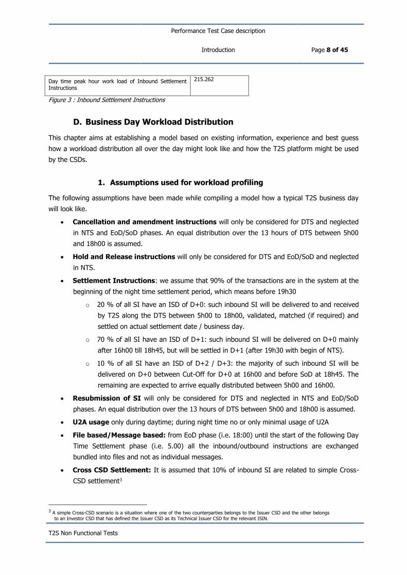
1. Assumptions used for workload profiling
The following assumptions have been made while compiling a model how a typical T2S business day
will look like.
Cancellation and amendment instructions will only be considered for DTS and neglected
in NTS and EoD/SoD phases. An equal distribution over the 13 hours of DTS between 5h00
and 18h00 is assumed.
Hold and Release instructions will only be considered for DTS and EoD/SoD and neglected
in NTS.
Settlement Instructions: we assume that 90% of the transactions are in the system at the
beginning of the night time settlement period, which means before 19h30
o 20 % of all SI have an ISD of D+0: such inbound SI will be delivered to and received
by T2S along the DTS between 5h00 to 18h00, validated, matched (if required) and
settled on actual settlement date / business day.
o 70 % of all SI have an ISD of D+1: such inbound SI will be delivered on D+0 mainly
after 16h00 till 18h45, but will be settled in D+1 (after 19h30 with begin of NTS).
o 10 % of all SI have an ISD of D+2 / D+3: the majority of such inbound SI will be
delivered on D+0 between Cut-Off for D+0 at 16h00 and before SoD at 18h45. The
remaining are expected to arrive equally distributed between 5h00 and 16h00.
Resubmission of SI will only be considered for DTS and neglected in NTS and EoD/SoD
phases. An equal distribution over the 13 hours of DTS between 5h00 and 18h00 is assumed.
U2A usage only during daytime; during night time no or only minimal usage of U2A
File based/Message based: from EoD phase (i.e. 18:00) until the start of the following Day
Time Settlement phase (i.e. 5.00) all the inbound/outbound instructions are exchanged
bundled into files and not as individual messages.
Cross CSD Settlement: It is assumed that 10% of inbound SI are related to simple Cross-
CSD settlement3
3 A simple Cross-CSD scenario is a situation where one of the two counterparties belongs to the Issuer CSD and the other belongs
to an Investor CSD that has defined the Issuer CSD as its Technical Issuer CSD for the relevant ISIN.

Performance Test Case description
Introduction Page 9 of 45
T2S Non Functional Tests
2. Business day workload and traffic profile
This section aims at providing an overview of the main activities and the workload connected for the
main domains and modules of the T2S application in a more detailed breakdown for the different
phases of the business day (DTS, EoD, SoD, NTS and MW period) and at providing the model of a
typical T2S business day in terms of incoming business traffic – either received as files or as message
- and subsequently the generated outgoing business traffic.
a. INTF domain:
i. During the DTS phase, the workload of Interface domain can be considered as medium
with no peak but the restart of the queued A2A request at the start of Real Time
Settlement phase (i.e. 5.00 A.M.). Both U2A and A2A requests are spread almost
continuously from 5.00 to 18.00.
ii. During the End of Day / Start of Day phase (18.00 – 19.30) the INTF domain is subject to
an high workload due to the sending of the EoD reports in push mode in addition to the
continuous U2A and A2A processing. Furthermore during the EoD phase, T2S receives the
updates to the list of eligible collateral and valuation prices between. Each Central Bank
will send its updates bundled in files, and not as individual messages.
iii. Throughout the Night Time Settlement Phase, the workload of the domain can be
considered as medium with some peaks due to the pushing of reports of the different
settlement sequences or the cash balance queries and to the release of queued A2A
requests during the different sequences.
b. LCMM domain:
i. According to the T2S Processing Volume Analysis document, the volume of Settlement
Instructions and Hold/Release instructions received during the Day Time Phase has a
peak from 16:00 to 18:00. The workload distribution for the Amendment and Cancellation
instructions and for the resubmission of the Settlement Instructions has a peak in the first
hours of the Day (i.e. from 5.00 to 10.00 ) in addition to the peak before the EoD cut-off.
The same profile can be applied for the workload due to the outbound Instructions.
ii. During the EoD/SoD phase the LCMM domain is heavily impacted by the revalidation
process of all the Settlement Instructions after the change of the business day
iii. During NTS, considering the assumption of having 90% of the Settlement Instructions
already present in the system, LCMM is subject to a low workload. This workload is mainly
due to the revalidation following possible Static Data updates and the validation of the
incoming Settlement Instructions
c. SETT domain:
i. The main task of the domain is the Standardisation and Preparation to Settlement (SPS)
running in continuous mode during the phase and the subsequent booking of SI having
ISD in the actual business day and the SI resubmitted after the NTS phase.

Performance Test Case description
Introduction Page 10 of 45
T2S Non Functional Tests
ii. During this phase no actual settlement is allowed nevertheless SETT domain is busy with
the valuation of securities positions in all eligible securities account for central bank/client
auto collateralisation and with the valuation of collateral eligible settlement instructions.
iii. The peak workload for SETT domain happens during the different sequences of NTS
cycles since we assumed that 90% of the Settlement Instructions will be in the system
before the 19:30 cut-off
d. LQMG domain:
i. During the DTS phase the LQMG has to process all the standing, timed and immediate
liquidity transfers from/to T2S Dedicated Cash Accounts with a medium workload that can
be considered stable throughout the phase apart from a small peak in the first hours.
ii. At the End of Day and at the Start of Day, LQMG will have a high workload executing the
liquidity transfers to sweep and fund the cash accounts in T2S.
iii. According to the T2S Processing Volume Analysis document, at the start of NTS, all the
inbound liquidity transfers submitted by the RTGS systems will be processed but since
these LTs have to be settled by the SETT domain, the workload of LQMG domain can be
neglected in this phase.
e. SDMG domain:
i. In a normal business day, the workload of SDMG during the DTS can be neglected.
Neverthless SDMG has to be in the position to manage the high load due to the issuance
of new Securities and the subsequent creation/update of the Security CSD Links or to the
mass update of Market-specific Attributes: according to the T2S Processing Volume
Analysis document such peak should happen between 16.00 and 19.00 (therefore
affecting also the EoD/SoD phase) with messages bundled into files.
ii. SDMG has to receive and process the daily valuation for all the eligible assets: T2S will
receive the updates to the list of eligible collateral and valuation prices between 17:30
and 19:00. Each Central Bank will send its updates bundled in files, and not as individual
messages. Such process is the peak workload for the domain during the business day.
iii. The workload for SDMG during the NTS can be neglected since it is limited to a small
number of maintenance requests.
f. SQRA domain:
i. The workload related to Reports can be neglected during the DTS while the number of
U2A and A2A queries can be considered stable during the phase.
ii. During the EoD/SoD, SQRA has to produce large volume reports for Securities positions,
pending instructions, Cash postings and Statement of Securities for End of month
reconciliation
iii. At the end of each night-time sequence, T2S generates full or delta reports as per the
report configuration setup of the relevant T2S Actors. Furthermore T2S processes any

Performance Test Case description
Introduction Page 11 of 45
T2S Non Functional Tests
instruction query received and validated during a settlement cycle run with a query
response back to the relevant T2S Actor.

Performance Test Case description
Test Scenarios Page 12 of 45
T2S Non Functional Tests
II. Test Scenarios
a. General information
On the basis of the T2S operational business day and the business day workload distribution analysis
performed in the previous paragraphs, four scenarios have been developed to serve as a significant
context to the different test cases:
Scenario 1 – Night time
Scenario 2 – Day time for A2A
Scenario 3 – Day time for U2A
Scenario 4 – End of Day
In addition to the specific assumptions made for each scenario as detailed in the following
paragraphs, the test environment will be pre-loaded with a set of data (both Static and Dynamic)
sufficient to simulate the workload on the different T2S components in live environment. In particular
the physical database tables will be populated with the number of rows required to generate the same
access path to the data expected during the live operation at the end of the migration period.
b. Missing assumptions
In T2S each CSD and NCB is allowed to set up restriction types in order to adapt the settlement
behaviour of the T2S platform. An indication how broadly this feature will be used is at the moment
still missing. Since a huge number of restriction types may also lead to performance issues this figure
needs yet to be clarified.
A specific test case on the MSA will be added in Q4 2013, before the start of the Non Functional test
phase.
c. Scenario 1 – Night time
1. Scenario 1 Description
During the night time phase 3.409.680 instructions shall be settled as peak volume (70% of daily
workload). In order to test the performance of the system during the night this number shall be used
as a starting point.

Performance Test Case description
Test Scenarios Page 13 of 45
T2S Non Functional Tests
The concrete breakdown of instructions in terms of matched/unmatched or file-based/message-based
transactions shall be performed as shown in the table below:
Name % # Message # File #
SI volume for NTS 3.409.680
Prematched 60% 2.045.808 10,00% 184.123 90,00% 1.861.685
Unmatched 40% 1.363.872 75,00% 920.614 25,00% 443.258 Figure 4: Settlement Instructions processed during Night Time
Furthermore the files received during the night time are divided into Large (LF), Medium (MF) and
Small (SF) having the following characteristics:
LF = 40% of all Msg sent as part of files are sent as Large Files containing 4000 single msg each;
MF = 40% of all Msg sent as part of files are sent as Medium Files containing 1000 single msg each;
SF = 20% of all Msg sent as part of files are sent as Small Files containing 100 single msg each
Any incoming instruction leads to the creation of a bunch of outgoing messages in order to inform the
sending party, the counterparty and the involved parties (CSDs and NCB´s) about the status of the
instruction. The following messages have to be created and therefore considered for the performance
tests:

Performance Test Case description
Test Scenarios Page 14 of 45
T2S Non Functional Tests
Outbound messages
Name % # Messages # Files #
T2S Outbound Business Response
Notification for Acceptance of Settlement Instruction 10% 34.097 90% 30.687 10% 3.410
Notification for Match Confirmation of Settlement Instruction 100% 136.387 90% 122.748 10% 13.639
Notification for Settlement or Fail 120% 4.091.616 15% 613.742 85% 3.477.874
Allegement 10% 13.639 100% 13.639 0% 0
Allegement Removal or Cancellation 10% 13.639 100% 13.639 0% 0
Notification of Cash Posting 100% 3.409.680 0% 0 3.409.680
Notification related to AutoColl process?
T2S Outbound Business Response Copies
Notification for Acceptance of Settlement Instruction 50% 170.484 90% 153.436 10% 17.048
Notification for Match Confirmation of Settlement Instruction 50% 68.194 90% 61.374 10% 6.819
Notification for Settlement or Fail 60% 2.045.808 25% 511.452 75% 1.534.356 Figure 5: Night Time Outbound messages

Performance Test Case description
Test Scenarios Page 15 of 45
T2S Non Functional Tests
Another point to be considered is the volume distribution among the different instruction types, since
the system workload differs. The following table shows the expected distribution and shall also be
used within the performance tests:
# NTS1 NTS2
80,00% 20,00%
SI volume for NTS 3.409.680 2.727.744 681.936
NTS 10,00% 340.968 272.774 68.194
DTS 90,00% 3.068.712 2.454.970 613.742
Corporate Actions 4,11% 140.138 5,14% 140.138 0%
FOP 22,37% 762.784 27,96% 762.784 0%
Other Transactions (mainly DVP) 73,52% 2.506.758 66,90% 1.824.822 100% 681.936 Figure 6: Instructions distribution for NTS1 and NTS2
During night-time as well as during day-time we expect a peak volume of 10.000 A2A requests per
hour The types of requests shall be distributed as follow:
A2A Querie / hour 10000
Securities settlement instruction queries 45,00% 4500
Securities account position queries 20,00% 2000
Cash related queries 25,00% 2500
SD Queries 10,00% 1000 Figure 7: A2A Queries peak hour volume distribution.
d. Scenario 2 – Day time for A2A
1. Scenario 2 Description
During the day phase 2.605.970 of Settlement instructions shall be handled as peak volume. In order
to test the performance of the system during the day time this number shall be used as a starting
point.
The distribution in terms of different instructions types shall be as follows:
Instruction life cicle
Name % # Message # Files #
SI Day Time peak day 2.605.970
SI Peak Hour during Day Time 446.668

Performance Test Case description
Test Scenarios Page 16 of 45
T2S Non Functional Tests
Prematched 60,00% 268.001 10% 26.800 90% 241.201
Unmatched 40,00% 178.667 75% 134.000 25% 44.667
Hold/Release of Settlement Instructions 35,00% 156.334 25% 39.083 75% 117.250
Amendment of SI 0,50% 2.233 100% 2.233
Cancellation of SI 1,50% 6.700 100% 6.700
Resubmission of Rejected Instructions 0,50% 2.233 90% 2.010 10% 223
Matched 30,00% 670 90% 603 10% 67
Unmatched 70,00% 1563 90% 1407 10% 156 Figure 8: Day time inbound instructions profile
Any incoming instruction leads to the creation of a bunch of outgoing messages in order to inform the
sending party, the counterparty and the involved parties (CSDs and NCB´s) about the status of the
instruction. The following messages have to be created and therefore considered for the performance
tests:

Performance Test Case description
Test Scenarios Page 17 of 45
T2S Non Functional Tests
Outbound messages
Name % # Messages # Files #
Inbound SI peak hour 446.668
Peak Hour T2S Outbound Business Response
Notification for Acceptance of Settlement Instruction 10 44.667 90% 40.200 10% 4.467
Notification for Match Confirmation of Settlement Instruction 100% 178.667 90% 160.800 10% 17.867
Notification for Settlement or Fail 120% 160.800 15% 24.120 85% 136.680
Notification for Acceptance of Amendment of Settlement Instruction 10% 927 100% 927 0% 0
Notification for Execution of Amendment of Settlement Instruction 100% 9.267 100% 9.267 0% 0
Notification for Acceptance of Hold/Release of Settlement Instruction including COSD 10% 15.633 90% 14.070 10% 1.563
Notification for Execution of Hold/Release of Settlement Instruction including COSD 100% 156.334 90% 140.701 10% 15.633
Allegement 25% 44.667 25% 11.167 75% 33.500
Allegement Removal or Cancellation 100% 44.667 90% 40.200 10% 4.467
Notification of Cash Posting 80% 357.334 5% 17.867 95% 339.468
Peak Hour T2S Outbound Business Response Copies
Notification for Acceptance of Settlement Instruction 50% 223.334 90% 201.001 10% 22.333
Notification for Match Confirmation of Settlement Instruction 50% 89.334 90% 80.400 10% 8.933
Notification for Settlement or Fail 60% 80.400 25% 20.100 75% 60.300
Notification for Acceptance of Amendment of Settlement Instruction 0% 0% 0 0% 0
Notification for Execution of Amendment of Settlement Instruction 50% 4.633 100% 4.633 0% 0
Notification for Acceptance of Hold/Release of Settlement Instruction including COSD 0% 0% 0 0% 0
Notification for Execution of Hold/Release of Settlement Instruction including COSD 1% 1.563 100% 1.563 0% 0
Performance Test Case description
Test Scenarios Page 18 of 45
T2S Non Functional Tests
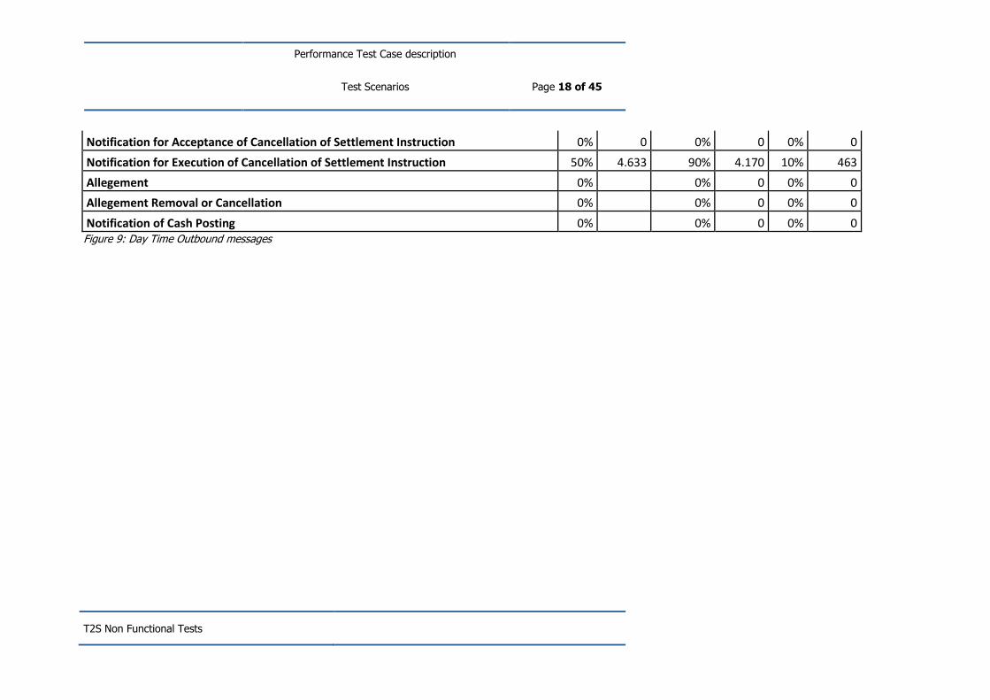
Notification for Acceptance of Cancellation of Settlement Instruction 0% 0 0% 0 0% 0
Notification for Execution of Cancellation of Settlement Instruction 50% 4.633 90% 4.170 10% 463
Allegement 0% 0% 0 0% 0
Allegement Removal or Cancellation 0% 0% 0 0% 0
Notification of Cash Posting 0% 0% 0 0% 0 Figure 9: Day Time Outbound messages

Performance Test Case description
Test Scenarios Page 19 of 45
T2S Non Functional Tests
Since this scenario is used also to measure the expected results related to Static Data Processing, the
workload of SD component must be taken into account. The peak hour composition of SD
maintenance instruction is the following one according to the T2S Processing Volume Analysis
document:
A2A SD maintenance instructions/hour 55850
Party maintenance instruction 2000
T2S Dedicated Cash Account maintenance instruction 150
Securities maintenance instruction 25000
Security CSD Link instruction 28700
During night-time as well as during day-time we expect a peak volume of 10.000 A2A requests per
hour. The types of requests shall be distributed as follow:
A2A Querie / hour 10000
Securities settlement instruction queries 45,00% 4500
Securities account position queries 20,00% 2000
Cash related queries 25,00% 2500
SD Queries 10,00% 1000 Figure 10: A2A Queries peak hour volume distribution.
e. Scenario 3 – Day time for U2A
2. Scenario 3 Description
We expect 20000 U2A queries per hour and 3.750 U2A updates. The different types of queries4 and
updates shall be distributed as follows:
U2A Queries/hour 20000
Securities settlement instruction queries 45% 9000
Securities account position queries 20% 4000
Cash related quesries 25% 5000
SD Queries 10% 2000 Figure 11 : U2A Queries volume distribution.
4 According to Framework Agreement – Schedule 6, “Simple queries and complex queries are those referenced as such within the User Detailed Functional Specifications (UDFS)”
Performance Test Case description
Test Scenarios Page 20 of 45
T2S Non Functional Tests
f. Scenario 4 – End of Day
1. Scenario 4 Description
During the End-of-day processing three major events have to be performed:
EoD processing
Generation of reports
Static Data loading
During the EoD processing data for the next business day will be loaded by the modules to revalidate
all the pending or incoming transactions during SOD, to prepare the templates for collateralisation
functionalities and for conditional settlement.
Furthermore the data sets for auto collateralisation and close link checks have to be loaded into the
system. The data are provided in a decentralised way by external systems (i.e. all the collateral
management systems of CBs and payment banks offering collateralisation services to their clients).
These data define collateral eligible securities as well as the reference prices and close links.
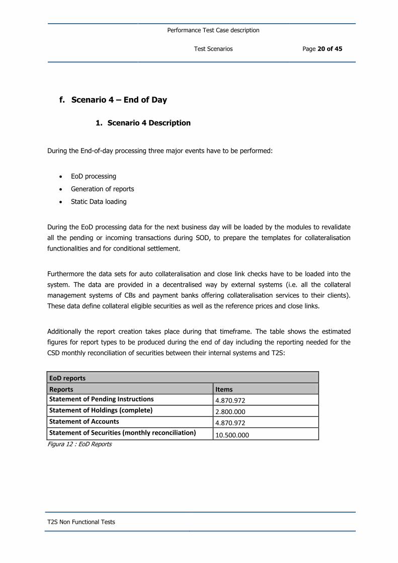
Additionally the report creation takes place during that timeframe. The table shows the estimated
figures for report types to be produced during the end of day including the reporting needed for the
CSD monthly reconciliation of securities between their internal systems and T2S:
EoD reports
Reports Items
Statement of Pending Instructions 4.870.972
Statement of Holdings (complete) 2.800.000
Statement of Accounts 4.870.972
Statement of Securities (monthly reconciliation) 10.500.000 Figura 12 : EoD Reports

Performance Test Case description
Test Cases Objective Page 21 of 45
T2S Non Functional Tests
III. Test Cases Objective
A. Test Case Perf_01
1. Test objective – Business Validation Time
a) Test description
The objective of the test is to verify that Business Validation Time is compliant with the expected
value indicated in the Framework Agreement – Schedule 6 – T2s Service Level Agreement.
Business validation time is the time that elapses between the reception of an instruction by T2S and
the end of the business validation process (i.e. creation of the related business objects in the T2S
database or creation of the rejection message).
The compliance of Perf_01 test case with the expected result will be checked during the execution of
Scenario 2.
b) Expected Results
The expected result is that the elapsed time between the timestamps created by the T2S system after
successfully receiving the message and the timestamps stored as part of the audit trail in the T2S
database is within 3 minutes for 95% of iterations and within 9 minutes for 100% of iterations.
B. Test Case Perf_02
1. Test objective – Matching Time
a) Test description
The objective of the test is to verify that Matching Time is compliant with the Framework Agreement –
Schedule 6 – T2S Service Level Agreement.
Matching time is the time that elapses between the end of a successful business validation and the
end of the first matching attempt. The end of a matching attempt is marked by the successful creation
of the matching object in the T2S database or the detection that there is not yet a matching
instruction available.
The compliance of Perf_02 test case with the expected result will be checked during the execution of
Scenario 2.

Performance Test Case description
Test Cases Objective Page 22 of 45
T2S Non Functional Tests
b) Expected Results
The expected result is that Matching Time is within 2 minutes in 95% of iterations and within 5
minutes in 100% of iterations.
In case of a successful matching, Business Validation Time is measured based on the timestamp
stored after the successful business validation and the timestamps stored as part of the audit trail in
T2S. In case of an unsuccessful matching, Business Validation Time is measured based on the
timestamp stored after the successful business validation and the timestamp stored in the creation of
the unmatched object in the T2S database.
C. Test Case Perf_03
1. Test objective – Real-time Settlement Time
a) Test description
The objective of the test is to verify that Real-time Settlement Time is compliant with the Framework
Agreement – Schedule 6 – T2S Service Level Agreement.
Real-time Settlement Time is the time that elapses between the end of the creation of the matching
object (i.e. after successful matching) and the end of the first settlement attempt. The end of the
settlement attempt is marked by actual settlement or the detection of a business reason (e.g. lack of
cash) that prevents settlement. This indicator is relevant only for Settlement Instructions sent on the
Intended Settlement Date after the start of the real-time settlement phase of T2S.
The compliance of Perf_03 test case with the expected result will be checked during the execution of
Scenario 2.
b) Expected Results
The expected result is that Real-time Settlement Time, measured based on timestamps stored as part
of the audit trail in T2S, is within 7 minutes in 95% of iterations and within 20 minutes in 100% of
iterations.
D. Test Case Perf_04
1. Test objective – Batch Settlement throughput
a) Test description
The objective of the test is to verify that Batch Settlement Throughput is compliant with the expected
Framework Agreement – Schedule 6 – T2S Service Level Agreement values.

Performance Test Case description
Test Cases Objective Page 23 of 45
T2S Non Functional Tests
Batch Settlement Throughput is the ratio of the number of settlement instructions processed and the
time that elapsed for processing them (i.e. between the start and end of the processing cycles). All
instructions that are ready for settlement are considered regardless of whether they have been settled
or not
The compliance of Perf_04 test case with the expected result will be checked during the execution of
Scenario 1.
b) Expected Results
The Batch Settlement throughput is measured based on timestamps stored as part of the audit trail
in the T2S database.
The expected result is that Batch Settlement Throughput is equal or greater than 80 instructions per
second.
Rn=In/Tn
Where:
Rn = Batch Settlement Throughput
In = number of settlement instructions processed during night-time settlement
Tn = Total elapsed time, expressed in seconds, for the night-time settlement cycles
E. Test Case Perf_05
1. Test objective – SD processing time
a) Test description
The objective of the test is to verify that response time for static data processing time is compliant
with the Framework Agreement – Schedule 6 – T2S Service Level Agreement values.
The static data processing time is the time that elapses between the end of a successful business
validation and the end of the processing of this request. This indicator is relevant only for all types of
static data maintenance instructions.
The compliance of Perf_05 test case with the expected result will be checked during the execution of
Scenario 2.

Performance Test Case description
Test Cases Objective Page 24 of 45
T2S Non Functional Tests
b) Expected Results
The static data processing time is measured based on timestamps stored as part of the audit trail in
the T2S database5
It is expected that 95% of the static data updates are processed in 5 seconds, and 100% in 5
minutes.
F. Test Case Perf_06
1. Test objective – A2A query response time – Simple Queries
a) Test description
The objective of the test is to verify that A2A response time for simple Queries is compliant with the
expected Framework Agreement – Schedule 6 – T2S Service Level Agreement values.
User Queries are processed in real time, based on the latest available data. The response to a User
Query always contains the timestamp specifying the T2S system time when the data selection was
actually performed.
The compliance of Perf_06 test case with the expected result will be checked during the execution of
Scenario 2.
b) Expected Results
The expected result is that the A2A response time for simple Queries is within 3 seconds in 95% of
iterations and within 120 seconds in 100% of iterations.
The query response time is defined as the time elapsed between the reception of a query in the T2S
system and the sending of the corresponding result message measured using the timestamps
generated by the T2S network interface.
In order to fulfil the User Requirement which demands that processing of 95% of the basic User
queries with simple criteria is carried out with within 3 seconds at maximum, all of the available
queries have been categorised accordingly. The exhaustive list of simple and complex queries is
contained in the UDFS.
5 In Batch Settlement mode certain types of static data maintenance requests might be queued to ensure the consistency of the
settlement processing. In these cases the processing is considered complete after the creation of a new revision for the relevant entities even though this revision is only activated at a later point in time.
Performance Test Case description
Test Cases Objective Page 25 of 45
T2S Non Functional Tests
G. Test Case Perf_07
1. Test objective – A2A query response time – Complex Queries
a) Test description
The objective of the test is to verify the response time for complex Queries as an additional test case
for A2A requests not foreseen in the Framework Agreement – Schedule 6 – T2S Service Level
Agreement.
User Queries are processed in real time, based on the latest available data. The response to a User
Query always contains the timestamp specifying the T2S system time when the data selection was
actually performed.
Perf_07 test case will be executed in Scenario 2.
b) Expected Results
Results will be stored and analysed to predict the platform behaviour beyond the contractual
obligations.
The query response time is defined as the time elapsed between the reception of a query in the T2S
system and the sending of the corresponding result message measured using the timestamps
generated by the T2S network interface.
H. Test Case Perf_08
1. Test objective – A2A message response time
a) Test description
Verify that A2A response time for other A2A messages (e.g. Settlement Instructions, Settlement
Restrictions) is compliant with the expectation.
Information about relevant business instructions is provided to T2S and by T2S using network services
that ensure the delivery and the non-repudiation functionalities.
For these reasons, the instructions are transported over the network using the Store and Forward
channel.
The test is conducted by simulating the arrival to T2S, the production and the sending of instructions.
Messages and files containing instructions are injected into T2S through the different network service
providers (2 NSP-VA and different NSP-DL).
The traffic workload will be compliant with the test case scenario and will represent a realistic
distribution of the instructions over the network connections and for DCP.

Performance Test Case description
Test Cases Objective Page 26 of 45
T2S Non Functional Tests
To simulate incoming traffic, the instructions will be inserted into messages and files that will be
injected into the T2S ‘’incoming queues’’.
The outgoing traffic will be automatically produced by the processing of incoming messages.
The compliance of Perf_08 test case with the expected result will be checked during the execution of
Scenario 2.
b) Expected Results
The expected result is that the A2A response time for other messages is within 5 seconds in 95% of
iterations and within 120 seconds in 100% of iterations.
The response time for the other A2A messages is defined as the time elapsed between the reception
of such messages in the T2S system and the sending of the technical acknowledgement.
I. Test Case Perf_09
1. Test objective – U2A response time - Simple Queries
a) Test description
The purpose of the test is to verify that U2A response time for simple Queries is compliant with the
Framework Agreement – Schedule 6 – T2S Service Level Agreement.
User Queries are processed in real time, based on the latest available data. The response to a User
Query always contains the timestamp specifying the T2S system time when the data selection was
actually performed.
The compliance of Perf_09 test case with the expected result will be checked during the execution of
Scenario 3.
b) Expected Results
The expected result is that the U2A response time for simple Queries is within 3 seconds in 95% of
iterations and within 120 seconds in 100% of iterations.
The query response time is defined as the time elapsed between the reception of a query in the T2S
system and the sending of the requested information.

Performance Test Case description
Test Cases Objective Page 27 of 45
T2S Non Functional Tests
J. Test Case Perf_10
1. Test objective – U2A response time - Complex Queries
a) Test description
The purpose of the test is to verify the response time for complex Queries as an additional test case
for U2A requests not foreseen in the Framework Agreement – Schedule 6 – T2S Service Level
Agreement.
User Queries are processed in real time, based on the latest available data. The response to a User
Query always contains the timestamp specifying the T2S system time when the data selection was
actually performed.
Perf_10 test case will be executed in Scenario 3.
b) Expected Results
Results will be stored and analysed to predict the platform behaviour beyond the contractual
obligations.
The query response time is defined as the time elapsed between the reception of a query in the T2S
system and the sending of the requested information.
K. Test Case Perf_11
1. Test objective - U2A response time - other requests
a) Test description
Verify that U2A response time for other requests as an additional test case for U2A requests not
foreseen in the Framework Agreement – Schedule 6 – T2S Service Level Agreement..
Users can execute requests to T2S via the ICM GUI. Users interactions related to the above listed type
of request are simulated to produce the expected https workload.
Perf_11 test case will be executed in Scenario 3.
b) Expected Results
Results will be stored and analysed to predict the platform behaviour beyond the contractual
obligations.
Performance Test Case description
Test Cases Objective Page 28 of 45
T2S Non Functional Tests
L. Test Case Perf_12
1. Test objective – File Transfer Throughput: input
a) Test description
Verify that File transfer Throughput in Input is 4 gigabytes per hour.
The test is performed by simulating the reception of files in T2S. Files for an amount of 4 GB will be
prepared and injected into T2S.
The compliance of Perf_12 test case with the expected result will be checked during the execution of
Scenario 4.
b) Expected Results
T2S is able to receive 4 Gigabytes of files in one hour.
M. Test Case Perf_13
1. Test objective – Throughput: output
a) Test description
Verify that File transfer Throughput in Output is 4 Gigabytes per hour.
The test is performed by sending files from T2S. Files for an amount of 4 GB will be prepared and sent
by T2S.
The production of files will be managed automatically by the application, simulating the End-of-Day
procedure. Files are then sent by T2S and the sending capacity at network level is measured.
The compliance of Perf_13 test case with the expected result will be checked during the execution of
Scenario 4.
b) Expected Results
T2S is able to send 4 Gigabytes of files in one hour.

Performance Test Case description
Test cases description Page 29 of 45
T2S Non Functional Tests
Test cases description
A. Test Conditions
1. Software version (Infrastructure)
The software version of the operating systems and subsystems used during the test cases will be
described in the non functional test Final Report.
2. Software version (Application)
The list of application modules and the software version used during the test cases will be described
in the non functional test Final Report.
3. Hardware configuration
The hardware components used for the test cases will be listed in the non functional test Final Report.
4. Components Involved
The detailed description of the technical components (application modules) involved in the test will be
done in the non functional test Final Report.
B. Execution
1. Environment preparation and test execution
To consider the test as valid, the test scenario has to be performed twice obtaining comparable results
(with the possibility to do an additional test execution in case of needs).
The test execution will be performed on a five weeks basis.
Week 1: ‘Early Test’
Both static and dynamic data and instruction will be prepared according to what was mentioned in
the’ Test scenario preparation’ paragraphs.
The data and the instructions will be loaded in the system and a Scenario functional test (1% of
the total workload) will be performed in order to verify that there are no problem that may
prevent the development of the test. The functional test will be also used to gather performance
data to estimate the system resources consumption.
The ‘Early test’ (100% of the total workload) will be executed.
Week 2 : ‘Early test results analysis’
Performance Test Case description
Test cases description Page 30 of 45
T2S Non Functional Tests
The second week will be used to analyze the ‘Early test’ results and to solve any problem
encountered during test execution.
Week 3: ‘1st Run’ of the Scenario
The data and the instructions will be loaded in the system and a Scenario functional test (1% of
the total workload) will be performed in order to verify that there are no problem that may
prevent the development of the test.
The first run of the non functional test (100% of the total workload) will be executed.
Week 4: ’2nd Run’ of the Scenario
The data collected during the 1st Run of the Scenario test will be analyzed and the achievement
of the test goals will be verified.
The data and the instructions will be loaded in the system for the second execution and a
Scenario functional test (1% of the total workload) will be performed.
The second run of the non functional test (100% of the total workload) will be executed.
Week 5: Contingency
The data collected during the 2nd Run of the Scenario test will be analyzed and the achievement
of the test goals will be verified.
Where deemed needed, a third execution of the test Scenario (100% of the total workload) will be
performed.
C. Reporting
1. Test case report description
According to what is reported in this document, for every test case, the following information will be
summarized in the NFT final report:
Test Conditions
Software version (Infrastructure)
The software version of the operating systems and subsystems used during the test case
execution.
Software version (Application)
The list of application modules and the software version used during the test case execution.
Hardware configuration
The hardware components used for the test case execution
Components involved
The technical components involved in the test case execution

Performance Test Case description
Test cases description Page 31 of 45
T2S Non Functional Tests
Test Objective
Test case identification
The test case Unique Identification and the related Version control.
Test description
The test case description and the related Scenario.
Expected Result
The expected results in terms of SLA/KPIs.
Test Data and Instructions
The characteristic and the composition of the data and instruction used during the test (Also
the procedure to load and inject the messages during the Test Case will be explained)
Test Execution
Test Schedule
Timetable of all the test iterations (and the related test duration).
Test Results
Test Case Objective achievement
The outcome of the test will be reported in terms of achievement against the expected results
(SLA/KPIs).
Test Case Performance results
The results of the test case (and of the related scenario) will be described in terms of KPI,
response time and transaction throughput trends during the test.
The results will be provided also with the support of graphs and tables.

Performance Test Case description
Night Time Scenario description Page 32 of 45
T2S Non Functional Tests
Night Time Scenario description
A. Test scenario preparation
1. Test data preparation
Test cases related to the night time settlement scenario will share a common set up and a common
procedure to allow the measurement of the different expected results under the above-mentioned
workload and inbound/outbound distribution.
The proposed scenario is based on a complete run of the first NTS cycle: this first cycle has to process
2.727.744 instructions; 90% of these have been loaded and validated/matched in a preliminary phase
of the Test Execution (see Test Execution section of each Test Case) and the residual 10% are
injected during the cycle.
This scenario setup is composed of different steps to be executed during different business days:
Step #1 Configuration of Static Data (to be performed before EoD/SoD of Test Day -2):
Definition of 6 Central Banks and 6 CSDs Sytem Entities and the relevant Parties;
Each of the 6 NCB offers auto-collateralisation functionality to its Settlement/Payment Banks;
Each CSD has 10 CSD Participants which are also Settlement/Payment bank;
For all these Parties, a set of users with the appropriate privileges is configured;
Each Settlement/Payment Bank owns 1 T2S Dedicated Cash Accounts linked to the relevant
External RTGS account of his own Central Bank.
Each CSD Participants owns 1 Securities Account.
Each CSD is Issuer of 40 Securities, half of them defined as eligible for auto-collateralisation
by all the Central Banks and the relevant price for the business day is loaded.
Simple Cross-CSD configurations are made to allow any CSD to be defined as Investor for any
security issued by another CSD and to be defined as eligible counterpart for any other CSD for
any Security in the System.
Links between T2S Dedicated Cash Account and Securities Accounts are configured to allow
Settlement using auto-collateralisation (ACO) functionality (10-30% of Settlement
AmountInstructions will use ACO).
No Market-Specific Attribute or Restriction Type are defined with the exception of the basic
system wide Restriction Type that are necessary for settlement purposes.
To obtain the required outbound flows, a proper set up of Message Subscrition Rules for each
T2S Party is configured.

Performance Test Case description
Night Time Scenario description Page 33 of 45
T2S Non Functional Tests
Step #2 End of Day/ Start of Day process: change the business day to Test Day -1
Step #3 Initialisation of Securities Positions and Cash Balances (to be done during NTS of Test day-
1):
Inbound Liquidity Transfers from RTGS to each DCA are prepared to initialize all of them (they
are settled during Cycle 1/Sequence 0);
FOP (Corporate Actions on stock) between issuer and investor to initialize Security Account
Positions (they are settled during Cycle 1/Sequence 1).
Step #4 Injection and Validation of Instructions (to be executed during Daytime of Test Day -1):
The inbound instructions with Intended Settlement Date D+1 are injected into the system,
validated and possibly matched according to their status.
Step #5 End of Day/Start of Day process: change the business day to Test Day
Step #6 Performance tests: to be executed during Night Time Settlement
A complete NTS cycle 1 processes all the instructions. During the cycle the remaining SI
having Intended Settlement Date D are injected into the system as additional workload during
the NTS sequence 3.
As additional workload for the system the A2A queries have to be injected according to the
hourly peak volume.
The test goals are measured according to the different Test Cases.
2. Messages loading and injection
To inject the message in the system during or before the test execution, an emulator is available that
reproduce and send messages in DEP protocol format. The emulator (MassiveLoad) can run in two
ways:
Running on a separate System, it can inject messages in the input queues at regular
interval
Running on the same System, it can inject messages to the queues while the
consumer processes are stopped. At the test starting time, the queues consumer
processes can be activated and the messages are loaded into the system as arrived in
the same time.
The usage of the injector depends from the real scenario that need to be tested.

Performance Test Case description
Night Time Scenario description Page 34 of 45
T2S Non Functional Tests
DB are preloaded
with test data
coherent with input
messages
DE
P
Middleware Middleware
GWGW D
EP
SIASIA
DE
PCorenetCorenet
GWGW D
EP
SWIFTSWIFT
Access FaçadeAccess Façade
LCMMLCMM
SettSett
DicoA
VA
DicoA
VA
DicoA
VA
DicoA
VA
DLDL
DE
P
4CBnet4CBnetT2
T2SDSD
…………
Input messages
are preloaded on
the input queues
Data that are foreseen to be already present on the system, are loaded by using DB2 LOAD programs.
B. Execution
1. Test duration
The expected duration of the Night Time Scenario test is approximately 3 hours.

Performance Test Case description
Day time for A2A Scenario description Page 35 of 45
T2S Non Functional Tests
Day time for A2A Scenario description
A. Test scenario preparation
1. Test data preparation
Test cases related to the day-time settlement scenario will share a common set up and a common
procedure to allow the measurement of the different expected results under the above-mentioned
workload and inbound/outbound peak hour distribution.
This scenario setup is composed of different steps to be executed during different business days:
Step #1 Configuration of Static Data(to be performed before Test Day):
Definition of 6 Central Banks and 6 CSDs Sytem Entities and the relevant Parties;
Each of the 6 NCB offers auto-collateralisation functionality to its Settlement/Payment Banks;
Each CSD has 10 CSD Participants which are also Settlement/Payment bank;
For all these Parties, a set of users with the appropriate privileges is configured;
Each Settlement/Payment Bank owns 1 T2S Dedicated Cash Accounts linked to the relevant
External RTGS account of his own Central Bank.
Each CSD Participants owns 1 Securities Account.
Each CSD is Issuer of 40 Securities, half of them defined as eligible for auto-collateralisation
by all the Central Banks and the relevant price is for the business day is loaded.
Simple Cross-CSD configurations are made to allow any CSD to be defined as Investor for any
security issued by another CSD and to be defined as eligible counterpart for any other CSD for
any Security in the System.
Links between T2S Dedicated Cash Account and Securities Accounts are configured to allow
Settlement using auto-collateralisation (ACO) functionality (10-30% of Settlement
AmountInstructions will use ACO).
No Market-Specific Attribute or Restriction Type are defined with the exception of the basic
system wide Restriction Type that are necessary for settlement purposes.
To obtain the required outbound flows, a proper set up of Message Subscrition Rules for each
T2S Party is configured.
Step #2 Initialisation of Securities Positions and Cash Balances (to be performed before Test Day):
Inbound Liquidity Transfers from RTGS to each DCA are executed to initialize all T2S
Dedicated Cash Accounts;
FOP (Corporate Actions on stock) between issuer and investor to initialize Security Account
Positions.

Performance Test Case description
Day time for A2A Scenario description Page 36 of 45
T2S Non Functional Tests
10000 SI with future ISD are injected in the system to serve as a reference for the
amendment/cancellation instruction to be sent during the test.
A subset of these SI contain 50 links with other or belong to a pool of SI. For the unmatched
instructions, there will be sets of less 100 SI with the same mandatory matching fields with
the exception of amount matching field.
Step #3 Performance test executions (to be performed in the Test Day):
The inbound instructions with Intended Settlement Date D are injected into the system,
validated and possibly matched according to their status.
All the SD maintenance instruction, distributed according to the values provided in section
II.d.1, are injected into the system
As additional workload for the system the A2A queries have to be injected according to the
hourly peak volume.
The test goals are measured according to the different Test Cases after a short stabilisation
period following the injection.
2. Messages loading and injection
To inject the message in the system during or before the test execution, an emulator is available that
reproduce and send messages in DEP protocol format. The emulator (MassiveLoad) can run in two
ways:
Running on a separate System, it can inject messages in the input queues at regular
interval
Running on the same System, it can inject messages to the queues while the consumer
processes are stopped. At the test starting time, the queues consumer processes can be
activated and the messages are loaded into the system as arrived in the same time.
The usage of the injector depends from the real scenario that need to be tested.
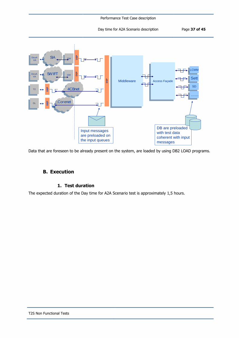
Performance Test Case description
Day time for A2A Scenario description Page 37 of 45
T2S Non Functional Tests
DB are preloaded
with test data
coherent with input
messages
DE
P
Middleware Middleware
GWGW D
EP
SIASIA
DE
PCorenetCorenet
GWGW D
EP
SWIFTSWIFT
Access FaçadeAccess Façade
LCMMLCMM
SettSett
DicoA
VA
DicoA
VA
DicoA
VA
DicoA
VA
DLDL
DE
P
4CBnet4CBnetT2
T2SDSD
…………
Input messages
are preloaded on
the input queues
Data that are foreseen to be already present on the system, are loaded by using DB2 LOAD programs.
B. Execution
1. Test duration
The expected duration of the Day time for A2A Scenario test is approximately 1,5 hours.

Performance Test Case description
Day time for U2A Scenario description Page 38 of 45
T2S Non Functional Tests
Day time for U2A Scenario description
A. Test scenario preparation
1. Test data preparation
Test cases related to the day-time U2A scenario will share a common set up and a common procedure
to allow the measurement of the different expected results under the above-mentioned workload and
inbound/outbound peak hour distribution.
Assuming a plain distribution of U2A queries during the day the scenario can be configured as follows:
Step #1 Configuration of Static Data (to be performed before Test Day):
Definition of 6 Central Banks and 6 CSDs Sytem Entities and the relevant Parties;
Each CSD has 10 CSD Participants which are also Settlement/Payment bank;
For all these Parties, a set of users with the appropriate privileges is configured;
Each Settlement/Payment Bank owns 1 T2S Dedicated Cash Accounts linked to the relevant
External RTGS account of his own Central Bank.
Each CSD Participants owns 1 Securities Account.
Each CSD is Issuer of 40 Securities, half of them defined as eligible for auto-collateralisation
by all the Central Banks and the relevant price is for the business day is loaded.
Simple Cross-CSD configurations are made to allow any CSD to be defined as Investor for any
security issued by another CSD and to be defined as eligible counterpart for any other CSD for
any Security in the System.
Links between T2S Dedicated Cash Account and Securities Accounts are configured to allow
Settlement .
No Market-Specific Attribute or Restriction Type are defined with the exception of the basic
system wide Restriction Type that are necessary for settlement purposes.
To obtain the required outbound flows, a proper set up of Message Subscrition Rules for each
T2S Party is configured.
Step #2 Initialisation of Securities Positions and Cash Balances (to be performed before Test Day):
Inbound Liquidity Transfers from RTGS to each DCA are executed to initialize all T2S
Dedicated Cash Accounts;
FOP (Corporate Actions on stock) between issuer and investor to initialize Security Account
Positions.
Step #3 Performance test executions (to be performed on the Test Day):
The whole set of U2A queries are injected into the system in one hour, validated and the
appropriate response is generated and sent to the interested Party.
Performance Test Case description
Day time for U2A Scenario description Page 39 of 45
T2S Non Functional Tests
In addition to the U2A queries, a set of 3750 Static Data U2A maintenance instructions have to be
sent to the T2S platform to simulate the U2A interface workload.
The test goals are measured according to the different Test Cases.
2. Messages loading and injection
In order to perform U2A load testing a specific web load test suite will be used to record, generate
and measure U2A activities.
A typical Web load test suite is made by different components:
load recording tool
load machines
management console
U2A patterns will be described and will produce different test flows. Each test flow will be
recorded using the load recording tool. Outcome of this phase are scripts able to simulate user
activities. Using a management console all the load scripts will be combined together producing a load
mix, in this phase is possible to provide the percentage for each script with respect to the total
amount of the generated load. Load Machines will then run several parallel user sessions (accordingly
with the SLA) each one running one load script (accordingly with the distribution set in the load mix).
During the test session the management console will collect information on the status of each load
machine and on the user experience measured during the test.
B. Execution
1. Test duration
The expected duration of the Day time for U2A Scenario test is approximately 1,5 hours.
Performance Test Case description
End Of Day Scenario description Page 40 of 45
T2S Non Functional Tests
End Of Day Scenario description
A. Test scenario preparation
1. Test data preparation
The End of Day scenario can exploit the data setup used for the Day time A2A scenario with some
additional configurations for the loading of security prices and eligibility information and to simulate
the workload of report production.
An additional set of 15 NCB has to be configured with the appropriate set of privileges.
40,500 Securities have to be created into the system and defined as eligible for autocollateralisation
by each Central Bank
During the End of Day process of the Test day 850,000 messages on valuation prices bundled into
files have to be injected in the system together with 6,300 maintenance instructions on the list of
eligible collateral.
To measure the file transfer throughput in output a set of reports reproducing the actual size of the
peak day volumes according to the table in section II.f.1 has to be generated by the Report
component of the T2S system. For each Central Bank the Report Configuration has to be properly cet
in order to allow the sending of the files.
2. Messages loading and injection
To inject the message in the system during or before the test execution, an emulator is available that
reproduce and send messages in DEP protocol format. The emulator (MassiveLoad) can run in two
ways:
Running on a separate System, it can inject messages in the input queues at regular
interval
Running on the same System, it can inject messages to the queues while the consumer
processes are stopped. At the test starting time, the queues consumer processes can be
activated and the messages are loaded into the system as arrived in the same time.
The usage of the injector depends from the real scenario that need to be tested.
Data that are foreseen to be already present on the system, are loaded by using DB2 LOAD programs.
B. Execution
1. Test duration
The expected duration of the End of Day Scenario test is approximately 1,5 hours.
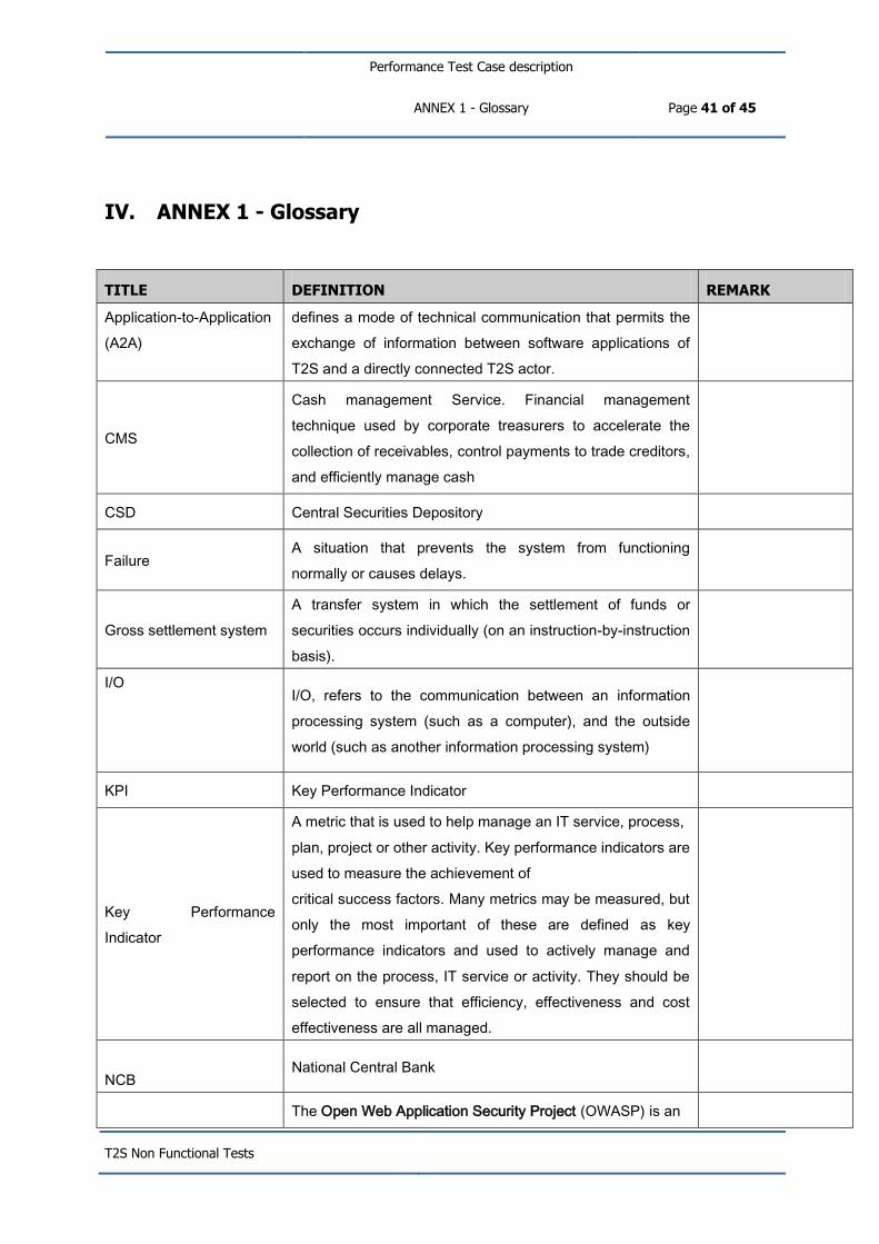
Performance Test Case description
ANNEX 1 - Glossary Page 41 of 45
T2S Non Functional Tests
IV. ANNEX 1 - Glossary
TITLE DEFINITION REMARK
Application-to-Application
(A2A)
defines a mode of technical communication that permits the
exchange of information between software applications of
T2S and a directly connected T2S actor.
CMS
Cash management Service. Financial management
technique used by corporate treasurers to accelerate the
collection of receivables, control payments to trade creditors,
and efficiently manage cash
CSD Central Securities Depository
Failure A situation that prevents the system from functioning
normally or causes delays.
Gross settlement system
A transfer system in which the settlement of funds or
securities occurs individually (on an instruction-by-instruction
basis).
I/O
I/O, refers to the communication between an information
processing system (such as a computer), and the outside
world (such as another information processing system)
KPI Key Performance Indicator
Key Performance
Indicator
A metric that is used to help manage an IT service, process,
plan, project or other activity. Key performance indicators are
used to measure the achievement of
critical success factors. Many metrics may be measured, but
only the most important of these are defined as key
performance indicators and used to actively manage and
report on the process, IT service or activity. They should be
selected to ensure that efficiency, effectiveness and cost
effectiveness are all managed.
NCB National Central Bank
The Open Web Application Security Project (OWASP) is an

Performance Test Case description
ANNEX 1 - Glossary Page 42 of 45
T2S Non Functional Tests
OWASP open-source application security project aimed at providing
standard and tools for performing application-level security
verifications.
Penetration Test
A penetration test is a method of evaluating the security of a
computer system or network by simulating an attack from
malicious outsiders and malicious insiders. The process
involves an active analysis of the system for any potential
vulnerabilities and can involve active exploitation of security
vulnerabilities.
Performance
A measure of what is achieved or delivered by a system,
process or IT service.
Query
Refers to real-time function to fulfil ad hoc information
demands. Queries can be sent to T2S continuously
throughout the day, and will be answered in real-time.
Queries are generally performed in a pull mode and are
limited to the defined data and availability of related system
resources.
RPO Recovery Point objectives
RTGS
Real-time Gross Settlement The continuous (real-time)
settlement of funds or securities transfers individually on an
order-by-order basis with intraday finality (without netting).
RTO Recovery Time objectives
SAN Storage Area Network
SLA
Service Level Agreement
Service Level Agreement
An agreement between an IT service provider and a
customer. The SLA describes the IT service, documents
service level targets, and specifies the responsibilities of the
IT service provider and the customer. A single SLA may
cover multiple IT services or multiple customers.

Performance Test Case description
ANNEX 1 - Glossary Page 43 of 45
T2S Non Functional Tests
Settlement Instruction
A settlement instruction is an order, originating from both
trading and non-trading operations, to deliver or receive
securities (or rights in securities) with or without paying an
amount of money to an ultimate beneficiary on behalf of an
originator. In case of a sale, the buyer of the securities will
need to provide the receive instruction while the seller will
need to provide the delivery instruction for the same trade.
Settlement Transaction
A common term for the two settlement instructions
necessary for any settlement activity – one instruction to
debit a securities and/or cash account and one instruction to
credit a securities and/or cash account.
SSP
Single Shared platform TARGET2 is based on a single
technical platform, known as the Single Shared Platform,
which includes payment and accounting processing services
and customer-related services.
T2
TARGET2. The second-generation TARGET system. It
settles payments in euro in central bank money and
functions on the basis of a single shared IT platform, to
which all payment orders are submitted for processing.
T2S
TARGET 2 Securities. The Eurosystem’s single technical
platform enabling central Securities depositories and NCBs
to provide core, borderless and neutral Securities settlement
services in central bank money in Europe.
TARGET Trans-European Automated Real-time Gross settlement

Performance Test Case description
ANNEX 1 - Glossary Page 44 of 45
T2S Non Functional Tests
Express Transfer system. The Eurosystem’s real-time gross
settlement system for the euro. The first-generation
TARGET system was replaced by TARGET2 in May 2008.
Throughput
The average rate of successful message delivery over a
communication channel
UDFS User Detailed Functional Specifications
URD User Requirements Document
Usable capacity
The total amount of bytes available to be written after a
system or device has been formatted for use, Usable
Capacity, is less than or equal to raw capacity. It does not
include areas set aside for system use, spares, RAID parity
areas, checksum space, host- or filesystem-level remapping,
"right sizing" of disks, disk labeling and so on.
User-to-Application
(U2A)
Defines a mode of technical communication that permits the
exchange of information between software applications of
T2S and a T2S system user through a graphical user
interface (GUI).
Vulnerability Assessment
A vulnerability assessment is the process of identifying,
quantifying, and prioritizing the vulnerabilities in a system in
order to categorize threats and drive the risk management
process.
Workload
The resources required to deliver an identifiable part of an IT
service. Workloads may be categorized by users, groups of
users, or functions within the IT service. This

Performance Test Case description
ANNEX 1 - Glossary Page 45 of 45
T2S Non Functional Tests
is used to assist in analysing and managing the capacity,
performance and utilization of configuration items and IT
services. The term is sometimes used as a synonym for
throughput.

T2S Non Functional Tests
Security Tests
Author 4CB
Version 1.8
Date 27/05/2013
Status Final draft
Classification PUBLIC

Security Tests
Page 2 of 8
T2S Non Functional Tests
1. OVERVIEW 3
1.1. METHODOLOGY USED........................................................................................................ 3
1.2. NON FUNCTIONAL REQUIREMENTS TO BE FULFILLED THROUGH TESTING ..................................... 4
1.3. LIST OF NON FUNCTIONAL SECURITY TESTS FORESEEN ........................................................... 5
1.4. HIGH LEVEL PLANNING ..................................................................................................... 5
1.5. REPORTING .................................................................................................................... 5
2. SEC_01: APPLICATION LEVEL VULNERABILITY TESTS 6
2.1. TEST OBJECTIVE .............................................................................................................. 6
2.2. TEST CASE DESCRIPTION ................................................................................................... 6
2.3. EXECUTION ..................................................................................................................... 6
3. SEC_02: T2S INFRASTRUCTURE VULNERABILITY TESTS 7
3.1. TEST OBJECTIVE .............................................................................................................. 7
3.2. TEST CASE DESCRIPTION ................................................................................................... 7
3.3. EXECUTION ..................................................................................................................... 7

Security Tests
Page 3 of 8
T2S Non Functional Tests
1. Overview
1.1. Methodology used
The T2S Security Requirements and Controls1 (T2SSRC) are derived from the high level security
requirements expressed in Chapter 18 of the T2S URD and based directly on ISO standard 27002.
The T2S SRC states that:
“As a general rule, the implementation of the security controls specified in this document is
mandatory. However, it might be that due to specified technical and/or environmental
circumstances (e.g. contradicting national legislation) the application of a particular security control is not feasible. If this was the case, it will have to be justified in the context of the
security assessment, more specifically when the compliance of T2S with the T2SSRC is
checked, why it is not possible to implement this particular security control. The associated residual risk must then be accepted.”
“All security requirements and controls included in this document are specified from a
business perspective and have to be implemented by the service provider (4CB) responsible for designing, building and operating T2S.”
The compliance and risk assessment process2 is used to assess the overall T2S Information Security
risk situation. This includes as a first step to take the defined security requirements and controls as
the reference and perform a compliance check by validating the completeness and effectiveness of
the actual implementation of these controls within the scope of T2S.
In order to assess whether the 4CB have implemented the T2S Information Security management
framework, in particular by designing, developing and operating the T2S Platform in accordance with
the T2SSRC, the following approach is adopted:
A global compliance and risk assessment process is followed, resulting in the preparation of
the T2S Pre-Production Security Assessment (PPSA), with 3 inter-related deliverables, namely:
o Answers to the Security Compliance Check Questionnaire (SCCQ) covering all questions related to the T2S SRC controls;
o The Risk Evaluation Table (RET). It provides the likelihood for each threat (of the T2S
Threat Catalogue) for which not all the relevant controls are implemented and effective, as well as the impact of the threat, taking into account the non-compliant controls;
o The Risk Treatment Plan (RTP). This plan proposes a treatment (i.e. a mitigation measure or acceptance) for all the risks listed in the RET.
This process applied to the whole T2S scope is triggered every three years, firstly before the
go-live of T2S (the “Pre-Production Security Assessment”). The PPSA will be delivered by the 4CB to the Level 2 as set out in the related validation form3 by end 2014. In turn, as
described in the Framework Agreement4, the Eurosystem will share information with the contracting CSD about the risk situation (in the form of the T2S Information Security Risk
1 See Framework Agreement Schedule 10 – Annex 2.
2 See Framework Agreement Schedule 10 – Section 4: The T2S Information Security Risk Management Process.
3 See the PPSA Validation Form in the L2-L3 Agreement – Annex III.
4 See Framework Agreement Schedule 10 – Section 4.2: Deliverables to the Contracting CSD.

Security Tests
Page 4 of 8
T2S Non Functional Tests
Evaluation Table or ISRET and, together with each ISRET entry, the proposed corresponding
T2S Information Security Risk Treatment Plan or ISRTP).
In addition, for one particular security control (T2SSRC 14.2.2 “Technical Compliance
Checking”), specific non-functional tests will be executed. The purpose of this document is to
describe how these specific non-functional test cases will be defined and executed. As a
result, the 4CB will deliver prior to the go-live of T2S a risk assessment of the residual
vulnerabilities (if any) considering mitigation measures implemented before T2S starts its
operations. As a complement to the ISRET and ISRTP generated on the basis of the PPSA, the
Level 2 will share the relevant information with the contracting CSD about the risk situation
entailed by any residual vulnerability that may still be present at the go-live date.
1.2. Non Functional requirements to be fulfilled through testing
Specific test cases will address URD T2S.18.1300 / T2SSRC 14.2.2 “Technical Compliance Checking”.
These tests will aim at establishing the level of compliance obtained by the T2S Platform with
technical security specifications. As any non-compliance will be identified as a potential cause for risks
materialising, the finality of these tests will be to assess to what extent (even partially) non-compliant
implementation of security controls may lead to any residual risks.
Vulnerability assessment and penetration test5 activities will be conducted, resulting in the production
of a finding reports which will be used to define action plans aiming at mitigating the vulnerabilities.
5 Penetration tests will be conducted on a subset of targets selected taking into account the architectural design and the results obtained in a
first step during the vulnerability tests.

Security Tests
Page 5 of 8
T2S Non Functional Tests
1.3. List of Non Functional Security Tests foreseen
The following table summarizes the test cases envisaged. For each test case the following information
are reported:
ID Short description
SEC_01 Application level vulnerability tests
SEC_02 Infrastructure vulnerability tests
As their contents may be used to harm the interests of the System Owner, neither the detailed
documents describing test cases nor the detailed reports of findings will be published. In compliance
with T2S SRC 14.2.2 and security best practices, only a restricted list of authorised 4CB security
experts and managers will have access to these sensitive documents.
It must be noted that (again, in line with T2S SRC 14.2.26) vulnerability tests and penetration tests
may be executed by third party security experts duly mandated to do so under the proper supervision
of competent and authorised 4CB staff members.
As explained in section 1.2, the deliverables shared with the Level 2 will be limited to risk
assessments of the residual vulnerabilities. These assessments will reflect the risk situation
after the implementation of actions addressing the findings identified during the aforementioned
tests.
1.4. High level planning
The risk assessments entailed by SEC_01 and SEC_02 will be included in the final NFT report (to be
delivered on 01/12/2014). No intermediate situation will be delivered in the August 2014
draft report. The content of the final report will not include the results of security tests;
however it will provide general information about the execution of the tests.
1.5. Reporting
Taking into account the findings documented in the test reports, the mitigating action plans and the
actual implementation status of the actions at a reference point in time, the Eurosystem security
experts will deliver to the contracting CSD and Central Banks as per the T2S Information Security Risk
Management process7 the Risk Evaluation Table and the risk Treatment Plan with an indication of the
residual risk situation after the implementation of the actions addressing all the findings identified
during the tests. Each identified risk will be scored in terms of likelihood and impact using the grading
scales applicable in the T2S context.
6 Technical compliance checking (e.g. penetration tests and/or vulnerability assessments) must be performed either manually
(supported by appropriate software tools, if necessary) by an experienced system engineer, and/or with the assistance of automated tools, which generate a technical report for subsequent interpretation by technical specialists.
7 Chapter 4.2 of the schedule 10 of the Framework Agreement,

Security Tests
Page 6 of 8
T2S Non Functional Tests
2. SEC_01: Application level vulnerability tests
2.1. Test objective
The objective of the application level vulnerability tests is to address URD T2S.18.1300 / T2S
SRC 14.2.2 (“Technical Compliance Checking”) by ensuring that the T2S applications are free of any
relevant security threats and able to manage user interaction while avoiding the Open Web
Application Security Project (OWASP) security top ten8 vulnerabilities.
2.2. Test case description
The test activity will be conducted executing the applications and checking the presence of
vulnerabilities according to the OWASP testing criteria9.
The components involved in the activity will be all web based software modules of the applications
connected to external networks.
The tests on the software modules will be conducted in a “Black Box” approach trying to identifying
the typical web vulnerabilities10
The application level vulnerability tests will follow the guidelines provided in the OWASP Testing
Guide. Thus tests will be performed in the framework of the following categorisation: Information
Gathering, Configuration Management Testing, Authentication Testing, Session Management Testing,
Authorization Testing, Business Logic Testing, Data Validation Testing, Denial of Service Testing, Web
Services Testing, AJAX Testing.
2.3. Execution
The criteria used for the application level vulnerability test phase will be defined in accordance with
the OWASP testing methodology.
The output of the activity will be a 4CB internal report listing all of the identified non compliances and
potential security issues.
8 https://www.owasp.org/index.php/Category:OWASP_Top_Ten_Project
9 https://www.owasp.org/index.php/Category:OWASP_Testing_Project
10 The web vulnerabilities can be exploited, for example, with the following attacks: Injection, Cross-Site Scripting (XSS), Broken Authentication and Session Management, Insecure Direct Object References, Cross-Site Request Forgery (CSRF), Security Misconfiguration, Insecure Cryptographic Storage, Failure to Restrict URL Access, Insufficient Transport Layer Protection, Unvalidated Redirects and Forwards, etc.

Security Tests
Page 7 of 8
T2S Non Functional Tests
3. SEC_02: T2S infrastructure vulnerability tests
3.1. Test objective
The objective of the infrastructure vulnerability tests is to address URD T2S.18.1300 / T2S SRC
14.2.2 (“Technical Compliance Checking”) by ensuring that infrastructure built to host and operate the
T2S platform is free of any relevant security threat and is not exposing any unneeded service.
3.2. Test case description
The internal T2S components, not connected to external networks, will be submitted to a
vulnerability assessment. The test will be executed for each category of components, not repeating it
for components of identical configuration.
The T2S components connected to external networks will be submitted to a vulnerability
assessment. Additionally, a few selected critical components will be submitted to penetration test
activities. The tests will be executed for each category of components.
The involved components are the T2S assets accessible using IP addresses11:
all installed operating systems12 and the related base components, and
all active network devices.
As some components are shared by T2S and the TARGET2 SSP, the test activity will also be conducted
referring, for those components used by T2S, to the outcome of similar infrastructure vulnerability
tests performed by TARGET2.
3.3. Execution
The test activities will be performed using automatic security software tools where possible, or
alternatively by performing manually a compliance checking of the configurations of the assets
according the applicable “T2S SRC” controls13.
All the relevant T2S SRC controls must be implemented for all the components included in the test.
The components must also be configured according to the security best practices.
11 Non-IT devices will not be included in the tests. For appliances, tests will conducted where technically possible (e.g. the appliances must have
an IP address and must have some software interacting wirh the network).
12 The z/OS systems’ configuration will be verified manually, based on configuration documentation.
13 The activity will be conducted manually checking if the configuration of the components is in line with the applicable T2S SRC controls.

Security Tests
Page 8 of 8
T2S Non Functional Tests
The output of the activity will be a 4CB internal report listing all of the identified non compliances and
potential security issues.