T2 / T3 - Standen
64
T2 / T3 Potato Harvester Control System (machines from 2014) Standen Engineering Limited. Hereward Works, Station Road, Ely, Cambridgeshire. CB7 4BP England. Tel: +44 (0)1353 661111 www.standen.co.uk Fax: +44 (0)1353 662370
Transcript of T2 / T3 - Standen

T2 / T3 Potato Harvester Control System (machines from 2014)
Standen Engineering Limited. Hereward Works, Station Road, Ely, Cambridgeshire.
CB7 4BP England.
Tel: +44 (0)1353 661111 www.standen.co.uk Fax: +44 (0)1353 662370


The contents of this handbook, although correct at the time of publication, may be subject to alteration by the manufacturers without prior notice. Standen Engineering Limited operate a policy of continual product development. Therefore, some illustrations and/or text within this publication may differ from your machine. The copyright of this handbook is the property of Standen Engineering Limited, Hereward Works, Station Road, Ely, Cambridgeshire CB7 4BP England. This handbook is issued on the condition that it must not be used, copied or exhibited without their written permission.
IMPORTANT
This operator’s handbook should be regarded as part of the machine. Suppliers of both new and second-hand machines are advised to retain documentary evidence that this
handbook was supplied along with the machine.

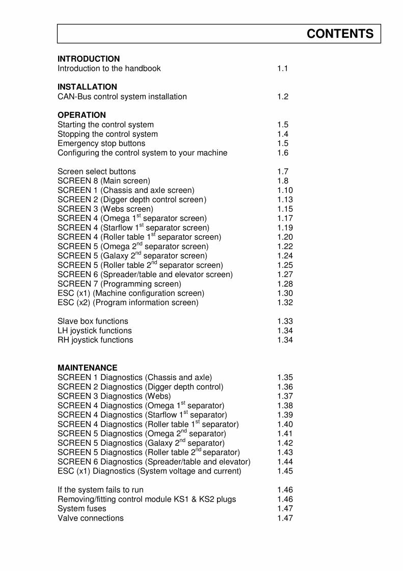
INTRODUCTION Introduction to the handbook 1.1 INSTALLATION CAN-Bus control system installation 1.2 OPERATION Starting the control system 1.5 Stopping the control system 1.4 Emergency stop buttons 1.5 Configuring the control system to your machine 1.6 Screen select buttons 1.7 SCREEN 8 (Main screen) 1.8 SCREEN 1 (Chassis and axle screen) 1.10 SCREEN 2 (Digger depth control screen ) 1.13 SCREEN 3 (Webs screen) 1.15 SCREEN 4 (Omega 1st separator screen) 1.17 SCREEN 4 (Starflow 1st separator screen) 1.19 SCREEN 4 (Roller table 1st separator screen) 1.20 SCREEN 5 (Omega 2nd separator screen) 1.22 SCREEN 5 (Galaxy 2nd separator screen) 1.24 SCREEN 5 (Roller table 2nd separator screen) 1.25 SCREEN 6 (Spreader/table and elevator screen) 1.27 SCREEN 7 (Programming screen) 1.28 ESC (x1) (Machine configuration screen) 1.30 ESC (x2) (Program information screen) 1.32 Slave box functions 1.33 LH joystick functions 1.34 RH joystick functions 1.34 MAINTENANCE SCREEN 1 Diagnostics (Chassis and axle) 1.35 SCREEN 2 Diagnostics (Digger depth control) 1.36 SCREEN 3 Diagnostics (Webs) 1.37 SCREEN 4 Diagnostics (Omega 1st separator) 1.38 SCREEN 4 Diagnostics (Starflow 1st separator) 1.39 SCREEN 4 Diagnostics (Roller table 1st separator) 1.40 SCREEN 5 Diagnostics (Omega 2nd separator) 1.41 SCREEN 5 Diagnostics (Galaxy 2nd separator) 1.42 SCREEN 5 Diagnostics (Roller table 2nd separator) 1.43 SCREEN 6 Diagnostics (Spreader/table and elevator) 1.44 ESC (x1) Diagnostics (System voltage and current) 1.45 If the system fails to run 1.46 Removing/fitting control module KS1 & KS2 plugs 1.46 System fuses 1.47 Valve connections 1.47
CONTENTS
Introduction to the Handbook This handbook provides the information for the operation, adjustment and maintenance of your Standen T2 / T3 CAN-Bus electrical control system. To enable you to achieve the best results from the machine, the manufacturer recommends that you read the handbook thoroughly prior to using the machine for the first time.
Throughout this handbook the terms 'front', 'rear', 'left-hand' (LH) and 'right-hand' (RH) are derived from the tractor driver’s position facing forward in the normal direction of travel. Adjustments to the machine may have to be made singly or in combination according soil conditions. Always allow the machine to settle to a new setting before making further adjustments.
TRANSPORT WARNING:
WELDING WARNING:
1.1 INTRODUCTION
This symbol indicates important safety messages within this handbook. When you see this symbol, be alert to the possibility of injury to yourself or others and/or damage to the machine and carefully read the message that follows.
Before carrying out any welding on the harvester always disconnect the KS1 & KS2 plugs from the bottom of the harvester control module and completely disconnect the harvester from the tractor. Failure to observe the above precautions may cause severe damage to the harvester and tractor electrical systems. For plug removal procedure
see the maintenance section of this handbook.
Always switch off the control system before transporting the
harvester on the road.

CAN-Bus Control System Installation The harvester CAN-Bus control system requires a 12 Volt negative earth power supply fed directly from the tractor battery using the 50Amp power lead supplied. Red cable to positive (+) and black cable to negative (-).
Ensure the polarity of the battery connections are made correctly to prevent damage to the system components.
The touch-screen terminal (fig 1) and the slave box (fig 2) should be mounted inside the tractor cab so that controls can be comfortably reached from the drivers seat.
Care should be taken to ensure the units do not obstruct the driver’s visibility and access to the tractor controls. Always use existing mounting holes within the cab, as drilling additional holes may reduce the cab’s integrity and is illegal.
The cab loom (fig 3) should be routed into the cab through existing apertures to allow the 12 pin plug to couple into the front of the slave box. Mount the loom plug housing to the rear of the tractor cab so that it can be reached from the ground and through the opened rear window. Connect the display loom (fig 4) into the plug on the rear of the touch-screen terminal, and route it safely to plug into the 4 pin plug on the front of the slave box. Connect the power lead (fig 5) to the cab loom plug. The tractor loom plug housing is used as the main power lead junction and the power pins are permanently live when connected to the battery. When all mechanical and hydraulic connections have been made to the tractor, the harvester loom can be plugged into the cab loom completing the electrical circuit. Ensure the plug is clean and dry and has not been dropped on the ground. The plug latch must be fully closed to ensure correct connection. When not in use, the harvester plug should be latched into the blank cover on the support stem. The circuit is completed by the manual emergency stop switch(es) at the rear of the harvester which allow the main power relays to latch on.
INSTALLATION 1.2
Fig 1 Fig 2
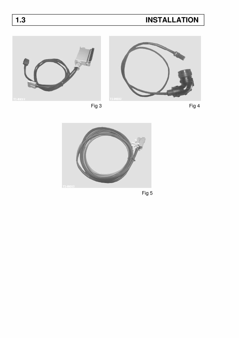
Fig 3 Fig 4
Fig 5
1.3 INSTALLATION
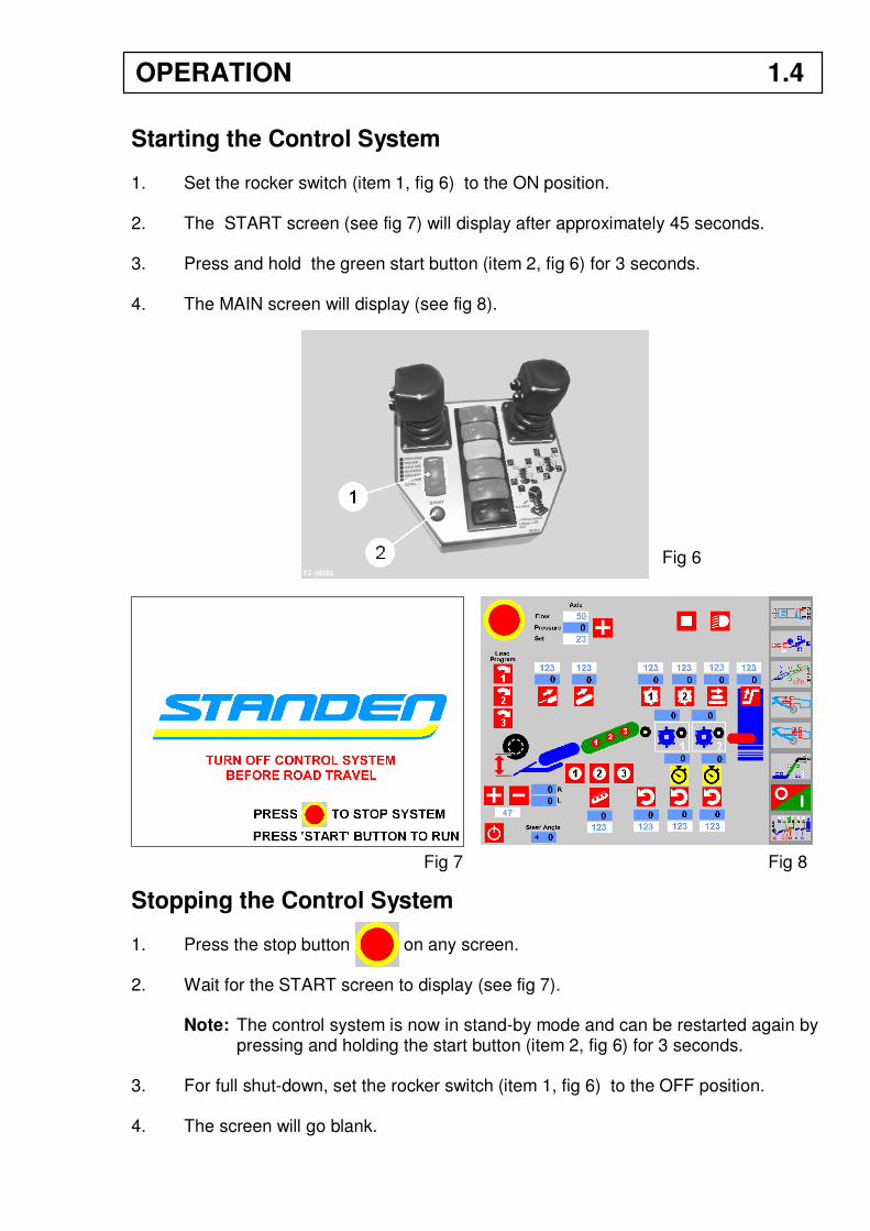
Starting the Control System 1. Set the rocker switch (item 1, fig 6) to the ON position. 2. The START screen (see fig 7) will display after approximately 45 seconds. 3. Press and hold the green start button (item 2, fig 6) for 3 seconds. 4. The MAIN screen will display (see fig 8).
Stopping the Control System 1. Press the stop button on any screen. 2. Wait for the START screen to display (see fig 7).
Note: The control system is now in stand-by mode and can be restarted again by pressing and holding the start button (item 2, fig 6) for 3 seconds.
3. For full shut-down, set the rocker switch (item 1, fig 6) to the OFF position. 4. The screen will go blank.
Fig 6
Fig 7
OPERATION 1.4
Fig 8
Emergency Stop Buttons
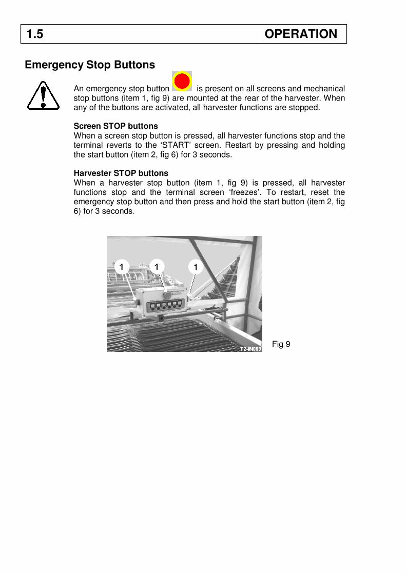
An emergency stop button is present on all screens and mechanical stop buttons (item 1, fig 9) are mounted at the rear of the harvester. When any of the buttons are activated, all harvester functions are stopped. Screen STOP buttons When a screen stop button is pressed, all harvester functions stop and the terminal reverts to the ‘START’ screen. Restart by pressing and holding the start button (item 2, fig 6) for 3 seconds. Harvester STOP buttons When a harvester stop button (item 1, fig 9) is pressed, all harvester functions stop and the terminal screen ‘freezes’. To restart, reset the emergency stop button and then press and hold the start button (item 2, fig 6) for 3 seconds.
Fig 9
1.5 OPERATION
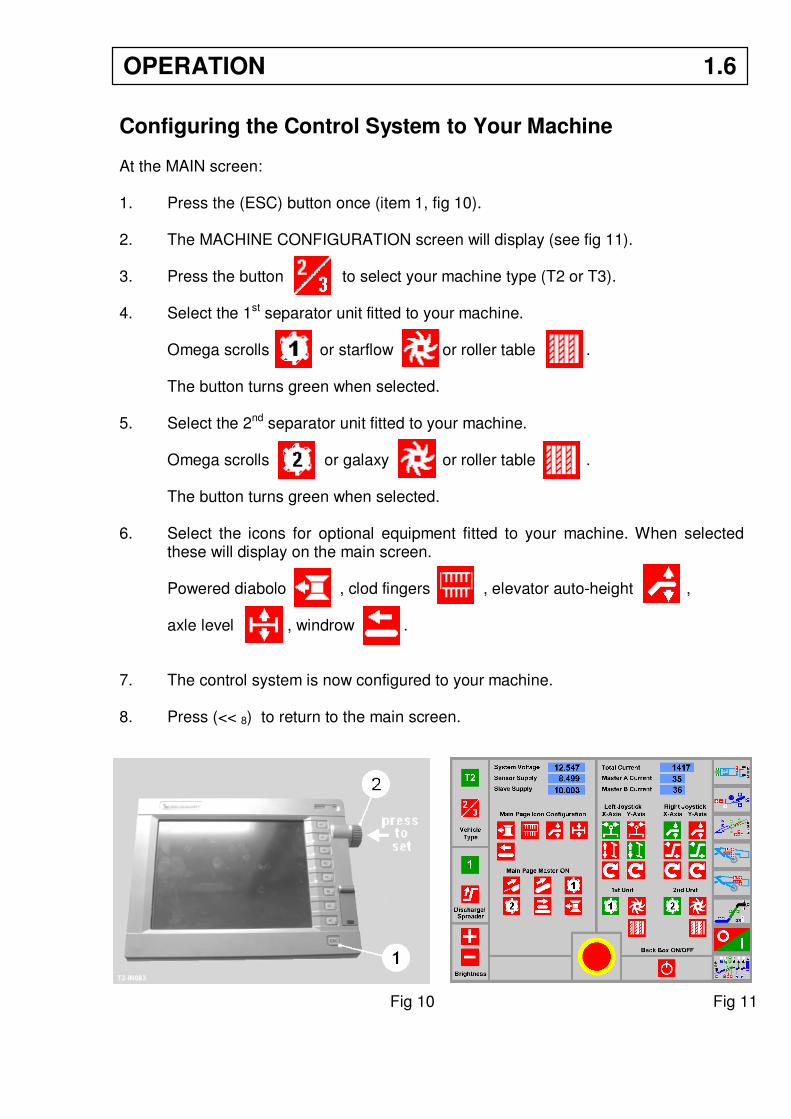
Configuring the Control System to Your Machine At the MAIN screen: 1. Press the (ESC) button once (item 1, fig 10). 2. The MACHINE CONFIGURATION screen will display (see fig 11). 3. Press the button to select your machine type (T2 or T3). 4. Select the 1st separator unit fitted to your machine.
Omega scrolls or starflow or roller table . The button turns green when selected.
5. Select the 2nd separator unit fitted to your machine. Omega scrolls or galaxy or roller table .
The button turns green when selected. 6. Select the icons for optional equipment fitted to your machine. When selected
these will display on the main screen. Powered diabolo , clod fingers , elevator auto-height ,
axle level , windrow . 7. The control system is now configured to your machine. 8. Press (<< 8) to return to the main screen.
Fig 10 Fig 11
OPERATION 1.6
Screen Select Buttons On the RH side of the terminal screen is a row of buttons which link to individual screens containing the full range of functions available complete with parameter and diagnostic information.
SCREEN 1 (Chassis and Axle Screen) This screen covers drawbar, axle side shift, axle steering and machine levelling.
SCREEN 2 (Digger Depth Screen) This screen covers automatic depth control, manual depth control and single side lifting.
SCREEN 3 (Webs Screen) This screen covers web functions, agitation, VariSep height, haulm roller speed and rotation.
SCREEN 4 (1st Separator Screen) Depending on separator configuration, the 1st separator speeds and heights are covered from this screen. SCREEN 5 (2nd Separator Screen) Depending on the separator configuration, the 2nd separator speeds and heights are covered from this screen.
SCREEN 6 (Spreader / Table and Elevator Screen) This screen covers the spreader / picking table and discharge elevator speeds, height, and auto-height functions. SCREEN 7 (Programming Screen) This screen covers save/load speed program, start/stop sequence programming, restore default settings. SCREEN 8 (Main screen) This screen covers the commonly used functions and speed adjustments.
ESC (x1) (Machine Configuration screen) This screen covers machine type (T2 or T3), 1st & 2nd separator type, joystick configuration, additional main page icons, simultaneous start elements, back box ON/OFF, system voltage & current, oil temperature etc.. ESC (x2) (Program information screen) Program version and date.
1.7 OPERATION
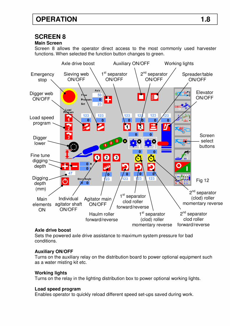
SCREEN 8 Main Screen Screen 8 allows the operator direct access to the most commonly used harvester functions. When selected the function button changes to green. Axle drive boost Sets the powered axle drive assistance to maximum system pressure for bad conditions. Auxiliary ON/OFF Turns on the auxiliary relay on the distribution board to power optional equipment such as a water misting kit etc. Working lights Turns on the relay in the lighting distribution box to power optional working lights. Load speed program Enables operator to quickly reload different speed set-ups saved during work.
Emergency stop
Axle drive boost Auxiliary ON/OFF Working lights
Digger web ON/OFF
Sieving web ON/OFF
Load speed program
Fine tune digging depth
Main elements
ON
Individual agitator shaft
ON/OFF
Agitator main ON/OFF
1st separator ON/OFF
2nd separator ON/OFF
Spreader/table ON/OFF
Elevator ON/OFF
Haulm roller forward/reverse
1st separator clod roller
forward/reverse
2nd separator clod roller
forward/reverse
Screen select
buttons
Digger lower
Fig 12 Digging depth (mm)
OPERATION 1.8
1st separator (clod) roller
momentary reverse
2nd separator (clod) roller
momentary reverse
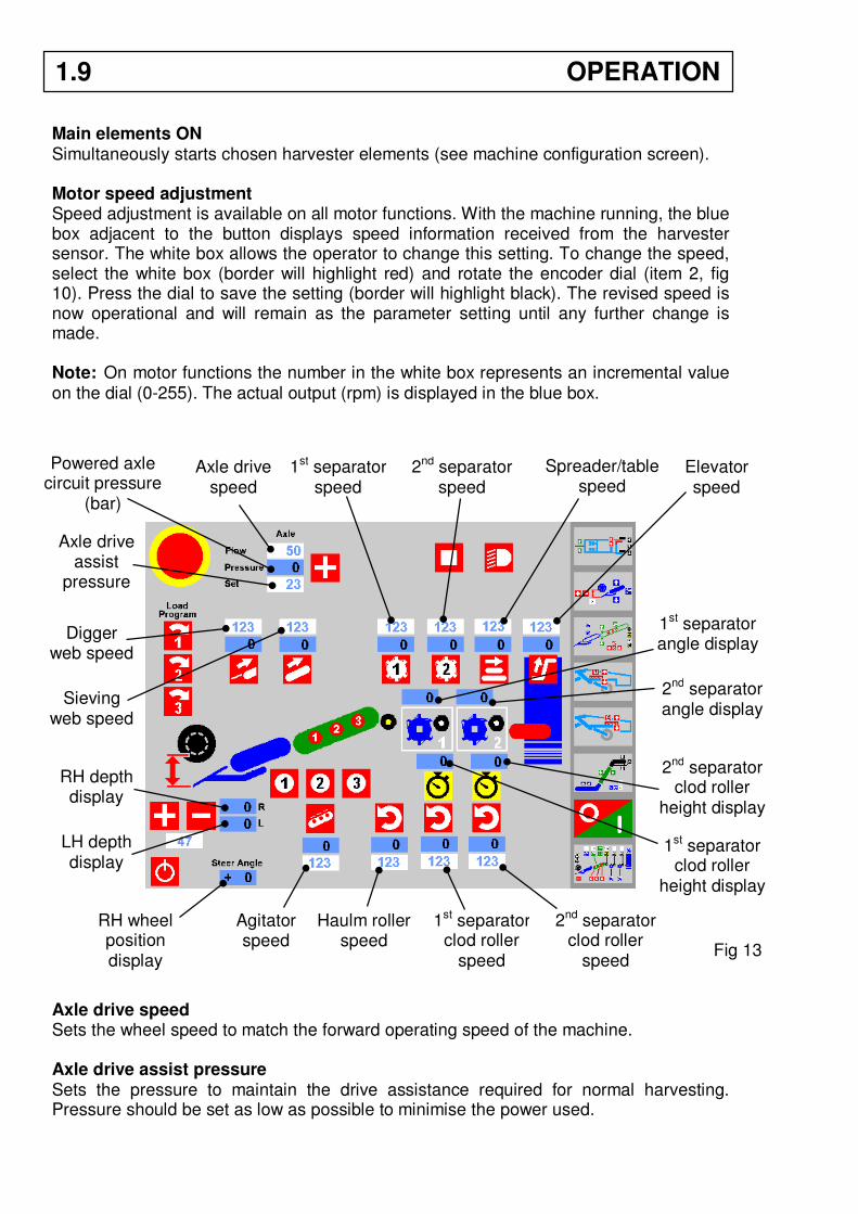
Main elements ON Simultaneously starts chosen harvester elements (see machine configuration screen). Motor speed adjustment Speed adjustment is available on all motor functions. With the machine running, the blue box adjacent to the button displays speed information received from the harvester sensor. The white box allows the operator to change this setting. To change the speed, select the white box (border will highlight red) and rotate the encoder dial (item 2, fig 10). Press the dial to save the setting (border will highlight black). The revised speed is now operational and will remain as the parameter setting until any further change is made. Note: On motor functions the number in the white box represents an incremental value on the dial (0-255). The actual output (rpm) is displayed in the blue box. Axle drive speed Sets the wheel speed to match the forward operating speed of the machine. Axle drive assist pressure Sets the pressure to maintain the drive assistance required for normal harvesting. Pressure should be set as low as possible to minimise the power used.
Axle drive speed
Powered axle circuit pressure
(bar)
Axle drive assist
pressure
Digger web speed
Sieving web speed
1st separator speed
2nd separator speed
Spreader/table speed
Elevator speed
RH depth display
LH depth display
RH wheel position display
Agitator speed
Haulm roller speed
1st separator clod roller
speed
2nd separator clod roller
speed Fig 13
1st separator angle display
2nd separator angle display
2nd separator clod roller
height display
1st separator clod roller
height display
1.9 OPERATION
SCREEN 1
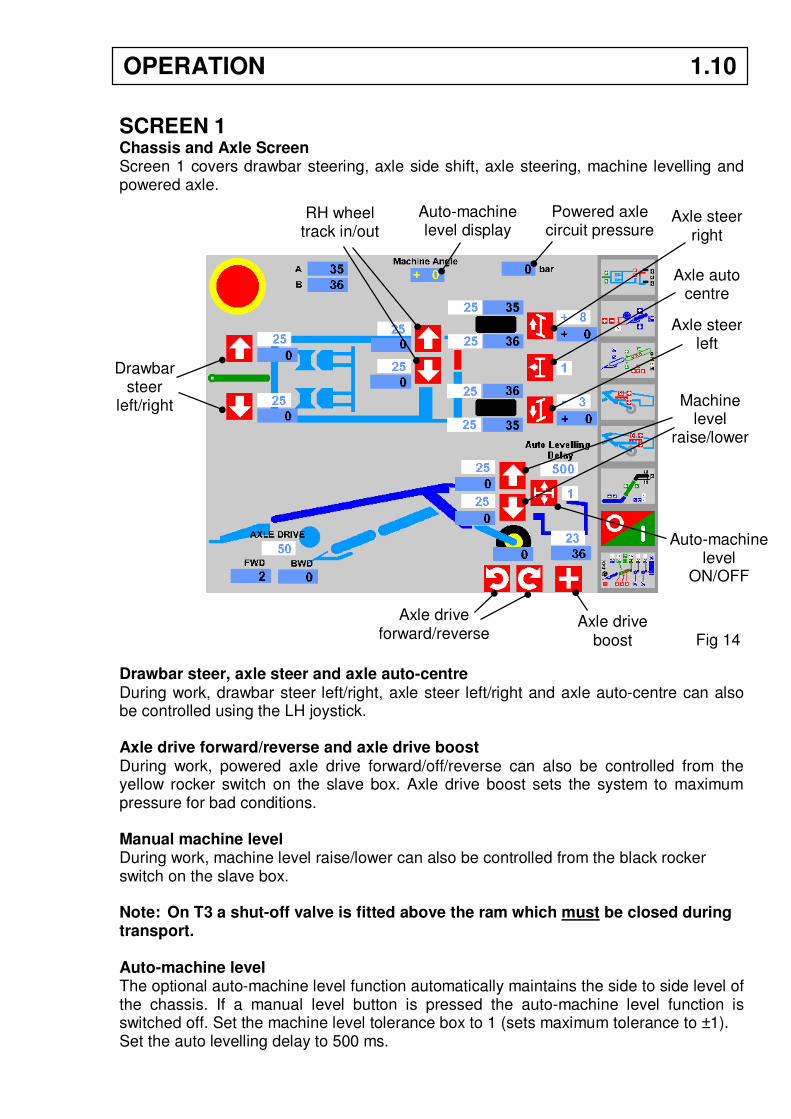
Chassis and Axle Screen Screen 1 covers drawbar steering, axle side shift, axle steering, machine levelling and powered axle. Drawbar steer, axle steer and axle auto-centre During work, drawbar steer left/right, axle steer left/right and axle auto-centre can also be controlled using the LH joystick. Axle drive forward/reverse and axle drive boost During work, powered axle drive forward/off/reverse can also be controlled from the yellow rocker switch on the slave box. Axle drive boost sets the system to maximum pressure for bad conditions. Manual machine level During work, machine level raise/lower can also be controlled from the black rocker switch on the slave box. Note: On T3 a shut-off valve is fitted above the ram which must be closed during transport. Auto-machine level The optional auto-machine level function automatically maintains the side to side level of the chassis. If a manual level button is pressed the auto-machine level function is switched off. Set the machine level tolerance box to 1 (sets maximum tolerance to ±1). Set the auto levelling delay to 500 ms.
Drawbar steer
left/right
RH wheel track in/out
Axle steer right
Axle steer left
Axle auto centre
Auto-machine level
ON/OFF
Machine level
raise/lower
Axle drive forward/reverse
Axle drive boost Fig 14
OPERATION 1.10
Auto-machine level display
Powered axle circuit pressure
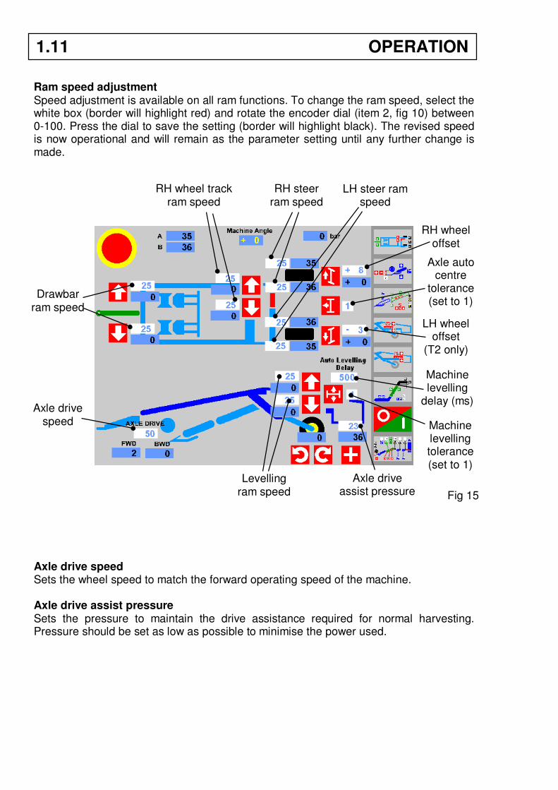
Ram speed adjustment Speed adjustment is available on all ram functions. To change the ram speed, select the white box (border will highlight red) and rotate the encoder dial (item 2, fig 10) between 0-100. Press the dial to save the setting (border will highlight black). The revised speed is now operational and will remain as the parameter setting until any further change is made.
Axle drive speed Sets the wheel speed to match the forward operating speed of the machine. Axle drive assist pressure Sets the pressure to maintain the drive assistance required for normal harvesting. Pressure should be set as low as possible to minimise the power used.
Drawbar ram speed
RH wheel track ram speed
RH steer ram speed
LH steer ram speed
Levelling ram speed
RH wheel offset
LH wheel offset
(T2 only)
Axle drive speed
Axle auto centre
tolerance (set to 1)
Machine levelling tolerance (set to 1)
Axle drive assist pressure Fig 15
1.11 OPERATION
Machine levelling
delay (ms)
Wheel Centring Parameters To set the wheel centre position: 1. Set the axle auto-centre tolerance box to 1 (sets maximum tolerance to ±1). 2. Using the axle steer right/left buttons, set the RH wheel to the straight-ahead
position. 3. Select the RH WHEEL OFFSET box. The border will highlight in red. 4. Rotate the encoder dial (item 2, fig 10) until the blue box reads + 0. This sets the
centre position on the RH steering sensor. 5. Press the encoder dial to save the revised figure. The border will change to black.
The RH wheel centre position is now set. 6. (T3) If necessary, set the LH wheel to match the RH wheel as per the instructions
in the operator’s handbook (see steering ram link circuit).
(T2) Using the axle steer right/left buttons, set the LH wheel to the straight-ahead position.
7. Select the LH WHEEL OFFSET box. 8. Rotate the encoder dial (item 2, fig 10) until the blue box reads + 0. This sets the
centre position on the LH steering sensor. 9. Press the encoder dial to save the revised figure. The LH wheel centre position is
now set. 10. Check both wheels centre correctly. If necessary, reset the steering ram speed parameters to ensure the wheels arrive at the centre position at the same time.
OPERATION 1.12
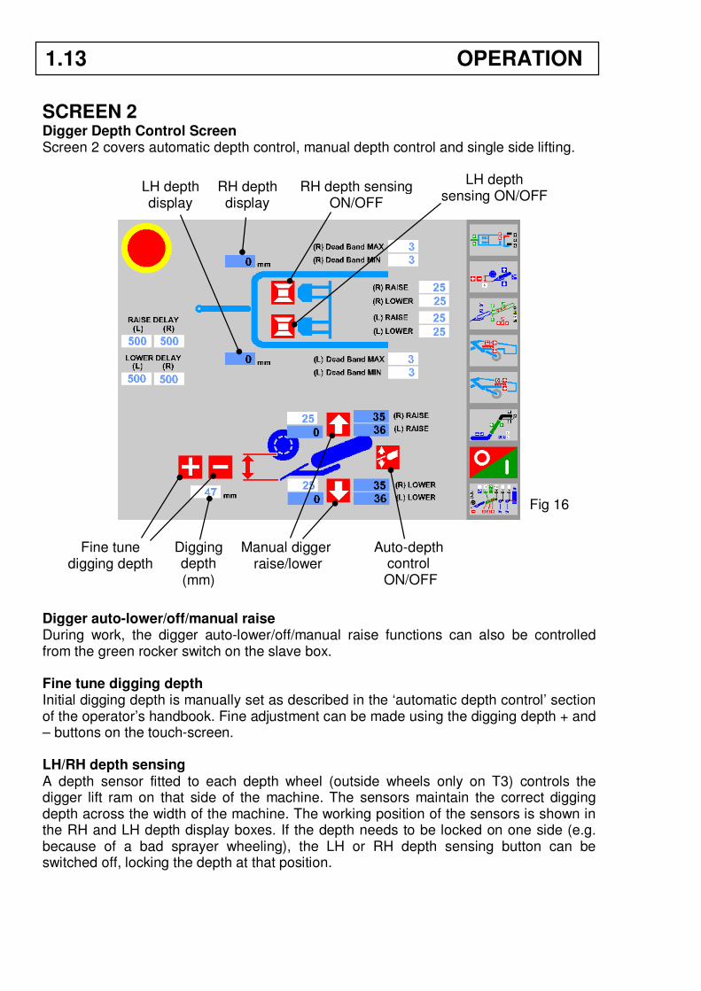
SCREEN 2
Digger Depth Control Screen Screen 2 covers automatic depth control, manual depth control and single side lifting. Digger auto-lower/off/manual raise During work, the digger auto-lower/off/manual raise functions can also be controlled from the green rocker switch on the slave box. Fine tune digging depth Initial digging depth is manually set as described in the ‘automatic depth control’ section of the operator’s handbook. Fine adjustment can be made using the digging depth + and – buttons on the touch-screen. LH/RH depth sensing A depth sensor fitted to each depth wheel (outside wheels only on T3) controls the digger lift ram on that side of the machine. The sensors maintain the correct digging depth across the width of the machine. The working position of the sensors is shown in the RH and LH depth display boxes. If the depth needs to be locked on one side (e.g. because of a bad sprayer wheeling), the LH or RH depth sensing button can be switched off, locking the depth at that position.
LH depth sensing ON/OFF
Fine tune digging depth
Manual digger raise/lower
Auto-depth control
ON/OFF
Digging depth
(mm)
Fig 16
RH depth sensing ON/OFF
LH depth display
RH depth display
1.13 OPERATION
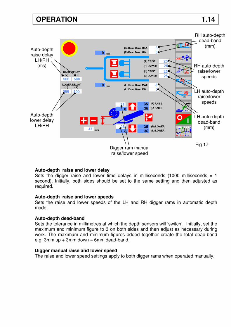
Auto-depth raise and lower delay Sets the digger raise and lower time delays in milliseconds (1000 milliseconds = 1 second). Initially, both sides should be set to the same setting and then adjusted as required. Auto-depth raise and lower speeds Sets the raise and lower speeds of the LH and RH digger rams in automatic depth mode. Auto-depth dead-band Sets the tolerance in millimetres at which the depth sensors will ‘switch’. Initially, set the maximum and minimum figure to 3 on both sides and then adjust as necessary during work. The maximum and minimum figures added together create the total dead-band e.g. 3mm up + 3mm down = 6mm dead-band. Digger manual raise and lower speed The raise and lower speed settings apply to both digger rams when operated manually.
RH auto-depth dead-band
(mm)
LH auto-depth dead-band
(mm)
Auto-depth raise delay
LH/RH (ms)
Auto-depth lower delay
LH/RH (ms)
RH auto-depth raise/lower
speeds
LH auto-depth raise/lower
speeds
Digger ram manual raise/lower speed
Fig 17
OPERATION 1.14
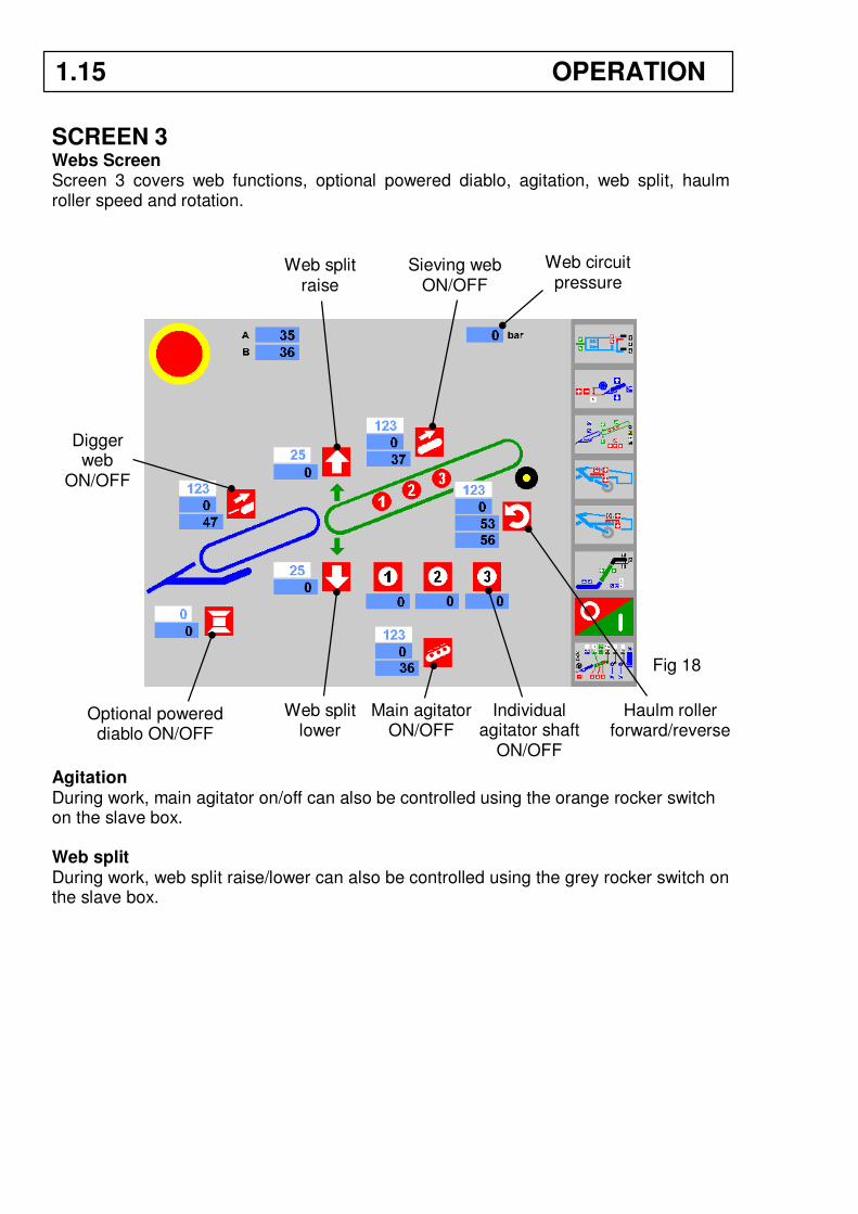
SCREEN 3
Webs Screen Screen 3 covers web functions, optional powered diablo, agitation, web split, haulm roller speed and rotation. Agitation During work, main agitator on/off can also be controlled using the orange rocker switch on the slave box. Web split During work, web split raise/lower can also be controlled using the grey rocker switch on the slave box.
Digger web
ON/OFF
Sieving web ON/OFF
Web split raise
Web split lower
Main agitator ON/OFF
Individual agitator shaft
ON/OFF
Haulm roller forward/reverse
Fig 18
1.15 OPERATION
Web circuit pressure
Optional powered diablo ON/OFF
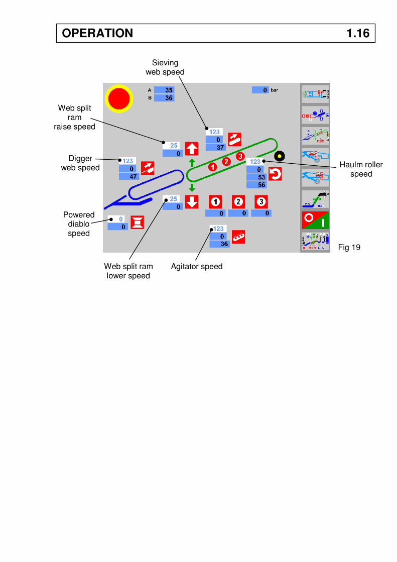
Digger web speed
Sieving web speed
Web split ram
raise speed
Web split ram lower speed
Agitator speed
Haulm roller speed
Fig 19
OPERATION 1.16
Powered diablo speed
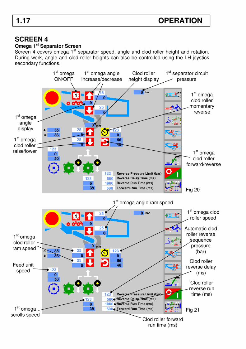
SCREEN 4 Omega 1st Separator Screen Screen 4 covers omega 1st separator speed, angle and clod roller height and rotation. During work, angle and clod roller heights can also be controlled using the LH joystick secondary functions.
1st omega ON/OFF
1st omega angle increase/decrease
1st omega clod roller raise/lower 1st omega
clod roller forward/reverse
Fig 20
Fig 21
1st omega angle ram speed
1st omega clod roller speed
1st omega clod roller ram speed
Feed unit speed
1st omega scrolls speed
1st omega angle
display
Clod roller height display
1.17 OPERATION
1st separator circuit pressure
1st omega clod roller
momentary reverse
Automatic clod roller reverse
sequence pressure
(bar)
Clod roller reverse delay
(ms)
Clod roller reverse run time (ms)
Clod roller forward run time (ms)

Automatic clod roller reverse pressure During harvesting it may be necessary to change the pressure at which the rollers reverse. The automatic reverse sequence is triggered by a pressure transducer that senses the operating pressure within the system. Increase or decrease the reverse pressure in small steps until the required operation is achieved. Roller reverse delay Sets the time delay in milliseconds before triggering the reverse sequence. (1000 milliseconds = 1 second). Roller reverse run time Sets the length of time in milliseconds that the rollers run in reverse mode when clearing a blockage. Roller forward run time Sets the length of time in milliseconds that the rollers run in forward mode before reversing again if the blockage is still present. Momentary roller reverse Starts the reverse sequence to allow stones and trash seen by the operator to be ejected before a blockage occurs.
OPERATION 1.18
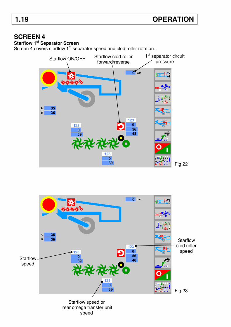
SCREEN 4 Starflow 1st Separator Screen Screen 4 covers starflow 1st separator speed and clod roller rotation.
Fig 22
Starflow ON/OFF Starflow clod roller forward/reverse
Starflow speed
Starflow clod roller
speed
Starflow speed or rear omega transfer unit
speed
Fig 23
1.19 OPERATION
1st separator circuit pressure
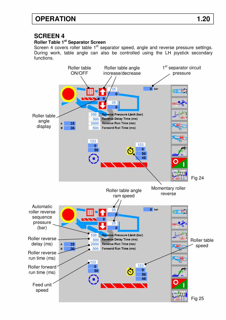
SCREEN 4 Roller Table 1st Separator Screen Screen 4 covers roller table 1st separator speed, angle and reverse pressure settings. During work, table angle can also be controlled using the LH joystick secondary functions.
Roller table ON/OFF
Roller table angle increase/decrease
Momentary roller reverse
Roller table angle
display
Fig 24
Roller table speed
Roller table angle ram speed
Feed unit speed
Automatic roller reverse
sequence pressure
(bar)
Roller reverse delay (ms)
Roller reverse run time (ms)
Roller forward run time (ms)
Fig 25
OPERATION 1.20
1st separator circuit pressure

Automatic roller table reverse pressure During harvesting it may be necessary to change the pressure at which the rollers reverse. The automatic reverse sequence is triggered by a pressure transducer that senses the operating pressure within the system. Increase or decrease the reverse pressure in small steps until the required operation is achieved. Roller reverse delay Sets the time delay in milliseconds before triggering the reverse sequence. (1000 milliseconds = 1 second). Roller reverse run time Sets the length of time in milliseconds that the rollers run in reverse mode when clearing a blockage. Roller forward run time Sets the length of time in milliseconds that the rollers run in forward mode before reversing again if the blockage is still present. Momentary roller reverse Starts the reverse sequence to allow stones and trash seen by the operator to be ejected before a blockage occurs.
1.21 OPERATION
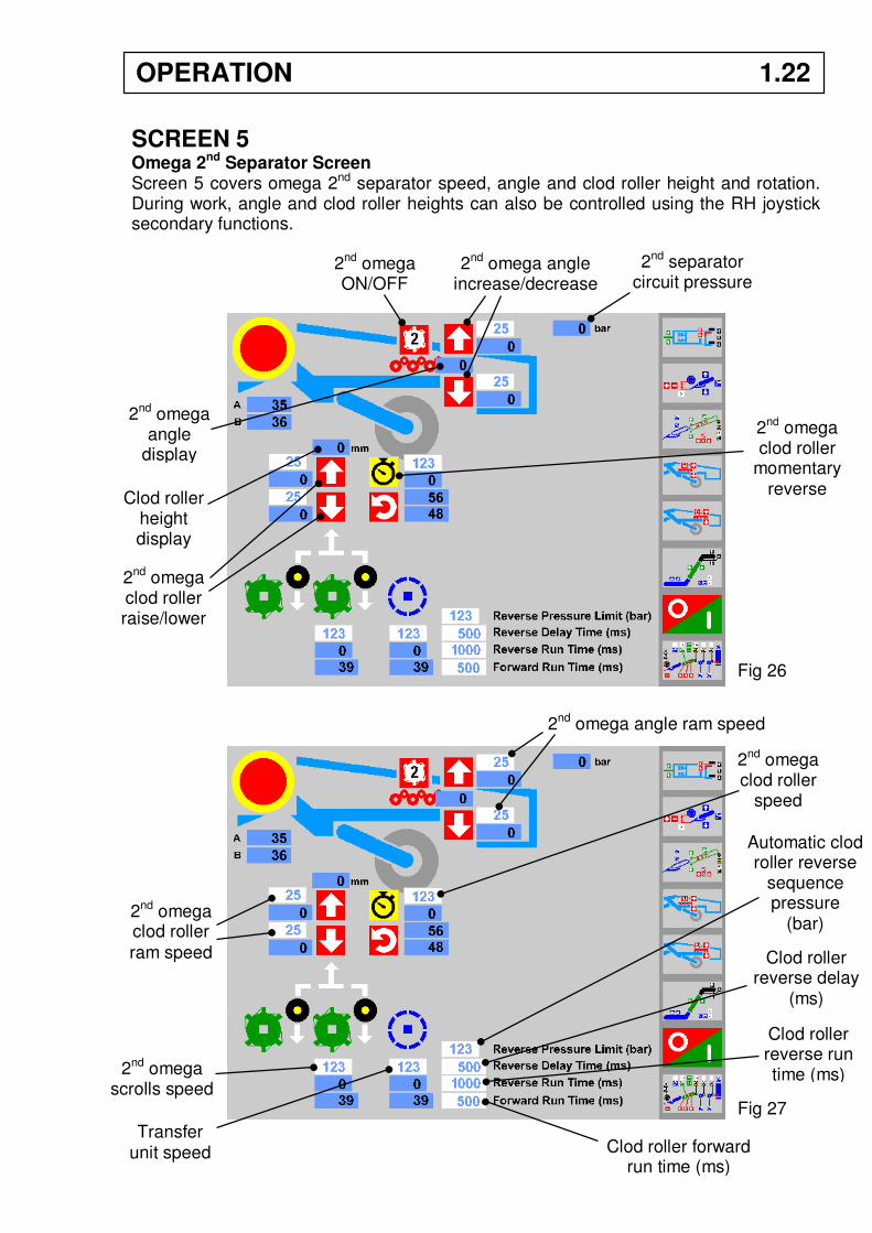
SCREEN 5
Omega 2nd Separator Screen Screen 5 covers omega 2nd separator speed, angle and clod roller height and rotation. During work, angle and clod roller heights can also be controlled using the RH joystick secondary functions.
2nd omega ON/OFF
2nd omega angle increase/decrease
2nd omega clod roller raise/lower
2nd omega clod roller
momentary reverse
2nd omega angle
display
2nd omega angle ram speed
2nd omega clod roller
speed
2nd omega clod roller
ram speed
Transfer unit speed
2nd omega scrolls speed
Fig 26
Fig 27
Clod roller height display
OPERATION 1.22
2nd separator circuit pressure
Automatic clod roller reverse
sequence pressure
(bar)
Clod roller reverse delay
(ms)
Clod roller reverse run time (ms)
Clod roller forward run time (ms)
Automatic clod roller reverse pressure During harvesting it may be necessary to change the pressure at which the rollers reverse. The automatic reverse sequence is triggered by a pressure transducer that senses the operating pressure within the system. Increase or decrease the reverse pressure in small steps until the required operation is achieved. Roller reverse delay Sets the time delay in milliseconds before triggering the reverse sequence. (1000 milliseconds = 1 second). Roller reverse run time Sets the length of time in milliseconds that the rollers run in reverse mode when clearing a blockage. Roller forward run time Sets the length of time in milliseconds that the rollers run in forward mode before reversing again if the blockage is still present. Momentary roller reverse Starts the reverse sequence to allow stones and trash seen by the operator to be ejected before a blockage occurs.
1.23 OPERATION
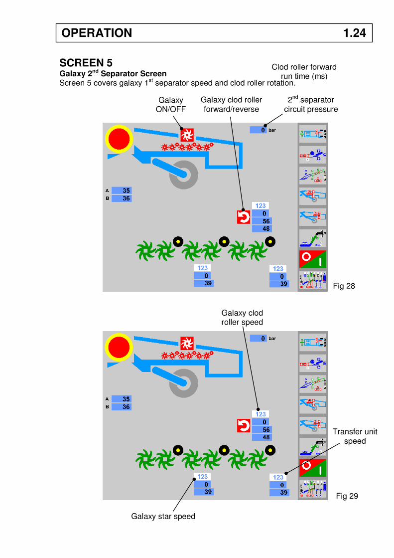
SCREEN 5
Galaxy 2nd Separator Screen Screen 5 covers galaxy 1st separator speed and clod roller rotation.
Galaxy ON/OFF
Galaxy clod roller forward/reverse
Galaxy star speed
Galaxy clod roller speed
Transfer unit speed
Fig 28
Fig 29
2nd separator circuit pressure
Clod roller forward run time (ms)
OPERATION 1.24
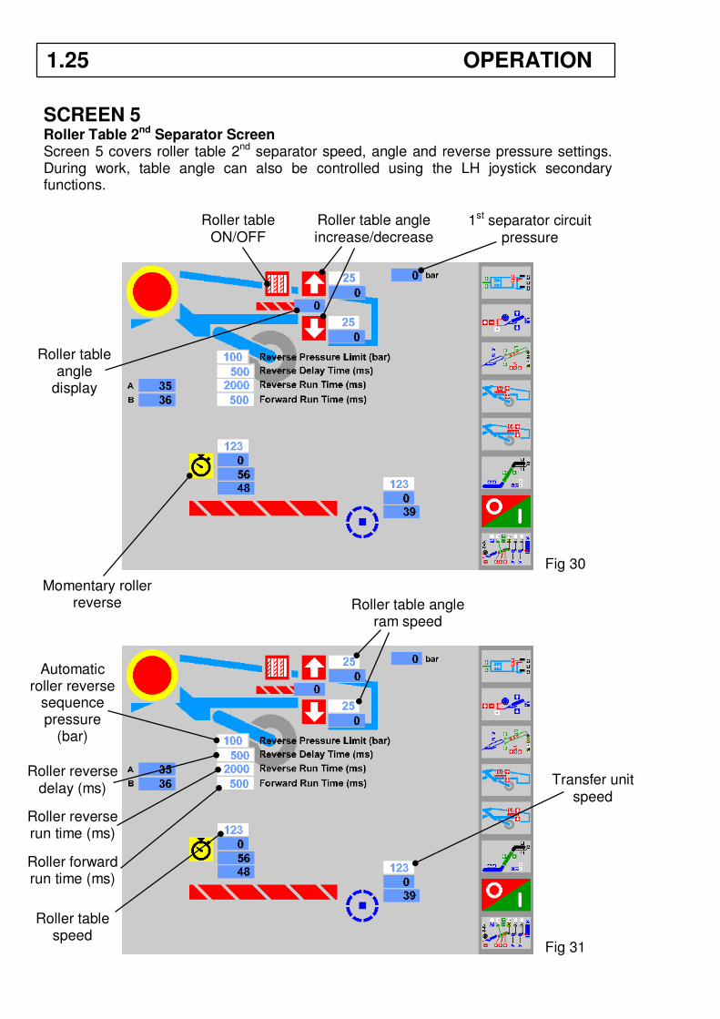
SCREEN 5 Roller Table 2nd Separator Screen Screen 5 covers roller table 2nd separator speed, angle and reverse pressure settings. During work, table angle can also be controlled using the LH joystick secondary functions.
Roller table ON/OFF
Roller table angle increase/decrease
Momentary roller reverse
Roller table angle
display
Fig 30
Transfer unit speed
Roller table angle ram speed
Roller table speed
Automatic roller reverse
sequence pressure
(bar)
Roller reverse delay (ms)
Roller reverse run time (ms)
Roller forward run time (ms)
Fig 31
1st separator circuit pressure
1.25 OPERATION
Automatic roller table reverse pressure During harvesting it may be necessary to change the pressure at which the rollers reverse. The automatic reverse sequence is triggered by a pressure transducer that senses the operating pressure within the system. Increase or decrease the reverse pressure in small steps until the required operation is achieved. Roller reverse delay Sets the time delay in milliseconds before triggering the reverse sequence. (1000 milliseconds = 1 second). Roller reverse run time Sets the length of time in milliseconds that the rollers run in reverse mode when clearing a blockage. Roller forward run time Sets the length of time in milliseconds that the rollers run in forward mode before reversing again if the blockage is still present. Momentary roller reverse Starts the reverse sequence to allow stones and trash seen by the operator to be ejected before a blockage occurs.
OPERATION 1.26
SCREEN 6 Spreader / Table and Elevator Screen During work, elevator fold and swan neck height can be controlled using the RH joystick.
Spreader/picking table ON/OFF
Swan neck raise
Swan neck auto-height
ON/OFF Elevator centre section
in/out
Elevator base section in/out
(T3 only)
Windrow ON/OFF
Elevator web ON/OFF
Fig 32
Communication buzzer
Spreader/picking table speed
Swan neck ram speed
Elevator base section ram speed
(T3 only)
Elevator web speed
Fig 33
Swan neck lower
Tractor powered circuit pressure
Elevator centre section
ram speed
1.27 OPERATION
SCREEN 7 Programming Screen Screen 7 covers save/load speed program, headland start/stop sequence programming and restore system default settings.
Speed programs The ideal speed set-up for harvesting conditions in different parts of a field can be saved by the operator using the SAVE SPEED PROGRAM buttons. The speed, angle and height settings of all the harvester elements are saved. To save the present harvester settings press . Pressing the save button will overwrite any previous settings saved under that button. To reload the saved settings press . Three individual speed programs can be set.
Save speed
program
Load speed
program
Restore default settings
Headland START sequence
options
Headland STOP sequence
options
Record sequence
Record sequence
RUN start sequence
RUN stop sequence
Digger raise time
(s)
Fig 34
OPERATION 1.28
Headland START and STOP sequences A headland start sequence and stop sequence can be recorded into the system to automatically start/stop the elements and lift the digger out of work. To program the START sequence In the START options area: 1. Press the start RECORD button . 2. In real time, select the elements in the order you want them to start. 3. Press the record STOP button . 4. The START sequence is recorded into the memory. To program the STOP sequence In the STOP options area: 1. Press the record START button . 2. In real time, select the elements in the order you want them to STOP. 3. Press the record STOP button . 4. The STOP sequence is recorded into the memory. Note: If the digger raise button has been selected in the STOP sequence, the
digger raise time parameter should be set. Usually, 5 seconds in raise is sufficient for the digger to clear the bed.
Press to run the START sequence. Press to run the STOP sequence. During work, the headland program sequences can be run using the red rocker switch on the slave box.
1.29 OPERATION
ESC (x1) Machine Configuration Screen Pressing the ESC button once displays the machine configuration screen. This screen covers machine type (T2 or T3), 1st & 2nd separator type and icon selection for optional equipment. These settings must be configured to your machine for the screens to display and function correctly. Main Page Icon Configuration The icons in this area allow the operator to select optional equipment fitted to the machine. When selected they will display on the main screen (<< 8). Powered diabolo , clod fingers , elevator auto-height , auto-machine level , windrow .
Select machine type
Machine type display
(1) Elevator ON/OFF
or (2) elevator &
spreader/picking table ON/OFF
Screen brightness
Additional main page icons for
optional equipment
LH joystick configuration
RH joystick configuration
Main elements ON
1st separator type
2nd separator type
Fig 35
Rear control box ON/OFF
(manned only)
OPERATION 1.30
Main Page Master ON The elements in this area can be selected to start simultaneously. Pressing the ‘MAIN ELEMENTS ON’ button on the main screen (<< 8) will start the selected elements. Discharge/Spreader Icon Configuration The elevator ON/OFF icon can be configured to one of these settings: Setting (1): Switches the elevator ON/OFF only. Setting (2): Switches the elevator and spreader/picking table ON/OFF simultaneously. Left/Right Joystick Configuration Allows the operator to choose preferred joystick axis settings. X-axis = left/right. Y-axis = up/down. Select the function you wish to operate on the LH joystick X-axis,
drawbar steer or axle steer.
The Y-axis defaults to the other function. Direction of movement can be reversed by pressing the button . Select the function you wish to operate on the RH joystick X-axis, swan neck or elevator fold. The Y-axis defaults to the other function. Direction of movement can be reversed by pressing the button . 1st Unit Configuration Selects the 1st separator fitted to the machine. Omega, starflow or roller table. 2nd Unit Configuration Selects the 2nd separator fitted to the machine. Omega, galaxy or roller table. Back Box ON/OFF On manned machines, a control box is fitted above the picking table allowing the pickers to adjust the picking table speed and axle level etc. If necessary, the control buttons can be isolated using the back box ON/OFF button. The emergency stop buttons remain active.
1.31 OPERATION
ESC (x2) Program Information Screen
Pressing the ESC button twice displays the program version and date.
Fig 36
OPERATION 1.32
Slave Box Functions Along with the touch-screen terminal, all commonly used controls are repeated on the slave box. Slave box switch functions are: Item 1 - Touch-screen terminal ON/OFF. Item 2 - Start switch for machine control module. Item 3 - Headland program start/stop sequence. Item 4 - Digger auto-lower/off/manual raise. Item 5 - Powered axle drive forward/off/reverse. Item 6 - Agitation ON/OFF. Item 7 - Web split (VariSep) raise/lower. Item 8 - Machine level raise/lower.
Slave box joystick functions are: Item 9 - LH Joystick default functions: Drawbar steer.
Axle steer. Item 10 - Axle auto-centre. Item 11 - LH Joystick secondary functions: 1st separator clod roller height.
1st separator angle. Item 12 - RH Joystick default functions: Elevator fold in/out.
Swan neck raise/lower. Item 13 - Elevator ON/OFF. Item 14 - RH Joystick secondary functions: 2nd separator clod roller height.
2nd separator angle.
Where slave box functions are duplicates of buttons on the touch-screen terminal, the button on the touch-screen will be highlighted when the slave box switch is operated.
Fig 37 Fig 38
1.33 OPERATION
LH joystick functions LH joystick default functions are drawbar steer and axle steer. LH joystick secondary functions are 1st separator clod roller height and 1st separator angle. To activate the secondary functions, press and hold the button (item 11, fig 39). Re-centre the joystick before releasing the button. Note: If the LH joystick fails to operate, centre the joystick and press the secondary
function button (item 11, fig 39) once to reactivate it.
RH joystick functions RH joystick default functions are elevator fold in/out and swan neck raise/lower. RH joystick secondary functions are 2nd separator clod roller height and 2nd separator angle. To activate the secondary functions, press and hold the button (item 14, fig 39). Re-centre the joystick before releasing the button. Note: If the RH joystick fails to operate, centre the joystick and press the secondary function button (item 14, fig 39) once to reactivate it.
Fig 39
OPERATION 1.34
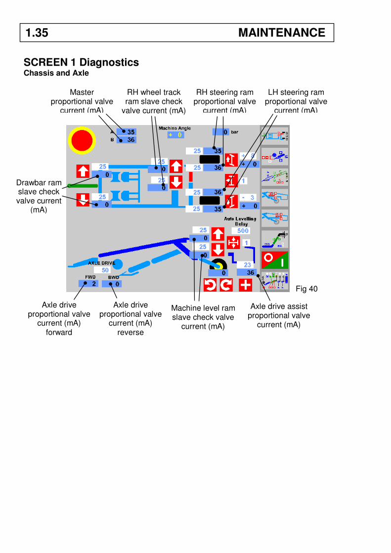
SCREEN 1 Diagnostics Chassis and Axle
Master proportional valve
current (mA)
RH steering ram proportional valve
current (mA)
LH steering ram proportional valve
current (mA)
RH wheel track ram slave check
valve current (mA)
Axle drive proportional valve
current (mA) forward
Axle drive proportional valve
current (mA) reverse
Machine level ram slave check valve
current (mA)
Axle drive assist proportional valve
current (mA)
Drawbar ram slave check valve current
(mA)
1.35 MAINTENANCE
Fig 40
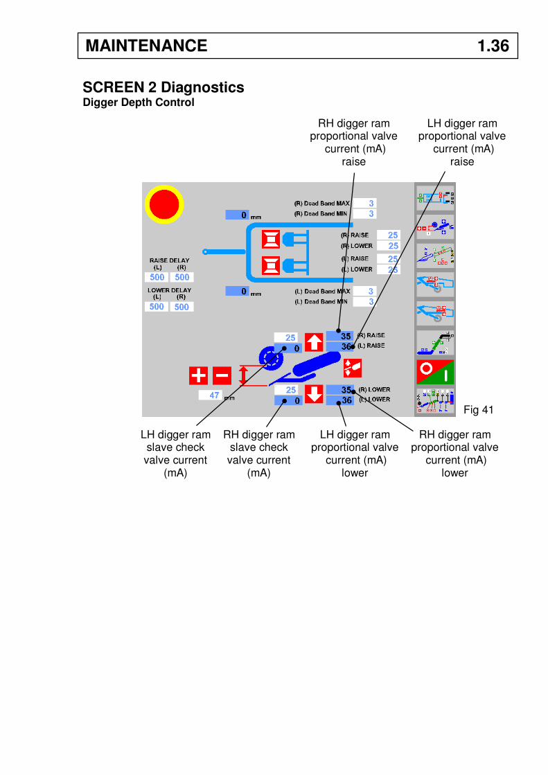
SCREEN 2 Diagnostics Digger Depth Control
LH digger ram slave check valve current
(mA)
RH digger ram slave check valve current
(mA)
RH digger ram proportional valve
current (mA) raise
LH digger ram proportional valve
current (mA) lower
RH digger ram proportional valve
current (mA) lower
Fig 41
LH digger ram proportional valve
current (mA) raise
MAINTENANCE 1.36
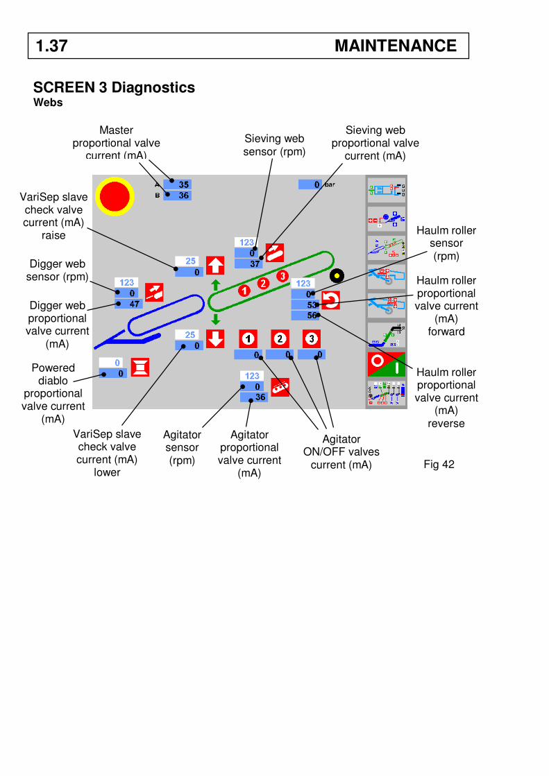
SCREEN 3 Diagnostics Webs
Master proportional valve
current (mA)
Digger web sensor (rpm)
Digger web proportional valve current
(mA)
Sieving web proportional valve
current (mA)
VariSep slave check valve current (mA)
raise
VariSep slave check valve current (mA)
lower
Sieving web sensor (rpm)
Agitator proportional valve current
(mA)
Agitator sensor (rpm)
Agitator ON/OFF valves
current (mA)
Haulm roller proportional valve current
(mA) forward
Haulm roller proportional valve current
(mA) reverse
Haulm roller sensor (rpm)
1.37 MAINTENANCE
Fig 42
Powered diablo
proportional valve current
(mA)
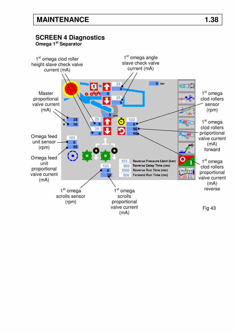
SCREEN 4 Diagnostics Omega 1st Separator
1st omega angle slave check valve
current (mA)
1st omega clod roller height slave check valve
current (mA)
Master proportional valve current
(mA)
1st omega clod rollers
sensor (rpm)
1st omega clod rollers proportional valve current
(mA) forward
1st omega clod rollers proportional valve current
(mA) reverse
Omega feed unit sensor
(rpm)
Omega feed unit
proportional valve current
(mA)
1st omega scrolls sensor
(rpm)
1st omega scrolls
proportional valve current
(mA) Fig 43
MAINTENANCE 1.38
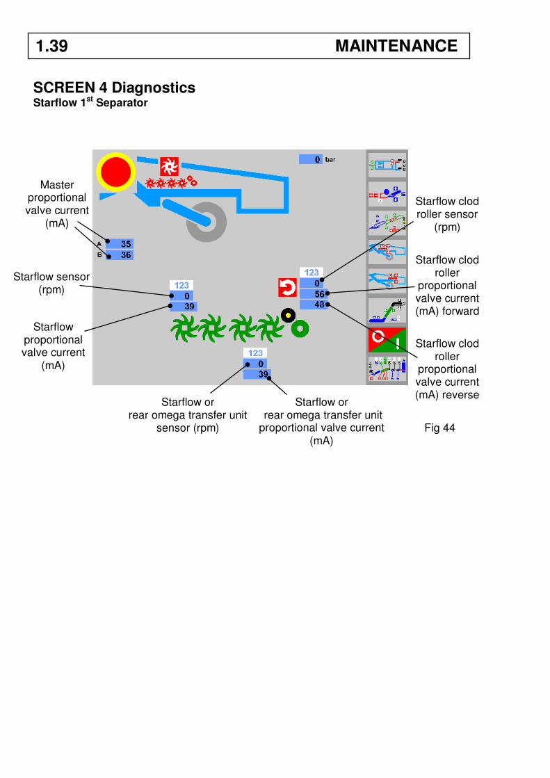
SCREEN 4 Diagnostics Starflow 1st Separator
Master proportional valve current
(mA)
Starflow sensor (rpm)
Starflow or rear omega transfer unit
sensor (rpm)
Starflow or rear omega transfer unit proportional valve current
(mA)
Starflow clod roller sensor
(rpm)
Starflow clod roller
proportional valve current (mA) forward
Starflow clod roller
proportional valve current (mA) reverse
Starflow proportional valve current
(mA)
Fig 44
1.39 MAINTENANCE
SCREEN 4 Diagnostics Roller Table 1st Separator
Roller table angle slave check valve
current (mA)
Feed unit sensor (rpm)
Feed unit proportional valve current
(mA)
Roller table
(rpm)
Roller table proportional valve current
(mA) forward
Roller table proportional valve current
(mA) reverse
Master proportional valve current
(mA)
MAINTENANCE 1.40
Fig 45
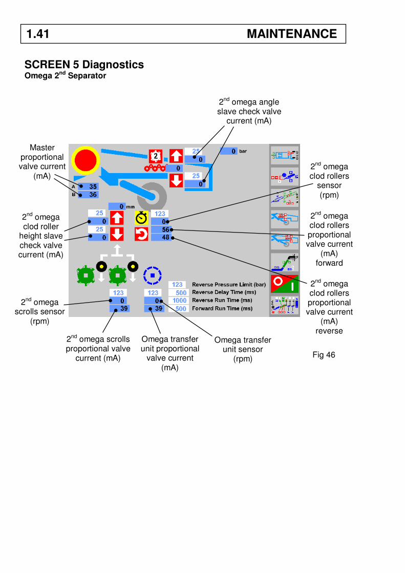
SCREEN 5 Diagnostics Omega 2nd Separator
Master proportional valve current
(mA)
2nd omega angle slave check valve
current (mA)
2nd omega clod roller
height slave check valve current (mA)
2nd omega clod rollers
sensor (rpm)
2nd omega clod rollers proportional valve current
(mA) forward
2nd omega clod rollers proportional valve current
(mA) reverse
2nd omega scrolls sensor
(rpm)
2nd omega scrolls proportional valve
current (mA)
Omega transfer unit sensor
(rpm)
Omega transfer unit proportional
valve current (mA)
1.41 MAINTENANCE
Fig 46
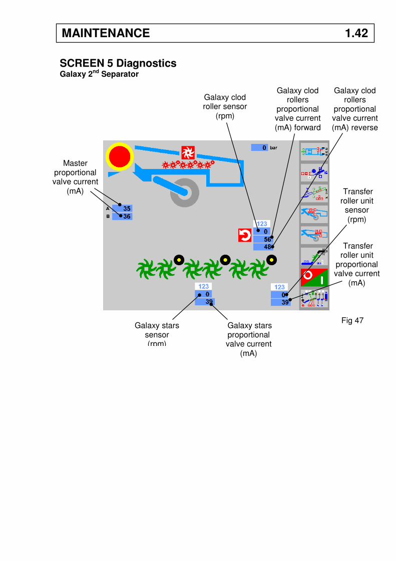
SCREEN 5 Diagnostics Galaxy 2nd Separator
Master proportional valve current
(mA)
Galaxy clod roller sensor
(rpm)
Galaxy clod rollers
proportional valve current (mA) forward
Galaxy clod rollers
proportional valve current (mA) reverse
Transfer roller unit
sensor (rpm)
Transfer roller unit
proportional valve current
(mA)
Galaxy stars proportional valve current
(mA)
Galaxy stars sensor (rpm)
MAINTENANCE 1.42
Fig 47
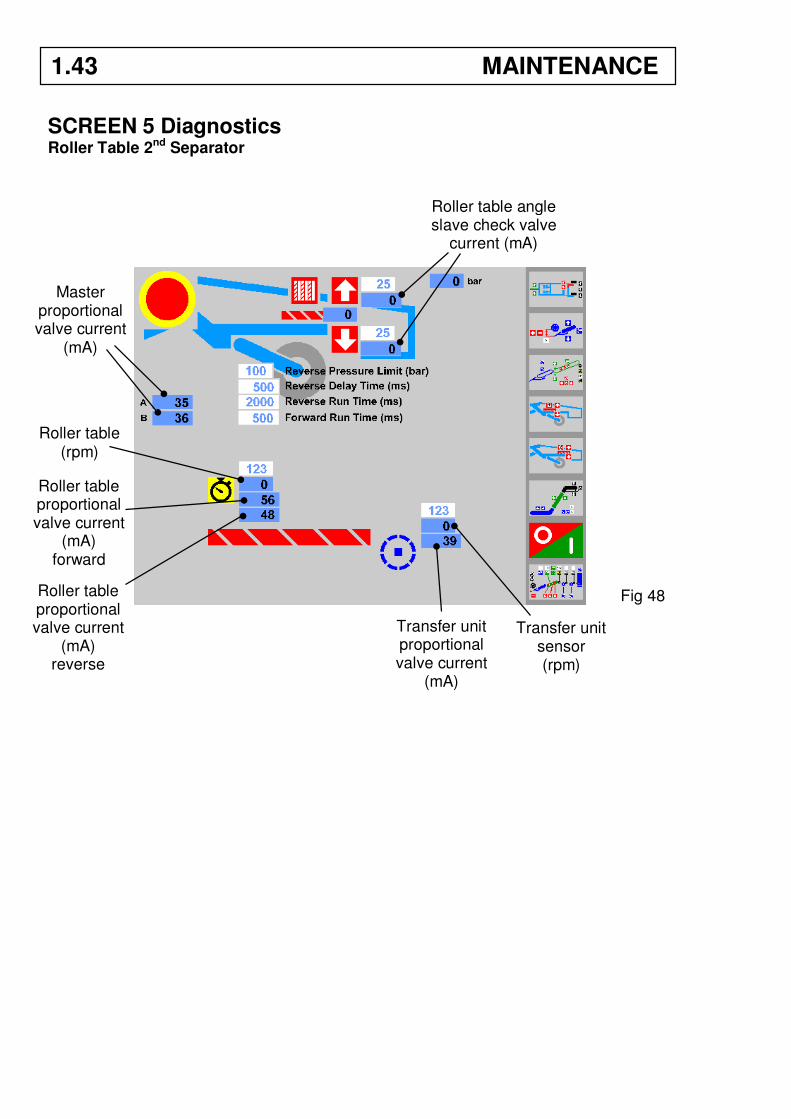
SCREEN 5 Diagnostics Roller Table 2nd Separator
1.43 MAINTENANCE
Roller table angle slave check valve
current (mA)
Transfer unit sensor (rpm)
Transfer unit proportional valve current
(mA)
Roller table (rpm)
Roller table proportional valve current
(mA) forward
Roller table proportional valve current
(mA) reverse
Master proportional valve current
(mA)
Fig 48
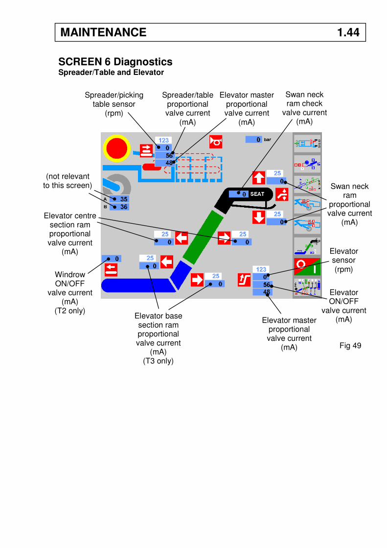
SCREEN 6 Diagnostics Spreader/Table and Elevator
Spreader/picking table sensor
(rpm)
Spreader/table proportional valve current
(mA)
Elevator master proportional valve current
(mA)
(not relevant to this screen)
Windrow ON/OFF
valve current (mA)
(T2 only) Elevator base section ram proportional valve current
(mA) (T3 only)
Elevator centre section ram proportional valve current
(mA)
Elevator sensor (rpm)
Elevator master proportional valve current
(mA)
Elevator ON/OFF
valve current (mA)
Swan neck ram
proportional valve current
(mA)
Swan neck ram check
valve current (mA)
Fig 49
MAINTENANCE 1.44
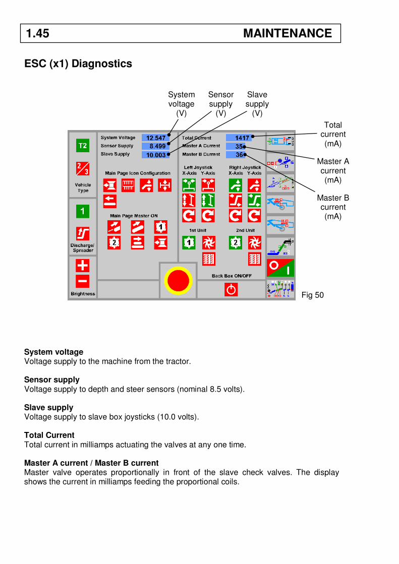
ESC (x1) Diagnostics
System voltage Voltage supply to the machine from the tractor. Sensor supply Voltage supply to depth and steer sensors (nominal 8.5 volts). Slave supply Voltage supply to slave box joysticks (10.0 volts). Total Current Total current in milliamps actuating the valves at any one time. Master A current / Master B current Master valve operates proportionally in front of the slave check valves. The display shows the current in milliamps feeding the proportional coils.
Fig 50
System voltage
(V)
Sensor supply
(V)
Slave supply
(V)
Total current (mA)
Master A current (mA)
Master B current (mA)
1.45 MAINTENANCE
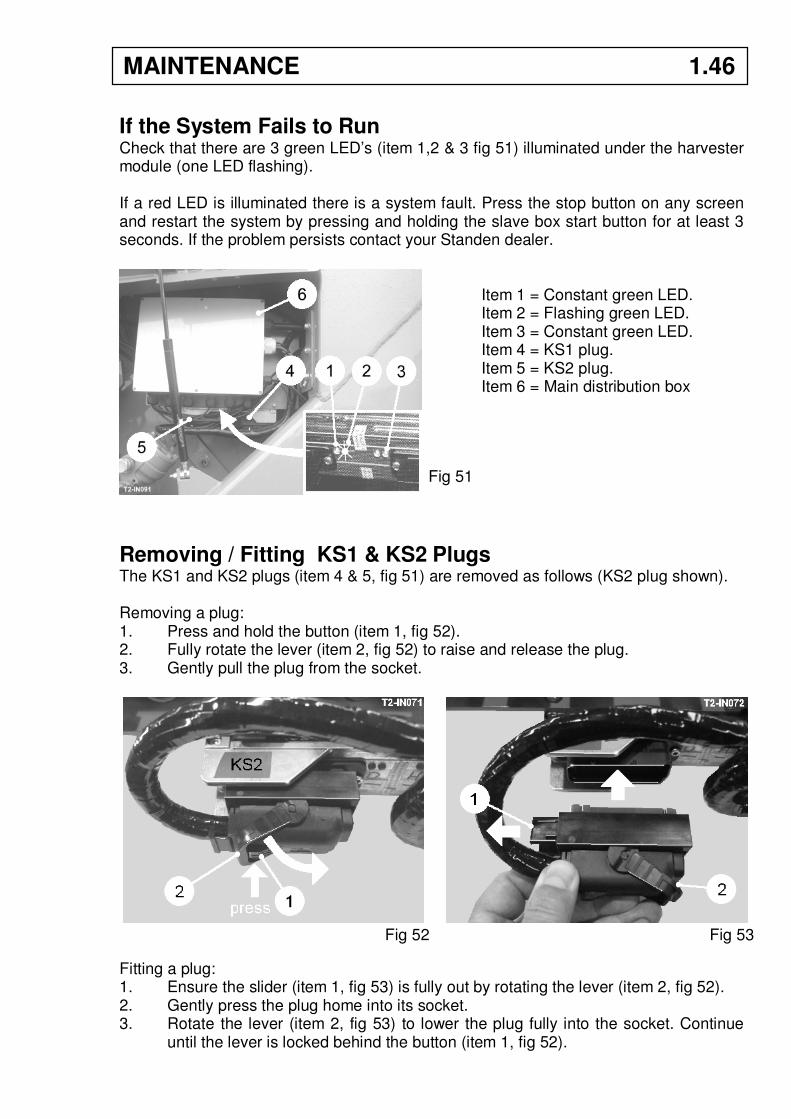
If the System Fails to Run Check that there are 3 green LED’s (item 1,2 & 3 fig 51) illuminated under the harvester module (one LED flashing). If a red LED is illuminated there is a system fault. Press the stop button on any screen and restart the system by pressing and holding the slave box start button for at least 3 seconds. If the problem persists contact your Standen dealer.
Item 1 = Constant green LED. Item 2 = Flashing green LED. Item 3 = Constant green LED. Item 4 = KS1 plug. Item 5 = KS2 plug. Item 6 = Main distribution box
Removing / Fitting KS1 & KS2 Plugs The KS1 and KS2 plugs (item 4 & 5, fig 51) are removed as follows (KS2 plug shown). Removing a plug: 1. Press and hold the button (item 1, fig 52). 2. Fully rotate the lever (item 2, fig 52) to raise and release the plug. 3. Gently pull the plug from the socket.
Fitting a plug: 1. Ensure the slider (item 1, fig 53) is fully out by rotating the lever (item 2, fig 52). 2. Gently press the plug home into its socket. 3. Rotate the lever (item 2, fig 53) to lower the plug fully into the socket. Continue
until the lever is locked behind the button (item 1, fig 52).
Fig 51
Fig 52 Fig 53
MAINTENANCE 1.46
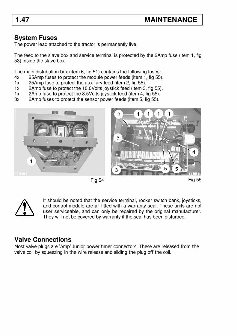
System Fuses The power lead attached to the tractor is permanently live. The feed to the slave box and service terminal is protected by the 2Amp fuse (item 1, fig 53) inside the slave box. The main distribution box (item 6, fig 51) contains the following fuses: 4x 25Amp fuses to protect the module power feeds (item 1, fig 55). 1x 25Amp fuse to protect the auxiliary feed (item 2, fig 55). 1x 2Amp fuse to protect the 10.0Volts joystick feed (item 3, fig 55). 1x 2Amp fuse to protect the 8.5Volts joystick feed (item 4, fig 55). 3x 2Amp fuses to protect the sensor power feeds (item 5, fig 55).
It should be noted that the service terminal, rocker switch bank, joysticks, and control module are all fitted with a warranty seal. These units are not user serviceable, and can only be repaired by the original manufacturer. They will not be covered by warranty if the seal has been disturbed.
Valve Connections Most valve plugs are ‘Amp’ Junior power timer connectors. These are released from the valve coil by squeezing in the wire release and sliding the plug off the coil.
Fig 54 Fig 55
1.47 MAINTENANCE

CIRCUIT DIAGRAMS ESX-3XL Controller Plug Pin Allocation 2.1 Machine Lighting Layout 2.3 Slave Box General Assembly 2.4 Slave Box Board 2.5 CAN-BUS Distribution Board 2.6 Distribution Box Loom 2.7 Left-hand Loom 2.8 Main Valve Loom 2.9 Display Loom 2.10 Cab Loom 2.11
CONTENTS
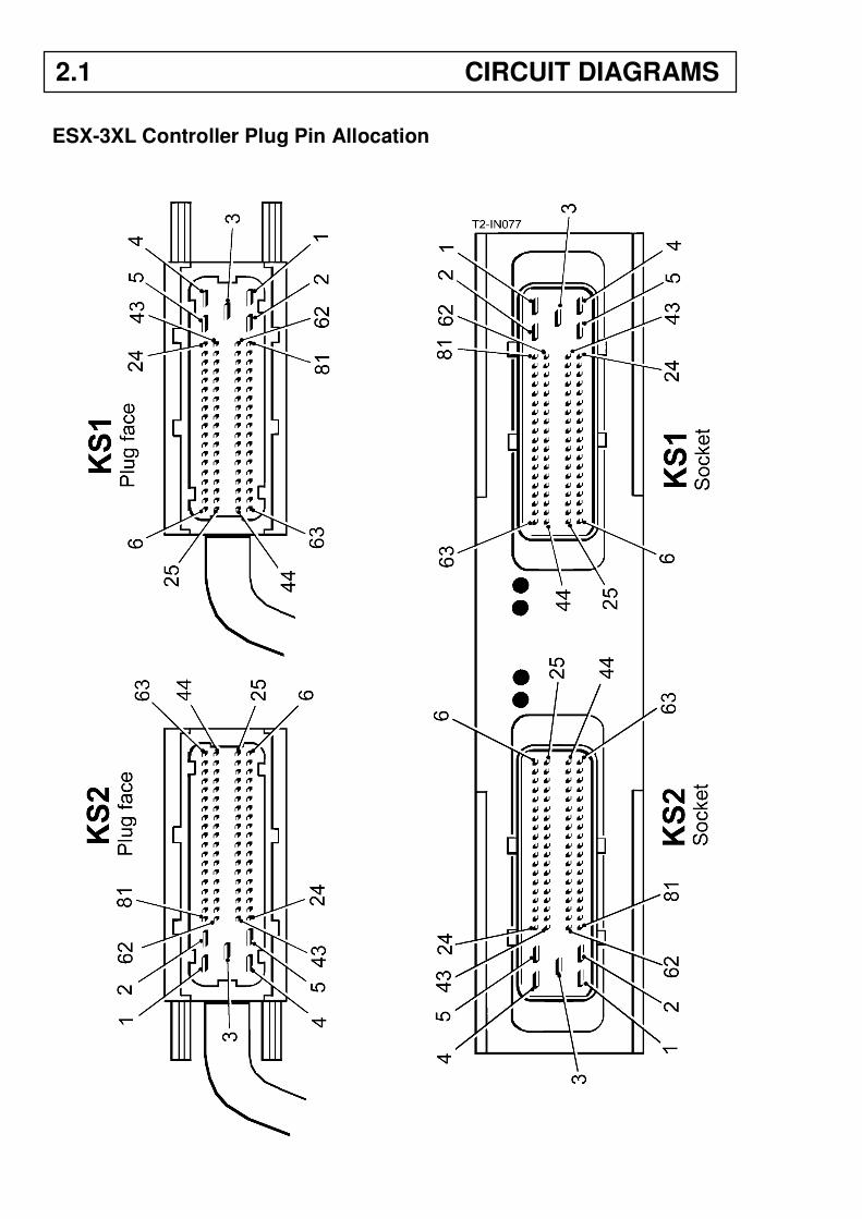
ESX-3XL Controller Plug Pin Allocation
2.1 CIRCUIT DIAGRAMS
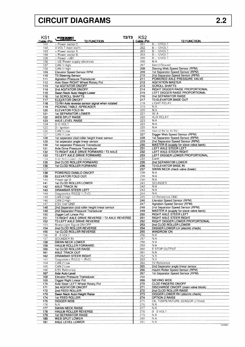
CIRCUIT DIAGRAMS 2.2
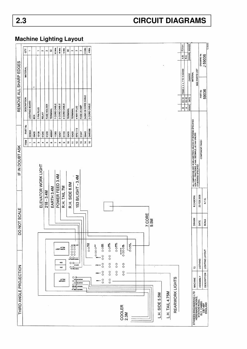
Machine Lighting Layout
2.3 CIRCUIT DIAGRAMS
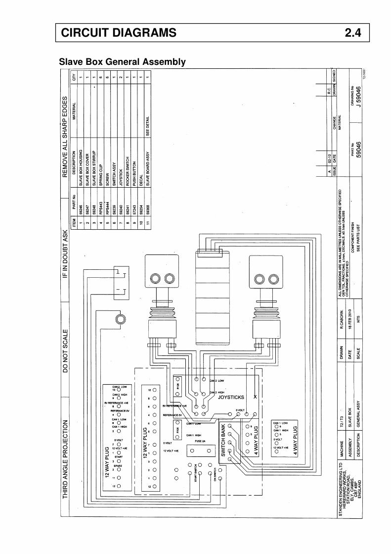
Slave Box General Assembly
CIRCUIT DIAGRAMS 2.4
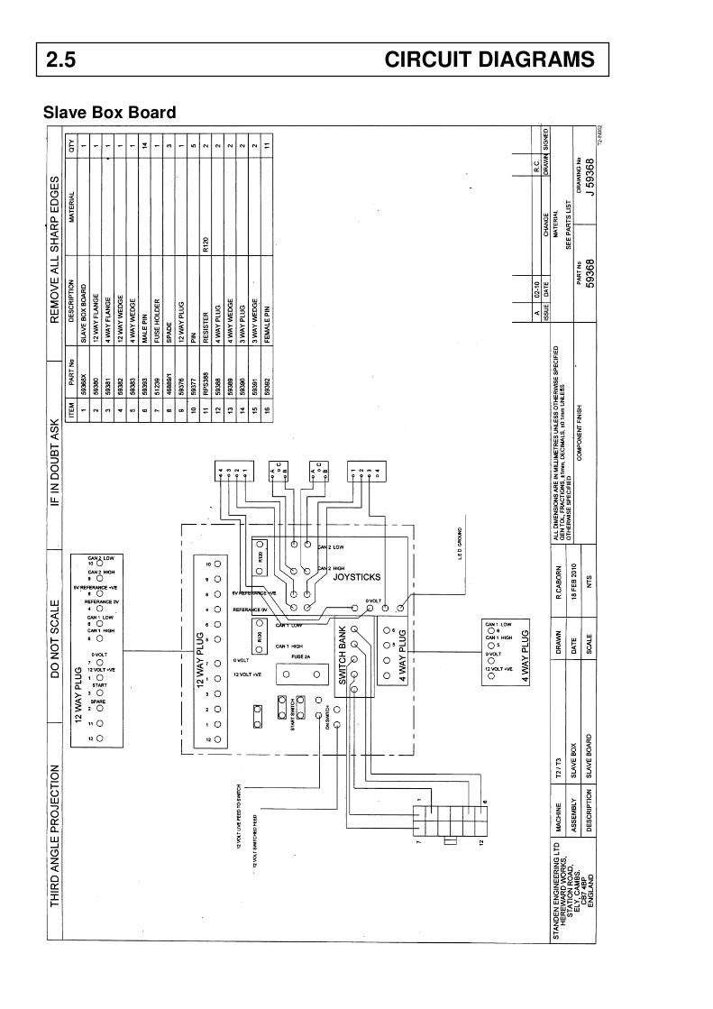
Slave Box Board
2.5 CIRCUIT DIAGRAMS
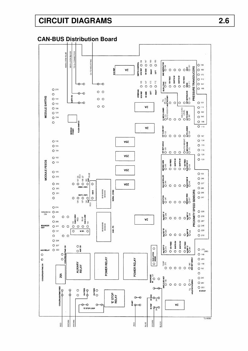
CAN-BUS Distribution Board
CIRCUIT DIAGRAMS 2.6
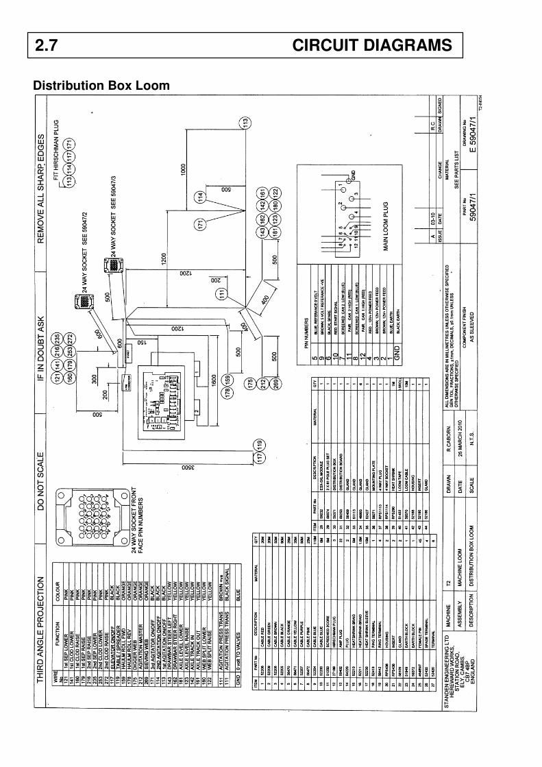
Distribution Box Loom
2.7 CIRCUIT DIAGRAMS
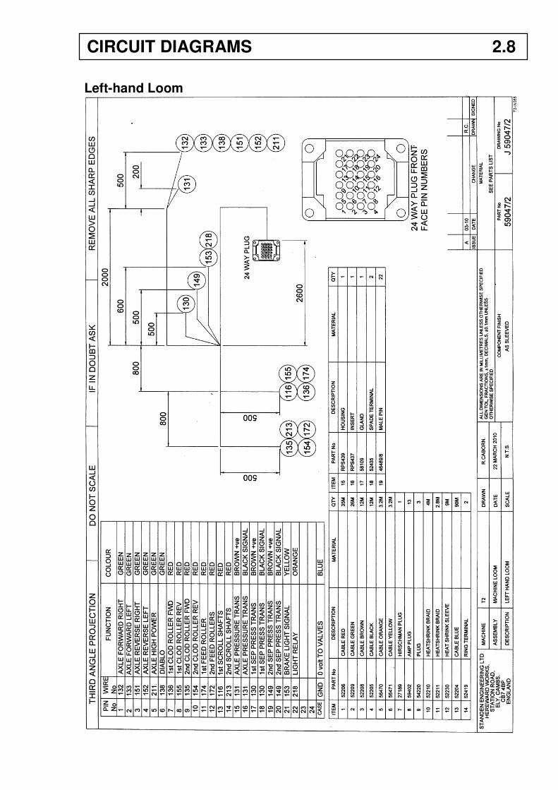
Left-hand Loom
CIRCUIT DIAGRAMS 2.8
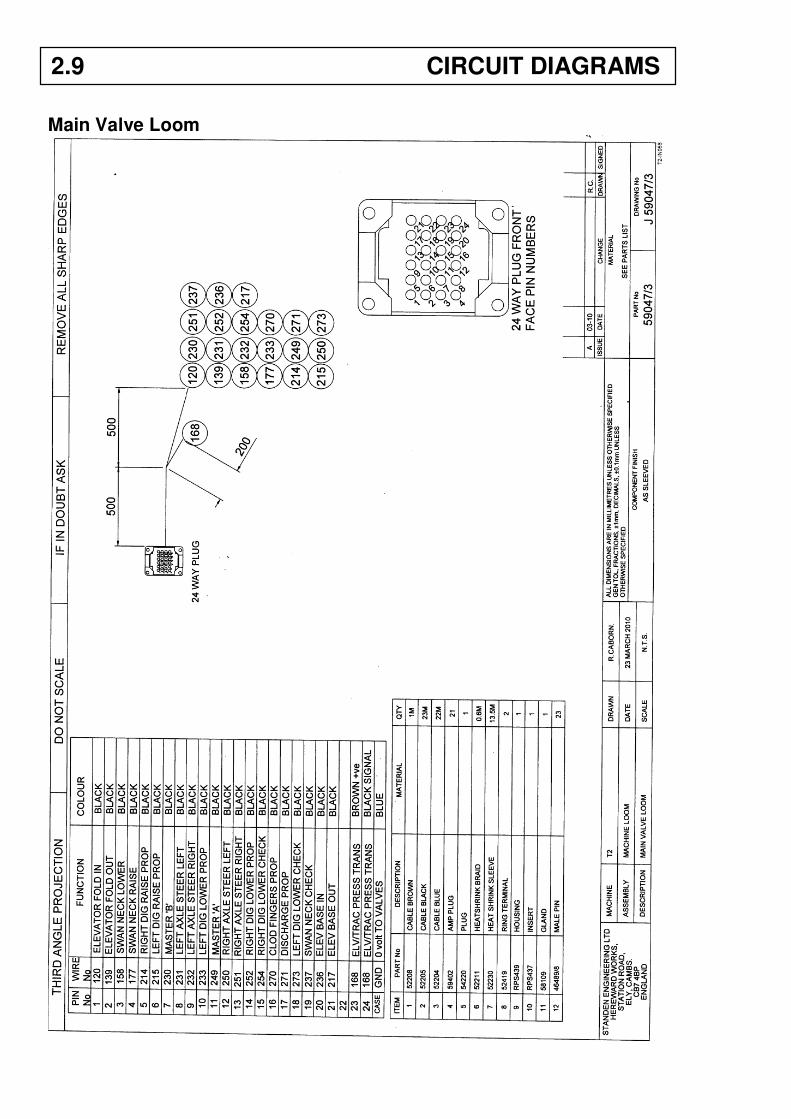
Main Valve Loom
2.9 CIRCUIT DIAGRAMS
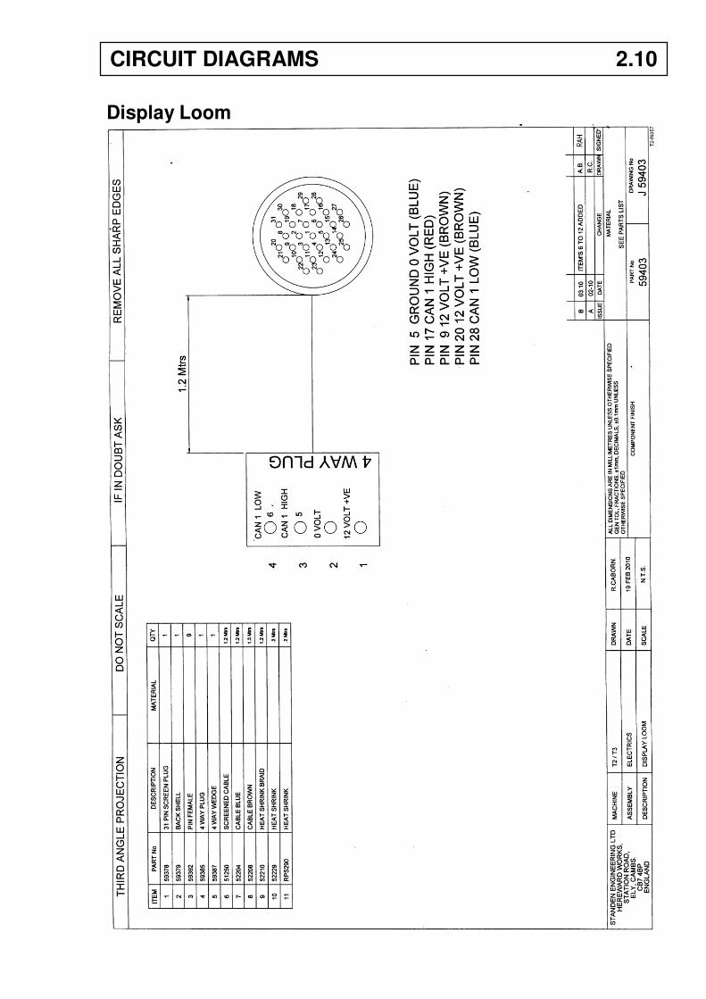
Display Loom
CIRCUIT DIAGRAMS 2.10
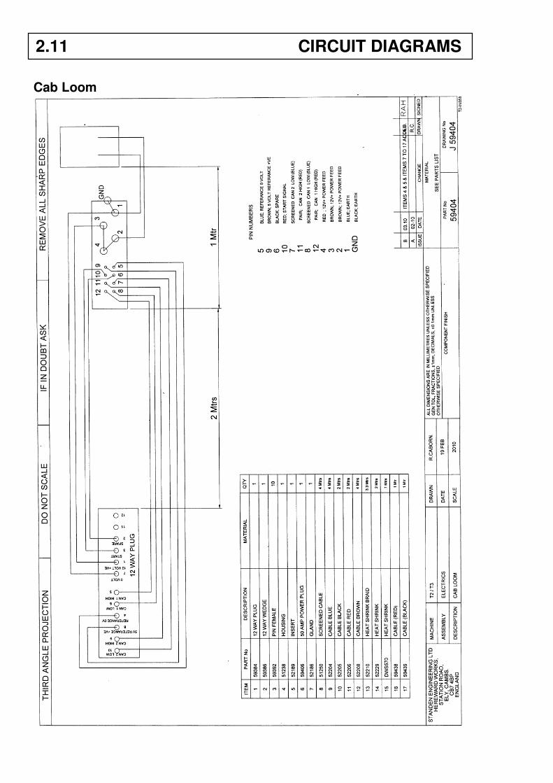
Cab Loom
2.11 CIRCUIT DIAGRAMS