T2--PHP, T2--NHP LEGACY THERMOSTATS...
40
Installation Instructions T2--PAC, T2--NAC T2--PHP, T2--NHP LEGACYt SERIES THERMOSTATS A07047 A07046 Legacy Series Legacy Series Programmable Thermostat Non-Programmable Thermostat Designed and Assembled in the U.S.A. NOTE: Read the entire instruction manual before starting the installation. US patents: US20060165149 A1, USD582803 SI, USD582802 SI
Transcript of T2--PHP, T2--NHP LEGACY THERMOSTATS...
Installation Instructions
T2--PAC, T2--NACT2--PHP, T2--NHPLEGACYt SERIESTHERMOSTATS
A07047 A07046
Legacy Series Legacy SeriesProgrammable Thermostat Non--Programmable Thermostat
Designed andAssembled in the U.S.A.
NOTE: Read the entire instruction manual before starting the installation.US patents: US20060165149 A1, USD582803 SI, USD582802 SI


1
TABLE OF CONTENTSPAGE
SAFETY CONSIDERATIONS 2. . . . . . . . . . . . . . . . . . . . . . . . . . . . . . . .
INSTALLATION CONSIDERATIONS 4. . . . . . . . . . . . . . . . . . . . . . . . . .
INSTALLATION 5. . . . . . . . . . . . . . . . . . . . . . . . . . . . . . . . . . . . . . . . . . .
Step 1 — Thermostat Location 5. . . . . . . . . . . . . . . . . . . . . . . . . . . . . . .
Step 2 — Install Thermostat 5. . . . . . . . . . . . . . . . . . . . . . . . . . . . . . . . . .
Step 3 — Set Thermostat Configuration 10. . . . . . . . . . . . . . . . . . . . . . .
Step 4 — Check Thermostat Operation 18. . . . . . . . . . . . . . . . . . . . . . . .
FEATURES AND ACCESSORIES 20. . . . . . . . . . . . . . . . . . . . . . . . . . . .
OPERATIONAL AND CONNECTION INFORMATION 22. . . . . . . . . .
WIRING DIAGRAMS 25. . . . . . . . . . . . . . . . . . . . . . . . . . . . . . . . . . . . . .
THERMOSTAT CONFIGURATION RECORD 32. . . . . . . . . . . . . . . . . .
2
SAFETY CONSIDERATIONSRead and follow manufacturer instructions carefully. Follow all local electricalcodes during installation. All wiring must conform to local and national electricalcodes. Improper wiring or installation may damage thermostat.
Recognize safety information. This is the safety--alert symbol . When you seethis symbol on the equipment and in the instruction manual, be alert to the potentialfor personal injury.
Understand the signal words DANGER, WARNING, and CAUTION. Thesewords are used with the safety--alert symbol. DANGER identifies the most serioushazards which will result in severe personal injury or death.WARNING signifies ahazard which could result in personal injury or death. CAUTION is used to identifyunsafe practices which may result in minor personal injury or product and propertydamage. NOTE is used to highlight suggestions which will result in enhancedinstallation, reliability, or operation.
3
INTRODUCTIONBryant’s Legacyt Series programmable thermostats are wall--mounted,low--voltage thermostats which maintain room temperature by controlling theoperation of a heating and/or air conditioning system. Both heat pump and airconditioner models are available, each in programmable and non--programmableversions. A variety of features are provided including battery operation, separateheating and cooling setpoints, auto changeover, keypad lockout, backlighting, andbuilt--in installer test. Programming features include 7--day (all days the same) and5/2 (Mon--Fri and Sat--Sun) with 2 or 4 periods per day.
This Installation Instruction covers installation, configuration, and start--up of allfour versions of the Legacy Series line of thermostats. For operational details,consult the Owner’s Manual for the specific thermostat you are installing.
4
INSTALLATION CONSIDERATIONSModelsThere are four models in the Legacy Series: programmable and non--programmable, ACand HP. Models T2--PAC and T2--NAC are designed for AC systems, controlling onestage of cooling and one stage of heating. They will not operate a heat pump. ModelsT2--PHP and T2--NHP are designed for HP systems, controlling two stages of coolingand three stages of heating. They can be converted to AC operation. Select theappropriate model for the intended application.
PowerAll Legacy Series models are dual powered. They can operate from batteries or24VAC power. Operation from 24VAC is preferred if available. Battery operation isused when there are not enough wires to support 24VAC operation or when“armchair programming” is desired. For an AC system, up to six wires are neededfor 24VAC operation and one less wire for battery operation. For a HP system, up toseven wires are needed for 24VAC operation and and one less wire is sufficient forbattery operation. For heat only operation with batteries, only two wires arerequired. When battery operation is used, the C terminal does not need to beconnected.
Provision is also made for separate heating and cooling transformers via separable Rcand Rh terminals which are connected via factory--installed jumper wire.
5
INSTALLATIONInstallation Notes:
S The maximum wire size to be used in the installation is 22AWG(0.50mm2)with 0.8mm insulation
S No part of the control should be installed directly outdoors or in a cabin-et outdoors
S The control assembly should be mounted before wires are attached
Step 1 — Thermostat LocationS Approximately 5 ft (1.5m) from floor.
S Close to or in a frequently used room, preferably on an inside partition-ing wall.
S On a section of wall without pipes or duct work.
Thermostat should NOT be mounted
S Close to a window, on an outside wall, or next to a door leading to theoutside.
S Exposed to direct light or heat from the sun, a lamp, fireplace, or othertemperature--radiating objects which could cause a false reading.
S Close to or in direct airflow from supply registers and return--air re-gisters.
S In areas with poor air circulation, such as behind a door or in an alcove.
6
Step 2 — Install Thermostat
ELECTRICAL OPERATION HAZARD
Failure to follow this warning could result in personal injury ordeath.
Before installing thermostat, turn off all power to equipment. Theremay be more than one power disconnect.
! WARNING
1. Turn OFF all power to unit.
2. If an existing thermostat is being replaced:
a. Remove existing thermostat from wall.
b. Disconnect wires from existing thermostat, one at a time. Be careful notto allow wires to fall back into the wall.
c. As each wire is disconnected, record wire color and terminal marking.
d. Discard or recycle old thermostat.
ENVIRONMENTAL HAZARD
Failure to follow this caution may result in environmental damage.
Mercury is a hazardous waste. Federal regulations require thatMercury be disposed of properly.
CAUTION!
3. Open thermostat (mounting base) to expose mounting holes. The base canbe removed to simplify mounting. Press the thumb release at the top of the
7
thermostat and snap apart carefully to separate mounting base from re-mainder of thermostat.
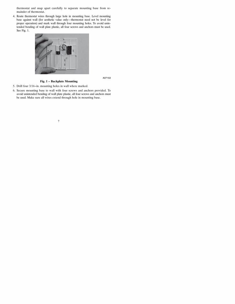
4. Route thermostat wires through large hole in mounting base. Level mountingbase against wall (for aesthetic value only—thermostat need not be level forproper operation) and mark wall through four mounting holes. To avoid unin-tended bending of wall plate plastic, all four screws and anchors must be used.See Fig. 1.
A07153Fig. 1 -- Backplate Mounting
5. Drill four 3/16--in. mounting holes in wall where marked.
6. Secure mounting base to wall with four screws and anchors provided. Toavoid unintended bending of wall plate plastic, all four screws and anchors mustbe used. Make sure all wires extend through hole in mounting base.
8
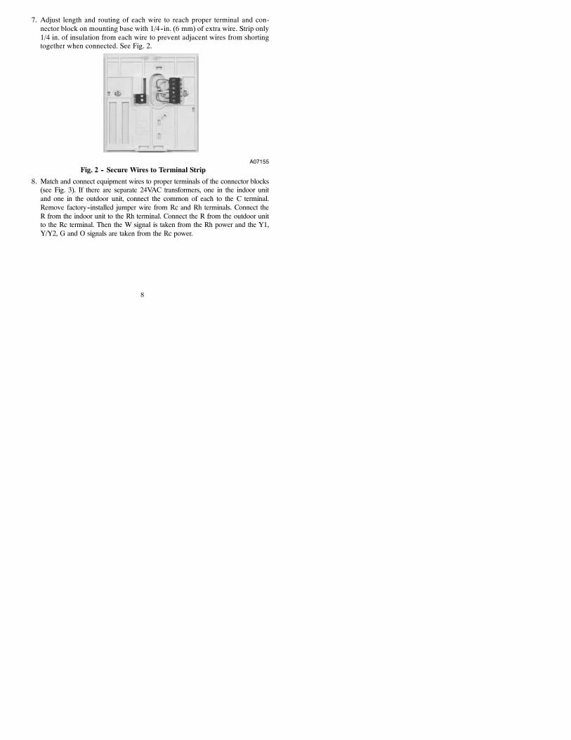
7. Adjust length and routing of each wire to reach proper terminal and con-nector block on mounting base with 1/4--in. (6 mm) of extra wire. Strip only1/4 in. of insulation from each wire to prevent adjacent wires from shortingtogether when connected. See Fig. 2.
A07155Fig. 2 -- Secure Wires to Terminal Strip
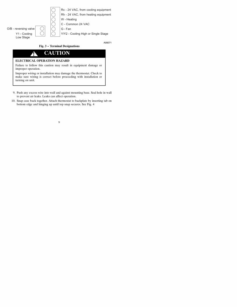
8. Match and connect equipment wires to proper terminals of the connector blocks(see Fig. 3). If there are separate 24VAC transformers, one in the indoor unitand one in the outdoor unit, connect the common of each to the C terminal.Remove factory--installed jumper wire from Rc and Rh terminals. Connect theR from the indoor unit to the Rh terminal. Connect the R from the outdoor unitto the Rc terminal. Then the W signal is taken from the Rh power and the Y1,Y/Y2, G and O signals are taken from the Rc power.
9
O/B - reversing valve
Y1 - CoolingLow Stage
Rc - 24 VAC, from cooling equipmentRh - 24 VAC, from heating equipmentW - HeatingC - Common 24 VACG - FanY/Y2 - Cooling High or Single Stage
A09271Fig. 3 -- Terminal Designations
ELECTRICAL OPERATION HAZARD
Failure to follow this caution may result in equipment damage orimproper operation.
Improper wiring or installation may damage the thermostat. Check tomake sure wiring is correct before proceeding with installation orturning on unit.
CAUTION!
9. Push any excess wire into wall and against mounting base. Seal hole in wallto prevent air leaks. Leaks can affect operation.
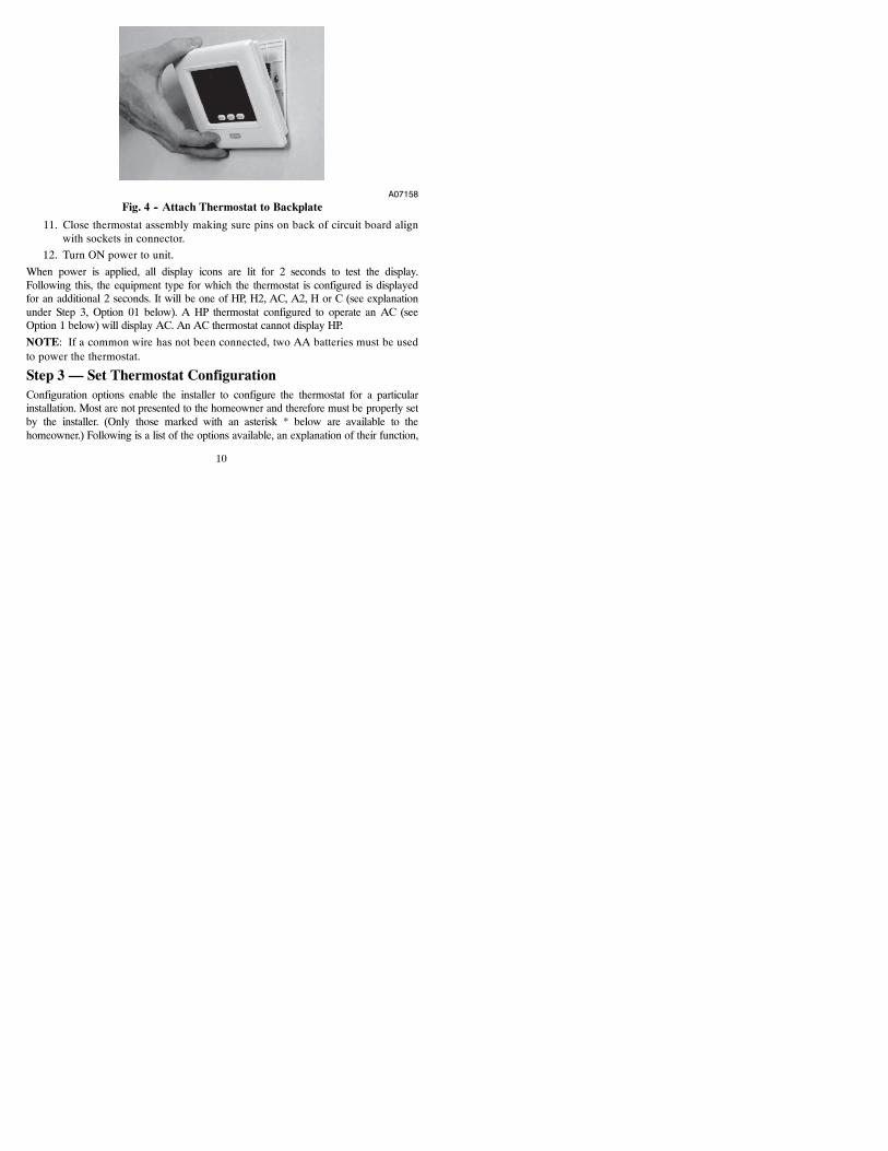
10. Snap case back together. Attach thermostat to backplate by inserting tab onbottom edge and hinging up until top snap secures. See Fig. 4
10
A07158Fig. 4 -- Attach Thermostat to Backplate
11. Close thermostat assembly making sure pins on back of circuit board alignwith sockets in connector.
12. Turn ON power to unit.
When power is applied, all display icons are lit for 2 seconds to test the display.Following this, the equipment type for which the thermostat is configured is displayedfor an additional 2 seconds. It will be one of HP, H2, AC, A2, H or C (see explanationunder Step 3, Option 01 below). A HP thermostat configured to operate an AC (seeOption 1 below) will display AC. An AC thermostat cannot display HP.
NOTE: If a common wire has not been connected, two AA batteries must be usedto power the thermostat.
Step 3 — Set Thermostat ConfigurationConfiguration options enable the installer to configure the thermostat for a particularinstallation. Most are not presented to the homeowner and therefore must be properly setby the installer. (Only those marked with an asterisk * below are available to thehomeowner.) Following is a list of the options available, an explanation of their function,
11
and their factory default settings. Not all numbers are used in the Legacy Series becausenot all options are available in this series -- and numbering is consistent across the T1,T2, and T6 thermostat lines.
Configuration Options -- Summary:Option 01 -- Equipment typeOption 03* -- Fahrenheit/CentigradeOption 04 -- Fan (G) on with W outputOption 07 -- ZoningOption 10 -- Reversing valveOption 11 -- Minimum deadband between heating and cooling setpointsOption 12 -- Smart Recovery (programmable models only)Option 13 -- Room air temperature offset adjustmentOption 15 -- Auto Changeover availabilityOption 16 -- Maximum cycles per hourOption 17 -- Time between equipment stagesOption 18* -- Continuous backlightingOption 21* -- Keypad lockoutOption 24* -- Programmable/non--programmable (programmable models only)Option 25* -- Number of programmable periods per dayOption 26 -- Minimum cooling setpointOption 27 -- Maximum heating setpointOption 99 -- Reset to factory defaultsThose options marked with an asterisk are also adjustable by the homeowner. SeeOwner’s Manual for further information.
12
To Enter the Configuration Mode:
Press and hold the FAN key for about 10 seconds until the display changes so thatonly two pairs of digits are showing. The left (programmable version) or the largeupper (non--programmable version) display shows the configuration number andthe right (programmable version) or small lower (non--programmable version)shows the configuration setting. Configuration number will be flashing whichmeans it can be adjusted using the UP and DOWN keys. To cause the opposite pairto flash (to be adjustable), press the MODE key. Successive presses of the MODEkey alternate between the configuration number and the configuration setting. Toexit the configuration mode, press the FAN key. If no key is pressed for 3 minutes,the configuration mode will automatically exit, returning the thermostat to normaloperation.
Configuration Options -- Selection:Option 01 -- Equipment type
Selections: with HP thermostat: HP, H2, AC, A2, H, C
with AC thermostat: AC, H, C
HP controls 1 speed heat pump with 1 stage of aux heat.
A2 controls two stages of cooling and one stage of furnace heat.
H2 controls a 2 Speed HP with 1 stage of aux heat.
AC controls 1 speed air conditioner with 1 stage of heat.
H operates a heat only system: furnace or fan coil only; no outdoor unit.
C operates a cool only system: outdoor AC unit with an indoor fan coil; no stripheater support.
Note that this option allows a HP thermostat to be converted to control an ACsystem.
13
Option 03 -- Fahrenheit/Centigrade
Selections:
F = Fahrenheit — Default is Fahrenheit.
C = Centigrade.
Selects temperature measurement units.
Option 04 -- Fan (G) ON with W output
Selections:
OF = G not energized with W — This is default.
ON = G energized with W.
This selection determines whether the fan (G) is to be ON or OFF when the W(furnace or strip heat) is ON. Furnaces and fan coils which manage their ownblowers do not require a separate G signal. Some auxiliary heaters require aseparate G signal to operate the blower when W is applied.
Option 07 -- Zoning
Selections:
OF = non--zoned system — This is default.
ON = zoned system.
ON disables thermostat’s internal timers which are not needed with zoning systemcontrols. Must be set to OF for non--zoned systems.
Option 10 -- Reversing valve
This selection is only available on heat pump systems. “O” terminal can beconfigured to be energized in either heating mode or in cooling mode, dependingon heat pump operation. “O” is used to describe a heat pump system that energizesits reversing valve in cooling. “B” is used to describe a heat pump system thatenergizes its reversing valve in heating.
14
H — Reversing valve output (O/W2/B) is energized when HEAT mode is selected.
C — Reversing valve output (O/W2/B) is energized when COOL mode is selected.
Default is C.
Option 11 -- Minimum Deadband Between Heating And Cooling
Selections:
01 through 06 — Default is 02.
Sets the minimum allowable number of degrees between heating and coolingsetpoints. One setpoint will “push” the other to maintain this difference.
Option 12 -- Smart Recovery (programmable model only)
Selections:
OF, 30, 60, 90 — Default is 90.
Smart Recovery OF means setpoints change immediately at a program schedulechange. Thirty, 60, or 90 selects the number of minutes recovery starts beforeprogrammed recovery time. Recovery takes place smoothly during the selectedrecovery time, ending at the recovery time and temperature which is programmed.If the setpoint is changed during smart recovery, the smart recovery is cancelled andthe new setpoint is effective immediately. Not available with non--programmablethermostats.
15
Option 13 -- Room Air Temperature Offset
Selections:
--5 to 5_ F — Default is 0.
This option selects the number of degrees F to be added to the displayedtemperature to calibrate or deliberately miscalibrate the measured roomtemperature.
Option 15 -- Auto Changeover Availability
Selections:
ON — This is default.
OF
ON allows automatic changeover between heating and cooling as demand requires.OF maintains either heating or cooling mode only. Auto changeover is not availablewhen H or C is selected under Option 1.
Option 16 -- Maximum Cycles Per Hour
Selections:
2, 4, or 6 — Default is 4.
The maximum cycle rate is limited by internal timers to the selected number ofcycles per hour. Selection of a higher number causes faster cycling resulting inmore constant room temperature.
Option 17 -- Minimum Time Between Equipment Stages
Selections:
10, 15, 20, 25 — Default is 15.
When there is an auxiliary stage of heat available, this is the amount of time theheat pump must operate before the aux stage can turn on. With heat pumps, longertimes can reduce the amount of auxiliary heat used. Not available with ACthermostats.
16
Option 18 -- Backlight Configuration
Selections:
ON, OF — Default is OF.
When ON is selected and the thermostat is not battery operated a low levelcontinuous display backlight is always on. With OF selected, the backlight is onlyon for a short time after the door is opened or a key is pressed. Continuousbacklight is not available with battery operation.
Option 21 -- Keypad Lockout
Selections:
ON, OF — Default is OF.
With OF selected, the keypad cannot be locked. With ON selected the keypad willbe locked and can be unlocked by simultaneously pressing the UP and DOWN keysfor 5 seconds. Once unlocked, it will relock 2 minutes after the last keypad press. A“lock” icon is displayed while it is locked.
Option 24 -- Programmable/Non--Programmable (programmable model only)
Selections:
P, nP — Default is P.
This option is only available on programmable models, allowing programming tobe disabled when nP is selected. The clock is displayed, but the program schedule,the HOLD and TEMPORARY HOLD functions are disabled.
Option 25 -- Number of Programmable Periods (programmable models only)
Selections:
2, 4 — Default is 4.
Selecting 2 allows 2 programming periods, P1 and P2, per day. Selecting 4 allowsperiods P1, P2 , P3, and P4. Not available with non--programmable thermostats.
17
Option 26 -- Minimum Cooling Setpoint
Selections:
52_F to 90_F — Default is 52_F.
Sets the lowest cooling setpoint available to the user.
Option 27 -- Maximum Heating Setpoint
Selections:
50_F to 88_F — Default is 88_F.
Sets the highest heating setpoint available to the user.
Option 99 -- Reset to Factory Defaults
Selection:
See below — There is no default.
Use this capability to reset the thermostat to “out of the box” conditions.
NOTE: All configuration settings, program settings, clock, and day which havebeen manually entered will be lost!
When this option is selected, the configuration number (99), will appear on the leftand 10 will appear on the right. To perform the reset, first use the MODE key tomake the 10 flash. Then press and hold the DOWN key. The 10 will start countingdown toward zero. If the DOWN key is kept pressed until the count reaches zero,the reset will be performed. If the DOWN key is released early, the number willreturn to 10 and the reset will not occur.
18
Step 4 — Check Thermostat OperationThe Legacy Series thermostats have a built--in installer test capability. Use it tocheck thermostat and equipment operation without delays or setpoint adjustmentsto force heating or cooling.
To enter the Installer Test mode, use the same process as is used to enter InstallerConfiguration, only hold the FAN key longer. More specifically, press and hold theFAN for about 15 seconds until the display reads In on the left and St on the rightfor the programmable model, or InS in the smaller display for thenon--programmable model. The MODE will be OFF. The MODE key (upper left)can now be used to select heat, cool, or emergency heat, if this is a HP thermostat.Selecting one of the available modes will immediately command the equipment toturn on in that mode. It will run for 3 minutes and then return the mode to off. WithHP thermostats (having 2 stages of heating), the test will run for 3 minutes on eachstage. If the thermostat is programmable, the clock display counts down from 180seconds while each stage operates. Changing the mode to OFF will terminate anyrunning test immediately.
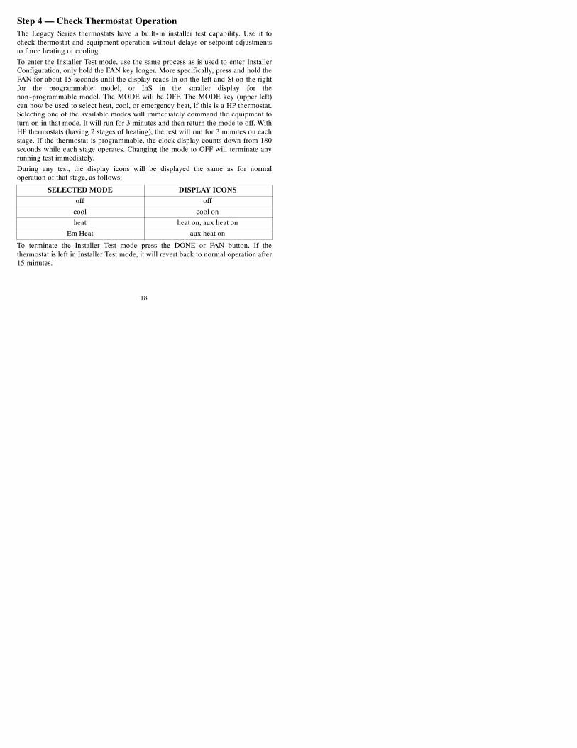
During any test, the display icons will be displayed the same as for normaloperation of that stage, as follows:
SELECTED MODE DISPLAY ICONS
off off
cool cool on
heat heat on, aux heat on
Em Heat aux heat on
To terminate the Installer Test mode press the DONE or FAN button. If thethermostat is left in Installer Test mode, it will revert back to normal operation after15 minutes.

19
Checklist
1. Run equipment through several heating and cooling cycles to ensure properoperation. To operate the thermostat in its normal operating mode, consultthe Owner’s Manual.
2. If the equipment is to be left in operation, the setpoints, operating mode,and possibly program schedule must be properly selected.
3. Put away tools and instruments and clean up debris.
4. Review and leave Owner’s Guide with owner.
20
FEATURES AND ACCESSORIESHome, Away, Sleep (programmable models only)This feature provides three button selections which select from three predeterminedpairs of heat and cool setpoints. In programmed versions, one of these three choicescan be selected for any programmed period. To change these settings, a temperatureis first selected and then the key pressed and held, similar to setting stations on apush--button radio. See Owner’s Manual for details.
Clock (programmable models only)Without batteries the clock will continue to operate for 8 hours while power isremoved. With batteries, the clock operates until the end of the battery life.
BatteriesBattery operation is available for installations where there is no common (C) wireavailable at the thermostat or where operation is to continue while the thermostat isremoved from the wall, usually to facilitate remote (armchair) programming. Forbattery operation, install two alkaline AA batteries. The thermostat is designed tooperate up to one year on a set of batteries. A battery indicator on the display warnswhen battery replacement is needed. See Homeowners Guide for details. If batteriesare installed and the thermostat is operated from 24VAC power, battery operationwill occur only when 24VAC power is not present. The changeover between24VAC power and battery power is automatic.
Display LightingThe display has two levels of lighting, high level and low level. High level lightingcomes on for 10 seconds when the door is opened and/or buttons are being pressedwith 24VAC and with batteries. Low level lighting is only available if thethermostat is operated from 24VAC. It is not available with batteries. The low levelcan be selected (see Option 18) for continuous backlight.

21
Door SwitchWhen the door is opened, the display changes from its normal operation view. Thelarge temperature display disappears so it will be available for other user functions. If thedoor is left open for 3 minutes, the display reverts to normal operation.
Mounting OptionsFor those installations requiring it, mounting hole locations for the programmablemodel are spaced to fit either a horizontal or vertical junction box. Mounting holelocations for the non--programmable are spaced to fit a horizontal junction box.
22
OPERATIONAL AND CONNECTION INFORMATIONRc/Rh ConnectionsFor installations having a separate 24VAC transformer for heating and cooling, theR connection can be separated into two connections, one for each transformer. Thisallows isolation between the two transformers to be preserved. To separate Rc fromRh, remove the factory supplied jumper between the Rc and Rh terminals. The Rhterminal powers the W output. The Rc terminal powers the Y1, Y/Y2, G and Ooutputs.
WiringFor all wiring applications, use 22 AWG or larger wire. Continuous wire lengthsover 100 ft. (30.5 m) should use 20 AWG or larger. Wire lengths are not to exceed250 ft. (76 m) per run.
O/B Terminal -- On HP Thermostat OnlyThis terminal is normally connected to the reversing valve of the heat pump. It iscalled O when the valve is energized in cooling and B when it is energized inheating. Option 10 of the Configuration Options makes the O/B selection.
TimersThere are several timers which influence the thermostat’s operation:
If any of the timers listed below is preventing the equipment from turning on, thedisplay icons which show the equipment is operating will be flashing to indicate aturn--on delay is present.
Five--Minute Compressor Timeguard
This timer prevents the compressor from starting unless it has been off for 5minutes. It can be defeated for one cycle by simultaneously pressing the FAN andUP keys.
23
Minimum On Timer
Once the equipment has been turned on, it must remain on for 3 minutes. A changein mode or setpoint will cancel this timer.
Cycle Timer
Based on the selection of 2, 4, or 6 cycles per hour, this timer is set to 30, 15, or 10minutes. This much time must elapse from the start of one cycle before anothercycle can start. It serves to impose the cycles per hour limits. It can be defeated forone cycle by simultaneously pressing the FAN and UP keys.
Auto Changeover Timer
To prevent unnecessary cycling between heating and cooling modes, this timerprevents a changeover to the opposite mode until a demand exists in the oppositemode for 20 minutes. It is defeated when setpoints are changed so that the oppositemode is immediately available if desired.
Error CodesTwo error messages indicate problems with the thermostat’s operation. If the roomtemperature sensor fails, the temperature display will show ----, two dashes. If thereis an internal memory failure, the temperature display will show E4. The remedy foreach of these is to replace the thermostat.
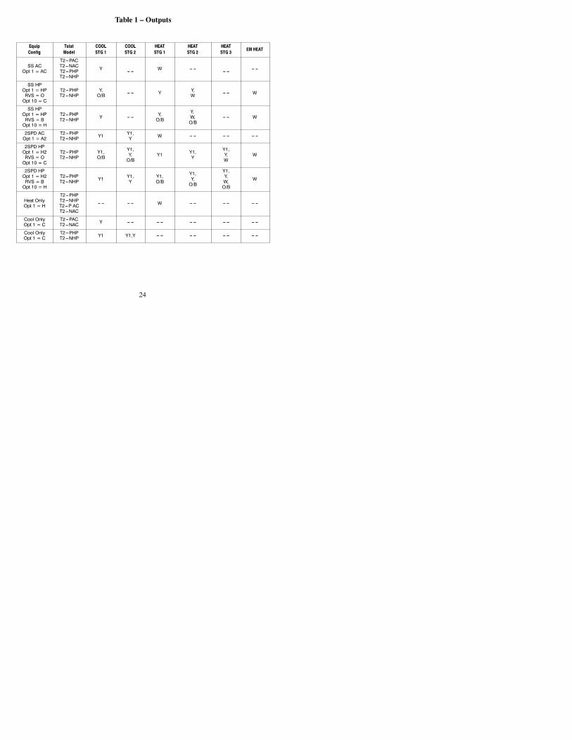
Table 1 shows the thermostat outputs for each available stage of heating or cooling.It may be useful in checkout or troubleshooting.
24
Table 1 – Outputs
EquipConfig
TstatModel
COOLSTG 1
COOLSTG 2
HEATSTG 1
HEATSTG 2
HEATSTG 3
EM HEAT
SS ACOpt 1 = AC
T2---PACT2---NACT2---PHPT2---NHP
Y --- --- W --- --- --- --- --- ---
SS HPOpt 1 = HPRVS = OOpt 10 = C
T2---PHPT2---NHP
Y,O/B --- --- Y Y,
W --- --- W
SS HPOpt 1 = HPRVS = BOpt 10 = H
T2---PHPT2---NHP Y --- --- Y,
O/B
Y,W,O/B
--- --- W
2SPD ACOpt 1 = A2
T2---PHPT2---NHP Y1 Y1,
Y W --- --- --- --- --- ---
2SPD HPOpt 1 = H2RVS = OOpt 10 = C
T2---PHPT2---NHP
Y1,O/B
Y1,Y,O/B
Y1 Y1,Y
Y1,Y,W
W
2SPD HPOpt 1 = H2RVS = BOpt 10 = H
T2---PHPT2---NHP Y1 Y1,
YY1,O/B
Y1,Y,O/B
Y1,Y,W,O/B
W
Heat OnlyOpt 1 = H
T2---PHPT2---NHPT2---P ACT2---NAC
--- --- --- --- W --- --- --- --- --- ---
Cool OnlyOpt 1 = C
T2---PACT2---NAC Y --- --- --- --- --- --- --- --- --- ---
Cool OnlyOpt 1 = C
T2---PHPT2---NHP Y1 Y1,Y --- --- --- --- --- --- --- ---
25
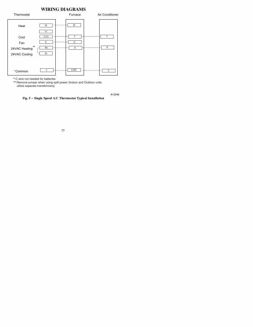
WIRING DIAGRAMS
*
* C wire not needed for batteries** Remove jumper when using split power (Indoor and Outdoor units utilize separate transformers).
Y1
Y/Y2
W
G
Rh
Rc
C C
G
R R
W
Y
COM
Y
**
A12246Fig. 5 -- Single Speed A/C Thermostat Typical Installation
26
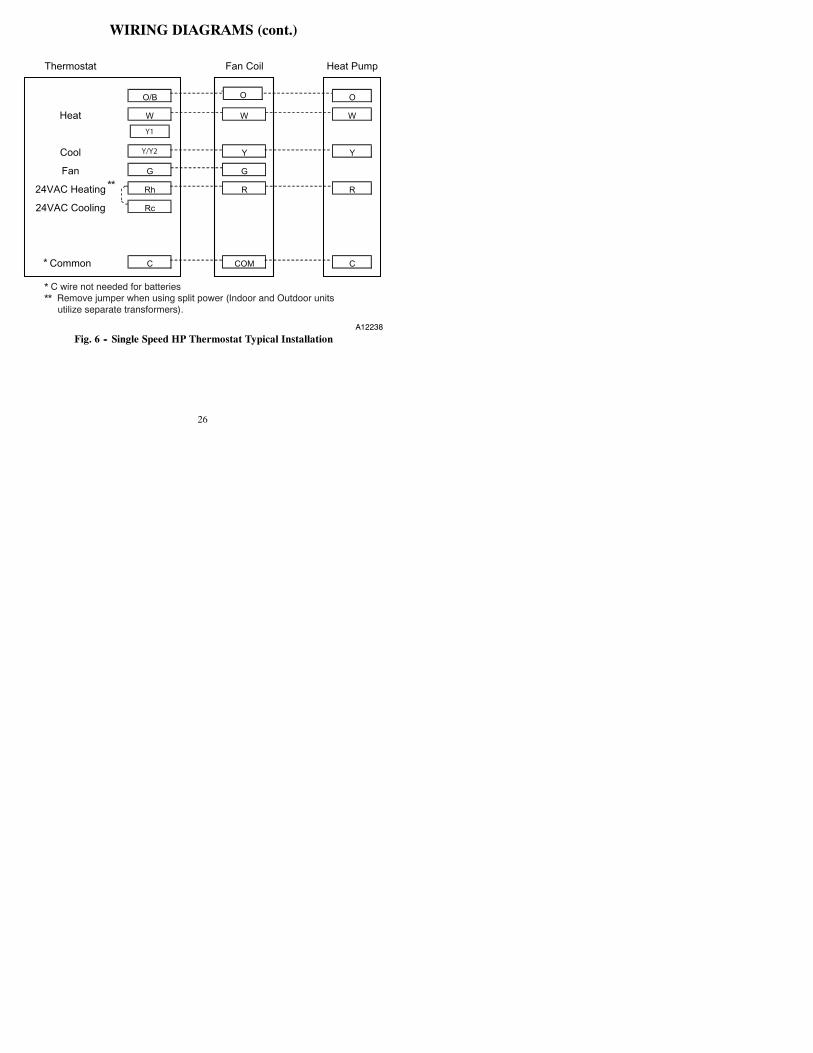
WIRING DIAGRAMS (cont.)
*
* C wire not needed for batteries** Remove jumper when using split power (Indoor and Outdoor units utilize separate transformers).
Y1
Y/Y2
**
A12238
Fig. 6 -- Single Speed HP Thermostat Typical Installation
27
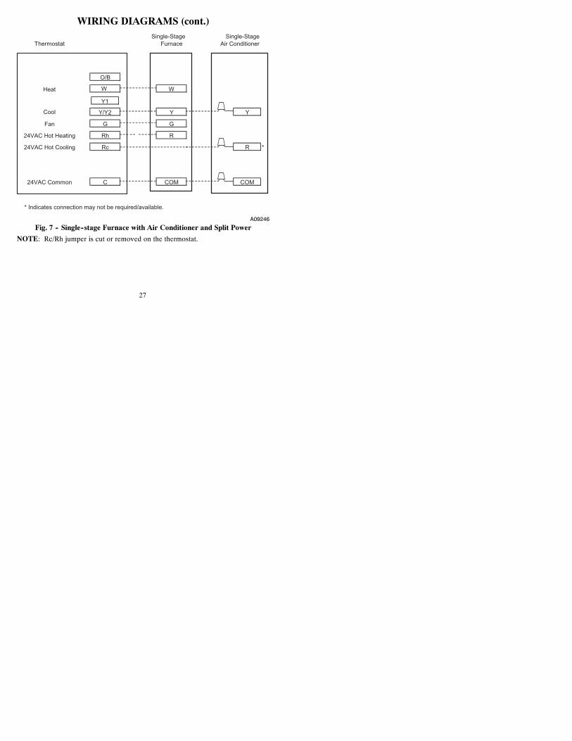
WIRING DIAGRAMS (cont.)Single-Stage Single-Stage
Thermostat Furnace Air Conditioner
O/B
Heat W W
Y/Y2 Y Y
Fan G G
24VAC Hot Heating Rh R
24VAC Hot Cooling Rc R *
24VAC Common C COM COM
Cool
* Indicates connection may not be required/available.
Y1
A09246
Fig. 7 -- Single--stage Furnace with Air Conditioner and Split Power
NOTE: Rc/Rh jumper is cut or removed on the thermostat.
28
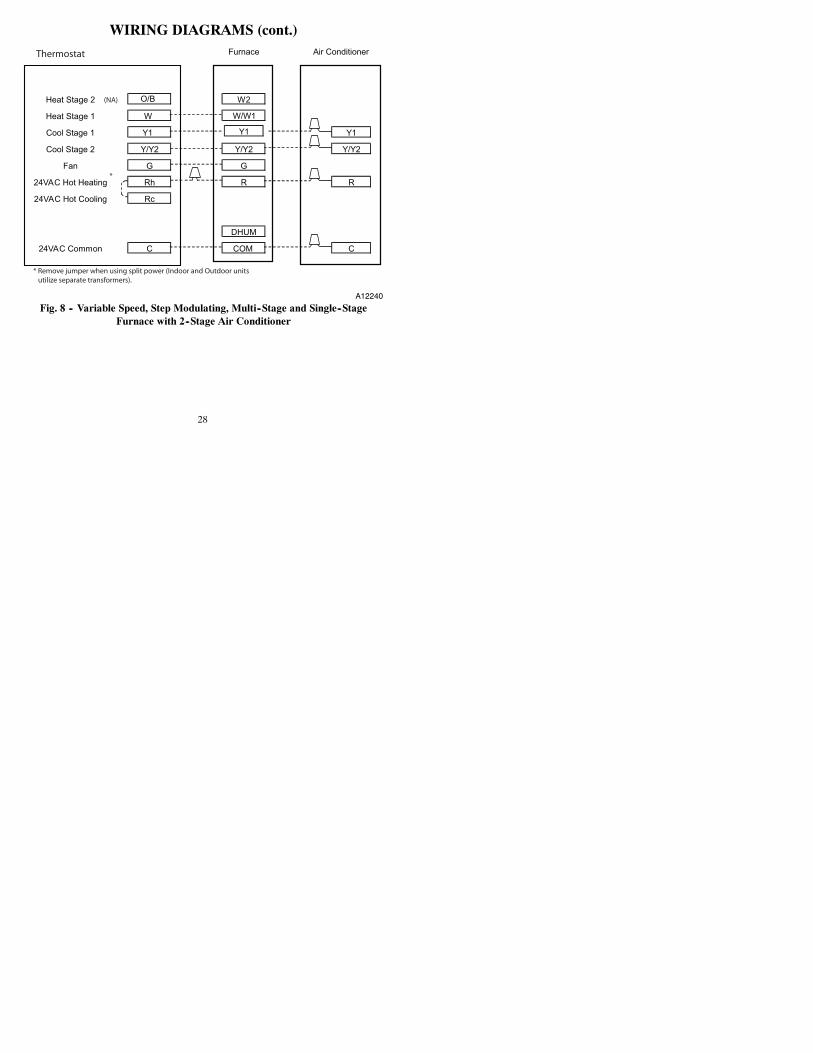
WIRING DIAGRAMS (cont.)Furnace Air Conditioner
Heat Stage 2 O/B W2
Heat Stage 1 W W/W1
Cool Stage 1 Y1 Y1
Cool Stage 2 Y/Y2 Y/Y2 Y/Y2
Fan G G
24VAC Hot Heating Rh R R
24VAC Hot Cooling Rc
DHUM
24VAC Common C COM C
Y1
Thermostat
(NA)
*
* Remove jumper when using split power (Indoor and Outdoor units
utilize separate transformers).
A12240
Fig. 8 -- Variable Speed, Step Modulating, Multi--Stage and Single--StageFurnace with 2--Stage Air Conditioner
29
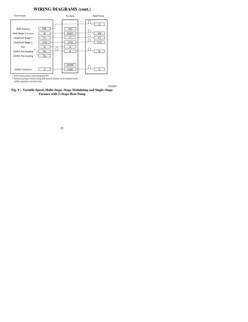
WIRING DIAGRAMS (cont.)Furnace Heat Pump
O
RVS Cooling O/B W2
Heat Stage 3 (furnace) W W/W1 W2*
Heat/Cool Stage 1 Y1 Y1
Heat/Cool Stage 2 Y/Y2 Y/Y2 Y/Y2
Fan G G
24VAC Hot Heating Rh R R
24VAC Hot Cooling Rc
DHUM
24VAC Common C COM C
Y1
**
* Some heat pumps may designate W1.
**Remove jumper when using split power (Indoor and Outdoor Units
utilize separate transformers).
Thermostat
A12241
Fig. 9 -- Variable Speed, Multi--Stage, Stage Modulating and Single--StageFurnace with 2--Stage Heat Pump
30
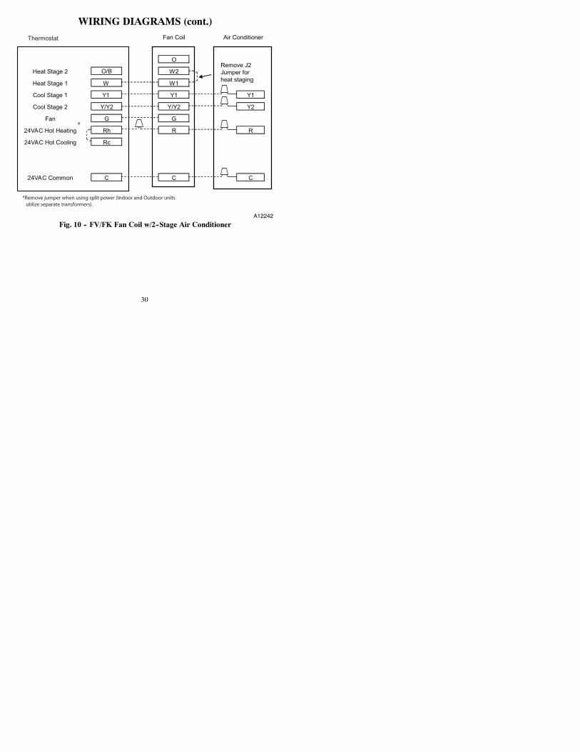
WIRING DIAGRAMS (cont.)Fan Coil Air Conditioner
ORemove J2Jumper forheat staging
Heat Stage 2 O/B W2
Heat Stage 1 W W1
Cool Stage 1 Y1 Y1 Y1
Cool Stage 2 Y/Y2 Y/Y2 Y2
Fan G G
24VAC Hot Heating Rh R R
24VAC Hot Cooling Rc
24VAC Common C C C
Thermostat
*
*Remove jumper when using split power (Indoor and Outdoor units
utilize separate transformers).
A12242
Fig. 10 -- FV/FK Fan Coil w/2--Stage Air Conditioner
31
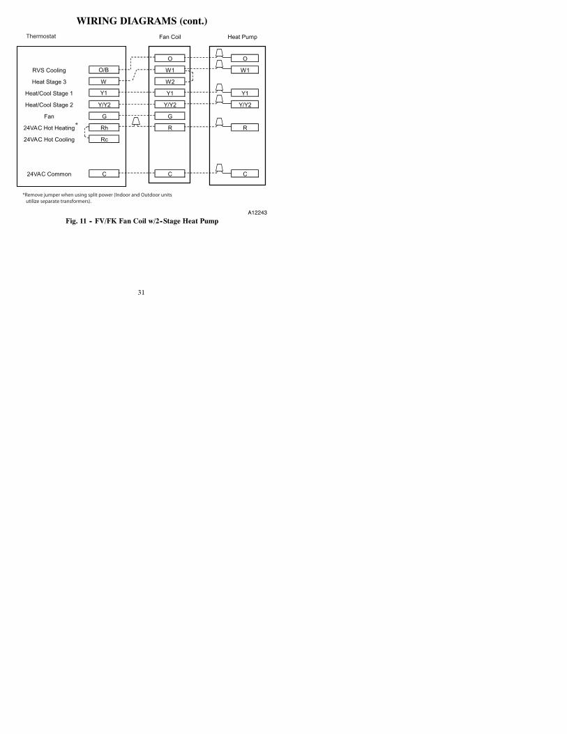
WIRING DIAGRAMS (cont.)Fan Coil Heat Pump
O O
RVS Cooling O/B W1 W1
Heat Stage 3 W W2
Heat/Cool Stage 1 Y1 Y1 Y1
Heat/Cool Stage 2 Y/Y2 Y/Y2 Y/Y2
Fan G G
24VAC Hot Heating Rh R R
24VAC Hot Cooling Rc
24VAC Common C C C
Thermostat
*Remove jumper when using split power (Indoor and Outdoor units
utilize separate transformers).
*
A12243
Fig. 11 -- FV/FK Fan Coil w/2--Stage Heat Pump
32
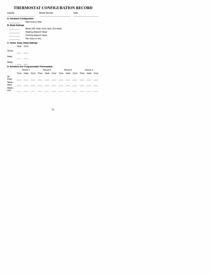
THERMOSTAT CONFIGURATION RECORDInstaller_________________________
Model Number_____________________________
Date_______________________
A. Hardware Configuration__________ Seal Hole In Wall
B. Mode Settings__________ Mode (Off, Heat, Cool, Auto, Em Heat)
__________ Heating Setpoint Value
__________ Cooling Setpoint Value
__________ Fan (Auto or On)
C. Home, Away, Sleep SettingsHeat Cool
Home ____ ____
Away ____ ____
Sleep ____ ____D. Schedule (For Programmable Thermostats)
Period 1 Period 2 Period 3 Period 4
Time Heat Cool Time Heat Cool Time Heat Cool Time Heat Cool
AllDays ____ ____ ____ ____ ____ ____ ____ ____ ____ ____ ____ ____Week---days ____ ____ ____ ____ ____ ____ ____ ____ ____ ____ ____ ____Week---end ____ ____ ____ ____ ____ ____ ____ ____ ____ ____ ____ ____
33
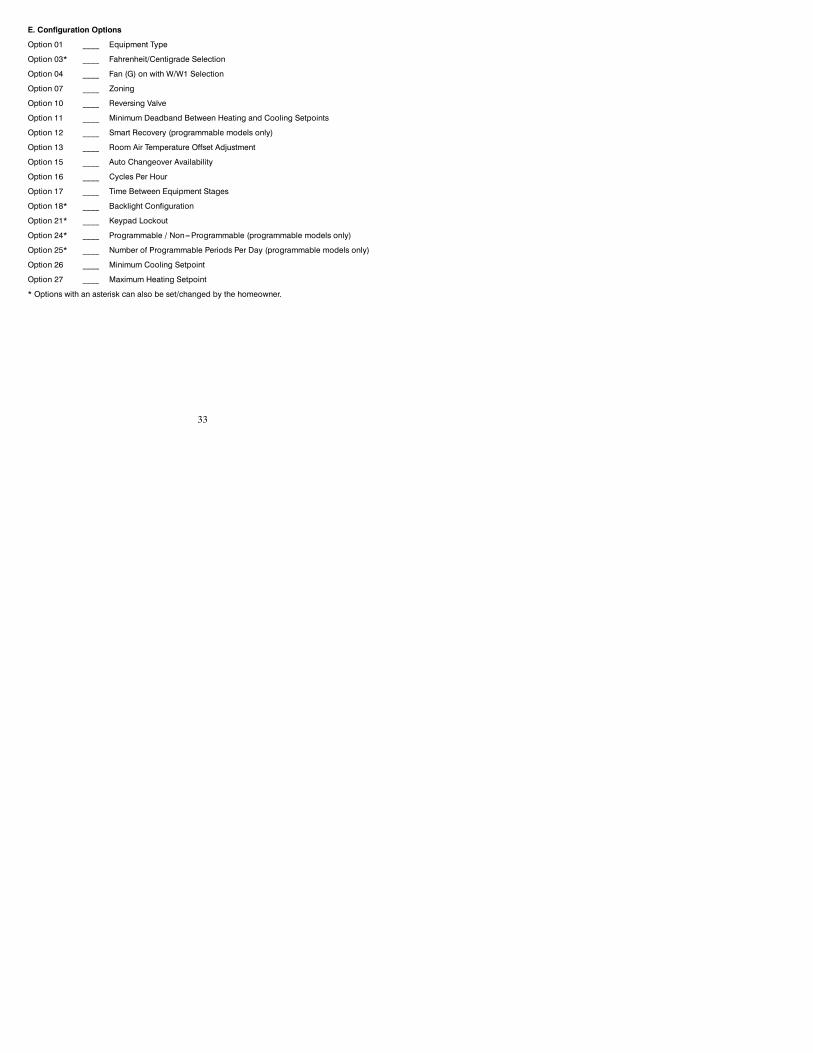
E. Configuration Options
Option 01 ____ Equipment Type
Option 03* ____ Fahrenheit/Centigrade Selection
Option 04 ____ Fan (G) on with W/W1 Selection
Option 07 ____ Zoning
Option 10 ____ Reversing Valve
Option 11 ____ Minimum Deadband Between Heating and Cooling Setpoints
Option 12 ____ Smart Recovery (programmable models only)
Option 13 ____ Room Air Temperature Offset Adjustment
Option 15 ____ Auto Changeover Availability
Option 16 ____ Cycles Per Hour
Option 17 ____ Time Between Equipment Stages
Option 18* ____ Backlight Configuration
Option 21* ____ Keypad Lockout
Option 24* ____ Programmable / Non---Programmable (programmable models only)
Option 25* ____ Number of Programmable Periods Per Day (programmable models only)
Option 26 ____ Minimum Cooling Setpoint
Option 27 ____ Maximum Heating Setpoint
* Options with an asterisk can also be set/changed by the homeowner.

34

35

36

Copyright 2012 Bryant Corporation 7310 W Morris St. Indianapolis, IN 46231
IIT2---PAC---06 Replaces: IIT2---PAC---05
Edition Date: 07/12
Manufacturer reserves the right to change, at any time, specifications and designs without notice
and without obligations.