T1 Weight transmitter ETHERNET TCP/IP - Zemic Europe · Installation and User Manual version 2.0 T1...
51
Installation and User Manual version 2.0 T1 Weight transmitter ETHERNET TCP/IP 2004/108/EC EN55022 EN61000-6-2 EN61000-6-4 SYSTEM IDENTIFICATION Top Sensors products are sold by: Zemic Europe B.V. Tel: +31 765039480 Leerlooierstraat 8 Fax: +31 765039481 4871 EN Etten-Leur [email protected] A Zemic Europe brand ® The Netherlands www.top-sensors.com
Transcript of T1 Weight transmitter ETHERNET TCP/IP - Zemic Europe · Installation and User Manual version 2.0 T1...

Installation and User Manual version 2.0
T1 Weight transmitter
ETHERNET TCP/IP
2004/108/EC
EN55022 EN61000-6-2 EN61000-6-4 SYSTEM IDENTIFICATION
Top Sensors products are sold by: Zemic Europe B.V. Tel: +31 765039480 Leerlooierstraat 8 Fax: +31 765039481 4871 EN Etten-Leur [email protected] A Zemic Europe brand ® The Netherlands www.top-sensors.com

KEY TO SYMBOLS
Below are the symbols used in the manual to draw the reader's
Attention: Caution! High Voltage.
Caution! This operation must be performed by skilled workers.
Read the following indications carefully.
Further information.
GUARANTEE
12 months from the delivery document date. The guarantee covers only defected parts and includes the replacement parts and labour. All shipping and packing costs are paid by the customer. It is possible to have the repair in guarantee on condition that the returned product has not been transformed, damaged or repaired without authorization. No guarantee is applicable on returned products without the original label and/or serial number. No guarantee against misuse Disposal of Waste Equipment by Users in Private Households in the European Union
This symbol on the product or on its packaging indicates that this product must not be disposed of with your other household waste. Instead, it is your responsibility to dispose of your waste equipment by handing it over to a designated collection point for the recycling of waste electrical and electronic equipment. The separate collection and recycling of your waste equipment at the time of disposal will help preserve natural resources and protect human health and the environment. For more information about where you can drop off your waste equipment for recycling, please contact your local waste disposal Authority or the equipment retailer.

TABLE OF CONTENTS
1. USER WARNINGS 1. RECOMMENDATIONS FOR CORRECT INSTALLATION OF WEIGHING INSTRUMENTS 1. RECOMMENDATIONS FOR CORRECT INSTALLATION OF THE LOAD CELLS
3. LOAD CELL INPUT TEST (QUICK ACCESS) 3. LOAD CELL TESTING
4. MAIN SPECIFICATIONS OF THE INSTRUMENT 5. TECHNICAL SPECIFICATIONS 6. ELECTRICAL CONNECTIONS
6. BASIC INFORMATION 6. WIRING DIAGRAM
7. LED AND KEY FUNCTIONS 8. MENU MAP
8. SETPOINT 8. SYSTEM PARAMETERS
9. INSTRUMENT COMMISSIONING 10. PROGRAMMING OF SYSTEM PARAMETERS
10. THEORETICAL CALIBRATION 11. MAXIMUM CAPACITY 11. TARE WEIGHT ZERO SETTING 11. ZERO VALUE MANUAL ENTRY
12. REAL CALIBRATION (WITH SAMPLE WEIGHTS) 13. FILTER ON THE WEIGHT 14. ZERO PARAMETERS
14. RESETTABLE WEIGHT SETTING FOR SMALL WEIGHT CHANGES 14. AUTOMATIC ZERO SETTING AT POWER-ON 14. ZERO TRACKING
15. ETHERNET TCP/IP SETTING 15. SETTING UNITS OF MEASURE
16. DISPLAY COEFFICIENT
17. OUTPUTS AND INPUTS CONFIGURATION 18. SEMI-AUTOMATIC TARE (NET/GROSS) 19. PRESET TARE (SUBTRACTIVE TARE DEVICE) 20. SEMI-AUTOMATIC ZERO (WEIGHT ZERO-SETTING FOR SMALL VARIATIONS) 20. PEAK 20. SERIAL COMMUNICATION SETTINGS
22. RS485 SERIAL COMMUNICATION 22. DIRECT CONNECTION BETWEEN RS485 AND RS232 WITHOUT CONVERTER
23. TEST 23.SETPOINTS PROGRAMMING

24.ALARMS 25. ETHERNET CONNECTION TO PC
26. DIAGNOSTIC 27. WEBSITE
29.FAST CONTINUOUS TRANSMISSION PROTOCOL 30.CONTINUOUS TRANSMISSION PROTOCOL TO REMOTE DISPLAYS 31.ASCII BIDIRECTIONAL PROTOCOL 37.MODBUS-RTU PROTOCOL 45.RESERVED FOR THE INSTALLER
45.MENU LOCKING 45.MENU UNLOCKING 45.TEMPORARY MENU UNLOCKING 45.PROGRAM SELECTION AND DATA DELETION 46.KEYPAD OR DISPLAY LOCKING
47.DECLARATION OF CONFORMITY

1
USER WARNINGS
RECOMMENDATIONS FOR THE PROPER USE OF WEIGHING INSTRUMENT - Keep away from heat sources and direct sunlight - Protect the instrument from rain (except special IP versions) - Do not wash with water jets (except special IP versions) - Do not dip in water - Do not spill liquid on the instrument - Do not use solvents to clean the instrument - Do not install in areas subject to explosion hazard (except special Atex versions)
RECOMMENDATIONS FOR CORRECT INSTALLATION OF WEIGHING INSTRUMENTS
The terminals indicated on the instrument’s wiring diagram to be connected to earth must have the same potential as the weighed structure (same earthing pit or earthing system). If you are unable to ensure this condition, connect with an earthing wire the terminals of the instrument (including the terminal 0VDC) to the weighed structure. The cell cable must be individually led to its panel input and not share a conduit with other cables; connect it directly to the instrument terminal strip without breaking its route with support terminal strips. Use “RC” filters on the instrument-driven solenoid valve and remote control switch coils. Avoid inverters in the instrument panel; if inevitable, use special filters for the inverters and separate them with sheet metal partitions. The panel installer must provide electric protections for the instruments (fuses, door lock switch etc.). It is advisable to leave the equipment always switched on to prevent the formation of condensation.
MAXIMUM CABLE LENGTHS - RS485: 1000 meters with AWG24, shielded and twisted cables - RS232: 15 meters for baud rates up to 19200
RECOMMENDATIONS FOR CORRECT INSTALLATION OF THE LOAD CELLS
INSTALLING LOAD CELLS: The load cells must be placed on rigid, stable in-line structures; it is important to use the mounting modules for load cells to compensate for misalignment of the support surfaces.
PROTECTION OF THE LOAD CELL CABLE: Use water-proof sheaths and joints in order to protect the cables of the load cells.
MECHANICAL RESTRAINTS (pipes, etc.): When pipes are present, we recommend the use of hoses and flexible couplings with open mouthpieces with rubber protection; in case of hard pipes, place the pipe support or anchor bracket as far as possible from the weighed structure (at a distance at least 40 times the diameter of the pipe).

2
CONNECTING SEVERAL LOAD CELLS IN PARALLEL: Connect several l o a d cells in parallel by using - if necessary - a watertight junction box with terminal box. The load cell connection extension cables must be shielded, led individually into their piping or conduit and laid as far as possible from the power cables (in case of 4-wire connections, use cables with 4 x 1 sq.mm minimum cross-section).
WELDING: Avoid welding with the load cells already installed. If this cannot be avoided, place the welder ground clamp close to the required welding point to prevent sending current through the load cell body.
WINDY CONDITIONS - KNOCKS - VIBRATIONS: The use of weigh modules is strongly recommended for all load cells to compensate for misalignment of the support surfaces. The system designer must ensure that the plant is protected against lateral shifting and tipping relating to: shocks and vibration; windy conditions; seismic conditions in the installation setting; stability of the support structure.
EARTHING THE WEIGHED STRUCTURE: By means of a copper wire with suitable cross-section, connect the load cell upper support plate with the lower support plate, then connect all the lower plates to a single earthing system. Electrostatic charges accumulated because of the product rubbing against the pipes and the weighed container walls are discharged to the ground without going through or damaging the load cells. Failure to implement a proper earthing system might not affect the operation of the weighing system; this, however, does not rule out the possibility that the load cells and connected instrument may become damaged in the future. It is forbidden to ensure earthing system continuity by using metal parts contained in the weighed structure.
FAILURE TO FOLLOW THE INSTALLATION RECOMMENDATIONS WILL BE CONSIDERED A MISUSE OF THE EQUIPMENT

3
LOAD CELL INPUT TEST (QUICK ACCESS) From the weight display, press for 3 seconds; the response signal of the load cells is displayed, expressed in mV with four decimals.
LOAD CELL TESTING
Load cell resistance measurement (use a digital multimeter):
- Disconnect the load cells from the instrument and check that there is no moisture in the cell junction box caused by condensation or water infiltration. If so, drain the system or replace it if necessary.
- The value between the positive signal wire and the negative signal wire must be equal or similar to the one indicated in the load cell data sheet (output resistance).
- The value between the positive excitation wire and the negative excitation wire must be equal or similar to the one indicated in the load cell data sheet (input resistance).
- The insulation value between the shield and any other cell wire and between any other cell wire and the body of the load cell must be higher than 20 Mohm (mega ohms).
Load cell voltage measurement (use a digital multimeter):
- Take out the load cell to be tested from underneath the container, or alternatively, lift the container support.
- Make sure that the excitation of two wires of the load cell connected to the instrument (or amplifier) is 5 Vdc +/- 3%.
- Measure the response signal between the positive and the negative signal wires by directly connecting them to the tester, and make sure that it is comprised between 0 and 0.5 mV.
- Apply load to the load cell and make sure that there is a signal increment.
IF ONE OF THE ABOVE CONDITIONS IS NOT MET, PLEASE CONTACT THE TECHNICAL ASSISTANCE SERVICE.

4
MAIN SPECIFICATIONS OF THE INSTRUMENT
- Weight indicator and transmitter for Omega/DIN rail mounting suitable for back panel; space-
saving vertical shape. Six-digit semialphanumeric display (18mm h), 7 segment. Four-key keyboard. Dimensions: 25x115x120 mm.
- Displays the gross weight; from external contact allows to zero set or display the net weight (both values will be lost when the instrument is turned off).
- Peak weight function. - Ethernet TCP/IP port. - Transmits the gross or net weight via RS485 serial port, by means of protocols:
▫ Modbus RTU ▫ ASCII bidirectional protocol ▫ Continuous transmission

5
TECHNICAL SPECIFICATIONS
POWER SUPPLY and CONSUMPTION (VDC) 12 - 24 VDC +/- 10% ; 5 W
NO. OF LOAD CELLS IN PARALLEL and SUPPLY max 8 ( 350 ohm ) ; 5VDC/120mA
LINEARITY < 0.01% F.S. THERMAL DRIFT < 0.0005 % F.S. /°C A/D CONVERTER 24 bit (16.000.000 points) MAX DIVISIONS (with measurement range: +/-10mV = sens. 2mV/V)
+/- 999999
MEASUREMENT RANGE +/- 39 mV
MAX SENSITIVITY OF USABLE LOAD CELLS +/-7mV/V
MAX CONVERSIONS PER SECOND 300 conversions/second
DISPLAY RANGE - 999999 ; + 999999
NO. OF DECIMALS / DISPLAY INCREMENTS 0 - 4 / x 1 x 2 x 5 x 10 x 20 x 50 x 100
DIGITAL FILTER / READINGS PER SECOND 0.012 – 7 sec / 5 - 300 Hz
RELAY LOGIC OUTPUTS N.3 - max 115 VAC ; 150mA
LOGIC INPUTS N.2 - optoisolated 5 - 24 VDC PNP
SERIAL PORTS RS485
BAUD RATE 2400, 4800, 9600, 19200, 38400, 115200
HUMIDITY (non condensing) 85 %
STORAGE TEMPERATURE - 30°C + 80°C
WORKING TEMPERATURE - 20°C + 60°C ETHERNET TCP/IP PORT RJ45 10Base-T or 100Base-TX (auto detect)

6
ELECTRICAL CONNECTIONS
BASIC INFORMATIONS
- It is recommended that the power supply negative pole be grounded. - It is possible to supply up to eight 350 ohm load cells or sixteen 700 ohm load cells. - For 4-wire load cells, make a jumper between EX- and REF- and between EX+ and REF+. - Connect terminal “0 VDC” to the RS485 common of the connected instruments in the event that
these receive alternating current input or that they have an optoisolated RS485. - In case of an RS485 network with several devices it is recommended to activate the 120 ohm
termination resistance on the two devices located at the ends of the network, as described in the paragraph RS485 SERIAL CONNECTION.
WIRING DIAGRAM
3 outputs: settable setpoints or remote output management via protocol. 2 inputs (Default: SEMI-AUTOMATIC ZERO input 1; NET/GROSS input 2): settable to have the following functions: SEMI-AUTOMATIC ZERO, NET/GROSS, PEAK or REMOTE CONTROL (see paragraph OUTPUTS AND INPUTS CONFIGURATION)
7
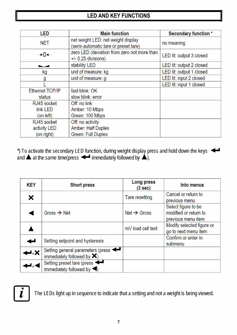
LED AND KEY FUNCTIONS
*) To activate the secondary LED function, during weight display press and hold down the keys and at the same time(press immediately followed by ).
The LEDs light up in sequence to indicate that a setting and not a weight is being viewed.

8
MENU MAP
Within the menu, the changes are applied immediately after pressing the button (no further confirmation).
SETPOINT
SYSTEM PARAMETERS

9
INSTRUMENT COMMISSIONING
Upon switch-on, the display shows in sequence: - (ONLY in case of approved program); - instrument model (e.g.: “ ”); - “ ” followed by the software code (e.g.: ); - program type: (base); - “ ” followed by the software version (e.g.: ); - “ ” followed by the hardware code (e.g.: ); - the serial number (e.g.: );
Check that the display shows the weight and that when loading the load cells there is an increase in weight. If there is not check and verify the connections and correct positioning of the load cells.
- If the instrument has already been theoretical CALIBRATED (plant system identification tag present on the instrument and on the cover: load cell’s rated data already entered): ▫ Reset to zero (follow the procedure in paragraph TARE WEIGHT ZERO SETTING) ▫ Check the calibration with sample weights and correct the indicated weight if necessary
(follow the procedure in paragraph REAL CALIBRATION (WITH SAMPLE WEIGHTS)).
- If the instrument HAS NOT BEEN CALIBRATED (missing plant system identification tag) proceed with calibration: ▫ If load cells data are unknown, follow the procedure in paragraph REAL CALIBRATION
(WITH SAMPLE WEIGHTS) ▫ Enter the rated data of load cells following the procedure given in paragraph THEORETICAL
CALIBRATION ▫ Reset to zero (follow the procedure in paragraph TARE WEIGHT ZERO SETTING) ▫ Check the calibration with sample weights and correct the indicated weight if necessary
(follow the procedure in paragraph REAL CALIBRATION (WITH SAMPLE WEIGHTS)).
- If Ethernet TCP/IP is used, set the related parameters (see section ETHERNET TCP/IP SETTINGS).
- If you use serial communication, set the related parameters (see section SERIAL COMMUNICATION SETTING).
- If setpoints are used, set the required weight values and the relevant parameters (see sections SETPOINTS PROGRAMMING and OUTPUTS AND INPUTS CONFIGURATION).

10
PROGRAMMING OF SYSTEM PARAMETERS
From the weight display, press simultaneously keys and to access the parameter setting. : to enter a menu/confirm the data entry.
: to modify the displayed value or menu item. : to select a new value or modify the displayed menu item. : to cancel and return to the previous menu.
THEORETICAL CALIBRATION
This function allows the load cell rated values to be set.
To perform the theoretical calibration set the following parameters in sequence: - (Default: ): The system full scale is given by one cell capacity multiplied by the
number of cells used. Example of system full scale value calculation: 4 cells of 1000kg FULL SCALE = 1000 X 4 = 4000. The instrument is supplied with a theoretical full scale value corresponding to 10000. To restore factory values, set 0 as full scale.
- (Default: 2.00000 mV/V): Sensitivity is a load cell rated parameter expressed in mV/V. Set the average sensitivity value indicated on the load cells. It’s possible to set a value between 0.50000 and 7.00000 mV/V. Example of 4-cell system with sensitivity: 2.00100, 2.00150, 2.00200, 2.00250; enter 2.00175, calculated as (2.00100 + 2.00150 + 2.00200 + 2.00250) / 4.
- : The division (resolution) is the minimum weight increment value which can be displayed. It is automatically calculated by the system according to the performed calibration, so that it is equal to 1/10000 of full scale. It can be changed and be variable between 0.0001 and 100 with x1 x2 x5 x10 increments.
- By modifying the theoretical full scale, the sensitivity or divisions, the real calibration is cancelled and the theoretical calibration only is considered valid.
- If the theoretical full scale and the recalculated full scale in real calibration (see paragraph REAL CALIBRATION (WITH SAMPLE WEIGHTS)) are equal, this means that the calibration currently in use is theoretical; if they are different, the calibration in use is the real calibration based on sample weights.
- By modifying the theoretical full scale, the sensitivity or divisions and all the system’s parameters containing a weight value will be set to default values (setpoint, hysteresis, etc.).

11
MAXIMUM CAPACITY
: Maximum displayable weight (from 0 to max full scale; default: 0). When the weight exceeds this value by 9 divisions the following is displayed ‘ˉˉˉˉˉˉ’. To disable this function, set 0.
TARE WEIGHT ZERO SETTING
This menu may also be accessed directly from the weight display, holding down the key for 3 seconds.
Perform this procedure after having set the THEORETICAL CALIBRATION data.
Use this function to set to zero the weight of the empty system after commissioning and then later on to compensate zero variations due to the presence of product residues. Procedure: - Confirm the message (Zero) by pressing. - The weight value to be set to zero is displayed. In this phase all of the LEDs are flashing. - Confirming once again, the weight is set to zero (the value is stored to the permanent memory). - Press to display the value of the total weight reset by the instrument, given by the sum of all of
the previous zero settings.
ZERO VALUE MANUAL ENTRY
WARNING: Perform this procedure only if it’s not possible to reset the weighed structure tare, for example because it contains product that can not be unloaded.
Set in this parameter the estimated zero value (from 0 to max 999999; default: 0).
12
REAL CALIBRATION (WITH SAMPLE WEIGHTS)
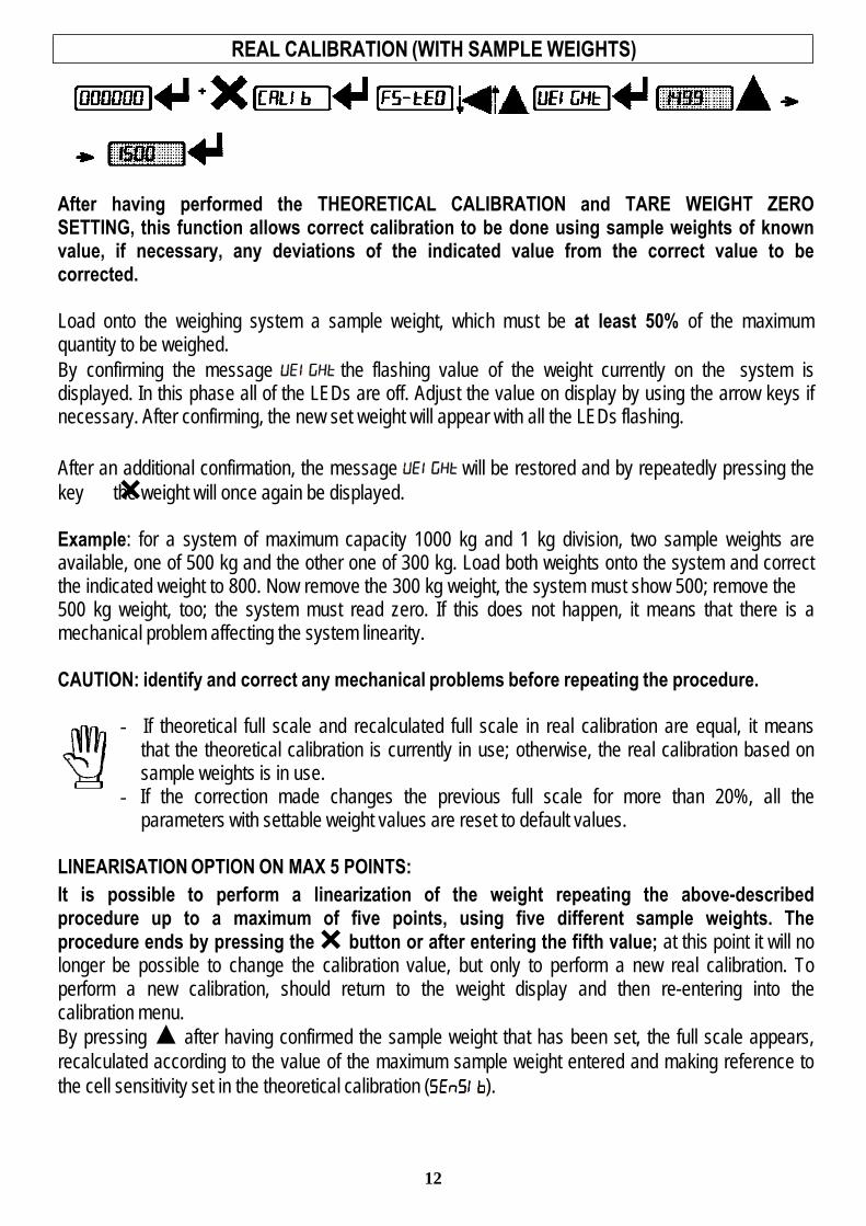
After having performed the THEORETICAL CALIBRATION and TARE WEIGHT ZERO SETTING, this function allows correct calibration to be done using sample weights of known value, if necessary, any deviations of the indicated value from the correct value to be corrected.
Load onto the weighing system a sample weight, which must be at least 50% of the maximum quantity to be weighed. By confirming the message the flashing value of the weight currently on the system is displayed. In this phase all of the LEDs are off. Adjust the value on display by using the arrow keys if necessary. After confirming, the new set weight will appear with all the LEDs flashing. After an additional confirmation, the message will be restored and by repeatedly pressing the key the weight will once again be displayed.
Example: for a system of maximum capacity 1000 kg and 1 kg division, two sample weights are available, one of 500 kg and the other one of 300 kg. Load both weights onto the system and correct the indicated weight to 800. Now remove the 300 kg weight, the system must show 500; remove the 500 kg weight, too; the system must read zero. If this does not happen, it means that there is a mechanical problem affecting the system linearity.
CAUTION: identify and correct any mechanical problems before repeating the procedure.
- If theoretical full scale and recalculated full scale in real calibration are equal, it means that the theoretical calibration is currently in use; otherwise, the real calibration based on sample weights is in use.
- If the correction made changes the previous full scale for more than 20%, all the parameters with settable weight values are reset to default values.
LINEARISATION OPTION ON MAX 5 POINTS: It is possible to perform a linearization of the weight repeating the above-described procedure up to a maximum of five points, using five different sample weights. The procedure ends by pressing the button or after entering the fifth value; at this point it will no longer be possible to change the calibration value, but only to perform a new real calibration. To perform a new calibration, should return to the weight display and then re-entering into the calibration menu. By pressing after having confirmed the sample weight that has been set, the full scale appears, recalculated according to the value of the maximum sample weight entered and making reference to the cell sensitivity set in the theoretical calibration ( ).
13
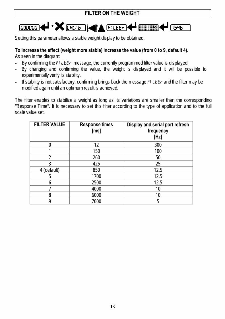
FILTER ON THE WEIGHT
Setting this parameter allows a stable weight display to be obtained.
To increase the effect (weight more stable) increase the value (from 0 to 9, default 4). As seen in the diagram: - By confirming the message, the currently programmed filter value is displayed. - By changing and confirming the value, the weight is displayed and it will be possible to
experimentally verify its stability. - If stability is not satisfactory, confirming brings back the message and the filter may be
modified again until an optimum result is achieved.
The filter enables to stabilize a weight as long as its variations are smaller than the corresponding “Response Time”. It is necessary to set this filter according to the type of application and to the full scale value set.
FILTER VALUE Response times [ms]
Display and serial port refresh frequency
[Hz]
0 12 300
1 150 100
2 260 50
3 425 25
4 (default) 850 12.5
5 1700 12.5
6 2500 12.5
7 4000 10
8 6000 10
9 7000 5

14
ZERO PARAMETERS
RESETTABLE WEIGHT SETTING FOR SMALL WEIGHT CHANGES
(from 0 to max full scale; default: 300; considered decimals: 300 – 30.0 – 3.00 – 0.300): this parameter indicates the maximum weight value resettable by external contact, keypad or serial protocol.
AUTOMATIC ZERO SETTING AT POWER-ON
(from 0 to max 20% of full scale; default: 0): If at switch-on the weight value is lower than the
value set in this parameter and does not exceed the value, the weight is reset. The zero setting will be lost when the instrument is turned off. To disable this function, set 0.
ZERO TRACKING
(from 1 to 5, default: ): When the zero weight value is stable and, after a second, it deviates from zero by a figure in divisions smaller or equal to the figure in divisions set in this parameter, the weight is set to zero. To disable this function, set . Example: if the parameter is set to 5 and is set to 2, the weight will be automatically set to zero for variations smaller than or equal to 10 ( x ).

15
Available unit of measure are:
: kilograms : grams : tons
: pounds* : Newton*
: liters* : bar* : atmospheres*
: pieces* : Newton meters*
: kilogram meters* : other generic units of measure not included in the list*
If the print function is enabled, the symbol corresponding to the selected unit of measure will be printed after the measured value.
For the units marked with * it’s possible to set also the display coefficient (parameter , see the related paragraph). To use is necessary to enable it, closing the input (see paragraph OUTPUTS AND INPUTS CONFIGURATION).
16
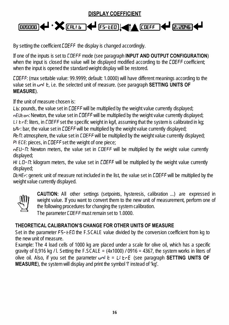
DISPLAY COEFFICIENT
By setting the coefficient the display is changed accordingly.
If one of the inputs is set to mode (see paragraph INPUT AND OUTPUT CONFIGURATION) when the input is closed the value will be displayed modified according to the coefficient; when the input is opened the standard weight display will be restored.
: (max settable value: 99.9999; default: 1.0000) will have different meanings according to the value set in , i.e. the selected unit of measure. (see paragraph SETTING UNITS OF MEASURE).
If the unit of measure chosen is: : pounds, the value set in will be multiplied by the weight value currently displayed;
: Newton, the value set in will be multiplied by the weight value currently displayed; : liters, in set the specific weight in kg/l, assuming that the system is calibrated in kg;
: bar, the value set in will be multiplied by the weight value currently displayed; : atmosphere, the value set in will be multiplied by the weight value currently displayed;
: pieces, in set the weight of one piece; : Newton meters, the value set in will be multiplied by the weight value currently
displayed; : kilogram meters, the value set in will be multiplied by the weight value currently
displayed; : generic unit of measure not included in the list, the value set in will be multiplied by the
weight value currently displayed.
CAUTION: All other settings (setpoints, hysteresis, calibration ...) are expressed in weight value. If you want to convert them to the new unit of measurement, perform one of the following procedures for changing the system calibration. The parameter must remain set to 1.0000.
THEORETICAL CALIBRATION’S CHANGE FOR OTHER UNITS OF MEASURE Set in the parameter the F.SCALE value divided by the conversion coefficient from kg to the new unit of measure. Example: The 4 load cells of 1000 kg are placed under a scale for olive oil, which has a specific gravity of 0,916 kg / l. Setting the F.SCALE = (4x1000) / 0916 = 4367, the system works in liters of olive oil. Also, if you set the parameter = (see paragraph SETTING UNITS OF MEASURE), the system will display and print the symbol ‘l’ instead of ‘kg’.

17
REAL CALIBRATION’S CHANGE FOR OTHER UNITS OF MEASURE Load a known quantity of product liters on the scale (equal to at least 50% of the maximum amount that you must weigh) and enter in the parameter , the product loaded value in liters. Also, if
you set the parameter = (see paragraph SETTING UNITS OF MEASURE), the system will display and print the symbol ‘l’ instead of ‘kg’.
OUTPUTS AND INPUTS CONFIGURATION
OUTPUTS The outputs are set by default as follows: / / / .
Possible operation modes:
- (normally open): the relay is de-energized and the contact is open when the weight is lower than the programmed setpoint value; it closes when the weight is higher than or equal to the programmed setpoint value.
- (normally closed): the relay is energized and the contact is closed when the weight is lower than the programmed setpoint value; it opens when the weight is higher than or equal to the programmed setpoint value.
- : the contact will switch on the basis of weight, according to setpoint (see paragraph SETPOINT PROGRAMMING).
- : the contact will not switch on the basis of weight, but is controlled by remote protocol commands.
- : relay switching occurs when the weight is stable.
- If the operation mode is selected, the following options are also active: - : the contact will switch on the basis of gross weight. - : the contact will switch on the basis of net weight (If the net function is not active, the
contact will switch on the basis of gross weight).
- : relay switching occurs for both positive and negative weight values. - : relay switching occurs for positive weight values only. - : relay switching occurs for negative weight values only.

18
By confirming with the setpoint operation can be set to value 0: - : relay switching will not occur if the setpoint value is ‘0’. - :
- Setpoint = ’0’ and = , relay switching occurs when the weight is ‘0’; the relay will switch again when the weight is different from zero, taking hysteresis into account (both for positive and for negative weights).
- Setpoint = ’0’ and = , relay switching occurs for a weight higher than or equal to ‘0’, the relay will switch again for values below ‘0’, taking hysteresis into account.
- Setpoint = ’0’ and = , relay switching occurs for a weight lower than or equal to‘0’, the relay will switch again for values above ‘0’, taking hysteresis into account.
INPUTS
Default: input 1 = input 2 =
Possible operation modes:
- (NET/GROSS): by closing this input for no more than one second, it’s making an operation of SEMI-AUTOMATIC TARE and the display will show the net weight. To display the gross weight again, hold the NET/GROSS input closed for 3 seconds.
- : by closing the input for no more than one second, the weight is set to zero (see paragraph SEMI-AUTOMATIC ZERO (WEIGHT ZERO-SETTING FOR SMALL VARIATIONS)).
- : keeping the input closed the maximum weight value reached remains on display. Opening the input the current weight is displayed.
- : closing the input no operation is performed, the input status may however be read remotely by way of the communication protocol.
- : closing the input for max one second the weight is transmitted over the serial connection according to the fast continuous transmission protocol only once (only if is set in the item ).
- : when the input is closed the weight is displayed based on the set coefficient (see setting of the units of measure and coefficient), otherwise the weight is displayed.
SEMI-AUTOMATIC TARE (NET/GROSS)
THE SEMI-AUTOMATIC TARE OPERATION IS LOST UPON INSTRUMENT POWER-OFF.
To perform a net operation (SEMI-AUTOMATIC TARE), close the NET/GROSS input or press the key for less than 3 seconds. The instrument displays the net weight (just set to zero) and the NET LED lights up. To display the gross weight again, keep the NET/GROSS input closed or press for 3 seconds. This operation can be repeated many times by the operator to allow the loading of several products.

19
Example of weighing fruit in a box: Put the box on the scale, the display shows the box weight, press and the display shows the net weight to zero; by introducing the fruit in the box, the display shows the fruit weight. This operation can be repeated several times.
During the net weight displaying, keep pressed the key to temporarily display the gross weight. As soon as the key is released, the net weight will be displayed again.
The semi-automatic tare operation is not allowed if the gross weight is zero.
PRESET TARE (SUBTRACTIVE TARE DEVICE)
It is possible to manually set a preset tare value to be subtracted from the display value provided that the ≤ max capacity condition is verified.
After setting the tare value, going back to the weight display, the display shows the net weight (subtracting the preset tare value) and the NET LED lights up to show that a tare has been entered. To delete a preset tare and return to gross weight display, hold down for about 3 seconds or keep the NET/GROSS input (if any) closed for the same length of time (3 seconds). The preset tare value is set to zero. The NET LED is turned off when the gross weight is displayed once again.
During the net weight displaying, keep pressed the key to temporarily display the gross weight. As soon as the key is released, the net weight will be displayed again.
- IF A SEMI-AUTOMATIC TARE (NET) IS ENTERED, IT IS NOT POSSIBLE TO ACCESS THE ENTER PRESET TARE FUNCTION.
- IF A PRESET TARE IS ENTERED, IT’S STILL POSSIBLE TO ACCESS THE SEMI- AUTOMATIC TARE (NET) FUNCTION. THE TWO DIFFERENT TYPES OF TARE ARE ADDED.
ALL THE SEMI-AUTOMATIC TARE (NET) AND PRESET TARE FUNCTIONS WILL BE LOST WHEN THE INSTRUMENT IS TURNED OFF.

20
SEMI-AUTOMATIC ZERO (WEIGHT ZERO-SETTING FOR SMALL VARIATIONS)
By closing the SEMI-AUTOMATIC ZERO input, the weight is set to zero. The zero setting will be lost when the instrument is turned off.
This function is only allowed if the weight is lower than the value (see section RESETTABLE WEIGHT SETTING FOR SMALL WEIGHT CHANGES), otherwise the alarm ˉˉˉˉˉ appears and the weight is not set to zero.
PEAK
Keeping the input closed the maximum weight value reached remains displayed. Opening the input the current weight is displayed.
If you wish to use this input to view a sudden variation peak, set the FILTER ON THE WEIGHT to 0.
SERIAL COMMUNICATION SETTINGS
According to the chosen protocol only the necessary settings will be displayed in sequence (see diagram here above).
- : communication port.
- : it disables any type of communication (default). - : MODBUS-RTU protocol; possible addresses: from 1 to 99 (see Communication
Protocols). - : ASCII bidirectional protocol; possible addresses: from 1 to 99 (see Communication
protocols). - -

21
- : continuous weight transmission protocol (see Communication protocols manual),
at the frequency set in item (from 10 to 300). - (set: ). - (set: ).
- : continuous weight transmission protocol to RIP5/20/60, RIP50SHA, RIPLED series remote displays; the remote display shows the net weight or gross weight according to its settings (set: ).
- : continuous weight transmission protocol to RIP675, RIP6125C series remote displays; the remote display shows the net weight or gross weight according to its settings (set: ).
- : continuous weight transmission protocol to RIP675, RIP6125C series remote displays (set: ). When the remote display is set to gross weight: - if the instrument displays the gross weight, the remote display shows the gross weight. - if the instrument shows the net weight the remote display shows the net weight
alternated with the message ‘ '. - : transmission speed (2400, 4800, 9600, 19200, 38400, 115200; default:
9600). - : instrument’s address (from 1 to 99; default: 1). - : maximum transmission frequency (10 – 20 – 30 – 40 – 50 – 60 – 70 – 80 – 100 – 200 – 300; default: 10); to be set when the transmission protocol is selected. Maximum setting frequency ( ): - 20Hz with minimum baud rate 2400 baud. - 40Hz with minimum baud rate 4800 baud. - 80Hz with minimum baud rate 9600 baud. - 100Hz with minimum baud rate 19200 baud. - 200Hz with minimum baud rate 38400 baud. - 300Hz with minimum baud rate 38400 baud.
- : delay in milliseconds which elapses before the instrument replies (from 0 to 200 msec; default: 0).
- : - : parity none (default).
- : even parity. - : odd parity.
- : stop bit (1 – 2; default: 1).

22
RS485 SERIAL COMMUNICATION
If the RS485 network exceeds 100 meters in length or baud-rate over 9600 are used, close the two jumpers, called "RS-485 termination", to activate two 120 ohm terminating resistors between the ‘+’ and ‘–’ terminals of the line, on the terminal strip of the furthest instruments. Should there be different instruments or converters, refer to the specific manuals to determine whether it is necessary to connect the above-mentioned resistors.
DIRECT CONNECTION BETWEEN RS485 AND RS232 WITHOUT CONVERTER
Since a two-wire RS485 output may be used directly on the RS-232 input of a PC or remote display, it is possible to implement instrument connection to an RS-232 port in the following manner:
INSTRUM RS232
RS 485 - → RXD
RS 485 + → GND
This type of connection allows A SINGLE instrument to be used in a ONE WAY mode.

23
TEST
- Input Test: : ensure that for each open input is displayed, is displayed when the input is closed.
- Output Test: : setting ensure that the corresponding output opens. Setting ensure that the
corresponding output closes. - Millivolt Test:
: displays the load cell response signal in mV with four decimals.
SETPOINTS PROGRAMMING
From the weight display, press to access the setpoints setting. : to enter a menu, confirm the data entry.
: to modify the displayed value or menu item. : to select a new value or modify the displayed menu item. : to cancel and return to the previous menu.
- (from 0 to max full scale; default: 0): Setpoint; relay switching occurs when the weight exceed the value set in this parameter. The type of switching is settable (see paragraph OUTPUTS AND INPUTS CONFIGURATION).
- (from 0 to max full scale; default: 0): Hysteresis, value to be subtracted from the setpoint to obtain contact switching for decreasing weight. For example with a setpoint at 100 and hysteresis at 10, the switching occurs at 90 for decreasing weight.
These values are set to zero if the calibration is changed significantly (see paragraphs THEORETICAL CALIBRATION and REAL CALIBRATION (WITH SAMPLE WEIGHTS).

24
ALARMS
: the load cell is not connected or is incorrectly connected; the load cell signal exceeds 39 mV; the conversion electronics (AD converter) is malfunctioning; the load cell is a 4-wire and there are no jumpers between EX- and REF- and between EX+ and REF+.
: the weight display exceeds 110% of the full scale. : internal instrument converter failure; check load cell connections, if necessary contact
Technical Assistance. : the weight exceeds the maximum weight by 9 divisions.
: maximum displayable value exceeded (value higher than 999999 or lower than -999999). : weight too high: zero setting not possible.
: this message appears in the sample weight setting, in real calibration, after the fifth sample weight value has been entered.
: the value set for the parameter is beyond the permitted values; press to quit the setting mode leaving the previous value unchanged. Examples: a number of decimals is selected for full scale which exceeds the instrument's display potential; value above the maximum setting value; the weight value set in sample weight verification does not match the detected mV increase.
: lock active on menu item, keypad or display. : It’s not possible to display properly the number because is greater than 999999 or less
than -999999.
Serial protocols alarms:
MODE Bit LSB 76543210
xxxxxxx1 76543210 xxxx1xxx
76543210 xxxxxx1x
76543210 xxxxx1xx
76543210 On gross: xxx1xxxx On net: xx1xxxxx
The response to the zero command is a 'value not valid' error (error code 3)
Status Register MODBUS RTU
ASCII O-F_ O-L_ O-F_ O-L_ O-F_ &aa#CRRIP * O-F_ O-L_ O-F_ O-L_ O-F_ O-F_
HDRIP-N _ERCEL _ER_OL _ER_AD ###### _ER_OF O SETCONTIN _ERCEL _ER_OL _ER_AD ^^^^^^ _ER_OF O SET
* For RIP remote displays, if the message exceeds 5 digits the display reads .
If an alarm becomes active the relays open.
25
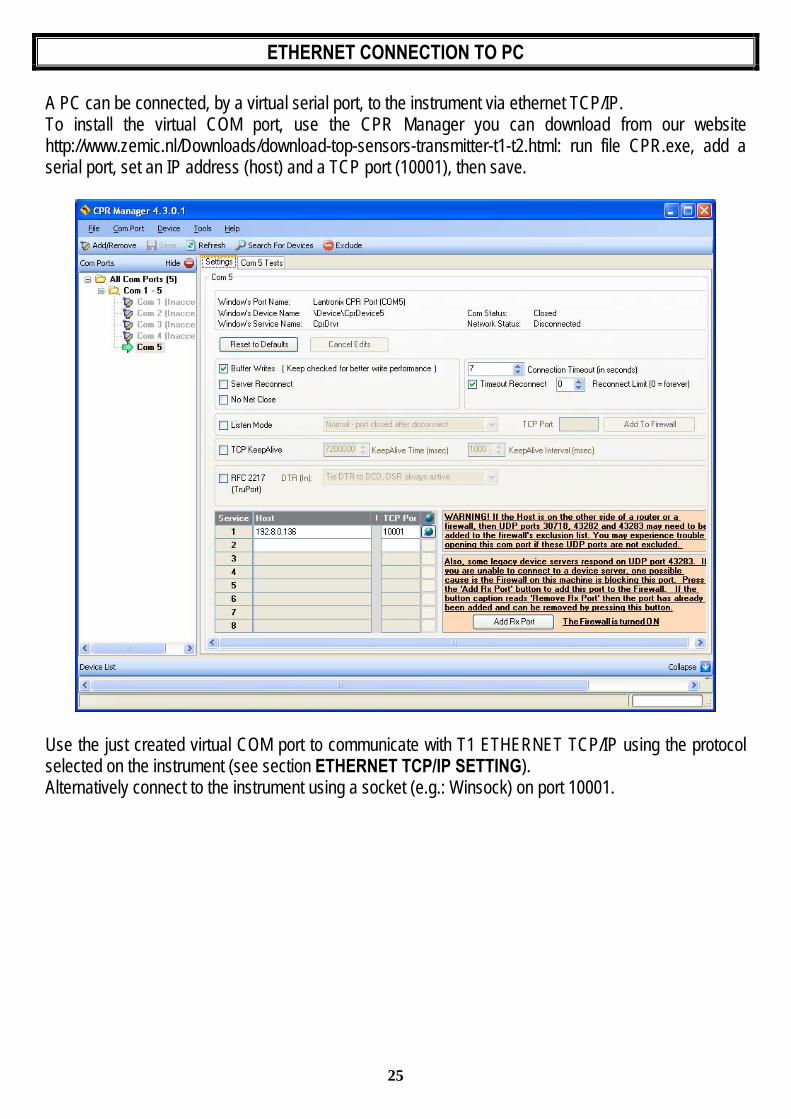
ETHERNET CONNECTION TO PC
A PC can be connected, by a virtual serial port, to the instrument via ethernet TCP/IP. To install the virtual COM port, use the CPR Manager you can download from our website http://www.zemic.nl/Downloads/download-top-sensors-transmitter-t1-t2.html: run file CPR.exe, add a serial port, set an IP address (host) and a TCP port (10001), then save.
Use the just created virtual COM port to communicate with T1 ETHERNET TCP/IP using the protocol selected on the instrument (see section ETHERNET TCP/IP SETTING). Alternatively connect to the instrument using a socket (e.g.: Winsock) on port 10001.

26
DIAGNOSTIC To verify the ethernet configuration of T1 ETHERNET TCP/IP, you can install the application Lantronix DeviceInstaller, you can download this from our website http://www.zemic.nl/Downloads/download-top-sensors-transmitter-t1-t2.html, on a PC with Microsoft Windows operating system. Connect PC and instrument via LAN (point-to-point or through hub/switch), run the application and click on Search:
Select the found device and click on Telnet Configuration tab; click on Connect, and then press Enter on keyboard.
Press 0 to change server settings: change only the 4 fields of IP address and confirm the other parameters by pressing Enter. Set a static IP address.

27
WEBSITE
Set operation mode (see section ETHERNET TCP/IP SETTING) and restart the instrument to apply changes. Open your web browser and point to the instrument address to be monitored; it will open the following page:
Enter “TOPSENSOR” as user name and the password supplied with the instrument in respective fields, then press Login to enter the status page:
In case of incorrect parameter setting, the “INSTRUMENT DATA READING ERROR” message is displayed.
28
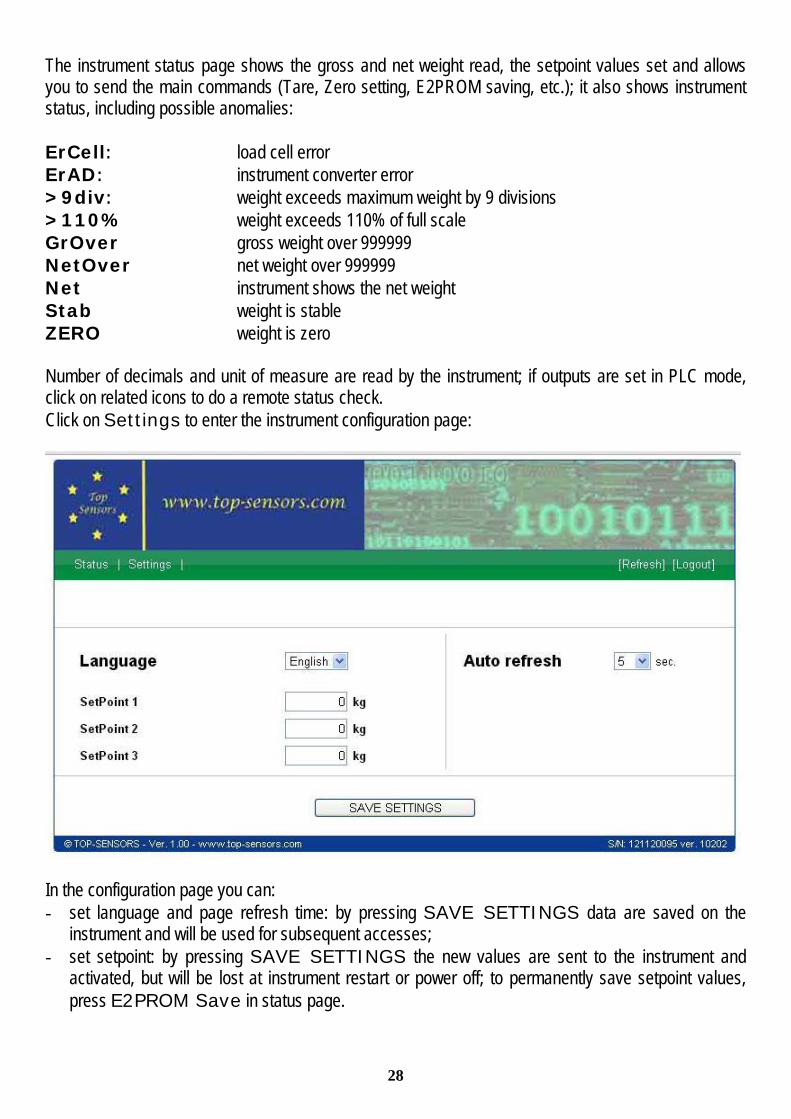
The instrument status page shows the gross and net weight read, the setpoint values set and allows you to send the main commands (Tare, Zero setting, E2PROM saving, etc.); it also shows instrument status, including possible anomalies: ErCell: load cell error ErAD: instrument converter error >9div: weight exceeds maximum weight by 9 divisions >110% weight exceeds 110% of full scale GrOver gross weight over 999999 NetOver net weight over 999999 Net instrument shows the net weight Stab weight is stable ZERO weight is zero Number of decimals and unit of measure are read by the instrument; if outputs are set in PLC mode, click on related icons to do a remote status check. Click on Settings to enter the instrument configuration page:
In the configuration page you can: - set language and page refresh time: by pressing SAVE SETTINGS data are saved on the
instrument and will be used for subsequent accesses; - set setpoint: by pressing SAVE SETTINGS the new values are sent to the instrument and
activated, but will be lost at instrument restart or power off; to permanently save setpoint values, press E2PROM Save in status page.

29
FAST CONTINUOUS TRANSMISSION PROTOCOL
This protocol allows for automatic weight reception via a serial connection at high update frequencies. Up to 300 strings per second are transmitted (with a minimum transmission rate of 38400 baud). Following communication modes available (see paragraph SERIAL COMMUNICATION SETTINGS): - : communication compatible with TX RS485 instruments; - : communication compatible with TD RS485 instruments.
- If is set, the following string is transmitted to PC/PLC: xxxxxxCRLF
in which: xxxxxx = 6 ASCII characters for gross weight (48 57 ASCII). CR = 1 character of back to start (13 ASCII). LF = 1 character of new line (10 ASCII).
In case of negative weight, the first character on the left acquires the value « - » (minus sign - ASCII 45). In case of error or alarm, the 6 weight characters are replaced by the messages found in the table of the ALARMS.
- If is set, the following string is transmitted to PC/PLC: &TzzzzzzPzzzzzz\ckckCR
in which: & = 1 character of string beginning (38 ASCII). T = 1 character of gross weight identification. P = 1 character of gross weight identification. zzzzzz = 6 characters of gross weight (48 57 ASCII). \ = 1 character of separation (92 ASCII). ckck = 2 ASCII control characters calculated considering that the characters between & and \ are excluded. The control value is obtained by carrying out the XOR (or exclusive) operation for the 8 bit ASCII codes of the characters considered. A character expressed in hexadecimal is thus obtained, with 2 digits which may acquire values from “0” to “9” and from “A” to “F”. “ckck” is the ASCII code of the two hexadecimal digits. CR = 1 character for string end (13 ASCII).
In case of negative weight, the first character on the left acquires the value « - » (minus sign - ASCII 45).
In case of error or alarm, the 6 gross weight characters are replaced by the messages found in the table of the ALARMS.
FAST TRANSMISSION VIA EXTERNAL CONTACT: it’s possible to transmit the weight, just once, even closing an input for no more than a second (see paragraphs OUTPUTS AND INPUTS CONFIGURATION and SERIAL COMMUNICATION SETTINGS).

30
CONTINUOUS TRANSMISSION PROTOCOL TO REMOTE DISPLAYS
Using this protocol, the instrument transmits, in continuous, the weight to remote displays; the communication string is transmitted 10 times per second. Following communication modes available (see paragraph SERIAL COMMUNICATION SETTINGS):
- : communication with remote displays series RIP5/20/60, RIP50SHA, RIPLED; remote display shows the net or gross weight, depending on the remote display setting.
- : communication with remote displays series RIP675, RIP6125C; remote display shows the net or gross weight, depending on the remote display setting.
- : communication with remote displays series RIP675, RIP6125C.
The instrument sends the following string to the remote display:
&NxxxxxxLyyyyyy\ckckCR
in which: & = 1 character of string beginning (38 ASCII). N = 1 character of net weight identification (78 ASCII). xxxxxx = 6 characters for net or PEAK weight if present (48 57 ASCII). L = 1 character of gross weight identification (76 ASCII). yyyyyy = 6 characters for gross weight (48 57 ASCII). \ = 1 character for separation (92 ASCII). ckck = 2 ASCII control characters calculated considering that the characters between “&” and “\” are excluded. The control value is obtained by carrying out the XOR (or exclusive) operation for the 8 bit ASCII codes of the characters considered. Character expressed in hexadecimal is thus obtained, with 2 digits which may acquire values from “0” to “9” and from ”A” to “F”. “ckck” is the ASCII code of the two hexadecimal digits. CR = 1 character for string end (13 ASCII).
In case of negative weight, the first character on the left acquires the value « - » (minus sign - ASCII 45).
If the protocol on has been set, the decimal point at the position shown on the instrument's display can also be transmitted. In this case, if the value exceeds 5 digits, only the 5 most significant digits are transmitted, while if the value is negative, no more than the 4 most significant digits are transmitted. In both cases, however, the decimal point shifts consistently with the value to display. If has been set, in addition to what stated in protocol, the instrument transmits the prompt every 4 seconds in the gross weight field, if on the instrument, it has been carried out a net operation (see paragraph SEMI-AUTOMATIC TARE (NET/GROSS)). In case of weight value is under -99999, the minus sign (‘-‘) is sent alternated with the most significant figure.
In case of error or alarm, the 6 characters of the gross and net weight are replaced by the messages found in the table of the ALARMS.
31
ASCII BIDIRECTIONAL PROTOCOL
The instrument replies to the requests sent from a PC/PLC. It is possible to set a waiting time for the instrument before it transmits a response (see
parameter in the paragraph SERIAL COMMUNICATION SETTINGS). Following communication modes available (see paragraph SERIAL COMMUNICATION SETTINGS):
: communication compatible with W60000, WL60 Base, WT60 Base, TLA60 Base instruments;
: communication compatible with TD RS485 instruments.
Captions: $: Beginning of a request string (36 ASCII); & o &&: Beginning of a response string (38 ASCII); aa: 2 characters for instrument address (48 57 ASCII); !: 1 character to indicate the correct reception(33 ASCII); ?: 1 character to indicate a reception error (63 ASCII); #: 1 character to indicate an error in the command execution (23 ASCII); ckck: 2 ASCII characters for Check-Sum (for further information, see paragraph CHECK- SUM CALCULATION); CR: 1 character for string end (13 ASCII); \: 1 character for separation (92 ASCII).
1. SETPOINT VALUES SETTING:
The PC transmits : $aaxxxxxxyckckCR
in which: xxxxxx = 6 characters for the setpoint value (48 57 ASCII); y = A (set the value in the Setpoint 1) y = B (set the value in the Setpoint 2) y = C (set the value in the Setpoint 3)
Possible instrument responses:
- correct reception: &&aa!\ckckCR - incorrect reception: &&aa?\ckckCR
2. SETPOINTS STORAGE INTO EEPROM MEMORY:
The sepoints value relevant to the two setpoints programmed via the PC are stored to the RAM volatile memory and lost upon instrument power off. It is necessary to send a special command to save them permanently in the EEPROM memory. Please note that the writing number allowed in the EEPROM memory is limited (about 100000).
32
The PC transmits: $aaMEMckckCR
Possible instrument responses: - correct reception: &&aa!\ckckCR - incorrect reception: &&aa?\ckckCR
3. READING WEIGHT, THE SETPOINT AND THE PEAK (IF PRESENT) FROM THE PC:
The PC transmits: $aajckckCR
in which: j = a to read setpoint 1 j = b to read setpoint 2 j = c to read setpoint 3 j = t to read gross weight j = n to read net weight j = p to read the gross weight peak if the parameter is set as ; if,
instead, the parameter is set on the gross weight will be read. To read the points, set the equal to 50000.
Possible instrument responses:
- correct reception: &aaxxxxxxj\ckckCR - incorrect reception: &&aa?\ckckCR - if the peak is not configured: &aa#CR
in which: xxxxxx = 6 value characters of the required weight;
Notes: In case of negative weight, the first character on the left acquires the value « - » (minus sign - ASCII 45). In case of weight value is under -99999, the minus sign (‘-‘) is sent alternated with the most significant figure.
Error messages: In case of an instrument alarm for exceeding 110% of the full scale or 9 divisions above the value of the parameter , the instrument sends the string:
&aassO-Lst\ckck
In case of faulty connection of the load cells or of another alarm, the instrument sends:
&aassO-Fst\ckck
in which: s = 1 separator character (32 ASCII – space-).
Generally refer to the ALARMS paragraph in this manual.

33
4. SEMI-AUTOMATIC ZERO (WEIGHT ZERO-SETTING FOR SMALL VARIATIONS) CAUTION: CAUTION: The zero-setting will not be maintained after an instrument power-off. The PC transmits: $aaZEROckckCR
Possible instrument responses: - correct reception: &&aa!\ckckCR
- incorrect reception: &&aa?\ckckCR - the current weight is over the maximum value resettable: &aa#CR
5. SWITCHING FROM GROSS WEIGHT TO NET WEIGHT
The PC transmits: $aaNETckckCR
Possible instrument responses: - correct reception: &&aa!\ckckCR
- incorrect reception: &&aa?\ckckCR 6. SWITCHING FROM NET WEIGHT TO GROSS WEIGHT
The PC transmits: $aaGROSSckckCR
Possible instrument responses: - correct reception: &&aa!\ckckCR
- incorrect reception: &&aa?\ckckCR
7. READING OF DECIMALS AND NUMBER OF DIVISIONS
The PC transmits: $aaDckckCR
Possible instrument responses: - correct reception: &aaxy\ckckCR
- incorrect reception: &&aa?\ckckCR
in which: x = number of decimals y = division value
The y field acquires the following values: '3' for division value = 1; '4' for division value = 2; '5' for division value = 5; '6' for division value = 10; '7' for division value = 20; '8' for division value = 50; '9' for division value = 100;

34
8. TARE WEIGHT ZERO SETTING
The PC transmit he following ASCII string containing the zeroing command:: $aazckckCR in which: z = weight zeroing command (122 ASCII)
Possible instrument responses: - correct reception: &aaxxxxxxt\ckckCR - incorrect reception: &&aa?\ckckCR - If the instrument is not in gross weight displaying condition, the response is: &aa#CR
in which: xxxxxx = 6 characters for the required weight value; t = weight identification code (116 ASCII).
Example: Weight zero setting for instrument with address 2:
For the calibration, make sure that the scale is empty and the instrument measures a corresponding mV signal.
query: $02z78(Cr) response: &02000000t\76(Cr) In case of correct weight zero setting the read value (response) must be 0 (in the string “000000”).
The zero values are stored to the EEPROM memory, please note that the writing number allowed is limited (about 100000). If it is necessary to reset the weight quite often, it is recommended to perform it by PC or PLC program, keeping in mind the weight deviation respect to the zero instrument.
9. REAL CALIBRATION (WITH SAMPLE WEIGHTS)
After having performed the TARE WEIGHT ZERO SETTING, this function allows correct calibration to be done using sample weights of known value and, if necessary, any deviations of the indicated value from the correct value to be corrected.
Load onto the weighing system a sample weight, which must be at least 50% of the Full Scale otherwise make sure that the instrument measures a corresponding mV signal
The PC sends the following ASCII string containing the calibration command: $aasxxxxxxckckCR in which: s = calibration command (115 ASCII)
xxxxxx = 6 characters for sample weight value.

35
Possible instrument responses: - correct reception: &aaxxxxxxt\ckckCR - incorrect reception or full scale equal to zero: &&aa?\ckckCR
in which: t = gross weight identification code (116 ASCII). xxxxxx = 6 characters to indicate the current weight value.
In case of correct calibration, the read value must be equal to sample weight.
Example: Calibration for instrument with address 1 and sample weight of 20000 kg:
query: $01s02000070(Cr) response: &01020000t\77(Cr)
In case of correct calibration the read value has to be “020000”. 10. KEYPAD LOCK (ACCESS PROTECTION TO THE INSTRUMENT)
The PC transmits: $aaKEYckckCR
Possible instrument responses: - correct reception: &&aa!\ckckCR - incorrect reception: &&aa?\ckckCR
11. KEYPAD UNLOCK
The PC transmits: $aaFREckckCR
Possible instrument responses: - correct reception: &&aa!\ckckCR - incorrect reception: &&aa?\ckckCR
12. DISPLAY AND KEYPAD LOCK
The PC transmits: $aaKDISckckCR
Possible instrument responses: - correct reception: &&aa!\ckckCR - incorrect reception: &&aa?\ckckCR

36
CHECK-SUM CALCULATION
The two ASCII control characters (ckck) are the representation of a hexadecimal digit in ASCII characters. The check digit is calculated by performing the operation XOR (exclusive or) 8-bit ASCII codes of the only part of the underlined string.
The procedure to calculate the check- sum is the following: - Consider only the string characters highlighted with underlining; - Calculate the EXCLUSIVE OR (XOR) of the ASCII codes for the characters;
Example: character decimal ASCII code hexadecimal ASCII code binary ASCII code
0 1 t
48 49
116
30 31 74
00110000 00110001 01110100
XOR = 117 75 01110101 - The result of the XOR operation expressed in hexadecimal notation is made up of 2 hexadecimal
digits (numbers from 0 to 9 or letters from A to F). In this case the hexadecimal code is 0x75.
- The check-sum inserted in the strings transmitted is made up of the 2 characters which represent the result of the XOR operation in hexadecimal notation (in our example the character " 7 " and the character " 5).
37
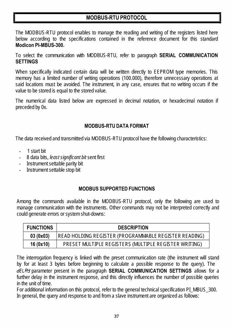
MODBUS-RTU PROTOCOL
The MODBUS-RTU protocol enables to manage the reading and writing of the registers listed here below according to the specifications contained in the reference document for this standard Modicon PI-MBUS-300.
To select the communication with MODBUS-RTU, refer to paragraph SERIAL COMMUNICATION SETTINGS
When specifically indicated certain data will be written directly to EEPROM type memories. This memory has a limited number of writing operations (100.000), therefore unnecessary operations at said locations must be avoided. The instrument, in any case, ensures that no writing occurs if the value to be stored is equal to the stored value.
The numerical data listed below are expressed in decimal notation, or hexadecimal notation if preceded by 0x.
MODBUS-RTU DATA FORMAT
The data received and transmitted via MODBUS-RTU protocol have the following characteristics:
- 1 start bit - 8 data bits, least significant bit sent first - Instrument settable parity bit - Instrument settable stop bit
MODBUS SUPPORTED FUNCTIONS
Among the commands available in the MODBUS-RTU protocol, only the following are used to manage communication with the instruments. Other commands may not be interpreted correctly and could generate errors or system shut-downs:
FUNCTIONS DESCRIPTION
03 (0x03) READ HOLDING REGISTER (PROGRAMMABLE REGISTER READING)
16 (0x10) PRESET MULTIPLE REGISTERS (MULTIPLE REGISTER WRITING)
The interrogation frequency is linked with the preset communication rate (the instrument will stand by for at least 3 bytes before beginning to calculate a possible response to the query). The
parameter present in the paragraph SERIAL COMMUNICATION SETTINGS allows for a further delay in the instrument response, and this directly influences the number of possible queries in the unit of time. For additional information on this protocol, refer to the general technical specification PI_MBUS_300. In general, the query and response to and from a slave instrument are organized as follows:

38
FUNCTION 3: Read holding registers (PROGRAMMABLE REGISTER READING)
QUERY Address Function Add. Register1 No. register 2 bytes
A 0x03 0x0000 0x0002 CRC
Tot. bytes = 8
RESPONSE Address Function No. bytes Register1 Register 2 2 bytes
A 0x03 0x04 0x0064 0x00C8 CRC
Tot. bytes = 3+2*No. registers+2
in which: No. registers= number of Modbus register to be read, starting from the Address 1° register; No. bytes = number of data bytes to follow;
FUNCTION 16: Preset multiple registers (MULTIPLE REGISTER WRITING)
QUERY Address Function Add. reg. 1 No. reg. No. bytes Val. reg.1 Val.reg.2 2 bytes
A 0x10 0x0000 0x0002 0x04 0x0000 0x0000 CRC
Tot. bytes = 7+2*No. registers+2
RESPONSE Address Function Add. reg. 1 No. reg. 2 bytes
A 0x10 0x0000 0x0002 CRC
Tot. bytes = 8
Where: No. registers = number of Modbus register to be read, starting from the Address 1° register; No. bytes = number of data bytes to follow;
Val.reg.1 = register contents beginning from the first.
The Response contains the number of records changed starting from the Address 1° register.
COMMUNICATION ERROR MANAGEMENT
The communication strings are controlled by CRC (Cyclical Redundancy Check). In case of a communication error the slave will not respond with any string. The master must allow for a time-out before response reception. If no response is received it infers that a communication error has occurred.
In the event of a string received correctly but not executable, the slave responds with an EXCEPTIONAL RESPONSE. The "FUNCTION" field is transmitted with the msb at 1.

39
EXCEPTIONAL RESPONSE Address Function Code 2 bytes
A Funct + 0x80 CRC
CODE DESCRIPTION
1 ILLEGAL FUNCTION (Function not valid or not supported) 2 ILLEGAL DATA ADDRESS (The specified data address is not available) 3 ILLEGAL DATA VALUE (The data received have no valid value)
LIST OF USABLE REGISTERS
The MODBUS-RTU protocol implemented on this instrument can manage a maximum of 32 registers read and written in a single query or response.
R = the register can be read only W = the register can be written only R/W = the register can be both read and written H = high half of the DOUBLE WORD forming the number L = low half of the DOUBLE WORD forming the number
REGISTER DESCRIPTION Saving to EEPROM ACCESS 40001 Firmware version - R 40002 Type of instrument - R 40003 Year of production - R 40004 Serial Number - R 40005 Active program - R 40006 COMMAND REGISTER NO W 40007 STATUS REGISTER - R 40008 GROSS WEIGHT H - R 40009 GROSS WEIGHT L - R 40010 NET WEIGHT H - R 40011 NET WEIGHT L - R 40012 PEAK WEIGHT H - R 40013 PEAK WEIGHT L - R 40014 Divisions and units of measure - R 40015 Coefficient H R 40016 Coefficient L R 40017 SETPOINT 1 H
Only after command '99' Of the
COMMAND REGISTER R/W
40018 SETPOINT 1 L 40019 SETPOINT 2 H 40020 SETPOINT 2 L 40021 SETPOINT 3 H 40022 SETPOINT 3 L

40
40023 HYSTERESIS 1 H 40024 HYSTERESIS 1 L 40025 HYSTERESIS 2 H 40026 HYSTERESIS 2 L 40027 HYSTERESIS 3 H 40028 HYSTERESIS 3 L 40029 INPUTS - R 40030 OUTPUTS NO R/W 40037 Sample weight for calibration H Use with command '101' of
the COMMAND REGISTER R/W
40038 Sample weight for calibration L CAUTION: At the time of writing, the setpoint and hysteresis values, are saved to the RAM and will be lost upon the next power-off; to store them permanently to the EEPROM so that they are maintained at power-on, the 99 command of the Command Register must be sent.
REAL CALIBRATION COMMANDS (WITH SAMPLE WEIGHTS)
The instrument calibration can be changed via MODBUS. To carry out this procedure, the system must be unloaded and the weight value display reset to zero with the command ‘100’ of the Command Register. Then, a load must be placed on the system and the correct weight value must be sent to the registers 40037-40038; to save this value, send the control ‘101’ from the Command Register. If the operation is successfully completed, the two sample weight registers are set to zero.
STATUS REGISTER (40007)
Bit 0 Cell Error Bit 1 AD Convertor Malfunction
Bit 2 Maximum weight exceeded by 9 divisions
Bit 3 Gross weight higher than 110% of full scale
Bit 4 Gross weight beyond 999999 or less than -999999
Bit 5 Net weight beyond 999999 or less than -999999
Bit 6
Bit 7 Gross weight negative sign
Bit 8 Net weight negative sign
Bit 9 Peak weight negative sign
Bit 10 Net display mode
Bit 11 Weight stability
Bit 12 Weight within +/-¼ of a division around ZERO
Bit 13
Bit 14
Bit 15
41
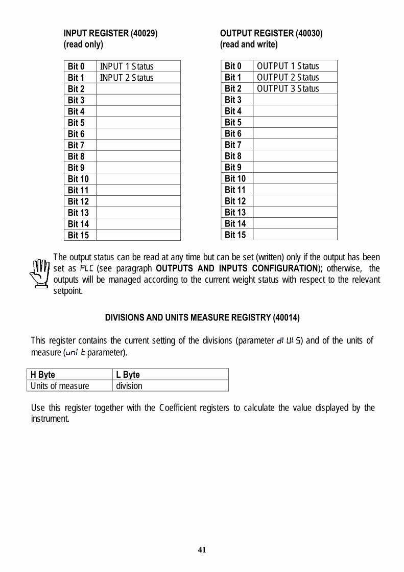
Bit 0 OUTPUT 1 Status
Bit 1 OUTPUT 2 Status
Bit 2 OUTPUT 3 Status
Bit 3
Bit 4
Bit 5
Bit 6
Bit 7
Bit 8
Bit 9
Bit 10
Bit 11
Bit 12
Bit 13
Bit 14
Bit 15
INPUT REGISTER (40029) OUTPUT REGISTER (40030) (read only) (read and write)
Bit 0 INPUT 1 Status
Bit 1 INPUT 2 Status
Bit 2
Bit 3
Bit 4
Bit 5
Bit 6
Bit 7
Bit 8
Bit 9
Bit 10
Bit 11
Bit 12
Bit 13
Bit 14
Bit 15
The output status can be read at any time but can be set (written) only if the output has been set as (see paragraph OUTPUTS AND INPUTS CONFIGURATION); otherwise, the outputs will be managed according to the current weight status with respect to the relevant setpoint.
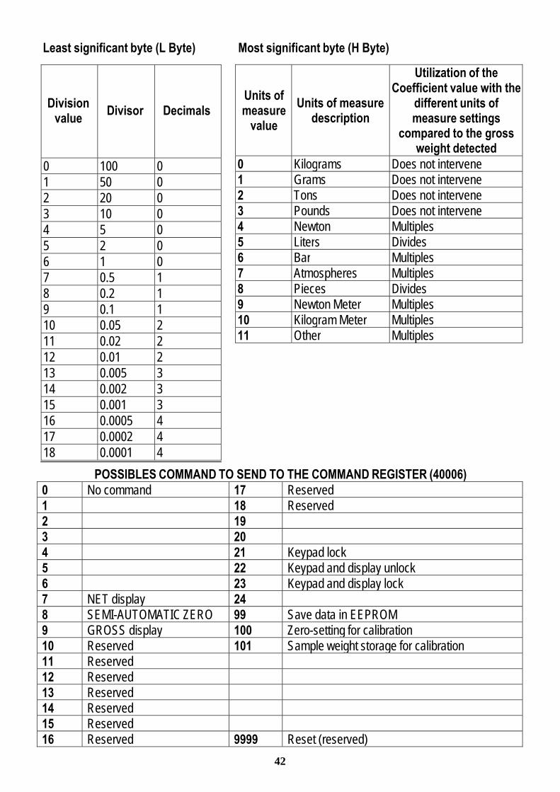
DIVISIONS AND UNITS MEASURE REGISTRY (40014)
This register contains the current setting of the divisions (parameter ) and of the units of measure ( parameter).
H Byte L Byte
Units of measure division
Use this register together with the Coefficient registers to calculate the value displayed by the instrument.
42
Units of measure
value
Units of measure
description
Utilization of the Coefficient value with the
different units of measure settings
compared to the gross weight detected
0 Kilograms Does not intervene
1 Grams Does not intervene
2 Tons Does not intervene
3 Pounds Does not intervene
4 Newton Multiples
5 Liters Divides
6 Bar Multiples
7 Atmospheres Multiples
8 Pieces Divides
9 Newton Meter Multiples
10 Kilogram Meter Multiples
11 Other Multiples
Least significant byte (L Byte) Most significant byte (H Byte)
POSSIBLES COMMAND TO SEND TO THE COMMAND REGISTER (40006) 0 No command 17 Reserved
1 18 Reserved
2 19
3 20
4 21 Keypad lock
5 22 Keypad and display unlock
6 23 Keypad and display lock
7 NET display 24
8 SEMI-AUTOMATIC ZERO 99 Save data in EEPROM
9 GROSS display 100 Zero-setting for calibration
10 Reserved 101 Sample weight storage for calibration
11 Reserved
12 Reserved
13 Reserved
14 Reserved
15 Reserved
16 Reserved 9999 Reset (reserved)
Division
value
Divisor
Decimals
0 100 0
1 50 0
2 20 0
3 10 0
4 5 0
5 2 0
6 1 0
7 0.5 1
8 0.2 1
9 0.1 1
10 0.05 2
11 0.02 2
12 0.01 2
13 0.005 3
14 0.002 3
15 0.001 3
16 0.0005 4
17 0.0002 4
18 0.0001 4
43
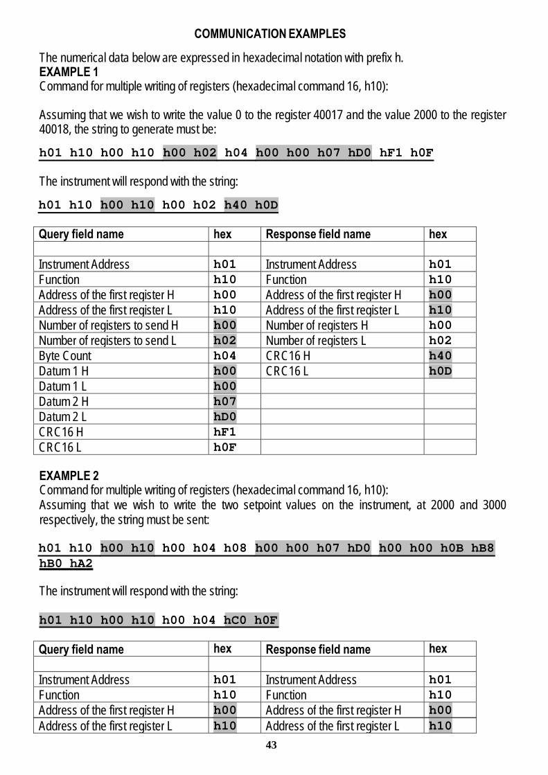
COMMUNICATION EXAMPLES
The numerical data below are expressed in hexadecimal notation with prefix h. EXAMPLE 1 Command for multiple writing of registers (hexadecimal command 16, h10):
Assuming that we wish to write the value 0 to the register 40017 and the value 2000 to the register 40018, the string to generate must be:
h01 h10 h00 h10 h00 h02 h04 h00 h00 h07 hD0 hF1 h0F
The instrument will respond with the string: h01 h10 h00 h10 h00 h02 h40 h0D
Query field name hex Response field name hex
Instrument Address h01 Instrument Address h01
Function h10 Function h10
Address of the first register H h00 Address of the first register H h00
Address of the first register L h10 Address of the first register L h10
Number of registers to send H h00 Number of registers H h00
Number of registers to send L h02 Number of registers L h02
Byte Count h04 CRC16 H h40
Datum 1 H h00 CRC16 L h0D
Datum 1 L h00
Datum 2 H h07
Datum 2 L hD0
CRC16 H hF1
CRC16 L h0F
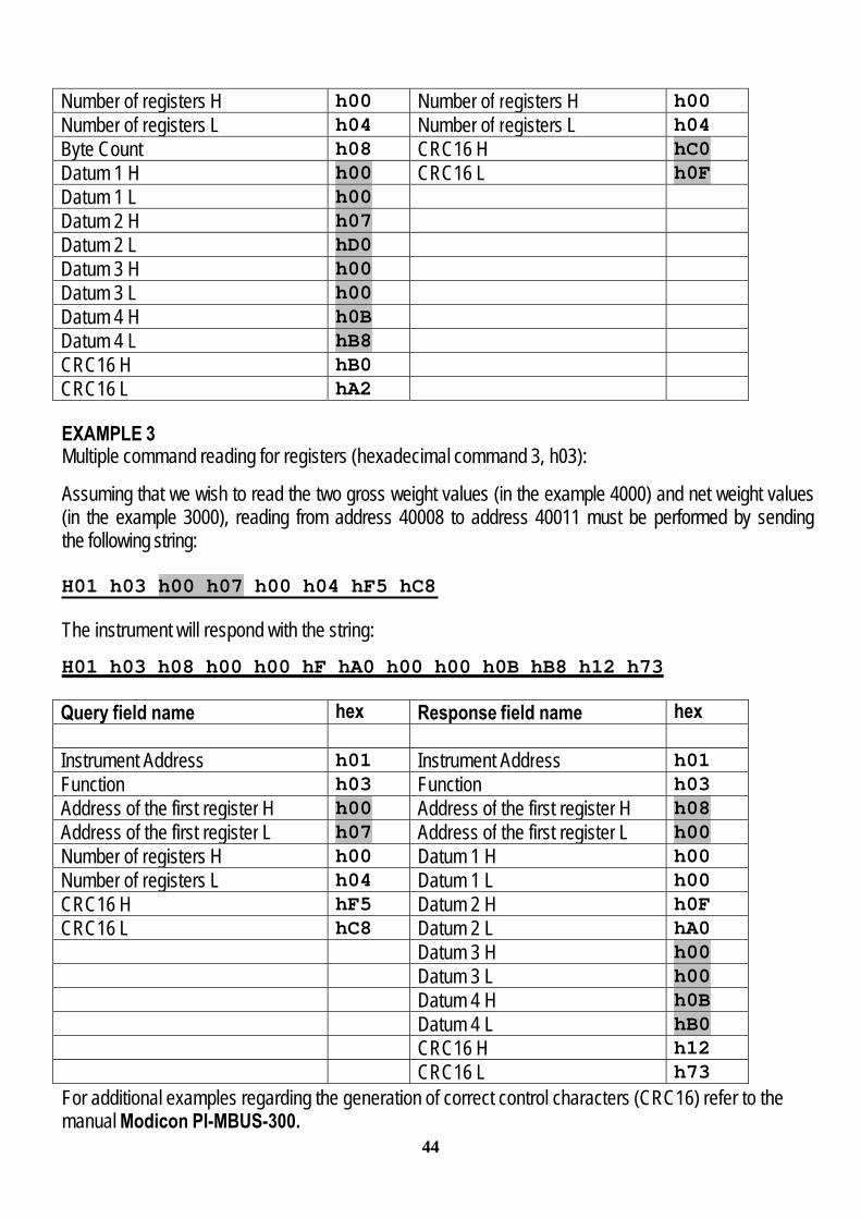
EXAMPLE 2 Command for multiple writing of registers (hexadecimal command 16, h10): Assuming that we wish to write the two setpoint values on the instrument, at 2000 and 3000 respectively, the string must be sent:
h01 h10 h00 h10 h00 h04 h08 h00 h00 h07 hD0 h00 h00 h0B hB8hB0 hA2
The instrument will respond with the string:
h01 h10 h00 h10 h00 h04 hC0 h0F
Query field name hex Response field name hex
Instrument Address h01 Instrument Address h01
Function h10 Function h10
Address of the first register H h00 Address of the first register H h00
Address of the first register L h10 Address of the first register L h10
44
Number of registers H h00 Number of registers H h00
Number of registers L h04 Number of registers L h04
Byte Count h08 CRC16 H hC0
Datum 1 H h00 CRC16 L h0F
Datum 1 L h00
Datum 2 H h07
Datum 2 L hD0
Datum 3 H h00
Datum 3 L h00
Datum 4 H h0B
Datum 4 L hB8
CRC16 H hB0
CRC16 L hA2
EXAMPLE 3 Multiple command reading for registers (hexadecimal command 3, h03):
Assuming that we wish to read the two gross weight values (in the example 4000) and net weight values (in the example 3000), reading from address 40008 to address 40011 must be performed by sending the following string:
H01 h03 h00 h07 h00 h04 hF5 hC8
The instrument will respond with the string:
H01 h03 h08 h00 h00 hF hA0 h00 h00 h0B hB8 h12 h73
Query field name hex Response field name hex
Instrument Address h01 Instrument Address h01
Function h03 Function h03
Address of the first register H h00 Address of the first register H h08
Address of the first register L h07 Address of the first register L h00
Number of registers H h00 Datum 1 H h00
Number of registers L h04 Datum 1 L h00
CRC16 H hF5 Datum 2 H h0F
CRC16 L hC8 Datum 2 L hA0 Datum 3 H h00 Datum 3 L h00 Datum 4 H h0B Datum 4 L hB0 CRC16 H h12 CRC16 L h73
For additional examples regarding the generation of correct control characters (CRC16) refer to the manual Modicon PI-MBUS-300.

45
RESERVED FOR THE INSTALLER
MENU LOCKING
Through this procedure, it’s possible to block the access to any menu on the instrument. Select the menu that you wish to lock:
press simultaneously for 3 seconds, the display shows
(the left point on the text indicates that this menu item is now locked). If the operator
tries to enter this menu, the access is denied and the display shows .
MENU UNLOCKING
press simultaneously for 3 seconds, the display shows
(the left point on the text is off to indicate that this menu item is unlocked).
TEMPORARY MENU UNLOCKING
press simultaneously for 3 seconds: it is now possible to enter and modify all menus including those which are locked. By returning to weight display, the menu lock is restored.
PROGRAM SELECTION AND DATA DELETION
CAUTION: operation must only be performed after contacting technical assistance Upon instrument power-on, hold down the key until the display shows:
DATA DELETION: confirm the prompt, use the arrow keys to select the item , enter the code 6935 and confirm.

46
PROGRAM SELECTION:
: basic program, management of the only setpoint. : to be only used when, with a loaded weighing system, the cells are not loaded and vice versa
(product increases while weight on loading cells actually decreases).
After confirming the choice of the program (except ), the user must choose the approval state of the program among the following possible choices:
: not approved program : approved program, single division (Dir. 2009/23/EC, art. 1)* : approved program, multi-interval (Dir. 2009/23/EC, art. 1)*
*) Contact technical assistance to request the proper manual and the correct procedures for approval, indicating mandatory hardware code and serial number (see paragraph COMMISSIONING THE INSTRUMENT).
By confirming the displayed program, the system variables are set with default values. By pressing you will quit the program without introducing any changes and without deleting any of the set variables.
If you do not have a specific manual for the newly set program, you can request it to technical assistance.
KEYPAD OR DISPLAY LOCKING
Press first immediately followed by hold them down for about 5 seconds (this operation is also possible via the MODBUS and ASCII protocols):
- : no lock. - : keypad lock: if active, when a key is pressed the message is displayed for 3. - : keypad and display lock: if active, the keypad is locked and the display shows the
instrument model (weight is not displayed); by pressing a key the display shows for 3 seconds.

47
DECLARATION OF CONFORMITY
Top Sensors products are sold by: Zemic Europe B.V. Tel: +31 765039480 Leerlooierstraat 8 Fax: +31 765039481 4871 EN Etten-Leur [email protected] A Zemic Europe brand ® The Netherlands www.top-sensors.com
EC-Konformitätserklärung EC-Declaration of Conformity EC- Déclaration de conformité EC-Declaración de Conformidad EC-Dichiarazione di conformità EC-Conformiteitverklaring EC- Declaração de conformidade EC- Prohlášení o shode EC-Deklaracja zgodności EC-Заявление о соответствии
I Dichiarazione di conformità
Dichiariamo che il prodotto al quale la presente dichiarazione si riferisce è conforme alle norme di seguito citate.
GB Declaration of
conformity We hereby declare that the product to which this declaration refers conforms with the following standards.
E Declaración de
conformidad Manifestamos en la presente que el producto al que se refiere esta declaración está de acuerdo con las siguientes normas
D
Konformitäts-erklärung Wir erklären hiermit, dass das Produkt, auf das sich diese Erklärung bezieht, mit den nachstehenden
Normen übereinstimmt.
F Déclaration de conformité
Nous déclarons avec cela responsabilité que le produit, auquel se rapporte la présente déclaration, est conforme aux normes citées ci-après.
CZ
Prohlášení o shode Tímto prohlašujeme, že výrobek, kterého se toto prohlášení týká, je v souladu s níže uvedenými
normami.
NL
Conformiteit-verklaring Wij verklaren hiermede dat het product, waarop deze verklaring betrekking heeft, met de hierna vermelde normen overeenstemt.
P Declaração de
conformidade Declaramos por meio da presente que o produto no qual se refere esta declaração, corresponde às normas seguintes.
PL
Deklaracja zgodności Niniejszym oświadczamy, że produkt, którego niniejsze oświadczenie dotyczy, jest zgodny z
poniższymi normami.
RUS Заявление о соответствии
Мы заявляем, что продукт, к которому относится данная декларация, соответствует перечисленным ниже нормам.
Models: T1 ETHERNET TCP/IP
Mark Applied EU Directive Standards
2006/95/EC Low Voltage Directive
Not Applicable (N/A)
2004/108/EC EMC Directive
EN 55022 EN 61000-6-2 EN 61000-6-4 EN 61000-4-2/3/4/5/6
(only if “M” mark is applied)
2009/23/EC NAWI Directive
EN 45501:1992 OIML R76-1:2006