
T series - Tsubaki Australiatsubaki.com.au/catalogs/tsubaki-lp-t-series.pdf · Power Cylinder T...
33
Power Cylinder T series Thrust:2.45kN to 313kN{250kgf to 32000kgf} ● Two easy-to-select types T series have two types which are different in safety mechanisms from each other. The TB type incorporates a wet slip clutch. TC type is equipped with a thrust detecting limit switch. ● Wide variation A wide range of models are available as standard according to application, thrust and speed. Thrust can be selected in a range from 2.45kN{250kgf} to 313kN{32000kgf}, and speed can be selected in a range from 10mm/s to 120mm/s. For details, refer to the standard model list. ● Reliable operation All models adopt a highly efficient ball screw, quiet reduction part, and highly reliable brake motor. All series incorporate a highly reliable safety device which works effectively against overload. ● Abundance of options The stroke adjusting limit switch includes two types of the external type and internal type, and the stroke sensor includes two types of the potentiometer method and rotary encoder method. Control by a sequencer becomes simpler. For a stroke sensor with potentiometer, an option not only indicating stroke but also allowing for control by a meter relay is also available. ● Quick delivery of special motor (For details, refer to page 120.) Heat resistance class F and class H are supported. Different voltage specifications (Overseas voltages are supported.) Inverter specifications Global specifications (CE-compliant, UL-compliant and CCC-compliant) Explosion-proof specifications This is a power cylinder of a large thrust type which can be used with AC (alternating current). Power cylinder T series can be used across a wide range of applications such as steel, injection molding machines, liquid crystal and semiconductor device. This power cylinder can be used outdoors. (IP55) Power Cy linder Eco series Mini series Inquiry Form Multi series T series G series F series 86
Transcript of T series - Tsubaki Australiatsubaki.com.au/catalogs/tsubaki-lp-t-series.pdf · Power Cylinder T...

Power Cylinder
T seriesThrust:2.45kN to 313kN{250kgf to 32000kgf}
● Two easy-to-select typesT ser ies have two types which are di f ferent in safety mechanisms from each other. The TB type incorporates a wet slip clutch. TC type is equipped with a thrust detecting limit switch.
● Wide variationA wide range of models are available as standard according to application, thrust and speed.Thrust can be selected in a range from 2.45kN{250kgf} to 313kN{32000kgf}, and speed can be selected in a range from 10mm/s to 120mm/s.For details, refer to the standard model list.
● Reliable operationAll models adopt a highly efficient ball screw, quiet reduction part, and highly reliable brake motor.All series incorporate a highly reliable safety device which works effectively against overload.
● Abundance of optionsThe stroke adjusting limit switch includes two types of the external type and internal type, and the stroke sensor includes two types of the potentiometer method and rotary encoder method. Control by a sequencer becomes simpler. For a stroke sensor with potentiometer, an option not only indicating stroke but also allowing for control by a meter relay is also available.
● Quick delivery of special motor (For details, refer to page 120.)Heat resistance class F and class H are supported.Different voltage specifications (Overseas voltages are supported.)Inverter specificationsGlobal specifications (CE-compliant, UL-compliant and CCC-compliant)Explosion-proof specifications
This is a power cylinder of a large thrust type which can be used with AC (alternating current).Power cylinder T series can be used across a wide range of applications such as steel, injection molding machines, liquid crystal and semiconductor device.This power cylinder can be used outdoors. (IP55)
Pow
er C
ylin
der
Eco
ser
ies
Min
i ser
ies
Inq
uir
y F
orm
Mu
lti s
erie
sT
ser
ies
G s
erie
sF
ser
ies
58 86

See page 120 ‒ 123.
Model No. designation
Standard model list
1) The rated thrust is limited for the stroke marked with an*.2) The speeds indicate a value at the motor synchronized rotating speed.
Note) The numerical value in parentheses on rated thrust is for the long stroke type.
N
LPTBLPTC
LPTBLPTC
LPTBLPTC
LPTBLPTC
LPTBLPTC
LPTBLPTC
LPTBLPTC
LPTBLPTC
LPTBLPTC
LPTBLPTC
250
500
1000
2000
4000
6000
8000
12000
16000
32000
SLMHSLMHSLMHSLMHSLMHSLMHSLMH
LMH
LMH
LMH
12.5/1525/3050/60100/12012.5/1525/3050/60100/12012.5/1525/3050/60100/12012.5/1525/3050/6075/909/1125/3035/4260/726.3/7.617.5/2125/3042/5010/1220/2430/3643/52
10/1218/2230/36
14.5/17.520/2431/37
10/1215/1820/24
2.01.02.04.02.01.02.03.92.01.02.04.02.01.02.03.01.41.01.42.41.00.71.01.71.20.81.21.7
1.22.21.2
2.93.23.7
0.40.60.8
0.10.10.20.40.10.20.40.750.20.40.751.50.40.751.52.20.751.52.23.70.751.52.23.71.52.23.75.5
2.23.75.5
3.75.57.5
5.57.511
2.60
5.20
13.8
34.7
83.2
124
222
333
666
1330
0.27
0.53
1.41
3.54
8.49
12.7
22.6
34.0
67.9
136
200, 300, 400500, 600
200, 300, 400500, 600, 800
200, 300, 400500, 600, 800
※1000 (Rated thrust is 7.84kN)
200, 300, 400500, 600, 800
※1000 (Rated thrust is 15.7kN)
※1200 (Rated thrust is 12.2kN)
※1500 (Rated thrust is 33.3kN)
200, 300, 400500, 600, 8001000, 1200
50010001500
50010001500
500100015002000500100015002000500100015002000
250
500
1000(800)
2000(1600)(1250)
4000(3400)
6000
8000
12000
16000
32000
2.45k
4.90k
9.80k(7.84k)
19.6k(15.6k)(12.2k)
39.2k(33.3k)
58.8k
78.4k
117k
156k
313k
{kNf } N・m {kNf・m }
Nominal speed50/60Hzmm/s
Nominal strokemm
Motor outputkW
Rod rotating forceBrake specifications
RatedthrustPower cylinder
model
Rod movement per one turn of manual
shaft mm
● DC brake● Brake external
wiring is available
LPTB:Wet slip clutch typeLPTC:Thrust detection mechanism type
:With two stroke adjusting external LSs:With three stroke adjusting external LSs:Position detecting internal LS:Potentiometer:Rotary encoder:With clevis fitting:Ⅰ-shaped end fitting (no symbol for standard):With bellows:Motor terminal box and external LS mirror image specifications
Thrust SpeedPower cylinder
T series
Nominal stroke250 :2.45kN{ 250kNf } 500 :4.90kN{ 500kNf } 1000 :9.80kN{ 1000kNf } 2000 :19.6kN{ 2000kNf } 4000 :39.2kN{ 4000kNf } 6000 :58.8kN{ 6000kNf } 8000 :78.4kN{ 8000kNf } 12000:117kN{ 12000kgf } 16000:156kN{ 16000kgf } 32000:313kN{ 32000kgf }
:S, L, M, H
2:200mm 3:300mm 5:500mm 10:1000mm
*2
L L3 K2,K4 P R C J F
Ⅰ
OptionsMotor Option
* The Trunnion fitting is not included in the body model number. Please separately specify a Trunnion model number.* Manual operating handles are also available.
*3
*4
*5
LP TB 1000 L 4 V LPCⅠJFT1
Voltage symbol
No symbol:200V class200/200/220V 50/60/60Hz
V:400V class400/400/440V 50/60/60Hz
V1:380V/50HzV2:380V/60HzV3:415V/50HzV4:460V/60Hz
*The above values are examples of indication.
*2 When four or more clevises are installed, indicate this to us separately.
*3 The clevis fitting cannot be combined with K2, K4, P or R.*4 For LPT6000 and above, the I-type end fitting is standard (no
symbol).*5 The stroke is not changed.
87

Pow
er C
ylin
der
Eco
ser
ies
Min
i ser
ies
Inq
uir
y F
orm
Mu
lti s
erie
sT
ser
ies
G s
erie
sF
ser
ies
Structure
TB type With wet slip clutch protection device (Basic type)
TC type With thrust detecting mechanism (Basic type)
* The structure slightly varies depending on the model.
Brake motor
Manual handle shaft
Outer cylinder Rod
End fittingBall screwBracketWet slip clutchGear
Brake motor
Manual handle shaft
Outer cylinder Rod
End fittingBall screwBracketGear
Thrust detecting spring unit
LS part
Striker
Thrust detecting limit switch
Motor specifications Standard use environment
Painting color
1) 400/440V, different voltage specifications other than the above voltages are also available.2) For motor current value and brake current value, refer to page 115.
-15℃~40℃
TSUBAKI olive gray (Munsell 5GY6/0.5 or approximate color)
1) Cylinders with bellows are recommended in an excessively dusty location.
2) Special painting is available for locations exposed to sea breezes and salt. Consult us.
3) All models are totally enclosed structures so that they can be used normally
outdoors, however, under adverse conditions exposed to constant water and steam
etc., and snow accumulation, although they are an outdoors type, an appropriate
cover is required. When using at 40℃ or higher, always protect with a heat insulating
cover, etc. Never use in a flammable atmosphere, otherwise it may cause an
explosion and fire. In addition, avoid using it in a location where vibration or shock
exceeding 1G is applied.
4) For use in a misty atmosphere, contact us.
Model
Output
Number of poles
Voltage
Frequency
Heat resistance class
Time rating
Protection method
Totally enclosed self cooling type with brakeRefer to Standard model dimensions list
4 poles3φ 200V/200V/220V50Hz/60Hz/60HzE (B for 1.5kW or less)
S2 30min.Totally enclosed outdoor type (IP55)
Environ-ment
ModelAmbient temperature
Relativehumidity
Impact resistancevalue
Installationaltitude Atmosphere
Outdoor type
85%or less
(no dew condensation)
1Gor less
Normallyoutdoors
1000mor lower abovesea level
Actuation part The actuation part is provided with a ball screw and nut which converts a rotating force into linear motion. Further, external limit switches for stroke adjustment can be mounted.A high precision ball screw and nut have advantages such as high transmission efficiency, less wear, long life and easy lubrication.The external limit switches for stroke adjustment are structured to freely adjust the stroke and endure outdoor use. The bellows are excellent in weatherproofing, and the stroke does not change even if the bellows are mounted.The seal for the rod also endures outdoor use.
Reduction part The reduction part adopts a combination of a helical gear on the high speed side and a spur gear on the low speed side.The lubrication method is grease bath type, and has a quiet operating specification. Furthermore, a manual handle shaft is provided, and the structure of the speed reducer facilitates operation at power failure and adjustment for installation.As options, various position detecting devices can be installed.
Brake motor This motor adopts a deenergization operation type (spring close type), and the brake is applied while the cylinder stops. This brake action holds load while the power cylinder stops and reduces coasting during stoppage, and serves the purpose of increasing stop accuracy. All of the brake motors adopt outdoor types.
88

Both types of the power cylinders have the same basic functions (thrust, speed, stroke), however, each has its feature as regards the
mechanism. Read the following to select the optimum type.
Note) When the power cylinder is used for press (pull) contact stopping, external wiring is recommended for the wire connection of the brake.
Note) When the power cylinder is used exceeding the values on the above table, it is recommended to stop with the stroke adjusting LS.
Note) When the power cylinder is used with press (pull) stop, strength of the mating equipment shall be 250% or more of the rated thrust.
● When pressing (pulling) and stopping at high frequency ● When multiple operation or stroke position control is performed
Type
Reference total stop times(×104times)
LPTC250~LPTC4000 LPTC6000~LPTC32000
S,L
30
M
10
H
5
S,L
10
M
3
H
1 ② When there is a problem with movement of the rod even if overload is applied from load side during stopFor the TC type, a spring mechanism is built in the operating part,
therefore, when a large load is applied from the load side, the spring
deflects and the rod moves by the deflection.
When the load is eliminated, the rod returns to the original position.
① When installing rotary encoder or potentiometerFor the TC type, a spring mechanism is built in the operating part. The
spring slightly deflects at press (pull) and stop, or when overload occurs,
the signal amount deviates by the deflection. For the TB type, even if the
safety device is tripped, signal amount does not deviate. However, the
TC type can be used at normal stroke operation.Speed
When using the power cylinder at a frequency of ten or more times a day, refer to the total stop times for every model in the following table.
Classification of usage for LPTB and LPTC types
Cautions for use
● Wet slip clutch type (simple type)
[Wet slip clutch]
● Thrust detecting mechanism type
This type exerts its effect in the following cases.
[Thrust detecting mechanism]
TB type
TC type
① When performing press (pull) stop
② When requiring an electric signal at the time of overload
③ When an overload is possibly applied from the load side during stop
When an overload is impulsively applied, the incorporated spring absorbs the impact load.
The screw shaft end of the reduction part incorporates a slip clutch which operates stably in grease as a safety device.
Adoption of special lining exerts a protective function even at the time of overload or stroke overextension.
* When overload is electrically detected, use in combination with our shock relay is recommended.
This is a thrust detecting mechanism which combines two types of pre-loaded disc springs whose spring constants are different from each other and limit
switches. The combined effect of these disc springs also allows for press and stop of the high speed type. (There is only one type for the 6000 type and larger.)
Striker
When extending
When extending
When retracting
When retracting
・When the cylinder is overloaded during retracting・ When the cylinder stops within the XA dimension at
the time of retracting・When a press ing force is at tempted to be
maintained even after stop
・When the cylinder is overloaded while extending・When the cylinder stops within the XA dimension at
the time of extending・When a press ing force is a t tempted to be
maintained even after stop
Mass of carriage: OCoefficient of friction:μCarriage traveling resistance: =μ ≦Rated thrust
Preset thrust for safety device
For both of the TB type and TC type, the thrust for the safety device has been set to approximately 150% to 200% of the rated thrust. The safety device does not work at the start for opening/closing of the damper or the hopper gate, normal reverse, inclination and elevation, however, when a load inertia is large due to horizontal movement of carriage, the safety device may work to impair smooth operation at the start. For the allowable mass of each model, see Table 4 on page 92.
89

Pow
er C
ylin
der
Eco
ser
ies
Min
i ser
ies
Inq
uir
y F
orm
Mu
lti s
erie
sT
ser
ies
G s
erie
sF
ser
ies
Note) The above frequencies of operation are values determined by heat generation of the motor. They are not values taking life of the cylinder body into consideration.
Table 2 Allowable frequency of operation
LPTB・LPTC
32000H
2
LPTB・LPTC
16000H 32000M
3
LPTB・LPTC
1 8000H 12000H 16000M 32000L
3
LPTB・LPTC1 4000H 1 6000H 1 8000M 12000M 16000L 4
LPTB・LPTC1 2000H 1 4000M 1 6000M 1 8000L 12000L 4
LPTB・LPTC1000H 2000M 4000L 6000L 8000S 4
LPTB・LPTC1 500H 1000M 2000L 4000S 6000S 4
LPTB・LPTC
1 250H 1 500M 1000L 2000S
5
LPTB・LPTC
1 250M 1 500L 1000S
5
LPTB・LPTC
250S 250L 500S
5
25%ED
Selection 1
Determination of model STEP 1
Determination of model No. STEP 2
Annual traveling distance km = Actual stroke m x Frequency of use/day x number of operating days x 10-3
1. Machine to be used and application2. Thrust or load N { ㎏f }3. Stroke mm4. Speed mm/s5. Frequency of operation, cycles/min.
6. Hours of operation and annual number of operating days 7. Type of load of machine used8. Environment of use9. Power voltage, frequency
Characteristics check STEP 3
Selection procedures
Conditions of use required for selection
2. Obtain the operation factor from the characteristics of load and the machine used, referring to Table 1.
Determine the type (TB or TC) according to the use environment and method of operation.
1. Obtain annual traveling distance from the stroke, frequency of operation and hours of operation.
1. Use the power cylinder at a frequency of operation below the allowable frequency of operation (Table 2).
2. Check the load time ratio.3. Positioning accuracy varies depending on the stopping method. Refer to
the stopping method (page 91).
3. Multiply thrust or load by operation factor to obtain a corrected thrust.4. Determine the frame No. from the “Expected Traveling Distance” shown
below on this page according to the corrected thrust and annual traveling distance, and select an applicable model No. from the standard model list (page 87) based on the stroke, speed, power supply voltage and frequency.
Table 1 Operation factor
Example of machine used Operationfactor
Damper, opening/closing of valve, conveyor changeover device
Characteristics of load
Smooth operation without impactSmall inertia
Opening/closing of hopper gate, various transfer equipment, various lifter elevation
Operation with light impactIntermediate inertia
Heavy object conveyance by carriage, buffer for belt conveyor, inversion opening/closing device for large lid
Operation with large impactand vibrationLarge inertia
Note) The above operation factor table shows general guidelines. Therefore, make a determination in consideration of operating conditions.
Type
Power cylinder model
Number of starting times(Number of times/min)
Load time ratio(%ED)
Allowable frequency of operation for the power cylinder T series is within a range which satisfies the number of starting times and load time ratio in the above table. The load time ratio is expressed by the following equation.
Load time ratio (%ED) = ×100%Operation time of one cycle
(Operation time of one cycle + dwell time)
Use the number of operation times of the brake and the traveling distance of the cylinder (nut) as a guide for product life of the power cylinder T series to select the cylinder (nut).
1. Number of operation times of brakeExpected life 2 million times
2. Traveling distance of cylinder (nut)The life of a ball screw is determined by flaking of the rolling surface caused by its fatigue. Check the rough life with this chart of expected traveling distance. However, in the case of great impact or in the case where lubrication or maintenance is not performed properly, the expected traveling distance becomes substantially short.
Expected traveling distance (km) = actual load stroke (m) × frequency of use (times/day) × number of operating days × 10-3 × expected number of years
The chart on the right-hand side is based on L10 life. L10 life expresses in traveling distance a life that can be reached by 90% or more of all ball screws. If you select a power cylinder based on the life, select model No. from this chart.If the load greatly fluctuates in the middle of stroke, calculate the equivalent load (PM) by the following equation.
Guide for life
Equivalent loadMinimum loadMaximum load
Expected Traveling Distance
Expected Traveling Distance (km)
Load
90

63
* When selecting the H speed, refer to the cautions for selecting on page 118.* Select a power cylinder of a sufficient thrust, allowing for a safety rate so that the loads used (static and dynamic) do not exceed the rated thrust.
60030
10×60×100=6.7%<25%
×2
<Determination of type>: With press and stop, internal stop → Select TC type
<Determination of model No.>: 1. Operation factor:1.3
2. Corrected thrust:12.7kN{1300kgf }×1.3=16.5kN{1680kgf }
3. Model No.: LPTC 2000L6 K2 J
<Characteristics check>: 1. Number of starting times
<Life check>:
● Number of starting:2 times/10min<4 times/min
●Load time ratio:
2. Number of total press (pull) stop times:2 times/1 reciprocation, durable years: 5 years (250 days/year) 2×6×10×250×5=15 x 104 times<30 x 104 times
Opening degree adjustment type damper open/close(Stop at middle two points, press and stop at extend limit and retract limit)
Example of selection
1. Annual traveling distance:0.6×2×6 times/hour×10 hours/day×250 days/year×10-3=18km
2. Expected traveling life:18km×5 years=90km
3. Equivalent load:PM= 16.5+16.5×23
=16.5kN{1680kgf }This calculated value satisfies the expected traveling life of LPTC 2000 according to the load-life diagram on page 90.
1. Operation method:
2. Required thrust:12.7kN{1300kgf}
3. Stroke:600mm
4. Speed:600mm/s for approximately 20 seconds
5. Frequency of operation:One reciprocation/10 minutes (6 reciprocations/hour)
6. Operating time:10 hours/day, 250 days operation/year, durable years approximately 5 years
7. Characteristics of load:Operation with light impact, loaded when extend and retract
8. Use environment:Outdoor installation, much dust, temperature 0℃~35℃
9. Power source: 220V 60Hz
Stop at two middle points With bellows (much dust)
Table 3 Coasting distance and stop accuracy (Reference value)
LPTBLPTC 250
SLMH
LPTBLPTC 500
SLMH
LPTBLPTC 1000
SLMH
LPTBLPTC 2000
SLMH
LPTBLPTC 4000
SLMH
LPTBLPTC 6000
SLMH
LPTBLPTC 8000
SLMH
LPTBLPTC12000
LMH
LPTBLPTC16000
LMH
LPTBLPTC32000
LMH
2.24.36.913.72.13.66.512.71.73.26.315.61.73.27.713.31.23.86.410.90.62.74.57.61.93.65.6-2.13.5-2.8-----
±0.4±0.8±1.4±2.7±0.4±0.7±1.3±2.7±0.4±0.7±1.4±3.3±0.4±0.7±1.7±2.9±0.3±0.8±1.4±2.4±0.2±0.6±1.0±1.7±0.4±0.8±1.2-±0.5±0.8-±0.6-----
3.08.512.427.33.76.111.422.32.85.410.227.62.75.012.722.81.65.99.916.90.84.47.412.22.95.88.4-3.05.1-4.0-----
±0.6±2.1±3.2±7.3±0.9±1.6±2.9±5.9±0.7±1.4±2.6±7.7±0.7±1.3±3.4±6.4±0.4±1.5±2.6±4.4±0.2±1.2±2.0±3.2±0.7±1.6±2.1-±0.8±1.3-±1.0-----
1.93.76.012.51.83.15.910.21.52.95.010.41.52.55.28.00.92.53.86.60.51.82.74.61.32.23.45.41.32.13.61.72.63.91.32.02.7
±0.3±0.6±1.1±2.4±0.3±0.6±1.2±2.0±0.3±0.6±1.0±2.0±0.3±0.5±1.0±1.6±0.2±0.5±0.8±1.3±0.1±0.4±0.5±0.9±0.2±0.4±0.7±1.0±0.2±0.4±0.7±0.3±0.5±0.7±0.3±0.4±0.5
2.77.811.426.13.35.610.819.62.55.18.822.12.54.210.017.11.34.57.212.30.63.45.59.02.24.36.18.72.23.65.92.84.08.62.04.24.4
±0.5±1.9±2.9±6.9±0.8±1.4±2.7±5.2±0.6±1.2±2.2±6.3±0.6±1.0±2.7±4.9±0.3±1.1±1.9±3.2±0.1±0.9±1.5±2.4±0.5±1.1±1.5±2.0±0.5±0.9±1.4±0.7±0.9±2.4±0.4±1.1±1.0
Fig. 1 Type of loadUnit: mm
Brake internal connectionLifting load Suspended load
Brake external connectionLifting load Suspended load
Usage
Model Coastingdistance
Coastingdistance
Stopaccuracy
Coastingdistance
Stopaccuracy
Coastingdistance
Stopaccuracy
Stopaccuracy
Note) Anti-rod rotation is required for actual operation.
Lifting load
Vertical operation
Suspended load
Load holding force while the power cylinder stops is generated more than the rated thrust, therefore, it can be used for holding load of the rated thrust.This holding force is generated by the braking operation of the brake motor. The brake is of a spring braking type that always performs braking operation by spring force during stoppage, and brake torque has a holding force of 150% or more of the motor rated torque.
Coasting distance: This indicates a distance from a time when the limit switch or the stop button is operated until the cylinder stops.This coasting distance varies depending on how the load is applied and the operation circuit.
Stop accuracy: This indicates variation of the stop position when stop is repeated.
Stoppage
This method operates and stops the brake by the limit switch or operation of the stop button, and allows for positioning on multi-stages such as the upper limit, lower limit and middle of the stroke. Coasting distance and stop accuracy vary depending on operating speed and load. When accurate positioning is required, low operation speed or brake individual turnoff is recommended. Take coasting distance into consideration to set the limit switch and the output stop signal. Reference values are shown in Table 3.
Brake holding force
91

Pow
er C
ylin
der
Eco
ser
ies
Min
i ser
ies
Inq
uir
y F
orm
Mu
lti s
erie
sT
ser
ies
G s
erie
sF
ser
ies
64
LPTBLPTC
: 250LPTBLPTC
: 500LPTBLPTC
: 1000LPTBLPTC
: 2000LPTBLPTC
: 4000
L M H L M H L M H L M H L M H
4300 1500 850 5500 2650 950 10000 12300 318003200 8400 260002200 7100 16800
LPTBLPTC
: 6000LPTBLPTC
: 8000LPTBLPTC
: 12000LPTBLPTC
: 16000LPTBLPTC
: 32000
L M H L M H L M H L M H L M H
73000 60000 39000 106000 69000 86000 271000 274000 1368000158000 344000 761000200000 189000 860000
Unit: ㎏
Fig. 2 Linkage operation by some power cylinders
Selection 3
Fig. 3 Lateral load
Fig. 5 Vertical installation of the stroke adjusting external LS
Avoid directly applying a lateral load and install a guide roller.
Fig. 4 Biased load
When the load is in the right angle direction (lateral load) or load of which direction is biased (biased load) is applied on the rod, take the following countermeasures.
① Lateral load Install guide roller etc., on the rod part. (Fig. 3) ② Biased load Install balance weight etc. (Fig. 4)
Cautions for layout
Workpiece
Guide roller
③ Anti-rod rotation --- A rotating force is generated on the rod with thrust (page 87), therefore, prevent rotation on the equipment side.④ Vertical installation of stroke adjusting external LS (stroke 300mm or less) --- The connector portion of the external LS appears below the
trunnion mounting base surface. (Fig. 5)
Balance weight
Trunnion fitting mounting base
External LS connector
Selection 2
Power cylinder model
Power cylinder model
Allowable mass
Allowable mass
Note) There is no problem with low speed S.
Table 4 Allowable mass in consideration of inertia at time of horizontal drive
Thrust per one cylinder =
Table 5 Multiple factor
To start, turn on the power for all of the cylinders, and stop them with the limit switches installed on each power cylinder. When all of the cylinders are controlled with one limit switch, stroke error is accumulated, therefore, avoid controlling with one limit switch.For an example of the control circuit, refer to example of the multiple circuit (page 116).
As shown in Fig. 2, transfer or elevation can be carried out by
sharing load on some power cylinders.
This is because there is less speed fluctuation due to variation in
load. For selection, pay attention to the items at the right.
Multiple operation method Control method
Variation in speed of each power cylinder during operation is
generated due to variation in load, and is generally approximately
5%. For variation at stop, refer to the stop accuracy in Table 4. When
synchronizing power cylinders, use the multi-series. (Page 124)
Multiple accuracy
Required thrust N {kgf}Number of power cylinders to be used x Multiple factor
Number of power cylinders used
Multiple factor 0.50.550.60.7
2 cylinders 3 cylinders 4 cylinders 5 cylinders 6 cylinders
0.8
When an unbalanced load is applied, install a balance weight etc.* In this layout, a guide is
separately necessary.
Give consideration to the mounting base because cabling is required.
92
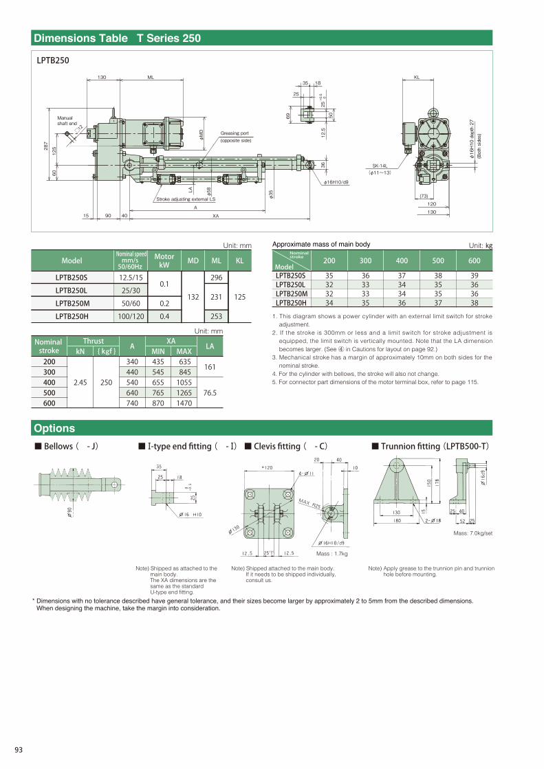
LPTB250SLPTB250LLPTB250MLPTB250H
200 300 400 500 600
35323234
36333335
37343436
38353537
39363638
XA
200300400500600
kN
2.45
{ kNf }
250
A
340440540640740
MIN435545655765870
MAX635845105512651470
LA
161
76.5
KLML
231 125
253
296
132
MD
0.2
0.4
0.112.5/15
25/30
50/60
100/120
LPTB250S
LPTB250L
LPTB250M
LPTB250H
LPTB250
287
60
125
15
ML
φMD
130
90
□12
(73)
120
130
KL
LA
φ58
φ35
50
18 35
25
69
25 +0.5 0
12.5
36
φ16H10/d9
40 XA
A
Manual shaft end
Greasing port (opposite side)
Stroke adjusting external LS
SK-14L (φ11~13)
Dimensions Table T Series 250
1. This diagram shows a power cylinder with an external limit switch for stroke adjustment.
2. If the stroke is 300mm or less and a limit switch for stroke adjustment is equipped, the limit switch is vertically mounted. Note that the LA dimension becomes larger. (See ④ in Cautions for layout on page 92.)
3. Mechanical stroke has a margin of approximately 10mm on both sides for the nominal stroke.
4. For the cylinder with bellows, the stroke will also not change.5. For connector part dimensions of the motor terminal box, refer to page 115.
Mass: 7.0kg/set
Mass : 1.7kg
(Both sides)
φ16H10 depth 27
Approximate mass of main body
MotorkW
Nominal speedmm/s50/60Hz
Model
Unit: mm Unit: ㎏
Model
Nominal stroke
Nominal stroke
Thrust Unit: mm
■ Ⅰ-type end fitting ( - Ⅰ) ■ Trunnion fitting (LPTB500-T)■ Clevis fitting ( - C)
Options
■ Bellows ( - J)
* Dimensions with no tolerance described have general tolerance, and their sizes become larger by approximately 2 to 5mm from the described dimensions. When designing the machine, take the margin into consideration.
Note) Apply grease to the trunnion pin and trunnion hole before mounting.
Note) Shipped as attached to the main body.The XA dimensions are the same as the standard U-type end fitting.
Note) Shipped attached to the main body.If it needs to be shipped individually, consult us.
93

LPTC250
(φ11~13) SK-14L
125
A
XA
φ16H10/d9
36
12.5
+0.5
0 25
69
25
35 18
50
2000L
101 φ35
φ58LA
KL
120
130
(73)
□12
90
130
φMD
ML
15
125
60
287
Dimensions Table T Series 250
LPTC250SLPTC250LLPTC250MLPTC250H
200 300 400 500 600
39363638
40373739
41383840
42393941
43404042
XA
200300400500600
kN
2.45
{ kNf }
250
A
340440540640740
MIN435545655765870
MAX635845105512651470
LA
161
76.5
KLML
231 125
253
296
132
MD
0.2
0.4
0.112.5/15
25/30
50/60
100/120
LPTC250S
LPTC250L
LPTC250M
LPTC250H 1. This diagram shows a power cylinder with an external limit switch for stroke adjustment.
2. If the stroke is 300mm or less and a limit switch for stroke adjustment is equipped, the limit switch is vertically mounted. Note that the LA dimension becomes larger. (See ④ in Cautions for layout on page 92.)
3. Mechanical stroke has a margin of approximately 10mm on both sides for the nominal stroke.
4. For the cylinder with bellows, the stroke will also not change.5. Use TC type model in brake individual turnoff.6. For connector part dimensions of the motor terminal box, refer to page 115.
Mass: 7.0kg/set
Mass : 1.7kg
0.75□X6C
Manual shaft end
Stroke adjusting external LS
Greasing port (opposite side)
(Both sides)
φ16H10 depth 27
Unit: mm
Nominal stroke
Thrust
Approximate mass of main body
MotorkW
Nominal speedmm/s50/60Hz
Model
Unit: mm Unit: ㎏
Model
Nominal stroke
■ Ⅰ-type end fitting ( - Ⅰ) ■ Trunnion fitting (LPTB500-T)■ Clevis fitting ( - C)
Options
■ Bellows ( - J)
Note) Apply grease to the trunnion pin and trunnion hole before mounting.
* Dimensions with no tolerance described have general tolerance, and their sizes become larger by approximately 2 to 5mm from the described dimensions. When designing the machine, take the margin into consideration.
Note) Shipped attached to the main body.If it needs to be shipped individually, consult us.
Note) Shipped as attached to the main body.The XA dimensions are the same as the standard U-type end fitting.
Pow
erC
ylin
der
Eco
ser
ies
Min
i ser
ies
Inq
uir
y F
orm
Mu
lti s
erie
sT
ser
ies
G s
erie
sF
ser
ies
94
* Dimensions with no tolerance described have general tolerance, and their sizes become larger by approximately 2 to 5mm from the described dimensions. When designing the machine, take the margin into consideration.
Note) Shipped as attached to the main body.The XA dimensions are the same as the standard U-type end fitting.
Note) Shipped attached to the main body.If it needs to be shipped individually, consult us.
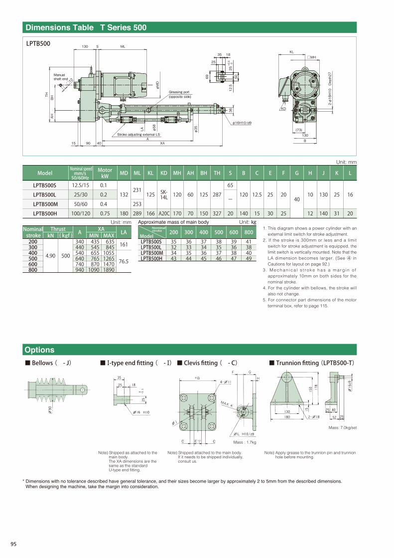
H J K L G B C E F S MH AH BH TH KL ML MD KD
LPTB500S LPTB500L LPTB500M LPTB500H
200 300 400 500 600
35 32 34 43
36 33 35 44
37 34 36 45
38 35 37 46
39 36 38 47
800
41 38 40 49
XA
200 300 400 500 600 800
kN
4.90
{ kNf }
500
A
340 440 540 640 740 940
MIN 435 545 655 765 870 1090
MAX 635 845 1055 1265 1470 1890
LA
161
76.5
1. This diagram shows a power cylinder with an external limit switch for stroke adjustment.
2. If the stroke is 300mm or less and a limit switch for stroke adjustment is equipped, the limit switch is vertically mounted. Note that the LA dimension becomes larger. (See ④ in Cautions for layout on page 92.)
3 . M e c h a n i c a l s t r o k e h a s a m a r g i n o f approximately 10mm on both sides for the nominal stroke.
4. For the cylinder with bellows, the stroke will also not change.
5. For connector part dimensions of the motor terminal box, refer to page 115.
LPTB500S
LPTB500L
LPTB500M
LPTB500H
10
12
130
140
25
31
16
20
40
20
120
140
12.5
15
25
30
20
25
65
- 120
170
60
70
125
150
287
327
231 125 SK- 14L
166 289
132
12.5/15
25/30
50/60
100/120
0.1
0.2
0.4 253
0.75 A20C 180
Mass: 7.0kg/set
Note) Apply grease to the trunnion pin and trunnion hole before mounting.
Mass : 1.7kg
■ Ⅰ-type end fitting ( - Ⅰ) ■ Trunnion fitting (LPTB500-T)■ Clevis fitting ( - C)
Options
■ Bellows ( - J)
Dimensions Table T Series 500
LPTB500 18 35
25
69
50
12.5
+0.5
0 25
ML S 130 AH
BH TH
40 15 90 LA
φ58
φ35
XA A
□12
φMD
φ16H10/d9
36
KL
(73)
B 130
KD
□MH
2-φ16H10 Depth27
Stroke adjusting external LS
Greasing port (opposite side)
Manual shaft end
MotorkW
Nominal speedmm/s50/60Hz
Model
Approximate mass of main body
Nominal stroke
Thrust Unit: mm
Unit: mm
Unit: ㎏
Model
Nominal stroke
95

Note) Shipped attached to the main body.If it needs to be shipped individually, consult us.
Note) Shipped as attached to the main body.The XA dimensions are the same as the standard U-type end fitting.
* Dimensions with no tolerance described have general tolerance, and their sizes become larger by approximately 2 to 5mm from the described dimensions. When designing the machine, take the margin into consideration.
H J K L G B C E F S MH AH BH TH KL ML MD KD
LPTC500S LPTC500L LPTC500M LPTC500H
200 300 400 500 600
39 36 38
40 37 39
41 38 40
42 39 41
43 40 42
800
45 42 44
47 48 49 50 51 53
XA
200 300 400 500 600 800
kN
4.90
{ kNf }
500
A
340 440 540 640 740 940
MIN 435 545 655 765 870 1090
MAX 635 845 1055 1265 1470 1890
LA
161
76.5
1. This diagram shows a power cylinder with an external limit switch for stroke adjustment.
2. If the stroke is 300mm or less and a limit switch for stroke adjustment is equipped, the limit switch is vertically mounted. Note that the LA dimension becomes larger. (See ④ in Cautions for layout on page 92.)
3 . M e c h a n i c a l s t r o k e h a s a m a r g i n o f approximately 10mm on both sides for the nominal stroke.
4. For the cylinder with bellows, the stroke will also not change.
5. Use TC type model in brake individual turnoff.6. For connector part dimensions of the motor
terminal box, refer to page 115.7. The terminal box lead-out direction in this
diagram is for the H speed.For the S, L, and M speeds, the direction is the same as the LPTC250 type.
LPTC500S
LPTC500L
LPTC500M
LPTC500H
10
12
130
140
25
31
16
20
40
20
120
140
12.5
15
25
30
20
25
65
- 120
170
60
70
125
150
287
327
231 125 SK- 14L
166 289
132
12.5/15
25/30
50/60
100/120
0.1
0.2
0.4 253
0.75 A20C 180
■ Ⅰ-type end fitting ( - Ⅰ) ■ Trunnion fitting (LPTB500-T)■ Clevis fitting ( - C)
Options
■ Bellows ( - J)
Dimensions Table T Series 500
Mass: 7.0kg/set
Note) Apply grease to the trunnion pin and trunnion hole before mounting.
Mass : 1.7kg
KL
(73)
B 130
KD
□MH
LPTC500
0.75□X6C 2000L
125 15
ML S 130
AH
BH TH
φMD
LA
φ35
XA A
φ58
φ16H10/d9
18 35
25
50
12.5
69
90
+0.5
0 25
□12
36
2-φ16H10 Depth27Manual
shaft end
Greasing port (opposite side)
MotorkW
Nominal speedmm/s50/60Hz
Model
Approximate mass of main body
Nominal stroke
Thrust Unit: mm Unit: ㎏
Unit: mm
Model
Nominal stroke
Pow
er C
ylin
der
Eco
ser
ies
Min
i ser
ies
Inq
uir
y F
orm
Mu
lti s
erie
sT
ser
ies
G s
erie
sF
ser
ies
96

KL ML
166
178
231
253
289
351
180
194
132 125
MD
0.2
0.4
0.75
1.5
12.5/15
25/30
50/60
100/120
LPTB1000S
LPTB1000L
LPTB1000M
LPTB1000H
MH
120
170
KD
A20C
SK- 14L
S
65
-
20
LPTB1000S LPTB1000L LPTB1000M LPTB1000H
200 300 400 500 600
42 40 46 50
44 42 48 52
45 43 49 53
47 45 51 55
48 46 52 56
XA kN
9.80
{ kNf }
1000
A MIN MAX
LA
161
76.5
800
51 49 55 59
1000
54 52 58 62
7.84 800
1. This diagram shows a power cylinder with an external limit switch for stroke adjustment.
2. If the stroke is 300mm or less and a limit switch for stroke adjustment is equipped, the limit switch is vertically mounted. Note that the LA dimension becomes larger. (See ④ in Cautions for layout on page 92.)
3. Mechanical stroke has a margin of approximately 10mm on both sides for the nominal stroke.
4. For the cylinder with bellows, the stroke will also not change.5. For connector part dimensions of the motor terminal box, refer to page 115.
* Dimensions with no tolerance described have general tolerance, and their sizes become larger by approximately 2 to 5mm from the described dimensions. When designing the machine, take the margin into consideration.
■ Ⅰ-type end fitting ( - Ⅰ) ■ Trunnion fitting (LPTB1000-T)■ Clevis fitting ( - C)
Options
■ Bellows ( - J)
200 300 400 500 600 800 1000
360 460 560 660 760 960 1160
465 575 685 795 900 1120 1340
665 875 1085 1295 1500 1920 2340
Mass: 7.0kg/set
Nominal stroke
Model
Approximate mass of main body Unit: ㎏
Unit: mm
Nominal speedmm/s50/60Hz
Model
Unit: mm
MotorkW
Nominal stroke
Thrust
Note) Apply grease to the trunnion pin and trunnion hole before mounting.
Mass : 2.6kg
Note) Shipped as attached to the main body.The XA dimensions are the same as the standard U-type end fitting.
Note) Shipped attached to the main body.If it needs to be shipped individually, consult us.
Dimensions Table T Series 1000
LPTB1000
90
φ40
φ70
LA
15
82
φ20H10/d9
40
60
45
30
20
XA A
50
+0.5
0 30
15
70
150 327
ML
φMD
116
S 130
□12
KD
(73)
140
150
KL
□MH
2-φ20H10 Depth32
Stroke adjusting external LS
Manual shaft end
Greasing port (opposite side)
97

KL ML
166
178
231
253
289
351
180
194
132 125
MD
0.2
0.4
0.75
1.5
12.5/15
25/30
50/60
100/120
LPTC1000S
LPTC1000L
LPTC1000M
LPTC1000H
MH
120
170
KD
A20C
SK- 14L
S
65
-
20
LPTC1000S LPTC1000L LPTC1000M LPTC1000H
200 300 400 500 600
48 46 52 56
50 48 54 58
51 49 55 59
53 51 57 61
54 52 58 62
XA kN
9.80
{ kNf }
1000
A MIN MAX
LA
161
76.5
800
57 55 61 65
1000
60 58 64 68
7.84 800
1. This diagram shows a power cylinder with an external limit switch for stroke adjustment.
2. If the stroke is 300mm or less and a limit switch for stroke adjustment is equipped, the limit switch is vertically mounted. Note that the LA dimension becomes larger. (See ④ in Cautions for layout on page 92.)
3. Mechanical stroke has a margin of approximately 10mm on both sides for the nominal stroke.
4. For the cylinder with bellows, the stroke will also not change.5. Use TC type model in brake individual turnoff.6. When the model of the TC type nominal stroke 1000mm is used, press and stop
cannot be carried out near the maximum stroke in terms of buckling strength. 7. For connector part dimensions of the motor terminal box, refer to page 115.
Nominal stroke
Model
Approximate mass of main body Unit: mm Unit: ㎏
Unit: mm
MotorkW
Nominal speedmm/s50/60Hz
Model
Nominal stroke
Thrust
* Dimensions with no tolerance described have general tolerance, and their sizes become larger by approximately 2 to 5mm from the described dimensions. When designing the machine, take the margin into consideration.
200 300 400 500 600 800 1000
360 460 560 660 760 960 1160
465 575 685 795 900 1120 1340
665 875 1085 1295 1500 1920 2340
Mass: 7.0kg/set
■ Ⅰ-type end fitting ( - Ⅰ) ■ Trunnion fitting (LPTB1000-T)■ Clevis fitting ( - C)
Options
■ Bellows ( - J)
Note) Apply grease to the trunnion pin and trunnion hole before mounting.
Mass : 2.6kg
Note) Shipped attached to the main body.If it needs to be shipped individually, consult us.
Note) Shipped as attached to the main body.The XA dimensions are the same as the standard U-type end fitting.
Dimensions Table T Series 1000
LPTC1000
145 90
LA
∅40
XA A
40
∅20H10/d9
45
30
20
82
15
60
+0.5
0 30
116
ML S 130
70
150 327
0.75□X6C 2000L 15
□12
∅MD
KD
KL
(73)
140
150
□MH
KD
KL
(73)
140
150
□MH
2-∅20H10 Depth32
Stroke adjusting external LS
Manual shaft end
Greasing port (opposite side)
Pow
er C
ylin
der
Eco
ser
ies
Min
i ser
ies
Inq
uir
y F
orm
Mu
lti s
erie
sT
ser
ies
G s
erie
sF
ser
ies
98
1. This diagram shows a power cylinder with an external limit switch for stroke adjustment.
2. If the stroke is 300mm or less and a limit switch for stroke adjustment is equipped, the limit switch is vertically mounted. Note that the LA dimension becomes larger. (See ④ in Cautions for layout on page 92.)
3. Mechanical stroke has a margin of approximately 10mm on both sides for the nominal stroke.
4. For the cylinder with bellows, the stroke will also not change.5. For connector part dimensions of the motor terminal box, refer to page 115.
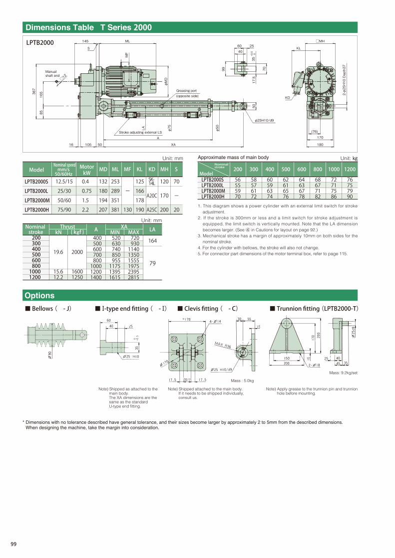
LPTB2000S LPTB2000L LPTB2000M LPTB2000H
200
56 55 59 70
300
58 57 61 72
400
60 59 63 74
500
62 61 65 76
600
64 63 67 78
800
68 67 71 82
1000
72 71 75 86
1200
76 75 79 90
132
180
194
207
MD
0.4
0.75
1.5
2.2
12.5/15
25/30
50/60
75/90
LPTB2000S
LPTB2000L
LPTB2000M
LPTB2000H
253
289
351
381
ML
-
130 A25C
MF
125 SK- 14L 166
178
190
KL
A20C
KD
120
200
170
70
20
-
MH S
XA
200 300 400 500 600 800 1000 1200
kN
19.6
{ kNf }
2000
A 400 500 600 700 800 1000 1200 1400
MIN 520 630 740 850 955 1175 1395 1615
MAX 720 930 1140 1350 1555 1975 2395 2815
LA
164
79
* Dimensions with no tolerance described have general tolerance, and their sizes become larger by approximately 2 to 5mm from the described dimensions. When designing the machine, take the margin into consideration.
Note) Shipped as attached to the main body.The XA dimensions are the same as the standard U-type end fitting.
Note) Shipped attached to the main body.If it needs to be shipped individually, consult us.
15.6 12.2
1600 1250
LPTB2000
Dimensions Table T Series 2000
■ Ⅰ-type end fitting ( - Ⅰ) ■ Trunnion fitting (LPTB2000-T)■ Clevis fitting ( - C)
Options
■ Bellows ( - J)
KD
367
85
165
16
MF
ML
φMD
S
105
145
170
180
(76)
KL
LA
φ75
φ50
40 60 25
99
50
17.5
70
φ25H10/d9
XA
A
50
+0.5
0 35
□MH
□12
Mass: 9.2kg/set
2-φ25H10 Dapth37
Manual shaft end
Stroke adjusting external LS
Greasing port (opposite side)
Approximate mass of main body
Thrust
Unit: mm Unit: ㎏
Unit: mm
ModelMotorkW
Nominal speedmm/s50/60Hz
ModelNominal stroke
Nominal stroke
Note) Apply grease to the trunnion pin and trunnion hole before mounting.
Mass : 5.0kg
99

1. This diagram shows a power cylinder with an external limit switch for stroke adjustment.
2. If the stroke is 300mm or less and a limit switch for stroke adjustment is equipped, the limit switch is vertically mounted. Note that the LA dimension becomes larger. (See ④ in Cautions for layout on page 92.)
3. Mechanical stroke has a margin of approximately 10mm on both sides for the nominal stroke.
4. For the cylinder with bellows, the stroke will also not change.5. Use TC type model in brake individual turnoff.6. When the model of the TC type nominal stroke 1000 or 1200mm is used, press
and stop cannot be carried out near the maximum stroke in terms of buckling strength.
7. For connector part dimensions of the motor terminal box, refer to page 115.
LPTC2000S LPTC2000L LPTC2000M LPTC2000H
200
64 63 67 78
300
66 65 69 80
400
68 67 71
500
70 69 73
600
72 71 75
800
76 75 79
1000
80 79 83
1200
84 83 87
82 84 86 90 94 98
132
180
194
207
MD
0.4
0.75
1.5
2.2
12.5/15
25/30
50/60
75/90
LPTC2000S
LPTC2000L
LPTC2000M
LPTC2000H
253
289
351
381
ML
-
130 A25C
MF
125 SK- 14L 166
178
190
KL
A20C
KD
120
200
170
70
20
-
MH S
XA
200 300 400 500 600 800 1000 1200
kN
19.6
{ kNf }
2000
A 400 500 600 700 800 1000 1200 1400
MIN 520 630 740 850 955 1175 1395 1615
MAX 720 930 1140 1350 1555 1975 2395 2815
LA
164
79
Note) Shipped attached to the main body.If it needs to be shipped individually, consult us.
Note) Shipped as attached to the main body.The XA dimensions are the same as the standard U-type end fitting.
* Dimensions with no tolerance described have general tolerance, and their sizes become larger by approximately 2 to 5mm from the described dimensions. When designing the machine, take the margin into consideration.
15.6 12.2
1600 1250
■ Ⅰ-type end fitting ( - Ⅰ) ■ Trunnion fitting (LPTB2000-T)■ Clevis fitting ( - C)
Options
■ Bellows ( - J)
LPTC2000
Dimensions Table T Series 2000
MF
ML
S
145
0.75□X6C 2000L
367
85
165
16
LA
105 110
φ75
φ50
165 XA
A
φ25H10/d9
50
40 60 25
99
70
17.5
KL
(76)
170
180
KD
φMD
+0.5
0 35
□MH
□12
Mass: 9.2kg/set
2-φ25H10 Depth37
Stroke adjusting external LS
Manual shaft end
Greasing port (opposite side)
Nominal stroke
Model
Approximate mass of main body Unit: mm Unit: ㎏
Unit: mm
MotorkW
Nominal speedmm/s50/60Hz
Model
Nominal stroke
Thrust
Note) Apply grease to the trunnion pin and trunnion hole before mounting.
Mass : 5.0kg
Pow
er C
ylin
der
Eco
ser
ies
Min
i ser
ies
Inq
uir
y F
orm
Mu
lti s
erie
sT
ser
ies
G s
erie
sF
ser
ies
100

1. This diagram shows a power cylinder with an external limit switch for stroke adjustment.
2. If the stroke is 300mm or less and a limit switch for stroke adjustment is equipped, the limit switch is vertically mounted. Note that the LA dimension becomes larger. (See ④ in Cautions for layout on page 92.)
3. Mechanical stroke has a margin of approximately 10mm on both sides for the nominal stroke.
4. For the cylinder with bellows, the stroke will also not change.5. For connector part dimensions of the motor terminal box, refer to page 115.
1500 1200 1000 800 600 500 400 300 200
LPTB4000S LPTB4000L LPTB4000M LPTB4000H
133 143 162
122 132 151
115 125 144
108 118 137
101 111 130
136 125 118 111 104
108
101
127 104 123
101 120
87 97
90 94 97 91 94 98
116
180
194
207
229
0.75
1.5
2.2
3.7
9/11
25/30
35/42
60/72
LPTB4000S
LPTB4000L
LPTB4000M
LPTB4000H
289
351
381
414
-
130
141 A25C
166
178
190
201
A20C
200
170 90
-
20
MD ML MF KL KD MH S
XA kN { kNf } A MIN MAX LA
* Dimensions with no tolerance described have general tolerance, and their sizes become larger by approximately 2 to 5mm from the described dimensions. When designing the machine, take the margin into consideration.
200 300 400 500 600 800 1000 1200 1500
440 550 650 750 850 1050 1250 1450 1750
585 695 805 910 1020 1235 1450 1670 1995
785 995 1205 1410 1620 2035 2450 2870 3495
182
97.5 39.2 4000
33.3 3400
LPTB4000
Dimensions Table T Series 4000
446
100
195
S
170
∅MD
MF
ML
18 130 50
∅95
LA
A
XA
∅70
∅32H10/d9
70
20
35 75
115
50
80
40 +0.5
0
KD
200
220
(85)
KL
□MH
2-∅32H10 Depth45
□12
Mass: 16.4kg/set
Manual shaft end
Stroke adjusting external LS
Greasing port (opposite side)
Nominal stroke
Model
Approximate mass of main body Unit: mm Unit: ㎏
Unit: mm
MotorkW
Nominal speedmm/s50/60Hz
Model
Nominal stroke
Thrust
■ Ⅰ-type end fitting ( - Ⅰ) ■ Trunnion fitting (LPTB4000-T)■ Clevis fitting ( - C)
Options
■ Bellows ( - J)
Note) Apply grease to the trunnion pin and trunnion hole before mounting.
Mass : 9.5kg
Note) Shipped as attached to the main body.The XA dimensions are the same as the standard U-type end fitting.
Note) Shipped attached to the main body.If it needs to be shipped individually, consult us.
101

1. This diagram shows a power cylinder with an external limit switch for stroke adjustment.
2. If the stroke is 300mm or less and a limit switch for stroke adjustment is equipped, the limit switch is vertically mounted. Note that the LA dimension becomes larger. (See ④ in Cautions for layout on page 92.)
3. Mechanical stroke has a margin of approximately 10mm on both sides for the nominal stroke.
4. For the cylinder with bellows, the stroke will also not change.5. Use TC type model in brake individual turnoff.6. When the model of the TC type nominal stroke 1500mm is used, press and stop
cannot be carried out near the maximum stroke in terms of buckling strength. 7. For connector part dimensions of the motor terminal box, refer to page 115.
1500 1200 1000 800 600 500 400 300 200
LPTC4000S LPTC4000L LPTC4000M LPTC4000H
151 148 158 177
140 137 147 166
133 130 140 159
126 123 133 152
119 116 126 145
116 113 123 142
112 109 119 138
109 106 116 135
105 102 112 131
180
194
207
229
0.75
1.5
2.2
3.7
9/11
25/30
35/42
60/72
LPTC4000S
LPTC4000L
LPTC4000M
LPTC4000H
289
351
381
414
-
130
141 A25C
166
178
190
201
A20C
200
170 90
-
20
MD ML MF KL KD MH S
XA kN { kNf } A MIN MAX LA
* Dimensions with no tolerance described have general tolerance, and their sizes become larger by approximately 2 to 5mm from the described dimensions. When designing the machine, take the margin into consideration.
200 300 400 500 600 800 1000 1200 1500
440 550 650 750 850 1050 1250 1450 1750
585 695 805 910 1020 1235 1450 1670 1995
785 995 1205 1410 1620 2035 2450 2870 3495
182
97.5 39.2 4000
33.3 3400
■ Ⅰ-type end fitting ( - Ⅰ) ■ Trunnion fitting (LPTB4000-T)■ Clevis fitting ( - C)
Options
■ Bellows ( - J)
LPTC4000
Dimensions Table T Series 4000
446
100
195
170
MF
ML
S
∅MD
18 130 195
127 LA ∅95
∅70
A
XA
0.75□X6C 2000L
20
80
35 75
115
50
40 +0.5
0 70
KD
∅32H10/d9
(85)
200
220
2-∅32H10 Depth45
□MH
KL
□12
Mass: 16.4kg/set
Stroke adjusting external LS
Manual shaft end
Greasing port (opposite side)
Approximate mass of main body Unit: mm Unit: ㎏
Unit: mm
MotorkW
Nominal speedmm/s50/60Hz
Model
Nominal stroke
Thrust
Nominal stroke
Model
Note) Apply grease to the trunnion pin and trunnion hole before mounting.
Mass : 9.5kg
Note) Shipped attached to the main body.If it needs to be shipped individually, consult us.
Note) Shipped as attached to the main body.The XA dimensions are the same as the standard U-type end fitting.
Pow
er C
ylin
der
Eco
ser
ies
Min
i ser
ies
Inq
uir
y F
orm
Mu
lti s
erie
sT
ser
ies
G s
erie
sF
ser
ies
102

XA kN { kNf }
A MIN MAX
500
1000
1500
58.8 6000
855
1355
1955
1010
1560
2210
1510
2560
3710
180
194
207
229
0.75
1.5
2.2
3.7
6.3/7.6
17.5/21
25/30
42/50
LPTB6000S LPTC6000S LPTB6000L LPTC6000L LPTB6000M LPTC6000M LPTB6000H LPTC6000H
289
351
381
414
-
-
130
141 A25C
166
178
190
201
A20C
200
170 90
-
20
MD ML MF KL KD MH S 500 1000 1500
LPTB6000S LPTC6000S LPTB6000L LPTC6000L LPTB6000M LPTC6000M LPTB6000H LPTC6000H
143 165 151 173 157 179 172 194
168 190 176 198 182 204 197 219
193 215 201 223 207 229 222 244
1. This diagram shows a power cylinder with an external limit switch for stroke adjustment.
2. Mechanical stroke has a margin of approximately 10mm on both sides for the nominal stroke.
3. For the cylinder with bellows, the stroke will also not change.4. Use TC type model in brake individual turnoff.5. When the model of the TC type nominal stroke 1500mm is used, press and stop
cannot be carried out near the maximum stroke in terms of buckling strength.6. For connector part dimensions of the motor terminal box, refer to page 115.
Dimensions Table T Series 6000
LPTB6000
LPTC6000
518
230
120
175
S
ML
MF
φMD
205 22 XA
A
φ80
φ115 φ40H10
φ80
20 65 40
240
260
2-φ40H10-Depth55
Greasing port
Grease discharge port
Stroke adjusting external LS
Manual shaft end
KD
KL
□MH
45 0 -1.0
□17
518
230
MF
φMD
120
□MH
KL
KD
240
260
2-φ40H10-Depth55
φ40H10
φ80
φ115
φ80
40 65 20
XA
A
300 22
175
S
ML
□17
0.75□×6C 2000L
45 0 -1.0
Mass: 39.0kg/set
60
155
Manual shaft end
Grease discharge port
Stroke adjusting external LS
Greasing port
Approximate mass of main body Unit: mm Unit: ㎏
Unit: mm
MotorkW
Nominal speedmm/s50/60Hz
ModelNominal stroke
Model
Nominal stroke
Thrust
Options
■ Bellows ( - J) ■ Trunnion fitting (LPTB6000-T)■ Clevis fitting ( - C)
* Dimensions with no tolerance described have general tolerance, and their sizes become larger by approximately 2 to 5mm from the described dimensions. When designing the machine, take the margin into consideration.
Note) Apply grease to the trunnion pin and trunnion hole before mounting.
Mass : 16.5kg
Note) Shipped attached to the main body.If it needs to be shipped individually, consult us.
103

1. This diagram shows a power cylinder with an external limit switch for stroke adjustment.
2. Mechanical stroke has a margin of approximately 10mm on both sides for the nominal stroke.
3. For the cylinder with bellows, the stroke will also not change.4. Use TC type model in brake individual turnoff.5. When the model of the TC type nominal stroke 1500mm is used, press and stop
cannot be carried out near the maximum stroke in terms of buckling strength.6. For connector part dimensions of the motor terminal box, refer to page 115.
XA kN { kNf }
A MIN MAX
500
1000
1500
78.4 8000 1400
1900
1615
900 1065
2165
1565
2615
3665
MD ML MF KL KD MH S 500 1000 1500
LPTB8000S LPTC8000S LPTB8000L LPTC8000L LPTB8000M LPTC8000M LPTB8000H LPTC8000H
224 254 212 242 230 260 241 271
254 284 242 272 260 290 271 301
284 314 272 302 290 320 301 331
Dimensions Table T Series 8000
LPTB8000
LPTC8000
* Dimensions with no tolerance described have general tolerance, and their sizes become larger by approximately 2 to 5mm from the described dimensions. When designing the machine, take the margin into consideration.
Options
■ Bellows ( - J) ■ Trunnion fitting (LPTB8000-T)■ Clevis fitting ( - C)
Note) Apply grease to the trunnion pin and trunnion hole before mounting.
Mass : 27.0kg
194
207
229
265
1.5
2.2
3.7
5.5
10/12
20/24
30/36
43/52
LPTB8000S LPTC8000S LPTB8000L LPTC8000L LPTB8000M LPTC8000M LPTB8000H LPTC8000H
351
381
414
403
-
130
141
156
A25C
178
190
201
245
A20C
250
170
200
137
-
-
25
□MH
KL
KD
2-φ45H10-Depth60 φ95
φ45H10
300
310
45 70 25
φMD
φ130
φ95
MF
ML S
195
280
150
578
29 240
A
XA
50 0 -1.0
□17
578
280
MF
φMD
φ130
φ95
φ95
2-φ45H10-Depth60
150
195 ML S
29 340
A
XA
φ45H10
KD
70 45
KL
□MH
300
310
□17
0.75□×6C 2000L
50 0 -1.0
25
Mass: 70.6kg/set
65
165
Greasing port (opposite side)
Stroke adjusting external LS
Manual shaft end
Manual shaft end
Stroke adjusting external LS
Greasing port (opposite side)
Approximate mass of main body Unit: ㎏
Unit: mm
Unit: mm
MotorkW
Nominal speedmm/s50/60Hz
ModelNominal strokeModel
Nominal stroke
Thrust
Note) Shipped attached to the main body.If it needs to be shipped individually, consult us.
Pow
er C
ylin
der
Eco
ser
ies
Min
i ser
ies
Inq
uir
y F
orm
Mu
lti s
erie
sT
ser
ies
G s
erie
sF
ser
ies
104

1. This diagram shows a power cylinder with an external limit switch for stroke adjustment.
2. Mechanical stroke has a margin of approximately 10mm on both sides for the nominal stroke.
3. For the cylinder with bellows, the stroke will also not change.4. Use TC type model in brake individual turnoff.5. When the model of the TC type nominal stroke 2000mm is used, press and stop
cannot be carried out near the maximum stroke in terms of buckling strength.6. For connector part dimensions of the motor terminal box, refer to page 115.
LPTB12000L LPTC12000L LPTB12000M LPTC12000M LPTB12000H LPTC12000H
500 1000 1500
270 309 285 324 295 334
312 351 327 366 337 376
354 393 369 408 379 418
2000
396 435 411 450 421 460
XA
500
1000
1500
2000
kN
117 12000
A
950
1450
1950
2450
MIN 1135
1685
2235
2785
MAX 1635
2685
3735
4785
207
229
265
MD
2.2
3.7
5.5
10/12
18/22
30/36
LPTB12000L LPTC12000L LPTB12000M LPTC12000M LPTB12000H LPTC12000H
381
414
403
ML
130
141
156
MF
190
201
245
KL
A25C
200
250
250
KD
145
145
25
MH S
φ180
Dimensions Table T Series 12000
LPTB12000
LPTC12000
* Dimensions with no tolerance described have general tolerance, and their sizes become larger by approximately 2 to 5mm from the described dimensions. When designing the machine, take the margin into consideration.
Options
■ Bellows ( - J) ■ Clevis fitting ( - C) ■ Trunnion fitting (LPTB12000-T)
Note) Apply grease to the trunnion pin and trunnion hole before mounting.
Mass : 33.0kg
578 280
φMD
MF
150
25 250
A
XA
195 ML S
25 90 55 KL
□MH
300
KD
φ50H10
350
φ110
φ160
φ110
2-φ50H10-Depth70
□17
65 0 -1.0
□17
0.75□×6C 2000L
195 S
ML
25 90 55
KD
KL □MH
300
350
φ50H10
XA A
350 25
578
280
150
MF
φMD
φ160
φ110
φ110
2-φ50H10-Depth70
65 0 -1.0
Mass: 84.4kg/set
75
175
{ kNf }
Manual shaft end
Greasing port (opposite side)
Stroke adjusting external LS
Manual shaft end
Stroke adjusting external LS
Greasing port (opposite side)
Approximate mass of main body Unit: mm Unit: ㎏
Unit: mm
MotorkW
Nominal speedmm/s50/60Hz
ModelNominal stroke
Model
Nominal stroke
Thrust
Note) Shipped attached to the main body.If it needs to be shipped individually, consult us.
105

1. This diagram shows a power cylinder with an external limit switch for stroke adjustment.
2. Mechanical stroke has a margin of approximately 10mm on both sides for the nominal stroke.
3. For the cylinder with bellows, the stroke will also not change.4. Use TC type model in brake individual turnoff.5. When the model of the TC type nominal stroke 2000mm is used, press and stop
cannot be carried out near the maximum stroke in terms of buckling strength.6. For connector part dimensions of the motor terminal box, refer to page 115.
XA
500
1000
1500
2000
kN
156 16000
A
1060
1560
2060
2560
MIN 1260
1810
2360
2910
MAX 1760
2810
3860
4910
229
265
265
MD
3.7
5.5
7.5
14.5/17.5
20/24
31/37
LPTB16000L LPTC16000L LPTB16000M LPTC16000M LPTB16000H LPTC16000H
414
403
441
ML
141
156
156
MF KL
250
KD
145
170
170
MH S
LPTB16000L LPTC16000L LPTB16000M LPTC16000M LPTB16000H LPTC16000H
500 1000 1500
469 518 480 529 490 539
525 574 536 585 546 595
581 630 592 641 602 651
2000
637 686 648 697 658 707
201
245
245
A25C
Dimensions Table T Series 16000
LPTB16000
LPTC16000
225 ML S
30 100 65
KD
KL □MH
340
400
φ63H10
XA
A
310 38
□24
659
329
170
MF
φMD
φ180
φ130
φ130
2-φ63H10-Depth75
80 0 -1.0
225 S ML
38 400
A
XA
φ63H10
30 100 65
KD
KL
□MH
340
400
□24
0.75□×6C 2000L
659
329
MF
φMD
φ180
φ130
φ130
2-φ63H10-Depth75
170
80 0 -1.0
Mass: 124.6kg/set
90
180
{ kNf }
Stroke adjusting external LS
Greasing port (Manual side)
Manual shaft end
Manual shaft end
Stroke adjusting external LS
Greasing port (Manual side)
Approximate mass of main body Unit: mm Unit: ㎏
Unit: mm
Nominal strokeModel
MotorkW
Nominal speedmm/s50/60Hz
Model
Nominal stroke
Thrust
* Dimensions with no tolerance described have general tolerance, and their sizes become larger by approximately 2 to 5mm from the described dimensions. When designing the machine, take the margin into consideration.
Options
■ Bellows ( - J) ■ Trunnion fitting (LPTB16000-T)■ Clevis fitting ( - C)
Note) Apply grease to the trunnion pin and trunnion hole before mounting.
Mass : 54.0kg
Note) Shipped attached to the main body.If it needs to be shipped individually, consult us.
Pow
er C
ylin
der
Eco
ser
ies
Min
i ser
ies
Inq
uir
y F
orm
Mu
lti s
erie
sT
ser
ies
G s
erie
sF
ser
ies
106

Dimensions Table T Series 32000
LPTB32000
LPTC32000
1. This diagram shows a power cylinder with an external limit switch for stroke
adjustment.
2. Mechanical stroke has a margin of approximately 10mm on both sides for the
nominal stroke.
3. For the cylinder with bellows, the stroke will also not change.
4. For connector part dimensions of the motor terminal box, refer to page 115.
313 32000
265
265
324
MD
5.5
7.5
11
10/12
15/18
20/24
LPTB32000L LPTC32000L LPTB32000M LPTC32000M LPTB32000H LPTC32000H
403
441
519
ML KL KD
245
245
263
A25C
A25C
A30B
XA
500
1000
1500
2000
kN { kNf }
A
1315
1815
2315
2815
MIN 1575
2125
2675
3225
MAX 2075
3125
4175
5225
LPTB32000L LPTC32000L LPTB32000M LPTC32000M LPTB32000H LPTC32000H
500 1000 1500
1215 1305 1225 1315 1294 1384
1313 1403 1323 1413 1392 1482
1411 1501 1421 1511 1490 1580
2000
1509 1599 1519 1609 1588 1678
140 90
125 0 -2.0
86 190 ML
35
(34) 285 285 A
570 XA
φ90H10
140 90
Thrust detecting port
Manual shaft end
□27
Grease discharge port
φMD
φ240
φ180
125 0 -2.0
Mass: 149.2kg/set
(273)
540 520
2-∅90H10 DEPTH110
2-M30
KD
KL
50
φ180
35
φ180
86 190
1133
175
590
285
415
A
Grease discharge port Grease discharge portφ
240
φ180
130
Grease port (Manual side)
(34)
ML
φMD
260
XA
φ90H10
1133
175
590
260
(273)
540 520
2-∅90H10 DEPTH110
2-M30
KD
KL
Stroke adjusting external LS
50
Grease port (Manual side)
Stroke adjusting external LS
Manual shaft end
□27
Approximate mass of main body Unit: mm Unit: ㎏
Unit: mm
MotorkW
Nominal speedmm/sModel
Nominal stroke
Thrust Nominal strokeModel
Options
■ Bellows ( - J) ■ Clevis fitting ( - C) ■ Trunnion fitting (LPTB32000-T)
* Dimensions with no tolerance described have general tolerance, and their sizes become larger by approximately 2 to 5mm from the described dimensions. When designing the machine, take the margin into consideration.
Note) Apply grease to the trunnion pin and trunnion hole before mounting.
Mass : 185.0kg
Note) Shipped attached to the main body.If it needs to be shipped individually, consult us.
107
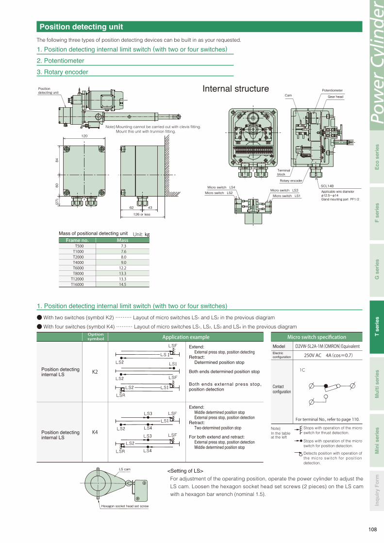
Position detecting unit
The following three types of position detecting devices can be built in as your requested.
120
84
(27)
126 or less
Note) Mounting cannot be carried out with clevis fitting.Mount this unit with trunnion fitting.
Position detecting unit
60
43 62
Internal structure
T500 T1000 T2000 T4000 T6000 T8000 T12000 T16000
7.3 7.6 8.0 9.0 12.2 13.3 13.3 14.5
Frame no. MassMass of positional detecting unit
ModelElectric configuration
Micro switch specification
Position detecting internal LS
Position detecting internal LS
● With two switches (symbol K2) ……… Layout of micro switches LS1 and LS2 in the previous diagram
● With four switches (symbol K4) ……… Layout of micro switches LS1, LS2, LS3 and LS4 in the previous diagram
<Setting of LS>
Contact configuration
D2VW-5L2A-1M(OMRON)Equivalent
250V AC 4A(cos=0.7)
For terminal No., refer to page 110.
Optionsymbol Application example
K2
K4Note) In the table at the left
1. Position detecting internal limit switch (with two or four switches)
For adjustment of the operating position, operate the power cylinder to adjust the
LS cam. Loosen the hexagon socket head set screws (2 pieces) on the LS cam
with a hexagon bar wrench (nominal 1.5).
Stops with operation of the micro switch for thrust detection.
Stops with operation of the micro switch for position detection.
Extend:External press stop, position detecting
Retract:Determined position stop
Extend:Middle determined position stopExternal press stop, position detection
Retract:Two-determined position stop
For both extend and retract:External press stop, position detectionMiddle determined position stop
Both ends determined position stop
Both ends external press stop, position detection
Detects position with operation of the micro switch for posit ion detection.
Unit: ㎏
1. Position detecting internal limit switch (with two or four switches)
2. Potentiometer
3. Rotary encoder
Rotary encoder
Terminal block
SCL14B
Applicable wire diameterφ12.5~φ14Gland mounting part PF1/2
Micro switch LS4
Micro switch LS2Micro switch LS3
Micro switch LS1
Potentiometer Cam Gear head
Hexagon socket head set screw
LS cam
Pow
er C
ylin
der
Eco
ser
ies
Min
i ser
ies
Inq
uir
y F
orm
Mu
lti s
erie
sT
ser
ies
G s
erie
sF
ser
ies
108

Position detecting unit2. Potentiometer
This is a variable resistor to output electric signals depending on the stroke amount of the
cylinder. Use this unit in combination with a printed board and a stroke indication meter.
Resistance values according to the model have been adjusted before shipment.
Separately request preset values according to the model as they are described in the
position detecting unit specification drawing. Pay strict attention to handling because
correspondence between the stroke position and the resistance value will deviate by
rotating the rod of the power cylinder.
Potentiometer specifications
Model
ManufacturerTotal resistance value
Rated powerDielectric strength
Effective electric degreeEffective mechanical degree
Connection
CP-30 or equivalentSAKAE TSUSHIN KOGYO CO., LTD.
1kΩ0.75W
1000V AC 1min.355°±5°360°endless
Connected to terminal block in position detecting unitP1 P3 P2
Cylinder rod retract Cylinder rod extend
3. Rotary encoder
Figures in parentheses indicate terminal No.
Output connection
Case0V+5V to 24VSignal ZSignal 2Signal 1
(9) (10) (11) (12) (13) (14)
Output circuitOutput waveform
a. b. c. d = T/4 ± T/8 T/2 ≦ e ≦ 3T/2
Signal 1(A-phase output)
Signal 2(B-phase output)
Signal Z(Z-phase output)
When extendingTa b c d
Maximum lead-in current 30mA (max)
e
H
H
H
L
L
L
+
out
-
Rotary encoder specificationsTS5305N251
Tamagawa Seiki Co., Ltd.600P/R
90° phase difference two-phase square wave + home position output̶
1V or less5~24V DC
HL
Power supply
Model
Manufacturer
Output pulse number
Output waveform
Output voltageNote 1)
Note 1)
①②③
④⑤⑥
109
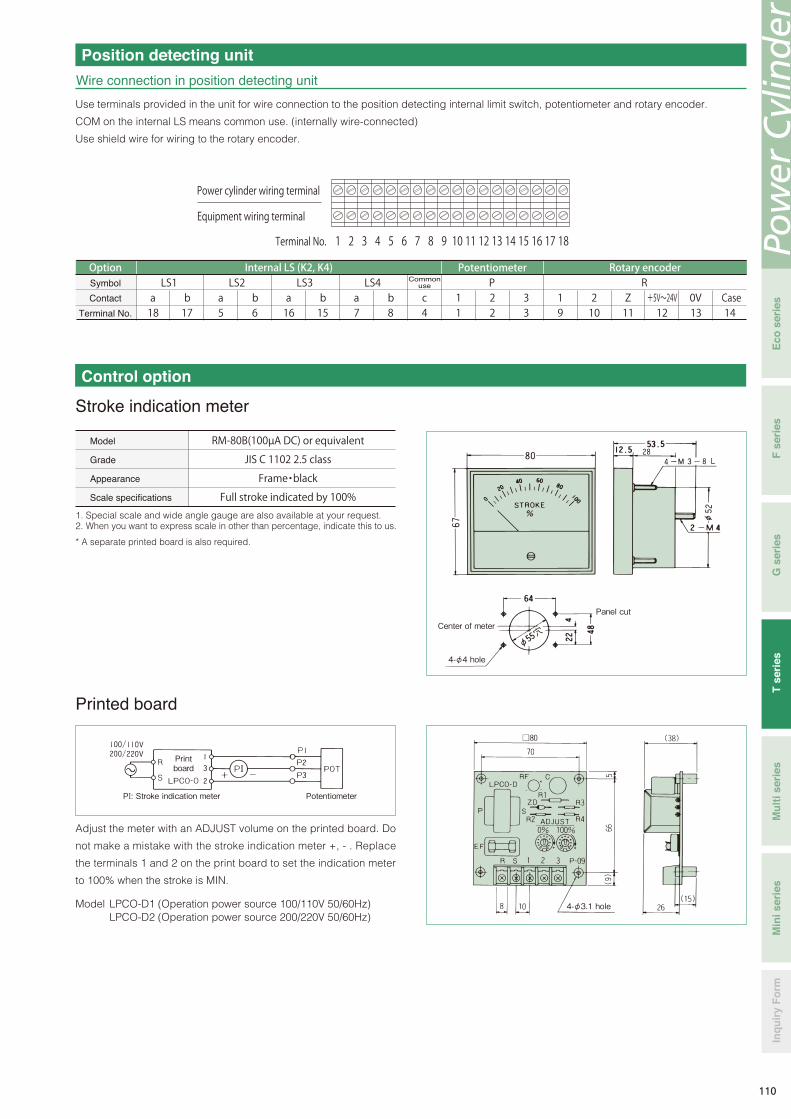
Position detecting unit
Wire connection in position detecting unit
Use terminals provided in the unit for wire connection to the position detecting internal limit switch, potentiometer and rotary encoder.
COM on the internal LS means common use. (internally wire-connected)
Use shield wire for wiring to the rotary encoder.
1 2 3 4 5 6 7 8 9 10 11 12 13 14 15 16 17 18
LS1 a 18
b 17
c 4
P R LS2 a 5
b 6
LS3 a 16
b 15
LS4 a 7
b 8
1 1
2 2
3 3
1 9
2 10
Z 11
+5V~24V12
0V 13 14
Printed board
Equipment wiring terminal
Power cylinder wiring terminal
Terminal No.
Internal LS (K2, K4)Common
use
Potentiometer Rotary encoder
Case
OptionSymbol
Contact
Terminal No.
Control option
Stroke indication meter
Model
Grade
Appearance
Scale specifications
RM-80B(100µA DC) or equivalent
JIS C 1102 2.5 class
Frame・black
Full stroke indicated by 100%
Center of meter
4-φ4 hole
Panel cut
Printboard
PI: Stroke indication meter Potentiometer
4-φ3.1 hole
Pow
er C
ylin
der
Eco
ser
ies
Min
i ser
ies
Inq
uir
y F
orm
Mu
lti s
erie
sT
ser
ies
G s
erie
sF
ser
ies
110

Wire connection is the same as that for the
st roke indicat ion meter , however, i t is
necessary to separately feed power to the
meter relay. Supply power from the operating
power supply. It is easy to connect the b
contact as an output contact to the b contact
for the stroke adjusting LS in series.
100 0
LOW
CONTACT RATING (RESISTIVE) 3A 250V AC , 3A 30V DC HIGH
±
M (-)
(+)
c
b
a c
b
a
101 100
40 40
32
32
83
15 4-M3
%
Control option
Meter relayUsed for simple adjustment of stroke on the operation panel.
Note) For using 4 – 20mA output, designate as “for 4 – 20mA output.”
* A separate printed board is also required.
Iron panel installation is standard. Separately
indicate to us when installing an aluminum panel.
Model number
Class
Appearance
Scale
Power source
Input
Output contact
configuration
Contact capacity
Meter relay specifications
( )
NRC-100HL (TSURUGA) or equivalent product
JIS C 1102 2.5 class
Frame・Black
Full stroke indicated by 100%
100/100V AC, 200/220V AC 50/60Hz
100μA DC maximum
1C for both HIGH, LOW sides(refer to the following Fig.)
250V AC 3A(cosφ=1)
(Described specifications and dimensions may be subject to change due to circumstances.)
15 or less
The main body of the power cylinder is provided with a potentiometer.The phase of a stroke deviates if the rod is rotated before installation. Therefore, cylinders with a stroke adjusting limit switch are recommended.Pre-set minimum and maximum strokes to be used with the stroke adjusting limit switch, then use the meter relay.
<Print board>
This is the same as the print board for the stroke indication meter.
<Relay operation> (In the case of b contact)
Measuring needle
Lower limit set index (L) Upper limit set index (H)
L side relay operation
H side relay operation
Shock relay
Our highly reliable shock relay is recommended as an electric safety device for the power cylinder of the TB type.
For details, refer to the “TSUBAKI E&M electric overload protection devices shock monitor shock relay catalogue.”
111

Stroke control for power cylinderThere are various methods of positioning control for the power
cylinder. Positioning accuracy greatly varies depending on the
speed of the power cylinder, the size of the load, the size of a load
inertia, the operating direction (vertical, horizontal) and the wire
connection method for the brake. Control methods may be limited
depending on the operating condition. As such, what methods
there are will be conceptually described here.
Limit switch method
Method with rotary encoder (RE)
Method with potentiometer
① With stroke adjusting limit switch……Positioning of stroke upper
and lower limit
② With position detecting limit switch……Intermediate positioning
Accuracy generally increases with lower cylinder speed.
③ Press (pull) stop (Thrust detecting limit switch for T series TC
type is used.)
This is a method that stoppers are mechanically provided on
both ends of a stroke used for equipment driven by the power
cylinder, and press, pull stop are carried out, and then a thrust
detecting limit switch for the power cylinder is used. The stroke
is mechanically regulated by the stoppers, therefore, accurate
positioning is possible.
This method is convenient when you want to change the stroke of
the power cylinder on the control side. Accuracy generally
increases as the cylinder speed decreases. For the power cylinder
body, the method wi th a stroke adjust ing l imi t swi tch is
recommended to prevent stroke over.
This method controls stroke by a programmable controller (PC).
Use the PC with a counter. Use a limit switch to detect home
position. (For the power cylinder body, the method with a stroke
adjusting limit switch is recommended.)
① Direct control method
With this method, when OFF signals for the motor and the brake
are not simultaneously outputted from the PC, and OFF signal for
the motor is outputted ear l ier , the cyl inder coasts whi le
decelerating. Highly accurate positioning is possible because the
power cylinder operates at a low speed such as output of an
operation signal for the brake just before the stop position.
② Motor speed control method
Note that, when a heavy object is moved up or down, or a load with
a large inertia is operated, it may not be sufficiently slowed down
by any method.
B: Brake (Individual turnoff)M: MotorRE: Rotary encoderLS: Stroke adjusting external limit switch
Electromagneticcontactor
Electromagneticswitch
PC High speed counterStroke setter
Power cylinder
Home position detection
Control with meter relay
B: Brake (Individual turnoff)M: MotorP: Potentiometer
Extend,retract button
Electromagneticcontactor
Electromagneticswitch
Meter relay
Transducer
Power cylinder
B: Brake (Individual turnoff)M: MotorRE: Rotary encoderLS: Stroke adjusting limit switch
Electromagneticcontactor
InverterPC High speed counterStroke setter
Power cylinder
Home position detection
Pow
er C
ylin
der
Eco
ser
ies
Min
i ser
ies
Inq
uir
y F
orm
Mu
lti s
erie
sT
ser
ies
G s
erie
sF
ser
ies
112

Wire connection
Wire connection for brake motor (Motor with DC brake)
0.1~0.4kW
0.1~0.4kW
0.75~3.7kW
LPTB LPTC32000
LPTB LPTC250~
LPTB LPTC16000
0.75~3.7kW
In the case of brake internal wiring
W B2
U
B1
V M B R S T
200V class
W B2
U
B1
V M B R S T
W B2
U
B1
V
R S T
400V class
M B
W B2
U
B1
V M B R S T
W B2
U
B1
V M B R S T
380~460V AC
W B2
U
B1
V M B R S T
W B2
U
B1
V M B R S T
200~220V AC200~220V AC
200~230V AC
R
S
T
M B
* Crimp contact bolt: M4
Power module Power module
From intermediate tap
From intermediate tap
Power side
Power side
For 5.5kW or higher,
use brake external wiring.
Power module
Common to 200/400V
Power side
In the case of brake external wiring
200V class
Power module
400V class
Power module
From intermediate tap
From intermediate tap
Power side
Power side
200V class
Power module
400V class
Power module
Power side
Power side
5.5kW or more
Rod operatingdirection
(In the case of connection on upper surface) Rod extend Rod retract
Common to 200/400V
Power side
Power module
85 113

W B2
U
B1
V M B R
200~220V AC
200~230V AC 380~460V AC
200~220V AC
S T W
B2
U
B1
V M B R S T
W B2
U
B1
V M B R S T W
B2
U
B1
V M B R S T
R
S
T
M B
Wire connection
◎ Wire connection method when inverter is used or brake is used in individual turnoff
・ If the motor is operated by the inverter, it is necessary to individually turn off the brake. When individually turning off the brake, as shown in the following diagram, remove the short piece, and do not connect wire to the brake power module from the inverter output, apply a normal power voltage. Separately provide a power supply shown in the following diagram and apply power to the brake power module. If separate power cannot be provided, decrease the voltage by a transformer. Use a transformer whose the capacity is more than necessary, and check that there is no voltage drop. And if the motor voltage of 0.1 to 0.4kW is 400V class, also remove the wire from the motor intermediate tap and insulate it.
・ If the motor voltage of 0.4kW or less is 400V class, remove the wire from the motor intermediate tap and insulate it, and separately provide a power supply of 200V to 220V and apply power to the brake power module. If there is no power source of 200V to 220V, decrease the voltage to 200V to 220V by a transformer. The capacity of the transformer shall be 90VA or more, and check that there is no voltage drop.Use an electromagnetic contactor for the brake of 200V class with a rated load of 250V AC, 7A or more. For the 400V class, use an electromagnetic contactor with a contact voltage of 400 to 440V AC, an induction load of 1A or more (e.g. electromagnetic contactor for AC motor 2.2kW). The power module includes a surge absorbing protection element. Add a protection element for the contact in each part if necessary.
・Do not put a relay contact on the output side of the standard power module (between the power module and brake coil). When carrying out [DC individual turnoff wiring] in which the relay contact is put into the position, contact us beforehand.
DC brake
Power module
0.1~0.4kW200V class
Inverter
From intermediate tap
From intermediate tap
Power module
0.1~0.4kW400V class
Make sure to insulate.
Make sure to insulate.
Inverter
0.75~3.7kW200V class
Power module
0.75~3.7kW400V class
Power module
Inverter Inverter
5.5kW or moreCommon to 200/400V
Inverter
Power module
Power side
Pow
er C
ylin
der
Eco
ser
ies
Min
i ser
ies
Inq
uir
y F
orm
Mu
lti s
erie
sT
ser
ies
G s
erie
sF
ser
ies
86 114

0.1kW~0.4kW
0.75kW~1.5kW
2.2kW~7.5kW
11kW
A20C
A25C
A30B
φ14~φ15
φ19~φ20
φ23~φ24
PF 3/4
PF 1
PF 1・1/4
φ28
φ35
φ42
SK-14L φ11~φ13 PF 1/2 -
Limit switch specifications
Stroke adjusting external LS
Limit switch type
Electric capacity
Contact configuration
Connector (Applicable cable outer diameter) SCS-10B(φ8.5~φ10.5)PF1/2 SCL-14A(φ10.5~φ12.5)PF1/2 SCS-14A(φ10.5~φ12.5)PF1/2
WLCA2(OMRON) or equivalent
250V AC 10A(cosφ=0.4)
V-165-1AR5(OMRON) or equivalent
250V AC 10A(cosφ=0.4)
Thrust detecting LS
Z-15GW22-B(OMRON) or equivalent
250V AC 10A(cosφ=0.4)
4P‐0.1kW
200V 50Hz
1.3(4.91)
0.72(2.76)
2.4(11.6)
2.1(10.2)
2.1(11.0)
1.1(4.68)
1.1(5.14)
1.2(5.14)
0.63(2.40)
1.1(4.88)
0.55(2.22)
1.1(5.39)
0.56(2.41)
0.62(2.60)
0.65(2.84)
0.36(1.38)
0.31(1.27)
0.32(1.41)
0.180.270.180.270.180.27
0.180.270.180.270.180.27
0.190.290.190.290.190.29
0.180.270.180.270.180.27
0.180.270.180.270.180.27
0.190.290.190.290.190.29
SBH01LP
SBH02LP
SBH04LP
200V 60Hz
220V 60Hz
400V 50Hz
400V 60Hz
440V 60Hz
200V 50Hz
200V 60Hz
220V 60Hz
400V 50Hz
400V 60Hz
440V 60Hz
4P‐0.2 kW
4P‐0.4 kW
3.9(24.0)
3.5(22.0)
3.4(24.0)
1.9(12.0)
1.7(11.0)
1.7(12.0)
0.180.27
0.180.27
0.200.30
0.090.15
0.090.15
0.100.16SLB07LP4P‐0.75 kW
6.5(49.0)
6.1(45.0)
5.8(50.0)
3.2(24.5)
3.1(22.5)
2.9(25.0)
0.180.29
0.180.29
0.200.32
0.090.15
0.090.15
0.110.16SLB15LP4P‐1.5 kW
9.6(67.0)
9.0(59.0)
8.6(64.9)
4.8(33.5)
4.5(29.5)
4.3(32.5)
0.250.34
0.250.34
0.250.34
0.130.17
0.130.17
0.130.17TB-A2.24P‐2.2 kW
15.2(122)
14.4(104)
13.6(114)
7.6(61.0)
7.2(51.8)
6.8(57.0)
0.340.44
0.340.44
0.340.44
0.170.22
0.170.22
0.170.22TB-A3.74P‐3.7 kW
22.4(146)
21.0(125)
19.8(138)
11.2(73.0)
10.5(62.5)
9.9(68.8)
1.52.0
1.52.0
1.52.0
3.04.0
3.04.0
3.04.0TB-A7.54P‐5.5 kW
29.6(215)
28.2(185)
26.4(204)
14.8(108)
14.1(92.5)
13.2(102)
1.52.0
1.52.0
1.52.0
3.04.0
3.04.0
3.04.0TB-A7.54P‐7.5 kW
42.5(290)
41.0(249)
38.0(274)
21.5(145)
20.5(124)
19.0(137)
1.31.7
1.31.7
1.31.7
2.63.4
2.63.4
2.63.4TB-A154P‐11 kW
Note) 1. The above values are rated current values of the motor and brake. A numerical value in parentheses is a start current value of the motor.2. The rated current values and start current values do not include a brake current value.3. A DC brake is used as a brake. The upper stage of the brake current value indicates a value on the primary side of the power module, and the lower stage indicates a value on the
secondary side.4. The above values are references because the rated current values for the power cylinder vary depending on operating conditions.5. For simultaneous turnoff of 0.1kW to 0.4kW, 400V class, the voltage is converted to 200V through the motor intermediate tap to be input. For individual turnoff, decrease the voltage
to 200 to 220V by a transformer. The capacity of the transformer capacity shall be 90VA or more.6. For individual turnoff of 0.75kW or more, 400V class, the DC module is applicable for 400V class, therefore, it is unnecessary to decrease the voltage.7. For 0.75kW and 1.5kW of 400V class, the brake model Nos. are “SLB07LPV” and “SLB15LPV,” respectively.
Wire connectionDimensions of motor terminal, connector part
Motor capacityShape of terminal box Shape of connector Applicable cableouter diameter
Connector partmounting dimension A
Terminal box seathole dimension B
Note) A rubber plug or plate has been inserted into the connector to prevent water etc., from intruding before shipment. Make sure to remove it when using.
(0.4kW or less)
(0.75kW or more)
For advancing For advancingFor retreating For retreatingRed
Black
White
Red
Black
White
Green
Yellow
Brown
Green
Yellow
Brown
Thrust detecting LS (LPT16000 or smaller)
Motor current value・brake current value
Outputframe No.
Motor current value (A) Brake current value (A)Brake
model No.
A
B
A
87115

0.75 to 3.7kW Brake individual turnoff two units multiple reference circuit diagram
LS01: Stroke adjusting external limit switch for extending
LS21: Thrust detecting limit switch for extending
LS02: Stroke adjusting external limit switch for retracting
LS22: Thrust detecting limit switch for retracting
NOTE:(1) This diagram is an example when the thrust detecting limit switch
is used for overload protection.(2) This diagram shows a single-acting circuit. When using in an
inching circuit, remove wire connection between N1 and N2, N3 and N4 and short-circuit the PBS.
(3) If the power source voltage for the motor is different from the control voltage, place a transformer into a portion in the diagram.
(4) The lead wires B1 and B2 for the brake are connected to the motor terminal blocks U and W using short pieces.
(5) When individually turning off the brake, remove the short piece and apply a normal power source voltage other than inverter output to B1 and B2 from the outside.
NOTE:
LS111: LPNo.1 Stroke adjusting external limit switch for extending LS1
LS112: LPNo.1 Stroke adjusting external limit switch for retracting LS1
LS211: LPNo.2 Stroke adjusting external limit switch for extending LS2
LS212: LPNo.2 Stroke adjusting external limit switch for retracting LS2
* For reference circuit for the type of 0.4kW or less, refer to page 80.
Brake motor
OCR MCF
MCR
C B R S T
F
PL
PBS LS21
LS22
LS01
LS02
N1
N3
PBF PBR
MCF
MCR
MCR
MCF
N2
N4
MCF
MCR
OCR
B1
B2
U V W
M B
MCB1
MCF1 OCR1
OCR2
MCR1
MCF2
MCB1
MCR2
C B
F
PL
PBS PBF PBR ARR
ARF
ARF
ARR
ARF
ARR
OCR1 OCR2
LS111
LS112
LS211
LS212
MCR1
MCF1
MCR2
MCF2
ARF
ARR
MCF1
MCR1
MCF2
MCR2
Brake motor
Brake motor
M B
M B
B1
B2
U V W
B1
B2
U V W
Power module
Power module
R S T
Reference circuit
0.75 to 3.7kW TC type reference circuit diagram
Power module
Power
Power
(1) This diagram is an example of 0.75kW or more brake individual turnoff two units inching multiple circuit.
(2) If the power source voltage for the motor is different from the control voltage, place a transformer into a portion in the diagram.
(3) As the brake terminal blocks B1 and B2 are connected to the motor terminal blocks U and W using short pieces, remove the short pieces before use.
(4) Apply a normal power source voltage other than inverter output to B1 and B2 from the outside.
Pow
er C
ylin
der
Eco
ser
ies
Min
i ser
ies
Inq
uir
y F
orm
Mu
lti s
erie
sT
ser
ies
G s
erie
sF
ser
ies
88116

Gap adjustment of brake
* For the mount fitting, refer to the item of options.
Although the electromagnet stroke (gap) of the brake has been
adjusted to approximately 1.2 through 1.3mm (limit gap 1.5mm) for
0.4kW or less or to approximately 0.2mm (limit gap 0.5mm) for
0.75kW or more, re-adjust it before it exceeds the limit gap value.
For details, refer to the Operation Manual.
Installation Maintenance
Installation direction Lubrication on ball screw
Installation method
Any of horizontal, vertical and inclined direction is allowed.
For installation of the main body, use a trunnion mount or clevis
mount (parallel only).
Apply grease to the trunnion pin and the bracket hole before
mounting.
Install the end part with a U-type orⅠ-type end fitting.
Use the ball screw as it is because it has been lubricated with grease in advance. Refill grease with reference to Table 1-2 as a guide. To apply grease to the ball screw, remove the greasing port bolt on the outer cylinder and advance the rod in the full stroke and apply grease to the outer circumference of the screw with a grease gun, and then reciprocate the rod within the stroke to be used. Repeat this operation a few times.
Never insert your finger into the greasing port.
If the cylinder operates with your finger inserted, your finger
may be injured.
WARNING
Fig. 1 Installation method
Trunnion mount Clevis mount
* The above greases are filled before shipment.Note) JWGS100G is separately sold in a container of 100g.
Table 1 Recommended grease
Useclassification Grease name
NIPPON GREASE
EXXON MOBILE
TSUBAKI E&M
COSMO OIL LUBRICANTS
SHOWA SHELL
Screw shaft
JWGS100G
*DAPHNE EPONEX SRNo.2
NIGULUBE EP-2K
MOBILUX EPNo.2
COSMO GREASE DINAMX EPNo.2
SHELL ALBANIA EP grease 2
IDEMITSU KOSAN
Company name
Manual operation
Anti-rod rotation
Lateral load on rod
Setting of stroke adjusting external LS
When manually adjusting the stroke, rotate the manual handle shaft
on the reducer part with a monkey wrench or a socket wrench after
releasing the brake for the brake motor.
When load is applied to the rod, remove the load before
releasing the brake.
For the amount of movement of the rod per one turn of the manual
shaft, refer to the standard model list (page 87).
1. Anti-rod rotation is required because a rotating force is
generated on the rod with thrust (refer to page 87). Generally,
rotation can be mostly prevented by installing the rod end to a
driven machine.
2. When operating with the end set free or in the case of
application to install pulleys to pull a rope, a rod anti-rotation is
normally required.
・ Take a coasting amount into consideration for adjustment of the
limit switch.
・ When using the cylinder at the nominal stroke 100%, set the limit
switch so that the cylinder stops within the XA dimension in the
Dimensions Table.
・ When simultaneously operating two or more power cylinders,
install a limit switch at the upper limit and lower limit on each
cylinder.
Install the power cylinder so as to prevent bending load (lateral
load) from acting on the rod.
WARNING
Greasing on Reduction part
For the gear and the bearing in the reducer part, the gear case is filled with grease. Accordingly, it is not necessary to grease because they normally endure use for one year or longer. However, operation for a long time or use after long storage impairs the lubrication effect due to deterioration of grease. Therefore, inspect and grease.Reducer part initial filled grease
Gear case: DAPHNE EPONEX SRNo.1 IDEMITSU KOSANPlanetary gear (straight type): Moly gear grease No. 1 SUMICO
LUBRICANT CO., LTD.
Note) The above values are for longer use, and do not indicate the life.
Table 2 Lubrication cycle
Operating frequency Lubrication cycle
500 to 1000 times/day
100 to 500 times/day
10 to 100 times/day
Three to six months
Six months to one year
One to one and half year
Fig. 2 Inspection location
Decelerating part Ball screw part
Brake
89117

Cautions for selecting● Anti-rod rotation is required because a rotating force is exerted on the rod with thrust. Rod rotating forces at the
rated thrust are described in the model list. When operating with the end unconnected or when installing pulleys to pull rope, use an optional rod anti-rotation specification.
● When the cylinder operating stroke is short, a high speed type cylinder cannot be used because the operating time per one stroke becomes shorter and cannot be actually controlled. The following table shows minimum necessary strokes when motor energization time is 0.5s. Refer to this table to determine the speed.
Cautions for installation● Apply grease to the trunnion pin and the trunnion hole for trunnion mounting.● Also, apply grease to the connecting pin of the end fitting and the connecting pin for clevis mounting.● When the main body greatly swings by operation of the cylinder, consider using a sliding bearing or a rolling
bearing for the connecting part. Cylinders whose trunnion hole is provided with sliding bearing are available as MTO.
● When the trunnion pin or connecting pin for the clevis or the end fitting is directed in the vertical direction (when the cylinder is laid horizontally), and the main body swings, take countermeasures for wear such as inserting a bearing member into the trunnion hole, the clevis fitting, or the side part of the end fitting.
● All models are totally enclosed structures so that they can be used normally outdoors, however, under adverse conditions exposed to constant water and steam etc., and snow accumulation, although they are an outdoors type, an appropriate cover is required. The power cylinder can generally be used in a range of -15℃ to 40℃, although it varies depending on the use conditions. When using at 40℃ or higher, always protect with a heat insulating cover, etc. Never use in a flammable atmosphere, otherwise it may cause an explosion and fire. In addition, avoid using it in a location where vibration or shock exceeding 1G is applied.
● When using a cylinder of the cabtire cable lead wire specification outdoors, carry out waterproofing treatment sufficiently.
Cautions for use● Regulate the both ends of the stroke by the limit switch. Select a type of option which allows the limit switch to
be mounted on the power cylinder body.● Use within the stroke range. If the stroke is exceeded, breakage may occur.● As a high-speed type (H speed) of the power cylinder T series has a long coasting distance, the striker may
override the limit switch. For this reason, make sure to allow a limit signal to be self-held on the control circuit.● Megger testing is prohibited for this cylinder. It may break the built-in power module. Remove the brake wiring
for the terminal block when conducting megger testing of the external circuits.● Adjustment of the limit switch for thrust detection of the TC type must not be carried out by the customer. The
preset value for thrust detection may greatly change.
Speed symbol
Nominal speed mm/s 50/60Hz
0.5s operation moving amount mm
Predicted maximum coasting amount mm (Reference)
Minimum necessary stroke mm 74/93 or more
WARNING
Pow
er C
ylin
der
Eco
ser
ies
Min
i ser
ies
Inq
uir
y F
orm
Mu
lti s
erie
sT
ser
ies
G s
erie
sF
ser
ies
90118