T-Series Climate Changer ® Central Station Air Handlers Installation ...
71
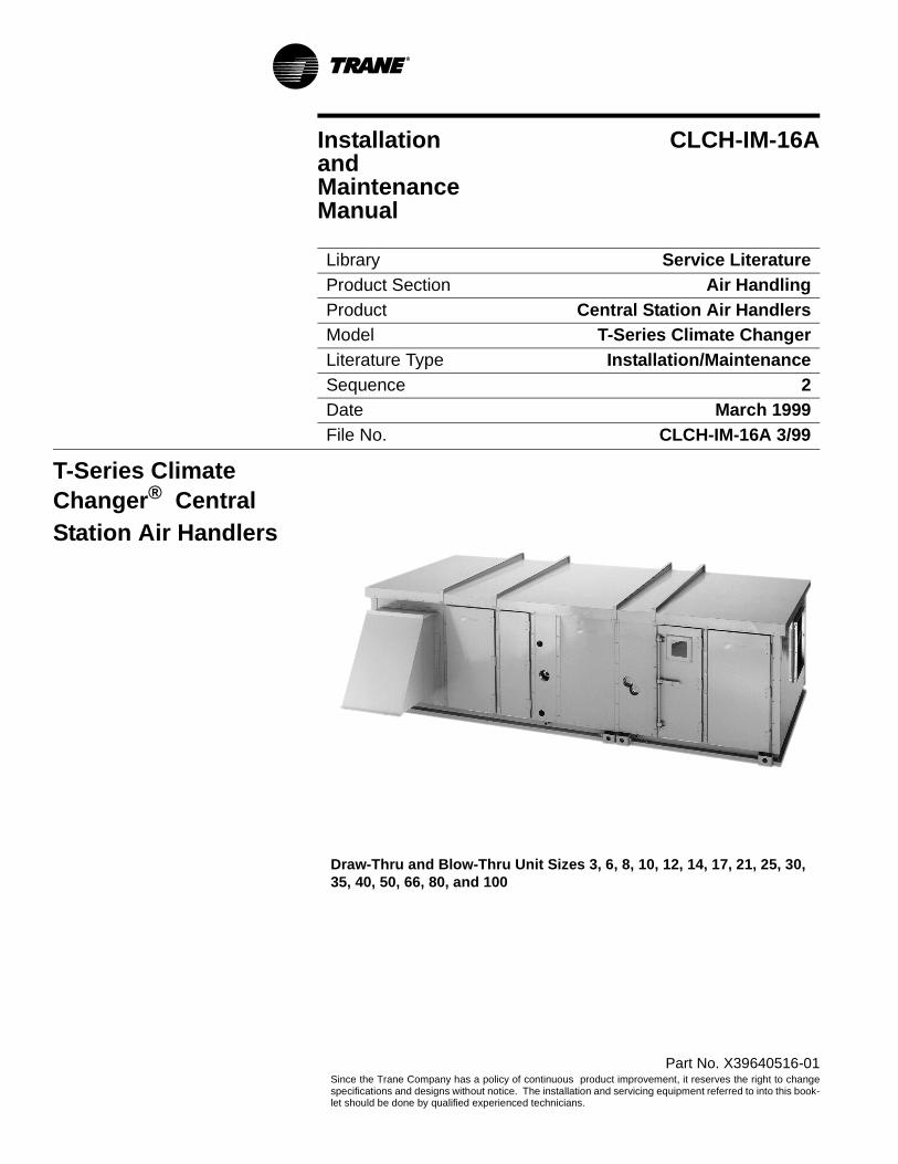
Part No. X39640516-01 Since the Trane Company has a policy of continuous product improvement, it reserves the right to change specifications and designs without notice. The installation and servicing equipment referred to into this book- let should be done by qualified experienced technicians. Installation CLCH-IM-16A and Maintenance Manual Library Service Literature Product Section Air Handling Product Central Station Air Handlers Model T-Series Climate Changer Literature Type Installation/Maintenance Sequence 2 Date March 1999 File No. CLCH-IM-16A 3/99 T-Series Climate Changer ® Central Station Air Handlers Draw-Thru and Blow-Thru Unit Sizes 3, 6, 8, 10, 12, 14, 17, 21, 25, 30, 35, 40, 50, 66, 80, and 100
Transcript of T-Series Climate Changer ® Central Station Air Handlers Installation ...
Part No. X39640516-01Since the Trane Company has a policy of continuous product improvement, it reserves the right to changespecifications and designs without notice. The installation and servicing equipment referred to into this book-let should be done by qualified experienced technicians.
Installation CLCH-IM-16AandMaintenanceManual
Library Service LiteratureProduct Section Air HandlingProduct Central Station Air HandlersModel T-Series Climate ChangerLiterature Type Installation/MaintenanceSequence 2Date March 1999File No. CLCH-IM-16A 3/99
T-Series Climate Changer® CentralStation Air Handlers
Draw-Thru and Blow-Thru Unit Sizes 3, 6, 8, 10, 12, 14, 17, 21, 25, 30, 35, 40, 50, 66, 80, and 100
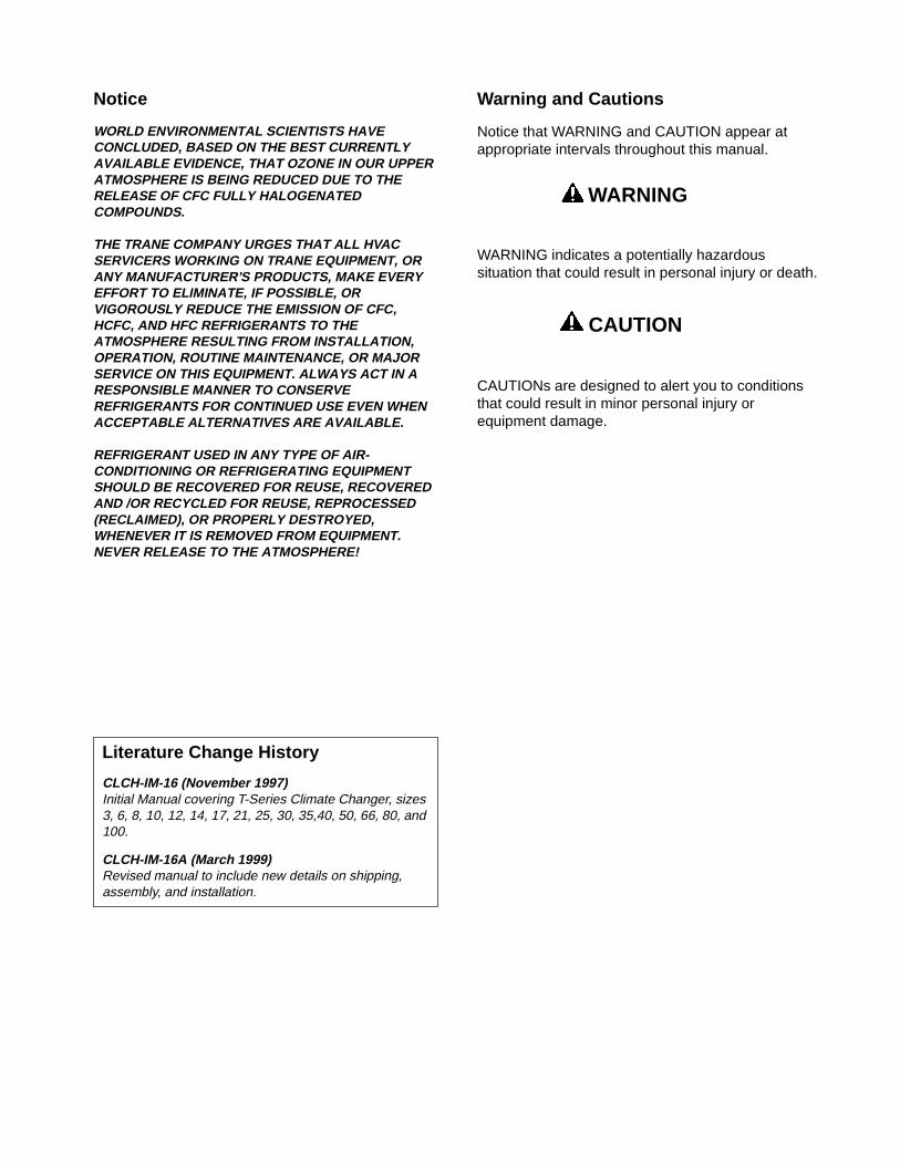
Notice
WORLD ENVIRONMENTAL SCIENTISTS HAVE CONCLUDED, BASED ON THE BEST CURRENTLY AVAILABLE EVIDENCE, THAT OZONE IN OUR UPPER ATMOSPHERE IS BEING REDUCED DUE TO THE RELEASE OF CFC FULLY HALOGENATED COMPOUNDS.
THE TRANE COMPANY URGES THAT ALL HVAC SERVICERS WORKING ON TRANE EQUIPMENT, OR ANY MANUFACTURER’S PRODUCTS, MAKE EVERY EFFORT TO ELIMINATE, IF POSSIBLE, OR VIGOROUSLY REDUCE THE EMISSION OF CFC, HCFC, AND HFC REFRIGERANTS TO THE ATMOSPHERE RESULTING FROM INSTALLATION, OPERATION, ROUTINE MAINTENANCE, OR MAJOR SERVICE ON THIS EQUIPMENT. ALWAYS ACT IN A RESPONSIBLE MANNER TO CONSERVE REFRIGERANTS FOR CONTINUED USE EVEN WHEN ACCEPTABLE ALTERNATIVES ARE AVAILABLE.
REFRIGERANT USED IN ANY TYPE OF AIR-CONDITIONING OR REFRIGERATING EQUIPMENT SHOULD BE RECOVERED FOR REUSE, RECOVERED AND /OR RECYCLED FOR REUSE, REPROCESSED (RECLAIMED), OR PROPERLY DESTROYED, WHENEVER IT IS REMOVED FROM EQUIPMENT. NEVER RELEASE TO THE ATMOSPHERE!
Warning and Cautions
Notice that WARNING and CAUTION appear at appropriate intervals throughout this manual.
WARNING
WARNING indicates a potentially hazardous situation that could result in personal injury or death.
CAUTION
CAUTIONs are designed to alert you to conditions that could result in minor personal injury or equipment damage.
Literature Change History
CLCH-IM-16 (November 1997)Initial Manual covering T-Series Climate Changer, sizes 3, 6, 8, 10, 12, 14, 17, 21, 25, 30, 35,40, 50, 66, 80, and 100.
CLCH-IM-16A (March 1999)Revised manual to include new details on shipping, assembly, and installation.
T-Series Climate Changer
Table of Contents
General Information ............................................. 1
Unit Description .................................................. 1Operating Environment ....................................... 1Unit Nameplates ................................................. 1Controls .............................................................. 2
Receiving .............................................................. 3
Storage Considerations ...................................... 3
Rigging and Handling .......................................... 4
Determine Unit Weights ...................................... 4Lifting Instructions ............................................. 12
Installation .......................................................... 15
Unit Assembly .................................................... 16
General ............................................................. 16Unit Assembly - All Sizes .................................. 16Component Installation Requirements ............. 22Fan Section ...................................................... 22
Set-Up ................................................................. 25
Duct Connections ............................................. 28Drain Pan .......................................................... 30Coil Piping And Connections ............................ 32Refrigerant Coil Piping ...................................... 46General Refrigerant Piping Recommendations 47Wiring ............................................................... 49
Installation Checklist ......................................... 51
Prestart-Up Checks .......................................... 51
Start-Up ............................................................... 53
Start-Up Procedures ......................................... 53
Periodic Maintenance ........................................ 59
Drain Pans ........................................................ 60Air Filters .......................................................... 60Fans .................................................................. 61Fan Bearings and Motors ................................. 61Coil Cleaning .................................................... 63Coil Winterization .............................................. 65
Troubleshooting ................................................. 66
Installation and Maintenance 1
*HQHUDO�,QIRUPDWLRQ
Unit Description
Trane T-Series Climate Changers® are Central Station Air Handlers designed for a variety of air handling applications. The basic unit consists of a fan, heating and/or cooling coils, filters, and dampers. See the sales catalog (CLCH-DS-9) for a list of available options and components.
The fan is internally isolated. Fans available are double-width, double-inlet Centrifugal types with forward curved, backward inclined, or airfoil blade type design; single-width, single-inlet Plug Fans or Vane-Axial Q Fans®. Fans are available in low, medium, and high pressure classes with or without inlet guide vanes.
To insure fan stability, the unit ships with four (4) lock-down devices that prevent the fan from shifting during shipment and installation. These spacers must be removed prior to fan operation to assure proper vibration isolation.
The units are available with factory-mounted controls for stand-alone operation or operation with a complete building automation system. This includes factory-mounted starters, DDC controllers, and end devices.
Trane T-Series Climate Changers ship as complete assemblies or sectional subassemblies. Some assembly is required when the units ship as subassemblies.
Operating Environment
The T-Series Climate Changer (TSC) is an outdoor air handler. When considering the placement of the TSC it is important to consider the operating environment. The acceptable ambient temperature range for unit operation is -40° to +140°F (-40°C to 60°C).
For heating applications a special motor may be required to withstand the higher temperatures. Motors with Class “B” insulation are acceptable for ambient temperatures up to 104°F while motors with class “F” insulation can withstand ambient temperatures to +140° F (60°C).
NOTE: IT IS RECOMMENDED THAT THE CUSTOMER PROVIDE ADEQUATE FREEZE PROTECTION FOR THE COILS.UNITS WITH UL APPROVAL HAVE A MAXIMUM AMBIENT TEMPERATURE REQUIREMENT OF 104°F.
Unit Nameplates
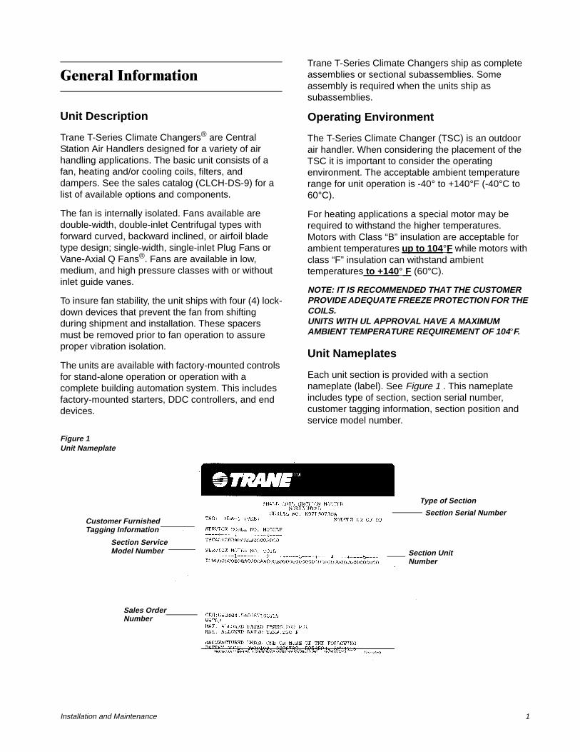
Each unit section is provided with a section nameplate (label). See Figure 1 . This nameplate includes type of section, section serial number, customer tagging information, section position and service model number.
Figure 1Unit Nameplate
Customer Furnished
Section ServiceModel Number
Sales OrderNumber
Type of Section
Section Serial Number
Section UnitNumber
Tagging Information
2 CLCH-IM-16A
Each section of a T-Series Climate Changer is identified with a multi-character model number and serial number. The model number precisely identifies a particular section. Refer to model number and serial number when ordering parts or requesting service.
If the unit ships as individual sections or section subassemblies refer to the nameplate for customer tagging information and section position to insure proper placement of the sections during assembly.
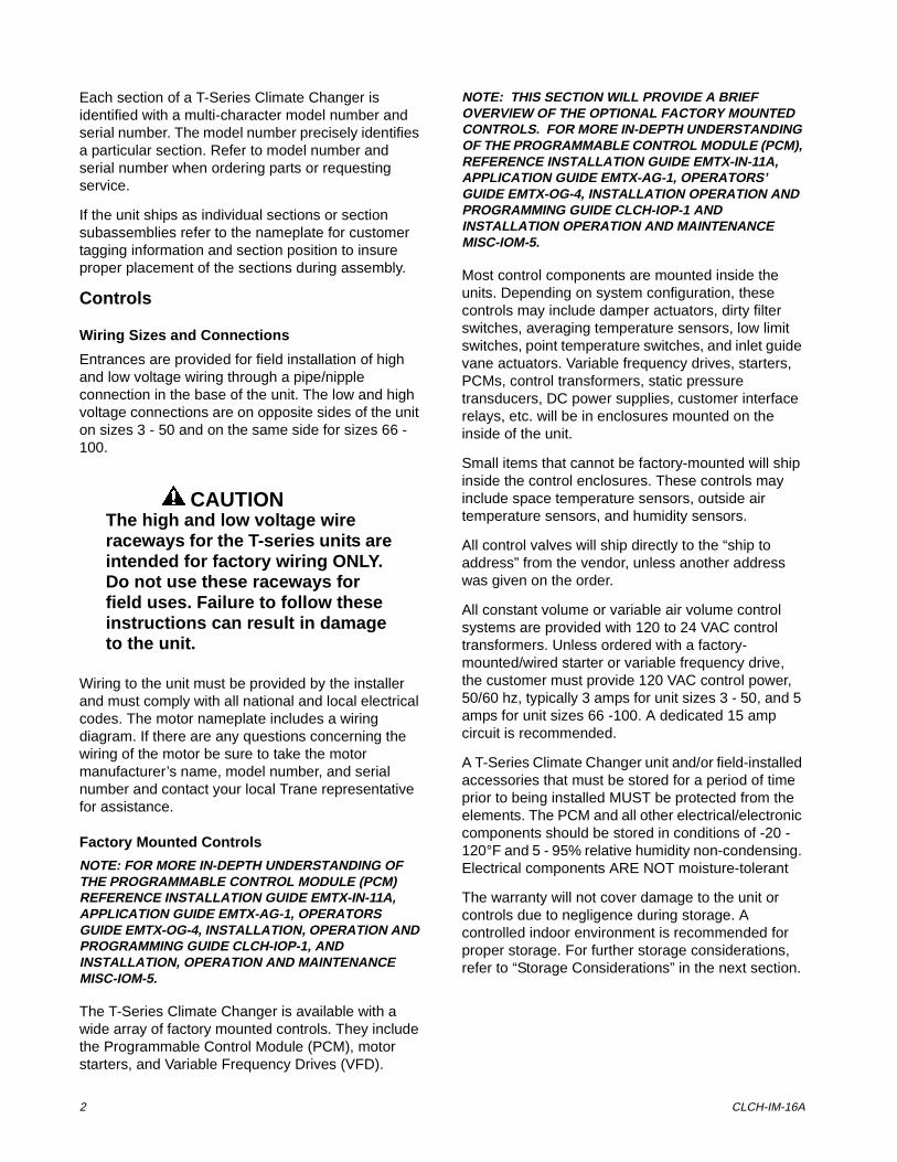
Controls
Wiring Sizes and Connections
Entrances are provided for field installation of high and low voltage wiring through a pipe/nipple connection in the base of the unit. The low and high voltage connections are on opposite sides of the unit on sizes 3 - 50 and on the same side for sizes 66 -100.
CAUTIONThe high and low voltage wire raceways for the T-series units are intended for factory wiring ONLY. Do not use these raceways for field uses. Failure to follow these instructions can result in damage to the unit.
Wiring to the unit must be provided by the installer and must comply with all national and local electrical codes. The motor nameplate includes a wiring diagram. If there are any questions concerning the wiring of the motor be sure to take the motor manufacturer’s name, model number, and serial number and contact your local Trane representative for assistance.
Factory Mounted Controls
NOTE: FOR MORE IN-DEPTH UNDERSTANDING OF THE PROGRAMMABLE CONTROL MODULE (PCM) REFERENCE INSTALLATION GUIDE EMTX-IN-11A, APPLICATION GUIDE EMTX-AG-1, OPERATORS GUIDE EMTX-OG-4, INSTALLATION, OPERATION AND PROGRAMMING GUIDE CLCH-IOP-1, AND INSTALLATION, OPERATION AND MAINTENANCE MISC-IOM-5.
The T-Series Climate Changer is available with a wide array of factory mounted controls. They include the Programmable Control Module (PCM), motor starters, and Variable Frequency Drives (VFD).
NOTE: THIS SECTION WILL PROVIDE A BRIEF OVERVIEW OF THE OPTIONAL FACTORY MOUNTED CONTROLS. FOR MORE IN-DEPTH UNDERSTANDING OF THE PROGRAMMABLE CONTROL MODULE (PCM), REFERENCE INSTALLATION GUIDE EMTX-IN-11A, APPLICATION GUIDE EMTX-AG-1, OPERATORS’ GUIDE EMTX-OG-4, INSTALLATION OPERATION AND PROGRAMMING GUIDE CLCH-IOP-1 AND INSTALLATION OPERATION AND MAINTENANCE MISC-IOM-5.
Most control components are mounted inside the units. Depending on system configuration, these controls may include damper actuators, dirty filter switches, averaging temperature sensors, low limit switches, point temperature switches, and inlet guide vane actuators. Variable frequency drives, starters, PCMs, control transformers, static pressure transducers, DC power supplies, customer interface relays, etc. will be in enclosures mounted on the inside of the unit.
Small items that cannot be factory-mounted will ship inside the control enclosures. These controls may include space temperature sensors, outside air temperature sensors, and humidity sensors.
All control valves will ship directly to the “ship to address” from the vendor, unless another address was given on the order.
All constant volume or variable air volume control systems are provided with 120 to 24 VAC control transformers. Unless ordered with a factory-mounted/wired starter or variable frequency drive, the customer must provide 120 VAC control power, 50/60 hz, typically 3 amps for unit sizes 3 - 50, and 5 amps for unit sizes 66 -100. A dedicated 15 amp circuit is recommended.
A T-Series Climate Changer unit and/or field-installed accessories that must be stored for a period of time prior to being installed MUST be protected from the elements. The PCM and all other electrical/electronic components should be stored in conditions of -20 - 120°F and 5 - 95% relative humidity non-condensing. Electrical components ARE NOT moisture-tolerant
The warranty will not cover damage to the unit or controls due to negligence during storage. A controlled indoor environment is recommended for proper storage. For further storage considerations, refer to “Storage Considerations” in the next section.
Installation and Maintenance 3
5HFHLYLQJ
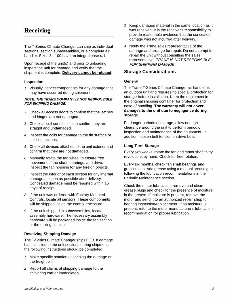
The T-Series Climate Changer can ship as individual sections, section subassemblies, or a complete air handler. Sizes 3 - 100 have an integral base rail.
Upon receipt of the unit(s) and prior to unloading, inspect the unit for damage and verify that the shipment is complete. Delivery cannot be refused.
Inspection
1 Visually inspect components for any damage that may have occurred during shipment.
NOTE: THE TRANE COMPANY IS NOT RESPONSIBLE FOR SHIPPING DAMAGE.
2 Check all access doors to confirm that the latches and hinges are not damaged.
3 Check all coil connections to confirm they are straight and undamaged.
4 Inspect the coils for damage to the fin surface or coil connections.
5 Check all devices attached to the unit exterior and confirm that they are not damaged.
6 Manually rotate the fan wheel to ensure free movement of the shaft, bearings, and drive. Inspect the fan housing for any foreign objects.
7 Inspect the interior of each section for any internal damage as soon as possible after delivery. Concealed damage must be reported within 15 days of receipt.
8 If the unit was ordered with Factory Mounted Controls, locate all sensors. These components will be shipped inside the control enclosure.
9 If the unit shipped in subassemblies, locate assembly hardware. The necessary assembly hardware will be packaged inside the fan section or the mixing section.
Resolving Shipping Damage
The T-Series Climate Changer ships FOB. If damage has occurred to the unit sections during shipment, the following instructions should be completed:
1 Make specific notation describing the damage on the freight bill.
2 Report all claims of shipping damage to the delivering carrier immediately.
3 Keep damaged material in the same location as it was received. It is the receiver’s responsibility to provide reasonable evidence that the concealed damage was not incurred after delivery.
4 Notify the Trane sales representative of the damage and arrange for repair. Do not attempt to repair the unit without consulting the sales representative. TRANE IS NOT RESPONSIBLE FOR SHIPPING DAMAGE.
Storage Considerations
General
The Trane T-Series Climate Changer air handler is an outdoor unit and requires no special protection for storage before installation. Keep the equipment in the original shipping container for protection and ease of handling. The warranty will not cover damages to the unit due to negligence during storage.
For longer periods of storage, allow enough clearance around the unit to perform periodic inspection and maintenance of the equipment. In addition, loosen belt tension on drive belts.
Long Term Storage
Every two weeks, rotate the fan and motor shaft thirty revolutions by hand. Check for free rotation.
Every six months, check fan shaft bearings and grease lines. Add grease using a manual grease gun following the lubrication recommendations in the Periodic Maintenance section.
Check the motor lubrication; remove and clean grease plugs and check for the presence of moisture in the grease. If moisture is present, remove the motor and send it to an authorized repair shop for bearing inspection/replacement. If no moisture is present, refer to the motor manufacturer’s lubrication recommendation for proper lubrication.
4 CLCH-IM-16A
5LJJLQJ�DQG�+DQGOLQJ
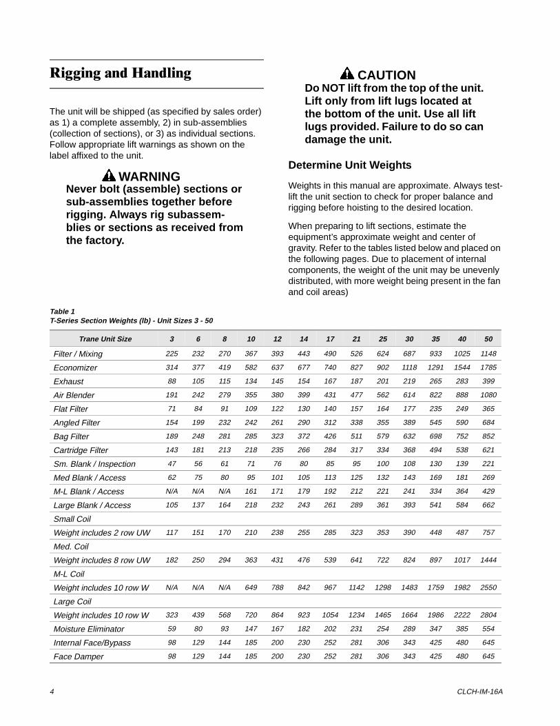
The unit will be shipped (as specified by sales order) as 1) a complete assembly, 2) in sub-assemblies (collection of sections), or 3) as individual sections. Follow appropriate lift warnings as shown on the label affixed to the unit.
WARNINGNever bolt (assemble) sections or sub-assemblies together before rigging. Always rig subassem-blies or sections as received from the factory.
CAUTIONDo NOT lift from the top of the unit. Lift only from lift lugs located at the bottom of the unit. Use all lift lugs provided. Failure to do so can damage the unit.
Determine Unit Weights
Weights in this manual are approximate. Always test-lift the unit section to check for proper balance and rigging before hoisting to the desired location.
When preparing to lift sections, estimate the equipment’s approximate weight and center of gravity. Refer to the tables listed below and placed on the following pages. Due to placement of internal components, the weight of the unit may be unevenly distributed, with more weight being present in the fan and coil areas)
Table 1T-Series Section Weights (lb) - Unit Sizes 3 - 50
Trane Unit Size 3 6 8 10 12 14 17 21 25 30 35 40 50
Filter / Mixing 225 232 270 367 393 443 490 526 624 687 933 1025 1148
Economizer 314 377 419 582 637 677 740 827 902 1118 1291 1544 1785
Exhaust 88 105 115 134 145 154 167 187 201 219 265 283 399
Air Blender 191 242 279 355 380 399 431 477 562 614 822 888 1080
Flat Filter 71 84 91 109 122 130 140 157 164 177 235 249 365
Angled Filter 154 199 232 242 261 290 312 338 355 389 545 590 684
Bag Filter 189 248 281 285 323 372 426 511 579 632 698 752 852
Cartridge Filter 143 181 213 218 235 266 284 317 334 368 494 538 621
Sm. Blank / Inspection 47 56 61 71 76 80 85 95 100 108 130 139 221
Med Blank / Access 62 75 80 95 101 105 113 125 132 143 169 181 269
M-L Blank / Access N/A N/A N/A 161 171 179 192 212 221 241 334 364 429
Large Blank / Access 105 137 164 218 232 243 261 289 361 393 541 584 662
Small Coil
Weight includes 2 row UW 117 151 170 210 238 255 285 323 353 390 448 487 757
Med. Coil
Weight includes 8 row UW 182 250 294 363 431 476 539 641 722 824 897 1017 1444
M-L Coil
Weight includes 10 row W N/A N/A N/A 649 788 842 967 1142 1298 1483 1759 1982 2550
Large Coil
Weight includes 10 row W 323 439 568 720 864 923 1054 1234 1465 1664 1986 2222 2804
Moisture Eliminator 59 80 93 147 167 182 202 231 254 289 347 385 554
Internal Face/Bypass 98 129 144 185 200 230 252 281 306 343 425 480 645
Face Damper 98 129 144 185 200 230 252 281 306 343 425 480 645
Installation and Maintenance 5
.
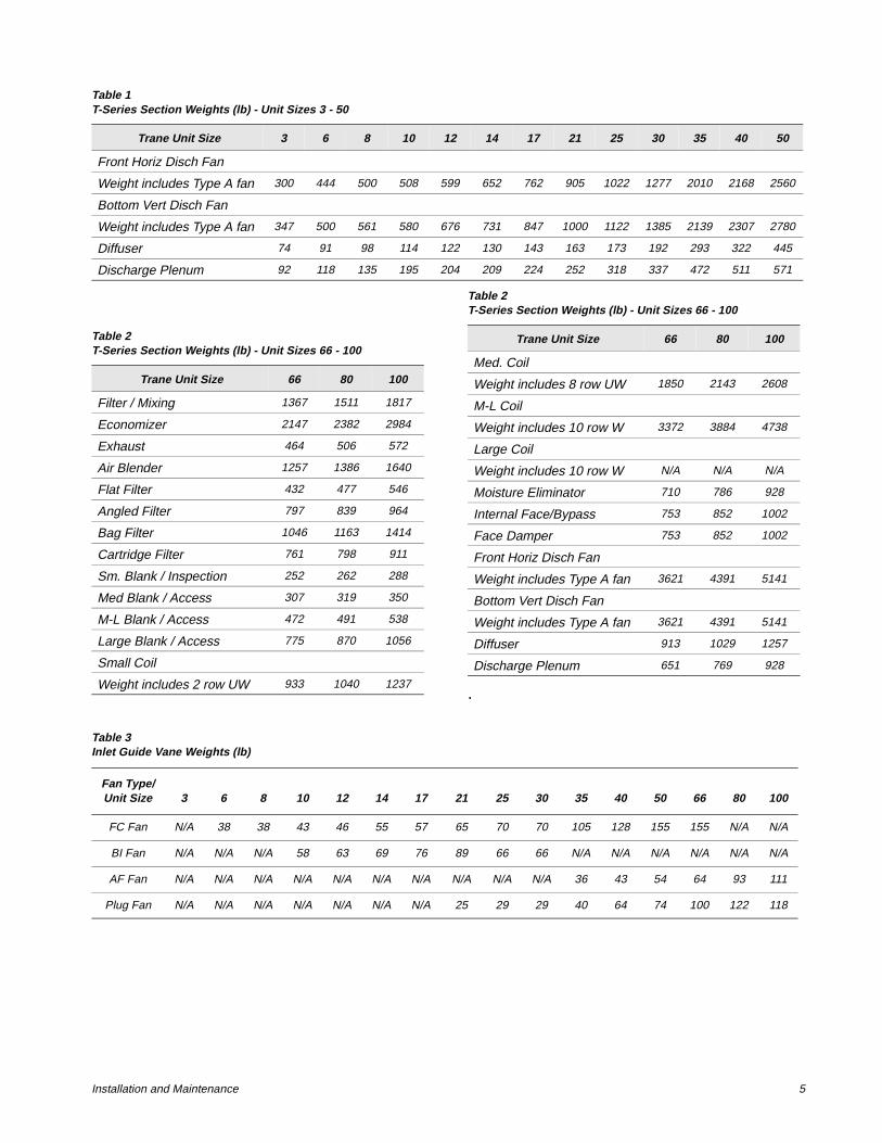
Front Horiz Disch Fan
Weight includes Type A fan 300 444 500 508 599 652 762 905 1022 1277 2010 2168 2560
Bottom Vert Disch Fan
Weight includes Type A fan 347 500 561 580 676 731 847 1000 1122 1385 2139 2307 2780
Diffuser 74 91 98 114 122 130 143 163 173 192 293 322 445
Discharge Plenum 92 118 135 195 204 209 224 252 318 337 472 511 571
Table 1T-Series Section Weights (lb) - Unit Sizes 3 - 50
Trane Unit Size 3 6 8 10 12 14 17 21 25 30 35 40 50
Table 2T-Series Section Weights (lb) - Unit Sizes 66 - 100
Trane Unit Size 66 80 100
Filter / Mixing 1367 1511 1817
Economizer 2147 2382 2984
Exhaust 464 506 572
Air Blender 1257 1386 1640
Flat Filter 432 477 546
Angled Filter 797 839 964
Bag Filter 1046 1163 1414
Cartridge Filter 761 798 911
Sm. Blank / Inspection 252 262 288
Med Blank / Access 307 319 350
M-L Blank / Access 472 491 538
Large Blank / Access 775 870 1056
Small Coil
Weight includes 2 row UW 933 1040 1237
Med. Coil
Weight includes 8 row UW 1850 2143 2608
M-L Coil
Weight includes 10 row W 3372 3884 4738
Large Coil
Weight includes 10 row W N/A N/A N/A
Moisture Eliminator 710 786 928
Internal Face/Bypass 753 852 1002
Face Damper 753 852 1002
Front Horiz Disch Fan
Weight includes Type A fan 3621 4391 5141
Bottom Vert Disch Fan
Weight includes Type A fan 3621 4391 5141
Diffuser 913 1029 1257
Discharge Plenum 651 769 928
Table 2T-Series Section Weights (lb) - Unit Sizes 66 - 100
Trane Unit Size 66 80 100
Table 3Inlet Guide Vane Weights (lb)
Fan Type/Unit Size 3 6 8 10 12 14 17 21 25 30 35 40 50 66 80 100
FC Fan N/A 38 38 43 46 55 57 65 70 70 105 128 155 155 N/A N/A
BI Fan N/A N/A N/A 58 63 69 76 89 66 66 N/A N/A N/A N/A N/A N/A
AF Fan N/A N/A N/A N/A N/A N/A N/A N/A N/A N/A 36 43 54 64 93 111
Plug Fan N/A N/A N/A N/A N/A N/A N/A 25 29 29 40 64 74 100 122 118
6 CLCH-IM-16A
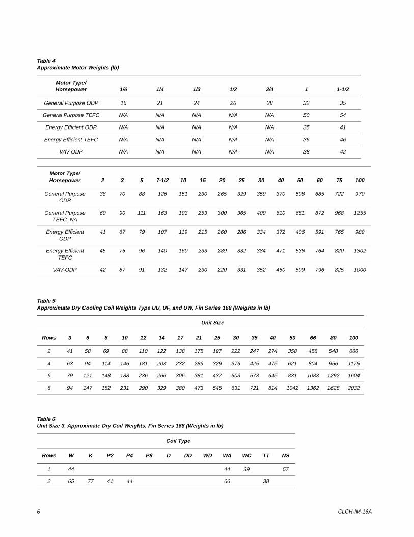
Table 4Approximate Motor Weights (lb)
Motor Type/Horsepower 1/6 1/4 1/3 1/2 3/4 1 1-1/2
General Purpose ODP 16 21 24 26 28 32 35
General Purpose TEFC N/A N/A N/A N/A N/A 50 54
Energy Efficient ODP N/A N/A N/A N/A N/A 35 41
Energy Efficient TEFC N/A N/A N/A N/A N/A 36 46
VAV-ODP N/A N/A N/A N/A N/A 38 42
Motor Type/Horsepower 2 3 5 7-1/2 10 15 20 25 30 40 50 60 75 100
General Purpose ODP
38 70 88 126 151 230 265 329 359 370 508 685 722 970
General Purpose TEFC NA
60 90 111 163 193 253 300 365 409 610 681 872 968 1255
Energy Efficient ODP
41 67 79 107 119 215 260 286 334 372 406 591 765 989
Energy Efficient TEFC
45 75 96 140 160 233 289 332 384 471 536 764 820 1302
VAV-ODP 42 87 91 132 147 230 220 331 352 450 509 796 825 1000
Table 5Approximate Dry Cooling Coil Weights Type UU, UF, and UW, Fin Series 168 (Weights in lb)
Unit Size
Rows 3 6 8 10 12 14 17 21 25 30 35 40 50 66 80 100
2 41 58 69 88 110 122 138 175 197 222 247 274 358 458 548 666
4 63 94 114 146 181 203 232 289 329 376 425 475 621 804 956 1175
6 79 121 148 188 236 266 306 381 437 503 573 645 831 1083 1292 1604
8 94 147 182 231 290 329 380 473 545 631 721 814 1042 1362 1628 2032
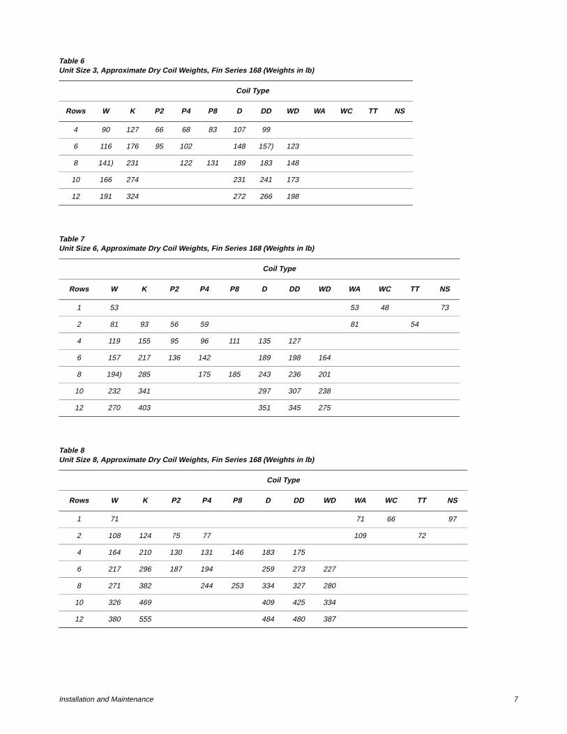
Table 6Unit Size 3, Approximate Dry Coil Weights, Fin Series 168 (Weights in lb)
Coil Type
Rows W K P2 P4 P8 D DD WD WA WC TT NS
1 44 44 39 57
2 65 77 41 44 66 38
Installation and Maintenance 7
4 90 127 66 68 83 107 99
6 116 176 95 102 148 157) 123
8 141) 231 122 131 189 183 148
10 166 274 231 241 173
12 191 324 272 266 198
Table 6Unit Size 3, Approximate Dry Coil Weights, Fin Series 168 (Weights in lb)
Coil Type
Rows W K P2 P4 P8 D DD WD WA WC TT NS
Table 7Unit Size 6, Approximate Dry Coil Weights, Fin Series 168 (Weights in lb)
Coil Type
Rows W K P2 P4 P8 D DD WD WA WC TT NS
1 53 53 48 73
2 81 93 56 59 81 54
4 119 155 95 96 111 135 127
6 157 217 136 142 189 198 164
8 194) 285 175 185 243 236 201
10 232 341 297 307 238
12 270 403 351 345 275
Table 8Unit Size 8, Approximate Dry Coil Weights, Fin Series 168 (Weights in lb)
Coil Type
Rows W K P2 P4 P8 D DD WD WA WC TT NS
1 71 71 66 97
2 108 124 75 77 109 72
4 164 210 130 131 146 183 175
6 217 296 187 194 259 273 227
8 271 382 244 253 334 327 280
10 326 469 409 425 334
12 380 555 484 480 387
8 CLCH-IM-16A
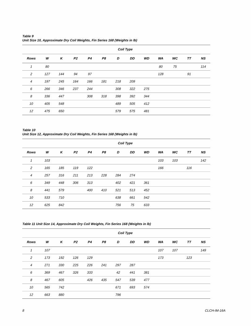
Table 9Unit Size 10, Approximate Dry Coil Weights, Fin Series 168 (Weights in lb)
Coil Type
Rows W K P2 P4 P8 D DD WD WA WC TT NS
1 80 80 75 114
2 127 144 94 97 128 91
4 197 245 164 166 181 218 209
6 266 346 237 244 308 322 275
8 336 447 308 318 398 392 344
10 405 548 489 505 412
12 475 650 579 575 481
Table 10Unit Size 12, Approximate Dry Coil Weights, Fin Series 168 (Weights in lb)
Coil Type
Rows W K P2 P4 P8 D DD WD WA WC TT NS
1 103 103 103 142
2 165 185 119 122 166 116
4 257 316 211 213 228 284 274
6 349 448 306 313 402 421 361
8 441 579 400 410 521 513 452
10 533 710 638 661 542
12 625 842 756 75 633
Table 11 Unit Size 14, Approximate Dry Coil Weights, Fin Series 168 (Weights in lb)
Coil Type
Rows W K P2 P4 P8 D DD WD WA WC TT NS
1 107 107 107 149
2 173 192 126 129 173 123
4 271 330 225 226 241 297 287
6 369 467 326 333 42 441 381
8 467 605 426 435 547 539 477
10 565 742 671 693 574
12 663 880 796
Installation and Maintenance 9
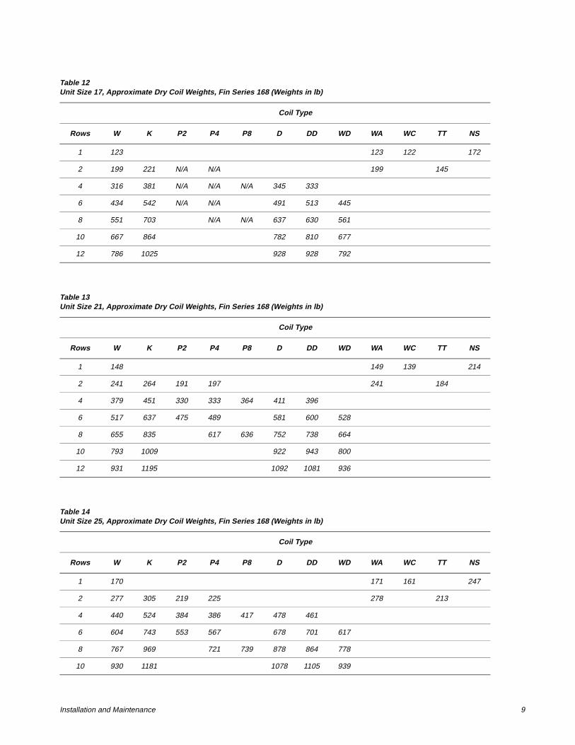
Table 12Unit Size 17, Approximate Dry Coil Weights, Fin Series 168 (Weights in lb)
Coil Type
Rows W K P2 P4 P8 D DD WD WA WC TT NS
1 123 123 122 172
2 199 221 N/A N/A 199 145
4 316 381 N/A N/A N/A 345 333
6 434 542 N/A N/A 491 513 445
8 551 703 N/A N/A 637 630 561
10 667 864 782 810 677
12 786 1025 928 928 792
Table 13Unit Size 21, Approximate Dry Coil Weights, Fin Series 168 (Weights in lb)
Coil Type
Rows W K P2 P4 P8 D DD WD WA WC TT NS
1 148 149 139 214
2 241 264 191 197 241 184
4 379 451 330 333 364 411 396
6 517 637 475 489 581 600 528
8 655 835 617 636 752 738 664
10 793 1009 922 943 800
12 931 1195 1092 1081 936
Table 14Unit Size 25, Approximate Dry Coil Weights, Fin Series 168 (Weights in lb)
Coil Type
Rows W K P2 P4 P8 D DD WD WA WC TT NS
1 170 171 161 247
2 277 305 219 225 278 213
4 440 524 384 386 417 478 461
6 604 743 553 567 678 701 617
8 767 969 721 739 878 864 778
10 930 1181 1078 1105 939
10 CLCH-IM-16A
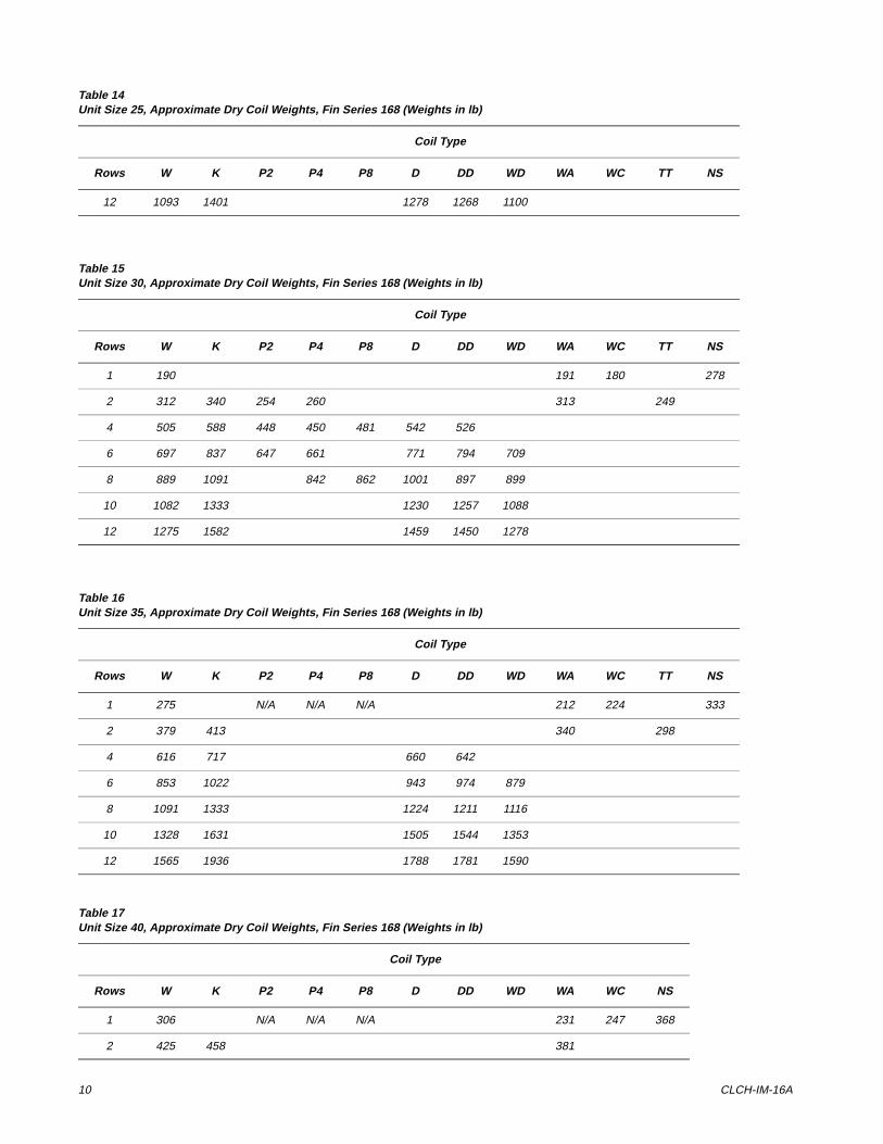
12 1093 1401 1278 1268 1100
Table 14Unit Size 25, Approximate Dry Coil Weights, Fin Series 168 (Weights in lb)
Coil Type
Rows W K P2 P4 P8 D DD WD WA WC TT NS
Table 15Unit Size 30, Approximate Dry Coil Weights, Fin Series 168 (Weights in lb)
Coil Type
Rows W K P2 P4 P8 D DD WD WA WC TT NS
1 190 191 180 278
2 312 340 254 260 313 249
4 505 588 448 450 481 542 526
6 697 837 647 661 771 794 709
8 889 1091 842 862 1001 897 899
10 1082 1333 1230 1257 1088
12 1275 1582 1459 1450 1278
Table 16Unit Size 35, Approximate Dry Coil Weights, Fin Series 168 (Weights in lb)
Coil Type
Rows W K P2 P4 P8 D DD WD WA WC TT NS
1 275 N/A N/A N/A 212 224 333
2 379 413 340 298
4 616 717 660 642
6 853 1022 943 974 879
8 1091 1333 1224 1211 1116
10 1328 1631 1505 1544 1353
12 1565 1936 1788 1781 1590
Table 17Unit Size 40, Approximate Dry Coil Weights, Fin Series 168 (Weights in lb)
Coil Type
Rows W K P2 P4 P8 D DD WD WA WC NS
1 306 N/A N/A N/A 231 247 368
2 425 458 381
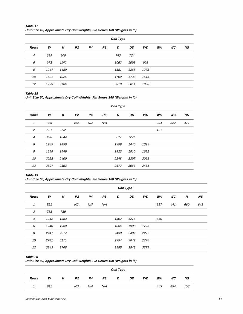
Installation and Maintenance 11
4 699 800 743 724
6 973 1142 1062 1093 998
8 1247 1489 1381 1368 1273
10 1521 1825 1700 1738 1546
12 1795 2166 2018 2011 1820
Table 18Unit Size 50, Approximate Dry Coil Weights, Fin Series 168 (Weights in lb)
Coil Type
Rows W K P2 P4 P8 D DD WD WA WC NS
1 386 N/A N/A N/A 294 322 477
2 551 592 491
4 920 1044 975 953
6 1289 1496 1399 1440 1323
8 1658 1949 1823 1810 1692
10 2028 2400 2248 2297 2061
12 2397 2853 2672 2666 2431
Table 19Unit Size 66, Approximate Dry Coil Weights, Fin Series 168 (Weights in lb)
Coil Type
Rows W K P2 P4 P8 D DD WD WA WC N NS
1 521 N/A N/A N/A 387 441 660 648
2 738 789
4 1242 1383 1302 1275 660
6 1740 1980 1866 1908 1776
8 2241 2577 2430 2409 2277
10 2742 3171 2994 3042 2778
12 3243 3768 3555 3543 3279
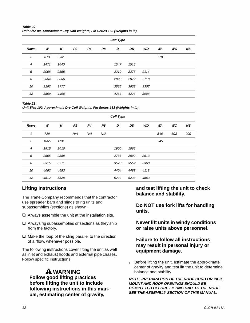
Table 20Unit Size 80, Approximate Dry Coil Weights, Fin Series 168 (Weights in lb)
Coil Type
Rows W K P2 P4 P8 D DD WD WA WC NS
1 611 N/A N/A N/A 453 494 753
Table 17Unit Size 40, Approximate Dry Coil Weights, Fin Series 168 (Weights in lb)
Coil Type
Rows W K P2 P4 P8 D DD WD WA WC NS
12 CLCH-IM-16A
Lifting Instructions
The Trane Company recommends that the contractor use spreader bars and slings to rig units and subassemblies (sections) as shown.
q Always assemble the unit at the installation site.
q Always rig subassemblies or sections as they ship from the factory.
q Make the loop of the sling parallel to the direction of airflow, whenever possible.
The following instructions cover lifting the unit as well as inlet and exhaust hoods and external pipe chases. Follow specific instructions.
WARNINGFollow good lifting practices before lifting the unit to include following instructions in this man-ual, estimating center of gravity,
and test lifting the unit to check balance and stability.
Do NOT use fork lifts for handling units.
Never lift units in windy conditions or raise units above personnel.
Failure to follow all instructions may result in personal injury or equipment damage.
1 Before lifting the unit, estimate the approximate center of gravity and test lift the unit to determine balance and stability.
NOTE: PREPARATION OF THE ROOF CURB OR PIER MOUNT AND ROOF OPENINGS SHOULD BE COMPLETED BEFORE LIFTING UNIT TO THE ROOF. SEE THE ASSEMBLY SECTION OF THIS MANUAL.
2 873 932 778
4 1471 1643 1547 1516
6 2068 2355 2219 2275 2114
8 2664 3066 2893 2872 2710
10 3262 3777 3565 3632 3307
12 3859 4490 4268 4228 3904
Table 21Unit Size 100, Approximate Dry Coil Weights, Fin Series 168 (Weights in lb)
Coil Type
Rows W K P2 P4 P8 D DD WD WA WC NS
1 729 N/A N/A N/A 546 603 909
2 1065 1131 945
4 1815 2010 1900 1866
6 2565 2889 2733 2802 2613
8 3315 3771 3570 3552 3363
10 4062 4653 4404 4488 4113
12 4812 5529 5238 5238 4863
Table 20Unit Size 80, Approximate Dry Coil Weights, Fin Series 168 (Weights in lb)
Coil Type
Rows W K P2 P4 P8 D DD WD WA WC NS
Installation and Maintenance 13
USE ALL OF THE LIFT LUGS PROVIDED.
NEVER STACK THE PIPE CABINET AND INLET HOODS ON THE UNIT AS THE UNIT IS BEING LIFTED.
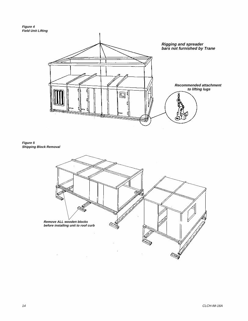
2 Lift all sections individually using all lifting lugs provided and shown in Figure 4 . See specific instructions for handling the inlet and exhaust hoods and pipe chase in paragraphs following.
3 Remove all wooden blocks before installing the unit to the roof curb (see Figure 5 ).
4 After the sections are in place, assemble them (see Unit Assembly).
Lifting Inlet and Exhaust Hoods
CAUTIONDo not attach the hood to the unit prior to lifting the unit. Doing so could damage the equipment.
Follow all warnings lifting instructions in the general Lifting section of this manual to include test lifting.
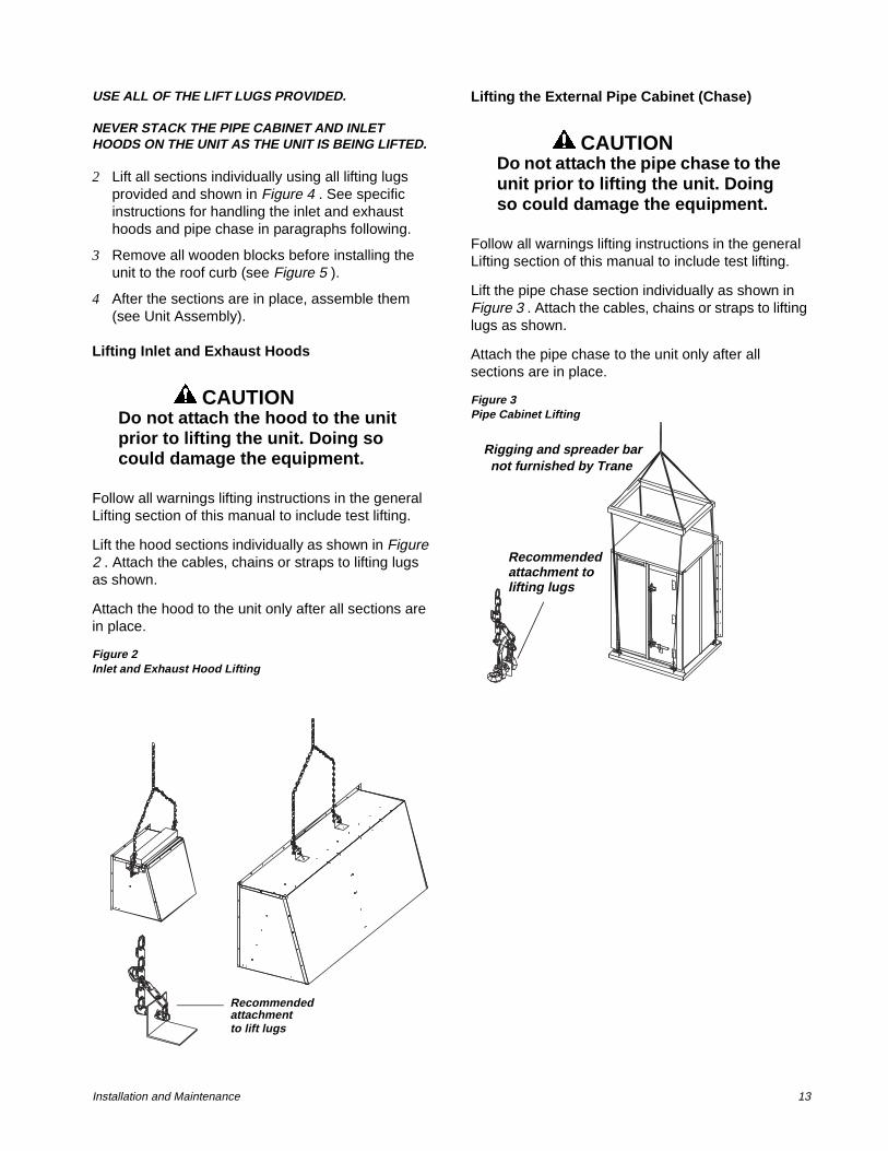
Lift the hood sections individually as shown in Figure 2 . Attach the cables, chains or straps to lifting lugs as shown.
Attach the hood to the unit only after all sections are in place.
Figure 2Inlet and Exhaust Hood Lifting
Lifting the External Pipe Cabinet (Chase)
CAUTIONDo not attach the pipe chase to the unit prior to lifting the unit. Doing so could damage the equipment.
Follow all warnings lifting instructions in the general Lifting section of this manual to include test lifting.
Lift the pipe chase section individually as shown in Figure 3 . Attach the cables, chains or straps to lifting lugs as shown.
Attach the pipe chase to the unit only after all sections are in place.
Figure 3Pipe Cabinet Lifting
Recommended
to lift lugsattachment
Rigging and spreader barnot furnished by Trane
Recommendedattachment tolifting lugs
14 CLCH-IM-16A
Figure 4Field Unit Lifting
Figure 5Shipping Block Removal
Rigging and spreaderbars not furnished by Trane
Recommended attachmentto lifting lugs
Remove ALL wooden blocksbefore installing unit to roof curb
Installation and Maintenance 15
,QVWDOODWLRQ�
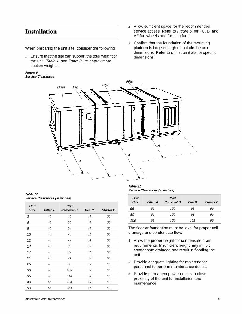
When preparing the unit site, consider the following:
1 Ensure that the site can support the total weight of the unit. Table 1 and Table 2 list approximate section weights.
2 Allow sufficient space for the recommended service access. Refer to Figure 6 for FC, BI and AF fan wheels and for plug fans.
3 Confirm that the foundation of the mounting platform is large enough to include the unit dimensions. Refer to unit submittals for specific dimensions.
Figure 6Service Clearances
The floor or foundation must be level for proper coil drainage and condensate flow.
4 Allow the proper height for condensate drain requirements. Insufficient height may inhibit condensate drainage and result in flooding the unit.
5 Provide adequate lighting for maintenance personnel to perform maintenance duties.
6 Provide permanent power outlets in close proximity of the unit for installation and maintenance.
CoilFilter
FanDrive
A
BC
D
Table 22Service Clearances (in inches)
Unit Size Filter A
Coil Removal B Fan C Starter D
3 48 48 48 60
6 48 60 48 60
8 48 64 48 60
10 48 75 51 60
12 48 79 54 60
14 48 83 58 60
17 48 89 61 60
21 48 91 60 60
25 48 93 66 60
30 48 106 66 60
35 48 110 65 60
40 48 123 70 60
50 48 134 77 60
66 52 150 93 60
80 56 150 91 60
100 58 165 101 60
Table 22Service Clearances (in inches)
Unit Size Filter A
Coil Removal B Fan C Starter D
16 CLCH-IM-16A
8QLW�$VVHPEO\
The T-Series Climate Changer is extremely versatile and can be assembled in many configurations. Prior to unit assembly, refer to the correct submittals and unit tagging for correct placement of accessory sections. Failure to review the submittal could result in performance or assembly problems. If there are any discrepancies, contact your local Trane representative before proceeding.
IMPORTANT: All shipping support screws on the face of the sections and sectional subassemblies must be removed and discarded to permit proper fit-up and sealing of the surfaces.
General
WARNINGTo avoid personal injury or death keep open flame away from unit exterior or interior. Do not weld or use cutting torch on the exterior or interior of the unit. The unit con-tains polyurethane insulation. Fail-ure to keep open flame away from unit exterior or interior may result in the production of toxic gas that could result in death or serious injury.
CAUTIONThe internal sections of this unit containing electrical components must not exceed 104o F tempera-ture. Internal sections of the unit not containing electrical compo-nents must not exceed 180o F tem-perature. Failure to comply with temperature requirements may cause equipment damage.
Units may be mounted on the roof with a roof curb or pier mount. Refer to submittals for dimensions and roof openings. Provide clearance around the unit to allow adequate free air and necessary service access. Also, allow room for supply and return
piping, ductwork, electrical connections, and coil removal.
The building roof must be able to support the entire weight of the unit, roof curb and accessories. See Table 1 thru Table 4 for unit and accessory weights.
q Prepare the roof curb or pier mount and roof openings before hoisting the unit to the roof.
q Check that the gasketing is intact and provides an airtight seal with the unit base. Refer to the applicable roof curb installation manual.
q Complete all ductwork, piping and electrical connections only after mounting the unit. Refer to unit submittals.
All T-Series Climate Changer units are identified by a multiple-character model number that identifies each section. It is located on the panel on the inside of the supply fan section access door. Be sure to refer to the information on the nameplate when ordering replacement parts or requesting service
Assembly Hardware
T-Series Climate Changers ship with all necessary assembly hardware and gasket material. This hardware is packaged in either a clear plastic envelope or cardboard box and can be found inside the Fan section, Access section, or Mixing section. The number of sections to be assembled often makes it necessary to use more than one section to ship the material. Please check all sections thoroughly before contacting your Trane Company Representative to report missing hardware.
Unit Assembly - All Sizes
Mounting
If a unit arrives in sections, then each section must be individually hoisted, set on a roof curb or pier mount and assembled.
The pipe cabinet must also be mounted as an individual section. Refer to the pipe cabinet assembly section following for specific instructions.
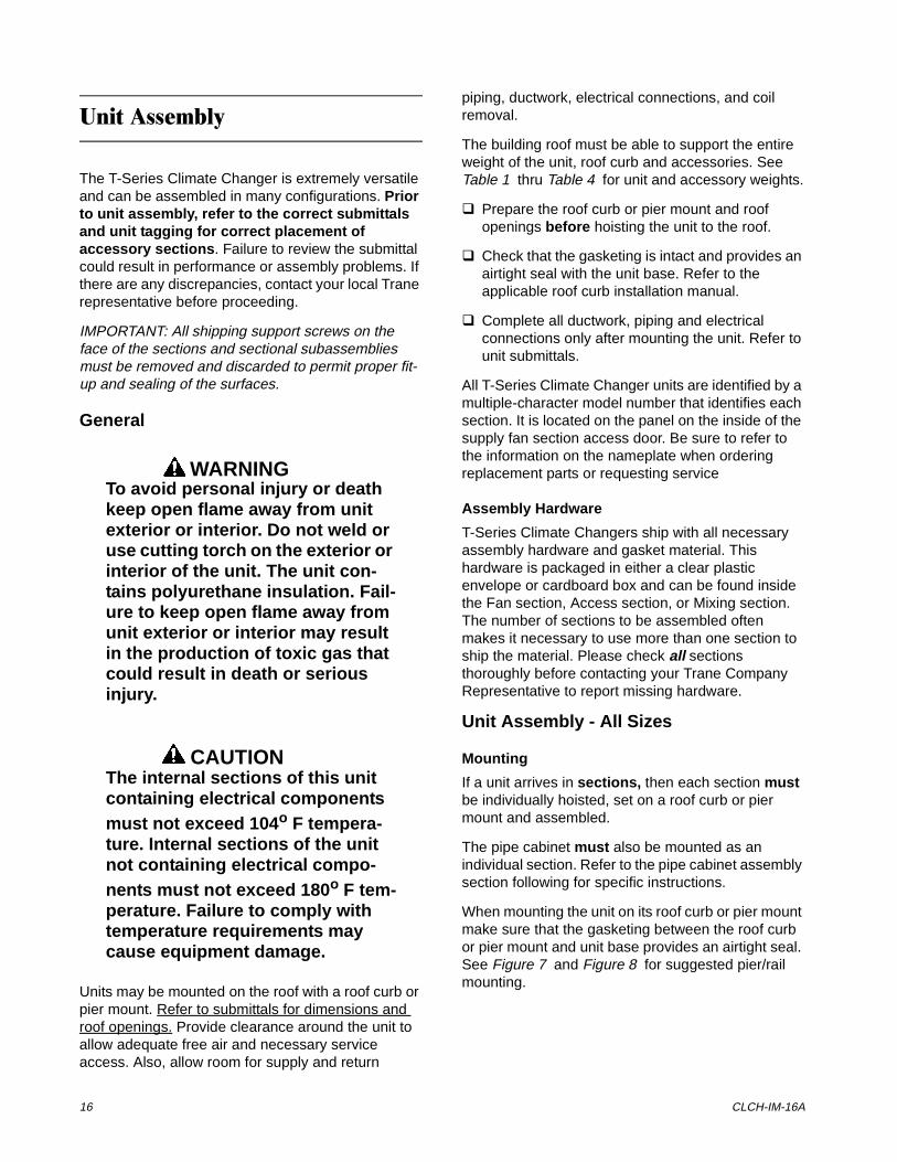
When mounting the unit on its roof curb or pier mount make sure that the gasketing between the roof curb or pier mount and unit base provides an airtight seal. See Figure 7 and Figure 8 for suggested pier/rail mounting.
Installation and Maintenance 17
Figure 7Pier Locations (Typical)
Figure 8Side View of Unit with Two Shipping Splits
NOTE: PIERS BENEATH SHIPPING SPLITS MUST BE STRUCTURALLY SOUND TO SUPPORT THE WEIGHT OF THE UNIT
Locate one pier at each corner, as a minimum, directly underneath any shipping split (ensure full support under each side), and then every four feet at equally spaced intervals around the perimeter of the unit. Both the unit and the pipe cabinet should be supported by their base channel around the entire perimeter.
CHECK THAT THE UNIT IS LEVEL TO ENSURE PROPER OPERATION.
IMPORTANT: FOR PROPER OPERATION, THE UNIT MUST BE INSTALLED LEVEL (ZERO TOLERANCE) IN BOTH HORIZONTAL AXES. FAILURE TO LEVEL THE UNIT PROPERLY CAN RESULT IN CONDENSATE MANAGEMENT PROBLEMS SUCH AS STANDING WATER INSIDE THE UNIT. STANDING WATER AND WET SURFACES INSIDE AIR HANDLING UNITS CAN RESULT IN MICROBIAL GROWTH (MOLD) IN THE DRAIN PAN THAT MAY CAUSE UNPLEASANT ODORS AND SERIOUS HEALTH-RELATED INDOOR AIR QUALITY PROBLEMS.
For vertical discharge units, allow space under the unit for supply air ductwork connections.
Assembling the Unit
Before sections are joined for final assembly, a butyl tape seal must be made at the roof connection and then hardware and sealing metal strips are installed at the base assembly, the roof joint or joints and both side panel seams.
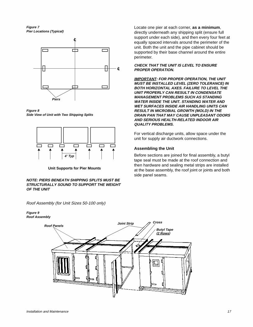
Roof Assembly (for Unit Sizes 50-100 only)
Figure 9Roof Assembly
Piers
C
C
4’ Typ
Unit Supports for Pier Mounts
Butyl Tape
Joint Strip CrossRoof Panels
(2 Rows)
18 CLCH-IM-16A
NOTE: THE BUTYL TAPE APPLIED THE ROOF PANELS WILL COVER THE DRILLED HOLES.
1 Apply butyl tape along four roof panel seams where they come together.
2 Join the panels together at the seams and secure them in place with 5/16 X 3/4” screws and nuts.
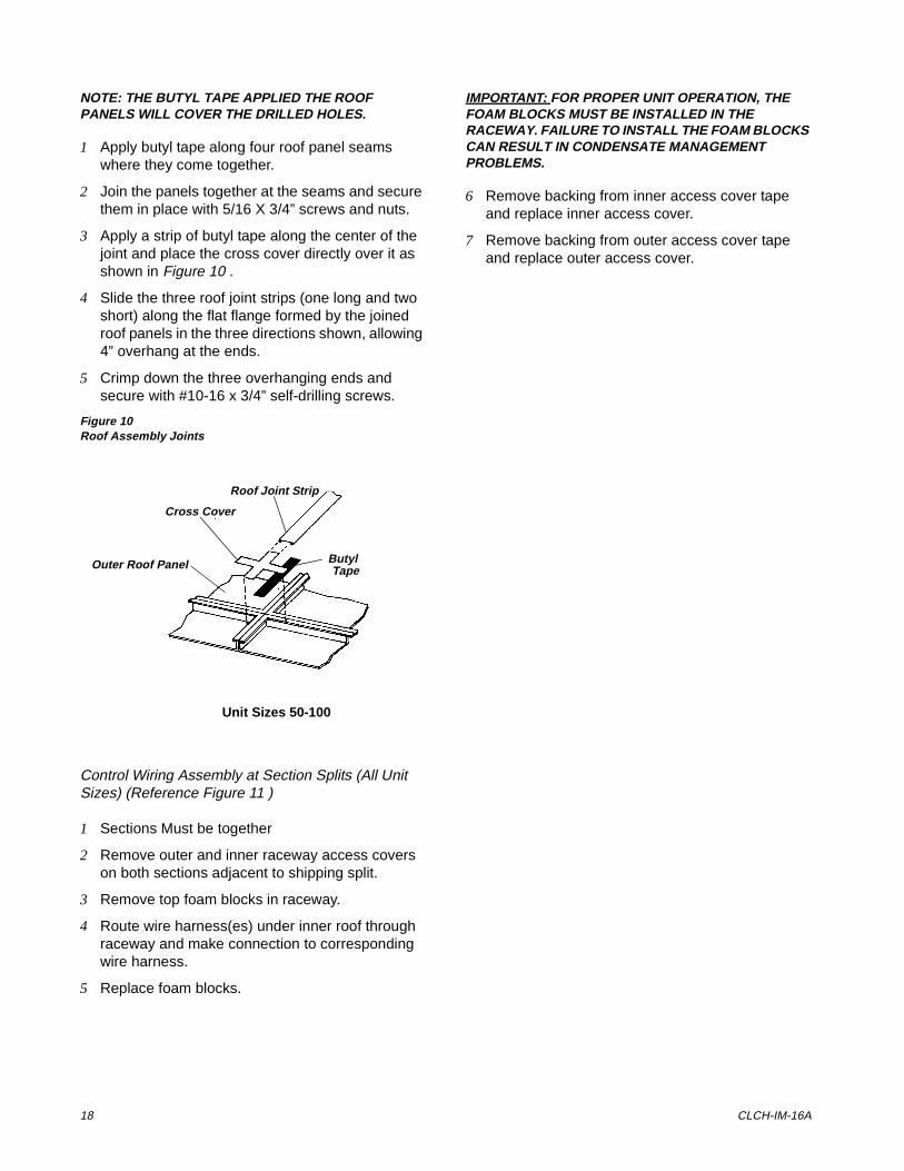
3 Apply a strip of butyl tape along the center of the joint and place the cross cover directly over it as shown in Figure 10 .
4 Slide the three roof joint strips (one long and two short) along the flat flange formed by the joined roof panels in the three directions shown, allowing 4” overhang at the ends.
5 Crimp down the three overhanging ends and secure with #10-16 x 3/4” self-drilling screws.
Figure 10Roof Assembly Joints
Control Wiring Assembly at Section Splits (All Unit Sizes) (Reference Figure 11 )
1 Sections Must be together
2 Remove outer and inner raceway access covers on both sections adjacent to shipping split.
3 Remove top foam blocks in raceway.
4 Route wire harness(es) under inner roof through raceway and make connection to corresponding wire harness.
5 Replace foam blocks.
IMPORTANT: FOR PROPER UNIT OPERATION, THE FOAM BLOCKS MUST BE INSTALLED IN THE RACEWAY. FAILURE TO INSTALL THE FOAM BLOCKS CAN RESULT IN CONDENSATE MANAGEMENT PROBLEMS.
6 Remove backing from inner access cover tape and replace inner access cover.
7 Remove backing from outer access cover tape and replace outer access cover.
Unit Sizes 50-100
Roof Joint Strip
Cross Cover
Outer Roof Panel TapeButyl
Installation and Maintenance 19
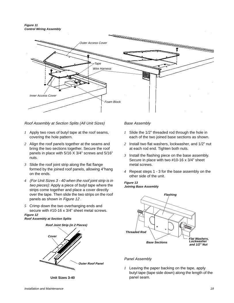
Figure 11Control Wiring Assembly
Roof Assembly at Section Splits (All Unit Sizes)
1 Apply two rows of butyl tape at the roof seams, covering the hole pattern.
2 Align the roof panels together at the seams and bring the two sections together. Secure the roof panels in place with 5/16 X 3/4” screws and 5/16” nuts.
3 Slide the roof joint strip along the flat flange formed by the joined roof panels, allowing 4”hang on the ends.
4 (For Unit Sizes 3 - 40 when the roof joint strip is in two pieces): Apply a piece of butyl tape where the strips come together and place a cover directly over the tape. Then slide the two strips on the roof panels as shown in Figure 12 .
5 Crimp down the two overhanging ends and secure with #10-16 x 3/4” sheet metal screws.
Figure 12Roof Assembly at Section Splits
Base Assembly
1 Slide the 1/2” threaded rod through the hole in each of the two joined base sections as shown.
2 Install two flat washers, lockwasher, and 1/2” nut at each rod end. Tighten both nuts.
3 Install the flashing piece on the base assembly. Secure in place with two #10-16 x 3/4” sheet metal screws.
4 Repeat steps 1 - 3 for the base assembly on the other side of the unit.
Figure 13Joining Base Assembly
Panel Assembly
1 Leaving the paper backing on the tape, apply butyl tape (tape side down) along the length of the panel seam.
Inner Access Cover
Outer Access Cover
Foam Block
Wire Harness
Tape
Outer Roof Panel
Cover
Roof Joint Strip (in 2 Pieces)
Unit Sizes 3-40
Base Sections
Flashing
Threaded Rod
Flat Washers,
and 1/2” NutLockwasher
20 CLCH-IM-16A
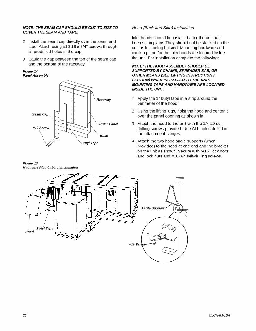
NOTE: THE SEAM CAP SHOULD BE CUT TO SIZE TO COVER THE SEAM AND TAPE.
2 Install the seam cap directly over the seam and tape. Attach using #10-16 x 3/4” screws through all predrilled holes in the cap.
3 Caulk the gap between the top of the seam cap and the bottom of the raceway.
Figure 14Panel Assembly
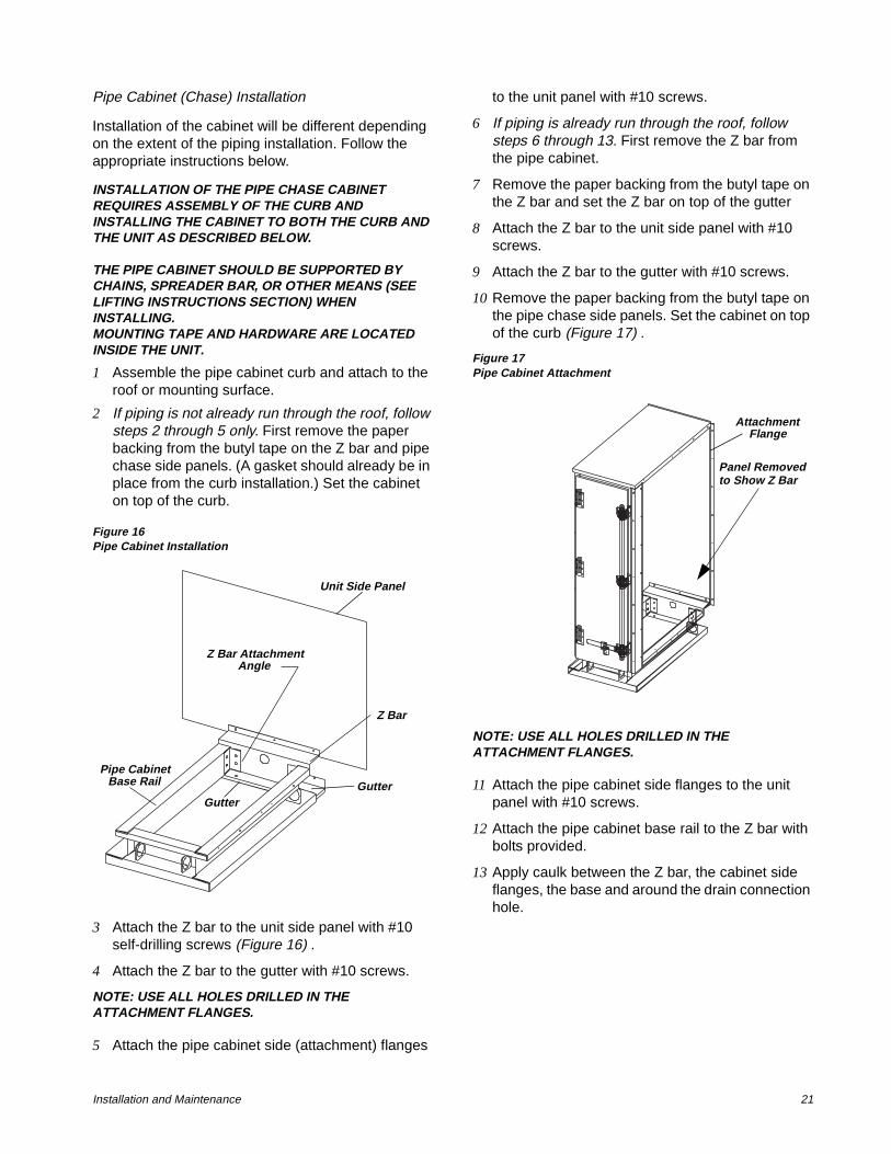
Hood (Back and Side) Installation
Inlet hoods should be installed after the unit has been set in place. They should not be stacked on the unit as it is being hoisted. Mounting hardware and caulking tape for the inlet hoods are located inside the unit. For installation complete the following:
NOTE: THE HOOD ASSEMBLY SHOULD BE SUPPORTED BY CHAINS, SPREADER BAR, OR OTHER MEANS (SEE LIFTING INSTRUCTIONS SECTION) WHEN INSTALLED TO THE UNIT.MOUNTING TAPE AND HARDWARE ARE LOCATED INSIDE THE UNIT.
1 Apply the 1” butyl tape in a strip around the perimeter of the hood.
2 Using the lifting lugs, hoist the hood and center it over the panel opening as shown in.
3 Attach the hood to the unit with the 1/4-20 self-drilling screws provided. Use ALL holes drilled in the attachment flanges.
4 Attach the two hood angle supports (when provided) to the hood at one end and the bracket on the unit as shown. Secure with 5/16” lock bolts and lock nuts and #10-3/4 self-drilling screws.
Figure 15Hood and Pipe Cabinet Installation
Butyl Tape
Raceway
Outer Panel
Base
Seam Cap
#10 Screw
Butyl TapeHood
Angle Support
#10 Screw
Installation and Maintenance 21
Pipe Cabinet (Chase) Installation
Installation of the cabinet will be different depending on the extent of the piping installation. Follow the appropriate instructions below.
INSTALLATION OF THE PIPE CHASE CABINET REQUIRES ASSEMBLY OF THE CURB AND INSTALLING THE CABINET TO BOTH THE CURB AND THE UNIT AS DESCRIBED BELOW.
THE PIPE CABINET SHOULD BE SUPPORTED BY CHAINS, SPREADER BAR, OR OTHER MEANS (SEE LIFTING INSTRUCTIONS SECTION) WHEN INSTALLING.MOUNTING TAPE AND HARDWARE ARE LOCATED INSIDE THE UNIT.
1 Assemble the pipe cabinet curb and attach to the roof or mounting surface.
2 If piping is not already run through the roof, follow steps 2 through 5 only. First remove the paper backing from the butyl tape on the Z bar and pipe chase side panels. (A gasket should already be in place from the curb installation.) Set the cabinet on top of the curb.
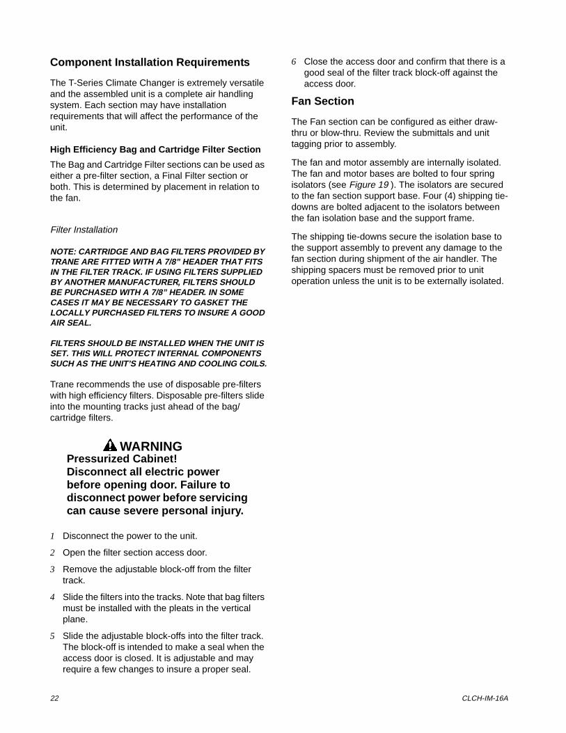
Figure 16Pipe Cabinet Installation
3 Attach the Z bar to the unit side panel with #10 self-drilling screws (Figure 16) .
4 Attach the Z bar to the gutter with #10 screws.
NOTE: USE ALL HOLES DRILLED IN THE ATTACHMENT FLANGES.
5 Attach the pipe cabinet side (attachment) flanges
to the unit panel with #10 screws.
6 If piping is already run through the roof, follow steps 6 through 13. First remove the Z bar from the pipe cabinet.
7 Remove the paper backing from the butyl tape on the Z bar and set the Z bar on top of the gutter
8 Attach the Z bar to the unit side panel with #10 screws.
9 Attach the Z bar to the gutter with #10 screws.
10 Remove the paper backing from the butyl tape on the pipe chase side panels. Set the cabinet on top of the curb (Figure 17) .
Figure 17Pipe Cabinet Attachment
NOTE: USE ALL HOLES DRILLED IN THE ATTACHMENT FLANGES.
11 Attach the pipe cabinet side flanges to the unit panel with #10 screws.
12 Attach the pipe cabinet base rail to the Z bar with bolts provided.
13 Apply caulk between the Z bar, the cabinet side flanges, the base and around the drain connection hole.
Z Bar
Z Bar AttachmentAngle
Pipe CabinetBase Rail Gutter
Gutter
Unit Side Panel
Panel Removedto Show Z Bar
AttachmentFlange
22 CLCH-IM-16A
Component Installation Requirements
The T-Series Climate Changer is extremely versatile and the assembled unit is a complete air handling system. Each section may have installation requirements that will affect the performance of the unit.
High Efficiency Bag and Cartridge Filter Section
The Bag and Cartridge Filter sections can be used as either a pre-filter section, a Final Filter section or both. This is determined by placement in relation to the fan.
Filter Installation
NOTE: CARTRIDGE AND BAG FILTERS PROVIDED BY TRANE ARE FITTED WITH A 7/8” HEADER THAT FITS IN THE FILTER TRACK. IF USING FILTERS SUPPLIED BY ANOTHER MANUFACTURER, FILTERS SHOULD BE PURCHASED WITH A 7/8” HEADER. IN SOME CASES IT MAY BE NECESSARY TO GASKET THE LOCALLY PURCHASED FILTERS TO INSURE A GOOD AIR SEAL.
FILTERS SHOULD BE INSTALLED WHEN THE UNIT IS SET. THIS WILL PROTECT INTERNAL COMPONENTS SUCH AS THE UNIT’S HEATING AND COOLING COILS.
Trane recommends the use of disposable pre-filters with high efficiency filters. Disposable pre-filters slide into the mounting tracks just ahead of the bag/cartridge filters.
WARNINGPressurized Cabinet!Disconnect all electric power before opening door. Failure to disconnect power before servicing can cause severe personal injury.
1 Disconnect the power to the unit.
2 Open the filter section access door.
3 Remove the adjustable block-off from the filter track.
4 Slide the filters into the tracks. Note that bag filters must be installed with the pleats in the vertical plane.
5 Slide the adjustable block-offs into the filter track. The block-off is intended to make a seal when the access door is closed. It is adjustable and may require a few changes to insure a proper seal.
6 Close the access door and confirm that there is a good seal of the filter track block-off against the access door.
Fan Section
The Fan section can be configured as either draw-thru or blow-thru. Review the submittals and unit tagging prior to assembly.
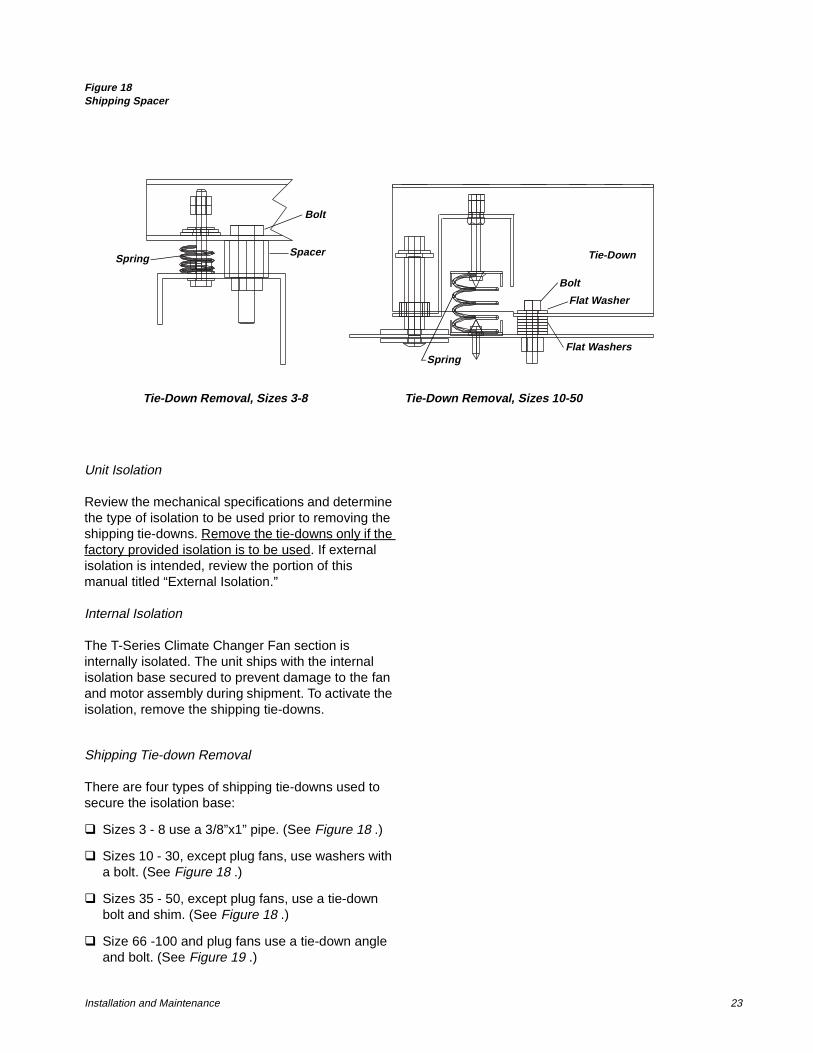
The fan and motor assembly are internally isolated. The fan and motor bases are bolted to four spring isolators (see Figure 19 ). The isolators are secured to the fan section support base. Four (4) shipping tie-downs are bolted adjacent to the isolators between the fan isolation base and the support frame.
The shipping tie-downs secure the isolation base to the support assembly to prevent any damage to the fan section during shipment of the air handler. The shipping spacers must be removed prior to unit operation unless the unit is to be externally isolated.
Installation and Maintenance 23
Figure 18Shipping Spacer
Unit Isolation
Review the mechanical specifications and determine the type of isolation to be used prior to removing the shipping tie-downs. Remove the tie-downs only if the factory provided isolation is to be used. If external isolation is intended, review the portion of this manual titled “External Isolation.”
Internal Isolation
The T-Series Climate Changer Fan section is internally isolated. The unit ships with the internal isolation base secured to prevent damage to the fan and motor assembly during shipment. To activate the isolation, remove the shipping tie-downs.
Shipping Tie-down Removal
There are four types of shipping tie-downs used to secure the isolation base:
q Sizes 3 - 8 use a 3/8”x1” pipe. (See Figure 18 .)
q Sizes 10 - 30, except plug fans, use washers with a bolt. (See Figure 18 .)
q Sizes 35 - 50, except plug fans, use a tie-down bolt and shim. (See Figure 18 .)
q Size 66 -100 and plug fans use a tie-down angle and bolt. (See Figure 19 .)
Tie-Down Removal, Sizes 3-8 Tie-Down Removal, Sizes 10-50
Spring Tie-Down
Flat Washers
Flat Washer
Spring
Bolt
Bolt
Spacer
24 CLCH-IM-16A
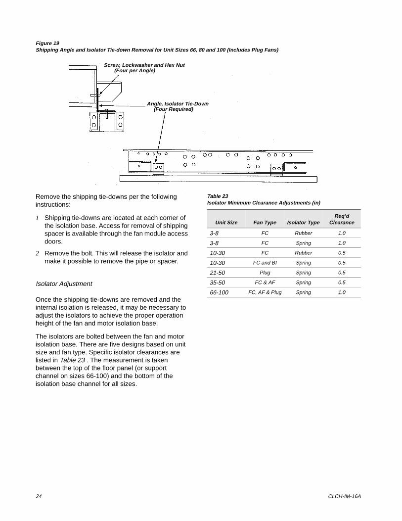
Figure 19Shipping Angle and Isolator Tie-down Removal for Unit Sizes 66, 80 and 100 (Includes Plug Fans)
Remove the shipping tie-downs per the following instructions:
1 Shipping tie-downs are located at each corner of the isolation base. Access for removal of shipping spacer is available through the fan module access doors.
2 Remove the bolt. This will release the isolator and make it possible to remove the pipe or spacer.
Isolator Adjustment
Once the shipping tie-downs are removed and the internal isolation is released, it may be necessary to adjust the isolators to achieve the proper operation height of the fan and motor isolation base.
The isolators are bolted between the fan and motor isolation base. There are five designs based on unit size and fan type. Specific isolator clearances are listed in Table 23 . The measurement is taken between the top of the floor panel (or support channel on sizes 66-100) and the bottom of the isolation base channel for all sizes.
Angle, Isolator Tie-Down(Four Required)
Screw, Lockwasher and Hex Nut(Four per Angle)
Table 23Isolator Minimum Clearance Adjustments (in)
Unit Size Fan Type Isolator TypeReq’d
Clearance
3-8 FC Rubber 1.0
3-8 FC Spring 1.0
10-30 FC Rubber 0.5
10-30 FC and BI Spring 0.5
21-50 Plug Spring 0.5
35-50 FC & AF Spring 0.5
66-100 FC, AF & Plug Spring 1.0
Installation and Maintenance 25
6HW�8S
Once the T-Series Climate Changer is assembled and installed, attention must be directed to individual components for proper operation.
Dampers
(Including filter mixing sections, mixing sections, face and bypass dampers and Traq dampers)
Before installing the Mixing sections fitted with filter racks, be sure adequate clearance is provided to open the access doors and install the filters. Filter installation is explained in the section titled “Filter Installation.”
Figure 20Typical Mixing Box Configuration (sizes 3-100)s
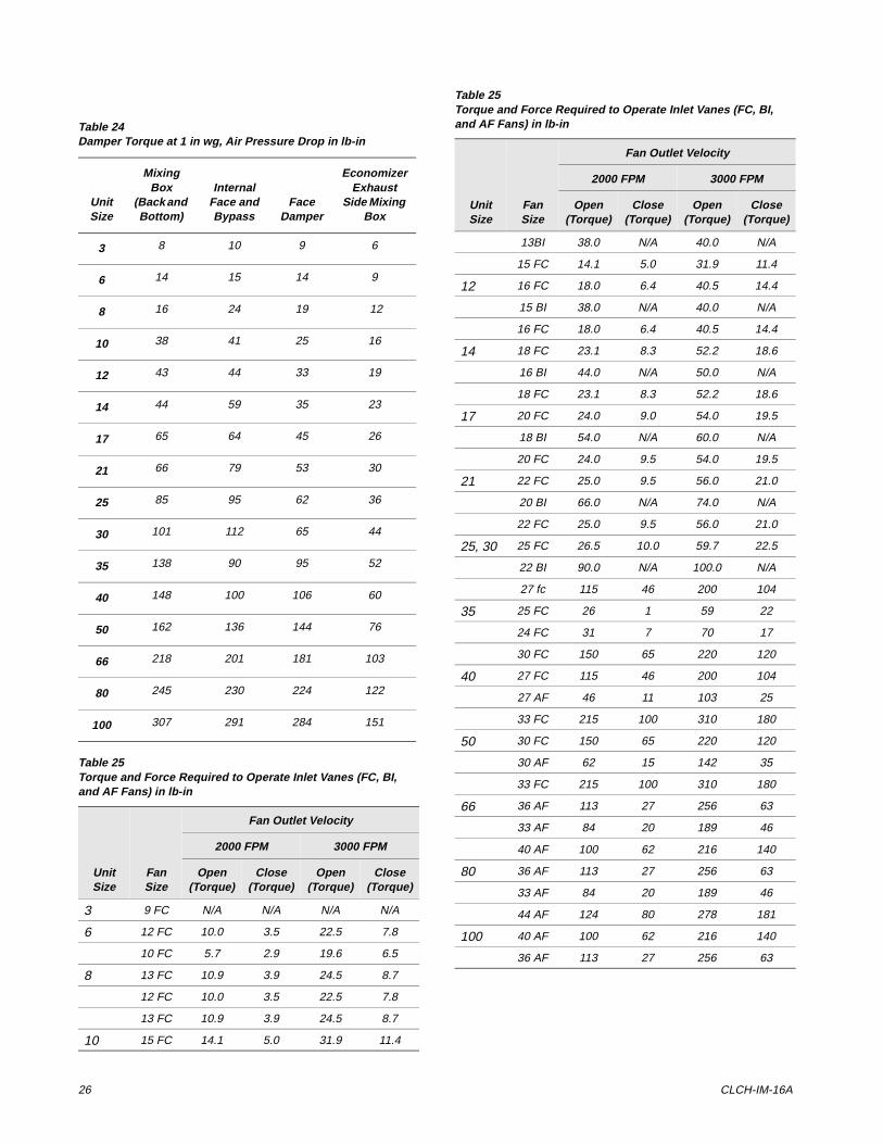
actuators. The actuators should be sized according to the torques given in Table 24 .
NOTE: MIXING SECTIONS, AND FACE AND BYPASS DAMPERS ARE DESIGNED, FOR THE DAMPER ACTUATORS TO BE DIRECT COUPLED AND INSTALLED IN THE AIR STREAM. IF OTHER PROVISIONS ARE REQUIRED, MODIFICATIONS TO THE SECTION WILL BE THE RESPONSIBILITY OF THE INSTALLING CONTRACTOR.
Rods, Operators and Settings
The T-Series Climate Changer is available with factory mounted controls or end devices. If the unit is not ordered with controls or end devices, it is the responsibility of the installer to provide and install the Dampers are factory installed and adjusted. There are three damper blade configurations available: parallel blade, opposed blade, and Traq dampers.
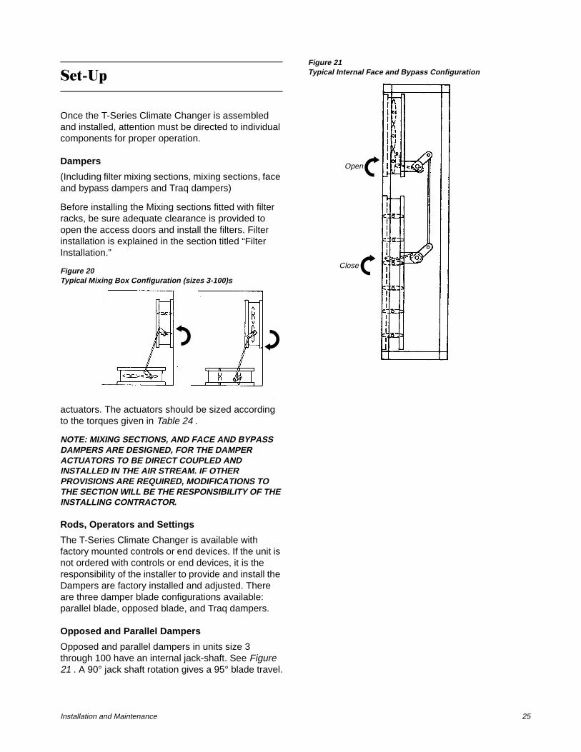
Opposed and Parallel Dampers
Opposed and parallel dampers in units size 3 through 100 have an internal jack-shaft. See Figure 21 . A 90° jack shaft rotation gives a 95° blade travel.
Figure 21Typical Internal Face and Bypass Configuration
Open
Close
26 CLCH-IM-16A
Table 24Damper Torque at 1 in wg, Air Pressure Drop in lb-in
Unit Size
Mixing Box
(Back and Bottom)
Internal Face and Bypass
Face Damper
Economizer Exhaust
Side Mixing Box
3 8 10 9 6
6 14 15 14 9
8 16 24 19 12
10 38 41 25 16
12 43 44 33 19
14 44 59 35 23
17 65 64 45 26
21 66 79 53 30
25 85 95 62 36
30 101 112 65 44
35 138 90 95 52
40 148 100 106 60
50 162 136 144 76
66 218 201 181 103
80 245 230 224 122
100 307 291 284 151
Table 25Torque and Force Required to Operate Inlet Vanes (FC, BI, and AF Fans) in lb-in
Unit Size
Fan Size
Fan Outlet Velocity
2000 FPM 3000 FPM
Open (Torque)
Close (Torque)
Open (Torque)
Close (Torque)
3 9 FC N/A N/A N/A N/A
6 12 FC 10.0 3.5 22.5 7.8
10 FC 5.7 2.9 19.6 6.5
8 13 FC 10.9 3.9 24.5 8.7
12 FC 10.0 3.5 22.5 7.8
13 FC 10.9 3.9 24.5 8.7
10 15 FC 14.1 5.0 31.9 11.4
13BI 38.0 N/A 40.0 N/A
15 FC 14.1 5.0 31.9 11.4
12 16 FC 18.0 6.4 40.5 14.4
15 BI 38.0 N/A 40.0 N/A
16 FC 18.0 6.4 40.5 14.4
14 18 FC 23.1 8.3 52.2 18.6
16 BI 44.0 N/A 50.0 N/A
18 FC 23.1 8.3 52.2 18.6
17 20 FC 24.0 9.0 54.0 19.5
18 BI 54.0 N/A 60.0 N/A
20 FC 24.0 9.5 54.0 19.5
21 22 FC 25.0 9.5 56.0 21.0
20 BI 66.0 N/A 74.0 N/A
22 FC 25.0 9.5 56.0 21.0
25, 30 25 FC 26.5 10.0 59.7 22.5
22 BI 90.0 N/A 100.0 N/A
27 fc 115 46 200 104
35 25 FC 26 1 59 22
24 FC 31 7 70 17
30 FC 150 65 220 120
40 27 FC 115 46 200 104
27 AF 46 11 103 25
33 FC 215 100 310 180
50 30 FC 150 65 220 120
30 AF 62 15 142 35
33 FC 215 100 310 180
66 36 AF 113 27 256 63
33 AF 84 20 189 46
40 AF 100 62 216 140
80 36 AF 113 27 256 63
33 AF 84 20 189 46
44 AF 124 80 278 181
100 40 AF 100 62 216 140
36 AF 113 27 256 63
Table 25Torque and Force Required to Operate Inlet Vanes (FC, BI, and AF Fans) in lb-in
Unit Size
Fan Size
Fan Outlet Velocity
2000 FPM 3000 FPM
Open (Torque)
Close (Torque)
Open (Torque)
Close (Torque)
Installation and Maintenance 27
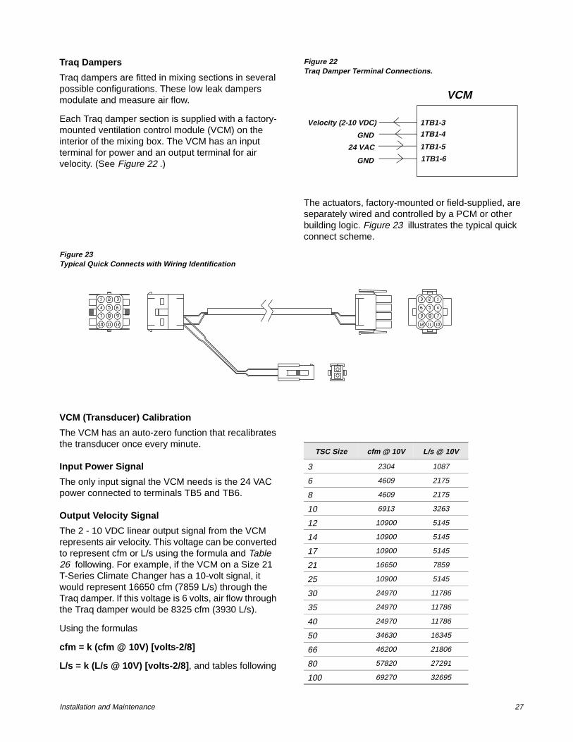
Traq Dampers
Traq dampers are fitted in mixing sections in several possible configurations. These low leak dampers modulate and measure air flow.
Each Traq damper section is supplied with a factory-mounted ventilation control module (VCM) on the interior of the mixing box. The VCM has an input terminal for power and an output terminal for air velocity. (See Figure 22 .)
Figure 22Traq Damper Terminal Connections.
The actuators, factory-mounted or field-supplied, are separately wired and controlled by a PCM or other building logic. Figure 23 illustrates the typical quick connect scheme.
Figure 23Typical Quick Connects with Wiring Identification
VCM (Transducer) Calibration
The VCM has an auto-zero function that recalibrates the transducer once every minute.
Input Power Signal
The only input signal the VCM needs is the 24 VAC power connected to terminals TB5 and TB6.
Output Velocity Signal
The 2 - 10 VDC linear output signal from the VCM represents air velocity. This voltage can be converted to represent cfm or L/s using the formula and Table 26 following. For example, if the VCM on a Size 21 T-Series Climate Changer has a 10-volt signal, it would represent 16650 cfm (7859 L/s) through the Traq damper. If this voltage is 6 volts, air flow through the Traq damper would be 8325 cfm (3930 L/s).
Using the formulas
cfm = k (cfm @ 10V) [volts-2/8]
L/s = k (L/s @ 10V) [volts-2/8], and tables following
VCM
Velocity (2-10 VDC)
GND
24 VAC
GND
1TB1-3
1TB1-4
1TB1-5
1TB1-6
TSC Size cfm @ 10V L/s @ 10V
3 2304 1087
6 4609 2175
8 4609 2175
10 6913 3263
12 10900 5145
14 10900 5145
17 10900 5145
21 16650 7859
25 10900 5145
30 24970 11786
35 24970 11786
40 24970 11786
50 34630 16345
66 46200 21806
80 57820 27291
100 69270 32695
28 CLCH-IM-16A
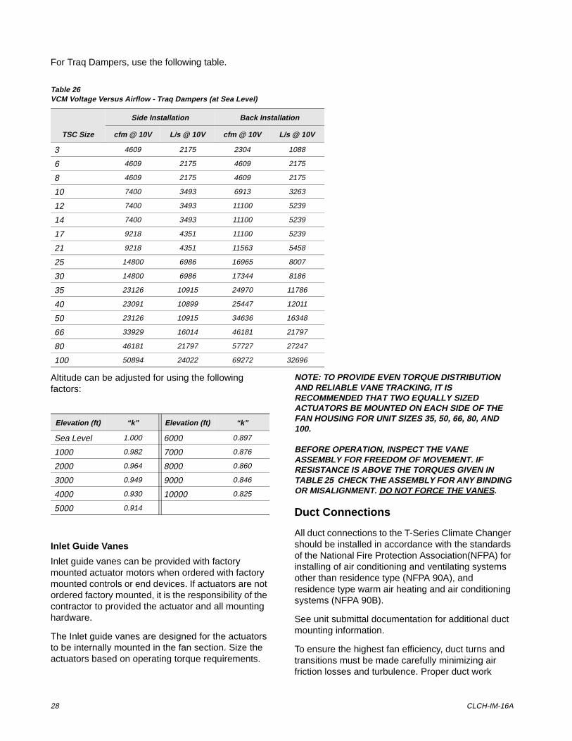
For Traq Dampers, use the following table.
Altitude can be adjusted for using the following factors:
Inlet Guide Vanes
Inlet guide vanes can be provided with factory mounted actuator motors when ordered with factory mounted controls or end devices. If actuators are not ordered factory mounted, it is the responsibility of the contractor to provided the actuator and all mounting hardware.
The Inlet guide vanes are designed for the actuators to be internally mounted in the fan section. Size the actuators based on operating torque requirements.
NOTE: TO PROVIDE EVEN TORQUE DISTRIBUTION AND RELIABLE VANE TRACKING, IT IS RECOMMENDED THAT TWO EQUALLY SIZED ACTUATORS BE MOUNTED ON EACH SIDE OF THE FAN HOUSING FOR UNIT SIZES 35, 50, 66, 80, AND 100.
BEFORE OPERATION, INSPECT THE VANE ASSEMBLY FOR FREEDOM OF MOVEMENT. IF RESISTANCE IS ABOVE THE TORQUES GIVEN IN TABLE 25 CHECK THE ASSEMBLY FOR ANY BINDING OR MISALIGNMENT. DO NOT FORCE THE VANES.
Duct Connections
All duct connections to the T-Series Climate Changer should be installed in accordance with the standards of the National Fire Protection Association(NFPA) for installing of air conditioning and ventilating systems other than residence type (NFPA 90A), and residence type warm air heating and air conditioning systems (NFPA 90B).
See unit submittal documentation for additional duct mounting information.
To ensure the highest fan efficiency, duct turns and transitions must be made carefully minimizing air friction losses and turbulence. Proper duct work
Table 26VCM Voltage Versus Airflow - Traq Dampers (at Sea Level)
TSC Size
Side Installation Back Installation
cfm @ 10V L/s @ 10V cfm @ 10V L/s @ 10V
3 4609 2175 2304 1088
6 4609 2175 4609 2175
8 4609 2175 4609 2175
10 7400 3493 6913 3263
12 7400 3493 11100 5239
14 7400 3493 11100 5239
17 9218 4351 11100 5239
21 9218 4351 11563 5458
25 14800 6986 16965 8007
30 14800 6986 17344 8186
35 23126 10915 24970 11786
40 23091 10899 25447 12011
50 23126 10915 34636 16348
66 33929 16014 46181 21797
80 46181 21797 57727 27247
100 50894 24022 69272 32696
Elevation (ft) “k” Elevation (ft) “k”
Sea Level 1.000 6000 0.897
1000 0.982 7000 0.876
2000 0.964 8000 0.860
3000 0.949 9000 0.846
4000 0.930 10000 0.825
5000 0.914
Installation and Maintenance 29
installation, as outlined by such organizations as SMACNA (Sheet Metal and Air Conditioning Contractors National Association, Inc.) should be adhered to.
Fan Discharge Connections
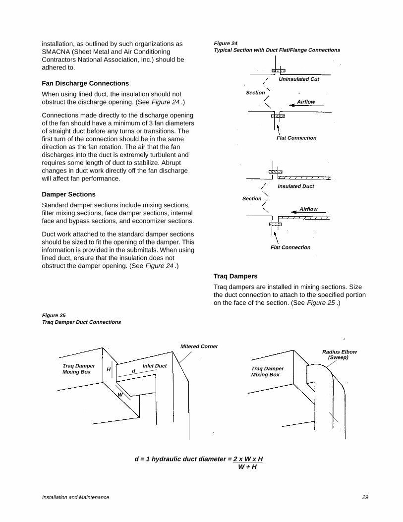
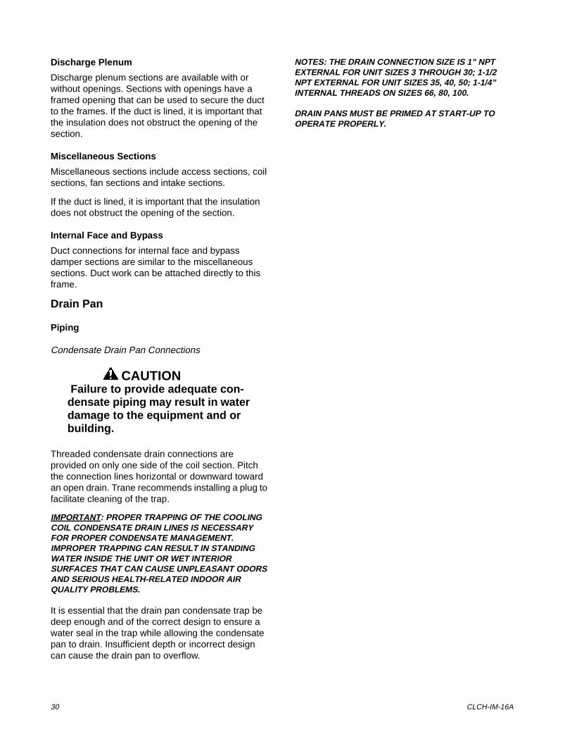
When using lined duct, the insulation should not obstruct the discharge opening. (See Figure 24 .)
Connections made directly to the discharge opening of the fan should have a minimum of 3 fan diameters of straight duct before any turns or transitions. The first turn of the connection should be in the same direction as the fan rotation. The air that the fan discharges into the duct is extremely turbulent and requires some length of duct to stabilize. Abrupt changes in duct work directly off the fan discharge will affect fan performance.
Damper Sections
Standard damper sections include mixing sections, filter mixing sections, face damper sections, internal face and bypass sections, and economizer sections.
Duct work attached to the standard damper sections should be sized to fit the opening of the damper. This information is provided in the submittals. When using lined duct, ensure that the insulation does not obstruct the damper opening. (See Figure 24 .)
Figure 24Typical Section with Duct Flat/Flange Connections
Traq Dampers
Traq dampers are installed in mixing sections. Size the duct connection to attach to the specified portion on the face of the section. (See Figure 25 .)
Figure 25Traq Damper Duct Connections
Uninsulated Cut
Airflow
Section
Flat Connection
Insulated Duct
Section
Flat Connection
Airflow
Traq DamperMixing Box
W
H dInlet Duct
Radius Elbow(Sweep)
Traq DamperMixing Box
d = 1 hydraulic duct diameter = 2 x W x H________W + H
Mitered Corner
30 CLCH-IM-16A
Discharge Plenum
Discharge plenum sections are available with or without openings. Sections with openings have a framed opening that can be used to secure the duct to the frames. If the duct is lined, it is important that the insulation does not obstruct the opening of the section.
Miscellaneous Sections
Miscellaneous sections include access sections, coil sections, fan sections and intake sections.
If the duct is lined, it is important that the insulation does not obstruct the opening of the section.
Internal Face and Bypass
Duct connections for internal face and bypass damper sections are similar to the miscellaneous sections. Duct work can be attached directly to this frame.
Drain Pan
Piping
Condensate Drain Pan Connections
CAUTION Failure to provide adequate con-densate piping may result in water damage to the equipment and or building.
Threaded condensate drain connections are provided on only one side of the coil section. Pitch the connection lines horizontal or downward toward an open drain. Trane recommends installing a plug to facilitate cleaning of the trap.
IMPORTANT: PROPER TRAPPING OF THE COOLING COIL CONDENSATE DRAIN LINES IS NECESSARY FOR PROPER CONDENSATE MANAGEMENT. IMPROPER TRAPPING CAN RESULT IN STANDING WATER INSIDE THE UNIT OR WET INTERIOR SURFACES THAT CAN CAUSE UNPLEASANT ODORS AND SERIOUS HEALTH-RELATED INDOOR AIR QUALITY PROBLEMS.
It is essential that the drain pan condensate trap be deep enough and of the correct design to ensure a water seal in the trap while allowing the condensate pan to drain. Insufficient depth or incorrect design can cause the drain pan to overflow.
NOTES: THE DRAIN CONNECTION SIZE IS 1” NPT EXTERNAL FOR UNIT SIZES 3 THROUGH 30; 1-1/2 NPT EXTERNAL FOR UNIT SIZES 35, 40, 50; 1-1/4” INTERNAL THREADS ON SIZES 66, 80, 100.
DRAIN PANS MUST BE PRIMED AT START-UP TO OPERATE PROPERLY.
Installation and Maintenance 31
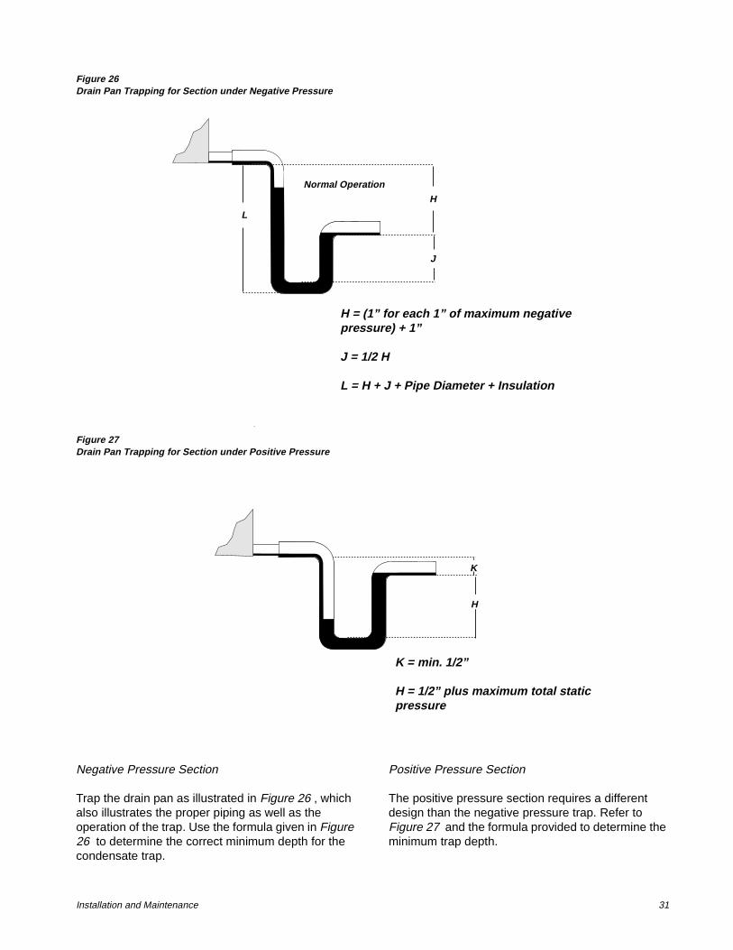
Figure 26Drain Pan Trapping for Section under Negative Pressure
Figure 27Drain Pan Trapping for Section under Positive Pressure
Negative Pressure Section
Trap the drain pan as illustrated in Figure 26 , which also illustrates the proper piping as well as the operation of the trap. Use the formula given in Figure 26 to determine the correct minimum depth for the condensate trap.
Positive Pressure Section
The positive pressure section requires a different design than the negative pressure trap. Refer to Figure 27 and the formula provided to determine the minimum trap depth.
3C - Normal Operation
LH
J
H= (1" for each 1" of maximum negative static pressure) + 1"
J= half of H
L= H + J + Pipe Diameter + Insulation
H = (1” for each 1” of maximum negative pressure) + 1”
J = 1/2 H
L = H + J + Pipe Diameter + Insulation
Normal Operation
H
J
L
K
2C - Normal Operation
H
K= min. 1/2"
H= 1/2" plus maximum
total static pressure
K = min. 1/2”
H = 1/2” plus maximum total static pressure
K
H
32 CLCH-IM-16A
Units With More Than One Drain Pan
With the T-Series Climate Changer, each section can be ordered with or without a drain pan. When more than one section has a drain pan, you must trap each section individually. Connecting all drains to a common line with only one trap will result in condensate retention, and possible water damage to the air handler or adjoining space.
If a section has a drain pan for cleaning purposes only, it does not need a trap; however a cap or shut off valve should be installed on the drain connection. Only sections handling condensate, such as a cooling coil section or eliminator section, require a trap. Figure 28 through Figure 37 are examples of typical installations.
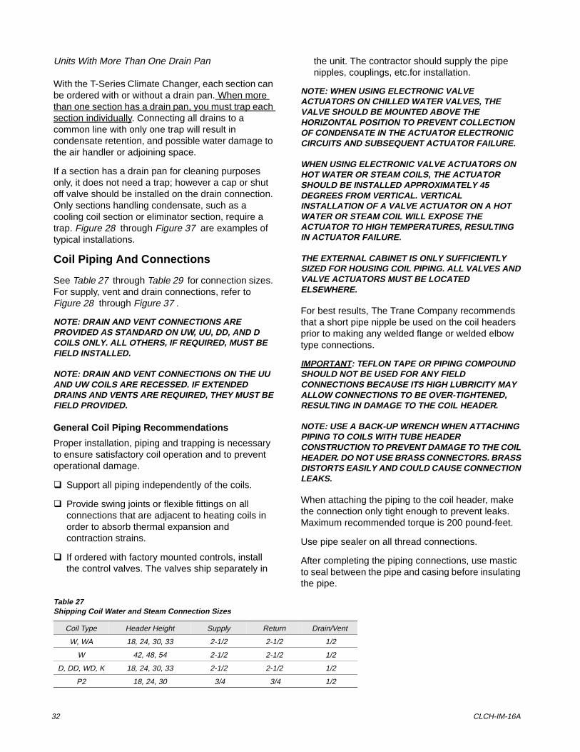
Coil Piping And Connections
See Table 27 through Table 29 for connection sizes. For supply, vent and drain connections, refer to Figure 28 through Figure 37 .
NOTE: DRAIN AND VENT CONNECTIONS ARE PROVIDED AS STANDARD ON UW, UU, DD, AND D COILS ONLY. ALL OTHERS, IF REQUIRED, MUST BE FIELD INSTALLED.
NOTE: DRAIN AND VENT CONNECTIONS ON THE UU AND UW COILS ARE RECESSED. IF EXTENDED DRAINS AND VENTS ARE REQUIRED, THEY MUST BE FIELD PROVIDED.
General Coil Piping Recommendations
Proper installation, piping and trapping is necessary to ensure satisfactory coil operation and to prevent operational damage.
q Support all piping independently of the coils.
q Provide swing joints or flexible fittings on all connections that are adjacent to heating coils in order to absorb thermal expansion and contraction strains.
q If ordered with factory mounted controls, install the control valves. The valves ship separately in
the unit. The contractor should supply the pipe nipples, couplings, etc.for installation.
NOTE: WHEN USING ELECTRONIC VALVE ACTUATORS ON CHILLED WATER VALVES, THE VALVE SHOULD BE MOUNTED ABOVE THE HORIZONTAL POSITION TO PREVENT COLLECTION OF CONDENSATE IN THE ACTUATOR ELECTRONIC CIRCUITS AND SUBSEQUENT ACTUATOR FAILURE.
WHEN USING ELECTRONIC VALVE ACTUATORS ON HOT WATER OR STEAM COILS, THE ACTUATOR SHOULD BE INSTALLED APPROXIMATELY 45 DEGREES FROM VERTICAL. VERTICAL INSTALLATION OF A VALVE ACTUATOR ON A HOT WATER OR STEAM COIL WILL EXPOSE THE ACTUATOR TO HIGH TEMPERATURES, RESULTING IN ACTUATOR FAILURE.
THE EXTERNAL CABINET IS ONLY SUFFICIENTLY SIZED FOR HOUSING COIL PIPING. ALL VALVES AND VALVE ACTUATORS MUST BE LOCATED ELSEWHERE.
For best results, The Trane Company recommends that a short pipe nipple be used on the coil headers prior to making any welded flange or welded elbow type connections.
IMPORTANT: TEFLON TAPE OR PIPING COMPOUND SHOULD NOT BE USED FOR ANY FIELD CONNECTIONS BECAUSE ITS HIGH LUBRICITY MAY ALLOW CONNECTIONS TO BE OVER-TIGHTENED, RESULTING IN DAMAGE TO THE COIL HEADER.
NOTE: USE A BACK-UP WRENCH WHEN ATTACHING PIPING TO COILS WITH TUBE HEADER CONSTRUCTION TO PREVENT DAMAGE TO THE COIL HEADER. DO NOT USE BRASS CONNECTORS. BRASS DISTORTS EASILY AND COULD CAUSE CONNECTION LEAKS.
When attaching the piping to the coil header, make the connection only tight enough to prevent leaks. Maximum recommended torque is 200 pound-feet.
Use pipe sealer on all thread connections.
After completing the piping connections, use mastic to seal between the pipe and casing before insulating the pipe.
Table 27Shipping Coil Water and Steam Connection Sizes
Coil Type Header Height Supply Return Drain/Vent
W, WA 18, 24, 30, 33 2-1/2 2-1/2 1/2
W 42, 48, 54 2-1/2 2-1/2 1/2
D, DD, WD, K 18, 24, 30, 33 2-1/2 2-1/2 1/2
P2 18, 24, 30 3/4 3/4 1/2
Installation and Maintenance 33
P4 18, 24, 30 1 1 1/2
P8 18, 24, 30 1-1/4 1-1/4 1/2
WC 18 1 1 1/2
WC 24 1-1/4 1-1/4 1/2
WC 30, 33 2-1/2 1-1/2 1/2
NS 18 2 1 1
NS 24 2-1/2 1-1/4 1-1/4
NS 30, 33 3 1-1/4 1-1/4
Table 27Shipping Coil Water and Steam Connection Sizes
Coil Type Header Height Supply Return Drain/Vent
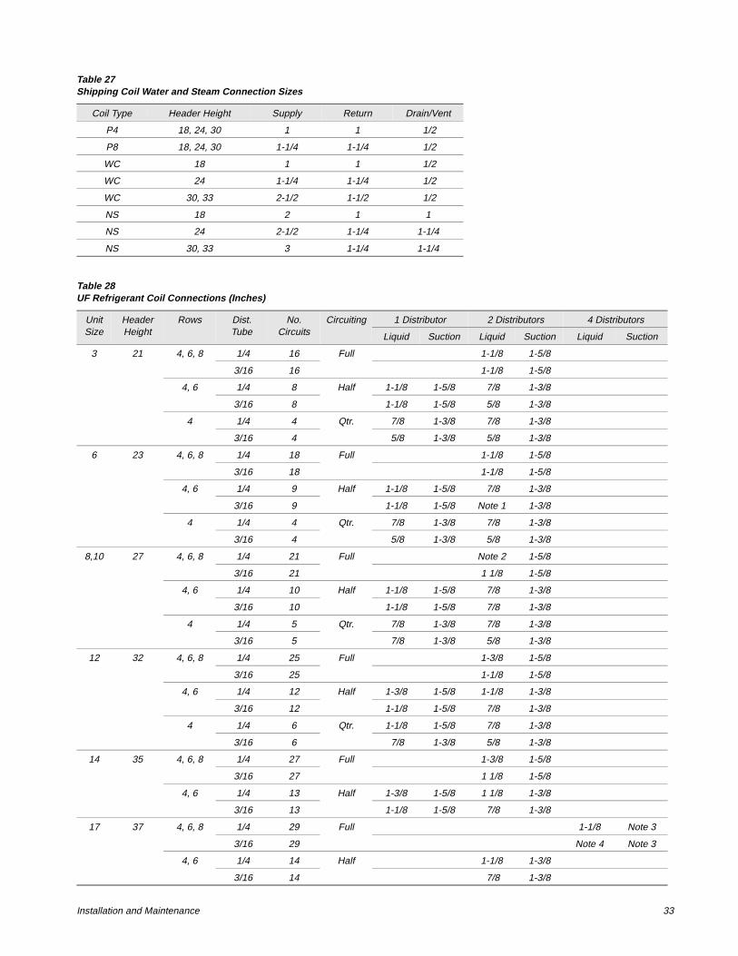
Table 28UF Refrigerant Coil Connections (Inches)
UnitSize
HeaderHeight
Rows Dist.Tube
No.Circuits
Circuiting 1 Distributor 2 Distributors 4 Distributors
Liquid Suction Liquid Suction Liquid Suction
3 21 4, 6, 8 1/4 16 Full 1-1/8 1-5/8
3/16 16 1-1/8 1-5/8
4, 6 1/4 8 Half 1-1/8 1-5/8 7/8 1-3/8
3/16 8 1-1/8 1-5/8 5/8 1-3/8
4 1/4 4 Qtr. 7/8 1-3/8 7/8 1-3/8
3/16 4 5/8 1-3/8 5/8 1-3/8
6 23 4, 6, 8 1/4 18 Full 1-1/8 1-5/8
3/16 18 1-1/8 1-5/8
4, 6 1/4 9 Half 1-1/8 1-5/8 7/8 1-3/8
3/16 9 1-1/8 1-5/8 Note 1 1-3/8
4 1/4 4 Qtr. 7/8 1-3/8 7/8 1-3/8
3/16 4 5/8 1-3/8 5/8 1-3/8
8,10 27 4, 6, 8 1/4 21 Full Note 2 1-5/8
3/16 21 1 1/8 1-5/8
4, 6 1/4 10 Half 1-1/8 1-5/8 7/8 1-3/8
3/16 10 1-1/8 1-5/8 7/8 1-3/8
4 1/4 5 Qtr. 7/8 1-3/8 7/8 1-3/8
3/16 5 7/8 1-3/8 5/8 1-3/8
12 32 4, 6, 8 1/4 25 Full 1-3/8 1-5/8
3/16 25 1-1/8 1-5/8
4, 6 1/4 12 Half 1-3/8 1-5/8 1-1/8 1-3/8
3/16 12 1-1/8 1-5/8 7/8 1-3/8
4 1/4 6 Qtr. 1-1/8 1-5/8 7/8 1-3/8
3/16 6 7/8 1-3/8 5/8 1-3/8
14 35 4, 6, 8 1/4 27 Full 1-3/8 1-5/8
3/16 27 1 1/8 1-5/8
4, 6 1/4 13 Half 1-3/8 1-5/8 1 1/8 1-3/8
3/16 13 1-1/8 1-5/8 7/8 1-3/8
17 37 4, 6, 8 1/4 29 Full 1-1/8 Note 3
3/16 29 Note 4 Note 3
4, 6 1/4 14 Half 1-1/8 1-3/8
3/16 14 7/8 1-3/8
34 CLCH-IM-16A
Notes:
Number of connections - Size (Inches)
1. 1- 5/8, 1- 7/8
2. 1-1 1/8 and 1-1 3/8
3. 3-1 3/8 and 1-1 5/8
4. 3-7/8 and 1-1 1/8
5. 3-5/8 and 1-7/8
Notes:
Number of connections - Size (Inches):
1. 2-7/8, 2-1-1/8
2. 6-1 3/8 and 2-1-5/8
3. 6-7/8 and 2-1-1/8
4. 6-5/8 and 2-7/8
21 45 4, 6, 8 1/4 35 Full 1-1/8 1-5/8
3/16 35 1-1/8 1-5/8
4, 6 1/4 17 Half 1-1/8 1-5/8 7/8 1-3/8
3/16 17 1-1/8 1-5/8 Note 5 1-3/8
25,30 51 4, 6, 8 1/4 40 Full 1-1/8 1-5/8
3/16 40 1 1/8 1-5/8
4, 6 1/4 20 Half 1-1/8 1-5/8 7/8 1-3/8
3/16 20 1-1/8 1-5/8 7/8 1-3/8
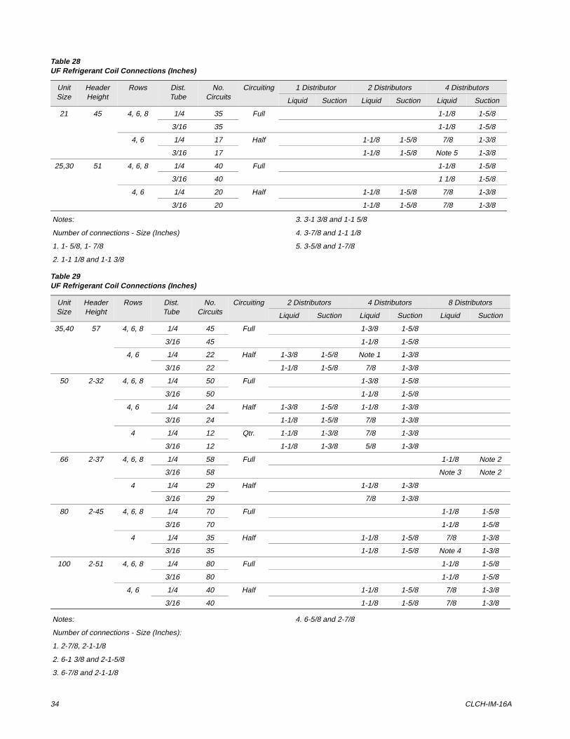
Table 28UF Refrigerant Coil Connections (Inches)
UnitSize
HeaderHeight
Rows Dist.Tube
No.Circuits
Circuiting 1 Distributor 2 Distributors 4 Distributors
Liquid Suction Liquid Suction Liquid Suction
Table 29UF Refrigerant Coil Connections (Inches)
Unit Size
Header Height
Rows Dist. Tube
No. Circuits
Circuiting 2 Distributors 4 Distributors 8 Distributors
Liquid Suction Liquid Suction Liquid Suction
35,40 57 4, 6, 8 1/4 45 Full 1-3/8 1-5/8
3/16 45 1-1/8 1-5/8
4, 6 1/4 22 Half 1-3/8 1-5/8 Note 1 1-3/8
3/16 22 1-1/8 1-5/8 7/8 1-3/8
50 2-32 4, 6, 8 1/4 50 Full 1-3/8 1-5/8
3/16 50 1-1/8 1-5/8
4, 6 1/4 24 Half 1-3/8 1-5/8 1-1/8 1-3/8
3/16 24 1-1/8 1-5/8 7/8 1-3/8
4 1/4 12 Qtr. 1-1/8 1-3/8 7/8 1-3/8
3/16 12 1-1/8 1-3/8 5/8 1-3/8
66 2-37 4, 6, 8 1/4 58 Full 1-1/8 Note 2
3/16 58 Note 3 Note 2
4 1/4 29 Half 1-1/8 1-3/8
3/16 29 7/8 1-3/8
80 2-45 4, 6, 8 1/4 70 Full 1-1/8 1-5/8
3/16 70 1-1/8 1-5/8
4 1/4 35 Half 1-1/8 1-5/8 7/8 1-3/8
3/16 35 1-1/8 1-5/8 Note 4 1-3/8
100 2-51 4, 6, 8 1/4 80 Full 1-1/8 1-5/8
3/16 80 1-1/8 1-5/8
4, 6 1/4 40 Half 1-1/8 1-5/8 7/8 1-3/8
3/16 40 1-1/8 1-5/8 7/8 1-3/8
Installation and Maintenance 35
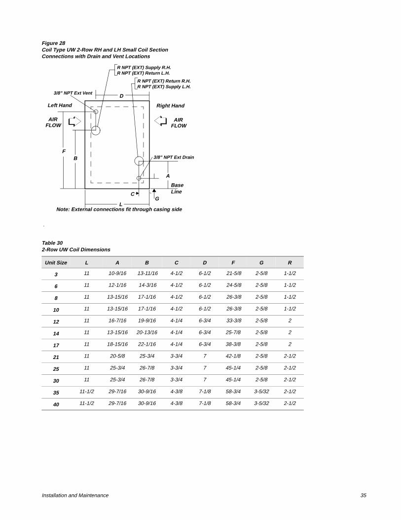
Figure 28Coil Type UW 2-Row RH and LH Small Coil Section Connections with Drain and Vent Locations
.
BaseLine
Left Hand Right Hand
AIRFLOW
AIRFLOW
A
B
C
D
F
GL
3/8” NPT Ext Drain
3/8” NPT Ext Vent
R NPT (EXT) Return R.H.R NPT (EXT) Supply L.H.
R NPT (EXT) Supply R.H.R NPT (EXT) Return L.H.
Note: External connections fit through casing side
Table 302-Row UW Coil Dimensions
Unit Size L A B C D F G R
3 11 10-9/16 13-11/16 4-1/2 6-1/2 21-5/8 2-5/8 1-1/2
6 11 12-1/16 14-3/16 4-1/2 6-1/2 24-5/8 2-5/8 1-1/2
8 11 13-15/16 17-1/16 4-1/2 6-1/2 26-3/8 2-5/8 1-1/2
10 11 13-15/16 17-1/16 4-1/2 6-1/2 26-3/8 2-5/8 1-1/2
12 11 16-7/16 19-9/16 4-1/4 6-3/4 33-3/8 2-5/8 2
14 11 13-15/16 20-13/16 4-1/4 6-3/4 25-7/8 2-5/8 2
17 11 18-15/16 22-1/16 4-1/4 6-3/4 38-3/8 2-5/8 2
21 11 20-5/8 25-3/4 3-3/4 7 42-1/8 2-5/8 2-1/2
25 11 25-3/4 26-7/8 3-3/4 7 45-1/4 2-5/8 2-1/2
30 11 25-3/4 26-7/8 3-3/4 7 45-1/4 2-5/8 2-1/2
35 11-1/2 29-7/16 30-9/16 4-3/8 7-1/8 58-3/4 3-5/32 2-1/2
40 11-1/2 29-7/16 30-9/16 4-3/8 7-1/8 58-3/4 3-5/32 2-1/2
36 CLCH-IM-16A
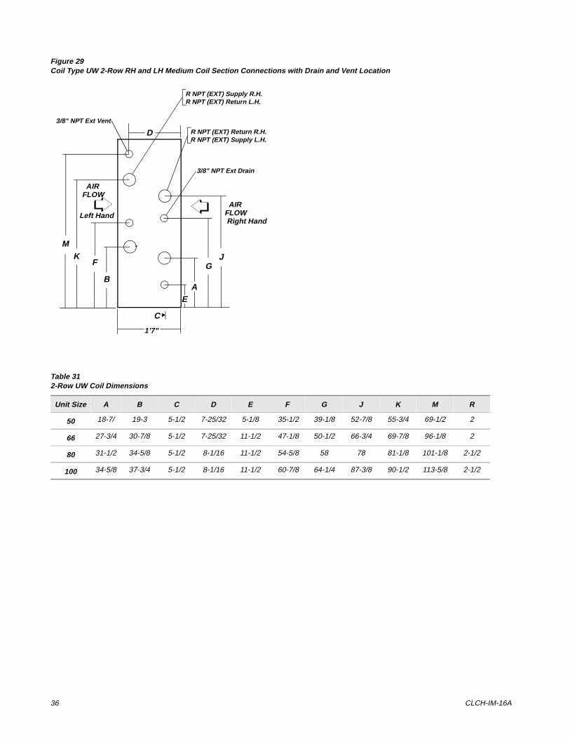
Figure 29Coil Type UW 2-Row RH and LH Medium Coil Section Connections with Drain and Vent Location
Table 312-Row UW Coil Dimensions
Unit Size A B C D E F G J K M R
50 18-7/ 19-3 5-1/2 7-25/32 5-1/8 35-1/2 39-1/8 52-7/8 55-3/4 69-1/2 2
66 27-3/4 30-7/8 5-1/2 7-25/32 11-1/2 47-1/8 50-1/2 66-3/4 69-7/8 96-1/8 2
80 31-1/2 34-5/8 5-1/2 8-1/16 11-1/2 54-5/8 58 78 81-1/8 101-1/8 2-1/2
100 34-5/8 37-3/4 5-1/2 8-1/16 11-1/2 60-7/8 64-1/4 87-3/8 90-1/2 113-5/8 2-1/2
AIRFLOW
AIRFLOW
AB
C
D
E
F GJK
M
1’7”
R NPT (EXT) Supply R.H.R NPT (EXT) Return L.H.
R NPT (EXT) Return R.H.R NPT (EXT) Supply L.H.
3/8” NPT Ext Vent
3/8” NPT Ext Drain
Left HandRight Hand
Installation and Maintenance 37
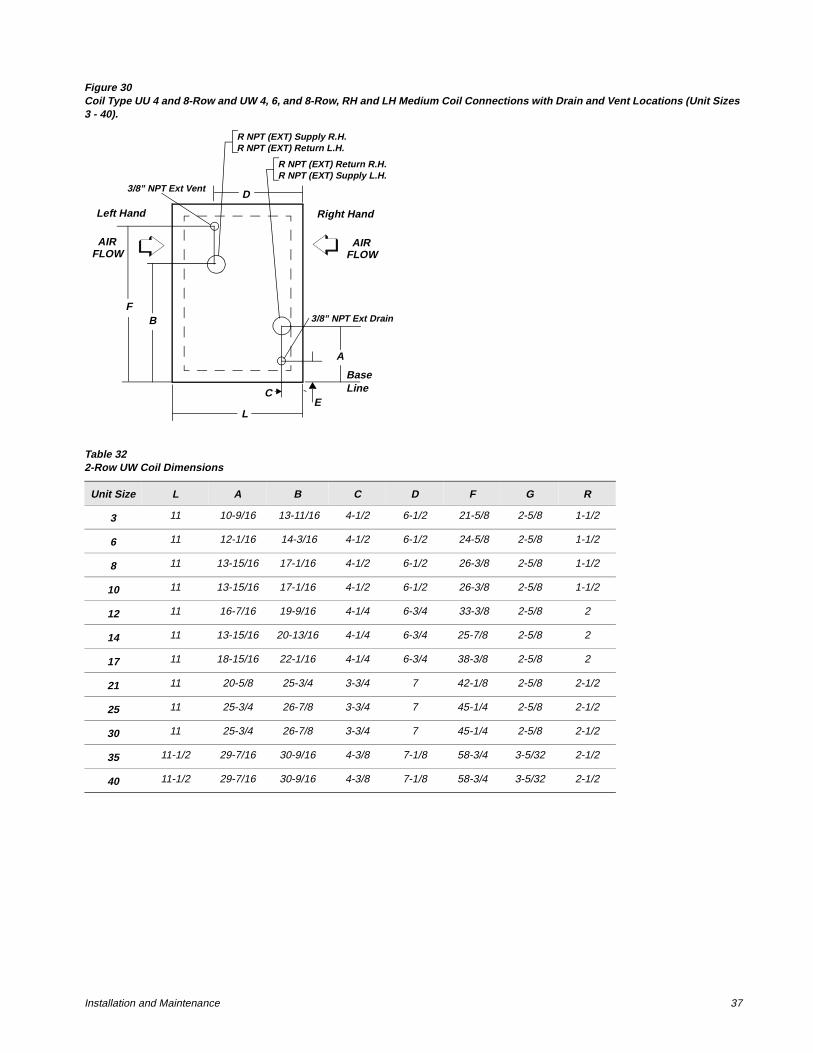
Figure 30Coil Type UU 4 and 8-Row and UW 4, 6, and 8-Row, RH and LH Medium Coil Connections with Drain and Vent Locations (Unit Sizes 3 - 40).
Table 322-Row UW Coil Dimensions
Unit Size L A B C D F G R
3 11 10-9/16 13-11/16 4-1/2 6-1/2 21-5/8 2-5/8 1-1/2
6 11 12-1/16 14-3/16 4-1/2 6-1/2 24-5/8 2-5/8 1-1/2
8 11 13-15/16 17-1/16 4-1/2 6-1/2 26-3/8 2-5/8 1-1/2
10 11 13-15/16 17-1/16 4-1/2 6-1/2 26-3/8 2-5/8 1-1/2
12 11 16-7/16 19-9/16 4-1/4 6-3/4 33-3/8 2-5/8 2
14 11 13-15/16 20-13/16 4-1/4 6-3/4 25-7/8 2-5/8 2
17 11 18-15/16 22-1/16 4-1/4 6-3/4 38-3/8 2-5/8 2
21 11 20-5/8 25-3/4 3-3/4 7 42-1/8 2-5/8 2-1/2
25 11 25-3/4 26-7/8 3-3/4 7 45-1/4 2-5/8 2-1/2
30 11 25-3/4 26-7/8 3-3/4 7 45-1/4 2-5/8 2-1/2
35 11-1/2 29-7/16 30-9/16 4-3/8 7-1/8 58-3/4 3-5/32 2-1/2
40 11-1/2 29-7/16 30-9/16 4-3/8 7-1/8 58-3/4 3-5/32 2-1/2
BaseLine
Left Hand Right Hand
AIRFLOW
AIRFLOW
A
B
C
D
F
EL
3/8” NPT Ext Drain
3/8” NPT Ext Vent
R NPT (EXT) Return R.H.R NPT (EXT) Supply L.H.
R NPT (EXT) Supply R.H.R NPT (EXT) Return L.H.
38 CLCH-IM-16A
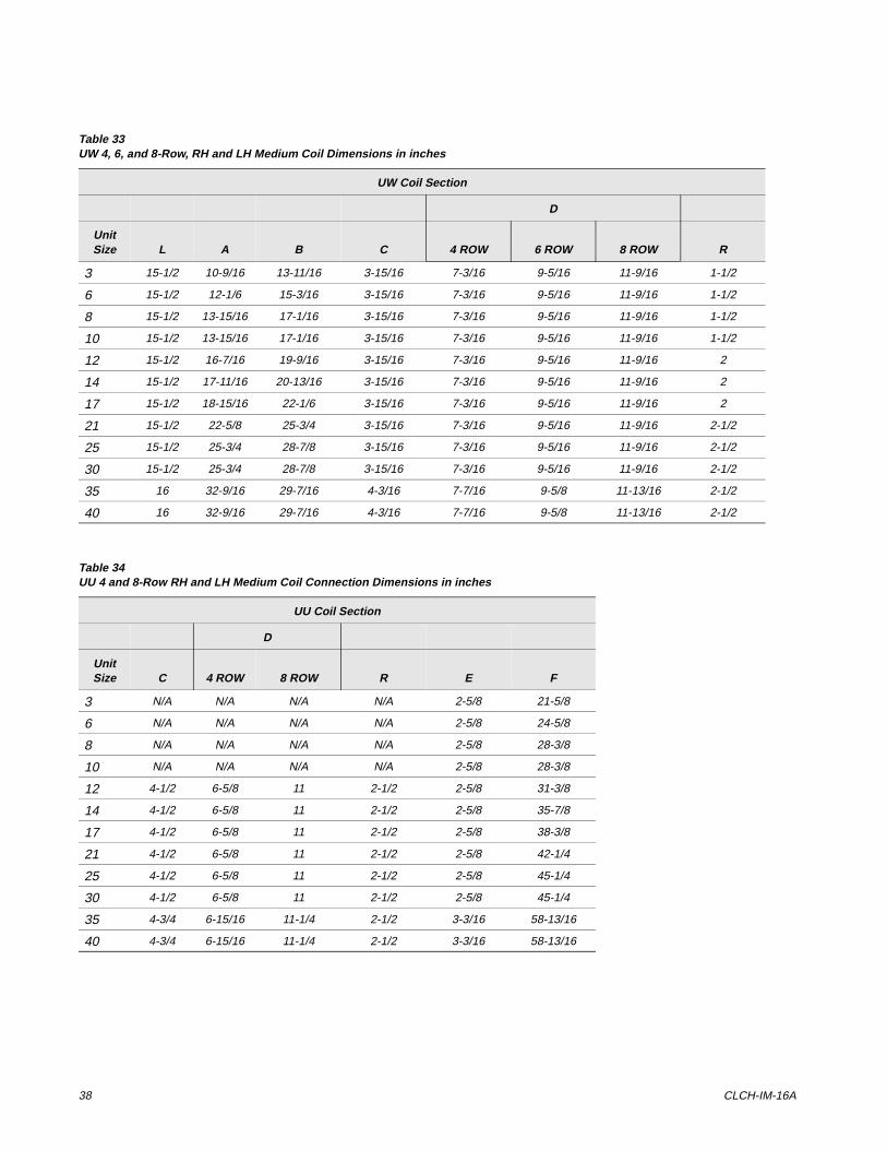
Table 33UW 4, 6, and 8-Row, RH and LH Medium Coil Dimensions in inches
UW Coil Section
D
Unit Size L A B C 4 ROW 6 ROW 8 ROW R
3 15-1/2 10-9/16 13-11/16 3-15/16 7-3/16 9-5/16 11-9/16 1-1/2
6 15-1/2 12-1/6 15-3/16 3-15/16 7-3/16 9-5/16 11-9/16 1-1/2
8 15-1/2 13-15/16 17-1/16 3-15/16 7-3/16 9-5/16 11-9/16 1-1/2
10 15-1/2 13-15/16 17-1/16 3-15/16 7-3/16 9-5/16 11-9/16 1-1/2
12 15-1/2 16-7/16 19-9/16 3-15/16 7-3/16 9-5/16 11-9/16 2
14 15-1/2 17-11/16 20-13/16 3-15/16 7-3/16 9-5/16 11-9/16 2
17 15-1/2 18-15/16 22-1/6 3-15/16 7-3/16 9-5/16 11-9/16 2
21 15-1/2 22-5/8 25-3/4 3-15/16 7-3/16 9-5/16 11-9/16 2-1/2
25 15-1/2 25-3/4 28-7/8 3-15/16 7-3/16 9-5/16 11-9/16 2-1/2
30 15-1/2 25-3/4 28-7/8 3-15/16 7-3/16 9-5/16 11-9/16 2-1/2
35 16 32-9/16 29-7/16 4-3/16 7-7/16 9-5/8 11-13/16 2-1/2
40 16 32-9/16 29-7/16 4-3/16 7-7/16 9-5/8 11-13/16 2-1/2
Table 34UU 4 and 8-Row RH and LH Medium Coil Connection Dimensions in inches
UU Coil Section
D
Unit Size C 4 ROW 8 ROW R E F
3 N/A N/A N/A N/A 2-5/8 21-5/8
6 N/A N/A N/A N/A 2-5/8 24-5/8
8 N/A N/A N/A N/A 2-5/8 28-3/8
10 N/A N/A N/A N/A 2-5/8 28-3/8
12 4-1/2 6-5/8 11 2-1/2 2-5/8 31-3/8
14 4-1/2 6-5/8 11 2-1/2 2-5/8 35-7/8
17 4-1/2 6-5/8 11 2-1/2 2-5/8 38-3/8
21 4-1/2 6-5/8 11 2-1/2 2-5/8 42-1/4
25 4-1/2 6-5/8 11 2-1/2 2-5/8 45-1/4
30 4-1/2 6-5/8 11 2-1/2 2-5/8 45-1/4
35 4-3/4 6-15/16 11-1/4 2-1/2 3-3/16 58-13/16
40 4-3/4 6-15/16 11-1/4 2-1/2 3-3/16 58-13/16
Installation and Maintenance 39
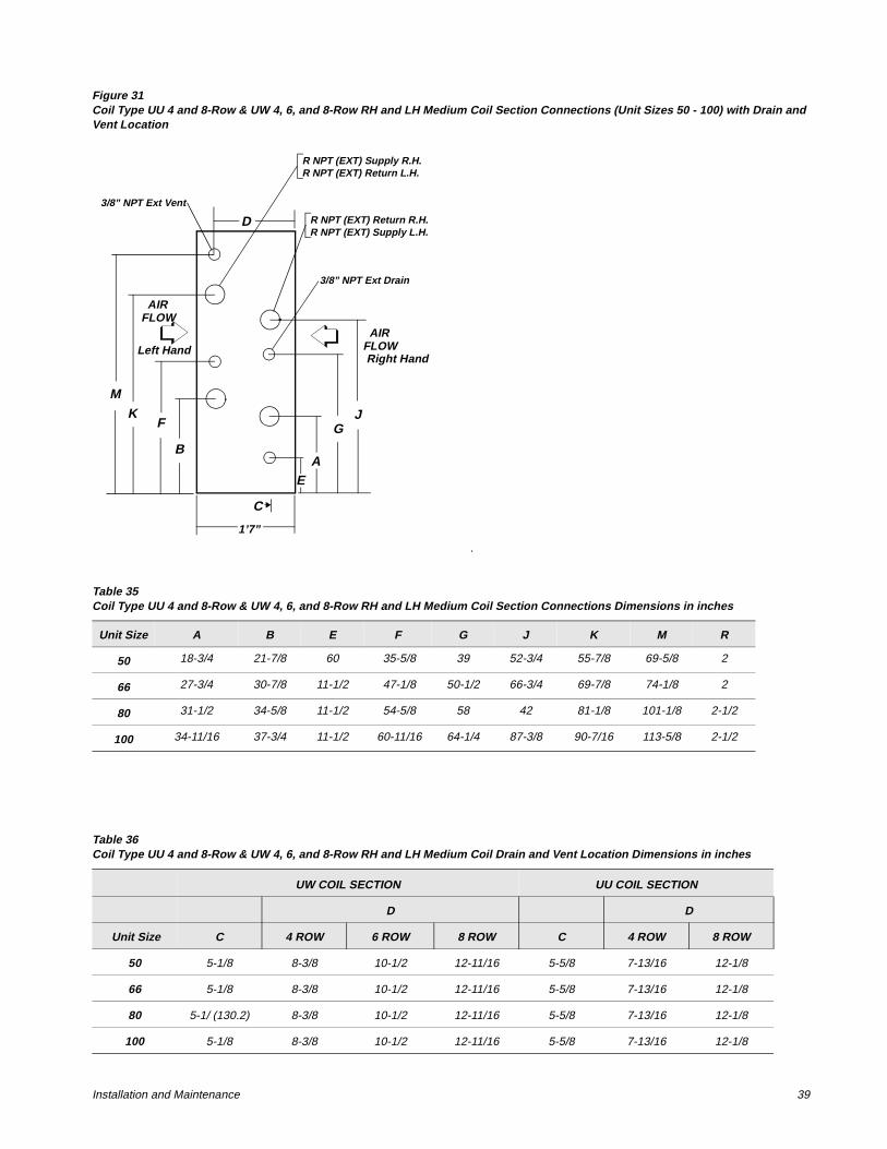
Figure 31Coil Type UU 4 and 8-Row & UW 4, 6, and 8-Row RH and LH Medium Coil Section Connections (Unit Sizes 50 - 100) with Drain and Vent Location
.
AIRFLOW
AIRFLOW
AB
C
D
E
F GJK
M
1’7”
R NPT (EXT) Supply R.H.R NPT (EXT) Return L.H.
R NPT (EXT) Return R.H.R NPT (EXT) Supply L.H.
3/8” NPT Ext Vent
3/8” NPT Ext Drain
Left HandRight Hand
Table 35Coil Type UU 4 and 8-Row & UW 4, 6, and 8-Row RH and LH Medium Coil Section Connections Dimensions in inches
Unit Size A B E F G J K M R
50 18-3/4 21-7/8 60 35-5/8 39 52-3/4 55-7/8 69-5/8 2
66 27-3/4 30-7/8 11-1/2 47-1/8 50-1/2 66-3/4 69-7/8 74-1/8 2
80 31-1/2 34-5/8 11-1/2 54-5/8 58 42 81-1/8 101-1/8 2-1/2
100 34-11/16 37-3/4 11-1/2 60-11/16 64-1/4 87-3/8 90-7/16 113-5/8 2-1/2
Table 36Coil Type UU 4 and 8-Row & UW 4, 6, and 8-Row RH and LH Medium Coil Drain and Vent Location Dimensions in inches
UW COIL SECTION UU COIL SECTION
D D
Unit Size C 4 ROW 6 ROW 8 ROW C 4 ROW 8 ROW
50 5-1/8 8-3/8 10-1/2 12-11/16 5-5/8 7-13/16 12-1/8
66 5-1/8 8-3/8 10-1/2 12-11/16 5-5/8 7-13/16 12-1/8
80 5-1/ (130.2) 8-3/8 10-1/2 12-11/16 5-5/8 7-13/16 12-1/8
100 5-1/8 8-3/8 10-1/2 12-11/16 5-5/8 7-13/16 12-1/8
40 CLCH-IM-16A
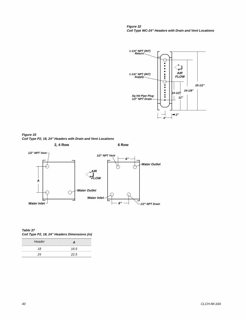
Figure 32Coil Type WC-24” Headers with Drain and Vent Locations
Figure 33Coil Type P2, 18, 24” Headers with Drain and Vent Locations
AIRFLOW
10-1/2”
12”
24-1/8”
25-1/2”
4”2”
1-1/4” NPT (INT)Return
1-1/4” NPT (INT)Supply
Sq Hd Pipe Plug1/2” NPT Drain
1/2” NPT Vent1/2” NPT Vent
1/2” NPT Drain
Water Inlet
Water Outlet
Water Outlet
Water Inlet
A
6”
6”
AIR
FLOW
2, 4 Row 6 Row
Table 37Coil Type P2, 18, 24” Headers Dimensions (in)
Header A
18 16.5
24 22.5
Installation and Maintenance 41
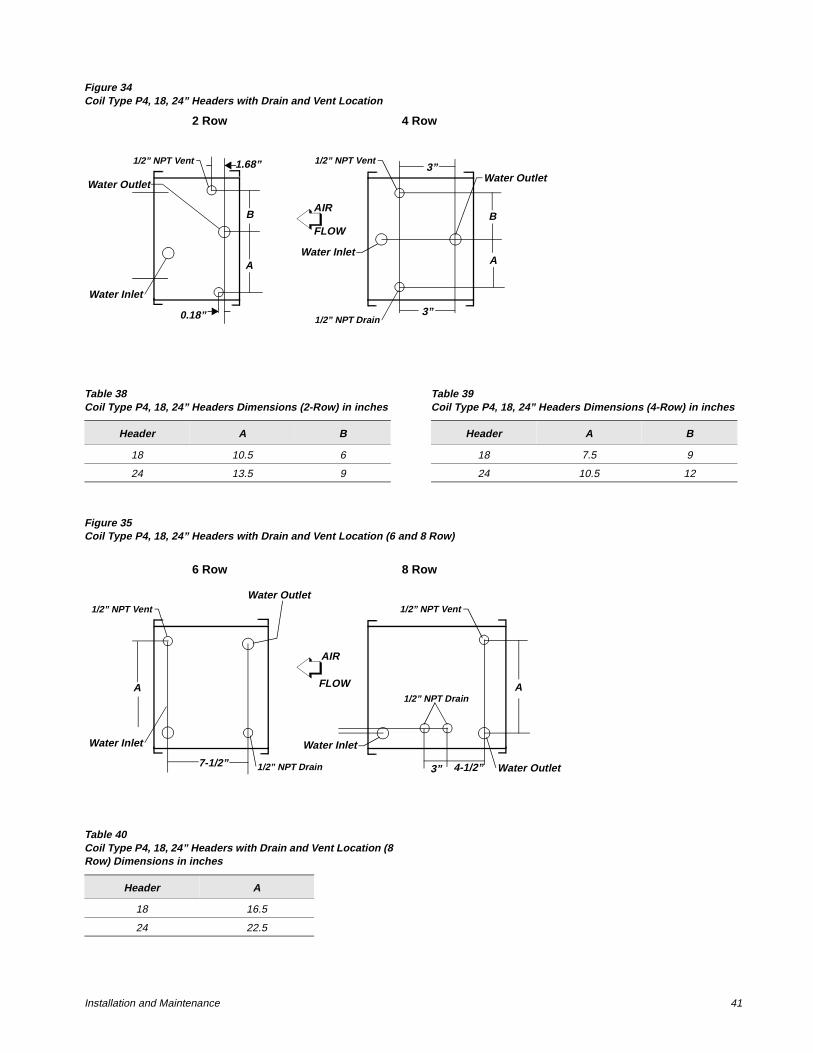
Figure 34Coil Type P4, 18, 24” Headers with Drain and Vent Location
Figure 35Coil Type P4, 18, 24” Headers with Drain and Vent Location (6 and 8 Row)
1/2” NPT Vent 1/2” NPT Vent
1/2” NPT Drain
Water Inlet
Water OutletWater Outlet
Water Inlet
3”
3”
AIR
FLOW
2 Row 4 Row
1.68”
0.18”
B
A
B
A
Table 38Coil Type P4, 18, 24” Headers Dimensions (2-Row) in inches
Header A B
18 10.5 6
24 13.5 9
Table 39Coil Type P4, 18, 24” Headers Dimensions (4-Row) in inches
Header A B
18 7.5 9
24 10.5 12
1/2” NPT Vent 1/2” NPT Vent
1/2” NPT Drain
Water Inlet
Water Outlet
Water Outlet
Water Inlet
3”
AIR
FLOW
6 Row 8 Row
A
7-1/2”
A
4-1/2”
1/2” NPT Drain
Table 40Coil Type P4, 18, 24” Headers with Drain and Vent Location (8 Row) Dimensions in inches
Header A
18 16.5
24 22.5
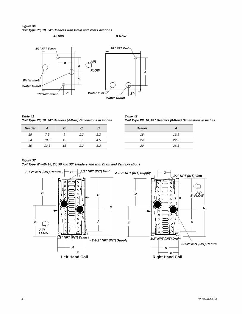
42 CLCH-IM-16A
Figure 36Coil Type P8, 18, 24” Headers with Drain and Vent Locations
Figure 37Coil Type W with 18, 24, 30 and 33” Headers and with Drain and Vent Locations
1/2” NPT Vent 1/2” NPT Vent
1/2” NPT Drain Water Inlet
Water Outlet
Water Outlet
Water Inlet
3”
AIR
FLOW
4 Row 8 Row
A
A
B
C
D
Table 41Coil Type P8, 18, 24” Headers (4-Row) Dimensions in inches
Header A B C D
18 7.5 9 1.2 1.2
24 10.5 12 0 4.5
30 13.5 15 1.2 1.2
Table 42Coil Type P8, 18, 24” Headers (8-Row) Dimensions in inches
Header A
18 16.5
24 22.5
30 28.5
G
A
B
C
D
E
F
H
G
A
B
C
D
E
F
H
2-1-2” NPT (INT) Return 1/2” NPT (INT) Vent
1/2” NPT (INT) Drain2-1-2” NPT (INT) Supply
2-1-2” NPT (INT) Return
1/2” NPT (INT) Vent
1/2” NPT (INT) Drain
2-1-2” NPT (INT) Supply
Left Hand Coil Right Hand Coil
AIRFLOW
AIRFLOW
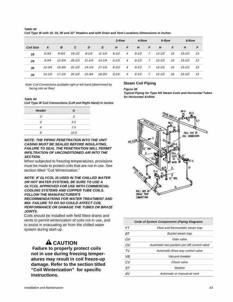
Installation and Maintenance 43
Note: Coil Connections available right or left hand (determined by facing into air flow)
NOTE: THE PIPING PENETRATION INTO THE UNIT CASING MUST BE SEALED BEFORE INSULATING. FAILURE TO SEAL THE PENETRATION WILL PERMIT INFILTRATION OF UNCONDITIONED AIR INTO THE SECTION.When subjected to freezing temperatures, provisions must be made to protect coils that are not in use. See section titled “Coil Winterization.”
NOTE: IF GLYCOL IS USED IN THE CHILLED WATER OR HOT WATER SYSTEMS, BE SURE TO USE A GLYCOL APPROVED FOR USE WITH COMMERCIAL COOLING SYSTEMS AND COPPER TUBE COILS. FOLLOW THE MANUFACTURER’S RECOMMENDATIONS FOR WATER TREATMENT AND MIX. FAILURE TO DO SO COULD AFFECT COIL PERFORMANCE OR DAMAGE THE TUBES OR BRAZE JOINTS. Coils should be installed with field fitted drains and vents to permit winterization of coils not in use, and to assist in evacuating air from the chilled water system during start-up.
CAUTION Failure to properly protect coils not in use during freezing temper-atures may result in coil freeze-up damage. Refer to the section titled “Coil Winterization” for specific instructions.
Steam Coil Piping
Figure 38Typical Piping for Type NS Steam Coils and Horizontal Tubes for Horizontal Airflow
Table 43Coil Type W with 18, 24, 30 and 33” Headers and with Drain and Vent Locations Dimensions in inches
2-Row 4-Row 6-Row 8-Row
Coil Size A B C D E H F H F H F H F
18 6-3/4 9-3/4 19-1/2 8-1/4 11-1/4 6-1/2 4 9-1/2 7 12-1/2 10 15-1/2 13
24 9-3/4 12-3/4 25-1/2 11-1/4 14-1/4 6-1/2 4 9-1/2 7 12-1/2 10 15-1/2 13
30 12-3/4 15-3/4 31-1/2 14-1/4 17-1/4 6-1/2 4 9-1/2 7 12-1/2 10 15-1/2 13
33 14-1/4 17-1/4 34-1/2 15-3/4 18-3/4 6-1/2 4 9-1/2 7 12-1/2 10 15-1/2 13
Table 44Coil Type W Coil Connections (Left and Right Hand) in inches
Header G
3 3
4 4.5
6 7.5
8 10.5
Code of System Components (Piping Diagrams
FT Float and thermostatic steam trap
BT Bucket steam trap
GV Gate valve
OV Automatic two-position (on-off) control valve
TV Automatic three-way control valve
VB Vacuum breaker
CV Check valve
ST Strainer
AV Automatic or manual air vent
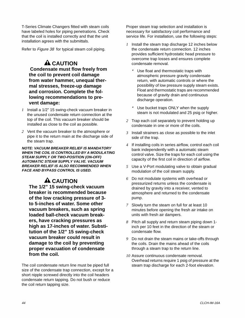
44 CLCH-IM-16A
T-Series Climate Changers fitted with steam coils have labeled holes for piping penetrations. Check that the coil is installed correctly and that the unit installation agrees with the submittals.
Refer to Figure 38 for typical steam coil piping.
CAUTION Condensate must flow freely from the coil to prevent coil damage from water hammer, unequal ther-mal stresses, freeze-up damage and corrosion. Complete the fol-lowing recommendations to pre-vent damage:
1 Install a 1/2” 15 swing-check vacuum breaker in the unused condensate return connection at the top of the coil. This vacuum breaker should be installed as close to the coil as possible.
2 Vent the vacuum breaker to the atmosphere or pipe it to the return main at the discharge side of the steam trap.
NOTE: VACUUM BREAKER RELIEF IS MANDATORY WHEN THE COIL IS CONTROLLED BY A MODULATING STEAM SUPPLY OR TWO-POSITION (ON-OFF) AUTOMATIC STEAM SUPPLY VALVE. VACUUM BREAKER RELIEF IS ALSO RECOMMENDED WHEN FACE AND BYPASS CONTROL IS USED.
CAUTIONThe 1/2” 15 swing-check vacuum breaker is recommended because of the low cracking pressure of 3- to 5-inches of water. Some other vacuum breakers, such as spring loaded ball-check vacuum break-ers, have cracking pressures as high as 17-inches of water. Substi-tution of the 1/2” 15 swing-check vacuum breaker could result in damage to the coil by preventing proper evacuation of condensate from the coil.
The coil condensate return line must be piped full size of the condensate trap connection, except for a short nipple screwed directly into the coil headers condensate return tapping. Do not bush or reduce the coil return tapping size.
Proper steam trap selection and installation is necessary for satisfactory coil performance and service life. For installation, use the following steps:
1 Install the steam trap discharge 12 inches below the condensate return connection. 12 inches provides sufficient hydrostatic head pressure to overcome trap losses and ensures complete condensate removal.
* Use float and thermostatic traps with atmospheric pressure gravity condensate return, with automatic controls or where the possibility of low pressure supply steam exists. Float and thermostatic traps are recommended because of gravity drain and continuous discharge operation.
* Use bucket traps ONLY when the supply steam is not modulated and 25 psig or higher.
2 Trap each coil separately to prevent holding up condensate in one or more of the coils.
3 Install strainers as close as possible to the inlet side of the trap.
4 If installing coils in series airflow, control each coil bank independently with a automatic steam control valve. Size the traps for each coil using the capacity of the first coil in direction of airflow.
5 Use a V-Port modulating valve to obtain gradual modulation of the coil steam supply.
6 Do not modulate systems with overhead or pressurized returns unless the condensate is drained by gravity into a receiver, vented to atmosphere and returned to the condensate pump.
7 Slowly turn the steam on full for at least 10 minutes before opening the fresh air intake on units with fresh air dampers.
8 Pitch all supply and return steam piping down 1-inch per 10 feet in the direction of the steam or condensate flow.
9 Do not drain the steam mains or take-offs through the coils. Drain the mains ahead of the coils through a steam trap to the return line.
10 Assure continuous condensate removal. Overhead returns require 1 psig of pressure at the steam trap discharge for each 2-foot elevation.
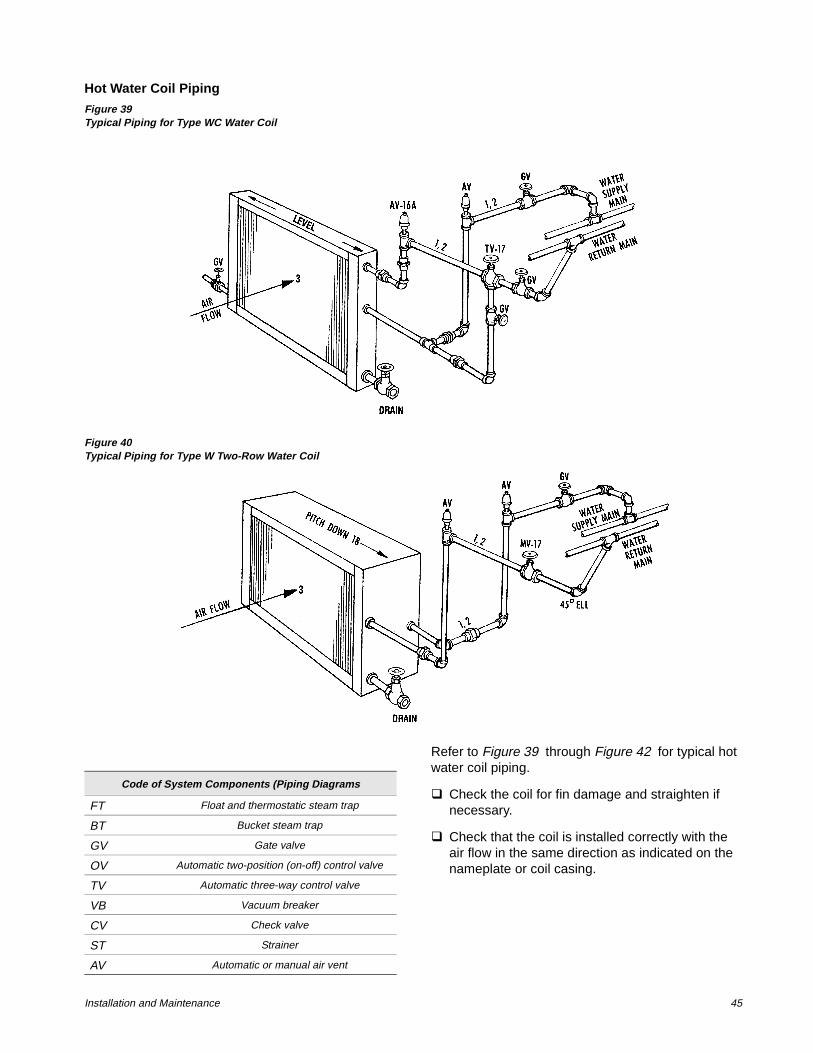
Installation and Maintenance 45
Hot Water Coil Piping
Figure 39Typical Piping for Type WC Water Coil
Figure 40Typical Piping for Type W Two-Row Water Coil
Refer to Figure 39 through Figure 42 for typical hot water coil piping.
q Check the coil for fin damage and straighten if necessary.
q Check that the coil is installed correctly with the air flow in the same direction as indicated on the nameplate or coil casing.
Code of System Components (Piping Diagrams
FT Float and thermostatic steam trap
BT Bucket steam trap
GV Gate valve
OV Automatic two-position (on-off) control valve
TV Automatic three-way control valve
VB Vacuum breaker
CV Check valve
ST Strainer
AV Automatic or manual air vent
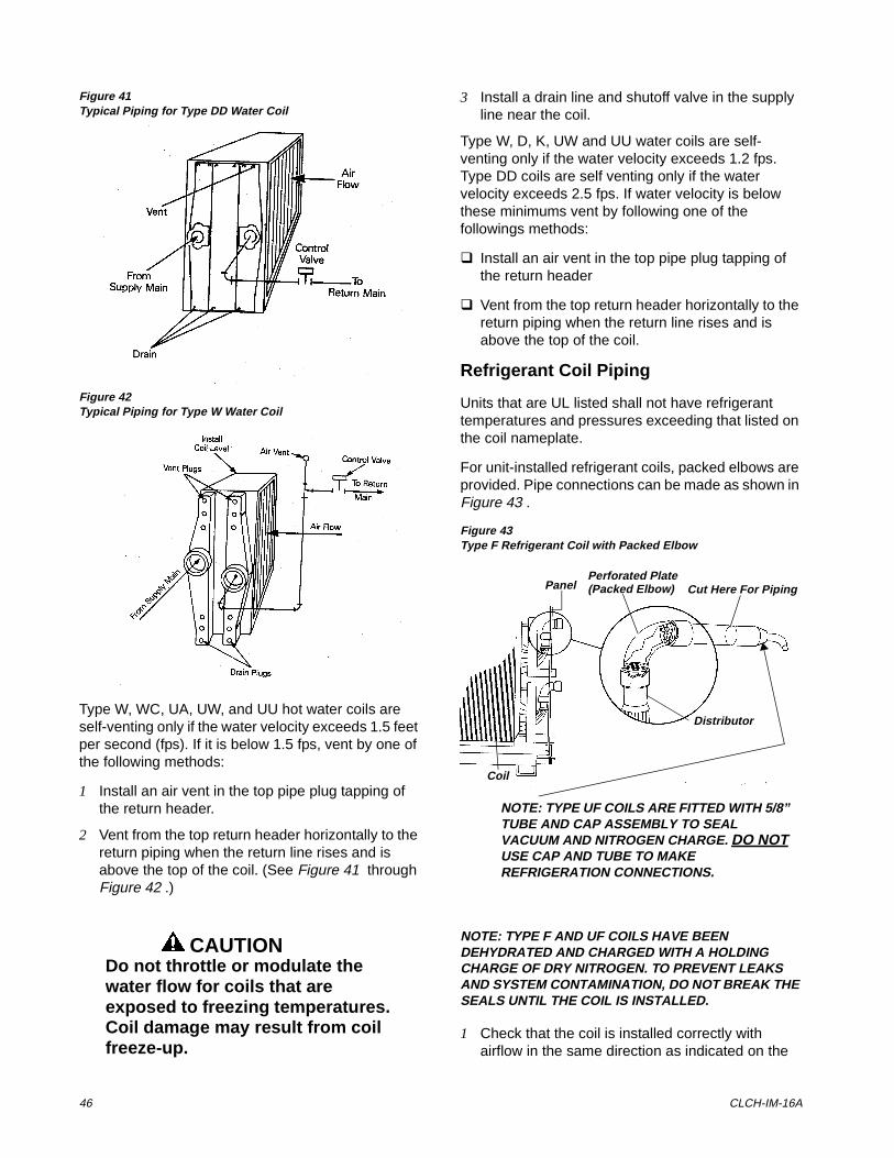
46 CLCH-IM-16A
Figure 41Typical Piping for Type DD Water Coil
Figure 42Typical Piping for Type W Water Coil
Type W, WC, UA, UW, and UU hot water coils are self-venting only if the water velocity exceeds 1.5 feet per second (fps). If it is below 1.5 fps, vent by one of the following methods:
1 Install an air vent in the top pipe plug tapping of the return header.
2 Vent from the top return header horizontally to the return piping when the return line rises and is above the top of the coil. (See Figure 41 through Figure 42 .)
CAUTIONDo not throttle or modulate the water flow for coils that are exposed to freezing temperatures. Coil damage may result from coil freeze-up.
3 Install a drain line and shutoff valve in the supply line near the coil.
Type W, D, K, UW and UU water coils are self-venting only if the water velocity exceeds 1.2 fps. Type DD coils are self venting only if the water velocity exceeds 2.5 fps. If water velocity is below these minimums vent by following one of the followings methods:
q Install an air vent in the top pipe plug tapping of the return header
q Vent from the top return header horizontally to the return piping when the return line rises and is above the top of the coil.
Refrigerant Coil Piping
Units that are UL listed shall not have refrigerant temperatures and pressures exceeding that listed on the coil nameplate.
For unit-installed refrigerant coils, packed elbows are provided. Pipe connections can be made as shown in Figure 43 .
Figure 43Type F Refrigerant Coil with Packed Elbow
NOTE: TYPE F AND UF COILS HAVE BEEN DEHYDRATED AND CHARGED WITH A HOLDING CHARGE OF DRY NITROGEN. TO PREVENT LEAKS AND SYSTEM CONTAMINATION, DO NOT BREAK THE SEALS UNTIL THE COIL IS INSTALLED.
1 Check that the coil is installed correctly with airflow in the same direction as indicated on the
Perforated Plate(Packed Elbow)Panel
Distributor
Coil
Cut Here For Piping
NOTE: TYPE UF COILS ARE FITTED WITH 5/8” TUBE AND CAP ASSEMBLY TO SEAL VACUUM AND NITROGEN CHARGE. DO NOT USE CAP AND TUBE TO MAKE REFRIGERATION CONNECTIONS.
Installation and Maintenance 47
coil nameplate or casing. The suction connection must be at the bottom of the suction header.
2 Follow accepted refrigeration piping practices and safely precautions for typical refrigerant coil piping and components. See Figure 43 . Specific recommendations are provided with the highside components, including instructions for pressure-testing, evacuation, and system charging. General recommendations for component selection and line sizing follow.
3 Leak-test the entire refrigeration system after all piping is complete.
4 Charge the unit according to approximate weight requirements, operating pressures and superheat/subcooling measurements.
5 Adjust the thermal expansion valve setting if necessary.
General Refrigerant Piping Recommendations
IMPORTANT: REFER TO THE NOTE ON THE INSIDE FRONT COVER OF THIS MANUAL REGARDING HANDLING OF REFRIGERANTS
Liquid Line Components
Trane recommends the use of a properly sized liquid line filter-drier installed upstream from the expansion valve and as close to the evaporator coil as possible. Base filter-drier selection on a maximum pressure drop of 2 psi at the design condition.
1 Install moisture indicator/sight glass between the expansion valve and filter-drier. The moisture indicator/sight glass must be sized to match the size of the liquid line at the thermal expansion valve.
2 Size liquid line shutoff valve with an access port using the selected liquid line OD, and install it close to the condenser.
3 Minimize use of other valves, tube bends and reducers since these items tend to increase pressure drop and to reduce subcooling at the expansion valve. Liquid line receivers, other than those factory-installed, are not recommended.
4 The Thermal Expansion Valve (TEV) must be selected for proper size and capacity. The size of the TEV should cover the full range of loadings. Check that the valve will successfully operate at the lightest load condition. Also consider the use of a hot gas bypass valve when sizing the TEV. Select expansion valves with external equalizer connections, and those designed to operate against a back pressure of 20 pounds per square inch higher than actual evaporator pressure.
5 Install the TEV directly on the coil liquid connection (distributor) provided. The liquid distributor must be in a true vertical position.
CAUTIONDisassemble the thermal expan-sion valve before completing the brazing connections. If necessary, wrap the valve in a cool, wet cloth while brazing. Failure to protect the valve from high temperatures may result in damage to the inter-nal components.
48 CLCH-IM-16A
Suction Line Components
Install suction line pressure tap on the leaving side of the evaporator coil near the TEV sensing bulb location. Accurate superheat measurement and thermal expansion valve adjustment demands that suction pressure be measured near the evaporator coil.
Usually, suction line filter-driers are only necessary on systems that have experienced a severe compressor motor burnout or other failure which results in extremely high refrigerant temperature. Do not leave this filter-drier in the suction line permanently.
Liquid Line Sizing
All compressors have a Refrigerant Charge Limit (RCL) that must not be exceeded. Since the RCL and pressure drop are in direct conflict with each other, Trane recommends that the liquid line be sized as small as possible, while maintaining a low enough pressure drop to ensure 5°F of subcooling at the expansion valve.
Suction Line Sizing
Suction line tubes must be sized to maintain refrigerant vapor velocities that are high enough to ensure oil entertainment under all operating conditions.
It is not necessary to pitch horizontal suction lines toward the compressor when the refrigerant coil is used with Trane condensing units that are designed with a gas trap in the suction line just prior to the compressor.
Installation and Maintenance 49
Wiring
WARNINGDisconnect electrical power source before servicing the unit or connecting electrical wires.
Failure to do so may result in per-sonal injury or death from electrical shock or entanglement in moving parts. If the unit includes a factory-mounted starter, use of the lockout/tagout on the disconnect is required while servicing the unit.
If the unit does not include a factory-mounted starter, wiring to the unit fan motor must be provided by the installer and must comply with all national and local electrical codes. The installer must also furnish a fused disconnect switch in compliance with national and local electrical codes. Fan motors require overload protective devices rated or selected in compliance with the National Electric Code or Canadian Electric Code. Specific unit and motor connection diagrams are attached to the unit.
CAUTIONUse copper conductors only for terminal connections. Use of alu-minum or other type of wiring may result in galvanic corrosion or overheating and resultant equip-ment damage.
Fan motors require motor overload protective devices that are rated or selected in compliance with the National Electric Code or Canadian Electric Code. Specific unit and motor connection diagrams are provided on the unit. If wiring directly to the motor, a flexible connection at the motor to permit fan belt adjustment should be provided. Fractional horsepower motors may be factory connected to a terminal box on the unit. If this construction is provided, the installer should complete field wiring to this connection box.
For a typical high voltage wiring schematic, see Figure 44 following.
Connection of junction sections to unit end devices is accomplished using the connections shown in Figure
23 . See unit control drawings for specific connection information.
For typical field wiring to units with DDC:
q Provide 120 VAC power for control. A dedicated circuit is recommended. Units with a factory-mounted starter or VFD do not require this circuit as they are powered by the oversized control transformer in the starter or VFD.
q If unit ships in multiple sections, fasten quick connects (Figure 23 ) before sections bolt together.
q Field mount and wire outside air sensor and space sensor, if ordered.
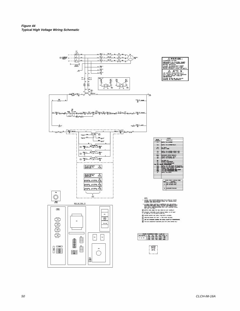
50 CLCH-IM-16A
Figure 44Typical High Voltage Wiring Schematic
Installation and Maintenance 51
,QVWDOODWLRQ�&KHFNOLVW
The following is an abbreviated list of the detailed installation information given in this manual and should be used as an aid to ensure proper installation. For complete instructions, refer to the appropriate sections of the manual.
WARNINGDisconnect electrical power source when servicing the unit. Failure to do so may result in injury or death from electrical shock. Secure drive sheaves before ser-vicing the unit to ensure that rotor cannot free-wheel. Failure to secure drive sheaves can cause severe personal injury.
1 Examine the unit and components for material shortage or shipping damage.
2 Check unit location for unit dimensions, weights and clearances.
3 Rig each section properly and hoist it to its final position.
4 For split ship units with factory mounted controls, connect color coded and numbered quick connect plugs (reference Figure 44 ).
5 Check that unit is installed level.
6 Remove fan isolator tie-down bolt, if unit is not externally isolated. See Figure 18 and Figure 19 .
7 Inspect Inlet Guide Vanes and adjust if necessary.
8 Install damper operator motors and connecting linkage. Check damper operation and linkage alignment.
9 Install filters, if supplied.
10 Connect supply and return air ductwork.
11 Complete coil and condensate drain piping connections.
12 Reference CLCH-IOP-1 for more details on the installation of units with factory mounted controls.
13 Complete electrical connections to the unit and PCM.
14 Leave the unit installation and maintenance manual with the unit.
Prestart-Up Checks
Before operating the unit, complete the following checks for safe and efficient operation.
WARNINGDisconnect electrical power source when connecting or dis-connecting electrical wires for test procedures. Do not open service access doors while the unit is operating. Failure to exercise cau-tion when completing test proce-dures or while inspecting unit operation may result in injury or death from electrical shock, air movement or rotating parts.
q Rotate all fan wheels manually. Fans should turn freely in the proper direction.
q Check fan drive belt tension.
NOTE: IF T-SERIES CLIMATE CHANGER FAN IS GOING TO OPERATE AT OTHER THAN DESIGN RPM OR WITH A VARIABLE SPEED DRIVE NOT SUPPLIED BY TRANE, THE UNIT VIBRATION LEVELS SHOULD BE CHECKED AT THE NEW RPM AND THROUGHOUT THE SPEED RANGE. RE-BALANCE OR CORRECT VIBRATIONS AS NECESSARY.
q Check fan hub set screws, sheave set screws and bearing set screws for proper torque (Table 45 ). Fan sheaves should be tight and aligned. Bearing set screws should be aligned. See section titled “Periodic Maintenance” for alignment instructions.
q Inspect fan motor and bearings for proper lubrication. Refer to Table 49 for fan grease recommendations. Contact the motor
Table 45Fan Bearing Setscrew Torque Settings (lb-ft)
Screw Size Hex Size Torque
1/4 1/8 5.5-7.5
5/16 5/32 10.5-13.7
3/8 3/16 19-25
7/16 7/32 29-37.5
1/2 1/4 42-54.2
52 CLCH-IM-16A
representative for motor lubrication recommendations.
q Inspect electrical connections. They should be clean and secure. Compare actual wiring with specific diagrams on the unit.
q Check piping and valve for leaks. Open or close the valves to check operation. Drain lines should be open.
q If unit has a refrigerant coil, it must be charged, leak-tested, and ready for operation according to instructions provided with the condenser equipment. Adjust superheat setting.
q Check that air filters are in place and positioned properly.
q Remove all foreign material from the drain pan and check pan opening and condensate line for obstructions.
q Check unit for debris.
q Close and secure all unit access doors.
Installation and Maintenance 53
6WDUW�8S
CAUTIONInadequate lubrication of fan motor or bearings may result in premature bearing or motor fail-ure.
1 Inspect electrical connections. They should be clean and secure. Compare actual wiring with specific diagrams provided on the unit.
2 Check piping and valves for leaks. Open or close the valves to check for proper operation. Drain lines should be open.
CAUTIONThe use of untreated or improperly treated water in unit coils may cause scaling, erosion, corrosion, algae, slime or other equipment damage. Consult a qualified water treatment specialist to determine if water treatment is required. The Trane Company assumes no responsibility for equipment dam-age caused by untreated or improperly treated water.
3 If equipped with a refrigerant coil, charge and leak-test the unit to and ready it for operation according to instructions provided with the condenser equipment. Adjust superheat setting.
4 Check that all air filters are in place and positioned properly. Under Periodic Maintenance, see section titled “Air Filters.”
NOTE: UL-LISTED UNITS REQUIRE A “TOOL-ONLY” REMOVABLE LATCH ON ACCESS DOORS. THE HANDLE TIE-DOWN SCREW SHIPPED WITH THE UNIT MEETS THIS REQUIREMENT, AND SHOULD REMAIN IN PLACE WHEN THE ACCESS DOOR IS CLOSED.
5 Close and secure all unit access doors. Check that the latch set screws are tight.
6 Remove all foreign material from the drain pan and check drain pan opening and condensate line for obstructions.
7 Check unit for debris.
8 Reference CLCH-IOP-1 for more details on the start-up of units with factory mounted controls.
Start-Up Procedures
After completing all prestart-up checks and procedures, the unit may be started. The following checks and adjustments should be made during initial start-up:
WARNINGDisconnect electrical power prior to access into a fan or ductwork. Even when locked out electrically, fans may cause injury or damage if the impeller is subject to “wind-milling.” The impeller should be secured to physically restrict rota-tional movement. Failure to secure impeller can cause severe per-sonal injury or death.
Disconnect electrical power source when connecting or dis-connecting electrical wires for test procedures. Do not open service access doors while the unit is operating. Failure to exercise cau-tion when completing test proce-dures or while inspecting unit operation may result in injury or death from electrical shock, air movement or rotating parts.
If the unit was stored for an extended period of time, the following items should be checked before starting the unit.
1 Inspect motor bearings for moisture and rust. Replace bearings if necessary and repack with new grease.
2 Check motor winding. An acceptable winding resistance reading is from 6 meg-ohms to infinity. If reading is less than 5 meg-ohms, winding should be dried out in an oven or by a blower.
3 Inspect the entire motor for rust and corrosion.
4 Lubricate the motor as instructed in the section titled “Periodic Maintenance,” or as indicated by the maintenance tag on the motor.
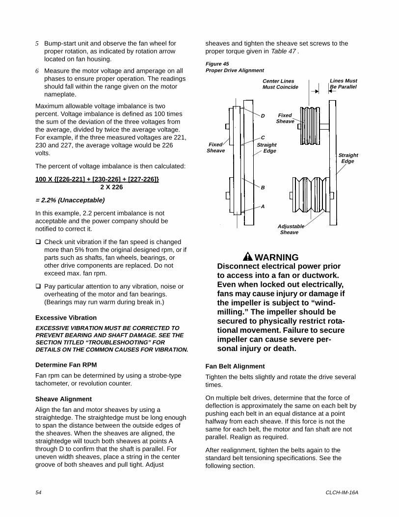
54 CLCH-IM-16A
5 Bump-start unit and observe the fan wheel for proper rotation, as indicated by rotation arrow located on fan housing.
6 Measure the motor voltage and amperage on all phases to ensure proper operation. The readings should fall within the range given on the motor nameplate.
Maximum allowable voltage imbalance is two percent. Voltage imbalance is defined as 100 times the sum of the deviation of the three voltages from the average, divided by twice the average voltage. For example, if the three measured voltages are 221, 230 and 227, the average voltage would be 226 volts.
The percent of voltage imbalance is then calculated:
100 X {[226-221] + [230-226] + [227-226]}2 X 226
= 2.2% (Unacceptable)
In this example, 2.2 percent imbalance is not acceptable and the power company should be notified to correct it.
q Check unit vibration if the fan speed is changed more than 5% from the original designed rpm, or if parts such as shafts, fan wheels, bearings, or other drive components are replaced. Do not exceed max. fan rpm.
q Pay particular attention to any vibration, noise or overheating of the motor and fan bearings. (Bearings may run warm during break in.)
Excessive Vibration
EXCESSIVE VIBRATION MUST BE CORRECTED TO PREVENT BEARING AND SHAFT DAMAGE. SEE THE SECTION TITLED “TROUBLESHOOTING” FOR DETAILS ON THE COMMON CAUSES FOR VIBRATION.
Determine Fan RPM
Fan rpm can be determined by using a strobe-type tachometer, or revolution counter.
Sheave Alignment
Align the fan and motor sheaves by using a straightedge. The straightedge must be long enough to span the distance between the outside edges of the sheaves. When the sheaves are aligned, the straightedge will touch both sheaves at points A through D to confirm that the shaft is parallel. For uneven width sheaves, place a string in the center groove of both sheaves and pull tight. Adjust
sheaves and tighten the sheave set screws to the proper torque given in Table 47 .
Figure 45Proper Drive Alignment
WARNINGDisconnect electrical power prior to access into a fan or ductwork. Even when locked out electrically, fans may cause injury or damage if the impeller is subject to “wind-milling.” The impeller should be secured to physically restrict rota-tional movement. Failure to secure impeller can cause severe per-sonal injury or death.
Fan Belt Alignment
Tighten the belts slightly and rotate the drive several times.
On multiple belt drives, determine that the force of deflection is approximately the same on each belt by pushing each belt in an equal distance at a point halfway from each sheave. If this force is not the same for each belt, the motor and fan shaft are not parallel. Realign as required.
After realignment, tighten the belts again to the standard belt tensioning specifications. See the following section.
Center LinesMust Coincide
Lines MustBe Parallel
FixedSheave
FixedSheave
StraightEdge
StraightEdge
AdjustableSheave
A
B
C
D
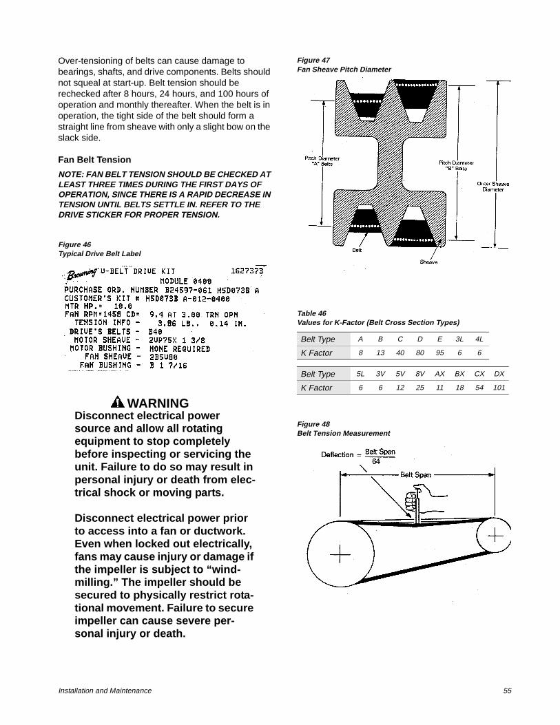
Installation and Maintenance 55
Over-tensioning of belts can cause damage to bearings, shafts, and drive components. Belts should not squeal at start-up. Belt tension should be rechecked after 8 hours, 24 hours, and 100 hours of operation and monthly thereafter. When the belt is in operation, the tight side of the belt should form a straight line from sheave with only a slight bow on the slack side.
Fan Belt Tension
NOTE: FAN BELT TENSION SHOULD BE CHECKED AT LEAST THREE TIMES DURING THE FIRST DAYS OF OPERATION, SINCE THERE IS A RAPID DECREASE IN TENSION UNTIL BELTS SETTLE IN. REFER TO THE DRIVE STICKER FOR PROPER TENSION.
Figure 46Typical Drive Belt Label
WARNINGDisconnect electrical power source and allow all rotating equipment to stop completely before inspecting or servicing the unit. Failure to do so may result in personal injury or death from elec-trical shock or moving parts.
Disconnect electrical power prior to access into a fan or ductwork. Even when locked out electrically, fans may cause injury or damage if the impeller is subject to “wind-milling.” The impeller should be secured to physically restrict rota-tional movement. Failure to secure impeller can cause severe per-sonal injury or death.
Figure 47Fan Sheave Pitch Diameter
Figure 48Belt Tension Measurement
Table 46Values for K-Factor (Belt Cross Section Types)
Belt Type A B C D E 3L 4L
K Factor 8 13 40 80 95 6 6
Belt Type 5L 3V 5V 8V AX BX CX DX
K Factor 6 6 12 25 11 18 54 101
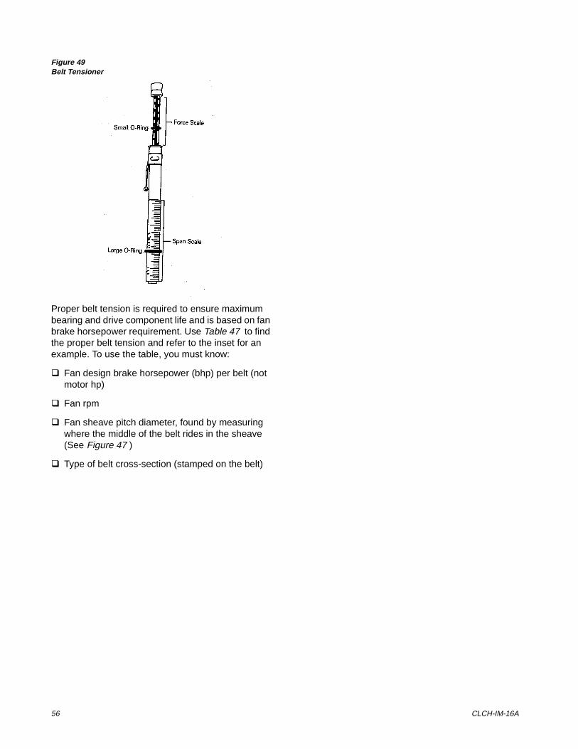
56 CLCH-IM-16A
Figure 49Belt Tensioner
Proper belt tension is required to ensure maximum bearing and drive component life and is based on fan brake horsepower requirement. Use Table 47 to find the proper belt tension and refer to the inset for an example. To use the table, you must know:
q Fan design brake horsepower (bhp) per belt (not motor hp)
q Fan rpm
q Fan sheave pitch diameter, found by measuring where the middle of the belt rides in the sheave (See Figure 47 )
q Type of belt cross-section (stamped on the belt)
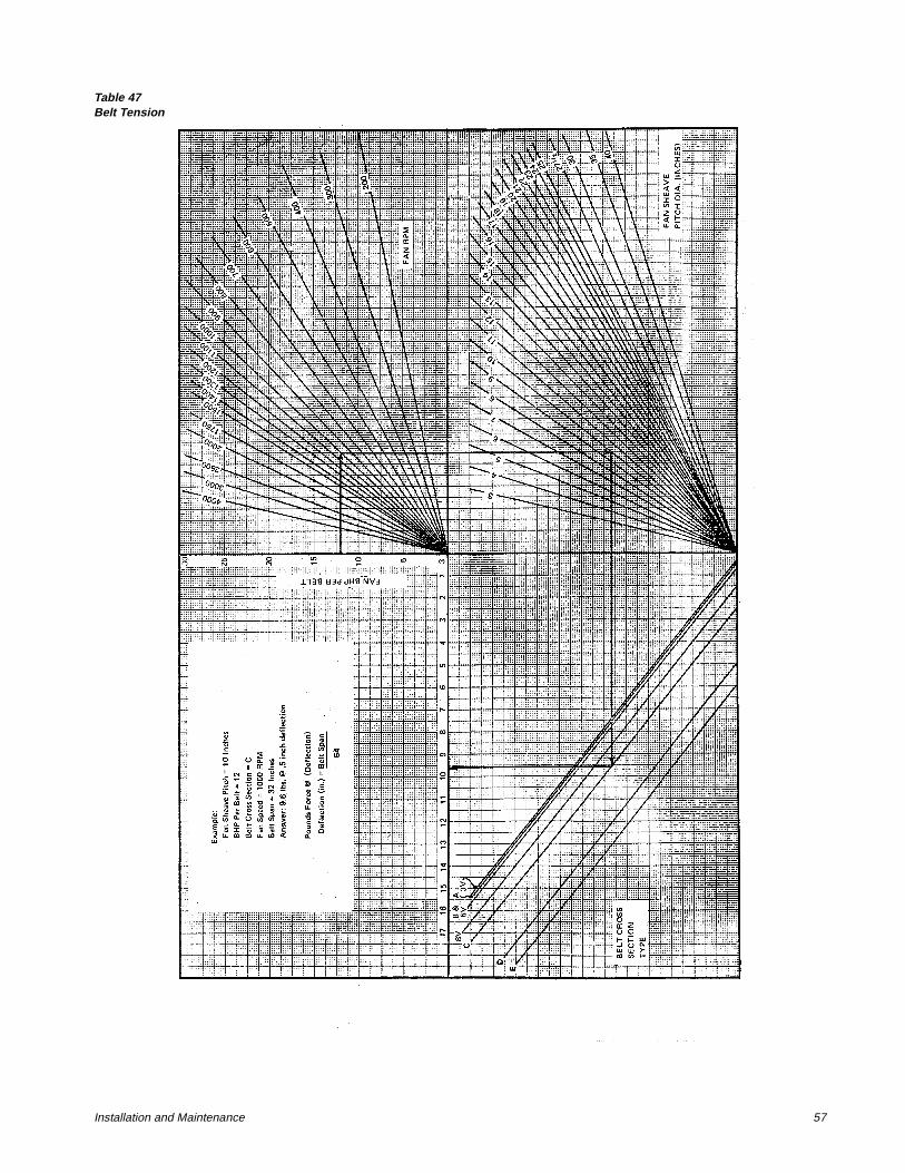
Installation and Maintenance 57
Table 47Belt Tension
58 CLCH-IM-16A
As shown in the example of Table 47 , the correct tension (pounds force) is 9.6 pounds, at 1/2-inch deflection. Deflection is determined by dividing the belt span distance by 64, as shown in Figure 48 .
To measure belt tension, use a belt tensiometer as shown in Figure 49 . Determine actual deflection by depressing one belt with the belt tensiometer and measuring the deflection relative to the other belts or to belt line. Adjust the belt tension to the correct pounds force and tighten all set screws to the proper torque. (See Table 47 .)
For belt cross-section types not given in Table 47 , use the following equations to calculate correct belt tension.
F = (T + K)/16
where
F = force measured in pounds at specific deflection.
K = constant determined by belt cross-section type.
T =24,750 (fan hp per belt)/ belt speed
Belt speed = ((fan pitch diameter)/12) X 3.1416 X fan rpm
For example, given the following:
Motor sheave pitch diameter: 5.7 inches, eight groove
Fan sheave pitch diameter: 10.0 inches, eight groove
Fan horsepower: 2.4 bhp
Fan rpm: 1000 rpm
Belt type: C
Sheave span: 32 inches
Belt speed = (10/12) X 3.14 X 1000 = 2618
T = (24,750 X (24 bhp/2 belts)/2618 = 113.4 lb
F = (13.4 + 40)/16 = 9.6 lb.
Also, D =(Belt span (inches))/64 = 32/64 =.50 in.
Therefore, the belt tensiometer should read 11.5 pounds force at 15/16-inch deflection. This will yield 159.4 pounds force belt tension.
Belt tensions determined by using Table 46 are minimum values. The correct operating tension for a V-belt drive is the lowest tension at which the belts will not slip under the peak load conditions. It may be necessary, however, to increase the tension of some drives to reduce excessive belt flopping or to reduce excessive start-up squealing.
NOTE: THERE IS A LABEL LOCATED ON THE BEARING SUPPORT ON THE DRIVE SIDE OF THE UNIT THAT LISTS ALL DRIVE PARTS AND THE PROPER BELT TENSION FOR THE SPECIFIC DRIVE.
CAUTIONDo not over-tension the belts. Excessive tension will reduce fan and motor bearing life, accelerate belt wear and possibly cause shaft failure.
Installation and Maintenance 59
3HULRGLF�0DLQWHQDQFH
The following checklist is provided as an abbreviated guide to periodic maintenance. Detailed procedural information is given after this checklist.
WARNINGDisconnect electrical power and allow rotating parts to stop before servicing the unit. Exercise cau-tion if unit must be on for test or maintenance procedures. Failure to do so may result in injury or death from electrical shock or moving parts.
Disconnect electrical power prior to access into a fan or ductwork. Even when locked out electrically, fans may cause injury or damage if the impeller is subject to “wind-milling.” The impeller should be secured to physically restrict rota-tional movement. Failure to secure impeller can cause severe per-sonal injury or death.
After 48 Hours Operation
Belts have acquired their permanent stretch. Readjust but do not over-tighten. See section titled “Fan Belt Tension” for instructions.
Weekly
Observe unit weekly for any change in running condition and unusual noise.
Every Month
q Check air filters. Clean or replace if clogged or dirty. Coat permanent filters with oil after cleaning. Change bag filters when pressure drop is 1-inch W.G.
q Relubricate fan bearings if operating conditions include high speeds, moist or dirty air, or high temperatures.
q Relubricate motor bearings in accordance with motor manufacturer’s recommendations if
operating conditions include high speeds, moist or dirty air, or high temperatures.
q Check and adjust fan belt tension.
Every Three to Six Months
q Check fan bearing grease line connections. Lines should be tight to the bearings.
q Relubricate fan bearings.
q Check motor lubrication. Recommendations are provided on the motor tag or on a unit sticker.
q Check bearing and motor bracket bolt torque.
q Align fan and motor sheaves. Tighten sheave set screws to the proper torque.
q Check and adjust fan belt tension.
q Tighten electrical connections.
q Inspect coils for dirt build-up or coil freeze-up.
Every Year
q Inspection the unit casing for corrosion. If damage is found, clean and repaint the surface with a rust-resistant primer and vinyl chlorinated lacquer.
q Clean the fan wheels and fan shaft. Remove rust with an emery cloth and apply a coat of LPS #3 or an equivalent.
q Inspect the condensate drain pan and drain line, remove sludge or foreign materials that might obstruct proper drainage. Remove obstacles.
Table 48Minimum Hex Head Bolt Torque in lb-ft
Grade 5 Bolts
Size (inches*)Thread
Designation Min. Torque
1/4, 20 UNC 6
1/4, 28 UNF 7
5/16, 18 UNC 14
5/16, 24 UNF 16
3/8, 16 UNC 24
3/8, 24 UNF 28
7/16, 14 UNC 42
7/16, 20 UNF 45
1/2, 13 UNC 69
1/2, 20 UNF 83
9/16, 12 UNC 99
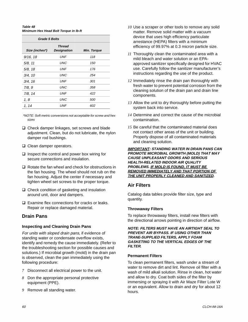
60 CLCH-IM-16A
*NOTE: Soft metric conversions not acceptable for screw and hex sizes
q Check damper linkages, set screws and blade adjustment. Clean, but do not lubricate, the nylon damper rod bushings.
q Clean damper operators.
q Inspect the control and power box wiring for secure connections and insulation.
q Rotate the fan wheel and check for obstructions in the fan housing. The wheel should not rub on the fan housing. Adjust the center if necessary and tighten wheel set screws to the proper torque.
q Check condition of gasketing and insulation around unit, door and dampers.
q Examine flex connections for cracks or leaks. Repair or replace damaged material.
Drain Pans
Inspecting and Cleaning Drain Pans
For units with sloped drain pans, if evidence of standing water or condensate overflow exists, identify and remedy the cause immediately. (Refer to the troubleshooting section for possible causes and solutions.) If microbial growth (mold) in the drain pan is observed, clean the pan immediately using the following procedure:
7 Disconnect all electrical power to the unit.
8 Don the appropriate personal protective equipment (PPE).
9 Remove all standing water.
10 Use a scraper or other tools to remove any solid matter. Remove solid matter with a vacuum device that uses high efficiency particulate arrestance (HEPA) filters with a minimum efficiency of 99.97% at 0.3 micron particle size.
11 Thoroughly clean the contaminated area with a mild bleach and water solution or an EPA-approved sanitizer specifically designed for HVAC use. Carefully follow the sanitizer manufacturer’s instructions regarding the use of the product.
12 Immediately rinse the drain pan thoroughly with fresh water to prevent potential corrosion from the cleaning solution of the drain pan and drain line components.
13 Allow the unit to dry thoroughly before putting the system back into service.
14 Determine and correct the cause of the microbial contamination.
15 Be careful that the contaminated material does not contact other areas of the unit or building. Properly dispose of all contaminated materials and cleaning solution.
IMPORTANT: STANDING WATER IN DRAIN PANS CAN PROMOTE MICROBIAL GROWTH (MOLD) THAT MAY CAUSE UNPLEASANT ODORS AND SERIOUS HEALTH-RELATED INDOOR AIR QUALITY PROBLEMS. IF MOLD IS FOUND, IT MUST BE REMOVED IMMEDIATELY AND THAT PORTION OF THE UNIT PROPERLY CLEANED AND SANITIZED.
Air Filters
Catalog data tables provide filter size, type and quantity.
Throwaway Filters
To replace throwaway filters, install new filters with the directional arrows pointing in direction of airflow.
NOTE: FILTERS MUST HAVE AN AIRTIGHT SEAL TO PREVENT AIR BYPASS. IF USING OTHER THAN TRANE-SUPPLIED FILTERS, APPLY FOAM GASKETING TO THE VERTICAL EDGES OF THE FILTER.
Permanent Filters
To clean permanent filters, wash under a stream of water to remove dirt and lint. Remove oil filter with a wash of mild alkali solution. Rinse in clean, hot water and allow to dry. Coat both sides of the filter by immersing or spraying it with Air Maze Filter Lote W or an equivalent. Allow to drain and dry for about 12 hours.
9/16, 18 UNF 118
5/8, 11 UNC 150
5/8, 18 UNF 176
3/4, 10 UNC 254
3/4, 16 UNF 301
7/8, 9 UNC 358
7/8, 14 UNF 422
1, 8 UNC 500
1, 14 UNF 602
Table 48Minimum Hex Head Bolt Torque in lb-ft
Grade 5 Bolts
Size (inches*)Thread
Designation Min. Torque
Installation and Maintenance 61
Cartridge or Bag Filters
To install cartridge or bag filters, complete the following:
WARNINGDisconnect electrical power source, and allow all rotating equipment to stop before inspect-ing or servicing the unit. Failure to do so may result in personal injury or death from electrical shock or rotating parts.
1 Open the filter section access door and remove the filters and block-offs from their installed position.
2 Keeping the bag filters folded, slide each filter into the filter rack, pushing them tightly against the unit. Pleats should be in the vertical position.
3 If using the optional pre-filters, slide them into the appropriate filter rack.
4 If fixed and adjustable block-offs are provided with the unit, slide the fixed block-offs into the filter track before the adjustable block-off. The adjustable block-off should always be installed last, next to the access door.
5 Close and secure the access door. If the door can be closed without compressing the filter, adjust the block-off by loosening its screws and position it to provide an airtight seal.
Fans
Inspecting and Cleaning Fans
Fan sections of air handlers should be inspected every six months at a minimum or more frequently if operating experience dictates. Accumulated dirt and organic matter on the interior surfaces of fans should be cleaned immediately. The suggested procedure for cleaning these surfaces is:
1 Disconnect all electrical power to the unit.
2 Don the appropriate personal protective equipment (PPE).
3 Use a portable vacuum with HEPA filtration to remove the loose dirt and organic matter. The filter should be 99.97% efficient at 0.3 micron particle size.
4 If no microbial growth (mold) exists, thoroughly clean the fan and associated components with an
industrial cleaning solution. Carefully follow the cleaning solution manufacturers instructions regarding use of their product.
5 If microbial growth (mold) is present, remove the contamination (Step 2) and thoroughly clean the affected area with an EPA-approved sanitizer specifically designed for HVAC use. Carefully follow the sanitizer manufacturers instructions regarding the use of the product.
6 Rinse the affected surfaces thoroughly with fresh water and a fresh sponge to prevent potential corrosion of metal surfaces.
7 Allow the unit to dry completely before putting it back into service.
8 Use caution to assure that any contaminated material does not contact other areas of the unit or building. Properly dispose of all contaminated materials and cleaning solution.
IMPORTANT: IF MICROBIAL GROWTH (MOLD) WAS FOUND, THE CAUSE OF THE CONTAMINATION MUST BE DETERMINED AND ACTION TAKEN TO ASSURE IT DOES NOT RECUR.
Fan Bearings and Motors
Bearing Set screw Alignment
Align bearing set screws as illustrated in Figure 50 . Reference Table 45 for bearing set screw torque.
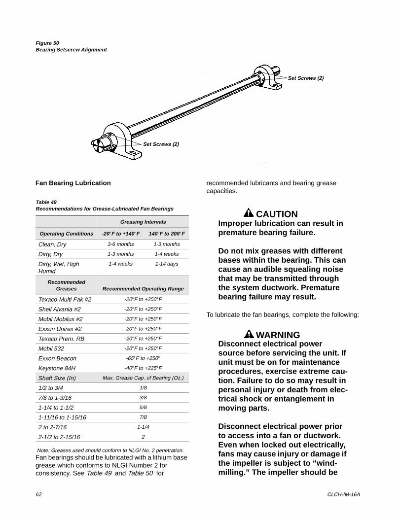
62 CLCH-IM-16A
Figure 50Bearing Setscrew Alignment
Fan Bearing Lubrication
Note: Greases used should conform to NLGI No. 2 penetration.Fan bearings should be lubricated with a lithium base grease which conforms to NLGI Number 2 for consistency. See Table 49 and Table 50 for
recommended lubricants and bearing grease capacities.
CAUTIONImproper lubrication can result in premature bearing failure.
Do not mix greases with different bases within the bearing. This can cause an audible squealing noise that may be transmitted through the system ductwork. Premature bearing failure may result.
To lubricate the fan bearings, complete the following:
WARNINGDisconnect electrical power source before servicing the unit. If unit must be on for maintenance procedures, exercise extreme cau-tion. Failure to do so may result in personal injury or death from elec-trical shock or entanglement in moving parts.
Disconnect electrical power prior to access into a fan or ductwork. Even when locked out electrically, fans may cause injury or damage if the impeller is subject to “wind-milling.” The impeller should be
Set Screws (2)
Set Screws (2)
Table 49Recommendations for Grease-Lubricated Fan Bearings
Greasing Intervals
Operating Conditions -20°F to +140°F 140°F to 200°F
Clean, Dry 3-6 months 1-3 months
Dirty, Dry 1-3 months 1-4 weeks
Dirty, Wet, High Humid.
1-4 weeks 1-14 days
Recommended Greases Recommended Operating Range
Texaco-Multi Fak #2 -20°F to +250°F
Shell Alvania #2 -20°F to +250°F
Mobil Mobilux #2 -20°F to +250°F
Exxon Unirex #2 -20°F to +250°F
Texaco Prem. RB -20°F to +250°F
Mobil 532 -20°F to +250°F
Exxon Beacon -65°F to +250°
Keystone 84H -40°F to +225°F
Shaft Size (In) Max. Grease Cap. of Bearing (Oz.)
1/2 to 3/4 1/8
7/8 to 1-3/16 3/8
1-1/4 to 1-1/2 5/8
1-11/16 to 1-15/16 7/8
2 to 2-7/16 1-1/4
2-1/2 to 2-15/16 2
Installation and Maintenance 63
secured to physically restrict rota-tional movement. Failure to secure impeller can cause severe per-sonal injury or death.
1 Disconnect main power switch.
2 Check grease lines for tight connections at the grease fitting.
3 Using a manual low pressure grease gun, add grease until a light bead of grease appears at the bearing grease seal. Turn the fan wheel manually while adding grease.
Fan Motors
Inspect fan motors periodically for excessive vibration or temperature. Operating conditions will vary the frequency of inspection and lubrication. Table 51 lists recommended motor greasing intervals. Motor lubrication instructions are found on the motor tag or nameplate. For a list of compatible greases, see Table 49 .
To relubricate the motor, consult the maintenance tag provided by the vendor.
Refer to Table 48 for minimum torque of motor mounting and bearings bolts.
WARNINGDisconnect power source for motor lubrication. Failure to do so may result in injury or death.
Disconnect electrical power prior to access into a fan or ductwork. Even when locked out electrically, fans may cause injury or damage if the impeller is subject to “wind-milling.” The impeller should be secured to physically restrict rota-tional movement. Failure to secure impeller can cause severe per-sonal injury or death.
Coil Cleaning
The frequency of required cleaning is dependent on the operating hours of the system, filter maintenance and efficiency and dirt load.
IMPORTANT: COILS BECOME EXTERNALLY FOULED AS A RESULT OF NORMAL OPERATION. DIRT ON THE SURFACE OF THE COIL REDUCES IT’S ABILITY TO TRANSFER HEAT THAT CAN RESULT IN COMFORT PROBLEMS, INCREASED RESISTANCE TO AIR FLOW AND THUS INCREASED OPERATING ENERGY COSTS. IF THE DIRT ON THE SURFACE OF THE COIL BECOMES WET, SUCH AS COMMONLY OCCURS WITH COOLING COILS, MICROBIAL GROWTH (MOLD) CAN RESULT THAT MAY CAUSE UNPLEASANT ODORS AND SERIOUS HEALTH-RELATED INDOOR AIR QUALITY PROBLEMS.
Steam, hot water and chilled water coils
Steam, hot water and chilled water coils should be kept clean to maintain maximum performance. If fins become dirty, clean with steam and detergent, hot water spray and detergent, or one of the commercially available chemical coil cleaners. Rinse coils thoroughly after cleaning.
WARNINGFollow all directions provided with chemical cleaners to avoid per-sonal injury and/or coil damage. Commercially available chemical cleaners may contain caustic or hazardous agents.
Table 50Fan Bearing Maximum Grease Capacity
Shaft Size in inches Capacity in fl. oz.
1/2 - 3/4 1/7
7/8 - 1-3/16 3/8
1-1/4 - 1-1/2 5/8
1-11/16 - 1-15/16 7/8
2 - 2-7/16 1-1/4
2-1/2 - 2-15/16 2
Table 51Recommended Motor Greasing Schedule
Avg. Daily Operating
HoursAvg.
Environment.3 to 7.5 HP
Motors10 to 30 HP
Motors
8-16 Clean and Dry
Every 5 years Every 3 years
12-24 Moderate Dirt or Moisture
Every 2 years Every year
Any Severe (very dirty or high
temperatures)
Every 6 months
Every 3 months
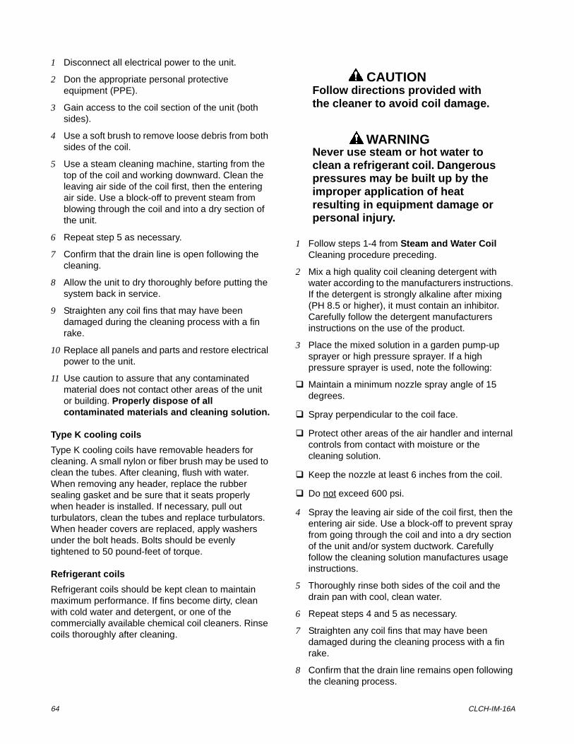
64 CLCH-IM-16A
1 Disconnect all electrical power to the unit.
2 Don the appropriate personal protective equipment (PPE).
3 Gain access to the coil section of the unit (both sides).
4 Use a soft brush to remove loose debris from both sides of the coil.
5 Use a steam cleaning machine, starting from the top of the coil and working downward. Clean the leaving air side of the coil first, then the entering air side. Use a block-off to prevent steam from blowing through the coil and into a dry section of the unit.
6 Repeat step 5 as necessary.
7 Confirm that the drain line is open following the cleaning.
8 Allow the unit to dry thoroughly before putting the system back in service.
9 Straighten any coil fins that may have been damaged during the cleaning process with a fin rake.
10 Replace all panels and parts and restore electrical power to the unit.
11 Use caution to assure that any contaminated material does not contact other areas of the unit or building. Properly dispose of all contaminated materials and cleaning solution.
Type K cooling coils
Type K cooling coils have removable headers for cleaning. A small nylon or fiber brush may be used to clean the tubes. After cleaning, flush with water. When removing any header, replace the rubber sealing gasket and be sure that it seats properly when header is installed. If necessary, pull out turbulators, clean the tubes and replace turbulators. When header covers are replaced, apply washers under the bolt heads. Bolts should be evenly tightened to 50 pound-feet of torque.
Refrigerant coils
Refrigerant coils should be kept clean to maintain maximum performance. If fins become dirty, clean with cold water and detergent, or one of the commercially available chemical coil cleaners. Rinse coils thoroughly after cleaning.
CAUTIONFollow directions provided with the cleaner to avoid coil damage.
WARNINGNever use steam or hot water to clean a refrigerant coil. Dangerous pressures may be built up by the improper application of heat resulting in equipment damage or personal injury.
1 Follow steps 1-4 from Steam and Water Coil Cleaning procedure preceding.
2 Mix a high quality coil cleaning detergent with water according to the manufacturers instructions. If the detergent is strongly alkaline after mixing (PH 8.5 or higher), it must contain an inhibitor. Carefully follow the detergent manufacturers instructions on the use of the product.
3 Place the mixed solution in a garden pump-up sprayer or high pressure sprayer. If a high pressure sprayer is used, note the following:
q Maintain a minimum nozzle spray angle of 15 degrees.
q Spray perpendicular to the coil face.
q Protect other areas of the air handler and internal controls from contact with moisture or the cleaning solution.
q Keep the nozzle at least 6 inches from the coil.
q Do not exceed 600 psi.
4 Spray the leaving air side of the coil first, then the entering air side. Use a block-off to prevent spray from going through the coil and into a dry section of the unit and/or system ductwork. Carefully follow the cleaning solution manufactures usage instructions.
5 Thoroughly rinse both sides of the coil and the drain pan with cool, clean water.
6 Repeat steps 4 and 5 as necessary.
7 Straighten any coil fins that may have been damaged during the cleaning process with a fin rake.
8 Confirm that the drain line remains open following the cleaning process.
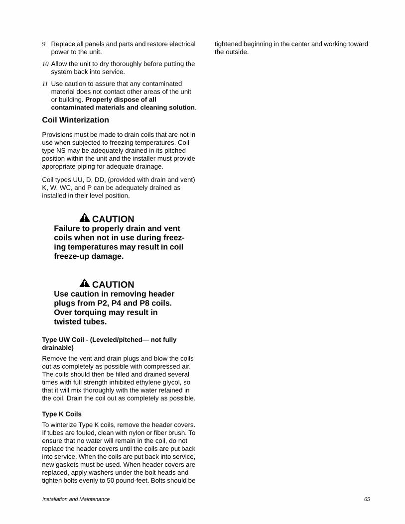
Installation and Maintenance 65
9 Replace all panels and parts and restore electrical power to the unit.
10 Allow the unit to dry thoroughly before putting the system back into service.
11 Use caution to assure that any contaminated material does not contact other areas of the unit or building. Properly dispose of all contaminated materials and cleaning solution.
Coil Winterization
Provisions must be made to drain coils that are not in use when subjected to freezing temperatures. Coil type NS may be adequately drained in its pitched position within the unit and the installer must provide appropriate piping for adequate drainage.
Coil types UU, D, DD, (provided with drain and vent) K, W, WC, and P can be adequately drained as installed in their level position.
CAUTIONFailure to properly drain and vent coils when not in use during freez-ing temperatures may result in coil freeze-up damage.
CAUTIONUse caution in removing header plugs from P2, P4 and P8 coils. Over torquing may result in twisted tubes.
Type UW Coil - (Leveled/pitched— not fully drainable)
Remove the vent and drain plugs and blow the coils out as completely as possible with compressed air. The coils should then be filled and drained several times with full strength inhibited ethylene glycol, so that it will mix thoroughly with the water retained in the coil. Drain the coil out as completely as possible.
Type K Coils
To winterize Type K coils, remove the header covers. If tubes are fouled, clean with nylon or fiber brush. To ensure that no water will remain in the coil, do not replace the header covers until the coils are put back into service. When the coils are put back into service, new gaskets must be used. When header covers are replaced, apply washers under the bolt heads and tighten bolts evenly to 50 pound-feet. Bolts should be
tightened beginning in the center and working toward the outside.
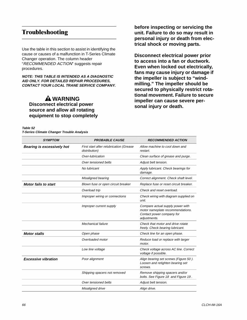
66 CLCH-IM-16A
7URXEOHVKRRWLQJ
Use the table in this section to assist in identifying the cause or causes of a malfunction in T-Series Climate Changer operation. The column header “RECOMMENDED ACTION” suggests repair procedures.
NOTE: THIS TABLE IS INTENDED AS A DIAGNOSTIC AID ONLY. FOR DETAILED REPAIR PROCEDURES, CONTACT YOUR LOCAL TRANE SERVICE COMPANY.
WARNINGDisconnect electrical power source and allow all rotating equipment to stop completely
before inspecting or servicing the unit. Failure to do so may result in personal injury or death from elec-trical shock or moving parts.
Disconnect electrical power prior to access into a fan or ductwork. Even when locked out electrically, fans may cause injury or damage if the impeller is subject to “wind-milling.” The impeller should be secured to physically restrict rota-tional movement. Failure to secure impeller can cause severe per-sonal injury or death.
Table 52T-Series Climate Changer Trouble Analysis
SYMPTOM PROBABLE CAUSE RECOMMENDED ACTION
Bearing is excessively hot First start after relubrication (Grease distribution)
Allow machine to cool down and restart.
Over-lubrication Clean surface of grease and purge.
Over tensioned belts Adjust belt tension.
No lubricant Apply lubricant. Check bearings for damage.
Misaligned bearing Correct alignment. Check shaft level.
Motor fails to start Blown fuse or open circuit breaker Replace fuse or reset circuit breaker.
Overload trip Check and reset overload.
Improper wiring or connections Check wiring with diagram supplied on unit.
Improper current supply Compare actual supply power with motor nameplate recommendations. Contact power company for adjustments.
Mechanical failure Check that motor and drive rotate freely. Check bearing lubricant.
Motor stalls Open phase Check line for an open phase.
Overloaded motor Reduce load or replace with larger motor.
Low line voltage Check voltage across AC line. Correct voltage if possible.
Excessive vibration Poor alignment Align bearing set screws (Figure 50 ). Loosen and retighten bearing set screws.
Shipping spacers not removed Remove shipping spacers and/or bolts. See Figure 18 and Figure 19 .
Over tensioned belts Adjust belt tension.
Misaligned drive Align drive.
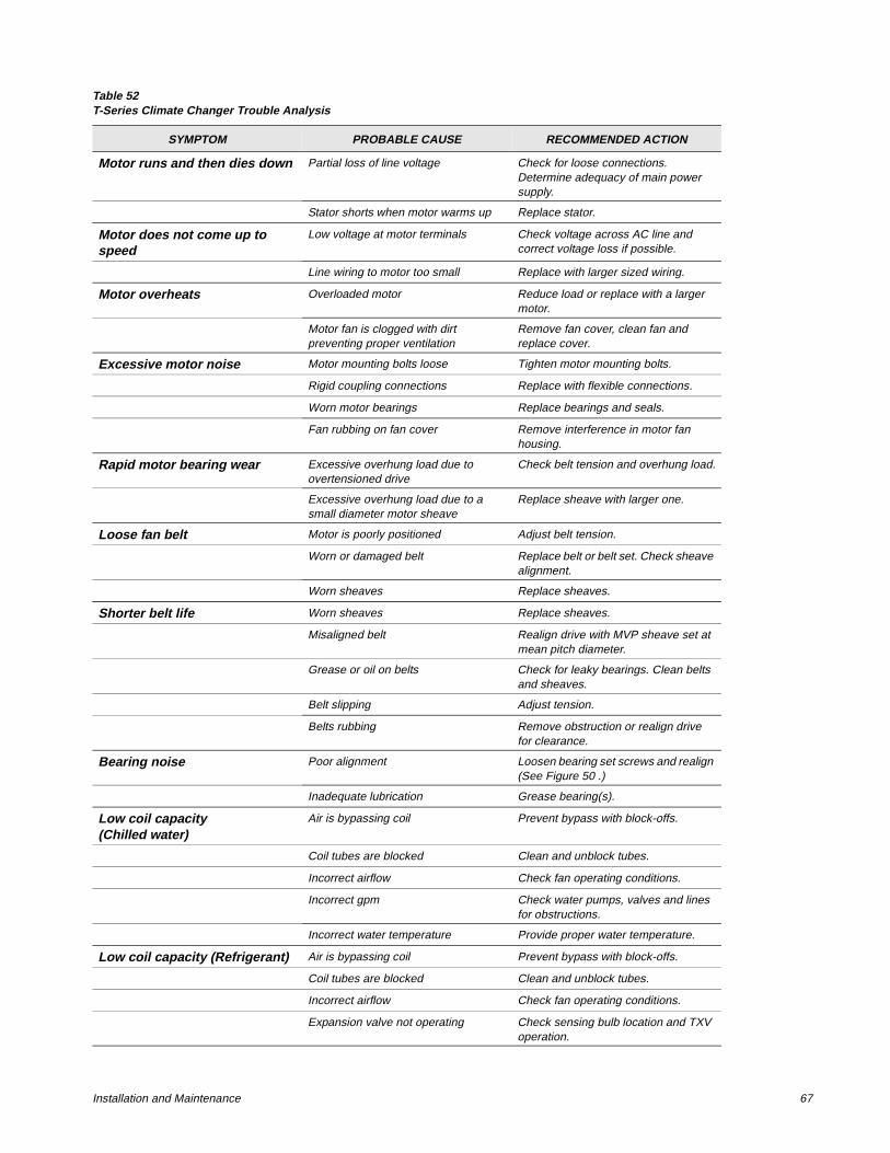
Installation and Maintenance 67
Motor runs and then dies down Partial loss of line voltage Check for loose connections. Determine adequacy of main power supply.
Stator shorts when motor warms up Replace stator.
Motor does not come up to speed
Low voltage at motor terminals Check voltage across AC line and correct voltage loss if possible.
Line wiring to motor too small Replace with larger sized wiring.
Motor overheats Overloaded motor Reduce load or replace with a larger motor.
Motor fan is clogged with dirt preventing proper ventilation
Remove fan cover, clean fan and replace cover.
Excessive motor noise Motor mounting bolts loose Tighten motor mounting bolts.
Rigid coupling connections Replace with flexible connections.
Worn motor bearings Replace bearings and seals.
Fan rubbing on fan cover Remove interference in motor fan housing.
Rapid motor bearing wear Excessive overhung load due to overtensioned drive
Check belt tension and overhung load.
Excessive overhung load due to a small diameter motor sheave
Replace sheave with larger one.
Loose fan belt Motor is poorly positioned Adjust belt tension.
Worn or damaged belt Replace belt or belt set. Check sheave alignment.
Worn sheaves Replace sheaves.
Shorter belt life Worn sheaves Replace sheaves.
Misaligned belt Realign drive with MVP sheave set at mean pitch diameter.
Grease or oil on belts Check for leaky bearings. Clean belts and sheaves.
Belt slipping Adjust tension.
Belts rubbing Remove obstruction or realign drive for clearance.
Bearing noise Poor alignment Loosen bearing set screws and realign (See Figure 50 .)
Inadequate lubrication Grease bearing(s).
Low coil capacity(Chilled water)
Air is bypassing coil Prevent bypass with block-offs.
Coil tubes are blocked Clean and unblock tubes.
Incorrect airflow Check fan operating conditions.
Incorrect gpm Check water pumps, valves and lines for obstructions.
Incorrect water temperature Provide proper water temperature.
Low coil capacity (Refrigerant) Air is bypassing coil Prevent bypass with block-offs.
Coil tubes are blocked Clean and unblock tubes.
Incorrect airflow Check fan operating conditions.
Expansion valve not operating Check sensing bulb location and TXV operation.
Table 52T-Series Climate Changer Trouble Analysis
SYMPTOM PROBABLE CAUSE RECOMMENDED ACTION
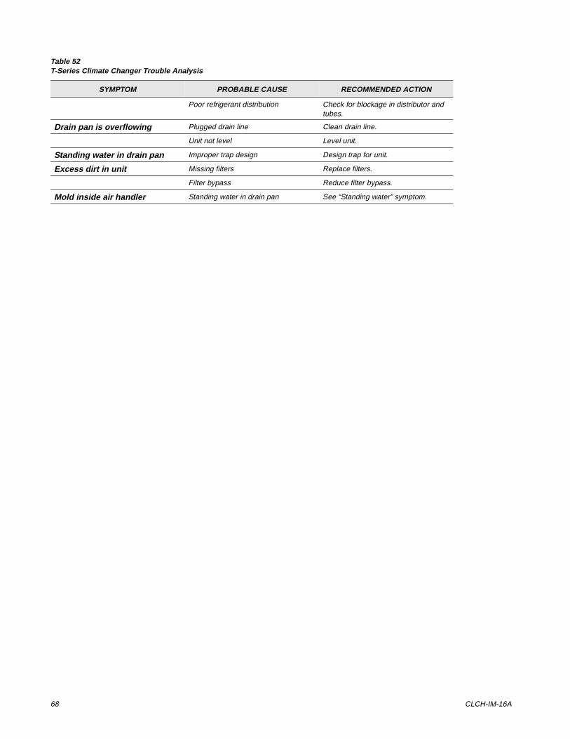
68 CLCH-IM-16A
Poor refrigerant distribution Check for blockage in distributor and tubes.
Drain pan is overflowing Plugged drain line Clean drain line.
Unit not level Level unit.
Standing water in drain pan Improper trap design Design trap for unit.
Excess dirt in unit Missing filters Replace filters.
Filter bypass Reduce filter bypass.
Mold inside air handler Standing water in drain pan See “Standing water” symptom.
Table 52T-Series Climate Changer Trouble Analysis
SYMPTOM PROBABLE CAUSE RECOMMENDED ACTION