T-P22 Low Voltage Cable Fault Locator - kehui.co.uk handout.pdf · T-P22 Low Voltage Cable Fault...
11
T-P22 Low Voltage Cable Fault Locator Remotely controllable TDR & Disturbance Recorder designed specifically for low voltage power cable fault location Locates permanent, intermittent & transitory faults Safe connection to energised cables via heavy duty fused test leads Internal GSM modem allows control and interrogation from anywhere in the world Stores last 20 events with 64 TDR traces (30 ‘pre-fault’ and 34 ‘post-fault’) PLUS 10 cycles of AC voltage/current waveforms Triggered from voltage distortion and/or over-current Used in conjunction with T-V22 LV Cable Fault Monitor to provide 3 phase voltage gradient fault location system 2, or more, T-P22 units can be configured to operate as a quasi- synchronous Travelling Wave Fault Location System
Transcript of T-P22 Low Voltage Cable Fault Locator - kehui.co.uk handout.pdf · T-P22 Low Voltage Cable Fault...
T-P22 Low Voltage Cable Fault Locator
Remotely controllable TDR & Disturbance Recorder designed specifically for low voltage power cable fault location
Locates permanent, intermittent & transitory faults
Safe connection to energised cables via heavy duty fused test leads
Internal GSM modem allows control and interrogation from anywhere in the world
Stores last 20 events with 64 TDR traces (30 ‘pre-fault’ and 34 ‘post-fault’) PLUS 10 cycles of AC voltage/current waveforms
Triggered from voltage distortion and/or over-current
Used in conjunction with T-V22 LV Cable Fault Monitor to provide 3 phase voltage gradient fault location system
2, or more, T-P22 units can be configured to operate as a quasi-synchronous Travelling Wave Fault Location System
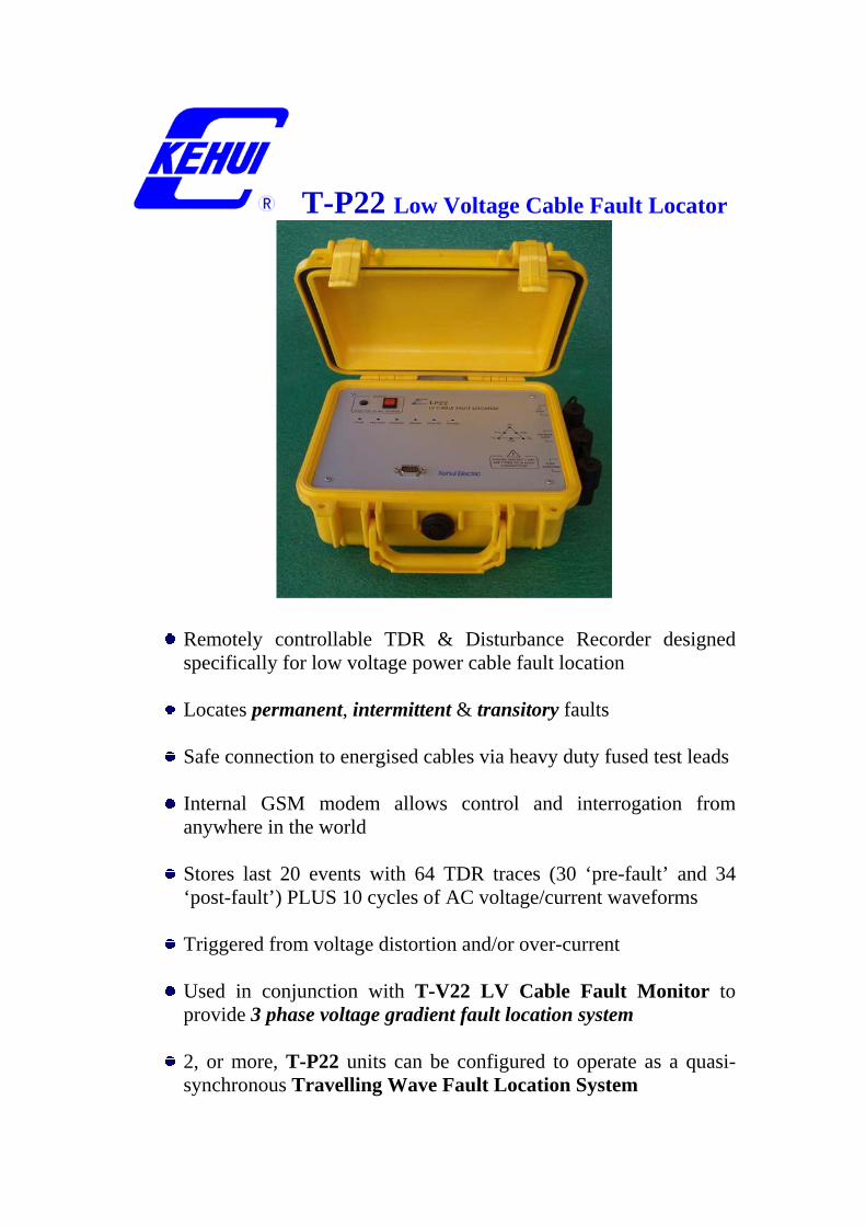
Description The Kehui T-P22 has been designed for the location of all types of low voltage cable faults but especially the difficult and troublesome intermittent fault. It can be controlled locally from a portable PC or remotely over a telephone channel (either landline or GSM). Unlike previously available TDR fault locators, the Kehui T-P22 is connected simultaneously to all 3 phases of an LV cable to allow the local or remote operator to perform TDR testing on any combination of phases. Power for the Kehui T-P22 is taken through the 3 phase test lead and the unit requires at least 1 phase to be energised. The Kehui T-P22 includes a 4 channel transient recorder (3 voltages and 1 current) which is used to acquire information about the exact nature and behaviour of intermittent faults. The signals acquired by the transient recorder are also used to detect “trigger” conditions for the TDR system based on voltage distortion and/or over-current. Voltage recordings from several of Kehui T-P22 units (and Kehui T-V22 LV Cable Fault Monitors) can be used for fault location by voltage gradient By providing total control from a remote location the Kehui T-P22 can be connected to a faulty cable by field staff who are not necessarily familiar with the analysis of TDR waveforms - the expertise in adjustment and interpretation being provided by a centrally located specialist. This becomes particularly beneficial when the equipment has to be left on-site awaiting the (re)-occurrence of an intermittent fault.
Block diagram of T-P22 Low Voltage Cable Fault Locator

T-P22 and accessories (3 phase fused test lead, CT clamp and cable & GSM antenna)
T-P22 Physical details: Length 270 mm Width 250 mm Depth 120 mm Weight 2.8 kg
Optional Accessories: P-7 Blocking Coil
Fitted with ‘Litton’ connectors for insertion in series with REZAP feeder leads to ‘isolate’ the TDR pulse from the busbar.
T-V22 LV Cable Fault Monitor
This unit is similar to the T-P22, but excludes the current transient recording channel and all TDR functions. It can be used for voltage complaint monitoring and, together with other T-V22 and/or T-P22 units, for voltage gradient fault location.
Length 210 mm Width 165 mm Depth 90 mm Weight 1.5 kg
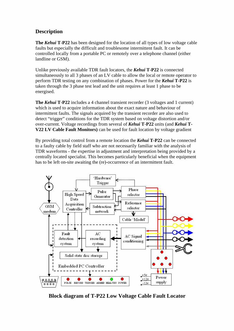
T-P2X Master - remote control, communication and analysis software
Job/Unit selection ‘Healthy’ TDR trace(pulse #1)
Arcing TDR trace (pulse #42)
Manual TDR tests
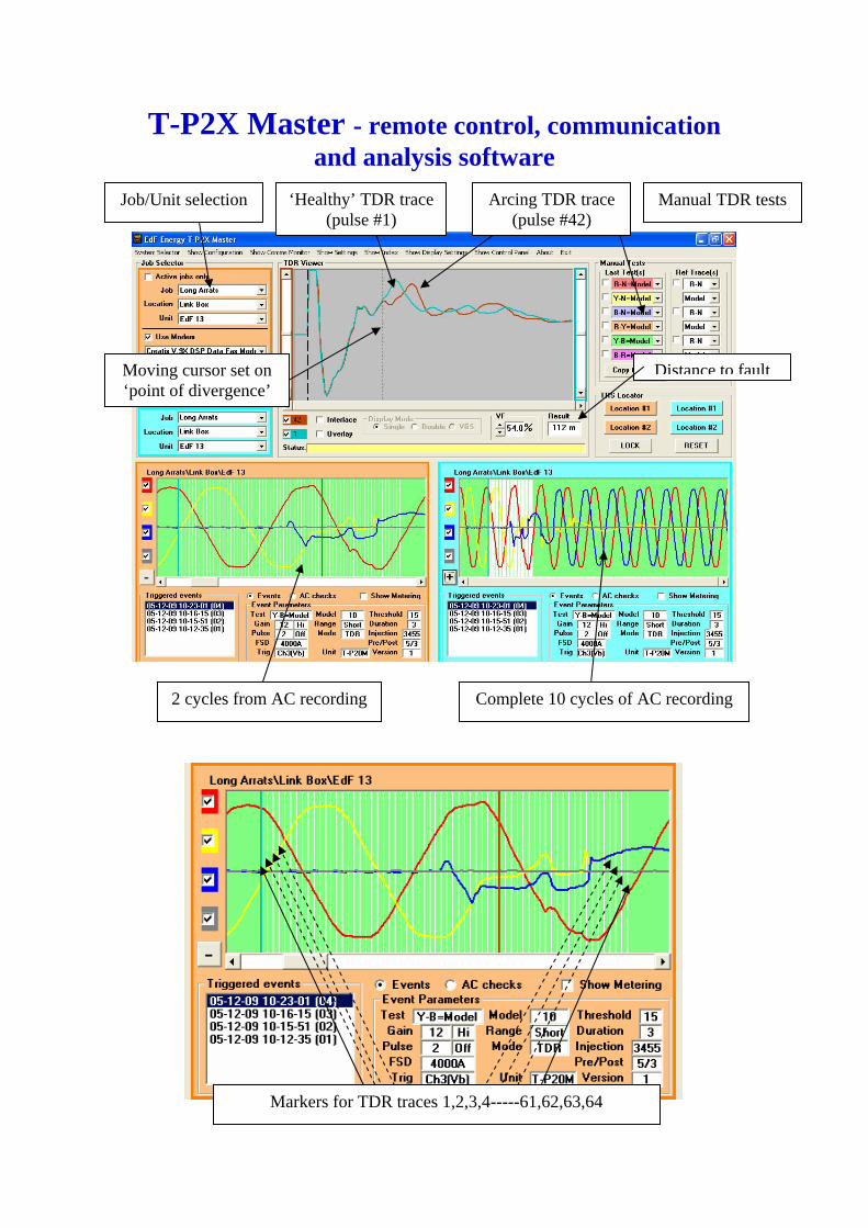
2 cycles from AC recording Complete 10 cycles of AC recording
Markers for TDR traces 1,2,3,4-----61,62,63,64
Distance to faultMoving cursor set on ‘point of divergence’
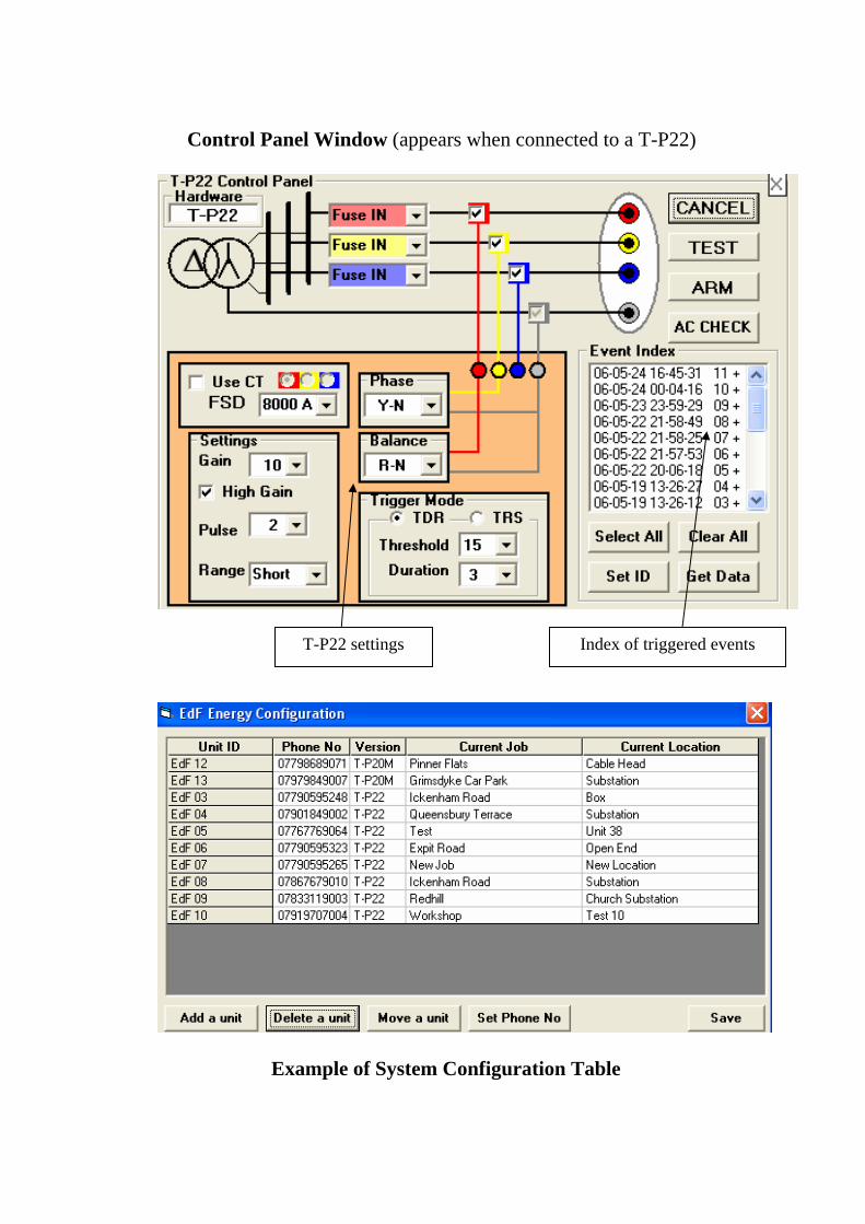
Control Panel Window (appears when connected to a T-P22)
Example of System Configuration Table
Index of triggered events T-P22 settings

Examples of simultaneous voltage recordings
Transitory Fault on Main (less than half cycle duration
Intermittent Fault on Main
Intermittent Fault on branch off Main
Voltage recording in substation Voltage recording at far end
Voltage recording in substation Voltage recording at far end
Voltage recording in substation Voltage recording at far end

TRS Fault Location Method
The high frequency acquisition section of the Kehui T-P22 can be remotely configured to operate as either a multi-pulse TDR or as a transient recorder (TRS mode). In the TRS mode, the pulse generator is enabled or disabled to make the T-P22 a Master or Slave unit respectively. Two T-P22 units are required for a Travelling Wave Fault Location System – located on either side of the fault position (generally in the substation and at the remote end).The diagrams below give a basic explanation of the method).
The lattice diagram above shows the transient recordings (green areas) of the Master and Slave units when triggered by the large high frequency signal generated by the fault (red line). The Master unit generates a continuous train of synchronising pulses (blue lines) which are too small to trigger either the Master or the Slave units.
The large fault pulses of the Master and Slave recordings are aligned and the fault is located by measuring the time interval between the injected and received synchronising pulses in the pre-trigger period of the Master and Slave unit recordings, as shown below.
Fault pulses
Injected pulses
Received pulses
Slave Unit recording
Master Unit recording
Injected pulse
Received pulse
Fault pulses
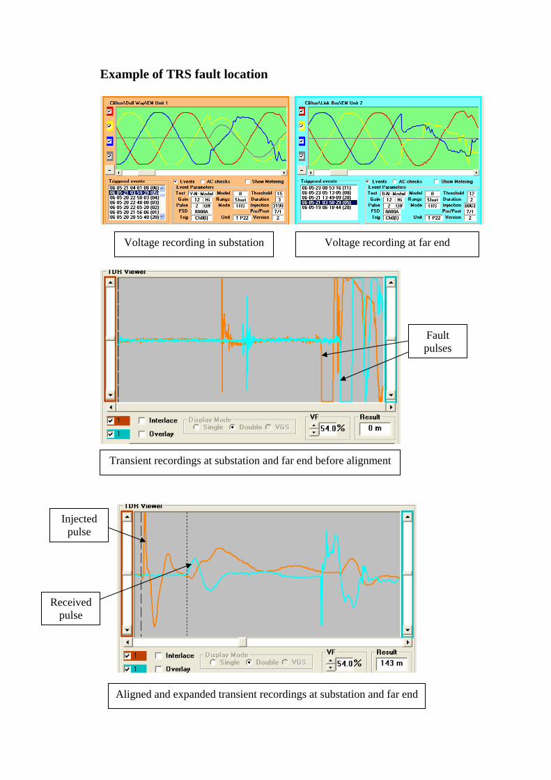
Example of TRS fault location
Voltage recording in substation Voltage recording at far end
Transient recordings at substation and far end before alignment
Aligned and expanded transient recordings at substation and far end
Injected pulse
Received pulse
Fault pulses

Notes on LV Cable Fault Location
Classification of LV Cable Faults
Transitory - irregular voltage dips Intermittent - irregular fuse operations Persistent - repetitive fuse operations Permanent - opens and welded shorts
Problems specific to LV Cable Fault Location
Multiple branches Single phase services Access to terminals Connected loads Fault behaviour
Behaviour of LV Cable Faults
Many LV cable faults ‘progress’ from the Transistory condition to the Non-Persistent and then to the Persistent condition. (Complaints of ‘flickering lights’ are an indication of the probable existence of a Transitory cable fault) During this ‘progression’ LV cable faults are unstable/non-linear and are only apparent, and therefore pre-locatable, when the cable is energised at normal working voltage. Only when a fault has ‘progressed’ to a Permanent condition, where it exhibits a stable/linear characteristic, will there be the possibility of pre-location with the cable in a de-energised state. All unstable LV cable faults require pre-conditioning in order to make them locatable. The only acceptable method of pre-conditioning for cables with consumers still connected is to re-energise at normal working voltage. When time intervals between re-energisation and the next burst of fault activity are long the most economic and convenient method of maintaining supply will be a fuse. For frequently recurring intermittent faults, and where space is available, REZAP units allow supplies to be restored quickly and may ‘assist’ in pre-conditioning the fault into a persistent or permanent condition.
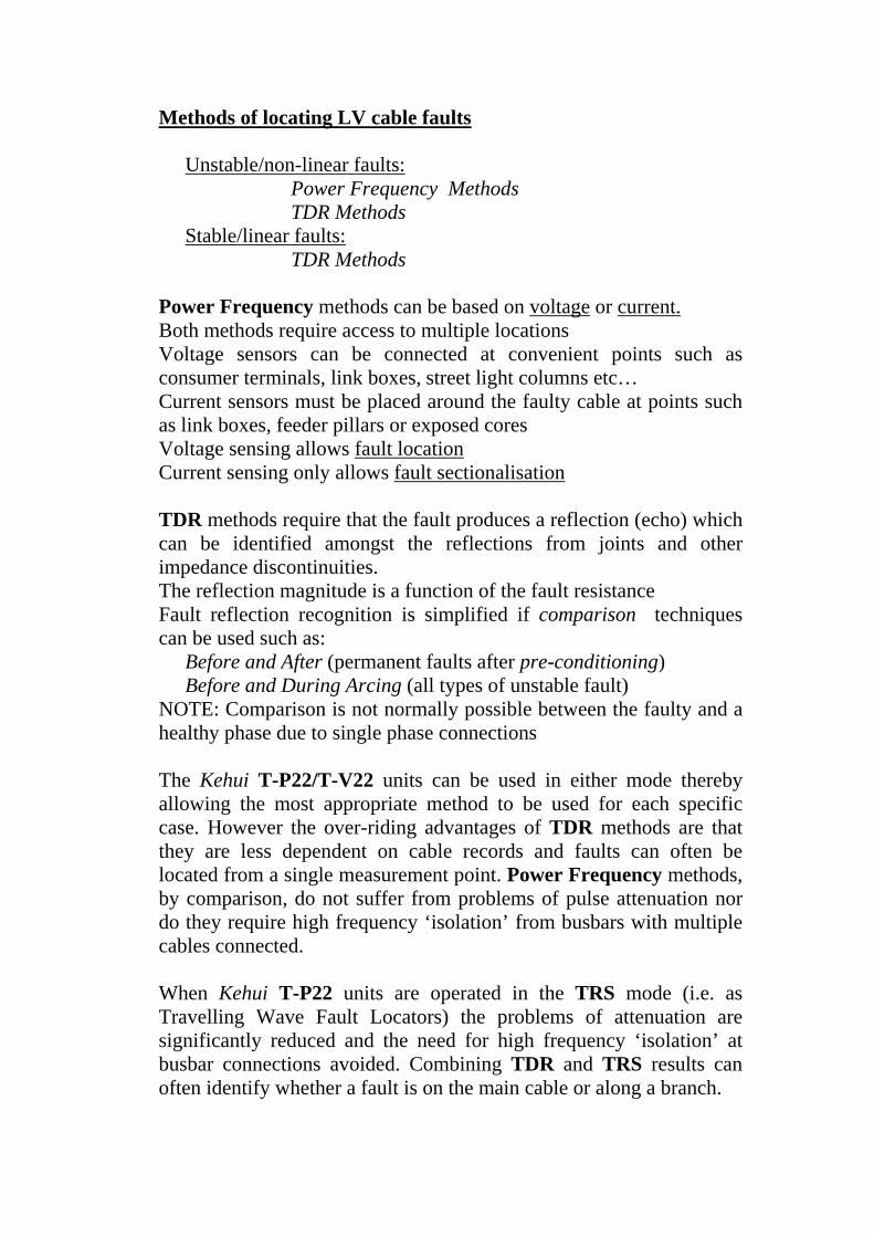
Methods of locating LV cable faults
Unstable/non-linear faults: Power Frequency Methods TDR Methods Stable/linear faults: TDR Methods
Power Frequency methods can be based on voltage or current. Both methods require access to multiple locations Voltage sensors can be connected at convenient points such as consumer terminals, link boxes, street light columns etc… Current sensors must be placed around the faulty cable at points such as link boxes, feeder pillars or exposed cores Voltage sensing allows fault location Current sensing only allows fault sectionalisation TDR methods require that the fault produces a reflection (echo) which can be identified amongst the reflections from joints and other impedance discontinuities. The reflection magnitude is a function of the fault resistance Fault reflection recognition is simplified if comparison techniques can be used such as:
Before and After (permanent faults after pre-conditioning) Before and During Arcing (all types of unstable fault)
NOTE: Comparison is not normally possible between the faulty and a healthy phase due to single phase connections The Kehui T-P22/T-V22 units can be used in either mode thereby allowing the most appropriate method to be used for each specific case. However the over-riding advantages of TDR methods are that they are less dependent on cable records and faults can often be located from a single measurement point. Power Frequency methods, by comparison, do not suffer from problems of pulse attenuation nor do they require high frequency ‘isolation’ from busbars with multiple cables connected. When Kehui T-P22 units are operated in the TRS mode (i.e. as Travelling Wave Fault Locators) the problems of attenuation are significantly reduced and the need for high frequency ‘isolation’ at busbar connections avoided. Combining TDR and TRS results can often identify whether a fault is on the main cable or along a branch.

Conclusions LV cable faults present a greater technical challenge to a DNO than HV cable faults Re-organisations within DNOs have created a need for simple equipment and procedures which can be installed by jointers Incentives imposed by the Regulator have increased the urgency to restore supplies after permanent faults and to maintain supplies by reducing the number of intermittent faults Transitory faults degrade PQ and can affect electronic equipment Observing the power frequency transients caused by LV cable faults is essential to understanding their character Fault location devices with remote control, such as the Kehui T-P22/T-V22 allow diagnosis and pre-location to be performed by centrally located specialists Pinpointing with the Fault Sniffer can be used to confirm the pre-location before commencing excavations Transitory fault phenomena can be used for condition monitoring to provide early warning of pending problems to prevent consumer interruptions and power quality complaints
Location of an intermittent fault at an outdoor substation using an early prototype of the Kehui T-P22. This fault had existed for over 6 months and was located within 24 hours of installing the T-P20.