
T HR EL 19002 ST Protection System Requirements for the ...
80
© State of NSW through Transport for NSW 2020 Protection System Requirements for the High Voltage Network T HR EL 19002 ST Standard Version 1.0 Issue date: 26 November 2020
Transcript of T HR EL 19002 ST Protection System Requirements for the ...

© State of NSW through Transport for NSW 2020
Protection System Requirements for the High Voltage Network
T HR EL 19002 ST
Standard
Version 1.0
Issue date: 26 November 2020

T HR EL 19002 ST Protection System Requirements for the High Voltage Network
Version 1.0 Issue date: 26 November 2020
© State of NSW through Transport for NSW 2020
Important message This document is one of a set of standards developed solely and specifically for use on
Transport Assets (as defined in the Asset Standards Authority Charter). It is not suitable for any
other purpose.
The copyright and any other intellectual property in this document will at all times remain the
property of the State of New South Wales (Transport for NSW).
You must not use or adapt this document or rely upon it in any way unless you are providing
products or services to a NSW Government agency and that agency has expressly authorised
you in writing to do so. If this document forms part of a contract with, or is a condition of
approval by a NSW Government agency, use of the document is subject to the terms of the
contract or approval. To be clear, the content of this document is not licensed under any
Creative Commons Licence.
This document may contain third party material. The inclusion of third party material is for
illustrative purposes only and does not represent an endorsement by NSW Government of any
third party product or service.
If you use this document or rely upon it without authorisation under these terms, the State of
New South Wales (including Transport for NSW) and its personnel does not accept any liability
to you or any other person for any loss, damage, costs and expenses that you or anyone else
may suffer or incur from your use and reliance on the content contained in this document. Users
should exercise their own skill and care in the use of the document.
This document may not be current and is uncontrolled when printed or downloaded. Standards
may be accessed from the Transport for NSW website at www.transport.nsw.gov.au
For queries regarding this document, please email the ASA at [email protected] or visit www.transport.nsw.gov.au

T HR EL 19002 ST Protection System Requirements for the High Voltage Network
Version 1.0 Issue date: 26 November 2020
© State of NSW through Transport for NSW 2020 Page 3 of 80
Standard governance
Owner: Lead Electrical Engineer, Asset Standards Authority
Authoriser: Chief Engineer, Asset Standards Authority
Approver: Executive Director, Asset Standards Authority on behalf of the ASA Configuration Control Board
Document history
Version Summary of changes
1.0 First issue.

T HR EL 19002 ST Protection System Requirements for the High Voltage Network
Version 1.0 Issue date: 26 November 2020
© State of NSW through Transport for NSW 2020 Page 4 of 80
Preface The Asset Standards Authority (ASA) is a key strategic branch of Transport for NSW (TfNSW).
As the network design and standards authority for NSW Transport Assets, as specified in the
ASA Charter, the ASA identifies, selects, develops, publishes, maintains and controls a suite of
requirements documents on behalf of TfNSW, the asset owner.
The ASA deploys TfNSW requirements for asset and safety assurance by creating and
managing TfNSW's governance models, documents and processes. To achieve this, the ASA
focuses on four primary tasks:
• publishing and managing TfNSW's process and requirements documents including TfNSW
plans, standards, manuals and guides
• deploying TfNSW's Authorised Engineering Organisation (AEO) framework
• continuously improving TfNSW’s Asset Management Framework
• collaborating with the Transport cluster and industry through open engagement
The AEO framework authorises engineering organisations to supply and provide asset related
products and services to TfNSW. It works to assure the safety, quality and fitness for purpose of
those products and services over the asset's whole-of-life. AEOs are expected to demonstrate
how they have applied the requirements of ASA documents, including TfNSW plans, standards
and guides, when delivering assets and related services for TfNSW.
Compliance with ASA requirements by itself is not sufficient to ensure satisfactory outcomes for
NSW Transport Assets. The ASA expects that professional judgement be used by competent
personnel when using ASA requirements to produce those outcomes.
About this document
This standard has been updated from RailCorp document EP 19 00 00 02 SP Protection
System Requirements for the High Voltage network, version 4.1.
EP 19 00 00 02 SP is withdrawn with the publication of this standard.
The major changes from the RailCorp version of the document include the following:
• addition of type approval requirements
• addition of protection design documentation requirements
• clarification of allocation of dc auxiliary supply for two battery locations
• installation of frame leakage on all rectifier transformers
• incorporation of TN 039:2015 for requirements of line differential schematic drawings
• incorporation of TN 028:2018 for protection requirements of harmonic filters

T HR EL 19002 ST Protection System Requirements for the High Voltage Network
Version 1.0 Issue date: 26 November 2020
© State of NSW through Transport for NSW 2020 Page 5 of 80
• update of the standard test block wiring protection relay input/output configurations
• addition of requirements for copper pilot wire schemes
• change in terminology from pilot wire to line differential
This standard is a first issue.

T HR EL 19002 ST Protection System Requirements for the High Voltage Network
Version 1.0 Issue date: 26 November 2020
© State of NSW through Transport for NSW 2020 Page 6 of 80
Table of contents 1. Introduction .............................................................................................................................................. 8
2. Purpose .................................................................................................................................................... 8 2.1. Scope ..................................................................................................................................................... 8 2.2. Application ............................................................................................................................................. 9
3. Reference documents ............................................................................................................................. 9
4. Terms and definitions ........................................................................................................................... 10
5. Type approval ........................................................................................................................................ 11
6. General protection philosophy ............................................................................................................ 12 6.1. Protection current trip settings ............................................................................................................. 12 6.2. Protection time grading settings .......................................................................................................... 12
7. Protection design documentation ....................................................................................................... 13 7.1. Content of HV protection concepts ...................................................................................................... 13 7.2. Schematic and scheme drawings ........................................................................................................ 14
8. Specific protection equipment requirements ..................................................................................... 15 8.1. Protection equipment design principles for HV switchgear ................................................................. 15 8.2. Strategic substations ........................................................................................................................... 16 8.3. Fibre optic ............................................................................................................................................ 17 8.4. Interfacing new protection schemes with existing equipment ............................................................. 17 8.5. Current transformers ............................................................................................................................ 18 8.6. Voltage transformers ........................................................................................................................... 21 8.7. Auxiliary supply (dc) ............................................................................................................................. 23 8.8. Protection relays and test blocks ......................................................................................................... 24 8.9. ACCB close inhibit ............................................................................................................................... 24 8.10. Protection alarms ............................................................................................................................. 25 8.11. Intertrip arrangements ..................................................................................................................... 25
9. Specific equipment applications.......................................................................................................... 25 9.1. 132 kV feeders ..................................................................................................................................... 25 9.2. 33 kV and 66 kV feeders ..................................................................................................................... 25 9.3. 11 kV feeders ....................................................................................................................................... 27 9.4. High voltage busbars and bus-tie cables ............................................................................................. 29 9.5. Rectifier transformer and rectifier power cubicle ................................................................................. 31 9.6. System transformers ............................................................................................................................ 32 9.7. 11 kV / 415 V transformers supplied from ring main units ................................................................... 34 9.8. 11 kV / 415 V transformers supplied from SCADA controlled ACCBs ................................................ 34 9.9. Harmonic filters .................................................................................................................................... 35 9.10. Protection SCADA alarms ............................................................................................................... 38
10. Voltage and current transducers ......................................................................................................... 38
Appendix A ACCB trip coils................................................................................................................... 39
Appendix B Two battery systems (125 V dc) – allocation of battery to protection equipment ...... 41

T HR EL 19002 ST Protection System Requirements for the High Voltage Network
Version 1.0 Issue date: 26 November 2020
© State of NSW through Transport for NSW 2020 Page 7 of 80
Appendix C Protection relay identification .......................................................................................... 42
Appendix D Standard test block wiring and input/output relay configuration ................................. 43 D.1. Line differential protection .................................................................................................................... 44 D.2. Feeder over-current and earth fault protection .................................................................................... 47 D.3. Rectifier protection ............................................................................................................................... 50 D.4. System transformer protection............................................................................................................. 54 D.5. Buszone and bus-tie protection ........................................................................................................... 60 D.6. Harmonic filter protection ..................................................................................................................... 62
Appendix E Auto re-close on high voltage feeders ............................................................................ 65
Appendix F Implementation of SCADA alarms and control ................................................................... 66
Appendix G Typical ACCB auxiliary supply arrangement .................................................................. 67
Appendix H Protection labelling guidelines......................................................................................... 69 H.1. Location of labels ................................................................................................................................. 69 H.2. Colour of labels .................................................................................................................................... 69 H.3. Format .................................................................................................................................................. 69 H.4. Content ................................................................................................................................................ 70 H.5. Examples of labels ............................................................................................................................... 70
Appendix I Standard current transformer configurations .................................................................... 73
Appendix J Metering requirements for bulk supply points ................................................................... 75 J.1. Voltage transformers ........................................................................................................................... 75 J.2. Current transformers ............................................................................................................................ 75 J.3. Current transformer and voltage transformer test results .................................................................... 76 J.4. Secondary wiring from HV switchboard to meter panel ...................................................................... 76 J.5. 240 V ac supply to metering panel ...................................................................................................... 76 J.6. Metering panel ..................................................................................................................................... 76
Appendix K Wire identification for current transformer, voltage transformer, general protection 77
Appendix L Harmonic filter connection diagram .................................................................................... 79
Appendix M Requirements for copper pilot wire schemes ................................................................. 80
T HR EL 19002 ST Protection System Requirements for the High Voltage Network
Version 1.0 Issue date: 26 November 2020
© State of NSW through Transport for NSW 2020 Page 8 of 80
1. Introduction The RailCorp high voltage (HV) alternating current (ac) networks are nominal voltages of 11 kV,
33 kV, 66 kV and 132 kV and include equipment such as HV switchboards, HV feeders, air
break switches, system transformers, rectifier transformers, and harmonic filters.
Further background information on the RailCorp HV network and general information on
RailCorp electrical infrastructure and assets is detailed in T HR EL 00001 TI RailCorp Electrical
System General Description.
2. Purpose The purpose of this document is to specify the protection requirements for the RailCorp HV
distribution network.
The prescriptive nature of this standard is to ensure:
• HV protection schemes and associated infrastructure are designed and implemented to
provide a safe and operationally reliable HV distribution network and traction supply.
• Consistency with the design of protection schemes and their implementation to enable
efficient fault finding and maintenance by operation and maintenance staff.
• Design documentation is comprehensive and accurate to enable fault finding and allow for
future modification.
Innovative approaches to HV protection that provide demonstrable value to TfNSW and our
stakeholders are encouraged, but require careful consideration in this area. Early consultation
with the Lead Electrical Engineer, ASA is essential to facilitate a concession in accordance with
T MU MD 00011 ST Concessions to ASA Requirements.
Refer to T HR EL 19001 ST Protection System Requirements for the 1500 V DC Network for
details of protection requirements for the 1500 V dc network.
2.1. Scope This document covers the protection system requirements for the RailCorp HV distribution
network for 11 kV, 33 kV, 66 kV and 132 kV system voltages.
This document covers the general design principles for protection schemes, general setting
requirements and specific requirements for protection schemes associated with the following
equipment:
• HV feeders
• HV busbars, HV bus-ties

T HR EL 19002 ST Protection System Requirements for the High Voltage Network
Version 1.0 Issue date: 26 November 2020
© State of NSW through Transport for NSW 2020 Page 9 of 80
• system transformers, rectifier transformers, distribution transformers and 11 kV auxiliary
transformers
• HV harmonic filters
This document does not include requirements for equipment used for detection and
measurement of non-electrical protection parameters (such as oil and gas sudden pressure
change, temperature measurement), other than to specify necessary interface details.
2.2. Application This document applies to all new installations and existing installations that are modified and
refurbished.
HV protection systems existing at the date of release of this document are not affected by the
requirements of this document.
3. Reference documents The following documents are cited in the text. For dated references, only the cited edition
applies. For undated references, the latest edition of the referenced document applies.
International standards
IEEE C37.2: 2008 Electrical Power System Device Function Numbers, Acronyms, and Contact
Designations
Australian standards
AS 1675 Current Transformers – Measurement and Protection
AS 2067 Substations and high voltage installations exceeding 1 kV a.c.
AS/NZS 2373 Electric cables - Twisted pair for control and protection circuits
AS 60044.1 Instrument transformers – Part 1: Current transformers
AS 60044.2 Instrument transformers – Part 2: Inductive voltage transformers
Transport for NSW standards
EP 00 00 00 15 SP Common Requirements for Electrical Power Equipment
EP 06 00 00 01 SP System Substation Battery & Battery Charger
T HR EL 00001 TI RailCorp Electrical System General Description
T HR EL 03001 ST Controls and Protection for 1500 V dc Rectification Equipment
T HR EL 11001 PR Design Technical Reviews for Electrical SCADA Equipment
T HR EL 11001 TI SCADA Standard I/O Schedule

T HR EL 19002 ST Protection System Requirements for the High Voltage Network
Version 1.0 Issue date: 26 November 2020
© State of NSW through Transport for NSW 2020 Page 10 of 80
T HR EL 11004 ST Electrical SCADA Interface Requirements
T HR EL 19001 ST Protection System Requirements for the 1500 V DC Network
T HR TE 01001 ST Communication Outdoor Cabling
T HR TE 21003 ST Telecommunications for Traction Substations and Section Huts
T MU MD 00005 GU Type Approval of Products
T MU MD 00011 ST Concessions to ASA Requirements
Transport for NSW drawings
EL0283030 Substations – 33kV Transformer Frame Leakage - Arrangement
EL0661206 Lewisham-Strathfield, Substations, 11kV Feeder 533, Line Differential Protection,
Schematic Diagram
EL0692659 Blaxland-Faulconbridge, Substations, 66kV Feeder 864, Line Differential Protection,
Schematic Diagram
Sydney Trains documents
SP D 79036 - Sydney Trains Electricity Distribution Network Bushfire Risk Management Plan
Other reference documents
Ausgrid Network Standard, ES3 Metering Installation Requirements Part A, Document NW000-
S0141, July 2018
Australian Energy Market Commission, National Electricity Rules
Endeavour Energy Metering Design Instruction, High Voltage Measurement Current and
Voltage Transformers, Document No: MET 0002 (amendment 0)
NSW Department of Planning, Industry and Environment, Service and Installation Rules of New
South Wales
TransGrid, Secondary Systems Design Standard
4. Terms and definitions The following terms and definitions apply in this document:
ACCB alternating current circuit breaker
CT current transformer
DC direct current
DCCB direct current circuit breaker
HV high voltage
IT intertrip

T HR EL 19002 ST Protection System Requirements for the High Voltage Network
Version 1.0 Issue date: 26 November 2020
© State of NSW through Transport for NSW 2020 Page 11 of 80
LV low voltage
MTA protection relay used for the multi-tripping of ACCBs; this is an automatically reset relay
with a hand reset flag
MTM protection relay used for the multi-tripping of ACCBs; this is a manually reset relay with a
hand reset flag
RMU ring main unit
RTU remote terminal unit (interface to SCADA system)
SCADA supervisory control and data acquisition system
SEF sensitive earth fault
SRR send receive relay
substation the following are locations within the RailCorp HV distribution network which are
classified as substations for the purpose of this document:
• any location that includes a high voltage ACCB
• traction substation
• high voltage switching station
• high voltage switchroom
system transformers are defined as having the following voltage ratio 132/66 kV, 132/33 kV,
66/33 kV, 66/11 kV, 33/11 kV
TBK test block
TCS trip circuit supervision
5. Type approval All high voltage (HV) protection relays (for example, electro-mechanical, numerical, multi-trip)
and relay test blocks require type approval by the ASA prior to being connected to the RailCorp
electrical network.
The type approval of HV switchgear includes the associated protection and control schematic
drawings which detail implementation of protection schemes in accordance with this standard.
Type approval processes and requirements are contained in T MU MD 00005 GU Type
Approval of Products.

T HR EL 19002 ST Protection System Requirements for the High Voltage Network
Version 1.0 Issue date: 26 November 2020
© State of NSW through Transport for NSW 2020 Page 12 of 80
6. General protection philosophy In designing the protection schemes for RailCorp’s HV distribution network, the following
principles shall be applied:
• All HV faults shall be detected and able to be cleared by two independent sets of protection
(primary and backup). HV alternating current circuit breakers (ACCBs) or fuses can be
used to clear the fault.
• The primary and backup protection schemes shall be independent (separate current
transformers (CTs), protection relays, ACCB trip coil and direct current (dc) auxiliary
supply).
• The rated continuous thermal current of the CTs shall not constrain the rating of associated
power system elements.
• Primary protection for feeders, HV busbars, HV bus-ties and system transformers shall be
implemented using unit schemes except as detailed in Section 9.3 and Section 9.4.
• The protection schemes shall be designed to eliminate or manage ‘blind spots’.
Section 6.1 and Section 6.2 provide requirements for determining protection settings.
6.1. Protection current trip settings The following principles should be applied when determining the protection current trip settings:
• The protection should be set to operate at not more than 2/3 of the minimum phase to
phase fault and not more than 2/3 of the minimum earth fault.
• The over-current protection settings should be, as far as practicable, at least 1.5 times the
maximum load current.
• Relay settings should be, as far as practicable, at least 1.5 times the highest downstream
setting.
6.2. Protection time grading settings The following principles shall be applied when determining the protection time grading:
• Fault clearing times shall be minimised.
• The protection shall be graded to ensure that the fault is cleared by the protection closest
to the fault, and that the area of interruption is minimised.

T HR EL 19002 ST Protection System Requirements for the High Voltage Network
Version 1.0 Issue date: 26 November 2020
© State of NSW through Transport for NSW 2020 Page 13 of 80
In addition, the following should be provided:
• To ensure discrimination, a 0.3 s grading margin should be provided for protection in
successive zones.
• The breaker fail time setting should be 0.2 s.
7. Protection design documentation The design documentation for HV protection schemes (excluding protection settings) and the
associated equipment consist of the following:
• A HV protection concept, which details the protection requirements. The protection concept
shall be a version controlled document that is produced by the operator and maintainer.
See Section 7.1 for details on the content of a protection concept.
• HV equipment drawings such as single line diagrams and ACCB control and protection
schematics. These are developed from the protection concept by the equipment
manufacturers and design AEO.
• Line differential scheme schematic (where required) that is produced by the design AEO.
Section 7.1 and Section 7.2 provide detail on the protection concept and schematic drawing
requirements.
7.1. Content of HV protection concepts The protection concept consists of a written document (compatible with Microsoft Word) and a
single line diagram that is developed from the approved proposed HV operating diagrams.
The protection concept diagram should contain the following:
• substation HV busbars, ACCBs, air break switches and links, voltage transformers (VTs),
transformers, location of CTs and details of the interfacing substations
• connection between protection relays and associated CTs and VTs, and connection to the
ACCB trip coils
• electrical ratings of CTs, VTs, and ratings of the HV switchgear, the HV busbar and ACCBs
• protection relay type and model
• interconnection to adjacent substations and relevant details of the HV protection scheme at
the remote substation
The HV busbar and the order of associated equipment shall match the approved operating
diagram for the location.
T HR EL 19002 ST Protection System Requirements for the High Voltage Network
Version 1.0 Issue date: 26 November 2020
© State of NSW through Transport for NSW 2020 Page 14 of 80
Existing protection equipment and interconnection is shown in blue, new equipment and
interconnection in red, and equipment to be removed in green. The busbar, ACCBs, and VTs
are shown in black.
The Word-compatible document should contain the following:
• specific protection and alarm details for each protection scheme at the location
• the protection relay type and model, specific ACCB tripped and associated trip coil, CT
ratio and class, location of CT, details on circuit breaker fail operation and corresponding
ACCBs tripped, trip circuit supervision (TCS) details
• intertrip details and communication circuit for line differential scheme
• list of alarms and indications and detail on whether hardwired or on a serial link
• specific metering requirements, details on analogues
• VT requirements, including location, size and class, associated alarms and analogues,
transducer manufacturer and model
• ACCB control, indication and protection relay supply voltage details
• protection relay models with complete part number
• scope of modifications required at interface substations if required
• relay and test block configuration when not documented or when differing from that
documented in this standard
• battery allocation when there are two battery systems in the substation
• detailed testing and commissioning requirements for protection equipment
7.2. Schematic and scheme drawings The majority of HV feeders on the RailCorp HV distribution network have a line differential
protection scheme installed.
Where a line differential scheme is installed, in addition to the schematic diagrams produced for
the individual equipment at either end of the scheme, an overall ‘line differential’ schematic
drawing is required to be produced.
The following drawings provide examples of the typical content and layout to be included on the
diagram:
• EL0661206 Lewisham-Strathfield, Substations, 11kV Feeder 533, Line Differential
Protection, Schematic Diagram
• EL0692659 Blaxland-Faulconbridge, Substations, 66kV Feeder 864, Line Differential
Protection, Schematic Diagram
T HR EL 19002 ST Protection System Requirements for the High Voltage Network
Version 1.0 Issue date: 26 November 2020
© State of NSW through Transport for NSW 2020 Page 15 of 80
When an existing line differential scheme is being modified then the associated schematics and
the line differential schematic drawing shall be modified.
If an existing line differential scheme is being modified and a line differential schematic drawing
does not exist, then the design AEO is responsible for producing a line differential schematic
drawing.
Where an additional substation is installed between two existing substations that results in the
existing line differential scheme becoming two schemes, there shall be a line differential
schematic for each individual scheme. The design AEO is responsible for producing the
schematics.
7.2.1. Content and layout of line differential scheme drawing The content of the line differential schematic diagram should typically include the following for
both ends of the scheme:
• HV busbars, associated ACCBs, air break switches (ABS) and links
• CTs (including CTs used for other protection schemes) with secondary circuitry connection
to the line differential relay; CTs to be shown in correct position and polarity identified
• VTs
• line differential relays and associated test blocks, with all connections to the relay detailed
and referenced to the equipment schematic drawings
• auxiliary supply to the line differential relay and supervisory control and data acquisition
system (SCADA) alarms
• schematic representation of the communication scheme between line differential relays
• relevant notes and an item list
8. Specific protection equipment requirements Section 8.1 through to Section 8.11 provide requirements for specific protection equipment.
8.1. Protection equipment design principles for HV switchgear To ensure the independence and integrity of protection schemes, the following principles shall
apply:
• Protection current transformers shall be connected to protection equipment only.
• Individual protection schemes shall be connected to dedicated current transformers.

T HR EL 19002 ST Protection System Requirements for the High Voltage Network
Version 1.0 Issue date: 26 November 2020
© State of NSW through Transport for NSW 2020 Page 16 of 80
• Primary and backup protection schemes shall be implemented using separate protection
relays.
• Where the primary and backup scheme trip the same HV ACCB, the following shall apply:
o The primary and backup schemes shall use separate trip coils, one trip coil for the
primary scheme, the second trip coil for the backup scheme. See Appendix A for
standard trip coil allocations and Appendix G for typical HV switchboard
arrangements.
o Each scheme shall have its own individual dc auxiliary supply from a dedicated circuit
originating at the distribution board.
• Where the substation has two dc auxiliary supplies (see Section 8.7.2) the battery
allocation for primary and backup protection schemes shall vary across the batteries for
feeders, rectifiers and buszone protection.
• SCADA monitored TCS with local indication shall be provided for all HV ACCB trip circuits.
The TCS scheme shall monitor the trip circuit with the ACCB in the open and closed
position. It should be implemented as a function of the protection relay. If the existing
protection relays do not have TCS functionality then a dedicated TCS relay shall be used.
• The auxiliary supply for each buszone and bus-tie protection scheme shall be from a
dedicated circuit originating at the distribution board. Where the protection relay is an
electromechanical type then the auxiliary supply shall be monitored with an alarm from the
monitoring relay connected to the SCADA system.
8.2. Strategic substations At strategic substations additional protection and auxiliary supplies are required to ensure the
reliability and operability of the HV distribution networks and subsequently the supply to critical
infrastructure and the 1500 V dc traction supply.
The criteria determining whether a substation is classed as a strategic substation are as follows:
• connectivity of the substation (four or more HV feeders) within the RailCorp HV distribution
network
• maximum HV fault level and the margin to the rated short-time withstand current capacity
of the switchgear installed at the substation
• criticality of the substation within the rail system
Examples of critical substations are main supply substation for city circle or rail tunnel,
substation at a rail junction, last traction substation on a radial rail line.
• complexity of the protection schemes and any resulting compromises in the protection
coordination

T HR EL 19002 ST Protection System Requirements for the High Voltage Network
Version 1.0 Issue date: 26 November 2020
© State of NSW through Transport for NSW 2020 Page 17 of 80
The protection requirements for 11 kV feeders are determined from the criticality of the 11 kV
feeder. The following is the criteria for determining whether an 11 kV feeder is classed as
critical:
• 11 kV feeders supplying underground railway stations
• 11 kV feeders installed in tunnels
• 11 kV feeders supplying installations deemed to be operationally critical (for example,
major signal boxes, operating centres)
• 11 kV feeders where it is time critical to clear the fault due to high fault levels or bushfire
hazards
8.3. Fibre optic The majority of line differential schemes installed in the RailCorp network communicate over
fibre optic and intertripping is also implemented by means of the fibre optic network.
The security of the fibre optic network is critical in ensuring the reliability of the HV protection
schemes and all fibre optic cabling shall comply with T HR TE 21003 ST Telecommunications
for Traction Substations and Section Huts and T HR TE 01001 ST Communication Outdoor
Cabling.
8.4. Interfacing new protection schemes with existing equipment Section 8.4.1 through to Section 8.4.4 provide requirements for interfacing new protection
schemes with existing equipment.
8.4.1. Multiple use of current transformers More than one protection scheme (maximum two schemes) can be connected to the same set
of CTs provided the following are satisfied:
• Installation of additional CTs is not economically feasible (for example, ACCB would have
to be replaced; additional post type CTs would be required).
• The protection schemes are not the primary and backup protection for the same
equipment.
• A failure of the CTs will not result in a piece of equipment having no protection due to an
existing compromise in the protection system.
• The output of the current transformers shall be sufficient for the burden of all the connected
protection schemes and associated equipment to ensure that each scheme operates as
required up to the available fault level.

T HR EL 19002 ST Protection System Requirements for the High Voltage Network
Version 1.0 Issue date: 26 November 2020
© State of NSW through Transport for NSW 2020 Page 18 of 80
8.4.2. Trip circuit supervision Where a new protection scheme is interfacing with existing switchgear that does not have TCS
installed, then TCS shall be implemented either as a function of the protection relay or a
dedicated TCS relay installed.
8.4.3. Breaker fail When new protection relays that have breaker fail functionality are installed in an existing
substation, the breaker fail detection shall result in the energising of a multi-trip relay. The multi-
trip relay shall trip the following:
• all the associated ACCBs on the busbar
• remote end ACCB for all feeders on the busbar
• both HV ACCBs associated with a system transformer with the breaker fail fault
The multi-trip relay can be the same relay used for buszone protection.
8.4.4. Intertrip implemented with copper pilots If a breaker fail function is associated with a feeder that has a line differential scheme utilising
copper pilots, then an intertrip can be implemented by destabilising the line differential scheme.
When destabilising the line differential scheme this shall be implemented at the line differential
relay.
8.5. Current transformers All protection and metering CTs shall comply with AS 60044.1 Instrument transformers – Part 1:
Current transformers, unless they are required to interface with existing protection schemes that
have CTs specified in accordance with AS 1675 Current Transformers – Measurement and
Protection.
• CTs shall be rigidly clamped to prevent movement under short circuit conditions.
• CTs shall safely withstand the mechanical and thermal stresses due to a short circuit equal
to the full short circuit rating of the switchgear.
• CTs shall have a minimum rated continuous thermal current of at least 150% of rated
primary current unless modified by the protection concept for the specific location.
The CTs shall be installed with polarity markings assuming supply from the busbar in all cases.
See Appendix I for requirements of CT polarity.
CTs that are not connected to a protection or metering relay shall have their secondary winding
shorted in the low voltage compartment and earthed.
Section 8.5.1 through to Section 8.5.5 provide requirements for current transformers.

T HR EL 19002 ST Protection System Requirements for the High Voltage Network
Version 1.0 Issue date: 26 November 2020
© State of NSW through Transport for NSW 2020 Page 19 of 80
8.5.1. CT rating plates and terminal markings CTs shall be provided with rating plates and terminal markings as specified in AS 60044.1. The
rating plates shall be mounted in such a manner that they are visible.
HV switchboards shall have a set of rating plates in the compartment housing the CTs and also
in the corresponding low voltage (LV) compartment.
The CT terminals shall be clearly marked to enable correct selection of the ratio. The associated
rating plate shall also be marked with the information to enable correct selection of the ratio.
The CT terminals should be readily accessible.
8.5.2. Location and order of CTs See Section 9.2.5 for CT location requirements for 33 and 66 kV feeders.
See Section 9.3.6 for CT location requirements for 11 kV feeders.
See Section 9.4.4 for CT location requirements for HV busbars and bus-ties.
See Section 9.6.6 for CT location requirements for system transformers.
See Section 9.9.11 for CT location requirements for harmonic filters.
8.5.3. Current transformers for protection Protection CTs shall be of a class entirely suitable for the connected equipment so as to give
correct operation under all service and fault conditions.
The following is the standard accuracy class:
• differential schemes – PX class
• over-current and earth fault – 10P
The rated short-time and rated short time current shall have a minimum rating equal to the
associated switchboard or ACCB.
The CT knee point should be calculated for a fault level based on the switchgear rating. Where
this is not practical due to CT physical dimensions, the maximum system fault level can be used
with a minimum 25% margin to allow for future increases in system fault levels.
8.5.4. Current transformers for metering Measurement CTs shall be of a class entirely suitable for the application as specified in
AS 60044.1 and the requirements of the National Electricity Rules.
RailCorp bulk supply feeders are class Type 2 for determining the applicable National Electricity
Rules requirements.

T HR EL 19002 ST Protection System Requirements for the High Voltage Network
Version 1.0 Issue date: 26 November 2020
© State of NSW through Transport for NSW 2020 Page 20 of 80
As a general guide the following are typical class of accuracy used in the RailCorp HV
distribution network:
• 0.5 class for general tariff metering such as supplies to shops, workshops and so on.
• 1.0 class for general measurement such as transducers and ammeters.
The measurement current transformers shall have the same ratio and rated continuous thermal
current as the associated protection CTs on the circuit.
See Appendix J for additional current transformer requirements applicable to bulk supply points.
8.5.5. Current transformer secondary wiring The following are requirements for the CT secondary wiring:
• All CT secondary wiring shall be provided with individual test links at the marshalling strip
within the respective low voltage compartment. The test links shall be Weidmuller SAKC10.
• CTs shall be earthed at one point and the earth point formed by using a proprietary cross
connection for the links being used. This single point earth shall be within the LV
compartment.
• Where multiple ratio CTs are used, the secondary wiring from all the CT taps shall be
terminated into the LV compartment to enable selecting the CT ratio within the LV
compartment.
• The CT wiring shall be connected to the associated protection relay (or revenue meter) by
means of a test block that allows isolation of the protection relay or revenue meter and
short-circuiting of the current transformer secondary. If the relay test blocks are not integral
with the relay enclosure then a test block shall be provided.
• The wiring shall be a minimum size of 2.5 mm2 and have an insulation rating of 0.6/1 kV.
Where 2.5 mm2 wiring is used it shall have a stranding of 50/0.25 mm.
• All wiring connections to the CT terminals and to the protection relay shall be made using
double grip ring type pre-insulated crimp lugs. Connections to terminals of protection relays
that a ring type lug will not physically fit shall be terminated with the manufacturers
recommended lug.
• Wiring identification shall be in accordance with Appendix K.
The CT secondary wiring insulation shall be coloured as detailed in Table 1.
Outdoor ACCBs can have black wiring from the CT terminals to the terminal block within the LV
compartment to allow for different orientation of the ACCB.

T HR EL 19002 ST Protection System Requirements for the High Voltage Network
Version 1.0 Issue date: 26 November 2020
© State of NSW through Transport for NSW 2020 Page 21 of 80
Table 1 - CT secondary wiring insulation colour
Phase Insulation colour
AØ red
BØ white
CØ blue
Neutral black
Refer to EP 00 00 00 15 SP Common Requirements for Electrical Power Equipment for details
of cable identification requirements.
8.6. Voltage transformers VTs shall be provided for all three phases and can either be a three-phase VT or three single-
phase VT.
VTs shall be manufactured and tested in accordance with AS 60044.2 Instrument transformers
– Part 2: Inductive voltage transformers. They shall have the same rated primary voltage as the
switchgear.
The number of secondary windings will depend on whether a residual protection class winding
or a metering class winding is required in addition to the protection class winding.
The voltage factor shall be 1.9 for 30 seconds.
Table 2 - VT specifications
Performance category
Rated voltage Accuracy class Rated burden (minimum) Note 1
Protection 110/√3 V 3P 50 VA
Metering 110/√3 V 0.5 50 VA
Note 1: The rated burden is required to be calculated for the specific location and
application.
The neutral point of the star connected primary shall be earthed. The neutral point of the star
connected secondary winding shall be brought out and connected to suitably insulated terminals
located in the LV compartment and earthed.
The VTs shall be protected by suitably rated ACCBs connected in the low voltage circuit as
close as possible to the transformer terminals.
HV fuse protection of VTs is not mandatory and is only required where recommended by the HV
switchboard manufacturer or manufacturer of the VT.
The requirement for a residual winding is dependent on the type of protection relay to be used.
T HR EL 19002 ST Protection System Requirements for the High Voltage Network
Version 1.0 Issue date: 26 November 2020
© State of NSW through Transport for NSW 2020 Page 22 of 80
See Appendix J for details on VT requirements for bulk supply points.
8.6.1. Voltage transformer secondary wiring The VT secondary wiring shall be coloured in accordance with the current transformer wiring
(see Table 1) with the exception of any open delta wiring, which shall be purple.
All wiring connections to CTs and to protection relays shall be made using double grip ring type
pre-insulated crimp lugs.
Terminal blocks for VT secondary wiring shall provide 4 mm sockets for the connection of test
equipment.
8.6.2. Voltage transformer alarms A three-phase, phase failure relay shall be connected to the star connected secondary winding
of the VT.
The phase failure relay shall provide a normally closed 'VOLTAGE TRANSFORMER FAIL'
alarm contact as well as visual indication.
The relay shall detect both undervoltage and negative phase sequence voltage unbalance on
the load side of the first ACCB connected to the secondary winding.
8.6.3. Voltage transformer supply to protection relays The VT supply to protection relays shall be connected to a dedicated ACCB for each protection
relay. The ACCB shall have a voltage free auxiliary contact that is connected to the SCADA
system to give a ‘FEEDER XXX DIRECTIONAL VOLTAGE FAIL' alarm.
8.6.4. Voltage transformer for 11 kV side of system transformers All 66/11 kV and 33/11 kV system transformers shall have a VT connected to the 11 kV side of
the transformer. The VT shall normally be located on the line side of the transformer 11 kV
ACCB on the 11 kV switchboard.
VTs shall be provided for all three phases and shall be single-phase VTs.
8.6.5. Voltage transformers for 66/33 kV system transformers All 66/33 kV system transformers shall have a VT connected to both the 66 kV and the 33 kV
side of the transformer. The VT shall be located on the line side of the transformer ACCB.
VTs shall be provided for all three phases and shall be single-phase VTs.

T HR EL 19002 ST Protection System Requirements for the High Voltage Network
Version 1.0 Issue date: 26 November 2020
© State of NSW through Transport for NSW 2020 Page 23 of 80
8.7. Auxiliary supply (dc) The majority of substations have an auxiliary supply of 125 V dc; other substations have a
supply of 50 V dc. The arrangement of the dc auxiliary supply is critical to the reliability of the
protection schemes.
8.7.1. Arrangement of auxiliary supply All ACCBs shall be individually supplied from the 50 V dc or 125 V dc distribution boards, with
individual supply for trip coil 1 and trip coil 2 and their associated circuitry.
In each ACCB, distinct control circuits and equipment shall be individually protected. The fuses
or circuit breaker shall be sized to ensure there is discrimination with the upstream protective
device.
The following is a list of typical ACCB circuits and equipment that would be individually
protected by fuses or circuit breakers:
• protection relays
• trip coil circuits
• close control circuit
• motor/spring charge circuits
• SCADA alarm and indication circuits
• dc/dc power supplies (for example, arc fault detection power supply, transducer power
supply)
• buszone protection schemes
See Appendix G for typical arrangement of ACCB auxiliary supply.
8.7.2. Requirement for two battery systems To ensure that integrity of the RailCorp HV distribution network is maintained when an auxiliary
supply fails, strategic substations are required to have two independent substation battery
systems.
See Section 8.2 for the criteria that defines a strategic substation.
The associated main distribution boards of the battery systems shall be capable of being
paralleled.
The two battery systems shall be of equal capacity and individually be rated for the full load and
duty cycle of the substation. Refer to EP 06 00 00 01 SP System Substation Battery & Battery
Charger for further details.

T HR EL 19002 ST Protection System Requirements for the High Voltage Network
Version 1.0 Issue date: 26 November 2020
© State of NSW through Transport for NSW 2020 Page 24 of 80
See Appendix B for specific requirements relating to protection schemes when two auxiliary
supplies are at a substation.
8.8. Protection relays and test blocks Protection relays and associated test blocks for use in the RailCorp HV electrical distribution
network require type approval. See Section 5 for further details.
All protection relays shall be flush mount and withdrawable. The auxiliary supply to the
protection relays shall be 125 V dc or 50 V dc as determined by the existing substation battery
or specified in the protection concept design.
Line differential protection relays shall be suitable for use with 1310 nm (single mode) fibre
optic.
The physical location of protection relays will depend on the type of switchgear installed.
The location should be on the low voltage compartment of the switchgear panels on indoor
switchgear or on dedicated protection panels for outdoor ACCBs, indoor 66 kV switchgear or
indoor switchgear that does not have the physical space for installing the protection relays.
The test block shall be located adjacent to the protection relay to which it is connected (right
side of protection relay).
The particular location requirements for specific relays and equipment are as follows:
• Transformer protection – differential relay, rectifier transformer frame leakage, MTA and
MTM relays shall be located on the primary protection panel.
• 66/11 kV and 33/11 kV transformers – neutral leakage relay shall be located on the 11 kV
switchgear panel.
• Buszone protection relay and associated multi-trip relay shall be located together on the
switchgear (same section) end panel.
• Bus cable tie protection relay and associated MTM relay shall be located together on either
of the associated bus-tie ACCB panels.
The standard test block wiring and input/output relay configuration are detailed in Appendix D
The labelling requirements for protection relays are detailed in Appendix H
8.9. ACCB close inhibit Where a protection operation results in an MTM relay being energised, the MTM relay shall
have normally closed contacts in the closing circuit of all the HV ACCBs that were tripped by the
MTM. This is applicable for all protection schemes.
System transformers and 11 kV/415 V transformers shall have a close inhibit contact in both the
primary and secondary ACCB closing circuits where fitted.

T HR EL 19002 ST Protection System Requirements for the High Voltage Network
Version 1.0 Issue date: 26 November 2020
© State of NSW through Transport for NSW 2020 Page 25 of 80
8.10. Protection alarms Every operation of a protection relay shall result in an individual alarm being sent to the SCADA
system and provide a local indication.
The alarm shall enable the electrical system operators to accurately identify the protection
scheme that has operated.
Refer to T HR EL 11001 TI SCADA Standard I/O Schedule for a detailed listing of SCADA
alarms.
8.11. Intertrip arrangements Optical fibre shall be used for the communication between protection relays of an intertripping
scheme.
The intertripping should be achieved utilising the line differential relays that have intertripping as
a function of the relay.
9. Specific equipment applications The protection requirements for specific equipment applications are detailed in Section 9.1
through to Section 9.10.
9.1. 132 kV feeders At the time of publication of this standard only one 132 kV feeder exists, which is a bulk supply
feeder. The protection requirements for a 132 kV bulk supply feeder are the same as detailed in
Table 3.
132 kV feeders other than bulk supply feeders are not envisaged in the future.
9.2. 33 kV and 66 kV feeders The protection requirements for 33 kV and 66 kV feeders are detailed in Section 9.2.1 through
to Section 9.2.6.
9.2.1. Standard protection schemes The schemes in Table 3 shall be provided for the protection of 33 kV and 66 kV feeders.

T HR EL 19002 ST Protection System Requirements for the High Voltage Network
Version 1.0 Issue date: 26 November 2020
© State of NSW through Transport for NSW 2020 Page 26 of 80
Table 3 – 33 kV and 66 kV feeder protection schemes
Protection scheme RailCorp network feeder Bulk supply feeder (see Note 1)
Primary protection Line differential Line differential and directional over-current and earth fault located in the RailCorp substation (looking towards supply point).
Backup protection Over-current and earth fault (may be directional if required by system configuration to achieve discrimination).
In accordance with the other electrical distributor policy.
Note 1: The exact protection requirements for bulk supply feeders can vary between
electricity distributors. TransGrid as an example require duplicate line differential
protection.
9.2.2. Primary protection All line differential schemes shall include communication circuit monitoring, which shall be
implemented as a function of the line differential relay.
9.2.3. Backup protection The backup protection on the feeder shall be an over-current and earth fault scheme, which
may be directional if required by system configuration to achieve discrimination.
This scheme shall operate by means of an ACCB and CTs that are not part of the primary
scheme.
9.2.4. Circuit breaker fail scheme The failure of an ACCB to open in response to a protection trip command shall be detected and
all possible sources of supply shall have their ACCBs tripped. A time delay of 0.2 seconds
should be provided to avoid nuisance tripping.
All ACCBs on the same busbar section as the failed ACCB shall be tripped by means of a multi-
trip relay. The buszone multi-trip relay shall be used for this purpose where fitted, otherwise the
multi-trip relay shall be an MTM relay for an indoor switchboard and an MTA relay for an
outdoor busbar.
The remote end ACCB for all the feeders on the busbar shall be tripped.
The protection relay that initiated the trip should provide the breaker fail function.
9.2.5. Location of current transformers The CTs should be located on the busbar side of the feeder ACCBs.

T HR EL 19002 ST Protection System Requirements for the High Voltage Network
Version 1.0 Issue date: 26 November 2020
© State of NSW through Transport for NSW 2020 Page 27 of 80
Where this is not practicable, the current transformers for feeder protection may be located on
the line side of the feeder ACCB. In this arrangement an intertrip shall be provided to trip the
feeder ACCB at the far end of the feeder whenever the local feeder ACCB is tripped.
See Section 8.11 for further details on intertripping.
See Appendix I for typical line differential arrangements.
9.2.6. Metering requirements Every feeder shall be provided with an ammeter and all bulk supply feeders shall be provided
with metering.
The metering on a bulk supply feeder shall be duplicated as follows:
• One set of metering for revenue checking by the operator and maintainer.
• Second set of metering that shall comply with the current National Electricity Rules, the
Service and Installation Rules of New South Wales and local electricity distributor. The
meter shall be connected to dedicated current transformers.
See Appendix J for specific current and VT requirements applicable to bulk supply points.
Details of the ammeter, metering and their connection are specified in the appropriate
switchgear standard.
9.3. 11 kV feeders The protection requirements for 11 kV feeders are detailed in Section 9.3.1 through to
Section 9.3.7.
9.3.1. Standard protection schemes The 11 kV network supplies a large variety of installations with varying degrees of operational
criticality. These installations range from underground stations, major signal boxes to minor
maintenance locations supplied from pole mounted transformers.
The criticality of the installation, accessibility of the 11 kV feeder and the fault level determines
the type of protection to be provided.
9.3.2. Primary protection See Section 8.2 for details of the definitions for determining if an 11 kV is critical and if the
primary protection needs to be a line differential scheme.
All line differential schemes shall include communication circuit monitoring, which shall be
implemented as a function of the line differential relay.
T HR EL 19002 ST Protection System Requirements for the High Voltage Network
Version 1.0 Issue date: 26 November 2020
© State of NSW through Transport for NSW 2020 Page 28 of 80
Where the primary protection scheme is not required to be a line differential scheme, the feeder
shall be protected with an over-current and earth fault scheme. The over-current and earth fault
scheme may be directional if required by system configuration to achieve discrimination.
9.3.3. Backup protection The primary protection on the feeder shall be backed up by an over-current and earth fault
scheme which may be directional if required by system configuration to achieve discrimination.
Where the primary protection is a line differential scheme, the backup over-current and earth
fault scheme can be located on the same ACCB panel; however the scheme shall operate by
means of a separate protection relay and ACCB trip coil.
Where the primary protection is not a line differential scheme, the backup over-current and
earth fault scheme shall operate by means of an ACCB and current transformers that are not
part of the primary scheme.
Where the primary protection is an over-current and earth fault scheme and is located on an
11 kV switchboard supplied directly from a transformer, a neutral leakage relay shall be used as
backup protection for 11 kV feeder earth faults.
The transformer primary over-current protection may be used to backup feeder over-current
protection. This is subject to the transformer over-current settings being suitable.
9.3.4. Sensitive earth fault Sensitive earth fault protection (SEF) shall be implemented in addition to earth fault protection
where the earth fault protection poses a high risk of not detecting a fallen overhead conductor
and the feeder is in a bushfire prone area as defined in SP D 79036 - Sydney Trains Electricity
Distribution Network Bushfire Risk Management Plan.
The scheme shall be implemented using a core balance CT which is installed around all three
conductors, with all cable screens looped back through the CT.
SEF can be implemented in the same protection relay as the over-current and earth fault
protection relay.
See Appendix E for details of the auto re-close requirements when a SEF scheme is in service.
9.3.5. Circuit breaker fail scheme The failure of an ACCB to open in response to a protection trip command shall be detected and
all ACCBs on the same busbar section as the failed ACCB shall be tripped by means of a multi-
trip relay. A time delay of 0.2 seconds should be provided to avoid nuisance tripping.
The multi-trip relay used to implement this may be the buszone multi-trip relay where fitted,
otherwise the multi-trip relay shall be an MTM relay for a switchboard.

T HR EL 19002 ST Protection System Requirements for the High Voltage Network
Version 1.0 Issue date: 26 November 2020
© State of NSW through Transport for NSW 2020 Page 29 of 80
If the feeders are protected by a line differential scheme then the appropriate remote end
ACCBs shall be tripped.
The protection relay that initiated the trip should provide this function.
9.3.6. Location of current transformers The CTs should be located on the busbar side of the feeder ACCBs.
Where this is not practicable, the current transformers for feeder protection can be located on
the line side of the feeder ACCB.
9.3.7. Metering requirements Every feeder shall be provided with an ammeter and all feeders that are a dedicated supply to
commercial premises (for example, train maintenance centres) shall be provided with metering
in accordance with the current National Electricity Rules and the Service and Installation Rules
of New South Wales where applicable.
Details of the ammeter, metering and their connection are specified in the appropriate TfNSW
switchgear standard.
9.4. High voltage busbars and bus-tie cables The protection requirements for HV busbars and bus-tie cables are detailed in Section 9.4.1
through to Section 9.4.5.
9.4.1. Primary protection for busbars All 33 kV and 66 kV indoor switchgear shall have buszone protection as the primary protection
for the busbar.
All 33 kV and 66 kV outdoor busbars shall have buszone protection as the primary protection
when the substation is not radially fed.
The requirement for buszone protection on radially fed outdoor busbars depends on the
criticality of the substation and whether a busbar fault will be detected and cleared with minimal
impact on the network. See Section 8.2 for criteria to determine whether a substation is critical.
The requirement for 11 kV indoor switchgear to have buszone protection depends on the
following location criteria:
• strategic location (see Section 8.2)
• location with high fault levels
• location where there is more than one busbar section

T HR EL 19002 ST Protection System Requirements for the High Voltage Network
Version 1.0 Issue date: 26 November 2020
© State of NSW through Transport for NSW 2020 Page 30 of 80
Where it can be demonstrated that the risk of a buszone fault on an 11 kV switchboard has
been negated by the design and construction of the switchboard, then buszone protection is not
required. The Lead Electrical Engineer, ASA shall approve this exemption.
The buszone protection for a HV switchboard can be implemented either as a high impedance
buszone protection scheme using CTs or as an arc fault detection scheme.
Arc fault detection schemes shall be type approved by the Lead Electrical Engineer, ASA as
part of the HV switchgear type approval.
Separate schemes shall be provided for each section of the busbar. All ACCBs on the
associated bus-section shall be tripped. Close inhibit shall also be implemented; see
Section 8.9 for details.
The tripping of ACCBs on an indoor switchboard shall be by means of a MTM relay. The
tripping of ACCBs on an outdoor busbar shall be by means of an MTA relay.
9.4.2. Primary protection for bus-tie cables All bus-tie cables interconnecting 11 kV, 33 kV and 66 kV indoor switchboards shall have high
impedance buszone protection as the primary protection.
The scheme shall be arranged to trip the ACCBs at both ends of the tie cable by means of a
MTM relay. Close inhibit shall also be implemented; see Section 8.9.
9.4.3. Backup protection for busbars and bus-ties The backup protection for a busbar shall be upstream over-current and earth fault protection.
Where the busbar directly interfaces with an electricity distributor then a local over-current and
earth fault protection can be the backup protection. This can be implemented in the same
directional protection relay that is looking towards the electricity distributor.
The backup protection for a bus-tie shall be a duplicate protection scheme where one of the
following applies:
• the switchboard directly interfaces with an electricity distributor
• the substation is a source of supply to underground stations or tunnels
otherwise, it shall be upstream over-current and earth fault protection.
9.4.4. Location of current transformers The current transformers for protection of the busbar should be located on the line side of all
ACCBs.
The current transformers for protection of the bus-tie cables should be located on the busbar
side of the tie ACCB.

T HR EL 19002 ST Protection System Requirements for the High Voltage Network
Version 1.0 Issue date: 26 November 2020
© State of NSW through Transport for NSW 2020 Page 31 of 80
Where the CTs for the feeder, bus-tie, or transformer circuits are not located on the busbar side
of the ACCB then:
• they shall be closest to the ACCB to have an overlap with the buszone scheme
• the buszone scheme shall also initiate tripping of the ACCBs at the far end of the feeder or
tie cable, or on the other winding of the transformer
9.4.5. Bus-tie circuit breaker fail scheme Where both primary and backup protection are installed, the failure of the ACCB to open in
response to a protection trip command shall be detected and the associated buszone MTM
relay shall be energised. A time delay of 0.2 seconds should be provided to avoid nuisance
tripping.
Only the busbar MTM associated with the ACCB that failed to open shall be energised.
9.5. Rectifier transformer and rectifier power cubicle The protection requirements for rectifier transformers and associated rectifier power cubicle are
detailed in Section 9.5.1 through to Section 9.5.5.
9.5.1. Primary protection The primary protection for the rectifier transformer and power cubicle shall be provided by an
over-current and earth fault relay. The relay shall also have the capability of programming
thermal protection for coordination with the rectifier.
The ACCB shall be tripped by means of a MTM relay for earth faults.
Refer to T HR EL 03001 ST Controls and Protection for 1500 V dc Rectification Equipment for
further detailed information on these requirements.
9.5.2. Backup protection The backup protection scheme for the rectifier transformer and power cubicle shall be provided
by a separate protection scheme, which is located in the same substation.
The protection shall be an over-current and earth fault relay. The relay shall also have the
capability of programming thermal protection for coordination with the rectifier.
The ACCB shall be tripped by means of a MTM relay for earth faults.
9.5.3. Rectifier transformer frame leakage Frame leakage protection shall be installed in addition to the primary and backup protection.
This protection shall monitor the current from the transformer tank to the substation earth
system.

T HR EL 19002 ST Protection System Requirements for the High Voltage Network
Version 1.0 Issue date: 26 November 2020
© State of NSW through Transport for NSW 2020 Page 32 of 80
A dedicated instantaneous relay and test block shall be installed in the same location as the
primary and backup protection relays for the rectifier transformer.
Refer to EL0283030 Substations – 33kV Transformer Frame Leakage - Arrangement for further
details.
9.5.4. Circuit breaker fail scheme The failure of the ACCB to open in response to a protection trip command shall be detected and
the associated buszone MTM relay shall be energised. A time delay of 0.2 seconds should be
provided to avoid nuisance tripping.
9.5.5. Protection interface requirements Refer to T HR EL 03001 ST for further detailed information on the protection interface
requirements and requirements for non-electrical protection devices associated with the rectifier
transformer and rectifier power cubicle.
9.6. System transformers All system transformers shall have transformer differential as the primary protection and
over-current and earth leakage as the backup protection.
Refer to the ASA transformer equipment specification for details of non-electrical protective
devices installed on the transformer.
The protection requirements for system transformers are detailed in Section 9.6.1 through to
Section 9.6.6.
9.6.1. Primary protection The transformer differential scheme shall be arranged to trip both the primary and secondary
ACCBs.
The tripping of the ACCBs shall be by means of a multi-trip relay. If the transformer is cable
connected on both the primary and secondary (terminals and bushings not exposed) then the
multi-trip relay shall be a MTM relay; otherwise it should be an MTA relay.
9.6.2. Backup protection Over-current and earth fault shall be provided as the backup transformer protection and shall
trip both the primary and secondary ACCBs by means of a multi-trip relay.
If the transformer is cable connected (terminals and bushings not exposed) then the multi-trip
relay shall be a MTM relay for earth faults.

T HR EL 19002 ST Protection System Requirements for the High Voltage Network
Version 1.0 Issue date: 26 November 2020
© State of NSW through Transport for NSW 2020 Page 33 of 80
Over-current protection shall trip the ACCBs by means of an MTA relay regardless of the HV
transformer connection configuration.
Three-phase over-current protection shall be provided on the low voltage side of the transformer
as backup protection to the outgoing feeder over-current protection.
9.6.3. Circuit breaker fail scheme The failure of an ACCB to open in response to a backup protection trip command shall be
detected and the associated buszone multi-trip relay energised. A time delay of 0.2 seconds
should be provided to avoid nuisance tripping.
9.6.4. Neutral leakage On 66/11 kV and 33/11 kV system transformers, neutral leakage shall be provided as backup
protection to 11 kV feeder earth faults. The scheme shall trip both the primary and secondary
ACCB of the transformer by means of a MTA relay. The neutral leakage relay shall be located
on the 11 kV switchboard.
9.6.5. Non-electrical protection devices System transformers are fitted with non-electrical protection devices which interface with the
protection relays to trip the ACCBs as follows:
• Buchholz relays shall trip both the primary and secondary ACCBs by means of a MTM
relay
• pressure relief devices shall trip both the primary and secondary ACCBs by means of a
MTM relay
• temperature monitoring, first stage shall be an alarm and second stage shall trip both the
primary and secondary ACCBs by means of a MTM relay
The exact non-electrical protection device will depend on the type of transformer.
9.6.6. Location of current transformers The CTs for the differential protection should be located on the busbar side of both the primary
and secondary ACCBs. Where this is not practicable, the CTs for transformer protection can be
located on the transformer side of the transformer ACCB.
The current transformer for neutral leakage protection shall be located on the neutral to earth
connection on the transformer.

T HR EL 19002 ST Protection System Requirements for the High Voltage Network
Version 1.0 Issue date: 26 November 2020
© State of NSW through Transport for NSW 2020 Page 34 of 80
9.7. 11 kV / 415 V transformers supplied from ring main units All 11 kV distribution transformers (200 kVA and above up to 1 MVA) that are supplied by
means of an ACCB from a ring main unit (RMU) shall be protected by a protection relay.
Transformers less than 200 kVA shall be protected by fuses.
9.8. 11 kV / 415 V transformers supplied from SCADA controlled ACCBs The requirements detailed in Section 9.8.1 to Section 9.8.6 apply to 11 kV / 415 V transformers
supplied from SCADA controlled ACCBs, except those SCADA controlled ACCBs in a RMU.
9.8.1. Standard protection schemes All 11 kV transformers 1 MVA or greater in size shall have transformer differential as the primary
protection and over-current and earth leakage as the backup protection.
Transformers that are less than 1 MVA shall have over-current and earth leakage as the
primary protection.
Transformer differential schemes may be used on smaller transformers where required to
ensure that the transformer protection grades over the LV protection.
9.8.2. Primary protection The primary protection scheme shall trip both the primary and secondary ACCBs by means of a
multi-trip relay.
If the transformer is cable connected on both the primary and secondary (terminals and
bushings not exposed) then the multi-trip relay shall be a MTM relay; otherwise it should be an
MTA relay.
9.8.3. Backup protection Over-current and earth fault shall be provided as the backup transformer protection and shall
trip both the primary and secondary ACCBs by means of a multi-trip relay.
If the transformer is cable connected on both the primary and secondary (terminals and
bushings not exposed) then the multi-trip relay shall be a MTM relay; otherwise it should be an
MTA relay.
Over-current protection shall trip the ACCBs by means of an MTA relay regardless of the HV
transformer connection configuration.

T HR EL 19002 ST Protection System Requirements for the High Voltage Network
Version 1.0 Issue date: 26 November 2020
© State of NSW through Transport for NSW 2020 Page 35 of 80
The backup protection scheme is not required to detect faults on the LV winding of a distribution
transformer or the LV cables.
9.8.4. Circuit breaker fail scheme The failure of an ACCB to open in response to a backup protection trip command shall be
detected and the associated buszone multi-trip relay energised. A time delay of 0.2 seconds
should be provided to avoid nuisance tripping.
9.8.5. Non-electrical protection devices Transformers are fitted with non-electrical protection devices which interface with the protection
relays to trip the ACCBs as follows:
• Buchholz relays shall trip both the primary and secondary ACCBs by means of a MTM
relay
• pressure relief devices shall trip both the primary and secondary ACCBs by means of a
MTM relay
• temperature monitoring, first stage shall be an alarm and second stage shall trip both the
primary and secondary ACCBs by means of a MTM relay
The exact non-electrical device depends on the type of transformer.
9.8.6. Location of current transformers The CTs for the differential protection should be located on the busbar side of both the primary
and secondary ACCBs. Where this is not practicable, the CTs for transformer protection can be
located on the transformer side of the transformer ACCB.
9.9. Harmonic filters The protection requirements for harmonic filters are detailed in Section 9.9.1 through to Section
9.9.14.
See Appendix L for a general connection diagram.
9.9.1. Primary protection The primary protection for the harmonic filter shall be provided by an over-current and earth
fault protection relay and two specialised harmonic filter protection relays for the protection of
the reactor and capacitor banks.
The auxiliary capacitor is not protected; instead it shall be rated conservatively to ensure that it
does not fail under any reasonable operating conditions.
T HR EL 19002 ST Protection System Requirements for the High Voltage Network
Version 1.0 Issue date: 26 November 2020
© State of NSW through Transport for NSW 2020 Page 36 of 80
Similarly, the damping resistor is not supplied with over-current protection as it shall be very
conservatively rated.
9.9.2. Capacitor bank protection The capacitor banks shall be protected by an over-current and earth fault protection relay to
detect filter bank internal short circuits and earth fault currents.
9.9.3. Phase undervoltage protection Phase undervoltage protection shall also be provided by the over-current and earth fault relay to
trip the harmonic filter ACCB. A timer relay shall be initiated to inhibit re-energisation of the
harmonic filter before the capacitors are discharged to a safe voltage.
9.9.4. Repetitive peak overvoltage protection Repetitive peak overvoltage protection shall be provided by a specialised harmonic filter
protection relay for the capacitor banks. This relay shall withstand a root mean square (rms)
sinusoidal voltage of 110% rated voltage at rated frequency for extended periods, or higher
voltages for shorter periods as described by the temporary overvoltage withstand curves in the
relevant ANSI and IEC recommendations.
9.9.5. Thermal over-current protection Thermal over-current protection shall be provided by a specialised harmonic filter protection
relay to protect the harmonic filter components from excessive temperature rise as limited by
adjustable threshold settings on the relay.
9.9.6. Unbalance protection Protection of the capacitor banks is achieved mainly by means of unbalance protection. The
unbalance protection shall be provided by two specialised harmonic filter protection relays to
protect the capacitor banks that are connected in a double star point and H-bridge
configurations.
The unbalance protection shall be required to raise an alarm in the event of a failure of one or
more capacitor elements and to trip the ACCB in the event of a failure of two or more elements.
The protection shall prevent overvoltage stressing of capacitor units.
9.9.7. Double star point unbalance protection Double star point unbalance protection shall be provided by a specialised harmonic filter
protection relay to monitor the flow of current between the double star points of the harmonic
filter capacitor banks in the event of component failure.

T HR EL 19002 ST Protection System Requirements for the High Voltage Network
Version 1.0 Issue date: 26 November 2020
© State of NSW through Transport for NSW 2020 Page 37 of 80
The time delay for trip shall be the shortest possible to avoid serious damage in case of element
breakdown.
9.9.8. H-bridge unbalance protection H-bridge unbalance protection shall be provided by a separate specialised harmonic filter
protection relay for each phase of the capacitor bank.
9.9.9. Backup protection Backup protection shall be provided by an upstream over-current and earth fault protection
relay.
9.9.10. Breaker fail scheme The failure of the ACCB to open in response to a protection trip command shall be detected and
the associated buszone MTM relay shall be energised. A time delay of 0.2 seconds should be
provided to avoid nuisance tripping.
The protection relays should provide this function.
9.9.11. Location of current transformers The preferred locations of the protection current transformers (CTs) are as follows:
• over-current and earth fault – busbar side of the ACCB
• thermal over-current – busbar side of the ACCB
• repetitive peak overvoltage (shared the same CT as thermal over-current) – busbar side of
the ACCB
The preferred locations of the unbalance protection CTs in the capacitor banks are as follows:
• H-bridge unbalance – reference A phase CT on feeder side of ACCB (CTs on the H-bridge)
• Double star unbalance – reference A, B and C phase CTs on feeder side of ACCB (CTs on
the star point)
9.9.12. Voltage transformer A VT shall be provided for all three phases and can either be a three-phase VT or three single-
phase VTs.
VTs shall be connected to an over-current and earth fault protection relay to provide phase
undervoltage protection.
The VTs should have an accuracy class 3P and rated burden 45 VA or 50 VA. A dedicated VT
may not be required and where available, inputs from the existing bus section VT may be used.
T HR EL 19002 ST Protection System Requirements for the High Voltage Network
Version 1.0 Issue date: 26 November 2020
© State of NSW through Transport for NSW 2020 Page 38 of 80
9.9.13. Metering requirements The harmonic filter shall be provided with a current transformer, a current transducer and an
ammeter for local and remote metering only on B-phase.
9.9.14. Access interlock To prevent personnel from accessing the harmonic filter prior to the capacitors being discharged
to less than 50 V ac, a timer circuit and key lock switch arrangement shall be employed. The
timer circuit is also used to inhibit re-closure of the harmonic filter HV ACCB after an open or trip
operation.
The timer setting shall be based on the time constant of the filter plus an appropriate safety
margin to allow the capacitors to discharge to less than 50 V ac.
If the mechanical key lock is not available, then electro-mechanical interlocking shall be
employed between electro-mechanical key lock release and a timer relay.
Additional safety requirements may be required to ensure that the capacitor banks are
discharged to less than 50 V ac before releasing the locks.
The interlock shall be implemented on the harmonic filter switchgear panel and shall not rely on
the SCADA system to inhibit control of the harmonic filter HV ACCB during capacitor discharge.
9.10. Protection SCADA alarms Protection alarms are a critical piece of information that shall be conveyed to the SCADA
system for use by the electrical system operator and recorded as engineering information.
The protection SCADA alarm requirements are detailed in T HR EL 11001 TI.
See Appendix F for details on protection alarms that are required to be hardwired.
10. Voltage and current transducers Transducers that are to be used to provide the SCADA system with current and voltage
information relating to the HV network shall be in accordance with the requirements of T HR EL
11004 ST Electrical SCADA Interface.
Current transducers shall be connected to metering class CT and shall not be connected to
protection CTs.

T HR EL 19002 ST Protection System Requirements for the High Voltage Network
Version 1.0 Issue date: 26 November 2020
© State of NSW through Transport for NSW 2020 Page 39 of 80
Appendix A ACCB trip coils Table 4 details the protection scheme and associated ACCB trip coil to which the protection
relay is connected. The relevant section in this standard specifies whether the trip is by means
of a multi-trip relay and the associated type.
An approved protection concept design for individual locations documents the specific
requirements for that location.
See Section 9.2.1 for additional requirements relating to breaker fail schemes and supply
points.
Table 4 – ACCB trip coil allocation
Equipment Protection scheme Trip coil number Notes
Feeder protection Line differential 1
Over-current and earth fault
2 c
Intertrip 1
Buszone and bus-tie Busbar protection 2 a
Cable bus-tie protection
1 b
66/33 kV system transformers
Differential 1 d, e
66 kV over-current and earth fault
2 e
33 kV over-current and earth fault
2 e
Tx overpressure, Buchholz, tx winding temp
1 e
66/11 kV and 33/11 kV system transformers
Differential 1 d, e
33 kV over-current 2 e
Neutral leakage 2 e
11 kV over-current 2 e
Tx overpressure, Buchholz, tx winding temp
1 e
Harmonic filter Over-current and earth fault
1
Phase undervoltage 1
Repetitive peak overvoltage
2
Thermal over-current 2
Double star point unbalance
2

T HR EL 19002 ST Protection System Requirements for the High Voltage Network
Version 1.0 Issue date: 26 November 2020
© State of NSW through Transport for NSW 2020 Page 40 of 80
Equipment Protection scheme Trip coil number Notes
H-bridge unbalance 2
11 kV/415 V transformers
Differential 1 e, g
Over-current 2 c, g
Rectifier transformers (primary protection)
Instantaneous over-current
1 f
Earth fault 1 f
Rectifier transformers (backup protection)
Instantaneous over-current
2 f
Earth fault 2 f
Rectifier transformer MTM and frame leakage
1
Notes:
a) The operation of the buszone protection energises a multi-trip relay, which trips all
ACCBs on the section of the busbar. The trip coil number applies to all ACCBs that are
tripped on the associated busbar section. See Section 9.4 for requirements on MTM or
MTA trip.
b) When there is duplicate protection on the bus-tie cable the duplicate scheme shall trip
the ACCBs by means of trip coil 2 (by means of an MTM).
c) If there is no differential protection, then the over-current protection shall trip by means
of trip coil 1.
d) Trip coil number applies to both ACCBs (for example, 33 kV and 11 kV, 66 kV and
33 kV).
e) See Section 9.6 for requirements on MTM or MTA trip.
f) See Section 9.6 for requirements on MTM or MTA trip.
g) See Section 9.8 for requirements on MTM or MTA trip.

T HR EL 19002 ST Protection System Requirements for the High Voltage Network
Version 1.0 Issue date: 26 November 2020
© State of NSW through Transport for NSW 2020 Page 41 of 80
Appendix B Two battery systems (125 V dc) – allocation of battery to protection equipment
When allocating the battery for substations with two battery systems the principles in this
appendix should be applied.
The battery allocation should be determined with the substation and HV networks in the normal
operating state.
See Appendix G for details of typical auxiliary supply arrangement to HV ACCBs. These
diagrams illustrate the principle; however, detailed design is required to ensure the following
principles are applied:
• The loss of one battery should not result in the loss of all the primary protection schemes
on similar equipment.
• The protection relay should be supplied from the same battery as the HV ACCB trip coil
that it energises. See Appendix A for details on protection and associate HV ACCB trip coil.
This is not generally applicable to buszone and bus-tie protection schemes.
• HV feeders - The battery should be alternated to ensure that not all feeder primary
protection is sourced from the one battery.
• Busbar protection - The battery should be alternated to buszone protection schemes.
• Rectifiers – The battery should be alternated to ensure that not all rectifier primary
protection is sourced from the one battery.
• Systems transformers – where there are multiple system transformers the battery should
be alternated to ensure that not all system transformer primary protection is sourced from
the one battery.
• HV bus-tie - The battery should be alternated to ensure that not all bus-tie protection is
sourced from the one battery.
• 1500 V DCCBs – The battery should be allocated to consider operational impacts.
• SCADA alarms – The supply to SCADA alarms shall be from battery 1.
In the case of two battery systems, the equipment should be connected across the two battery
systems to obtain balanced loads as close as possible.

T HR EL 19002 ST Protection System Requirements for the High Voltage Network
Version 1.0 Issue date: 26 November 2020
© State of NSW through Transport for NSW 2020 Page 42 of 80
Appendix C Protection relay identification Device numbers and functions should be in accordance with IEEE C37.2: 2008 Electrical Power
System Device Function Numbers, Acronyms, and Contact Designations. The detailed
implementation shall be as set out in accordance with Table 5.
Table 5 – Protection relay identification
Relay identifier Description
27/HF Phase undervoltage protection
49/HF Thermal over-current protection
50/L Instantaneous over-current relay (feeder)
50/T Instantaneous over-current relay (transformer)
50/T1 Instantaneous over-current relay – Backup (transformer)
51/L Inverse time over-current relay
59/HF Repetitive peak overvoltage protection
60/HF Double star point unbalance protection
60/HF H-bridge unbalance protection
63 Buchholz relay
64 Instantaneous earth fault relay
64FL Transformer frame leakage relay
67 Directional over-current relay
67/L Directional over-current relay (feeder)
87/B Differential protective relay (busbar – high impedance)
87/BT Differential protective relay (bus-tie cable – high impedance)
87/L Differential protective relay (feeder - line differential scheme)
87/T Differential protective relay (transformer)
MTA Multi trip automatic reset relay
MTM Multi trip manual reset relay
SRR Send receive relay
TBK1,2 Test block
TCS Trip circuit supervisory relay
SEF Sensitive earth fault

T HR EL 19002 ST Protection System Requirements for the High Voltage Network
Version 1.0 Issue date: 26 November 2020
© State of NSW through Transport for NSW 2020 Page 43 of 80
Appendix D Standard test block wiring and input/output relay configuration
The test block, protection relay input and output configurations in this appendix are provided to
ensure consistency with the programming of numerical relays, the testing procedures for
periodic maintenance and the production of standard designs.
The configurations do not determine the requirement for a particular protection function, but
detail the test block connections and output or input relay if that function is required to be
implemented.
To connect alarms by means of the test block or to connect spare output relays to the test block
is not a general practice. The test block shall be located adjacent to the protection relay it is
associated with.
Where the alarms are conveyed by the serial communications of the relay it is not required to
program the relay output contacts for the same alarms.
Any deviations from the standard configuration shall be approved by the Lead Electrical
Engineer, ASA.
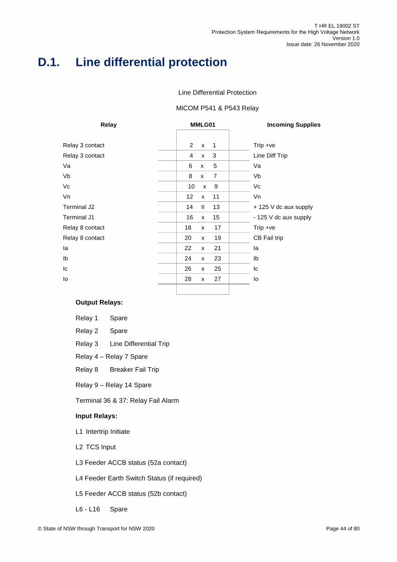
T HR EL 19002 ST Protection System Requirements for the High Voltage Network
Version 1.0 Issue date: 26 November 2020
© State of NSW through Transport for NSW 2020 Page 44 of 80
D.1. Line differential protection
Line Differential Protection
MiCOM P541 & P543 Relay
Relay MMLG01 Incoming Supplies
Relay 3 contact 2 x 1 Trip +ve
Relay 3 contact 4 x 3 Line Diff Trip
Va 6 x 5 Va
Vb 8 x 7 Vb
Vc 10 x 9 Vc
Vn 12 x 11 Vn
Terminal J2 14 II 13 + 125 V dc aux supply
Terminal J1 16 x 15 - 125 V dc aux supply
Relay 8 contact 18 x 17 Trip +ve
Relay 8 contact 20 x 19 CB Fail trip
Ia 22 x 21 Ia
Ib 24 x 23 Ib
Ic 26 x 25 Ic
Io 28 x 27 Io
Output Relays:
Relay 1 Spare
Relay 2 Spare
Relay 3 Line Differential Trip
Relay 4 – Relay 7 Spare
Relay 8 Breaker Fail Trip
Relay 9 – Relay 14 Spare
Terminal 36 & 37: Relay Fail Alarm
Input Relays:
L1 Intertrip Initiate
L2 TCS Input
L3 Feeder ACCB status (52a contact)
L4 Feeder Earth Switch Status (if required)
L5 Feeder ACCB status (52b contact)
L6 - L16 Spare

T HR EL 19002 ST Protection System Requirements for the High Voltage Network
Version 1.0 Issue date: 26 November 2020
© State of NSW through Transport for NSW 2020 Page 45 of 80
Line Differential Protection
MiCOM P521 Relay
Relay MMLG01 Incoming Supplies
Relay 1 contact 2 x 1 Trip +ve
Relay 1 contact 4 x 3 Line Diff Trip
Spare 6 x 5 Spare
Spare 8 x 7 Spare
Spare 10 x 9 Spare
Spare 12 x 11 Spare
Terminal 33 14 II 13 + 125 V dc aux supply
Terminal 34 16 x 15 - 125 V dc aux supply
Relay 8 contact 18 x 17 Trip +ve
Relay 8 contact 20 x 19 CB Fail trip
Ia 22 x 21 Ia
Ib 24 x 23 Ib
Ic 26 x 25 Ic
Io 28 x 27 Io
Output Relays:
Relay 1 Line Differential Trip
Relay 2 TCS Alarm
Relay 3 Line Differential Alarm
Relay 4 Comms Fail Alarm
Relay 5 Spare
Relay 6 Breaker Fail Alarm
Relay 7 Spare
Relay 8 Breaker Fail Trip
Terminal 36 & 37: Relay Fail Alarm
Input Relays:
L 1 Intertrip Initiate
L2 TCS Input
L3 – L5 Spare

T HR EL 19002 ST Protection System Requirements for the High Voltage Network
Version 1.0 Issue date: 26 November 2020
© State of NSW through Transport for NSW 2020 Page 46 of 80
Line Differential Protection
Siemens 7SD610 Relay
Relay MMLG01 Incoming Supplies
Relay BO4 contact 2 x 1 Trip +ve
Relay BO4 contact 4 x 3 Line Diff Trip
Spare 6 x 5 Spare
Spare 8 x 7 Spare
Relay BO5 contact 10 x 9 Trip +ve
Relay BO5 contact 12 x 11 Intertrip Trip
Terminal F2 14 II 13 + 125 V dc aux supply
Terminal F1 16 x 15 - 125 V dc aux supply
Relay BO3 contact 18 x 17 Trip +ve
Relay BO3 contact 20 x 19 CB Fail trip
Ia 22 x 21 Ia
Ib 24 x 23 Ib
Ic 26 x 25 Ic
Io 28 x 27 Io
Input Relays:
BI1 - BI4 Spare
BI5 - TCS input
BI6 – ACCB status
BI7 – IT initiate send
Output Relays:
BO1 Line Diff Trip alarm
BO2 Comms fail alarm
BO3 Remote ACCB indication
BO4 Line Differential & Intertrip Receive Trip
BO5 Breaker Fail Trip
Note:
At some locations alarms are by means of DNP3.0 communication.
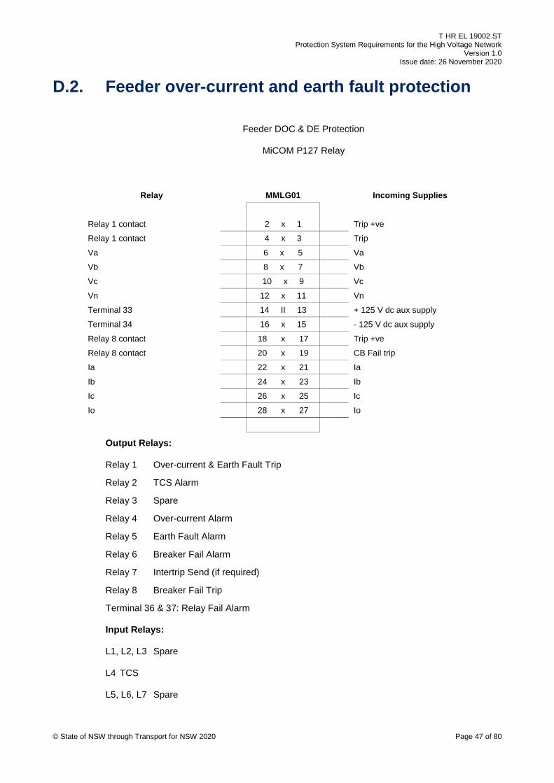
T HR EL 19002 ST Protection System Requirements for the High Voltage Network
Version 1.0 Issue date: 26 November 2020
© State of NSW through Transport for NSW 2020 Page 47 of 80
D.2. Feeder over-current and earth fault protection
Feeder DOC & DE Protection
MiCOM P127 Relay
Relay MMLG01 Incoming Supplies
Relay 1 contact 2 x 1 Trip +ve
Relay 1 contact 4 x 3 Trip
Va 6 x 5 Va
Vb 8 x 7 Vb
Vc 10 x 9 Vc
Vn 12 x 11 Vn
Terminal 33 14 II 13 + 125 V dc aux supply
Terminal 34 16 x 15 - 125 V dc aux supply
Relay 8 contact 18 x 17 Trip +ve
Relay 8 contact 20 x 19 CB Fail trip
Ia 22 x 21 Ia
Ib 24 x 23 Ib
Ic 26 x 25 Ic
Io 28 x 27 Io
Output Relays:
Relay 1 Over-current & Earth Fault Trip
Relay 2 TCS Alarm
Relay 3 Spare
Relay 4 Over-current Alarm
Relay 5 Earth Fault Alarm
Relay 6 Breaker Fail Alarm
Relay 7 Intertrip Send (if required)
Relay 8 Breaker Fail Trip
Terminal 36 & 37: Relay Fail Alarm
Input Relays:
L1, L2, L3 Spare
L4 TCS
L5, L6, L7 Spare
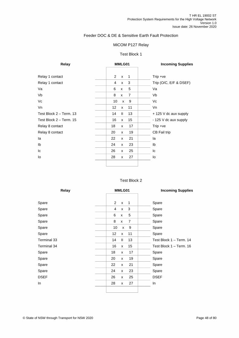
T HR EL 19002 ST Protection System Requirements for the High Voltage Network
Version 1.0 Issue date: 26 November 2020
© State of NSW through Transport for NSW 2020 Page 48 of 80
Feeder DOC & DE & Sensitive Earth Fault Protection
MiCOM P127 Relay
Test Block 1
Relay MMLG01 Incoming Supplies
Relay 1 contact 2 x 1 Trip +ve
Relay 1 contact 4 x 3 Trip (O/C, E/F & DSEF)
Va 6 x 5 Va
Vb 8 x 7 Vb
Vc 10 x 9 Vc
Vn 12 x 11 Vn
Test Block 2 – Term. 13 14 II 13 + 125 V dc aux supply
Test Block 2 – Term. 15 16 x 15 - 125 V dc aux supply
Relay 8 contact 18 x 17 Trip +ve
Relay 8 contact 20 x 19 CB Fail trip
Ia 22 x 21 Ia
Ib 24 x 23 Ib
Ic 26 x 25 Ic
Io 28 x 27 Io
Test Block 2
Relay MMLG01 Incoming Supplies
Spare 2 x 1 Spare
Spare 4 x 3 Spare
Spare 6 x 5 Spare
Spare 8 x 7 Spare
Spare 10 x 9 Spare
Spare 12 x 11 Spare
Terminal 33 14 II 13 Test Block 1 – Term. 14
Terminal 34 16 x 15 Test Block 1 – Term. 16
Spare 18 x 17 Spare
Spare 20 x 19 Spare
Spare 22 x 21 Spare
Spare 24 x 23 Spare
DSEF 26 x 25 DSEF
In 28 x 27 In
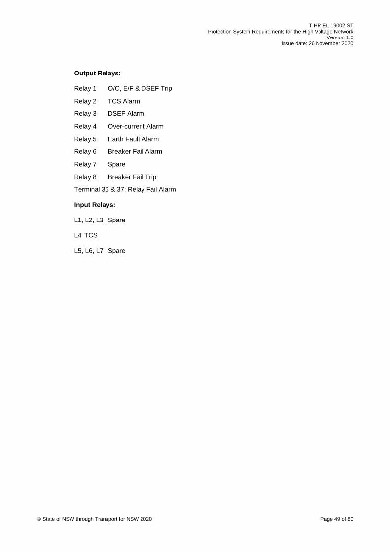
T HR EL 19002 ST Protection System Requirements for the High Voltage Network
Version 1.0 Issue date: 26 November 2020
© State of NSW through Transport for NSW 2020 Page 49 of 80
Output Relays:
Relay 1 O/C, E/F & DSEF Trip
Relay 2 TCS Alarm
Relay 3 DSEF Alarm
Relay 4 Over-current Alarm
Relay 5 Earth Fault Alarm
Relay 6 Breaker Fail Alarm
Relay 7 Spare
Relay 8 Breaker Fail Trip
Terminal 36 & 37: Relay Fail Alarm
Input Relays:
L1, L2, L3 Spare
L4 TCS
L5, L6, L7 Spare

T HR EL 19002 ST Protection System Requirements for the High Voltage Network
Version 1.0 Issue date: 26 November 2020
© State of NSW through Transport for NSW 2020 Page 50 of 80
D.3. Rectifier protection Rectifier Protection
MiCOM P14N Relay
Relay MMLG01 Incoming Supplies
Relay 1 contact 2 x 1 Trip +ve
Relay 1 contact 4 x 3 Over-current Trip
Relay 3 contact 6 x 5 Trip +ve
Relay 3 contact 8 x 7 Earth Fault Trip
Spare 10 x 9 Spare
Spare 12 x 11 Spare
Terminal 33 14 II 13 + 125 V dc aux supply
Terminal 34 16 x 15 - 125 V dc aux supply
Relay 8 contact 18 x 17 Trip +ve
Relay 8 contact 20 x 19 CB Fail trip
Ia 22 x 21 Ia
Ib 24 x 23 Ib
Ic 26 x 25 Ic
Io 28 x 27 Io
Output Relays:
Relay Healthy Relay watchdog
Relay Failed Spare
Relay 1 Over-current Trip
Relay 2 Spare
Relay 3 Earth Fault Trip (to MTM)
Relay 4 Spare
Relay 5 Earth Fault Trip to PLC if required
Relay 7 Spare
Relay 8 Breaker Fail Trip
Relay 9 - 12 Spare
Terminal 36 & 37: Relay Fail Alarm
Input Relays:
L1 to L8 Spare
L9 TCS
L10 & L11 Spare

T HR EL 19002 ST Protection System Requirements for the High Voltage Network
Version 1.0 Issue date: 26 November 2020
© State of NSW through Transport for NSW 2020 Page 51 of 80
Rectifier Protection
MiCOM P127 Relay
Relay MMLG01 Incoming Supplies
Relay 1 contact 2 x 1 Trip +ve
Relay 1 contact 4 x 3 Over-current Trip
Relay 3 contact 6 x 5 Trip +ve
Relay 3 contact 8 x 7 Earth Fault Trip
10 x 9 Spare
12 x 11 Spare
Terminal 33 14 II 13 + 125 V dc aux supply
Terminal 34 16 x 15 - 125 V dc aux supply
Relay 8 contact 18 x 17 Trip +ve
Relay 8 contact 20 x 19 CB Fail trip
Ia 22 x 21 Ia
Ib 24 x 23 Ib
Ic 26 x 25 Ic
Io 28 x 27 Io
Output Relays:
Relay 1 Not used (see Note 1)
Relay 2 TCS Alarm
Relay 3 Earth Fault Trip (to MTM)
Relay 4 Over-current and Earth Fault Alarm
Relay 5 Earth Fault Trip (to PLC)
Relay 6 Breaker Fail Alarm
Relay 7 Over-current Trip
Relay 8 Breaker Fail Trip
Terminal 36 & 37: Relay Fail Alarm
NOTE 1: The breaker fail function of this relay is initiated internally by Relay 1, hence
Relay 1 is programmed to be energised for either an OC or EF trip.
Input Relays:
L1, L2, L3 Spare
L4 TCS
L5 Timer initiate (from Rectifier MTM)

T HR EL 19002 ST Protection System Requirements for the High Voltage Network
Version 1.0 Issue date: 26 November 2020
© State of NSW through Transport for NSW 2020 Page 52 of 80
L6, L7 Spare
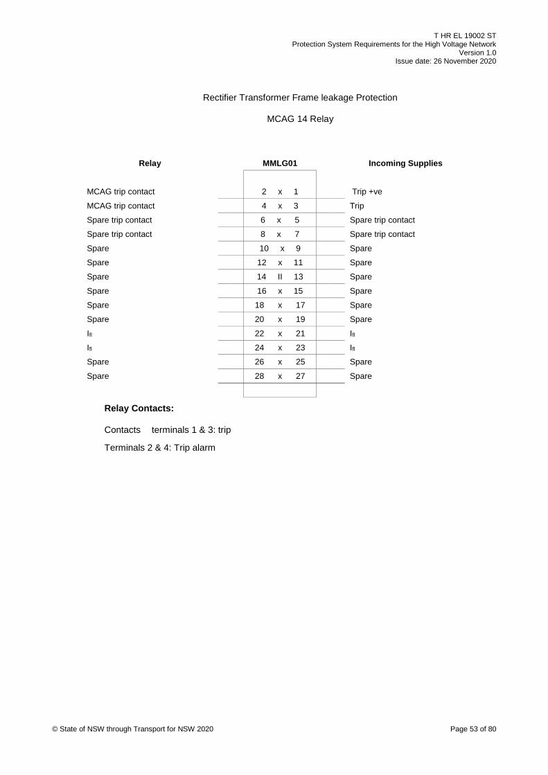
T HR EL 19002 ST Protection System Requirements for the High Voltage Network
Version 1.0 Issue date: 26 November 2020
© State of NSW through Transport for NSW 2020 Page 53 of 80
Rectifier Transformer Frame leakage Protection
MCAG 14 Relay
Relay MMLG01 Incoming Supplies
MCAG trip contact 2 x 1 Trip +ve
MCAG trip contact 4 x 3 Trip
Spare trip contact 6 x 5 Spare trip contact
Spare trip contact 8 x 7 Spare trip contact
Spare 10 x 9 Spare
Spare 12 x 11 Spare
Spare 14 II 13 Spare
Spare 16 x 15 Spare
Spare 18 x 17 Spare
Spare 20 x 19 Spare
Ifl 22 x 21 Ifl
Ifl 24 x 23 Ifl
Spare 26 x 25 Spare
Spare 28 x 27 Spare
Relay Contacts:
Contacts terminals 1 & 3: trip
Terminals 2 & 4: Trip alarm

T HR EL 19002 ST Protection System Requirements for the High Voltage Network
Version 1.0 Issue date: 26 November 2020
© State of NSW through Transport for NSW 2020 Page 54 of 80
D.4. System transformer protection HV/LV kV Transformer Differential Protection
MiCOM P632 Relay
TEST BLOCK 1
Relay MMLG01 Incoming Supplies
Tx Diff trip contact 2 x 1 MVAJ Trip +ve
Tx Diff trip contact 4 x 3 MVAJ Trip
Spare 6 x 5 Spare
Spare 8 x 7 Spare
Spare 10 x 9 Spare
Spare 12 x 11 Spare
Test Block 2 – Term. 13 14 II 13 + 125V dc Aux Supply
Test Block 2 – Term. 15 16 x 15 - 125V dc Aux Supply
HV CBFail contact 18 x 17 Trip +ve (HV panel)
HV CBFail contact 20 x 19 HV CBFail Trip
Ia (HV CT input) 22 x 21 Ia (HV CT)
Ib (HV CT input) 24 x 23 Ib (HV CT)
Ic (HV CT input) 26 x 25 Ic (HV CT)
Io (HV CT input) 28 x 27 Io (HV CT)

T HR EL 19002 ST Protection System Requirements for the High Voltage Network
Version 1.0 Issue date: 26 November 2020
© State of NSW through Transport for NSW 2020 Page 55 of 80
TEST BLOCK 2
Relay MMLG01 Incoming Supplies
AUX TRIP CONTACT (see Notes 2 & 4)
2 x 1 MVAJ Trip +ve
AUX TRIP CONTACT (where required)
4 x 3 MVAJ Trip
Spare 6 x 5 Spare
Spare 8 x 7 Spare
Spare 10 x 9 Spare
Spare 12 x 11 Spare
P632 Aux Supply input 14 II 13 Test Block 1 – Term. 14
P632 Aux Supply input 16 x 15 Test Block 1 – Term. 16
LV CBFail contact (where required)
18 x 17 Trip +ve (LV panel)
LV CBFail contact (where required)
20 x 19 LV CBFail Trip
Ia (LV CT input) 22 x 21 Ia (LV CT)
Ib (LV CT input) 24 x 23 Ib (LV CT)
Ic (LV CT input) 26 x 25 Ic (LV CT)
Io (LV CT input) 28 x 27 Io (LV CT)
OUTPUT RELAYS (P632):
K901 TX DIFFERENTIAL TRIP (Note 4) K902 RELAY WATCHDOG K903 HV CBFAIL BACKTRIP K904, K905, K906, K907, K908 Spare
K701 TX & TAP CHANGER AUX TRIP (where applicable, see Notes 2 & 4) K702 Spare K703 LV CBFAIL BACKTRIP (where required) K704 Spare K705 Spare K706 Spare K707 Spare K708 Spare
Note: All relay alarms except Watchdog by means of Serial Communications (DNP3.0)
OPTO INPUTS (P632) (where applicable, see Note 2):
U901 TAP CHANGER BUCHHOLZ OIL SURGE OPERATION U902 TAP CHANGER PRESSURE SWITCH U903 TAP CHANGER BUCHHOLZ GAS ALARM

T HR EL 19002 ST Protection System Requirements for the High Voltage Network
Version 1.0 Issue date: 26 November 2020
© State of NSW through Transport for NSW 2020 Page 56 of 80
U904 TAP CHANGER LOW OIL
U701 TX BUCHHOLZ OIL SURGE OPERATION U702 TCS U703 TX WINDING TEMPERATURE U704 TX BUCHHOLZ GAS OPERATION U705 TX LOW OIL OR TX OIL TEMPERATURE U706 TX PRESSURE SWITCH
Note 1: All alarms except Relay Watchdog are to be by means of serial
communications. In cases where serial communications are not achievable, an
amended Test Block & I/O Wiring Configuration will be attached to the Protection
Concept Design.
Note 2: Inputs allocation shown above is a typical list. Some Tx & Tap Changer
inputs may not be required depending on the type and model of the transformer
available on site. Where a different auxiliary operation required is not listed above,
please use next available spare P632 input and inform the Electrical Protection
Systems Engineer for relay setting.
Note 3: If Test Block 2 is not required, terminals 14 & 16 of Test Block 1 will be wired
into P632 Aux Supply Input.
Note 4: If Transformer Differential trips by means of the MTM, then transformer and
tap changer auxiliary trips are to be combined with transformer differential trip through
output relay K901.
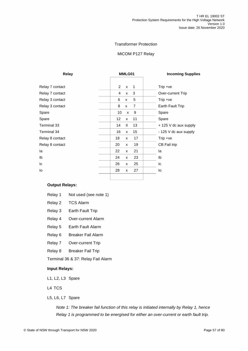
T HR EL 19002 ST Protection System Requirements for the High Voltage Network
Version 1.0 Issue date: 26 November 2020
© State of NSW through Transport for NSW 2020 Page 57 of 80
Transformer Protection
MiCOM P127 Relay
Relay MMLG01 Incoming Supplies
Relay 7 contact 2 x 1 Trip +ve
Relay 7 contact 4 x 3 Over-current Trip
Relay 3 contact 6 x 5 Trip +ve
Relay 3 contact 8 x 7 Earth Fault Trip
Spare 10 x 9 Spare
Spare 12 x 11 Spare
Terminal 33 14 II 13 + 125 V dc aux supply
Terminal 34 16 x 15 - 125 V dc aux supply
Relay 8 contact 18 x 17 Trip +ve
Relay 8 contact 20 x 19 CB Fail trip
Ia 22 x 21 Ia
Ib 24 x 23 Ib
Ic 26 x 25 Ic
Io 28 x 27 Io
Output Relays:
Relay 1 Not used (see note 1)
Relay 2 TCS Alarm
Relay 3 Earth Fault Trip
Relay 4 Over-current Alarm
Relay 5 Earth Fault Alarm
Relay 6 Breaker Fail Alarm
Relay 7 Over-current Trip
Relay 8 Breaker Fail Trip
Terminal 36 & 37: Relay Fail Alarm
Input Relays:
L1, L2, L3 Spare
L4 TCS
L5, L6, L7 Spare
Note 1: The breaker fail function of this relay is initiated internally by Relay 1, hence
Relay 1 is programmed to be energised for either an over-current or earth fault trip.
T HR EL 19002 ST Protection System Requirements for the High Voltage Network
Version 1.0 Issue date: 26 November 2020
© State of NSW through Transport for NSW 2020 Page 58 of 80
However it is not connected externally as an over-current trip is require to energise an
MTA relay and the earth fault trip is required to energise an MTM relay.

T HR EL 19002 ST Protection System Requirements for the High Voltage Network
Version 1.0 Issue date: 26 November 2020
© State of NSW through Transport for NSW 2020 Page 59 of 80
Transformer Protection - Over-current & Neutral Leakage (11kV side)
MiCOM P127 Relay
Relay MMLG01 Incoming Supplies
Relay 7 contact 2 x 1 Trip +ve
Relay 7 contact 4 x 3 Over-current Trip
Relay 3 contact 6 x 5 Trip +ve
Relay 3 contact 8 x 7 Neutral Leakage Trip
In 10 x 9 In
In 12 x 11 In
Terminal 33 14 II 13 + 125 V dc aux supply
Terminal 34 16 x 15 - 125 V dc aux supply
Relay 8 contact 18 x 17 Trip +ve
Relay 8 contact 20 x 19 CB Fail trip
Ia 22 x 21 Ia
Ib 24 x 23 Ib
Ic 26 x 25 Ic
Io 28 x 27 Io
Output Relays:
Relay 1 Spare
Relay 2 TCS Alarm
Relay 3 Neutral Leakage Trip (to MTA relay)
Relay 4 Over-current Alarm
Relay 5 Neutral Leakage Alarm
Relay 6 Breaker Fail Alarm
Relay 7 Over-current Trip
Relay 8 Breaker Fail Trip
Terminal 36 & 37: Relay Fail Alarm
Input Relays:
L1, L2, L3 Spare
L4 TCS
L5, L6, L7 Spare
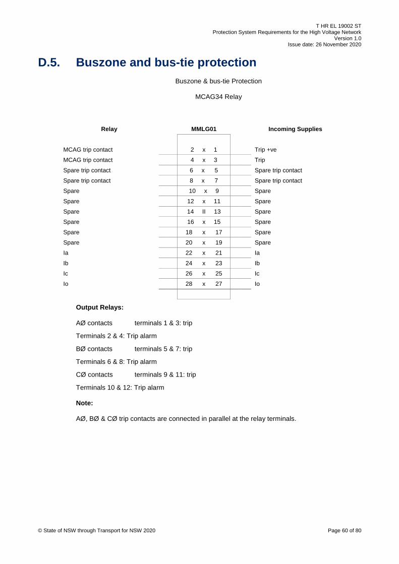
T HR EL 19002 ST Protection System Requirements for the High Voltage Network
Version 1.0 Issue date: 26 November 2020
© State of NSW through Transport for NSW 2020 Page 60 of 80
D.5. Buszone and bus-tie protection Buszone & bus-tie Protection
MCAG34 Relay
Relay MMLG01 Incoming Supplies
MCAG trip contact 2 x 1 Trip +ve
MCAG trip contact 4 x 3 Trip
Spare trip contact 6 x 5 Spare trip contact
Spare trip contact 8 x 7 Spare trip contact
Spare 10 x 9 Spare
Spare 12 x 11 Spare
Spare 14 II 13 Spare
Spare 16 x 15 Spare
Spare 18 x 17 Spare
Spare 20 x 19 Spare
Ia 22 x 21 Ia
Ib 24 x 23 Ib
Ic 26 x 25 Ic
Io 28 x 27 Io
Output Relays:
AØ contacts terminals 1 & 3: trip
Terminals 2 & 4: Trip alarm
BØ contacts terminals 5 & 7: trip
Terminals 6 & 8: Trip alarm
CØ contacts terminals 9 & 11: trip
Terminals 10 & 12: Trip alarm
Note:
AØ, BØ & CØ trip contacts are connected in parallel at the relay terminals.
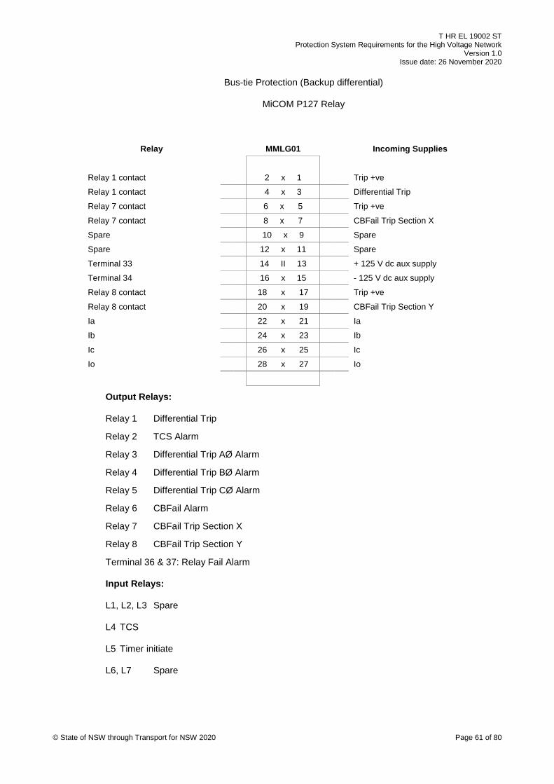
T HR EL 19002 ST Protection System Requirements for the High Voltage Network
Version 1.0 Issue date: 26 November 2020
© State of NSW through Transport for NSW 2020 Page 61 of 80
Bus-tie Protection (Backup differential)
MiCOM P127 Relay
Relay MMLG01 Incoming Supplies
Relay 1 contact 2 x 1 Trip +ve
Relay 1 contact 4 x 3 Differential Trip
Relay 7 contact 6 x 5 Trip +ve
Relay 7 contact 8 x 7 CBFail Trip Section X
Spare 10 x 9 Spare
Spare 12 x 11 Spare
Terminal 33 14 II 13 + 125 V dc aux supply
Terminal 34 16 x 15 - 125 V dc aux supply
Relay 8 contact 18 x 17 Trip +ve
Relay 8 contact 20 x 19 CBFail Trip Section Y
Ia 22 x 21 Ia
Ib 24 x 23 Ib
Ic 26 x 25 Ic
Io 28 x 27 Io
Output Relays:
Relay 1 Differential Trip
Relay 2 TCS Alarm
Relay 3 Differential Trip AØ Alarm
Relay 4 Differential Trip BØ Alarm
Relay 5 Differential Trip CØ Alarm
Relay 6 CBFail Alarm
Relay 7 CBFail Trip Section X
Relay 8 CBFail Trip Section Y
Terminal 36 & 37: Relay Fail Alarm
Input Relays:
L1, L2, L3 Spare
L4 TCS
L5 Timer initiate
L6, L7 Spare

T HR EL 19002 ST Protection System Requirements for the High Voltage Network
Version 1.0 Issue date: 26 November 2020
© State of NSW through Transport for NSW 2020 Page 62 of 80
D.6. Harmonic filter protection Harmonic Filter Protection: Double-Star Point Unbalance Protection, Repetitive Peak
Overvoltage, Thermal Over-current
RLC04 RELAY 1
Relay 1 MMLG01 Incoming Supplies
Trip contact (Term. 10) 2 x 1 Trip +ve
Trip contact (Term. 12) 4 x 3 RPOV, ThOC & DSU trip
Spare 6 x 5 Spare
Spare 8 x 7 Spare
CT input (Term. 28) 10 x 9 Icap (double star unbalance CT)
CT input (Term. 27) 12 x 11 Icap (double star unbalance CT)
Aux input (Term. 5) 14 II 13 + 125 V dc aux supply
Aux input (Term. 7) 16 x 15 - 125 V dc aux supply
CBFail trip contact (Term. 17) 18 x 17 Trip +ve
CBFail trip contact (Term. 19) 20 x 19 CBFail trip
CT input 1 (Term. 22) 22 x 21 TBK 2 (Term. 11)
CT input 2 (Term 24) 24 x 23 Ib (Line CT)
CT input 3 (Term 26) 26 x 25 Ic (Line CT)
CT inputs 4 (Term. 21,23, 25) 28 x 27 Io (Line CT)
Output Relays:
Relay K1 Repetitive Peak Overvoltage, Thermal Over-current & Double
Star Unbalance Trip
Relay K2 Spare
Relay K3 Spare
Relay K4 Spare
Relay K5 Breaker Fail Trip
Relay K6 RLC04 Relay 1 Fail Alarm
Note: All alarms except the watchdog are to be serial linked (Modbus).
Input Relays:
Input 1 Spare

T HR EL 19002 ST Protection System Requirements for the High Voltage Network
Version 1.0 Issue date: 26 November 2020
© State of NSW through Transport for NSW 2020 Page 63 of 80
Harmonic Filter Protection: H-Bridge Unbalance Protection
RLC04 Relay 2
Relay 2 MMLG01 Incoming Supplies
Trip contact (Term. 10) 2 x 1 Trip +ve
Trip contact (Term. 12) 4 x 3 HBU trip
CT input (Term. 23) 6 x 5 Ia- (H-Bridge A phase CT)
CT input (Term. 25) 8 x 7 Ib- (H-Bridge B phase CT)
CT input (Term. 27) 10 x 9 Ic- (H-Bridge C phase CT)
CT input (Term. 21) 12 x 11 TBK 1 (Term. 21)
Aux input (Term. 5) 14 II 13 + 125 V dc aux supply
Aux input (Term. 7) 16 x 15 - 125 V dc aux supply
CBFail contact (Term. 17) 18 x 17 Trip +ve
CBFail contact (Term. 19) 20 x 19 CBFail timer initiate to P127 (27/51/HF) relay
CT input 1 (Term. 24) 22 x 21 Ia+ (H-Bridge A phase CT)
CT input 2 (Term. 26) 24 x 23 Ib+ (H-Bridge B phase CT)
CT input 3 (Term. 28) 26 x 25 Ic+ (H-Bridge C phase CT)
CT input 4 (Term. 22) 28 x 27 Ia+ (11 kV A phase line CT)
Output Relays:
Relay K1 H-BRIDGE Unbalance Trip
Relay K2 Spare
Relay K3 Spare
Relay K4 Spare
Relay K5 Trip – Breaker Fail Timer Initiate to P127 (27/51/HF) Relay, Input L5
Relay K6 RLC04 Relay 2 Fail Alarm
Note: All alarms except the watchdog are to be serial linked (Modbus).
Input Relays:
Input 1 Spare

T HR EL 19002 ST Protection System Requirements for the High Voltage Network
Version 1.0 Issue date: 26 November 2020
© State of NSW through Transport for NSW 2020 Page 64 of 80
Harmonic Filter Protection: Over-current & Earth Fault Protection and Undervoltage Protection
P127 Relay
Relay MMLG01 Incoming Supplies
Relay 1 contact 2 x 1 Trip +ve
Relay 1 contact 4 x 3 Over-current and earth fault and phase undervoltage trip
VT input 1 (Term. 69) 6 x 5 Va
VT input 2 (Term. 71) 8 x 7 Vb
VT input 3 (Term. 73) 10 x 9 Vc
VT input 4 (Term. 70, 72, 74) 12 x 11 Vo
Terminal 33 14 II 13 + 125 V dc aux supply
Terminal 34 16 x 15 - 125 V dc aux supply
Relay 8 contact 18 x 17 Trip +ve
Relay 8 contact 20 x 19 Breaker fail trip
Ia 22 x 21 Ia
Ib 24 x 23 Ib
Ic 26 x 25 Ic
Io 28 x 27 Io
Output Relays:
Relay 1 Over-current & Earth Fault and Phase Undervoltage Trip
Relay 2 – Relay 7 Spare
Relay 8 Breaker Fail Trip
Terminal 36 & 37: Relay Fail Alarm
Note: All alarms except the watchdog are to be serial linked (DNP3.0)
Input Relays:
Input L1 Spare
Input L2 Spare
Input L3 Spare
Input L4 TCS
Input L5 Timer initiate from RLC04[2]
Input L6 Spare
Input L7 Spare

T HR EL 19002 ST Protection System Requirements for the High Voltage Network
Version 1.0 Issue date: 26 November 2020
© State of NSW through Transport for NSW 2020 Page 65 of 80
Appendix E Auto re-close on high voltage feeders
This appendix provides the re-closure guideline for HV feeders on the RailCorp HV distribution
network. The operator and maintainer can develop and vary re-closure policy from this appendix
based on a risk analysis.
In general, HV feeders have one auto re-close in five seconds by SCADA (that is, the master
station initiates the auto re-close if all the requirements are met).
This policy applies to the following:
• 11 kV, 33 kV and 66 kV feeders that are entirely aerial lines
• a feeder that is partially cable and partially aerial line is treated as an aerial line
• where an aerial feeder is located outside the rail corridor, the auto re-close shall be based
on a risk assessment
Supply point feeders, feeders that are entirely cable and feeders with SEF protection shall not
have auto re-close implemented.
During periods of total fire ban, the auto re-close is inhibited on HV feeders that traverse areas
that are considered to be a bush fire risk in accordance with SP D 79036 - Sydney Trains
Electricity Distribution Network Bushfire Risk Management Plan. This is a master station
function initiated by the electrical system operator. Auto re-close is also automatically inhibited
for 10 minutes after a close control is initiated by the electrical system operator.
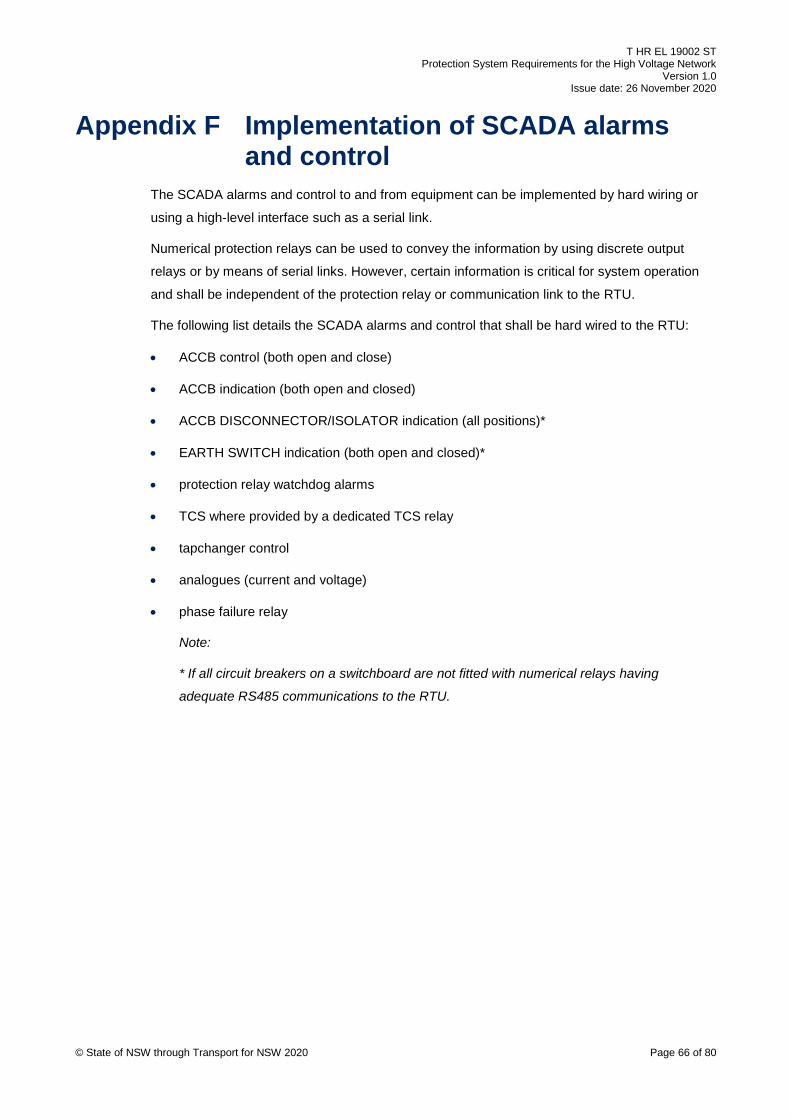
T HR EL 19002 ST Protection System Requirements for the High Voltage Network
Version 1.0 Issue date: 26 November 2020
© State of NSW through Transport for NSW 2020 Page 66 of 80
Appendix F Implementation of SCADA alarms and control
The SCADA alarms and control to and from equipment can be implemented by hard wiring or
using a high-level interface such as a serial link.
Numerical protection relays can be used to convey the information by using discrete output
relays or by means of serial links. However, certain information is critical for system operation
and shall be independent of the protection relay or communication link to the RTU.
The following list details the SCADA alarms and control that shall be hard wired to the RTU:
• ACCB control (both open and close)
• ACCB indication (both open and closed)
• ACCB DISCONNECTOR/ISOLATOR indication (all positions)*
• EARTH SWITCH indication (both open and closed)*
• protection relay watchdog alarms
• TCS where provided by a dedicated TCS relay
• tapchanger control
• analogues (current and voltage)
• phase failure relay
Note:
* If all circuit breakers on a switchboard are not fitted with numerical relays having
adequate RS485 communications to the RTU.

T HR EL 19002 ST Protection System Requirements for the High Voltage Network
Version 1.0 Issue date: 26 November 2020
© State of NSW through Transport for NSW 2020 Page 67 of 80
Appendix G Typical ACCB auxiliary supply arrangement
Figure 1 and Figure 2 provide detail on the typical arrangement of dc auxiliary supply to HV
ACCBs.
Both Figure 1 and Figure 2 show the positive fuse only. The fuse in the negative has not been
shown for clarity. The arrangement is also applicable when circuit breakers are used instead of
fuses.
Where two batteries are present in a substation the protection concept will detail the exact
arrangement for the dc auxiliary supply.
In two battery locations, where a HV panel has two 125 V dc submains, the submains are
required to be installed in separate diverse routes.
Figure 1 – Typical arrangement for dc auxiliary supply to HV ACCB for a substation with one battery.
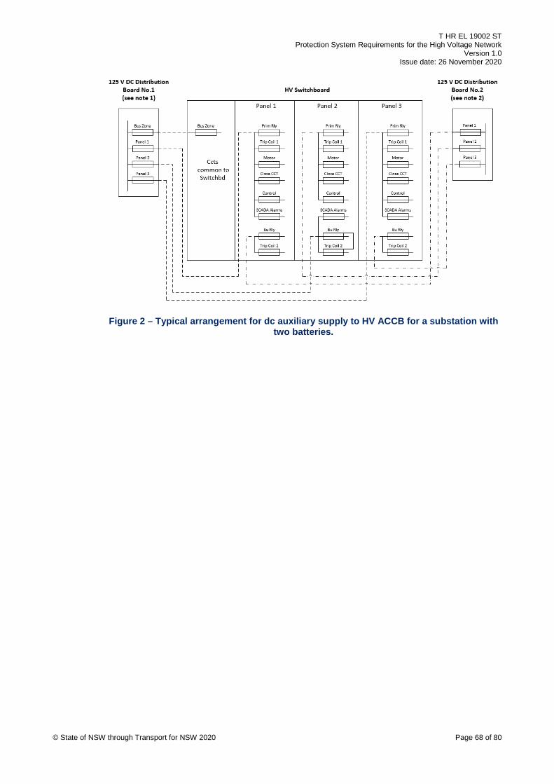
T HR EL 19002 ST Protection System Requirements for the High Voltage Network
Version 1.0 Issue date: 26 November 2020
© State of NSW through Transport for NSW 2020 Page 68 of 80
Figure 2 – Typical arrangement for dc auxiliary supply to HV ACCB for a substation with two batteries.

T HR EL 19002 ST Protection System Requirements for the High Voltage Network
Version 1.0 Issue date: 26 November 2020
© State of NSW through Transport for NSW 2020 Page 69 of 80
Appendix H Protection labelling guidelines The rules in Section H.1 to Section H.5 apply to the labelling of protection relays and associated
auxiliary relays.
H.1. Location of labels Labels should be located directly above the relay. If this is not possible, then they should be
located directly below the relay.
H.2. Colour of labels All labels for protection relays shall have black writing on a yellow background.
All auxiliary relays (such as multi-trip relays) shall have black writing on a white background.
H.3. Format The following are the formatting requirements for labels:
• To keep the length of labels to a minimum, abbreviations shall be used for the protection
functions. The valid abbreviations are detailed in Table 6.
• All labels should be in CAPITALS (except for abbreviations such as ‘Tx’ and ‘kV’).
• The description of equipment shall be consistent with terminology as used in the ac
operating diagrams. This is summarised below:
o FEEDERS: ‘Feeder ID’
Where ‘Feeder ID’ is the unique three digit identification assigned to each HV feeder.
o TRANSFORMERS: ‘Unit ID’ + ‘voltage ratio’ + ‘Tx’
Where ‘Unit ID’ is the identification given where there are multiple transformers (such
as No.1, No.2, and so on) ‘voltage ratio’ is the voltage ratio of the transformer usually
expressed in kV (for example, 33/11kV, 66/33kV).
o RECTIFERS: ‘Unit ID’ + ‘RECTIFIER’
Where ‘Unit ID’ is the identification given where there are multiple rectifiers (such as
No.1, No.2, and so on).

T HR EL 19002 ST Protection System Requirements for the High Voltage Network
Version 1.0 Issue date: 26 November 2020
© State of NSW through Transport for NSW 2020 Page 70 of 80
H.4. Content FIRST LINE OF LABEL:
The following sequence should be used to construct a label:
a. equipment being protected or monitored or both
for example, No.1 RECTIFIER, BUS ZONE, 792, No.2 33/11kV Tx
b. type of protection
for example, DOC & DE RELAY, LINE DIFF, CURRENT CHECK, AØ DOC RELAY, AØ
OC RELAY, FL RELAY, Tx OC RELAY, Tx DIFF RELAY
c. make of relay in brackets
for example (P543), (P521), (P127), (MCAG34), (P632)
d. pointer to relay (if needed)
for example, ↑, ↓
H.5. Examples of labels The following are examples of labels:
• 798 DOC & DE RELAY (P127)
• 798 PW RELAY (P521)
• ↑ No.1 RECT IOC & IE RELAY (MCAG33)
• No.1 RECT IOC & IE BACKUP RELAY (P127)
• TRIP CCT 1 TCS RELAY (1TM10)
• No.1 33/11kV TxDIFF RELAY (P632)
• No.1 33/11kV Tx OC & E RELAY (P127)
• 1-2 BZT RELAY (MCAG34)
• ↓1-2 BZT MTM RELAY (MVAJ13)
• No.1 33/11kV Tx MTA RELAY (MVAJ11)
• No.1 SECTION BZ MTM RELAY (MVAJ13)
• 877 ENERGY METER (Mk6E)
• HF OC&E UV RELAY

T HR EL 19002 ST Protection System Requirements for the High Voltage Network
Version 1.0 Issue date: 26 November 2020
© State of NSW through Transport for NSW 2020 Page 71 of 80
Table 6 - Protection function abbreviation
Protection function Abbreviation
Arc Detection AD
Buchholz B
Breaker Fail BF
Blocking Relay BRly
Backup BU
Buszone BZ
Buszone Tie BZT
Directional Earth Fault DE
Directional Instantaneous Over-current DIOC
Directional Over-current DOC
Earth Fault E
DCCB Frame Leakage FLDC
AC Frame Leakage FL
Rectifier Frame Leakage FLR
Instantaneous Earth Leakage IE
Intelligent Gas Information System IGIS
Intelligent Light Information System ILIS
Instantaneous Over-current IOC
Intertrip IT
Instantaneous & Time Delay Over-current ITOC
Line Differential LD
Multi Trip Relay – Automatic Reset MTA
Multi Trip Relay – Manual Reset (Hand) MTM
Neutral Leakage NL
Over-current OC
Low Oil LO
Over-current & Residual Earth Fault Inverse Time ORET
Pressure Switch PS
Pilot Wire PW
Dc Reverse Current RC
Transformer Differential TxDIFF
Transformer Winding Temperature WT
Trip Circuit Supervision TCS
Trip Supply Supervision TSS
Overvoltage OV
Undervoltage UV

T HR EL 19002 ST Protection System Requirements for the High Voltage Network
Version 1.0 Issue date: 26 November 2020
© State of NSW through Transport for NSW 2020 Page 72 of 80
Protection function Abbreviation
Sensitive Earth Fault SEF

T HR EL 19002 ST Protection System Requirements for the High Voltage Network
Version 1.0 Issue date: 26 November 2020
© State of NSW through Transport for NSW 2020 Page 73 of 80
Appendix I Standard current transformer configurations
Figure 3, Figure 4 and Figure 5 are provided to illustrate the standard CT polarity configuration
for protection schemes in the RailCorp HV distribution network.
TRIP DIRECTION
B PHASE
A PHASE
C PHASE
SUBSTATIONBUSBARS
MICOMP127RELAY
45
46
47
48
53
54
55
56
41
42
43
44
49
50
51
52
1 A
CT
5 A
CT
TEST BLOCK
21 23 25 27
22 24 26 28
P1 P2
S1
S1
S1
S2
S2
S2
Figure 3 – CT configuration for directional over-current protection
SUBSTATION BUSBARS
1 A
CT
5 A
CT
B PHASE
A PHASE
C PHASE
MICOMP127RELAY
45
46
47
48
53
54
55
56
41
42
43
44
49
50
51
52
TEST BLOCK
21 23 25 27
22 24 26 28
P1 P2
1 A
CT
5 A
CT
MICOMP124RELAY
45
46
47
48
53
54
55
56
41
42
43
44
49
50
51
52
TEST BLOCK
21 23 25 27
22 24 26 28
P1 P2
TRIP DIRECTION
S2
S2
S2
S2
S2
S2
S1
S1
S1
S1
S1
S1
Figure 4 – CT configuration for rectifier protection
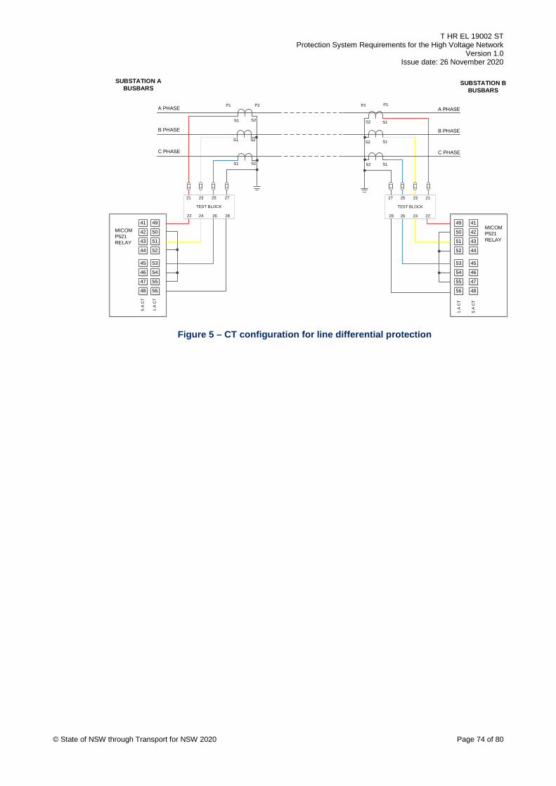
T HR EL 19002 ST Protection System Requirements for the High Voltage Network
Version 1.0 Issue date: 26 November 2020
© State of NSW through Transport for NSW 2020 Page 74 of 80
SUBSTATION ABUSBARS
1 A
CT
5 A
CT
B PHASE
A PHASE
C PHASE
MICOMP521RELAY
45
46
47
48
53
54
55
56
41
42
43
44
49
50
51
52
TEST BLOCK
21 23 25 27
22 24 26 28
P1 P2
SUBSTATION BBUSBARS
1 A
CT
5 A
CT
B PHASE
A PHASE
C PHASE
MICOMP521RELAY
45
46
47
48
53
54
55
56
41
42
43
44
49
50
51
52
TEST BLOCK
27 25 23 21
28 26 24 22
P1P2
S2
S2S2
S2
S2 S2
S1
S1
S1
S1
S1
S1
Figure 5 – CT configuration for line differential protection

T HR EL 19002 ST Protection System Requirements for the High Voltage Network
Version 1.0 Issue date: 26 November 2020
© State of NSW through Transport for NSW 2020 Page 75 of 80
Appendix J Metering requirements for bulk supply points
The metering requirements in Section J.1 to Section J.6 are applicable to RailCorp substations.
These requirements are correct at the time of publication of this standard and should be
confirmed with the relevant electricity distributor. The specified rated burden should also be
confirmed for suitability, particularly for substations with outdoor yards.
Check metering shall have identical CTs, VTs and energy meter as prescribed in Section J.1 to
Section J.6.
The requirements are based on the following documents:
• Ausgrid Network Standard, ES3 Metering Installation Requirements Part A, Document
NW000-S0141, July 2018
• Endeavour Energy Metering Design Instruction, High Voltage Measurement Current and
Voltage Transformers, Document No: MET 0002 (amendment 0)
• TransGrid, Secondary Systems Design Standard
J.1. Voltage transformers Where the VT is part of an indoor switchboard then a dedicated metering VT is required and
should be located on the associated feeder panel. The VT winding requirements are as follows:
• Indoor switchgear, dedicated winding required (1 per phase), class 0.5 and 50 VA for
Ausgrid, class 0.2 and 100 VA for Endeavour Energy, form factor of 1.9/30 s. Associated
LV ACCB installed on the output with auxiliary contact of ACCB connected to SCADA.
• Outdoor switchgear dedicated winding required (1 per phase), class 0.2 and 50 VA for
Ausgrid, class 0.2 and 100 VA for Endeavour Energy, form factor of 1.9/30 s. Associated
LV ACCB installed on the output with auxiliary contact of ACCB connected to SCADA.
• Warning label required adjacent to VT isolating handle (for example, ‘WARNING - VT
SUPPLIES 7XX REVENUE METERING ’).
J.2. Current transformers A dedicated set of metering class CTs with following parameters shall be provided:
• Ratio: identical to protection CTs on same feeder
• Designation: 15VA CLASS 0.5S
• Designation: 15VA CLASS 0.2 (outdoor CT for Endeavour Energy)

T HR EL 19002 ST Protection System Requirements for the High Voltage Network
Version 1.0 Issue date: 26 November 2020
© State of NSW through Transport for NSW 2020 Page 76 of 80
• Thermal limit current = 2.0 A (for 1A secondary CT)
• Rated short-time current and associated time to match the switchboard rating
The CTs are required to be positioned adjacent to the metering CTs used for TfNSW check
metering.
Additional secondary wiring and associated CT links are required for connection to the new
CTs.
J.3. Current transformer and voltage transformer test results The manufacturers’ test reports for the VTs and CTs are required to be submitted to TfNSW and
also stored in the operator and maintainer’s asset management system.
J.4. Secondary wiring from HV switchboard to meter panel The following are the requirements for the installation of the secondary wiring from the CT and
VT:
• The CT and VT secondary wiring is required to be run in separate conduits to the meter
panel.
• The CT secondary wiring shall be a multi-core cable, minimum size of 2.5 mm2.
• The VT secondary wiring shall be a multi-core cable, minimum size of 2.5 mm2 for Ausgrid
and 4 mm2 for Endeavour Energy.
J.5. 240 V ac supply to metering panel A dedicated 240 V ac supply from the substation 415 V distribution board is required to be run
in a dedicated conduit to the metering panel.
The 415 V distribution board is to have appropriate identification label and additional label ‘DO
NOT TURN OFF’ or similar adjacent to the low voltage circuit breaker.
J.6. Metering panel The proposed location of the metering panel has to be approved by the operator and maintainer
prior to installation. The metering panel should be located on the external wall of the substation.
The metering panel shall not be located outside the substation boundary.
The metering panel (including equipment) should be purchased directly from the electricity
distributor or their recommended supplier where available.

T HR EL 19002 ST Protection System Requirements for the High Voltage Network
Version 1.0 Issue date: 26 November 2020
© State of NSW through Transport for NSW 2020 Page 77 of 80
Appendix K Wire identification for current transformer, voltage transformer, general protection
Wire identification shall generally be in accordance with AS 2067 Substations and high voltage
installations exceeding 1 kV a.c. The detailed implementation shall be in accordance with Table
7.
Refer to T HR EL 11004 ST Electrical SCADA Interface Requirements and T HR EL 11001 PR
Design Technical Reviews for Electrical SCADA Equipment for details on SCADA cabling and
wiring including communication wiring.
Table 7 – Wire identification
Letter Circuit function Wire numbers
A Current transformers for primary protection, excluding over-current
10-29 Red phase 30-49 White phase 50-69 Blue phase 70-89 Residual circuits and neutral current transformers 90 Earth wires directly connected to the earth bar 91-99 test windings, normally inoperative
B Current transformer for busbar protection
10-29 Red phase 30-49 White phase 50-69 Blue phase 70-89 Residual circuits and neutral current transformers 90 Earth wires directly connected to the earth bar 91-99 test windings, normally inoperative
C Current transformers for over-current protection (including combined earth-fault and instruments, H Bridge & double star unbalance)
10-29 Red phase 30-49 White phase 50-69 Blue phase 70-89 Residual circuits and neutral current transformers 90 Earth wires directly connected to the earth bar 91-99 test windings, normally inoperative

T HR EL 19002 ST Protection System Requirements for the High Voltage Network
Version 1.0 Issue date: 26 November 2020
© State of NSW through Transport for NSW 2020 Page 78 of 80
Letter Circuit function Wire numbers
D Current transformers for instruments, metering voltage control
10-29 Red phase 30-49 White phase 50-69 Blue phase 70-89 Residual circuits and neutral current transformers 90 Earth wires directly connected to the earth bar 91-99 test windings, normally inoperative
E Reference voltage of instruments, metering and protection
10-29 Red phase 30-49 White phase 50-69 Blue phase 70-89 Residual circuits and neutral current transformers 90 Earth wires directly connected to the earth bar 91-99 test windings, normally inoperative
F Reference voltage for voltage control
10-29 Red phase 30-49 White phase 50-69 Blue phase 70-89 Residual circuits and neutral current transformers 90 Earth wires directly connected to the earth bar 91-99 test windings, normally inoperative
K Closing and tripping control circuits Any number from 1 upwards
L Alarms and indications initiated by auxiliary switches and relay contact, excluding those for remote selective control and for general indication equipment
Any number from 1 upwards
T Pilot conductors (including directly associated connections) between panels, independent of the distance between them, for pilot-wire protection, for intertripping or for both
Any number from 1 upwards
X Alarms and indications to and from general indication and remote selective control equipment. This includes serial communication wiring from protection relays.
Any number from 1 upwards
Note:
If more numbers are required, add multiples of one hundred. For example, 10-29 may
be extended to 110-129, 210-229.

T HR EL 19002 ST Protection System Requirements for the High Voltage Network
Version 1.0 Issue date: 26 November 2020
© State of NSW through Transport for NSW 2020 Page 79 of 80
Appendix L Harmonic filter connection diagram Figure 6 depicts the harmonic filter connection.
Figure 6 - Harmonic filter connection

T HR EL 19002 ST Protection System Requirements for the High Voltage Network
Version 1.0 Issue date: 26 November 2020
© State of NSW through Transport for NSW 2020 Page 80 of 80
Appendix M Requirements for copper pilot wire schemes
This appendix provides the requirements for copper pilot wire schemes. The RailCorp HV
distribution network at the time of publication of this standard still has numerous copper based
pilot wire schemes in service.
The following applies:
• A minimum of 15 kV isolation shall be provided to avoid transfer of voltages across the
pilots. This shall be achieved by using an isolation transformer for intertripping by means of
an intertrip relay at both ends of the scheme.
• If the breaker fail function is associated with a feeder that does not have a dedicated
ACCB, then it is acceptable to implement an intertrip by destabilising the pilot wire line
differential schemes of feeders that are a possible source of fault current. When
destabilising the pilot wireline differential schemes this shall be implemented at the pilot
wire line differential relay.
• If the pilot circuit is not run by means of a dedicated pilot cable, then an instantaneous
over-current and earth fault check relay shall be provided in series with the trip from the
pilot wire relay to prevent nuisance tripping of the feeder.
• All pilot wire schemes shall include pilot circuit supervision. This may be implemented
either as a function of the pilot wire relay or using dedicated pilot circuit supervision
equipment.
• Pilot cables shall comply with AS/NZS 2373 Electric cables - Twisted pair for control and
protection circuits.


![[1] · 4.ΚΟΡΑΚΗΣ ΞΕΝΟΦΩΝ 5.ΤΣΙΛΙΚΑ ΔΗΜΗΤΡΑ ΙΩΑΝΝΟΥ ΜΕΤΑΞΑ 25 19002 ΠΑΙΑΝΙΑ photoharmony_gantzios@yahoo.gr 5. ΚΑΜΖΕΛΑΣ ΑΧΙΛΛΕΑΣ-](https://static.fdocuments.net/doc/165x107/5e05ffa7aa56260a74779945/1-4-5-oe-.jpg)


