t GuideS0For - ERIC · ce, 'ye!", Classroom Course 8-8. CONSTRUCTION MECHANiC, ENGINE TUNE-UP 11...
99
ED Z23' 965 TITLE -INSTITUTION 4m6PONS AGENCY, PUB DATL NOTE .PUB TYPE EDRS PRICE DESCRIPTORS. MOCUMENT RESUME CE 034 545 Construction MeChanic, Engine Tune-Up II (Diesel), 8-8. Military Curriculum Materials for Vocational an Technical Education. Naval Construction Training Centq, Port Hueneme,' Calif.; Ohio State Univ., Columbus. Nafional Center. for Research in Vocational Eduction. Office of Educatibn (DHEW), Washington, D.C. : 78 154p.; For related documents, see CE 03f 542-544. Guides - Classrooi Use - Materials (Foritiearner) t (051) -- Guides Classroom Use GuideS0For Teachers) (052) ,MF01/PC07 PlusPostage. Audibvisual Aids; *Auto Mechanics; Course CoiAent; *Diesel Engines; Educational Resources; *Engines; Hand Tools; Learning,Activities;. Lesson Plans; *Mechanics (Process); *Motor Vehicles; Postsecondary Educafion; Power Technology; Secondary Education; Technical Education; *Units of Study; Vocational Education - IDENTIFIERS Automotive Fuel Systems; *Automotive Tune Up; Militarz Curriculum Projedt ABSTRACT . This course, adapted from military curriculum materials for vOcational and technical education, teaches students tO restore diesel imgine performance to the manufactueer's specifications hrough troubleshooting and inalyzing diesel engine' fuel systems and to make minor and major ad3ustments to these components that dkrectly affect engine' performance. Students will learn to use,appropriati hand tools, special toolop, and shop equipment to test, adjust, and replace fuel sygtem components that fail td meet the manufacturer's specifications. The course consists of two units with one lesson in each, making-up 56 hours of classroom , and shop instruction. Unit 1 covers introductory,material and.safety precautions, while unit 2 focuses on engine tune-up. The course 'consists_of a single document containing both student and teacher materials. Instructor materials provided are an introduction to the course; an outline of training objectives; lists of texts, references, tools, equipment, training devices, and training aids ajuipment; a master schedule; and lesson plans. The lesson plans contain an outline of instruction and activities,for teachers and Atudents. Student materials provided include threé job sheets _and one information sheet. (IC) *********************************************************************** Reproductiyns supplied by EDRS are the best that can be made from the original document. *****************************************************.*******************
Transcript of t GuideS0For - ERIC · ce, 'ye!", Classroom Course 8-8. CONSTRUCTION MECHANiC, ENGINE TUNE-UP 11...

ED Z23' 965
TITLE
-INSTITUTION
4m6PONS AGENCY,PUB DATLNOTE.PUB TYPE
EDRS PRICEDESCRIPTORS.
MOCUMENT RESUME
CE 034 545
Construction MeChanic, Engine Tune-Up II (Diesel),8-8. Military Curriculum Materials for Vocational anTechnical Education.Naval Construction Training Centq, Port Hueneme,'Calif.; Ohio State Univ., Columbus. Nafional Center.for Research in Vocational Eduction.Office of Educatibn (DHEW), Washington, D.C. :
78154p.; For related documents, see CE 03f 542-544.Guides - Classrooi Use - Materials (Foritiearner) t
(051) -- Guides Classroom Use GuideS0ForTeachers) (052)
,MF01/PC07 PlusPostage.Audibvisual Aids; *Auto Mechanics; Course CoiAent;*Diesel Engines; Educational Resources; *Engines;Hand Tools; Learning,Activities;. Lesson Plans;*Mechanics (Process); *Motor Vehicles; PostsecondaryEducafion; Power Technology; Secondary Education;Technical Education; *Units of Study; VocationalEducation -
IDENTIFIERS Automotive Fuel Systems; *Automotive Tune Up;Militarz Curriculum Projedt
ABSTRACT. This course, adapted from military curriculum
materials for vOcational and technical education, teaches students tOrestore diesel imgine performance to the manufactueer'sspecifications hrough troubleshooting and inalyzing diesel engine'fuel systems and to make minor and major ad3ustments to thesecomponents that dkrectly affect engine' performance. Students willlearn to use,appropriati hand tools, special toolop, and shopequipment to test, adjust, and replace fuel sygtem components thatfail td meet the manufacturer's specifications. The course consistsof two units with one lesson in each, making-up 56 hours of classroom ,
and shop instruction. Unit 1 covers introductory,material and.safetyprecautions, while unit 2 focuses on engine tune-up. The course'consists_of a single document containing both student and teachermaterials. Instructor materials provided are an introduction to thecourse; an outline of training objectives; lists of texts,references, tools, equipment, training devices, and training aidsajuipment; a master schedule; and lesson plans. The lesson planscontain an outline of instruction and activities,for teachers andAtudents. Student materials provided include threé job sheets _and oneinformation sheet. (IC)
***********************************************************************Reproductiyns supplied by EDRS are the best that can be made
from the original document.*****************************************************.*******************
-\
MILI'TARY CURRICULUM, MATERI'AIS,
,,
The ndlitaryotTlopeteturriculum-met;rials in.this oourse,
package were Sel by the National Center for ReseArch it/
Vbcational Education Military Ctirriculum Project for dissem-
ination to the siJc regionai Curriculum Coordination Centers and
other instructional jnaterials .agencies. The pupose ofdisseminatin4 these courses was to make curriculum materials
developed by the military more accessible to vocational
educators in the civilian setting.- .
,
The course materials weze acquired, evaluateq, by project
staff and practitioners in the field, and prepared for
dissemination. Materials which were specific to the military
were deleted, Copyrighted materials were eitheromiqed or appro-
val.for their use was obtained. These course,packages contain .
curricul1m4Etsource materials whiCh Can ne addipted to support
vocational intruction and Curriculum development.
1

-4
TheNational CenterMission Statement,
The National Center for Research inVocational Education's mission is to increasethe ability of diverse agencies, institutions,and organizations to solve educational prob-lems relating to individual careet planning,preparation, and progression.. The NationalCenter fulfills its mission by:
Generating knowledge through research
Developing educational programs andproducts
%t valuating individual program needs
and outcomes
Installing educational programs andproducts
-k'Operating information systems andservices
, 'Conductingjeadership devepfment andtraining jrograms ,
FOR FURTHER INFORMATION ABOUTMilitary Curriculum Materials
WR)TE OR CALLPrograrti Information OfficeThe Naiional Center for Research in Vocational
EducationThe Ohio State UniversitIt1960 Kent* Road, Columbus, Ohio 43210Telephone: 614/486.3655 or Tolt Free 800/
848-4815 within the continental U.S.(except Ohio)
,
.a/
if.
!:.frs
flY'e
1,'14
Aalf,
i;;k1)
ltt
1,)
r:41'
.14 , .,/ "r444.?
I I
t';'1111
-,2
'14 .n
71+,.?sit .r
.c
V:4
Military CurrialumMaterials for
Vocational andTechnical Education.
Information andFieldScrvicos Divinion
The I !ationflt Center for.Qcsearchin Vocetional Education

Military'Curricultim MaterialsDfsseminatiori Is
an activity to increase the accessibility ofmilitary developed curriculum materials tovocational and technical educators.
This project, funded by the U.S. Office ofEducation, includes the idendfitation andacquisition of curriculum materials in printform from the CoasArmy, Marine Corps and Navy.
What MaierialsAre Available?
One hundred twenty courses on microfiche(thirteen in paper form) and descriptions ofeach have been piovided to the vocationalCurriculum Coordination Centers.and otherinstructional materials agencies for dissemi-nation.
Access to military ,curriculuni materials isprovided through a "Joint Memorandum ofUpcferstandelg" between the U.S. Office ofEducation and. the Departrnent of Defense,
-The acquired materials are reviewed b'y staffand subject matter specialists, and coursesdeemed applicable-to vocational and. tech-nical education are selected for dissemination.
The National Center for Researth in.
Vocational Education is the U.S. Office ofEducation's designated representative foticquire tfie materials and conduct the projectactivities.
-
Project Staff:
Wesley E. Budke, Pfi.D.,DirectdrNatiotral Center Clearinghouse
_
Shirley A. Chase, Ph.D.Project Director
. I HI
:
How tari-IlieseMaterials Be Obtained?
Contact the Curriculum Coordination Center
in, your region for information on obtainingmderials (e.g., availability and cost). Theywill respond to your request directly or refer
you to an, instructional materials agencycloser to you.
instruction, curridulum outlines, instructor ,guides, student workbooks and technicalmanuals"-
The 120 coursesrepresent the followingsixteen vocational subject areas:
AgricultureAviation.Building &
ConstructiónTrades
ClericalOccupations
CommunicationsplattingElectronicsEngine Mechanics
Food ServiceHealth .
Heating &_Air'Conditioning
Machine ShopManagement &Superv,ision
Meteorology &Navigation
PhotographyPublic Service
The number of courses and the subject areasrepresented will expand as additional mate-rials with application to vocational andtechnical education.are identified and selectedIdr dissemination.
cum-KuLum COOMINA I ION CLIJ I ENS
EAST CENTRALRebecca S. Douglass
Director100 North First StreetSpringfield, IL 62777.217/782-0759
MIDWESTRobert PattonDirector1515 West Sixth Ave.Stillwater, OK 74704405/377 2000
NORTHEASTJoseph F. Kelly, Ph.D.Director225 West State StteetTrenton'. NJ' 08625"
609/292,-6562
NORTHWESTWilliam DanielsDirectorBuilding 17Airdustrial ParkOlympia, WA 98504206Q53.0879
SOUTHEASTJames F. Shill, Ph.D.DirectorMississippi State University
Drawer DXMississippi State, MS 39762
601/325.2510
WESTERNLawrence F. H. Zane, Ph.D.
Director1776 University Ave:Horrolulu,111 96822808/948-7814 ,
- ce, 'ye!"
,
Classroom Course 8-8
CONSTRUCTION MECHANiC, ENGINE TUNE-UP 11 (DIESEL),
Table of Contents
Course Description Paged
Cfriculum Outline
Anit 1.1 Introduction and Safety Precautions
Generals Housekeeping - Information Sheet
Page 18
Page. 28'
Unit 1.2 Engine Tune-up (Diesel)' 11 Page'37
Diesel Engine Tune-up,Cummins with P.T. Fuel Page 80, System - Job Sheet
Diesel Engine Tune-up, International with Roosa Page 85Master Fuel System - Job Sheet
Diesel Engine Tune-up, GM In-Line and V6-71 - Page 90Job.Sheet
4

CONSTRUCTION MECHANIC, ENGINE TUNE-UP IIIPIESELT
Own loped by:
'United States Navy
Development andRavietv Oates
January 1975
Classroom Course
D.O.T. No.:
620.281
Occupational Aron:
EngineMechanics
Target Audiences:
Grades 11-adult
Print Pages89
Cott:
Military Curriculum Prtiect, The Centerfor Vocational Education, 1960 KennyRd., Columbus, 013, 43210
Contents:-
Unit 1.1
Introduction and Safety Precauttbrts-
Unit 1.2
Engine TuneUp (Diesel) II
.
34
' * Materials are recommended but not provided.
Expires July 1, 1978

otr,
/Course Description
Students completing this course will be able to restore diesel engine performance to the manufacturer's specifications through troubleshooting and
analyvng dinel engine fUel systems in their entirety and making minor and major adjustments to those components that directly affect engine performande.
Students will be able to use appropriate hand tools, special tools, and shop equipment to test, adjust, and replace fuel system components that fail to
meet the manufacturer's specifications.
This course consists of two units with one lesson in each, constituting 56' hours of classroom and shop instruction. The unit titles and hours follow:
Unit 1.1 Introduction and Safety Precaustious (1 hour classroom)
()nit 1.2 Engine iTune-Up (14 hours classroom, 41 hours shop)
This course consists of a single document containing both student and teacher materials. Instructor materials provided are an introduction to the course;
an outline of training oblectrves: lists of texts, references, tools, equipment, training aids and deiices, and training aids equipment; a master schedule; and
lessons plans. The lesson plans contain an outline 8f instruction and activities for teachers and students. Student materials provided include three job
sheets and one infooation sheet.
The texts for.this course are not provided. Sox manuals, two sets of slides, eight transparencies, and the following films are recommended for use with this
course but are novprovided:
OPE-001 Operation Hour Glass (Cummins'Engine Co., 27 minutes)
TF-582368 lnjei Timing for GM Diesel Series "71" using 70, 80 and 90 mm Injectors
Jek
*PAW KO Acuson mum
01403 5TATE to4ivEnriv. . .
1
SPECIAL CONSTRUCTION BATTALION TRAINING
CONSTRUCTION MECHANIC
334.1 ENGINE TUNE-UP 31 (DIESEL)
41,
January .1975

TABLE OF CONTENTS
LETTER OF APPROVAL
\->
RECORD OF,CHANGE PAGE ii
TITLE PAGE iii-
HOW TO USE INSTRUCTOR GUIDES v - vi
COURSE DATA PAGE 1
OUTLINE OF TRAINING OBJECTIVES
ANNEX I TEXTS
2
A-I-1
ANNEX II - REFERENCES A-II-1
ANNEX III -... TOOLS.AND EQUIPMENT A-III-1.
'ANNEX IV - TRAINING AIDS-AND DEVICES A-IV-1
ANNEX V - TRAINING AIDS tQUIPMIENT A-V-1
ANNEX VI - FORMS A-VI-1
4P
ANNEX VII - MASTER SCHEDULE A-VW-34 - 1A-VII-3
iv

HOW TO;USE INSTRUCTOR GUIDES
Instructor Guides are.provided fdr each topia and fnclude supportinginstructional materials identified by the Edpic number and preceded by aletter co4lesigvtion. The letter code key isAas follows:
SG - Student Guide 4S - Supplement
. PT - PreTtestT - Test
FT - Final Test'FS - Formula §LetPLS - Programmed Learning Supplement
A complete liseIng of all supporting materials and aids documentedwith ful1,descriptive titles in Annex'.
A
The instructor guides areintended to be used As master lesson planssubject to personalization by the individual instructor. In all cases,it is expected that the_instructor will study the references in preparationfor annotating the guide. It id also exptected that each instructor willdevelop an aPpropriate introduction for,each tOPic that will (1) creacie
interest, (2) show the value of the topic to the student, (3) relate the.topic to previous and future topics in'the course, andek4) communicate thelearning objectives to- the student. Well prepared ineroduction wikl theftprovide the important Motivational conditfoninVto'establash readinessandeffect for learning%appropriate to.each topic.
-1 The first page of,gach instructor gdil0e contains the followIngfunctional information:
i
1. Topic of Leg4n.do,
2. Time-in periodg.3. References. ,
4. '..Instructional aids.
5. Instruction aids. S..
-6. Objectives.' 7. TopiC criterion test ( 111p applicable).
8: Homework assignment, (when applicable).9. Tools and materials'. -
4
The pages following Page 1 of each.inseructor guide provide in.athree column format the teaching/laarning procedures for conducting thelesson. The left-hand column includes the outline oriftstructionalcontent required by the objectives; the center column includes recommendedinstructor activities or methodology; the right-hand column cdntaiftsrecommended student learning activities.
13
r

allow to Use tnstructor
While the methladology and student learning aCtivities documented in
each instructor guide have been tested and proven to be effective for the
school, those schools implementing this cuerliculum are encouraged
to exercise creativity in designing learning exercises and conceiving
methogs and techniques to meet course objectives.
"R.
(4'
Q r
1

*COURSE DATA PAGE
COURSE MISSION: To train selected construction mechanics in the knowledgeand skill factors.defined by the personnel readiness andcapability program Construction Mechanics Skill 334.2.
PERSONNEL AND RATINGS ELIGIBLE: E-4 thru E-6
OBLIGATED SERVICE: None
1
.NOBC/NEC: None
PHYSICAL REQUIREMENTS: None
SECURITY CLEARANCE.REQUIRED: None
PREREQU/SITE TRAINING AND/OR BASIC BATTERY TEST SCORE REQUIRED: None
REL4TED".TRAINING: Construaion Mechanic "A," School
FOLLOW-ON TRAINING: Special Construction Battalion Training Course(SCBT) 334.3, Engine Tune:122(DIESEL) III
EVALUATION: Unlass otherwise specified, performanca will beevaluatedon a "GO/No-Go" basis

OUTLINE OF TRAINING OBJECTIVES :
Title: Engine Tune-Up (Diesel) II
Unit 1.1: Introduction and Safety Precautions Contact Hours: 1
'Terminal Objective: Upon completion of this/unit each student will haveregistered for the course, received textbooks, complied with NCTC and CBCregulations goyerning the reporting and fighting of fires and jop safetyprocedures which pertain to him as a student at Special ConstzuctionBattalion Training.1
Topic 1.1.1: Introduction and Safety Precautions 1
Enabling Objectives: Upon completion of this topic each student will beable to answer orally specific questions pertaining to the mission,regulations and organization of the command, and the,method of reporting/fighting a fire and the precautions to be observed to ensure personnelsafety as established by NCTC and CBC regulations.NOTE: Failure to meet thia objective is not considered disqualifying.Information sheet will he kept in possession of student for use if needed.
Unit 1.2: Engine Tune-Up (Diesel) II Clvact Hours: 55) c
Terminal Obiective: Upon completion of this course each student will beable to restore diesel engine performansp to manufacturer's specifications
through troubleshooting and analyzing dieser engine fuel,systems in tlieirentirety while making minor and major adjustments to those components thatdirectly,ef'fect engine performance. Procedures will be outlined in a'job sheet. Each sAUdent will use appropriate handtools', spetial toolsand shop equipment to test, adjust and replace fuel system components thatfail to meet manufacturer's specifications. All performance will complywith manufacturer's specifications wit'hout deviation as specified in thejob sheet.
Topic 1.2.1: Engine Tune-Up (Diesel) II' 55
Enabling Objectives: Upon completion of this'topic each student will beiiable to 'restore diesel engine performance to manufacturer's specifications
through troubleshooting and analyzing diesel engine fuel systems in theirentirety while making minor and major adjustments to those componerts thatdirectly effect engine performance. Procedures will be outlined in a jobsheet. Zach student will use appropriape hand tools, special tools andshop, eguipment-tortemt-, adjust and replace fuel syttem components that failto meet manufacturer's specifications. All performance 1411 comply withmanufactdrer's specificationOwithout deviation as specified in the jobsheet.

ANNFA I
21TEXTS
Roosa-Mas;erFuel InjectionPump for International Diesel Engines,Form ISS-1042-1.
International 429 Series Diesel Engine ISS-1503D
Cummins Tune-Up and Tro;ble-Shooting Bulletin No. 983643-,CE
Opiption and Adjultment P.T..Fuel System Bulletin No. 983438-A
Caterpillar Service Manual fInline 71 Engines Detroit Diesel Maintenance 6SE177
4

None
A
ANNEX II
REFERENCES
16
h
NIP
A-II-1
er
A
we.
ANNE)( III
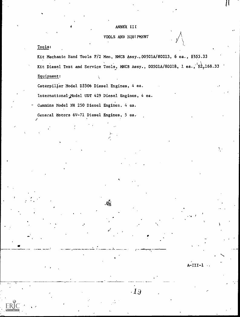
TOOLS AND EQUIPMKNT
Tools:
Kit Mechanic Hand Tools F/2 Men, NMCB Assy.,00501A/80013, 6 ea., $553.33
Kit Diesel Tett and Service Tools, MNCB Assy., 00501A/80018, 1 ea.,J$1168.33
Equipment:
Caterpillar Model D3306 Diesel Engines, 4 ea.
Internationalodel UDT 429 Diesel Engines, 4 ea.
Cummins Model NH 250 Diesel Engines. 4 ea.
General Motors 6V-71 Diesel Engines, 5 ea..
, 1
1 d
. N
11

ANNEX IV
TRAINING AIDS AND DEVICES
Films:
OPE-001, "Operation flour Glass," Cummins Engine Co., (27 min)
TF-552368, "injector Timing for GM Diesel Series "71" using 70,80 and 90mm Injectors."
Slides:
Slide Series - Showing proper procedures for installing Kiene TestEquipment in the engine.
Slide Series - Showing proper tune-up prodedures for Cummins NH 250Diesel Engine.
Transparencies:
GM Diesel Valve Adjustment 1
Setting Injector Height, GM Diesel EngineCaterpillar Fuel I"ump Lifter Construction
Wear Between Caterpillar Injection Pump Plunger and Lifter Yoke,Caterpillar Fuel System (Fuel Flow)'Examples of Cateipillar Rack to the PumpsTiming the CaterPillar'Rack to the PumpsSetting Caterpillar Pump Lifter Height
Locally Prepared Materials:
1. Job sheets.
a. SCBT-334.2-CM-JS-1.2.1.1, "Diesel Engine Tune-Up, Cumminswith P.T. Fuel'System."
b. SCBT-334.2-CM-3S-1.2.1.2, "Diesel Engine TuRe-Up, Inter-national, with Roosa Master Fuel System."
c. SCBT-334.2rCM-JS-1.2.1.3, "Diesel Engine Tune-Up GM Inlineand y6-71."
2. Class Notes.
a. SCBT-334.2-CM-CN-1.1.1.1, "Introduction-and-Safety Precautions."
b. SCBT-334.2-CM-CN-1.2.1.1i "Engine Overhaul (Diesel) II."
A-IV-1

I
A.
16mm Movie Projector
135mdt Slide Projector
Movie Screen
ANNEX V
TRAINIk AIDS EQUIPMENT
r,
A
. .
A-Y-1
,o,

r
..
None
,
,
'I
\
r-
...
MNEX VI,
FORMS
-
)
t
I
WA
,
.,
4.
4
,. I
--
...
,
A
4
A-VI-1 -I.
,

ANNEX VII
Mk..1ER SCHEDULE
TOPIC NO. TYPE PERIOD TITLE
FIRST WEEK
FIRST DAY'
SECOND DAY
1.2.1
THIRD DAY
q 1
C 2
3
4
56
7
C 8
9
10
11
12
13
14
1.2.1 C 15 '
16
17
18
. 19
20
21
FOURTH DAY
1.2.1 P 22
23
24
25
26
27
28
'FIFTH DAY
1.2.1 P 29
30
'RATIO
Introduction and Safety Precautions 12/1Engine Tune-Up (Diesel) II ' 12/1
Engine Tune-Up (Diesel) II 12/1
Engine Tune-Up (Diesel) II 12/1
Engine Tune-Up (Diesel) II 12/1
Engine Tune-Up (Diesel) II '12/i
A-VII -1

_.
Annex VII, Con't.
PERIOD
-
TITLE RATIOTOPIC NO. TYPE
SECOND WEEK
FIRST:DAY
1.2.1 P 1 Engine Tune-Up (Diesel) II 12/1
3
4
5
6
7-
SECOND DAY
1.2.1 P 8 Engine Tune-Up (Diesel) II 12/19
10
11
12
1314
THIRD DAY.
1.2.1 15 Engine Tune-Up (Diesel)-II 12/116
17'
18
19
20
FOURTH DAY
1.2.1 P 22 Engine Tune-Up (Diesel) II 12/123
24
25
26
27
28
FIFTH DAY
1.2.1 P 29 E gine'Tune-Up (Diesel) II 12/130
/

Annex'VII, .Con't.
Total Classroom Periods: 20
,Total Practical Periods: 40Total Period: 60.Total Weeks for Course: 02 WeeksNOTE: Each period represents one contact hour
i
-
*
\
,
r
,
,
/
I
2z)
AVII-3
,
N
...1....
A
I
i
tt
).

-A
.,
SCBT-334.2-CM-IG-1.1.1
NAVAL CONSTRUCAON TRAINING CENTER\
PORT HUENEME, CALT,FORNTA 91043SPECIAL CONSTRUCTION BATTALION TRAINING COURSE (SCBT)
Classification: Unclassified
Topic: _Introduction and,Safety,Precautions
Average Time: 1 Period (Class)
Instruaional Materials:
A. Texts: 'None.
B. References.
1. NCTCINST 5400.4, (Current SAries), Organ-izational Manual of NCTC.
Ale
,2: "Safety Practices for Shore Activities,"NAVMAT P-5100 (Jan 73), Chapter 5.
C. Tools and Equipment: None..
D. Training Aids and Devtoes.
1, Information &eta.
a. kBT-334.2-CM-IS71.1.1.1, "Introduction."
b. SCBT-334.2-CM-IS-1.1.1.2, "GeneralHousekeeping."
E. Training Aids Equipment: None:
4
e-/
S.
tv
Terminal Objective: Upon completion of this unit eachstudent will have registered,for the course, receivedtextbooks, complied with NCTC and CBC regulaeiOns governihe reporting and fighting of fires and shop safetyprocedures which pertain to him as a student at Special'
. Construction Battalion Training.
(0.1
Enabling-Objectives: 'Upon com letion of this topib eachstudent will be abel to answer oral4 specific questions'pertaining to the mission, regulations and organizationof the command, and the.method of repottinefighting.afire and the precautions to be observed td ensure person
safety as established by NCTC and CBC reguritions.
NOTE: Failure to( meet tbig objective is not considered
disqualifying. Information sheet will be kept in
possession of.student for use if needed.
Criterion Test: Each student will answer orally specifiquestions pertaining to the mission, regulations and orgizatiOn of the command, and the method of reporting/fighting a fire and the precaution to be observed toensure personnel safety as established by,NCTC and CBO
regulations.
Homewdrk: None.'
)
27_
.4.
4Nr'
(
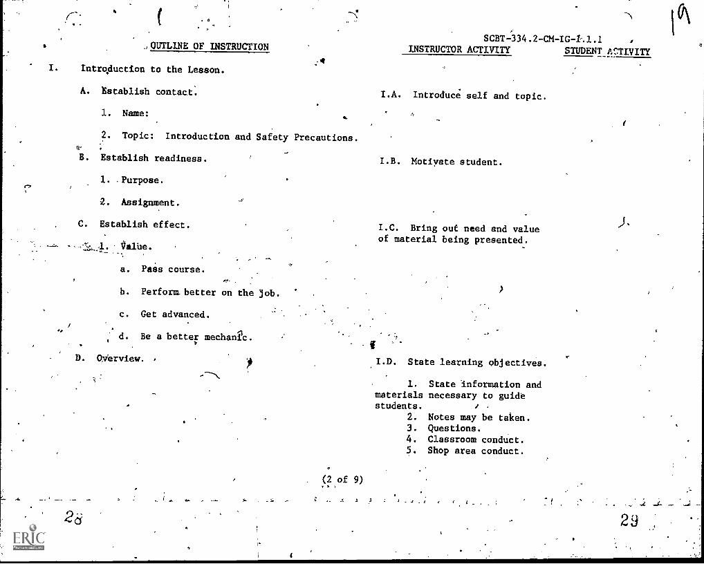
SUIT --334.2 -CM -IG -4.1.1 .a qOUTLINE OF INSTRUCTION INSTRUCTOR ACTIVITY STUDENT Ar.:TIVITY
I. IntroAuction to the Lesson.
A. tstablish contact.
1. Name:
2. Topic: Introduction and Safety Precautions.
B. Establish readiness.
1. .Purpose.
. Assignment.
C. Establish effect.
:talUe.
a. Pass course.
b. Perform. better on the job.
c. Get advanced.
d. Be a better mechanic.
D. Overview.
WO.
(2 of 9)
I.A. Introduce self and topic.
s_
I.B. Motiyate student.
I.C. Bring out need and valueof material being presented.
I.D. State learning objectives.
1. State information andmaterials necessary to guidestudents. .
2. Notes may be taken.3. Questions.4. Classroom conduct.5. Shop area conduct.
2 9

4
P /4:11
OUTLINE OF INSTRUCTION
II. -Pretentation:
A. Introduction.
1. Mission.
a. Special training course.
,
b. Higher state of readiness.
I
2,e)SCBT -334.2 -CM -1.1.1
.INSTRUCTOR ACTIVITY STUDENT ACTIVITY
c. Compliance with COMCBPAC Instructions.
1.b. Stress.
2. Organization and chain,,qcommand. A.2. W.ve names afyippropriate,
a. Commanding-Officer.
b. Executive Officer.
c. Training Officer.
*d. School Department Officer.
e. Division Director.'
f. Senior Instructor.
g. Primary Course Instructor.
,h. Class Petty Officer.
i. Class Safety Petty Officer.
3. Regulations and policies.
a. SChedule.c
Ata.
a. Issue SCBT-334.2-CM-e IS-1.1.1.1, and SCBT-334.2-CM-
IS-1.1.1.2.
(3 of 9)
4
1.
,
L.4.

,OUTLINE OF INSTRUCTION
b. Break procedures.
c. Uniform regulations.
(1) Working uniform of the day. s
d. Absenteeism.
(1) Must be kept to a minimum.
(2) Medical or dental sick call.
(3) Permission to be absent.
e. Parking,
(1) Where.
(0) When.
(3) Haw.
f.. Visitors and phone calls.
(1) Emergencies only.
(2) Phone numbers.
g.
(a) School.
Lost ordamaged material.
(1), Textbooks.,
(2) Publications.AI (4 of 9)
SCBT -334.2 -CM -IG -1.1.1
INSTRUCTOR ACTIVITY STUDENT ACTIVITY'
3.c. Maintain a military appear-
ance at all times.
d.(2) Stress.
_I... ....MM. /,
ci
/-3

OUTLIIIE OF IMTRUCTI9N
(3) Tools.
(4) Materials.
(5) Statement of charges.
h. Off-limit areas.
(1) Restricted.
(2) Hard hat.
i. Plean-up procedures.
j. Problems.
(1) Scholastic.
(2) Personal.
(3) Co4nseling assistance.
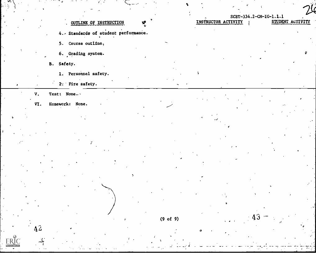
4. Standards of student performance.
Written examinations.
b. licaework assignments.
c. Practical application.
5. Course outline.
-a. Mission of comae.
b. Course objectives,.
c. Reading assignments.,
SCRT -334.2 -CM -IG -1.1.1
INSTRUCTOR AcTryTTx STUDENT ACTIVITY

OUTLINE OF INSTRUCTION
d.' Class schedule.
6. Grading system.
a. Homework.
b. Practical application.
c. Quizzes.
d. Weekly tests.
e. Final examination.
B. Safety precautions.
1. Personnel safety
.y!
SCBT -334.2 -CM -IG-1.1.L
INSTRUCTOR ACTIVITY STUDENT ACTIVITY
A.6. Unless otherwise specifiedtrainee achievement will beevaluated by a combination of oralquizzes, written test and pragticalperfo ce evaluations. 1Studentsmust lit all learning objectivesin order to pass.
B.1. Relate personal experienceif applicable.
a. Tripping hazards.
,(1) Tools and equipment. a.(1) Stress.
(A) Hand tools.
(b) Jacks.
(c) Creepers.
(d) Foreign objects.
(6 of 9)
34/

OUTLINE'OF INSTRUCTION
b. Slippage hazards.
(1) Oil and grease.
() Water.
(3) Paper.
c. Eye hazards.
(1) Face mask, goggles.
(2) Hammering, chiseling.
(3) Grinding.
(4) Servicing batteries.
d.- Compressed-air hazard.
(1) Eye and face.
(2) Skin penetration.
SCHT.334.2-CM-IG-1.1.1INSLaUCTOR ACTIVITY STUDENT ACTIVITY
e. Reporting accidents.
Class Safety Man. ei(1) Introduce class iafety
"ma n.
(2) Instructor.
(3) SChool director.
(4) First aid when appfbpriate.
2. Fire -safety.
4'
(7 of 4) \';

OUTLINE OF INSTRUCT,R
a. Avoiding and preventing fires.
(1) Good'housekeeping. a.(1) Seress.
SCBT -334.2-M-IG -1.1.1
INSTRUCTOR ACTIVITY STUDENT'AtdIVITY /
(2) Proper storage of materials.
A(3) Smoking.
b. Know evacuation routes. : 2:b. Explain in detail evac-
uation route.
(1) Classroom.
(2) Shop area-
c. RepOrting fire.
(1) Location of fiie alarm switch.4
(2) Report to class safety man.
d. Fighting fire.
(1) Location of extinguishers.
III. Application - oral questions.
'IV. Summary:
-
A. Introduction.
1. Mission.
2. Organization.
3. Regulations. ,
( of 9)
-401,
6
. OUTLINE Or INSTRUCTION
4. Standards of student
5. Course outline.
6. Grading system.
B. Safety.
1. Personnel safety.
2'; Fire safety.
04.
performance.
SCBT -334.2 -CM -IG -1.1.1
INSTRUCTOR ACTIVITY STUDENT AcTIiITY
V. Test: None..-
VI. Homework: None.
.o
3
(9 of 9)
4
43
4-r

adapting this material
MODIrICATIONS
of this puhlication has (have) been deleted in
for inclusion in the "Trial Implementation of a
Model System to Provide Military Curriculum Materials for Use in Vocatlonal
an ret kwtcui E ucation. Deleted Mnterial involves extensive.use of
military forms, procedures, systems, etc. and was not considered appropriate
,for use in vocational and teChnical education.
/44

SCBT-334.2-CM-IS,1.1.1.2
NAVAL CONSTRUCTION TRAINING CENTERPORT HUENEME, CALIFORNIA 93043
SPECIAL CONSTRUCTION TRAINING COURSE (SCBT) 334.2
rta. RMATION SHEET
Title: General Housekeeping
1. Cleanliness.
a. ,Floors,and other exposed areas,//'
(1y)The distribution center, garage or workshop shall be thor-oughly inspected dailyand maintained in'a clean and orderly statd: FlOorsand other exposed surfaces shall'be kept scrupulously clean, Hazardson,floors such as.oil,,grease or loose tools, which might result infire, slipping', tripping or falling tha)l be_eliminated as quickly aspossible.
b. Grease'Rack.
(1) Particular care shill be taken to maintain cleanliness inarea around the grease rack as well asuin the rack itself. Be sure thatgrease connections are fast to car connections when greasing A car. Atthe close of work each day, clean and grease rack and floor.
2. Ventilation.
a. Garages and repair shops shall be well ventilated for protectionof service personel agains accumulations of carbon monoxide. If thesespaces are not equipped w th adequate ventilation, doors shall beopened wheneer engines ar running.
3. Illumination. \*....."
VP
a. Adequate illumination shall be proliided and utilized for all, general work areas, including work benches and lubrication.pits.
4
4. Safety During Repairs.0
,a. Use warning signs or barricades to protect personnel when con-struction, repair work or painting is in progress.
5. Avoiding Trippfhg Hazards.. ,
.
a. Covers on sidewalk, boxes, fuel tanks and pipe openings shallbe flush with surfaces and shall be kept closed when not-in use: Alltools and equipment,shall be'kept in their proper places when npt in useand shall part-cularly be kept out of walkways ço avoid"tripping hazirds.
(1 of 4)

PROTECTION OF PERSONNEL
2-'61
SCBT -334.2 -CM -IS -1.1.1.2.
-2
.The followinA personnel protective equipment shall be used byworkmen in a distribution center, garage or workshop.
1. APparel Required.
a. Mechanics shall wear goggles or face shilds, rubber gloves,aprons, safety shoes and special gloves as needed.
2. Goggles.
a. Goggles shall be wormfor all grinding, welding, chipping,cutting and when using compressed air, or for similar operationsdesignated by local command. The object of tinted filter linses is nbtonly to diminish the'intensity of visible light to a point where glareis reduced to a minimum so that the.welding zone can be readily seen,but also to protect the welder from harmful infrared and ultravioletradiation from the arc or flame.
3. Prohibited_Apinst Rings.
a. Rings shall not be worn by workmen servicing batteries orworking on motor vehicles.
FfRE PREVENTION
1. Fire-Fighting Apparatus.
a. Fire fighting apparatus shall be kept in proper working conditionand wefi distrubited with locations marked in accordance with NAVDOCKSP-309, Application of Color to Shore Establishments. Garage personnelshould be trained in the operation of this equipment.
2. Smoking.
a. Smoking o the car ing of lighted- pipes, cigars or cigarettes
near pumps, batt ies or ven pipes shall be prohibited.
EQUIPMENT AND TOOLS
The per inent precautions of Chapter 14 apply in addition to therules in thi chapter.
1. General Rules.
Keep tools in their proper places when not in use.
b. Use only the correct tools for a particular job.
(2 of 9)
4 6

a 4.
c. Never use defective tools.
SCBT -334.2 -CM -IS -1.1.1.2
d. Keep tools and hands free of grease. Clean tools with an
approved solvent..
e. "When wang a her on springs, work bar away from.the face.,
f. Lift small batteries witAktery straps designed for this'purpose. On large batteries use i ated lifting bridles designed for
this purpose. 0
2. Blow Torches.
a. Blow torches shall not be used,to clean crankcase, transmission,radiators or.grease guns; steam, hot water or other suitable degreasersshall be employed for this purpose.
,0
3: Grease Guns.
-a. Grease guns must be.handled carefully and used onlrfor thepurpose intended. Serious injury has resulted when grease has been shot
out of a grease gun in horsepla). NEVER point the gun toward another
person.
4. Lube Dispenser.
4. Keep 'ethe dispenser where it Will be put of the way and checkit at regular intervals for leaks.
5. MAile Grease Cart.
a. The mobile grease cart must returned to it's proper placeimmediately after it is used and.the hose must never 'be left lying alongthe floor.
REPAIRING AND SERVICING6fEHICLES
1. Bodi and Engine Work.
a. Entering the garage. When a car is ,being driven into a garage
personnel shall stand well out of it's path. Nevery try to service a
moving vehicle.,
-SecUring the hood. ldork -shall not-be started under a hood ofa vehicle unless Ole hood has been firmly secured in the open position.Hood holddown clamps qx locking devices shall be kept in good condiiion.Additional holddown clampsShould be installed where necessary,
(3 of 9)
47

SCBT-334.2-CM-IS-1.1.1.2
. c. Broken glass. Care shall be t4en to avoid injuries frombroken windshild, light globes, lenses or jagged pieces of metalaround the car,
d. Radiator. If,the radiator is steaming, the hands should beprotected with a large rag, and the steam allowed to escape beforeremoving the cap entirely. Matches shall not be used when looking intoa radiator.
e. Cradking the engine. If it is necessary to crank an engine byhand, the brake must first be.set and the gearshift placed in,neutral.In cranking the handle should be grasped with the.thumb alongside thefingers and not around the crank. If possible, start the engine by aseries of quick pulls. Spinning should always be started with anUPWARD PULL; never with'a downward thrust.
f. Lifting heavy parts: To prevent-personal injur:y whenremoving or replacing heavy Pb:rts, such as gear units or hub and drumassemblies, mechanics should always use a hoist, jack or dolly.
g.r Restriction on leaded gasoline. Do not use gasolinecontaining tetraethyl lead for anything but motor fuel. If this typeof gasoline is spilled ph the body, wash it off thoroughly; as it is adeadly poison.
2. Vehicle Stands. Approved metal vehicle,stands shall always be usedwhen work is being done under a vehicle from wipich the wheels have beenremoved. Wooden blocks or horses shall not be used for this purpose.Hydraulic lifts are permisgible:
3. Dump Trucks. Before starting repair on a dump truck; with the dumpbody in.a raised position, the body'shall be secured by inserting thesafety pins in the safety loeks or in the absence of such locks, the bodyshall be secured with sturdy block" or triangular steel stands designedfor this purpose.
4. Working on Raised Vehtcles.
Jacks.
(1) Inspection. Jacks shall be inspected visually for cracks,looseness and wear. If there is any doubt about the condition of ajack; it must not be used.
-
(2) BloCking. 8e certain that a vehicle is properly blockedwhen working uhder it. Do not depend entirely on jacks.
(3) Centering. Center the service jack on theaxle when a wheelis to'beiremoved from a car. The jack should always be set on a solidfooting.
(4 of 9)4'

'
SCBT -334.2 -CM -IS -1.1.1.2
(4) CapavIty. Never lime a jack for a load In excess of qt's
rated capacity.
(5) Handle. Place the jack so that the swing of it's handle
will be unobstructed, Never leave a jack standing Under a load,with thehandle in the socket.
(6) Keeping clear. Never lean over a jack handle or handle'socket under load. Keep the ,body clear ofafthe car, in case it should
suddenly start to roll.
h_ Hyd-eautir 11ts.
(1) Inspection. Inspect hoists at regular intervals for oilleaks, oil level and proper lubrication. Check overhead connections atregular intervals and make frequent inspections of safety lodks on.gears;the teeth of gear locks should not be worn or chipped. Never Use a
defective hoist.
(2) Putting vehcilé on lift. Do not stand in front of a hoistwhile'a motor vehicle is being guided onto it.
. (3) Securing fiehicle. Never permit occupants to remain in avehicle when it is to be lifted. 8e ture, before lifting a vehicle,that the ignition is off, the gears are in neugral, the wheels are blocked,and the doors are closed.
(4) Freewheel lift. If.the freewheel type of lift is used, besure that ehe car is properly balanced. Raise the lift just enough ,to take the weight off.thefidieel, check the blocks and knee-actionplates to determine whether the car is resting Properly and set thehand brake
(5) Raising the hoist.
.(a) When the hoist is raised, use the safety leg and_Check to see that safety datches are secured.
(b) Never rOck the car when the hoist is raised.
(c) Raise and lower the car slowly. Do not try to rush theaction of the hoist, as the gears may slip.
(d) Docnot attempt_to,raise a vehicle that.may-be heavierthan the capacity of the hoist,
(e) Except for eleanifig purposes, never raise the hoistwhen it'is not in use.
(6) Selfobjects, stand inthe object should
0 0
protectioh during work. When working on,raisedsuch a position that your feet will not,be crushed iffall.
(5 of 9)
I.
KS
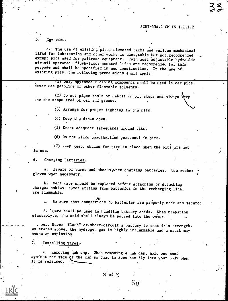
Car pits.
SCBT-334.2-CM-IS-4.1.1.2
a.- The use cif existing pits, elevated racks and various mechanicallifts for lubrication and other works is acceptable hut not,recommendedexcept pits used for railroad equipment. Twin most adjustabfe hydraulicair-oil operated, flush-floor mounted lifts are recOmmended for thispurpose and shall be specified in new construction. In the use ofexisting pits, the following precautions shall apply:
Only approved cleaning compounds shall be used in car pits.Never use gasoline or other flammable solments.
(2) Do not place tools or debris on pit steps'and alwaysthe the steps free of oil and grease.
(3) Arrange for proper lighting in the pits.
(4) Keep the drain open.
(5) Erect 'adequate safequardt-arOund pits.
(6) Do not allow unauthoriZed personnel in pits.
in use.(1) Keep guard chains for pits in place when the pits,are not
6. Charging Batteries.
a. Beware of burns and shocks)when charging batteries. Use rubbergloves when necessary.
b. Vent caps should be replaced before attaching or detachingcharger cables; fumes arising from batteries in the recharging line .
are flammable:
fiec. Be sure that connections to batteries are properly made and secuted.
d: 'Care shall be used in handling battery acids. When preparingelectrolyte, the acid shall always be poured into the water.
4e._ Never---ufiash" -or.short-circuit a battery to test it's strength.As stated above, the hydrogen gas is highly inflammable and a spark maygause an explosion.
7. Installing Tires.,
a. Reinoving flub cap. When removing a hub cap, hold one tindagainst the side f the cap so that is does not fly into your body whenit is released.
(6'or 9)
5u
,
1-
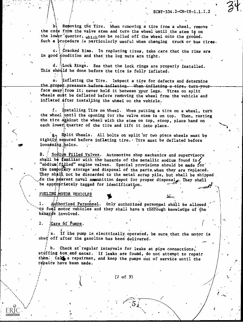
! I:4 Re oving the Tire. When removing a tire from a wheel, removethe cotie fr m the valve stem and turn-the wheel Until the stem i onthe lo4r cIuarter, whichcan be rolled off the wheel onto the ground.Such a ii.ro edure is particularly useful when changing truck or bus tires.
c.t racked Rims. In replacing tires, take care that the rims arein good' iondit1bn and that'the lug nuts are tight.
SCBT-334.2-CM-IS-1.1.1.2
d. ;Lock Rings. See that the lock rings are properly installed.This shOtild be done before the tire is fully inflated.
7
e: 7nf1ating the Tire. Inkpect a tire for defects and determineSI o oo. I. -
face awaylfrom it; never hold it between ypur legs. Tires on splitwheels mu4t be deflated before renioving the wheel from the vehicle andinflated Oter instalAing the wheel oft the vehicle.
i
7
f. Tinstalling Tire on Wheel. When putting a tire on a wheel, ttirn. the wheel tuntil the opening for the valve stem is on top. Then, resting
,the tire 4tinst the wheel with the stem on top, stoop, place hand oneach loweriquarter of the tire and lift it into place.
;.,
. 1
al Split Wheels. All bolts on split'or two piece wheels must betight,lyE/ se;eured before inflating tire.. Tire must be deflated beforeloosAnihgpolts. ,-
I 1"8. i Soailim Filled Valves. Automotive shop mechanics and supervisorsshall be familiar with the hazards of the metallic sodium found in!!
' "aodiumlfIglied" engine valves. Special provisions should be made for'.0 the te44ary storage'and disposal of the parts,when they are reOlaced.
They shell not be discarded to the metal scrap pile, but shall be shipped_-,
,,.. in the nciarest naval ammunition depot for proper disposal , They shall
,
4 r i ,Of ,tt.
be appropriately tagged for identification.gorir 4 /
% 9% FUELIN44WOR VEHICLES% 1
..t.4;
% ! 7-r
1. A4thorized Personnel. Only authorized personnel shall be allowed.full motor vehicles and they shall have t thorough knowledge of the
hattrlia involved.r
2. ICare 6f.Fumps. ,f ,
,
..
,a. If the pump is electrically operated, be sure that the motor isshu5' off after the gasoline has been delivered.
_..-;
1 b. Check aeregular intervals for leaks at pipe connections;4
st4ffing box,and meter. If leaks are found, do not attempt to repairthIhm:. Ca4110 repairman, andY keep the pumps Out of serviCe until therepairs hive been made.
(7 of 9)

.4
c. Have the base bolts secure
d. Do ,not attempt to makeserviceman.
3. Using Fueling Equipment.
* a. Equipment'Mainttnance.faucets. Arrange for them to be
.
et
44
SCBT-334.2-bM-IS-1.1.1.2
a
at all times.
electrical repairs on pumps. Call a
Do not uie leaky hose, pumps, valves orrepaired at once.
b. Gasoline Containers. Gaaplineunlabeled t ntainers; metal safety, cansis to be ca ried away, it shall be done
capped.ahd eul.tably marked
shall not be left standing inmust al,ways be used. If gasolineonly when in-the'metal safety
c. 4utomatic Dispensing Nozzles. Automatic shut-off dispensingnozzles m y be used without attendanc4, only if the nozzles are approvedand .4sted as such, with limitation by the Underwiter's Laboratories, Inc.(41hen such nozzles are,ysed,without attendance, the allowing precautions'shall be observela'
,
(l) The engine and lighis of'the vehicle being fueled shall beshut off.
1
extensions oi operating internal combustion enginesten feet from tile point of fuel delivery.
!
(2) Exhaustshall be at'least
(3) Each automatic shuti!off nozzle shall be chtcked Aaily byattendanta far wear ot damage, Oen be checked weekly by the stationfi're department personnel, and ritmoved and repaired or adjuated by amanufacturer's representative af aix-month intervals'or after50,000 cyaes.,13I:vpesation; whikhever comes first. Records of 'theseinspections shap. be keRt-by.siie service station.
%
/ (4) A 50 pound wheied CO2 or '30.pound dry chemical extinguishershalVbe provided at each'service station 'where such nozzles are used.
1 (5) ZttendanftS shall be fully instructed in the regular inspectionoffthe automatic ahut off nozzles and the hie of the fire extinguishers.
'(.T FUell,ftg 'Frocgdures.4
74
,ra. Bonding. To prevent electrical static discharges, tank and
nozzle shall be kept in"metallic contact while gasoline is being poured,/ into the fuel tank? This rule applies to all kinds of motor vehiclea
and expecially toogasoline trucks.4

filb
-
er
b. Proximity of Annterinas. fueling of moti4PVehid1es in, the
proximity of annienas and antenna do leads should be avoid d orN
conducted with special precautions. An ungrounded automobile ungrounded
filling nozzle or pe5e1y the attendantis body n. close proximtyJo
tranHmitting antennom and ciown leadH, may.produce 'sparks sufficient to
ignite gasoline vapur When the nozzle comes in contact with the t nk
opening. Pump nozzles must be grounded at all timdil and motor .v hicles,
when fueling, must also be grounded before,opening the tank.
c. Danger from Fuies:- To minimize the effects of gasolinefumePol
the face should be turned away, from the fuel pipes while making/
. deliveries of gasoline Always drain the nozzle befere removing it
from the tank of a ve I
s
d.. Batter Terminals. If theiasoline taiulZil located
seat, do not permi't theinozzle to-toudn the battery termin
e.IDanger of Oveifilling. Take special care that fuel tankp a__
not filled to overflowing. This is particularly important in the A
er the
case of motorcycles.
5. Fire During iueling.
a, If fire should break out in the'fuelterve the hose from the tank immediateiy andCO , dry chemical.or foam extIngjmhers, dirt(preferably chamois, If it is ailable).
,
1, After-Fuq.ing Procedures'.
, .
t..
'.)
a. Caps and Plugs. Replace caps or bplus securtly immediately
after using drums or barrels coneaining gasyline. Caps and plugs should
be in place when drums or barrels ar - pty and these containers should
be removed from thd garage as soon ae ossible. '
b. Pumps. If the gasoline pumP is of the visible bpwl type, drain
spout duripg-gueling,smother the fire withsand or a wet cloth
the gasoline from the bowl when.securing the pumps.
:$4.
c. Measuring Cans. Turn emptyem thoroughly before storing them.
d. Personal Hygeine. After han
their hands thoroughly before.eating.with gasoline should be.changed immedand dermatitis of the skin. Gasoline
in the pocket.
(9 of
eaguring cans bottom up and dry.'
ling gasoline, mechanics should washClothing that has become soaked
ately, to prevent possible burnssoaked rags 'should never be carried
9)
r4
J

/,
SCBT-334.2-CM TG-1.2.1
NAVAL CONSTRUCTION TRAINING CENTER,PgRT HUENEME, CALIFORNI4 93043
SPECIAL CONSTRUCTION-BATTALION TRAIN G COURSE (SCBT) 334.2
4
Classification; 'Unclassified
Topic: Engine Tune-Up (Diesel) II
Average Time: 19 Periods (Class)40 Periods (Pract)
Instructional Materials:
11"Texts:
1. Roosa-Master Fuel Injection Pump forinternational Diesel Engines from
ISS-1042-1.
2. International 429 Series Diesel Engine,
' ISS-1503D.A')
3. Cummins Tune-Up and Trouhle-ShootingBulletin No. 983643-CE.
A. Operation and Adjustment PT Fu\l,
System Bulletin No.agowatio,
5. Caterpillar Service Manual.
6. In-Line 71 Engines Engined DetroitDiesel Maintenance-68E177.
B, References.
1. None.
5 4 .
Tiininal Objective: Upon completion of this course eachs udent will be able to restore diesel engine performancet manufacturer's specifications through troubleshooting ana alyzing diesel engine fuel systems in their entirety whilma ing minor and major adjustments to those components thatdirecty effect engine performance. Procedures.will be
outlined in a job sheet. Each student will use approp-riate.handtools, special tools and shop equipment to test,adjust and replace fuel system components that fail tomeet manufacturer's specifications. All performance willcomply with Manufacturer's specifications without deviationas specified in the job sheet.
Enabling Objectives: Upon,completion of this,topics eda
student will be able to restore diesel engine performanceto manufacturer's specifications through troublshontingand analyzing diesel engine fuel systemi in their entiretyhile making minor and major adjustments to those component
ithat directly effect engine performance. Procedures will b
outlined in ajob sheet. Each student will use approp-riate hand tools, special tools and shop equipment to test,.adjust and replace fuel system components that fail to meetmanufacturer's specifications. All performanCe will complywith manufacturer's specifications without deviation as
specified in job sheet.
(1 of-43)
.55

C. Tools and Equipment.
1. Tools.
a. Mechanic Hand Tools Kit, F12 men,NMCB Assy.
b. Aiesel Test4and Service Tools Kit,NMCB Assy.
2. Equipment.
a. Caterpillar Model D3306', Diesel Engines.
b, International Model UDT 429, Diesel Engine.
c. Cumming/Model NH 250, Diesel Engine.
d. General Motors 6V-71, DiesellEngine.
D. Training Aids and Devices.
1. Films,
a. "Operation-Hourglass," Cutmins Engine.Company.
b. -TF-5572368, "Injector Timing for GMDiesel Series "71" using 70, 80,and 90MM Injectors."
SCBT-334.2-CM-IG-1,2.1
Criterion Test: Tune a specified diesel engine to re-store engine performance to meet manufacturen'sspecifications, using appropriate handtools, special toolsand shop equipment. He will adjust valves, get low andhigh idles, troubleshooting, analyze and isolate dieselfuel system malfunctions. All.performance will complywith manufacturer's specifications without deviationas specified in the job sheets SCBT-334.2-CM-JS-1.2.1.1and SCBT-334.2-CM-JS-1.2.1.2.-
Homework: ,None.
7
2.
(
Traniparencies.
a. GM Diesel Valve Adjustment;)
b. Setting Injector Height, GM Diesel .
Engine. n)(2 of 43)

c. Caterpillar Fuel Pump.Lifter Conatruction.
d. Wear between Caterpillar Injection PumpPlunger and Lifter Yoke.
e. Caterpillar Fuel SyStem (Fuel Flow).
f. Examples of-CaterPillar Rack Settings
(3H1690).,
g. Timing the Caterpillar Rack tO the Pumps..
h. Setting Caterpillar Pum1),Lifter Height.
3. Slides.
a. Series of'slides showing proper proceduresin installing Kiene test equipment on theengine as illustrated in section 2,pp. 39 - 43, in service manual for Inter-
national Diesel Engines, Form ISS.4042-1.
b. Series of slides showing proper tune-upprocedures for Cummins, N11250 as outlined
in Cummins Tune-Up and TroubleshootingBulletin No. 983643-CE 3-71 pages and'illustrations as required.
4. Locally Prepared Materials..
a. Job sheets.
(1) SCBT-334.2-CM-JS-4.24.1, "Diesel Engine
.Tune-Up Cummins with P.T. Fuel System."
(3 of 43)*
5
SCBT-334.2-CM-IG-L2.1
5 9

r-
(2) SCBT-334.2-CM,JS-1.2.1.2, "Diesel EngineTune-Up, International with RoOsa MasterFuel System."
(3) SCBT-334.2 -CM -JS -1.2.1.3, "Diesel Engine
Tune-Ups GM In-Line and V6-71."
b. Class Notes.
(1) SCBT -334.2 -CM -CN -1.2.1.1, "Engine
Overhaul (Diesel) II."
(4 of 43)
SCBT-334.2-CM-IG-1.2.1
6i

OUTLINE OF INSTRUCTION
I. Introduction to the Lesson:
A. Establish contact.
1. Name:
2. Topic: Engine Tune-Up (Diesel) II
B. Establish readiness.
1. Purpose.
2. Assignment.
C. Establish effect.
1. Value.
a. Pass course.
b. Perform better on the job.
c. Get advanced.
d. Be.a better Mechanic.
D. Overview.
(5 of 43)
SCBT -334.2 -CM -IG -1.2.1
INSTRUCTOR ACTIVITY STUDENT ACTIVITY
I.A. Introduce self and topic.
I.B. Motivate student.
I.C. Bring out,need and value
of material being presented.
I.D. State learning toOectives.
1. State information andmaterials necessary to guide
student.
6 S'

OUTLINE OF INSTRUCTION
II. Presentation:
A. General checks.
NOTE: The following items are common to mostengines and should be checked prior toactual work of engine tune-up.
1. Air systems.'
64
a. Air cleaner.
(1) Dry type.
(a) Blow clean with low pressureair from inside to outside.
(b) Replace if oil soaked or showsevidence of any holes.
(2) Wet type.
SCBT -334.2 -04 -IG -1.2.1
INSTRUCTOR ACTIVITY STUDENT ACTIVITY
II.A. Demonstrate these checkson any actual engine applic-ation, either test standmounted or actual piece ofequipment.
A.1. Perform generalchecks prior to tuninga'specific engineeither test standmounted or,aFtualpiece of equOment.
(a) Wash thoroughly in solvent and !
dty.
(b) Refill only to manufacturer'sspecifications.,
b, Aelated piping. 1.b. Explain the,importanceof having a clean'air system.
(6 of 43)

OU'LINE OF INSTRUCTION
(1) Inspect hose and clamps for tightness
and damage.
(2) Inspect accessible gaskets on air
connections and intake manifold.
NOTE: Dirt entering the air system can ruin
, any engine in very short order.
2.: Turbocharger and manifold piping.
a. Inspect for any signs'of excessive passinthrough the turbocharger seals.
b. Consult manufacturer's manual forprocedurei to troubleshoot turbocharger
c. Inspect turbocharger oil supply and d ain
lines for kinking abrasion or other
damage.
3. External fuel system.
a. Check for fuel in fuel tank.
b. Inspect.all fuel lines for kinks, leaks
or abrasion damage.
c. Check fuel filters, change if/needed.
4. V-belt drives.
a. Maintain proper belt tension as required
by manufacturer.
k(7 of 43)
SCBT -334.2 -CM -IG1-1.2.1
NSTRUCTOR ACiIVITY STUDENT ACTIVITY
+e,
.2. Stress proper care ofturbocharger and related
components.
.4
kl--410

OUTLINE Of INSTRUCTION
b. Replace worn belts.
5. Batteries.
Check terminals, clean if.required.
Proper,electrolite level.
B. Caterpillar engine tune-up procedures.
1. yValve adjustment.
a. Bring engine qp to operating temperature.,
b. Remove valve covers.
c. Position number one cylinder to T.D.C.4
NOTE: If 'ueliIgthe "Buddy throw" method, You
may start withognY Cylinder in the enginefiring order provided that cylirider is.on-T.D.C. and it's running mate is in the rock'
* .position.
d, Using a feeler gauge of a specified thicknessset both the intake and exhayst valves ofthat cylinder.
e. Set the remaining valves in the normal firingorder of the engine.
2. Compression release adjustment.
(8 of 43)
bTh
SCBT -334.2 -CM -IG -1.2.1-INiTRUCTOR ACTIVITY STUDENT ACTIVITY
B.2. Issile.Caterpillar ServiceManual and take class to shopand demonstrate procedures-forvalve and compression releaseadjustment.
.de'N
8.2. Observe demon-stfation and followprocedures in.manu-facturer's manual.
69
OUTLINE.OF INSTRUCTION
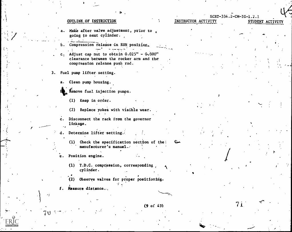
a. Make after valve adjustment, prior togoing to next cylinder.
b. Compression ielease-in RUN position,.
c: Adjust cap nut to obtain 0.025" - o,b1-go"
clearance between the rocker arm and thecompression release push rod.
3. Fuel pump lifter setting.
a. Clean pump housing.
'Remove fuel injection pumps.
(1) Keep in order.
(2) Replace yokes with visible wear.
c. Disconnect the rack from the governorlinkage.
d. Determine lifter,setting.,
(1) Check the specificationmanufacturer's manual-)
e. Position engine.
,
sdction of the:
(1) T.D.C. compression, correspondingcylinder.
. , 4
(2) Observe valves for proper positioning.J
f. ileasure distance.,
'4,,
(9 of 43)
SCBT -334.2 -CM -IG -1.2.1
INSTRUCTOR ACTIVITY STUDENT ACTIVITY

OUTLINE OF INSTRUCTION
(1) Pump housing top to lifter yoke
contact. point. A -
(2) Use depth micrometer.
g. *ustment.
(1) If variation exceeds 0.001".
(2) Use special wrench if availabie.
NOTE: 4o-insura lifter was set a proper positionrotate engine a few more degrees in thedirectioniof engine rotation and rectieckdistance. Distance should be lpss thanthe original reading:
h. Continue checking in normal firing orderof engine. ../
4. Fuel pump rack setting.
' a. DiscOnnegt the rack from the governorlinkage..
. (1) Eliminate governor spring tensionon the rack.
ib: Remove fuel injection pump.
(1) Nearest governor.
c. Insert rack setting gnoge 3H1690.
(1) Align the mark on the gear of tgle
, gauge with the mark on the fuel rack.
(10 of 43)
SCBT -334.2 -CM -IC -1.2.1-1
INSTRUCTOR ACTIVITY 'STUDENT ACTIVITY
11 0
"At
-
7 3

GI
OUTLINE OF INSTRIXTION
.d. Remove housing on rear of the fuel pump
housing.
(1) Gain access to the torque spring and
shims.
e. Determine correct setting.
(1) Refer to manufacturer's specifications.
f. Move fuel rack to full fuel position.
(1) Collar on thelLck touches but does
not move the torque spring.
g. Adjustment.
(1) Add or remove shiMs to obtain properrack setting On the rack in the correct
position.
NOTE: If shims are added or removed, be sure theparts are re-instated in the:proper location.
h. Remove gauge.
i. ReplaceInjettiOn
i
'(1) Align the mark on the pump plungergear segment with the mark on the
fuel rack.
Connect'fuel rack and governor linkage.
5. Governbr speed adjustment.
(11 of 43)
SCBT-334.2-CM-IG-1.2.1INftRUCTOR ACTIVITY . STUDENT ACTIVITY

OUTLINE OF LNSTRUCTION
a. Low bile speed.
(1) Turn idle speed screw.
(a) Top of governor housing.-
C100Wise to deirease the speed.
(c) Counterclockwise to increase thespeed. .
(2) Set to manufacturer's specifications.
b.r
High idle (governed speed) adjustment.
.(1) Tura high idle speed screw.
(a) Top of guvernor housing.
76
(b) Clockwise to decrease the speed.
(c) Countercloskcwise to increase thespeed.
a
SCBT -334.2 -Cm
INSTRUCTOR ACTIVITY STUDENT ACTIVITY
(2) 'Set to manufacturer's specifications. b.(2) Demonstrate fuel pumplifter setting,,rack bettingand governor speed adjustment.
(12 of 43)
b.(2) Direct Sad supervise,student particle in tune-upof caterpillar diesel engine.
,1
b.(2) Follow tune-upprocedures Whilefollowing steps givenin service manual.
b.(2) Follow demon-
stration whilerefering to step inmanufacturer'sminual.
77

OUTLINE OF INSTRUCTION
C. Cummins Engine Tune-up Procedures.
1. Injector removal, inspection and adjustment.
A'a Remove rocker covers.
NOTE: Check the inside of the coveys for,presence of water condensation.
la. -Looen the injedufr rocker levet adjusting
nut,on a1l cylinders.:' i
.c. Rotate engine until the first "VS" markon the pulley or damper is aligned Withthe index mark on the housing.
d. Take the adjusting screw out of thelcenter, rocker lever on the cylinder thatis T.D.C. Corresponding to "VS" marks, /
fri
e. Removg injector.4.
NOTE: If type "D" injector remove the link"B" and "C" type injectors the link is,not removable.
f. Inspect injector for any abnormal wear orConditions.
SCBT-334.2-CM-IG-1.2.1INSTRUCTOR ACTIVITY STUDENT
b.(2) Practicaterpillar engtune-dp using-manufacturer's man
g. Clean the cylinder head injector seat\fall carbon.
(13 of\43)
~P 9

.4"
OUTLINE OF INSTRUCTIONA
NOTE: A shaped stick and rag, or ersuitablecleaning krush will suffice for thisoperation. Never use any hard tool forthis procedure.
h. Install new seal rings, lubricate andAnstall injector, into the head.
NOTE: Inlet screen has to be positioned at12 to 1 o'dlock as,viewed from the fuel
pump side.
i. Place a clean rag over the injector.Using a hammer handle positioned on titerag over,the plunger flange, snap theinjector to it's seat with a sharp bandblow on the hammer head.
j. Assemble the link.in the plunger and engage.
the rocker lever.
k. Use an inah/lb torque wrench and In anear continuous motion draw the injectoradjpsting 'crew to it's speciSied torque.
NOTE: After the first injector:han:beeninted-"\ atid rodnirt*Ifefirgbod cdn'di!tia,
not necessary to inspect or remove otherinjectors unless the engine runs.as thoughthere is a faulty cylinder.
SCBT-334.2-CM-IG-1.2.1INSTRUCTOR ACTIVITY
401
STUDENT TI ITY
2. Valve orosshea4 adjustment.
,ta. Loosen the adjusting screw lock-nut and 4back off the adjusting screw one turn.
(14 of 43)
43u

,
k.
44,
OUTLINE OF INSTRUCTION
b. Use light finger pressure at the rockerIever-conteet-AUtface'to-hold crossheadiq .atact with the valve stem nearest thepushrod.
c. Turn adjusting screw down until in contactsit's mating valve stem.
d. r new.crosshead And guides, adVance-The_adjusting_acrew_29°_,more to straightenthe stem in-it's guide, worn crosshead %,may be advanced 300 to the straightenthe stem in it's guide.
a
e. Hold the adjusting screw in this Positionand tighten lockeit to specified torque.
3. Valve adjustment.
NOTE: On engineA equipped with compression releaseOparStus be sure that'shaft is properlyadjusted before adjusting valves.
.
a.. Using a specified thickness gauge torn,the adjusting screw to obtai0.a goodcontact4pn, the thickness gauge.
b. Adjust both the intake And ekhaust valves.
c. Tighten ck,nuts.
1..,4
SCHT-334.2-C1-10-1.2.1.INSTRUCTOR ACTIVITY STUDERT'ACTIVITY
3.c.' Issue job sheet and takeclait to shop, demons-
3i
rate-
injected seryice valv crosA=
/Iihd-Adjustmea and va ve.q
Adjustment.
'(15 of "43)
4
16.
t
S.
3.c. Observe kmonr.stratidh afid folio
<steps outlined in
job sheet.

OUTLINE OF INSTRUCTION
d. Bar engine over in direction or rotatfdnand tiringvorder,-and-set the-rest of the-.
injectors, crossheads and valves.
e. Install valVe covers.
4. Fuel pump.
a. Fuel pump filter screns.
(1) Remove cap.,
(2) Lift screens out and inspectmagnet for metal particles.
.
NOTE: Large particles show excessive wear ingear pump.. . -
(3) Cleaq_pdreen.'
(4) Re-install and torque to specifiedlimits.
le speed.
a. ow idle.
Attach tachometer to the driveout1et ow top of the fuel pump",
(2) Remove pipe plug from spring packcover.
Turn idle screw in toPincrease.orout to Aecrease'speed.
,
(16 of 43)
,
SCBT-334.2-Ck-IG71.2.1 .4.INSTRUCTOR ACTIYITY STUD NT A TIVITY
A,
Joe

,
OUTLINE OF INSTRUCTION
(4) Replace-pipe-plug,
NOTE. Engine idle speed changes when the housing
fills with fuel.
b. High idle.
(1) Attach tachometer to the drive
9
outlet on top of the fuel pump;
NOTE: If high idle haS to be changed, shims wiilhave to be installed or removed from beneaththe governor high speed spring and thehigh - speed spring retainer.-
(2) Shut engine down.
(3) Remove spring pack cover.
(4) Remove snag ring.
(5) Increase of decreaseshims to regulateengine speed. Each .001 inch shimwill increase or decrease enginespeed by 2 rpm.
NOTE: Never set maximum speed to please anoperator.
c. Rear throttle screw adjustment.
(1) Remove 1/8 inch pipe plug from theside of the fuel.ehut-off valve ontop of the pgmps an4 install ST-435
pressure'gauge.
fr
SCBT-334.2-CM-IG-1.2.1INSTRUCTOR ACTIVITY STUDENT ACTIVITY
(17 of 43)
0
8?
og

(--.
A
x'\
, SCBT-334.2-CM -IC -1.2.1
INSTRUCTOR ACTIVITY STUDENT ACTIVITY4( OUTLINE OF INSTRUCTION
(2) Start engine, purge air from the pumps.
(3) Snap the throttle fully open and care-fully watch gauge.
NOTE: This procedure has o be done two or three
times to get a correct reading.
_0) ____Turn_the _rear throttle screw out
until the highest fuel manifold'preqsure reading is obtained.
(5) Turn screw inward until ftessure
drops 5 PSI.
, (6) Lock screw in.place.
NOTE; Refer to specification sheet for the engine
model. Keep in mind that snap fuel pressurereadings are 3 to 5, PSI higher than a steady
rea4ng wou/d be undgr load.
d: Forward th ottle screw or throttle linkage
adjustment. /
(1)-..Operate armed-up engine ae idl.e spe0.
(2) Screw' fo rd throttl,e.scrylowarduntil engin begins gaining' eed.
,
(3) Back .out screw two turns(
and lock.
(4) Remove spring pack cover plug and
Adjust governor screw.
(5) (1) 5 - 10 below idle speed.
(18 of 43)

OUTLINE_OE INSTRUCTION_
(6) Replace plUg' arid run engine
until all air is purged fromsystem.
(7)_ Turn forward screw inward to obtaincorr t idle speed.'
e. Checking pump operation.
' (1) Maximum manifold pressure.
_
(a) ST-435 gauge installed at shut-off valve.
(b) Operate engine 400-rpm belowgoverned speed.
SCBT -334.2 -CM -IG,L1.2.1
INSTRUCTOR ACTIVITY STUDENT_ACTIVITY____
(c) Accelerate to governed speed.
1 . Observe gauge for specifiedpressure.
2. Maximum pressure is adjustedby removing or installingshims inlipressure regulatingvalve.
(2) Inlei restriction check.
, I(a) ST-434 (Vacuum Gaage) install at
gear pump inlet':
(b) Operate warmed up engine 5 Minutes-after installation gauge.
.11
(19 of 43)
,3
9.1

OUTLLNE OF INSTRUCTION
1. To RurRe.any air in system.
(c) Observe gauge readings,
1. Should not exceed 8".to 8.5"vacuum.
(3) Suction side dlr,leakage check.
-
SCBT-334.2-=CM-IG-1.2.1
INSTRUCTOR ACTIVITY STUDENT ACTIVITY
0
(a) Install-sight gauge on pump inletside and operate engine.
1. A .1/2" line of large bubbles_ (a)l. Take class to shop and (a)1. Follow demon-_indicates am air leak. ..demonstrate fuel pump,service. stration while
referring to job0 sheet. .*
D. International Diesel Engine Tune-Up.
1. Valve adjustment.
I
a. Start and bring engine up to operating
tempefature.
b. Remove valp covert
c. Rotate'crankshaft until number one piston
is On the-compression stroke.
jatrect and supervise student Practice tune-up of
4kactice in tune-up of Cummins, CuMmins Diesel engine
Diesel engine. ?n compliance withmanUfaceUrer'sspecifications withoutdeviation as specifiedin the job sheet.
(20 of 43), 9,3

-OUTLINE'13VINSTRUCTION
NOTE: The timing pointer on the front cover will
be in line with the T.D.C. marl? on Che
vibration damper, when No. 1 piston is T.D.C.
94
d. Loosen roEter arm lock-nuts.
9. Die a feeler gad& of a-Specified-thickness__snd_turn the rocker arm adjusting screw in
SCBT -334.2 -CM -IG -1.2.1
INSTRUCTOR ACTIVITY STUDENT ACTIVITY
or out until the correct feeler gauge
clearance is obtained.
f. Tighten rocker arm lock nuts.
NOTE: Set both intalp and-exhaust- nuts,
2. Injection nozzles and injectors.
NOTE: International Diesel engines,employ either
injection nozzles or injectors.
a. Nozzles.
. (1) No serviCe usually required during
tune-up unless there is a faulty
cylinder.
---(2XNozzles-are-usually-replaced as a
I unit
b. Injectors.
(1) Removal.
141. (a) Remove valve cover.
1.f. Issue job'sheet and take 1.f. Observe demOn-
class..to shop and demonstrati stration"and follow
valve adjustment. - job sheet procedures.
(21 of 43) 96 .
1 .
9 6
,OUTLINE OF INSTRUCTION
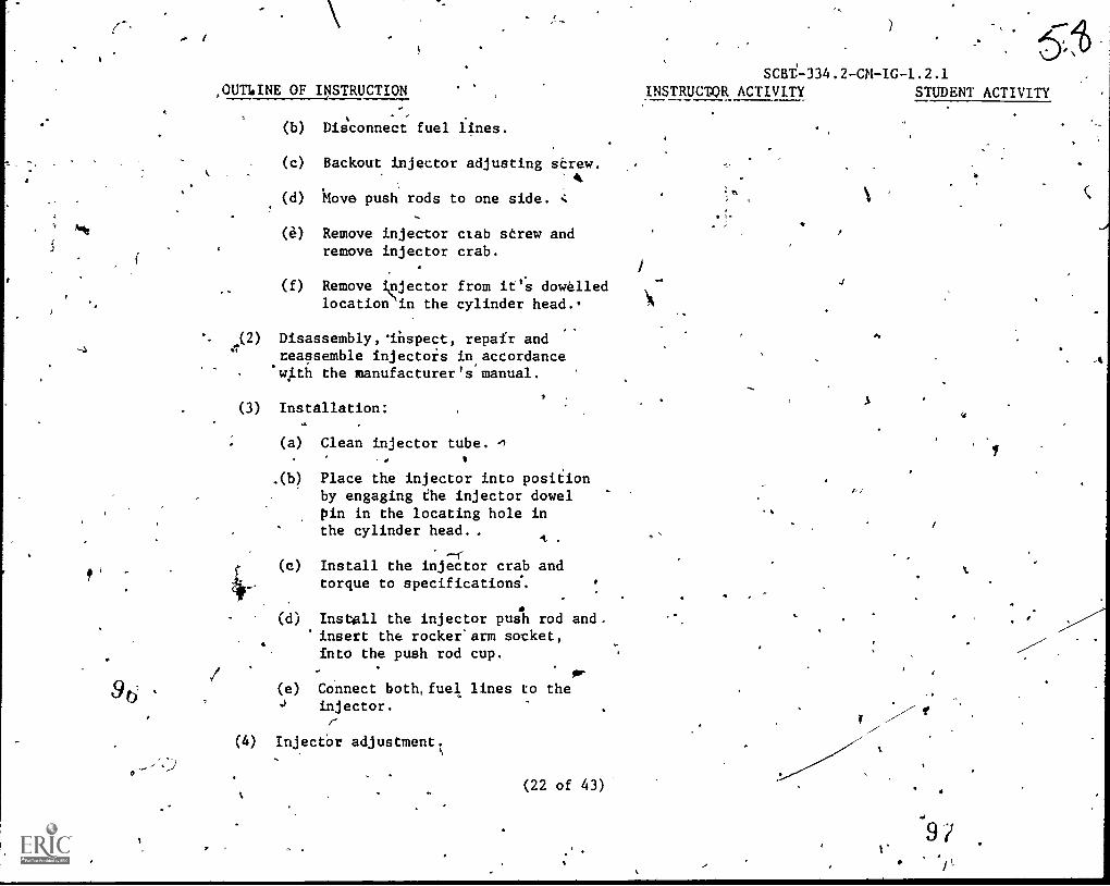
(b) DiE;connect fuel Iines.
(c) Backout injector adjusting strew.
(d) 'Move push rods to one side. s.
(a) Remove injector ctab strew andremove injector crab.
(f) Remove injector from it's dowelledlocatioein the cylinder head.,
4(2) Disassembly,Ihspect, repafr andneassemble injectors in accordancewj.th the manufacturer'simanual.
(3) Installation:
(a) Clean injector tube. .1
.(b) Place the injector into positionby engaging ehe injector dowelpin in the locating hole inthe cylinder head. .
(e) Install the injector crab andtorque to specifications%
(d) Insball the injector puEl rod and.insert the rocker'arm socket,Into the push rod cup.
(e) Connect both,fuel lines to theinjector.
(4) Injector adjustment
(22 of 43)
. '
INSTRUCTOR ACTIVITY STUDENT ACTIVITY
one 4
9 '7. .

4.
OUTLINE OF INSTRU CTIONSCBT-334.2-CM-1G-1.2.1-
, INSTRUCTOR ACTIVITY STUD'ENT ACTIVITY
2(a) 'Tighten adjusting screw until '
' the plunger jiist-bottoms. 4 (
(b) Loosen the adjusting screw 1/2turn.
(
ie.', (c) Use an inch/pound torque wrenCh., (4)(c) Tgke class to ghop and (4)(0, Observe demon
and socket adapter D1280,'tighten demonstrate nozzle and injector stration and followadjus,ting screw to 35 inch/pounds service. .1---,
.job sheet procedures.
cold setting.1
NOTE: .Injector adjustment muss be made priorto valve adjustment.
Roosi Master fuel inieétion.pump testing. /
The following tests are conducted with thepump mounted on an operating.engine. Kanetest equipment must be available.
r.
a. High-Agle adjustMent.
.(1) Disconnect throttle linkage.
(2) -Hold throttle level all the wayto the rear.
41-
(3) Adjust the high.idle stop screw 'until' the specified high idle speed isobtained.
b. Transfer puip'preisure.
(1) Install the compounegauge, assembly(tgol No. 4071) jn the pressure trapof the transfer pump.
(23 of 43)
,99

OUTLINE OF INSTRUCTION
(i) Operate engine at high idle.
(3) Record the reading zompare co menu-
/
facturer's specifications%
(4) If the reading is low remove thecompbund gauge assembly and installcompound gauge assembly in theinlet fitting of the transfer pump.
(5) Measure vacuum at inlet fitting oftransfer pump. Record and compareto, manufacturer's specificetions.
-7
NOTE: k4 the check shows the transfer pump andpressure regulating valve to be in aserviceable condition. Required supplypressure may be achieved by adjusting thepressure regulating valve.
c. Low idle.
Disconnect the linkage.
Move throttle lever of the pump forwarduntil engine speed drops to 500 to600 rpm.
(3) Turn idle screw in or out until lowidle speed is obtained.
(4) Lock screw in place.
d: Speed idvance operation (Model DC pumponly).
4
(24 of 43)
INSTRUCT6R ACTIVITY STUDENT ACTIVITY
4.

ouruNE OF INSTCTION
(1) Install the No. 13366 plastic timing
window.
(2) Align the following timing lines:
(a) Timing line on the'governorweight retainer aligni with the
cam timing-line.
(b) Timing marks an the vibrationAamper and the front case.
NOTE: If timing marks do not align, remove andreinstall the pump in accordance withmanufacturer's procedures.
(3) Start engine, run at fow idle andobserve the cath line, it.should not
move.
.(4) Increate engine speed.
NOTE: The cam should start to adVance somewherebetween 650 and 1,000 rpm. s.
(4) Record and compare with manufacturer'sspecifications.
(a) If the cam does not operate-properly, install the pressuregauge in the bottom of the end
plate.
SCBT-434.2-CM-IG-1.2,1
INSTRUCTOR ACTIVITY STUDENT ACTIVITY
, k
(2'of 43)
/

OCTLINE OF INSTRUCTION
(b) Turn the regulating valve springadjasting plug to obtain corxectPressure.
.e'(C) Pump housing pressure test.
1. Remove the pump timing platefrom the pump.
2. Install.the compoUnd pressuregauge, 4068 gauge block andthe 4077 flange, to the sideof the side of the Pump.
3. Operate engine at 6oth lowand high idle.
4. 6 to 8 PSI should bemaintained in' the pump.
Nozzle test.
' (1) Disconne.ct fuel line at nozzle.
(2) Connect Kiene test pump usirig connectornut 4014 and 4021 .Ermeto adapter tonozzle and connector nut'4012 to testpump.
(3) ....Seiect proper gauge for the test pump
in accordance with nozzle opening
pressure.
(4) Operate test pump and record openingpressure to nozzle.
4
-(26 of. 43)
INSTRUCTOR ACTIVITY STUDENT ACTIVITY
f:(4) Take classdemonstrate Roosapump service.
1,
to shop and*
Master fuel
11.
A
f.(4) Follow demon-.
stration whilereferring to job
sheet.
106
r
4
OUTLINE OF INSTRUCTIOd .
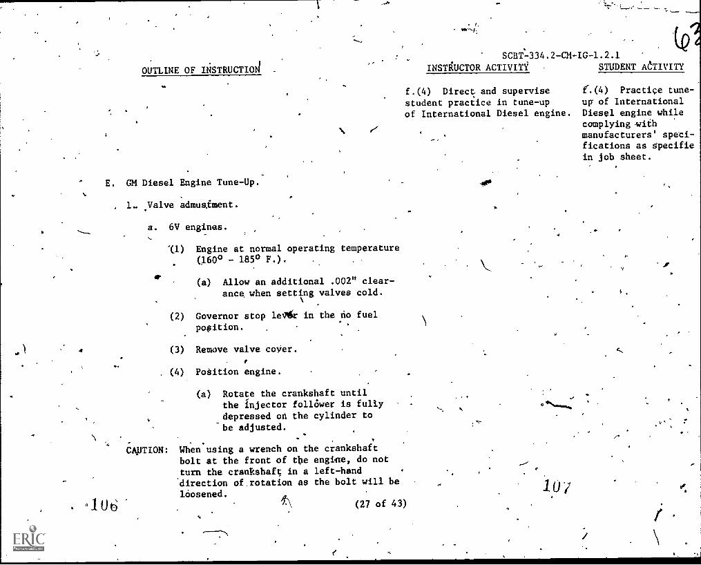
E. GM Diesel Engine Tune-Up.-
, 1. yalve admueEment.
a. 6V engines.
'(1) Engine at normal operating temperature(1600 - 185° F.).
et.(a) Allow an additional .002" clear-
ance when setting valves cold.
(2) Governor stop le/gc in the no fuel,
pooition.
(3) Remove valve coyer.
, (4), Pogition engine.
(a) Rotate the crankshaft untilthe injector follOwer is fullydepressed on the cylinder to
be adjusted.
CAPTION: When using a wrench on the crankshaftbolt at the front of the engine, do not
turn the crankshaft in a left-hand'direction of rotation as the bolt will be
loosened.
'I (27 of 43)
ff
(QeSCBTs-334.2-CM-IG-1.2.1
INSTAUCTOR ACTIVITi STUDENT AftIvITY
f.(4) Direct and supervise e.(4) Practice tune-
student practice in tune-up ug of International
of International Diesel engine. Diesel engine whilecomplying iihmanufacturers' sped--,fications as specifiein job sheet.
ir
f
(
OUTLINE OF INSTRUCTION
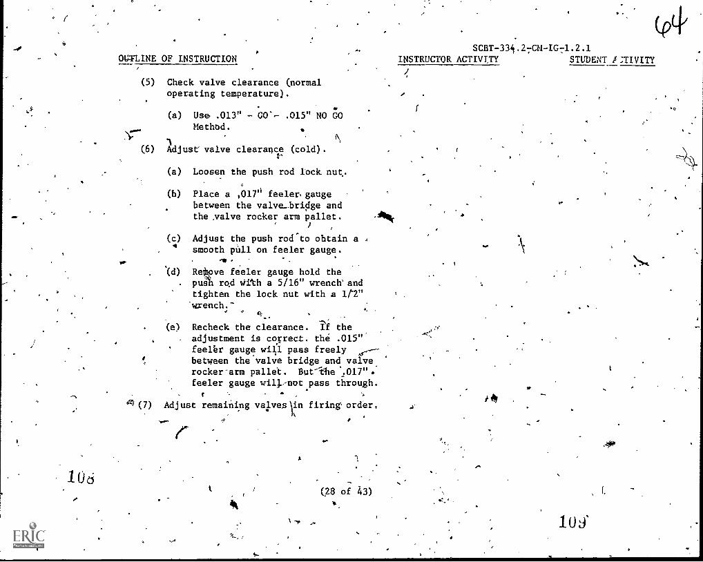
(5) Check valve clearance (normaloperating temperature).
(a) Use .013" - GO%- .015" NO GOMethod.
1(6) Adjust valve clearance (cold).
(a) Loosen the push rod Iock nut.
(b) Place a ,0176 feelen gaugebetween the valve_bri4e andthe valve rocker arm pallet.
(c) Adjust the push rocleto obtain a 4
smooth pull on feeler gauge.
'(d) ReitRve feeler gauge hold thepual rd With a 5/16" wrench' andtighten the lock nut with 2 1t2"
wrench.-/
(e) Recheck the clearance. if theadjustment is correct. the .015"feeler gauge will pass freely 0,--between the valve bridge and valverocker'arm pallet. But'ilte
feeler gauge will:not pass through.
g(7) Adjust remaining valvea\in firing order,
lUd -
(28 of 43)
1
SCBT-33i.27CM-IG71.2.1INSTRUCTOR ACTIVT,TY STUDENT 15:TIVITY
, f.
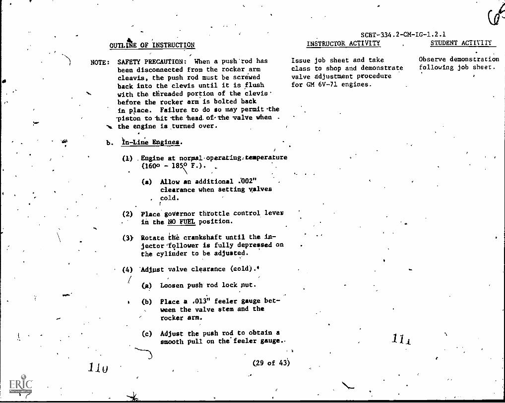
OUTLAE OF INSTRUCTION
NOTE: SAFETY PRECAUTION: When a push'rod hasbeen disconnected from the rocker ,armcleavis, the push rod must be screwedback into the clevis until it is flushwith the tfireaded portion of the clevis.before the rocker arm is bolted back
in place. Failure to do so may permitthe-piston to-hit-the fiesd.of-the valve when .
Ng. the engine isturned over.
b. In-Line Engines.
1Ly
(1) Engine at normal-operatingctemperature(1600 - 185° F.).
(a) Allow an additional :002"clearance when setting valvescold.
Place goVernor throttle control, lever
in the NO FUEL position.
Rotate the crankshaft until the in-jectorlollower is fully depressed onthe cylinder to be adjusted.
Aollust valve clearance (cold).4
(a) Loosen push rod lock nut.
(b) Place a .013" feeler gauge bet-ween the valve stem and therocker arm.
(c) Adjust the push rod to obtain asmooth pull on the'feeler gauge..
(29 of 43')
SCBT -334.2 -CM -IG -1.2.1
INSTRUCTOR ACTIVITY STUDENT ACTIVITY
Issue job sheet and take Observe demonstration
class to shop and demonstrate following job sheet.
valve ddjustmgnt procedure *
for GM 6V-71 engines.
11,

e
OUTLINE OF iNSTRUCTION
(d) Remove feeler gauge, hold thepush rod With'a 5/16" wrenchand tighten the lock hut with a
, 1/2" wrench.
(e) Recheck the clearance. If the
adjustment id correct the .011"feeler gauge will pass freelybetween valve stem and rockerirm, but the .013" feeler gaugewill not pass "trough.
(5) Adjust remaining valves in firing
order.
2. Injector timing.(In-Lin4 and 6V engine).
112
a. Use proper timing tool.
(1) 1.460", - for S-70 and 11V7 injectors
1.484" - HV6 injectors
b. Governor stop lever in NO FUEL position.
c. Position engine.
. (1) Valves fully open on cylinder to-be
i4justed.
d. Check timing dimensions.
(1) DiPtance from top of body to topof follower.
A
(2) Timing tao1,11 hole on top of body.%
(30 of 43)
SCBT-334.2-CM-IG-1.2.1
INSTRUCTOR ACTIVITic STUDENT ACTIVITY ,
4
1,23
11!
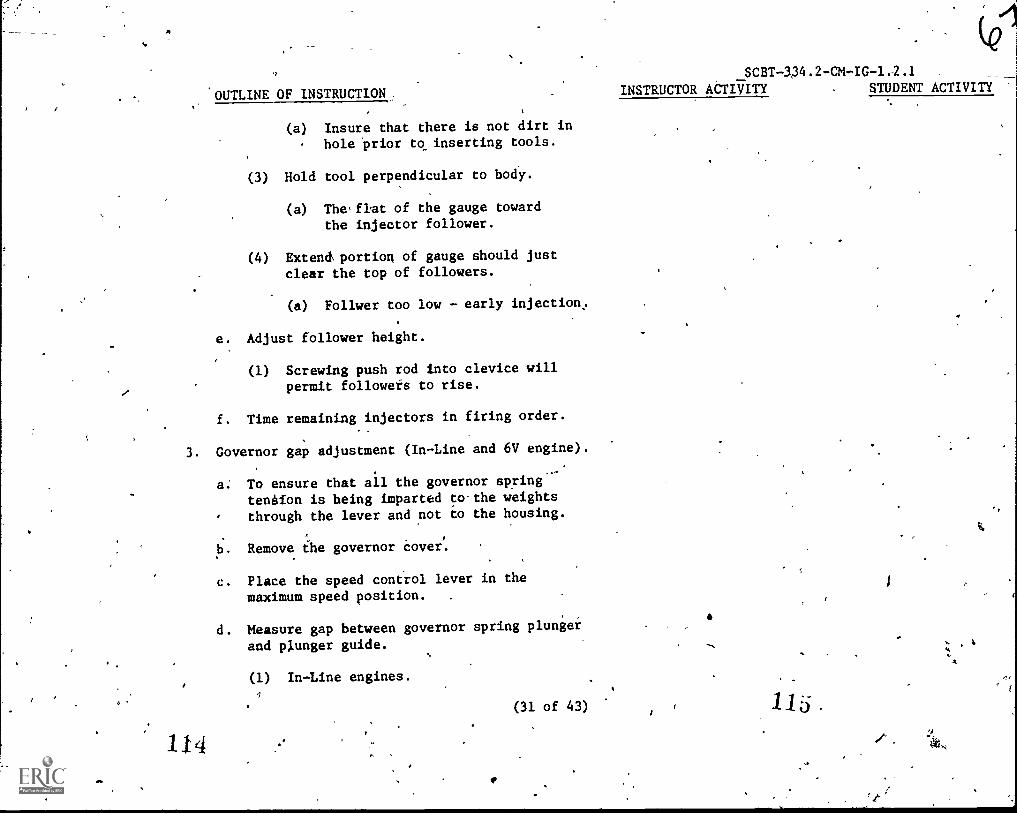
SCBT-334.2-CM-IG-1.2.1
'OUTLINE OF INSTRUCTION. INSTRUCTOR ACTIT/ITY STUDENT ACTIVITY
(a) Insure that there is not dirt in
hole 'prior tcrinserting tools.
(3) Hold tool perpendicular to body.
(a) The'flat of the gauge towardthe injector follower.
(4) Extenct portion of gauge should just
clear the top of followers.
(a) Follwer too low - early injection,.
e. Adjust follower height.
(1) Screwing push rod into clevice willpermit followers to rise.
f. Time remaining injectors in firing order.
3. Governor gap adjustment (In-Line and 6V engine).
114
a: To ensure that all the governor springteneion is being imparted to.the weightsthrough the lever and not to the housing.
b. Remove the governor Cover.
c. Place the speed control lever in themaximum speed position. .
d. Measure gap between governor spring plunger
and plunger guide.
(1) In-Line engines.
(31 of 43)
Ma.
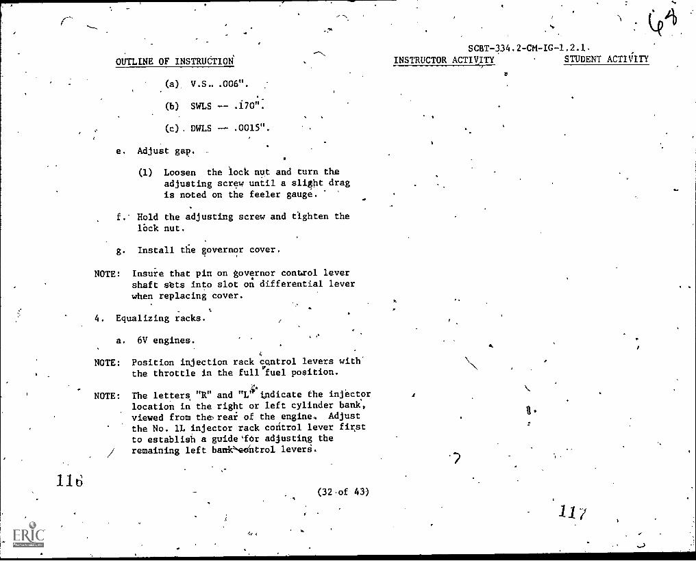
r-
OUTLINE OF INSTRUCTION'
.(a), V.S- .006".
(b) SWLS .170".
(c) . DWLS .0015".
e. AdjuSt gap.
(1) Loosen the iock nut and turn theadjusting screw until a slight dragis noted on the feeler gauge. "
f.' Hold the adjusting screw and tighten thelOck nut.
g. Install die governor cover.
NOTE: Insure that pin on governor control levershaft sets into slot on differential lever
when replacing cover.
4. Equalizing racks.
a. 6V engines.
4
NOTE: Position injection rack cantrol levers with'the throttle in the fullyfuel position.
NOTE: The letters "R" and "1,"1' tndicate the injector
location in the right or left cylinder bank,
viewed from the,reai of the engine. Adjust
the No. 1L injector rack control lever firstto establish a guidelor adjusting the
/ remaining left bank-\eentrol leverfi.
4+ 4,.
(32,of 43)
SCBT-334.2-CM-IG-1.2.1.
INSTRUCTOR ACTIVITY STUDENT ACTIiITY
lbw

>
OUTLIW OF INSTRUCTION .
1 r(1) Disconnect any\linkage attached to
the governor stop,lever.
(2) Loosen 'all of the inner and outerinjector rack control lever adjustingscrews on both cylinder heads and
both load limit device adjustingscrews.
NOTE: Be sure all injector rack control leversare "free" on the injector-control tubes.
11cs
(4) Check for binding in,the,governorto control tube linkage,by movingthe linkage through it's full rangeof travel with one,hand on the stoplever and the other hand on one of the
control'tube levers.
(5) Remove the clevis pin from the fuelrod at the right cylinder bank injectorcontrol tube lever.
(6) Move the speed control lever to theMAXIMUM SPEED position.
(7) Move the governor stop lever to the"RUN" position and hold it in that
position with light,finger pressure.
(8) Turn the inner adjusting screw of theNo. 1L injector rack control leverdown until a slight movement in thegovernor,stop lever is noted.
(33 of 43)
af;
SCBT -334.2 -CM -IG -1.2.1
INSTRUCTOR ACTIVITY STUDENT ACTIVITY

1.2 u
SCBT-334.2-CM-IG-1.2.1
OUTL/NE OF INSTRUCTION INSTRUCTOR ACTIVITY 7 . §TUDENT ACTIVITY
(9) Screw outer screw in until it bottomslightly on the injector control tube.
(a) Tighten inner and outer screwsalternately.
(10) Move the governor stop lever back endforth a few times and mote a "rotating"movement of the injector control fackwhen the stop leNcer is moved to the
"RUN" position.
(11) Hold the stop lever in the "RUN"position and using a screw driverpress downward op the injector controlrack.
(a) Rack should tilt.downward andwhen the pressure of the screwdriver is released, the controlrack should "spring" back upward.
(b) Adjust the Inner and outer adjustingscrews to obtain this condition.
(c) 'At this point, No. 1L injectorr4ck control lever is fullyadjusted.
(d) Tighten both the inner andouter adjusting screws andrecheck adjustment.
(12)' kemove'clevis pin from fuel rod-tit
the right cylinder bank injectorcontrol tube lever.
(34 ot 43)
121:

40
OUTLINE OF INSTRUCTION
Insert the cleyia pin.(13)the fuel rod
on the right cylinder hank injp.tor
control tube lever.'
(a) Adjust No. 1R injector 4ck the.same way you adjusted No. 1L.
(14T Adjust the remaining injector,Tacls,
control levers.
(a) Remove.clevis pin from the fuel
rods and the injector controltube levers.
Hold injector control racksin the full-fuel position.
(c) Turn,down the inner adjusting /screw of the injector packcontrol lever until the screwbottoms (injector control rack
in thesfull-fuel position).
(0) Turn'down outer adjusting screw othe injector rack control leveryntil it bottoms on the injector
4control tube.
°CO- still holding control tube-
lever in`the full-fuel position.Adjust the inner and outeradjusting-screws to obtain the
same condition as outlined in
c step (11).
4
SCBT-334.2-CM-IG-1.2.1
'$ INSTRUCTOR ACTIVITY TENT ACTIVITY
,
1.
14411
r
12j

SCBT-334.2 -CM
OUTLINE OF INSTRUCTION 4 INSTRUCTOR ACTIVITY STPDENT ACTIVITY
CAUTION: Once No. 1L and No. 1R injector rackcontrol levers are adjusted do nottry to alter their settings.
(15) When all injector rack control leversare adjusted recheck their settings.
(16) Insert the clevis pin in the fuelrods and the injector control tub&levers.
,b. In-Line engines.
(1) Disconnect any linkage attached tothe governor, stop lever.
(2) Back out the buffer screw 5/8"...
(3) Loosen all of the inner and outerinjector rack control lever adjustingscrews.
4
NOTE: Be sure all injector rack control levers'are "f'ree" on the injector control tubes:
(4) Move spded control lever to MAXIMUM-SPEED position.
(5)
a.(15) Take class to shop anddemonstrate injector timingand rack equalization proc-edures.
Move the goVernor stdp lever to the"Run" position and hold it that position
with'Itght-finger-pressme.
(6) Turn the inner adjusting screw ofthe No. 1 injector rack control lever
. down until a slfght,movement in thegovernor stop lever is'note4.
(36 of 43)
4
a.(15) Observe demon-stration and followprocedures outlinedin job sheets.

OUTLINE OF INSTRUCTION
/1(7) Screw-outer screw in Aintil it
bottoms lightly on the injector
control tube.
(a) Tighten inner and outer screws
alternately.
(8) MOve the governor stop lever back and
forth a fe4 times and note a "rotating"movement of the injector control rackwhen the stop lever is moved to the
"Run" position.
Hold the-stop lever,in the "Run"position and using a screw driverpreds downward on the injector
control ra4k.
(9)4
(a) Rack should tilt downward and whenthe pressure of the screw driver isreleased, the control rack should
"spring" back.upward.
(b) Adjust the inner and outer adjustingscrews to obtain this condition.
(4 At this point, No. 1 injector rackcontrol lever,is fully adjusted.
(d) Tighten both the timer and outeradjusting screws and recheck
adjustment.
IA.,.
(10) Adjust'the remaining injector rack
control levers.
-;
(37 of 43)'
SCBT-334.2-CM-IG-1.2.1
INSTRUCTOR AtTIVITY STUDENT ACTIVITY
,e
A,
.5
1 2

26
OUTLINE OF INSTRUCTION
(a) Remove clevis pin from the fuelrods and the 4njector controltubelevers.
(b) Hold injector control racks inthe full.--fuel position.
(c) Turn down the inner adjustingscrew of the No. 2 injectorrack control lever until thescrew bottoms (injector controlrack in the full-fuel position).
(d) Turn down outer adjusting screwof the injector rack controllever until it bottoms on theihfector control-tube:-
1f (e) Male still holding control tubelever in the full-fuel position.Adjust.the inner and outeradjusting screws to obtain thesame condition as outlined instep (9).
CAUTION: Once No. 1.injector rack Control lever ,
is adjusted do not try to alter thissetting.,
,(11) When all Injector radk ccintrol 'leversare adjusted recheck their settings.
(12) Insevt,the clevis pin in the fuel rodand the injector control tube lever.
(38 of 43)
SCBT-334.2-CM-IG-1.2.1INSTRUCTOR ACTIVITY STUDENT ACTIVITY
1 23
Lid

OUTLINE OF INSTRUCTION
S. Idle and buffer spring adjustment.
a. Start engine and run until warm.
(1) Stop lever in run position.
SCBT-334.2-CM-IG-1.2.1
INSTRUCTOR ACTIVITY . STUDENT ACTrVITY
(2) Speed tontrol lever in idle position.
b. Adjust idle speed screw.
(1) Loosen lock nut and turn idle speed
screw until engine idles atrecoMmended idle speed.
c. Adjust buffer screw.
(1) Engine at idle speed
(2) Turn huffer screw "IN" so that it
contacts differential lever as
lightly as possible and stilleliminates tengine roll.
(3) Hold buffer screw and .tighten
lock nut.
NOTE: Do riot raise engine idle speed more
than 15 rpm with the buffer,screw.
6. Load limit device adjustment (6V engines).
a. Mechauically'limits the travel Of the
injector racks and thereby the fuel
output of the injectors.
-The load limiting,device isadjusted after
the engine tune-up is coMPletea.
130 (39 of 43),
13.1:

OUTLINE OF INSTRUCTION
(1) Loosen load libit screw lock nut:
(2) Back load limit screw out of theadjustiniscrew plate until 1"of the screw is below plate.
(3) Adjust load linit lever clamp bolts
so the lever is free to turn on the
injector tack control tube.
(4) Loosen load limit lever clamp bolts
so the lever is free to turn on the
injector rack control,tube.4
(5) Thread the load limit screw into the
adjusting screw plate until thelock nut "bottoms" against the top
of the plate.
(6) Hold injector rack control tube in
the full-fuel position and place
the load limit lever, againstthe bottom of the load limit screw.
Then tighten the load limit lever
clamp bolts.
SCBT-334.2-CM-IG-1.2.1
INSTRUCTOR ACTIVITY STUDENT ACTIVITY
(7) Check to ensure that the injector b.(7) Take class to shop 'and b.(7), Observe demon-
.
racks will jus.t go into the full- \ demonstrate load limit adjust- gtration and foli-ow,
fuel position. ment, job sheet procedures.
(8) Hold load limit screw to keep it from
turning, then set the,lock nut until
the distance between the bottom of
the lock nut and top of the adjusting,
screw plate.
(40 of 43)
vo,
133

OUTLINE OF*INSTRUCTION
(a) Corresponds to the Marking onthe adjusting screw,plate.
(9) Thread load limit screw into theplate until the lock nut "bottoms"againdt the top.of the plate.
(10) Hold load limit screw to keep it fromturning, then tighten the lock nut"
to secure the setting;
7. Fuel flow test.
134
a. Disconnect-return line to tank.
b. Operate engine at 1,200 rpm and measureamount of fuel flow intd a container for
one -minUte.
(1) 0.8'gallong of fuel per minute(6V engine).
(2) 0.5 gallon 'of fuel per minute (In-Line engine).
c. Immerse tube in fuel and watch for air
bubbles.
(1) Indicates leakage on sdction side
of pump:
(a) Filters, gaskets and lines.
(41 of, 43)
SCBT-334.2-C1-IG-1.2.1
INSTRUCTOR'ACTIVITY STUDENT ACTIVITY
Redemonstrite any proceduresnot cOmpletely clear to class
using student assistancewhere needed.
Observe demonstratic
following steps out .
lined in job,.sheet
Parti;ipatinxin prc(Me.* .as called on 1
InVauctor..

4
OUTLINE OF INSTRUCT/N
Application:
tt,
I..
A. Studenls p4rform diesel engine tune-up to restoreengine perfOrmance to manufacturer's specificationsusing approPriate tools and'procedures specifie"dby the manufacturees-as stated id' the job sheet'
Without deviations
- IV. \Summary:
A. Aneral'checks.
B. Caterpillar engine tune-up procedures.
C. Cummins engl,ne tune-up procedures:4
D. Internation engne tupe-up procedures.
E. General motors engine tune-up procedures.
136
N
(42 of 43)
SCBT-334./-CM-IG-1.2.1_ INSTRUCTORACTIVITY
,Direct/and supervise, studentpractice in tune-up of GM6V-71 diesel englne.
III. Direct, supervfk andevaluate student performancepin conducting diesel engine
Air
STUDENT ACTIVITY.
Practice tunepup of-71 diesel engines
while pomplyini withmanufacturer's spec-.ifications as outlinein the job sheet"
III. Tune-up diesel
engines using approp-riete tools and proce-ures as specuica
by the manufacturer's 7--
, without'deviation is stated
in the job sheet.
137 C.

V. Test:
or)
OUTLINE OF:INSTRUCTION '
A. Knowledge given in this topic will be graded onthe basis/of a written test student must anaer35 of 50-test items correctly.
B. Student will be examined 4h the practical aspectsof_this tOpic by tuning diesel engines to complywith manufacturer's specifications withoutdeviation.
VI: Assignment: Wine. .
"4ot
7 7.
INSTRUCTOR ACTIVITY 'STUDENT ACTIVI
V. Administer test. V. Take,test asdirected by instr
V.A.-Correct tests and eval- V.A. Participateuate results. Review missed class discussiontest item with class missed test items
(43 of 43)

SCST-334.2-CM-JS-1..2.1.1
NAVAL CONSTRUCTION TRAINING CENTERPORT HUENEME, CALIFORNIA 93043
SPECIAL CONSTRUCTION BATTALION TRAINING COURSE (SCBT) 334.2
JOB SHEET
TITLE: Diesel Engine Tune-Up,-Cummins with P.T. Fuel System
INTRODUCTION: The purpose of this job sheet is to guide You in thepractical performance of restoring engine performance of a Cumminsdiesel engine with P.T. Fuel System to a specific level as required,
by che manufacturer. Each ?student will use the required hand anA
special tools for making valve adjustments, setting injectors,and using specific maz equipment,to trouble-shoot a Cummins P.T.pump. Corrective adjustments will be,made in accordance with thejob sheet, the instructor will inspect procedures to determinejob errors, safety procedures and proper sequence of /les beforeproceding to the next procedure.
TOOLS AND EQUiPMENT:
1. Diesel engine shop hand tools.
2. Cleaning solvent.
3. Wiping rags.
4. Diesel fuel.
5.. Cummins special tools.
6. Torque wrench.
7. hickneSS-gauge.
CONDITIONS:
1. Each student will be-assigned t4 a Cummins engine to accomplish
test and Xune-!up procedures.
2. Each.student will be provided with all the required tools,
imanuals and job sheets.
3. ProCeeding the shop pecformance all aspects of the job withnecessary background data will be,covered in an actual shopdemonstration by the instructor.
(1 'qf 5)
1 4

i
SCBT-334.2-CM-JS.41.2.1.1
PROCEDURES:
1. General checks.
a. Remove and inspect air cleaner.
b. Inspect related air system piping.
c. InsPect turbocharger and manifold piping.
d. Check external fuel systeM components.
e. Check "V" belt drivers.
f. Check batteries.
STOP: Instructor,Check Point
g. Prestart check engine in preparation for starting engine.
h. Start engine and run until normal temperature is reached.Stop engine.
i. Remove hood if applicable.
j: Remove,valve cover.
k. Rotate engine until the first "VS" mark on the pulley ordamper is aligned with.the index mark on, the housing.
STOP: Instructor Check Point
1. Loosen lock nut on injector push rod.
m. Using a good torque wrench with screw driver adapter,draw the injector adjusting screw tight, then loosen.
n. Set the torque wrench dial to 48 inch/pounds and thentdrn.the screw tight until the torque wrench hand comesto zdro.
NOTE: This sequence should bs done in near continuous motion to'achieve_accurate adjustment of thd injector plunger,
o. Tighten lock nut:
STOP: Indtructor Check Point
NOTE: If the engine is equipped with a valve cross head, cross headadjustment must be made prior to valve adjustment.
(2 of 5) 1
4

4
SCBT -CH-JS -1.2.1.1%
p.- Loosen the adjusting screw lock nut and back off the
adjusting screw one turn.
q. Use light finger. Pressure at the rocker lever contactsurface with the valvi stem nearest the push rod.
0 r. Turn adjusting screw down until it contacts-it's mating ,
valve stem.
s. Hold the adjusting screw in this position and tighten lock
nut to specified torque.
STai---Instructor Chesk Point
t. Loosen rocker arm lock tult4.
u. Using d specified thickness gauge turn the'adjusting
screw to obtain a good contact on the thicknetis gauge.
v. Set both the intake and exhaust valves.
w. Tighten lock nuts.
x. Bar engine over in direction of rotation and firing order
and set the rest of the injectors, crossheads and valves.
STOP: rnstructor Check Point
y. Install valve covers.
z. Remove fuel pump filter screens.
aa. 4lean screena.
bb. Reinstall and torque to specified limits.
cc. Attach tachometer to the drive outlet on top of the-
fuel pump.
dd. Remove pipe plug from spring pack cover.
ee. Set engine idle to manufacturer's specifications.
ff. Replace pipe plug.
NOTE: Engine idle speed changes when the housing fills with fuel.
STOP: Intructor Check Point
(3 'of 5)
'0
142
p.

SCBT-334.2-CM-JS-1.2.1.1
gg. Check high idle using tachometer connected te the driveoutlet.on top of the fuel pumps..
NOTE:. If high idle has to be changed, shims will either have to beadded or removed from beneat the governor high-speed spring andthe high-speed spring retain
hh. Shut engine down.,
ii. Remove 1/8" pipe plug from the side of the fuel shut-offvalve.
jj. Install ST-435 pressure gauge.
STOP: Instructor Check Point
kk. Btart engine.
11. Snap the throttle fully open two or three times and carefullywatch the gauge.
400'
mm. Screw xear screw outward until firessure increase stops:
nn. Turn screw inward until pressure drops 3 to 5 PSI.
STOP: Instructor Check Point
oo. Lock screw in place.
-NOTE: Refer to specification sheet for the engine model. Keep in mindthat snap fuel pressure readings are 3 to 5 PSI higher than asteady reading would be under load.
pp. Run engine a#idle speed.
qq. Screw forward throttle screw inward until engine beginskgaining speed.
rr. Back out screw two turns and lock.
sp. Remove spriag iavk cover plug and adjust governor screw.
(1) 5 -10 RPM below idle speed.
tt. Replace plug and run engine Until all air is purged from.system.
iTOP: InstrUctor Check Point
uu. Install'ST-435 gauge at the shutToff valve.
vv. Operate engine 400 RPM below governor speed.
(4 of 5)
143

SCBT -334.2 -CM-JS
ww. Accererute Go governed speed.
(1) Observe gauge for specified pressure.
(2) Maximum pressure is adjusted by removing or'installingshims in pressure regulating,valve.
STOP: Initructor Check Point
xx. Install the ST-435 vacuum gauge at gear plZip inlet.
yy. Operate engine for 5 minutes to purge air from syStem.
zz. Observe gauge reading, should not exceed 8 to 8.5" macuum.
STOP: Instructor Check Point
AA. Shut doWn engine.
BB. Install sight gauge on pumps inlet side and operate engine.
CC. Check for air bubbles.
4

SCBT-334.2-CM-JS-1.2.1.2
NAVAL CONSTRUCTION TRAINING CENTERPORT, HUENEME, CALIFORNIA 93043
SPECIAL CONSTRUCTION BATTALION TRAINING COURSE (SCBT) 334.2
JOB SHEET
4, TITLE: Diesel Engine Tune-UpInternItional with Roosa Master,Fuel Systet
Nowi
INTRODUCTION: The purpose,of this job sheet is to guide you in thepractical performance of restoring engine performance of aInternational Diesel Engine with Roosa Master Fuel Injection Pump
ley or: VI -
,will use the required hand and special tool's for making valve adjust-ments, setting injectors or replacing nozzles if required by theinstructor. Install tpecific test equipment, record and analyzereadings, and make corrective adjustments as required bh thejob sheet and.the manufacturer's manual. At designated points onthe job sheet, the instructor will inspect procedures to aeterminejob errors, safety procedure and proper sequence of events beforeproceeding to the next procedure.
TOOLS AND EQUIPMENT:
1. Diesel engine shop hand tools.
tat2. Cleaning solvent..
3. Wiping rags.
4. Diesel fuel.
5. International and Roota Master special tools.
6. Torque wrench.
7. Thickness guages.
CONDITIONS:
1. Each student will be assigned to an International engine withRoosa Master Fuel Systdm to accomplish test and tune-upprocedures.
.Each student-will be'provided with all required tools, manualsand Sob sheets.
3. Preceeding the shop performance all aspects of the Jbb withnecessary background data will be covered in an actual shopdemonstration by the instructor.
(1 of 5)

SCBT-334.2-CM-JS-1.2.1.2
PROCEDURES:
1. General checks.
a. Remove and inspect air cleaner.
b. Inspect related air system piping.
c. Inspect turbocharger and manifold piping.
d. Check external fuel system components.
e. Check V belt drivers.
f. Check batteries.
STOP: Instructor Check Point.
g. Prestart check engine in preparation for starting.
h. Start engine and run until normal temperature is reached.Stop engine.
i. Remove hood if applicable.
j. Remove valve cover.
k. Rotate crankshaft until number one (1) piston is on thecompression stroke.
NOTE: The timing pointer on the front cover will be in line with T.D.C.Mark on the vibration damper.
STOP: Instructor Check Point
1. -Loosen rocker arm lock nuts.
m. Use a feeler gauge of a specified,thickness and turn therocker arm adjusting screw in or'out, until the correctfeeler gauge'clearance is obtained.
n. Set both intake and'exhaust valves.
NOTE: If the' engine is equipped with nozzles, prodeed to the next cylinder.'If the engine is equiliped, with injectors, injector setting should 'be made prior to valve adjustment (injector setting).
(2 Of 5)
146

SCBT -334.2 -CM-JS -1.2.1.2
o. Tighten adjusting screw until the plunger just bottoms.
p.
q.
Loosen the adjusting screw 1/2 turn.
Use:an inch/pound torque wrench and socket adapter D-1280
and tighten the adjusting screy -to 35 inch/pounds cold
setting.
STOP: Instructor Check,Point
r. Install valve covers.
s. Disconnect throttle linkage.
't
t. Using a tachometer, adjust the high idle stop screw until
the specified high idle speed is obtained.
u. Shut down engine.
v. Install the compound gauge assembly (tool no. 407) in'the pressure.trap of ,the transfer pump.-
STOP: Instructor Check Point
w. '-.0perate engine at high idle.
x. Record the reading and compare to manufacturer's speci7
fications.P
STOP: InstActor Check Point'
y. Remove the compound gauge assembly.
z. Install the compound gauge apsembly in the inlet, fitting
of the transfer pump.
STOP: Instructor Check Point 11
aa. Operate engine at high idle:
bb. Record the reading and compare to'manufacturer's speci-
fications.
NOTE: -If the-checks_shows the transfer pumps and pressure regulating
valve to be in a serviceable condition. Required supply pressure
may be achieved by adjusting the pressure regulating valve.
STOP: Instructor Check Point
(3 of 5)"
1 4:/

"cc. Remove compound pressure gauge...
SCBT-334.2-CM-JS-1.2.1.2
_.)
dd. Use a eackometer and screw the low idle screw either in orout to obtain a low,idle speed of 500 to 600 RPM.,
ee. Stop engine.
NOTE: If engine is e'quipPed with a model D.C.operation has to be checked.
pumps, speed advance:to
ft. Install the'plastic timing window No. 13366 on the punap.
gg.
t.
a
,.
Align the following timing marks.
(1) Timing.line-on the governor weight retainer .71.th'the'cam timihg line.
(2) Alignment of the timing marks ontthe vibration damperand the front case.
STOP: Instructor Check Point
NOTE: If the timing marks (16 not.afign remove and reinstall the pumpin accordance with manufacturer's proceduies.
hh. Start engine and observe the cam line from idle to highidle. Observe and record number of degrees of cam move-ment.
,
STOP: Instructor Check Point
. NOTE: If the cam does not-Operate properly install the pressure gaugein the bottom of the end plate.. .
Turn the regulating,valve spAag'adjusting'plug to obtainthe cqrrect ptessure as specified by the manufacturers
STOP: Instructor Check Point
Remove the pumps timing plate from the pumps.
Install, the-compound pressure-gauge, 4068-gaugeand the 4072 and 4077 flange to the side of the pump.
11. Qperate the engine at both:low and high idle.
mm. Record the reading.and compare to panufacturer'S sjeci-fications,
(4 ot. 5)
148
:

STOP: Instructor Check Point
,
, ....
nn. bisconnect Tuel line at the nozzle.:. :-> ,
r ',
t ,
. 00. 'Connect Kiene test pump using connector nut 4014 and 4021
Ermeto Adapter to nozzle and connector nut 1012 to test
pumps.1 ,
1.
pp. Select proper gauge .for the test pump in accordance witiC
nozzle opening pressure.
STOP: Instructor Check Point'
1*
ql.Operke pump end recvd opening pressure of
7w nozzle. _0 , ,
,
NOTE:trFr90 the privious tests and analyzing the resulis, troubles'in.-
/ itfi4 Roosa Master Fuel System can be pin-pointed and,repairid
in a short perlod of time., - A.
4 Li..:::t 1 :.'
A
Y'
71 .
(5 of 5).
: 4
N.

-4 SCBT -334.2 -CM-JS -1.2.1.3go
NAVAL CONSTRUCTION TRAINING CENTER
PORT HUENEME, CALWORNIA 93043SPECIAL CONSTRUCTION BATTALION TRAINING aOURSE (SCBT) 334..2
TITLE: Diesel Engine Tune-Up; GM In-Line and V6-71
JOB SHEET
....-iliTRODUCTION: The purpose of this job sheet is to guide you in the
practicallierformance of restoring engine performance of a GM
Dien). Engine to specific level as required by the manufacturer.
EachIstudent will use the required hand and special tools for making
valve adjustmepts, injeceei timing, rack equalization and replace-
ment of specified.components, followin&procedures given in this
aob sheet and complying with manufacturer's specifications without
deviation at de ignated points in the job sheet, the instructor
will inspec,4?t 'rocedures to determine job errors, safety procedures
. and proper sequence of events before proceeding to the next proce-
dure. .
./
TOOLS 'AND EQUIPMENT:
1. Diesel engine shop hand tools..
2. Cleaning solvent.
3. Wiping ra$s..
4. Diesel fuel. 000,00%10m.
,5. GM diesel special tune up tools.
6. Torque wrench.
7. Thickness gauge.
CONDiTIONS:
1. Each student will be assigned to various qm Diesel Engines to
acgamplish test and tune-up procedures.
2. Each student will be provided withFall the required tools, manuals4
and job.sheets.
Preceding the shop performance all aspects of the job with
mecessary,background data will be covered in actual shop
demohstrations,by the instructor.
(1 of 5)

SCBT-334.2-CM-JS-1.2.1.3
PROCEDURES:
1. GM V6-7I Diesel Engine,Tune-Up.
a. Prestirt check engine, start and bring engine temlidilatureup to, operating ringe.
b. Remove valve cover.
c. Rotate crankshaft until the injector follower is fully,depressed on the cylinder to be adjusted.
NOTE: When using a wrench in the crankshaft bolt on the front of theengine, do not turn the crankshaft im a LEFT hand direction ofrotation as the bolt will be loosened.
d? Loosen push rod lo.ck nut.
e, Insert a feeler gauge of a predetermined thickness betweenthe rocker armsand the end of the valve.
NOTE: If equipped with a valve bridge, insert feeler gauge between the.rocker arm and the valve bridge.
f. Rotate the engine in the direction of travel and set theremaining valves in'accordance with the firing order.
STOP: Instructor Check Point
g. Ro.tate engine until the exhaust valves on a specifiedcylinder are fully open.
h. Using.the proper timing tool.
(1) 1.460 for S-70 and HV-7 injection.
12) 1.484 for HV-6 injector.
i. Insert timing tool in hole on top of the injectorJr:body.
AI
j. Wd the tool perpendicular to body, slowly rotate thetools so the extended portion of the gauge just clears thetop of the follower.
k. Time the remaining injectors in firing order.
STOP: Instructor Check Point
(2 of 5)
c 15i

SCBT-334.2-M-J.S-1.2.1.3
1. Remove the gorernor cover.
m. Place the speed control lever ia the maximum speed
position.
_ .
n. Measure the gap between governor spring plunger and
plunger guide.
o: Set to manufacturer's specifications
STOP: Instructor Check Point
p. Install the governor cover.
) NOTE: Position injection rack control levers with the throttle in the
full-fuel position.
)OTE: ,The letters "R" and "L" indicate injectorlocations in the
RIGHT or LEFT gylinder bank, viewed from the rear of the engine.
Adjust the No. 1L injector rack control leiter first.
q Disconnect any linkage attached to governor
r. Back out buffer screw 5/8".
stop lever.
84 Loosen all of the inner and Outer injector rack control
lever adjusting screws on both cYlinder heads and both load,
'limiting device adjusting screws.
NOTE:, Be sure all injector rack control levers are free on the injectorf
tubes.
STOP: Instructor Check Point
t. Remove the clevis pin from the fuel rod at the RIGHT
cylinder bank injedtor control tube lever.
u. Move the.speed controrIever to the maximum lyeed
position.( )
v. Move the governor stop fever to the "RUN" Position and hold
it in that position with light finger 'pressure.
w., Turn,the inner adjusting shrew of No. 1L injector rack
control lever down until a slight movement in the governor
stop lever is noted.
16,
(3 of )
152
fta.
SCET-334.2-CM-JS-1.2.1.3-
x. Screw the outer screw "IN" until it bottoms lightly'onthe injector controlltube.
(1) Tighten inner and outer screws alternately.
y. "'I:14d the stop liver in the "RUN" position and using ascraw driver presidownward on the injector cpntrol rack.Ra%.*-. should tilt downward, release screw drivr pressure,the control rack should spring backward.
STOP: Instructor Check Point
z. Adjust the raiaining racks on:. the left bank&
aa. Remove Ihe clevis pininjector control tube
bb. Insert the clevis pinbank injector control
STOP: Instructor Check Point
from the fuel rod at the LEFT banklever.
in the fuel rod on the RIGHT cylindertube lever.
Adjust the RIGHTSIDE in the same manner as the LEFiSIDE,use steps v to.aa.
NOTE: The procedure for equalizing racks onidentical to equalizing one bank on a
dd. Reconnect all linkage.
STOP: Instructor Check Point
in-line'engines is"V" type engine.
ee. Start and4operate engine until warm.
ff. Loosen lock nut and turn idle speed screw until engineidles at recommended idle speed.
gg. Hold idle speed screw and tighten lock nut.
hh. Turn buffer screw IN so that it contacts the differentiallever as lightly as possible and still eliminates engineroll.
Hold,buffer screw and tighten lock nut.
NOTE: Do not raise engine idle speed more than 15 RPM with the bufferscrew.
STOP: Instructor Check Point
(4 of 5)'

ii
SCBT-334.2-CM-JS-1.2.1.3
If equipped with a load limiter, loosen load limit &crew
lock nut.
kk. Adjust load limit screw lock nut so the bottom of thelock nut is 1-3/4" from the bottom,of the load limit.
screw. .
II. Tighten lock nuts.
mm. Disconnect return- fuel line to tank.
nn. Operate engine at 1,200 RA and measure amount Of fuel intoa container for one minute. Oompsre.to manufactureeispecifications.-
es
f
1
(5 of 5)-
.(
, 6,