T-A - Allied Maxcut® Accessories T-ACR45™ Chamfer Ring ... 2T-5SRM 44.45 76.20 34.92 M10 1/4" ......
24
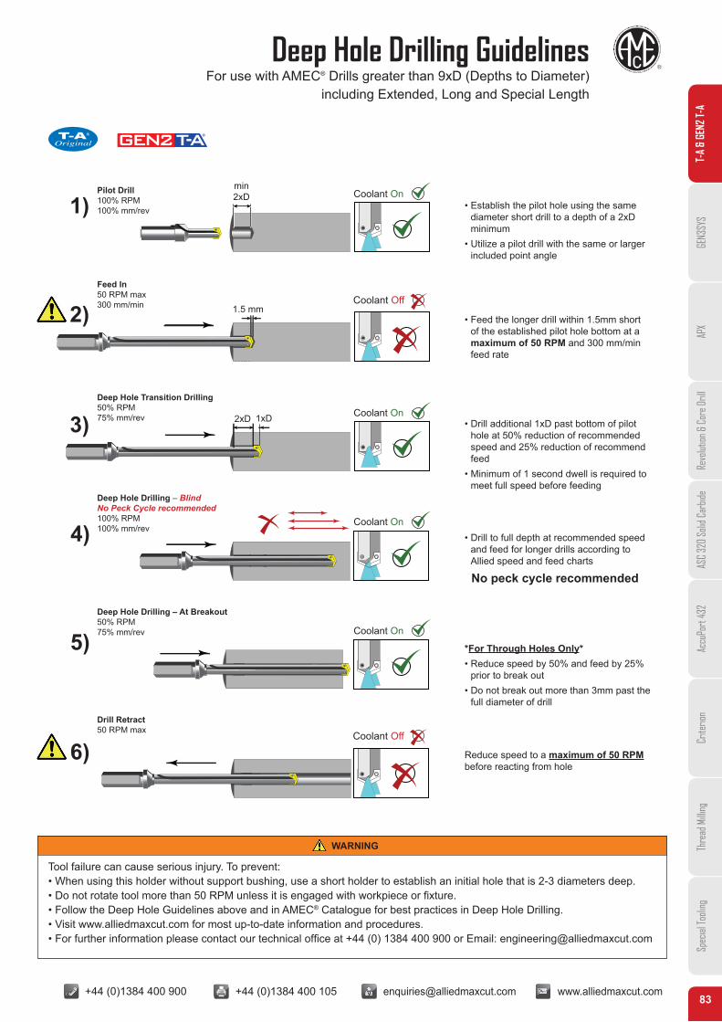
+44 (0)1384 400 900 +44 (0)1384 400 105 [email protected] www.alliedmaxcut.com 83 Deep Hole Drilling Guidelines For use with AMEC ® Drills greater than 9xD (Depths to Diameter) including Extended, Long and Special Length T-A & GEN2 T-A GEN3SYS APX Revolution & Core Drill ASC 320 Solid Carbide AccuPort 432 Criterion Thread Milling Special Tooling T-A ® Original min 2xD 1) 2) 1.5 mm 1xD 2xD 3) 4) 5) 6) Coolant On Coolant On Coolant On Coolant On Coolant Off Coolant Off Pilot Drill 100% RPM 100% mm/rev Feed In 50 RPM max 300 mm/min Deep Hole Transition Drilling 50% RPM 75% mm/rev Deep Hole Drilling – Blind No Peck Cycle recommended 100% RPM 100% mm/rev Deep Hole Drilling – At Breakout 50% RPM 75% mm/rev Drill Retract 50 RPM max Tool failure can cause serious injury. To prevent: • When using this holder without support bushing, use a short holder to establish an initial hole that is 2-3 diameters deep. • Do not rotate tool more than 50 RPM unless it is engaged with workpiece or fixture. • Follow the Deep Hole Guidelines above and in AMEC ® Catalogue for best practices in Deep Hole Drilling. • Visit www.alliedmaxcut.com for most up-to-date information and procedures. • For further information please contact our technical office at +44 (0) 1384 400 900 or Email: [email protected] WARNING • Establish the pilot hole using the same diameter short drill to a depth of a 2xD minimum • Utilize a pilot drill with the same or larger included point angle • Feed the longer drill within 1.5mm short of the established pilot hole bottom at a maximum of 50 RPM and 300 mm/min feed rate • Drill additional 1xD past bottom of pilot hole at 50% reduction of recommended speed and 25% reduction of recommend feed • Minimum of 1 second dwell is required to meet full speed before feeding • Drill to full depth at recommended speed and feed for longer drills according to Allied speed and feed charts No peck cycle recommended *For Through Holes Only* • Reduce speed by 50% and feed by 25% prior to break out • Do not break out more than 3mm past the full diameter of drill Reduce speed to a maximum of 50 RPM before reacting from hole
Transcript of T-A - Allied Maxcut® Accessories T-ACR45™ Chamfer Ring ... 2T-5SRM 44.45 76.20 34.92 M10 1/4" ......
+44 (0)1384 400 900 +44 (0)1384 400 105 [email protected] www.alliedmaxcut.com +44 (0)1384 400 900 +44 (0)1384 400 105 [email protected] www.alliedmaxcut.com83
Deep Hole Drilling GuidelinesFor use with AMEC® Drills greater than 9xD (Depths to Diameter)
including Extended, Long and Special Length
T-A
& GE
N2 T-
AGE
N3SY
SAP
XRe
volut
ion &
Cor
e Dril
lAS
C 32
0 So
lid C
arbid
eAc
cuPo
rt 43
2Cr
iterio
nTh
read
Milli
ngSp
ecial
Tooli
ng
AMEC
T-A®
Original
min 2xD1)
min
2) 1.5 mm
1xD2xD 3)
4)
5)
6)
Coolant On
Coolant On
Coolant On
Coolant On
Coolant Off
Coolant Off
Pilot Drill 100% RPM 100% mm/rev
Feed In 50 RPM max 300 mm/min
Deep Hole Transition Drilling 50% RPM 75% mm/rev
Deep Hole Drilling – Blind No Peck Cycle recommended 100% RPM 100% mm/rev
Deep Hole Drilling – At Breakout 50% RPM 75% mm/rev
Drill Retract 50 RPM max
Tool failure can cause serious injury. To prevent:• When using this holder without support bushing, use a short holder to establish an initial hole that is 2-3 diameters deep.• Do not rotate tool more than 50 RPM unless it is engaged with workpiece or fixture.• Follow the Deep Hole Guidelines above and in AMEC® Catalogue for best practices in Deep Hole Drilling.• Visit www.alliedmaxcut.com for most up-to-date information and procedures.• For further information please contact our technical office at +44 (0) 1384 400 900 or Email: [email protected]
WARNING
• Establish the pilot hole using the same diameter short drill to a depth of a 2xD minimum
• Utilize a pilot drill with the same or larger included point angle
• Feed the longer drill within 1.5mm short of the established pilot hole bottom at a maximum of 50 RPM and 300 mm/min feed rate
• Drill additional 1xD past bottom of pilot hole at 50% reduction of recommended speed and 25% reduction of recommend feed
• Minimum of 1 second dwell is required to meet full speed before feeding
• Drill to full depth at recommended speed and feed for longer drills according to Allied speed and feed charts
No peck cycle recommended
*For Through Holes Only*• Reduce speed by 50% and feed by 25%
prior to break out • Do not break out more than 3mm past the
full diameter of drill
Reduce speed to a maximum of 50 RPM before reacting from hole
+44 (0)1384 400 900 +44 (0)1384 400 105 [email protected] www.alliedmaxcut.com +44 (0)1384 400 900 +44 (0)1384 400 105 [email protected] www.alliedmaxcut.com84
Holder Accessories
T-A® Accessories
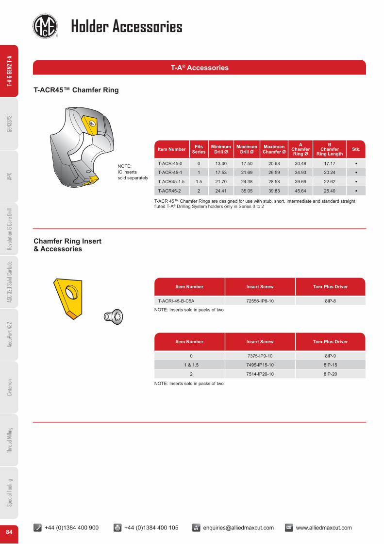
T-ACR45™ Chamfer Ring
Chamfer Ring Insert& Accessories
NOTE:IC insertssold separately
Item Number Fits Series
MinimumDrill Ø
MaximumDrill Ø
MaximumChamfer Ø
AChamferRing Ø
BChamfer
Ring LengthStk.
T-ACR-45-0 0 13.00 17.50 20.68 30.48 17.17 •T-ACR-45-1 1 17.53 21.69 26.59 34.93 20.24 •T-ACR45-1.5 1.5 21.70 24.38 28.58 39.69 22.62 •T-ACR45-2 2 24.41 35.05 39.83 45.64 25.40 •
Item Number Insert Screw Torx Plus Driver
T-ACRI-45-B-C5A 72556-IP8-10 8IP-8
Item Number Insert Screw Torx Plus Driver
0 7375-IP9-10 8IP-9
1 & 1.5 7495-IP15-10 8IP-15
2 7514-IP20-10 8IP-20
T-ACR 45™ Chamfer Rings are designed for use with stub, short, intermediate and standard straightfluted T-A® Drilling System holders only in Series 0 to 2
NOTE: Inserts sold in packs of two
NOTE: Inserts sold in packs of two
T-A
& GE
N2 T-
AGE
N3SY
SAP
XRe
volut
ion &
Cor
e Dril
lAS
C 32
0 So
lid C
arbid
eAc
cuPo
rt 43
2Cr
iterio
nTh
read
Milli
ngSp
ecial
Tooli
ng

+44 (0)1384 400 900 +44 (0)1384 400 105 [email protected] www.alliedmaxcut.com +44 (0)1384 400 900 +44 (0)1384 400 105 [email protected] www.alliedmaxcut.com85
Holder Accessories
T-A® Accessories
Rotary Coolant Adapters (RCA)
Coolant Pipe Extension/Steady Bar
Solid Steady Bar
Fast Action Coupling
ItemNumber
(A)I.D.
(B)O.D.
(C)Width
(D) ThreadDriving Rod
(E)Pipe Tap
2T-2SRM 19.05 44.45 22.23 M8 1/8"
2T-3SRM 25.40 53.97 28.57 M8 1/8"
2T-4SRM 31.75 63.50 34.92 M10 1/4"
2T-5SRM 44.45 76.20 34.92 M10 1/4"
2T-6SRM 57.15 95.27 44.45 M12 1/2"
ItemNumber
Nominal PipeThread E L1 mm
302T-2SRM 1/8" 150302T-3SRM 1/8" 150302T-4SRM 1/4" 200302T-5SRM 1/4" 200302T-6SRM 1/2" 200
ItemNumber
ThreadSize E L1 mm
312T-2SRM M8 250312T-3SRM M8 250312T-4SRM M10 250312T-5SRM M10 250312T-6SRM M12 250
ItemNumber
Nominal PipeThread E Hose Ø
322T-2SRM 1/8" 9mm322T-3SRM 1/8" 9mm322T-4SRM 1/4" 9mm322T-5SRM 1/4" 12mm322T-6SRM 1/2" 12mm
Items included: (1) Inducer Ring, (2) O-Rings, (2) Snap Rings and (2) Thrust Washers.
For RCA repair kit see page 86.
Note: Always use a steady bar when using a RCA adaptor
Note: Always use a steady bar when using a RCA adaptor
AB
E PIPE THREADPer BSP & ISO 7-1
D THREAD
C
L1
E
E
E
L1
E
T-A
& GE
N2 T-
AGE
N3SY
SAP
XRe
volut
ion &
Cor
e Dril
lAS
C 32
0 So
lid C
arbid
eAc
cuPo
rt 43
2Cr
iterio
nTh
read
Milli
ngSp
ecial
Tooli
ng

+44 (0)1384 400 900 +44 (0)1384 400 105 [email protected] www.alliedmaxcut.com +44 (0)1384 400 900 +44 (0)1384 400 105 [email protected] www.alliedmaxcut.com86
Adaptors
RCA Assembly
RCA Assembly & Repair Kit
Hose
Fast Action Coupling
Rotary Coolant Adapter
Thrust WasherRetaining Ring
T-A® InsertT-A® Holder
Stud to providepositive stopSolid steady bar
assembled into RCA
Spindle
Non-rotatingmember ofmachine
Catalogue Number
Item Number Drill Range RCA Repair Kit
2T-2SRM 9.50 - 11.07mm 2T1-2SR
2T-2SRM 11.10 - 12.95mm 2T1-2SR
2T-2SRM 12.98 - 17.65mm 2T1-2SR
2T-3SRM 17.53 - 24.38mm 2T1-3SR
2T-3SRM 24.41 - 35.05mm 2T1-3SR
2T-4SRM 30.00 - 35.05mm 2T1-4SR
2T-4SRM 34.37 - 47.80mm 2T1-4SR
2T-5SRM 46.99 - 65.28mm 2T1-5SR
2T-6SRM 62.38 - 89.08mm 2T1-6SR
2T-6SRM 87.76 - 160.00mm 2T1-6SR
RCA Repair Kit includes: (2) O-Rings, (2) Snap Rings and (2) Thrust Washers
T-A
& GE
N2 T-
AGE
N3SY
SAP
XRe
volut
ion &
Cor
e Dril
lAS
C 32
0 So
lid C
arbid
eAc
cuPo
rt 43
2Cr
iterio
nTh
read
Milli
ngSp
ecial
Tooli
ng
+44 (0)1384 400 900 +44 (0)1384 400 105 [email protected] www.alliedmaxcut.com +44 (0)1384 400 900 +44 (0)1384 400 105 [email protected] www.alliedmaxcut.com87
Adaptors
Catalogue Number
Item Number Drill Range RCA Repair Kit
2T-2SRM 9.50 - 11.07mm 2T1-2SR
2T-2SRM 11.10 - 12.95mm 2T1-2SR
2T-2SRM 12.98 - 17.65mm 2T1-2SR
2T-3SRM 17.53 - 24.38mm 2T1-3SR
2T-3SRM 24.41 - 35.05mm 2T1-3SR
2T-4SRM 30.00 - 35.05mm 2T1-4SR
2T-4SRM 34.37 - 47.80mm 2T1-4SR
2T-5SRM 46.99 - 65.28mm 2T1-5SR
2T-6SRM 62.38 - 89.08mm 2T1-6SR
2T-6SRM 87.76 - 160.00mm 2T1-6SR
RCA Repair Kit includes: (2) O-Rings, (2) Snap Rings and (2) Thrust Washers
T-A® Adaptor
L2
L1
D1
D2D3DV50SHANK
Item Number OuterTaper
D1 InnerØ mm
D2Ø
D3Ø L1 L2 Qty of
Clamping Screws Stk.
AMDV50-EM50-120 DV50 50 100 69.85 100 120 2 l
DIN69871-A
Excludes Lateral SideCoolant Hole
DV50 Adaptor
L2
L1
D1
D2D3DV45SHANK
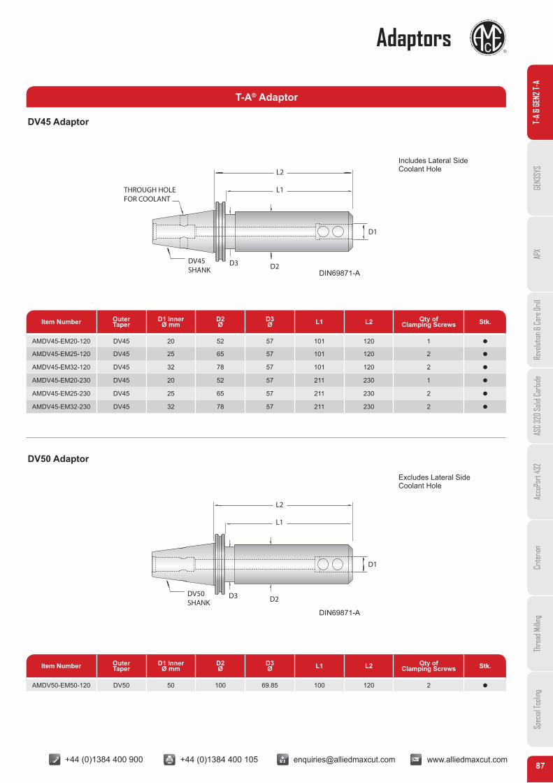
THROUGH HOLEFOR COOLANT
Item Number OuterTaper
D1 InnerØ mm
D2Ø
D3Ø L1 L2 Qty of
Clamping Screws Stk.
AMDV45-EM20-120 DV45 20 52 57 101 120 1 l
AMDV45-EM25-120 DV45 25 65 57 101 120 2 l
AMDV45-EM32-120 DV45 32 78 57 101 120 2 l
AMDV45-EM20-230 DV45 20 52 57 211 230 1 l
AMDV45-EM25-230 DV45 25 65 57 211 230 2 l
AMDV45-EM32-230 DV45 32 78 57 211 230 2 l
DIN69871-A
Includes Lateral SideCoolant Hole
DV45 Adaptor T-A
& GE
N2 T-
AGE
N3SY
SAP
XRe
volut
ion &
Cor
e Dril
lAS
C 32
0 So
lid C
arbid
eAc
cuPo
rt 43
2Cr
iterio
nTh
read
Milli
ngSp
ecial
Tooli
ng

+44 (0)1384 400 900 +44 (0)1384 400 105 [email protected] www.alliedmaxcut.com +44 (0)1384 400 900 +44 (0)1384 400 105 [email protected] www.alliedmaxcut.com88
Adaptors
HolderSeries Drill Range
Catalogue NumberMaximum
Torque (N/cm)TORX Plus®
Hand DriversTORX Plus®
Screws*Nylon LockingTORX Screws*
Y 9.5mm - 11.07mm 8IP-7 724-IP7-10 724N-IP7-10 84
Z 11.1mm - 12.95mm 8IP-7 7247-IP7-10 7247N-IP7-10 84
0 12.98mm - 17.65mm 8IP-8 72556-IP8-10 72556N-IP8-10 175
0.5 15.5mm - 17.65mm 8IP-8 72567-IP8-10 72567N-IP8-10 175
1 17.53mm - 24.38mm 8IP-9 7375-IP9-10 7375N-IP9-10 305
1.5 22.0mm - 24.38mm 8IP-9 739-IP9-10 739N-IP9-10 305
2, 2.5 24.41mm - 35.05mm 8IP-15 7495-IP15-10 7495N-IP15-10 690
3, 4 34.37mm - 65.28mm 8IP-20 7514-IP20-10 7514N-IP20-10 1370
5-8 62.38mm - 160.00mm 8IP-25 7619-IP25-10 N/A 1750
T-A® Replacement TORX Plus Screws and Driver information
*Supplied in 10 piece packages.
T-A
& GE
N2 T-
AGE
N3SY
SAP
XRe
volut
ion &
Cor
e Dril
lAS
C 32
0 So
lid C
arbid
eAc
cuPo
rt 43
2Cr
iterio
nTh
read
Milli
ngSp
ecial
Tooli
ng
T-A® Adaptors
Item Number OuterTaper
D InnerØ mm
L1 mm
L2 mm
D Ø mm
4020-5SRM QC40 20 188.00 94.00 76.20
4025-5SRM QC40 25 199.00 106.00 76.20
5020-5SRM DT50 20 227.00 100.00 76.20
5025-5SRM DT50 25 239.00 112.00 76.20
5032-6SRM ST50 32 254.00 127.00 95.27
Max coolant Pressure: 40 Bar. Max RPM: 3000. Suitable for Holders: Y, Z, 0, 0.5, 1, 1.5, 2.0, 2.5 series
Note: DIN 69871-A and BT50 tapers available upon request
L1
L2
D
DIN 2080 ISO Taper Shank Coolant Fed Holders
+44 (0)1384 400 900 +44 (0)1384 400 105 [email protected] www.alliedmaxcut.com +44 (0)1384 400 900 +44 (0)1384 400 105 [email protected] www.alliedmaxcut.com89
T-A® Insert System Guidelines
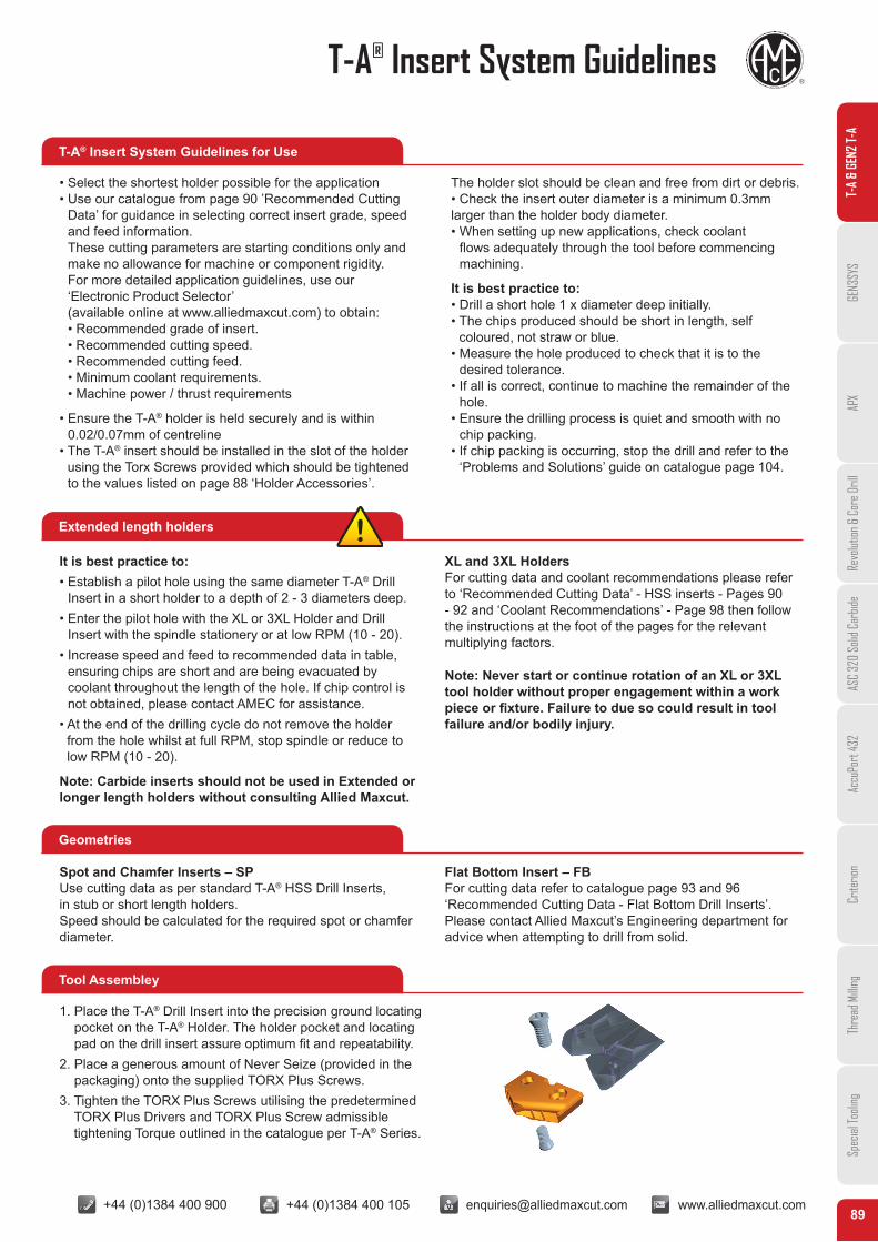
T-A® Insert System Guidelines for Use
Extended length holders
Geometries
Tool Assembley
• Select the shortest holder possible for the application• Use our catalogue from page 90 ’Recommended Cutting
Data’ for guidance in selecting correct insert grade, speed and feed information. These cutting parameters are starting conditions only and make no allowance for machine or component rigidity. For more detailed application guidelines, use our ‘Electronic Product Selector’ (available online at www.alliedmaxcut.com) to obtain: • Recommended grade of insert. • Recommended cutting speed. • Recommended cutting feed. • Minimum coolant requirements. • Machine power / thrust requirements
• Ensure the T-A® holder is held securely and is within 0.02/0.07mm of centreline
• The T-A® insert should be installed in the slot of the holder using the Torx Screws provided which should be tightened to the values listed on page 88 ‘Holder Accessories’.
The holder slot should be clean and free from dirt or debris. • Check the insert outer diameter is a minimum 0.3mm larger than the holder body diameter.• When setting up new applications, check coolant
flows adequately through the tool before commencing machining.
It is best practice to:• Drill a short hole 1 x diameter deep initially.• The chips produced should be short in length, self
coloured, not straw or blue.• Measure the hole produced to check that it is to the
desired tolerance.• If all is correct, continue to machine the remainder of the
hole.• Ensure the drilling process is quiet and smooth with no
chip packing.• If chip packing is occurring, stop the drill and refer to the
‘Problems and Solutions’ guide on catalogue page 104.
It is best practice to:• Establish a pilot hole using the same diameter T-A® Drill
Insert in a short holder to a depth of 2 - 3 diameters deep.• Enter the pilot hole with the XL or 3XL Holder and Drill
Insert with the spindle stationery or at low RPM (10 - 20).• Increase speed and feed to recommended data in table,
ensuring chips are short and are being evacuated by coolant throughout the length of the hole. If chip control is not obtained, please contact AMEC for assistance.
• At the end of the drilling cycle do not remove the holder from the hole whilst at full RPM, stop spindle or reduce to low RPM (10 - 20).
Note: Carbide inserts should not be used in Extended or longer length holders without consulting Allied Maxcut.
XL and 3XL Holders For cutting data and coolant recommendations please refer to ‘Recommended Cutting Data’ - HSS inserts - Pages 90 - 92 and ‘Coolant Recommendations’ - Page 98 then follow the instructions at the foot of the pages for the relevant multiplying factors.
Note: Never start or continue rotation of an XL or 3XL tool holder without proper engagement within a work piece or fixture. Failure to due so could result in tool failure and/or bodily injury.
Spot and Chamfer Inserts – SPUse cutting data as per standard T-A® HSS Drill Inserts,in stub or short length holders.Speed should be calculated for the required spot or chamferdiameter.
Flat Bottom Insert – FBFor cutting data refer to catalogue page 93 and 96‘Recommended Cutting Data - Flat Bottom Drill Inserts’.Please contact Allied Maxcut’s Engineering department for advice when attempting to drill from solid.
1. Place the T-A® Drill Insert into the precision ground locating pocket on the T-A® Holder. The holder pocket and locating pad on the drill insert assure optimum fit and repeatability.
2. Place a generous amount of Never Seize (provided in the packaging) onto the supplied TORX Plus Screws.
3. Tighten the TORX Plus Screws utilising the predetermined TORX Plus Drivers and TORX Plus Screw admissible tightening Torque outlined in the catalogue per T-A® Series.
T-A
& GE
N2 T-
AGE
N3SY
SAP
XRe
volut
ion &
Cor
e Dril
lAS
C 32
0 So
lid C
arbid
eAc
cuPo
rt 43
2Cr
iterio
nTh
read
Milli
ngSp
ecial
Tooli
ng

+44 (0)1384 400 900 +44 (0)1384 400 105 [email protected] www.alliedmaxcut.com +44 (0)1384 400 900 +44 (0)1384 400 105 [email protected] www.alliedmaxcut.com90
Technical Section Recommended Cutting Data – HSS Drill Inserts Y-2 Series
MaterialHardness Speed
AM200®
M/min
Feed mm/rev
BHN kg N/mm2 9.5-12.95 12.98-17.53 17.53-24.38 24.41-35
Free Machining Steel100-150 38-50 370-500 99 0.20 0.30 0.41 0.48150-200 50-70 500-700 91 0.18 0.28 0.38 0.43200-250 70-88 700-870 85 0.15 0.25 0.36 0.41
Low Carbon Steel
85-125 30-46 300-450 88 0.20 0.25 0.36 0.46125-175 46-62 450-600 83 0.18 0.25 0.36 0.43175-225 62-77 600-775 79 0.15 0.23 0.33 0.41225-275 77-96 775-940 73 0.13 0.23 0.33 0.41
Medium Carbon Steel
125-175 46-62 450-600 83 0.18 0.25 0.36 0.43175-225 62-77 600-775 79 0.15 0.23 0.33 0.41225-275 77-96 775-940 73 0.15 0.23 0.33 0.41275-325 96-111 940-1090 68 0.13 0.20 0.30 0.38
Alloy Steel
125-175 46-62 450-600 73 0.18 0.25 0.36 0.41175-225 62-77 600-775 68 0.15 0.23 0.33 0.41225-275 77-96 775-940 64 0.15 0.23 0.33 0.43275-325 96-111 940-1090 59 0.13 0.20 0.30 0.38325-375 111-129 1090-1265 54 0.10 0.18 0.28 0.36
High Strength Steel225-300 77-104 600-1020 38 0.15 0.23 0.28 0.33300-350 104-121 1020-1180 30 0.13 0.20 0.25 0.30350-400 121-139 1180-1365 24 0.10 0.18 0.23 0.28
Structural Steel100-150 38-50 370-500 71 0.20 0.28 0.38 0.43150-250 50-88 500-850 57 0.15 0.25 0.33 0.38250-350 88-121 850-1180 48 0.13 0.23 0.30 0.33
Tool Steel150-200 50-70 500-700 38 0.10 0.18 0.25 0.30200-250 70-88 700-870 32 0.10 0.18 0.25 0.30
High Temp Alloy140-220 49-77 480-755 13 0.10 0.18 0.23 0.28223-310 77-101 755-990 12 0.10 0.15 0.20 0.25
Titanium Alloy140-220 49-77 480-755 16 0.10 0.18 0.21 0.27220-310 77-101 755-990 15 0.08 0.15 0.18 0.23
Aerospace Alloy S82
185-275 65-96 640-940 35 0.15 0.20 0.23 0.28275-350 96-121 940-1180 31 0.13 0.18 0.20 0.25
Stainless Steel 400 Series 416, 420, (303)
185-275 65-96 640-940 35 0.15 0.20 0.23 0.28275-350 96-121 940-1180 31 0.13 0.18 0.20 0.25
Stainless Steel 300 Series 304, 316, 17-4PH
135-185 49-65 480-640 35 0.08 0.18 0.20 0.28185-275 65-96 640-940 31 0.08 0.15 0.18 0.25
Super DuplexDuplex St/Stl
135-185 49-65 480-640 26 0.08 0.18 0.20 0.28185-275 65-96 640-940 22 0.08 0.15 0.18 0.25
Hardox400 139 1365 21 0.08 0.15 0.20 0.23500 160 1600 14 0.05 0.12 0.18 0.20600 210 2000 N/A N/A N/A N/A N/A
Hardened Steel300-400 104-139 1020-1365 29 0.10 0.15 0.23 0.27400-500 139+ 1365+ 14 0.06 0.12 0.18 0.24
SG/Nodular/ Grey/White Cast Iron
120-150 44-50 430-500 84 0.20 0.30 0.41 0.51150-200 50-70 500-700 79 0.18 0.28 0.38 0.48200-220 70-77 700-755 68 0.15 0.23 0.33 0.43220-260 77-90 755-890 57 0.13 0.20 0.28 0.36260-320 90-104 890-1020 47 0.13 0.18 0.25 0.28
Cast Aluminium30 10 100 (TICN) 229 0.23 0.38 0.46 0.58
180 62 600 (TICN) 122 0.20 0.33 0.40 0.50
Wrought Aluminium30 10 100 280 0.12 0.33 0.40 0.50
180 62 600 200 0.12 0.18 0.30 0.35
Aluminium Bronze100-200 38-68 370-670 82 0.15 0.24 0.30 0.38200-250 68-87 670-855 65 0.12 0.18 0.23 0.28
Brass 100 38 370 144 0.18 0.27 0.33 0.45Copper 60 21 200 58 0.07 0.10 0.18 0.26
Speed & Feed Multiplier forXL & 3XL tool length
When using the XL and 3XL holders, drillingparameters must be reduced (see table onopposite page).
Example – Using XL holderMaterial - Free machining steel (200BHN)Diameter & Hole Depth – 17.5mm x 280mmInsert – Original T-A 150N-17.5 TiCN coatedHolder – 27000S-20FM
CalculationSpeed M/min = 85X 0.80 (taken from speed & Feed Multiplier) = 68Feed (mm/rev) = 0.25 X 0.90 (taken from speed & Feed Multiplier) = 0.23
T-A
& GE
N2 T-
AGE
N3SY
SAP
XRe
volut
ion &
Cor
e Dril
lAS
C 32
0 So
lid C
arbid
eAc
cuPo
rt 43
2Cr
iterio
nTh
read
Milli
ngSp
ecial
Tooli
ng

+44 (0)1384 400 900 +44 (0)1384 400 105 [email protected] www.alliedmaxcut.com +44 (0)1384 400 900 +44 (0)1384 400 105 [email protected] www.alliedmaxcut.com91
Technical SectionRecommended Cutting Data – HSS Drill Inserts 3-8 Series
MaterialHardness
Tool SteelGrade
Speed M/min Feed (mm/rev)
BHN kg N/mm2 TiN AM200® 35 - 47.8 47.85 - 65 66 - 114.48
Free Machining Steel100-150 38-50 370-500 HSS/SC 61 99 0.51 0.58 0.71150-200 50-70 500-700 HSS/SC 55 91 0.51 0.58 0.71200-250 70-88 700-870 HSS/SC 49 85 0.51 0.58 0.71
Low Carbon Steel
85-125 30-46 300-450 HSS/SC 52 88 0.48 0.58 0.69125-175 46-62 450-600 HSS/SC 49 83 0.48 0.58 0.69175-225 62-77 600-775 HSS/SC 46 79 0.46 0.53 0.61225-275 77-96 775-940 HSS/SC 43 73 0.46 0.53 0.61
Medium Carbon Steel
125-175 46-62 450-600 HSS/SC 49 83 0.48 0.58 0.69175-225 62-77 600-775 HSS/SC 46 79 0.46 0.53 0.61225-275 77-96 775-940 HSS/SC 43 73 0.46 0.53 0.61275-325 96-111 940-1090 SC, PC 40 68 0.41 0.48 0.56
Alloy Steel
125-175 46-62 450-600 HSS/SC 46 73 0.43 0.48 0.56175-225 62-77 600-775 HSS/SC 43 68 0.43 0.48 0.56225-275 77-96 775-940 HSS/SC 40 64 0.43 0.48 0.56275-325 96-111 940-1090 SC, PC 37 59 0.38 0.43 0.51325-375 111-129 1090-1265 SC, PC 34 54 0.38 0.43 0.51
High Strength Steel225-300 77-104 600-1020 SC, PC 24 38 0.36 0.43 0.51300-350 104-121 1020-1180 SC, PC 18 30 0.36 0.43 0.51350-400 121-139 1180-1365 PC 15 24 0.30 0.41 0.46
Structural Steel100-150 38-50 370-500 HSS/SC 43 71 0.46 0.53 0.66150-250 50-88 500-850 HSS/SC 37 57 0.41 0.48 0.61250-350 88-121 850-1180 SC, PC 30 49 0.36 0.43 0.51
Tool Steel150-200 50-70 500-700 SC 24 38 0.30 0.38 0.43200-250 70-88 700-870 SC, PC 18 32 0.30 0.38 0.43
High Temp Alloy140-220 49-77 480-755 SC, PC 9 13 0.30 0.38 0.38223-310 77-101 755-990 PC 8 12 0.25 0.30 0.30
Titanium Alloy140-220 49-77 480-755 SC, PC 11 16 0.30 0.38 0.38220-310 77-101 755-990 PC 10 15 0.25 0.30 0.30
Aerospace Alloy S82
185-275 65-96 640-940 SC, PC 23 35 0.30 0.36 0.46275-350 96-121 940-1180 SC, PC 18 31 0.36 0.41 0.51
Stainless Steel 400 Series 416, 420, (303)
185-275 65-96 640-940 SC, PC 23 35 0.30 0.36 0.46275-350 96-121 940-1180 SC, PC 18 31 0.36 0.41 0.51
Stainless Steel 300 Series 304, 316, 17-4PH
135-185 49-65 480-640 SC, PC 23 35 0.30 0.36 0.46185-275 65-96 640-940 SC, PC 18 31 0.36 0.41 0.51
Super DuplexDuplex St/Stl
135-185 49-65 480-640 SC, PC 18 26 0.36 0.41 0.51185-275 65-96 640-940 SC, PC 15 22 0.30 0.36 0.46
Hardox400 139 1365 SC, PC 14 21 0.30 0.41 0.46500 160 1600 PC 10 14 0.25 0.30 0.40600 210 2000 N/A N/A N/A N/A N/A N/A
Hardened Steel300-400 104-139 1020-1365 PC 15 29 0.30 0.41 0.46400-500 139+ 1365+ PC 10 14 0.25 0.30 0.40
SG/Nodular/ Grey/White Cast Iron
120-150 44-50 430-500 HSS 52 84 0.61 0.69 0.76150-200 50-70 500-700 HSS 46 79 0.56 0.64 0.71200-220 70-77 700-755 HSS 40 68 0.46 0.53 0.61220-260 77-90 755-890 SC, PC 34 57 0.36 0.43 0.51260-320 90-104 890-1020 SC, PC 27 47 0.28 0.36 0.41
Cast Aluminium30 10 100 HSS 183 TiCN 229 0.56 0.64 0.64
180 62 600 HSS 91 TiCN 129 0.56 0.64 0.64
Wrought Aluminium30 10 100 HSS 183 200 0.56 0.64 0.64
180 62 600 HSS 91 150 0.56 0.64 0.64
Aluminium Bronze100-200 38-68 370-670 SC 52 82 0.43 0.48 0.53200-250 68-87 670-855 SC 40 65 0.36 0.40 0.46
Brass 100 38 370 HSS 91 144 0.47 0.53 0.58Copper 60 21 200 SC 40 58 0.23 0.27 0.31
Formulas: mm/min = rev/min • mm/rev M/min = rev/min • 0.003 • DIA rev/min = M/min • 318.47/DIA
Holder Length
Stub Short Intermediate Standard Extended Long XL 3XL
SPEED see above chart 0.90 0.85 0.80 0.75
FEED see above chart 0.95 0.90 0.90
SPEED AND FEED MULTIPLIER For various tool lengths
T-A
& GE
N2 T-
AGE
N3SY
SAP
XRe
volut
ion &
Cor
e Dril
lAS
C 32
0 So
lid C
arbid
eAc
cuPo
rt 43
2Cr
iterio
nTh
read
Milli
ngSp
ecial
Tooli
ng
For Deep Hole Drilling Guidelines refer to page 83 in the Technical Section.WARNING

+44 (0)1384 400 900 +44 (0)1384 400 105 [email protected] www.alliedmaxcut.com +44 (0)1384 400 900 +44 (0)1384 400 105 [email protected] www.alliedmaxcut.com92
Technical SectionRecommended Cutting Data – HSS Drill Inserts Y-8 Series
MaterialHardness Tool
SteelGrade
*
Speed M/min Feed (mm/rev) DW Cutting Data (110-160)
BHN kg N/mm2 TiN TiCN TiAIN 9.5-12.95
12.98-17.53
17.53-24.38
24.41-35
35-47.8
47.85-65
66-114.48
Speed M/min
Feed (mm/rev)
Free Machining Steel
100-150 38-50 370-500 HSS 61 80 86 0.18 0.25 0.33 0.41 0.51 0.58 0.7158-76 0.35150-200 50-70 500-700 HSS 55 72 80 0.18 0.25 0.33 0.41 0.51 0.58 0.71
200-250 70-88 700-870 HSS 49 64 73 0.15 0.25 0.33 0.41 0.51 0.58 0.71
Low Carbon Steel
85-125 30-46 300-450 HSS 52 67 76 0.15 0.23 0.30 0.38 0.48 0.58 0.69
48-66 0.3125-175 46-62 450-600 HSS 49 64 73 0.15 0.23 0.30 0.38 0.48 0.58 0.69175-225 62-77 600-775 HSS 46 60 69 0.13 0.20 0.25 0.36 0.46 0.53 0.61225-275 77-96 775-940 HSS 43 55 64 0.13 0.20 0.25 0.36 0.46 0.53 0.61
Medium Carbon Steel
125-175 46-62 450-600 HSS 49 64 73 0.15 0.23 0.30 0.38 0.48 0.58 0.69
48-66 0.3175-225 62-77 600-775 HSS 46 60 69 0.13 0.20 0.25 0.36 0.46 0.53 0.61225-275 77-96 775-940 HSS 43 55 64 0.13 0.20 0.25 0.36 0.46 0.53 0.61275-325 96-111 940-1090 SC, PC 40 52 60 0.10 0.18 0.23 0.30 0.41 0.48 0.56
Alloy Steel
125-175 46-62 450-600 HSS 46 60 64 0.15 0.20 0.25 0.36 0.43 0.48 0.56
30-36 0.28175-225 62-77 600-775 HSS 43 55 60 0.13 0.20 0.25 0.36 0.43 0.48 0.56225-275 77-96 775-940 HSS 40 52 55 0.13 0.18 0.25 0.36 0.43 0.48 0.56275-325 96-111 940-1090 SC, PC 37 47 52 0.10 0.15 0.23 0.30 0.38 0.43 0.51325-375 111-129 1090-1265 SC, PC 34 44 47 0.08 0.15 0.23 0.30 0.38 0.43 0.51 22-26 0.25
High Strength Steel
225-300 77-104 600-1020 SC, PC 24 31 34 0.13 0.18 0.23 0.25 0.36 0.43 0.5116-20 0.25300-350 104-121 1020-1180 SC, PC 18 24 26 0.10 0.18 0.23 0.25 0.36 0.43 0.51
350-400 121-139 1180-1365 PC 15 20 21 0.08 0.15 0.20 0.23 0.30 0.41 0.46
Structural Steel
100-150 38-50 370-500 HSS 43 55 61 0.15 0.25 0.30 0.36 0.46 0.53 0.6642-54 0.3150-250 50-88 500-850 HSS 37 47 52 0.13 0.23 0.25 0.30 0.41 0.48 0.61
250-350 88-121 850-1180 SC, PC 30 40 43 0.10 0.20 0.23 0.25 0.36 0.43 0.51
Tool Steel150-200 50-70 500-700 SC 24 32 34 0.10 0.15 0.20 0.25 0.30 0.38 0.43
31-38 0.23200-250 70-88 700-870 SC, PC 18 26 28 0.10 0.15 0.20 0.25 0.30 0.38 0.43
High Temp Alloy
140-220 49-77 480-755 SC, PC 9 11 12 0.08 0.18 0.20 0.25 0.30 0.38 0.38
N/A N/A
223-310 77-101 755-990 PC 8 9 11 0.08 0.15 0.18 0.20 0.25 0.30 0.30
Titanium Alloy
140-220 49-77 480-755 SC, PC 11 14 15 0.08 0.18 0.20 0.25 0.30 0.38 0.38220-310 77-101 755-990 PC 10 11 14 0.08 0.15 0.18 0.20 0.25 0.30 0.30
Aerospace Alloy S82
185-275 65-96 640-940 SC, PC 23 29 32 0.15 0.20 0.23 0.28 0.36 0.41 0.51275-350 96-121 940-1180 SC, PC 18 24 28 0.13 0.18 0.20 0.25 0.30 0.36 0.46
Stainless Steel 400 Series 416, 420, (303)
185-275 65-96 640-940 SC, PC 23 29 32 0.15 0.20 0.23 0.28 0.36 0.41 0.5122-29* 0.23*
275-350 96-121 940-1180 SC, PC 18 24 28 0.13 0.18 0.20 0.25 0.30 0.36 0.46Stainless Steel 300 Series 304, 316, 17-4PH
135-185 49-65 480-640 SC, PC 23 29 32 0.08 0.18 0.20 0.28 0.36 0.41 0.5122-29* 0.23*
185-275 65-96 640-940 SC, PC 18 24 28 0.08 0.15 0.18 0.25 0.30 0.36 0.46
Super DuplexDuplex St/Stl
135-185 49-65 480-640 SC, PC 18 22 24 0.08 0.18 0.20 0.28 0.36 0.41 0.5116-20* 0.23*
185-275 65-96 640-940 SC, PC 15 18 20 0.08 0.15 0.18 0.25 0.30 0.36 0.46
Hardox400 139 1365 SC, PC 14 17 21 0.08 0.15 0.20 0.23 0.30 0.41 0.46
N/A N/A500 160 1600 PC 10 12 14 0.05 0.12 0.18 0.20 0.25 0.30 0.40600 210 2000 N/A N/A N/A N/ N/A N/A N/A N/A N/A N/A N/A
Hardened Steel
300-400 104-139 1020-1365 PC 15 21 29 0.08 0.15 0.20 0.23 0.30 0.41 0.46N/A N/A
400-500 139+ 1365+ PC 10 12 14 0.05 0.12 0.18 0.20 0.25 0.30 0.40
SG/Nodular/ Grey/White Cast Iron
120-150 44-50 430-500 HSS 52 67 76 0.18 0.30 0.41 0.51 0.61 0.69 0.76
53-62 0.3150-200 50-70 500-700 HSS 46 60 69 0.15 0.28 0.36 0.46 0.56 0.64 0.71200-220 70-77 700-755 HSS 40 52 60 0.15 0.23 0.30 0.41 0.46 0.53 0.61220-260 77-90 755-890 SC, PC 34 44 50 0.13 0.18 0.23 0.30 0.36 0.43 0.51260-320 90-104 890-1020 SC, PC 27 37 41 0.1 0.15 0.18 0.23 0.28 0.36 0.41
Cast Aluminium
30 10 100 HSS 183 229 260 0.2 0.33 0.41 0.50 0.56 0.64 0.64109-146 0.32
180 62 600 HSS 91 122 138 0.2 0.33 0.41 0.46 0.56 0.64 0.64
Wrought Aluminium
30 10 100 HSS 183 229 260 0.1 0.15 0.25 0.30 0.56 0.64 0.64109-146 0.32
180 62 600 HSS 91 122 138 0.2 0.33 0.41 0.46 0.56 0.64 0.64
Aluminium Bronze
100-200 38-68 370-670 SC 52 67 76 0.15 0.28 0.36 0.46 0.56 0.66 0.7135-44 0.3
200-250 68-87 670-855 SC 40 52 59 0.13 0.18 0.23 0.30 0.36 0.43 0.51Brass 100 38 370 HSS 91 122 137 0.18 0.30 0.41 0.51 0.61 0.71 0.76 79-99 0.38Copper 60 21 200 SC 40 45 50 0.05 0.08 0.15 0.20 0.25 0.35 0.40 29-36 0.2
Formulas: mm/min = rev/min • mm/rev M/min = rev/min • 0.003 • DIA rev/min = M/min • 318.47/DIA*only applicable up to 120mm
Holder Length
Stub Short Intermediate Standard Extended Long XL 3XL
SPEED see above chart 0.90 0.85 0.80 0.75
FEED see above chart 0.95 0.90 0.90
SPEED AND FEED MULTIPLIER For various tool lengths
AMEC
T-A®
Original
T-A
& GE
N2 T-
AGE
N3SY
SAP
XRe
volut
ion &
Cor
e Dril
lAS
C 32
0 So
lid C
arbid
eAc
cuPo
rt 43
2Cr
iterio
nTh
read
Milli
ngSp
ecial
Tooli
ng
For Deep Hole Drilling Guidelines refer to page 83 in the Technical Section.WARNING

+44 (0)1384 400 900 +44 (0)1384 400 105 [email protected] www.alliedmaxcut.com +44 (0)1384 400 900 +44 (0)1384 400 105 [email protected] www.alliedmaxcut.com93
Technical SectionRecommended Cutting Data - HSS Flat Bottom Drill Inserts Y-4 Series
AMEC
T-A®
Original
MaterialHardness Speed M/min Feed (mm/rev)
BHN kg N/mm2 TiN TiCN TiAIN 9.5 –12.95mm
12.98 –17.53mm
17.53 –24.38mm
24.41 –35mm
34.37 –47.80mm
47.85 –65mm
Free Machining Steel100-150 38-50 370-500 52 70 76 0.15 0.23 0.28 0.35 0.41 0.46150-200 50-70 500-700 47 62 70 0.15 0.23 0.28 0.35 0.41 0.46200-250 70-88 700-870 43 56 64 0.13 0.23 0.28 0.35 0.38 0.43
Low Carbon Steel
85-125 30-46 300-450 46 59 67 0.13 0.20 0.25 0.33 0.38 0.43125-175 46-62 450-600 43 56 64 0.13 0.20 0.25 0.33 0.38 0.41175-225 62-77 600-775 40 53 59 0.10 0.18 0.23 0.30 0.36 0.41225-275 77-96 775-940 37 47 56 0.10 0.18 0.23 0.30 0.36 0.38
Medium Carbon Steel
125-175 46-62 450-600 43 56 64 0.13 0.20 0.25 0.33 0.38 0.46175-225 62-77 600-775 40 53 59 0.10 0.18 0.23 0.30 0.36 0.43225-275 77-96 775-940 37 47 56 0.10 0.18 0.23 0.30 0.36 0.43275-325 96-111 940-1090 34 46 53 0.10 0.15 0.20 0.25 0.33 0.38
Alloy Steel
125-175 46-62 450-600 40 53 56 0.13 0.18 0.23 0.30 0.33 0.41175-225 62-77 600-775 37 47 53 0.10 0.18 0.23 0.30 0.33 0.41225-275 77-96 775-940 34 44 47 0.10 0.15 0.23 0.30 0.33 0.41275-325 96-111 940-1090 32 41 44 0.10 0.13 0.20 0.25 0.30 0.38325-375 111-129 1090-1265 29 38 41 0.08 0.13 0.20 0.25 0.30 0.36
High Strength Steel225-300 77-104 600-1020 21 26 29 0.10 0.15 0.20 0.23 0.25 0.30300-350 104-121 1020-1180 15 21 23 0.08 0.15 0.20 0.23 0.25 0.30350-400 121-139 1180-1365 13 18 20 0.08 0.13 0.18 0.20 0.23 0.28
Structural Steel100-150 38-50 370-500 36 47 52 0.13 0.23 0.25 0.30 0.38 0.43150-250 50-88 500-850 32 41 44 0.10 0.20 0.23 0.25 0.33 0.41250-350 88-121 850-1180 26 34 37 0.10 0.18 0.20 0.23 0.30 0.38
Tool Steel150-200 50-70 500-700 21 27 29 0.10 0.13 0.18 0.23 0.25 0.30200-250 70-88 700-870 15 23 24 0.10 0.13 0.18 0.23 0.23 0.28
High Temp Alloy140-220 49-77 480-755 7 9 10 0.08 0.15 0.18 0.23 0.25 0.30223-310 77-101 755-990 6 7 9 0.08 0.13 0.15 0.18 0.20 0.25
Titanium Alloy140-220 49-77 480-755 10 12 14 0.08 0.15 0.18 0.23 0.25 0.30220-310 77-101 755-990 8 11 12 0.08 0.13 0.15 0.18 0.20 0.25
Aerospace Alloy S82
185-275 65-96 640-940 20 26 27 0.13 0.18 0.20 0.25 0.30 0.38275-350 96-121 940-1180 15 21 24 0.10 0.15 0.18 0.23 0.25 0.30
Stainless Steel 400 Series 416, 420, (303)
185-275 65-96 640-940 20 26 27 0.13 0.18 0.20 0.25 0.30 0.36275-350 96-121 940-1180 15 21 24 0.10 0.15 0.18 0.23 0.25 0.28
Stainless Steel 300 Series 304, 316, 17-4PH
135-185 49-65 480-640 20 26 27 0.13 0.18 0.20 0.25 0.30 0.36185-275 65-96 640-940 15 21 24 0.10 0.15 0.18 0.23 0.25 0.28
Super DuplexDuplex St/Stl
135-185 49-65 480-640 20 26 27 0.13 0.18 0.20 0.25 0.30 0.36185-275 65-96 640-940 15 21 24 0.10 0.15 0.18 0.23 0.25 0.28
Hardox400 139 1365500 160 1600 N/A N/A N/A N/A N/A N/A N/A N/A N/A600 210 2000
Hardened Steel300-400 104-139 1020-1365 13 18 20 0.08 0.13 0.18 0.20 0.27 0.38400-500 139+ 1365+ 8 10 12 0.06 0.10 0.15 0.18 0.23 0.28
SG/Nodular/ Grey/White Cast Iron
120-150 44-50 430-500 46 59 67 0.15 0.25 0.36 0.43 0.48 0.51150-200 50-70 500-700 40 53 59 0.13 0.23 0.30 0.41 0.46 0.48200-220 70-77 700-755 34 46 53 0.13 0.20 0.25 0.36 0.41 0.43220-260 77-90 755-890 29 38 46 0.10 0.15 0.20 0.25 0.33 0.33260-320 90-104 890-1020 24 32 37 0.10 0.13 0.15 0.20 0.25 0.25
Cast Aluminium30 10 100 160 198 228 0.18 0.28 0.36 0.43 0.46 0.48
180 62 600 79 107 122 0.18 0.28 0.36 0.41 0.43 0.48
Wrought Aluminium30 10 100 160 198 228 0.18 0.28 0.36 0.43 0.46 0.48
180 62 600 79 107 122 0.18 0.28 0.36 0.41 0.43 0.48
Aluminium Bronze100-200 38-68 370-670 40 53 59 0.13 0.23 0.30 0.41 0.51 0.61200-250 68-87 670-855 29 38 46 0.10 0.15 0.20 0.25 0.31 0.38
Brass 100 38 370 46 59 67 0.15 0.25 0.36 0.43 0.53 0.63Copper 60 21 200 35 40 45 0.05 0.08 0.15 0.20 0.25 0.35
Formulas: mm/min = rev/min • mm/rev M/min = rev/min • 0.003 • DIA rev/min = M/min • 318.47/DIA
Holder Length
Stub Short Intermediate Standard Extended Long XL 3XL
SPEED see above chart 0.90 0.85 0.80 0.75
FEED see above chart 0.95 0.90 0.90
SPEED AND FEED MULTIPLIER For various tool lengths
T-A
& GE
N2 T-
AGE
N3SY
SAP
XRe
volut
ion &
Cor
e Dril
lAS
C 32
0 So
lid C
arbid
eAc
cuPo
rt 43
2Cr
iterio
nTh
read
Milli
ngSp
ecial
Tooli
ng
For Deep Hole Drilling Guidelines refer to page 83 in the Technical Section.WARNING
+44 (0)1384 400 900 +44 (0)1384 400 105 [email protected] www.alliedmaxcut.com +44 (0)1384 400 900 +44 (0)1384 400 105 [email protected] www.alliedmaxcut.com94
Technical Section
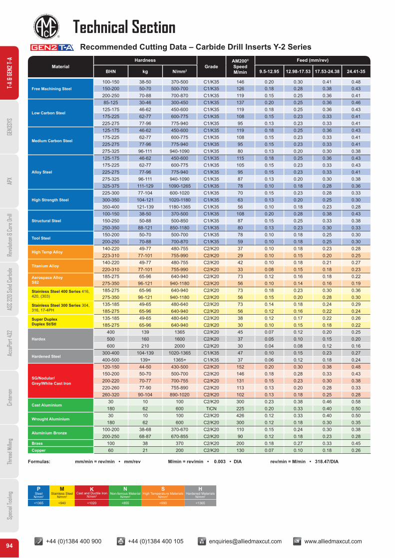
Formulas: mm/min = rev/min • mm/rev M/min = rev/min • 0.003 • DIA rev/min = M/min • 318.47/DIA
Recommended Cutting Data – Carbide Drill Inserts Y-2 Series
MaterialHardness
GradeAM200®
SpeedM/min
Feed (mm/rev)
BHN kg N/mm2 9.5-12.95 12.98-17.53 17.53-24.38 24.41-35
Free Machining Steel100-150 38-50 370-500 C1/K35 146 0.20 0.30 0.41 0.48150-200 50-70 500-700 C1/K35 126 0.18 0.28 0.38 0.43200-250 70-88 700-870 C1/K35 119 0.15 0.25 0.36 0.41
Low Carbon Steel
85-125 30-46 300-450 C1/K35 137 0.20 0.25 0.36 0.46125-175 46-62 450-600 C1/K35 119 0.18 0.25 0.36 0.43175-225 62-77 600-775 C1/K35 108 0.15 0.23 0.33 0.41225-275 77-96 775-940 C1/K35 95 0.13 0.23 0.33 0.41
Medium Carbon Steel
125-175 46-62 450-600 C1/K35 119 0.18 0.25 0.36 0.43175-225 62-77 600-775 C1/K35 108 0.15 0.23 0.33 0.41225-275 77-96 775-940 C1/K35 95 0.15 0.23 0.33 0.41275-325 96-111 940-1090 C1/K35 80 0.13 0.20 0.30 0.38
Alloy Steel
125-175 46-62 450-600 C1/K35 115 0.18 0.25 0.36 0.43175-225 62-77 600-775 C1/K35 105 0.15 0.23 0.33 0.43225-275 77-96 775-940 C1/K35 95 0.15 0.23 0.33 0.41275-325 96-111 940-1090 C1/K35 87 0.13 0.20 0.30 0.38325-375 111-129 1090-1265 C1/K35 78 0.10 0.18 0.28 0.36
High Strength Steel225-300 77-104 600-1020 C1/K35 70 0.15 0.23 0.28 0.33300-350 104-121 1020-1180 C1/K35 63 0.13 0.20 0.25 0.30350-400 121-139 1180-1365 C1/K35 56 0.10 0.18 0.23 0.28
Structural Steel100-150 38-50 370-500 C1/K35 108 0.20 0.28 0.38 0.43150-250 50-88 500-850 C1/K35 87 0.15 0.25 0.33 0.38250-350 88-121 850-1180 C1/K35 80 0.13 0.23 0.30 0.33
Tool Steel150-200 50-70 500-700 C1/K35 78 0.10 0.18 0.25 0.30200-250 70-88 700-870 C1/K35 59 0.10 0.18 0.25 0.30
High Temp Alloy140-220 49-77 480-755 C2/K20 37 0.10 0.18 0.23 0.28223-310 77-101 755-990 C2/K20 29 0.10 0.15 0.20 0.25
Titanium Alloy140-220 49-77 480-755 C2/K20 42 0.10 0.18 0.21 0.27220-310 77-101 755-990 C2/K20 33 0.08 0.15 0.18 0.23
Aerospace Alloy S82
185-275 65-96 640-940 C2/K20 73 0.12 0.16 0.18 0.22275-350 96-121 940-1180 C2/K20 56 0.10 0.14 0.16 0.19
Stainless Steel 400 Series 416, 420, (303)
185-275 65-96 640-940 C2/K20 73 0.18 0.23 0.30 0.36275-350 96-121 940-1180 C2/K20 56 0.15 0.20 0.28 0.30
Stainless Steel 300 Series 304, 316, 17-4PH
135-185 49-65 480-640 C2/K20 73 0.14 0.18 0.24 0.29185-275 65-96 640-940 C2/K20 56 0.12 0.16 0.22 0.24
Super DuplexDuplex St/Stl
135-185 49-65 480-640 C2/K20 38 0.12 0.17 0.22 0.26185-275 65-96 640-940 C2/K20 30 0.10 0.15 0.18 0.22
Hardox400 139 1365 C2/K20 45 0.07 0.12 0.20 0.25500 160 1600 C2/K20 37 0.05 0.10 0.15 0.20600 210 2000 C2/K20 30 0.04 0.08 0.12 0.16
Hardened Steel300-400 104-139 1020-1365 C1/K35 47 0.10 0.15 0.23 0.27400-500 139+ 1365+ C1/K35 37 0.06 0.12 0.18 0.24
SG/Nodular/ Grey/White Cast Iron
120-150 44-50 430-500 C2/K20 152 0.20 0.30 0.38 0.48150-200 50-70 500-700 C2/K20 146 0.18 0.28 0.33 0.43200-220 70-77 700-755 C2/K20 131 0.15 0.23 0.30 0.38220-260 77-90 755-890 C2/K20 113 0.13 0.20 0.28 0.33260-320 90-104 890-1020 C2/K20 102 0.13 0.18 0.25 0.28
Cast Aluminium30 10 100 C2/K20 300 0.23 0.38 0.46 0.58
180 62 600 TiCN 225 0.20 0.33 0.40 0.50
Wrought Aluminium30 10 100 C2/K20 426 0.12 0.33 0.40 0.50
180 62 600 C2/K20 300 0.12 0.18 0.30 0.35
Aluminium Bronze100-200 38-68 370-670 C2/K20 110 0.15 0.24 0.30 0.38200-250 68-87 670-855 C2/K20 90 0.12 0.18 0.23 0.28
Brass 100 38 370 C2/K20 200 0.18 0.27 0.33 0.45Copper 60 21 200 C2/K20 130 0.07 0.10 0.18 0.26
PSteel
N/mm2
MStainless Steel
N/mm2
KCast and Ductile Iron
N/mm2
NNon-ferrous Material
N/mm2
SHigh Temperature Materials
N/mm2
HHardened Materials
N/mm2
<1365 <940 <1020 <855 <990 <1365
T-A
& GE
N2 T-
AGE
N3SY
SAP
XRe
volut
ion &
Cor
e Dril
lAS
C 32
0 So
lid C
arbid
eAc
cuPo
rt 43
2Cr
iterio
nTh
read
Milli
ngSp
ecial
Tooli
ng
+44 (0)1384 400 900 +44 (0)1384 400 105 [email protected] www.alliedmaxcut.com +44 (0)1384 400 900 +44 (0)1384 400 105 [email protected] www.alliedmaxcut.com95
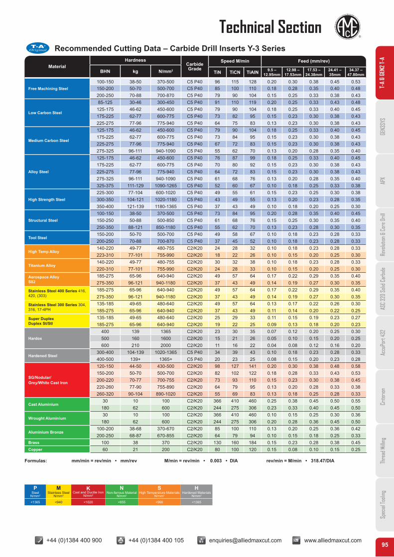
Technical SectionRecommended Cutting Data – Carbide Drill Inserts Y-3 Series
AMEC
T-A®
Original
Formulas: mm/min = rev/min • mm/rev M/min = rev/min • 0.003 • DIA rev/min = M/min • 318.47/DIA
MaterialHardness
CarbideGrade
Speed M/min Feed (mm/rev)
BHN kg N/mm2 TiN TiCN TiAIN 9.5 –12.95mm
12.98 –17.53mm
17.53 –24.38mm
24.41 –35mm
34.37 – 47.80mm
Free Machining Steel100-150 38-50 370-500 C5 P40 96 115 128 0.20 0.30 0.38 0.45 0.53150-200 50-70 500-700 C5 P40 85 100 110 0.18 0.28 0.35 0.40 0.48200-250 70-88 700-870 C5 P40 79 90 104 0.15 0.25 0.33 0.38 0.43
Low Carbon Steel
85-125 30-46 300-450 C5 P40 91 110 119 0.20 0.25 0.33 0.43 0.48125-175 46-62 450-600 C5 P40 79 90 104 0.18 0.25 0.33 0.40 0.45175-225 62-77 600-775 C5 P40 73 82 95 0.15 0.23 0.30 0.38 0.43225-275 77-96 775-940 C5 P40 64 75 83 0.13 0.23 0.30 0.38 0.43
Medium Carbon Steel
125-175 46-62 450-600 C5 P40 79 90 104 0.18 0.25 0.33 0.40 0.45175-225 62-77 600-775 C5 P40 73 84 95 0.15 0.23 0.30 0.38 0.43225-275 77-96 775-940 C5 P40 67 72 83 0.15 0.23 0.30 0.38 0.43275-325 96-111 940-1090 C5 P40 55 62 70 0.13 0.20 0.28 0.35 0.40
Alloy Steel
125-175 46-62 450-600 C5 P40 76 87 99 0.18 0.25 0.33 0.40 0.45175-225 62-77 600-775 C5 P40 70 80 92 0.15 0.23 0.30 0.38 0.43225-275 77-96 775-940 C5 P40 64 72 83 0.15 0.23 0.30 0.38 0.43275-325 96-111 940-1090 C5 P40 61 68 76 0.13 0.20 0.28 0.35 0.40325-375 111-129 1090-1265 C5 P40 52 60 67 0.10 0.18 0.25 0.33 0.38
High Strength Steel225-300 77-104 600-1020 C5 P40 49 55 61 0.15 0.23 0.25 0.30 0.38300-350 104-121 1020-1180 C5 P40 43 49 55 0.13 0.20 0.23 0.28 0.35350-400 121-139 1180-1365 C5 P40 37 43 49 0.10 0.18 0.20 0.25 0.30
Structural Steel100-150 38-50 370-500 C5 P40 73 84 95 0.20 0.28 0.35 0.40 0.45150-250 50-88 500-850 C5 P40 61 68 76 0.15 0.25 0.30 0.35 0.40250-350 88-121 850-1180 C5 P40 55 62 70 0.13 0.23 0.28 0.30 0.35
Tool Steel150-200 50-70 500-700 C5 P40 49 58 67 0.10 0.18 0.23 0.28 0.33200-250 70-88 700-870 C5 P40 37 45 52 0.10 0.18 0.23 0.28 0.33
High Temp Alloy140-220 49-77 480-755 C2/K20 24 28 32 0.10 0.18 0.23 0.28 0.33223-310 77-101 755-990 C2/K20 18 22 26 0.10 0.15 0.20 0.25 0.30
Titanium Alloy140-220 49-77 480-755 C2/K20 30 32 38 0.10 0.18 0.23 0.28 0.33220-310 77-101 755-990 C2/K20 24 28 33 0.10 0.15 0.20 0.25 0.30
Aerospace Alloy S82
185-275 65-96 640-940 C2/K20 49 57 64 0.17 0.22 0.29 0.35 0.40275-350 96-121 940-1180 C2/K20 37 43 49 0.14 0.19 0.27 0.30 0.35
Stainless Steel 400 Series 416, 420, (303)
185-275 65-96 640-940 C2/K20 49 57 64 0.17 0.22 0.29 0.35 0.40275-350 96-121 940-1180 C2/K20 37 43 49 0.14 0.19 0.27 0.30 0.35
Stainless Steel 300 Series 304, 316, 17-4PH
135-185 49-65 480-640 C2/K20 49 57 64 0.13 0.17 0.22 0.26 0.30185-275 65-96 640-940 C2/K20 37 43 49 0.11 0.14 0.20 0.22 0.25
Super DuplexDuplex St/Stl
135-185 49-65 480-640 C2/K20 25 29 33 0.11 0.15 0.19 0.23 0.27185-275 65-96 640-940 C2/K20 19 22 25 0.09 0.13 0.18 0.20 0.23
Hardox400 139 1365 C2/K20 23 30 35 0.07 0.12 0.20 0.25 0.30500 160 1600 C2/K20 15 21 26 0.05 0.10 0.15 0.20 0.25600 210 2000 C2/K20 11 16 22 0.04 0.08 0.12 0.16 0.20
Hardened Steel300-400 104-139 1020-1365 C5 P40 34 39 43 0.10 0.18 0.23 0.28 0.33400-500 139+ 1365+ C5 P40 20 23 25 0.08 0.15 0.20 0.23 0.28
SG/Nodular/ Grey/White Cast Iron
120-150 44-50 430-500 C2/K20 98 127 141 0.20 0.30 0.38 0.48 0.58150-200 50-70 500-700 C2/K20 82 102 122 0.18 0.28 0.33 0.43 0.53200-220 70-77 700-755 C2/K20 73 93 110 0.15 0.23 0.30 0.38 0.45220-260 77-90 755-890 C2/K20 64 79 95 0.13 0.20 0.28 0.33 0.38260-320 90-104 890-1020 C2/K20 55 69 83 0.13 0.18 0.25 0.28 0.33
Cast Aluminium30 10 100 C2/K20 366 410 460 0.25 0.38 0.45 0.50 0.55
180 62 600 C2/K20 244 275 306 0.23 0.33 0.40 0.45 0.50
Wrought Aluminium30 10 100 C2/K20 366 410 460 0.10 0.15 0.25 0.30 0.36
180 62 600 C2/K20 244 275 306 0.20 0.28 0.36 0.45 0.50
Aluminium Bronze100-200 38-68 370-670 C2/K20 85 100 110 0.13 0.20 0.25 0.36 0.42200-250 68-87 670-855 C2/K20 64 79 94 0.10 0.15 0.18 0.25 0.33
Brass 100 38 370 C2/K20 130 160 184 0.15 0.23 0.28 0.38 0.45Copper 60 21 200 C2/K20 80 100 120 0.15 0.08 0.10 0.15 0.25
PSteel
N/mm2
MStainless Steel
N/mm2
KCast and Ductile Iron
N/mm2
NNon-ferrous Material
N/mm2
SHigh Temperature Materials
N/mm2
HHardened Materials
N/mm2
<1365 <940 <1020 <855 <990 <1365
T-A
& GE
N2 T-
AGE
N3SY
SAP
XRe
volut
ion &
Cor
e Dril
lAS
C 32
0 So
lid C
arbid
eAc
cuPo
rt 43
2Cr
iterio
nTh
read
Milli
ngSp
ecial
Tooli
ng
+44 (0)1384 400 900 +44 (0)1384 400 105 [email protected] www.alliedmaxcut.com +44 (0)1384 400 900 +44 (0)1384 400 105 [email protected] www.alliedmaxcut.com96
Technical SectionT-
A &
GEN2
T-A
GEN3
SYS
APX
Revo
lution
& C
ore D
rill
ASC
320
Solid
Car
bide
Accu
Port
432
Crite
rion
Thre
ad M
illing
Spec
ial To
oling
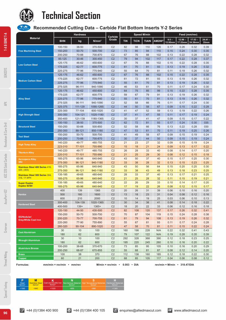
Recommended Cutting Data – Carbide Flat Bottom Inserts Y-2 SeriesAMEC
T-A®
Original
Formulas: mm/min = rev/min • mm/rev M/min = rev/min • 0.003 • DIA rev/min = M/min • 318.47/DIA
MaterialHardness
CarbideGrade
Speed M/min Feed (mm/rev)
BHN kg N/mm2 TiN TiCN TiAIN AM200® 9.5 –12.95mm
12.98 –17.53mm
17.53 –24.38mm
24.41 –35mm
Free Machining Steel100-150 38-50 370-500 C2 82 98 110 126 0.17 0.26 0.32 0.39150-200 50-70 500-700 C2 73 85 94 110 0.15 0.24 0.30 0.35200-250 70-88 700-870 C2 67 76 88 102 0.13 0.22 0.28 0.32
Low Carbon Steel
85-125 30-46 300-450 C2 79 94 102 117 0.17 0.22 0.28 0.37125-175 46-62 450-600 C2 67 76 88 102 0.15 0.22 0.28 0.35175-225 62-77 600-775 C2 61 70 81 93 0.13 0.19 0.26 0.32225-275 77-96 775-940 C2 55 64 70 81 0.11 0.19 0.26 0.32
Medium Carbon Steel
125-175 46-62 450-600 C2 67 76 88 102 0.15 0.22 0.28 0.35175-225 62-77 600-775 C2 61 72 81 93 0.13 0.19 0.26 0.32225-275 77-96 775-940 C2 55 61 70 81 0.13 0.19 0.26 0.32275-325 96-111 940-1090 C2 46 53 61 70 0.11 0.17 0.24 0.30
Alloy Steel
125-175 46-62 450-600 C2 64 75 85 99 0.15 0.22 0.28 0.35175-225 62-77 600-775 C2 59 67 79 91 0.13 0.19 0.26 0.32225-275 77-96 775-940 C2 55 61 70 81 0.13 0.19 0.26 0.32275-325 96-111 940-1090 C2 52 58 66 76 0.11 0.17 0.24 0.30325-375 111-129 1090-1265 C2 44 50 58 67 0.09 0.15 0.22 0.28
High Strength Steel225-300 77-104 600-1020 C2 41 47 52 59 0.13 0.19 0.22 0.26300-350 104-121 1020-1180 C2 37 41 47 55 0.11 0.17 0.19 0.24350-400 121-139 1180-1365 C2 30 37 41 47 0.09 0.15 0.17 0.22
Structural Steel100-150 38-50 370-500 C2 62 72 81 93 0.17 0.24 0.30 035150-250 50-88 500-850 C2 52 58 66 76 0.13 0.22 0.28 030250-350 88-121 850-1180 C2 47 53 61 70 0.11 0.19 0.25 0.26
Tool Steel150-200 50-70 500-700 C2 41 49 58 67 0.09 0.15 0.19 0.24200-250 70-88 700-870 C2 30 37 44 50 0.09 0.15 0.19 0.24
High Temp Alloy140-220 49-77 480-755 C2 21 23 27 32 0.09 0.15 0.19 0.24223-310 77-101 755-990 C2 15 18 21 24 0.09 0.13 0.17 0.22
Titanium Alloy140-220 49-77 480-755 C2 26 28 33 40 0.08 0.14 0.17 0.20220-310 77-101 755-990 C2 21 25 29 30 0.08 0.12 0.15 0.18
Aerospace Alloy S82
185-275 65-96 640-940 C2 43 50 37 40 0.15 0.17 0.25 0.30275-350 96-121 940-1180 C2 33 38 28 32 0.13 0.15 0.23 0.25
Stainless Steel 400 Series 416, 420, (303)
185-275 65-96 640-940 C2 43 50 56 64 0.15 0.20 0.25 0.30275-350 96-121 940-1180 C2 33 38 43 49 0.13 0.18 0.23 0.25
Stainless Steel 300 Series 304, 316, 17-4PH
135-185 49-65 480-640 C2 28 33 37 40 0.13 0.17 0.21 0.25185-275 65-96 640-940 C2 21 25 28 32 0.11 0.15 0.19 0.21
Super DuplexDuplex St/Stl
135-185 49-65 480-640 C2 22 26 29 33 0.10 0.14 0.17 0.20185-275 65-96 640-940 C2 17 19 22 26 0.08 0.12 0.15 0.17
Hardox400 139 1365 C2 20 26 31 39 0.06 0.10 0.16 0.20500 160 1600 C2 13 18 23 31 0.04 0.08 0.12 0.16600 210 2000 C2 10 14 19 25 0.03 0.06 0.10 0.13
Hardened Steel300-400 104-139 1020-1365 C2 30 34 38 41 0.08 0.14 0.18 0.22400-500 139+ 1365+ C2 18 20 22 33 0.06 0.12 0.16 0.18
SG/Nodular/ Grey/White Cast Iron
120-150 44-50 430-500 C2 82 108 120 137 0.17 0.26 0.32 0.41150-200 50-70 500-700 C2 70 87 104 119 0.15 0.24 0.28 0.38200-220 70-77 700-755 C2 61 79 94 108 0.13 0.19 0.26 0.32220-260 77-90 755-890 C2 55 67 81 93 0.11 0.17 0.24 0.28260-320 90-104 890-1020 C2 47 58 70 81 0.11 0.15 0.22 0.24
Cast Aluminium30 10 100 C2 160 198 228 N/A 0.22 0.32 0.41 0.43
180 62 600 C2 79 107 122 N/A 0.19 0.28 0.35 0.39
Wrought Aluminium30 10 100 C2 292 328 368 390 0.12 0.18 0.23 0.25
180 62 600 C2 195 220 245 260 0.10 0.16 0.20 0.22
Aluminium Bronze100-200 38-68 370-670 C2 73 85 95 105 0.10 0.16 0.20 0.29200-250 68-87 670-855 C2 55 68 81 87 0.08 0.12 0.14 0.20
Brass 100 38 370 C2 112 138 160 185 0.12 0.18 0.22 0.30Copper 60 21 200 C2 68 85 105 117 0.04 0.06 0.08 0.12
PSteel
N/mm2
MStainless Steel
N/mm2
KCast and Ductile Iron
N/mm2
NNon-ferrous Material
N/mm2
SHigh Temperature Materials
N/mm2
HHardened Materials
N/mm2
<1365 <940 <1020 <855 <990 <1365
+44 (0)1384 400 900 +44 (0)1384 400 105 [email protected] www.alliedmaxcut.com +44 (0)1384 400 900 +44 (0)1384 400 105 [email protected] www.alliedmaxcut.com97
Technical Section
T-A
& GE
N2 T-
AGE
N3SY
SAP
XRe
volut
ion &
Cor
e Dril
lAS
C 32
0 So
lid C
arbid
eAc
cuPo
rt 43
2Cr
iterio
nTh
read
Milli
ngSp
ecial
Tooli
ng
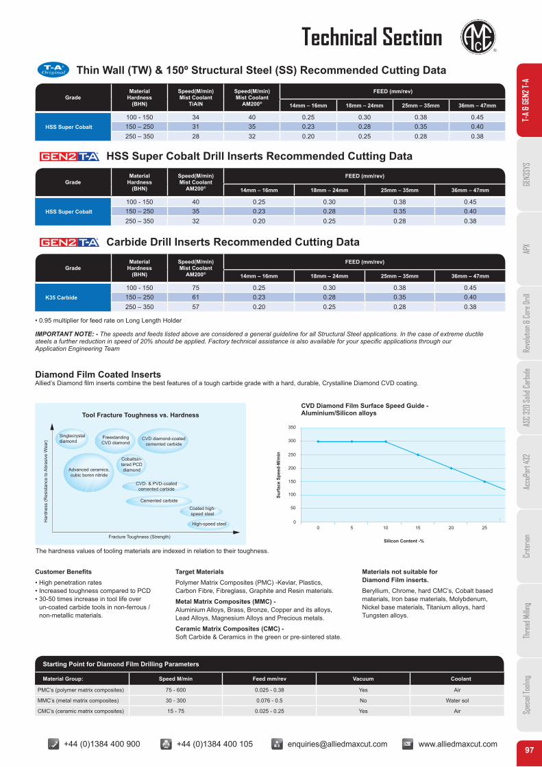
Thin Wall (TW) & 150º Structural Steel (SS) Recommended Cutting Data
HSS Super Cobalt Drill Inserts Recommended Cutting Data
Carbide Drill Inserts Recommended Cutting Data
AMEC
T-A®
Original
GradeMaterial
Hardness(BHN)
Speed(M/min)Mist Coolant
TiAlN
Speed(M/min)Mist Coolant
AM200®
FEED (mm/rev)
14mm – 16mm 18mm – 24mm 25mm – 35mm 36mm – 47mm
HSS Super Cobalt100 - 150 34 40 0.25 0.30 0.38 0.45150 – 250 31 35 0.23 0.28 0.35 0.40250 – 350 28 32 0.20 0.25 0.28 0.38
GradeMaterial
Hardness(BHN)
Speed(M/min)Mist Coolant
AM200®
FEED (mm/rev)
14mm – 16mm 18mm – 24mm 25mm – 35mm 36mm – 47mm
HSS Super Cobalt100 - 150 40 0.25 0.30 0.38 0.45150 – 250 35 0.23 0.28 0.35 0.40250 – 350 32 0.20 0.25 0.28 0.38
GradeMaterial
Hardness(BHN)
Speed(M/min)Mist Coolant
AM200®
FEED (mm/rev)
14mm – 16mm 18mm – 24mm 25mm – 35mm 36mm – 47mm
K35 Carbide100 - 150 75 0.25 0.30 0.38 0.45150 – 250 61 0.23 0.28 0.35 0.40250 – 350 57 0.20 0.25 0.28 0.38
• 0.95 multiplier for feed rate on Long Length Holder
IMPORTANT NOTE: - The speeds and feeds listed above are considered a general guideline for all Structural Steel applications. In the case of extreme ductilesteels a further reduction in speed of 20% should be applied. Factory technical assistance is also available for your specific applications through ourApplication Engineering Team
Diamond Film Coated InsertsAllied’s Diamond film inserts combine the best features of a tough carbide grade with a hard, durable, Crystalline Diamond CVD coating.
Tool Fracture Toughness vs. HardnessCVD Diamond Film Surface Speed Guide -Aluminium/Silicon alloys
Har
dnes
s (R
esis
tanc
e to
Abr
asiv
e W
ear)
Surf
ace
Spee
d-M
/min
Silicon Content -%Fracture Toughness (Strength)
350
300
250
200
150
100
50
00 5 10 15 20 25
The hardness values of tooling materials are indexed in relation to their toughness.
Customer Benefits• High penetration rates• Increased toughness compared to PCD• 30-50 times increase in tool life over
un-coated carbide tools in non-ferrous / non-metallic materials.
Target MaterialsPolymer Matrix Composites (PMC) -Kevlar, Plastics, Carbon Fibre, Fibreglass, Graphite and Resin materials.
Metal Matrix Composites (MMC) -Aluminium Alloys, Brass, Bronze, Copper and its alloys, Lead Alloys, Magnesium Alloys and Precious metals.
Ceramic Matrix Composites (CMC) -Soft Carbide & Ceramics in the green or pre-sintered state.
Materials not suitable for Diamond Film inserts.Beryllium, Chrome, hard CMC’s, Cobalt based materials, Iron base materials, Molybdenum, Nickel base materials, Titanium alloys, hard Tungsten alloys.
Singlecrystaldiamond
FreestandingCVD diamond
CVD diamond-coatedcemented carbide
Advanced ceramics,cubic boron nitride
Cobaltsin-tered PCDdiamond
CVD- & PVD-coatedcemented carbide
Cemented carbide
Coated high-speed steel
High-speed steel
Starting Point for Diamond Film Drilling Parameters
Material Group: Speed M/min Feed mm/rev Vacuum Coolant
PMC’s (polymer matrix composites) 75 - 600 0.025 - 0.38 Yes Air
MMC’s (metal matrix composites) 30 - 300 0.076 - 0.5 No Water sol
CMC’s (ceramic matrix composites) 15 - 75 0.025 - 0.25 Yes Air
+44 (0)1384 400 900 +44 (0)1384 400 105 [email protected] www.alliedmaxcut.com +44 (0)1384 400 900 +44 (0)1384 400 105 [email protected] www.alliedmaxcut.com98
Technical SectionT-
A &
GEN2
T-A
GEN3
SYS
APX
Revo
lution
& C
ore D
rill
ASC
320
Solid
Car
bide
Accu
Port
432
Crite
rion
Thre
ad M
illing
Spec
ial To
oling
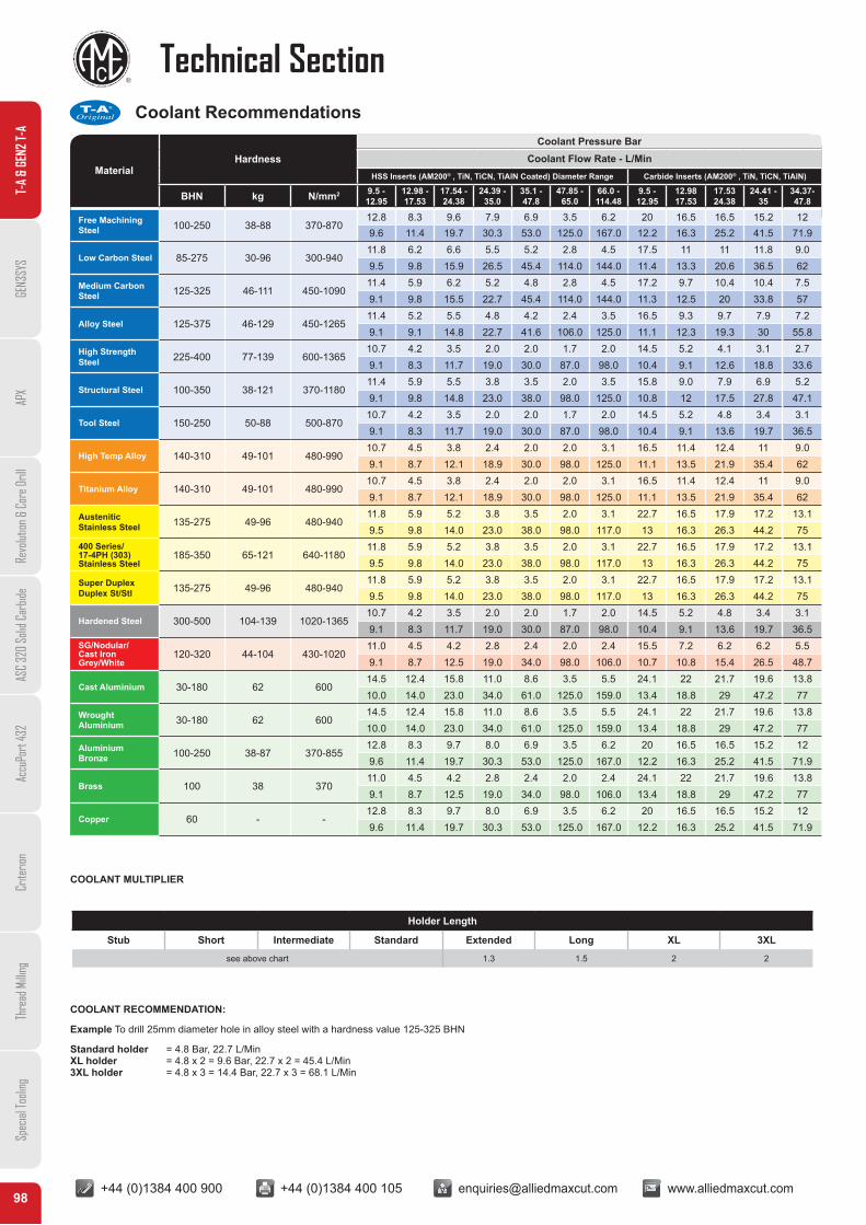
Coolant Recommendations
MaterialHardness Coolant Flow Rate - L/Min
HSS Inserts (AM200® , TiN, TiCN, TiAlN Coated) Diameter Range Carbide Inserts (AM200® , TiN, TiCN, TiAlN)
BHN kg N/mm2 9.5 -12.95
12.98 -17.53
17.54 -24.38
24.39 -35.0
35.1 -47.8
47.85 -65.0
66.0 -114.48
9.5 -12.95
12.9817.53
17.5324.38
24.41 -35
34.37-47.8
Free Machining Steel 100-250 38-88 370-870
12.8 8.3 9.6 7.9 6.9 3.5 6.2 20 16.5 16.5 15.2 129.6 11.4 19.7 30.3 53.0 125.0 167.0 12.2 16.3 25.2 41.5 71.9
Low Carbon Steel 85-275 30-96 300-94011.8 6.2 6.6 5.5 5.2 2.8 4.5 17.5 11 11 11.8 9.09.5 9.8 15.9 26.5 45.4 114.0 144.0 11.4 13.3 20.6 36.5 62
Medium Carbon Steel 125-325 46-111 450-1090
11.4 5.9 6.2 5.2 4.8 2.8 4.5 17.2 9.7 10.4 10.4 7.59.1 9.8 15.5 22.7 45.4 114.0 144.0 11.3 12.5 20 33.8 57
Alloy Steel 125-375 46-129 450-126511.4 5.2 5.5 4.8 4.2 2.4 3.5 16.5 9.3 9.7 7.9 7.29.1 9.1 14.8 22.7 41.6 106.0 125.0 11.1 12.3 19.3 30 55.8
High Strength Steel 225-400 77-139 600-1365
10.7 4.2 3.5 2.0 2.0 1.7 2.0 14.5 5.2 4.1 3.1 2.79.1 8.3 11.7 19.0 30.0 87.0 98.0 10.4 9.1 12.6 18.8 33.6
Structural Steel 100-350 38-121 370-118011.4 5.9 5.5 3.8 3.5 2.0 3.5 15.8 9.0 7.9 6.9 5.29.1 9.8 14.8 23.0 38.0 98.0 125.0 10.8 12 17.5 27.8 47.1
Tool Steel 150-250 50-88 500-87010.7 4.2 3.5 2.0 2.0 1.7 2.0 14.5 5.2 4.8 3.4 3.19.1 8.3 11.7 19.0 30.0 87.0 98.0 10.4 9.1 13.6 19.7 36.5
High Temp Alloy 140-310 49-101 480-99010.7 4.5 3.8 2.4 2.0 2.0 3.1 16.5 11.4 12.4 11 9.09.1 8.7 12.1 18.9 30.0 98.0 125.0 11.1 13.5 21.9 35.4 62
Titanium Alloy 140-310 49-101 480-99010.7 4.5 3.8 2.4 2.0 2.0 3.1 16.5 11.4 12.4 11 9.09.1 8.7 12.1 18.9 30.0 98.0 125.0 11.1 13.5 21.9 35.4 62
AusteniticStainless Steel 135-275 49-96 480-940
11.8 5.9 5.2 3.8 3.5 2.0 3.1 22.7 16.5 17.9 17.2 13.19.5 9.8 14.0 23.0 38.0 98.0 117.0 13 16.3 26.3 44.2 75
400 Series/17-4PH (303)Stainless Steel
185-350 65-121 640-118011.8 5.9 5.2 3.8 3.5 2.0 3.1 22.7 16.5 17.9 17.2 13.19.5 9.8 14.0 23.0 38.0 98.0 117.0 13 16.3 26.3 44.2 75
Super DuplexDuplex St/Stl 135-275 49-96 480-940
11.8 5.9 5.2 3.8 3.5 2.0 3.1 22.7 16.5 17.9 17.2 13.19.5 9.8 14.0 23.0 38.0 98.0 117.0 13 16.3 26.3 44.2 75
Hardened Steel 300-500 104-139 1020-136510.7 4.2 3.5 2.0 2.0 1.7 2.0 14.5 5.2 4.8 3.4 3.19.1 8.3 11.7 19.0 30.0 87.0 98.0 10.4 9.1 13.6 19.7 36.5
SG/Nodular/ Cast Iron Grey/White
120-320 44-104 430-102011.0 4.5 4.2 2.8 2.4 2.0 2.4 15.5 7.2 6.2 6.2 5.59.1 8.7 12.5 19.0 34.0 98.0 106.0 10.7 10.8 15.4 26.5 48.7
Cast Aluminium 30-180 62 60014.5 12.4 15.8 11.0 8.6 3.5 5.5 24.1 22 21.7 19.6 13.810.0 14.0 23.0 34.0 61.0 125.0 159.0 13.4 18.8 29 47.2 77
Wrought Aluminium 30-180 62 600
14.5 12.4 15.8 11.0 8.6 3.5 5.5 24.1 22 21.7 19.6 13.810.0 14.0 23.0 34.0 61.0 125.0 159.0 13.4 18.8 29 47.2 77
Aluminium Bronze 100-250 38-87 370-855
12.8 8.3 9.7 8.0 6.9 3.5 6.2 20 16.5 16.5 15.2 129.6 11.4 19.7 30.3 53.0 125.0 167.0 12.2 16.3 25.2 41.5 71.9
Brass 100 38 37011.0 4.5 4.2 2.8 2.4 2.0 2.4 24.1 22 21.7 19.6 13.89.1 8.7 12.5 19.0 34.0 98.0 106.0 13.4 18.8 29 47.2 77
Copper 60 - -12.8 8.3 9.7 8.0 6.9 3.5 6.2 20 16.5 16.5 15.2 129.6 11.4 19.7 30.3 53.0 125.0 167.0 12.2 16.3 25.2 41.5 71.9
Coolant Pressure Bar
COOLANT MULTIPLIER
Holder Length
Stub Short Intermediate Standard Extended Long XL 3XL
see above chart 1.3 1.5 2 2
COOLANT RECOMMENDATION:
Example To drill 25mm diameter hole in alloy steel with a hardness value 125-325 BHN
Standard holder = 4.8 Bar, 22.7 L/MinXL holder = 4.8 x 2 = 9.6 Bar, 22.7 x 2 = 45.4 L/Min3XL holder = 4.8 x 3 = 14.4 Bar, 22.7 x 3 = 68.1 L/Min
AMEC
T-A®
Original
+44 (0)1384 400 900 +44 (0)1384 400 105 [email protected] www.alliedmaxcut.com +44 (0)1384 400 900 +44 (0)1384 400 105 [email protected] www.alliedmaxcut.com99
Technical Section
T-A
& GE
N2 T-
AGE
N3SY
SAP
XRe
volut
ion &
Cor
e Dril
lAS
C 32
0 So
lid C
arbid
eAc
cuPo
rt 43
2Cr
iterio
nTh
read
Milli
ngSp
ecial
Tooli
ng
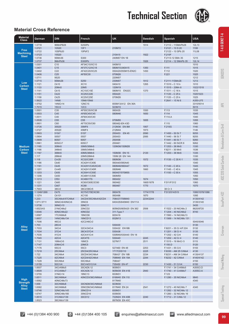
Material Cross ReferenceMaterialClass German DIN French UK Swedish Spanish USA
FreeMachining
Steel
1.0718 96MnPB28 S250Pb 1914 F.2112 – 11SMnPb28 12L131.0721 10S20 10F1 210M15 F.2121 – 10 S 20 11081.0722 10SPb20 10PbF2 F.2122 – 10 SPb 20 11L081.0723 15S20 210A15 1922 F.210F 1.0736 9SMn36 S300 240M07 EN 1B F.2113-12 SMn 35 12151.0737 9MnPb36 S300Pb 1926 F.2114 – 12 SMnPb 35 12L14
LowCarbonSteel
1.0301 C10 AF34C10/XC10 045M10 10101.0401 C15 AF37C12/XC18 080M15;040A15 1350 F.111 10151.0402 C22 AF42C20/XC25 050A20/055M15-EN2C 1450 F.112 10201.0406 C25 AF50C30 070M26 F.221 10251.0711 9S20 220M07 12121.0715 9SMn28 S250 230M07 1912 F.2111-11SMn28 12131.1121 Ck10 XC10 040A10 1265 F.1510 – C 10 k 10101.1133 20Mn5 20M5 120M19 F.1515 – 20Mn 6 1022/15181.1141 Ck15 XC15/C15E 080M15 EN32C 1370 F.1511 – C 16 k 10151.1151 Ck22 XC25/C22E 050A20 F.1120 – C 25 k 102010231.1158 Ck25 XC25/C25E 070M26 F.1120 – C 25 k 10251.5622 14Ni6 15N6/15Ni6 F.2641 – 15 Ni 6 A350-LF51.5752 14NiCr14 12NC15 655M13/A12 EN 36A 3310/93141.7015 15Cr3 12C3 523M15 5015
MediumCarbonSteel
1.0501 C35 AF55C35/XC38 060A35 1550 F.113 10351.0503 C45 AF65C45/C45 080M46 1650 F.114 10451.0511 C40 AF60C40/C40 F.114.A 10401.0535 C55 C55 070M55 1655 10551.0601 C60 AF70C55/C60 080A62-EN 43D F.115 10601.0726 35S20 35MF6 212M36 EN 8M 1957 F.210G 11401.0727 45S20 45MF4 212M44 1973 11461.0903 51Si7 51S7 250A53 EN 45 2090 F.1450 – 50 Si 7 92551.0904 55Si7 55S7 250A53 2085 F.1440 – 56 Si 7 92551.0909 60Si7 60S7 250A58 F.1441 – 60 Si 7 92601.0961 60SiCr7 60SC7 250A61 F.1442 – 60 SiCR 8 92621.1165 30Mn5 35M5/30Mn5 120M36/150M28 F.1203 – 36 Mn5 13301.1166 34Mn5 35M5/34Mn5 F.8211 – 30 Mn5 15361.1167 36Mn5 40M5/36Mn5 150M36 EN 15 2120 F.1203 – 36 Mn5 13351.117 28Mn6 20M5/28Mn6 150M 28 EN 14A 13301.118 Cm35 XC32/C35R 080M36 1572 F.1135 – C 35 K-1 10351.1186 Ck40 XC42H1/C40E 060A40/080A40 10401.1191 Ck45 XC42H1/C45/XC45 080M46/060A47 1672 F.1140 – C 45 k 10451.1201 Cm45 XC42H1/C45R 080M46 1660 F.1145 – C 45 k 10451.1203 Ck55 XC55H1/C55E 060A57/070M55 F.1150 – C 55 k 10551.1206 Ck50 XC48H1/C50E 080M50 10501.1213 Cf53 XC48H1TS 060A52 1674 10501.1221 Ck60 XC60/C60E/2C60 060A62 1665/1678 F.511/F.512 10601.1231 Ck67 XC68 060A67 1770 10701.7003 38Cr2 38C2/38Cr5 38 Cr 3
AlloySteel
1.1248/1269 Ck75 XC75/C75E/XC90 060A78 1774/1778 F.513/514/515 1080/1078/10861.1274 Ck101 XC100 060A96 1870 10951.233 35CrMo4/47CrMo4 34CD4/35CrMo4/42CD4 708A37/708M40 2234/2244 4135/41421.571/.5711 36NiCr6/40NiCr6 35NC6 640A35/640M40 EN111A 3135/31401.5736 36NiCr10 30NC11 34351.6523/43 21NiCrMo2 20NCD2 805M20/805A20 EN 362 2506 F.1522 – 20 NiCrMo 2 8620/87201.6546 40NiCrMo22 40NCD2 311-Type 7 F.1204 – 40 NiCrMo2 87401.6587 17CrNiMo8 18NCD6 820A16 F.1560 – 14 NiCrMo13 1.6657 14NiCrMo134 16NCD13 832M13 F.1569 – 14 NiCrMo 131 1.7006 46Cr2 42C2/46Cr2 5045/50461.703 28Cr4 530A30 51301.7033 34Cr4 32C4/34Cr4 530A32 EN18B F.8221 – 35 Cr 4/F.224 51321.7034 37Cr4 38C4/37Cr4 530A36 F.1201 – 38 Cr 4 51351.7035 41Cr4 42C4/41Cr4 530M40/530A40 EN 18 F.1202 – 42 Cr4 51401.7045 42Cr4 42C4TS 530A40 2245 F.1202 – 42 Cr 4 51401.7131 16MnCr5 16MC5 527M17 2511 F.1515 – 16 MnCr 5 51151.7147 20MnCr5 20MC5 F.150.D 51201.7176 55Cr3 55C3 527A60 EN 48 2253 F.1431 – 55 Cr3 51551.7218 25CrMo4 25CD4/25CrMo4 1717CDS110 2225 F.8330 – AM 25 CrMo4 41301.722 34CrMo4 35CD4/34CrMo4 708A37 EN 19B 2234 F.8231 – AM 34 CrMo4 4135/41371.7225 42CrMo4 42CD4/42CrMo4 708M40 EN 19A 2244 F.8232 – 42 CrMo4 4140/41421.7228 50CrMo4 50CrMo4 708A47 41501.8159 50CrV4 50CV4/51CrV4 735A50 EN 47 2230 F.1430 – 51 CrV4 6150
HighStrength
AlloySteel
1.8507 34CrAIMo5 30CAD6.12 905M31 F.1741 – 34 CrAIMo5 A355CI.D1.8509 41CrAIMo7 40CAD6.12 905M39 EN 41B 2940 F.1740 – 41 CrAIMo7 A355CI.A1.5755 31NiCr14 18NC13 653M31 F.123 1.6511 36CrNIMo4 40NCD3/36CrNiMo4 816M40 EN 110 F.1280 – 35 NiCrMo4 98401.6562 40NiCrMo73 817M40 43401.658 30CrNiMo8 30CND8/30CrNiMo8 823M30 1.6582 34CrNiMo8 35NCD6/34CrNiMo6 817M40 EN 24 2541 F.1272 – 40 NiCrMo 7 43401.6746 32NiCrMo145 35NCD14 830M31 F.1262 – 32 NiCrMo 12 1.6747 30NiCrMo166 35NCD16 835M30 F.1260 – 32 NiCrMo 16 1.8515 31CrMoV139 30CD12 722M24 EN 40B 2240 F.1712 – 31 CrMo 12 1.8523 39CrMoV139 897M39 EN 40C
+44 (0)1384 400 900 +44 (0)1384 400 105 [email protected] www.alliedmaxcut.com +44 (0)1384 400 900 +44 (0)1384 400 105 [email protected] www.alliedmaxcut.com100
Technical SectionT-
A &
GEN2
T-A
GEN3
SYS
APX
Revo
lution
& C
ore D
rill
ASC
320
Solid
Car
bide
Accu
Port
432
Crite
rion
Thre
ad M
illing
Spec
ial To
oling
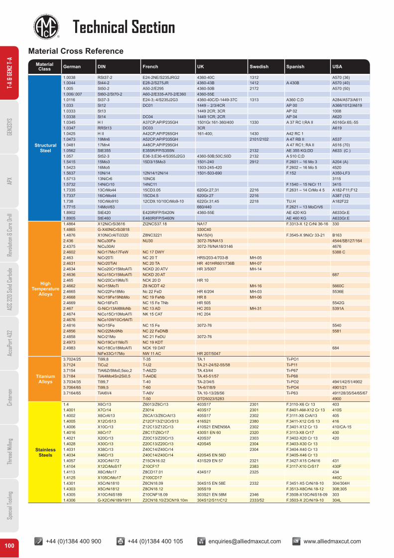
Material Cross ReferenceMaterialClass German DIN French UK Swedish Spanish USA
StructuralSteel
1.0038 RSt37-2 E24-2NE/S235JRG2 4360-40C 1312 A570 (36)1.0044 St44-2 E28-2/S275JR 4360-43B 1412 A 430B A570 (40)1.005 St50-2 A50-2/E295 4360-50B 2172 A570 (50)1.006/.007 St60-2/St70-2 A60-2/E335-A70-2/E360 4360-55E1.0116 St37-3 E24-3;-4/S235J2G3 4360-40C/D-1449-37C 1313 A360 C;D A284/A573/A6111.033 St12 DC01 1449 – 2/3/4CR AP 00 A366/1012/A6191.0333 St13 1449 2CR; 3CR AP 02 10081.0338 St14 DC04 1449 1CR; 2CR AP 04 A6201.0345 H I A37CP;AP/P235GH 1501Gr.161-360/400 1330 A 37 RC I;RA II A516Gr.65;-551.0347 RRSt13 DC03 3CR A6191.0425 H II A42CP;AP/P265GH 161-400; 1430 A42 RC 11.0473 19Mn6 A52CP;AP/P335GH 2101/2102 A 47 RB II A5371.0481 17Mn4 A48CP;AP/P295GH A 47 RC1; RA II A516 (70)1.0562 StE355 E355R/FP/S355N 2132 AE 355 KG;DD A633 (C )1.057 St52-3 E36-3;E36-4/S355J2G3 4360-50B;50C;50D 2132 A 510 C;D1.5415 15Mo3 15D3/15Mo3 1501-240 2912 F.2601 – 16 Mo 3 A204 (A)1.5423 16Mo5 1503-245-420 F.2602 – 16 Mo 5 45201.5637 10Ni14 12N14/12Ni14 1501-503-690 F.152 A350-LF31.5713 13NiCr6 10NC6 31151.5732 14NiCr10 14NC11 F.1540 – 15 NiCr 11 34151.7335 13CrMo44 15CD3.05 620Gr.27;31 2216 F.2631 – 14 CrMo 4 5 A182-F11;F121.7337 16CrMo44 15CD4.5 620Gr.27 2216 A387 (12)1.738 10CrMo910 12CD9.10/10CrMo9-10 622Gr.31;45 2218 TU.H A182F221.7715 14MoV63 660/440 F.2621 – 13 MoCrV61.8902 StE420 E420RIFP/S420N 4360-55E AE 420 KG A633Gr.E1.8905 StE460 E460RIFP/S460N AE 460 KG A633Gr.E
HighTemperature
Alloys
1.4864 X12NiCrSi3616 ZI2NCS37.18 NA17 F.3313-X 12 CrNi 36-16 3301.4865 G-X40NiCrSi3818 330C401.4876 X10NiCrAITi3320 Z8NC3221 NA15(H) F.3545-X 9NiCr 33-21 B1632.436 NiCu30Fe NU30 3072-76/NA13 4544/SB127/1642.4375 NiCu30AI 3072-76/NA18/3146 46762.4602 NiCr17Mo17FeW NC 17 DWY 5388 C2.463 NiCr20Ti NC 20 T HR5/203-4/703-B MH-052.4631 NiCr20TiAI NC 20 TA HR 401HR601/736B MH-072.4634 NiCo20Cr15MoAITi NCKD 20 ATV HR 3/5007 MH-142.4636 NiCo15Cr15MoAITi NCKD 20 AT 6872.465 NiCr20Co19MoTi NCK 20 D HR 102.4662 NiCr15MoTi Z8 NCDT 42 MH-16 5660C2.4665 NiCr22Fe18Mo Nc 22 FeD HR 6/204 MH-03 5536E2.4668 NiCr19Fe19NbMo NC 19 FeNb HR 8 MH-062.4669 NiCr16FeTi NC 15 Fe TNb HR 505 5542G2.467 G-NiCr13AI6MoNb NC 13 AD HC 203 MH-31 5391A2.4674 NiCo15Cr10MoAITi NK 15 CAT HC 2042.4676 NiCo10W10Cr9AITi2.4816 NiCr15Fe NC 15 Fe 3072-76 55402.4856 NiCr22Mo9Nb NC 22 FeDNB 55812.4858 NiCr21Mo NC 21 FeDU 3072-762.4973 NiCr19Co11MoTi NC 19 KDT2.4983 NiCr18Co18MoAlTi NCK 19 DAT 684
NiFe33Cr17Mo NW 11 AC HR 207/5047
TitaniumAlloys
3.7024/25 Ti99,8 T-35 TA.1 Ti-PO13.7124 TiCu2 T-U2 TA.21-24/52-55/58 Ti-P113.7154 TiAl6Zr5Mo0,5sio,2 T-A6ZD TA.43/44 Ti-P673.7184 TiAl4Mo4Sn2Si0,5 T-A4DE TA.45-51/57 Ti-P683.7034/35 Ti99,7 T-40 TA-2/34/5 Ti-PO2 4941/42/51/49023.7064/65 Ti99,5 T-60 TA-6/7/8/9 Ti-PO4 4901/213.7164/65 TiAI6V4 T-A6V TA.10-13/28/56 Ti-P63 491128/35/54/65/67
T-50 DTD5023/5283 4900
StainlessSteels
1.4 X6Cr13 Z6013/Z6Cr13 403S17 2301 F.3110-X6 Cr 13 4031.4001 X7Cr14 Z3014 403S17 2301 F.8401-AM-X12 Cr 13 410S1.4002 X6CrAI13 Z6CA13/Z6CrAI13 405S17 2302 F.3111-X6 CrAl13 4051.4005 X12CrS13 Z12CF13/Z12CrS13 416S21 2380 F.3411-X12 CrS 13 4161.4006 X10Cr13 Z12C13/Z12Cr13 410S21 ENEN56A 2302 F.3401-X12 Cr 13 410/CA-151.4016 X6Cr17 Z8C17/Z6Cr17 430S1 EN 60 2320 F.3113-X8 Cr17 4301.4021 X20Cr13 Z20C13/Z20Cr13 420S37 2303 F.3402-X20 Cr 13 4201.4028 X30Cr13 Z20C13/Z20Cr13 420S45 2304 F.3403-X30 Cr 131.4031 X38Cr13 Z40C14/Z40Cr14 2304 F.3404-X40 Cr 131.4034 X46Cr13 Z40C14/Z40Cr14 420S45 EN 56D F.3405-X46 Cr 131.4057 X20CrNi172 Z15CN16.02 431S29 EN 57 2321 F.3427-X15 CrNi16 4311.4104 X12CrMoS17 Z10CF17 2383 F.3117-X10 CrS17 430F1.4113 X6CrMo17 Z8CD17.01 434S17 2325 4341.4125 X105CrMo17 Z100CD17 440C1.4301 X5CrNi1810 Z6CN18.09 304S15 EN 58E 2332 F.3451-X5 CrNi18-10 304/304H1.4303 X5CrNi1812 Z8CN18.12 305S19 F.3513-X8CrNi.18-12 308;3051.4305 X10CrNiS189 Z10CNF18.09 303S21 EN 58M 2346 F.3508-X10CrNiS18-09 3031.4306 G-X2CrNi189/1911 Z2CN18.10/Z3CN19.10m 304S12/S11/C12 2333/52 F.3503-X 2CrNi19-10 304L
+44 (0)1384 400 900 +44 (0)1384 400 105 [email protected] www.alliedmaxcut.com +44 (0)1384 400 900 +44 (0)1384 400 105 [email protected] www.alliedmaxcut.com101
Technical Section
T-A
& GE
N2 T-
AGE
N3SY
SAP
XRe
volut
ion &
Cor
e Dril
lAS
C 32
0 So
lid C
arbid
eAc
cuPo
rt 43
2Cr
iterio
nTh
read
Milli
ngSp
ecial
Tooli
ng
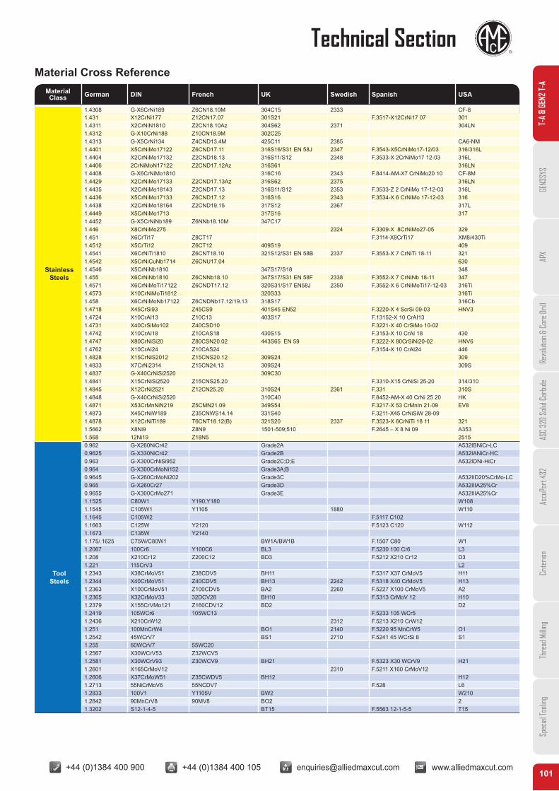
Material Cross ReferenceMaterialClass German DIN French UK Swedish Spanish USA
StainlessSteels
1.4308 G-X6CrNi189 Z6CN18.10M 304C15 2333 CF-81.431 X12CrNi177 Z12CN17.07 301S21 F.3517-X12CrNi17 07 3011.4311 X2CrNiN1810 Z2CN18.10Az 304S62 2371 304LN1.4312 G-X10CrNi188 Z10CN18.9M 302C251.4313 G-X5CrNi134 Z4CND13.4M 425C11 2385 CA6-NM1.4401 X5CrNiMo17122 Z6CND17.11 316S16/S31 EN 58J 2347 F.3543-X5CrNiMo17-12/03 316/316L1.4404 X2CrNiMo17132 Z2CND18.13 316S11/S12 2348 F.3533-X 2CrNiMo17 12-03 316L1.4406 2CrNiMoN17122 Z2CND17.12Az 316S61 316LN1.4408 G-X6CrNiMo1810 316C16 2343 F.8414-AM-X7 CrNiMo20 10 CF-8M1.4429 X2CrNiMo17133 Z2CND17.13Az 316S62 2375 316LN1.4435 X2CrNiMo18143 Z2CND17.13 316S11/S12 2353 F.3533-Z 2 CrNiMo 17-12-03 316L1.4436 X5CrNiMo17133 Z6CND17.12 316S16 2343 F.3534-X 6 CrNiMo 17-12-03 3161.4438 X2CrNiMo18164 Z2CND19.15 317S12 2367 317L1.4449 X5CrNiMo1713 317S16 3171.4452 G-X5CrNiNb189 Z6NNb18.10M 347C171.446 X8CrNiMo275 2324 F.3309-X 8CrNiMo27-05 3291.451 X6CrTi17 Z8CT17 F.3114-X8CrTi17 XM8/430Ti1.4512 X5CrTi12 Z6CT12 409S19 4091.4541 X6CrNiTi1810 Z6CNT18.10 321S12/S31 EN 58B 2337 F.3553-X 7 CrNiTi 18-11 3211.4542 X5CrNiCuNb1714 Z6CNU17.04 6301.4546 X5CrNiNb1810 347S17/S18 3481.455 X6CrNiNb1810 Z6CNNb18.10 347S17/S31 EN 58F 2338 F.3552-X 7 CrNiNb 18-11 3471.4571 X6CrNiMoTi17122 Z6CNDT17.12 320S31/S17 EN58J 2350 F.3552-X 6 CrNiMoTi17-12-03 316Ti1.4573 X10CrNiMoTi1812 320S33 316Ti1.458 X6CrNiMoNb17122 Z6CNDNb17.12/19.13 318S17 316Cb1.4718 X45CrSi93 Z45CS9 401S45 EN52 F.3220-X 4 ScrSi 09-03 HNV31.4724 X10CrAI13 Z10C13 403S17 F.13152-X 10 CrAI131.4731 X40CrSiMo102 Z40CSD10 F.3221-X 40 CrSiMo 10-021.4742 X10CrAI18 Z10CAS18 430S15 F.3153-X 10 CrAI 18 4301.4747 X80CrNiSi20 Z80CSN20.02 443S65 EN 59 F.3222-X 80CrSiNi20-02 HNV61.4762 X10CrAI24 Z10CAS24 F.3154-X 10 CrAI24 4461.4828 X15CrNiS2012 Z15CNS20.12 309S24 3091.4833 X7CrNi2314 Z15CN24.13 309S24 309S1.4837 G-X40CrNiSi2520 309C301.4841 X15CrNiSi2520 Z15CNS25.20 F.3310-X15 CrNiSi 25-20 314/3101.4845 X12CrNi2521 Z12CN25.20 310S24 2361 F.331 310S1.4848 G-X40CrNiSi2520 310C40 F.8452-AM-X 40 CrNi 25 20 HK1.4871 X53CrMnNiN219 Z5CMN21.09 349S54 F.3217-X 53 CrMnIn 21-09 EV81.4873 X45CrNiW189 Z35CNWS14.14 331S40 F.3211-X45 CrNiSiW 28-091.4878 X12CrNiTi189 T6CNT18.12(B) 321S20 2337 F.3523-X 6CrNiTi 18 11 3211.5662 X8Ni9 Z8N9 1501-509;510 F.2645 – X 8 Ni 09 A3531.568 12Ni19 Z18N5 2515
ToolSteels
0.962 G-X260NiCr42 Grade2A A532IBNiCr-LC0.9625 G-X330NiCr42 Grade2B A532IANiCr-HC0.963 G-X300CrNiSi952 Grade2C;D;E A532IDNi-HiCr0.964 G-X300CrMoNi152 Grade3A;B0.9645 G-X260CrMoNi202 Grade3C A532IID20%CrMo-LC0.965 G-X260Cr27 Grade3D A532IIIA25%Cr0.9655 G-X300CrMo271 Grade3E A532IIIA25%Cr1.1525 C80W1 Y190;Y180 W1081.1545 C105W1 Y1105 1880 W1101.1645 C105W2 F.5117 C1021.1663 C125W Y2120 F.5123 C120 W1121.1673 C135W Y21401.175/.1625 C75W/C80W1 BW1A/BW1B F.1507 C80 W11.2067 100Cr6 Y100C6 BL3 F.5230 100 Cr6 L31.208 X210Cr12 Z200C12 BD3 F.5212 X210 Cr12 D31.221 115CrV3 L21.2343 X38CrMoV51 Z38CDV5 BH11 F.5317 X37 CrMoV5 H111.2344 X40CrMoV51 Z40CDV5 BH13 2242 F.5318 X40 CrMoV5 H131.2363 X100CrMoV51 Z100CDV5 BA2 2260 F.5227 X100 CrMoV5 A21.2365 X32CrMoV33 32DCV28 BH10 F.5313 CrMoV 12 H101.2379 X155CrVMo121 Z160CDV12 BD2 D21.2419 105WCr6 105WC13 F.5233 105 WCr51.2436 X210CrW12 2312 F.5213 X210 CrW121.251 100MnCrW4 BO1 2140 F.5220 95 MnCrW5 O11.2542 45WCrV7 BS1 2710 F.5241 45 WCrSi 8 S11.255 60WCrV7 55WC201.2567 X30WCrV53 Z32WCV51.2581 X30WCrV93 Z30WCV9 BH21 F.5323 X30 WCrV9 H211.2601 X165CrMoV12 2310 F.5211 X160 CrMoV121.2606 X37CrMoW51 Z35CWDV5 BH12 H121.2713 55NiCrMoV6 55NCDV7 F.528 L61.2833 100V1 Y1105V BW2 W2101.2842 90MnCrV8 90MV8 BO2 21.3202 S12-1-4-5 BT15 F.5563 12-1-5-5 T15

+44 (0)1384 400 900 +44 (0)1384 400 105 [email protected] www.alliedmaxcut.com +44 (0)1384 400 900 +44 (0)1384 400 105 [email protected] www.alliedmaxcut.com102
Technical SectionT-
A &
GEN2
T-A
GEN3
SYS
APX
Revo
lution
& C
ore D
rill
ASC
320
Solid
Car
bide
Accu
Port
432
Crite
rion
Thre
ad M
illing
Spec
ial To
oling
Material Cross ReferenceMaterialClass German DIN French UK Swedish Spanish USA
ToolSteels
1.3207 S10-4-3-10 Z130WKCDV10-10-04-03 F.553 10-4-3-101.3243 S6-5-2-5 Z85WDKCV06-05-05-04-02 2723 F.5613 6-5-2-51.3246 S7-4-2-5 Z110WKCDV07-05-04-04-02 F.5613 6–5-2-5 M411.3247 S2-10-1-8 Z110DKCWV09-08-04-02-01 BT42 F.5615 7-4-2-5 M421.3249 S2-9-2-8 BM34 F.5611 2-9-2-8 M33/M341.3255 S18-1-2-5 Z80WKCV18-05-04-01 BT4 F.5530 18-1-1-5 T41.3265 S18-1-2-10 BT5 F.5540 18-0-2-10 T51.3342 SC6-5-2 Z90WDCV06-05-04-03 M31.3343 S6-5-2 Z85WDCV06-05-04-02 BM2 2722 F.5603 6-5-2 M21.3344 S6-5-3 Z130WDCV06-05-04-04 F.5605 6-5-3 M3Class21.3346 S2-9-1 Z85DCWV08-04-02-01 BM1 H41/M11.3348 S2-9-2 Z100DCWV09-04-02-02 2782 F.5607 2-9-2 M71.3355 S18-0-1 Z80WCV18-04-01 BT1 F.5520 18-0-1 T11.3401 X120Mn12 Z120M12/Z120Mn12 F.82551-AM-X 120 Mn 12 A128(A)1.3505 100Cr6 100C6 534A99 2258 F.1310 – 100 Cr 6 52100
HardenedSteel HARDOX 400/500/600
CastAluminium
3.2151 G-AISi6Cu4 A-S5U LM4-LM22 4230 L-2660 3,1923.2161 G-AISi8Cu3 A-S9U3 LM24 4252 L-2630 3,8013.2341 G-AISi5Mg A-S4G DTD716B3.2371 G-AISi7Mg A-S7GO,3 2L99/LM25 4244 A356.23.2373 G-AISi9Mg A7-S10G 42533.2381 G-AISi10Mg A-S10G LM9 4253 L-2560 A3603.2583 G-AISi12Cu A-S12U LM20 4260 L-2530 4,1313.3561 G-AIMg5 A-G6 LM5 5,1413.3581 G-AISi12 A-S13 LM6 4261 L-2520 A4133.3591 G-AIMg10 A-G10-Y4 LM10 L-2310 520
AlSi17Cu4 390AlSi18-25CuNiMg LM28/LM29 393
WroughtAluminium
3.0205 Al99 A4 1C 144010 L-3001 12003.0255 Al99,5 A5 1B 144007 L-3051 1050A3.0257 E-Al A5/L 1E 144008 L-3052 1350A3.0275 Al99,7 A7 144005 L-3071 1070A3.0285 Al99,8 A8 1A 144004 L-3081 1080A3.0385 Al99,98R A99 1 11993.0505 AlMn0,5Mg0,5 N31 31053.0525 AlMn1Mg0,5 A-M1G0,5 30053.0526 AlMnMg1 A-M1G N4 L-3820 30043.0915 AlFeSi A-FeS 8011A3.1255 AlCuSiMn A-U4SG H15 144338 L-3130 20143.1305 AlCu2,5Mg0,5 A-U2G 3L86/HR13 L-3180 21173.1325 AlCuMg1 A-U4G H14 L-3120 2017A3.1355 AlCuMg2 A-U4G1 2L98 L-3140 20243.1645 AlCuMgPb A-U4Pb 144335 L-3121 20033.1655 AlCuBiPb A-U5PbBi FC1 144355 L-3182 20113.2305 E-AlMgSi 91E L-3431 6101B3.2307 Al99,85MGs1 A85-GS BTR6 64633.2315 Al-Si1 Mg A-SGMO,7 H30 144212 L-3451 61813.3206 AlMGSi0,5 H9 144103 L-3441 60603.3207 E-AlMgSi0,5 A-GS/L BTRE6 144102 6101C3.3315 AlMg1 A-GO,6 N41 144106 L-3350 5005A3.3316 AlMg1,5 A-G1,5 3L44 L-3380 5050B3.3345 AlMg4,5 50823.3523 AlMg2,5 A-G2,5C N5Mg3,5 144120 L-3360 50523.3525 AlMg2Mn0,3 A-G2M N4 52513.3535 AlMg3 A-G3M 144133 L-3390 57543.3537 AlMg2,7Mn A-G2,5MC N51 54543.3547 AlMg4,5Mn 5083 N8 144140 L-3321 50833.3555 AlMg5 N6 144146 L-3320 5056A3.4335 AlZn4,5Mg1 A-Z5G H17 144425 L-3741 70203.4345 AlZnMgCu0,5 A-Z5Gu0,6 70223.4365 AlZnMgCu1,5 A-Z5GU 2L95 L-3710 7075
SG/NodularCast Iron
0.704 GGG-40 FGS-400-12 420/12 0717-02 60-40-180.7043 GGG-40.3 FGS370-17 370/17 0717-150.705 GGG-50 FGS500-7 500/7 0727-02 65-45-120.706 GGG-60 FGS 600-3 600/3 0732-03 80-55-060.707 GGG-70 FGS 700-2 700/2 0737-01 100-70-030.708 GGG-80 FGS 800-2 800/2 120-90-020.8035 GTW-35-04 MB 35-7 W 340/30.804 GTW-40-05 MB 40-10 W 410/40.8045 GTW-45-070.8135 GTS-35-10 MN 35-10 B 340/12 SIS 08 15-00 325100.8145 GTS-45-06 MP 50-5 P 440/7 SIS 08 54-000.8155 GTS-55-04 MP 60-3 P 540/5 SIS 08 56-000.8165 GTS-65-02 SIS 08 62-030.817 GTS 70-02 MP 70-2 P 690/2 SIS 08 62-03 70 003

+44 (0)1384 400 900 +44 (0)1384 400 105 [email protected] www.alliedmaxcut.com +44 (0)1384 400 900 +44 (0)1384 400 105 [email protected] www.alliedmaxcut.com103
Technical Section
T-A
& GE
N2 T-
AGE
N3SY
SAP
XRe
volut
ion &
Cor
e Dril
lAS
C 32
0 So
lid C
arbid
eAc
cuPo
rt 43
2Cr
iterio
nTh
read
Milli
ngSp
ecial
Tooli
ng
Material Cross ReferenceMaterialClass German DIN French UK Swedish Spanish USA
Grey/WhiteCast Iron
0.6025 GG25 Ft25D/FGL250 Grade 260 0125-00 FG 25 A48-40B0.601 GG10 Ft10D/FGL100 0110-00 FG 10 A48-20B0.6015 GG15 Ft15D/FGL150 Grade 150 0115-00 FG 15 A48-25B0.602 GG20 Ft20D-FGL200 Grade 220 0120-00 FG20 A48-30B0.603 GG30 Ft30D/FGL300 Grade 300 0130-00 FG 30 A48-45B0.6035 GG35 Ft35D/FGL350 Grade 350 0135-00 FG35 A48-50B0.604 GG40 Ft40D/FGL400 Grade 400 0140-00 A48-60B
BronzeAluminium-
BronzeTin Bronze
2.0918 CuAl5As CuAl6 C 60 8002.092 CuAl8 CuAl8 C 61 0002.0932 CuAl8Fe3 CuAl7Fe2 CA 106 C 61 4002.0936 CuAl10Fe3Mn2 CuAl9Fe3Mn2 CA 105 C 62 3002.094 CuA/10Fe CuAl9Fe3 AB 1 C 95 2002.094 G-FeA/BzF50 CuAl9Fe3 AB 1 B 5052.096 CuAl9Mn2 CuAl9Mn22.0966 CuA/10Ni5Fe4 CuAl9Ni5Fe3Mn CA 104 C 63 2002.097 G-NiABzF50 CuAl9Ni5Fe AB 2 C 95 8002.0978 CuAl11NiFe5 CuAl11Ni5Fe52.1188 G-CuPb20Sn CuPb20Sn5 LB5 C 94100
Brass
2.022/2.032 CuZn5 CuZn5 CZ 125/101 C 21000/345002.034 G-CuZn37Pb CuZn40-Y30 PCB 3 C 857002.036/2.041 CuZn40/44Pb2 CuZn40/44Pb2 CZ 109/CZ130 C 28000/385002.046 CuZn20Al2 CuZn22Al2 CZ 110 C 687002.047 CuZn28Sn1 CZ 111 C 443002.053 CuZn38Sn1 CZ 112 C 464002.055 CuZn40Al2 CZ 114 C 674002.0591 G-CuZn38Al PCB1, DCB 3 C 864002.0592 G-CuZn35Al1 CuZn40-Y30 HTB 1 C 864002.0596 G-CuZn34Al2 C 862002.0598 G-CuZn25Al5 HTB 3 C 863002.105 G-CuSn10Zn G1 C 905002.1052 G-CuSn12 CuSn12 Pb2 C 908002.106 G-CuSn12Ni CT2 C 917002.1086 G-CuSn10 CT1 C 902502.109 G-CuSn7ZnPb CuSn7Pb6Zn4 C 932002.1093 G-CuSn6ZnNi LG4 C 924102.1096 G-CuSn5ZnPb/RG5 CuPb5Sn5Zn5 LG2 C 836002.1176 G-CuPb10Sn CuPb10Sn10 LB2 C 937002.1182 G-CuPb15Sn LB1 C 938002.1293 CuCrZr CC 102 C 18100
CopperCopper/NickelAlloys
2.0815 G-CuNi10 C 962002.083 CuNi25 CiNi25 CN 105 C 713002.0835 G-CuNi30 CN 2 C 964002.0842 CuNi44Mn1 CuNi44 C 721502.0872 CuNi10Fe1Mn CuNi10Fe1Mn CN 102 C 706002.0882 CuNi30Mn1Fe CuNi30Mn1Fe CN 107 C 715002.1245 CuBe1,7 CuBe1,7 CB 101 C 170002.1247 CuBe2 CuBe1,9 C 172002.1285 CuCo2Be C112 C 175002.131 CuFe2P C 19400
CuNi9Sn2 C 72500CuNi30Fe2Mn2 CuNi30Fe2Mn2 CN 108 C 71640
2.004 OF-Cu Cu-c1/C2 Cu-OF C 103/110 OF2.006 E-Cu57 Cu-a1/A2 Cu-ETP-2 C 101 C 110002.0065 E-Cu58 Cu-a1 Cu-ETP-2 C 101 C 110002.007 Se-Cu C 103002.0076 SW-Cu Cu-b2 C 12002.009 SF-Cu Cu-b1 Cu-DHP C 106 C 122002.1191 Cu-Ag 0,1P C 107002.1203 Cu-AG 0,1 CuAg-4 C 11600
PSteel
N/mm2
MStainless Steel
N/mm2
KCast and Ductile Iron
N/mm2
NNon-ferrous Material
N/mm2
SHigh Temperature Materials
N/mm2
HHardened Materials
N/mm2
<1365 <940 <1020 <855 <990 <1365

+44 (0)1384 400 900 +44 (0)1384 400 105 [email protected] www.alliedmaxcut.com +44 (0)1384 400 900 +44 (0)1384 400 105 [email protected] www.alliedmaxcut.com104
T-A
& GE
N2 T-
AGE
N3SY
SAP
XRe
volut
ion &
Cor
e Dril
lAS
C 32
0 So
lid C
arbid
eAc
cuPo
rt 43
2Cr
iterio
nTh
read
Milli
ngSp
ecial
Tooli
ng
Technical Section
Accelerated corner wear 2,6,7
Spiral or large diameter at hole start 1,2,3,4,27 2,6,7,27 2,4,8,27 10,26,27
Insert Chipping 2,4,8,9 8,9,10,26
Blue Chips
Built Up Edge (BUE)
Chatter 1,2,3,4,27 1,3,4,5 2,6,7 2,4,8 8,10,26
Chip Packing
Chipping of point 1,2,3,4,27 1,3,4,5 2,6,7 2,4,8,9
Damaged or broken tools 1,3,4,5 2,6,7 2,4,8,9 8,9,10
Excessive margin wear 1,3,4,5 2,6,7 8,9,10
High flank wear
Hole lead off 1,2,3,4,27 1,3,4,5 2,6,7,27 2,4,8
Hole out of position 1,2,3,4,27 2,4,8
Hole out of round 1,3,4,5 8,10,26,27
Notching of insert
Oversize hole 2,6,7,27
Poor hole finish 2,6,7 8,10
Poor tool life
Power Fluctuation of load metre
Retraction spiral 1,2,3,4,27 1,3,4,5 2,6,7 2,4,8 8,9,10,27
Step burnt on insert
Problem and Solutions
Solutions
Use
of S
tand
ard
&
Exte
nded
Hol
ders
Star
ting
on a
n in
clin
ed
surfa
ce
Wor
n or
mis
-alig
ned
spin
dle
Use
of lo
w rig
idity
spin
dle
Poor
wor
kpi
ece
supp
ort
1. Use a short holder to drill a pilot hole 1 x D deep.2. Spot hole with stub tool of same or greater included angle as T-A insert.3. Decrease feed minimum 50% until full diameter established.4. Use special holder with wear pads or chrome bearing area to work with drill bushing.5. Spot face to provide flat entry surface.6. Align spindle or turret or tailstock.7. Repair spindle.8. Reduce penetration rate to fall within physical limits of machine set up, but do not fall
below feed threshold required to form a chip or speed threshold to cut material.9. Use tougher grade tool steel with high wear resistant coating (i.e. if using Premium
Cobalt (PC) use Super Cobalt. If using Super Cobalt use CPM-M410. Provide additional support for the workpeice.11. Run coolant through holder when drilling greater than 1xD12. Increase coolant volume and pressure through the holder13. Reduce penetration rate to fall within coolant limitations, but do not fall below feed
threshold required to form a chip or speed threshold to cut material14. Add peck cycle to clear chips, do not remove insert from hole during peck

+44 (0)1384 400 900 +44 (0)1384 400 105 [email protected] www.alliedmaxcut.com +44 (0)1384 400 900 +44 (0)1384 400 105 [email protected] www.alliedmaxcut.com105
Technical Section
T-A
& GE
N2 T-
AGE
N3SY
SAP
XRe
volut
ion &
Cor
e Dril
lAS
C 32
0 So
lid C
arbid
eAc
cuPo
rt 43
2Cr
iterio
nTh
read
Milli
ngSp
ecial
Tooli
ng
11,12,13,19 12,18,19,20 2,23
2,15,16,17,4,9 9,20,21,22,23 2,23 9,26
11,12,13 12,18,19,20
11,12,13 12,13,18,19,20 9,20,21,23
2,4,15,16,17 2,23
11,12,13,14 12,14,19,24,25
2,9,15,16,17
9,11,12,13,14 2,4,15,16,17 12,18,19,20 9,20,21,23 12,19,24,25 9,26
2,15,16,17 12,19,24,25
11,12,13,19,20 12,18,19,20 9,20,21,23
2,4,15,16,17,27 9,20,21,23 12,19,24,25 2,23,27
2,4,15,16,17,27
2,4,15,16,17
9,20,21,23 2,23
11,12,13,14 2,15,16,17 12,19,24,25,27
11,12,13,14 2,15,16,17 12,19,24,25
11,12,13,14,19,20 2,15,16,17 12,18,19,20 9,20,21,23 12,14,19,24,25 2,23
11,12,13,14 12,19,24,25
11,12,13,18,20 12,18,19,20
Exte
rnal
coo
lant
-Low
pres
sure
/vol
ume
Inte
rrupt
ed C
uts
Drill
ing
hard
ened
mat
eria
ls
Poor
mat
eria
l
mic
rost
ruct
ure
Poor
chi
p co
ntro
l
Spot
dril
led
hole
s
High
wea
r res
ista
nt
tool
gra
des
15. Pre-mill or spot face entry or exit to remove interruption.16. Decrease feed up to 50% through entry or exit interruption using Nyloc screws to retain insert.17. Use short holders in low impact entry cuts.18. Reduce speed if a step or burn diameter is worn on insert. Calculate the speed at worn
diameter, reduce this velocity by 10% and apply to original tool diameter.19. Improve quality and condition of coolant (water soluble preferred at 7-8% dilution with EP
additive).20. Use more heat and wear resistant tool grade. If using CPM-M4 use Super Cobalt. If using
Super Cobalt, use Premium Cobalt. If using Premium Cobalt, use Carbide (if micro structure problems present). Use most wear resistant coating - TiCN / TiAlN / AM200®.
21. Anneal or normalise parts if all cutting tools exhibiting poor tool life.22. For hard spots, use tougher grade tool steel with high wear resistant coating (i.e. If using
Premium Cobalt (PC) use Super Cobalt. If using Super Cobalt, use CPM-M4).23. Reduce feed, but not below threshold of good chip formation.24. Increase feed to recommended levels.25. Contact AMEC or use one of chip enhancement geometries page at front of catalogue.26. Increase rigidity of set up.27. Use AMEC’s Notch Point Geometry.
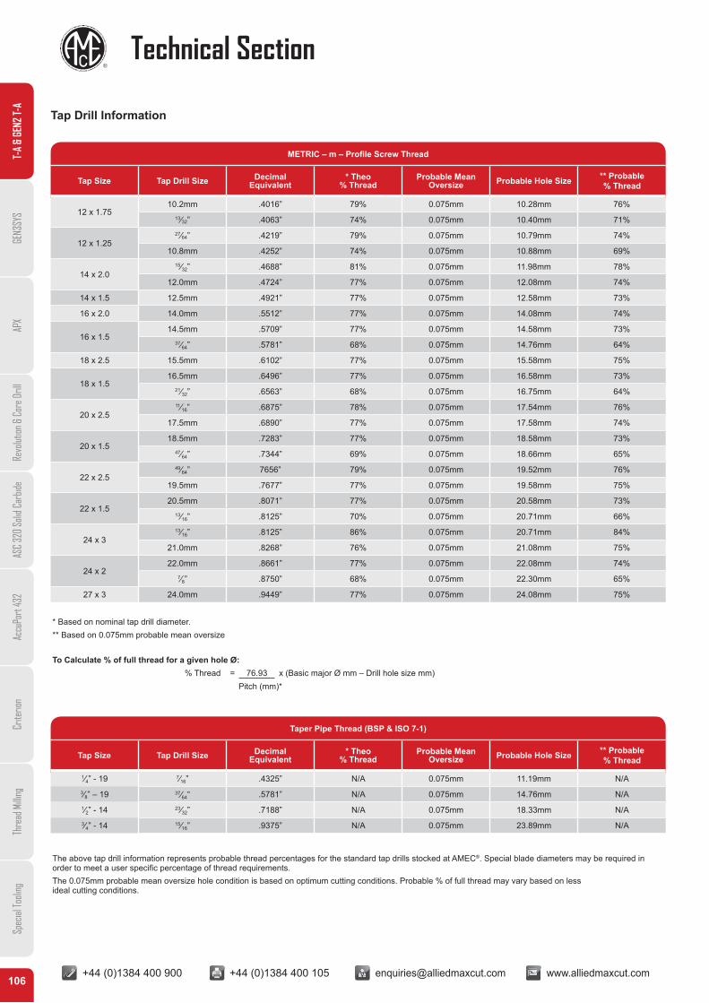
+44 (0)1384 400 900 +44 (0)1384 400 105 [email protected] www.alliedmaxcut.com +44 (0)1384 400 900 +44 (0)1384 400 105 [email protected] www.alliedmaxcut.com106
Technical Section
Tap Drill Information
T-A
& GE
N2 T-
AGE
N3SY
SAP
XRe
volut
ion &
Cor
e Dril
lAS
C 32
0 So
lid C
arbid
eAc
cuPo
rt 43
2Cr
iterio
nTh
read
Milli
ngSp
ecial
Tooli
ng
METRIC – m – Profile Screw Thread
Tap Size Tap Drill Size Decimal Equivalent
* Theo % Thread
Probable Mean Oversize Probable Hole Size ** Probable
% Thread
12 x 1.7510.2mm .4016” 79% 0.075mm 10.28mm 76%
13⁄32” .4063” 74% 0.075mm 10.40mm 71%
12 x 1.2527⁄64” .4219” 79% 0.075mm 10.79mm 74%
10.8mm .4252” 74% 0.075mm 10.88mm 69%
14 x 2.015⁄32” .4688” 81% 0.075mm 11.98mm 78%
12.0mm .4724” 77% 0.075mm 12.08mm 74%
14 x 1.5 12.5mm .4921” 77% 0.075mm 12.58mm 73%
16 x 2.0 14.0mm .5512” 77% 0.075mm 14.08mm 74%
16 x 1.514.5mm .5709” 77% 0.075mm 14.58mm 73%
37⁄64” .5781” 68% 0.075mm 14.76mm 64%
18 x 2.5 15.5mm .6102” 77% 0.075mm 15.58mm 75%
18 x 1.516.5mm .6496” 77% 0.075mm 16.58mm 73%
21⁄32” .6563” 68% 0.075mm 16.75mm 64%
20 x 2.511⁄16” .6875” 78% 0.075mm 17.54mm 76%
17.5mm .6890” 77% 0.075mm 17.58mm 74%
20 x 1.518.5mm .7283” 77% 0.075mm 18.58mm 73%
47⁄64” .7344” 69% 0.075mm 18.66mm 65%
22 x 2.549⁄64” 7656” 79% 0.075mm 19.52mm 76%
19.5mm .7677” 77% 0.075mm 19.58mm 75%
22 x 1.520.5mm .8071” 77% 0.075mm 20.58mm 73%
13⁄16” .8125” 70% 0.075mm 20.71mm 66%
24 x 313⁄16” .8125” 86% 0.075mm 20.71mm 84%
21.0mm .8268” 76% 0.075mm 21.08mm 75%
24 x 222.0mm .8661” 77% 0.075mm 22.08mm 74%
7⁄8” .8750” 68% 0.075mm 22.30mm 65%
27 x 3 24.0mm .9449” 77% 0.075mm 24.08mm 75%
Taper Pipe Thread (BSP & ISO 7-1)
Tap Size Tap Drill Size Decimal Equivalent
* Theo % Thread
Probable Mean Oversize Probable Hole Size ** Probable
% Thread
1⁄4” - 19 7⁄16” .4325” N/A 0.075mm 11.19mm N/A3⁄8” – 19 37⁄64” .5781” N/A 0.075mm 14.76mm N/A1⁄2” - 14 23⁄32” .7188” N/A 0.075mm 18.33mm N/A3⁄4” - 14 15⁄16” .9375” N/A 0.075mm 23.89mm N/A
* Based on nominal tap drill diameter.** Based on 0.075mm probable mean oversize
To Calculate % of full thread for a given hole Ø: % Thread = 76.93 x (Basic major Ø mm – Drill hole size mm)
Pitch (mm)*
The above tap drill information represents probable thread percentages for the standard tap drills stocked at AMEC®. Special blade diameters may be required in order to meet a user specific percentage of thread requirements.The 0.075mm probable mean oversize hole condition is based on optimum cutting conditions. Probable % of full thread may vary based on lessideal cutting conditions.