SYSTIMAX 360™ 1U, 2U and 4U Ultra High Density (UHD) Fiber ... · SYSTIMAX® Solutions...
10
SYSTIMAX ® Solutions www.commscope.com Instruction Sheet 860513324 Issue 7, January 2014 SYSTIMAX 360 ™ 1U, 2U and 4U Ultra High Density (UHD) Fiber Optic Shelf Instructions General The SYSTIMAX 360™ fiber optic shelves UHD-1U, UHD-2U and UHD-4U are 19-inch (483mm) wide rack mounted, ultra high density (UHD) shelves that accommodates 360 InstaPATCH ® distribution modules (DM) and 360 MPO distribution panels (DP). The 1U shelf includes one sliding tray that accommodates four distribution modules. The 2U shelf includes three sliding trays that accommodate four distribution modules each for a total of twelve distribution modules. The 4U shelf includes six sliding trays that accommodate four distribution modules each for a total of twenty four distribution modules. The 360 InstaPATCH ® distribution modules are equipped with single/duplex multi-port LC adapters on the front and MPO adapters on the rear. This product is intended for indoor use or can be used outdoors in a suitable protective enclosure. Ordering information is listed below: Material ID Part No. Description 760173674 360G2-1U-MOD-UHD 360G2-1U UHD shelf, accepts 4 InstaPATCH modules or MPO distribution panels 760173682 360G2-2U-MOD-UHD 360G2-2U UHD shelf, accepts 12 InstaPATCH modules or MPO distribution panels 760173690 360G2-4U-MOD-UHD 360G2-4U UHD shelf, accepts 24 InstaPATCH modules or MPO distribution panels SYSTIMAX 360 ™ UHD-1U, UHD-2U and UHD-4U Fiber Optic Shelves How to Contact Us • To find out more about CommScope ® products, visit us on the web at http://www.commscope.com/ • For technical assistance: - Within the United States, contact your local account representative or technical support at 1-800-344-0223. Outside the United States, contact your local account representative or Authorized Business Partner. - Within the United States, report any missing/damaged parts or any other issues to CommScope Customer Claims at 1-866-539-2795. Outside the United States, contact your local account representative or Authorized Business Partner. © 2014 CommScope, Inc. All rights reserved Page 1 of 10
Transcript of SYSTIMAX 360™ 1U, 2U and 4U Ultra High Density (UHD) Fiber ... · SYSTIMAX® Solutions...
SYSTIMAX® Solutions www.commscope.com
Instruction Sheet 860513324 Issue 7, January 2014
SYSTIMAX 360™ 1U, 2U and 4U Ultra High Density (UHD) Fiber Optic Shelf Instructions
General
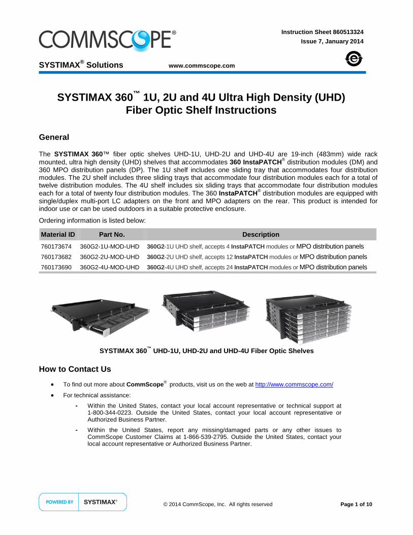
The SYSTIMAX 360™ fiber optic shelves UHD-1U, UHD-2U and UHD-4U are 19-inch (483mm) wide rack mounted, ultra high density (UHD) shelves that accommodates 360 InstaPATCH® distribution modules (DM) and 360 MPO distribution panels (DP). The 1U shelf includes one sliding tray that accommodates four distribution modules. The 2U shelf includes three sliding trays that accommodate four distribution modules each for a total of twelve distribution modules. The 4U shelf includes six sliding trays that accommodate four distribution modules each for a total of twenty four distribution modules. The 360 InstaPATCH® distribution modules are equipped with single/duplex multi-port LC adapters on the front and MPO adapters on the rear. This product is intended for indoor use or can be used outdoors in a suitable protective enclosure.
Ordering information is listed below:
Material ID Part No. Description
760173674 360G2-1U-MOD-UHD 360G2-1U UHD shelf, accepts 4 InstaPATCH modules or MPO distribution panels
760173682 360G2-2U-MOD-UHD 360G2-2U UHD shelf, accepts 12 InstaPATCH modules or MPO distribution panels
760173690 360G2-4U-MOD-UHD 360G2-4U UHD shelf, accepts 24 InstaPATCH modules or MPO distribution panels
SYSTIMAX 360™ UHD-1U, UHD-2U and UHD-4U Fiber Optic Shelves
How to Contact Us
• To find out more about CommScope® products, visit us on the web at http://www.commscope.com/
• For technical assistance:
- Within the United States, contact your local account representative or technical support at 1-800-344-0223. Outside the United States, contact your local account representative or Authorized Business Partner.
- Within the United States, report any missing/damaged parts or any other issues to CommScope Customer Claims at 1-866-539-2795. Outside the United States, contact your local account representative or Authorized Business Partner.
© 2014 CommScope, Inc. All rights reserved
Page 1 of 10

860513324 Instruction Sheet
www.commscope.com
Tools Required
Phillips head screwdriver Isopropyl alcohol Lint-free wipes or tissues.
Separately Orderable Parts Verify parts against the parts list below:
Material ID Part Number Description 760161463 UHD-CBL-BRKT-3/8-NPT Shelf mounted bracket for 3/8” cables
760161471 UHD-CBL-BRKT-1/2-NPT Shelf mounted bracket for 1/2” cables
760058685 RMB-6-3/8 BRACKET Rack mounted bracket (RMB) for 3/8” cables
760058677 RMB-6-1/2 BRACKET Rack mounted bracket for 1/2” cables
760058701 RMB-5-3/4 BRACKET Rack mounted bracket for 3/4” cables
Various Various (see note) 360 InstaPATCH distribution modules (DM)
Various Various (see note) 360 MPO DP distribution panels (DP) 760159822 N/A 12-pair designation label
Note: Contact your local account representative for ordering numbers for modules or panels.
CAUTIONS • Isopropyl alcohol is flammable, and can cause eye irritation on contact. If eye contact occurs, flush with water for at
least 15 minutes. In case of ingestion, consult a physician. Use only in well ventilated areas.
• Disconnected optical components may emit invisible optical radiation that can damage your eyes. Never look directly into an optical component that may have a laser coupled to it. Serious and permanent retinal damage is possible. If accidental exposure to laser radiation is suspected, consult a physician for an eye examination.
• Wearing safety glasses during installation of this shelf is recommended. Although standard safety glasses provide no protection from potential optical radiation, they offer protection from accidental airborne hardware and cleaning solvents.
Step 1 – Verify Parts
Loose Parts Furnished with Shelf Quantity Description
1 Rear door 2 Hardware covers 4 12-24 x 3/8 screws 4 M6 x 12 screws 1 Hook-and-loop kit 2 Port designation labels 2 Adapter designation labels
1. Verify parts shipped with this unit against the parts listed in the table and shown in figure above (4U shelf shown).
Note: Remove tray support brackets on both sides of shelf prior to installation for 2U and 4U shelves.
Sliding traysupport brackets(2 places)Hardware cover
Rear door
Port labels
Shelf
Page 2 of 10

www.commscope.com 860513324 Issue 7, January 2014
Step 2 – Configure Mounting Brackets and Mount Shelf to Equipment Rack
Note: The illustrations in this instruction sheet show the 4U shelf.
Configuration for: 19” (483mm) Rack 23” (584mm) Rack ETSI Rack
1. Remove tray support brackets, as shown in Step 1, on both sides of shelf prior to installing 2U and 4U shelves.
2. Configure mounting brackets on shelf to match type of equipment rack shelf is being installed on. Note: Shelf brackets are factory configured for 19-inch (483mm) rack mounting.
3. Align tabs on mounting brackets (two per bracket) with holes on front of equipment rails. 4. Install shelf to front of equipment rails and secure with supplied hardware; four 12-24 x 3/8” screws for 19-
inch (483mm) rack and 23-inch (584mm) racks and four M6 x 12 screws for ETSI racks. 5. Snap hardware covers over front of mounting brackets.
Page 3 of 10
860513324 Instruction Sheet
www.commscope.com
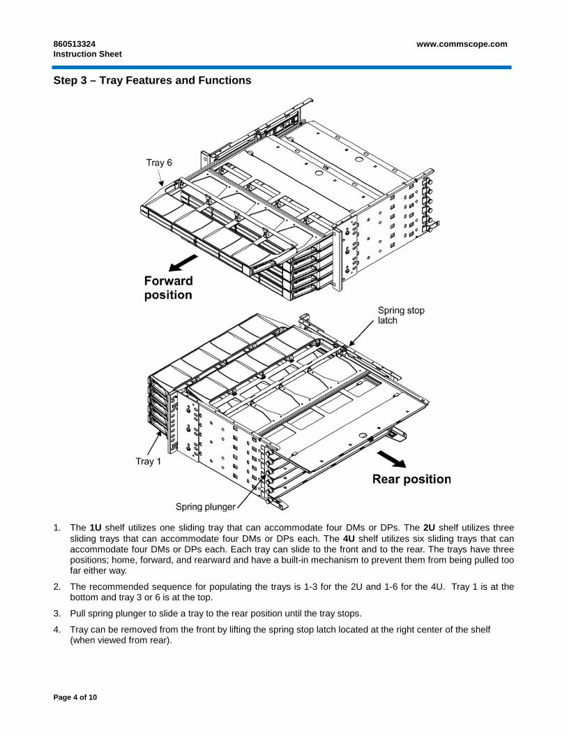
Step 3 – Tray Features and Functions
1. The 1U shelf utilizes one sliding tray that can accommodate four DMs or DPs. The 2U shelf utilizes three
sliding trays that can accommodate four DMs or DPs each. The 4U shelf utilizes six sliding trays that can accommodate four DMs or DPs each. Each tray can slide to the front and to the rear. The trays have three positions; home, forward, and rearward and have a built-in mechanism to prevent them from being pulled too far either way.
2. The recommended sequence for populating the trays is 1-3 for the 2U and 1-6 for the 4U. Tray 1 is at the bottom and tray 3 or 6 is at the top.
3. Pull spring plunger to slide a tray to the rear position until the tray stops.
4. Tray can be removed from the front by lifting the spring stop latch located at the right center of the shelf (when viewed from rear).
Page 4 of 10

www.commscope.com 860513324 Issue 7, January 2014
Step 4 – Configure and Install 360 InstaPATCH® Plus Modules
Front Front
Rear Rear
ALPHA label
BETA label
Distribution Module in ALPHA Configuration Distribution Module in BETA Configuration
Note: DMs must be configured as shown for proper polarity. Identical InstaPATCH modules are used at both ends of trunk cable, but module orientation is inverted from end to end. DM at one end of trunk cable must be oriented in “ALPHA” configuration, while module at opposite end of trunk cable must be oriented in “BETA” configuration.
1. Orient DMs in the “ALPHA” or “BETA” configuration as shown above before installation.
Module shownbeing installed in tray 3,position B
Tray 3 pulled forward
Position A ofpositions A – D
Patch cover
Tray 1
Note: InstaPATCH modules are not included and must be ordered separately.
2. Slide tray forward and lift patch cover to the open position.
3. Starting at the left-most position in tray 1, slide module into position labeled “A” in bulkhead.
Note: Illustration shows DM being installed into tray 3, position B.
Page 5 of 10

860513324 Instruction Sheet
www.commscope.com
Step 5 – Terminate Trunk Cables
Shelf mountedbracket
Rackmountedbracket
144Ftruck cable
Tray pulledto rear
Shelf mounted bracketTighten cable gland nut96F trunk cable
Cable gland
Tighten cablegland nut
High Density Trunks 1. Secure incoming cables to 4U shelf using either the separately orderable shelf mounted brackets or the rack
mounted brackets (RMB). For rack mounted brackets, follow instructions included with the brackets.
2. Mount trunk cables to rack mounted brackets or shelf mounted brackets as shown above.
3. Pull sliding tray to the rear to terminate trunk cable fanouts.
Page 6 of 10

www.commscope.com 860513324 Issue 7, January 2014
Low Density Trunks
1. When using 24F trunks, one trunk per module, secure 4 trunk cables (2 each side) aligned to each tray. Alternate adjacent cables between front column of shelf mount brackets and rear column of shelf mount brackets as shown.
2. Rotate shelf mounted brackets as shown to provide more room to route trunks.
3. Pull sliding tray to rear to terminate 24F trunk cable fanouts.
Page 7 of 10
860513324 Instruction Sheet
www.commscope.com
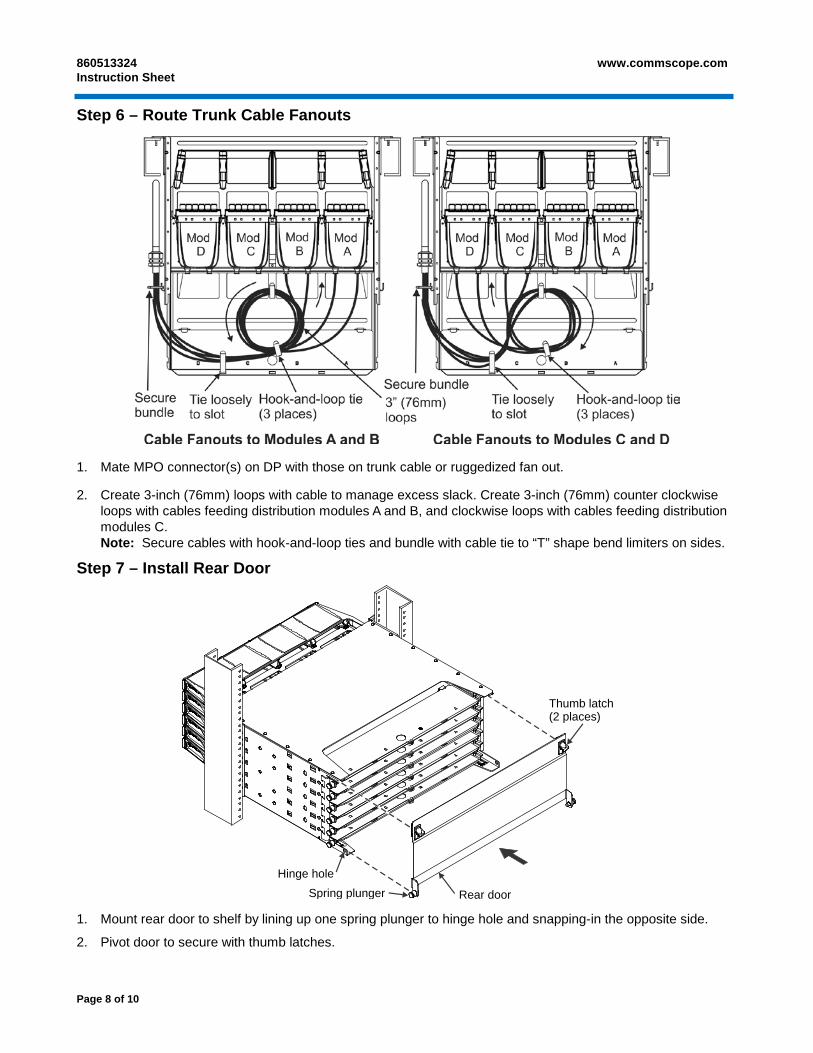
Step 6 – Route Trunk Cable Fanouts
1. Mate MPO connector(s) on DP with those on trunk cable or ruggedized fan out.
2. Create 3-inch (76mm) loops with cable to manage excess slack. Create 3-inch (76mm) counter clockwise loops with cables feeding distribution modules A and B, and clockwise loops with cables feeding distribution modules C. Note: Secure cables with hook-and-loop ties and bundle with cable tie to “T” shape bend limiters on sides.
Step 7 – Install Rear Door
1. Mount rear door to shelf by lining up one spring plunger to hinge hole and snapping-in the opposite side.
2. Pivot door to secure with thumb latches.
Rear door
Thumb latch(2 places)
Spring plungerHinge hole
Page 8 of 10
www.commscope.com 860513324 Issue 7, January 2014
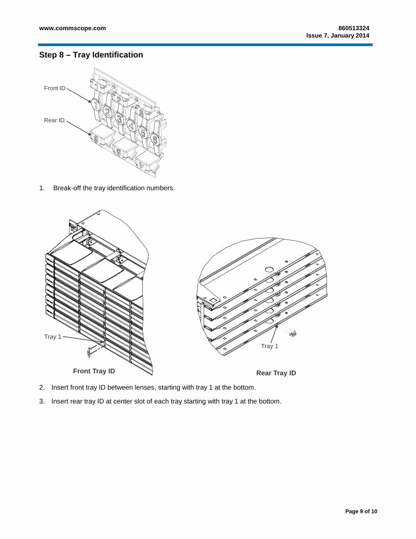
Step 8 – Tray Identification
1. Break-off the tray identification numbers.
2. Insert front tray ID between lenses, starting with tray 1 at the bottom.
3. Insert rear tray ID at center slot of each tray starting with tray 1 at the bottom.
Front Tray ID Rear Tray ID
Tray 1Tray 1
Rear ID
Front ID
Page 9 of 10
860513324 Instruction Sheet
www.commscope.com
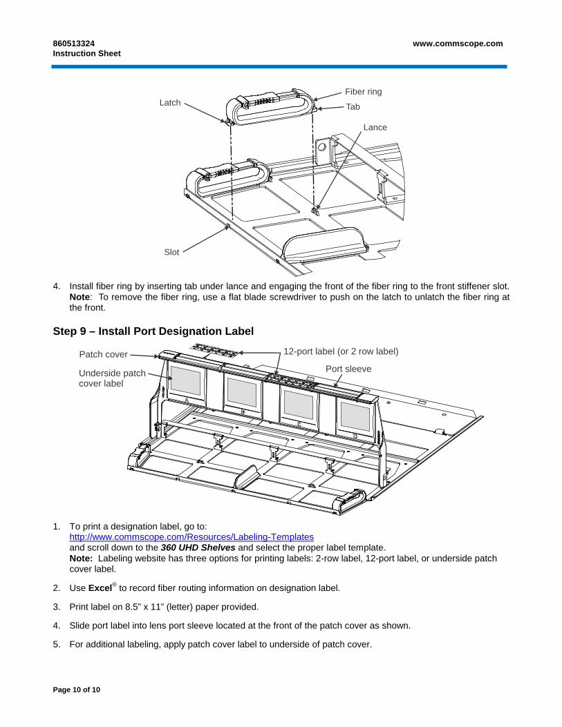
4. Install fiber ring by inserting tab under lance and engaging the front of the fiber ring to the front stiffener slot. Note: To remove the fiber ring, use a flat blade screwdriver to push on the latch to unlatch the fiber ring at the front.
Step 9 – Install Port Designation Label
Underside patchcover label
Patch cover 12-port label (or 2 row label)
Port sleeve
1. To print a designation label, go to:
http://www.commscope.com/Resources/Labeling-Templates and scroll down to the 360 UHD Shelves and select the proper label template. Note: Labeling website has three options for printing labels: 2-row label, 12-port label, or underside patch cover label.
2. Use Excel® to record fiber routing information on designation label.
3. Print label on 8.5” x 11” (letter) paper provided.
4. Slide port label into lens port sleeve located at the front of the patch cover as shown.
5. For additional labeling, apply patch cover label to underside of patch cover.
Lance
Slot
LatchFiber ring
Tab
Page 10 of 10