sYSTEMS UTILIZATION BRANCH RADIO DIVISION II …
22
A4 dTZ N R L MEMORANDUM REPORT No. 83 A NEW METHOD OF CALIBRAT ING FIELD STRENGTH MEASURING EQUIPMENT Harold E. Dinger Wi lliam E. Garner RADIO DIVISION II 14 November 1952 @~r NAVAL RESEARCH LABORATORY, WISHIIITOI, D.C. l'l , E. JS I~ /Uffl US T l/I S C O/'} 'f'O: NAVAL RESEARCH LABORATORY WASHINGTON, D.C. 2037 5 ATTN: CODE 26 28 BN·au~ of ,mr limih.·d ~uppl y you :ire n."4.tUt>idNI lo r, •lurn f hi i,.; <'OJ 1Y nK i,.01H ) n ~ it h:, s H•n't•rf your pur pohf' K HO that it Hl,ly he 1u:u.lc.• :-wailu l1l £' jo ulht.>1 -S for ..... rl'tl'lll'l. \I~(. Your ,-.:)('l llf'r..thon will I~\ appn-;.•iated. N0W- NRL-5070/2035 ( Rev, 3- 73) e1srR1eur10N STA 1 eMe~ir A AP?UES l=\Hthet dletr1butlon authorized by ____ _ --- IJ /UIY! fft f} _ ___ r,r. y. j
Transcript of sYSTEMS UTILIZATION BRANCH RADIO DIVISION II …

A4 dTZ
N R L MEMORANDUM REPORT No. 83
A NEW METHOD OF CALIBRATING FIELD STRENGTH MEASURING EQUIPMENT
Harold E. Dinger William E . Garner
RADIO DIVISION II
14 November 1952
@~r NAVAL RESEARCH LABORATORY, WISHIIITOI, D.C.
l'l,E. JS I~ /Uffl US T l/IS CO/' } 'f'O:
NAVAL RESEARCH LABORATORY W ASHINGTON, D.C. 20375
ATTN: CODE 26 28 BN·au~ of ,mr limih.·d ~upply you :ire n."4.tUt>idNI lo r,•lurn f hii,.; <'OJ1Y nK i,.01H) n ~ i t h:,s H•n't•rf your pur pohf'K HO tha t it Hl,ly he 1u:u.lc.• :-wailu l1l£' jo ulht.>1-S for ..... rl'tl'lll'l. \I~(. Your ,-.:)('lllf'r..thon will I~\ appn-;.•iated.
N0W- NRL- 5070/ 2035 (Rev , 3 -73)
e1srR1eur10N STA1eMe~ir A AP?UES l=\Hthet dletr1butlon authorized by ____ _
---IJ/UIY!fftf} _ ___ r,r. y.
j

•
TEXT
FOR
NRL MEMORANDUM REPORT NO. 83
A NEW METHOD OF CALIBRATING
FIELD STRENGTH MEASURING EQUIPMENT
14 NOVEMBER 1952
sYSTEMS UTILIZATION BRANCH
RADIO DIVISION II
NAVAL RESEARCH LABORATORY
WASHINGTON 25, D. C.

ABSTRACT
AUTHORIZATION
INTRO DU CTI ON
THEORY
Dh'TAILll!J P!iOCJIDUllE
SIHPLlFlli1J PROCEDURE
TABLE I
CONTENTS
ii
iv
iv
l
l
3
7
lC
,,
.,

ABSTRACT
A new method of calibrating radio interference and field strength measuring equi pment employing shielded loop antennas has been developeda It is based on the concept of the shielded loop antenna acting as a unity coupled transformer; the shield being the primary and the inner conductor the secondary. It is assumed that the loop dimensions are small compared to the wavelength, that the shield is made of a highly conductive nonferrous material, and that the inner turns do not approach resonance when open circuited. The calibrating signal is inject ed into the l oop shield across the shield gap. This signal voltage is equal to the voltage that would be induced in the shield of the loop by an electromaenetic f i eld of the intensity at which it is desired to calibrate t he equipment. The principal advantages of this method are : simplicity, wide range of calibration levels, and adaptability to field use.
PRDBLEH STATUS
This is a... interim report on one phase of these problems; work is continuing on t his and other phases of the pr oblems.
AUTH OJUZATION
Problems No. 391l)7-41 and No. 39R07-26
iv

'
Subj: A New ;,:ethod of Calibrating :field Strength Weasuring Equipment
Ref: (.)
(b)
Terman, F. E., 11 Radio Engineer's Handbook11, McGraw-Hill Book
Company, 1943, pp 813-815. Libby, L. L., "Special Aspects of Balanced Shielded Loops", Proceedings of I.R,E., Vol. 34, p 643, September, 1946.
INTRODUCTION
1. J.~ost of the modern radio interference and field strength measuring equipments operating below 25 megacycles employ shielded loop antennas either as the primary pickup device or as an accessory. These equipments frequently require recalibration and it is common practice in many instances for the user to return the equipment to the manufacturer or a standardizing agency for this purpose, or sh,ply to continue to use the equipment and assume H to be calibrated correctly. The calili ration methods now in general use require rather precise and critical installations, or are subject to error, and the more accurate methods are practically impossible to use out in the field.
2. While making a study of the calibration methods now in general use, a new method was developed which has a very high degree of accuracy and is very simpl8 to apply, even in the field. Some phases of the investigation of this method are still being carried on; however, the application of this method for the calibration of the Stoddart Aircraft Radio Company Radio Interference-Field Intensity Meters NM-10.A (Navy Model AN/Uru.1-6) and ;,,1.!:-20A (Navy Model .AN/PR.M-1) has been completed. This report will therefore include the procedure for applying this method to these instruments along with a discussion of the general theory of the method.
TH>XlRY
3. The shield-injection method of calibrating radio interference and field strength measuring equipment is applicable only to equipments employing shielded loop antennas, the dimensions of which are small compared to the wavelength. It is assumed that the loop shield is made of a highly conductive, nonferrous material such as copper, aluminum, or brass, and that the inner conductor does not approach resonance when open-circuited. It is based on the concept of the shielded loop antenna actinb as a closely coupled transformer; the shield being the primary and the inner conductor the secondary. When such an antenna is placed in an electromagnetic field, the magnetic component of the field induces a voltage in the shield and the total induced voltage appears across the shield gap. The coefficient of coupling between the shield and the inner conductor is unity, and therefore, the open-circuit output voltage of the loop is equal to the product of the shield gap voltage and the number of turns of the inner conductor, provided·that the inner conductor does not approach resonance when open-circuited.
l
,. ,. ~ ,. ., .. •·

4. If the shield of a loop without any inner conductor were placed in an electr omagnetic field in free space, a voltage (Es) would be induced in the shi eld and the total voltage could be cal culated from the equation, r eference (a) ,
(1)
where Es = the voltage induced in the shield in microvolts, £ = the field strength of the field in microvolts per meter , N = the number of turns (shield) , A = the mean area of the loop in square meters, A = the wavelength in meter s , g = the directi on of travel of wave with respect to pl ane of loop.
For the ordinary loop shield N equals one. If there were an open- circuited conductor inside t his shield, and it did not approach r esonance in this condition, then there would be negligible reacti on between the shield and the inner conductor, and the induced voltage would be the same as that without an inner conductor present.
5. In most methods of calibrating radio interference and field strength measuring equipment employing shielded l oop antennas, a radio- frequency field, the strength of which is calculated, i s produced, and the antenna is placed in this field. The shield- injection method is a direct signal insertion type of calibration. The voltage that a lmown field would induce into the shield (Es) is injected across the shi eld gap.
6. Up until now, all the discussion has been concerni.ng the open-circuited loop. When a load, such as the input circuit of a radio interference or field strength meter and the connecting cable, if any, is connected to the output of the shielded loop antenna, in an electromagnetic field, the shield gap voltage and the l oop output voltage change by some amount depending upon the impedance of the load. These voltages may further change as the meter i s tuned. Since it is r ather difficult to calculate t hese changes in the loop voltages, the shield- injection method is based on open- circuit voltage calculations. If the shield gap voltage induced by a particular field, with the l oop output open- circuited, is replaced by a vol tage of the same frequency and magnitude from a constant- current (high- Dnpedance) source connected acr oss the shield gap, and some impedance is then connected across the loop out put, the shield gap voltage and the loop output voltage will change by the saJ11e amount as they would if the loop were in an electromagnetic field. In the application of the shield injection method, a current is caused to flow in the l oop shield. Although the shield gap voltage and the l oop output voltages change depending upon the load impedance, the shield current must r emain constant. Therefore, a constant- current (high- impedance) signal source must be used. The calibration of a radio interference or field str ength meter by the shield- injection method is done by first calculating the shield gap vol tage (Es) from equation (1) for a field strength level at
2
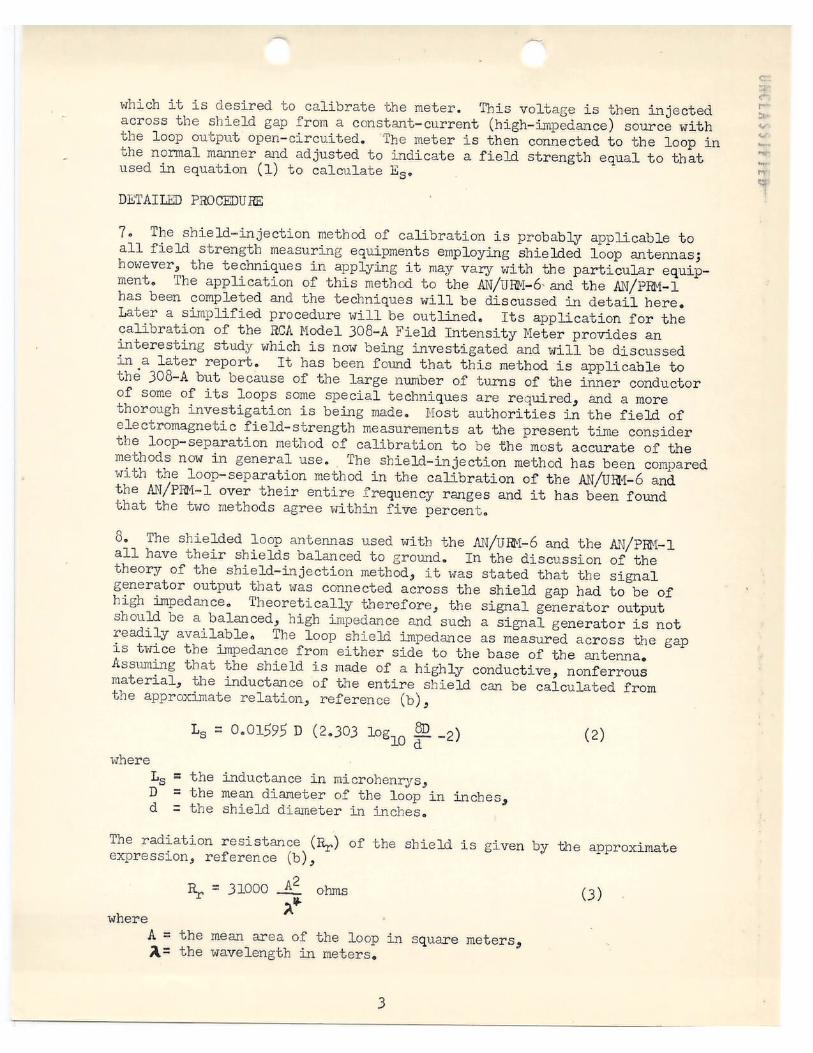
which it is desired to calibrate the meter. This voltage is then injected across the shield gap from a constant- current (high-impedance) source wi th tbe loop output open- circuited. The meter is then connected to the loop in the nonnal manner and adjusted to indicate a field strength equal to that used in equation (1) to calculate Es•
DETAILED PROCEDURE
?. The shield-injection method of cal ibration is probably applicabl e to all field strength measuring equipments employing shielded loop antennas; however, the techniques in applying it may vary with the part icular equipment. The application of this method to the AN/URM- 6- and the AN/PRM- 1 has been completed and the techniques will be discussed in detail here. Later a simplified procedure will be outlined. Its applicati on for t he calibration of the RCA Model 308-A Field Intensity Meter provides an interesting study which is now being investigated and will be discussed in a later report. It has been fo,md that this method is applicabl e t o the 308-A but because of the large number of turns of the inner conductor of some of its loops some special techniques are required, and a more thorough investigation is being made. Nost authorities in the field of electromagnetic field-strength measurements at the present time consider the loop-separation method of calibration to be the most accurate of the methods now in general use. 'fhe shield- injection method has been compared with the loop- separation method in the calibration of the AN/URM- 6 and the AN/PIM-1 over their entire frequency ranges and it has been found that the two methods agree within five percent.
8. The shielded loop antennas used with the AN/UR-1-6 and the AN/PR-1- 1 all have their shields balanced to ground. In the discussion of the theory of the shield- injection method, it was stated that the signal generator output that was connected across the shield gap had to be of high impedance. Theoretically therefore, the signal generator output should be a balanced, high impedance and such a signal generator is not readily available. The loop shield impedance as measured across the gap is twice the impedance from either side to the base of the antenna. Assuming that the shield is made of a highly conductive, nonferrous material, the inductance of the entire shield can be calculated from the approximate relation, reference (b),
Ls= 0.01595 D (2. 303 log10 ~ - 2)
where Ls = the inductance in microhenrys, D = the mean diameter of the loop in inches, d = the shield diameter in inches.
(2)
The radiation resistance (R.r,) of the shield is given by the approximate expression, reference (b) ,
~ = 31000 A2 ohms (3) ")...
where A= the mean area of the loop in square meters, A= the wavelength in meters.
3

Using equation (3) the radiation resist ance of t he AN/PBM-1 loop and most loops would be of the grder of 0.002 ohms or less and of the two AN/UR-1- 6 loops is less than 10- ohms. The inductive reactance of the shields of most loops is also very low but it is very high compared with the radiation resistance. With the loop output open-circuited, the inductive reactance of the shields of the loops used with the AN/UliM- 6 and the AN/PR-1- 1 was measured at 200 kilocycles to be
AN/UIM-6 thirty- inch loop,
AN/UR-116 five-inch loop,
AN/PRM-1 loop,
x1 = 2.11 ohms
x1 = 0.176 ohms
x1 = O. 522 ohms
Therefore, since the radiation resistance is small enough to be neglected, the impedance of either side of the shield gap above ground would be just half this value, assuming ground t o be at the base of the antenna, and the impedance varies directly with frequency. The action of the loop as an antenna depends upon the impedance of either side of the shield gap to the base and not necessarily to the true electrical ground. In most instances the base of the shielded loop antenna is not at zer o potential with respect to other parts of the ground system. In order for connections made to either side of the shield gap to have negligible effect on the loop action, the impedance of the added circuitry between the gap and the base of the loop must be very high compared with tbe shield impedance between the gap and the base. It has been found, that if certain precautions are taken, an unbalanced signal generator connected as shown in Figure l can be used for the calibration of most r adio interference and field strength measuring equipments.
9. When calibrating the AN/U~1-6 and the AN/PRM-1 by the shield-injection method the follouing precautions should be taken in order to use an unbalanced signal generator connected as shown in Figure l. The series resistor (R) serves to keep the impedance connected across the gap high compared with the shield impedance, and to keep the load impedance essentially constant and hi gh compared with the internal impedance of the signal generator. The equipment being calibrated should not be grounded or connected to the signal generator in any \Jay other tban by the signal generator output cable. There may be a ground connection through the power line but the impedance of this ground lead would be high enough so as not to have any effect on the calibration. The coaxial cable connecting the signal gener ator output to the shield gap should be at least three feet long.
10. The first step i n the calibration procedure is to calculate the gap voltage that would be induced into the shield by a field of some particular intensity. The gap voltage is calculated from equation (1). The mean effective areas of the loops under discussion are given in Table I . For the particular loop in question, equation (1) can be reduced to the folloui..,g form using the frequency (f) in megacycles, and cos g equals one.
4

AN/Uru.~-6 thirty-inch loop: E, • 9710 X 10-6/r (4)
AN/um:-6 five-inch loop: (5)
AN/PRM-1 loop, (6)
The loop of the equipment to be calibrated should be mounted in the same relative position as used in making measurements but with the loop output open-circuited~ That is, if the loop is normally mounted on the meter for measurement pur,Poses, it should be so mounted for calibration. In the oase of the AN/URM-6, the five inch loop should be mounted on the meter in its normal way but the cable used to connect the loop to the meter should be disconnected at the loop output connector. The thirty-inch loop should be mounted on its tripod with its accompanying cable disconnected at the loop output~ For the AN/PRM-1, a special adaptor must be lll,9.de to permit mounting of the loop in its normal posit°ion but disconnected at its output. If the adaptor increases the height of the loop above the meter case by an inch or so, the effect is negligible. The shielded output cable of a standard signal generator is then cOnneoted across the gap in the loop shield as shown in F'igure L The series resistor (R) should be of the order of a thousand ohms or more to raise the impedance connected across the gap and to prevent loading of the signal generator. More will be said in the simplified procedure concerning the exact value of this resistance. The connections to the shield should be made immediately at the edges of the gap and the open lead lengths from the end of the signal generator output cable to the shield should be as short as possible including the length of the series resistor (R). It is necessary to keep these open leads short because their lenGth may increase the effective area of the loop. There should not be any other large metallic objects near the loop. The signal generator should be about three feet or more from the loop. Figure 2 shows the calibration installa,tion for the .AJ.1/PRM-l. The figure shows the loop rather close to the signal generator; however, this was only for the purpose of grouping for the picture.
11. Because of the series resistor (R), the applied gap voltage is not equal to the outpu·t; voltage of the signal generator 0 Therefore, the applied gap voltage must be measured. This can be done very satisfactorily by using the meter being calibrated as a transfer deviceQ Since there is no input to the meter when the gap voltage is first applied, the Antenna Input of the meter can be used to measure this gap voltage. To do this, a signal of the desired frequency and equal to the calculated gap voltage (E 8 ) should first be fed into the Antenna Input of the meter through the proper impedance matching network (CU-186/URM-6 or CU-195/PRM-l as the case may be). This is done by connecting the signal generator output cable to a four or five foot length of fifty-ohm coaxial cable
5

which is connected to the meter through the impedance matching networ k. The meter is then tuned and adjusted to indicate some convenient value . The si gnal generator output is again connected to the shiel d gap t hr ough the series resistor. The four to five foot length of coaxial cabl e i s then connected directly across the shield gap with 11gr ound11 t o the same side as the signal generator "ground" lead. The other end of the cable is left connected t o the meter as before without di st urbing the settings of any of the meter controls. The signal generator output i s then adjusted so that the meter indicates the same value as before. The voltage into the met er cable, which is the voltage applied across t he gap, is the desired gap voltage. The signal generator output voi tage (Eg) should be noted. The cable connected between the shield gap and the meter Antenna Input should be disconnected. Tbe loop output i s t hen connected to the meter input in the nonnal manner. The meter should then be tuned and adjusted to indicate a fie ld strength equal to that used in the calculation of t he gap voltage (Es) • Any l oop factors that ar e normall y used in field strength measurements with the particul a r loop and meter should also be used in determining the field strength indication for the shield- injection calibration. For exampl e ; if the AN/ U~i- 6
. is being calibrated using t he thirty- inch loop t he factor of 10 must be appli ed to the field strength indice.tion. If the meter was being calibr ated at a field strength of 1000 microvolts per meter, the meter should read 100 microvolt s if the Xl step of the Attenuator is used or 10 microvol t s if the XlO step is usecI:" Gap voltage measurement s made in the manner outlined above should in general be made at some fre uenc below about 00 kilocycles. There may be considerable error in thi s method of measure
ment f or t he AN/P™-1 loop at frequencies above 800 kil ocycles because of gap loading. This, however, does not limit the calibration of the equipment to frequencies below 500 kilocycles.
NarE : The gap voltage is rather low for some loops at the lower frequencies even for rather large field strengths. It may be found convenient to use the gap voltage calculated for a field strength of one volt per meter . After the signal Benerator output voltage (Eg), required to produce this gap voltage, has been determined, the signal gener ator output voltage can be reduced proportionally to produce the gap vol tage and field strength indication desired. The gap volt age and f ield strengt h indication is directly proportional to the signal generator output voltage.
12. It is necessary to measure t he gap voltage at only one frequency, and for any particular lcop this measurement has to be made only once, since information obtained from this one measurement can be used f or future calibrat i on of the equipment without repeat ing t he gap vpl t age measurement. In the application of the shield- injection method, a current (Is) is caused to flow in the shield of the loop. This ~urr ent is constant whether the loop is open- circuited or l oaded. The field strength indication of the equipment being calibrated is dlrectly proportional to this current. I f the magnitude of this current (Is) to. produce a certain field. strength indication could be calculated then it would not be necessary to measure t he gap voltageo Thus far, an equation
6
.,.. ..

for the accurate calculation of this current has not been derived. However, the shield current can be determined experimentall y for any particular loop and equipment. As mentioned before, the impedance of the shield is very low. I f the series r esistance (R) shmm in Figure 1 is very l arge compared with the shield impedance, then the shield current (Is) for practical purposes can be calculated from the expression
= ~ R (7)
where Eg i s the signal gener ator output voltage required to give the necessary gap voltage and R is the resistance of the series resistor. It has already been shown that the resistive component of the shield impedance, when the l oop is open- circuited, is negligible. Hence, the open-circuited shield impedance can be considered to vary directl y Hi.th frequency. The shield gap vol tage is equal to the product of the shield impedance and shi eld current. Assuming a constant field strength, the open- circuit gap voltage varies directly wit h frequency, and the shield current (15 ) is constant with frequency. Therefore, once the shield curr ent necessary to produce a certain f ield strength indication has been determined, the gap voltage need not be calculated or measured again for the particul ar loop and equipment. The shield current necessary to produce a certain field strength has been determined exper imentally for the AN/URM-6 and the AN/PRH- 1. This greatly simplifies the procedure for the calibr ation of these equipments.
NOTE : Throughout this report the term 11 signal generator output voltage°TEg) " is the voltage that appears at the output end of the signal generator output cable. In some signal cenerators, such as the Model LP-S shown in Figure 2, the voltage output of the signal generator as read on the output calibration dials is not necessarily t he voltage that appears at the output end of the cable. This, of course, is especiall y true at the higher frequencies where the error can be very l arge . In such a case the voltage at the output end of the cable can be calculated from the signal generator output setting, the frequency, and the impedance and length of the output cable. The use of a signal generator which employs a properly terminated output cable eliminates this difficulty.
SIMPLIFIED PROCEDURE
]J . In the application of the shield-injection method, the shield gap voltage and the loop output voltaee may change depending upon whether the loop output is open-circuited or loaded and with changes in t he load impedance. However, the current (I5 ) flowing in the shield must remain constant during these changes in voltage. If the series r esistance (R) is very large compared to the impedance of the shield under these various conditions, the signal generator will see a practically constant load impedance and therefore its output current, uhich i s the same as the shield current, will remain constant. This principle of constant current, and the fact that the field strength i.~dication i s proportional to this current, makes the shield-injection method very simple to apply once the value of this current per unit of field strength has been determined.
7

-14. If the shield current per unit of field strength is kno~m, it is not necessary to first inject the calibrat ing si gnal with t he loop output opencircuited. The equipment to be calibrated should be set up in the same manner as for making field strength measurements with the loop antenna. The desir ed loop should be mounted and connected t o the meter input in its normal manner. There should not be any metallic masses near the loop other than what is required for the calibration. The signal gener ator output should be connected to the shield gap as shown in Figure 1 and previous]¥ discussed, and the loop should be about three feet from the generator. The signal generator is then set to the desired frequency and its out put voltage (Eg) is adjusted so that
= ( 8)
This output voltage (E) is the voltage appearing at the output end of the signal generator outpuf cable as noted previously. The meter being calibrated is then adjusted to indicate a field strength proportional to the value of current used. The shield currents (Is) required for the three loops under discussion are listed in Table I . These currents are listed for the particular loop as so many microamperes per vol t per meter. For example, if the AN/UR-1-6 was being calibrated using the thirty- inch loop, and a shield current of 920 microamper es wer e used, the meter should indicate a field strength of one volt per meter. If 0.92 microarnperes were used then the field strength indication would be 1000 microvol ts per meter si nce the field strength is dir ectly pr oportional t o t he shield cur rent. The same antenna factors must always be applied to the field strength indications for the shield-injection calibr ation as when making field strength measurements.
15. It will be found very convenient to make the value of the series resistor (R) such that the field strength indicati on in microvolts per meter is equal to the signal generator output (Eg) in microvolts. The correct value of series resistance to do this for the loops and meters discussed is given in Table I . If these values of resistance given in the table are used for R in Figure 1, and it is desired to calibrate the meter at 1000 microvolts per meter, simply set the signal generator to the desired f requency and the output voltage (Eg) to 1000 micr ovolts and adjust the equipment being calibrated to indicate a field strength of 1000 microvolts per meter. It may be found that the value of the series resistances listed in Table I is not high enough to avoid loading of some signal generators. A load resistance of 1000 ohms decreases the output of the LP-5 by about 4.5 percent when the Xl0,000 step of the attenuator is used. However, if the lower attenuator steps of the attenuator are used, a load resistance of 1000 ohms causes negligible loading of the output. This loading effect must be taken into account in the determination of the true signal generator output voltage (Eg) or a higher series resistor should be used. If a resistance of ten times the value quoted were used, it would probably be high enough to avoid loading in most signal generators and the field strength indication in microvolts per meter would be one-tenth the signal generator output voltage in microvolts.
8
<,.(> <,, 1 ., •'I

NOTE : The series resistor (R) should have a good frequency chara~stic so that its r esistance does not change over the range of frequencies used for calibr ation.
16. Figures 2 through 6 show the three loops used with the AN/UHM-6 and the AN/PRN-1 and t heir respective coupling devices used to calibrate the · equipment by the shield-injection method. The original coupling devices that were made for the investigation of this calibration method had two mounted coaxial connectors. One was f or the connection of the signal generator output and the ot her was for the connection of t he cable to measure the gap voltage. If the shield current technique is used the second connector is unnecessary. The coupling devices shown in the photographs have been found to be very convenient. The ones used for the AN/UIM- 6 loops are mounted permanently and do not affect the normal operation of the loops provided nothing is connected to the coupling device when radio interfer ence or f ield strength measurements are made. The coupling device used f or the AN/PR-1-1 loop snaps into place for calibr ation or can be left mounted permanently.
17. Most signal gener ators have an upper limit of output voltage at about one vol t . Since, in most instances in calibrating with the shield injection method, the field strength indication in microvolts per meter is equal to the signal generator output voltage in microvol ts, the equipment can be calibrated at pr actically 3~y level desired including very high levels of field strength. In most )ther methods of calibration this is not easily accomplished, and calibration must be done at t he lower l evels of field strength. It is advantageous to be able to calibrate at the higher field strength levels especially if it is necessary to calibrate the equipment in the presence of high ambient radio interference. Under such conditions it may be possible to calibrate the equipment at a level much higher than the ambient interference and thereby not intr oduce an error in the calibration. Also, for accurate field strength measurements it is general)¥ possible to make the measurements by the direct substitution method and eliminate any error in the scale tracking, attenuator, or internal calibration of the meter. To make measurements by the direct substitution method, the meter is tuned to the signal to be measured and the antenna is or iented fo r maximum pi ckup. The gain of the meter is adjusted for some convenient indication. The loop is then oriented to a null or the signal may be turned off, if possible, and the controls on the meter are not disturbed. The shield-injection method of calibration i s then applied in the nonnal manner except that the meter controls are not disturbed and the signal generator is tuned to the meter frequency and its output voltage is adjusted so that the meter again indicates the same as it did when receiving the radiated signal. The field strength can then be calculated in the nonnal way for the shield-injection method.
~~-0~ Harold. E. Dinger
~~~~ William E. Garner
9

Loop
TABLE I
SHIELD-INJECTION CALIBRATION DATA FOR AN/UR1- 6 AND AN/P:m,1-1
A(l) Sq. Meters
AN/UR-t- 6 :
Thirty-inch loop
Five- inch loop
AN/PR11- l l oop
0. 464
0.0141+
0.0323
920
340
260
1090
2940
3850
(1) (2)
(3)
The mean effective area (A) of the loops in square meters. The shield- injection shield current (I5 ) expressed in microamperes per volt per meter. (See Text) The series resistance (R) necessary to make the f ield strength indication in microvolts per meter equal the signal generator output voltage in microvolts.
10

r·
ILLUST RATIONS
FOR
NRL MEMORANDUM REPORT NO. 83

LOOP SHIELD GAP
~
R
I I I I I I
, -1--., I I
TO SIGNAL GENERATOR
Figure 1 - Schematic Drawing Showing Connections for Calibrating the AN/ URM-6 and the AN/PRM-1 by the Shield Injection Method.
)
Jl:t f 1 i .(.~ ;", :'\~ •'i

Figure 2 Shield Injection Calibration Installation for the AN/PRM-1

BERYLLIUM-COPPER CONTACTS
RESISTOR
Figure 3 The AN/PRM-1 Loop With Shield Injection Coupling Device

Figure 4 The AN/ URM-6, 30 Inch Loop, With Shield Injection Coupling Device Connected ~ :l 1 -1 r -: c :; 11 ~: n

Figure 5 The AN/URM-6, 30 Inch Loop, Shield Injection Coupling Device Opened to Show Connections f!'.11, ,,_~ .. ,,.,,'.fl
j

Figure 6 The AN/URM-6, 5 Inch Loop With Shield Injection Coupling ,, 'a r ., "" -; ·.' "\ · Device Connected