Systems of Commercial Turbofan...
24
Systems of Commercial Turbofan Engines
Transcript of Systems of Commercial Turbofan...
Systems of Commercial Turbofan Engines
Andreas Linke-Diesinger
Systems of CommercialTurbofan Engines
An Introduction to Systems Functions
123
Andreas Linke-DiesingerLufthansa Technik AGPropulsion Systems EngineeringWeg beim Jäger 19322335 [email protected]
ISBN 978-3-540-73618-9
DOI 10.1007/978-3-540-73619-6
e-ISBN 978-3-540-73619-6
Library of Congress Control Number: 2007940818
© 2008 Springer-Verlag Berlin Heidelberg
This work is subject to copyright. All rights are reserved, whether the whole or part of the material isconcerned, specifically the rights of translation, reprinting, reuse of illustrations, recitation, broadcasting,reproduction on microfilm or in any other way, and storage in data banks. Duplication of this publicationor parts thereof is permitted only under the provisions of the German Copyright Law of September 9,1965, in its current version, and permission for use must always be obtained from Springer. Violationsare liable for prosecution under the German Copyright Law.
The use of general descriptive names, registered names, trademarks, etc. in this publication does not imply,even in the absence of a specific statement, that such names are exempt from the relevant protective lawsand regulations and therefore free for general use.
Typesetting and production: LE-TEX Jelonek, Schmidt & Vöckler GbR, Leipzig, GermanyCover design: Frido Steinen-Broo, eStudio Calamar, Spain
Printed on acid-free paper
9 8 7 6 5 4 3 2 1
springer.com
Preface
Many textbooks describing the function of a turbine engine are available on the market. These books describe the operation of the main components of an engine, its thermodynamic principles and the principle of thrust gen-eration. They are available at any required level. For persons that first get in touch with the subject matter of turbine engines it is also important to understand the operation of the systems necessary for the operation of a turbine engine.
With my long-term experience as a technical training instructor the idea developed to write a description of the engine systems to provide this as an add-on to the many text books available describing the operation of the ba-sic turbine engine. For a complete understanding of functions of the engine systems it is important not to describe the systems isolated from the air-craft. Systems of modern turbine engines are highly integrated into the air-craft system architecture. Thus the functional interface with the aircraft is shown were necessary.
It took some time to find a concept for this book that provides the in-formation in a sequence that facilitates the understanding of the described functions. During the writing of this book I got some help from experts in their field for the optimization of the result. I wish to thank Johannes Lange and Dr. Hans Hansen for their expertise concerning the concept of this book; Sybille Schmidt and Wolfgang Lehmann for their useful linguis-tic suggestions.
I also mustn’t forget to thank my family for their patience while I worked on this book for some months.
Hamburg, August 2007
Table of Contents
1 Introduction ................................................................................................ 1
1.1 Engine Systems in General ................................................................. 1
1.1.1 Grouping of Engine Systems ....................................................... 2
1.1.2 Demands on Engine Systems ...................................................... 5
1.2 Digital Aircraft Systems...................................................................... 8
1.2.1 General .......................................................................................... 8
1.2.2 Federated Avionics Architecture............................................... 11
1.2.3 Integrated Modular Avionics..................................................... 11
1.3 Aircraft-Engine Interface .................................................................. 13
1.3.1 Structural Interface ..................................................................... 13
1.3.2 System Interfaces ....................................................................... 14
1.4 Thermal Management........................................................................ 14
1.4.1 Thermal Management for Engine Parts .................................... 14
1.4.2 Thermal Management for Fuel and Oil .................................... 14
1.5 Sample Engines.................................................................................. 15
1.6 Definitions and Terms ....................................................................... 16
1.6.1 Gas Path Stations........................................................................ 16
1.6.2 Pressure Ratios ........................................................................... 18
1.6.3 Shaft Speed Designations .......................................................... 19
1.6.4 Corrected Parameters ................................................................. 19
1.6.5 Location Designations on Cases................................................ 20
2 Engine Air Systems .................................................................................. 23
2.1 Internal Air Systems .......................................................................... 23
2.1.1 Component Cooling and Sealing............................................... 23
2.1.2 Pressure Balancing ..................................................................... 27
2.1.3 Bearing Compartment Pressurization ....................................... 28
2.2 External Air Systems ......................................................................... 29
2.2.1 Cooling and Ventilation Systems .............................................. 29
2.2.2 Active Clearance Control Systems............................................ 31
2.2.3 Compressor Control Systems .................................................... 38
3 Engine Lubrication System .................................................................... 49
3.1 General ............................................................................................... 49
3.1.1 Properties of Engine Oil ............................................................ 49
3.1.2 System Design and Components............................................... 51
3.2 Lubricated Areas................................................................................ 53
3.3 System Components .......................................................................... 55
3.3.1 Oil Tanks..................................................................................... 55
3.3.2 Pumps and Filters ....................................................................... 56
3.3.3 Oil Cooling ................................................................................. 58
3.3.4 Vent System Components.......................................................... 59
3.4 System Indications and Monitoring.................................................. 60
3.4.1 Indication of Operating Data ..................................................... 60
3.4.2 Indication System Sensors ......................................................... 62
3.4.3 Data Processing, System Monitoring........................................ 62
3.4.4 Debris Monitoring ...................................................................... 63
4 Engine Fuel Distribution System........................................................... 67
4.1 General ............................................................................................... 67
4.1.1 Properties of Fuel ....................................................................... 67
4.1.2 Fuel Supply of the Engine ......................................................... 69
4.2 Engine-Mounted Fuel Distribution System ..................................... 70
4.2.1 System Design and Components............................................... 70
4.2.2 Operation .................................................................................... 72
4.3 Thermal Management for Fuel and Oil............................................ 77
4.3.1 Oil Coolers and Fuel Temperature ............................................ 77
4.3.2 The Oil Cooling System of the CFM56-7B.............................. 78
4.3.3 The Oil Cooling System of the CFM56-5A, -5B and -5C....... 78
4.3.4 The Oil Cooling System of the PW4000 .................................. 80
4.3.5 The Oil Cooling System of the V2500-A5 ............................... 81
5 Engine and Fuel Control System ........................................................... 85
5.1 Main Tasks of the System ................................................................. 85
5.2 Speed and Thrust Control.................................................................. 85
5.2.1 Shaft Speed Control ................................................................... 86
5.2.2 Thrust Control ............................................................................ 87
5.2.3 Engine Thrust Ratings................................................................ 90
5.3 Hydromechanical Control Systems .................................................. 93
5.3.1 Engine Control System of the CFM56-3 .................................. 93
5.3.2 Control System of the CF6-80C2 (PMC Version) ................... 96
5.4 FADEC System.................................................................................. 98
5.4.1 System Design ............................................................................ 99
5.4.2 The EEC.................................................................................... 101
5.4.3 The Sensors............................................................................... 109
5.4.4 Aircraft / Engine Interface ....................................................... 110
VIII Table of Contents
IX
5.4.5 FADEC Systems of Selected Engines .................................... 112
5.4.6 Future Trends in FADEC System Designs............................. 120
6 The Aircrew/Engine Interface.............................................................. 121
6.1 Engine Indications ........................................................................... 121
6.1.1 Indicated Engine Parameters ................................................... 121
6.1.2 Engine Indications on an Electronic Instrument System ....... 125
6.1.3 Engine Indications on a Classical Instrument System ........... 132
6.2 Engine Controls ............................................................................... 136
6.2.1 HP Fuel Shut-Off Control System .......................................... 137
6.2.2 Mechanical Thrust Lever Systems .......................................... 140
6.2.3 Electrical Thrust Lever Systems.............................................. 142
6.2.4 Control Switches ...................................................................... 145
6.2.5 Thrust Control during Automatic Flight ................................. 146
7 Starting and Ignition.............................................................................. 151
7.1 The Starting System......................................................................... 151
7.1.1 General ...................................................................................... 151
7.1.2 Starting System Components................................................... 152
7.2 The Ignition System......................................................................... 156
7.2.1 General ...................................................................................... 156
7.2.2 Ignition System Components................................................... 157
7.3 Cockpit Controls and Indications ................................................... 161
7.3.1 Starting System and Ignition System of the CFM56-3 .......... 161
7.3.2 Start System and Ignition System of the CFM56-7B............. 163
7.3.3 Start System and Ignition System of the V2500-A5.............. 165
8 Thrust Reverser Systems ...................................................................... 167
8.1 Operation of Thrust Reversers ........................................................ 167
8.1.1 Basic Principle.......................................................................... 167
8.1.2 Reverser Operation................................................................... 168
8.2 Types of Thrust Reversers .............................................................. 168
8.2.1 Airflow Deflection Systems .................................................... 169
8.2.2 Actuation Systems.................................................................... 171
8.2.3 Reverser Control Systems........................................................ 172
8.3 Reverser Structure ........................................................................... 173
8.3.1 Fixed Structure ......................................................................... 173
8.3.2 Movable Structure and Actuation System Components ........ 174
8.4 Reverser Control System................................................................. 175
8.4.1 Control System of the B737-600............................................. 175
8.4.2 Control System of the A320 .................................................... 177
X Table of Contents
9 Engine Anti-Ice System ......................................................................... 179
9.1 Ice Build-Up on Engine Parts ......................................................... 179
9.2 Air Inlet Anti-Ice System ................................................................ 179
9.2.1 General ...................................................................................... 179
9.2.2 System Components of a Pneumatic Anti-Ice System .......... 180
9.3 Spinner Anti-Ice............................................................................... 181
10 Power Plant ........................................................................................... 185
10.1 Nacelle............................................................................................ 185
10.2 Bare Engine.................................................................................... 186
10.3 Power Plant Build-Up ................................................................... 186
10.3.1 Engine Mounts ....................................................................... 188
10.3.2 Inlet Anti Ice System ............................................................. 190
10.3.3 Electrical Power Generation.................................................. 190
10.3.4 Pneumatic System .................................................................. 191
10.3.5 Hydraulic System ................................................................... 193
10.3.6 Fuel Supply System ............................................................... 194
10.3.7 Fire Detection and Extinguishing System ............................ 194
10.3.8 Mechanical Engine Controls ................................................. 197
10.3.9 Sensors and Harnesses ........................................................... 198
10.3.10 Engine Fluid Drains ............................................................. 198
Appendix A Data Transfer in Digital Aircraft Systems...................... 199
A.1 Serial Interfaces .............................................................................. 199
A.2 Data Buses....................................................................................... 201
A.2.1 ARINC 429 .............................................................................. 201
A.2.2 ARINC 629 .............................................................................. 202
A.2.3 AFDX....................................................................................... 203
Appendix B Servo Valve Control for Actuator Positioning ............... 207
B.1 General............................................................................................. 207
B.2 Servo Valves with Spill Valves ..................................................... 207
B.3 Servo Valves with Fuel Jet Nozzle ................................................ 209
B.4 Servo Valves with Pilot Valves ..................................................... 210
B.5 Fail-Safe Actuator Positioning....................................................... 211
Appendix C Unsuccessful Engine Starts................................................ 213
C.1 Types of unsuccessful Engine Starts ............................................. 213
C.1.2 The Hot Start............................................................................ 213
C.1.3 The Wet Start ........................................................................... 215
C.1.4 The Hung Start......................................................................... 216
C.1.5 The Start Stall .......................................................................... 217
XI
C.2 Further Abnormal Start Conditions detectable by FADEC Systems .................................................................................... 218
Glossary ...................................................................................................... 219
Bibliography............................................................................................... 227
Index ............................................................................................................ 229
Abbreviations
AC Alternating Current ACC Active Clearance Control ACOC Air-Cooled Oil Cooler ADC Air Data Computer AFDX Avionics Full Duplex Switched Ethernet AIMS Aircraft Information Management System ALF Aft Looking Forward ARINC Aeronautical Radio Inc. ASC Aircraft System Computer ASTM American Society for Testing and Materials ATA Air Transport Association of America A/THR Autothrust AVM Airborne Vibration Monitoring
CBP Customer Bleed Pressure CCS Common Core System CDP Compressor Discharge Pressure CIT Compressor Inlet Temperature CONT Continuous COTS Commercial Off The Shelf CS Certification Standard
DAC Dual Annular Combustor DC Direct Current DEU Display Electronic Unit DMC Display Management Computer
EASA European Aviation Safety Agency ECAM Electronic Centralized Aircraft Monitor ECM Engine Condition Monitoring ECU Electronic Control Unit EEC Electronic Engine Control EFIS Elecronic Flight Instrument System EHSV Electrohydraulic Servo Valve EIA Electronic Industries Alliance
XIV Abbreviations
EICAS Electronic Indication and Crew Alerting System EIU Engine Interface Unit EIVMU Engine Interface and Vibration Monitoring Unit EPR Engine Pressure Ratio EUROCAE European Organisation for Civil Aviation Equipment E/WD Engine/Warning Display
FADEC Full Authority Digital Engine Control FCU Fuel Control Unit FDRV Fuel Diverter and Return Valve FF Fuel Flow FIFO First In First Out FLA Forward Looking Aft FMC Flight Management Computer FMU Fuel Metering Unit FMV Fuel Metering Valves FOB Fuel On Board FRT Flat Rate Temperature ft Feet FWC Flight Warning Computer FWD Forward
GRD Ground
HMU Hydromechanical Unit HPC High Pressure Compressor HPT High Pressure Turbine
IDG Integrated Drive Generator IEEE Institute of Electrical and Electronics Engineers IGN Ignition IMA Integrated Modular Avionics IPC Intermediate Pressure Compressor IPT Intermediate Pressure Turbine ISA International Standard Atmosphere
LLP Life Limited Part LPC Low Pressure Compressor LPT Low Pressure Turbine LRM Line Replaceable Modules LRU Line Replaceable Unit LVDT Linear Variable Differential Transformer
MCDU Multipurpose Control and Display Unit MEC Main Engine Control
Abbreviations XV
MEMS Microelectromechanical Systems Mn Mach Number
N1, N2, N3 Engine Rotor Speeds
OAT Outside Air Temperature ODM Oil Debris Monitor
PMC Power Management Control PPBU Power Plant Build-Up
QEC Qick Engine Change
REV Reverse RTD Resistive Thermal Device RTDCA Radio Technical Commission for Aeronautics RTOS Real Time Operating Systems RVDT Rotary Variable Differential Transformer
SAL System Address Label SDAC System Data Aquisition Computer SOAP Spectrographic Oil Analysis Program
TAPS Twin Annular Premixing Swirler TAT Total Air Temperature TBV Transient Bleed Valve TIA Telecommunication Industry Association TLA Thrust Lever Angle TOGA Take-Off/Go Around TRA Thrust Lever Resolver Angle TSFC Thrust Specific Fuel Consumption
UART Universal Asynchronous Receiver-Transmitter
VBV Variable Bleed Valve VSV Variable Stator Vane
Company Names
Airbus Airbus S.A.S., Blagnac Cedex, France Boeing Boeing Commercial Airplanes, Renton, Wash., USA CFM CFM International S.A., Melun, France GEAE or GE GE Aviation, Cincinnati, Ohio, USA IAE International Aero Engines, East Hartford, Ct., USA LTT Lufthansa Technical Training, Hamburg, Germany Pratt & Whitney Pratt & Whitney, East Hartford, Ct., USA RR Rolls-Royce International Ltd., London, UK
1 Introduction
1.1 Engine Systems in General
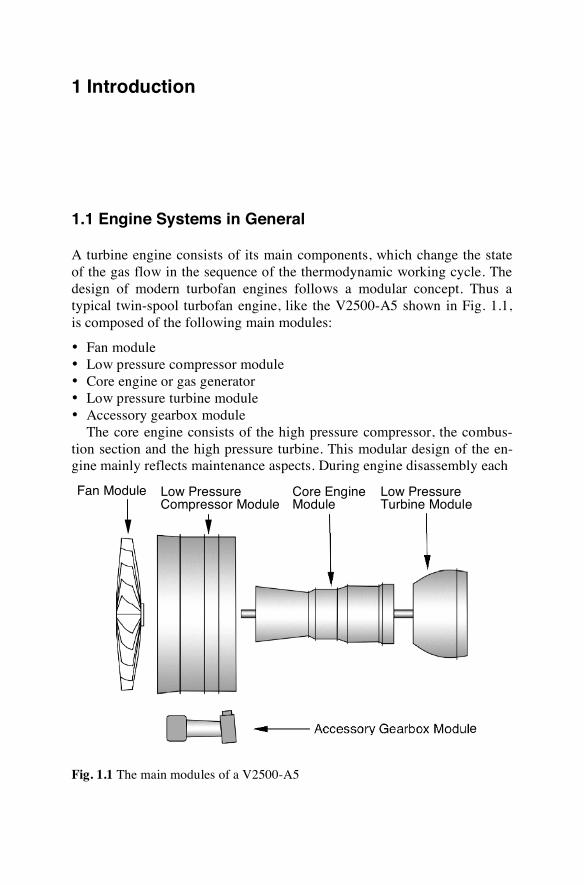
A turbine engine consists of its main components, which change the state of the gas flow in the sequence of the thermodynamic working cycle. The design of modern turbofan engines follows a modular concept. Thus a typical twin-spool turbofan engine, like the V2500-A5 shown in Fig. 1.1, is composed of the following main modules:
• Fan module • Low pressure compressor module • Core engine or gas generator • Low pressure turbine module • Accessory gearbox module
The core engine consists of the high pressure compressor, the combus-tion section and the high pressure turbine. This modular design of the en-gine mainly reflects maintenance aspects. During engine disassembly each
Fig. 1.1 The main modules of a V2500-A5
Fan Module Low Pressure Compressor Module
Core Engine Module
Low Pressure Turbine Module
Accessory Gearbox Module
2 1 Introduction
module can be removed from the engine without disassembling it into its piece parts. For the assembly process of the engine the modules are pre-assembled and then assembled to the complete engine. Each module has its specific maintenance schedules and as well as skill and tool requirements.
Besides reflecting maintenance aspects this modular concept is likewise useful to describe elementary functions of engine operation and incidences of the working cycle. In the following this compound of modules will be referred to as the basic engine.
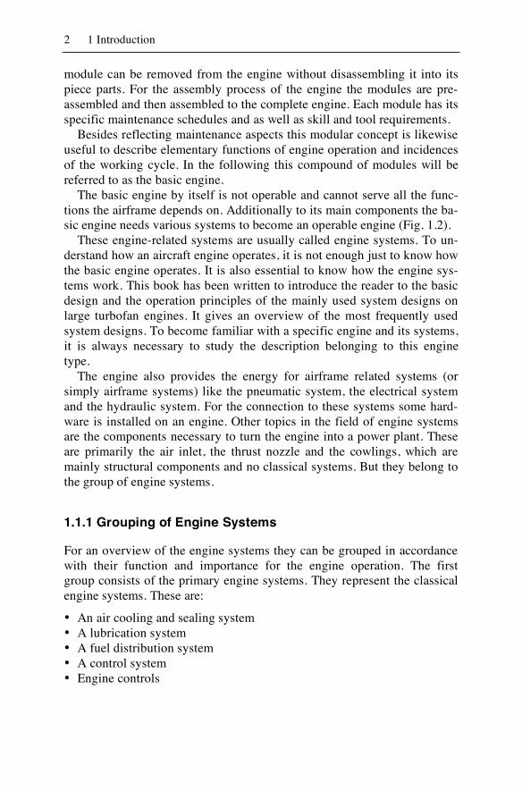
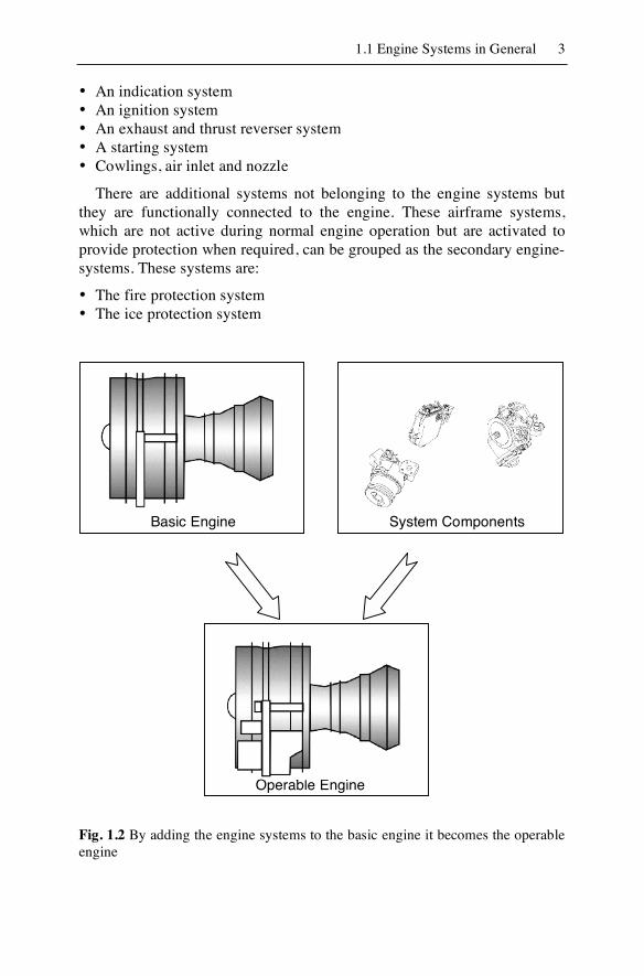
The basic engine by itself is not operable and cannot serve all the func-tions the airframe depends on. Additionally to its main components the ba-sic engine needs various systems to become an operable engine (Fig. 1.2).
These engine-related systems are usually called engine systems. To un-derstand how an aircraft engine operates, it is not enough just to know how the basic engine operates. It is also essential to know how the engine sys-tems work. This book has been written to introduce the reader to the basic design and the operation principles of the mainly used system designs on large turbofan engines. It gives an overview of the most frequently used system designs. To become familiar with a specific engine and its systems, it is always necessary to study the description belonging to this engine type.
The engine also provides the energy for airframe related systems (or simply airframe systems) like the pneumatic system, the electrical system and the hydraulic system. For the connection to these systems some hard-ware is installed on an engine. Other topics in the field of engine systems are the components necessary to turn the engine into a power plant. These are primarily the air inlet, the thrust nozzle and the cowlings, which are mainly structural components and no classical systems. But they belong to the group of engine systems.
1.1.1 Grouping of Engine Systems
For an overview of the engine systems they can be grouped in accordance with their function and importance for the engine operation. The first group consists of the primary engine systems. They represent the classical engine systems. These are:
• An air cooling and sealing system • A lubrication system • A fuel distribution system • A control system • Engine controls
1.1 Engine Systems in General 3
• An indication system • An ignition system • An exhaust and thrust reverser system • A starting system • Cowlings, air inlet and nozzle
There are additional systems not belonging to the engine systems but they are functionally connected to the engine. These airframe systems, which are not active during normal engine operation but are activated to provide protection when required, can be grouped as the secondary engine-systems. These systems are:
• The fire protection system • The ice protection system
Fig. 1.2 By adding the engine systems to the basic engine it becomes the operable engine
System Components Basic Engine
Operable Engine
4 1 Introduction
The systems associated with the energy supply to the aircraft are grouped as the supply systems. They derive power, respectively air supply, from the engine but are also integral parts of their respective airframe sys-tem. These systems are:
• Electrical power generation system • Pneumatic system • Hydraulic power system
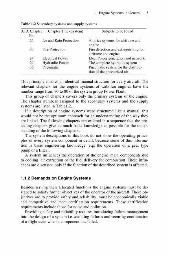
The reader may have the first contact with a technical description of an aircraft or engine type in the form of a training manual or a maintenance manual. In civil aviation it is international standard to group and name the systems in these publications according to ATA Specification 100 “Manu-facturers´ Technical Data”. This specification gives the chapter numbering standard for technical manuals used in civil aviation. In this standard each system of an aircraft has its own chapter with a standardized title and chap-ter number. The following Table 1.1 shows this in detail.
Table 1.1 ATA Chapter Numbers and Titles
ATA Chapter No.
Chapter Title (System) Subjects to be found
70 Standard Practices - Engines Standard Procedures to be observed while working on the engine
71 Power Plant Air inlet, cowlings, engine mounts, power plant removal / installation
72 Engine Description and inspections of the engine from the compressor to the turbine and the gearbox.
73 Engine Fuel and Control Fuel distribution system, engine con-trol system and fuel indication.
74 Ignition Engine ignition System 75 Air Engine air systems for cooling and
compressor control. 76 Engine Controls Engine controls and its components. 77 Engine Indication Engine indications for power (EPR
or Torque), RPM (N1, N2, N3), tem-perature (EGT, Nacelle Temp.) and vibration.
78 Engine Exhaust Nozzle structures and thrust reverser system.
79 Engine Oil Engine lubrication system and the related system indications.
80 Starting Engine starting system.
1.1 Engine Systems in General 5
Table 1.2 Secondary systems and supply systems
ATA Chapter No.
Chapter Title (System) Subjects to be found
26 Ice and Rain Protection Anti-ice systems for airframe and engine
30 Fire Protection Fire detection and extinguishing for airframe and engine
24 Electrical Power Elec. Power generation and network 29 Hydraulic Power The complete hydraulic system 36 Pneumatic Pneumatic system for the distribu-
tion of the pressurized air
This principle ensures an identical manual structure for every aircraft. The relevant chapters for the engine systems of turbofan engines have the number range from 70 to 80 of the system group Power Plant.
This group of chapters covers only the primary systems of the engine. The chapter numbers assigned to the secondary systems and the supply systems are listed in Table1.2.
If a description of engine systems were structured like a manual, this would not be the optimum approach for an understanding of the way they are linked. The following chapters are ordered in a sequence that the pre-ceding chapters give as much basic knowledge as possible for the under-standing of the following chapters.
The system descriptions in this book do not show the operating princi-ples of every system component in detail, because some of this informa-tion is basic engineering knowledge (e.g. the operation of a gear type pump or a filter).
A system influences the operation of the engine main components due to cooling, air extraction or the fuel delivery for combustion. These influ-ences are discussed only if the function of the described system is affected.
1.1.2 Demands on Engine Systems
Besides serving their allocated functions the engine systems must be de-signed to satisfy further objectives of the operator of the aircraft. These ob-jectives are to provide safety and reliability, must be economically viable and competitive and meet certification requirements. These certification requirements include those for noise and pollution.
Providing safety and reliability requires introducing failure management into the design of a system i.e. avoiding failures and securing continuation of a flight even when a component has failed.
6 1 Introduction
Avoiding operating errors can be accomplished by reducing the pilot’s workload, through automation of systems, by providing limit protection and informing the pilot about system malfunctions and proposing appro-priate responses. Failures of system components and of the total system can also be avoided by designing robust and fail-proof components.
If the reliability assessment of a component reveals weaknesses, other modes of operation must be provided in the event of a component failure. This is usually done by providing redundancy. Redundancy may also serve to increase dispatch reliability.
Efficient means of improving economy of operation are the reduction of weight, size and acquisition cost and optimizing operation with respect to fuel consumption and operational life.
A significant contribution to a safe and economic operation can be de-rived by proper maintenance. The design of a modern engine is, to a con-siderable extent, determined by its maintenance concept. E.g. the modular design of system components and easy accessibility will allow to replace components that have a higher failure probability in the limited time frames available when the aircraft is in line service.
A valuable contribution to an effective maintenance program is the con-tinuous recording of data of the status and operation of all systems. The evaluation of this information allows to perform:
• System diagnosis • Trend monitoring • Failure and maintenance action prediction
As a consequence the systems of modern engines are provided with a multitude of sensors. The data sensed are not only used for the control of the engine or the system but also for the monitoring and analysis of the system condition. The data are fed into a central processing and data stor-age module. Some analysis is done by the on-board equipment, and further calculations are performed by ground-based computers.
Control of the systems is predominantly performed by embedded soft-ware which operates in real time and which interacts with the hardware functions. The software interprets input data from the sensors or data buses directly, processes the information and drives electrically commanded out-put devices.
This control system depends on a reliable data transfer and a reliable electrical power supply system. Software is also used to provide system monitoring, health diagnostic and fault monitoring information, which is processed for indication to the flight crew and stored for maintenance pur-poses.
1.1 Engine Systems in General 7
Thus all systems of a modern engine are highly integrated and perform complex and interrelated functions within a federated system of data gen-eration and transfer. Control and data processor functions are not per-formed in each system itself but in a central processor.
Thus when investigating a specific system it is important to notice that the specific functions of the system have not been the only design objec-tives. Safety, reliability, efficiency and maintenance functions are also im-portant. A system meets these objectives best as a member of a combina-tion of federated systems, which are generally controlled by embedded software and which exchange data with other system computers.
There are several textbooks providing the reader with the knowledge of the mechanical as well as aerodynamic and thermodynamic aspects of tur-bine engine designs. It is not the intention of this book to repeat what is al-ready documented elsewhere. It is even expected that the reader has a gen-eral knowledge of the design and operation of a turbine engine that he can find in these textbooks. The design principles provided there will be rele-vant for many future generations of turbine engines. But as has been demonstrated, there has been an evolutionary change in the design of the last generation of modern turbine engines driven by reliability, economic and maintenance considerations. This evolution has been made possible by introducing additional new technologies that have become available by in-troducing data processing into engine design. These evolutionary changes become especially apparent when comparing the engine systems of older and the newest turbine engine designs.
In most relevant text books the systems of the jet engines are not cov-ered in much detail. The influence of the new technologies discloses itself mainly in the design of the systems and systems architecture, which are not adequately represented either. The new technology systems have become a dominant factor in the operation and economic viability of the modern tur-bine engine.
Thus, as stated at the beginning, it is the intention of this book to give an introduction to the systems of modern civil turbofan engines. These dem-onstrate a significant change compared to respective older designs. The in-troduction to the systems will be given by investigating the systems of some of the current generation of turbofan engines powering the present generation of large commercial transport aircraft. As these systems proved to be very successful, their design principles have also been adopted in the newest generation of smaller turbofan engines used in regional and busi-ness aircraft.
This investigation concentrates on the primary systems that support the operation, control and supply of the basic engine. The supply systems
8 1 Introduction
(pneumatic, electrical power generation and hydraulic power) will only be covered in so far as they interact with the engine.
Generally speaking, an insight into the design and operation of the sys-tems and the interoperability with other systems is given. No methods to design a system or to analyze the operation of a specific system are pre-sented.
1.2 Digital Aircraft Systems
1.2.1 General
The reader may ask why an introduction to digital aircraft systems makes sense in a book about engine systems. It makes sense because transport aircraft have undergone significant changes during the last decades with the adoption of the digital technology available during their design phases. Digital technology has been applied to individual systems throughout the aircraft, including the engine, allowing them to become more reliable, lighter and easier to maintain. Thus a general description of the digital technology of aircraft systems seems to be justified.
These systems also provide more functionality than their predecessors. Onboard computers now control many of those functions that were con-trolled by pilots and flight engineers on aircraft of older designs. A flight engineer is no longer required and the pilot’s systems related function has changed from a system controller to a supervisor.
The computers controlling the aircraft systems and providing communi-cation between these systems generally share the same technology. Thus the expression avionics, originally used only for systems like communica-tion and navigation, is also used for the digital components of other sys-tems.
A computer embedded in a hardware component and interacting with the system may e.g. operate as a closed loop controller. It continuously samples sensor outputs, calculates appropriate control responses and sends those responses to actuators. In safety critical applications multiple instal-lations of sensors and computers are available and the control loop be-comes more complicated by the addition of a redundancy management and synchronization and voting mechanics. Thus basic elements for a system controller are sensors, a processor, actuators and communication systems for data exchange with remote sensors and other aircraft systems.
1.2 Digital Aircraft Systems 9
1.2.1.1 Sensors
Sensor output quality is a significant factor for control functions, cockpit indications and data collection for monitoring and maintenance support. The introduction of new technologies as e.g. microelectromechanical sys-tems (MEMS) in combination with modern microprocessors has greatly improved sensor output quality.
Sensors that are used in digital control and data acquisition systems must provide an electric signal in digital format. Generally sensing ele-ments, e.g. electro-mechanical systems (MEMS), produce an analog output signal. Depending on the output quality of the output signal it is directly fed into an analog/digital converter or it is amplified and filtered before en-tering the analog/digital converter.
The converter output is fed into a microcomputer in which several algo-rithms are implemented that may serve the following functions:
• Compensation for fabrication imperfections • Compensation for temperature and non-linearities • Digital filtering
Built-in automatic test functions provide both continuity and power checks to examine the integrity of the device.
The microcomputer can be configured to transmit its output as an analog signal or in a standard serial communication protocol such as RS-232, RS-422, RS-485 or ARINC 429. Bidirectional communication allows the user to calibrate the sensor without removal. Signals from a number of such sensors can be multiplexed and transmitted on a single pair of wires.
Not all sensors use all the features presented here but most of these fea-tures are available on pressure transducers used for such safety critical ap-plications as FADEC systems and air data computers. The above-mentioned properties e.g. are found on the “smart” pressure transducer Honeywell LG-1237 of which up to nine are installed in the CFM56-5C engine’s FADEC computer.
The sensor/microprocessor unit will have to communicate and thus in-terface with the embedded system. Interface standards will be described in more detail in Appendix A.
1.2.1.2 Processor
The capabilities a processor must provide are determined by the applica-tions it has to serve. There is a clear tendency to replace, wherever possi-ble, mechanical functions by software functions. E.g. the FADEC com-puter installed on modern engines weighs in the order of 15 kg. It does not
10 1 Introduction
only replace a hydromechanical fuel control of older engines, which weighs in excess of 50 kg on large engines, but also provides many more functions and a higher reliability. Embedded computers may incorporate hardware well known from PCs, but they differ in the operating system they use.
American and European regulators have published documents RTCA/DO-178B respectively EUROCAE ED-12B that define guidelines for the development of safety-critical software for the use in airborne sys-tems. These documents comprise five levels of safety-criticality with level A requiring the most demanding certification process.
Because an airborne system will only be certificated if its software meets the standard, special operating systems have been developed. They simplify the certification process.
Besides supporting safety-critical applications the operating systems must be generally able to support time-critical applications. There are two time-critical applications:
• Time Sharing Under all operating conditions a high priority computation is completed within a predetermined time frame. Closed loop controllers, e.g. the fuel metering controller of an engine, require that sampling sensor output and computing control responses are continuously fully completed within a defined time frame.
• Event Driven If a message has been received or a computation has identified a certain condition, a response is triggered within a predetermined time frame. Such a system may trigger an alert message, may activate envelope pro-tection or the ignition system.
Operating systems providing time-critical services are called real time operating systems (RTOS). They do not actually perform real-time compu-tations but guarantee that predetermined deadlines for the execution of computations are met. These are multi-tasking systems. They incorporate task schedulers, which make sure that high priority tasks are continuously fully completed within the set time frame.
An embedded system serving as an element for a control loop will inter-act with its hardware by transmitting signals to the actuators like fuel me-tering devices, hydraulic actuators, solenoid valves etc. Generally these re-quire analog signals for their operation. Thus digital/analog converters are installed to provide the appropriate command signals. Further details about the diverse types and functions of actuators will be given in connection with the description of the systems to which they belong.
1.2 Digital Aircraft Systems 11
Many of the aircraft systems must communicate with each other. The engine control system, e.g., may require thrust demand signals from the autothrust system. This data transfer is mainly performed with the help of data buses.
1.2.2 Federated Avionics Architecture
Data communication between safety critical systems implies the danger of failure propagation from one system to another. One strategy satisfying certification standards is arranging safety critical applications in a feder-ated architecture. This means that each function (e.g. autothrust) has its own fault tolerant computer with only limited interconnections to systems of other functions. Interactions are limited to the transfer of data. Functions are available which detect or allow to tolerate faulty data or isolate a faulty data source. This is an effective means of preventing fault propagation, be-cause the systems providing different functions do not share any resources. The failure of one function has little effect on the continued operation of others. The partitioning of functional capabilities into separate computers allows to provide appropriate levels of redundancy offering a maximum of safety and dispatch reliability.
A bus system appropriate to federated avionics architecture is the ARINC 429. Transport aircraft using the ARINC 429 data bus in a feder-ated avionics architecture are the Airbus A320, A340 and the Boeing 757/767.
1.2.3 Integrated Modular Avionics
The obvious disadvantage of the federated avionics architecture is the amount of hardware required, because each function requires its separate computer. Some of these have to be replicated to meet redundancy re-quirements. Additional disadvantages are their weight and the require-ments for space, power, cooling, installation and maintenance.
Taking advantage of recently emerged computer technologies, inte-grated modular avionics (IMA) architectures have started to replace feder-ated avionics architectures.
The expression “modular” indicates that standardized architecture and components are used. The expression “integrated” implies that some of the components are shared by different functions, even functions of different criticality.
12 1 Introduction
In IMA architecture one fault tolerant computer system provides a common computing platform for multiple functions. But integration of multiple functions on a single processor may lead to fault propagation and intransparent behavior. Because individual functions cannot provide pro-tection against corruption to the computer on which they depend, the IMA architecture must provide means of avoiding fault propagation from one function to another. In an IMA architecture partitioning provides protec-tion against fault propagation. Partitioning is performed by specific operat-ing systems. They provide time, resource and health management. Each partition has a fixed and predetermined allocation of time and memory. This allows secure separation of functions and information within a system so that one function cannot, intentionally or unintentionally, interfere with the operation of another function. Its information cannot be accessed by an unauthorized application. This allows applications with different levels of criticality to use the same hardware. Partitioning provides the opportunity to introduce modular architectures in the hardware and software and thus to use concepts already widely applied in PC and commercial off-the-shelf (COTS) technology.
Interchangeable hardware avionic modules facilitate technology up-grades within a system when their components become technologically ob-solete or are no longer in production. Hardware computer components are often replaced within only a few years whereas aircraft systems may be in service for several decades.
This concept requires that the software can be moved to a new computer with no or minimal rework. Modular software will allow to divide com-plex software into separate building blocks to fulfill this requirement. Fur-ther advantages are that improved versions of independent building blocks can be developed and testing is simplified when individual building blocks have been tested beforehand.
Traditionally software has been certified only as part of an avionic hardware component and not separately. But now FAA AC-20-148 pro-vides guidelines for the reuse of even safety-critical software, which has already been tested and certified in another project. This will allow to de-velop libraries of tested and certified reusable software components (RSC) for multiple use.
The first application of the integrated modular avionics architecture was introduced in 1995 on the Boeing 777. Its Aircraft Information Manage-ment System (AIMS) is a “cabinet” that houses standard line replaceable modules (LRMs) for data processing, input/output processing and power supply. These cards are connected to a back plane, which connects the modules by means of a data bus. The cabinet consolidates the data process-