SYSTEMS, NO. I, JANUARY 1994 1 FlowMap: An …limsk.ece.gatech.edu/book/papers/flowmap.pdf · IEEE...
12
IEEE TRANSACTIONS ON COMPUTER-AIDED DESIGN OF INTEGRATED CIRCUITS AND SYSTEMS, VOL. 13, NO. I, JANUARY 1994 1 FlowMap: An Optimal Technology Mapping Algorithm for Delay Optimization in Lookup-Table Based FPGA Designs Jason Cong, Member, IEEE, and Yuzheng Ding A6struct- The field programmable gate-array (FPGA) has become an important technology in VLSI ASIC designs. In the past a few years, a number of heuristic algorithms have been proposed for technology mapping in lookup-table (LUT) based FPGA designs, but none of them guarantees optimal solutions for general Boolean networks and Little is known about how far their solutions are away h m the optimal ones. This paper presents a theoretical breakthrough which shows that the LUT-based FPGA technology mapping problem for depth minimization can be solved optimally in polynomial time. A key step in our algorithm is to compute a minimum height K-feasible cut in a network, which is solved optimally in polynomial time based on network flow computation. Our algorithm also effectively minimizes the number of LUT’s by maximizing the volume of each cut and by several post-processingoperations. Based on these results, we have implemented an LUT-based FPGA mapping package called FlowMap. We have tested FlowMap on a large set of benchmark examples and compared it with other LUT-basedFPGA mapping algorithms for delay optimization, including Chortle-d, MIS-pga- delay, and DAG-Map. FlowMap reduces the LUT network depth by up to 7% and reduces the number of LUT’s by up to 50% compared to the three previous methods. I. INTRODUCTION HE SHORT DESIGN cycle and low manufacturing cost T have made FPGA an important technology for VLSI ASIC designs. The LUT-based FPGA architecture is a popular architecture used by several FPGA manufacturers, including Xilinx and AT&T [15], [28]. In an LUT-based FFGA chip, the basic programmable logic block is a K-input lookup table (K-LUT) which can implement any Boolean function of up to K variables. The technology mapping problem in LUT- based FPGA designs is to cover a general Boolean network (obtained by technology independent synthesis) using K- LUT’s to obtain a functionally equivalent K-LUT network. This paper studies the LUT-based FFGA technology mapping problem for delay optimization. The previous LUT-based FPGA mapping algorithms can be roughly divided into three classes. The algorithms in the first class emphasize on minimizing the number of LUT’s in the mapping solutions. This class includes MIS-pga and its enhancement, MIS-pga-new, by Murgai et al. based on Manuscript received September 28, 1992; revised April 30, 1993. This research was supported in part by the NSF under Grant MIP-9110511. Xilinx Inc. and the State of California MICRO F’rogram under Grant 92-030. This paper was recommended by Associate Editor L. Trevillyan. The authors are with the Department of Computer Science, University of California, Los Angeles, CA 90024. IEEE Log Number 9212334. several synthesis techniques [20], [22], Chortle and Chortle- crf by Francis et al. based on tree decomposition and bin packing techniques [l 13, [14], Xmap by Karplus based on the if-then-else DAG representation [17], the algorithm by Woo based on the notion of edge visibility [27], and the work by Sawkar and Thomas based on the clique partitioning approach [24]. The algorithms in the second class emphasize on minimizing the delay of the mapping solutions. This class includes MIS-pga-delay by Murgai et al. which combines the technology mapping with layout synthesis [21], Chortle- d by Francis et al. which minimizes the depth increase at each bin packing step [12], and DAG-Map by Cong et al. [3], [7] based on Lawler’s labeling algorithm. The mapping algorithms in the third class, including that proposed by Bhat and Hill [l], and that by Schlag, Kong, and Chan [26], have the objective of maximizing the routability of the mapping solutions. Although many existing mapping methods showed encouraging results, these methods are heuristic in nature, and it is difficult to determine how far the mapping solutions of these algorithms are away from the optimal solution.’ It has been of both theoretical and practical interest to CAD researchers to develop optimal FPGA mapping algorithms for general Boolean networks. This paper presents a theoretical breakthrough which shows that the LUT-based FPGA technology mapping problem for depth minimization can be solved optimally in polynomial time for general K-bounded Boolean networks. A key step in our algorithm is to compute a minimum height K-feasible cut in a network, which is solved optimally in polynomial time based on efficient network flow computation. Our algorithm also effectively minimizes the number of LUT’s by maximiz- ing the volume of each cut and by several post-processing operations. Based on these results, we have implemented an JT-based FPGA mapping package named FlowMap. We have tested FlowMap on a set of benchmark examples and compared it with other LUT-based FPGA mapping algorithms for delay optimization, including Chortle-d, MIS-pga-delay, and DAG-Map. FlowMap reduces the LUT network depth by up to 7% and reduces the number of LUT’s by up to 50% compared to the three previous methods. ’ Some previous algorithms achieve optimal mapping for restricted problem domains: Chortle is optimal when the input network is a tree, Chortle-crf and Chortle-d are optimal when the input network is a tree and h’ 5 6, and DAG- Map is optimal when the mapping constraint is monotone, which is true for trees. 0278-0070/94$04.00 0 1994 IEEE
Transcript of SYSTEMS, NO. I, JANUARY 1994 1 FlowMap: An …limsk.ece.gatech.edu/book/papers/flowmap.pdf · IEEE...

IEEE TRANSACTIONS ON COMPUTER-AIDED DESIGN OF INTEGRATED CIRCUITS AND SYSTEMS, VOL. 13, NO. I , JANUARY 1994 1
FlowMap: An Optimal Technology Mapping Algorithm for Delay Optimization
in Lookup-Table Based FPGA Designs Jason Cong, Member, IEEE, and Yuzheng Ding
A6struct- The field programmable gate-array (FPGA) has become an important technology in VLSI ASIC designs. In the past a few years, a number of heuristic algorithms have been proposed for technology mapping in lookup-table (LUT) based FPGA designs, but none of them guarantees optimal solutions for general Boolean networks and Little is known about how far their solutions are away h m the optimal ones. This paper presents a theoretical breakthrough which shows that the LUT-based FPGA technology mapping problem for depth minimization can be solved optimally in polynomial time. A key step in our algorithm is to compute a minimum height K-feasible cut in a network, which is solved optimally in polynomial time based on network flow computation. Our algorithm also effectively minimizes the number of LUT’s by maximizing the volume of each cut and by several post-processing operations. Based on these results, we have implemented an LUT-based FPGA mapping package called FlowMap. We have tested FlowMap on a large set of benchmark examples and compared it with other LUT-based FPGA mapping algorithms for delay optimization, including Chortle-d, MIS-pga- delay, and DAG-Map. FlowMap reduces the LUT network depth by up to 7% and reduces the number of LUT’s by up to 50% compared to the three previous methods.
I. INTRODUCTION
HE SHORT DESIGN cycle and low manufacturing cost T have made FPGA an important technology for VLSI ASIC designs. The LUT-based FPGA architecture is a popular architecture used by several FPGA manufacturers, including Xilinx and AT&T [15], [28]. In an LUT-based FFGA chip, the basic programmable logic block is a K-input lookup table (K-LUT) which can implement any Boolean function of up to K variables. The technology mapping problem in LUT- based FPGA designs is to cover a general Boolean network (obtained by technology independent synthesis) using K- LUT’s to obtain a functionally equivalent K-LUT network. This paper studies the LUT-based FFGA technology mapping problem for delay optimization.
The previous LUT-based FPGA mapping algorithms can be roughly divided into three classes. The algorithms in the first class emphasize on minimizing the number of LUT’s in the mapping solutions. This class includes MIS-pga and its enhancement, MIS-pga-new, by Murgai et al. based on
Manuscript received September 28, 1992; revised April 30, 1993. This research was supported in part by the NSF under Grant MIP-9110511. Xilinx Inc. and the State of California MICRO F’rogram under Grant 92-030. This paper was recommended by Associate Editor L. Trevillyan.
The authors are with the Department of Computer Science, University of California, Los Angeles, CA 90024. IEEE Log Number 9212334.
several synthesis techniques [20], [22], Chortle and Chortle- crf by Francis et al. based on tree decomposition and bin packing techniques [l 13, [14], Xmap by Karplus based on the if-then-else DAG representation [17], the algorithm by Woo based on the notion of edge visibility [27], and the work by Sawkar and Thomas based on the clique partitioning approach [24]. The algorithms in the second class emphasize on minimizing the delay of the mapping solutions. This class includes MIS-pga-delay by Murgai et al. which combines the technology mapping with layout synthesis [21], Chortle- d by Francis et al. which minimizes the depth increase at each bin packing step [12], and DAG-Map by Cong et al. [3], [7] based on Lawler’s labeling algorithm. The mapping algorithms in the third class, including that proposed by Bhat and Hill [l], and that by Schlag, Kong, and Chan [26], have the objective of maximizing the routability of the mapping solutions. Although many existing mapping methods showed encouraging results, these methods are heuristic in nature, and it is difficult to determine how far the mapping solutions of these algorithms are away from the optimal solution.’ It has been of both theoretical and practical interest to CAD researchers to develop optimal FPGA mapping algorithms for general Boolean networks.
This paper presents a theoretical breakthrough which shows that the LUT-based FPGA technology mapping problem for depth minimization can be solved optimally in polynomial time for general K-bounded Boolean networks. A key step in our algorithm is to compute a minimum height K-feasible cut in a network, which is solved optimally in polynomial time based on efficient network flow computation. Our algorithm also effectively minimizes the number of LUT’s by maximiz- ing the volume of each cut and by several post-processing operations. Based on these results, we have implemented an
JT-based FPGA mapping package named FlowMap. We have tested FlowMap on a set of benchmark examples and compared it with other LUT-based FPGA mapping algorithms for delay optimization, including Chortle-d, MIS-pga-delay, and DAG-Map. FlowMap reduces the LUT network depth by up to 7% and reduces the number of LUT’s by up to 50% compared to the three previous methods.
’ Some previous algorithms achieve optimal mapping for restricted problem domains: Chortle is optimal when the input network is a tree, Chortle-crf and Chortle-d are optimal when the input network is a tree and h’ 5 6, and DAG- Map is optimal when the mapping constraint is monotone, which is true for trees.
0278-0070/94$04.00 0 1994 IEEE
2 IEEE TRANSACTIONS ON COMPUTER-AIDED DESIGN OF INTEGRATED CIRCUITS AND SYSTEMS, VOL. 13, NO. 1, JANUARY 1994
Fig. 1. Mapping a Boolean network to a K-LUT network (K = 3).
Our result makes a sharp contrast with the fact that the conventional technology mapping problem in library-based designs is “-hard for general Boolean networks [9], [18]. Due to the inherent difficulty, most conventional technology mapping algorithms decompose the input network into a forest of trees and then map each tree optimally [9], [18]. Such a methodology was also used in some existing FPGA mapping algorithms [ l l ] , [12], [14]. However, the result in this paper shows that K-LUT mapping can be carried out directly on general K-bounded Boolean networks to achieve depth-optimal solutions.
The remainder of this paper is organized as follows. Section I1 gives a precise problem formulation and some preliminaries. Section I11 presents our depth-optimal technology mapping algorithm for LUT-based FPGA designs. Section IV describes several enhancements of our algorithm for area minimization. Experimental results and comparative study are presented in Section V. Extensions and conclusions are presented in Section VI.
11. PROBLEM FORMULATION AND PRELIMINARIES
A Boolean network can be represented as a directed acyclic graph (DAG) where each node represents a logic gate? and a directed edge (z,j) exists if the qutput of gate i is an input of gate j . A primary input (PI) node has no incoming edge and a primary output (PO) node has no outgoing edge. We use input(v) to denote the set of nodes which are fanins of gate U. Given a subgraph H of the Boolean network, input(H) denotes the set of distinct nodes outside H which supply inputs to the gates in H. For a node v in the network, a K- feasible cone at v , denoted C,, is a subgraph consisting of U and its predecessors3 such that linput(C,) I 5 K and any path connecting a node in C, and v lies entirely in C,. The level of a node v is the length of the longest path from any PI node to U. The level of a PI node is zero. The depth of a network is the largest node level in the network. A Boolean network is K-bounded if linput(v)I 5 K for each node U.
We assume that each programmable logic block in an FPGA is a K-input one-input lookup-table (K-LUT) that can implement any K-input Boolean function. Thus, each
’In the rest of the paper gates and nodes are used interchangeably for Boolean networks.
3~ is a predecessor of 2) if there is a directed path from U to v.
K-LUT can implement any K-feasible cone of a Boolean network. The technology mapping problem for K-LUT based FPGA’s is to cover a given K-bounded Boolean network with K-feasible cones, or equivalently, K-LUT’s4. shows an example of mapping a Boolean network into a 3-LUT network. Note that we allow these cones to overlap, which means that the nodes in the overlapped region can be duplicated when generating K-LUT’s. In fact, our algorithm is capable of duplicating nodes automatically when necessary, in order to achieve depth optimization. A technology mapping solution S is a DAG in which each node is a K-feasible cone (equivalently, a K-LUT) and the edge (C,,C,) exists if U
is in input(C,). Our main objective is to compute a mapping solution that results in the minimum delay.
The delay of an FPGA circuit is determined by two factors: the delay in K-LUT’s and the delay in the interconnection paths. Each K-LUT contributes a constant delay (the access time of a K-LUT) independent of the function it implements. Since layout information is not available at this stage, we assume that each edge in the mapping solution contributes a constant delay. In this case, the delay is determined by the depth of the mapping solution, which is known as the unit delay model. We say that a mapping solution is optimal if its depth is minimum. The primary objective of our algorithm is to find an optimal mapping solution in terms of depth minimization, and the secondary objective is to reduce the number of K-LUT’s used in the technology mapping solution.
Several concepts about cuts in a network will be used in our algorithm. Given a network N = ( V ( N ) , E ( N ) ) with a source 3 and a sink t, a cut ( X , x ) is a partition of the nodes in V ( N ) such that s E X and t E x. The node cut-size of ( X , x ) , denoted n ( X , X ) , is the number of nodes in X that are adjacent to some node in x, i.e.,
n ( X , X ) = I{. : (z,y) E E ( N ) , x E X and y E x}l A cut ( X , X ) is K-feasible if n ( X , X ) 5 K. Assume that each edge (u,u) has a non-negative capacity c(u,v) . The edge cut-size of ( X , Y ) , denoted e ( X , X ) , is the sum of the
41f the input network is not K-bounded, it may not be covered with K- LUT’s directly. In this case, nodes in the network with more than K fanins may have to be decomposed before covering. However, we consider such a decomposition step as part of the synthesis procedure.

CONG AND DING: FLOWMAP AN OPTIMAL TECHNOLOGY MAPPING ALGORITHM
Fig. 2. A 3-feasible cut of edge cut-size 10, volume 9, and height 2.
capacities of the forward edges that cross the cut, i.e.,
Throughout this paper, we assume that the capacity of each edge is one unless specified otherwise. The volume of a cut ( X , y), denoted woZ(X,X), is the number of nodes in x, i.e., woZ(X, x) = 1x1. Moreover, assume that there is a given label E(w) associated with each node 'U. The height of a cut ( X , x), denoted h ( X , X ) , is defined to be the maximum label in X, i.e.,
h ( X , X ) = max{l(x) : 5 E X }
Fig. 2 shows a cut ( X , x ) in a network with given node labels, where n ( X , X ) = 3, e ( X l x ) = 10, h ( X , X ) = 2, and woZ(X,x) = 9.
111. AN OPTIMAL LUT-BASED FPGA MAPPING ALGORITHM FOR DEPTH MINIMIZATION
Our algorithm is applicable to any K-bounded Boolean network. Given a general Boolean network as input, if it is not K-bounded, there are a number of ways to transform it into a K-bounded network. For example, the Roth-Karp decomposition [23] was used in [20] to obtain a K-bounded network. We use the algorithm DMIG presented in [3], which is based on the Huffman coding tree construction [16], to decompose each multiple input simple gate5 into a tree of two-input simple gates. According to the result in [3], such a decomposition procedure increases the network depth by at most a small constant factor. The reason for carrying out such a transformation is that if we think of FPGA technology mapping as a process of packing gates into K-LUT's, then, smaller gates will be more easily packed, and the mapping algorithm will be able to pack more gates along critical paths to one K-LUT, resulting smaller depth in the mapping solution. This argument is justified by our experimental results in Table 111 shown in Section V.
In the rest of this paper, we shall assume that the input networks are K-bounded networks. Although we transform
'We can always obtain a simple gate network by representing each complex gate in the sum-of-products form and then replacing it with two levels of simple gates.
Fig. 3. Constraint on the number of inputs to LUT is not monotone (I< = 3).
an input network into a network of two-input simple gates, the optimality of our algorithm does not depend on the fact that each node in the given Boolean network is a two-input simple gate. The optimality of our mapping result holds as long as the input network is a K-bounded network, in which the gates need not to be simple.
The fundamental difficulty in the LUT-based FPGA map- ping is that the constraint on the number of inputs of a programmable logic block is not a monotone clustering con- straint. A clustering constraint r is monotone, if knowing that a network H satisfies r implies that any subnetwork of H also satisfies r [19]. For example, if we assume that the constraint for each programmable logic block is the number of gates it may cover in the original network, it is a monotone clustering constraint. Unfortunately, limiting the number of distinct inputs of each programmable logic block is not a monotone clustering constraint. For example, Fig. 3 shows a network of three distinct inputs, which is 3-feasible. But the subnetwork consisting of nodes t , v and 20 has four distinct inputs, which is not 3-feasible. Clustering (or, similarly, map- ping) for a monotone clustering constraint r is much easier because if a subnetwork H does not satisfy the constraint r, we can conclude that H is not a part of any cluster. It was shown that Lawler's labeling algorithm [19] can produce a minimum depth clustering solution in polynomial time whenever the clustering constraint is monotone. The DAG- Map algorithm developed by Cong et al. [3], [7] modified Lawler's algorithm and applied it to the LUT-based FPGA mapping problem. Although it achieved encouraging results for depth minimization, it was shown that the DAG-Map algorithm is not optimal [3].
The mapping algorithm presented in this paper successfully overcomes the difficulty due to the nonmonotone clustering constraint in LUT-based FPGA technology mapping. The algorithm runs in two phases. In the first phase, it computes a label for each node which reflects the level of the K-LUT implementing that node in an optimal mapping solution. In the second phase, it generates the K-LUT mapping solution based on the node labels computed in the first phase.
3.1. The Labeling Phase Given a K-bounded Boolean network N , let Nt denote the
subnetwork consisting of node t and all the predecessors of t. We define the label of t , denoted Z(t), to be the depth of the optimal K-LUT mapping solution of Nt. Clearly, the level

4 IEEE TRANSAmONS ON COMPUTER-AIDED DESIGN OF INTEGRATED CIRCUITS AND SYSTEMS, VOL. 13, NO. 1, JANUARY 1994
(a) (b) (C)
Fig. 4. Computing the label l ( t ) of node t (K = 3). (a) The partial network. (b) Construction of Nt and the highest 3-feasible cut. (c) Determining l(t).
of the K-LUT rooted at t (if exists) in the optimal mapping solution of N is at least Z(t), and the maximum label of all the PO’s of N is the depth of the optimal mapping solution of N .
The first phase of our algorithm computes the labels of all the nodes in N, according to the topological order starting from the PI’S. The topological ordering guarantees that every node is processed after all of its predecessors have been processed. For each PI node U, we assign l(u) = 0. Suppose t is the current node being processed. Then, for each node U # t in Nt, the label Z ( U ) must have been computed. By including in Nt an auxiliary node s and connecting s to all the PI nodes in Nt, we obtain a network with s as the source and t as the sink. For simplicity we still denote it as Nt . Fig. 4(a) shows part of a Boolean network in which gate t is to be labeled, and Fig. 4(b) shows the construction of the network Nt. Let LUT(t) be the K-LUT that implements node t in an optimal K-LUT mapping solution of Nt. Let 13 denote the set of nodes in LUT(t) and X denote the remaining nodes in Nt. Then, ( X , x ) forms a K-feasible cut between s and t in Nt because the number of inputs of LUT(t) is no more than K. Moreover, let U be the node with the maximum label in X , then, the level of LUT(t) is Z ( U ) + 1 in the optimal mapping solution of Nt. Recall the definition of the height of a cut in Section II, we have h (X,X) = 1(u). Therefore, in order to minimize the level of LUT(t) in the mapping solution of Nt, we want to find a minimum height K-feasible cut (X, x) in Nt.6 In other words,
Z(t) = min h (X,X) + 1. (1). (X,s?) is K-feasible
Based on the above discussion, we have Lemma I: The label Z(t) computed by Eq. ( I ) gives the mini-
0 Fig. 4(b) and (c) illustrate our labeling method. Since in 4(b)
there is a minimum height 3-feasible cut in Nt of height 1,
mum depth of any mapping solution of Nt .
6We exclude the cuts ( X , x ) where 7 contains a PI node. Our algorithm to be shown later on guarantees that such kind of cuts are not generated.
we have Z(t) = 2, and the optimal K-LUT mapping solution of Nt is shown in Fig. 4(c).
There is no existing algorithm for computing a minimum height K-feasible cut efficiently. One important contribution of our work is that we have developed an O(Krn) time algorithm for computing a minimum height K-feasible cut in Nt , where rn is the number of edges in Nt. First, we show that the node labels defined by our labeling scheme satisfy the following property.
Lemma 2: Let E(t) be the label of node t , then l(t) = p or l( t) = p + 1, where p is the maximum label of the nodes in input( t).
Proofi Let t’ be any node in input (t). Then for any cut (X,x) in Nt, either t’ E X , or ( X , x ) also determines a K-feasible cut (X’,X’) in Nt, with h(X‘,X’) 5 h(X,X) , whereX’=XnV(Nt , ) a n d X ’ = X n V ( N t , ) . I f ( X , x ) i s a minimum height K-feasible cut in Nt, then, in the former case, we have Z(t) = h ( X , X ) + l 2 Z(t’)+l, i.e., Z(t) > Z(t’); and in the latter case, we have Z(t’) - 1 5 h(X’,X’) 5 h ( X , X ) = Z(t) - 1, which implies Z(t) 2 Z(t’). (Note this proves that the label of any node cannot be smaller than those of its predecessors.) Therefore, l ( t ) 2 p.
On the other hand, since the network N is K-bounded, linput(t)I 5 K. Therefore, (V(Nt) - {t} ,{ t}) is a K- feasible cut. Because each node in V(Nt) - {t} is either in input(t) or is a predecessor of some node in input(t), the maximum label of the nodes in V ( N t ) - {t} is p. Therefore,
0 According to Lemma 2, our algorithm first checks if there
is a K-feasible cut ( X t , x t ) of height p - 1 in Nt . If there is such a cut, we assign Z(t) = p and node t can be packed with the nodes in wt into one K-LUT in the second phase of our algorithm for generating the mapping solution. Otherwise, the minimum height of the K-feasible cuts in Nt is p and (V(Nt) - {t} ,{ t}) is such a cut. In this case, we assign l ( t ) = p + 1 and we shall use a new K-LUT for node t in the second phase.
h(V(Nt) - {t}, {t}) = p, i.e., Z(t) 5 p + 1.

CONG AND DING FLOWMAP: AN OPTIMAL TECHNOLOGY MAPPING ALGORITHM 5
(a) (b) (C)
Fig. 5. Network transformations in computing a minimum height A--feasible cut in Nt (K = 3).
Whether Nt has a K-feasible cut of height p - 1 or not can be tested efficiently using the following method. Let p be the maximum label of the nodes in input(t), which is also the maximum label of the nodes Nt - {t}. We first apply a network transformation on Nt that collapses all the nodes in Nt with label 2 p, together with t, into the new sink t‘. Denote the resulting network as N;, we have the following result.
Lemma 3: Nt has a K-feasible cut of height p - 1 if and only if Ni has a K-feasible cut.
Proof: Let Ht denote the set of nodes in Nt that are collapsed into t’.
If Ni has a K-feasible cut (X’,x’), let X = XI, and X = (x’ - {t’}) U Ht , then clearly ( X , X ) is a K-feasible cut of Nt. Since no node in X’ (= X) has label p or larger, we have h ( X , X ) 5 p - 1. Moreover, according to Lemma 2, l ( t ) 2 p, which implies h ( X , X ) 2 p - 1. Therefore,
On the other hand, if Nt has a cut (X,x) of height p - 1, then X cannot contain any node of label p or higher. Therefore, Ht C x. In this case, (X, (x - Ht ) U { t’}) forms a K-feasible
For example, Fig. 5(a) shows the network Nt for node t in Fig. 4(a), and Fig. 5(b) shows the induced network Ni. In order to determine if Ni has a K-feasible cut, we apply another standard network transformation, called the node-splitting transformation, which reduces the node cut-size constraint to an edge cut-size constraint by splitting nodes into edges, so that we can use misting edge cut computation algorithms [SI, [lo]. Specifically, we construct a network N,” from N; as follows. For each node w in Ni other than s and t’, we introduce two nodes w1 and v2 and connect them by an edge (211, w2) in N,”, which is called a bridging edge. The source s and sink t’ are also included in N,”. For each edge (5, w) in Ni, there is an edge (s, wl) in N,”; and for each edge (w , t ’ ) in Ni, there is an edge (w2,t’) in N,”. Moreover, for each edge (U, w) in Ni (U # s and w # t’), we introduce an edge (UZ, w1) in N,”. We assign the capacity of each bridging edge to be one, and the capacity of each non-bridging edge
-
h ( X , X ) = p - 1.
cut of N;. 0
to be infinity. Fig. 5(c) shows the resulting N,” obtained from Ni in Fig. 5@). According to the result in [lo] (pp. 23-26), we have
Lemma 4: Ni has a K-feasible cut if and only if N,“ has a cut whose edge cut-size is no more than K . U
Based on the Max-flow Min-cut Theorem [SI, [lo], N,“ has a cut whose edge cut-size is no more than K if and only if the maximum flow7 between s and t’ in N,” has value no more than K. Since we are only interested in testing if the maximum flow is of value K or smaller, we apply the augmenting path algorithm in N,” to compute a maximum flow. (For the basic concepts of network flow and the details of the augmenting path algorithm, see [SI, [lo].) Since each bridging edge in N,” has unit capacity, each augmenting path in the flow residual graph of N,” from s to t’ increases the flow by one unit. If we can find K + 1 augmenting paths, then the maximum flow in N,” has value more than K , and we can conclude that N,” does not have a cut ( X ” , F ) with e(X”,x”) 5 K. Otherwise, the residual graph is disconnected before we find the (K + 1)th augmenting path. We can find a cut (XI’, x”) of edge-cut size no more than K in N,“ by performing a depth first search starting at the source s, and including in X” all the nodes which are reachable from s in the residual graph. Since finding an augmenting path takes O(m) time, where m is the number of edges in the residual graph of N,” (which is in the same order as the number of edges in Nt) , we can determine in O(Km) time whether N,” has a cut of edge cut- size no more than K and find one if such a cut exists. Such a cut (XI’, x“) in N,” induces a K-feasible cut (XI, F) in Ni, which in turn gives a minimum height K-feasible cut (X, x) in Nt.’ Based on the above discussions, we have
Theorem 1: A minimum height K-jeasible cut in Nt can be found in O(Km) time, where m is the number of edges in Nt . 0
Applying Theorem 1 to each node in N in the topological order in the labeling phase, we have
III this paper, a flow always means a flow from the source to the sink. *It is clear that for the resulting cut ( X , x) in Nt , x does not contain any
PI nodes since any outgoing edge of the source s in N,“ has infinite capacity.
IEEE TRANSACTIONS ON COMPUTER-AIDED DESIGN OF INTEGRATED ClRCUlTS AND SYSTEMS, VOL. 13, NO. 1, JANUARY 1994
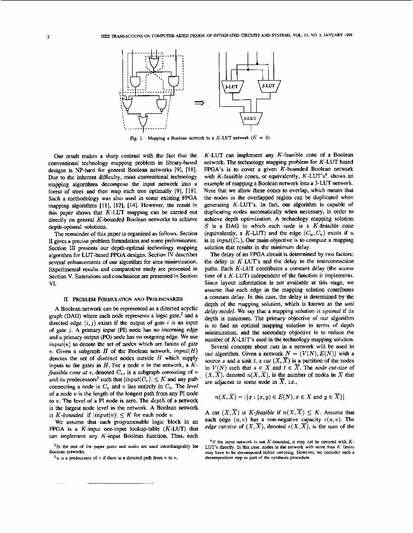
Corollary I : The labels of all the nodes in N can be computed in O(Kmn) time, where n and m are the number of nodes and
In fact, the result in Theorem 1 can be generalized for computing the minimum height K-feasible cut in a general network with arbitrary node labels and edge capacities as follows.
Theorem 2: Given a general network N with a non-negative integer capacity defined on each edge and a non-negative inte- ger label dejined on each node except the sink. For anzposi- tive integer K , a minimum height K-feasible cut ( X , X ) can be found in O(m . min{K, fi} . log L ) time, and a mini- mum height cut ( X , x ) with e ( X , x ) _< K can be found in O(mn log(n*/m) log L ) time, where n and m are the number of the nodes and edges in N , respectively, and L is the number
The proof and the detailed algorithm can be found in [4]. This result has been used for delay-optimal K-LUT technology mapping under arbitrary net-delay models [6] .
edges in N , respectively. 0
of different node labels. 0
3.2. The Mapping Phase The second phase of our algorithm is to generate the K -
LUT’s in the optimal mapping solution. Let L be the set of gates, which are to be implemented using K-LUT’s. Initially, L contains all the PO nodes. We process the nodes in L one by one. For each node Y in L, assume that (X,, xu) is the minimum height K-feasible cut in N, that we have computed in the first phase by the labeling algorithm. We generate a K- LUT w‘ to implement the function of gate w, using the input signals from X , to x,. That is, the K-LUT Y’ includes all the gates in T, and input (U’) = input ( r,). (Since the cut is K-feasible, we have linput(X,)I 5 K.) Then, we update the set L to be ( L - {w})U input (w’). It is possible that a gate w belongs to both xv and Tu for two different gates ‘U
and U in L. In this case, gate w is automatically duplicated and is included in both K-LUT’s w’ and U’. It is also possible that no K-LUT is generated for a gate w since it has been completely covered by the K-LUT’s generated for some of its successors. In general, a K-LUT has to be generated for a gate w if w belongs to input (U’) of some K-LUT U’ which has been generated, since its output signal is required by w’ as input.
The second phase ends when L consists of only PI nodes of the original network. It is clear that at the end of the execution we get a network of K-LUT’s which is logically equivalent to the original network.
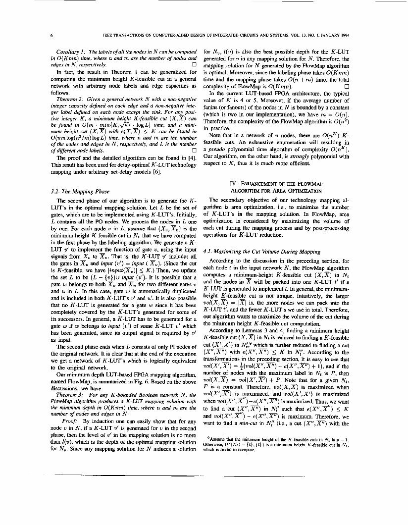
Our minimum depth LUT-based FPGA mapping algorithm, named FlowMap, is summarized in Fig. 6. Based on the above discussions, we have
For any K-bounded Boolean network N , the FlowMap algorithm produces a K-LUT mapping solution with the minimum depth in O(Kmn) time, where n and m are the number of nodes and edges in N .
Pro08 By induction one can easily show that for any node w in N, if a K-LUT w’ is generated for w in the second phase, then the level of w’ in the mapping solution is no more than Z(v), which is the depth of the optimal mapping solution for N,. Since any mapping solution for N induces a solution
Theorem 3:
for N,, Z(w) is also the best possible depth for the K-LUT generated for w in any mapping solution for N . Therefore, the mapping solution for N generated by the FlowMap algorithm is optimal. Moreover, since the labeling phase takes O(Kmn) time and the mapping phase takes O(n + m) time, the total
0 In the current LUT-based FPGA architecture, the typical
value of K is 4 or 5. Moreover, if the average number of fanins (or fanouts) of the nodes in N is bounded by a constant (which is two in our implementation), we have m = O(n) . Therefore, the complexity of the FlowMap algorithm is O(n2) in practice.
Note that in a network of n nodes, there are O ( n K ) K - feasible cuts. An exhaustive enumeration will resulting in a pseudo polynomial time algorithm of complexity O(nK) . Our algorithm, on the other hand, is strongly polynomial with respect to K , thus it is much more efficient.
complexity of FlowMap is O(Kmn).
IV. ENHANCEMENT OF THE FLOWMAP ALGORITHM FOR AREA OPTIMIZATION
The secondary objective of our technology mapping al- gorithm is area optimization, i.e., to minimize the number of K-LUT’s in the mapping solution. In FlowMap, area optimization is considered by maximizing the volume of each cut during the mapping process and by post-processing operations for K-LUT reduction.
4.1. Maximizing the Cut Volume During Mapping
According to the discussion in the preceding section, for each node t in the input network N, the FlowMap algorithm computes a minimum-height K-feasible cut ( X , x) in Nt and the nodes in w will be packed into one K-LUT t’ if a K-LUT is generated to implement t. In general, the minimum- height K-feasible cut is not unique. Intuitively, the larger v o l ( X , x ) = 1x1 is, the more nodes we can pack into the K-LUT t’, and the fewer K-LUT’s we use in total. Therefore, our algorithm wants to maximize the volume of the cut during the minimum height K-feasible cut computation.
According to Lemmas 3 and 4, finding a minimum height K-feasible cut ( X , x) in Nt is reduced to finding a K-feasible cut (XI, x’) in Nl? which is further reduced to finding a cut ( X ” , F ) with e(X”,X”) 5 K in N,”. According to the transformations in the preceding section, it is easy to see that voZ(X’,X’) = ~(woZ(X”,x”) - e ( X ” , F ) + l), and if the number of nodes with the maximum label in Nt is P, then woZ(X,x) = woZ(X’,x’) + P. Note that for a given Nt, P is a constant. Therefore, v o Z ( X , x ) is maximized when wol(X’ ,F) is maximized, and wol(X’ ,F) is maximized when woI(X”, x”) -e(X”, x”) is maximized. Thus, we want to find a cut (X”,x”) in N,” such that e ( X ” , F ) 5 K and woZ(X”, x”) - e(X”, x”) is maximum. Therefore, we want to find a min-cut in N,” (i.e.. a cut (X”,x”) with the
9Assume that the minimum height of the K-feasible cuts in Nt is p - 1. Otherwise, (V( Nt ) - { t }, { t } ) is a minimum height IT-feasible cut in Nt , which is trivial to compute.
CONG AND DING: FLOWMAP: AN O m M A L TECHNOLOGY MAPPING ALGORITHM 7
minimum e ( X ” , X ” ) of the maximum volume.’o First, we give the following characterization of a maximum volume min-cut.
Lemma 5: There is a @que maximum volume min-cut in any netw_ork. Moreover, i f ( X , X ) is the maximum~olume min-cut and (Y,Y) is another min-cut differentfrom ( X , X ) , then X C Y .
Let ( X , X ) and ( Y , y ) be two min-cuts of a given network N . Then, ( X n Y , x U F) is also a min-cut. If ( X , x ) is a maximum volume min-cut, we have 1x1 2 IX U 51, i.e., P Y . Moreover, if (Y ,Y) is also a maximum volume min-cut, then X = 7, which implies X = Y. U
Our algorithm computes a maximum volume min-cut (x”,XII) in N,” as follows: we first compute a maximum flow f in N,”, and obtain the flow residual graph Rf. We then perform a depth-first search in Rf from the source s to find all the nodes reachable from s. These nodes (including s) form the set X”, while all the other nodes form the set X”. The next lemma shows that the min-cut computed by our algorithm indeed has the maximum volume.
Lemma 6: Let Rf be the residual graph of a maximumjlow f. Let X be the set of nodes in Rf reachable from the source s, and x be the set of the remaining nodes. Then, ( X , x ) is a maximum volume min-cut.
Proof: According to the Max-flow Min-cut Theorem 181, [IO], ( X , X ) is a min-cut. Let (Y,F) be the maximum volume min-cut. According to Lemma 5 , If Y # X , then Y c X, and there is a node w E X - Y . Since (Y ,y ) is also saturated by f , and w E P, w is not reachable from s, which is a contradiction. 0
Pro05
x, which implies X
-
Combining Theorem 1 and Lemma 6, we have Theorem: A maximum volume min-cut in N,“ can be found
in O(Km) time, where m is the number of edges in N t . 0 Therefore, FlowMap maximizes the number of gates cov-
ered in each K-LUT by maximizing the volume of each min-cut in N,”. As a result, area minimization is also achieved during depth-optimal mapping in FlowMap.
4.2. Postprocessing Operations for K-LUT Reduction In the preceding subsection, we have described the tech-
niques of minimizing the number of K-LUT’s during the depth-optimal mapping. After obtaining a K-LUT mapping solution using the FlowMap algorithm, we want to further reduce the number of K-LUT’s used in the mapping solution without increasing the depth.
In [3], two depth-preserving operations were developed to minimize the number of K-LUT’s in the mapping solutions of DAG-Map. One is called the predecessor packing. If a K-LUT U has a fanin K-LUT w, w is fanout-free and (Znput({u, w})l 5 K, then w can be merged into U. The predecessor packing operation is shown in Fig. 7. Another operation is called the gate decomposition. If a K-LUT U has two fanin K-LUT’s w and 20, both are fanout-free, and linput({w,w})l 5 K, then w and 20 can be merged into one K-LUT that has a single
lo T ~ I is another reason to compute a min-cut (instead of any cut with e ( X ” , X “ ) 5 K) in N,”: For every signal across the cut in Nt, we need to generate the signal using a K-LUT. Therefore, minimizing the node cut-size in Nt will also lead to reduction of the number of IT-LUT‘s.
algorithm FlowMap /* phase 1: labeling network */ for each PI node v do
T := list of non-PI nodes in topological order. while Tis not empty do
I ( v ) := 0
remove the first node r from T.. construct the network N I ; letp = max(l(u) : U E inpuf(r) 1; transform N , into transform N‘, into KfJ as follows:
by collapsing all nodes in N I with label p into r:
split every node in ( x : x E A’;, x # s, x # f ) into two and connect them with a bridging edge of capacity 1;
assign all non-bridging edges capacity -;
usingthe augmenting path algorithm;
X, := It); I ( r ) : = p + 1
injuce %cut (X, 2) in NI from the cut (X”, 2”) in X I : = X ; I ( r ) : = p
compute a cut (x”, X“) in N”, s.t. e (x”, 2’’) I K
if (r. X ” ) is not found in
else
then
endif endwhile; I* phase 2: generate K-LUTs */ L := list of PO nodes; while L contains non-PI nodes do
take a non-PI node v fmm L; generate a K-LUT v‘ to implement the function of v
L := (L - [ v )) U inpur(v’) such that inpur (v’) = input ( X, );
endwhile end-algorithm;
Fig. 6. Pseudocode of the FlowMap algorithm.
fanout to U, providing that we can carry out the Roth-Karp decomposition [23] on U with respect to its input w and w. The gate decomposition operation is shown in Fig. 8. Clearly, these two operations only take local information into consideration when reducing the K-LUT’s.
In this subsection, we want to generalize the idea of pre- decessor packing so that instead of packing U with one of its fanins into a K-LUT, we try to pack a set of its predecessors (including U), denoted P,, into a single K-LUT. Fig. 9 illustrates the new operation, which is called the $ow-pack. Clearly, we need to guarantee the condition that linput(P,)I 5 K in order to carry out the packing. Let M be the current mapping solution and Mu be the subnetwork of M consisting of K-LUT U and all its predecessors. Then, P, can be packed into a single K-LUT if and only if (V(M,) - P,, Pu) forms a K-feasible cut in Mu. Moreover, the larger lP,l is, the more K-LUT’s we reduce in the mapping solution M. Therefore, we want to find a K-feasible cut with the maximum volume in Mu. The preceding subsection shows that a maximum volume min-cut can be computed efficiently. However, our experimental results showed that using maximum volume min-cut for K-LUT reduction is less effective due to the following reason. The resulting K-LUT network produced by the FlowMap algorithm is usually much denser than the initial 2-input network. Consequently, in many cases, Mu has a unique min-cut (V( Mu) - {U}, {U}). We need to find larger K-feasible cut to overcome this problem.
Since there are only O ( n K ) different K-feasible cuts in a network of size n, a maximum-volume K-feasible cut can

a b c d e f a b c d e f
'- - 1- - - - - '
abed e f
Fig. 7. Predecessor packing (h' = 5).
a b c d e f g c a b e f g d c a b e f g d
Fig. 8. Gate decomposition ( K = 5).
=3
also be determined in O(nK) time by enumerating all the K - feasible cuts. However, this method is too expensive when n is large, even for K = 5. Therefore, we have developed a heuristic algorithm.
We define the rank of a cut (X,x), denoted T ( X , X ) , to be an ordered pair < n(X,W), -wol(X,x) >. The cuts can be ordered according to their ranks under the lexicographic ordering, i.e., for any two cuts (X,x) and (Y ,P) , r ( X , X ) > r(Y,Y) if n ( X , x ) > n(Y,F), or n ( X , X ) = n(Y,P) and w o l ( X , x ) < voZ(Y,B). Clearly, the maximum volume min- cut has the smallest rank.
Given a K-LUT network M and a K-LUT U, our algorithm iteratively computes a sequence of cuts in Mu whose rank
is monotonically increasing, and at each step, we minimize the increase of the rank of the cut. There are two reasons to minimize the rank. First, we want to limit the increase of the node cut-size at each step since we are interested only in K - feasible cuts. Second, for the cuts of the same node cut-size, the smaller the rank is, the larger volume the cut has.
Specifically, we start with the maximum volume min-cut (XO, x~), which has the minimum rank. In the ith iteration (i 2 1). we compute a new cut (Xi,Xi) from the previous cut (Xi-1,Xi-l) in the sequence as follows.
be the nodes in Xi-1 that are adjacent to some node in xi-1. To compute (Xi, Xi), we first collapse all the nodes in Ti-1 into
- -
Let n(X+I,Xi-l) = ki-1, and let w 1 , w 2 , ...,

CONG AND DING FLOWMAP: AN OpIlMAL TECHNOLOGY MAPPING AUjORITHM
5xpl (104)l 26 3 I 2 4 3
TABLE I COMPARISON WITH CHORTLE-D AND DAG-MAP
2 5 3 Ssym (200) 9symml (191) C499 (658) C880 (548) aIu2 (393) a h 4 (726) apex6 (779) apex7 (247) count (216) des (3263) duke2 (392) misex l (57) rd84 (141) rot (647) vg2 (120) z4mI (48)
Total
63 59
382 329 227 500 308 108 91
2086 241
19 61
326 55 25
4906
5 5 6 8 9 10 4 4 4 6 4 2 4 6 4 3 87
61 5 58 5
207 5 243 8 169 8 305 10 266 4 91 4 81 4
1433 6 192 4
15 2 43 4
292 6 4 6 4 17 3
3543 85 Comparison 1+50.4% +4.8% I +8.6% +2.4%
We also tested the above three algorithms on the inpu
61 5 58 5
154 5 232 8 162 8 268 10 257 4 89 4 76 3
1308 5 187 4 15 2 43 4
268 6 45 4 13 3
3261 83 1 1
ietworks used by DAG-Map in [3]. The results showed that compared to FlowMap, DAG- Map used 5.6% more 5-LUT’s and had 1.2% larger network depth, while Chortle4 used 52.2% m m SLUT‘S and had 10.7% larger network depth. FlowMap produced consistent better results than the other two algorithms.
the sink U. Denote the reduced network as MA. Moreover, let M;(j ) denotes the network obtained from M t by collapsing wj (1 5 j 5 ki- 1) into the sink U. We compute the maximum volume min-cut (Y,,Fj) in ~ : ( j ) for every j , 1 5 j I ki-1. Let k, be the minimum node cut-size of these cuts. Moreover, among those cuts that have node cut-size k,, let (Y,y) be the one of maximum volume. Let X, = Y, and X, = V ( M ~ > - X,, we accept (X,,Xi) as the resulting cut of the ith iteration.
It can be shown [4] that the cut (Xi, Ti) has the following properties:
-
- (1) WO~(X~,X*) > vol(Xa-1, - Xi-1); (2) n(X,,_x,) > ~(Xd-A-1); ancl (3) r(X,,Xa) 5 r(X,X) for any cut (X,X) such that
Therefore, the cut computed at each step is locally optimal. This iterative procedure ends when at some step 1, (Xl, Xl)
is not K-feasible. The last K-feasible cut, (Xl-l,Xl-~), computed in the sequence, is used in the flow-pack algorithm such that Pu = Xl-1. Since the node cut-size is monotonically increasing, we have the number of iterations E 5 K. Moreover, each iteration consists of at most K maximum volume min-cut computations, each of time complexity O(Km) (Theorem 4). Therefore, the time complexity for carrying out the flow-pack algorithm at each node is bounded by O(K3m), where m is the number of edges in the K-LUT network.
The flow-pack algorithm is implemented as a pst-proc- essing step of FlowMap. During the post-processing phase, we first carry out the gate-decomposition operation. (In fact, we carry out a maximum set of gate-decomposition oper- ations simultaneously by computing a maximum cardinal-
X C Xa-1.
TABLE II COMPARISON WITH MIS-PGA-DELAY ALGORITHM
MIS-pgadelay FlowMap #LuT’s depth #LuT’s depth Circuit
21 22 3 5xpl Ssym 9symml c 4 9 9 C880 alu2 a h 4 apex6 apex7 count des duke2 misex l rd84 Tot
vg2 z4mI Total Comparison
7 3 7 2
199 8 259 S 122 c 155 11 274 5
95 4 81 4
1397 11 164 c
17 2 13 ?
322 5 39 4 10 4
3182 9c +9.8% +7.1’?4
60 55 68
124 155 253 238 79 31
1310 174 16 46
234 29
5 2899
I
5 5 4 8 9 9 5 4 5 5 4 2 4 7 3 2
84 1 1
ity matching among all pairs of gates which are eligible for gate-decomposition. Details of the matching based gate- decomposition algorithm can be found in [3].) Then, we apply the flow-pack operation to each K-LUT U in the mapping solution so that U is collapsed with a maximal subset of its predecessors into a single K-LUT.
The advantage of the flow-pack operation is clear: the flow-pack operation takes the information about the entire sub- network Mu into consideration, while the predecessor packing examines only the nodes adjacent to U locally. Therefore, in general flow-pack leads to more substantial reduction of the number of K-LUT’s. Our experimental results show that the flow-pack operation alone reduced the number of K-LUT’s by 13.5% on average.
v. EXPERIMENTALRESULTS
We have implemented the FlowMap algorithm and its preprocessing and post-processing steps using the C language on Sun SPARC workstations. We used input/output routines and general utility functions provided by MIS [2] in our implementation. Given a general Boolean network as input, we first decompose it into a 2-input network of simple gates as described in [3]. We then apply the FlowMap algorithm to obtain a minimum depth K-LUT mapping solution. Next, we perform a matching-based gate-decomposition procedure on the K-LUT network, followed by the flow-pack operation to reduce the number of K-LUT’s in the mapping solution. We chose the size of the K-LUT to be K = 5, reflecting, e.g., the XC3000 FPGA family produced by Xilinx [28]. We tested FlowMap on a number of MCNC benchmark examples and the results were compared with those produced by Chortle-d [13], MIS-pga-delay [21], and DAG-Map [3]. The results are shown in Tables I and 11.
In Table I, we used the initial networks provided by Robert Francis, which were used by Chortle-d to obtain the results
10 IEEE TRANSACTIONS ON COMPUTER-AIDED DESIGN OF INTEGRATED CIRCUITS AND SYSTEMS, VOL. 13, NO. 1, JANUARY 1994
60 5 55 5 68 4
124 8 155 9 253 9 238 5 79 4 31 5
1310 5 174 4 16 2 46 4
234 7 29 3 5 2
2899 84 1 1
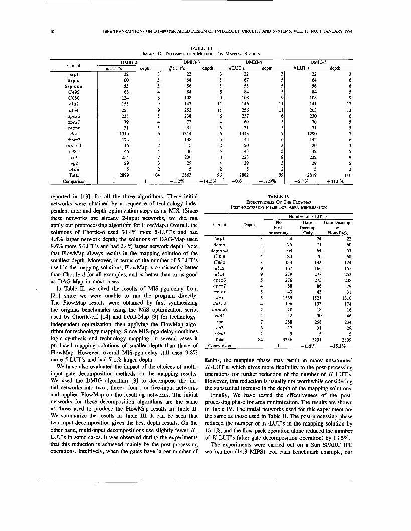
TABLE III IMPACT OF DECOMP~SITTON METHODS ON ~~APPING RESULTS
64 5 56 5 84 5
108 9 143 11 252 11 238 6 72 4 31 5
1314 6 148 5 15 2 46 5
236 8 29 4
5 2 2863 96
-1.2% +14.3%
DMIG-3 DMIG-4 DMG-5 depth #LUT’s Circuit
5xpl S s y m
9 s y m m l c 4 9 9 C880 alu2 aIu4
apex6 apex7 count
des duke2
m i s e x l rd84
vg2 z 4 m l Total
Comparison
T O t
depth #LuT’s depth # L W s depth 22 31 22 31 22 31 22 3
reported in [13], for all the three algorithms. These initial networks were obtained by a sequence of technology inde- pendent area and depth optimization steps using MIS. (Since these networks are already 2-input networks, we did not apply our preprocessing algorithm for FlowMap.) Overall, the solutions of Chortle-d used 50.4% more 5-LUT’s and had 4.8% larger network depth; the solutions of DAG-Map used 8.6% more 5-LUT’s and had 2.4% larger network depth. Note that FlowMap always results in the mapping solution of the smallest depth. Moreover, in terms of the number of 5-LUT’s used in the mapping solutions, FlowMap is consistently better than Chortle-d for all examples, and is better than or as good as DAG-Map in most cases.
In Table 11, we cited the results of MIS-pga-delay from [21] since we were unable to run the program directly. The FlowMap results were obtained by first synthesizing the original benchmarks using the MIS optimization script used by Chortle-crf [14] and DAG-Map [3] for technology- independent optimization, then applying the FlowMap algo- rithm for technology mapping. Since MIS-pga-delay combines logic synthesis and technology mapping, in several cases it produced mapping solutions of smaller depth than those of RowMap. However, overall MIS-pga-delay still used 9.8% more 5-LUT’s and had 7.1% larger depth.
We have also evaluated the impact of the choices of multi- input gate decomposition methods on the mapping results. We used the DMIG algorithm [3] to decompose the ini- tial networks into two-, three-, four-, or five-input networks and applied FlowMap on the resulting networks. The initial networks for these decomposition algorithms are the same as those used to produce the FlowMap results in Table 11. We summarize the results in Table III. It can be seen that two-input decomposition gives the best depth results. On the other hand, multi-input decompositions use slightly fewer K - LUT’s in some cases. It was observed during the experiments that this reduction is achieved mainly by the post-processing operations. Intuitively, when the gates have larger number of
67 5 55 5 84 5
108 9 146 11 256 11 237 6 69 5 31 5
1343 7 144 c 20 3 43 5
29 3 5 2
2882 99
223 a
-0.6 +17.9%
64 6 56 6 84 5
108 9 141 13 263 13 230 6 70 5 31 5
1290 7 142 6 20 3 42 5
222 9 29 5 5 2
2819 110 -2.7% +31.0%
TABLE IV EFFEcIlvENEsS OF THE FLOWMAP
POST-PROCESSING PHASE FOR AREA M~IMIZATION
Number of 5-LUT’s No Gate- Gate-Decomp.
Post- Decomp. & Circuit Depth
5xpl 3 24 24 22 S s y m 5 76 71 60
Ssymml 5 68 64 55 c 4 9 9 4 80 76 68 C880 8 133 133 124 alu2 9 167 166 155 alu4 9 279 277 253
apex6 5 276 273 238 apex7 4 88 88 79 count 5 43 43 31
des 5 1539 1521 1310 duke2 4 196 193 174
m i s e x l 2 20 18 16 rd84 4 52 50 46 rot 7 258 258 234 vg2 3 32 31 29
z 4 m l 2 5 5 5 Total 84 3336 3291 2899
processing Only How-Pack
Comparison 1 -1.4% -15.1%
fanins, the mapping phase may result in many unsaturated K-LUT’s, which gives more flexibility to the post-processing operations for further reduction of the number of K-LUT’s. However, this reduction is usually not worthwhile considering the substantial increase in the depth of the mapping solutions.
Finally, We have tested the effectiveness of the post- processing phase for area minimization. The results are shown in Table IV. The initial networks used for this experiment are the same as those used in Table 11. The post-processing phase reduced the number of K-LUT’s in the mapping solution by 15.1%, and the flow-pack operation alone reduced the number of K-LUT’s (after gate-decomposition operation) by 13.5%.
The experiments were carried out on a Sun SPARC IPC workstation (14.8 MIPS). For each benchmark example, our
CONG AND DING: FLOWMAP AN OF’TIMAL TECHNOLOGY MAPPING ALGORITHM 11
system took less than one minute of CPU time (in most cases a few seconds). Therefore, it is much faster than the Boolean optimization based algorithms.
VI. CONCLUSION AND FUTURE EXTENSIONS In this paper, we have presented a technology mapping
algorithm named FlowMap for depth minimization in LUT- based FPGA designs, which is optimal for any K-bounded Boolean network. It is based on efficient computation of minimum height K-feasible cuts in a network. A number of area optimization techniques also allow FlowMap to reduce the number of K-LUT’s significantly. Compared to the existing LUT-based FPGA technology mapping algorithms for delay optimization, FlowMap reduces the depth of the LUT network by up to 7% and reduces the number of LUT’s by up to 50%. FlowMap takes less than one minute of CPU time for each of the benchmarks in our test suite.
One extension is to use a more general delay model other than the unit delay model. For example, Chan, Schlag, and Kong [25] used the nominal delay model in FPGA designs where the interconnection delay of a signal net is estimated by the number of fanouts of the net. Their results showed that the nominal delay model estimates the interconnection delay quite well. Based on Theorem 2, we have generalized the FlowMap algorithm to perform delay-optimal mapping under arbitrary net-delay models, including the nominal delay model [6].
Another extension is to combine area and depth optimization in the mapping procedure. Note that the depth of every node is minimum in a FlowMap mapping solution, while in fact only the depths of the nodes on the critical paths need to be minimized to guarantee depth-optimal mapping. The slacks of the non-critical nodes can be utilized for area minimization without affecting the depth optimality. This method can be further extended to the general problem of area minimization under given depth constraint. Based on a set of depth relaxation operations defined for non-critical nodes, We have developed an algorithm that can produce a spectrum of area-optimized mapping solutions for different depth constraints, yielding smooth area and depth trade-off in LUT-based FPGA designs [5].
The area-optimal mapping problem for LUT-based FPGA designs is still open. Based on the concept of the maximum fanout-free cones, introduced in [5] we have developed a polynomial time algorithm for area-optimal K-LUT mapping without node duplication for any fixed K [5].
ACKNOWLEDGMENT
The authors thank Professor Jonathan Rose, Robert Fran- cis, and Rajeev Murgai for their assistance in the authors’ comparative study.
REFERENCES
[l] N. Bhat. and D. Hill, “Routable technology mapping for FPGA’s,” in First Inr. ACMISIGDA Workshop on Field Programmable Gate Arrays, Feb. 1992, pp. 143-148.
[2] R. K. Brayton, R. Rudell, and A. L. Sangiovanni-Vincentelli, “MIS: A
multiple-level logic optimization,” IEEE Trans. Computer-Aided Design,
[3] K. C. Chen, J. Cong, Y. Ding, A. B. Kahng, and P. Trajmar, “DAG- map: Graph-based FPGA technology mapping for delay optimization,” IEEE Design and Test of Computers, pp. 7-20, Sept. 1992.
[4] J. Cong and Y. Ding, “An optimal technology mapping algorithm for delay optimization in lookup-table based FPGA designs,” Tech. Rep. CSD-920022, UCLA Computer Science Dept., May 1992.
151 J. Cong and Y. Ding, “On area/depth trade-off in LUT-based FPGA technology mapping,” in Proc. 30th ACMIIEEE Design Automation Conf., June 1993, pp. 213-218.
[6] J. Cong, Y. Ding, T. Gao, and K. Chen, “An optimal performance-driven technology mapping algorithm for LUT based FPGA’s under arbitrary net-delay models,” in Proc. 1993 Inr. Conf. on Computer-Aided Design and Computer Graphics, Aug. 1993, pp. 599-603.
[7] J. Cong, A. Kahng, P. Trajmar, and K. C. Chen, “Graph based FPGA technology mapping for delay optimization,” in ACM Int. Workshop on Field Programmable Gate Arrays, Feb. 1992, pp. 77-82.
[8] T. Cormen, C. Leiserson, and R. Rivest, Algorithms. Cambridge, MA: MIT Press, 1990.
[9] E. Detjens, G. Gannot, R. Rudell, A. Sangiovanni-Vincentelli, and A. Wang, “Technology mapping in MIS,” in Proc. IEEE Int. Conf. Computer-Aided Design, 1987, pp. 1 1 6 1 19.
[lo] L. R. Ford and D. R. Fulkerson, Flows in Nefworks. Princeton, N J Princeton Univ. Press, 1962.
[ 111 R. J. Francis, J. Rose, and K. Chung, “Chortle: A technology mapping program for lookup table-based field programmable gate arrays,” in Proc. 27th ACMIIEEE Design Automation Conf., 1990, pp. 613-619.
[12] R. J. Francis, J. Rose, and 2. Vranesic, “Technology mapping for delay optimization of lookup table-based FPGA’s,” in MCNC Logic Synthesis Workshop, 1991.
[13] R. J. Francis, J. Rose, and Z. Vranesic, “Technology mapping of lookup table-based FPGA’s for performance,” in Proc. IEEE Int. Cor$ Computer-Aided Design, Nov. 1991, pp. 568-571.
[14] R. J. Francis, J. Rose, and Z. Vranesic, “Chortle-cxf Fast technology mapping for lookup table-based FPGA’s,” in Proc. 28th ACMIIEEE Design Automation Conf., 1991, pp. 613-619.
151 D. Hill, “A CAD system for the design of field programmable gate ar- rays,” in Proc. ACMIIEEE Design Automation Conf. 1991, pp. 187-192.
161 D. A. Huffman, “A method for the construction of minimum redundancy codes,’’ in Proc. IRE 40, 1952, pp. 1098-1101.
171 K. Karplus. “Xmap: A Technology mapper for table-lookup field- programmable gate arrays,” in Proc. 28th ACMIIEEE Design Automation Cor$, 1991, pp. 24CK243.
181 K. Keutzer, “DAWN: Technology binding and local optimization by DAG matching,” in Proc. 24th ACMIIEEE Design Automation Conf.,
[19] E. L. Lawler, K. N. Levitt, and J. Turner, “Module clustering to minimize delay in digital networks,” IEEE Trans. Computers, vol C-18,
[20] R. Murgai, et al., “Logic synthesis algorithms for programmable gate arrays,” in Proc. 27th ACMIIEEE Design Automation Conf., 1990, pp. 620-625.
[21] R. Murgai, N. Shenoy, R. K. Brayton, and A. Sangiovanni-Vincentelli, “Performance directed synthesis for table look up programmable gate arrays,’’ in Proc. IEEE Int. Conf. Computer-Aided Design, Nov. 1991,
[22] R. Murgai, N. Shenoy, R. K. Brayton, and A. Sangiovanni-Vincentelli, “Improved logic synthesis algorithms for table look up architectures,” in Proc. IEEEInt. Conf. Computer-Aided Design, Nov. 1991, pp. 564-567.
[23] J. P. Roth and R. M. Karp, “Minimization over Boolean graphs,” IBM J. Res. Devel., pp. 227-238, Apr. 1962.
[24] P. Sawkar and D. Thomas, ‘Technology mapping for table-look-up based field programmable gate arrays,’’ in ACMISIGDA Workshop on Field Programmable Gate Arrays, Feb. 1992, pp. 83-88.
[25] M. Schlag, P. Chan, and J. Kong, “Empirical evaluation of multilevel logic minimization tools for a field programmable gate array tech- nology,” inProc. 1st Int. Workshop on Field Programmable Logic and Applications, Sept. 1991.
[26] M. Schlag, J. Kong, and P. K. Chan, “Routability-driven technology mapping for lookup table-based FPGA’s,” in Proc. 1992 IEEE Int. Conf. Computer Design, Oct. 1992.
[27] N. S. Woo, “A heuristic method for FPGA technology mapping based on the edge visability,” in Proc. 28th ACMIIEEE Design Automation Conf., 1991, pp. 248-251.
[28] Xilinx, The Programmable Gate Array Data Book. San Jose, CA: Xilinx, 1992.
pp. 1062-1081, NOV. 1987.
1987, pp. 341-347.
pp. 47-57, Jan. 1969.
pp. 572-575.

12 IEEE TRANSACXIONS ON COMPUTER-AIDED DESIGN OF INTUjRATED CIRCUITS AND SYSTEMS, VOL. 13, NO. 1. JANUARY 1994
Jason (Jingsheng) Cong (S’SS-M’W) received the B. S . degree in computer science from the Peking University in 1985. He received the M. S. degree and Ph. D. degree in computer science from the University of Illinois at Urbana-Champaign in 1987 and 1990, respectively.
Currently, he is an assistant professor in the Computer Science Department of University of Cal- ifornia, Los Angeles. From 1986 to 1990, he was a research assistant in the Computer Science Depart- ment of the University of Illinois. He worked at the
Xerox Palo Alto Research Center in the summer of 1987. He worked at the National Semiconductor Corporation in the summer of 1988. His research interests include computer-aided design of VLSl circuits, fault-tolerant design of VLSl systems, and design and analysis of efficient combinatorial and geometric algorithms. He has published over fifty research papers in these fields.
Dr. Cong received the Best Graduate Award from the Peking University in 1985. He was awarded a DEC Computer Science Fellowship in 1988. He received the Ross J. Martin Award for Excellence in Research from the University of Illinois at Urbana-Champaign in 1989. He received the National Science Foundation Research Initiation Award in 1991, and the National Science Foundation Young Investigator Award in 1993. He has served on the program committees of several VLSI CAD conferences. He was the chairman of the 4th ACWSIGDA Physical Design Workshop.
Yuzheng Ding received the B. S. degree in com- puter science from Peking University, and the M. S. degree in computer science from Tsinghua Uni- versity, both in Beijing, China. Currently he is a research assistant in the Department of Computer Science of University of California, Los Angeles, where he is pursuing his Ph. D. degree.
His research interests include computer-aided de- sign of VLSl circuits, design and analysis of data structu~s and algorithms, and database systems.
Mr. Ding is a member of ACM.