
systems in practical USe,
9
CHAPTER XXI. INTERCOMMUNICATION IN TRAINS 245. IN 1867 a circular was issued by the Board of Trade to the Railway companies, asking them to confer on the subject of passenger and guard communication. In 1868, an Act was passed, ordering that after the 1 st of April 1869, every train travelling over twenty miles without stopping should be provided with a means of communication between the passengers and the guards of the train. In February, 1869, the Board of Trade allowed the cord system—a mechanical arrangement—to be adopted, conditionally. In August, 1872, Captain Tyler, in a report upon the subject, addressed to the Board of Trade, says, "the result of the working of the cord system has not been satisfactory," and in his report of August, 1871, shows that it is " hardly an economical system, though cheap in first cost." Captain (now Sir Henry) Tyler thus sets forth the requirements of such a communication. " The apparatus, of whatever nature, shall be as far as possible simple and self-adjusting; it shall, after disuse for a length of time, be efficient when tested; it shall appeal unmistakably to the eye and ear of the driver on the engine, and of the guard in each part of the train • it shall be equally efficient in very long or in short trains; shall be adapted to the attachment or detachment of carriages on a journey; shall be independent of the state of the rails or the state of the atmosphere; and, while not liable to be accidentally set in motion, shall be easily acted on when required." " An electrical apparatus appears on the whole to offer the best chance of success." The systems of electrical communication which had been introduced in 1873 were four, viz.:— 1. Preece's, introduced on the South-Western Rail- way in 1864. 2. Walker's, introduced on the South-Eastern Rail- way in 1866. 3. Varley's, introduced on the North-Western Rail- way in 1866. 4. Binney's, introduced on the Great-Eastern Rail- way in 1872. The principle of Preece's and Walker's is identical, in- asmuch as each instrument has a battery, the similar negative poles of which are joined to a connecting wire running throughout the length of the whole train, whilst the opposite or positive poles are connected with the earth, thus setting up a state of electrical equilibrium which may be disturbed at will by placing the train wire to earth, when the current from each battery will pass through the instruments in connection with it. 246. Of the systems mentioned there now remain but two in practical USe, viz., Walker's, on the South-Eastern Railway, and Preece's, on the London and South-Western. The former railway maybe said to have been the pioneer in the thorough adootion of electrical
Transcript of systems in practical USe,

C H A P T E R X X I .
I N T E R C O M M U N I C A T I O N I N T R A I N S
2 4 5 . I N 1867 a circular was issued b y the B o a r d of T r a d e to the R a i l w a y companies , asking them to confer on the subject of passenger and guard communica t ion .
In 1868, an A c t was passed, ordering that after the 1 st o f Apr i l 1869, every train travell ing over twenty miles without s topping should b e provided with a means of communica t ion be tween the passengers and the guards o f the train.
I n February, 1869, the Board of T r a d e a l lowed the cord sys tem—a mechanica l ar rangement—to b e adopted, conditionally.
I n Augus t , 1872 , Capta in Ty le r , in a report upon the subject, addressed to the Board of T r a d e , says, " t h e result of the working o f the cord system has not been satisfactory," and in his report of Augus t , 1 8 7 1 , shows that it is " hardly an economica l system, though cheap in first cost ."
Cap ta in (now Sir Hen ry ) T y l e r thus sets forth the requirements o f such a communicat ion.
" T h e apparatus, o f whatever nature, shall be as far as poss ib le simple and self-adjusting; it shall, after disuse for a l eng th o f t ime, be efficient when t e s t e d ; it shall
appeal unmis takably to the eye and ear of the driver on the engine, and of the guard in each part of the train • it shall be equal ly efficient in very long or in short t ra ins; shall b e adapted to the at tachment or detachment o f carriages on a j o u r n e y ; shall be independent of the state of the rails or the state o f the a tmosphe re ; and, while not l iable to b e accidenta l ly set in motion, shall be easily acted on when required."
" A n electr ical apparatus appears on the whole to offer the best chance of success."
T h e systems of electrical communicat ion which had been in t roduced in 1873 were four, v i z . : —
1. Preece ' s , in t roduced on the South-Western Railw a y in 1864.
2. Walker ' s , in t roduced on the South-Eastern Rai l w a y in 1866.
3. Var l ey ' s , in t roduced on the North-Western Rai l w a y in 1866.
4. Binney ' s , introduced on the Great-Eastern Rai l w a y in 1872 .
T h e principle o f Preece ' s and Walker ' s is identical, inasmuch as each instrument has a battery, the similar negat ive poles of which are jo ined to a connect ing wire running throughout the length of the whole train, whilst the opposi te or posi t ive poles are connected with the earth, thus setting up a state of electrical equilibrium which m a y b e disturbed at wil l b y p lac ing the train wire to earth, when the current from each battery will pass through the instruments in connect ion with it.
246. O f the systems ment ioned there now remain but two in practical USe, v iz . , Walker 's , on the South-Eastern Ra i lway , and Preece 's , on the London and South-Western. T h e former railway m a y b e said to have been the pioneer in the thorough adootion of electrical

248. T h e principle involved in this system is illustrated by F ig . 136 .
F I G . 136.
A is a wire passing throughout the train, />, // , b2 are branch wires from it to commutators e, e', e2, which are also in connect ion with the " earth " wire B . A t c« c! c2.
train communica t ion ; for in the face o f the very general preference expressed b y the railway companies ' representatives for the cord system, it yet adhered to the electrical, and at the present t ime the greater portion, if not the whole , o f its passenger rolling-stock is fitted with it.
247. T h e desirability of a uniform system wil l b e evident to the most casual observer. T h e connect ion be tween the various rai lway systems is now so comple te , that the interchange of coaches be tween system and system is a frequent occurrence. I f one system were worked upon a me thod entirely different in its principle to that adopted on any other line, it is evident that to afford the occupants of a c o a c h be longing to such system, travell ing over another system, its advantages, some special provision would have to b e made . I t is thus that a uniform system is desirable, and this extends not only to the principle upon which it is worked , but also to the method o f coupl ing-up the coaches and other veh ic les which may be in t roduced in the train.
Preecis System.
are similar branch wires communicat ing with a bell , the other side o f which is in connect ion with the zinc po le of a battery, the copper pole o f which is to earth. F r o m either side of the bel l wires are led to commutators d, df, d2, which, in c o m m o n with those at e, stand, normally, open.
N o w if all the batteries are o f equal power, and no leakage be tween the wire A and the earth exists, no current will pass, for the several forces will be in contention as represented b y the arrows, and naturally, if the equilibrium be true, no influence will b e exerted on the apparatus. But n o w let the commutator , e, be turned so as to br ing the two wires, in connect ion with it, together. T h e equil ibrium will b e at once destroyed, and the battery current from f2 will find a circuit through e', b', c2, and the bell , which it will ring. T h e current from / ' will in l ike manner pass through e, b\ c\ and its bell, which it wil l also r i n g ; whilst / will also find a similar circuit, r inging the bel l in connect ion with it. T h u s each be l l will be actuated and set in motion b y the single connec t ion at e, and the same would be the case if either e or e2 were operated.
In order to apply this to a railway train we have but to imagine b, b', b2, to be carriages, and c, c\ c2 the engine and guards ' vans compos ing the train. E a c h van is fitted with a c o m m u n i c a t o r , d, d', d2, so that the one guard may communica te with the other or with the engine-driver. Th i s communica tor is usually a bel l -key (§ 1 1 4 ) , which is connec ted up as shown in F ig . 137 . Normal ly the lever of it forms contac t with the upper contact g. O n being pressed down however it l eaves g, and makes contact with h. I n this condi t ion the battery / and its bel l are disconnected, and the line wire, A , p laced in circuit with the earth B .
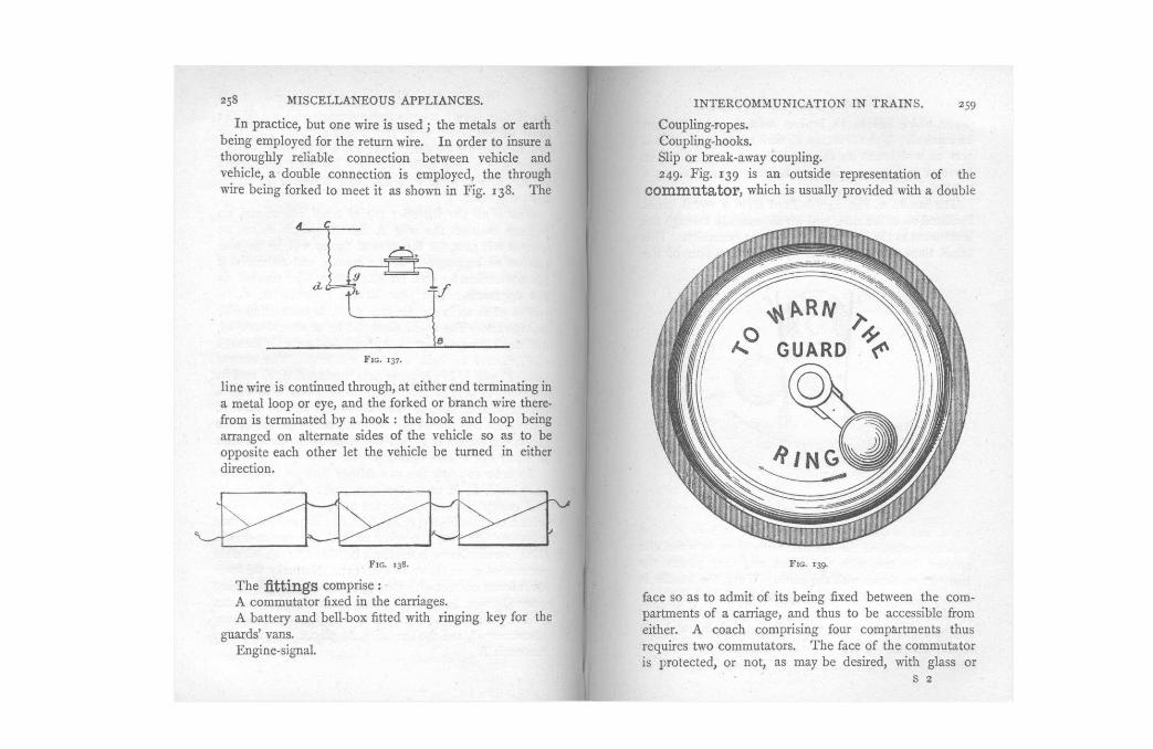
F I G . 137.
l ine wire is continued through, at either end terminating in a metal loop or eye, and the forked or branch wire therefrom is terminated b y a hook : the h o o k and loop being arranged on alternate sides o f the vehic le so as to be opposite each other let the vehic le be turned in either direction.
F I G . 138.
T h e fittings comprise : A commuta tor fixed in the carriages. A battery and bel l -box fitted with r inging k e y for the
guards ' vans. Engine-signal .
F I G . 139.
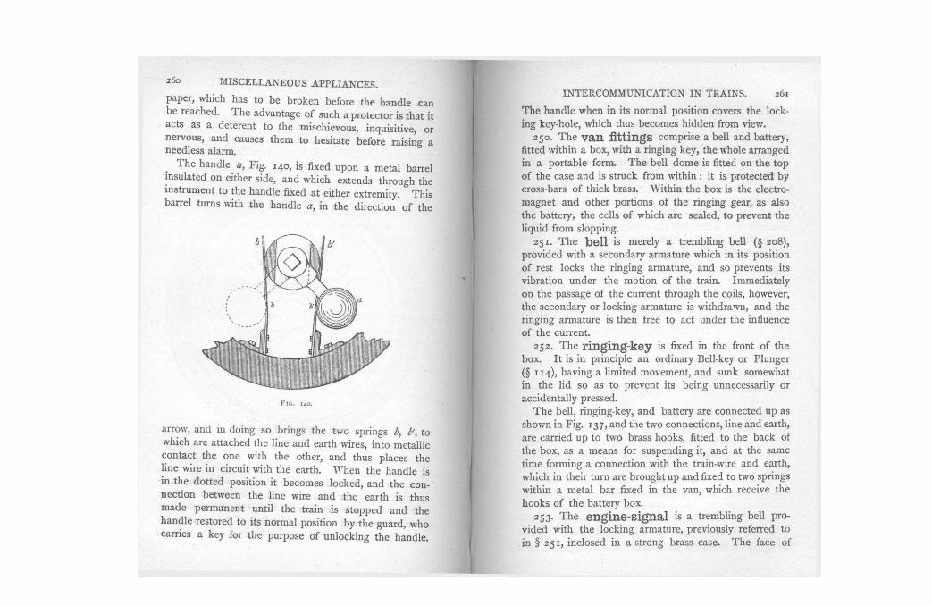
face so as to admit of its be ing fixed between the c o m partments o f a carriage, and thus to be accessible from either. A coach compris ing four compartments thus requires two commutators . T h e face o f the commuta to r is protected, or not, as may b e desired, with glass or
s 2
Coupl ing-ropes . Coupl ing-hooks . Slip or break-away coupling. 249. F ig . 139 is an outside representation of the
Commutator, which is usually provided with a double
I n practice, but one wire is u s e d ; the metals or earth be ing employed for the return wire. I n order to insure a thoroughly reliable connect ion be tween vehic le and vehic le , a double connec t ion is employed, the through wire be ing forked to meet it as shown in F i g . 138. T h e
F I G . 1 4 0 .
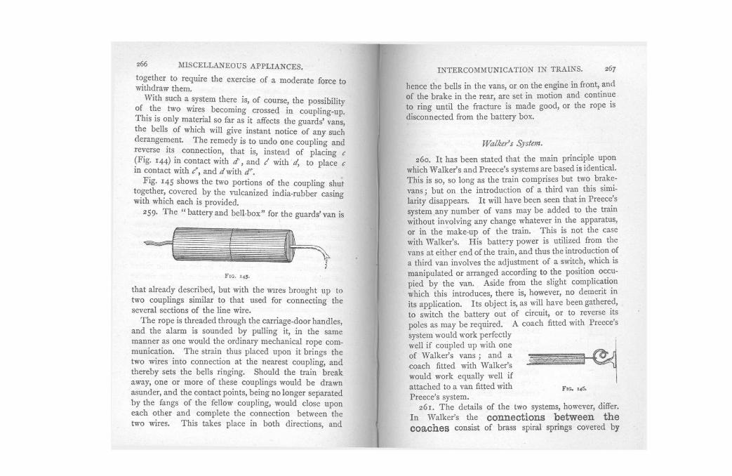
arrow, and in doing so brings the two springs b, b', to which are at tached the line and earth wires, into metall ic contac t the one with the other, and thus p laces the line wire in circuit with the earth. W h e n the handle is in the dot ted posit ion it becomes locked , and the connec t ion be tween the line wire and the earth is thus made permanent until the train is s topped and the handle restored to its normal posit ion b y the guard, w h o carries a key for the purpose o f un lock ing the handle.
T h e handle when in its normal position covers the locking key-hole , which thus becomes h idden from view.
250. T h e van fittings comprise a bell and battery, fitted within a box , with a ringing key , the whole arranged in a portable form. T h e bel l dome is fitted on the top of the case and is struck from within : it is protected b y cross-bars of thick brass. Within the box is the electromagnet and other portions o f the ringing gear, as also the battery, the cel ls o f which are sealed, to prevent the liquid from slopping.
2 5 1 . T h e bell is merely a t rembling bel l (§ 208), provided with a secondary armature which in its position o f rest locks the ringing armature, and so prevents its vibrat ion under the mot ion o f the train. Immediate ly on the passage o f the current through the coils, however , the secondary or lock ing armature is withdrawn, and the r inging armature is then free to act under the influence of the current.
252. T h e ringing-key is fixed in the front o f the box . I t is in principle an ordinary Bel l-key or P lunger (§ 1 1 4 ) , hav ing a limited movement , and sunk somewhat in the l id so as to prevent its be ing unnecessarily or accidenta l ly pressed.
T h e bel l , ringing-key, and battery are connec ted up as shown in F ig . 137 , and the two connections, line and earth, are carried up to two brass hooks , fitted to the b a c k of the box , as a means for suspending it, and at the same t ime forming a connec t ion with the train-wire and earth, which in their turn are brought up and fixed to two springs within a metal bar fixed in the van, which receive the hooks o f the battery box .
253. T h e engine-Signal is a trembling bel l prov ided with the lock ing armature, previously referred to in § 2 5 1 , inclosed in a strong brass case. T h e face of
paper, which has to be b roken before the handle can b e reached. T h e advantage of such a protector is that it acts as a deterent to the mischievous, inquisitive, or nervous, and causes them to hesitate before raising a needless alarm.
T h e handle a, F ig . 140, is fixed upon a meta l barrel insulated on either side, and wh ich extends through the instrument to the handle fixed at either extremity. T h i s barrel turns with the handle a, in the direct ion o f the

F I G . 141.
a stiff flat spring, a, wh ich keeps the eye c, pressing firmly against the hook-p iece A , and so insures g o o d metal l ic contact . T h e hook-piece A is securely fastened to the buffer-beam of the vehic le , as is also the coupl ing-rope B , the end of which is formed into a knot , F i g . 142 , so as to prevent its withdrawal from the cap F , which is p rov ided with a hook G , for the accommoda t ion o f the eye terminating the rope, when not in use.
256. F ig . 143 represents the slip or break-away Coupling, which may be used at discretion. W h e r e employed it takes the p lace o f the hook B , F i g . 1 4 1 . T h e
I N T E R C O M M U N I C A T I O N IN T R A I N S . 263
stud C is connec ted to the earth-wire, and the line-wire to
the h o o k A . T h i s hook works upon two bearings and is
impelled, b y a powerful spiral spring, to rest against C .
F I G . 143.
down, B wil l b e released, and A will then fly back , mak ing contac t wi th C , thereby placing the line in connec t ion with the earth and starting the bells r inging.
it is p rov ided with a small flap, which when the be l l is rung is released and falls down, presenting to the v iew of the engine-driver the instruction " S T O P . "
254. T h e engine communicator m a y b e in circuit with the whole of the train apparatus, or with the first van only .
255. T h e COUpling-ropeS, F i g . 1 4 1 , are formed of three stranded copper wires, e, insulated with india-rubber d, and c o v e r e d with a thick plai t ing o f hemp. T o the insulated wire is a t tached the eye c required to m a k e the connect ion with the h o o k A on the next carriage. T h i s h o o k is made of brass or gun metal , and is p rov ided with

264 M I S C E L L A N E O U S A P P L I A N C E S .
A s this wil l occur with bo th couplings (F ig . 138) the bel ls in bo th portions o f the train and that on the engine wil l be set ringing, and cont inue to do so, so long as A remains in contact with C .
Electrical Rope Communication.
257. Recogn i s ing the necessi ty o f some means for establishing a temporary m o d e o f communica t ion , such as can b e a t tached to a made-up train at a moment ' s not ice , M r . Preece , in conjunct ion with Mr . C . Golds tone and others interested in the subject, have devised an electrical rope communicat ion, which can b e appl ied to
F I G . 144.
a train with all the facility and expedi t ion at tending the application o f the ordinary mechanica l rope arrangement.
I n the system just described, but one line wire passes through the train, the rails and earth be ing used for the return wire. I n the electrical rope system the metals and the earth are replaced b y a wire. T h e " rope " is thus formed o f two insulated wires, which are cove red with h e m p in the usual manner, and which , when thus laid up, form a rope o f some quarter inch in diameter.
258. T h e rope thus arranged is d iv ided into sections o f a carriage length, the extremities of which are fitted with connect ing p ieces or couplings similar to that represented in F ig . 144 .
I N T E R C O M M U N I C A T I O N IN T R A I N S . 265 a, b, are two flat springs fixed to a hol low b l o c k of
ebonite, g, which is secured b y a sheathing o f tin. T o each spring is fitted a three-sided p iece o f ebonite, c, d, somewhat reduced in substance at their extremities ; and on the alternate side o f each of these is fixed a surface piece o f brass terminating in a raised point, as seen at f. T h e communica t ing wires are brought through the eboni te b l o c k g, and at tached, one to each o f the meta l surface p ieces .
T h e tendency o f the springs a, b, is towards each other, and thus when nothing is in terposed to prevent it, the contact points at f are in metal l ic circuit.
B u t i f now a similar arrangement be presented to that descr ibed, in such a manner that its fangs shall intersect those o f F i g . 144, and they be forced together, the contact studs wi l l b e c o m e separated, owing to the eboni te parts c, d, be ing thicker at the end at which they jo in the b l o c k g; and their arrangement will then be that shown in cross sect ion o f the figure; that is, the metal l ic plates of each coupl ing wil l b e in contact with the similar metal l ic plates o f the other, whilst the contact points wi l l have b e c o m e separated. T h e two wires b y which the communica t ion is maintained wil l thus b e made g o o d at each coupl ing.
T h e fang p ieces to which the wires are at tached be ing somewhat tapered towards their ends, it is evident the t endency o f each coupl ing-piece would b e to disengage itself from its fellow piece . T h i s is provided against b y the meta l surface o f each fang be ing provided with a g roove and a corresponding projection, which intersect them at right angles about midway. W h e n the two coupl ing-pieces which m a k e up the comple te coupl ing are forced together, these project ions and notches e n g a g e with each other and ho ld the two parts sufficiently firmly
F I G . 145,
that already descr ibed, but with the wires brought up to two coupl ings similar to that used for connec t ing the several sections of the line wire .
T h e rope is threaded through the carr iage-door handles , and the alarm is sounded b y pull ing it, in the same manner as one would the ordinary mechanica l rope communicat ion. T h e strain thus p laced upon it br ings the two wires into connect ion at the nearest coupl ing, and thereby sets the bells ringing. Should the train break away, one or more o f these coupl ings would b e drawn asunder, and the contac t points, be ing no longer separated b y the fangs o f the fellow coupl ing, wou ld c lose upon each other and comple te the connect ion be tween the two wires. T h i s takes p lace in bo th directions, and
hence the bel ls in the vans, or on the engine in front, and of the b rake in the rear, are set in mot ion and cont inue to r ing until the fracture is made good , or the rope is disconnected from the bat tery box .
Walker's System.
260. I t has been stated that the main principle upon which Walker ' s and Preece ' s systems are based is identical. T h i s is so, so long as the train comprises but two brake-vans ; but on the introduct ion o f a third van this similarity disappears. I t wil l have b e e n seen that in Preece 's system any number of vans may b e a d d e d to the train without involv ing any change whatever in the apparatus, or in the make-up o f the train. T h i s is not the case with Walker ' s . H i s bat tery power is utilized from the vans at either end of the train, and thus the introduction of a third van involves the adjustment o f a switch, which is manipulated or arranged according to the position occupied b y the van. A s i d e from the slight complicat ion which this introduces, there is, however , no demerit in its appl icat ion. I t s objec t is, as will have been gathered, to switch the battery out o f circuit, or to reverse its poles as m a y b e required. A c o a c h fitted with Preece 's system would work perfectly well i f coup led up with one of Walker ' s vans ; and a c o a c h fitted with Walker ' s wou ld work equal ly wel l if a t tached to a van fitted with P reece ' s system.
2 6 1 . T h e details o f the two systems, however, differ. i n Walker ' s the connections between the Coaches consist o f brass spiral springs covered b y
together to require the exercise o f a modera te force to withdraw them.
W i t h such a system there is, o f course, the possibil i ty of the two wires becoming crossed in coupl ing-up. T h i s is only material so far as it affects the guards ' vans, the bells o f which will g ive instant not ice o f any such derangement . T h e r emedy is to undo one coupl ing and reverse its connect ion, that is, instead o f p lac ing c (Fig . 144) in contact with d', and / wi th d, to p lace c in contact with cn, and d with d'\
F i g . 145 shows the two portions of the coupl ing shut together, covered b y the vulcanized india-rubber casing with which each is provided.
259. T h e " b a t t e r y and be l l - b ox" for the g u a r d s ' v a n is
india-rubber tubing, having a l oop at each end, which, when the train is coupled up, are p laced over a plain
compound hook, F i g . 1 4 6 ; a good I continuity be ing secured between
the hook and the coupl ing by means o f the spiral construction o f the latter. A plain p iece o f wire, on emergency, answers the same purpose as the spiral coupl ing, prov ided it is firmly twisted round the hook where it has been made bright and clean b y the friction o f the spiral l ink. T h e s e coupl ings are removed when the train is broken up. T h e r e is no duplicate arrangement as in Preece ' s , the sole connect ion be ing m a d e about the centre o f each end o f the vehic le .
262. F ig . 147 represents the
break- away arrangement employed where such is required. B is a fixed, or stop-hook. F is another h o o k free to m o v e on its centre a, but which is forced down to the dot ted posit ion when a strain is p laced upon it b y the connect ing spiral previously referred to. C is a flat vert ical spring, at the top of which is a weight W. E is a metal plate connec ted to the wheels or ear th-wire ; and at the point C are two contac t points, one on
the spring and one on the plate E . T h e line wire is connec ted at the point marked T .
F I G . 147.
F I G . 148.
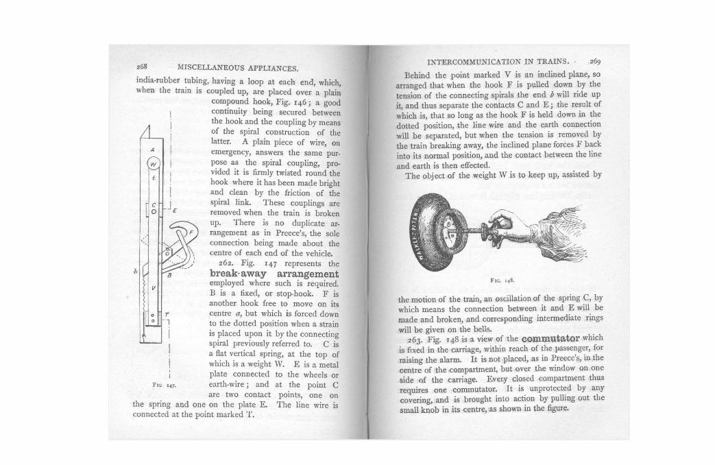
the mot ion of the train, an oscillation of the spring C , b y which means the connect ion be tween it and E will b e made and broken, and corresponding intermediate rings will b e g iven on the bells .
263. F ig . 148 is a v iew o f the commutator which is fixed in the carriage, within reach of the passenger, for raising the alarm. I t is not p laced , as in Preece 's , in the centre o f the compartment , but over the window on one side o f the carriage. E v e r y closed compartment thus requires one commutator . I t is unprotected b y any cover ing , and is brought into action b y pull ing out the small k n o b in its centre, as shown in the figure.
Beh ind the point marked V is an inclined plane, so arranged that when the h o o k F is pul led down b y the tension of the connec t ing spirals the end b will ride up it, and thus separate the contacts C and E ; the result o f which is, that so long as the hook F is held down in the dotted posit ion, the line wire and the earth connect ion will b e separated, but when the tension is removed by the train breaking away, the incl ined plane forces F back into its normal position, and the contact between the line and earth is then effected.
T h e objec t o f the weight W is to k e e p up, assisted b y

F I G . 149 .
van only. I t consists of a bel l and an indicator in the shape of a semaphore signal, wh ich when p laced at danger requires the driver to stop.
266. The question whether the engine signal should be in circuit with the entire train or only worked from the front van has frequently been discussed, and so far the t endency has been to confine it to the latter» but in v iew of the adoption of cont inuous brakes under the control of the engine-driver, it would seem desirable to adopt the former arrangement. A g a i n , it has been thought that an alarm, sounded or signalled to the engine-driver on the electrical apparatus m a y b e sufficiently answered b y sounding the engine-
I N T E R C O M M U N I C A T I O N IN T R A I N S . 271 whistle. I t is open to quest ion i f this course is so desirable as m a y at first sight appear to b e the case. I t is certain that the guard's attention m a y be as, if not more , readily obta ined b y a response o n the bel l placed in his van, as b y the whistle. T h e advantage would therefore appear to b e on the side o f g iv ing the driver the same means of c la iming the attention o f the guard as the guard has o f c la iming that of the driver.
O n withdrawing it from its posit ion o f rest, the line wire is brought into circuit with the earth wire, and the bel ls set ringing. A t the same t ime a small indicator a, F i g . 149 (usually made o f w o o d painted white and red) at tached to a spring b, the tendency o f which is to thrust the disc out at right angles from the line o f carriages, is released. T h e commutator handle cannot b e restored to its place, nor the disc laid alongside the carriage, without the aid of a key, carried b y the guard for that purpose.
264. T h e bell and battery arrangement is similar to that referred to under Preece 's system, except that the bel l is a single-stroke bel l .
265. T h e engine Signal is worked from the front


