
SYSTEMS FOR DAMAGED CAR BODYS …ilot.edu.pl/kones/2011/1_2011/2011_ratajczyk_systems_for...Systems...
6
Journal of KONES Powertrain and Transport, Vol. 18, No. 1 2011 SYSTEMS FOR DAMAGED CAR BODYS MEASUREMENTS Eugeniusz Ratajczyk University of Ecology and Management in Warsaw Wawelska Street 14, 02-061 Warsaw, Poland tel.: +48 601214706 e-mail: [email protected] Abstract Geometrical measurements of car bodies appear mainly in connection with post accident repair processes. They appear also independently in diagnostic measurements. Presentation of measuring systems is very actual in relation to a large number of car accidents. Diagnostic tests of repaired car body and restoring its nominal sizes are essential for safe traffic. The subject area is particularly interesting for service and repairing units e.g. tinsmith’s workshops, but also for car experts. In the article, the methods of car body measurements will be characterized on the example of the use of simple telescopic gauges up to fully computerized electronic measuring systems. The examples of measuring card with basic points, being the nominal points’ coordinates, are presented as well as suggestions concerning the kinds of measuring tips ascribed to those points. Each card with basic points is characteristic only for a particular type of a car body. The examples of illustrations, with visible points on a car body where a prescribed measuring tip should be applied, are also shown. At the end an attempt of measurements’ accuracy estimation will be presented on the example of one of electronic measuring devices. Keywords: measuring systems for car bodies, measuring head for car bodies, electronic gauge for vehicle measuring 1. The principle of car body geometrical measurements The principle of measurements is based on determination of defined points of chassis and car body and comparison of their coordinates with nominal values given by the producer on cards containing basis points. The base points (reference points) are given on CD plates, delivered to users carrying out measurements, and are actualized for new appearing models of car bodies. Fig. 1 shows the example of a card set with base points. Fig. 1. Examples of measuring cards with Basic points on paper and on DC disks
Transcript of SYSTEMS FOR DAMAGED CAR BODYS …ilot.edu.pl/kones/2011/1_2011/2011_ratajczyk_systems_for...Systems...

Journal of KONES Powertrain and Transport, Vol. 18, No. 1 2011
SYSTEMS FOR DAMAGED CAR BODYS MEASUREMENTS
Eugeniusz Ratajczyk
University of Ecology and Management in Warsaw Wawelska Street 14, 02-061 Warsaw, Poland
tel.: +48 601214706 e-mail: [email protected]
Abstract
Geometrical measurements of car bodies appear mainly in connection with post accident repair processes. They
appear also independently in diagnostic measurements. Presentation of measuring systems is very actual in relation to a large number of car accidents.
Diagnostic tests of repaired car body and restoring its nominal sizes are essential for safe traffic. The subject area is particularly interesting for service and repairing units e.g. tinsmith’s workshops, but also for car experts.
In the article, the methods of car body measurements will be characterized on the example of the use of simple telescopic gauges up to fully computerized electronic measuring systems.
The examples of measuring card with basic points, being the nominal points’ coordinates, are presented as well as suggestions concerning the kinds of measuring tips ascribed to those points. Each card with basic points is characteristic only for a particular type of a car body. The examples of illustrations, with visible points on a car body where a prescribed measuring tip should be applied, are also shown.
At the end an attempt of measurements’ accuracy estimation will be presented on the example of one of electronic measuring devices. Keywords: measuring systems for car bodies, measuring head for car bodies, electronic gauge for vehicle measuring 1. The principle of car body geometrical measurements
The principle of measurements is based on determination of defined points of chassis and car
body and comparison of their coordinates with nominal values given by the producer on cards containing basis points. The base points (reference points) are given on CD plates, delivered to users carrying out measurements, and are actualized for new appearing models of car bodies. Fig. 1 shows the example of a card set with base points.
Fig. 1. Examples of measuring cards with Basic points on paper and on DC disks
E. Ratajczyk
The cards contain point numbers with marking their place on a car body. Moreover they contain the information on contact tips enabling their unequivocal placing at a car body point – usually they are in the conic or spherical shape or attachment in a shape of rings or forks. Appropriate software illustrates also the point of mounting of a contact tip. After the measurement, the coordinates of every point are given for comparison with nominal values in order to estimate a dimensional deviation [1,2].
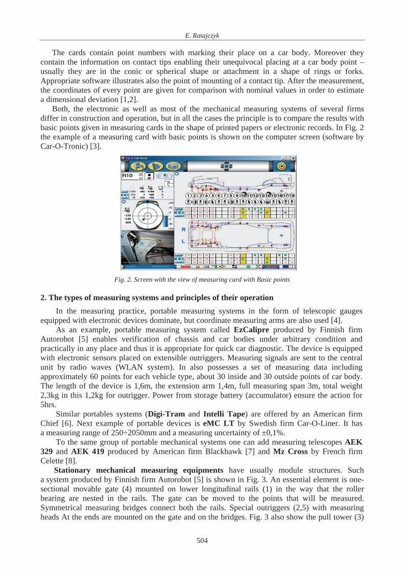
Both, the electronic as well as most of the mechanical measuring systems of several firms differ in construction and operation, but in all the cases the principle is to compare the results with basic points given in measuring cards in the shape of printed papers or electronic records. In Fig. 2 the example of a measuring card with basic points is shown on the computer screen (software by Car-O-Tronic) [3].
Fig. 2. Screen with the view of measuring card with Basic points 2. The types of measuring systems and principles of their operation
In the measuring practice, portable measuring systems in the form of telescopic gauges equipped with electronic devices dominate, but coordinate measuring arms are also used [4].
As an example, portable measuring system called EzCalipre produced by Finnish firm Autorobot [5] enables verification of chassis and car bodies under arbitrary condition and practically in any place and thus it is appropriate for quick car diagnostic. The device is equipped with electronic sensors placed on extensible outriggers. Measuring signals are sent to the central unit by radio waves (WLAN system). In also possesses a set of measuring data including approximately 60 points for each vehicle type, about 30 inside and 30 outside points of car body. The length of the device is 1,6m, the extension arm 1,4m, full measuring span 3m, total weight 2,3kg in this 1,2kg for outrigger. Power from storage battery (accumulator) ensure the action for 5hrs.
Similar portables systems (Digi-Tram and Intelli Tape) are offered by an American firm Chief [6]. Next example of portable devices is eMC LT by Swedish firm Car-O-Liner. It has a measuring range of 250÷2050mm and a measuring uncertainty of ±0,1%.
To the same group of portable mechanical systems one can add measuring telescopes AEK 329 and AEK 419 produced by American firm Blackhawk [7] and Mz Cross by French firm Celette [8].
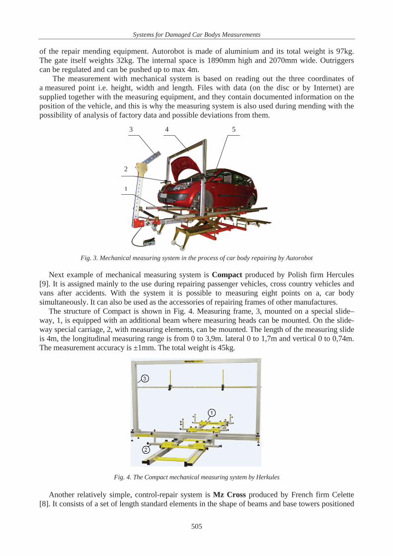
Stationary mechanical measuring equipments have usually module structures. Such a system produced by Finnish firm Autorobot [5] is shown in Fig. 3. An essential element is one-sectional movable gate (4) mounted on lower longitudinal rails (1) in the way that the roller bearing are nested in the rails. The gate can be moved to the points that will be measured. Symmetrical measuring bridges connect both the rails. Special outriggers (2,5) with measuring heads At the ends are mounted on the gate and on the bridges. Fig. 3 also show the pull tower (3)
504
Systems for Damaged Car Bodys Measurements
of the repair mending equipment. Autorobot is made of aluminium and its total weight is 97kg. The gate itself weights 32kg. The internal space is 1890mm high and 2070mm wide. Outriggers can be regulated and can be pushed up to max 4m.
The measurement with mechanical system is based on reading out the three coordinates of a measured point i.e. height, width and length. Files with data (on the disc or by Internet) are supplied together with the measuring equipment, and they contain documented information on the position of the vehicle, and this is why the measuring system is also used during mending with the possibility of analysis of factory data and possible deviations from them.
1
2
3 4 5
Fig. 3. Mechanical measuring system in the process of car body repairing by Autorobot Next example of mechanical measuring system is Compact produced by Polish firm Hercules
[9]. It is assigned mainly to the use during repairing passenger vehicles, cross country vehicles and vans after accidents. With the system it is possible to measuring eight points on a, car body simultaneously. It can also be used as the accessories of repairing frames of other manufactures.
The structure of Compact is shown in Fig. 4. Measuring frame, 3, mounted on a special slide–way, 1, is equipped with an additional beam where measuring heads can be mounted. On the slide-way special carriage, 2, with measuring elements, can be mounted. The length of the measuring slide is 4m, the longitudinal measuring range is from 0 to 3,9m. lateral 0 to 1,7m and vertical 0 to 0,74m. The measurement accuracy is ±1mm. The total weight is 45kg.
Fig. 4. The Compact mechanical measuring system by Herkules Another relatively simple, control-repair system is Mz Cross produced by French firm Celette
[8]. It consists of a set of length standard elements in the shape of beams and base towers positioned
505
E. Ratajczyk
on a frame called Sevenne. The basic equipment consists of 22 towers and 5 beams. The kit of Mz systems contains moreover reach set of standard elements appropriate for each car model.
Swedish firm Car-O-Liner [3] offers mechanical measuring systems called Car-O-Mech and Car-O-Mech Vision. Car-O-Mech consists of several measuring sets (measuring bridge, sliders, number of linear and angular adaptors and set of tip[s ends). Car-O-Liner Vision is equipped with electronic terminal PDA enabling to make records with measurement results and data actualization through Internet.
Electronic measuring systems are produced by several manufactures. As the best known on our market one should mention: Autorobot (Finland OY) [5] represented in Poland by Jan Soba ski Auto System, Chief Automotive Technologies (USA) [6] - in Poland Armal Sp.z o.o., Spanesi (Italy) – in Poland Iteltecnica with logo Spanesi Polska [10], Herkules Auto-Technika Warsztatowa (Poland) [9], Celette (France) [8] – represented in Poland by Masz s.c, Car-O-Liner (Sweden) [3] – in Poland C.T.S. Sp. z o.o. and Blackhawk S.A (USA) – in Poland by NTS sp. z o.o. [7].
In principle of the most of electronic measuring systems consists in bringing the measuring tip into a contact with base points of a car body in order to estimate their coordinates x,y,z. Measuring head moves along the beam equipped with measuring systems mounted along the investigated car body. In some devices measuring head mounted on the outrigger, and a measuring system is placed in a separated box situated beyond the car body. Signal from measuring head is wirelessly sent to the computer. Then the results are processed in order to compare the investigated base point coordinates with nominal coordinates and to establish on eventual deviation from a nominal dimension.
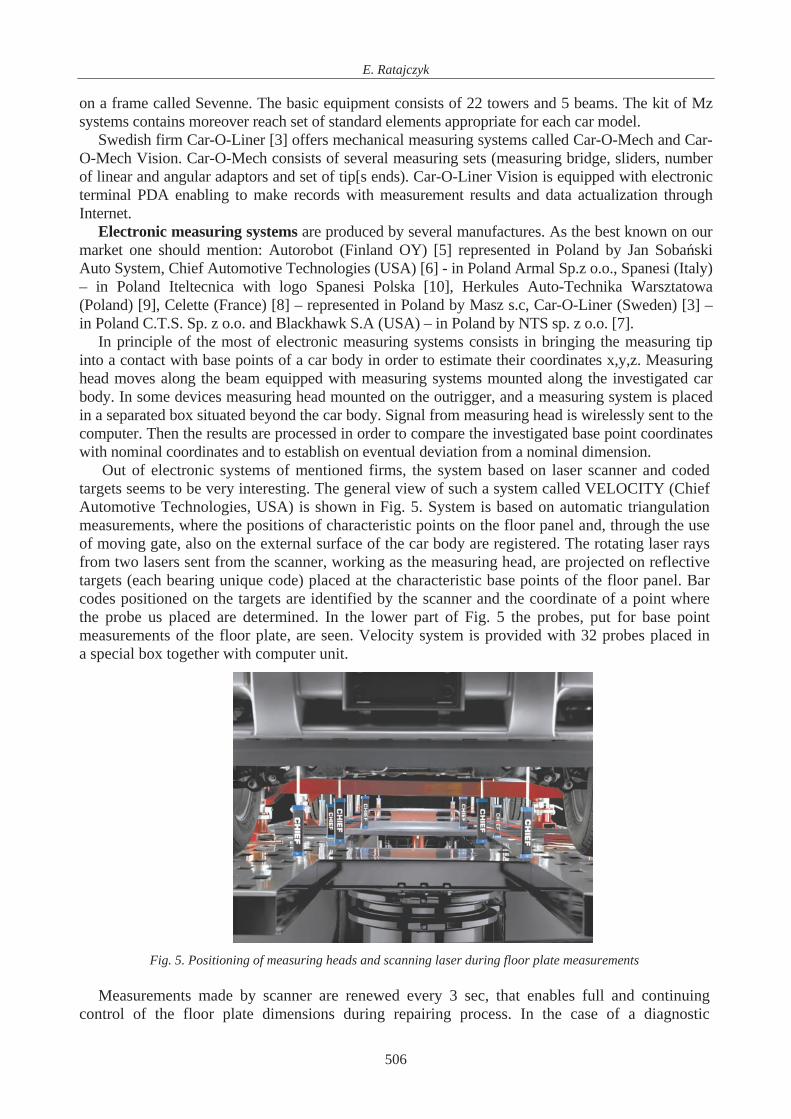
Out of electronic systems of mentioned firms, the system based on laser scanner and coded targets seems to be very interesting. The general view of such a system called VELOCITY (Chief Automotive Technologies, USA) is shown in Fig. 5. System is based on automatic triangulation measurements, where the positions of characteristic points on the floor panel and, through the use of moving gate, also on the external surface of the car body are registered. The rotating laser rays from two lasers sent from the scanner, working as the measuring head, are projected on reflective targets (each bearing unique code) placed at the characteristic base points of the floor panel. Bar codes positioned on the targets are identified by the scanner and the coordinate of a point where the probe us placed are determined. In the lower part of Fig. 5 the probes, put for base point measurements of the floor plate, are seen. Velocity system is provided with 32 probes placed in a special box together with computer unit.
Fig. 5. Positioning of measuring heads and scanning laser during floor plate measurements
Measurements made by scanner are renewed every 3 sec, that enables full and continuing control of the floor plate dimensions during repairing process. In the case of a diagnostic
506

Systems for Damaged Car Bodys Measurements
assessment i.e. without repairing the process can be finished with printing the report on the geometrical state of the car.
The mentioned above measuring systems my b used as diagnostic system but in most of the cases they operate in connection with repair devices.
There appeared also repair equipment mounted directly on the floor of the repair shop. The repair towers are connected by means of pulls to U-iron sections assembled immovable to the floor.
3. Attempt of measurement accuracy estimation
The univocal judgment of the measurement accuracy is rather difficult. Roughly the accuracy
of the base points estimation lies in the range from ±0,2mm to ±2mm. Several attempts have bee undertaken to judge the measurement accuracy of care bodies with
different degree of damage using selected measuring systems. We present here shortly the experimental attempt of measurement accuracy estimation for damaged car body of Passat B6 with the use of electronic system NAJA produced by Celette (Fig.6).
Fig. 6. The NAJA measuring system and an example of using
The system make sit possible to measure car bodies, floor plates and door posts. The devise consists of a measuring rail with a head with rotary arm moving on it. At the end of the arm there is a contact tip that can be put into a measured point of car body. Measuring head sends the signal by radio, with the maximum range of 15m, to the computer.
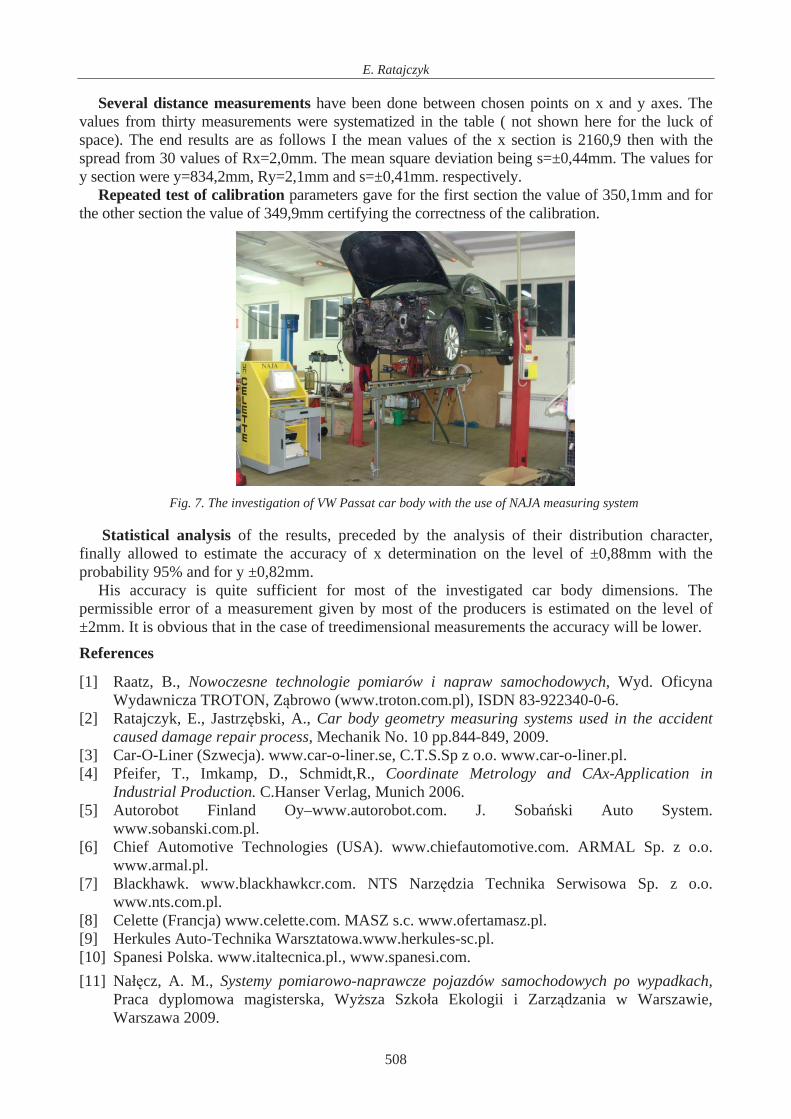
Experiments performed by Na cz [11] concerned measurements of damaged VW passed B6 car body Fig.7).
eTh procedure consisted of following steps: 1. Checking (verification) of calibration parameters of the system.
base. 2. The choice of the measuring sheet with measuring points from the datameasured. 3. The choice of the definite points on the car body to be
4. Repeated test of calibration parameters of the system. 5. The determination of point values and the statistical valuation of the accuracy. The test of calibration parameters has been performed on the length master with reference
distances between three measuring points giving two lengths. For one of the sections of the standard length being 350,05±0,2mm, the values 350,0mm has been obtained for the other of 349,95±0,2mm the values 349,9 was obtained.
The choice of measuring points from data base was limited to points on the floor panel. For accuracy estimation the point 40 and 58 also 57 and 58 were chosen and appropriate contact tips were selected.
507
E. Ratajczyk
Several distance measurements have been done between chosen points on x and y axes. The values from thirty measurements were systematized in the table ( not shown here for the luck of space). The end results are as follows I the mean values of the x section is 2160,9 then with the sp
epeated test of calibr e of 350,1mm and for the other sec ration.
read from 30 values of Rx=2,0mm. The mean square deviation being s=±0,44mm. The values for y section were y=834,2mm, Ry=2,1mm and s=±0,41mm. respectively.
R ation parameters gave for the first section the valution the value of 349,9mm certifying the correctness of the calib
, preceded by the analysis of their distribution character, fin
ermissible error of a measurement given by most of the producers is estimated on the level of
bvious that in the case of treedimensional measurements the accuracy will be lower.
2340-0-6. he accident
[3] o.o. www.car-o-liner.pl.
.Hanser Verlag, Munich 2006.
om.pl.
Serwisowa Sp. z o.o.
rtamasz.pl.
[10]
Fig. 7. The investigation of VW Passat car body with the use of NAJA measuring system
Statistical analysis of the resultsally allowed to estimate the accuracy of x determination on the level of ±0,88mm with the
probability 95% and for y ±0,82mm. His accuracy is quite sufficient for most of the investigated car body dimensions. The
p±2mm. It is o References
[1] Raatz, B., Nowoczesne technologie pomiarów i napraw samochodowych, Wyd. Oficyna Wydawnicza TROTON, Z browo (www.troton.com.pl), ISDN 83-92
[2] Ratajczyk, E., Jastrz bski, A., Car body geometry measuring systems used in tcaused damage repair process, Mechanik No. 10 pp.844-849, 2009. Car-O-Liner (Szwecja). www.car-o-liner.se, C.T.S.Sp z
[4] Pfeifer, T., Imkamp, D., Schmidt,R., Coordinate Metrology and CAx-Application in Industrial Production. C
[5] Autorobot Finland Oy–www.autorobot.com. J. Soba ski Auto System. www.sobanski.c
[6] Chief Automotive Technologies (USA). www.chiefautomotive.com. ARMAL Sp. z o.o. www.armal.pl.
[7] Blackhawk. www.blackhawkcr.com. NTS Narz dzia Technika www.nts.com.pl.
[8] Celette (Francja) www.celette.com. MASZ s.c. www.ofe[9] Herkules Auto-Technika Warsztatowa.www.herkules-sc.pl.
Spanesi Polska. www.italtecnica.pl., www.spanesi.com. [11] Na cz, A. M., Systemy pomiarowo-naprawcze pojazdów samochodowych po wypadkach,
Praca dyplomowa magisterska, Wy sza Szko a Ekologii i Zarz dzania w Warszawie, Warszawa 2009.
508


![Japanische bodys [ Adult only ]](https://static.fdocuments.net/doc/165x107/58cf76261a28abe6688b5d85/japanische-bodys-adult-only-.jpg)