Systemf o distribution in diverse equipment Electrical 10padotec.com/pdf/brouchure.pdf ·...
54
Electrical fittings 10 Components for low-voltage distribution systems and medium-voltage insulators
Transcript of Systemf o distribution in diverse equipment Electrical 10padotec.com/pdf/brouchure.pdf ·...

Electricalfittings 10
Components for low-voltage distribution systems and medium-voltage insulators
June 2009
Dealer and technical service for Spain:
Francesc Samaranch, 11, Nave D - 08750 MOLINS DE REI (Barcelona) - SpainPhone +34 93 680 15 64 - Fax +34 93 680 04 39 - E-mail: [email protected] / [email protected] de Navacerrada, 16 - 28850 TORREJÓN DE ARDOZ (Madrid) - SpainPhone +34 91 676 21 89 - Fax +34 91 656 31 79 - E-mail: [email protected]
•Photographiesgentilityofthecompanies: T.S.K. of Gijón EMTE, S.A.
Distribution center in Aceralia
Systemofdistribution ofbusbarsinstalled indiverseequipment
Control center of motors in Aceralia
Control center of motors in Aceralia
Distribution center Barranco of Tirajana-Felguera
One of the installled equipment of distribution in the Liceo of Barcelona
Detail transformation center Barranco of Tirajana-Felguera
Constructive detail with the systems “PARALEL 170” and “EQUILATER 170”
ForGermany: JITEX Elektrovertrieb G.m.b.H. Gewerbepark Wagnerbruch, 4 42279 WuppertalFor France: FLOBEX FRANCE, 15, Chemin de la Montée Girard 42420 LORETTEFor Chile: NDU Ingeniería Ltda. Santa Elisa 498 - La Cisterna - SantiagoFor Sweden: BEVING ELEKTRONIK, Jägerhorns Väg 8 14175 Rungens KurvaForItaly: ITALWEBER, Via Risorgimento 84, 20017 RHO, MilanoFor Israel: KATZENSTEIN ADLER, 4 Haomanut St. industrial Park Kiryat Nordau, P.O.Box 6145 NETANYA 42504ForPortugal: Next incorporationn

Ove
rvie
w
Has been manufacturing electrical fittings since 1986 addressed to solve the complex problems involved in the electrical system assembly to afford faster setup and substantial cost savings.
PADO fittings made for optimally efficient design work by technical departments and engineering teams. Dielectric and mechanical characteristics under shortcircuit conditions comply with VDE 0660 part 500 standards (points 8, 2, 3, 2, 3, 6, 11/1984 edition), as certified by tests performed at national and European laboratories.
Pàmies-Domínguez, S.L.June 2009

135
M-6105
50
25
40
15M-5
26
26
30
18
40
6
M69950
19
16
DIN Rail35 mm
46DIN Rail35 mm
14 16
40
1827
6
161414
40
6
M69950
19
16
DIN Rail35 mm
46DIN Rail35 mm
14 16
4018
276
161414
Ø D
C
HA/F

6,5
15
26 (41)
2
5
22 (32)
102
41 (38)
32
152
16 (20)
6,5
102
5
16 (20)
Inde
x
Pages 5 - 12
Pages 29 - 38
Pages 13 - 28
PADO SYSTEM
•Insulatorsupports
•Through&blindinsulators
•Technicalfeatures
•CompletedistributionunitkitsKMIIIorIII+N•DistributorscomponentsKM•Four-poledistributionunits•Smalldistributionunits•Distributionunitsforphotovoltaicenergy
•Newmodularsupport•Insulators•Insulatorsupports•Medium-voltageinsulators•Technicalinformation
•Short-circuitcurrentinlow-voltage three-phasesystems
•Alphanumericindex
ASSEMBLYANDWIRINGSOLUTIONS•Accessories•WOFIXsystem•Spacers•Specialnutsandbolts•Toolsfordrillingflexiblebars
40
6
M69950
19
16
DIN Rail35 mm
46DIN Rail35 mm
14 16
40
1827
6
161414
Ø D
C
HA/F
Pages 37 - 47
10
Page 48
Pages 49 - 52

Pages 6 - 9 Pages 10 - 11
Pages 16 - 20
Pages 21 - 22
Page 23
Pages 14 - 15
NEW
Pages 24 - 25
Page 26
Page 27
Pages 30 - 33
Page 34 NEW
Page 36Page 38
Page 40
Page 41
Page 44
Page 47
Page 42
5
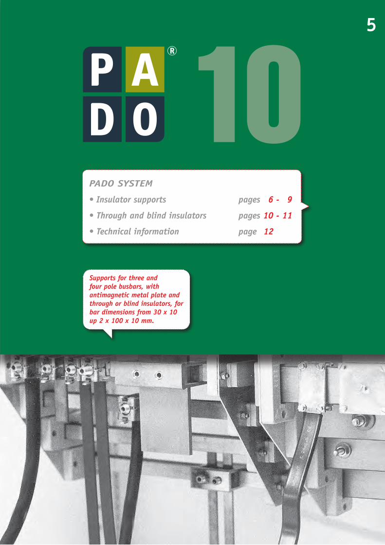
PADO SYSTEM
•Insulatorsupports pages 6 - 9
•Throughandblindinsulators pages10 - 11
•Technicalinformation page12
Supportsforthreeandfourpolebusbars,withantimagneticmetalplateandthroughorblindinsulators,forbardimensionsfrom30x10up2x100x10mm.
10
6
10
6230
10
6186
46PerfilDIN35 mm
14 1640
1827
616
1414
40
6
M69950
19
16
35
32
230
32
35190
35
32
320
Perfil DIN35 mm
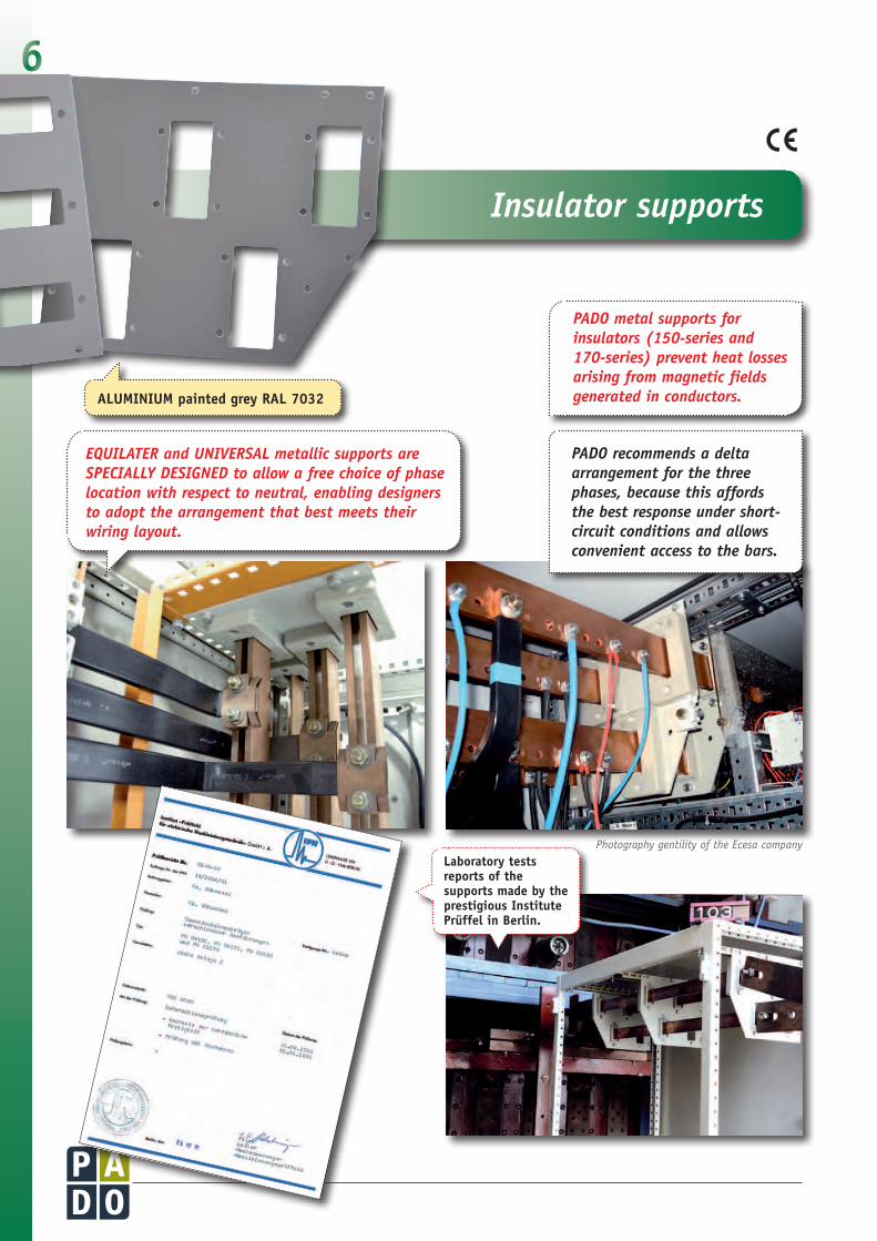
Insulatorsupports
PADOmetalsupportsforinsulators(150-seriesand170-series)preventheatlossesarisingfrommagneticfieldsgeneratedinconductors.ALUMINIUM painted grey RAL 7032
EQUILATERandUNIVERSALmetallicsupportsareSPECIALLYDESIGNEDtoallowafreechoiceofphaselocationwithrespecttoneutral,enablingdesignerstoadoptthearrangementthatbestmeetstheirwiringlayout.
PADOrecommendsadeltaarrangementforthethreephases,becausethisaffordsthebestresponseundershort-circuitconditionsandallowsconvenientaccesstothebars.
Laboratory tests reports of the supports made by the prestigious Institute Prüffel in Berlin.
Photography gentility of the Ecesa company

7Insulatorsupports
Three and four poles, busbars up to 2000A, thickness of 4mm.
EQUILATER150 PM04150
Three and four poles, busbars up to 3100A, thickness of 4mm.
EQUILATER170 PM04170
Three phases plus neutral busbars up to 5400A.Up to four 100 x 10 bars per phase and four 100 x 10 bars for neutral, 5mm thick.
EQUILATER170double PM08170
Three poles, busbars up to 2000A, 4mm thick.
PARALEL150 PM03150
Four poles, busbars up to 3100A, 4mm thick.
PARALEL170 PM03170
UNIVERSAL150 PM01000
Three or four poles, busbars up to 2000A, thickness of 4mm.
UNIVERSAL170 PM02000
Three and four poles, busbars up to 3100A, thickness of 4mm.
Three phases, busbars up to 5400A.Up to four 100 x 10 bars per phase, 5mm thick.
EQUILATER170double PM06170
Three poles busbars up to 2000A, 4mm thick.
PARALEL150 PM03153
Three poles, busbars up to 3100A, 4mm thick.
PARALEL170 PM03130

8
PM01003-R PM01004-LPM01005-R PM01006-L
Special plates for fitting three or four-pole busbars at the inputs of large power distribution systems, for convenient input and output wiring. These plates take flat bars up to 2 x 100 mm, or H-section or double H-section bar carrying currents up to 3200A, for wiring with cables or flexible bars. The step configuration ensures unobstructed visibility for all connections.
Insulatorsupports
Specialsupports
Special for input and output busbars up to 2000A. Double profile, left or right.
Right PM01003-RLeft PM01004-L
Special for lower busbars up to 2000A
Right PM01005-RLeft PM01006-L
Aluminium 4 mm thick. For flat bars up to 2x60x10 Aluminium 3 mm thick. For flat bars up to 2x60x10
Three poles busbars up to 2000A
Aluminium 4mm.
TRIANGULAR150 PM04153
PM04173 PM04173/B
Three polesbusbars up to 3100A PM04173 - PM04173/B
Aluminium 4mm.
METRO150
ESCALERA150,3poles ESCALERA150,4poles
PM00150 PM00170
Bar up to 2000A PM00150Bar up to 3100A PM00170
Aluminium 4mm.
OF1POLE
Three poles plus neutral busbars up to 3100A, thickness of 4mm.
PARALEL150/170 PM03161
9
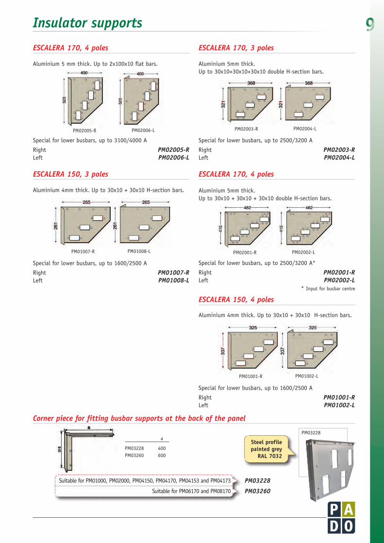
* Input for busbar centre
PM02005-R PM02006-L
PM01007-R PM01008-L
PM02003-R PM02004-L
PM02001-R PM02002-L
Special for lower busbars, up to 3100/4000 A
Right PM02005-RLeft PM02006-L
Special for lower busbars, up to 2500/3200 A
Right PM02003-RLeft PM02004-L
Special for lower busbars, up to 2500/3200 A*
Right PM02001-RLeft PM02002-L
Special for lower busbars, up to 1600/2500 A
Right PM01007-RLeft PM01008-L
Aluminium 5 mm thick. Up to 2x100x10 flat bars. Aluminium 5mm thick. Up to 30x10+30x10+30x10 double H-section bars.
Aluminium 5mm thick. Up to 30x10 + 30x10 + 30x10 double H-section bars.
Aluminium 4mm thick. Up to 30x10 + 30x10 H-section bars.
PM01001-R PM01002-L
Special for lower busbars, up to 1600/2500 A
Right PM01001-RLeft PM01002-L
Aluminium 4mm thick. Up to 30x10 + 30x10 H-section bars.
Insulatorsupports
ESCALERA170,4poles
ESCALERA150,3poles
ESCALERA170,3poles
ESCALERA170,4poles
ESCALERA150,4poles
a
PM03228 400PM03260 600
Steel profile painted grey
RAL 7032
PM03228
Cornerpieceforfittingbusbarsupportsatthebackofthepanel
PM03228
PM03260
Suitable for PM01000, PM02000, PM04150, PM04170, PM04153 and PM04173
Suitable for PM06170 and PM08170

10
10
6230
10
6186
46PerfilDIN35 mm
14 1640
1827
616
1414
40
6
M69950
19
16
35
32
230
32
35190
35
32
320
Perfil DIN35 mm
Through&blindinsulators
•Thesethroughandblindinsulatorsfeatureasimpleone-piecedesign.Insulatorsaresizedforeachinsulatorsupport,withnoneedforadjustment.
•Nodrillingbarsrequired.
Halogenfree fibreglassreinforced polyester.
Barsnumber Partition
Through Blind Compatiblemetalplate Widemmxthickmm Reference Reference (numberofpoles)
1 of 40x5 + 1 of 50x5 + 1 of 60x5 Yes AP04565* AC04565* 1 of 30x10 – AP03010 AC03010 1 of 40x10 – AP04010 AC04010 1 of 50x10 – AP05010 AC05010 1 of 50x12 – AP05012 AC05012 1 of 60x10 – AP06010 AC06010 2 of 30x10 Yes AP23010* AC23010* 2 of 40x10 Yes AP24010* AC24010* 2 of 50x10 Yes AP25010* AC25010* 2 of 60x10 Yes AP26010* AC26010* 2 of 50x10 No AP05020 AC05020 2 of 50x12 No AP05024 AC05024 2 of 60x10 No AP06020 AC06020
1 bar H 30x10 – AP23210 AC23210
PM01007R/PM01008l (3) PM01001R/PM01002l (4)
PM01000 (3 or 4)
PM04150 (3 or 4)
PM03153 (3), PM03150 (4)
PM04153 (3)
PM00150 (1)
PM01003R/PM01004L (3)
PM01005R/PM01006L (4)
* These insulators must not be used for a single bar, the partition could break under shortcircuit conditions.
* These insulators must not be used for a single bar, the partition could break under shortcircuit conditions.
•TheyarefittedontotheantimagneticmetallicsupportbymeansoftwoM8x20bolts.
Barsnumber Partition
Through Blind Compatiblemetalplate Widemmxthickmm Reference Reference (numberofpoles)
1 of 80x10 – AP18010 AC18010
1 of 100x10 – AP11001 AC11001
2 of 80x10 Yes AP28010* AC28010*
2 of 100x10 Yes AP21001* AC21001*
3 of 80x5 Yes AP03805* AC03805*
3 of 100x5 Yes AP31005* AC31005*
1 bar HH 30x10 – AP33310 AC33310
PM02003R/PM02004l (3) PM02001R/PM02002l (4)
PM02000 (3 or 4)PM04170 (3 or 4)PM06170 (2 x 3), PM08170 (2 x 4)PM03130 (3), PM03170 (4)PM03161 (3 + N)PM04153 (3), PM04173 (4)PM00170 (1)PM02005R/PM02006L (4)
150-SeriesforflatbarsandH-sectionbars(from30x10to60x10)
170-SeriesforflatbarsandHH-sectionbars(from80x10to100x10)

11
12 Units
15 Units
AP18010AC18010
AP11001AC11001
AP28010AC28010
AP21001AC21001
AP38005AC38005
AP31005AC31005
AP33310AC33310
AP23010AC23010AP24010AC24010AP25010AC25010AP26010AC26010
AP28010AC28010AP21001AC21001
AP33310AC33310
AP03805AC03805AP31005AC31005
AP23210AC23210
Through&blindinsulators
AP04565AC04565
AP03010AC03010AP04010AC04010
AP05010AC05010AP05012AC05012
AP06010AC06010
AP23010AC23010AP24010AC24010AP25010AC25010AP26010AC26010
AP05020AC05020AP05020AC05024AP06020AC06020
AP23210AC23210
SERIE150
SERIE170
Included(x complete package)
Included(x complete package)

12 TechnicalfeaturesPADOSYSTEM
The Paralel, Equilater and Universal (patent nº MU 8703830) ranges of busbar components from PADO derive from exten-sive experience in design and construction of low-voltage distribution systems. All products meet Spanish standards on low-voltage power distribution (three-phase plus neu-tral), and comply with new low-voltage regulations, ITC-BT-19,2.2.2, which specify that neutral conductors must have the same crosssection as phase conductors.
As well as affording dielectric strength consistent with the voltages applied, busbar supports must also withstand the mechanical stresses arising from phase-
“UNIVERSAL”
PM01000 - PM02000
“PARALEL150”
PM03150
“PARALEL170”
PM03170
PM04150 - PM04170
L = 400 mm L = 500 mm L = 600 mm
mm Painted Brilliant I”k Is I”k Is I”K Is N.ºxAxG Amp. Amp. KA KA KA KA KA KA
40 x 10 850 760 60 126 55 115 50 105
50 x 10 1030 920 60 126 55 115 50 105
60 x 10 1200 1060 60 126 55 115 50 105
2x50x10 1800 1600 80 176 75 165 70 154
2x60x10 2100 1900 80 176 75 165 70 154
80 x 10 1560 1380 80 176 75 165 70 154
100 x 10 1880 1700 80 176 75 165 70 154
2x80x10 2500 2300 85 187 80 176 75 165
2x100x10 3100 2800 85 187 80 176 75 165
40 x 10 850 760 50 110 45 100 40 88
50 x 10 1030 920 50 110 45 100 40 88
60 x 10 1200 1060 50 110 45 100 40 88
2x50x10 1800 1600 70 147 65 137 60 126
2x60x10 2100 1900 70 147 65 137 60 127
80 x 10 1560 1380 60 126 55 115 50 105
100 x 10 1880 1700 60 126 55 115 50 105
2x80x10 2500 2300 70 147 65 137 60 126
2x100x10 3100 2800 70 147 65 137 60 126
Measuresrectangularcopperbarpermissibleintensity
‘EQUILATER”
•Dielectricstrength:19Kv/mm.•Leakagecurrenttest:Kc600.•Flametest:VO/UL94-Self-extinguishingto
UNE53.315-86.•Maximumtemperature:Above220°C.•Colour:greyRAL7032.
to-phase or phase-to-earth short-circuits. Systems are designed on the basis of symmetrical short-circuit current (dynamic) Is, in accordance with VDE 0660, part 500, point 8.2.3.2.3.b (edition 11/1984)
Short-circuit handling capability depends on the busbar layout, cross-section, and support spacing. The closer the supports, the greater the mechanical strength in with-standing the dynamic effects of short-circuit conditions. The table bellow shows short-circuit current-handling capability for different copper cross-sections, layouts and support spacing.
Maximumcurrentratingandshort-circuit handlingcapacitiesforcopperbarsofdifferent dimensionswithdifferentsupportspacings(L)
1013
•Newmodularsupport pages 14 - 15
•Insulatingsupports foruniversalapplication pages 16 - 20
•Stepinsulatingsupports pages21 - 22
•BlockandCombiinsulatingsupports page23
•Hexagonalinsulators pages24 - 25
•Medium-voltageinsulators pages26 - 27
•Technicalinformation page28
14
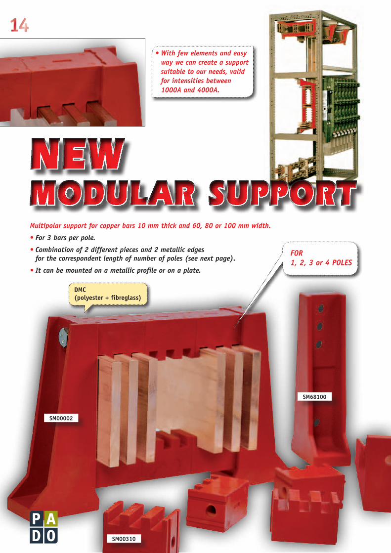
NEWMODULAR SUPPORTMultipolarsupportforcopperbars10mmthickand60,80or100mmwidth.
•For3barsperpole.
•Combinationof2differentpiecesand2metallicedgesforthecorrespondentlengthofnumberofpoles(seenextpage).
•Itcanbemountedonametallicprofileoronaplate.
•Withfewelementsandeasywaywecancreateasupportsuitabletoourneeds,validforintensitiesbetween1000Aand4000A.
SM00002
SM00310
SM68100
DMC (polyester + fibreglass)
FOR 1,2,3or4POLES

15
10
6230
10
6186
46PerfilDIN35 mm
14 1640
1827
616
1414
40
6
M69950
19
16
35
32
230
32
35190
35
32
320
Perfil DIN35 mm
Newmodularsupport
+ L
M10L: 475 mm.
+ L
M10L: 355 mm.
+ L
M10L: 235 mm.
+ L
M10L: 115 mm.
Threaded rods, nuts and washers: galvanized and achromatized steel (CR3)
4Poles
SM00004
Intensityvalues
3Poles
SM00003
2Poles
SM00002
1Pole
SM00001
SM68100 SM00310
Width Thickness Intensity
60 mm. 10 mm. 2800 A
80 mm. 10 mm. 3300 A
100 mm. 10 mm. 4000 A
DMC: (polyester + fibreglass) selfextinguishing, halogenfree.
60
40
180
75
Hole for 100 mm bars
Hole for 80 mm bars
Hole for 60 mm bars
16
10
6230
10
6186
46PerfilDIN35 mm
14 1640
1827
616
1414
40
6
M69950
19
16
35
32
230
32
35190
35
32
320
Perfil DIN35 mm
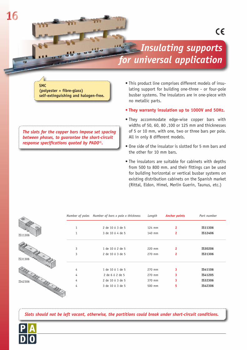
SMC (polyester + fibreglass) selfextinguishing and halogenfree.
Theslotsforthecopperbarsimposesetspacingbetweenphases,toguaranteetheshort-circuitresponsespecificationsquotedbyPADO®.
• This product line comprises different models of insu-lating support for building one-three - or four-pole busbar systems. The insulators are in one-piece with no metallic parts.
• They warranty insulation up to 1000V and 50Hz.
• They accommodate edge-wise copper bars with widths of 50, 60, 80 ,100 or 125 mm and thicknesses of 5 or 10 mm, with one, two or three bars per pole. All in only 8 different models.
• One side of the insulator is slotted for 5 mm bars and the other for 10 mm bars.
• The insulators are suitable for cabinets with depths from 500 to 800 mm. and their fittings can be used for building horizontal or vertical busbar systems on existing distribution cabinets on the Spanish market (Rittal, Eldon, Himel, Merlin Guerin, Taunus, etc.)
Slotsshouldnotbeleftvacant,otherwise,thepartitionscouldbreakundershort-circuitconditions.
Numberofpoles Numberofbarsxpolexthickness Length Anchorpoints Partnumber
1 2 de 10 ó 3 de 5 124 mm 2 IS11306
1 3 de 10 ó 4 de 5 140 mm 2 IS12406
3 1 de 10 ó 2 de 5 220 mm 2 IS30206
3 2 de 10 ó 3 de 5 270 mm 2 IS31306
4 1 de 10 ó 1 de 5 270 mm 3 IS41106
4 2 de 6 ó 2 de 5 270 mm 3 IS41205
4 2 de 10 ó 3 de 5 370 mm 3 IS32306
4 3 de 10 ó 3 de 5 500 mm 5 IS42306
IS11306
IS31306
IS42306
Insulatingsupports foruniversalapplication
17
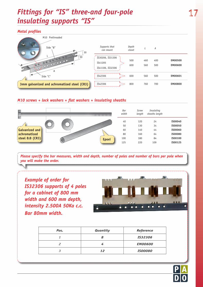
IS30206, IS31306 500 460 400 EM00500
IS41205
IS41106, IS32306 600 560 500 EM00600
IS42306 600 560 500 EM00601
IS42306 800 760 700 EM00800
Supportsthat canmount
Depth closet L A
40 120 24 IS00040
50 130 34 IS00050
60 140 44 IS00060
80 160 64 IS00080
100 180 84 IS00100
125 220 109 IS00125
Bar width
Screw length
Insulatingsheathslength
Fittingsfor“IS”three-andfour-pole insulatingsupports“IS”
3mm galvanized and achromatized steel (CR3)
Galvanized and achromatized steel 8:8 (CR3) Epoxi
ExampleoforderforIS32306supportsof4polesforacabinetof800mmwidthand600mmdepth,intensity2.500A50Kac.c.Bar80mmwidth.
Metalprofiles
M10screws+lockwashers+flatwashers+insulatingsheaths
Pos. Quantity Reference
1 8 IS32306
2 4 EM00600
3 12 IS00080
Pleasespecifythebarmeasures,widthanddepth,numberofpolesandnumberofbarsperpolewhenyouwillmaketheorder.
Side "B"
M10 Prethreaded
L
A
30
30
Side "C"

18Short-circuit response specifications for three-and four-pole vertical copper bar supports at fixed pole spacing.
Technicalinformation
•Material:SMC•Workingtemperature:upto165ºC
cc (min): Spacing between centres of adjacent phases.
- Spacing calculated on basis of set safety factor. Wider spacing is required at lower safety factors.
- Assuming tough fasteners (hardness 8:8).
IS30206
5 x 2 - 3 poles 75
930 475 —
10 x 1 - 3 poles 1000 1000 850
IS31306
5 x 3 - 3 poles 100
1000 520 —
10 x 2 - 3 poles 1000 1000 400
IS41205
5 x 2 - 4 poles 80
860 440 —
6 x 2 - 4 poles 1000 530 —
IS41106 5 x 1 - 4 poles
80 1000 — —
10 x 1 - 4 poles 1000 875 —
IS32306 5 x 3 - 4 poles
105 1000 725 300
10 x 2 - 4 poles 1000 900 420
IS42306 5 x 3 - 4 poles
115 1000 800 300
10 x 3 - 4 poles 1000 1000 480
ProductCode
c-cfixed between-centres
spacingmm
Maximumratedcurrentforcopperplateandshort-circuitcurrentfordifferentsupportspacing
25kA1seg. 35kA1seg. 50kA1seg.
L L L
Barthickness mmxnumber ofbarsxpole
For50mmwidthbars
Maximumratedcurrentforcopperplateandshort-circuitcurrentfordifferentsupportspacing
25kA1sec. 35kA1sec. 50kA1sec.
L L L
IS30206
5 x 2 - 3 poles 75
780 400 200
10 x 1 - 3 poles 1000 1000 1000
IS31306
5 x 3 - 3 poles 100
860 440 210
10 x 2 - 3 poles 1000 870 430
IS41205
5 x 2 - 4 poles 80
350 200 —
6 x 2 - 4 poles 220 — —
IS41106 5 x 1 - 4 poles
80 980 460 230
10 x 1 - 4 poles 880 450 220
IS32306 5 x 3 - 4 poles
105 850 410 250
10 x 2 - 4 poles 890 440 260
IS42306 5 x 3 - 4 poles
115 730 360 210
10 x 3 - 4 poles 1000 500 300
ProductCode
c-cfixed between-centres
spacingmm
Barthickness mmxnumber ofbarsxpole
For100mmwidthbars

19Dimensionsofone-phaseinsulatingsupports
Dimensionsofthree-phaseinsulatingsupports
IS11306
IS30206
IS31306
IS12406
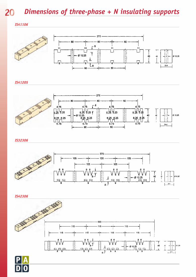
20 Dimensionsofthree-phase+Ninsulatingsupports
IS41106
IS41205
IS42306
IS32306
21
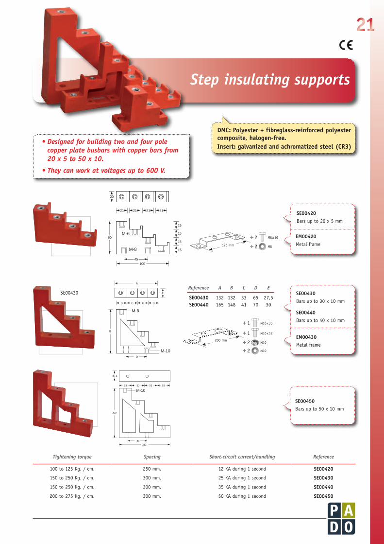
SE00420Bars up to 20 x 5 mm
EM00420Metal frame
SE00450Bars up to 50 x 10 mm
SE00430Bars up to 30 x 10 mm
SE00440Bars up to 40 x 10 mm
EM00430Metal frame
Reference A B C D E
SE00430 132 132 33 65 27,5SE00440 165 148 41 70 30
21 21 21 21
60M-6
M-8
45100
20
15
15
15
15
A
C
E
C C C
D
B
M-8
M-10
80
200
M-1053 53 53 53
212
35,4
SE00430
Tighteningtorque Spacing Short-circuitcurrent/handling Reference
100 to 125 Kg. / cm. 250 mm. 12 KA during 1 second SE00420
150 to 250 Kg. / cm. 300 mm. 25 KA during 1 second SE00430
150 to 250 Kg. / cm. 300 mm. 35 KA during 1 second SE00440
200 to 275 Kg. / cm. 300 mm. 50 KA during 1 second SE00450
10
6230
10
6186
46PerfilDIN35 mm
14 1640
1827
616
1414
40
6
M69950
19
16
35
32
230
32
35190
35
32
320
Perfil DIN35 mm
DMC: Polyester + fibreglassreinforced polyester composite, halogenfree.Insert: galvanized and achromatized steel (CR3)
Stepinsulatingsupports
•Designedforbuildingtwoandfourpolecopperplatebusbarswithcopperbarsfrom20x5to50x10.
•Theycanworkatvoltagesupto600V.
125 mm
+2+2
M8 x 10
M8
+1+1
+2+2
M10 x 35
M10 x 12
M10
M10200 mm

22
Reference A B C D E F G H
SE00215 54 40,5 20 12 15 48 20 15SE00225 80 62,5 30 15 25 60 27 19
SE00225
4polesupport,forfittingprotectivecover
Stepinsulatingsupports
SE00215Bars up to 15 x 5 mm
SE00225Bars up to 25 x 5 mm
AB
C
DEED
M-6
F
G
H
SE00525Bars up to 25 x 5 mm
135
M-6
105
50
25
40
15
M-5
26
26
30
18
Short-circuit response specifications for two-to four-pole step-configuration horizontal copper bar supports at fixed pole spacing.
Technicalinformation
•Material:DMC•Workingtemperature:Upto165ºC
SE00215 15 x 3 x 2 170 200 — — — —
SE00225 25 x 5 x 2 350 550 250 — — —
SE00525 25 x 5 x 4 350 200 120 — — —
SE00420 20 x 5 x 4 295 490 220 — — —
SE00430 30 x 5 x 4 400 750 600 350 250 —
SE00440 40 x 10 x 4 760 750 600 320 250 —
SE00450 50 x 10 x 4 920 750 750 750 550 300
SE30430 30 x 5 x 4 400 750 750 500 300 —
SE30440 40 x 10 x 4 760 750 750 500 300 250
SE35450 50 x 10 x 4 920 750 750 600 450 320
Productcode
Maximumratedcurrent
forcopperbarsA
Maximumratedcurrentforcopperplateandshort-circuitcurrentfordifferentsupportspacing
10kA1sec. 15kA1sec. 25kA1sec. 35kA1sec. 50kA1sec.
L L L L L
Barwidth(mm) xthickness(mm) xphasesnumber
Assembly channel
Step insulator
Bar

23
10
6230
10
6186
46PerfilDIN35 mm
14 1640
1827
616
1414
40
6
M69950
19
16
35
32
230
32
35190
35
32
320
Perfil DIN35 mm
10
6230
10
6186
46PerfilDIN35 mm
14 1640
1827
616
1414
40
6
M69950
19
16
35
32
230
32
35190
35
32
320
Perfil DIN35 mm
Barwidth(A) B C ThreadD E Reference
30 30 230 M8 67 / 62 / 67 SE30430
40 30 230 M10 62 SE30440
50 35 275 M10 75 SE35450
A
D
E
25
C
B
100
Spacing(D) A B C Barupto Insertsthread Reference
34,3 25 120 20 15x5 M5 IS04525
51 30 185 25 20x5 M6 IS04630
70 45 260 35 30x10 M8 IS04845
60 28 215 25 25x5 M6 IS64628
60 45 230 35 30x10 M8 IS64845
D
D
D
Insert
B
A
C
• Very rugged four-pole insulating busbar supports. Step configuration for bolt-on copper bars 30, 40 or 50mm wide and up to 10 mm thick. Base plate or fastening.
• Four-pole insulating busbar supports. For fitting copper bars in same plane, spaced at 34, 51, 60 or 70 mm.
• Models with 60 mm IS64628 and IS64845, accommodate all 60 system components (Weber, J. Müller, Siemens, Rittal, etc) These units take copper bar 5 to 10 mm thick up to 30mm wide.
DMC (polyester + fibreglass)
DMC (polyester + fibreglass)
Application:seepage34
Blockstepinsulators
Four-conecombiinsulators

24
10
6230
10
6186
46PerfilDIN35 mm
14 1640
1827
616
1414
40
6
M69950
19
16
35
32
230
32
35190
35
32
320
Perfil DIN35 mm
Insulators
• PADO insulators address a wide range of applications, insulating any class of copper or aluminium bar at voltages up to 3400V, and withstanding short-circuit currents from 15kA to 50 kA for one second.
DMC (Polyester + fibreglass)Halogenfree
Galvanized and achromatized steel (CR3)
NominalvoltageVA/F H C ØD AC/DC Insert Reference
20 20 8 16 300/400 M5 AT2052020 25 10 16 400/500 M5 AT20525
20 25 10 16 400/500 M6 AT2062520 30 10 16 600/750 M6 AT2063020 35 10 16 600/750 M6 AT2063520 40 15 16 1000/1200 M6 AT2064020 45 15 16 1000/1200 M6 AT2064520 50 15 16 1200/1500 M6 AT2065020 55 20 16 1200/1500 M6 AT2065520 60 20 16 1500/1800 M6 AT20660
25 25 10 21 400/500 M8 AT2582525 30 10 21 600/750 M8 AT2583025 35 12 21 600/750 M8 AT2583525 40 12 21 1000/1200 M8 AT2584025 45 15 21 1000/1200 M8 AT2584525 50 15 21 1200/1500 M8 AT2585025 55 20 21 1200/1500 M8 AT2585525 60 20 21 1500/1800 M8 AT25860
35 40 15 32 1000/1200 M10 AT3504035 45 15 32 1000/1200 M10 AT3504535 50 20 32 1200/1500 M10 AT3505035 55 20 32 1200/1500 M10 AT3505535 60 20 32 1500/1800 M10 AT35060
45 50 15 42 1200/1500 M12 AT4525045 55 20 42 1200/1500 M12 AT4525545 60 20 42 1500/1800 M12 AT4526045 100 26 42 3400/4000 M12 AT45121
A/F
Ø D
H
C
A/F
Ø D
H
C
L
Thread L Reference
M6 10 ES00610 M6 20 ES00620 M6 30 ES00630
M8 16 ES00816 M8 20 ES00820 M8 30 ES00830 M10 20 ES01020 M10 30 ES01030
M12 30 ES01230 M12 40 ES01240
Hexagonalspacerinsulators
ACCESSORIES-Junctions
Insert: Galvanized and achromatized steel (CR3)
80
40
40
Example

25Insulators
• Cylindrical insulator for copper bar.
• For voltages up to 1,2 kV.
IA04050Diameter: 40 mmHeight: 50 mmLeakage path: 63 mm
NominalvoltageVA/F H E C ØD AC/DC Insert Reference
30 30 10 10 30 600/750 M8 AF0083030 40 10 15 30 1000/1200 M8 AF00840
30 40 10 15 30 1000/1200 M10 AF1034040 40 10 15 40 1000/1200 M10 AF01040
60 50 20 17 60 1200/1500 M12 AF0125040 60 20 40 1500/1800 M12 AF1246060 60 20 20 60 1500/1800 M12 AF0126060 70 20 26 60 1500/1800 M12 AF0127060 80 20 26 60 1500/1800 M12 AF01280
NominalvoltageVA/F H C ØD AC/DC Insert Reference
18 20 8 14 300/400 M6 AB0062021 25 10 15 400/500 M6 AB0062533 30 10 25 600/750 M6 AB00630
33 30 10 25 600/750 M8 AB0083032 35 12 26 600/750 M8 AB0083540 40 15 30 1000/1200 M8 AB00840
40 40 15 30 1000/1200 M10 AB0104046 50 17 36 1200/1500 M10 AB01050
50 60 20 38 1500/1800 M12 AB01260
NominalvoltageVA/F H C ØD AC/DC Insert Reference
18 20 8 15 300/400 M6 ABP0062020 25 10 15 400/500 M6 ABP0062530 30 10 25 600/750 M6 ABP00630
30 30 12 25 600/750 M8 ABP0083040 35 12 33 600/750 M8 ABP0083545 40 15 40 1000/1200 M8 ABP00840
45 40 15 40 1000/1200 M10 ABP0104050 50 20 40 1200/1500 M10 ABP0105055 60 20 45 1500/1800 M10 ABP01060
65 70 25 50 2000/2400 M12 ABP0127065 80 30 50 2000/2400 M12 ABP0128065 100 30 50 3400/4000 M12 ABP12100
50
40
2 threadM10 x 15 mmthoroughly
Ø D
C
HA/F
Ø D
C
HA/F
Ø D
C
HA/F
Ø D
C
HA/F
Ø D
H
EC
A/F
Ø D
H
EC
A/F
Hexagonalbarrelinsulators
PolyamidehexagonalbarrelinsulatorsNEW
Hexagonalcolumninsulators
Cylindricalinsulator
Polyamide 6/6 + fibreglass halogenfree

26
• MT insulators for medium-voltage rated 6,5 kV to 35 kV which can be fitted with rods or vertical copper bars using PB kits. Made in DMC material, self-extinguishing.
Workingvoltage
Lmm.
ØDmm.
Leakagepathmm. A
ThreadB C d Reference
6,5 Kv 60 60 90 M8 M12 M12 36 MT01000
6,5 Kv 60 90 90 M10 M16 M16 60 MT02000
6,8 Kv 75 60 112 M8 M10 M12 36 MT06075
8,5 Kv 90 60 140 M8 M10 M12 36 MT06090
12 Kv 130 60 200 M8 M12 M16 36 MT60130
22 Kv 210 70 285 M8 M10 M16 36 MT70210
35 Kv 300 80 440 M8 M10 M16 36 MT80300
MT06075 (6,8 Kv) MT06090 (8,5 Kv) MT60130 (12 Kv) MT70210 (22 Kv) MT80300 (35 Kv)
MT01000
MT02000
DMC (polyester + fibreglass) Halogenfree
10
6230
10
6186
46PerfilDIN35 mm
14 1640
1827
616
1414
40
6
M69950
19
16
35
32
230
32
35190
35
32
320
Perfil DIN35 mm
Medium-voltage insulators6,5to35Kv
•DMCmaterialhasaclearadvantagecomparedwithEpoximaterial:Contains17%fibre-glass,whatmakeshigherresistancetoimpacts.
Insert: Galvanized and achromatized steel (CR3)

27
• With ratings up to 1800 V 50 Hz.Insert I(2 nos.)
Insert II(1 no.)
A/F 60
Ø 60Ø 36
20
Insert III(1 no.)
H
NominalvoltageVA/F H insertI insertII insertIII Ø AC/DC Reference
60 40 M8x15 M10x15 M12x15 60 1000/1200 AF28040
60 50 M8x20 M10x20 M12x20 60 1200/1500 AF28050
60 60 M8x20 M10x20 M12x20 60 1500/1800 AF28060
60 70 M8x20 M10x20 M12x20 60 1500/1800 AF28070
60 80 M8x20 M10x30 M12x30 60 1500/1800 AF28080DMC (polyester + fibreglass) Halogenfree
Fittingsformountingcopperbars onlow-and-medium-voltageinsulators
Hexagonalcolumninsulators, specialforsuportsinverticalposition
• System for fitting vertical copper bars on AF and MT series insulators.
Bar width
Usefulspace(AxB) Rod Reference
30 28 x 30 M8 x 60 PB2803040 28 x 40 M8 x 70 PB2804050 28 x 50 M8 x 80 PB2805060 28 x 60 M8 x 90 PB2806080 28 x 80 M8 x 110 PB28080100 28 x 100 M8 x 130 PB28100
30 50 x 30 M10 x 60 PB2103040 50 x 40 M10 x 70 PB2104050 50 x 50 M10 x 80 PB2105060 50 x 60 M10 x 90 PB2106080 50 x 80 M10 x 110 PB21080100 50 x 100 M10 x 130 PB21100
A
B
A
B
Galvanized and achromatized steel (CR3)
ForMT02000
M8 / M10
M8 / M10

28 Technicalinformation
Nominal voltage Kv 6,5 6,5 6,8 8,5 11-12 22 35
Leakage distance mm 90 90 112 140 200 285 440
Dry discharge impulse voltage Kv (point) 46 46 46 61 76 128 -
Dry energy voltage frequency Kv (rms) 22 22 22* 29* 35* 58*
Electricalproperties Unit MT01000 MT02000 MT06075 MT06090 MT60130 MT70210 MT80300
Flexion (F) N 4500 5200 4800 4000 5000 5600 6800
Tensile (P) N 9000 11500 9500 9800 11500 13900 10400
Torque (T) N-M 150 200 130 130 150 140 120
Net weight (approximated) Kg 0,300 0,580 0,350 0,370 0,475 1,110 2,00
Mechanicalproperties Unit MT01000 MT02000 MT06075 MT06090 MT60130 MT70210 MT80300
P
T F
* For one minute
Torque M8 ...... 40Nm M10 .... 60Nm M12 .... 80Nm M16 ....120Nm
•Material:DMC•Insert:Galvanizedandachromatizedsteel(CR3)•Model:Hexagonalbarrelinsulators
AB00625 25 M6 400 500 20000 10 1700 3700 13
AB00630 30 M6 600 750 24000 10 2000 6500 22
AB00830 30 M8 600 750 24000 10 3600 8000 40
AB00835 35 M8 600 750 25000 10 3800 9000 42
AB00840 40 M8 1000 1200 35000 15 4400 12000 50
AB01040 40 M10 1000 1200 35000 15 6200 11000 60
AB01050 50 M10 1200 1500 40000 20 6500 17000 70
AB01260 60 M12 1500 1800 40000 20 7400 14000 130
Part number
Dielectric (voltage)V.50Hz1min.
High(mm) Insert
Nominalvoltage
C.A. C.C.
IRValue
105 M W
FlexionN
VoltageN
TorqueN-m
Electricalandmechanicalpropertiesofinsulators
FeaturesofMTinsulators

1029
•DistributionunitkitsKM IIIorIII+N pages30 - 31
•Distributionunitfittingsfor KMdistributionunitkits pages 32 - 33
•Four-poledistributionunitkits page 34
•Compactdistributionunits page35
•Concentratorforphotovoltaic energyinstallationsNEW page36
•Distributionunitfittings pages37 - 38
30
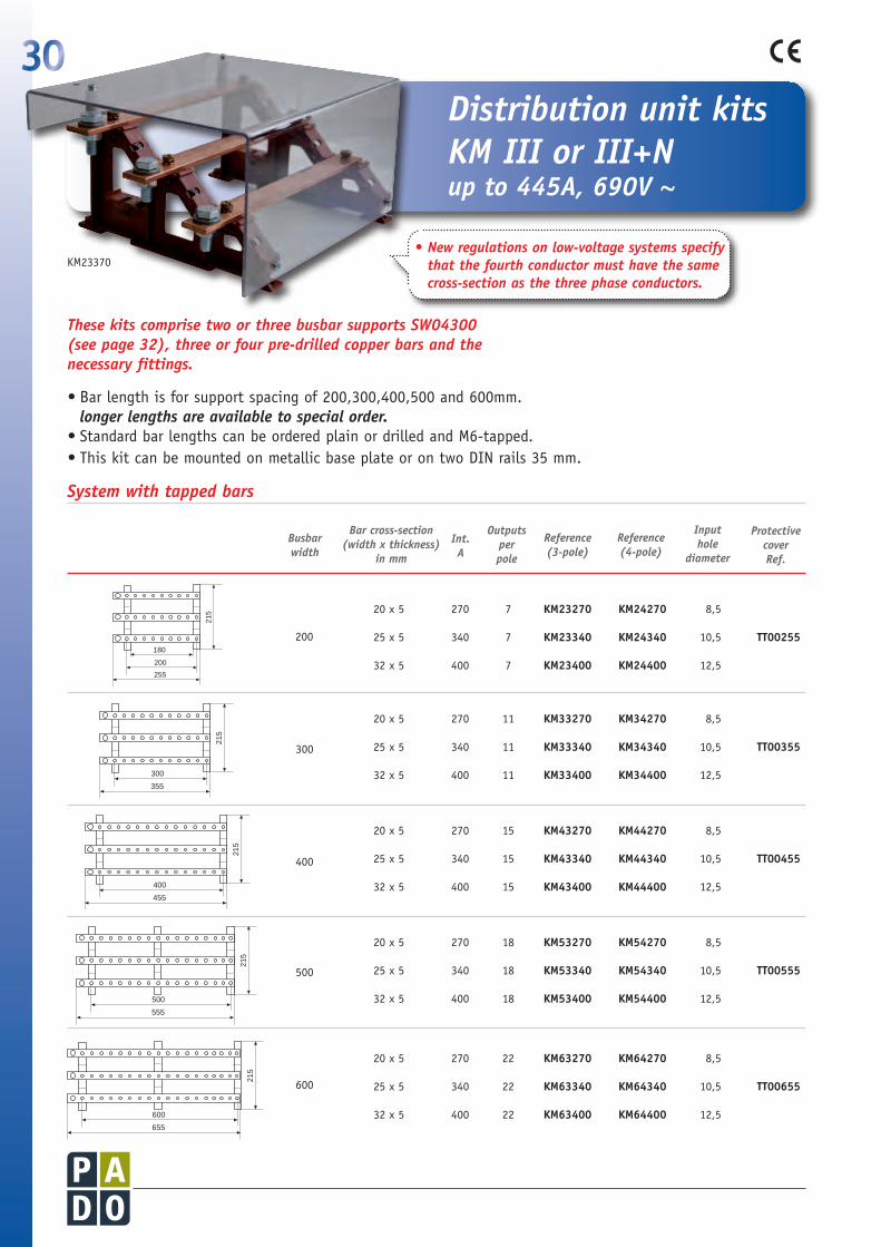
•Bar length is for support spacing of 200,300,400,500 and 600mm. longerlengthsareavailabletospecialorder.
•Standard bar lengths can be ordered plain or drilled and M6-tapped. •This kit can be mounted on metallic base plate or on two DIN rails 35 mm.
10
6230
10
6186
46PerfilDIN35 mm
14 1640
1827
616
1414
40
6
M69950
19
16
35
32
230
32
35190
35
32
320
Perfil DIN35 mm
Distributionunitkits KMIIIorIII+N upto445A,690V~
•Newregulationsonlow-voltagesystemsspecifythatthefourthconductormusthavethesamecross-sectionasthethreephaseconductors.
ThesekitscomprisetwoorthreebusbarsupportsSW04300 (seepage32),threeorfourpre-drilledcopperbarsandthenecessaryfittings.
Input hole
diameter
Reference(4-pole)
ProtectivecoverRef.
Reference(3-pole)
Int.A
Busbar width
Outputsper pole
Barcross-section(widthxthickness)
in mm
20 x 5 270 7 KM23270 KM24270 8,5
25 x 5 340 7 KM23340 KM24340 10,5 TT00255
32 x 5 400 7 KM23400 KM24400 12,5
20 x 5 270 11 KM33270 KM34270 8,5
25 x 5 340 11 KM33340 KM34340 10,5 TT00355
32 x 5 400 11 KM33400 KM34400 12,5
20 x 5 270 15 KM43270 KM44270 8,5
25 x 5 340 15 KM43340 KM44340 10,5 TT00455
32 x 5 400 15 KM43400 KM44400 12,5
20 x 5 270 18 KM53270 KM54270 8,5
25 x 5 340 18 KM53340 KM54340 10,5 TT00555
32 x 5 400 18 KM53400 KM54400 12,5
20 x 5 270 22 KM63270 KM64270 8,5
25 x 5 340 22 KM63340 KM64340 10,5 TT00655
32 x 5 400 22 KM63400 KM64400 12,5
200
300
400
500
600
400
455
215
500
555
215
600
655
215
300
355
215
200
255
215
180
200
255
215
180
300
355
215
280
400
455
215
380
500
555
215
230 230
600
655
215
280 280
400
455
215
500
555
215
600
655
215
300
355
215
200
255
215
180
200
255
215
180
300
355
215
280
400
455
215
380
500
555
215
230 230
600
655
215
280 280
400
455
215
500
555
215
600
655
215
300
355
215
200
255
215
180
200
255
215
180
300
355
215
280
400
455
215
380
500
555
215
230 230
600
655
215
280 280
400
455
215
500
555
215
600
655
215
300
355
215
200
255
215
180
200
255
215
180
300
355
215
280
400
455
215
380
500
555
215
230 230
600
655
215
280 280
400
455
215
500
555
215
600
655
215
300
355
215
200
255
215
180
200
255
215
180
300
355
215
280
400
455
215
380
500
555
215
230 230
600
655
215
280 280
KM23370
Systemwithtappedbars
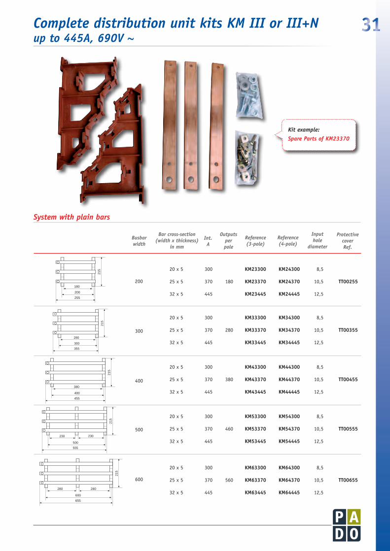
31CompletedistributionunitkitsKMIIIorIII+N upto445A,690V~
Input hole
diameter
Reference(4-pole)
ProtectivecoverRef.
Reference(3-pole)
Int.A
Busbar width
Outputsper pole
Barcross-section(widthxthickness)
in mm
20 x 5 300 KM23300 KM24300 8,5
25 x 5 370 180 KM23370 KM24370 10,5 TT00255
32 x 5 445 KM23445 KM24445 12,5
20 x 5 300 KM33300 KM34300 8,5
25 x 5 370 280 KM33370 KM34370 10,5 TT00355
32 x 5 445 KM33445 KM34445 12,5
20 x 5 300 KM43300 KM44300 8,5
25 x 5 370 380 KM43370 KM44370 10,5 TT00455
32 x 5 445 KM43445 KM44445 12,5
20 x 5 300 KM53300 KM54300 8,5
25 x 5 370 460 KM53370 KM54370 10,5 TT00555
32 x 5 445 KM53445 KM54445 12,5
20 x 5 300 KM63300 KM64300 8,5
25 x 5 370 560 KM63370 KM64370 10,5 TT00655
32 x 5 445 KM63445 KM64445 12,5
200
300
400
500
600
400
455
215
500
555
215
600
655
215
300
355
215
200
255
215
180
200
255
215
180
300
355
215
280
400
455
215
380
500
555
215
230 230
600
655
215
280 280
400
455
215
500
555
215
600
655
215
300
355
215
200
255
215
180
200
255
215
180
300
355
215
280
400
455
215
380
500
555
215
230 230
600
655
215
280 280
400
455
215
500
555
215
600
655
215
300
355
215
200
255
215
180
200
255
215
180
300
355
215
280
400
455
215
380
500
555
215
230 230
600
655
215
280 280
400
455
215
500
555
215
600
655
215
300
355
215
200
255
215
180
200
255
215
180
300
355
215
280
400
455
215
380
500
555
215
230 230
600
655
215
280 280
400
455
215
500
555
215
600
655
215
300
355
215
200
255
215
180
200
255
215
180
300
355
215
280
400
455
215
380
500
555
215
230 230
600
655
215
280 280
Systemwithplainbars
Kitexample:
SparePartsofKM23370

32ComponentsforKMseriesdistributors
10
6230
10
6186
46PerfilDIN35 mm
14 1640
1827
616
1414
40
6
M69950
19
16
35
32
230
32
35190
35
32
320
Perfil DIN35 mm
Fibreglassreinforced 6,6 polyamide, halogenfree.
•ThesupportscanbefastenedontothebaseplatedirectlyorbymeansofthepatentedWofixsystem on two 35 mm DIN rails spaced at 125 mm.
•Verytoughconstruction.•Specialdesigntoaccommodatecopperbarfittedat45ºorvertical.Inbothcases,theyare
mounted in a step configuration, for convenient, unobstructed wiring access.•Thesupportstakecopperbarin20x5mm,25x5mm,30x5mmand32x5mmdimensions
(slanting or vertical).•Oneofthefeetofthesupportincludesacouplingforoursingle-polesupportBD41216,providing
five-pole capabilities. Taking one bar 15x5 mm.•Bars fasten onto the support by means of special M6 bolts and nuts via 2 holes 6,5 mm in diameter.
+
A D
B
D
A B C D
TT00255 255 232 132 38TT00355 355 232 132 38TT00455 455 232 132 38TT00555 555 232 132 38TT00655 655 232 132 38
•Topreventcontactwithcopperphasebarsandinputandoutputterminals.•Suppliedwithinsulatingspacersandfasteningbolts.
PETG (unbreakable)
Stackable,slot-ininsulatingspacer
Height
10 mm EA00010
20 mm EA00020
SW04300
Transparentcovers
x 4
x 4
TR00620
+x 4

33
The supports as well as affording dielectric strength consistent with the voltages applied, busbar supports must also withstand the mechanical stresses arising from phase-to-phase or phase-to-earth short-circuits. Systems are designed on the basis of symmetrical short-circuit current Ik (measured in effective kA) and shock short-circuit current (dynamic).
Short-circuit handling capability depends on the busbar layout, cross-section and support spacing. The closer the supports, the greater the mechanical strength in withstanding the dynamic effects of short-circuit conditions. The table below shows short-circuit current-handling capability for different copper cross-sections, layouts and support spacing.
L = 200 mm L = 300 mm L = 400 mm
mm I”k Is I”k Is I”k Is AxG Amp. KA KA KA KA KA KA
20x5 300 21 46 21 46 21 46
25x5 370 25 62 21 46 21 46
30x5 425 25 62 25 61 21 46
32x5 445 25 62 25 61 21 46
Rectangularcopperbardimensions
Maximumratedcurrent*
* Withheatingupto40ºCatambienttemperatureof30ºC
TestcertificatesfromtheLGAIlaboratoryareavailableforinspectiononrequest.
Technicalinformationofinsulatorsupports
•Dielectricstrenght20Kvbetweenphases y19Kvphase/earth.
•TestedtostandardUNE-EN60947-1 Part83344.1º,paragraph3º,4000V/1minute.
•Maximumtemperature:220°C.
•Self-extinguishingVO.
•Colour:RedPantone499C.
Testedtostandard:UNEEN60947-1:1999Part8.343
Electrodynamicsshort-circuitcurrenthandlingcapacities forcopperbarsofdifferentdimensionswithdifferentsupportspacing.

34
Busbar widthmm.
Current(A)
Cross-sectionWidthxThickness
Plainbars
Tapped bars
Protective cover
300
300 20 x 5 HI34205 HR34205
TT03104 370 25 x 5 HI34255 HR34255
429 30 x 5 HI34305 HR34305
630 30 x 10 HI34310 HR34310
500
300 20 x 5 HI54205 HR54205
TT05104 370 25 x 5 HI54255 HR54255
429 30 x 5 HI54305 HR54305
630 30 x 10 HI54310 HR54310
700
300 20 x 5 HI74205 HR74205
TT07104 370 25 x 5 HI74255 HR74255
429 30 x 5 HI74305 HR74305
630 30 x 10 HI74310 HR74310
10
6230
10
6186
46PerfilDIN35 mm
14 1640
1827
616
1414
40
6
M69950
19
16
35
32
230
32
35190
35
32
320
Perfil DIN35 mm
Four-poledistributionunitkits upto630Aand690V~
•The copper bars can be plain or thread drilled M6.•Standard widths are 300, 500 and 700 mm. corresponding to cabinet
widths of 400, 600 and 800 mm respectively.•Systems for 1000 and 1200 mm cabinets are available to special order.• Very competitive prices.•All these kits take 60-system accessories ( J.Müller, Rittal, Weber, etc.)•Optional: Transparent cover covering all live parts, with fittings for raising
the cover by 15 to 25 mm, to fit input and output terminals.• Terminals available separately.
Thesekitscomprisetwoorthreefour-poleuniversalsupports(Ref.IS64845,seepage23),fourcopperbars(glossfinish),andM8screwswithfemalethreadM4forfixingtransparentcover.
DISTRIBUTINGQUARTERING
DETAILCOVERS
SystemIII+N

35
10
6230
10
6186
46PerfilDIN35 mm
14 1640
1827
616
1414
40
6
M69950
19
16
35
32
230
32
35190
35
32
320
Perfil DIN35 mm
Compactdistributionunits
•Wofix system (see page 44).•Specially designed 45mm high format for fitting on 35mm DIN system alongside modular devices.•All fixing points can be used.•Fixing system with no terminal damage.•Supplied complete with cover included.
Insulating support in halogenfree, fibreglassreinforced polyamide.
Cover in selfextinguishing polycarbonate.
125 A
1 input + 5 output per phase BD10124
1 input + 11 output per phase BD14124
160 A
1 input + 8 output per phase BD14164
125 A
1 input + 12 output (with neutral BD15012) see page 38 BD15124
1 input + 16 output (with neutral BD19016) see page 38 BD19124
160 A
1 input + 9 output (with neutral BD15012) BD15164
1 input + 12 output (with neutral BD19016) BD19164
Compactthreephaseorthree-phase-plus-neutraldistributionunits
Smallfour-pole(3p+N)distributionunitsspecialsfordinrail35mm
•For industrial applications.
•All fixing points can be used.
•Fixing system with no terminal damage.
•Easy base plate mounting or frame, by means of 2 M6 bolts.
•Can be fitted with Wofix system for 35 mm Din rail (ref. SW04051 see page 44)
•Can be fitted with neutral bar in two options.
•Supplied complete with cover included.
36
10
6230
10
6186
46PerfilDIN35 mm
14 1640
1827
616
1414
40
6
M69950
19
16
35
32
230
32
35190
35
32
320
Perfil DIN35 mm
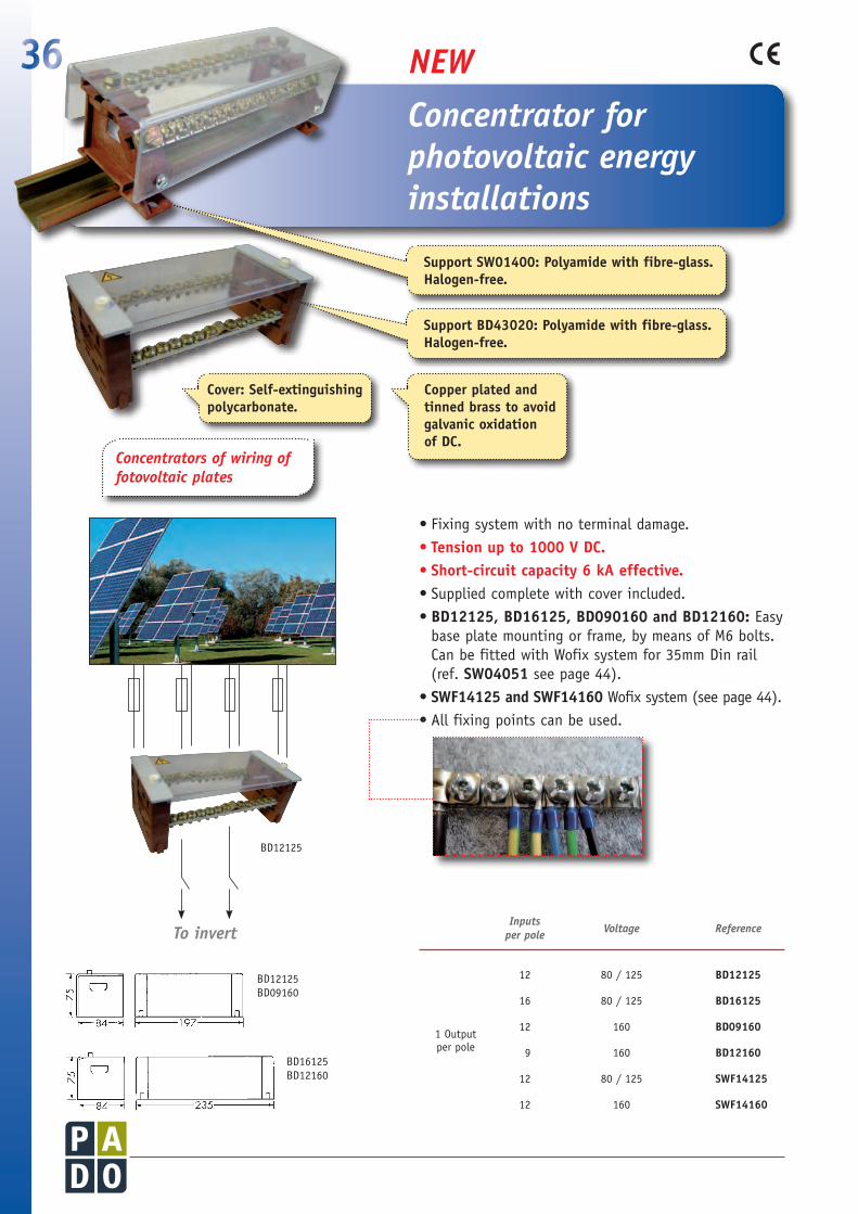
Concentratorforphotovoltaicenergyinstallations
Support BD43020: Polyamide with fibreglass. Halogenfree.
Support SW01400: Polyamide with fibreglass. Halogenfree.
Cover: Selfextinguishing polycarbonate.
Copper plated and tinned brass to avoid galvanic oxidation of DC.
•Fixing system with no terminal damage.• Tension up to 1000 V DC.• Shortcircuit capacity 6 kA effective.•Supplied complete with cover included.•BD12125, BD16125, BD090160 and BD12160: Easy
base plate mounting or frame, by means of M6 bolts. Can be fitted with Wofix system for 35mm Din rail (ref. SW04051 see page 44).
•SWF14125 and SWF14160 Wofix system (see page 44).•All fixing points can be used.
Concentratorsofwiringoffotovoltaicplates
InputsVoltage Reference perpole
12 80 / 125 BD12125
16 80 / 125 BD16125
1 Output
12 160 BD09160
per pole 9 160 BD12160
12 80 / 125 SWF14125
12 160 SWF14160
BD12125BD09160
BD16125BD12160
NEW
Toinvert
BD12125

37
Polyamide with fibreglass. Halogenfree.
Selfextinguishing and transparent polycarbonate
Polyamide + fibreglass, selfextinguishing Grey Ral 7032
TransparentcoversReversibleandextendabletotwoormoresupports.
10
6230
10
6186
46PerfilDIN35 mm
14 1640
1827
616
1414
40
6
M69950
19
16
35
32
230
32
35190
35
32
320
Perfil DIN35 mm
Distributionunitfittings
UniversalsupportBD43020
Complementpiece:BD43082.
10 Units
Usefuldimensions
A: 12 x 4 mm.B: 16 x 4 mm.C: 30 x 5 (o 10) mm. 25 x 5 (o 10) mm. 20 x 5 (o 10) mm.D: 6 x 10 mm.E: 15 x 5 mm.F: 12 x 5 mm.G: 10 x 3 mm. + 6 x 6 mm.
90
20
20387
53
53
87162
Nylon insulating bolts M6 x 12
•With 15 housings accommodating bar sizes from 6 x 6 to 30 x 10 mm.
• Suitable for fitting three-phase busbars up to 160 A.
• Easy base plate mounting by means of two M6 x 35 mm bolts (included).
• Can be fitted with Wofix system for 35mm Din rail.
(Ref. SW04051 page 44)
• Can be fitted with neutral bar with BD41216 (page 38)
• Accessories: cover (see bellow)
BD43175
BD43200

38 Distributionunitfittings
Dimensions CurrentsReference
mm take-offs
12 x 4 x 300 25 BD00300
12 x 4 x 500 45 BD00542
12 x 4 x 1000 91 BD01084
16 x 4 x 500 35 BD00534
16 x 4 x 1000 71 BD01068
Dimensions mm
Currentstake-offs
Dovetailonto Reference
12 x 4 x 190 1 inp. + 12 out. BD15124BD19124BD15164BD19164
(See page 35)
BD15012
12 x 4 x 230 1 inp. + 12 out. BD19016
12 x 4 x 300 2 inp. + 21 out.Serie KM
(See page 30)BD30300
Dimensionsmm
Tighteningtorque Mountedon Reference
12 x 22
5 Nm
BD00300
BD00542
BD01084
BD00020
10 x 32 BD00021
10 x 32 BD00023
15 x 38
6 Nm
Tapped bars each 25 mm
BD00025
15 x 26BD00534
BD01068
BD00030
15 x 41 BD00031
15 x 41 BD00033
•Each terminal screw tightens over two grooves, taking tipped wires.
• The M5 or M6 terminal screws have slot + pozidriv heads (patent MU 9303300)
Hard brass, copper plated and tinned
Test report APPLUS+ available
10 Units
10 Units
Polyamide + fibreglass, selfextinguishing .Halogenfree 690 V. 160° C
•For connecting input cables on distribution bars.
•Bolts included.
DistributionbarsEarth bars, for forming small distribution busbars (3P or 3P+N) or auxiliary supply subsystems.
MultipleconnexionbarsNeutral bars dovetail directly onto BD15124 (page 35) and KM distributors.
EarthordistributionbarsupportBD41216(12 x 4 or 16 x 4). Fastening bolt M5 x 20 included.
Straps
BD00
300
BD00
542
BD00
534
Galvanized and achromatized steel (CR3)

1039
ASSEMBLYANDWIRINGSOLUTIONSConsciousPADOofthedifficultiesthatfindthemajorityofmountersofelectricalequipmentintheirwork,isdevelopingtoaprogramofaccessories for the packing and the viring of the equipment. Thisprogramwillbeextendedandadaptingtotheneedsandrequirementsofthenewcomponents,untilbeingabletoofferaglobalsolutiontoalltheproblemsofassembly.
•Connectionterminals forflexiblebars pages40 - 41
•Wiringfittings-clamps page42
•Wiringsolutions page43
•WOFIXsystem page44
•Spacers page45
•Specialnutsandbolts page46
•Flexiblebardrillingtools page47
Four Wofix supports SW04050usedforfixingaIII-polesystemofflexiblebars

40
Directbolt-onconnectionsystemforcopperbusbarsystemcomprisingtwoflatbars10mmthick.Withnodrillingrequired.
10
6230
10
6186
46PerfilDIN35 mm
14 1640
1827
616
1414
40
6
M69950
19
16
35
32
230
32
35190
35
32
320
Perfil DIN35 mm
• Derivation possibilities: rigid bars, flexible bars, wire with terminal.
• Ideal for branch connections on existing systems.• Supplied completed with fittings.• Available with four different bolt lengths for bar widths of 40/50,
60, 80 and 100 mm wide (10 mm thick), and four types of clamp plate, for different widths of branch bar or cable.
Connectionterminalsforflexiblebars
•Single anchor-bolt fitting on double busbar system with bars 10 mm thick, for bolt or terminal branch connection of flexible or rigid conductors up to 32 mm wide.
•Double anchor –bolt fitting on double busbar system with bars 10 mm thick, for no-drilling branch connection of rigid or flexible bars up to 50mm wide.
Barwidthmm
Current (A)
UsefuldistributionwidthMax.min.
Reference
40 / 50
400 32
BD40050
60 BD60000
80 BD80000
100 BD10000
Barwidthmm
Current (A)
UsefuldistributionwidthMax.min.
Reference
40 / 50
600 30 BD24532800 40 BD245401000 50 BD24550
60
600 30 BD26032800 40 BD260401000 50 BD26050
80
600 30 BD28032800 40 BD280401000 50 BD28050
100
600 30 BD21032800 40 BD210401000 50 BD21050
Width A B
30 40 70 40 50 80 50 60 90
Ø M10
A
10,5 Ø
A B
50
Ø M10
A
10,5 Ø
A B
50
A
8090110130
Ø M10
A
10,5 Ø
A B
50
A
8090110130
Copper
1 Set
1 Set
ApplicationA
ApplicationB
Steel

41
•Small strap fitting onto main busbars.
• For branching up to small cables (1.5 to 6 mm2).
•Rated current: 200 A.
• Can be fitted on BD00030, BD00031, BD00033 (see page 38).
•For fitting distribution bars on flat copper bar.
• Branching of smaller cables from main phase bars, using BD01068 (see page 38) bars cut to the required length.
•Input or output terminals for cables leading directly from busbars.
• Copper bar 50 to 100 mm wide and 10 or 20 mm thick.
•For cable terminals leading from busbars.
• For bars of any dimension. Holes every 25 mm.
• It avoid the need for fitting terminals on cables, to prevent risk of poor contact.
• Takes two cables from 1,5 to 6 mm2.
Solutionsforassemblyandwiring
Copper bars 20 x 3 mm.
Clamp: galvanized and achromatized steel (CR3)Screw: Steel 8:8 M6x11
Tinned copperA
D
B
C
A
D
B
C
Dimensions AxBxCmm
DØmm Reference Packing
15 x 15 x 15 7 DM01515
20 x 20 x 20 9 DM02020
25 x 25 x 25 11 DM02525
30 x 30 x 30 13 DM03030
25 Units
12 Units
3 Units
4 Units
25 Units
10 Units
Self-locking clamp 185 mm2. BD01250
Self-locking clamp 300 mm2. BD01675
Separate clamp can be purchased BR01250
BR01675
StrapsfittingBD20320
Metalspacers
Self-lockingclamp
Self-lockingclampforcableterminalsleadingBR02024
Steel screw 8:8 M12 x 50 or M16 x 70.
Lock washers: steel

42 Wiringfittings-clamps
• These clamps are formed from one part in trivalent zinc plated steel and another in tinned brass, giving good contact with no induction problems.
• It is no necessary to drill the bars.
• Screws with hardened 8:8, with the tightening torque that ensures a sound junction between rigid and flexible bars.
• Not suitable for use with multi-strand cables.
• They comply with DIN43679 standard.
• For assembling and connecting flexible copper bars, with cheaper cost in their use.
•Clampsforconnectingrigidbarswithflexiblebars.
Tinned brass Galvanized and achromatized steel (CR3)
Hardened (8:8) M6 x 30 screws with captive grower washer.Tightening torque 6/8 Nm - Clampable thickness 20 mm.
30 x 40 10 x 20 BR23040 35 x 35 16 x 16 BR23535 35 x 40 16 x 20 BR23540 35 x 45 16 x 25 BR23545 35 x 52 16 x 32 BR23550
35 x 60 16 x 40 BR23560 35 x 70 16 x 50 BR23570 35 x 82 16 x 63 BR23582
40 x 40 20 x 20 BR24040 40 x 45 20 x 25 BR24045 40 x 52 20 x 32 BR24050
40 x 60 20 x 40 BR24060 40 x 70 20 x 50 BR24070 40 x 82 20 x 63 BR24082
45 x 45 25 x 25 BR24545 45 x 52 25 x 32 BR24550
45 x 60 25 x 40 BR24560 45 x 70 25 x 50 BR24570 45 x 82 25 x 63 BR24582 52 x 50 32 x 32 BR25050 52 x 60 32 x 40 BR25060 52 x 70 32 x 50 BR25070 52 x 82 32 x 63 BR25082
60 x 60 40 x 40 BR26060 60 x 70 40 x 50 BR26070 60 x 82 40 x 63 BR26082 70 x 70 50 x 50 BR27070 70 x 82 50 x 63 BR27082 80 x 82 60 x 63 BR28082
SIZEmm. Exterior Useful Reference Packing axb cxd
SIZEmm. Exterior Useful Reference Packing axb cxd
Hardened (8:8) M6 x 42 screws with captive grower washer.Tightening torque 6/8 Nm - Clampable thickness 30 mm.
35 x 60 16 x 40 BR33560 35 x 70 16 x 50 BR33570 35 x 82 16 x 63 BR33582 40 x 60 20 x 40 BR34060 40 x 70 20 x 50 BR34070 40 x 82 20 x 63 BR34082 45 x 60 25 x 40 BR34560 45 x 70 25 x 50 BR34570 45 x 82 25 x 63 BR34582 52 x 60 32 x 40 BR35060 52 x-70 32 x 50 BR35070 52 x 82 32 x 63 BR35082
60 x 60 40 x 40 BR36060 60 x 70 40 x 50 BR36070 60 x 82 40 x 63 BR36082 70 x 70 50 x 50 BR37070 70 x 82 50 x 63 BR37082 80 x 82 60 x 63 BR38082
Hardened (8:8) M8 x 45 screws with lock washer.Tightening torque 10/12 Nm - Clampable thickness 30 mm.
70 x 110 40 x 80 BR37011 70 x 130 40 x 100 BR37013 80 x 110 50 x 80 BR38011 80 x 130 50 x 100 BR38013 90 x 110 60 x 80 BR39011
Hardened (8:8) M10 x 45 screws with lock washer.Tightening torque 18/20 Nm - Clampable thickness 30 mm.
100 x 140 63 x 100 BR31014 NEW 120 x 120 80 x 80 BR31212 120 x 140 80 x 100 BR31214 140 x 140 100 x 100 BR31414
9 Units
6 Units6 Units
3 Units
3 Units
3 Units
9 Units
6 Units
9 Units
6 Units
3 Units
Available with M6 x 60 screws to special order
Clamps
d
c a
b
Clampsforconnectingrigidbarwithflexiblebar
43Wiringsolutions
Tinned brass
6,5
15
26
(4
1)
2
5
22
(3
2)
10 2
41
(3
8)
32
15 2
16 (20)6,5
10 2
5
16
(2
0)
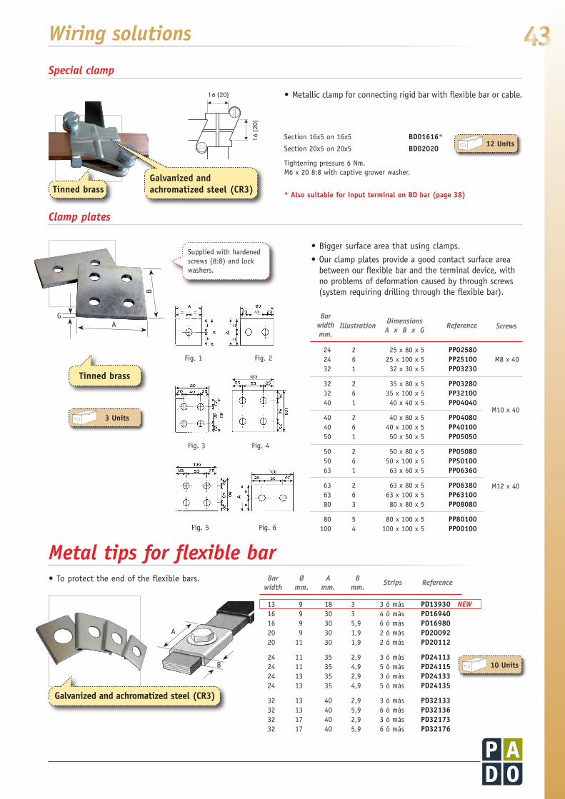
•Metallic clamp for connecting rigid bar with flexible bar or cable.
•Bigger surface area that using clamps.
•Our clamp plates provide a good contact surface area between our flexible bar and the terminal device, with no problems of deformation caused by through screws (system requiring drilling through the flexible bar).
•To protect the end of the flexible bars.
12 Units
3 Units
Section 16x5 on 16x5 BD01616*
Section 20x5 on 20x5 BD02020
Tightening pressure 6 Nm.M6 x 20 8:8 with captive grower washer.
* Also suitable for input terminal on BD bar (page 38)Tinned brass
Fig. 1
Fig. 4Fig. 3
Fig. 2
Fig. 6Fig. 5
B
GA
Supplied with hardened screws (8:8) and lock washers.
24 2 25 x 80 x 5 PP02580 24 6 25 x 100 x 5 PP25100 M8 x 40 32 1 32 x 30 x 5 PP03230
32 2 35 x 80 x 5 PP03280 32 6 35 x 100 x 5 PP32100 40 1 40 x 40 x 5 PP04040
40 2 40 x 80 x 5 PP04080 40 6 40 x 100 x 5 PP40100 50 1 50 x 50 x 5 PP05050
50 2 50 x 80 x 5 PP05080 50 6 50 x 100 x 5 PP50100 63 1 63 x 60 x 5 PP06360
63 2 63 x 80 x 5 PP06380 63 6 63 x 100 x 5 PP63100 80 3 80 x 80 x 5 PP08080
80 5 80 x 100 x 5 PP80100 100 4 100 x 100 x 5 PP00100
Barwidthmm.
IllustrationDimensionsAxBxG
Reference Screws
M10 x 40
M12 x 40
Metaltipsforflexiblebar
A
B 10 Units
Bar Ø A B Strips Reference width mm. mm. mm.
13 9 18 3 3 ó más PD13930 NEW 16 9 30 3 4 ó más PD16940 16 9 30 5,9 6 ó más PD16980 20 9 30 1,9 2 ó más PD20092 20 11 30 1,9 2 ó más PD20112
24 11 35 2,9 3 ó más PD24113 24 11 35 4,9 5 ó más PD24115 24 13 35 2,9 3 ó más PD24133 24 13 35 4,9 5 ó más PD24135
32 13 40 2,9 3 ó más PD32133 32 13 40 5,9 6 ó más PD32136 32 17 40 2,9 3 ó más PD32173 32 17 40 5,9 6 ó más PD32176
Galvanized and achromatized steel (CR3)
Specialclamp
Clampplates
Galvanized and achromatized steel (CR3)

44
WOFIX system provides a safe, simple and rapid solution for fastening components on a 35 mm Din rail. Components fastened using the system resist sideways, cross-wise and frontal tugs without detaching. Components are fitted and detached using a simple screwdriver.
10
6230
10
6186
46PerfilDIN35 mm
14 1640
1827
616
1414
40
6
M69950
19
16
35
32
230
32
35190
35
32
320
Perfil DIN35 mm
WOFIX® System
48
10
8 35,5
14
48
10
8 35,5
14
thread M6
10
6230
10
6186
46DINRail35 mm
14 1640
1827
616
1414
40
6
M69950
19
16
35
32
230
32
35190
35
32
320
DIN Rail35 mm
10
6230
10
6186
46DINRail35 mm
14 1640
1827
616
1414
40
6
M69950
19
16
35
32
230
32
35190
35
32
320
DIN Rail35 mm
SW04050
SW04051
SW01550
SW01555
•Can be coupled together for fastening one or more bars of any thickness or width. Locks onto 35 mm Din rail by means of roating clamp that prevents detachment under mechanical stress caused by short-circuit conditions.
•Cables, bars, etc. can be attached using adjustable straps. Ducts, relays, etc. can be fitted by means of screws.
•Convenient, trouble-free solution for fitting protective covers in metacrylate or macrolon, to protect against physical contact with busbars and other live parts in distribution units.
•Prevents sideways movement of electromechanical components such as relays, timers, automatic shut-off devices, differentials, terminals, etc. Can be numbered using 5 mm insulating tags.
4 Units
12 Units
12 Units
12 Units
Insulatingsupportforfasteningisolatedflexiblebars.
UniversalWofixsupportbaseplate
FasteningfitsontoaPADOPM-seriesbusbarinsulatorsupportplate forthepurposeofmountingaprotectivecover
Endfasteningforfittingon35mmDinrail.
Halogenfree, selfextinguishing fibreglassreinforced polyamide.
Halogenfree, selfextinguishing fibreglassreinforced polyamide.
Halogenfree, selfextinguishing fibreglassreinforced polyamide.
Selfextinguishing fibreglassreinforced polyamide.
45
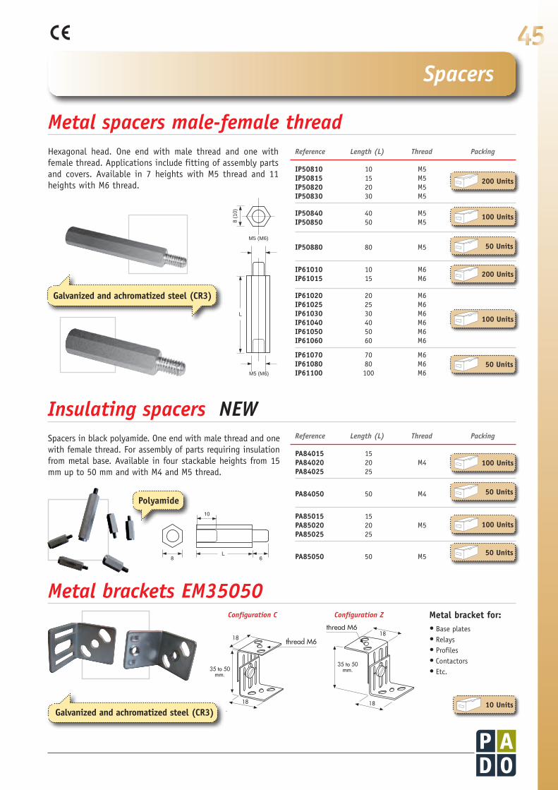
Metal bracket for: •Base plates•Relays•Profiles•Contactors•Etc.
18
35 to 50mm.
35 to 50mm.
18
18
18
thread M6
thread M618
35 to 50mm.
35 to 50mm.
18
18
18
thread M6
thread M6
10
6230
10
6186
46PerfilDIN35 mm
14 1640
1827
616
1414
40
6
M69950
19
16
35
32
230
32
35190
35
32
320
Perfil DIN35 mm
Spacers
10 Units
Metalspacersmale-femalethread
MetalbracketsEM35050
InsulatingspacersNEW
Hexagonal head. One end with male thread and one with female thread. Applications include fitting of assembly parts and covers. Available in 7 heights with M5 thread and 11 heights with M6 thread.
L
M5 (M6)
M5 (M6)
8 (1
0)
Spacers in black polyamide. One end with male thread and one with female thread. For assembly of parts requiring insulation from metal base. Available in four stackable heights from 15 mm up to 50 mm and with M4 and M5 thread.
��
��
�
Galvanized and achromatized steel (CR3)
IP50810 10 M5IP50815 15 M5IP50820 20 M5IP50830 30 M5
IP50840 40 M5IP50850 50 M5
IP50880 80 M5
IP61010 10 M6IP61015 15 M6
IP61020 20 M6IP61025 25 M6IP61030 30 M6IP61040 40 M6IP61050 50 M6IP61060 60 M6
IP61070 70 M6IP61080 80 M6IP61100 100 M6
Reference Length(L) Thread Packing
200 Units
100 Units
50 Units
200 Units
100 Units
50 Units
PA84015 15 PA84020 20 M4PA84025 25
PA84050 50 M4
PA85015 15 PA85020 20 M5PA85025 25
PA85050 50 M5
Reference Length(L) Thread Packing
100 Units
50 Units
100 Units
50 Units
Polyamide
ConfigurationC ConfigurationZ
Galvanized and achromatized steel (CR3)

46
d1 d2
M6 6,4 14 AR00060
M8 8,4 18 AR00080 M10 10,5 23 AR00100
M12 13 29 AR00120 M16 17 39 AR00160
d1 d2
M6 6,4 14 AR00061
M8 8,4 18 AR00081 M10 10,5 23 AR00101
M12 12,5 27 AR00121
Hexhead bolts (8:8) with captive grower washer
M6 x 20 TR00620 M6 x 25 TR00625 M6 x 30 TR00630 M6 x 35 TR00635 M6 x 42 TR00642
Panhead crossdrive bolts
M5 x 9 TR00509 M5 x 11 TR00511 M6 x 9 TR00609 M6 x 11 TR00611
Cylindricalhead bolts, DIN 84
M4 x 20 TR04020 M4 x 25 TR04025 M4 x 30 TR04030
M5 x 20 TR05020 M5 x 25 TR05025 M5 x 30 TR05030
M6 x 16 TR06016 M6 x 20 TR06020 M6 x 25 TR06025 M6 x 30 TR06030 M6 x 35 TR06035
Hexhead bolts (8:8) with interior M4 thread, DIN 933
M8 x 15 TR04815M8 x 20 TR04820
Hexhead bolts (8:8) partially thread, DIN 931
M10 x 120 TR10120M10 x 130 TR10130M10 x 140 TR10140M10 x 150 TR10150M10 x 160 TR10160M10 x 170 TR10170M10 x 180 TR10180M10 x 200 TR10200M10 x 220 TR10220
Hexagonal nuts DIN 9348
M4 TR00400 M5 TR00500 M6 TR00600 M8 TR00800
M10 TR01000
M12 TR01200 M16 TR01600
Hexhead bolts (8:8) DIN 933
M8 x 12 TR00812 M8 x 20 TR00820* M8 x 30 TR00830 M8 x 40 TR00840 M8 x 45 TR00845
M10 x 30 TR01030 M10 x 40 TR01040 M10 x 45 TR01045 M10 x 50 TR01050
M12 x 16 TR01216 M12 x 20 TR01220 M12 x 30 TR01230 M12 x 40 TR01240 M12 x 45 TR01245 M12 x 50 TR01250
M16 x 50 TR01650 M16 x 60 TR01660 M16 x 70 TR01670 * hardness 6:6
Embedded nuts
These special nuts are used for joining rigid copper bars. They embed into the copper so that bolts can be inserted and tightened using a single tool from a single position. Once tightened, the nut stays in place even if the bolt is removed.
ØDrillhole
M6 8,5 mm TE00060 M8 10 mm TE00080
M10 13 mm TE00100 M12 15 mm TE00120
d 1
d 2
Lock washers DIN 6796.Special for connecting rigid copper bars.
Star lock washers
10
6230
10
6186
46PerfilDIN35 mm
14 1640
1827
616
1414
40
6
M69950
19
16
35
32
230
32
35190
35
32
320
Perfil DIN35 mm
Specialnutsandbolts
100 Units
100 Units
100 Units
100 Units
100 Units
100 Units
50 Units
50 Units
25 Units
25 Units
25 Units
25 Units
25 Units
10 Units
50 Units
50 Units
50 Units
50 Units
50 Units
Galvanized and achromatized steel (CR3)

47
UT11610 16 6 / 8 UT12010 20 8 / 10 / 12
UT12410 24 8 / 10 / 12 UT13210 32 10 / 12
UT14010 40 10 / 12 UT15010 50 10 / 12 UT16310 63 10 / 12
UT25010 50 10 / 12 x 2 25 UT26310 63 10 / 12 x 2 30
UT28010 80 10 / 12 x 2 40 UT21001 100 10 / 12 x 2 50
UT00600 Drill guide 6 mm. UT00800 Drill guide 8 mm.
UT01000 Drill guide 10 mm. UT01200 Drill guide 12 mm.
10
6230
10
6186
46PerfilDIN35 mm
14 1640
1827
616
1414
40
6
M69950
19
16
35
32
230
32
35190
35
32
320
Perfil DIN35 mm
Flexiblebar drillingtools
1Guide
2Guides
Accessories
Bettersupportforabettercomfort
Barwidthmm.
UsualsupplyKitsguidesØ Spacing
Barwidthmm.
UsualsupplyKitsguidesØ
Body in F1 steel
Tospecialorder
Wecanmachineanytypeofrigidorflexiblecopperbartocustomers.
Specialrequirements,workingtosupplieddrawings.
Pleaseenquireforpricesanddeliverytimes.
Guide in special hardened galvanized and achromatized steel (CR3)
48
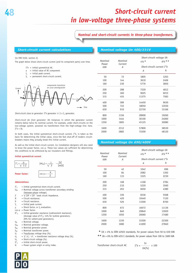
* Uk = 4% to DIN 42503 standards, for power values from 50 to 630 kVA
** Uk = 6% to DIN 42511 standards, for power values from 100 to 1600 kVA
Transformer short-circuit AC
Short-circuitcurrentcalculations NominalvoltageUn400/231V
NominalvoltageUn690/400V
(to VDE 0102, section 2)
The graph below shows short-circuit current (and its component parts) over time.
I”k = initial symmetrical AC.a = initial value of DC component.Is
= initial peak current.Ik = permanent short-circuit current.
Short-circuit close to generator: I”k generator M 2 x In generator.
Short-circuit far from generator: All instances in which the generator current remains below twice its nominal current. For example, under short-circuits on the low-voltage system, powered via transformers from the high-voltage line: here, I”k = Ik.
In both cases, the initial symmetrical short-circuit current, I”k, is taken as the basis for determining the initial value, since the fast shut-off of modern circuit-breakers means they actually break this initial current.
As well as the initial short-circuit current, Icc installation designers will also need to know the power factor, cos ϕ. These two values are sufficient for determining the conditions to be withstood by our insulators and fittings.
Initial symmetrical current
Power factor:
Abbreviations:
I”k = Initial symmetrical short-circuit current.UNT = Nominal voltage across transformer secondary winding (between-phase voltage).Z = ΣR2 + ΣX2 total circuit impedance.R = Circuit resistance.X = Circuit reactance.Is
= Initial peak current.χ = Shock factor, or Is evaluation.cos ϕ = Power factor.X”d = Initial generator reactance (subtransient reactance). (Average value of X”d: 14% for turbine generators; 20% for salient-pole generators).UN = Nominal voltage.UNG = Nominal generator voltage.SNG
= Nominal generator power.SNT
= Nominal transformer power.Ur = Transformer voltage drop (%).Ux = u2
k - u2r = transformer reactance voltage drop (%).
Uk = Short-circuit voltage (%).S”k = Initial short-circuit power.Q = Power system origin or entry index.
EFFFFFFFFF
EFFFFFFF
1 [V][kAeff] = ––––– –––––
EFFF
3 [mh]
UI”k
= –––––– EFFFF
3 Z
Rcos ϕ
= –––––
Z
componente transitoriaen curso amortiguaciónCurrent
Time
α
Is
I”kIk
Ik
In
Uk(%)x 100 I”k =
Short-circuitvoltageUk
4%* 6%**Short-circuitcurrentI”k
A A
NominalCurrent
A
NominalPowerkVA
50 72 1805 1203 100 144 3610 2406 160 230 5776 3850
200 288 7220 4812 250 360 9025 6015 315 455 11375 7583
400 589 14450 9630 500 722 18050 12030 630 910 22750 15166
800 1156 28900 19260 1000 1444 36100 24060 1250 1805 45125 30080
1600 2312 57800 38530 2000 2882 72200 48120
Short-circuitvoltageUk
4%* 6%**Short-circuitcurrentI”k
A A
NominalCurrent
A
NominalPowerkVA
50 42 1042 696 100 84 2082 1392 160 133 3325 2230
200 168 4168 2784 250 210 5220 3560 315 263 6650 4380
400 336 8336 5568 500 420 10440 7120 630 526 13300 8760
800 672 16672 11136 1000 840 20840 13920 1250 1050 26060 17480
1600 1330 33300 22300 2000 1680 41690 27840
Short-circuitcurrent inlow-voltagethree-phasesystems
Nominalandshort-circuitcurrentsinthree-phasetransformers.

49
10
Alphanumericindex

50 Alphanumericindex
AB
AB00620 25 12
AB00625 25 12
AB00630 25 12
AB00830 25 12 0,048
AB00835 25 12 0,053
AB00840 25 12 0,080
AB01040 25 12
AB01050 25 12 0,148
AB01260 25 12 0,180
ABP
ABP00620 25 12
ABP00625 25 12
ABP00630 25 12
ABP00830 25 12
ABP00835 25 12
ABP00840 25 12
ABP01040 25 12
ABP01050 25 12
ABP01060 25 12
ABP01270 25 12
ABP01280 25 12
ABP12100 25 12
AC
AC03010 10 15 0,384
AC03805 10 12 0,482
AC04010 10 15 0,365
AC04565 10 15 0,333
AC05010 10 15 0,377
AC05012 10 15 0,370
AC05020 10 15 0,342
AC05024 10 15 0,330
AC06010 10 15 0,372
AC06020 10 15 0,328
AC11001 10 12 0,516
AC18010 10 12 0,513
AC21001 10 12 0,400
AC23010 10 15 0,361
AC23210 10 15 0,352
AC24010 10 15 0,340
AC25010 10 15 0,325
AC26010 10 15 0,305
AC28010 10 12 0,465
AC31005 10 12 0,448
AC33310 10 12 0,484
AF
AF00830 25 12 0,050
AF00840 25 12 0,064
AF01040 25 12 0,113
AF01250 25 12 0,284
AF01260 25 12 0,336
AF01270 25 12 0,393
AF01280 25 12 0,451
AF10340 25 12 0,071
AF12460 25 12 0,157
AF28040 27 12
AF28050 27 12
AF28060 27 12
AF28070 27 12
AF28080 27 12
AP
AP03010 10 15 0,350
AP03805 10 12 0,365
AP04010 10 15 0,336
AP04565 10 15 0,301
AP05010 10 15 0,329
AP05012 10 15 0,319
AP05020 10 15 0,301
AP05024 10 15 0,288
AP06010 10 15 0,322
AP06020 10 15 0,280
AP11001 10 12 0,397
AP18010 10 12 0,429
AP21001 10 12 0,310
AP23010 10 15 0,310
AP23210 10 15 0,325
AP24010 10 15 0,294
AP25010 10 15 0,285
AP26010 10 15 0,264
AP28010 10 12 0,346
AP31005 10 12 0,353
AP33310 10 12 0,388
AR
AR00060 46 100 0,001
AR00061 46 100
AR00080 46 50 0,003
AR00081 46 50
AR00100 46 50 0,006
AR00101 46 50
AR00120 46 25 0,012
AR00121 46 25
AR00160 46 12 0,029
AT
AT20520 24 12
AT20525 24 12
AT20625 24 12 0,024
AT20630 24 12 0,028
AT20635 24 12 0,032
AT20640 24 12 0,038
AT20645 24 12 0,040
AT20650 24 12 0,047
AT20655 24 12 0,049
AT20660 24 12 0,053
AT25825 24 12
AT25830 24 12
AT25835 24 12 0,047
AT25840 24 12 0,054
AT25845 24 12 0,059
AT25850 24 12 0,064
AT25855 24 12
AT25860 24 12 0,078
AT35040 24 12 0,097
AT35045 24 12 0,102
AT35050 24 12 0,109
AT35055 24 12 0,118
AT35060 24 12 0,138
AT45121 24 12 0,349
AT45250 24 12 0,173
AT45255 24 12 0,191
AT45260 24 12 0,203
BD
BD00020 38 10 0,010
BD00021 38 10 0,013
BD00023 38 10 0,013
BD00025 38 10 0,013
BD00030 38 10 0,016
BD00031 38 10 0,020
BD00033 38 10 0,020
BD00300 38 10 0,186
BD00534 38 10 0,399
BD00542 38 10 0,301
BD01068 38 10 0,772
BD01084 38 10 0,585
BD01250 41 3 0,122
BD01616 43 12 0,068
BD01675 41 3 0,250
BD02020 43 12 0,080
BD09160 36 1
BD10000 40 1 jg. 0,138
BD10124 35 1 0,330
BD12125 36 1
BD12160 36 1
BD14124 35 1 0,520
BD14164 35 1 0,610
BD15012 38 1 0,148
BD15124 35 1 0,620
BD15164 35 1 0,753
BD16125 36 1
BD19016 38 1 0,142
BD19124 35 1 0,725
BD19164 35 1 0,875
BD20320 41 4 0,160
BD21032 40 1 jg. 0,275
BD21040 40 1 jg. 0,285
BD21050 40 1 jg.
BD24532 40 1 jg. 0,227
BD24540 40 1 jg. 0,237
BD24550 40 1 jg.
BD26032 40 1 jg. 0,237
BD26040 40 1 jg. 0,247
BD26050 40 1 jg.
BD28032 40 1 jg. 0,262
BD28040 40 1 jg. 0,272
BD28050 40 1 jg.
BD30300 38 1 0,216
BD40050 40 1 jg. 0,108
BD41216 38 12 0,022
BD43020 37 10 0,110
BD43082 37 1 jg. 0,033
BD43175 37 1 0,042
BD43200 37 1 0,053
BD60000 40 1 jg. 0,113
BD80000 40 1 jg. 0,125
BR
BR01250 41 10 0,031
BR01675 41 10 0,037
BR02024 41 25 0,020
BR23040 42 9 0,110
BR23535 42 9 0,126
BR23540 42 9 0,140
BR23545 42 9 0,155
BR23550 42 9 0,174
BR23560 42 6 0,199
BR23570 42 6 0,224
BR23582 42 6 0,263
BR24040 42 9 0,155
BR24045 42 9 0,171
BR24050 42 9 0,191
BR24060 42 6 0,220
BR24070 42 6 0,252
BR24082 42 6 0,294
BR24545 42 9 0,190
BR24550 42 9 0,215
BR24560 42 6 0,246
BR24570 42 6 0,280
BR24582 42 6 0,326
BR25050 42 6 0,233
BR25060 42 6 0,266
BR25070 42 6 0,300
BR25082 42 6 0,354
BR26060 42 3 0,323
BR26070 42 3 0,373
BR26082 42 3 0,435
BR27070 42 3 0,434
Packing UnitItem Page Unit Weight Kg.
Packing UnitItem Page Unit Weight Kg.
Packing UnitItem Page Unit Weight Kg.
Packing UnitItem Page Unit Weight Kg.

51Alphanumericindex
BR27082 42 3 0,506
BR28082 42 3 0,571
BR31014 42 3
BR31212 42 3 1,539
BR31214 42 3 1,800
BR31414 42 3 2,100
BR33560 42 6 0,208
BR33570 42 6 0,232
BR33582 42 6 0,272
BR34060 42 6 0,228
BR34070 42 6 0,260
BR34082 42 6 0,302
BR34560 42 6 0,254
BR34570 42 6 0,290
BR34582 42 6 0,334
BR35060 42 6 0,274
BR35070 42 6 0,310
BR35082 42 6 0,362
BR36060 42 3 0,332
BR36070 42 3 0,382
BR36082 42 3 0,445
BR37011 42 3 0,829
BR37013 42 3 0,960
BR37070 42 3 0,444
BR37082 42 3 0,516
BR38011 42 3 0,939
BR38013 42 3 1,089
BR38082 42 3 0,581
BR39011 42 3
DM
DM01515 41 25 0,024
DM02020 41 25
DM02525 41 12
DM03030 41 12 0,195
EA
EA00010 32 25 0,002
EA00020 32 25 0,003
EM
EM00420 21 2 0,052
EM00430 21 2
EM00500 17 1
EM00600 17 1
EM00601 17 1
EM00800 17 1
EM35050 45 10 0,035
ES
ES00610 24 12
ES00620 24 12
ES00630 24 12
ES00816 24 12
ES00820 24 12
ES00830 24 12
ES01020 24 12
ES01030 24 12
ES01230 24 12
ES01240 24 12
HI
HI34205 34 1
HI34255 34 1
HI34305 34 1
HI34310 34 1
HI54205 34 1
HI54255 34 1
HI54305 34 1
HI54310 34 1
HI74205 34 1
HI74255 34 1
HI74305 34 1
HI74310 34 1
HR
HR34205 34 1
HR34255 34 1
HR34305 34 1
HR34310 34 1
HR54205 34 1
HR54255 34 1
HR54305 34 1
HR54310 34 1
HR74205 34 1
HR74255 34 1
HR74305 34 1
HR74310 34 1
IA
IA04050 25 3
IP
IP50810 45 200
IP50815 45 200
IP50820 45 200
IP50830 45 200
IP50840 45 100
IP50850 45 100
IP50880 45 100
IP61010 45 100
IP61015 45 100
IP61020 45 100
IP61025 45 100
IP61030 45 100
IP61040 45 100
IP61050 45 100
IP61060 45 100
IP61070 45 100
IP61080 45 100
IP61100 45 100
IS
IS00040 17 1
IS00050 17 1
IS00060 17 1
IS00080 17 1
IS00100 17 1
IS00125 17 1
IS04525 23 1
IS04630 23 1
IS04845 23 1
IS11306 16 4
IS12406 16 4
IS30206 16 4
IS31306 16 4
IS32306 16 4
IS41106 16 4
IS41205 16 4
IS42306 16 4
IS64628 23 1
IS64845 23 1
KM
KM23270 30 1
KM23300 31 1
KM23340 30 1
KM23370 31 1
KM23400 30 1
KM23445 31 1
KM24270 30 1
KM24300 31 1
KM24340 30 1
KM24370 31 1
KM24400 30 1
KM24445 31 1
KM33270 30 1
KM33300 31 1
KM33340 30 1
KM33370 31 1
KM33400 30 1
KM33445 31 1
KM34270 30 1
KM34300 31 1
KM34340 30 1
KM34370 31 1
KM34400 30 1
KM34445 31 1
KM43270 30 1
KM43300 31 1
KM43340 30 1
KM43370 31 1
KM43400 30 1
KM43445 31 1
KM44270 30 1
KM44300 31 1
KM44340 30 1
KM44370 31 1
KM44400 30 1
KM44445 31 1
KM53270 30 1
KM53300 31 1
KM53340 30 1
KM53370 31 1
KM53400 30 1
KM53445 31 1
KM54270 30 1
KM54300 31 1
KM54340 30 1
KM54370 31 1
KM54400 30 1
KM54445 31 1
KM63270 30 1
KM63300 31 1
KM63340 30 1
KM63370 31 1
KM63400 30 1
KM63445 31 1
KM64270 30 1
KM64300 31 1
KM64340 30 1
KM64370 31 1
KM64400 30 1
KM64445 31 1
MT
MT01000 26 10
MT02000 26 10
MT06075 26 10 0,318
MT06090 26 10 0,387
MT60130 26 5
MT70210 26 2
MT80300 26 2
PA
PA84015 45 100
PA84020 45 100
PA84025 45 100
Packing UnitItem Page Unit Weight Kg.
Packing UnitItem Page Unit Weight Kg.
Packing UnitItem Page Unit Weight Kg.
Packing UnitItem Page Unit Weight Kg.

52 Alphanumericindex
PA84050 45 50
PA85015 45 100
PA85020 45 100
PA85025 45 100
PA85050 45 50
PB
PB21030 27 1 jg.
PB21040 27 1 jg.
PB21050 27 1 jg.
PB21060 27 1 jg.
PB21080 27 1 jg.
PB21100 27 1 jg.
PB28030 27 1 jg.
PB28040 27 1 jg.
PB28050 27 1 jg.
PB28060 27 1 jg.
PB28080 27 1 jg.
PB28100 27 1 jg.
PD
PD13930 43 10
PD16940 43 10 0,007
PD16980 43 10 0,010
PD20092 43 10 0,008
PD20112 43 10 0,008
PD24113 43 10 0,012
PD24115 43 10 0,013
PD24133 43 10 0,011
PD24135 43 10 0,013
PD32133 43 10 0,023
PD32136 43 10 0,026
PD32173 43 10 0,021
PD32176 43 10 0,025
PM
PM00150 8 1 0,175
PM00170 8 1 0,166
PM01000 7 1 0,555
PM01001R 9 1 0,845
PM01002L 9 1 0,845
PM01003R 8 1 0,428
PM01004L 8 1 0,428
PM01005R 8 1 0,643
PM01006L 8 1 0,643
PM01007R 9 1 0,510
PM01008L 9 1 0,510
PM02000 7 1 0,915
PM02001R 9 1 0,910
PM02002L 9 1 0,910
PM02003R 9 1 0,850
PM02004L 9 1 0,850
PM02005R 9 1 0,910
PM02006L 9 1 0,910
PM03130 7 1 0,657
PM03150 7 1 0,645
PM03153 7 1 0,485
PM03161 8 1 0,702
PM03170 7 1 0,892
PM03228 9 1 1,217
PM03260 9 1 1,323
PM04150 7 1 0,805
PM04153 8 1 0,490
PM04170 7 1 0,983
PM04173 8 1 0,848
PM04173/B 8 1 0,848
PM06170 7 1 1,950
PM08170 7 1 2,160
PP
PP00100 43 3 0,630
PP02580 43 3 0,095
PP03230 43 3 0,064
PP03280 43 3
PP04040 43 3 0,170
PP04080 43 3
PP05050 43 3 0,127
PP05080 43 3 0,220
PP06360 43 3 0,200
PP06380 43 3 0,300
PP08080 43 3 0,475
PP25100 43 3
PP32100 43 3
PP40100 43 3
PP50100 43 3 0,260
PP63100 43 3
PP80100 43 3
SE
SE00215 22 10 0,048
SE00225 22 6 0,112
SE00420 21 12 0,165
SE00430 21 2 0,412
SE00440 21 2 0,610
SE00450 21 2 1,150
SE00525 22 10 0,164
SE30430 23 2
SE30440 23 2
SE35450 23 2
SM
SM00001 15 1 jg.
SM00002 15 1 jg.
SM00003 15 1 jg.
SM00004 15 1 jg.
SM00310 15
SM68100 15
SW
SW01400 36
SW01550 44 12 0,014
SW01555 44 12 0,014
SW04050 44 4 0,038
SW04051 44 12 0,016
SW04300 32 12 0,144
SW14125 36 1
SW14160 36 1
TE
TE00060 46 50 0,001
TE00080 46 50 0,002
TE00100 46 25 0,006
TE00120 46 25 0,008
TR
TR00400 46 100 0,001
TR00500 46 100 0,001
TR00509 46 50 0,003
TR00511 46 50 0,003
TR00600 46 100 0,002
TR00609 46 50 0,005
TR00611 46 50 0,005
TR00620 46 50 0,006
TR00625 46 50 0,007
TR00630 46 50 0,008
TR00635 46 50
TR00642 46 50 0,010
TR00800 46 100 0,005
TR00812 46 100
TR00820 46 100 0,012
TR00830 46 100 0,015
TR00840 46 100 0,018
TR00845 46 100 0,020
TR01000 46 50 0,010
TR01030 46 50 0,027
TR01040 46 50 0,030
TR01045 46 50 0,035
TR01050 46 50 0,036
TR01200 46 50 0,016
TR01216 46 50
TR01220 46 100
TR01230 46 25 0,040
TR01240 46 25 0,045
TR01245 46 25 0,049
TR01250 46 25 0,052
TR01600 46 25 0,029
TR01650 46 10 0,102
TR01660 46 10 0,117
TR01670 46 10 0,127
TR04020 46 100 0,002
TR04025 46 100 0,002
TR04030 46 100 0,003
TR04815 46 100
TR04820 46 100
TR05020 46 100 0,004
TR05025 46 100 0,004
TR05030 46 100 0,005
TR06016 46
TR06020 46 50 0,006
TR06025 46 100 0,007
TR06030 46 50 0,008
TR06035 46 50 0,008
TR08020 46 50 0,012
TR10120 46 1
TR10130 46 1
TR10140 46 1
TR10150 46 1
TR10160 46 1
TR10170 46 1
TR10180 46 1
TR10200 46 1
TR10220 46 1
TT
TT00255 32 1 0,345
TT00355 32 1 0,477
TT00455 32 1 0,651
TT00555 32 1 0,767
TT00655 32 1 0,939
TT03104 34 1
TT05104 34 1
TT07104 34 1
UT
UT00600 47 1 jg. 0,063
UT00800 47 1 jg. 0,080
UT01000 47 1 jg. 0,070
UT01200 47 1 jg. 0,059
UT11610 47 1 0,366
UT12010 47 1 0,433
UT12410 47 1 0,543
UT13210 47 1 0,479
UT14010 47 1 0,524
UT15010 47 1 0,535
UT16310 47 1 0,809
UT21001 47 1
UT25010 47 1
UT26310 47 1 0,889
UT28010 47 1
Packing UnitItem Page Unit Weight Kg.
Packing UnitItem Page Unit Weight Kg.
Packing UnitItem Page Unit Weight Kg.
Packing UnitItem Page Unit Weight Kg.

Electricalfittings 10
Components for low-voltage distribution systems and medium-voltage insulators
June 2009
Dealer and technical service for Spain:
Francesc Samaranch, 11, Nave D - 08750 MOLINS DE REI (Barcelona) - SpainPhone +34 93 680 15 64 - Fax +34 93 680 04 39 - E-mail: [email protected] / [email protected] de Navacerrada, 16 - 28850 TORREJÓN DE ARDOZ (Madrid) - SpainPhone +34 91 676 21 89 - Fax +34 91 656 31 79 - E-mail: [email protected]
•Photographiesgentilityofthecompanies: T.S.K. of Gijón EMTE, S.A.
Distribution center in Aceralia
Systemofdistribution ofbusbarsinstalled indiverseequipment
Control center of motors in Aceralia
Control center of motors in Aceralia
Distribution center Barranco of Tirajana-Felguera
One of the installled equipment of distribution in the Liceo of Barcelona
Detail transformation center Barranco of Tirajana-Felguera
Constructive detail with the systems “PARALEL 170” and “EQUILATER 170”
ForGermany: JITEX Elektrovertrieb G.m.b.H. Gewerbepark Wagnerbruch, 4 42279 WuppertalFor France: FLOBEX FRANCE, 15, Chemin de la Montée Girard 42420 LORETTEFor Chile: NDU Ingeniería Ltda. Santa Elisa 498 - La Cisterna - SantiagoFor Sweden: BEVING ELEKTRONIK, Jägerhorns Väg 8 14175 Rungens KurvaForItaly: ITALWEBER, Via Risorgimento 84, 20017 RHO, MilanoFor Israel: KATZENSTEIN ADLER, 4 Haomanut St. industrial Park Kiryat Nordau, P.O.Box 6145 NETANYA 42504ForPortugal: Next incorporationn