System SF 50 non insulated aluminum folding door SF 50 offers optimum stability, burglar resistance...
50
Folding Sliding Door System System SF 50 Non Insulated Aluminum System
Transcript of System SF 50 non insulated aluminum folding door SF 50 offers optimum stability, burglar resistance...

Folding Sliding Door SystemSystem SF 50
Non Insulated Aluminum System


IndexDescription Page
General information & product features 1.4-1.8
Testing 1.9-1.11
Technical Information 1.13-1.22
Measurement 2.1-2.2
Assembly instructions 3.1-3.13
Maintenance and servicing instructions 4.1-4.4
Warranty 5.1-5.2
Terms of sale 6.1-6.5

1.4
Technical modifications and errors reserved.
Glazed Folding DoorsThe advantage of the SUNFLEX folding sliding systems is their large selection of layouts and options. Whether different glass thicknesses or materials, there is the right product for every requirement. The large-scale glazing can be opened and closed comfortably by means of the interconnected panels. A transparent all-round multifunctional system with a guarantee for quality and longevity.
System information
Flush aluminum construction Perfectly matching components Low construction depths and slim profile designs Choice of inward or outward opening folding panels Panel distribution and folding direction of panels freely selectable Storm-proof and burglary-resistant metal fittings Height of element up to 12’ (3600 mm) Various glazing types, lock types, colors, finishes, wood types, etc. possible Easy assembly Burglary resistant up to resistance class 2 in accordance with
DIN V ENV 1627-1630* DP +/- 60 psf rated and tested in accordance to AAMA/WDMA/CSA 101/I.S.2/A440-05 Sound transmission control of STC 36 with STC 36 glass
Tested SUNFLEX quality
1.5
Technical modifications and errors reserved.
Operation
Opening of the first panel Folding of the hinge connected panels Parking of the folded panels
Horizontal sections
Example of threshold options

1.6
Technical modifications and errors reserved.
Corner angles 90°-180° with or without corner post
Typ I
Typ I
Typ I
Typ I
Typ A
Typ A
Typ A
Typ A
Segmented systems
Corner angles 90°-180°
Typ A = Outward opening of panels Typ I = Inward opening of panelsOther floor plan geometries upon request

1.7
Technical modifications and errors reserved.
Mushroom-head lock for optimal tightness and increased burglar resistance
Different lock and handle options available
Burglar resistant fittings Panel catcher for additional security to fix the pass door to the adjacent panel
1
4
2
3
4
6
6
7
7
8
8
3
2
2
1
5

1.8
Technical modifications and errors reserved.
Basic SUNFLEX handle series
Assembly shoes allow a fast assembly and precise adjustment of the vertical frame profiles
Post installation height adjustments possible on running mechanisms, in case of structure settling
Twin-lock mechanism for additional burglar resistance option available
Optional security package for maximum burglar resistance up to resistance class 2 (as per European standards)
The non insulated aluminum folding door SF 50 offers optimum stability, burglar resistance as well as high operating tightness. The SF 50 is suitable for different applications such as balcony glazings or patio doors.
7
5
8
6

1.9
Technical modifications and errors reserved.
PERFORMANCE & TESTING RESULTS
tested SUNFLEX quality
General Product Performance
Product Type: Non Insulated Aluminum Folding Door system (Inswing/Outswing)Series/Model: SF 50
Specimen(s) sizes: The representative test specimens tested for inswing and for outswing Units measured 96‘ x 96‘ and have shown a 3 panel unit opening to one direction
Overall Deign Pressure: -/+ 60.0 psf
Testing Standard Measured Value Allowable Value
ASTM-E 283-04 Air Infiltration 1.57 psf 0.24 CFM/FT2 Inswing 0.3 CFM/FT2 0.29 CFM/FT2 Outswing
ASTM-E 330-02 -/+ 60.0 psf Passed No DamageUniform Load Basic(Basic Design Pressure)
ASTM-E 330-02 -/+ 90.0 psf Passed No DamageUniform Load Overload (Basic Load +50%)
ASTM-E 547-00 Water 9.00 PSF Passed No LeakageInfiltration(15 % of Basic-DP)
Forced Entry 10 min - 300 lb load Passed No EntryASTM F588-04
THERMAL PERFORMANCE
Double Pane IG Units
Mockup of IG Unit Overall thickness U-factor SHGC VT
Clear-Air-Clear 1 1/8“ 0.68 0.55 0.56
Low-E270-Argon-Clear 1 1/8“ 0.54 0.27 0.48
Low-E272-Argon-Clear 1 1/8“ 0.54 0.30 0.49
Low-E366-Argon-Clear 1 1/8“ 0.54 0.21 0.44

1.10
Technical modifications and errors reserved.
Test Reports
No. 23-21/09E
We confirm, that the manufacturer: SUNFLEX Aluminiumsysteme GmbH D-57482 Wenden-Gerlingen
At the date of: October 2009
For the product: Shoot bolt locking device / Folding casement Item no.: 558820
In the version: Casement locking set for resistance class / WK 2 Undergo a test according to DIN V ENV 1627-1630:1999-04, burglar resins-tance, resistance class / WK2 with the SUNFLEX system SF55-WK2.
The specimen with the above named shoot bolt locking device meets the requirements of the standard.
No. 23-21/11
Expert opinion on the summary report no. 23-21/09E
Deviation allowed by the system approved in the summary reportno. 23-21/09E SF55 Type A and Type I are expertises following systems:
System SF55c-WK2-3L-Typ A / Type ISystem SF50-WK2-3L-Typ A / Type ISystem SF50c-WK2-3L-Typ A / Type ISystem SF75-WK2-3L-Typ A / Type ISystem SF75c-WK2-3L-Typ A / Type I
No. 40-29/09
SF55 Type A Evidence of performance characteristics:- Air permeability according to EN 1026 Class 4- Watertightness according to EN 1027 Class E900- Resistance to wind load according to EN 12211 Class B4
No. 40-30/09
SF55 Type A Evidence of performance characteristics:- Air permeability according to EN 1026 Class 4- Watertightness according to EN 1027 Class 9A- Resistance to wind load according to EN 12211 Class AS4
1.11
Technical modifications and errors reserved.
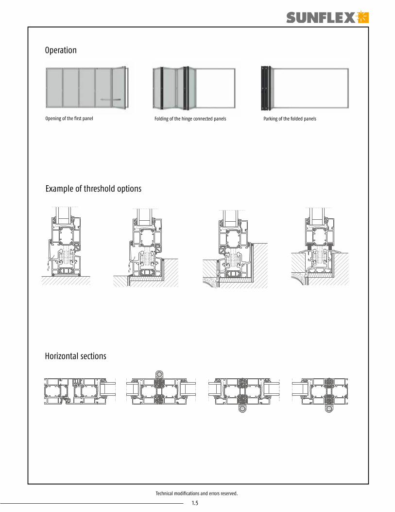
No. 13/07-A254-Z2
The therma transmittance of frames Uf and linear thermal transmittance calculated according to DIN EN ISO 10077-2 : 2012-06 (German version EN ISO 10077-2 : 2012), as well as thermal transmittance Uw calculated according to DIN EN ISO 10077-1 : 2010-05
Uw 1,6
1286-001-10
Determination of the airborn sound insulation acc. to DIN EN ISO 10140-3 test stand.
- Sound reduction index Rw in dB / 36 dB

1.12
Technical modifications and errors reserved.

1.13
Technical modifications and errors reserved.
Technical Information
Profile system Glass folding partition in non thermally insulated aluminum profiles Bottom-supported construction Construction profile depth: 2 3/16“ (55 mm) Recessed or surface-mounted floor track Opens inwards or outwards Opens by sliding to one side or both sides Roller track and guide tracks are flush to system faces Design allows for height differences and expansion
Hardware All fittings hidden within profiles Low-maintenance, non-corroding and failsafe hardware components Panels lock via rods that engage in floor and ceiling tracks and/or via sliding doors that engage in the frames or with
the neighboring panels Locking and unlocking via actuating levers with anti-intruder catches Optionally fitted with different lock types Hinges feature pivot pins that cannot be knocked out (anti-intruder feature) A pivoting panel can be securely clamped to the adjacent panel using snap latches
Runner system Simple adjustment due to a height-adjustable runner assembly system Runner assemblies are situated above water drainage collection area Low-noise, hard-wearing, heat and cold resistant running rollers
Sealing and ventilation Rain and wind proofing ensured by EPDM seals at two sealing levels
Glazing A glazing configuration of 1/4“ to 1 1/2“ (6 mm to 38 mm) possible Glazing can be replaced without difficulty

1.14
Technical modifications and errors reserved.
Ref. Section Description Page
-- SF50-000 Vertical-Section, glazing beads designs (softline + square - edge) 1.15
F SF50-001 Vertical-Section, connection bottom track / inwards folding 1.15
F SF50-003 Vertical-Section, connection bottom track / outwards folding 1.15
F SF50-005 Vertical-Section, connection flush bottom track 1.15
A SF50-002 Vertical-Section, connection top track / inwards folding 1.16
A SF50-004 Vertical-Section, connection top track / outwards folding 1.16
F SF50-007 Vertical-Section, strengthening profile for balustrade / inwards folding 1.16
A SF50-008 Vertical-Section, strengthening profile for overhead light / inwards folding 1.16
A SF50-009 Vertical-Section, connection top track overhead light / inwards folding 1.17
B SF50-101 Horizontal-Section, side jamb - panel closing section / inwards folding 1.17
B SF50-102 Horizontal-Section, side jamb - panel closing section / outwards folding 1.17
D SF50-103 Horizontal-Section, panel - panel / hinge outwards 1.17
C SF50-104 Horizontal-Section, panel - panel / hinge inwards 1.18
E SF50-105 Horizontal-Section, vertical post - panel / hinge inwards 1.18
E SF50-106 Horizontal-Section, vertical post - panel / hinge outwards 1.18
D SF50-107 Horizontal-Section, midrail 1.18
G SF50-108 Horizontal-Section, panel - panel closing section 1.19
E SF50-109 Horizontal-Section, frame extension 35 mm 1.19
E SF50-110 Horizontal-Section, frame extension 70 mm 1.19
E SF50-111 Horizontal-Section, 90°- connection profile 1.19
E SF50-112 Horizontal-Section, 135°- connection profile 1.20
D SF50-113 Horizontal-Section, sliding post / hinge outwards 1.20
D SF50-121 Horizontal-Section, sliding post / hinge inwards 1.20
D SF50-114 Horizontal-Section, sliding post incl. strengthening / hinge outwards 1.20
D SF50-115 Horizontal-Section, closing section - sliding post (e.g. 1L/2R) / outwards folding 1.21
D SF50-116 Horizontal-Section, closing section - sliding post (e.g. 1L/2R) / inwards folding 1.21
C SF50-117 Horizontal-Section, side jamb - panel closing section incl. sliding post (e.g. 2R) / o. f. 1.21
C SF50-118 Horizontal-Section, side jamb - panel closing section incl. sliding post (e.g. 2R) / i. f. 1.21
-- SF50-119 Horizontal-Section, profil section - sliding post (e.g. 2L/2R) / outwards folding 1.22
-- SF50-120 Horizontal-Section, profil section - sliding post (e.g. 2L/2R) / inwards folding 1.22
Details at uneven panel partitioning in one direction Details at even and uneven panel partitioning in two directions

1.15
Technical modifications and errors reserved.
Description: Description:
Description: Description:
System:
Detail-No.:
System:
Detail-No.:
System:
Detail-No.:
System:
Detail-No.:
Vertical-Section,glazing beads designs(softline + square - edge)
SF50
SF50-000
OUTS
IDE
INSI
DE
Vertical-Section,connection bottom track / inwards folding
SF50
SF50-001
OUTS
IDE
INSI
DE
Vertical-Section,connection bottom track / outwards folding
SF50
SF50-003
OUTS
IDE
INSI
DE
Vertical-Section,connection flush bottom track
SF50
SF50-005
OUTS
IDE
INSI
DE

1.16
Technical modifications and errors reserved.
Description: Description:
Description: Description:
System:
Detail-No.:
System:
Detail-No.:
System:
Detail-No.:
System:
Detail-No.:
Vertical-Section,connection top track / inwards folding
SF50
SF50-002
OUTS
IDE
INSI
DE
Vertical-Section,connection top track / outwards folding
SF50
SF50-004
OUTS
IDE
INSI
DE
Vertical-Section,strengthening profile forbalustrade / inwards folding
SF50
SF50-007
OUTS
IDE
INSI
DE
Vertical-Section,strengthening profile for over-head light / inwards folding
SF50
SF50-008
OUTS
IDE
INSI
DE

1.17
Technical modifications and errors reserved.
Description: Description:
Description: Description:
System:
Detail-No.:
System:
Detail-No.:
System:
Detail-No.:
System:
Detail-No.:
Vertical-Section,connection top track overhead light / inwards folding
SF50
SF50-009
OUTS
IDE
INSI
DE
Horizontal-Section,side jamb - panel closing section / inwards folding
SF50
SF50-101
Horizontal-Section,side jamb - panel closing section / outwards folding
SF50
SF50-102
Horizontal-Section,panel - panel / hinge outwards
SF50
SF50-103
OUTSIDEOUTSIDE
OUTSIDE
INSIDEINSIDE
INSIDE

1.18
Technical modifications and errors reserved.
Description: Description:
Description: Description:
System:
Detail-No.:
System:
Detail-No.:
System:
Detail-No.:
System:
Detail-No.:
Horizontal-Section,panel - panel / hinge inwards
SF50
SF50-104
Horizontal-Section,vertical post - panel / hinge inwards
SF50
SF50-105
Horizontal-Section,vertical post - panel / hinge outwards
Horizontal-Section,midrail
SF50 SF50
SF50-106 SF50-107
OUTSIDE
OUTSIDE OUTSIDE
INSIDE
INSIDE INSIDE
OUTSIDE
INSIDE

1.19
Technical modifications and errors reserved.
Description: Description:
Description: Description:
System:
Detail-No.:
System:
Detail-No.:
System:
Detail-No.:
System:
Detail-No.:
Horizontal-Section,panel - panel closing section
SF50
SF50-108
Horizontal-Section,frame extension 35 mm
SF50
SF50-109
Horizontal-Section,frame extension 70 mm
Horizontal-Section,90°- connection profile
SF50 SF50
SF50-110 SF50-111
OUTSIDE
OUTSIDE OUTSIDE
INSIDE
INSIDE INSIDE
OUTSIDE
INSIDE

1.20
Technical modifications and errors reserved.
Description: Description:
Description: Description:
System:
Detail-No.:
System:
Detail-No.:
System:
Detail-No.:
System:
Detail-No.:
Horizontal-Section,135°- connection profile
SF50
SF50-112
Horizontal-Section,sliding post / hinge outwards
SF50
SF50-113
Horizontal-Section,sliding post / hinge inwards
Horizontal-Section,sliding post incl. strengthening / hinge outwards
SF50 SF50
SF50-121 SF50-114
OUTSIDE
OUTSIDE OUTSIDE
INSIDE
INSIDE INSIDE
OUTSIDE
INSIDE

1.21
Technical modifications and errors reserved.
Description: Description:
Description: Description:
System:
Detail-No.:
System:
Detail-No.:
System:
Detail-No.:
System:
Detail-No.:
Horizontal-Section,closing section - sliding post (e.g. 1L/2R) / outwards folding
SF50
SF50-115
Horizontal-Section,closing section - sliding post (e.g. 1L/2R) / inwards folding
SF50
SF50-116
Horizontal-Section,side jamb - panel closing section incl. sliding post (e.g. 2R) / o. f.
Horizontal-Section,side jamb - panel closing section incl. sliding post (e.g. 2R) / i. f.
SF50 SF50
SF50-117 SF50-118
OUTSIDE
OUTSIDE OUTSIDE
INSIDE
INSIDE INSIDE
OUTSIDE
INSIDE

1.22
Technical modifications and errors reserved.
Description: Description:
Description: Description:
System:
Detail-No.:
System:
Detail-No.:
System:
Detail-No.:
System:
Detail-No.:
Horizontal-Section,profil section - sliding post (e.g. 2L/2R) / outwards folding
SF50
SF50-119
Horizontal-Section,profil section - sliding post (e.g. 2L/2R) / inwards folding
SF50
SF50-120
OUTSIDE
INSIDE
OUTSIDE
INSIDE

2.1
Technical modifications and errors reserved.
W
W
H H
W
W
H H
W
W
H H
Measurement
It is important to measure at multiple points for both height and width making sure to capture the shortest height and width.


3.1
Technical modifications and errors reserved.
Assembly instructions
Tools required:
Scope of delivery: A. Top railB. Vertical profileC. Floor railD. Hinged panel, sliding panelAccessories pack
Safety instructions: These assembly instructions are specifically designed for the use of authorized specialists. Observation and implementation of therelevant safety regulations are a prerequisite.
Symbols used:
D
C
A
B
B
Caution Note
SF 50 / SF 50cSF 55 / SF 55c
SF 75 / SF 75c / SF 75H

3.2
Technical modifications and errors reserved.
ContentDescription
1. Assembly of door frame
2. Installation of door frame
3. Fitting of panel
4. Adjustment
5. External foam sealing
6. Fitting of accessories
SF 50 (c+i) sliding post with odd number of panels
SF 50 (c+i) sliding post with even number of panels
Assembly of the panel notch
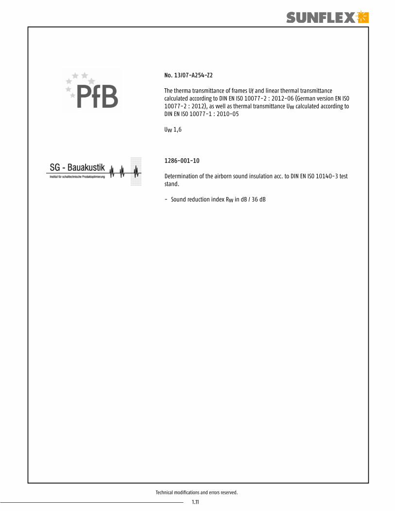
Assembly only for SF 75H
Page
3.3
3.4
3.5, 3.6
3.6
3.7
3.7
3.8
3.9
3.10
3.11 - 3.13
© Copyright | SUNFLEX Aluminiumsysteme GmbH | Im Ruttenberge 12 | D-57482 Wenden | Issue: 04/2015
Importent:
After successful assembly the fitter must give instructions to the customer in order to avoid incorrect operation.

3.3
Technical modifications and errors reserved.
1. Assembly of the door frame
• Unpacking the supplied frame profile.• Sorting of the frame profile - The floor rail has external water drain slots on the internal opening element. - Top rail has no water drain slots. - The vertical profiles are marked “right‘ and “left‘ (viewed from the inside) on the wall side.• The vertical profiles must be pushed flush into the guide rail.• Cutout (Adjustment opening) is directed only at the bottom rail, on the hinge side.
Assembly shoe
Assembly shoe
Assembly shoe
Floor/Guide profile
Adjustment opening
Assembly shoe
Vert
ical
fram
e (b
and
side)
Vert
ical
fram
e (lo
ckin
g po
st)
Top rail Carriage bracket1 oben
top
untenbottom
LinksLeft
untenbottom
obentop
RechtsRight
untenbottom
obentop
Before assembling please ensure the guide shoes areinserted.

3.4
Technical modifications and errors reserved.
2a
2. Installation of the door frame
• Determination of fixing points (pic 2a). - Approx 4-7 inches from external frame cover, distribute remainder at an interval of approx 12-15 inches. - The vertical assembly points are distri- buted evenly along the height.• Support floor rail every 12 inches.• Rectangle the alignment and wedging of the frame.• Screw tight all profiles except for the locking posts.
• Place the frame in the building opening.• Arrange door frame vertically. Check for parallel fitting!
2

3.5
Technical modifications and errors reserved.
3. Fitting the panel
4 • Fit the first panel and secure with the hinge bolts provided (the panels are numbered at the top and bottom.
Fixin
g di
rect
ion
Fixing direction
Fixin
g di
rect
ion
Panel 1
Asse
mbl
y po
sitio
n
Panel 2 Panel 3, 4, ...
Assembly shoe
Carriage fittingBearing bolt
Assembly shoe
Assembly shoe
Floor/guide profile
Assembly shoe
Vert
ical
fram
e (b
and
side)
Vert
ical
fram
e (lo
ckin
g po
st)
Carriage fittingBearing bolt
Top rail Carriage bracket
Asse
mbl
y po
sitio
n
3
CC
1
5
2
• Place the second panel with the bearing bolts in the carriage (C) and fit to the first panel.• The upper bearing bolt must be pressed fully down.
1 = Lock using M5 grub screw Allen key 2.5 mm2 = Height adjustment using M10 grub screw Allen key 5 mm
Clearance panel to floor rail approx. 3/8 inch.
Position of handle:If the locking bar on the panel profile is firmly pushed in flush the handle always points upwards.

3.6
Technical modifications and errors reserved.
A
B
7
16
CD
22
• Now screw the upper bearing bolt into the guide carriage (D) until the bolt is flush with the bracket.• Close the first pair of panels and repeat the first four steps of point 3 according to the number of panels and panel arrangement.
• All hinge bolts should now be secured with the supplied grub screws (B). The corresponding holes are in the integral hinge section. They are clearly visible when an element is open.
Band side
Locking post
8• The closure clearance is set by sliding the door frame locking post. When the locking post shows a constant (approx 3/8 inch wide) closure clearance with the panel, this can then be wedged and screwed in.• For panel distribution left and right the closure is set by re-wedging of the band side vertical post.• The adjustment bearing bolts permit the panel height within the pic- ture frame to be adjusted. This can be easily adjusted in the moun- ted state with unlocked panels.
4. Adjustment
1 = Lock using M5 grub screw Allen key 2.5 mm2 = Height adjustment using M10 grub screw Allen key 5 mm

3.7
Technical modifications and errors reserved.
• Fit the supplied panel clips to the panel as shown in the illustration.• To release, move panel packet from parking position. The trigger lock released automatically when closing.
The illustration shows the stop strip (swivel panel).
• Diagram shows view from above of the SF clip.
6. Accessory installation
Turn panel
10 11
9
The door frame corners must be fully sealed from the inside.
5. Foam sealant
Only by uneven number of panels (3, 5, 7 ...)

3.8
Technical modifications and errors reserved.
SF 50 (c+i) sliding post with odd number of panels
AA
BB
2 3 4
Fixin
g di
rect
ion
Fixing direction
Fixin
g di
rect
ion
Panel 1
Asse
mbl
y po
sitio
n
Panel 2 Panel3, 5, ...
Assembly shoe
Assembly shoe
Assembly shoe
Floor/guide profile
Assembly shoe
Vert
ical
fram
e (b
and
side)
Vert
ical
fram
e (lo
ckin
g po
st)
Support for the guide carriageSupport for the guide carriage
Sliding post
Top rail
Carriage fittingCarriage fitting
Asse
mbl
y po
sitio
n
1
5• Insert the sliding post in a slightly angled position first into the carriages (bottom rail, picture 3) and only afterwards into the carriage brackets (top rail).
• Picture 4 shows sliding post positioned in bottom rail.
• Picture 5 shows sliding post positioned in top rail.
• Picture 2: Bolt (A) carriage bracket Bolt (B) carriage

3.9
Technical modifications and errors reserved.
A
B
2
Assembly shoe
Assembly shoe
Assembly shoe
Assembly shoe
Vert
ical
fram
e (lo
ckin
g po
st)
Support for the guide carriage
Sliding post connection bolt
Carriage fitting
Fixin
g di
rect
ion
Fixing directionPanel 1
Asse
mbl
y po
sitio
n
Panel 2, 4, ...
Sliding post connection bolt
Sliding post
1
5
3 4
SF 50 (c+i) sliding post with even number of panels
• Insert the sliding post in a slightly angled position first into the carriages (bottom rail, picture 3) and only afterwards into the carriage brackets (top rail).
• Picture 4 shows sliding post positioned in bottom rail.
• Picture 5 shows sliding post positioned in top rail.
• Picture 2: Bolt (A) carriage bracket Bolt (B) carriage

3.10
Technical modifications and errors reserved.
Position 559939SF50, SF55
Position 759922SF75, SF75H
1
Assembly of the panel notch
559939(SF50, SF 55)
759922(SF75, SF 75H)
2
4
3
Only by uneven number of panels (3, 5, 7 ...)
3.11
Technical modifications and errors reserved.
1
Assembly only for SF 75H
2
4
3
5

3.12
Technical modifications and errors reserved.
8
10
6
9
11
7

3.13
Technical modifications and errors reserved.
14
12 13
Foaming and sealing
After acceptance by the customer, the joint formed between blind frame and building structure has to be foamed and/or sealed.
The corners of the blind frame are to be sealed from the inside against the penetration of water into the structure by means ofa sealing material.
On site, the glass has to be sealed from the inside and outside towards the panel frame.


4.1
Technical modifications and errors reserved.
Safety instructions
• Risk of injury by trapping of body parts.
• Risk of injury and material damage by pressing the panel against the opening edge.
• Risk of injury and material damage by placing obstacles between panel and frame.
• Risk of injury and material damage due to additional load at the panel.
• Risk of injury by wind action.
• Risk of injury by falling through open windows.

4.2
Technical modifications and errors reserved.
Operation
Opening of the first panel
Folding of the hinge connected panels
Parking of the folded panels

4.3
Technical modifications and errors reserved.
Maintenance and servicing instructions
General
External building parts are not only subject to the weather, but also increased stress caused by smoke, industrial fumes and aggressive airborne dust. In conjunction with rain and dew, deposits of these substances may affect the surface and change the appearance. External parts must therefore be cleaned (at least twice annually or more frequently depending on the degree of contamination) to avoid possible settling of deposits. The sooner you remove dirt from the surface, the easier it is to clean. Observe the safety instructions and instructions for use of the respective servicing and cleaning products. When cleaning do not use a material with an unknown composition. If you are not certain about the effect of the cleaner , then test it first by cleaning a visually unimportant, non-exposed portion of the component.
Fittings
All fittings must be regularly checked for tightness and wear. Attachment screws must be tightened and defective parts replaced as required. In addition, at least once a year, all moving and sliding fittings must be lightly greased with fitting grease. Only servicing and cleaning agents that do not affect the corrosion protection of fittings should be used.
Glass surfaces
Dirty glass surfaces can be cleaned using water and a sponge or cloth, etc. Commercially available non-abrasive glass cleaners (such as Ajax, Pril, etc.) can be added to the water. Stubborn stains such as paint or tar splashes should be removed with me-thylated spirits or white spirit.
Caution!Do not use alkaline caustic solutions, acids, and fluoride-containing detergents to clean glass surfaces.
Caution!A suitable protective film should be used to protect the glass surface against mortar spattering, cement slurry, sparks or weld sputtering from partitioning screens and stone-facade acidic-cleaner..
Seals
All seals must be cleaned and lubricated at least once a year to ensure good functioning. For this purpose we recommend the use of a seal care product. The care product maintains the suppleness of the seal, thus preventing premature brittleness. Ensure that the seals are not damaged and do not come into contact with solvent materials.
Aluminium surfaces
Anodizing and powder coating is a highly durable and decorative finishing for aluminium components. To maintain the deco-rative appearance of such components for decades, the surfaces need to be regularly maintained by means of cleaning twice a year.
Cleaning anodized surfaces
Cleaning of the surfaces must not take place in direct sunlight, the surface temperature must not exceed 25°C. Use only neutral pH cleaners such as normally diluted washing up liquid. Abrasive or scouring materials must not be used to clean heavily soiled, anodized surfaces - cleaning pastes are available.

4.4
Technical modifications and errors reserved.
Cleaning powder-coated surfaces
In the same way as for anodized elements, cleaning must be carried out whilst cold (maximum of 25 °C surface temperature). In this case also, use only pH-neutral material. Solvent-based cleaners attack the surface of the powder coating and, like scouring or abrasive cleaners, should not be used. To remove stubborn fat and greasy dirt we recommend aroma-free methylated spirits. This must only be applied for a short time and then rinsed off with clean water. In addition, we recommend treatment with car wax to leave a water-repellent film. Check on a non-exposed area whether the material used has an adverse effect on the shine.
Wood surfaces on wood/aluminium elements
For the cleaning of internal wood surfaces it is best to use mild detergent such as dilute detergent and soap suds. Since the internal wood surfaces are not subject to wear and weathering by rain and sun light, painting is not required. Avoid abrasive, corrosive and solvent-based cleaners. Use only soft cloths to avoid scratching the paint surface. Window cleaners contain small traces of alcohol and ammonium chloride. These materials are very suitable for cleaning the glass as well as the wood-frame sections. After cleaning, dry the wood profiles with a dry, soft cloth, because extended exposure to alcohol can soften the paint surface.
SUNFLEX Aluminiumsysteme GmbHIm Ruttenberge 12D-57482 Wenden-GerlingenTel.: +49 (0) 2762 / 9253-0Fax: +49 (0) 2762 / [email protected]

5.1
Technical modifications and errors reserved.
Limited Warranty
Seller warrants that the Products will, when delivered, substantially conform to the respective written Product descriptionfurnished to Purchaser, and all Products to be free from defects in material and workmanship within twenty four (24) monthsperiod from the date of manufacture and will perform in accordance with SUNFLEX operating instructions if properly installed,used and serviced. Should a Product(s) become defective within such period, Purchaser at its cost shall submit its claim and thedefective Product to SUNFLEX and the sales receipt stating the defects and the circumstances under which the defect occurred inwhich case SUNFLEX will examine, and upon establishing Purchaser’s validity of claim, at its sole discretion repair the Product(s), exchange the Product(s), or refund the purchase price, which shall fully satisfy and discharge any and all warranty claims. Warranty related inquiries should be addressed to the following address: SUNFLEX WALL SYSTEMS LP c/o Warranty Service, Naples, Florida. This warranty extends only to Product(s) installed as specified for the respective Product(s) and does not extend to any product(s) (i) which has been used inconsistent with its intended use, (ii) has not been properly installed by a qualified licensed technician experienced in the installation of the Product(s), (iii) which was modified or repaired by anyone other than SUNFLEX personnel or authorized service representative, (iv) damaged because of misuse, neglect or improper installation or service. No warranty of fitness for a particular purpose is made. In addition, the foregoing warranty shall not apply to any parts or compo-nents not manufactured by Seller.
THE WARRANTIES SET FORTH HEREIN ABOVE ARE IN LIEU OF ALL OTHER WARRANTIES EXPRESS OR IMPLIED. THE SALE IS MADE ON THE EXPRESS UNDERSTANDING THAT HERE IS NO IMPLIED WARRANTY THAT THE PRODUCTS SHALL BE FIT FOR ANY PARTICULAR P URPOSE. THE PURCHASER ACKNOWLEDGES THAT PURCHASER IS NOT RELYING ON SELLER’S SKILLS OR JUDGMENT TO SELECT OR FURNISH PRODUCTS SUITABLE FOR ANY PARTICULAR PURPOSE OR JOB OR TO DETERMINE FEASIBILITY OF THE PRODUCTS FOR ANY PARTICULAR PURPOSE. THE PURCHASER ACKNOWLEDGES THAT THERE ARE NO WARRANTIES WHICH EXTEND BEYOND THE DESCRIPTION HEREIN. IN NO EVENT SHALL SUNFLEX BE LIABLE FOR CONSEQUENTIAL, INCIDENTAL, OR SPECIAL DAMAGES, AND DAMAGES ARISING OUT OF THE PURCHASE, UNLOADING, HANDLING, AND USE OF ANY PRODUCTS, ALL OF WHICH ARE WAIVED BY PURCHASER AND IN ANY EVENT, DAMAGES HEREUNDER SHALL BE LIMITED TO A MAXIMUM OF THE PURCHASE PRICE. THIS WARRANTY GIVES THE CONSUMER SPECIFIC LEG ALL RIGHTS AND THE CONSUMER MAY ALSO HAVE OTHER RIGHTS WHICH MAY VARY FROM STATE TO STATE.
The Purchaser shall inspect and accept or reject acceptance of the Products immediately upon the arrival and shall, within five (5)days after the arrival, give written notice to SUNFLEX of any claim that the Product(s) do not conform with the terms of the order.If the Purchaser shall fail to give such notice, the Product(s) shall be deemed to have been accepted and the Purchaser shall pay for the products in accordance with the terms of the order. The purchaser expressly waives any rights the Purchaser may have torevoke acceptance after such five (5) day period.

5.2
Technical modifications and errors reserved.

6.1
Technical modifications and errors reserved.
TERMS OF SALE
1. Purchase of Products
A Except to the extent otherwise agreed upon in writing, the terms set forth herein shall govern the sale and delivery of the wall systems described on the reverse side hereof (“Products‘) by Sunflex Wall Systems LP (“Seller‘) and purchased by the purchaser named on the reverse side hereof (“Purchaser‘).
B All dealings between the parties shall be in writing and no order of Purchaser shall be binding on Seller until approved in writing by Seller.
C Prices of Products are subject to change without notice, and all references in sales brochures, technical data sheets and offers as to size, weight, and other details of the Products are approximate only. No such term shall be binding on Seller unless expressly incorporated in a purchase order which is approved and accepted by Seller in accordance with the terms hereof.
D Except as provided in subsection (e) of this Section 1, a purchase contract hereunder shall become effective upon the mailing of a written acceptance of Purchaser’s order by Seller.
E If the terms stated in Purchaser’s order are not acceptable to Seller, Seller may amend, delete or alter such terms and submit a counter-offer incorporating such amendments, deletions or alterations to Purchaser, it being understood and agreed that such counter offer shall be deemed accepted by Purchaser and shall become binding on the parties if and in case Seller does not receive notice to the contrary from Purchaser within 3 (three) days after Seller has sent such counter-offer to Purchaser.
F Purchaser acknowledges that Seller’s acceptance of any purchase order is dependent on Seller’s prior approval of Purchaser’s credit. Purchaser agrees that Seller may demand assurances of Purchaser’s ability to pay by requesting such trade or banking references or such other information as deemed adequate by Seller.
2. Delivery
A Unless expressly agreed upon in writing to the contrary, the terms of delivery are Delivery Duty Paid (DDP) to Purchaser’s receiving dock. Seller will use commercially reasonable efforts to make the products available for pick up by Purchaser or delivery within a reasonable time after acceptance of an order from Purchaser.
B Purchaser bears the risk of loss or destruction of the Products upon and after the first to occur of (i) signed receipt and acceptance of delivery of Products by Purchaser or his agent, (ii) pick-up or acceptance of the Products by Purchaser or its common carrier at Seller’s place of business or (iii) the 14th (fourteenth) day after notification from Seller that the Products are ready for pick-up or delivery from the seller’s place of business. In the event the Purchaser requests a delay in pick-up or delivery, Purchaser assumes all risk of loss, damage and/or destruction of the Products from the date the Products are ready to be picked up or delivered.
C Purchaser agrees that it will pick up at Seller’s place of business or agree for Seller to ship Products purchased for delivery within 14 (fourteen) days after written notification from Seller that Products are ready to be received by Purchaser. If Purchaser does not pick up or agree to have Seller ship products within 14 (fourteen) days after notification from Seller and/or Seller is required to store the Products due to any delay caused by Purchaser, Purchaser shall reimburse Seller for reasonable storage charges.

6.2
Technical modifications and errors reserved.
D Seller reserves the right to make the Products available for pick-up and delivery in installments provided that such installments shall not be less than one product unit, unless otherwise expressly stipulated to the contrary in a written document signed by Seller. Delay in delivery of any installment shall not relieve Purchaser of its obligation to accept remaining deliveries.
E If Purchaser should request any modification of the order after Seller’s acceptance, Seller shall have the right to extend the delivery time period as reasonably needed to complete Purchaser’s change order.
3. Force Majeure Notwithstanding anything to the contrary, Seller shall not be liable for any delay or failure to perform hereunder when such failure or delay is, directly or indirectly, caused by, or in any manner arises from fire, floods, accidents, civil unrest, acts of God, war, terrorism, governmental interference or embargoes, strikes, labor difficulties, shortage of labor, fuel, power, materials, or supplies, breakage of machinery or apparatus, transportation delays, or any other cause or causes (whether or not similar in nature to any of those hereinbefore specified) beyond its control.
4. Warranties and Claims
A Seller warrants that the Products when delivered shall comply with standards and limitations set forth in the Limited Warranty.
B Purchaser shall within five (5) working days after its receipt of the Products, and in any event no later than thirty (30) days from the shipping date, give written notice to Seller of any claim that the Products do not conform with the terms of the order or have material defects which a casual inspection would disclose. If Purchaser fails to give such notice, the Products shall be deemed to conform to the terms of the order, and Purchaser shall be deemed to have accepted and shall pay for the Products in accordance with the terms of this order. Purchaser expressly waives any right Purchaser may have to revoke acceptance or claim a breach of warranty with respect to such obvious or material defects, a casual inspection should have disclosed after such five-day period.
EXCEPT AS SET FORTH EXPRESSLY IN SELLER.S STANDARD WRITTEN WARRANTY WITH RESPECT TO THOSE ITEMS MANUFACTURED BY SELLER, SELLER MAKES NO REPRESENTATIONS OR WARRANTIES OF ANY KIND, EXPRESS OR IMPLIED, WRITTEN OR ORAL, WITH RESPECT TO THE PRODUCTS, INCLUDING, WITHOUT LIMITATION, ITS MERCHANTABILITY OR FITNESS FOR A PARTICULAR PURPOSE.
PURCHASER ACKNOWLEDGES THAT PURCHASER IS NOT RELYING ON SELLER.S SKILL OR JUDGMENT TO SELECT OR FURNISH PRODUCTS SUITABLE FOR ANY PARTICULAR PURPOSE OR JOB, OR TO DETERMINE THE FEASIBILITY OF THE PRODUCTS FOR ANY PARTICULAR APPLI-CATIONS. PURCHASER ACKNOWLEDGES THAT THERE ARE NO WARRANTIES WHICH EXTEND BEYOND THE DESCRIPTION HEREIN. NEITHER SELLER NOR ANY OF ITS AFFILIATES SHALL BE LIABLE FOR, AND PURCHASER WAIVES ANY CLAIM AGAINST SELLER AND ITS AFFILIATES FOR, MULTIPLE, INCIDENTAL, SPECIAL OR CONSEQUENTIAL DAMAGES, INCLUDING, BUT NOT LIMITED TO, DAMAGE OR LOSS OF OTHER PROPERTY OR PRODUCTS, LOSS OF PROFITS OR REVENUE, LOSS OF USE OF MACHINERY OR PARTS THEREOF, INABILITY TO PERFORM SPECIFIC PROJECTS, COST OF CAPITAL, INJURIES TO OR DEATH OF PERSONS OR DAMAGE TO PROPERTY OR CLAIMS RESULTING FROM CONTRACTS AND/OR AGREEMENTS BETWEEN PURCHASER, ITS CUSTOMERS AND/OR SUPPLIERS, IN EACH CASE WHICH IN ANY WAY RELATE TO THE PURCHASE OF PRODUCTS BY PURCHASER OR THE USE OF THE PRODUCTS.

6.3
Technical modifications and errors reserved.
5. Prices
A All prices quoted by Seller are in U.S. funds and shall be on a net basis DDP (Delivered Duty Paid) to Purchaser’s receiving dock.
B All prices quoted by Seller are subject to adjustment due to Purchaser’s change orders, if any.
C Unless otherwise expressly agreed upon in writing, the price quoted includes the cost of packaging, special containers, crating, palletizing, applicable taxes and duties, shipping, insurance or any other cost to provide Products to Purchaser.
6. Payment
A Unless otherwise expressly agreed upon in writing, payment shall be made in full according to the terms specified on page 1 hereof. Purchaser shall not withhold or reduce payments on account of complaints, claims, or counterclaims not acknowledged and accepted by Seller.
7. Default
A Purchaser shall be in default (hereinafter .Default.) under this Agreement and Seller may terminate this Agreement and exercise all other remedies in law or in equity if Purchaser: (i) fails to make payment hereunder to Seller when due; or (ii) breaches any other term, provision or condition contained in this Agreement; or (iii) is declared to be in default under any other agreement between Purchaser and Seller, and if in any of the foregoing cases set out in (i), (ii) or (iii), Purchaser fails to cure any said breach or default within 5 (five) days following written notice thereof from Seller.
B Upon the occurrence of a Default, Seller may elect to exercise any one or more of the following options:
i. Seller may hold the Products until such time as Purchaser has paid the respective purchase price and any expenses (including finance charges, returned check fees and interest determined at a rate equal to the lower of eighteen percent (18%) per annum or the maximum rate permitted by applicable law incurred by Seller as a consequence of such default. ii. Seller may sell the Products to a third party and require Purchaser to reimburse Seller for any losses, or expenses associated therewith. iii. Seller may require payment in cash prior to delivery of any Products hereunder. iv. Seller may withhold any Products not delivered to Purchaser at the time of the default. v. Seller may terminate this Agreement. vi. Seller may exercise all other rights hereunder and may seek all other remedies available to it in law or in equity.
C Purchaser agrees that, in the event any legal action should be deemed necessary by Seller to recover any sums due hereunder or under any promissory note, trade acceptance, or invoice, or, if applicable, to recover possession of the Products, as defined hereinabove, or any proceeds from the sales thereof, there shall be added to the sums due from Purchaser to Seller the costs of collection, including reasonable attorney’s fees.
D When reasonable grounds for insecurity arise with respect to Purchaser’s performance, Seller may in writing demand assurance of due performance and until it receives such assurance may suspend any performance for which it has not already received payment.

6.4
Technical modifications and errors reserved.
8. Protection of Trade Secrets and Confidential Information The parties hereto agree that
A Except as provided for in subsection (b) of this Section, Purchaser shall not disclose any Trade Secrets or Confidential Information of the other party to any individual or entity not a party to this Agreement.
B Purchaser may make available Trade Secrets or Confidential Information to its qualified employees, as defined herein after, to the extent that such information must be disclosed to such qualified employees to apply the Trade Secrets or Confidential Information to its intended use. A “qualified employee‘ shall mean any individual employed by or affiliated with Purchaser who is bound by a valid and fully enforceable confidentiality agreement which contains confidentiality obligations substantially similar to the confidentiality obligations stated herein, prior to disclosure of the Trade Secrets and Confidential Information to such employee. C For purposes of this Agreement the following terms shall have the meanings set forth below: i. The term ‘Trade Secrets‘ shall mean and include any and all designs, plans, processes, tools, mechanisms, programs or compounds known to only Seller, or to those of its clients and employees to whom they must be confided in order to be applied to the uses intended, some or all of which may arise to the level of being patentable or subject to copyrights, all as further defined under the laws of the State of Florida. ii. The term “Confidential Information‘ shall mean and include information not rising to the level of Trade Secret and not generally known to or by a business in competition with the Seller or otherwise publicly disseminated by the protected party hereto, the disclosure of which may be beneficial to a competing business or detrimental to Seller.
9. Arbitration
Any controversy or claim arising out of or relating to this Agreement, or the breach hereof, shall be submitted to and be finally resolved by arbitration, to be conducted by the American Arbitration Association (.AAA.), with such arbitration to be held in Atlanta, Georgia in accordance with the AAA.s Commercial Arbitration Rules then in effect. Each party hereby irrevocably agrees that service of process, summons, notices, as other communications related to the arbitration procedures shall be deemed served and accepted by the other party five (5) working days after having been mailed by first class registered mail, return receipt requested, postage prepaid, to the other party, or if actually received by the other party. The arbitration shall be conducted by one arbitrator, as selected by the AAA. Any award or decision rendered in such arbitration shall be final and binding on both parties, and judgment may be entered thereon in any court of competent jurisdiction if necessary. Except as may be provided to the contrary herein, each party hereto shall pay any and all expenses incurred by such party in connection with such arbitration proceeding, unless otherwise determined by the arbitrator.
10. Miscellaneous
A Purchaser may not assign this contract without the express prior written consent of Seller. B Except as otherwise expressly provided in Section 1(e) hereof or in a written document, signed by Seller and Purchaser, this document and attachments and exhibits thereto constitute the entire agreement between Seller and Purchaser with respect to the subject matter herein contained and all prior agreements and communications between Seller and Purchaser, whether oral or written, are superseded by this Agreement.

6.5
Technical modifications and errors reserved.
C No modification, limitation, waiver or discharge of this Agreement or of any of its terms shall bind Seller unless in writing and signed by a duly authorized employee of Seller. The failure of Seller to insist, in one or more instances, on performance by Purchaser in strict compliance with the terms and conditions hereof shall not be deemed a waiver or relinquishment of any right granted hereunder with respect to any succeeding breach of the same or other provision hereof. D All notices required hereunder shall be in writing and sent by first class mail or by telefax or written confirmation to such addresses as stated on the reverse side hereof.
E This Agreement shall be governed by, and construed, interpreted and enforced under the laws of the State of Florida without giving effect to the conflict of laws principles.
F In connection with any litigation, including appellate proceedings, arising out of or pertaining to any of the contractual relationships between Seller and Purchaser or the breach thereof, as contemplated herein, all costs and expenses, including reasonable attorneys fees, shall be borne by the losing party or, as the case may be, shall be prorated to properly reflect any partial losing or prevailing of the parties to such litigation.
G In case any conditions of this Agreement should be or become unenforceable under applicable law, the remaining provisions, stipulations and conditions of this Agreement shall not be affected thereby.

DISTRIBUTOR:New York, New Jersey, and greater Philadelphia area
ModernfoldStyles, Inc.15 Empire BoulevardSouth Hackensack, NJ 07606Main: 201.329.6226New York: 212.684.4210Long Island: 516.692.4100
802 King AvenueCherry Hill, NJ 08002Southern NJ / PA: 856.665.1488
www.modernfoldstyles.com


![Burglar Alarm-Final Report[1]](https://static.fdocuments.net/doc/165x107/54771888b4af9f7b108b4621/burglar-alarm-final-report1.jpg)