System proS Enclosed Starters - ABB Group · 7 System proS Single Phase Starters, Non-Combination1...
38
System proS Enclosed Starters
Transcript of System proS Enclosed Starters - ABB Group · 7 System proS Single Phase Starters, Non-Combination1...

System proSEnclosed Starters
1
System proSEnclosed Products
System proS easy as ABB ................................................................................2-3Technical Specifications ....................................................................................4-5Catalog Number Explanation................................................................................ 6Non-Combination Starters, 1 phase ..................................................................... 7Combination Starters, 1 phase ............................................................................. 8Non-Combination Starters, 3 phase ..................................................................... 9Combination Starters, 3 phase ......................................................................10-12Non-Combination Starters 2S-2W ..................................................................... 13Combination Starters 2S-2W ............................................................................. 14Non-Combination Starters 2S-1W ..................................................................... 15Combination Starters 2S-1W ............................................................................. 16Overload Relays Sizing Chart ........................................................................17-18Pilot Device Kits ............................................................................................19-21Transformer Kits ................................................................................................. 22Technical Data ..............................................................................................23-27Starters Electrical Diagrams ..........................................................................28-30Pilot Devices Kits Electrical Diagrams ............................................................31-33Dimensions ...................................................................................................34-37
Content
2
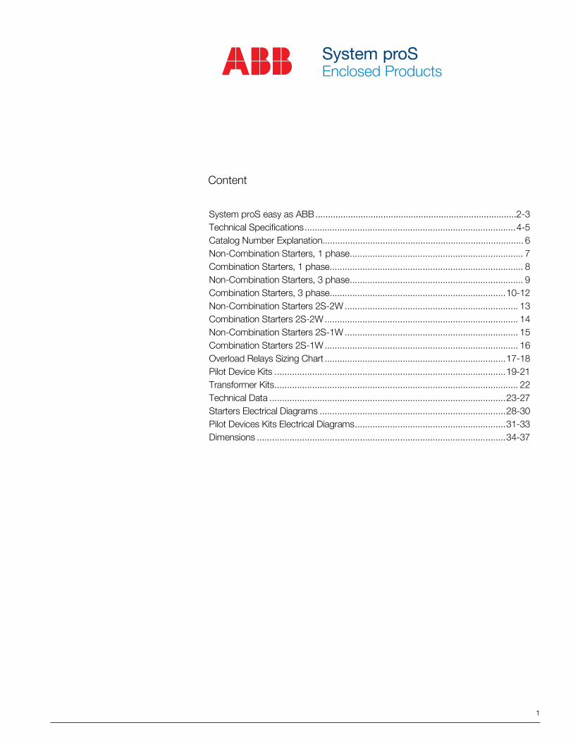
A. Install and secure your System proS on a wallB. Add overload relaysC. Install control transformer if required (pictures 1, 2
D. Install pilot device kit if required (pictures 3, 4)
E. Close the cover
System proSEasy as ABB
1 2
3 4
3
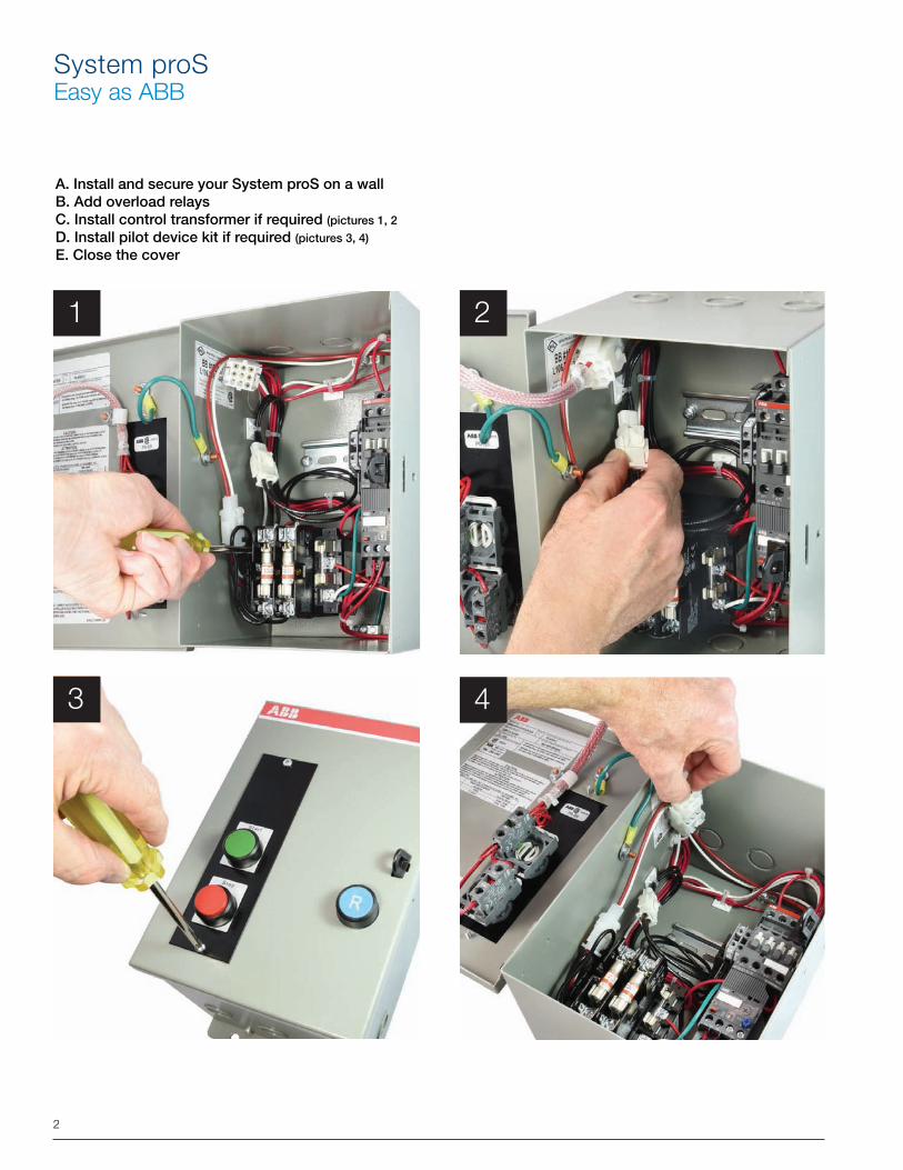
Transformer Kits O/L Relay
• Fused on primary and secondary• Primary voltage 120-208-240-347-416-480-600• Secondary voltage 24-120• Pre-wired and ready to install
System proS Pilot Device Kits• Pre-wired, ready-to-operate• One, two or three modules• Pushbuttons, pilot lights and selector switches
4
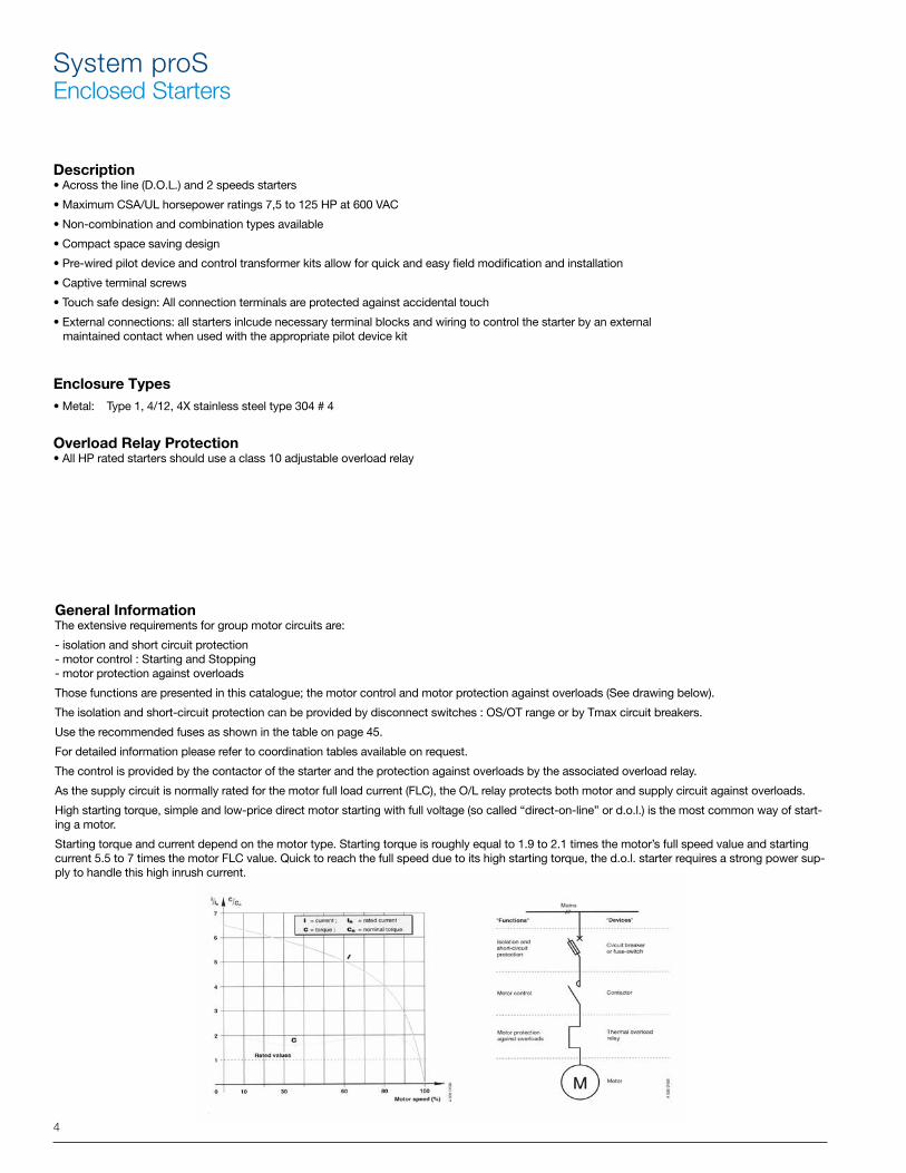
General InformationThe extensive requirements for group motor circuits are:
- isolation and short circuit protection - motor control : Starting and Stopping - motor protection against overloads
Those functions are presented in this catalogue; the motor control and motor protection against overloads (See drawing below).
The isolation and short-circuit protection can be provided by disconnect switches : OS/OT range or by Tmax circuit breakers.
Use the recommended fuses as shown in the table on page 45.
For detailed information please refer to coordination tables available on request.
The control is provided by the contactor of the starter and the protection against overloads by the associated overload relay.
As the supply circuit is normally rated for the motor full load current (FLC), the O/L relay protects both motor and supply circuit against overloads.
High starting torque, simple and low-price direct motor starting with full voltage (so called “direct-on-line” or d.o.l.) is the most common way of start-ing a motor.
Starting torque and current depend on the motor type. Starting torque is roughly equal to 1.9 to 2.1 times the motor’s full speed value and starting current 5.5 to 7 times the motor FLC value. Quick to reach the full speed due to its high starting torque, the d.o.l. starter requires a strong power sup-ply to handle this high inrush current.
System proSEnclosed Starters
Description• Across the line (D.O.L.) and 2 speeds starters
• Maximum CSA/UL horsepower ratings 7,5 to 125 HP at 600 VAC
• Non-combination and combination types available
• Compact space saving design
• Pre-wired pilot device and control transformer kits allow for quick and easy field modification and installation
• Captive terminal screws
• Touch safe design: All connection terminals are protected against accidental touch
• External connections: all starters inlcude necessary terminal blocks and wiring to control the starter by an external maintained contact when used with the appropriate pilot device kit
Enclosure Types• Metal: Type 1, 4/12, 4X stainless steel type 304 # 4
Overload Relay Protection• All HP rated starters should use a class 10 adjustable overload relay
5
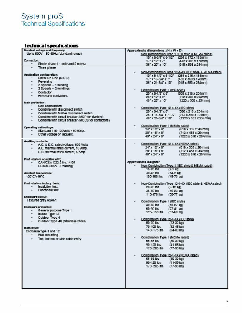
System proSTechnical Specifications
6
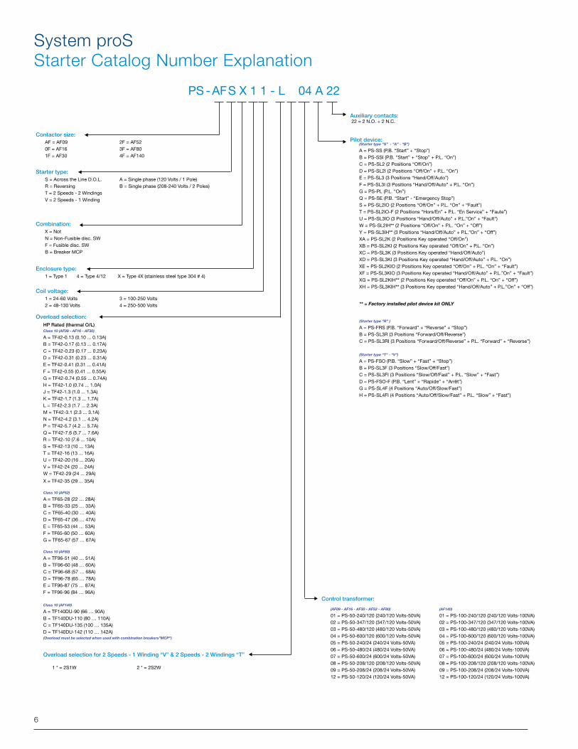
System proSStarter Catalog Number Explanation
Contactor size:AF = AF09 2F = AF520F = AF16 3F = AF801F = AF30 4F = AF140
Starter type: S = Across the Line D.O.L. A = Single phase (120 Volts / 1 Pole)R = Reversing B = Single phase (208-240 Volts / 2 Poles)T = 2 Speeds - 2 WindingsV = 2 Speeds - 1 Winding
Combination:X = NotN = Non-Fusible disc. SW F = Fusible disc. SW B = Breaker MCP
Enclosure type:1 = Type 1 4 = Type 4/12 X = Type 4X (stainless steel type 304 # 4)
Coil voltage:1 = 24-60 Volts 3 = 100-250 Volts 2 = 48-130 Volts 4 = 250-500 Volts
Overload selection: HP Rated (thermal O/L) Class 10 (AF09 - AF16 - AF30)
A = TF42-0.13 (0.10 ... 0.13A) B = TF42-0.17 (0.13 ... 0.17A)C = TF42-0.23 (0.17 ... 0.23A)D = TF42-0.31 (0.23 ... 0.31A)E = TF42-0.41 (0.31 ... 0.41A)F = TF42-0.55 (0.41 ... 0.55A)G = TF42-0.74 (0.55 ... 0.74A)H = TF42-1.0 (0.74 ... 1.0A)J = TF42-1.3 (1.0 ... 1.3A)K = TF42-1.7 (1.3 ... 1.7A)L = TF42-2.3 (1.7 ... 2.3A)M = TF42-3.1 (2.3 ... 3.1A)N = TF42-4.2 (3.1 ... 4.2A)P = TF42-5.7 (4.2 ... 5.7A)Q = TF42-7.6 (5.7 ... 7.6A)R = TF42-10 (7.6 ... 10A)S = TF42-13 (10 ... 13A)T = TF42-16 (13 ... 16A)U = TF42-20 (16 ... 20A)V = TF42-24 (20 ... 24A)W = TF42-29 (24 ... 29A)
X = TF42-35 (29 ... 35A)
Class 10 (AF52)
A = TF65-28 (22 … 28A)B = TF65-33 (25 … 33A)C = TF65-40 (30 … 40A)D = TF65-47 (36 … 47A)E = TF65-53 (44 … 53A)F = TF65-60 (50 … 60A)G = TF65-67 (57 … 67A)
Class 10 (AF80)
A = TF96-51 (40 … 51A)B = TF96-60 (48 … 60A)C = TF96-68 (57 … 68A)D = TF96-78 (65 … 78A)E = TF96-87 (75 … 87A)F = TF96-96 (84 … 96A)
Class 10 (AF140)
A = TF140DU-90 (66 … 90A)B = TF140DU-110 (80 … 110A)C = TF140DU-135 (100 … 135A)D = TF140DU-142 (110 … 142A)(Overload must be selected when used with combination breakers”MCP”)
Overload selection for 2 Speeds - 1 Winding “V” & 2 Speeds - 2 Windings “T”
1 * = 2S1W 2 * = 2S2W
Auxiliary contacts: 22 = 2 N.O. + 2 N.C.
Pilot device:(Starter type “S” - “A” - “B”)
A = PS-SS (P.B. “Start” + “Stop”)B = PS-SSI (P.B. “Start” + “Stop” + P.L. “On”)C = PS-SL2 (2 Positions “Off/On”)D = PS-SL2I (2 Positions “Off/On” + P.L. “On”)E = PS-SL3 (3 Positions “Hand/Off/Auto”)F = PS-SL3I (3 Positions “Hand/Off/Auto” + P.L. “On”)G = PS-PL (P.L. “On”)Q = PS-SE (P.B. “Start” - “Emergency Stop”)S = PS-SL2IO (2 Positions “Off/On” + P.L. “On” + “Fault”)T = PS-SL2IO-F (2 Positions “Hors/En” + P.L. “En Service” + “Faute”)U = PS-SL3IO (3 Positions “Hand/Off/Auto” + P.L.”On” + “Fault”)W = PS-SL2IH** (2 Positions “Off/On” + P.L. “On” + “Off”)Y = PS-SL3IH** (3 Positions “Hand/Off/Auto” + P.L.”On” + “Off”)XA = PS-SL2K (2 Positions Key operated “Off/On”)XB = PS-SL2KI (2 Positions Key operated “Off/On” + P.L. “On”)XC = PS-SL3K (3 Positions Key operated “Hand/Off/Auto”)XD = PS-SL3KI (3 Positions Key operated “Hand/Off/Auto” + P.L. “On”)XE = PS-SL2KIO (2 Positions Key operated “Off/On” + P.L. “On” + “Fault”)XF = PS-SL3KIO (3 Positions Key operated “Hand/Off/Auto” + P.L.”On” + “Fault”)XG = PS-SL2KIH** (2 Positions Key operated “Off/On” + P.L. “On” + “Off”)XH = PS-SL3KIH** (3 Positions Key operated “Hand/Off/Auto” + P.L.”On” + “Off”)
** = Factory installed pilot device kit ONLY
(Starter type “R” )
A = PS-FRS (P.B. “Forward” + “Reverse” + “Stop”)B = PS-SL3R (3 Positions “Forward/Off/Reverse”)C = PS-SL3RI (3 Positions “Forward/Off/Reverse” + P.L. “Forward” + “Reverse”)
(Starter type “T” - “V”)
A = PS-FSO (P.B. “Slow” + “Fast” + “Stop”)B = PS-SL3F (3 Positions “Slow/Off/Fast”)C = PS-SL3FI (3 Positions “Slow/Off/Fast” + P.L. “Slow” + “Fast”)D = PS-FSO-F (P.B. “Lent” + “Rapide” + “Arrêt”)G = PS-SL4F (4 Positions “Auto/Off/Slow/Fast”)H = PS-SL4FI (4 Positions “Auto/Off/Slow/Fast” + P.L. “Slow” + “Fast”)
PS - AF S X 1 1 - L 04 A 22
Control transformer:
(AF09 - AF16 - AF30 - AF52 - AF80)
01 = PS-50-240/120 (240/120 Volts-50VA)02 = PS-50-347/120 (347/120 Volts-50VA)03 = PS-50-480/120 (480/120 Volts-50VA)04 = PS-50-600/120 (600/120 Volts-50VA)05 = PS-50-240/24 (240/24 Volts-50VA)06 = PS-50-480/24 (480/24 Volts-50VA)07 = PS-50-600/24 (600/24 Volts-50VA)08 = PS-50-208/120 (208/120 Volts-50VA)09 = PS-50-208/24 (208/24 Volts-50VA)12 = PS-50-120/24 (120/24 Volts-50VA)
(AF140)
01 = PS-100-240/120 (240/120 Volts-100VA)02 = PS-100-347/120 (347/120 Volts-100VA)03 = PS-100-480/120 (480/120 Volts-100VA)04 = PS-100-600/120 (600/120 Volts-100VA)05 = PS-100-240/24 (240/24 Volts-100VA)06 = PS-100-480/24 (480/24 Volts-100VA)07 = PS-100-600/24 (600/24 Volts-100VA)08 = PS-100-208/120 (208/120 Volts-100VA)09 = PS-100-208/24 (208/24 Volts-100VA)12 = PS-100-120/24 (120/24 Volts-100VA)
7
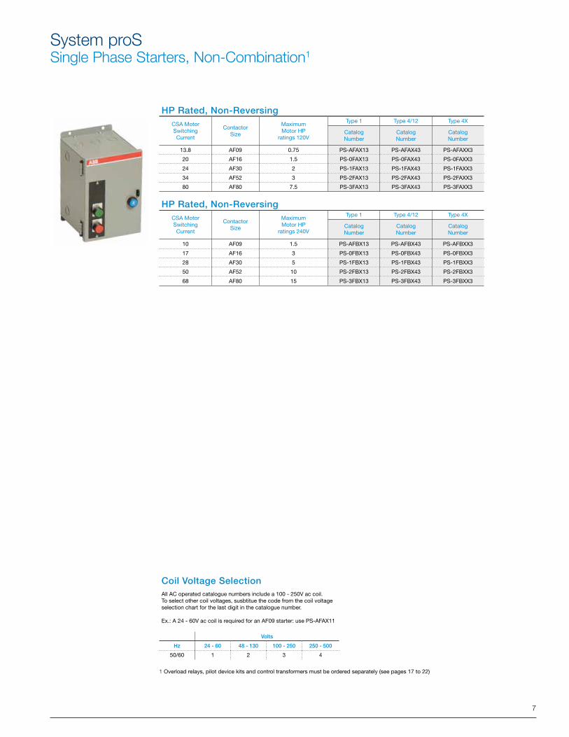
System proSSingle Phase Starters, Non-Combination1
HP Rated, Non-Reversing
HP Rated, Non-Reversing
Coil Voltage SelectionAll AC operated catalogue numbers include a 100 - 250V ac coil.To select other coil voltages, susbtitue the code from the coil voltage selection chart for the last digit in the catalogue number.
Ex.: A 24 - 60V ac coil is required for an AF09 starter: use PS-AFAX11
Volts
Hz 24 - 60 48 - 130 100 - 250 250 - 500
50/60 1 2 3 4
1 Overload relays, pilot device kits and control transformers must be ordered separately (see pages 17 to 22)
CSA MotorSwitchingCurrent
ContactorSize
Maximum Motor HP
ratings 120V
Type 1 Type 4/12 Type 4X
CatalogNumber
CatalogNumber
CatalogNumber
13.8 AF09 0.75 PS-AFAX13 PS-AFAX43 PS-AFAXX3
20 AF16 1.5 PS-0FAX13 PS-0FAX43 PS-0FAXX3
24 AF30 2 PS-1FAX13 PS-1FAX43 PS-1FAXX3
34 AF52 3 PS-2FAX13 PS-2FAX43 PS-2FAXX3
80 AF80 7.5 PS-3FAX13 PS-3FAX43 PS-3FAXX3
CSA MotorSwitchingCurrent
ContactorSize
Maximum Motor HP
ratings 240V
Type 1 Type 4/12 Type 4X
CatalogNumber
CatalogNumber
CatalogNumber
10 AF09 1.5 PS-AFBX13 PS-AFBX43 PS-AFBXX3
17 AF16 3 PS-0FBX13 PS-0FBX43 PS-0FBXX3
28 AF30 5 PS-1FBX13 PS-1FBX43 PS-1FBXX3
50 AF52 10 PS-2FBX13 PS-2FBX43 PS-2FBXX3
68 AF80 15 PS-3FBX13 PS-3FBX43 PS-3FBXX3
8
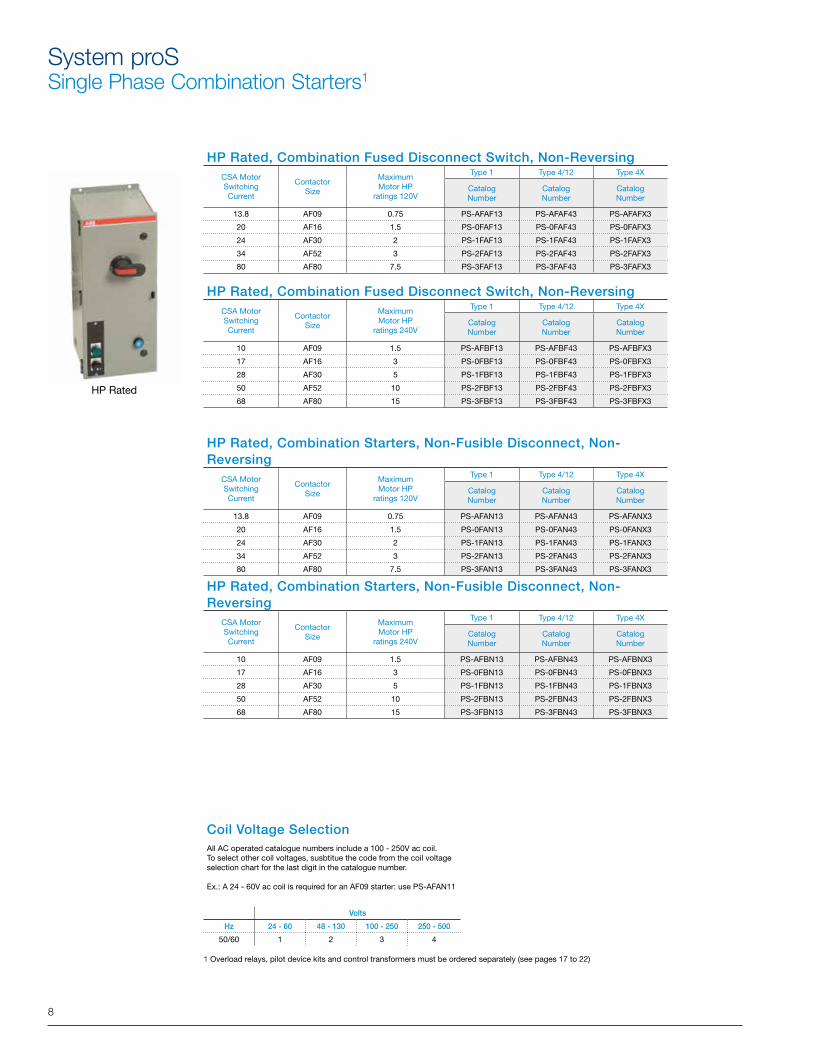
System proSSingle Phase Combination Starters1
HP Rated, Combination Fused Disconnect Switch, Non-Reversing
HP Rated, Combination Fused Disconnect Switch, Non-Reversing
Coil Voltage SelectionAll AC operated catalogue numbers include a 100 - 250V ac coil. To select other coil voltages, susbtitue the code from the coil voltage selection chart for the last digit in the catalogue number.
Ex.: A 24 - 60V ac coil is required for an AF09 starter: use PS-AFAN11
Volts
Hz 24 - 60 48 - 130 100 - 250 250 - 500
50/60 1 2 3 4
1 Overload relays, pilot device kits and control transformers must be ordered separately (see pages 17 to 22)
HP Rated
HP Rated, Combination Starters, Non-Fusible Disconnect, Non-Reversing
HP Rated, Combination Starters, Non-Fusible Disconnect, Non-Reversing
CSA MotorSwitchingCurrent
ContactorSize
Maximum Motor HP
ratings 120V
Type 1 Type 4/12 Type 4X
CatalogNumber
CatalogNumber
CatalogNumber
13.8 AF09 0.75 PS-AFAF13 PS-AFAF43 PS-AFAFX3
20 AF16 1.5 PS-0FAF13 PS-0FAF43 PS-0FAFX3
24 AF30 2 PS-1FAF13 PS-1FAF43 PS-1FAFX3
34 AF52 3 PS-2FAF13 PS-2FAF43 PS-2FAFX3
80 AF80 7.5 PS-3FAF13 PS-3FAF43 PS-3FAFX3
CSA MotorSwitchingCurrent
ContactorSize
Maximum Motor HP
ratings 240V
Type 1 Type 4/12 Type 4X
CatalogNumber
CatalogNumber
CatalogNumber
10 AF09 1.5 PS-AFBF13 PS-AFBF43 PS-AFBFX3
17 AF16 3 PS-0FBF13 PS-0FBF43 PS-0FBFX3
28 AF30 5 PS-1FBF13 PS-1FBF43 PS-1FBFX3
50 AF52 10 PS-2FBF13 PS-2FBF43 PS-2FBFX3
68 AF80 15 PS-3FBF13 PS-3FBF43 PS-3FBFX3
CSA MotorSwitchingCurrent
ContactorSize
Maximum Motor HP
ratings 120V
Type 1 Type 4/12 Type 4X
CatalogNumber
CatalogNumber
CatalogNumber
13.8 AF09 0.75 PS-AFAN13 PS-AFAN43 PS-AFANX3
20 AF16 1.5 PS-0FAN13 PS-0FAN43 PS-0FANX3
24 AF30 2 PS-1FAN13 PS-1FAN43 PS-1FANX3
34 AF52 3 PS-2FAN13 PS-2FAN43 PS-2FANX3
80 AF80 7.5 PS-3FAN13 PS-3FAN43 PS-3FANX3
CSA MotorSwitchingCurrent
ContactorSize
Maximum Motor HP
ratings 240V
Type 1 Type 4/12 Type 4X
CatalogNumber
CatalogNumber
CatalogNumber
10 AF09 1.5 PS-AFBN13 PS-AFBN43 PS-AFBNX3
17 AF16 3 PS-0FBN13 PS-0FBN43 PS-0FBNX3
28 AF30 5 PS-1FBN13 PS-1FBN43 PS-1FBNX3
50 AF52 10 PS-2FBN13 PS-2FBN43 PS-2FBNX3
68 AF80 15 PS-3FBN13 PS-3FBN43 PS-3FBNX3
9
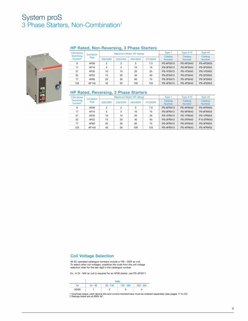
System proS3 Phase Starters, Non-Combination1
1 Overload relays, pilot device kits and control transformers must be ordered separately (see pages 17 to 22)2 Ratings listed are at 600V AC
HP Rated, Non-Reversing, 3 Phase Starters
HP Rated, Reversing, 3 Phase Starters
Coil Voltage SelectionAll AC operated catalogue numbers include a 100 - 250V ac coil.To select other coil voltages, susbtitue the code from the coil voltage selection chart for the last digit in the catalogue number.
Ex.: A 24 - 60V ac coil is required for an AF09 starter: use PS-AFSX11
Volts
Hz 24 - 60 48 - 130 100 - 250 250 - 500
50/60 1 2 3 4
CSA MotorSwitchingCurrent2
ContactorSize
Maximum Motor HP ratings Type 1 Type 4/12 Type 4X
CatalogNumber
CatalogNumber
CatalogNumber200/208V 220/240V 460/480V 575/600V
9 AF09 2 2 5 7.5 PS-AFSX13 PS-AFSX43 PS-AFSXX3
17 AF16 5 5 10 15 PS-0FSX13 PS-0FSX43 PS-0FSXX3
27 AF30 10 10 20 25 PS-1FSX13 PS-1FSX43 PS-1FSXX3
52 AF52 15 20 40 50 PS-2FSX13 PS-2FSX43 PS-2FSXX3
77 AF80 25 30 60 75 PS-3FSX13 PS-3FSX43 PS-3FSXX3
125 AF140 40 50 100 125 PS-4FSX13 PS-4FSX43 PS-4FSXX3
CSA MotorSwitchingCurrent2
ContactorSize
Maximum Motor HP ratings Type 1 Type 4/12 Type 4X
200/208V 220/240V 460/480V 575/600VCatalogNumber
CatalogNumber
CatalogNumber
9 AF09 2 2 5 7.5 PS-AFRX13 PS-AFRX43 PS-AFRXX3
17 AF16 5 5 10 15 PS-0FRX13 PS-0FRX43 PS-0FRXX3
27 AF30 10 10 20 25 PS-1FRX13 PS-1FRX43 PS-1FRXX3
52 AF52 15 20 40 50 PS-2FRX13 PS-2FRX43 P S-2FRXX3
77 AF80 25 30 60 75 PS-3FRX13 PS-3FRX43 PS-3FRXX3
125 AF140 40 50 100 125 PS-4FRX13 PS-4FRX43 PS-4FRXX3
10
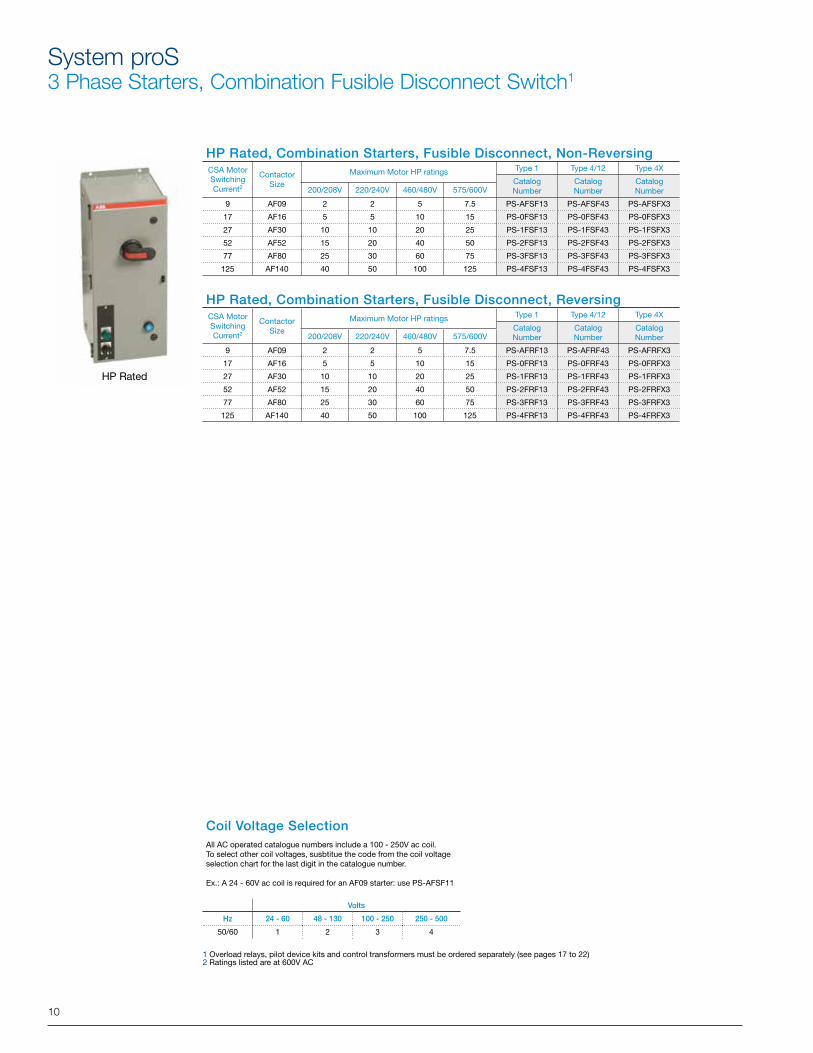
System proS3 Phase Starters, Combination Fusible Disconnect Switch1
HP Rated
Coil Voltage SelectionAll AC operated catalogue numbers include a 100 - 250V ac coil.To select other coil voltages, susbtitue the code from the coil voltage selection chart for the last digit in the catalogue number.
Ex.: A 24 - 60V ac coil is required for an AF09 starter: use PS-AFSF11
Volts
Hz 24 - 60 48 - 130 100 - 250 250 - 500
50/60 1 2 3 4
HP Rated, Combination Starters, Fusible Disconnect, Non-Reversing
HP Rated, Combination Starters, Fusible Disconnect, Reversing
1 Overload relays, pilot device kits and control transformers must be ordered separately (see pages 17 to 22)2 Ratings listed are at 600V AC
CSA MotorSwitchingCurrent2
ContactorSize
Maximum Motor HP ratings Type 1 Type 4/12 Type 4X
CatalogNumber
CatalogNumber
CatalogNumber200/208V 220/240V 460/480V 575/600V
9 AF09 2 2 5 7.5 PS-AFSF13 PS-AFSF43 PS-AFSFX3
17 AF16 5 5 10 15 PS-0FSF13 PS-0FSF43 PS-0FSFX3
27 AF30 10 10 20 25 PS-1FSF13 PS-1FSF43 PS-1FSFX3
52 AF52 15 20 40 50 PS-2FSF13 PS-2FSF43 PS-2FSFX3
77 AF80 25 30 60 75 PS-3FSF13 PS-3FSF43 PS-3FSFX3
125 AF140 40 50 100 125 PS-4FSF13 PS-4FSF43 PS-4FSFX3
CSA MotorSwitchingCurrent2
ContactorSize
Maximum Motor HP ratings Type 1 Type 4/12 Type 4X
CatalogNumber
CatalogNumber
CatalogNumber200/208V 220/240V 460/480V 575/600V
9 AF09 2 2 5 7.5 PS-AFRF13 PS-AFRF43 PS-AFRFX3
17 AF16 5 5 10 15 PS-0FRF13 PS-0FRF43 PS-0FRFX3
27 AF30 10 10 20 25 PS-1FRF13 PS-1FRF43 PS-1FRFX3
52 AF52 15 20 40 50 PS-2FRF13 PS-2FRF43 PS-2FRFX3
77 AF80 25 30 60 75 PS-3FRF13 PS-3FRF43 PS-3FRFX3
125 AF140 40 50 100 125 PS-4FRF13 PS-4FRF43 PS-4FRFX3
11
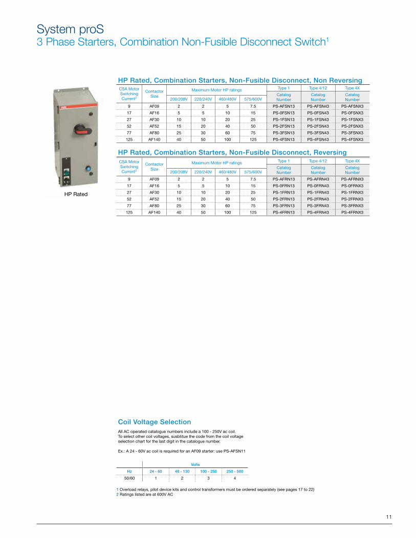
System proS3 Phase Starters, Combination Non-Fusible Disconnect Switch1
HP Rated
Coil Voltage SelectionAll AC operated catalogue numbers include a 100 - 250V ac coil.To select other coil voltages, susbtitue the code from the coil voltage selection chart for the last digit in the catalogue number.
Ex.: A 24 - 60V ac coil is required for an AF09 starter: use PS-AFSN11
Volts
Hz 24 - 60 48 - 130 100 - 250 250 - 500
50/60 1 2 3 4
1 Overload relays, pilot device kits and control transformers must be ordered separately (see pages 17 to 22) 2 Ratings listed are at 600V AC
HP Rated, Combination Starters, Non-Fusible Disconnect, Non Reversing
HP Rated, Combination Starters, Non-Fusible Disconnect, Reversing
CSA MotorSwitchingCurrent2
ContactorSize
Maximum Motor HP ratings Type 1 Type 4/12 Type 4X
CatalogNumber
CatalogNumber
CatalogNumber200/208V 220/240V 460/480V 575/600V
9 AF09 2 2 5 7.5 PS-AFSN13 PS-AFSN43 PS-AFSNX3
17 AF16 5 5 10 15 PS-0FSN13 PS-0FSN43 PS-0FSNX3
27 AF30 10 10 20 25 PS-1FSN13 PS-1FSN43 PS-1FSNX3
52 AF52 15 20 40 50 PS-2FSN13 PS-2FSN43 PS-2FSNX3
77 AF80 25 30 60 75 PS-3FSN13 PS-3FSN43 PS-3FSNX3
125 AF140 40 50 100 125 PS-4FSN13 PS-4FSN43 PS-4FSNX3
CSA MotorSwitchingCurrent2
ContactorSize
Maximum Motor HP ratings Type 1 Type 4/12 Type 4X
CatalogNumber
CatalogNumber
CatalogNumber200/208V 220/240V 460/480V 575/600V
9 AF09 2 2 5 7.5 PS-AFRN13 PS-AFRN43 PS-AFRNX3
17 AF16 5 5 10 15 PS-0FRN13 PS-0FRN43 PS-0FRNX3
27 AF30 10 10 20 25 PS-1FRN13 PS-1FRN43 PS-1FRNX3
52 AF52 15 20 40 50 PS-2FRN13 PS-2FRN43 PS-2FRNX3
77 AF80 25 30 60 75 PS-3FRN13 PS-3FRN43 PS-3FRNX3
125 AF140 40 50 100 125 PS-4FRN13 PS-4FRN43 PS-4FRNX3
12
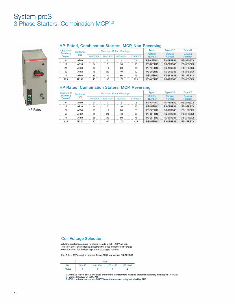
System proS3 Phase Starters, Combination MCP1,3
HP Rated
Coil Voltage SelectionAll AC operated catalogue numbers include a 100 - 250V ac coil.To select other coil voltages, susbtitue the code from the coil voltage selection chart for the last digit in the catalogue number.
Ex.: A 24 - 60V ac coil is required for an AF09 starter: use PS-AFSB11
Volts
Hz 24 - 60 48 - 130 100 - 250 250 - 500
50/60 1 2 3 4
1 Overload relays, pilot device kits and control transformers must be ordered separately (see pages 17 to 22)2 Ratings listed are at 600V AC 3 MCP combination starters MUST have the overload relay installed by ABB.
HP-Rated, Combination Starters, MCP, Non-Reversing
HP Rated, Combination Staters, MCP, Reversing
CSA MotorSwitchingCurrent2
ContactorSize
Maximum Motor HP ratings Type 1 Type 4/12 Type 4X
CatalogNumber
CatalogNumber
CatalogNumber200/208V 220/240V 460/480V 575/600V
9 AF09 2 2 5 7.5 PS-AFSB13 PS-AFSB43 PS-AFSBX3
17 AF16 5 5 10 15 PS-0FSB13 PS-0FSB43 PS-0FSBX3
27 AF30 10 10 20 25 PS-1FSB13 PS-1FSB43 PS-1FSBX3
52 AF52 15 20 40 50 PS-2FSB13 PS-2FSB43 PS-2FSBX3
77 AF80 25 30 60 75 PS-3FSB13 PS-3FSB43 PS-3FSBX3
125 AF140 40 50 100 125 PS-4FSB13 PS-4FSB43 PS-4FSBX3
CSA MotorSwitchingCurrent2
ContactorSize
Maximum Motor HP ratings Type 1 Type 4/12 Type 4X
CatalogNumber
CatalogNumber
CatalogNumber200/208V 220/240V 460/480V 575/600V
9 AF09 2 2 5 7.5 PS-AFRB13 PS-AFRB43 PS-AFRBX3
17 AF16 5 5 10 15 PS-0FRB13 PS-0FRB43 PS-0FRBX3
27 AF30 10 10 20 25 PS-1FRB13 PS-1FRB43 PS-1FRBX3
52 AF52 15 20 40 50 PS-2FRB13 PS-2FRB43 PS-2FRBX3
77 AF80 25 30 60 75 PS-3FRB13 PS-3FRB43 PS-3FRBX3
125 AF140 40 50 100 125 PS-4FRB13 PS-4FRB43 PS-4FRBX3
13
1 Overload relays, pilot device kits and control transformers must be ordered separately (see pages 17 to 22)2 Ratings listed are at 600V AC 3 MCP combination starters MUST have the overload relay installed by ABB.
CSA MotorSwitchingCurrent2
ContactorSize
Maximum Motor HP ratings Type 1 Type 4/12 Type 4X
CatalogNumber
CatalogNumber
CatalogNumber200/208V 220/240V 460/480V 575/600V
9 AF09 2 2 5 7.5 PS-AFSB13 PS-AFSB43 PS-AFSBX3
17 AF16 5 5 10 15 PS-0FSB13 PS-0FSB43 PS-0FSBX3
27 AF30 10 10 20 25 PS-1FSB13 PS-1FSB43 PS-1FSBX3
52 AF52 15 20 40 50 PS-2FSB13 PS-2FSB43 PS-2FSBX3
77 AF80 25 30 60 75 PS-3FSB13 PS-3FSB43 PS-3FSBX3
125 AF140 40 50 100 125 PS-4FSB13 PS-4FSB43 PS-4FSBX3
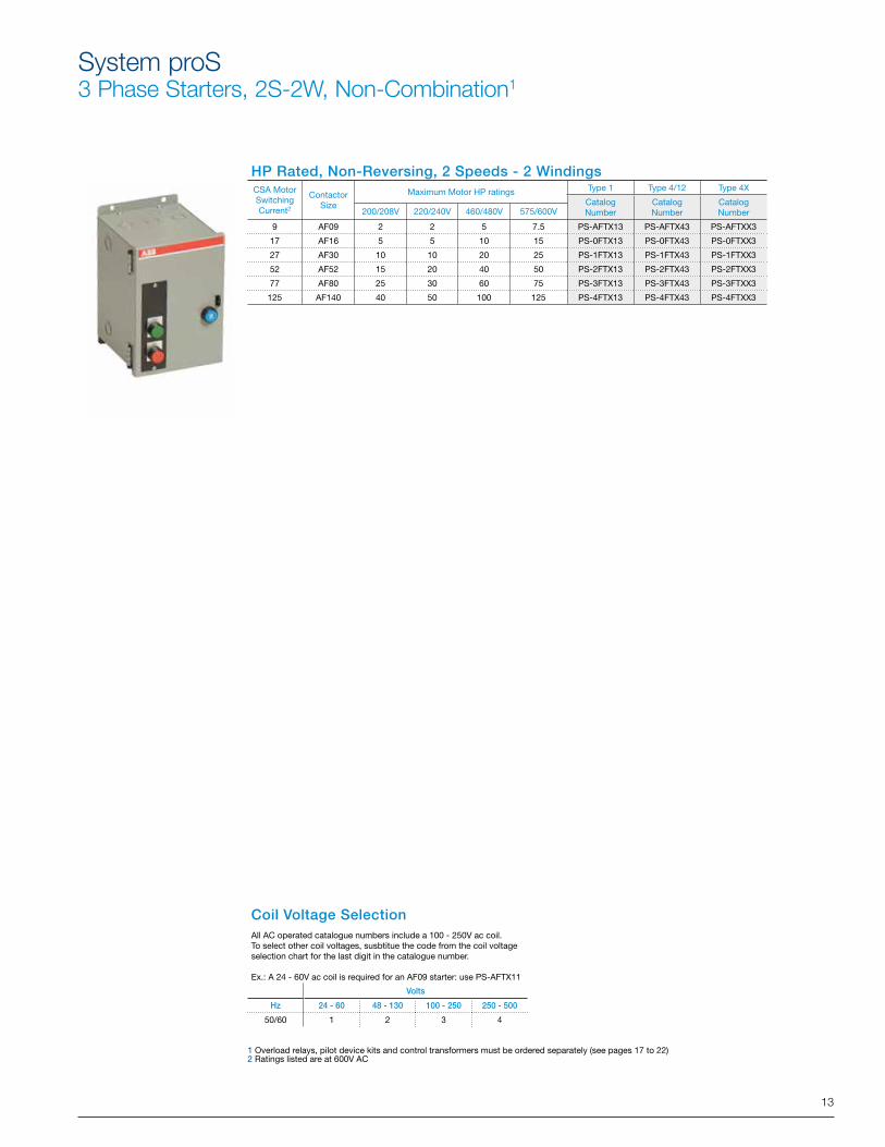
System proS3 Phase Starters, 2S-2W, Non-Combination1
HP Rated, Non-Reversing, 2 Speeds - 2 Windings
Coil Voltage Selection All AC operated catalogue numbers include a 100 - 250V ac coil.To select other coil voltages, susbtitue the code from the coil voltage selection chart for the last digit in the catalogue number.
Ex.: A 24 - 60V ac coil is required for an AF09 starter: use PS-AFTX11
Volts
Hz 24 - 60 48 - 130 100 - 250 250 - 500
50/60 1 2 3 4
1 Overload relays, pilot device kits and control transformers must be ordered separately (see pages 17 to 22) 2 Ratings listed are at 600V AC
CSA MotorSwitchingCurrent2
ContactorSize
Maximum Motor HP ratings Type 1 Type 4/12 Type 4X
CatalogNumber
CatalogNumber
CatalogNumber200/208V 220/240V 460/480V 575/600V
9 AF09 2 2 5 7.5 PS-AFTX13 PS-AFTX43 PS-AFTXX3
17 AF16 5 5 10 15 PS-0FTX13 PS-0FTX43 PS-0FTXX3
27 AF30 10 10 20 25 PS-1FTX13 PS-1FTX43 PS-1FTXX3
52 AF52 15 20 40 50 PS-2FTX13 PS-2FTX43 PS-2FTXX3
77 AF80 25 30 60 75 PS-3FTX13 PS-3FTX43 PS-3FTXX3
125 AF140 40 50 100 125 PS-4FTX13 PS-4FTX43 PS-4FTXX3
14
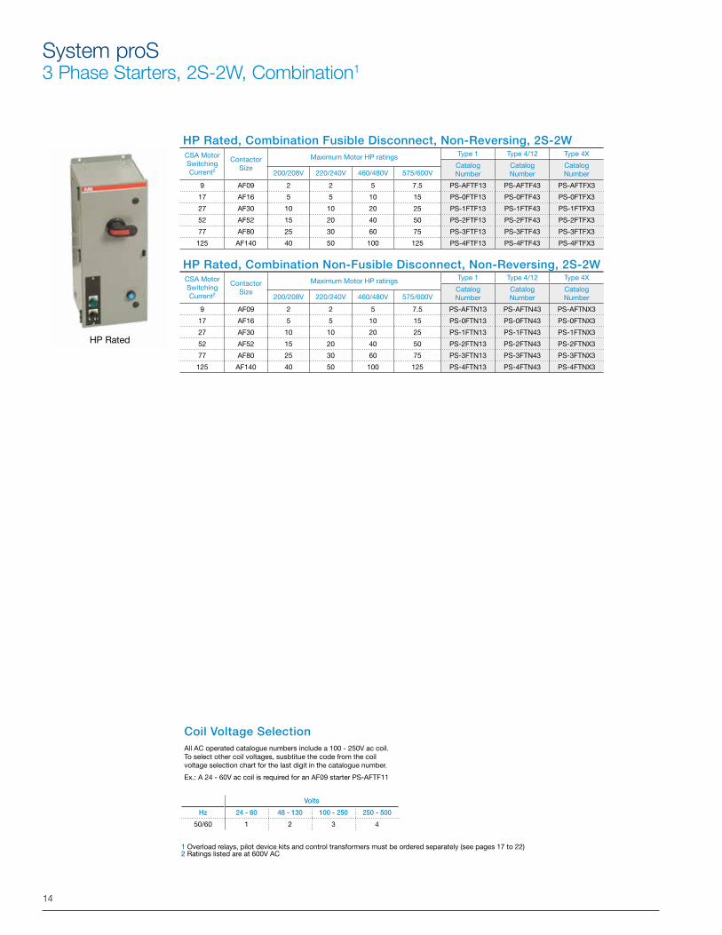
System proS3 Phase Starters, 2S-2W, Combination1
HP Rated
Coil Voltage Selection All AC operated catalogue numbers include a 100 - 250V ac coil. To select other coil voltages, susbtitue the code from the coil voltage selection chart for the last digit in the catalogue number.
Ex.: A 24 - 60V ac coil is required for an AF09 starter PS-AFTF11
Volts
Hz 24 - 60 48 - 130 100 - 250 250 - 500
50/60 1 2 3 4
1 Overload relays, pilot device kits and control transformers must be ordered separately (see pages 17 to 22)2 Ratings listed are at 600V AC
HP Rated, Combination Fusible Disconnect, Non-Reversing, 2S-2W
HP Rated, Combination Non-Fusible Disconnect, Non-Reversing, 2S-2W
CSA MotorSwitchingCurrent2
ContactorSize
Maximum Motor HP ratings Type 1 Type 4/12 Type 4X
CatalogNumber
CatalogNumber
CatalogNumber200/208V 220/240V 460/480V 575/600V
9 AF09 2 2 5 7.5 PS-AFTF13 PS-AFTF43 PS-AFTFX3
17 AF16 5 5 10 15 PS-0FTF13 PS-0FTF43 PS-0FTFX3
27 AF30 10 10 20 25 PS-1FTF13 PS-1FTF43 PS-1FTFX3
52 AF52 15 20 40 50 PS-2FTF13 PS-2FTF43 PS-2FTFX3
77 AF80 25 30 60 75 PS-3FTF13 PS-3FTF43 PS-3FTFX3
125 AF140 40 50 100 125 PS-4FTF13 PS-4FTF43 PS-4FTFX3
CSA MotorSwitchingCurrent2
ContactorSize
Maximum Motor HP ratings Type 1 Type 4/12 Type 4X
CatalogNumber
CatalogNumber
CatalogNumber200/208V 220/240V 460/480V 575/600V
9 AF09 2 2 5 7.5 PS-AFTN13 PS-AFTN43 PS-AFTNX3
17 AF16 5 5 10 15 PS-0FTN13 PS-0FTN43 PS-0FTNX3
27 AF30 10 10 20 25 PS-1FTN13 PS-1FTN43 PS-1FTNX3
52 AF52 15 20 40 50 PS-2FTN13 PS-2FTN43 PS-2FTNX3
77 AF80 25 30 60 75 PS-3FTN13 PS-3FTN43 PS-3FTNX3
125 AF140 40 50 100 125 PS-4FTN13 PS-4FTN43 PS-4FTNX3
15
System proS3 Phase 2S-1W Starters, Non-Combination1
HP Rated, Non-Reversing, 2 Speeds - 1 Windings
Coil Voltage SelectionAll AC operated catalogue numbers include a 100 - 250V ac coil.To select other coil voltages, susbtitue the code from the coil voltage selection chart for the last digit in the catalogue number.
Ex.: A 24 - 60V ac coil is required for an AF09 starter: use PS-AFVX11
Volts
Hz 24 - 60 48 - 130 100 - 250 250 - 500
50/60 1 2 3 4
1 Overload relays, pilot device kits and control transformers must be ordered separately (see pages 17 to 22)2 Ratings listed are at 600V AC
CSA MotorSwitchingCurrent2
ContactorSize
Maximum Motor HP ratings Type 1 Type 4/12 Type 4X
CatalogNumber
CatalogNumber
CatalogNumber200/208V 220/240V 460/480V 575/600V
9 AF09 2 2 5 7.5 PS-AFVX13 PS-AFVX43 PS-AFVXX3
17 AF16 5 5 10 15 PS-0FVX13 PS-0FVX43 PS-0FVXX3
27 AF30 10 10 20 25 PS-1FVX13 PS-1FVX43 PS-1FVXX3
52 AF52 15 20 40 50 PS-2FVX13 PS-2FVX43 PS-2FVXX3
77 AF80 25 30 60 75 PS-3FVX13 PS-3FVX43 PS-3FVXX3
125 AF140 40 50 100 125 PS-4FVX13 PS-4FVX43 PS-4FVXX3
16
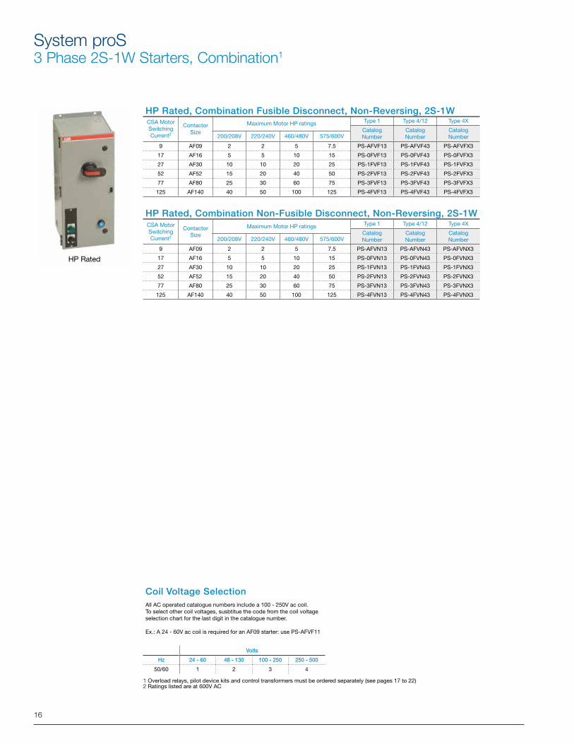
System proS3 Phase 2S-1W Starters, Combination1
HP Rated
Coil Voltage SelectionAll AC operated catalogue numbers include a 100 - 250V ac coil.To select other coil voltages, susbtitue the code from the coil voltage selection chart for the last digit in the catalogue number.
Ex.: A 24 - 60V ac coil is required for an AF09 starter: use PS-AFVF11
Volts
Hz 24 - 60 48 - 130 100 - 250 250 - 500
50/60 1 2 3 4
1 Overload relays, pilot device kits and control transformers must be ordered separately (see pages 17 to 22)2 Ratings listed are at 600V AC
HP Rated, Combination Fusible Disconnect, Non-Reversing, 2S-1W
HP Rated, Combination Non-Fusible Disconnect, Non-Reversing, 2S-1W
CSA MotorSwitchingCurrent2
ContactorSize
Maximum Motor HP ratings Type 1 Type 4/12 Type 4X
CatalogNumber
CatalogNumber
CatalogNumber200/208V 220/240V 460/480V 575/600V
9 AF09 2 2 5 7.5 PS-AFVF13 PS-AFVF43 PS-AFVFX3
17 AF16 5 5 10 15 PS-0FVF13 PS-0FVF43 PS-0FVFX3
27 AF30 10 10 20 25 PS-1FVF13 PS-1FVF43 PS-1FVFX3
52 AF52 15 20 40 50 PS-2FVF13 PS-2FVF43 PS-2FVFX3
77 AF80 25 30 60 75 PS-3FVF13 PS-3FVF43 PS-3FVFX3
125 AF140 40 50 100 125 PS-4FVF13 PS-4FVF43 PS-4FVFX3
CSA MotorSwitchingCurrent2
ContactorSize
Maximum Motor HP ratings Type 1 Type 4/12 Type 4X
CatalogNumber
CatalogNumber
CatalogNumber200/208V 220/240V 460/480V 575/600V
9 AF09 2 2 5 7.5 PS-AFVN13 PS-AFVN43 PS-AFVNX3
17 AF16 5 5 10 15 PS-0FVN13 PS-0FVN43 PS-0FVNX3
27 AF30 10 10 20 25 PS-1FVN13 PS-1FVN43 PS-1FVNX3
52 AF52 15 20 40 50 PS-2FVN13 PS-2FVN43 PS-2FVNX3
77 AF80 25 30 60 75 PS-3FVN13 PS-3FVN43 PS-3FVNX3
125 AF140 40 50 100 125 PS-4FVN13 PS-4FVN43 PS-4FVNX3
17
CSA MotorSwitchingCurrent2
ContactorSize
Maximum Motor HP ratings Type 1 Type 4/12 Type 4X
CatalogNumber
CatalogNumber
CatalogNumber200/208V 220/240V 460/480V 575/600V
9 AF09 2 2 5 7.5 PS-AFVF13 PS-AFVF43 PS-AFVFX3
17 AF16 5 5 10 15 PS-0FVF13 PS-0FVF43 PS-0FVFX3
27 AF30 10 10 20 25 PS-1FVF13 PS-1FVF43 PS-1FVFX3
52 AF52 15 20 40 50 PS-2FVF13 PS-2FVF43 PS-2FVFX3
77 AF80 25 30 60 75 PS-3FVF13 PS-3FVF43 PS-3FVFX3
125 AF140 40 50 100 125 PS-4FVF13 PS-4FVF43 PS-4FVFX3
CSA MotorSwitchingCurrent2
ContactorSize
Maximum Motor HP ratings Type 1 Type 4/12 Type 4X
CatalogNumber
CatalogNumber
CatalogNumber200/208V 220/240V 460/480V 575/600V
9 AF09 2 2 5 7.5 PS-AFVN13 PS-AFVN43 PS-AFVNX3
17 AF16 5 5 10 15 PS-0FVN13 PS-0FVN43 PS-0FVNX3
27 AF30 10 10 20 25 PS-1FVN13 PS-1FVN43 PS-1FVNX3
52 AF52 15 20 40 50 PS-2FVN13 PS-2FVN43 PS-2FVNX3
77 AF80 25 30 60 75 PS-3FVN13 PS-3FVN43 PS-3FVNX3
125 AF140 40 50 100 125 PS-4FVN13 PS-4FVN43 PS-4FVNX3
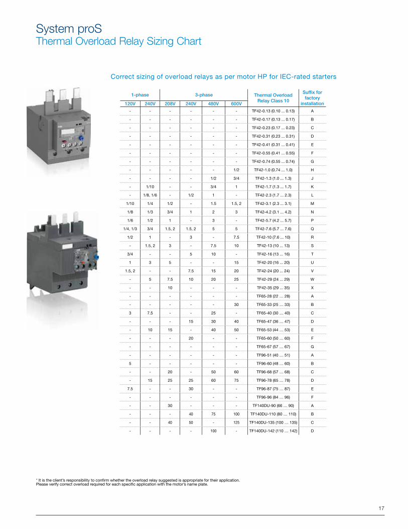
System proSThermal Overload Relay Sizing Chart
1-phase 3-phase Thermal Overload Relay Class 10
Suffix for factory
installation120V 240V 208V 240V 480V 600V
- - - - - - TF42-0.13 (0.10 ... 0.13) A
- - - - - - TF42-0.17 (0.13 ... 0.17) B
- - - - - - TF42-0.23 (0.17 ... 0.23) C
- - - - - - TF42-0.31 (0.23 ... 0.31) D
- - - - - - TF42-0.41 (0.31 ... 0.41) E
- - - - - - TF42-0.55 (0.41 ... 0.55) F
- - - - - - TF42-0.74 (0.55 ... 0.74) G
- - - - - 1/2 TF42-1.0 (0.74 ... 1.0) H
- - - - 1/2 3/4 TF42-1.3 (1.0 ... 1.3) J
- 1/10 - - 3/4 1 TF42-1.7 (1.3 ... 1.7) K
- 1/8, 1/6 - 1/2 1 - TF42-2.3 (1.7 ... 2.3) L
1/10 1/4 1/2 - 1.5 1.5, 2 TF42-3.1 (2.3 ... 3.1) M
1/8 1/3 3/4 1 2 3 TF42-4.2 (3.1 ... 4.2) N
1/6 1/2 1 - 3 - TF42-5.7 (4.2 ... 5.7) P
1/4, 1/3 3/4 1.5, 2 1.5, 2 5 5 TF42-7.6 (5.7 ... 7.6) Q
1/2 1 - 3 - 7.5 TF42-10 (7.6 ... 10) R
- 1.5, 2 3 - 7.5 10 TF42-13 (10 ... 13) S
3/4 - - 5 10 - TF42-16 (13 ... 16) T
1 3 5 - - 15 TF42-20 (16 ... 20) U
1.5, 2 - - 7.5 15 20 TF42-24 (20 ... 24) V
- 5 7.5 10 20 25 TF42-29 (24 ... 29) W
- - 10 - - - TF42-35 (29 ... 35) X
- - - - - - TF65-28 (22 … 28) A
- - - - - 30 TF65-33 (25 … 33) B
3 7.5 - - 25 - TF65-40 (30 … 40) C
- - - 15 30 40 TF65-47 (36 … 47) D
- 10 15 - 40 50 TF65-53 (44 … 53) E
- - - 20 - - TF65-60 (50 … 60) F
- - - - - - TF65-67 (57 … 67) G
- - - - - - TF96-51 (40 … 51) A
5 - - - - - TF96-60 (48 … 60) B
- - 20 - 50 60 TF96-68 (57 … 68) C
- 15 25 25 60 75 TF96-78 (65 … 78) D
7.5 - - 30 - - TF96-87 (75 … 87) E
- - - - - - TF96-96 (84 … 96) F
- - 30 - - - TF140DU-90 (66 … 90) A
- - - 40 75 100 TF140DU-110 (80 … 110) B
- - 40 50 - 125 TF140DU-135 (100 … 135) C
- - - - 100 - TF140DU-142 (110 … 142) D
Correct sizing of overload relays as per motor HP for IEC-rated starters
* It is the client’s responsibility to confirm whether the overload relay suggested is appropriate for their application.Please verify correct overload required for each specific application with the motor’s name plate.
18
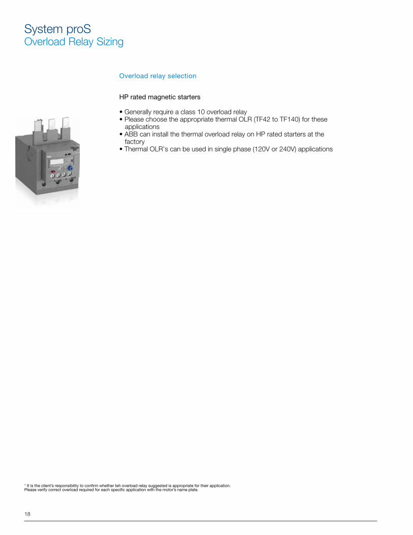
System proSOverload Relay Sizing
* It is the client’s responsibility to confirm whether teh overload relay suggested is appropriate for their application.Please verify correct overload required for each specific application with the motor’s name plate.
Overload relay selection
HP rated magnetic starters
• Generally require a class 10 overload relay• Please choose the appropriate thermal OLR (TF42 to TF140) for these applications• ABB can install the thermal overload relay on HP rated starters at the factory• Thermal OLR’s can be used in single phase (120V or 240V) applications
19
System proSPilot Device Kits for D.O.L. Starters
Customer or factory installed pilot device kits for D.O.L starters
Pilot Light
# of Devices
DescriptionNameplate Language
Nameplate TextSuffix for factory
installation
CatalogNumber
130V 1 Pilot Light English ON G PS-PL
130V 3 Push buttons + Pilot light English START / STOP / ON B PS-SSI
130V 2 2 Position Switch + Pilot Light English OFF-ON / ON D PS-SL2I
130V 2 2 Position Keyed Switch + Pilot light English OFF-ON / ON XB PS-SL2KI
130V 2 3 Position Switch + Pilot Light English HAND-OFF-AUTO / ON F PS-SL3I
130V 2 3 Position Keyed Switch + Pilot light English HAND-OFF-AUTO / ON XD PS-SL3KI
24V 1 Pilot Light English ON G PS-PLF
24V 3 Push buttons + Pilot light English START / STOP / ON B PS-SSIF
24V 2 2 Position Switch + Pilot Light English OFF-ON / ON D PS-SL2IF
24V 2 2 Position Keyed Switch + Pilot light English OFF-ON / ON XB PS-SL2KIF
24V 2 3 Position Switch + Pilot Light English HAND-OFF-AUTO / ON F PS-SL3IF
24V 2 3 Position Keyed Switch + Pilot light English HAND-OFF-AUTO / ON XD PS-SL3KIF
-- 2 Push buttons English START / STOP A PS-SS
-- 2 Push buttons English START / EMERGENCY STOP Q PS-SE
-- 1 2 Position Switch English OFF-ON C PS-SL2
-- 1 2 Position Keyed Switch English OFF-ON XA PS-SL2K
-- 1 3 Position Switch English HAND-OFF-AUTO E PS-SL3
-- 1 3 Position Keyed Switch English HAND-OFF-AUTO XC PS-SL3K
System proS, Pilot Device kits
Pilot Devices kits
Type Nameplate Suffix Catalogue ListDOL OFF-ON C PS-SL2DOL HAND-OFF-AUTO E PS-SL3DOL ON G PS-PL
One DOL HORS-EN K PS-SL2-FOperator DOL MAN-HORS-AUTO M PS-SL3-F
DOL EN SERVICE P PS-PL-F
REV FOR-OFF-REV B PS-SL3R
REV AVANT-HORS-ARR. E PS-SL3R-F2 S SLOW-OFF-FAST B PS-SL3F2 S LENT-HORS-RAPIDE E PS-SL3F-F
DOL START / STOP A PS-SSDOL OFF-ON / ON D PS-SL2I
Two DOL HAND-OFF-AUTO / ON F PS-SL3IOperators DOL MARCHE / ARRET H PS-SS-F
DOL HORS-EN / EN SERVICE L PS-SL2I-FDOL MAN-HORS-AUTO / ON N PS-SL3I-FDOL START / STOP / ON B PS-SSIDOL MARCHE / ARRET / EN SERVICE H PS-SSI-FREV FORWARD-REVERSE-STOP A PS-FRSREV FOR-OFF-REV / FORWARD / REVERSE C PS-SL3RI
Three REV AVANT-ARRIERE-ARRET D PS-FRS-FOperators REV AVANT-HORS-ARR. / AVANT / ARRIERE F PS-SL3RI-F
2 S FAST-SLOW-STOP A PS-FSO
2 S SLOW-OFF-FAST / SLOW / FAST B PS-SL3F
2 S RAPIDE-LENT-ARRET D PS-FSO-F
2 S LENT-HORS-RAPIDE / EN SERVICE E PS-SL3F-F
2 Position Switch + Pilot Light
Push buttons
3 Position Switch + Pilot Lights
3 Position Switch + Pilot LightsPush buttons
Push buttons + Pilot lightPush buttons + Pilot light
3 Position Switch + Pilot LightPush buttons
2 Position Switch + Pilot Light
Push buttons
3 Position Switch + Pilot Light
3 Position Switch + Pilot Light
3 Position Switch + Pilot Lights
Push buttons
Pilot Light
3 Position Switch
3 Position Switch3 Position Switch3 Position Switch
Push buttons
Description2 Position Switch3 Position Switch
Pilot Light2 Position Switch3 Position Switch
20
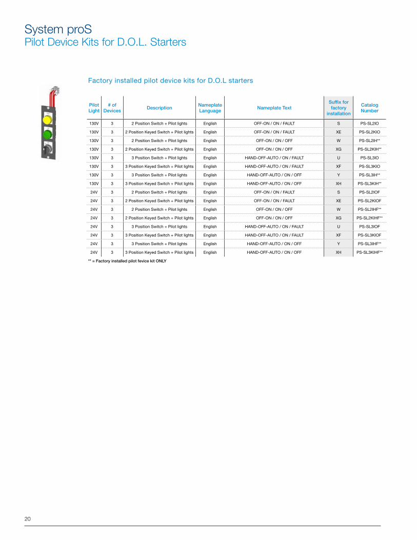
System proSPilot Device Kits for D.O.L. Starters
Factory installed pilot device kits for D.O.L starters
Pilot Light
# of Devices
DescriptionNameplate Language
Nameplate TextSuffix for factory
installation
CatalogNumber
130V 3 2 Position Switch + Pilot lights English OFF-ON / ON / FAULT S PS-SL2IO
130V 3 2 Position Keyed Switch + Pilot lights English OFF-ON / ON / FAULT XE PS-SL2KIO
130V 3 2 Position Switch + Pilot lights English OFF-ON / ON / OFF W PS-SL2IH**
130V 3 2 Position Keyed Switch + Pilot lights English OFF-ON / ON / OFF XG PS-SL2KIH**
130V 3 3 Position Switch + Pilot lights English HAND-OFF-AUTO / ON / FAULT U PS-SL3IO
130V 3 3 Position Keyed Switch + Pilot lights English HAND-OFF-AUTO / ON / FAULT XF PS-SL3KIO
130V 3 3 Position Switch + Pilot lights English HAND-OFF-AUTO / ON / OFF Y PS-SL3IH**
130V 3 3 Position Keyed Switch + Pilot lights English HAND-OFF-AUTO / ON / OFF XH PS-SL3KIH**
24V 3 2 Position Switch + Pilot lights English OFF-ON / ON / FAULT S PS-SL2IOF
24V 3 2 Position Keyed Switch + Pilot lights English OFF-ON / ON / FAULT XE PS-SL2KIOF
24V 3 2 Position Switch + Pilot lights English OFF-ON / ON / OFF W PS-SL2IHF**
24V 3 2 Position Keyed Switch + Pilot lights English OFF-ON / ON / OFF XG PS-SL2KIHF**
24V 3 3 Position Switch + Pilot lights English HAND-OFF-AUTO / ON / FAULT U PS-SL3IOF
24V 3 3 Position Keyed Switch + Pilot lights English HAND-OFF-AUTO / ON / FAULT XF PS-SL3KIOF
24V 3 3 Position Switch + Pilot lights English HAND-OFF-AUTO / ON / OFF Y PS-SL3IHF**
24V 3 3 Position Keyed Switch + Pilot lights English HAND-OFF-AUTO / ON / OFF XH PS-SL3KIHF**
** = Factory installed pilot fevice kit ONLY
21
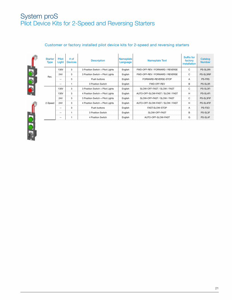
System proSPilot Device Kits for 2-Speed and Reversing Starters
Customer or factory installed pilot device kits for 2-speed and reversing starters
Starter Type
Pilot Light
# of Devices
DescriptionNameplate Language
Nameplate TextSuffix for factory
installation
CatalogNumber
Rev.
130V 3 3 Position Switch + Pilot Lights English FWD-OFF-REV / FORWARD / REVERSE C PS-SL3RI
24V 3 3 Position Switch + Pilot Lights English FWD-OFF-REV / FORWARD / REVERSE C PS-SL3RIF
-- 3 Push buttons English FORWARD-REVERSE-STOP A PS-FRS
-- 1 3 Position Switch English FWD-OFF-REV B PS-SL3R
2-Speed
130V 3 3 Position Switch + Pilot Lights English SLOW-OFF-FAST / SLOW / FAST C PS-SL3FI
130V 3 4 Position Switch + Pilot Lights English AUTO-OFF-SLOW-FAST / SLOW / FAST H PS-SL4FI
24V 3 3 Position Switch + Pilot Lights English SLOW-OFF-FAST / SLOW / FAST C PS-SL3FIF
24V 3 4 Position Switch + Pilot Lights English AUTO-OFF-SLOW-FAST / SLOW / FAST H PS-SL4FIF
-- 3 Push buttons English FAST-SLOW-STOP A PS-FSO
-- 1 3 Position Switch English SLOW-OFF-FAST B PS-SL3F
-- 1 4 Position Switch English AUTO-OFF-SLOW-FAST G PS-SL4F
22
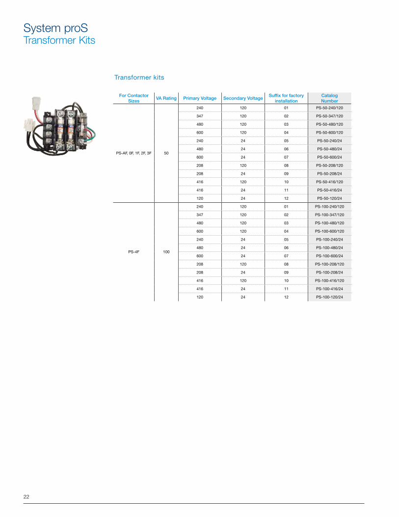
System proSTransformer Kits
Transformer kits
For Contactor Sizes
VA Rating Primary Voltage Secondary VoltageSuffix for factory
installationCatalog Number
PS-AF, 0F, 1F, 2F, 3F 50
240 120 01 PS-50-240/120
347 120 02 PS-50-347/120
480 120 03 PS-50-480/120
600 120 04 PS-50-600/120
240 24 05 PS-50-240/24
480 24 06 PS-50-480/24
600 24 07 PS-50-600/24
208 120 08 PS-50-208/120
208 24 09 PS-50-208/24
416 120 10 PS-50-416/120
416 24 11 PS-50-416/24
120 24 12 PS-50-120/24
PS-4F 100
240 120 01 PS-100-240/120
347 120 02 PS-100-347/120
480 120 03 PS-100-480/120
600 120 04 PS-100-600/120
240 24 05 PS-100-240/24
480 24 06 PS-100-480/24
600 24 07 PS-100-600/24
208 120 08 PS-100-208/120
208 24 09 PS-100-208/24
416 120 10 PS-100-416/120
416 24 11 PS-100-416/24
120 24 12 PS-100-120/24
23
System proSTechnical Data
Standard selection for Non-combination StartersTable #1
ProSStarters
Main Protection
ContactorMaximum overload
CombinationkA
AC1 AC3 Single phase (HP) Three Phases (HP)
600V 600V 120V 208V 240V 208V 240V 480V 600V
PS-AF_X... N/A AF09 TF42-16 5 25 Amp 9 Amp 0.75 HP 1 HP 1.5 HP 2 HP 2 HP 5 HP 7.5 HP
PS-0F_X... N/A AF16 TF42-24 5 30 Amp 17 Amp 1.5 HP 2 HP 3 HP 5 HP 5 HP 10 HP 15 HP
PS-1F_X... N/A AF30 TF42-35 5 50 Amp 27 Amp 2 HP 3 HP 5 HP 10 HP 10 HP 20 HP 25 HP
PS-2F_X... N/A AF52 TF65-60 5 80 Amp 52 Amp 3 HP 7.5 HP 10 HP 15 HP 20 HP 40 HP 50 HP
PS-3F_X... N/A AF80 TF96-87 10 105 Amp 77 Amp 7.5 HP 15 HP 15 HP 25 HP 30 HP 60 HP 75 HP
PS-4F_X... N/A AF140 TF140DU-142 10 200 Amp 125 Amp - - - 40 HP 50 HP 100 HP 125 HP
Standard cable range for Non-combination StartersTable #1a
HP ProSStarters
Contactor Incoming lugs
PS-AF_X... AF09 2 x (#16AWG - #10AWG)
PS-0F_X... AF16 2 x (#16AWG - #10AWG)
PS-1F_X... AF30 2 x (#14AWG - #8AWG)
PS-2F_X... AF52 2 x (#10AWG - #2AWG)
PS-3F_X... AF80 2 x (#6AWG - #1AWG)
PS-4F_X... AF140 2 x (#6AWG - #3/0AWG)
Standard selection for Combination Starters (Disconnect Switches)Table #2
ProSStarters
Main Protection
ContactorMaximum overload
CombinationkA
AC1 AC3 Single phase (HP) Three Phases (HP)
600V 600V 120V 208V 240V 208V 240V 480V 600V
PS-AF_N... OT30F3 AF09 TF42-16 5 25 Amp 9 Amp 0.75 HP 1 HP 1.5 HP 2 HP 2 HP 5 HP 7.5 HP
PS-0F_N... OT30F3 AF16 TF42-24 5 30 Amp 17 Amp 1.5 HP 2 HP 3 HP 5 HP 5 HP 10 HP 15 HP
PS-1F_N... OT60F3 AF30 TF42-35 5 50 Amp 27 Amp 2 HP 3 HP 5 HP 10 HP 10 HP 20 HP 25 HP
PS-2F_N... OT100F3 AF52 TF65-60 5 80 Amp 52 Amp 3 HP 7.5 HP 10 HP 15 HP 20 HP 40 HP 50 HP
PS-3F_N... OT200U12 AF80 TF96-87 10 105 Amp 77 Amp 7.5 HP 15 HP 15 HP 25 HP 30 HP 60 HP 75 HP
PS-4F_N... OT200U12 AF140 TF140DU-142 10 200 Amp 125 Amp - - - 40 HP 50 HP 100 HP 125 HP
Standard cable range for Combination Starters (Disconnect Switches)Table #2a
HP ProSStarters
DisconnectSwitch
Incoming lugs
PS-AF_N... OT30F3 1 x (#14AWG - #4AWG)
PS-0F_N... OT30F3 1 x (#14AWG - #4AWG)
PS-1F_N... OT60F3 1 x (#14AWG - #4AWG)
PS-2F_N... OT100F3 1 x (#8AWG - #1/0AWG)
PS-3F_N... OT200U12 1 x (#4AWG - #300MCM)
PS-4F_N... OT200U12 1 x (#4AWG - #300MCM)
24
System proSTechnical Data
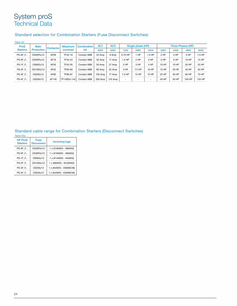
Standard selection for Combination Starters (Fuse Disconnect Switches)
Table #3
ProSStarters
Main Protection
ContactorMaximum overload
CombinationkA
AC1 AC3 Single phase (HP) Three Phases (HP)
600V 600V 120V 208V 240V 208V 240V 480V 600V
PS-AF_F... OS30FAJ12 AF09 TF42-16 Contact ABB 25 Amp 9 Amp 0.75 HP 1 HP 1.5 HP 2 HP 2 HP 5 HP 7.5 HP
PS-0F_F... OS30FAJ12 AF16 TF42-24 Contact ABB 30 Amp 17 Amp 1.5 HP 2 HP 3 HP 5 HP 5 HP 10 HP 15 HP
PS-1F_F... OS60GJ12 AF30 TF42-35 Contact ABB 50 Amp 27 Amp 2 HP 3 HP 5 HP 10 HP 10 HP 20 HP 25 HP
PS-2F_F... OS100GJ12 AF52 TF65-60 Contact ABB 80 Amp 52 Amp 3 HP 7.5 HP 10 HP 15 HP 20 HP 40 HP 50 HP
PS-3F_F... OS200J12 AF80 TF96-87 Contact ABB 105 Amp 77 Amp 7.5 HP 15 HP 15 HP 25 HP 30 HP 60 HP 75 HP
PS-4F_F... OS200J12 AF140 TF140DU-142 Contact ABB 200 Amp 125 Amp - - - 40 HP 50 HP 100 HP 125 HP
Standard cable range for Combination Starters (Disconnect Switches)Table #2a
HP ProSStarters
Fuse Disconnect
Incoming lugs
PS-AF_F... OS30FAJ12 1 x (#18AWG - #8AWG)
PS-0F_F... OS30FAJ12 1 x (#18AWG - #8AWG)
PS-1F_F... OS60GJ12 1 x (#14AWG - #4AWG)
PS-2F_F... OS100GJ12 1 x (#8AWG - #2/0AWG)
PS-3F_F... OS200J12 1 x (#4AWG - #300MCM)
PS-4F_F... OS200J12 1 x (#4AWG - #300MCM)
25
System proSTechnical Data
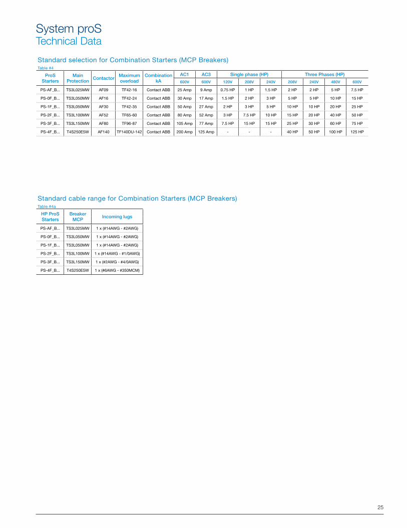
Standard selection for Combination Starters (MCP Breakers)Table #4
ProSStarters
Main Protection
ContactorMaximum overload
CombinationkA
AC1 AC3 Single phase (HP) Three Phases (HP)
600V 600V 120V 208V 240V 208V 240V 480V 600V
PS-AF_B... TS3L025MW AF09 TF42-16 Contact ABB 25 Amp 9 Amp 0.75 HP 1 HP 1.5 HP 2 HP 2 HP 5 HP 7.5 HP
PS-0F_B... TS3L050MW AF16 TF42-24 Contact ABB 30 Amp 17 Amp 1.5 HP 2 HP 3 HP 5 HP 5 HP 10 HP 15 HP
PS-1F_B... TS3L050MW AF30 TF42-35 Contact ABB 50 Amp 27 Amp 2 HP 3 HP 5 HP 10 HP 10 HP 20 HP 25 HP
PS-2F_B... TS3L100MW AF52 TF65-60 Contact ABB 80 Amp 52 Amp 3 HP 7.5 HP 10 HP 15 HP 20 HP 40 HP 50 HP
PS-3F_B... TS3L150MW AF80 TF96-87 Contact ABB 105 Amp 77 Amp 7.5 HP 15 HP 15 HP 25 HP 30 HP 60 HP 75 HP
PS-4F_B... T4S250E5W AF140 TF140DU-142 Contact ABB 200 Amp 125 Amp - - - 40 HP 50 HP 100 HP 125 HP
Standard cable range for Combination Starters (MCP Breakers)Table #4a
HP ProSStarters
BreakerMCP
Incoming lugs
PS-AF_B... TS3L025MW 1 x (#14AWG - #2AWG)
PS-0F_B... TS3L050MW 1 x (#14AWG - #2AWG)
PS-1F_B... TS3L050MW 1 x (#14AWG - #2AWG)
PS-2F_B... TS3L100MW 1 x (#14AWG - #1/0AWG)
PS-3F_B... TS3L150MW 1 x (#2AWG - #4/0AWG)
PS-4F_B... T4S250E5W 1 x (#6AWG - #350MCM)
26
System proSTechnical Data
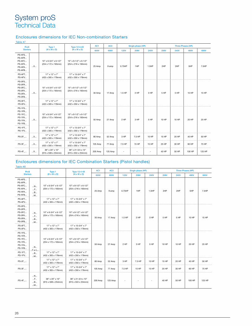
Enclosures dimensions for IEC Non-combination StartersTable #7
ProSStarters
Type 1(H x W x D)
Type 12-4-4X(H x W x D)
AC1 AC3 Single phase (HP) Three Phases (HP)
600V 600V 120V 208V 240V 208V 240V 480V 600V
PS-AFS...
PS-AFR...
PS-AFC...
PS-AFK...
PS-AFA...
PS-AFB...
...X...
10” x 6-3/4” x 6-1/2”
(254 x 172 x 165mm)
10” x 8-1/2” x 6-1/2”
(254 x 216 x 165mm)25 Amp 9 amp 0.75HP 1HP 1.5HP 2HP 2HP 5HP 7.5HP
PS-AFT...
PS-AFV...
17” x 12” x 7”
(432 x 305 x 178mm)
17” x 13-3/4” x 7”
(432 x 350 x 178mm)
PS-0FS...
PS-0FR...
PS-0FC...
PS-0FK...
PS-0FA...
PS-0FB...
...X...
10” x 6-3/4” x 6-1/2”
(254 x 172 x 165mm)
10” x 8-1/2” x 6-1/2”
(254 x 216 x 165mm)30 Amp 17 Amp 1.5 HP 2 HP 3 HP 5 HP 5 HP 10 HP 15 HP
PS-0FT...
PS-0FV...
17” x 12” x 7”
(432 x 305 x 178mm)
17” x 13-3/4” x 7”
(432 x 350 x 178mm)
PS-1FS...
PS-1FR...
PS-1FC...
PS-1FK...
PS-1FA...
PS-1FB...
...X...
10” x 6-3/4” x 6-1/2”
(254 x 172 x 165mm)
10” x 8-1/2” x 6-1/2”
(254 x 216 x 165mm)50 Amp 27 Amp 2 HP 3 HP 5 HP 10 HP 10 HP 20 HP 25 HP
PS-1FT...
PS-1FV...
17” x 12” x 7”
(432 x 305 x 178mm)
17” x 13-3/4” x 7”
(432 x 350 x 178mm)
PS-2F_... ...X...17” x 12” x 7”
(432 x 305 x 178mm)
17” x 13-3/4” x 7”
(432 x 350 x 178mm)80 Amp 52 Amp 3 HP 7.5 HP 10 HP 15 HP 20 HP 40 HP 50 HP
PS-3F_... ...X...17” x 12” x 7”
(432 x 305 x 178mm)
17” x 13-3/4” x 7”
(432 x 350 x 178mm)105 Amp 77 Amp 7.5 HP 15 HP 15 HP 25 HP 30 HP 60 HP 75 HP
PS-4F_... ...X...36” x 20” x 10”
(915 x 508 x 254mm)
36” x 21-3/4 x 10”
(915 x 553 x 254mm)200 Amp 125 Amp - - - 40 HP 50 HP 100 HP 125 HP
Enclosures dimensions for IEC Combination Starters (Pistol handles)Table #8
ProSStarters
Type 1(H x W x D)
Type 12-4-4X(H x W x D)
AC1 AC3 Single phase (HP) Three Phases (HP)
600V 600V 120V 208V 240V 208V 240V 480V 600V
PS-AFS...
PS-AFR...
PS-AFC...
PS-AFK...
PS-AFA...
PS-AFB...
...N...
...F...
...B...
...M...
10” x 6-3/4” x 6-1/2”
(254 x 172 x 165mm)
10” x 8-1/2” x 6-1/2”
(254 x 216 x 165mm)25 Amp 9 amp 0.75HP 1HP 1.5HP 2HP 2HP 5HP 7.5HP
PS-AFT...
PS-AFV...
17” x 12” x 7”
(432 x 305 x 178mm)
17” x 13-3/4” x 7”
(432 x 350 x 178mm)
PS-0FS...
PS-0FR...
PS-0FC...
PS-0FK...
PS-0FA...
PS-0FB...
...N...
...F...
...B...
...M...
10” x 6-3/4” x 6-1/2”
(254 x 172 x 165mm)
10” x 8-1/2” x 6-1/2”
(254 x 216 x 165mm)30 Amp 17 Amp 1.5 HP 2 HP 3 HP 5 HP 5 HP 10 HP 15 HP
PS-0FT...
PS-0FV...
17” x 12” x 7”
(432 x 305 x 178mm)
17” x 13-3/4” x 7”
(432 x 350 x 178mm)
PS-1FS...
PS-1FR...
PS-1FC...
PS-1FK...
PS-1FA...
PS-1FB... ...N...
...F or L...
...B...
...M...
10” x 6-3/4” x 6-1/2”
(254 x 172 x 165mm)
10” x 8-1/2” x 6-1/2”
(254 x 216 x 165mm)50 Amp 27 Amp 2 HP 3 HP 5 HP 10 HP 10 HP 20 HP 25 HP
PS-1FT...
PS-1FV...
17” x 12” x 7”
(432 x 305 x 178mm)
17” x 13-3/4” x 7”
(432 x 350 x 178mm)
PS-2F_...17” x 12” x 7”
(432 x 305 x 178mm)
17” x 13-3/4” x 7”
(432 x 350 x 178mm)80 Amp 52 Amp 3 HP 7.5 HP 10 HP 15 HP 20 HP 40 HP 50 HP
PS-3F_...17” x 12” x 7”
(432 x 305 x 178mm)
17” x 13-3/4” x 7”
(432 x 350 x 178mm)105 Amp 77 Amp 7.5 HP 15 HP 15 HP 25 HP 30 HP 60 HP 75 HP
PS-4F_...
...N...
...F...
...B...
...M...
36” x 20” x 10”
(915 x 508 x 254mm)
36” x 21-3/4 x 10”
(915 x 553 x 254mm)200 Amp 125 Amp - - - 40 HP 50 HP 100 HP 125 HP
27
System proSTechnical Data
Standard cable range for Overload Relays
Table#11 & 12
Suffix Code
Thermal CatalogNumber
Current Setting Range
Cable Range
A TF42-0.13 0.10 ... 0.13 2 x (#18AWG - #10AWG)
B TF42-0.17 0.13 ... 0.17 2 x (#18AWG - #10AWG)
C TF42-0.23 0.17 ... 0.23 2 x (#18AWG - #10AWG)
D TF42-0.31 0.23 ... 0.31 2 x (#18AWG - #10AWG)
E TF42-0.41 0.31 ... 0.41 2 x (#18AWG - #10AWG)
F TF42-0.55 0.41 ... 0.55 2 x (#18AWG - #10AWG)
G TF42-0.74 0.55 ... 0.74 2 x (#18AWG - #10AWG)
H TF42-1.0 0.74 ... 1.0 2 x (#18AWG - #10AWG)
J TF42-1.3 1.0 ... 1.3 2 x (#18AWG - #10AWG)
K TF42-1.7 1.3 ... 1.7 2 x (#18AWG - #10AWG)
L TF42-2.3 1.7 ... 2.3 2 x (#18AWG - #10AWG)
M TF42-3.1 2.3 ... 3.1 2 x (#18AWG - #10AWG)
N TF42-4.2 3.1 ... 4.2 2 x (#18AWG - #10AWG)
P TF42-5.7 4.2 ... 5.7 2 x (#18AWG - #10AWG)
Q TF42-7.6 5.7 ... 7.6 2 x (#18AWG - #10AWG)
R TF42-10 7.6 ... 10 2 x (#18AWG - #10AWG)
S TF42-13 10 ... 13 2 x (#18AWG - #10AWG)
T TF42-16 13 ... 16 2 x (#18AWG - #10AWG)
U TF42-20 16 ... 20 2 x (#14AWG - #6AWG)
V TF42-24 20 ... 24 2 x (#14AWG - #6AWG)
W TF42-29 24 ... 29 2 x (#14AWG - #6AWG)
X TF42-35 29 ... 35 2 x (#14AWG - #6AWG)
A TF65-28 22 … 28 2 x (#12AWG - #6AWG)
B TF65-33 25 … 33 2 x (#12AWG - #6AWG)
C TF65-40 30 … 40 2 x (#12AWG - #6AWG)
D TF65-47 36 … 47 2 x (#12AWG - #6AWG)
E TF65-53 44 … 53 2 x (#12AWG - #6AWG)
F TF65-60 50 … 60 2 x (#12AWG - #6AWG)
G TF65-67 57 … 67 2 x (#12AWG - #6AWG)
A TF96-51 40 … 51 2 x (#8AWG - #3AWG)
B TF96-60 48 … 60 2 x (#8AWG - #3AWG)
C TF96-68 57 … 68 2 x (#8AWG - #3AWG)
D TF96-78 65 … 78 2 x (#8AWG - #3AWG)
E TF96-87 75 … 87 2 x (#8AWG - #3AWG)
F TF96-96 84 … 96 2 x (#8AWG - #3AWG)
A TF140DU-90 66 … 90 2 x (#6AWG - #2/0AWG)
B TF140DU-110 80 … 110 2 x (#6AWG - #2/0AWG)
C TF140DU-135 100 … 135 2 x (#6AWG - #2/0AWG)
D TF140DU-142 110 … 142 2 x (#6AWG - #2/0AWG)
28
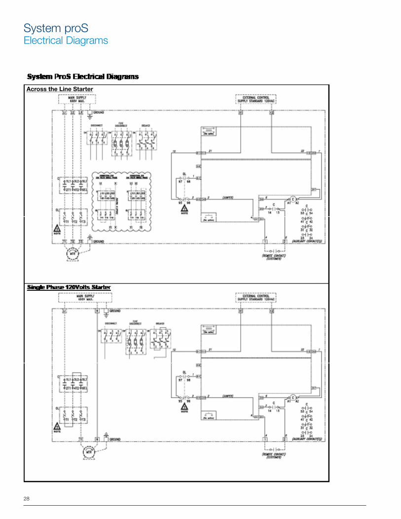
System proSElectrical Diagrams
1
1
Across the Line Starter
29
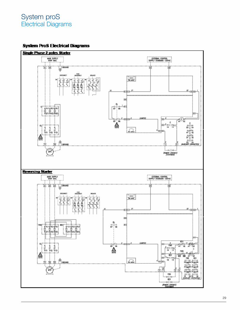
System proSElectrical Diagrams
1
30
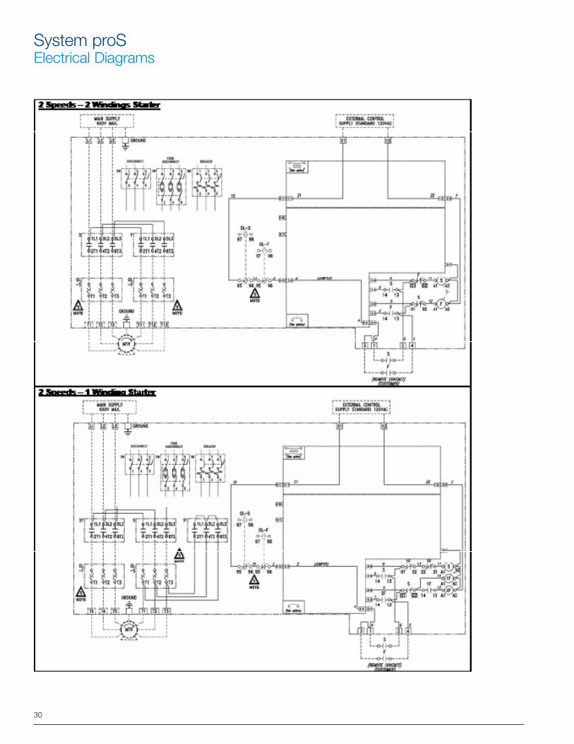
System proSElectrical Diagrams
31
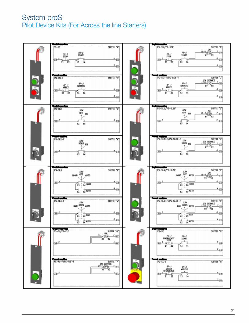
System proSPilot Device Kits (For Across the line Starters)
32
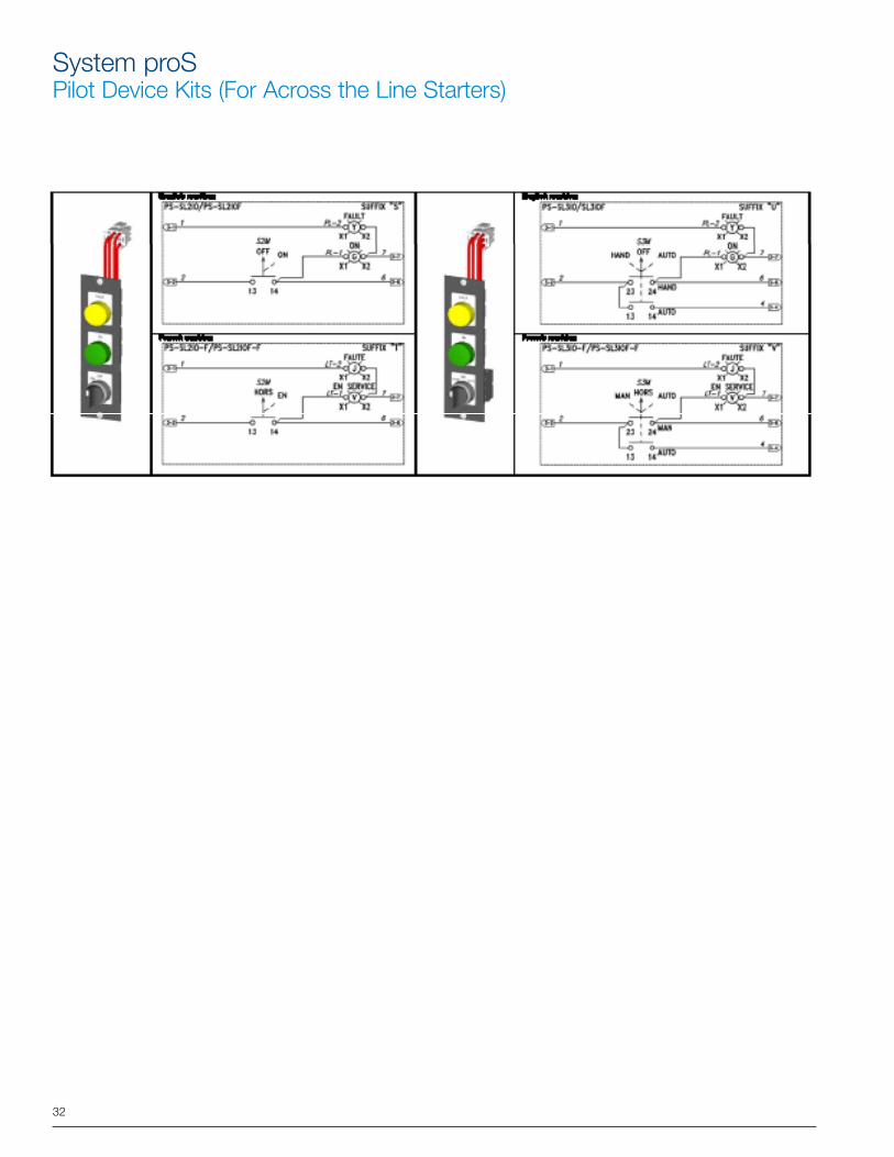
System proSPilot Device Kits (For Across the Line Starters)
33
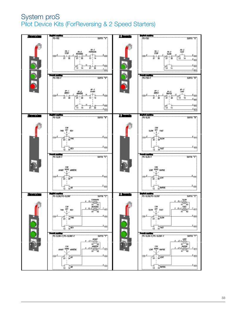
System proSPilot Device Kits (ForReversing & 2 Speed Starters)
34
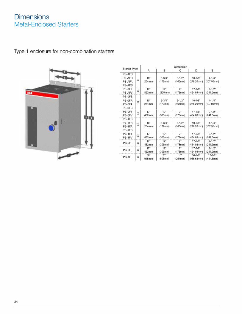
DimensionsMetal-Enclosed Starters
Starter TypeDimension
A B C D EPS-AFS
X10”
(254mm)6-3/4”
(172mm)6-1/2”
(165mm)10-7/8”
(276.26mm)4-1/4”
(107.95mm)PS-AFRPS-AFAPS-AFBPS-AFT
X17”
(432mm)12”
(305mm)7”
(178mm)17-7/8”
(454.03mm)9-1/2”
(241.3mm)PS-AFVPS-0FS
X10”
(254mm)6-3/4”
(172mm)6-1/2”
(165mm)10-7/8”
(276.26mm)4-1/4”
(107.95mm)PS-0FRPS-0FAPS-0FBPS-0FT
X17”
(432mm)12”
(305mm)7”
(178mm)17-7/8”
(454.03mm)9-1/2”
(241.3mm)PS-0FVPS-1FS
X10”
(254mm)6-3/4”
(172mm)6-1/2”
(165mm)10-7/8”
(276.26mm)4-1/4”
(107.95mm)PS-1FRPS-1FAPS-1FBPS-1FT
X17”
(432mm)12”
(305mm)7”
(178mm)17-7/8”
(454.03mm)9-1/2”
(241.3mm)PS-1FV
PS-2F_ X17”
(432mm)12”
(305mm)7”
(178mm)17-7/8”
(454.03mm)9-1/2”
(241.3mm)
PS-3F_ X17”
(432mm)12”
(305mm)7”
(178mm)17-7/8”
(454.03mm)9-1/2”
(241.3mm)
PS-4F_ X36”
(915mm)20”
(508mm)10”
(254mm)36-7/8”
(936.63mm)17-1/2”
(444.5mm)
Type 1 enclosure for non-combination starters
35
Starter TypeDimension
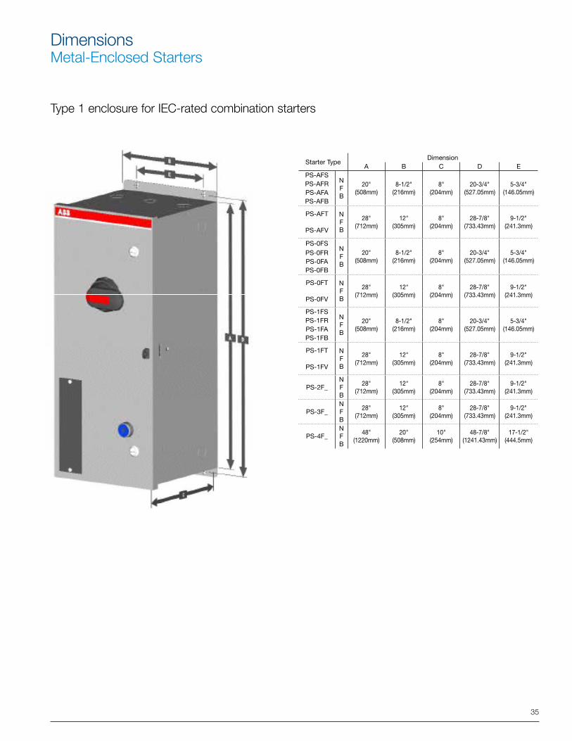
A B C D EPS-AFS
NFB
20" (508mm)
8-1/2" (216mm)
8" (204mm)
20-3/4" (527.05mm)
5-3/4" (146.05mm)
PS-AFRPS-AFAPS-AFB
PS-AFT NFB
28" (712mm)
12" (305mm)
8" (204mm)
28-7/8" (733.43mm)
9-1/2" (241.3mm)
PS-AFV
PS-0FSNFB
20" (508mm)
8-1/2" (216mm)
8" (204mm)
20-3/4" (527.05mm)
5-3/4" (146.05mm)
PS-0FRPS-0FAPS-0FB
PS-0FT NFB
28" (712mm)
12" (305mm)
8" (204mm)
28-7/8" (733.43mm)
9-1/2" (241.3mm)
PS-0FV
PS-1FSNFB
20" (508mm)
8-1/2" (216mm)
8" (204mm)
20-3/4" (527.05mm)
5-3/4" (146.05mm)
PS-1FRPS-1FAPS-1FB
PS-1FT NFB
28" (712mm)
12" (305mm)
8" (204mm)
28-7/8" (733.43mm)
9-1/2" (241.3mm)
PS-1FV
PS-2F_NFB
28" (712mm)
12" (305mm)
8" (204mm)
28-7/8" (733.43mm)
9-1/2" (241.3mm)
PS-3F_NFB
28" (712mm)
12" (305mm)
8" (204mm)
28-7/8" (733.43mm)
9-1/2" (241.3mm)
PS-4F_NFB
48" (1220mm)
20" (508mm)
10" (254mm)
48-7/8" (1241.43mm)
17-1/2" (444.5mm)
Type 1 enclosure for IEC-rated combination starters
DimensionsMetal-Enclosed Starters
36
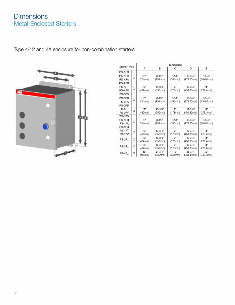
Starter TypeDimension
A B C D EPS-AFS
X10"
(254mm)8-1/2"
(216mm)6-1/2"
(165mm)10-3/4"
(273.05mm)5-3/4"
(146.05mm)PS-AFRPS-AFAPS-AFBPS-AFT
X17”
(432mm)13-3/4”
(350mm)7”
(178mm)17-3/4”
(450.85mm)11”
(279.4mm)PS-AFVPS-0FS
X10"
(254mm)8-1/2"
(216mm)6-1/2"
(165mm)10-3/4"
(273.05mm)5-3/4"
(146.05mm)PS-0FRPS-0FAPS-0FBPS-0FT
X17”
(432mm)13-3/4”
(350mm)7”
(178mm)17-3/4”
(450.85mm)11”
(279.4mm)PS-0FVPS-1FS
X10"
(254mm)8-1/2"
(216mm)6-1/2"
(165mm)10-3/4"
(273.05mm)5-3/4"
(146.05mm)PS-1FRPS-1FAPS-1FBPS-1FT
X17”
(432mm)13-3/4”
(350mm)7”
(178mm)17-3/4”
(450.85mm)11”
(279.4mm)PS-1FV
PS-2F_ X17”
(432mm)13-3/4”
(350mm)7”
(178mm)17-3/4”
(450.85mm)11”
(279.4mm)
PS-3F_ X17”
(432mm)13-3/4”
(350mm)7”
(178mm)17-3/4”
(450.85mm)11”
(279.4mm)
PS-4F_ X36”
(915mm)21-3/4” (535mm)
10” (254mm)
36-3/4” (933.45mm)
19” (482.6mm)
Type 4/12 and 4X enclosure for non-combination starters
DimensionsMetal-Enclosed Starters
37
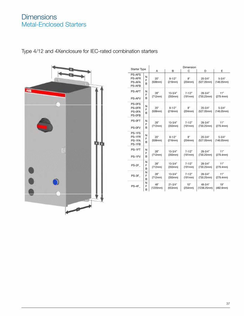
Starter TypeDimension
A B C D EPS-AFS
NFB
20" (508mm)
8-1/2" (216mm)
8" (204mm)
20-3/4" (527.05mm)
5-3/4" (146.05mm)
PS-AFRPS-AFAPS-AFB
PS-AFT NFB
28”(712mm)
13-3/4” (350mm)
7-1/2” (191mm)
28-3/4” (730.25mm)
11” (279.4mm)
PS-AFV
PS-0FSNFB
20" (508mm)
8-1/2" (216mm)
8" (204mm)
20-3/4" (527.05mm)
5-3/4" (146.05mm)
PS-0FRPS-0FAPS-0FB
PS-0FT NFB
28”(712mm)
13-3/4” (350mm)
7-1/2” (191mm)
28-3/4” (730.25mm)
11” (279.4mm)
PS-0FV
PS-1FSNFB
20" (508mm)
8-1/2" (216mm)
8" (204mm)
20-3/4" (527.05mm)
5-3/4" (146.05mm)
PS-1FRPS-1FAPS-1FB
PS-1FT NFB
28”(712mm)
13-3/4” (350mm)
7-1/2” (191mm)
28-3/4” (730.25mm)
11” (279.4mm)
PS-1FV
PS-2F_NFB
28”(712mm)
13-3/4” (350mm)
7-1/2” (191mm)
28-3/4” (730.25mm)
11” (279.4mm)
PS-3F_NFB
28”(712mm)
13-3/4” (350mm)
7-1/2” (191mm)
28-3/4” (730.25mm)
11” (279.4mm)
PS-4F_NFB
48" (1220mm)
21-3/4" (553mm)
10" (254mm)
48-3/4" (1238.25mm)
19" (482.6mm)
Type 4/12 and 4Xenclosure for IEC-rated combination starters
DimensionsMetal-Enclosed Starters
![Reversing and Malware Analysis Training Articles [2012] . cracking/Reversing... · Reversing and Malware Analysis Training Articles ... Step 1: Start with what you ... Reversing and](https://static.fdocuments.net/doc/165x107/5ab905fd7f8b9ac10d8db0ab/reversing-and-malware-analysis-training-articles-2012-crackingreversingreversing.jpg)