SYSTEM FOR AUTOMATIC DETECTION OF DISTORTED SCENES …
6
SYSTEM FOR AUTOMATIC DETECTION OF DISTORTED SCENES IN STEREO VIDEO Alexander Voronov, Alexey Borisov, Dmitriy Vatolin Graphics & Media Lab, Moscow State University {avoronov, aborisov, dmitriy}@graphics.cs.msu.ru ABSTRACT In this paper we describe our methods for estimating stereo video quality and its suitability for certain displays and pro- jectors. The first issue we investigate is that not every 3D video can be viewed comfortably on a given 3D display ow- ing to its particular features, especially parallax. The second issue is the correspondence between left and right views. Because of the complexity of calibrating and synchronizing video capture devices, some mismatch problems and arti- facts may appear. These artifacts can affect the 3D viewing experience. Our goal is to detect and, in some cases, suggest how they can be suppressed. We demonstrate our current results and describe directions for further development and improvement of the implemented techniques. 1. INTRODUCTION Nowadays 3D video is growing in popularity. The amount of available 3D video content and the number of different 3D displays and projectors are growing. The first problem we encounter is that not every 3D video can be viewed com- fortably using a given device. Different devices have dif- ferent comfortable parallax ranges, and (for example) 3D effects in videos prepared for a large screen will be unno- ticeable on home displays. Thus, we need a tool to estimate stereo video parallax, and we must also determine what par- allax is suitable for a particular device. A variety of techniques are available for 3D video cre- ation. Video can be captured by a stereo camera, converted from traditional 2D format or rendered from a 3D model. Sometimes combinations of these approaches are used. When creating 3D content, new requirements arise for achieving high-quality results. Capturing video using a stereo cam- era requires precise camera settings with fine-tuned angles, and we therefore assume that the color and geometry of the pictures taken by two cameras in a stereo rig may differ slightly. Furthermore, zooming shots may be unsynchro- nized. We must control sharpness in each view; the same object must be in focus in both the left and right views. When converting from 2D format to stereoscopic 3D, processing of edges and occlusion areas is the most impor- tant consideration. With improper processing of semitrans- parent edges and thin objects, some parts of the foreground may end up stuck to the background in the resulting video. For complex boundaries or backgrounds, insufficiently ac- curate processing can produce specific jitter, which is no- ticeable in moving objects. Such problems in stereo pro- duction can spoil the experience of viewing 3D video. 2. RELATED WORK The problems described above are under active investiga- tion. We have conducted an overview of techniques for de- tecting and correcting artifacts and problems in stereo video – mostly focusing on detection. Different methods enable control and enhancement of color correspondence between views, using both a global transform for the entire frame [1] and a local transform for analyzing areas in a given frame separately [2]. These meth- ods allow us to estimate the color difference between views. Most of the works on correction of geometric distortions refer to the stereo rectification problem [3, 4] and describe calculations for parameters such as vertical parallax, tilt and vertical perspective distortion. A special method for zoom mistiming detection was suggested in [5]. To detect differ- ent sharpness levels in a stereomate, it is possible to match feature points between views, estimate blur measure [6] in the images and compare results in corresponding areas. An- other important technique is time synchronization between views. A wide variety of methods exist for solving this problem. Some of these methods match a videos 3D struc- ture in width × height × time axes on the pixel or super- pixel level [7], and some reduce the videos complexity by extracting a special trace from the sequence and then match- ing it. Examples of such traces are pixels in epipolar lines [8] and the number of points of interest in a frame [9]. Esti- mation of time desynchronization is also important because sometimes a stereo motion picture is produced from mono by time shifting one view. But if motion in the video is uneven, the parallax of the resulting stereo is unstable.
Transcript of SYSTEM FOR AUTOMATIC DETECTION OF DISTORTED SCENES …

SYSTEM FOR AUTOMATIC DETECTION OF DISTORTED SCENES IN STEREO VIDEO
Alexander Voronov, Alexey Borisov, Dmitriy Vatolin
Graphics & Media Lab, Moscow State University{avoronov, aborisov, dmitriy}@graphics.cs.msu.ru
ABSTRACT
In this paper we describe our methods for estimating stereovideo quality and its suitability for certain displays and pro-jectors. The first issue we investigate is that not every 3Dvideo can be viewed comfortably on a given 3D display ow-ing to its particular features, especially parallax. The secondissue is the correspondence between left and right views.Because of the complexity of calibrating and synchronizingvideo capture devices, some mismatch problems and arti-facts may appear. These artifacts can affect the 3D viewingexperience. Our goal is to detect and, in some cases, suggesthow they can be suppressed. We demonstrate our currentresults and describe directions for further development andimprovement of the implemented techniques.
1. INTRODUCTION
Nowadays 3D video is growing in popularity. The amountof available 3D video content and the number of different3D displays and projectors are growing. The first problemwe encounter is that not every 3D video can be viewed com-fortably using a given device. Different devices have dif-ferent comfortable parallax ranges, and (for example) 3Deffects in videos prepared for a large screen will be unno-ticeable on home displays. Thus, we need a tool to estimatestereo video parallax, and we must also determine what par-allax is suitable for a particular device.
A variety of techniques are available for 3D video cre-ation. Video can be captured by a stereo camera, convertedfrom traditional 2D format or rendered from a 3D model.Sometimes combinations of these approaches are used. Whencreating 3D content, new requirements arise for achievinghigh-quality results. Capturing video using a stereo cam-era requires precise camera settings with fine-tuned angles,and we therefore assume that the color and geometry of thepictures taken by two cameras in a stereo rig may differslightly. Furthermore, zooming shots may be unsynchro-nized. We must control sharpness in each view; the sameobject must be in focus in both the left and right views.
When converting from 2D format to stereoscopic 3D,processing of edges and occlusion areas is the most impor-tant consideration. With improper processing of semitrans-
parent edges and thin objects, some parts of the foregroundmay end up stuck to the background in the resulting video.For complex boundaries or backgrounds, insufficiently ac-curate processing can produce specific jitter, which is no-ticeable in moving objects. Such problems in stereo pro-duction can spoil the experience of viewing 3D video.
2. RELATED WORK
The problems described above are under active investiga-tion. We have conducted an overview of techniques for de-tecting and correcting artifacts and problems in stereo video– mostly focusing on detection.
Different methods enable control and enhancement ofcolor correspondence between views, using both a globaltransform for the entire frame [1] and a local transform foranalyzing areas in a given frame separately [2]. These meth-ods allow us to estimate the color difference between views.Most of the works on correction of geometric distortionsrefer to the stereo rectification problem [3, 4] and describecalculations for parameters such as vertical parallax, tilt andvertical perspective distortion. A special method for zoommistiming detection was suggested in [5]. To detect differ-ent sharpness levels in a stereomate, it is possible to matchfeature points between views, estimate blur measure [6] inthe images and compare results in corresponding areas. An-other important technique is time synchronization betweenviews. A wide variety of methods exist for solving thisproblem. Some of these methods match a videos 3D struc-ture in width × height × time axes on the pixel or super-pixel level [7], and some reduce the videos complexity byextracting a special trace from the sequence and then match-ing it. Examples of such traces are pixels in epipolar lines[8] and the number of points of interest in a frame [9]. Esti-mation of time desynchronization is also important becausesometimes a stereo motion picture is produced from monoby time shifting one view. But if motion in the video isuneven, the parallax of the resulting stereo is unstable.

3. PROPOSED METHOD
Our goal is to create a stereo video analysis tool that willcontrol the maximum parallax and automatically detect prob-lems in stereo video shots. We have thus far implementedthe following features:
• maximum parallax estimation• color distortion estimation• geometric distortion estimation
To perform matching between views we use a block-based motion estimation algorithm, which is described in[10]. This algorithm estimates motion with quarter-pixelaccuracy for block sizes of 4 × 4 to 16 × 16 pixels. One ofthe reasons for using this block-based approach is process-ing speed: block-based matching is much faster than opticalflow or point-based matching.
3.1. Maximum parallax estimation
This procedure comprises the following steps:
1. Estimation of the motion vector field between views2. Motion vector field filtering3. Estimation of the rough disparity map and distribu-
tion of depths in the frame4. Analysis of depth distribution throughout the entire
video and detection of problem shots
Filtering of the motion vector field (MVF) eliminatesoutliers, which mostly appear in uniform areas. Also, anoteworthy point is that depth artifacts are usually almostimperceptible in such uniform untextured areas, so these ar-eas don’t play an important role in the final result. Filteringof the MVF is based on the confidence measure from [11].In that work the authors estimate confidence according tothe variance in an image block, the SAD (sum of absolutedifferences) error in compensation, and the correspondencebetween the vector direction and its neighbors. This stepyields the confidence map for the MVF; this map is usedlater when calculating the depth distribution in a frame.
We estimate disparity as the horizontal component of amotion vector for a given block and then compute the dis-parity histogram for the frame; only blocks with high confi-dence are taken into account. Then we clip 5 percent of allblocks from the boundaries of the histogram and assume thefinal left- and rightmost values are the minimum and maxi-mum parallax values.
To analyze depth we plot a distribution graph that showsthe number of pixels according to the disparity in the time-line. Beforehand, we asked user to input the display sys-tem characteristics, which can clearly indicate the maxi-mum artifact-free parallax level; an example parallax mon-itoring graph is shown in Fig. 1. We then mark frames thathave a parallax exceeding a certain value.
(a) Left view (b) Right view
Fig. 3: Example of color distortion from “Avatar PandoraDiscovered” at frame 1,251. A large difference in lumi-nance between the views was detected.
3.2. Color distortion estimation
This procedure detects shots with color mismatch betweenthe left and right views. The reason of such distortions istypically in cameras. First, even for identical cameras theremay be some difference in sensor readout that yields differ-ent color tones in different views for the same object. Sec-ond, not all cameras allow manual exposure, white balancesetting or high-quality automatic correction, thus potentiallycausing differences in images’ gamma.
For each view we form three histograms (one for eachcolor plane in RGB), then we smooth them using a Gaus-sian kernel and calculate the SAD among the histograms.When this value is greater than a predefined threshold, weassume that a noticeable color distortion is present. Next weplace the estimated values in the timeline (Fig. 2); the shotsfor which our measure exceeds the acceptable threshold arevisible. Fig. 3 shows an example of a problem stereomate.
3.3. Geometric distortion estimation
This procedure enables detection of shots for which the cam-eras were inaccurately set and calibrated.
Currently we estimate vertical parallax and tilt withoutusing epipolar geometry computation or stereo rectification.Vertical parallax is estimated as the median value of they-component among all the vectors with high confidence.To estimate tilt we subtract the vertical parallax value fromeach vector; the estimate of the possible rotation angle is themedian tilt angle for each confident vector. In these calcu-lations we take into account the distance of a point from theimage center as well as its new y-coordinate.
Analysis of the estimated values in the timeline enablesdetection of problem shots (Fig. 4). A sample of visualiza-tion is shown in Fig. 5.
4. IMPLEMENTATION
The algorithm is implemented as combination of a VirtualDubfilter and a MATLAB script. The VirtualDub filter performsvideo processing and estimates different measures for each

Fig. 1: Example of parallax control graph for the movie “Pirates of the Caribbean: on Stranger Tides.” The parallax clearlydiffers from scene to scene, and a large parallax is achieved only in a small portion of scenes.
Fig. 2: Color distortion graph for “Avatar Pandora Discovered.” The locations of detected problems are marked with yellowlines.
Fig. 4: Geometric distortion graph for “Avatar Pandora Discovered.” The locations of detected problems are marked withyellow lines.
frame. The filter writes the data to a text file, and the MAT-LAB script analyzes the data and plots graphs.
5. RESULTS
To demonstrate our tool, we tested 10 trailers for new andwell-known 3D movies:
• Avatar Pandora Discovered• Pirates of the Caribbean: On Stranger Tides• Transformers 3: Dark of the Moon• Alice in Wonderland• The Priest• Resident Evil 4: Afterlife• The Smurfs• Bitwa Warszawska• Tron: The Legacy• The Chronicles of Narnia: The Voyage of the Dawn
Treader
Our analysis revealed some problems in these trailers.For the “Avatar” trailer, differences in luminance were de-tected, as Fig. 3 shows. The trailer also contains some geo-metric distortions; for example, Fig. 6 demonstrates a prob-lem frame that is a combination of captured video and com-puter rendering. The rendered parts are placed correctly, butthe captured video appears mistimed between views. Forsome shots in “Pirates of the Caribbean,” rather noticeabledifferences in color tones are apparent (Fig. 7). Other trail-ers also contain some shots with color distortions (Fig. 8).
Another interesting point is analysis of parallax controlin different movies. In “Pirates of the Caribbean” we seeappreciable 3D effect only in some scenes (specifically, inclose-up scenes), but most shots have little noticeable 3Dcharacter. For other trailers – for example, “Transformers 3”or “Bitwa Warszawska” – we can see that the depth gradingprocedure was accurately performed: parallax is adjustedfor the whole video. Fig. 9 presents graphs demonstratingdifferent strategies for depth grading. Also we can select
(a) Left view (b) Right view
(c) Geometric distortion visualization
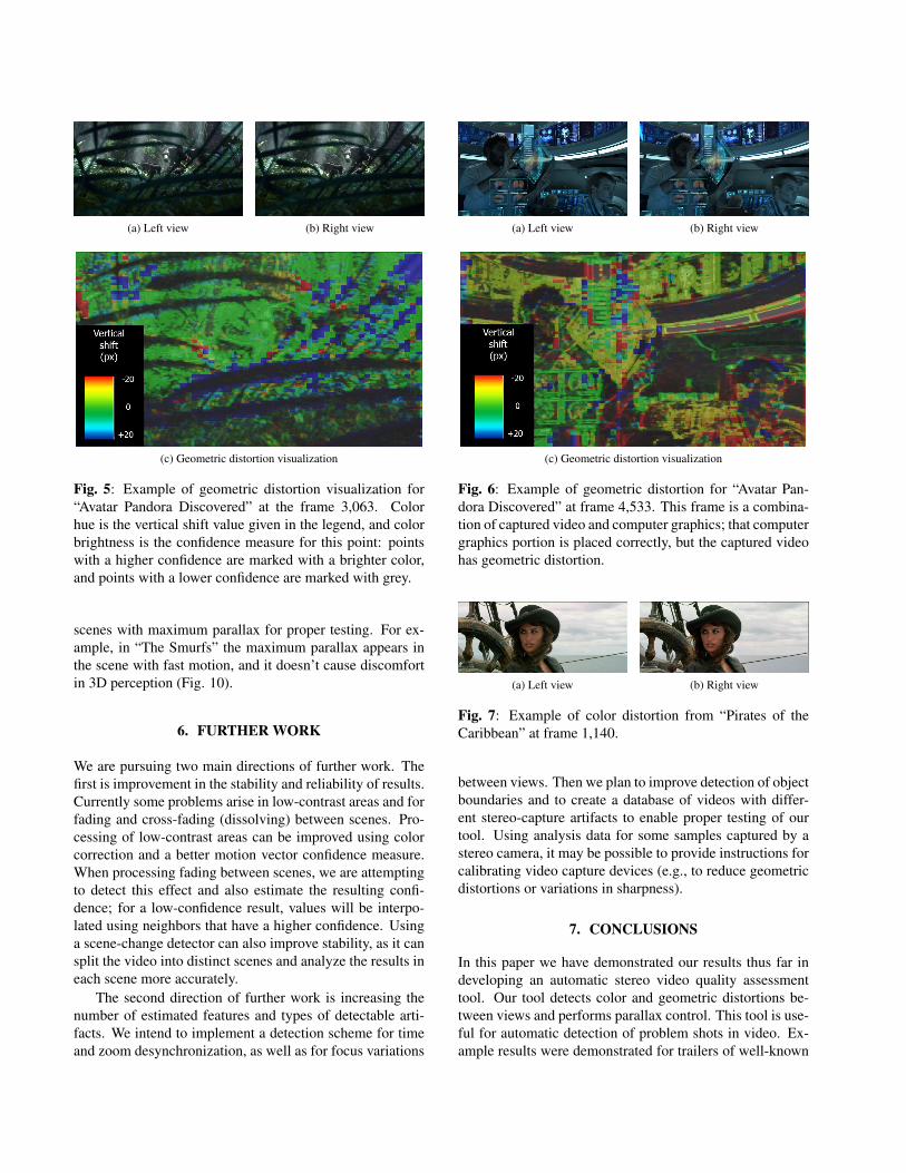
Fig. 5: Example of geometric distortion visualization for“Avatar Pandora Discovered” at the frame 3,063. Colorhue is the vertical shift value given in the legend, and colorbrightness is the confidence measure for this point: pointswith a higher confidence are marked with a brighter color,and points with a lower confidence are marked with grey.
scenes with maximum parallax for proper testing. For ex-ample, in “The Smurfs” the maximum parallax appears inthe scene with fast motion, and it doesn’t cause discomfortin 3D perception (Fig. 10).
6. FURTHER WORK
We are pursuing two main directions of further work. Thefirst is improvement in the stability and reliability of results.Currently some problems arise in low-contrast areas and forfading and cross-fading (dissolving) between scenes. Pro-cessing of low-contrast areas can be improved using colorcorrection and a better motion vector confidence measure.When processing fading between scenes, we are attemptingto detect this effect and also estimate the resulting confi-dence; for a low-confidence result, values will be interpo-lated using neighbors that have a higher confidence. Usinga scene-change detector can also improve stability, as it cansplit the video into distinct scenes and analyze the results ineach scene more accurately.
The second direction of further work is increasing thenumber of estimated features and types of detectable arti-facts. We intend to implement a detection scheme for timeand zoom desynchronization, as well as for focus variations
(a) Left view (b) Right view
(c) Geometric distortion visualization
Fig. 6: Example of geometric distortion for “Avatar Pan-dora Discovered” at frame 4,533. This frame is a combina-tion of captured video and computer graphics; that computergraphics portion is placed correctly, but the captured videohas geometric distortion.
(a) Left view (b) Right view
Fig. 7: Example of color distortion from “Pirates of theCaribbean” at frame 1,140.
between views. Then we plan to improve detection of objectboundaries and to create a database of videos with differ-ent stereo-capture artifacts to enable proper testing of ourtool. Using analysis data for some samples captured by astereo camera, it may be possible to provide instructions forcalibrating video capture devices (e.g., to reduce geometricdistortions or variations in sharpness).
7. CONCLUSIONS
In this paper we have demonstrated our results thus far indeveloping an automatic stereo video quality assessmenttool. Our tool detects color and geometric distortions be-tween views and performs parallax control. This tool is use-ful for automatic detection of problem shots in video. Ex-ample results were demonstrated for trailers of well-known

(a) Left view (b) Right view
Fig. 8: Example of color distortion from “Resident Evil 4:Afterlife” at frame 2,790.
(a) Left view (b) Right view
(c) Disparity map visualization (d) Anaglyph stereo
Fig. 10: Frame 1,962 from “The Smurfs” trailer with exam-ple of maximum parallax visualization. This scene has fastmotion, so a large parallax doesn’t cause discomfort in 3Dperception.
movies, and we showed that these trailers contained someartifacts. Our tool is in an early development stage, but inthe future, we plan to increase the number of solutions torecognizable problems and improve the stability of results.
8. ACKNOWLEDGEMENTS
This work is partially supported by the Intel/Cisco Video-Aware Wireless Network (VAWN) Program and by grant10-01-00697a from the Russian Foundation of Basic Re-search.
9. REFERENCES
[1] Kenji Yamamoto and Ryutaro Oi, “Color correctionfor multi-view video using energy minimization ofview networks,” International Journal of Automationand Computing, vol. 5, no. 3, pp. 234–245, 2008.
[2] J.J. Yu, H.D. Kim, H.W. Jang, and S.W. Nam,“A hybrid color matching between stereo image se-
quences,” Proceedings of 3DTV-Conference 2011, pp.1–4, 2011.
[3] Guo-Yu Lin, Xu Chen, and Wei-Gong Zhang, “Arobust epipolar rectification method of stereo pairs,”Measuring Technology and Mechatronics Automation,International Conference on, vol. 1, pp. 322–326,2010.
[4] J. Zhou and B.X. Li, “Image rectification for stereo-scopic visualization without 3d glasses,” in Image andVideo Retrieval. 2006, pp. 495–498, Springer Berlin /Heidelberg.
[5] Colin Doutre, Mahsa T. Pourazad, Alexis M. Tourapis,Panos Nasiopoulos, and Rabab K. Ward, “Correctingunsynchronized zoom in 3d video,” Proceedings ofIEEE International Symposium on Circuits and Sys-tems, pp. 3244–3247, 2010.
[6] Luhong Liang, Jianhua Chen, Siwei Ma, Debin Zhao,and Wen Gao, “A no-reference perceptual blur metricusing histogram of gradient profile sharpness,” Pro-ceedings of the 16th IEEE International Conferenceon Image Orocessing, pp. 4309–4312, 2009.
[7] Yaron Caspi and Michal Irani, “Spatio-temporal align-ment of sequences,” IEEE Transactions on PatternAnalysis and Machine Intelligence, vol. 24, pp. 1409–1424, 2002.
[8] V. Guitteny, R. Benosman, and C. Charbuillet, “Syn-chronizing video sequences from temporal epipolarlines analysis,” in Advanced Concepts for IntelligentVision Systems, October 2008.
[9] Jingyu Yan and Marc Pollefeys, “Video synchroniza-tion via space-time interest point distribution,” Pro-ceedings of Advanced Concepts for Intelligent VisionSystems, 2004.
[10] Karen Simonyan, Sergey Grishin, Dmitriy Vatolin,and Dmitriy Popov, “Fast video super-resolution viaclassification,” pp. 349–352, 2008.
[11] Karen Simonyan, Sergey Grishin, Dmitriy Vatolin,and Dmitriy Popov, “Confidence measure for block-based motion vector field,” Graphicon, pp. 110–113,2008.

Fig. 9: Graph demonstrating different parallax control strategies for different movie trailers. For the movies “Transformers3” and “Bitwa Warszawska,” the depth was consistent throughout the entire video, but in “Pirates of the Caribbean” and “TheSmurfs,” scenes have different 3D effects.