System engineering the Space Infrared Interferometric Telescope (SPIRIT) · · 2013-04-10System...
12
System engineering the Space Infrared Interferometric Telescope (SPIRIT) T. Tupper Hyde, David T. Leisawitz, David A. Di Pietro, and Stephen A. Rinehart NASA Goddard Spaceflight Center (GSFC), 8800 Greenbelt Rd., Greenbelt, MD 20771 ABSTRACT The Space Infrared Interferometric Telescope (SPIRIT) was designed to accomplish three scientific objectives: (1) learn how planetary systems form from protostellar disks and how they acquire their inhomogeneous chemical composition; (2) characterize the family of extrasolar planetary systems by imaging the structure in debris disks to understand how and where planets of different types form; and (3) learn how high-redshift galaxies formed and merged to form the present-day population of galaxies. SPIRIT will accomplish these objectives through infrared observations with a two aperture interferometric instrument. This paper gives an overview of SPIRIT design and operation, and how the three design cycle concept study was completed. The error budget for several key performance values allocates tolerances to all contributing factors, and a performance model of the spacecraft plus instrument system demonstrates meeting those allocations with margin. Keywords: SPIRIT, InfraredAR, Interferometry, Telescope, System Engineering, Error Budget 1 INTRODUCTION The Space Infrared Interferometric Telescope (SPIRIT) will provide integral field spectroscopy throughout the wavelength range 25 - 400 ym with sub-arcsecond angular resolution and hIAh = 3000 spectral resolution in a 1 arcminute instantaneous field of view. Many of the astronomical targets of interest will be resolved for the first time at far-IR wavelengths. SPIRIT's spatially resolved spectra will break model degeneracy and enable a new physical understanding of forming stars and planetary systems, mature planetary systems, and galaxies. A single scientific instrument gives SPIRIT its powerful combination of spatial and spectroscopic measurement capabilities. SPIRIT is a Michelson stellar interferometer with a scanning optical delay line for Fourier transform spectroscopy and compensation of external optical path length differences. Following beam combination in the pupil plane, detector arrays multiplex the area coverage, expanding the field of view from the diffraction spot size of the individual light collecting telescopes to the desired arcminute scale. SPIRIT's two telescopes can be moved to sample many interferometric baselines, and therefore spatial structure on all of the angular scales necessary to produce high- quality far-IR images. The image resolution, 0.3 (h1100 ym) arcsec, is determined by the maximum baseline length, 36 m. To attain superlative sensitivity, limited by astrophysical background photon noise, the SPIRIT optics are cooled to 4 K and sufficiently sensitive detectors will be used. The results of a pre-Formulation Phase study of the SPIRIT mission concept are given in a series of papers, of which this paper is one. The scientific objectives, measurement requirements, and an overview of the design concept are described by Leisawitz et al. (2007).[11 Wilson et al. (2007) 12] describes the optics and stray light trades. Budinoff et al. (2007) 13] describes the SPIRIT mechanical design and mechanisms and explains how the mechanical design will meet instrument stability, thermal and packaging requirements. DiPirro et al. (2007) [41 present the thermal design concept, thermal modeling results, and the cooling ower requirements, and they explain how cryocoolers will be used to meet these 751 requirements. Benford et al. (2007) describe detector requirements, including NEP, pixel count and readout speed, and present the rationale for using small arrays of TES bolometers. Rinehart et al. (2007) 16] update the status of our development of the wide-field imaging interferometry technique applicable to SPIRIT, and Martino et al. (2007) ['I describe a model of the Wide-field Imaging Interferometry Testbed, a model which can be adapted to simulate interferometric data from SPIRIT. This paper covers the system engineering of SPIRIT: a walk-through of SPIRIT's design and operation, a re-cap of the three design cycle concept study, and an error budget and performance estimates for key interferometric performance metrics. *[email protected]; phone 301 286 5386; Applied Engineering and Technology Directorate, NASA GSFC. https://ntrs.nasa.gov/search.jsp?R=20070034990 2018-05-28T08:06:45+00:00Z
Transcript of System engineering the Space Infrared Interferometric Telescope (SPIRIT) · · 2013-04-10System...
System engineering the Space Infrared Interferometric Telescope (SPIRIT)
T. Tupper Hyde, David T. Leisawitz, David A. Di Pietro, and Stephen A. Rinehart NASA Goddard Spaceflight Center (GSFC), 8800 Greenbelt Rd., Greenbelt, MD 20771
ABSTRACT
The Space Infrared Interferometric Telescope (SPIRIT) was designed to accomplish three scientific objectives: (1) learn how planetary systems form from protostellar disks and how they acquire their inhomogeneous chemical composition; (2) characterize the family of extrasolar planetary systems by imaging the structure in debris disks to understand how and where planets of different types form; and (3) learn how high-redshift galaxies formed and merged to form the present-day population of galaxies. SPIRIT will accomplish these objectives through infrared observations with a two aperture interferometric instrument. This paper gives an overview of SPIRIT design and operation, and how the three design cycle concept study was completed. The error budget for several key performance values allocates tolerances to all contributing factors, and a performance model of the spacecraft plus instrument system demonstrates meeting those allocations with margin.
Keywords: SPIRIT, InfraredAR, Interferometry, Telescope, System Engineering, Error Budget
1 INTRODUCTION The Space Infrared Interferometric Telescope (SPIRIT) will provide integral field spectroscopy throughout the wavelength range 25 - 400 ym with sub-arcsecond angular resolution and hIAh = 3000 spectral resolution in a 1 arcminute instantaneous field of view. Many of the astronomical targets of interest will be resolved for the first time at far-IR wavelengths. SPIRIT's spatially resolved spectra will break model degeneracy and enable a new physical understanding of forming stars and planetary systems, mature planetary systems, and galaxies.
A single scientific instrument gives SPIRIT its powerful combination of spatial and spectroscopic measurement capabilities. SPIRIT is a Michelson stellar interferometer with a scanning optical delay line for Fourier transform spectroscopy and compensation of external optical path length differences. Following beam combination in the pupil plane, detector arrays multiplex the area coverage, expanding the field of view from the diffraction spot size of the individual light collecting telescopes to the desired arcminute scale. SPIRIT's two telescopes can be moved to sample many interferometric baselines, and therefore spatial structure on all of the angular scales necessary to produce high- quality far-IR images. The image resolution, 0.3 (h1100 ym) arcsec, is determined by the maximum baseline length, 36 m. To attain superlative sensitivity, limited by astrophysical background photon noise, the SPIRIT optics are cooled to 4 K and sufficiently sensitive detectors will be used.
The results of a pre-Formulation Phase study of the SPIRIT mission concept are given in a series of papers, of which this paper is one. The scientific objectives, measurement requirements, and an overview of the design concept are described by Leisawitz et al. (2007).[11 Wilson et al. (2007) 12] describes the optics and stray light trades. Budinoff et al. (2007) 13] describes the SPIRIT mechanical design and mechanisms and explains how the mechanical design will meet instrument stability, thermal and packaging requirements. DiPirro et al. (2007) [41 present the thermal design concept, thermal modeling results, and the cooling ower requirements, and they explain how cryocoolers will be used to meet these
751 requirements. Benford et al. (2007) describe detector requirements, including NEP, pixel count and readout speed, and present the rationale for using small arrays of TES bolometers. Rinehart et al. (2007) 16] update the status of our development of the wide-field imaging interferometry technique applicable to SPIRIT, and Martino et al. (2007) ['I describe a model of the Wide-field Imaging Interferometry Testbed, a model which can be adapted to simulate interferometric data from SPIRIT. This paper covers the system engineering of SPIRIT: a walk-through of SPIRIT's design and operation, a re-cap of the three design cycle concept study, and an error budget and performance estimates for key interferometric performance metrics.
*[email protected]; phone 301 286 5386; Applied Engineering and Technology Directorate, NASA GSFC.
https://ntrs.nasa.gov/search.jsp?R=20070034990 2018-05-28T08:06:45+00:00Z
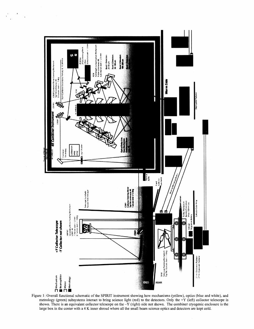
Figure 1 : Overall functional schematic of the SPIRIT instrument showing how mechanisms (yellow), optics (blue and white), and metrology (green) subsystems interact to bring science light (red) to the detectors. Only the +Y (left) collector telescope is shown. There is an equivalent collector telescope on the -Y (right) side not shown. The combiner cryogenic enclosure is the large box in the center with a 4 K inner shroud where all the small beam science optics and detectors are kept cold.
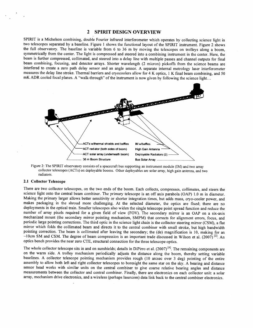
2 SPIRIT DESIGN OVERVIEW SPIRIT is a Michelson combining, double Fourier infrared interferometer which operates by collecting science light in two telescopes separated by a baseline. Figure 1 shows the functional layout of the SPIRIT instrument. Figure 2 shows the full observatory. The baseline is variable from 6 to 36 m by moving the telescopes on trolleys along a boom, symmetrically from the center. The light is compressed and steered into a combining instrument in the center. Here, the beam is further compressed, collimated, and steered into a delay line with multiple passes and channel outputs for final beam combining, focusing, and detector arrays. Shorter wavelength (2 micron) pickoffs from the science beams are interfered to create a zero path delay sensor and an angle sensor. A separate internal metrology laser interferometer measures the delay line stroke. Thermal barriers and cryocoolers allow for 4 K optics, 1 K final beam combining, and 50 mK ADR cooled focal planes. A "walk-through" of the instrument is now given by following the science light.. .
ACTS wlthermal shields and baffles IM wlbaffles
ACT radiator (both sides of boom) High Gain Antenna
ACT solar array (underneath boom) Deployable Radiators (2) - 36 m Boom Structure Bus Solar Array - \
Figure 2: The SPIRIT observatory consists of a spacecraft bus supporting an instrument module (IM) and two array collector telescopes (ACTS) on deployable booms. Other deployables are solar array, high gain antenna, and two radiators.
2.1 Collector Telescope
There are two collector telescopes, on the two ends of the boom. Each collects, compresses, collimates, and steers the science light onto the central beam combiner. The primary telescope is an off axis parabola (OAP) 1.0 m in diameter. Making the primary larger allows better sensitivity or shorter integration times, but adds mass, cryo-cooler power, and makes packaging in the shroud more challenging. At the selected diameter, the optics are fixed; there are no deployments in the optical train. Smaller telescopes also widen the single telescope point spread function and reduce the number of array pixels required for a given field of view (FOV). The secondary mirror is an OAP on a six-axis mechanized mount (the secondary mirror pointing mechanism, SMPM) that corrects for alignment errors, focus, and periodic large pointing corrections. The third optic in the science light chain is the collector steering mirror (CSM), a flat mirror which folds the collimated beam and directs it to the central combiner with small stroke, but high bandwidth pointing correction. The beam is collimated after leaving the secondary; the (de) magnification is 10, making for an -10cm SM and CSM. The degree of beam compression is an important trade discussed in Wilson et al. (2007) 12]. An optics bench provides the near zero CTE, structural connection for the three telescope optics.
The whole collector telescope sits in and on sunshields; details in DiPirro et al. (2007) 14]. The remaining components are on the warm side. A trolley mechanism periodically adjusts the distance along the boom, thereby setting variable baselines. A collector telescope pointing mechanism provides rough (10 arcsec over 3 deg) pointing of the entire assembly to allow both left and right collector telescopes to boresight the same star on the sky. A bearing and distance sensor head works with similar units on the central combiner to give coarse relative bearing angles and distance measurements between the collector and central combiner. Finally, there are electronics on each collector unit: a solar array, mechanism drive electronics, and a wireless (perhaps lasercom) data link back to the central combiner electronics.
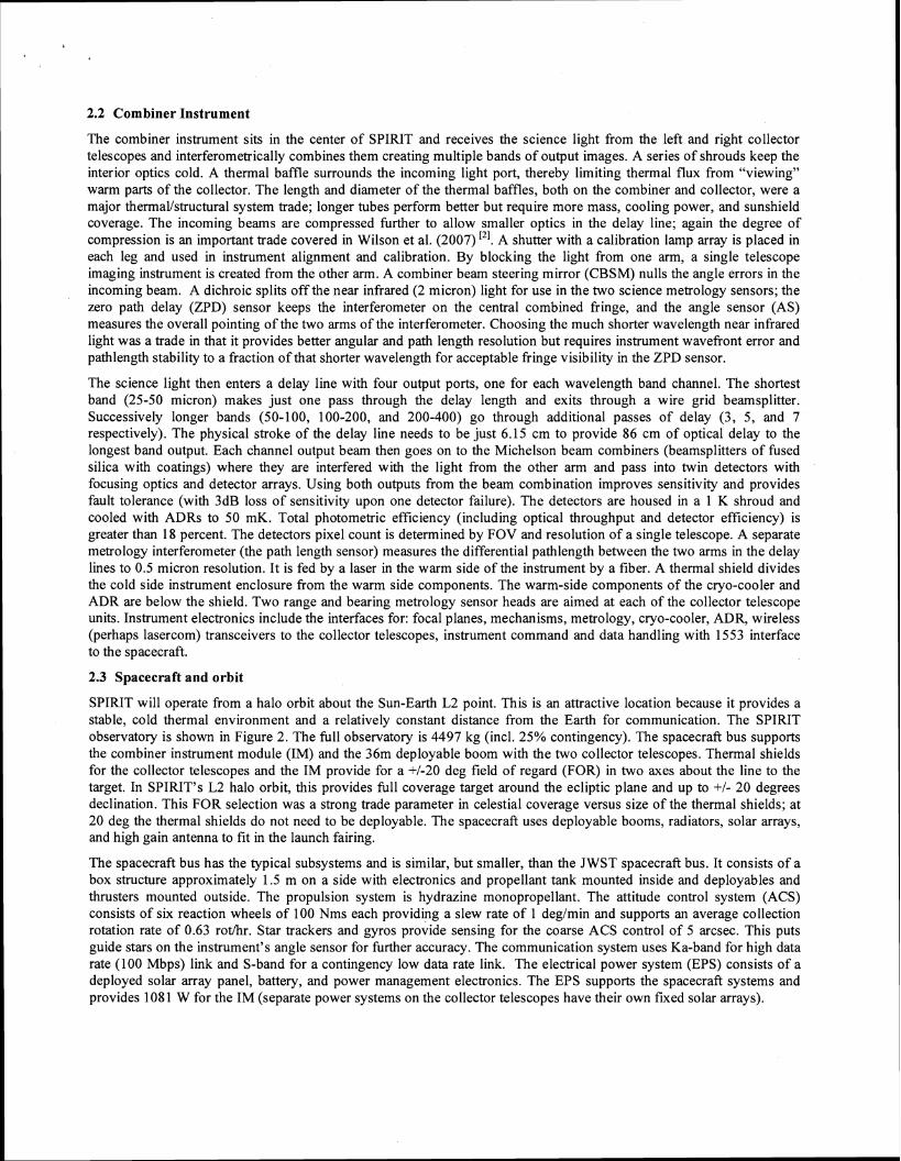
2.2 Combiner Instrument
The combiner instrument sits in the center of SPIRIT and receives the science light from the left and right collector telescopes and interferometrically combines them creating multiple bands of output images. A series of shrouds keep the interior optics cold. A thermal baffle surrounds the incoming light port, thereby limiting thermal flux from "viewing" warm parts of the collector. The length and diameter of the thermal baffles, both on the combiner and collector, were a major thermallstructural system trade; longer tubes perform better but require more mass, cooling power, and sunshield coverage. The incoming beams are compressed further to allow smaller optics in the delay line; again the degree of compression is an important trade covered in Wilson et al. (2007) ['I. A shutter with a calibration lamp array is placed in each leg and used in instrument alignment and calibration. By blocking the light from one arm, a single telescope imaging instrument is created from the other arm. A combiner beam steering mirror (CBSM) nulls the angle errors in the incoming beam. A dichroic splits off the near infrared (2 micron) light for use in the two science metrology sensors; the zero path delay (ZPD) sensor keeps the interferometer on the central combined fringe, and the angle sensor (AS) measures the overall pointing of the two arms of the interferometer. Choosing the much shorter wavelength near infrared light was a trade in that it provides better angular and path length resolution but requires instrument wavefront error and pathlength stability to a fraction of that shorter wavelength for acceptable fringe visibility in the ZPD sensor.
The science light then enters a delay line with four output ports, one for each wavelength band channel. The shortest band (25-50 micron) makes just one pass through the delay length and exits through a wire grid beamsplitter. Successively longer bands (50-100, 100-200, and 200-400) go through additional passes of delay (3, 5, and 7 respectively). The physical stroke of the delay line needs to be just 6.15 cm to provide 86 cm of optical delay to the longest band output. Each channel output beam then goes on to the Michelson beam combiners (beamsplitters of fused silica with coatings) where they are interfered with the light from the other arm and pass into twin detectors with focusing optics and detector arrays. Using both outputs from the beam combination improves sensitivity and provides fault tolerance (with 3dB loss of sensitivity upon one detector failure). The detectors are housed in a 1 K shroud and cooled with ADRs to 50 mK. Total photometric efficiency (including optical throughput and detector efficiency) is greater than 18 percent. The detectors pixel count is determined by FOV and resolution of a single telescope. A separate metrology interferometer (the path length sensor) measures the differential pathlength between the two arms in the delay lines to 0.5 micron resolution. It is fed by a laser in the warm side of the instrument by a fiber. A thermal shield divides the cold side instrument enclosure from the warm side components. The warm-side components of the cryo-cooler and ADR are below the shield. Two range and bearing metrology sensor heads are aimed at each of the collector telescope units. Instrument electronics include the interfaces for: focal planes, mechanisms, metrology, cryo-cooler, ADR, wireless (perhaps lasercom) transceivers to the collector telescopes, instrument command and data handling with 1553 interface to the spacecraft.
2.3 Spacecraft and orbit
SPIRIT will operate from a halo orbit about the Sun-Earth L2 point. This is an attractive location because it provides a stable, cold thermal environment and a relatively constant distance from the Earth for communication. The SPIRIT observatory is shown in Figure 2. The full observatory is 4497 kg (incl. 25% contingency). The spacecraft bus supports the combiner instrument module (IM) and the 36m deployable boom with the two collector telescopes. Thermal shields for the collector telescopes and the IM provide for a +I-20 deg field of regard (FOR) in two axes about the line to the target. In SPIRIT'S L2 halo orbit, this provides full coverage target around the ecliptic plane and up to +I- 20 degrees declination. This FOR selection was a strong trade parameter in celestial coverage versus size of the thermal shields; at 20 deg the thermal shields do not need to be deployable. The spacecraft uses deployable booms, radiators, solar arrays, and high gain antenna to fit in the launch fairing.
The spacecraft bus has the typical subsystems and is similar, but smaller, than the JWST spacecraft bus. It consists of a box structure approximately 1.5 m on a side with electronics and propellant tank mounted inside and deployables and thrusters mounted outside. The propulsion system is hydrazine monopropellant. The attitude control system (ACS) consists of six reaction wheels of 100 Nms each providing a slew rate of 1 degimin and supports an average collection rotation rate of 0.63 r o a r . Star trackers and gyros provide sensing for the coarse ACS control of 5 arcsec. This puts guide stars on the instrument's angle sensor for further accuracy. The communication system uses Ka-band for high data rate (100 Mbps) link and S-band for a contingency low data rate link. The electrical power system (EPS) consists of a deployed solar array panel, battery, and power management electronics. The EPS supports the spacecraft systems and provides 1081 W for the IM (separate power systems on the collector telescopes have their own fixed solar arrays).
2.4 Operation
SPIRIT will be launched on a medium EELV with a 5 m fairing directly to its L2 transfer orbit. The spacecraft performs small correction and halo orbit insertion burns. SPIRIT will operate for 3 years with a 5-year goal (propellant for 5 years). Orbit station keeping maneuvers are performed infrequently (every few months). The primary driver for operations .is science efficiency, that is, percent of total time spent integrating on detectors. Slewing to new targets, trolley positioning, alignments, calibration, and data downlink time must be minimized. Data downlinks occur every other day for two hours at 100 Mbps to DSN allowing 247 Gbitslday of science and housekeeping data (includes encoding overhead, margin and assumes 2:l compression on science data).
A typical observation begins by slewing to the new target, typically 10 degrees away in less than 2 hours. The spacecraft spins slowly axis towards target. Calibrations and alignments take a few minutes. The target is observed for % a revolution, and then the trolley moves to a new position (while continuing to spin). Trolley spacing is dependent on desired U-V plane coverage but typically consists of 31 positions with baselines from 6 to 36 m. Downlinks interrupt science observations. During integration, the delay line is continuously stroked over the full range during the time the collecting telescopes have moved one half of a diameter tangentially due to spacecraft rotation. Images are read from the 8 focal planes (2 each of the 4 channels) which creates an on- board data set with baseline, rotation angle, and delay line stroke per image read. Frame read rates depend on stoke rate and channel and are is 573 Hz on the short wavelength channel typically. This results in a total uncompressed raw science data rate of 5.4 Mbps. This data is post-processed on the ground to create a double Fourier data set with high spatial and spectral resolution. Total integration time depends on the desired sensitivity but typically is 24 hours of detector integration in 28.2 hour (29 hour with margin) total observation for 85 percent science efficiency and a 0.85 targetslday mission planning number.
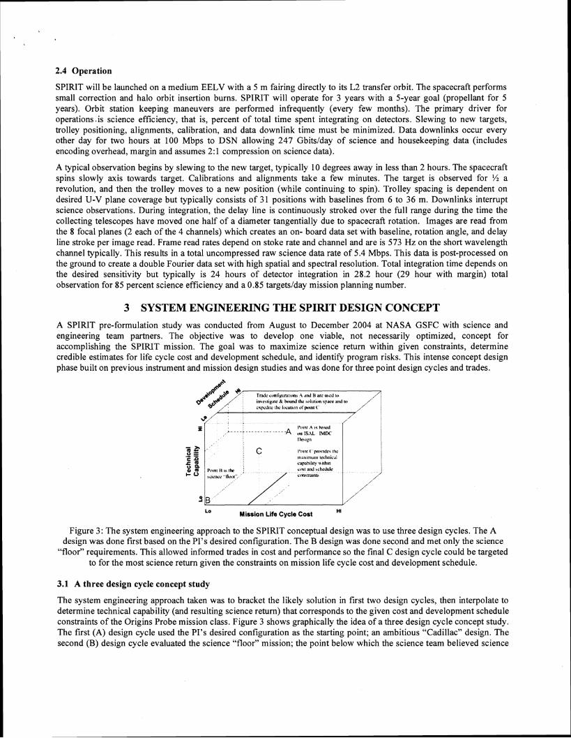
3 SYSTEM ENGINEERING THE SPIRIT DESIGN CONCEPT A SPIRIT pre-formulation study was conducted from August to December 2004 at NASA GSFC with science and engineering team partners. The objective was to develop one viable, not necessarily optimized, concept for accomplishing the SPIRIT mission. The goal was to maximize science return within given constraints, determine credible estimates for life cycle cost and development schedule, and identify program risks. This intense concept design phase built on previous instrument and mission design studies and was done for three point design cycles and trades.
LO Mission Life Cycle Cost
Figure 3 : The system engineering approach to the SPIRIT conceptual design was to use three design cycles. The A design was done first based on the PI's desired configuration. The B design was done second and met only the science
"floor" requirements. This allowed informed trades in cost and performance so the final C design cycle could be targeted to for the most science return given the constraints on mission life cycle cost and development schedule.
3.1 A three design cycle concept study
The system engineering approach taken was to bracket the likely solution in first two design cycles, then interpolate to determine technical capability (and resulting science return) that corresponds to the given cost and development schedule constraints of the Origins Probe mission class. Figure 3 shows graphically the idea of a three design cycle concept study. The first (A) design cycle used the PI's desired configuration as the starting point; an ambitious "Cadillac" design. The second (B) design cycle evaluated the science "floor" mission; the point below which the science team believed science
return would not justify the investment; an austere design. Trades were then introduced by each subsystem design lead and integrated by the instrument and mission system engineers to create a trade sensitivity and breakpoint matrix with overall system capabilities tied to costs and packaging feasibility. While the engineering team was conducting trades in preparation for targeting the final (C) design cycle parameters, the science team was completing a design reference mission (DRM) with 15 "use cases" defined by individual science team champions. Established SPIRIT primary and secondary science goals were used to weight the science utility the use cases. Each use case then derived it's science requirements: field o f view, field o f regard, number o f fields, wavelength range, spatial resolution, spectral resolution, and sensitivity. Evaluation of the D R M information allowed for informed targeting of the C design cycle parameter to get the most completion of the D R M with a mission concept that would meet constraints. Engineering and science teams then met with the PI to define the targeted critical parameters for the final (C) design cycle. The results of the C design were those presented in the previous section. Table two lists critical parameters for the A, B, and C design cycles for side-by-side comparison.
3.2 Lessons learned
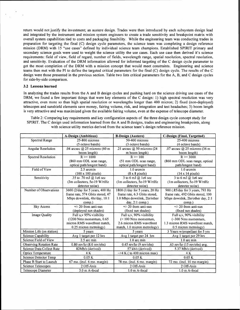
In analyzing the trades results from the A and B design cycles and pushing hard on the science driving use cases o f the DRM, w e found a few important things that were key elements o f the C design: 1) high spectral resolution was very attractive, even more so than high spatial resolution or wavelengths longer than 400 micron; 2) fixed (non-deployed) telescopes and sunshield elements save money, fairing volume, risk, and integration and test headaches; 3) boom length is very attractive and was maximized given the available fairing volume, even at the expense of telescope diameter.
Table 2: Comparing key requirements and key configuration aspects o f the three design cycle concept study for SPIRIT. The C design used information learned from the A and B designs, trades and engineering breakpoints, along
with science utility metrics derived from the science team's design reference mission.
Spectral Range
Angular Resolution
A-Design (Ambitious) 25-800 microns (5 octave bands)
.04 arcsec @ 25 microns (60 m
B-Design (Austere) 50-400 microns (3 octave bands)
.21 arcsec @ 50 microns (24
C-Design (Final, Targetted) 25-400 microns (4 octave bands)
.07 arcsec @ 25 microns (36 m
Spectral Resolution
Field of View
Sensitivity
Number of Observations
Sky Access
Image Quality
Mission Life (on station) Science Capability
R >= 1000 (860 mm ODL scan range, optical pathllongest band)
2.5 arcmin (100 x 100 pixels)
.35 to .70 mJ @ le6 sec (3m collectors, 5e-19 WIrtHz
detector noise) 3600 (2lday for 5 years, 400 Hz frame rate, 574 Gbits stored, 47 Mbps downlink, 4hr/day, 10: 1
comp.) +I- 20 from anti-sun
(deployed sun shades) Full u,v 95% visibility
(1200 Nms momentum, 0.65 micron RMS wavefront match,
0.25 micron metrology) 5 years
Science Field of View Observing Rotation Rate Science Data Collect Rate Optics Temperature Science Detector Temp
R >= 100 (5 1 mm ODL scan range, optical pathllongest band)
1.0 arcmin (8 x 8 pixels)
3 to 6 mJ @ le6 sec ( lm collectors, 5e-19 WIrtHz
detector noise) 1800 (llday for 5 years, 20 Hz frame rate, 6.3 Gbits stored,
1.0 Mbps downlink, 2hrlother day, 2: 1 comp.)
+I- 20 from anti-sun (fixed sun shades)
Full u,v, 90% visibility (< 100 Nms momentum,
2.6 micron RMS wavefront match, 1.0 micron metrology)
5 years
R >= 3000 (860 mm ODL scan range, optical
pathllongest band) 1.0 arcmin
(14 x 14 pixels) 3 to 6 mJ @ le6 sec
( l m collectors, 5e-19 WlrtHz detector noise)
900 (.85lday for 3 years, 793 Hz frame rate, 492 Gbits stored, 100
Mbps downlnk, 2hrlother day, 2:l comp.)
+I- 20 from anti-sun (fixed sun shades)
Full u,v, 90% visibility (-300 Nms momentum,
1.3 micron RMS wavefront match, 0.5 micron metrology)
3 Years wlpropellant for 5 yrs
Phase B Start to Launch Science Telescopes 2 Off-Axis 2 Off-Axis 2 Off-Axis Telescope Diameter 3.0 m A-focal 1.0 m A-focal 1.0 m A-focal
2.5 arc min 0.80 revihr (8.0 revlobs)
82Mbls (derived) 4 K
0.05 K
1.0 arc min 0.45 revihr (9 revlobs)
57 kbls (derived) ->4 K ( to 400 micron max)
0.05 K
1.0 arc min .63 revihr (1 5 revlobs) avg.
5.37 Mbls (derived) 4 K
0.05 K
4 INTERFEROMETRIC ERROR BUDGET AND PERFORMANCE ESTIMATES
Ground Contacts Instrument Cold Mass Observ. Mass, Wet (kg) Instr Power, EOL (W) Fairing Diameter (m)
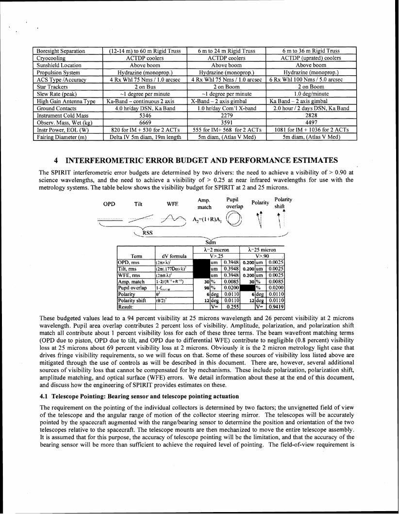
The SPIRIT interferometric error budgets are determined by two drivers: the need to achieve a visibility of > 0.90 at science wavelengths, and the need to achieve a visibility of > 0.25 at near infrared wavelengths for use with the metrology systems. The table below shows the visibility budget for SPIRIT at 2 and 25 microns.
These budgeted values lead to a 94 percent visibility at 25 microns wavelength and 26 percent visibility at 2 microns wavelength. Pupil area overlap contributes 2 percent loss of visibility. Amplitude, polarization, and polarization shift match all contribute about 1 percent visibility loss for each of these three terms. The beam wavefront matching terms (OPD due to piston, OPD due to tilt, and OPD due to differential WFE) contribute to negligible (0.8 percent) visibility loss at 25 microns about 69 percent visibility loss at 2 microns. Obviously it is the 2 micron metrology light case that drives fringe visibility requirements, so we will focus on that. Some of these sources of visibility loss listed above are mitigated through the use of controls as will be described in this document. There are, however, several additional sources of visibility loss that cannot be compensated for by mechanisms. These include polarization, polarization shift, amplitude matching, and optical surface (WFE) errors. We detail information about these at the end of this document, and discuss how the engineering of SPIRIT provides estimates on these.
4.0 hrlday DSN, Ka Band 5346 6669
820 for IM + 530 for 2 ACTS Delta 1V 5m dim, 19m length
4.1 Telescope Pointing: Bearing sensor and telescope pointing actuation
The requirement on the pointing of the individual collectors is determined by two factors; the unvignetted field of view of the telescope and the angular range of motion of the collector steering mirror. The telescopes will be accurately pointed by the spacecraft augmented with the rangehearing sensor to determine the position and orientation of the two telescopes relative to the spacecraft. The telescope mounts are then mechanized to move the entire telescope assembly. It is assumed that for this purpose, the accuracy of telescope pointing will be the limitation, and that the accuracy of the bearing sensor will be more than sufficient to achieve the required level of pointing. The field-of-view requirement is
1.0 hrlday Com'l X-band 2279 3591
555 for IM+ 568 for 2 ACTS 5m dim, (Atlas V Med)
2.0 hour I 2 days DSN, Ka Band 2828 4497
1081 for IM + 1036 for 2 ACTS 5m dim, (Atlas V Med)
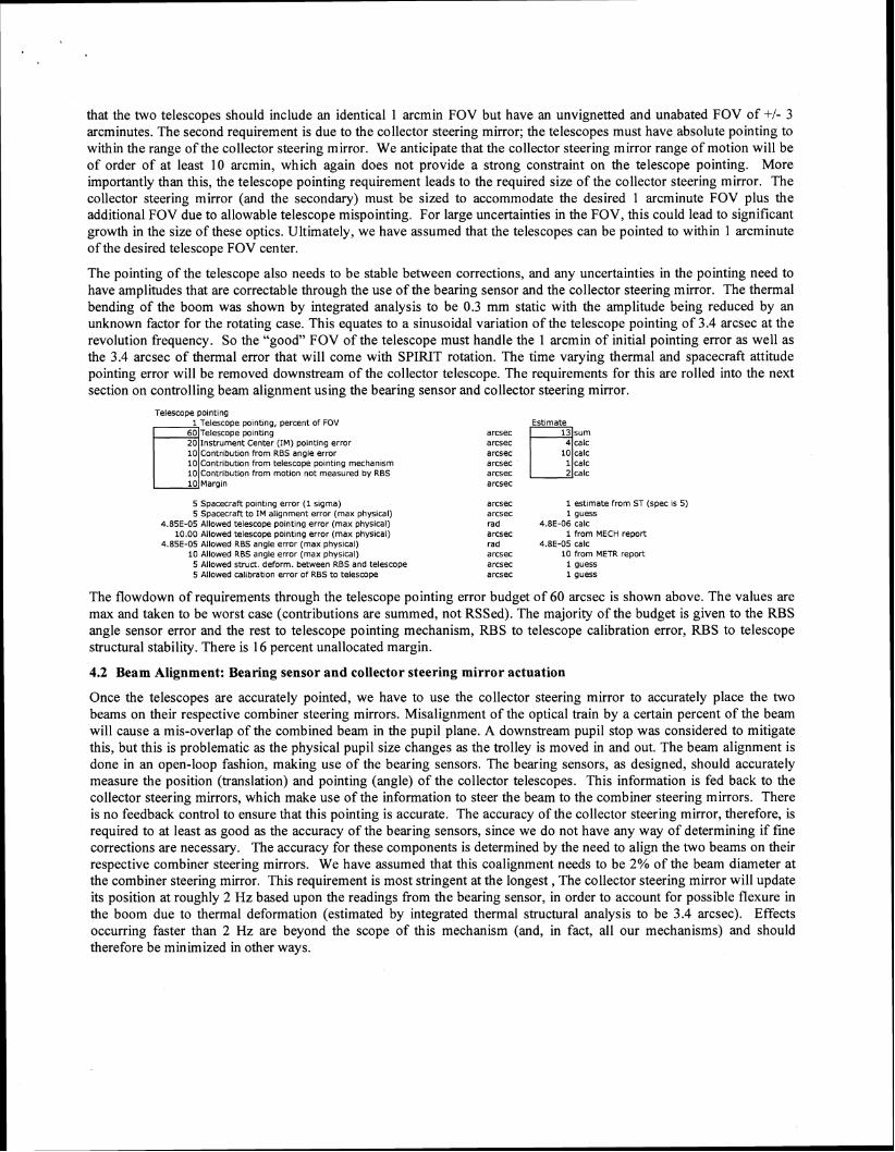
that the two telescopes should include an identical 1 arcmin FOV but have an unvignetted and unabated FOV of +I- 3 arcminutes. The second requirement is due to the collector steering mirror; the telescopes must have absolute pointing to within the range of the collector steering mirror. We anticipate that the collector steering mirror range of motion will be of order of at least 10 arcmin, which again does not provide a strong constraint on the telescope pointing. More importantly than this, the telescope pointing requirement leads to the required size of the collector steering mirror. The collector steering mirror (and the secondary) must be sized to accommodate the desired 1 arcminute FOV plus the additional FOV due to allowable telescope mispointing. For large uncertainties in the FOV, this could lead to significant growth in the size of these optics. Ultimately, we have assumed that the telescopes can be pointed to within 1 arcminute of the desired telescope FOV center.
The pointing of the telescope also needs to be stable between corrections, and any uncertainties in the pointing need to have amplitudes that are correctable through the use of the bearing sensor and the collector steering mirror. The thermal bending of the boom was shown by integrated analysis to be 0.3 mm static with the amplitude being reduced by an unknown factor for the rotating case. This equates to a sinusoidal variation of the telescope pointing of 3.4 arcsec at the revolution frequency. So the "good" FOV of the telescope must handle the 1 arcmin of initial pointing error as well as the 3.4 arcsec of thermal error that will come with SPIRIT rotation. The time varying thermal and spacecraft attitude pointing error will be removed downstream of the collector telescope. The requirements for this are rolled into the next section on controlling beam alignment using the bearing sensor and collector steering mirror.
Telescope polntlng 1 Telescope polntlng, percent of FOV
60 Telescope polntlng -Instrument Center (IM) oolntlna error ~,
from RBS angle error from telescope polntlng mechan~sm from motlon not measured by RBS
5 Spacecraft polntlng error ( 1 slgma) 5 Spacecraft to IM alignment error (max phys~cal)
4 85E-05 Allowed telescope polntlng error (rnax physlcal) 10.00 Allowed telescope polntlng error (max physlcal)
4 85E-05 Allowed RBS angle error (max physlcal) 10 Allowed RBS angle error (max physlcal) 5 Allowed struct deform. between RBS and telescope 5 Allowed callbratlon error of RBS to telescope
arcsec arcsec arcsec arcsec arcsec arcsec
arcsec arcsec rad arcsec rad arcsec arcsec arcsec
1 estlmate from ST (spec IS 5) 1 guess
4.8E-06 calc 1 from MECH report
4.8E-05 calc 10 from METR report 1 guess 1 guess
The flowdown of requirements through the telescope pointing error budget of 60 arcsec is shown above. The values are max and taken to be worst case (contributions are summed, not RSSed). The majority of the budget is given to the RBS angle sensor error and the rest to telescope pointing mechanism, RBS to telescope calibration error, RBS to telescope structural stability. There is 16 percent unallocated margin.
4.2 Beam Alignment: Bearing sensor and collector steering mirror actuation
Once the telescopes are accurately pointed, we have to use the collector steering mirror to accurately place the two beams on their respective combiner steering mirrors. Misalignment of the optical train by a certain percent of the beam will cause a mis-overlap of the combined beam in the pupil plane. A downstream pupil stop was considered to mitigate this, but this is problematic as the physical pupil size changes as the trolley is moved in and out. The beam alignment is done in an open-loop fashion, making use of the bearing sensors. The bearing sensors, as designed, should accurately measure the position (translation) and pointing (angle) of the collector telescopes. This information is fed back to the collector steering mirrors, which make use of the information to steer the beam to the combiner steering mirrors. There is no feedback control to ensure that this pointing is accurate. The accuracy of the collector steering mirror, therefore, is required to at least as good as the accuracy of the bearing sensors, since we do not have any way of determining if fine corrections are necessary. The accuracy for these components is determined by the need to align the two beams on their respective combiner steering mirrors. We have assumed that this coalignment needs to be 2% of the beam diameter at the combiner steering mirror. This requirement is most stringent at the longest, The collector steering mirror will update its position at roughly 2 Hz based upon the readings from the bearing sensor, in order to account for possible flexure in the boom due to thermal deformation (estimated by integrated thermal struclral analysis to be 3.4 arcsec). Effects occurring faster than 2 Hz are beyond the scope of this mechanism (and, in fact, all our mechanisms) and should therefore be minimized in other ways.
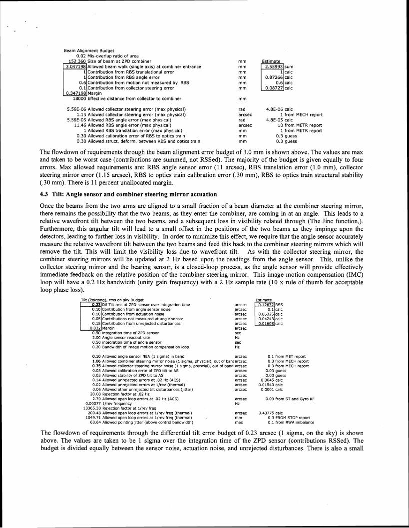
Beam Al ignment Budget 0.02 MIS-overlap rat lo o f area
152.360 Size o f beam a t ZPD combiner m m Est imate Allowed beam wa lk (single axis) a t combiner entrance Contribution f r o m RBS translational error Contribution f r o m RBS angle error m m Contribution f rom mot ion n o t measured by RBS m m
0.1 Con t r~bu t ion f rom collector steering error 1 0 . 3 4 7 1 9 8 l ~ a r g i n
18000 Effective distance f r o m collector t o combiner
5.56E-06 Allowed collector steering error (max physical) 1.15 Allowed collector steerlng error (max physical)
5.56E-05 Allowed RBS angle error ( m a x physical) 11.46 Allowed RBS angle error ( m a x physical)
1 Allowed RBS translation error (max physical) 0.30 Allowed calibration error o f RBS t o optics t ra in 0.30 Allowed struct. deform. between RBS and optics t ra in
rad 4.8E-06 calc arcsec 1 f r o m MECH report rad 4.8E-05 calc arcsec 1 0 f r o m METR report m m 1 f r o m METR report m m 0.3 guess m m 0 .3 guess
The flowdown of requirements through the beam alignment error budget of 3.0 mm is shown above. The values are max and taken to be worst case (contributions are summed, not RSSed). The majority of the budget is given equally to four errors. Max allowed requirements are: RBS angle sensor error (1 1 arcsec), RBS translation error (1.0 mm), collector steering mirror error (1.15 arcsec), RBS to optics train calibration error (.30 mm), RBS to optics train structural stability (.30 mm). There is 1 1 percent unallocated margin.
4.3 Tilt: Angle sensor and combiner steering mirror actuation
Once the beams from the two arms are aligned to a small fraction of a beam diameter at the combiner steering mirror, there remains the possibility that the two beams, as they enter the combiner, are coming in at an angle. This leads to a relative wavefront tilt between the two beams, and a subsequent loss in visibility related through (The Jinc function,). Furthermore, this angular tilt will lead to a small offset in the positions of the two beams as they impinge upon the detectors, leading to further loss in visibility. In order to minimize this effect, we require that the angle sensor accurately measure the relative wavefront tilt between the two beams and feed this back to the combiner steering mirrors which will remove the tilt. This will limit the visibility loss due to wavefront tilt. As with the collector steering mirror, the combiner steering mirrors will be updated at 2 Hz based upon the readings from the angle sensor. This, unlike the collector steering mirror and the bearing sensor, is a closed-loop process, as the angle sensor will provide effectively immediate feedback on the relative position of the combiner steering mirror. This image motion compensation (IMC) loop will have a 0.2 Hz bandwidth (unity gain frequency) with a 2 Hz sample rate (10 x rule of thumb for acceptable loop phase loss).
Contr~but~on from angle sensor nolse Contr~but~on from actuatton nolse
1 0.051~ontr1butions not measured at angle sensor from unrejected disturbances
0.50 lntegratlon tlme of ZPD sensor 2.00 Angle sensor readout rate 0.50 lntegratlon tlme of angle sensor 0.20 Bandw~dth of Image motion compensation loop
Est~mate arcsec arcsec
arcsec sec HZ sec Hz
0.10 Allowed angle sensor NEA ( 1 sigma) In band arcsec 1.06 Allowed comb~ner steerlng mlrror nolse (1 slgma, physclal), out of bancarcsec 0.35 Allowed collector steerlng mlrror nolse ( 1 slgma, physclal), out of band arcsec 0.03 Allowed cal~brat~on error of ZPD tllt to AS arcsec 0.03 Allowed stab~l~ty of ZPD tllt to AS arcsec 0.14 Allowed unrelected errors at .02 Hz (ACS) arcsec 0.02 Allowed unrejected errors at l / rev (thermal) arcsec 0.06 Allowed other unrejected tllt d~sturbances Oltter) arcsec
20.00 Reject~on factor at .02 Hz 2.70 Allowed open loop errors at .02 Hz (ACS) arcsec
0.00077 l l r e v frequency HZ 13365.30 Relection factor at l l r e v freq
200.48 Allowed open loop errors at l l r e v freq (thermal) arcsec 1049.71 Allowed open loop errors at l f rev freq (thermal) mm
63.64 Allowed polntlng jltter (above control bandw~dth) mas
0 .1 from MET report 0.3 from MECH report 0.3 from MECH report
0.03 guess 0.03 guess
0.0045 calc 0.01543 CalC
0.0001 calc
0.09 from ST and Gyro KF
3.43775 calc 0.3 FROM STOP report 0 .1 from RWA Imbalance
The flowdown of requirements through the differential tilt error budget of 0.23 arcsec (1 sigma, on the sky) is shown above. The values are taken to be 1 sigma over the integration time of the ZPD sensor (contributions RSSed). The budget is divided equally between the sensor noise, actuation noise, and unrejected disturbances. There is also a small
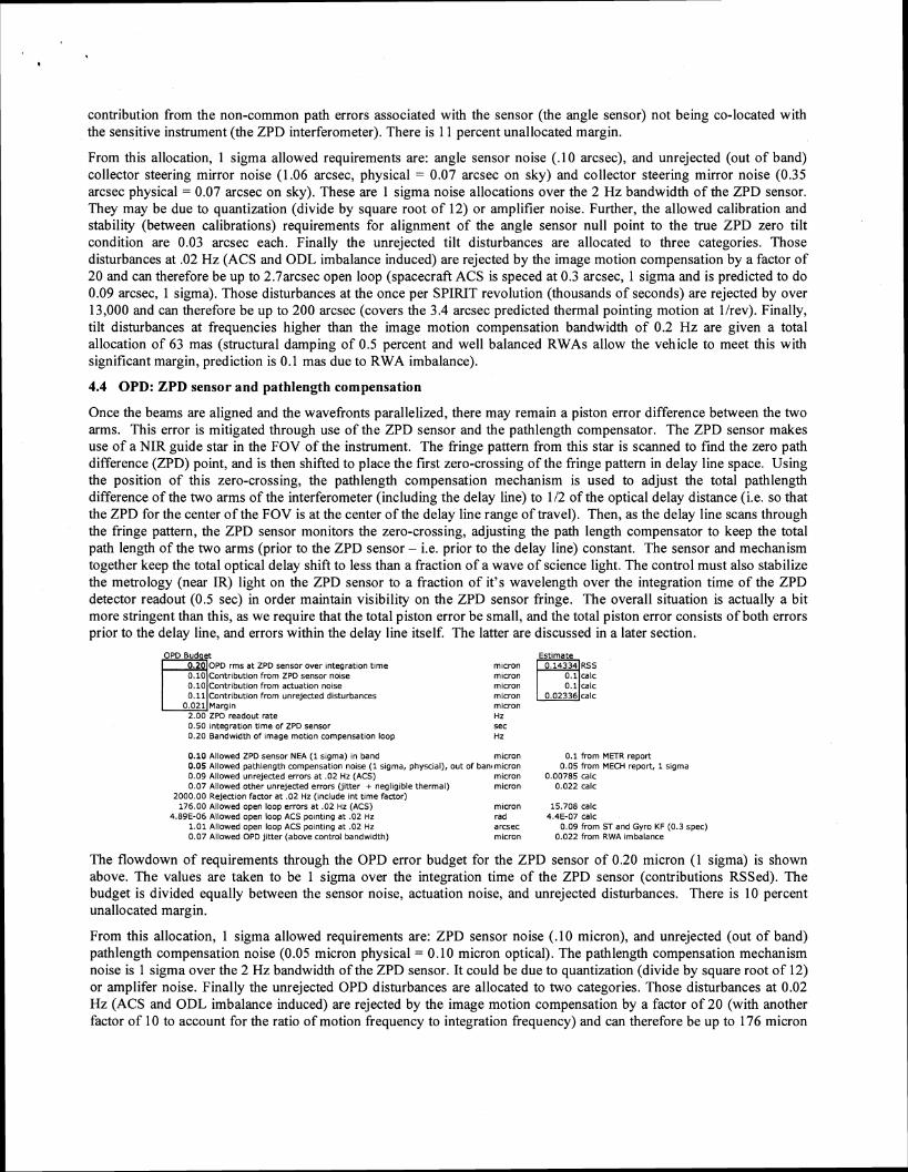
contribution from the non-common path errors associated with the sensor (the angle sensor) not being co-located with the sensitive instrument (the ZPD interferometer). There is 1 1 percent unallocated margin.
From this allocation, 1 sigma allowed requirements are: angle sensor noise ( . lo arcsec), and unrejected (out of band) collector steering mirror noise (1.06 arcsec, physical = 0.07 arcsec on sky) and collector steering mirror noise (0.35 arcsec physical = 0.07 arcsec on sky). These are 1 sigma noise allocations over the 2 Hz bandwidth of the ZPD sensor. They may be due to quantization (divide by square root of 12) or amplifier noise. Further, the allowed calibration and stability (between calibrations) requirements for alignment of the angle sensor null point to the true ZPD zero tilt condition are 0.03 arcsec each. Finally the unrejected tilt disturbances are allocated to three categories. Those disturbances at .02 Hz (ACS and ODL imbalance induced) are rejected by the image motion compensation by a factor of 20 and can therefore be up to 2.7arcsec open loop (spacecraft ACS is speced at 0.3 arcsec, 1 sigma and is predicted to do 0.09 arcsec, 1 sigma). Those disturbances at the once per SPIRIT revolution (thousands of seconds) are rejected by over 13,000 and can therefore be up to 200 arcsec (covers the 3.4 arcsec predicted thermal pointing motion at llrev). Finally, tilt disturbances at frequencies higher than the image motion compensation bandwidth of 0.2 Hz are given a total allocation of 63 mas (structural damping of 0.5 percent and well balanced RWAs allow the vehicle to meet this with significant margin, prediction is 0.1 mas due to RWA imbalance).
4.4 OPD: ZPD sensor and pathlength compensation
Once the beams are aligned and the wavefronts parallelized, there may remain a piston error difference between the two arms. This error is mitigated through use of the ZPD sensor and the pathlength compensator. The ZPD sensor makes use of a NIR guide star in the FOV of the instrument. The fringe pattern from this star is scanned to find the zero path difference (ZPD) point, and is then shifted to place the first zero-crossing of the fringe pattern in delay line space. Using the position of this zero-crossing, the pathlength compensation mechanism is used to adjust the total pathlength difference of the two arms of the interferometer (including the delay line) to 112 of the optical delay distance (i.e. so that the ZPD for the center of the FOV is at the center of the delay line range of travel). Then, as the delay line scans through the fringe pattern, the ZPD sensor monitors the zero-crossing, adjusting the path length compensator to keep the total path length of the two arms (prior to the ZPD sensor - i.e. prior to the delay line) constant. The sensor and mechanism together keep the total optical delay shift to less than a fraction of a wave of science light. The control must also stabilize the metrology (near IR) light on the ZPD sensor to a fraction of it's wavelength over the integration time of the ZPD detector readout (0.5 sec) in order maintain visibility on the ZPD sensor fringe. The overall situation is actually a bit more stringent than this, as we require that the total piston error be small, and the total piston error consists of both errors prior to the delay line, and errors within the delay line itself. The latter are discussed in a later section.
OPD Bud et 0.2 OPD rms at ZPD sensor over lntegratlon tlme
C c o n t r i b u t t o n from ZPD sensor noise I 0.10I~ontributlon from actuation nose
0.11 Contribut~on from unrejected disturbances 0.021 Margin u
2.00 ZPD readout rate 0.50 inteqratlon tlme of ZPD sensor
mlcron mlcron mlcron mlcron mlcron HZ sec
0.20 ~ a n d w ~ d t h of ~mage motlon compensation loop Hz
0.10 Allowed ZPD sensor NEA ( I slgma) In band 0.05 Allowed pathlength compensatlon nolse ( 1 slgma, physclal), c 0.09 Allowed unrejected errors at .02 Hz (ACS) 0.07 Allowed other unrejected errors (ytter + negllg~ble thermal)
2000.00 Rejection factor at .02 Hz (~nclude Int tlme factor) 176.00 Allowed open loop errors at .02 Hz (ACS)
4.89E-06 Allowed open loop ACS polntlng at .02 Hz 1.01 Allowed open loop ACS polntlng at .02 Hz 0.07 Allowed OPD l i t ter (above control bandw~dth)
mlcron ' bani mzcron
mlcron rnlcron
mlcron rad arcsec mlcron
0.1 from METR report 0.05 from MECH report, 1 slgma
0.00785 calc 0.022 calc
15.708 calc 4.4E-07 calc
0.09 from ST and Gyro KF (0.3 spec) 0.022 from RWA ~mbalance
The flowdown of requirements through the OPD error budget for the ZPD sensor of 0.20 micron (1 sigma) is shown above. The values are taken to be 1 sigma over the integration time of the ZPD sensor (contributions RSSed). The budget is divided equally between the sensor noise, actuation noise, and unrejected disturbances. There is 10 percent unallocated margin.
From this allocation, 1 sigma allowed requirements are: ZPD sensor noise ( . lo micron), and unrejected (out of band) pathlength compensation noise (0.05 micron physical = 0.10 micron optical). The pathlength compensation mechanism noise is 1 sigma over the 2 Hz bandwidth of the ZPD sensor. It could be due to quantization (divide by square root of 12) or amplifer noise. Finally the unrejected OPD disturbances are allocated to two categories. Those disturbances at 0.02 Hz (ACS and ODL imbalance induced) are rejected by the image motion compensation by a factor of 20 (with another factor of 10 to account for the ratio of motion frequency to integration frequency) and can therefore be up to 176 micron
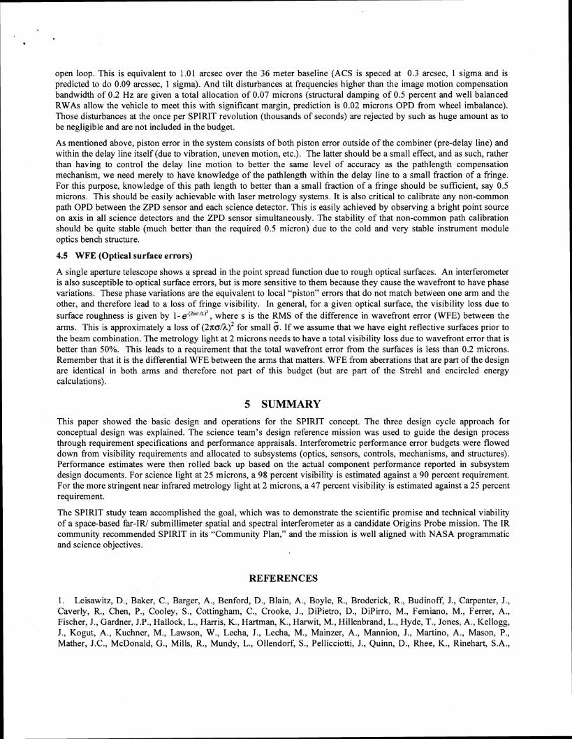
open loop. This is equivalent to 1.01 arcsec over the 36 meter baseline (ACS is speced at 0.3 arcsec, 1 sigma and is predicted to do 0.09 arcssec, 1 sigma). And tilt disturbances at frequencies higher than the image motion compensation bandwidth of 0.2 Hz are given a total allocation of 0.07 microns (structural damping of 0.5 percent and well balanced RWAs allow the vehicle to meet this with significant margin, prediction is 0.02 microns OPD from wheel imbalance). Those disturbances at the once per SPIRIT revolution (thousands of seconds) are rejected by such as huge amount as to be negligible and are not included in the budget.
As mentioned above, piston error in the system consists of both piston error outside of the combiner (pre-delay line) and within the delay line itself (due to vibration, uneven motion, etc.). The latter should be a small effect, and as such, rather than having to control the delay line motion to better the same level of accuracy as the pathlength compensation mechanism, we need merely to have knowledge of the pathlength within the delay line to a small fraction of a fringe. For this purpose, knowledge of this path length to better than a small fraction of a fringe should be sufficient, say 0.5 microns. This should be easily achievable with laser metrology systems. It is also critical to calibrate any non-common path OPD between the ZPD sensor and each science detector. This is easily achieved by observing a bright point source on axis in all science detectors and the ZPD sensor simultaneously. The stability of that non-common path calibration should be quite stable (much better than the required 0.5 micron) due to the cold and very stable instrument module optics bench structure.
4.5 WFE (Optical surface errors)
A single aperture telescope shows a spread in the point spread function due to rough optical surfaces. An interferometer is also susceptible to optical surface errors, but is more sensitive to them because they cause the wavefront to have phase variations. These phase variations are the equivalent to local "piston" errors that do not match between one arm and the other, and therefore lead to a loss of fringe visibility. In general, for a given optical surface, the visibility loss due to surface roughness is given by 1- e-(2"'A)2, where s is the RMS of the difference in wavefront error (WFE) between the arms. This is approximately a loss of ( 2 ? ~ o / h ) ~ for small 6 . If we assume that we have eight reflective surfaces prior to the beam combination. The metrology light at 2 microns needs to have a total visibility loss due to wavefront error that is better than 50%. This leads to a requirement that the total wavefront error from the surfaces is less than 0.2 microns. Remember that it is the differential WFE between the arms that matters. WFE from aberrations that are part of the design are identical in both arms and therefore not part of this budget (but are part of the Strehl and encircled energy calculations).
5 SUMMARY This paper showed the basic design and operations for the SPIRIT concept. The three design cycle approach for conceptual design was explained. The science team's design reference mission was used to guide the design process through requirement specifications and performance appraisals. Interferometric performance error budgets were flowed down from visibility requirements and allocated to subsystems (optics, sensors, controls, mechanisms, and structures). Performance estimates were then rolled back up based on the actual component performance reported in subsystem design documents. For science light at 25 microns, a 98 percent visibility is estimated against a 90 percent requirement. For the more stringent near infrared metrology light at 2 microns, a 47 percent visibility is estimated against a 25 percent requirement.
The SPIRIT study team accomplished the goal, which was to demonstrate the scientific promise and technical viability of a space-based far-IRI submillimeter spatial and spectral interferometer as a candidate Origins Probe mission. The IR community recommended SPIRIT in its "Community Plan," and the mission is well aligned with NASA programmatic and science objectives.
REFERENCES
1. Leisawitz, D., Baker, C., Barger, A., Benford, D., Blain, A., Boyle, R., Broderick, R., Budinoff, J., Carpenter, J., Caverly, R., Chen, P., Cooley, S., Cottingham, C., Crooke, J., DiPietro, D., DiPirro, M., Femiano, M., Ferrer, A., Fischer, J., Gardner, J.P., Hallock, L., Harris, K., Hartman, K., Harwit, M., Hillenbrand, L., Hyde, T., Jones, A., Kellogg, J., Kogut, A., Kuchner, M., Lawson, W., Lecha, J., Lecha, M., Mainzer, A., Mannion, J., Martino, A., Mason, P., Mather, J.C., McDonald, G., Mills, R., Mundy, L., Ollendorf, S., Pellicciotti, J., Quinn, D., Rhee, K., Rinehart, S.A.,
Sauenvine, T., Silverberg, R.F., Smith, T., Stacey, G., Stahl, H.P., Staguhn, J., Tompkins, S., Tveekrem, J., Wall, S., and Wilson, M., The Space Infrared Interferometric Telescope (SPIRIT): High-resolution imaging and spectroscopy in the far-infrared, J. Adv. Sp. Res., in press (2007), doi:10.1016/j.asr.2007.05.081 2. Wilson, M.E., Leisawitz, D.T., Martino, A.J., Rinehart, S.A., Crooke, J.A., Tveekrem, J.L., Budinoff, J.G., Quijada, M.A., and Hyde, T.T., The Space Infrared Interferometric Telescope (SPIRIT): Optical system design considerations, Proc. SPIE 6687, this volume (2007). 3. Budinoff, J.G., Leisawitz, D.T., Rinehart, S.A., DiPirro, M.J., Jones, D.L., Hyde, T.T., and Taylor, B., Mechanical design of the Space Infrared Interferometric Telescope (SPIRIT), Proc. SPIE 6687, this volume (2007). 4. DiPirro, M.J., Cottingham, C., Boyle, R., Ollendorf, S., and Leisawitz, D.T., The SPIRIT thermal system, Proc. SPIE 6687, this volume (2007). 5. Benford, D.J., Rinehart, S.A., Hyde, T.T., and Leisawitz, D.T., Cryogenic far-infrared detectors for the Space Infrared Interferometric Telescope (SPIRIT), Proc. SPIE 6687, this volume (2007). 6. Rinehart, S.A., Armstrong, J.T., Frey, B.J., Jung, J., Kirk, J. , Leisawitz, D.T., Leviton, D.B., Lyon, R.G., Martino, A.J., Mundy, L.G., Pauls, T.A., and Schurr, S., Wide-field imaging interferometry: An enabling technique for high angular resolution astronomy, Proc. SPIE 6687, this volume (2007). 7. Martino, A.J., Leisawitz, D.T., Thompson, A.K., Rinehart, S.A., and Frey, B.J., An optical model of the Wide-field Imaging Interferometry Testbed, Proc. SPIE 6687, this volume (2007)