System Design Review. Team Members: ◦ Pattie Schiotis – Team Manager (ME) ◦ Shane Reardon –...
30
P13002: Ankle-Foot Orthotic Un-Tethered, Mechanical System Design Review
-
Upload
clarissa-boone -
Category
Documents
-
view
220 -
download
1
Transcript of System Design Review. Team Members: ◦ Pattie Schiotis – Team Manager (ME) ◦ Shane Reardon –...

P13002: Ankle-Foot Orthotic Un-Tethered, Mechanical
System Design Review

Team Members:◦ Pattie Schiotis – Team Manager (ME)◦ Shane Reardon – Lead Engineer (ME)◦ Dana Kjolner (EE)◦ Robert Ellsworth (EE)◦ Sam Hosig (CE)◦ John Williams (CE)
•Faculty Guide: Dr. DeBartolo
The Team

Introduction Work Breakdown Structure Customer Needs Engineering Specifications Functional Decomposition Concepts Component Benchmarking Risk Assessment MSD I Project Plan
Agenda
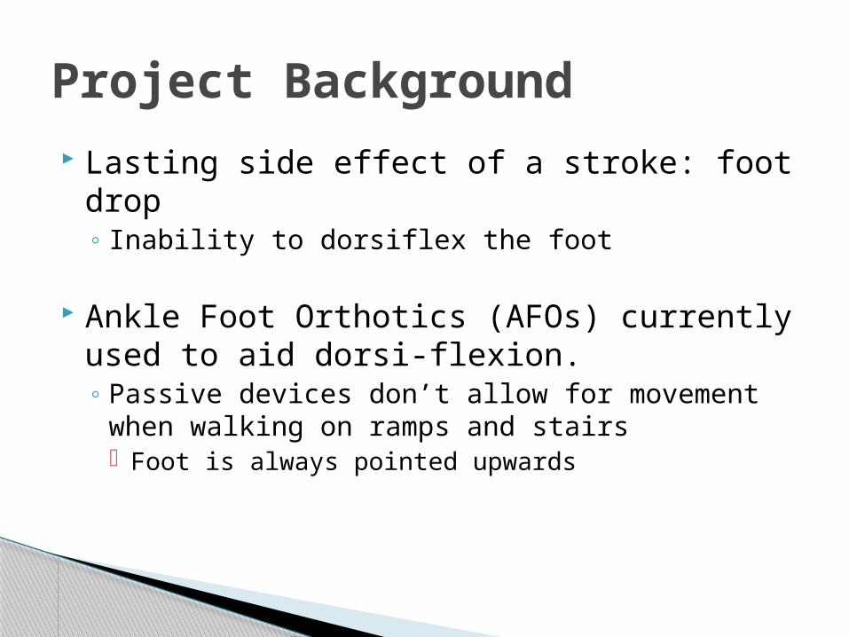
Lasting side effect of a stroke: foot drop◦ Inability to dorsiflex the foot
Ankle Foot Orthotics (AFOs) currently used to aid dorsi-flexion.◦ Passive devices don’t allow for movement when
walking on ramps and stairs Foot is always pointed upwards
Project Background

User will have no ability to either plantar-flex or dorsi-flex their foot
Side to side stability of the foot will be ignored
Worst case will be analyzed:◦ 95 percentile male having heavy foot.◦ Fast walker – gait cycle less than 1 second.
Device may not use air muscles as an actuation source
Assumptions & Constraints

Work Breakdown Structure

Key Customer NeedsPrimary Needs: Secondary Needs:
Safety Portable
◦ Lasts all day without charging/refueling
◦ Lightweight◦ Tolerable to wear all day
Reliable Accommodates Flat Terrain Accommodates Special
Terrain◦ Stairs◦ Ramps◦ Obstacles
Comfortable◦ Aesthetically Pleasing
Durable◦ Water Resistant◦ Corrosion Resistant
Salt & Environment Biocompatibility
Convenient◦ Easy to put on and take
off

Key Engineering Specifications
Engineering Specification
Number
Engineering Specification Description
Units of Measure
Preferred Direction
Nominal Value
Method of Validation
Stems From Customer Need
s1 torque on Foot N-m Up ≥±3.0 Test FT1,2,4,ST1,5
s2 system response time (sensing terrain to actuating device) ms down <400 Test ST3
s4 predicts step down yes/no - yes Test ST1,2,4s5 predict flat yes/no - yes Test FT1,ST5s7 predicts ramp down yes/no - yes Test ST1,2,4
s10 allowable range of motion between foot and shin degrees range 70 to 135 Test FT1,3,CF8,9,ST1
s12 untethered usage time hrs/steps up 8 hrs or 3000 steps P1,2,D1
s17 force to secure constraints N down < 80 Test C4s18 force to remove constraints N down < 80 Test C3s23 radius of edges/corners on AFO mm up 0.5 - S4,CF1,2s24 weight of entire device kg down ≤3 Test FT6
s28 Operates in environment temperature range °C range -17.8 to
37.8Component
Ratings D2
s31 Minimum life until failure steps up 5.5 million test D1
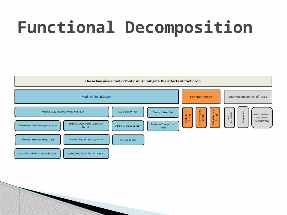
Functional Decomposition

Concept Generation Table

Mechanical Locking MethodUses a solenoid to unlock the heel which allows the foot to drop.
Design Option 1

Mechanical Locking Method◦ Mechanically restrict the foot from dorsi/plantar
flexing while in the air.◦ Use gravity to help the foot plantar-flex as
needed (stairs/ramps)◦ Methods:
1. Use a solenoid to unlock the heel which allows the foot to drop.
2. Use a brake to unlock the heel which allows the foot to drop. 3. Ratcheting Device attached to ankle
Design Option 1

Design Option 2 Active Actuation
◦ Uses a linear actuator to force the foot into the proper position.
◦ Methods: Solenoid Piezoelectric Power Screw Hybrid
Power Screw with electric motor

Hard StopTwo preset distances can be moved back and forth usinga servo motor and screw.
Design Option 3
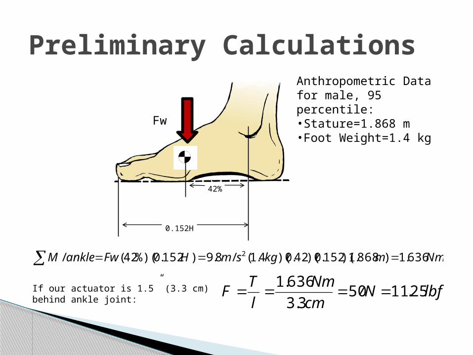
Preliminary Calculations
42%
0.152H
Fw
NmmkgsmHFwankleM 636.1)868.1)(152.0)(42.0)(4.1(/8.9)152.0%)(42(/ 2
lbfNcm
Nm
l
TF 25.1150
3.3
636.1If our actuator is 1.5” (3.3 cm) behind
ankle joint:
Anthropometric Data for male, 95 percentile:•Stature=1.868 m•Foot Weight=1.4 kg

Calculations Continued
θ=20°
cmly 28.1)20sin(3.3sin
Dorsi-flexion:
Plantar-flexion:
cmly 33.2)45sin(3.3sin
Total stroke=3.61 cmIn 0.4s, we need 9 cm/s

Active Actuation Sources
Solenoid Electro-Mechanical PiezoelectricActuation Force 30 lbs 22 lbs 100NStroke 1.1 cm >4.4 cm micro-metersSpeed <100 ms 10 cm/s -Power Consumption 92V, 7.2 A (moving), 0.08 A (holding) 12VDC, 5 A 100 V
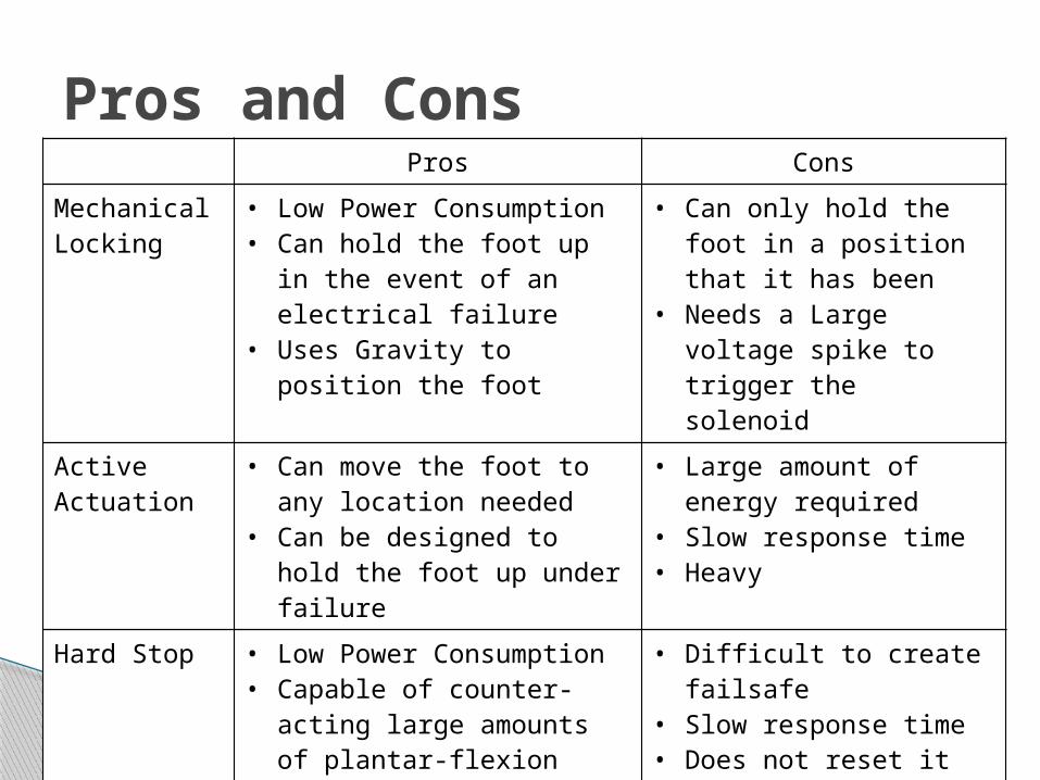
Pros and ConsPros Cons
Mechanical Locking
• Low Power Consumption• Can hold the foot up in the
event of an electrical failure
• Uses Gravity to position the foot
• Can only hold the foot in a position that it has been
• Needs a Large voltage spike to trigger the solenoid
Active Actuation
• Can move the foot to any location needed
• Can be designed to hold the foot up under failure
• Large amount of energy required
• Slow response time• Heavy
Hard Stop • Low Power Consumption• Capable of counter-acting
large amounts of plantar-flexion force
• Difficult to create failsafe
• Slow response time• Does not reset it self
when the toes need to be pointed up

Concept Selection Matrix
Concepts
A B C D Mechanical
LockingActive
ActuationHard Stop Passive
Device
Selection Criteria Weight Rating Weighted Score Rating Weighted
Score Rating Weighted Score Rating Weighted
Score
Safety 20% 2 0.4 1 0.2 1 0.2 1 0.2
Portable 15% 2 0.3 0 0 3 0.45 3 0.45
Reliable 15% 2 0.3 3 0.45 1 0.15 2 0.3
Accommodates Flat Terrain 15% 2 0.3 1 0.15 1 0.15 1 0.15
Accommodates Special Terrain 15% 3 0.45 1 0.15 2 0.3 0 0
Comfortable 8% 1 0.08 0 0 2 0.16 1 0.08
Durable 8% 1 0.08 1 0.08 2 0.16 2 0.16
Removability 4% 2 0.08 2 0.08 3 0.12 2 0.08
Total Score 1.99 1.11 1.69 1.42
Rank 1 4 3 2
Continue? Yes No No N/A

Bounces infrared light off terrain to determine distance
10 cm to 80 cm range Worst case power
consumption per sensor is 0.00176 kWhr
Output from -0.3 to +0.3 volts Highly accurate within
operational ranges Low cost (~$15)
https://www.sparkfun.com/products/242
System Component: Sensors

A Far A Normal A Close
B Far
Mid Stride, Down Slope/ Stairs
Mid Stride, Normal Terrain
Mid Stride,
Up Slope/ Stairs
B Close
Foot Planted, Down Slope/ Stairs
Foot Planted, Normal Terrain
Foot Planted,
Up Slope/ Stairs
IR Distance and Terrain Type
Sensor A
Sensor B
Terrain

Sensor Calibration
Nonlinear response Reflective ratio of
materials is mostly irrelevant
Static position
Concerns about irregular terrain types
https://www.sparkfun.com/products/242

Predicts what type of terrain we are walking on
Calculates where in the gait cycle we are Has some modeling that improves
performance of predictions
NEED TO CHANGE Need to be able to fully implement in C Error checking for invalid states Nothing is done at run-time
Current Code: Developed by Chappy

System Component: Micro Controller

Micro controller needs:◦ Interface with two IR sensors and possible angle
senor ADC
◦ Control actuation method PMW or Digital I/O
◦ Other considerations Must run on battery power for at least 8 hours Must be able to simulate system in “real time” Must be able to fit on orthotic Must be able to export data to sd card if needed
System Component: Micro Controller

Power ConsumptionPower From Micro Controller and Sensors
DeviceTime
(Hours)Current
(A)Voltage
(V)Power
(mWhr) Total Power (mWhr)IR Sensors 8 0.03 5 1200 2400Micro C. 8 3.00E-04 5 12 12
Total Power 241280% Efficiency 2894
Solenoid Power Usage for Option 1Watts per step Time per step mWhr / step
40 0.5 5.5

Risk Assessment
ID Risk Item Effect Cause
Likelihood
Severity
Importance Action to Minimize Risk Owner
1Foot failing in down position User would trip and fall Sensor unable to detect terrain
or send faulty readings2 3 6
Software fail safe, if no data is sensed will fail in natural position
Engineering Lead
2Actuator malfunction
1 2 2System free to move if actuator breaks
Engineering Lead
3
Structural failure, orthotic unable to support equipment
1 3 3
Large enough factor of safety Engineering Lead
4Spring Yielding/Buckling
1 2 2Structural modification, mechanical prevented action
Engineering Lead
5
Power supply
3 2 6
Before system runs out of power, lock in normal state. Warning signal included
Electrical Engineers
6
Scheduled deadlines not met Timeline falls behind, other deadlines change
Personal conflicts: time management, overloads schedule, illness
3 2 6
Communication among members to know each other’s schedules, understand critical path, seek help when needed
Team Manager
7
Material acquisition delay Prototype cannot be built and tested
Long lead times, parts not ordered on time
1 2 2
Contact with vendors, determine parts with long lead times, order by week 7
Team Manager
8
Incorrect material handling Overload system capabilities Misuse of supplies
2 2 4
Responsible team members in charge of their components. Understand system capabilities and specifications
Engineering Lead
9Unable to meet customer specifications
Project failure, unhappy customer
Weight of device too heavy2 3 6
Be cautious of component weights when creating detailed design
Engineering Lead
10Device contains sharp edges, harms the users 1 3 3
Ensure all points of contact will not harm user, no pressure points
Mechanical Engineers
11
Memory overflow Device would go into an error state
Not enough memory on the micro controller and associated memory systems 2 2 4
Ensure enough memory is available on micro controller
Computer Engineers

Project PlanID Task Name Complete (%) Completetion Goal When
Completed Issues/Comments
1 Define Project 2 Review customer needs 90% 10/2/2012 Review after concepts selected3 Review customer specifcations 90% 10/2/2012 Review after concepts selected4 Finalized functional decomposition 100% 9/21/2012 9/21/2012 5 Determine work breakdown structure 100% 10/5/2012 9/28/2012changes after systems review6 Observe walking patterns at naz clinic 100% 9/24/2012 9/24/2012 7 Concept Generation 8 Create benchmark matrix 90% 9/28/2012 9 Define components 100% 9/14/2012 9/28/2012
10 Establish system possibilities 100% 9/14/2012 9/21/2012 11 Create system comparions (Pros and Cons) 100% 9/28/2012 10/2/2012 12 Develop Proposed Design 13 Assign team member specific jobs 100% 9/21/2012 9/21/2012Proposed design approval14 Develop psedeocode 100% 9/28/2012 9/28/2012 15 Review previously developed sensor code 100% 9/28/2012 9/28/2012 16 Feasibility analysis 80% 10/2/2012 17 Compile Systems Design Review 18 Schedule review 100% 9/25/2012 9/28/2012 19 Create risk assessment 100% 10/2/2012 10/2/2012 20 Create review report out 95% 9/28/2012 21 Develop project schedule 90% 10/2/2012 22 Part Selection 23 Select components 40% 10/12/2012 24 Create budget breakdown 0% 10/12/2012 Need component specifications 25 Detail component information (specs, vendor) 5% 10/19/2012 26 Purchase parts 0% 10/26/2012 relient on specs 24-2627 Detailed Design 28 Create BOM 0% 10/19/2012 29 Update risk assessment on going 30 Verify design output 0% 10/23/2012 31 Finalize system architecture 0% 10/16/2012 32 Prepare drawings, schematics, and flow charts 0% 10/26/2012 33 Identify critical design path 0% 10/12/2012 34 Document design changes (if any) 0% 11/10/2012 35 Test Plan 36 Determine component testing 0% 10/26/2012 37 Create testing guide/SOP 0% 11/3/2012 38 Estimate resource requirements 0% 11/10/2012 39 Create data collection sheets 0% 11/10/2012 40 Additional Tasks 41 Update EDGE on going

1. Scope of project is to design a modified AFO that includes: Energy storage medium Foot rotation device Terrain sensing system Microcontroller
2. We will focus on a detailed design following the “Mechanical Locking Mechanism” concept.
Closing Remarks/Comments

Questions?