System Description for the Universal Access …anri.go.id/assets/doc/pidato/UAT-WP-1-09.pdf1-1...
30
1-1 System Description for the Universal Access Transceiver System Proposed for Link Evaluation of the Safe Flight-21 Applications 1 Chris Moody October 1999, Revised November 2000 Introduction This document provides a description of the Universal Access Transceiver (UAT). This document will be used as part of the FAA’s Safe Flight 21 project to evaluate candidate broadcast data links to support situational awareness functions. Section 1 Basic System Characteristics 1.1 Net Access Protocol 1.1.1 Net Management Concept Timing of ADS-B and Ground Message Transmissions Figure 1-1 illustrates the timing structure for UAT message transmissions. In the UAT system, the frame is the most fundamental time unit. Frames are one second long and begin at the start of each UTC (or GPS) second. Each frame is divided into two segments: one segment in which ground message burst transmissions may occur, and another in which ADS-B message burst transmissions may occur. 1 Based on agreed outline within the Tech/Cert subgroup
Transcript of System Description for the Universal Access …anri.go.id/assets/doc/pidato/UAT-WP-1-09.pdf1-1...
1-1
System Description for the Universal Access Transceiver
System Proposed for Link Evaluation of the Safe Flight-21 Applications1
Chris Moody
October 1999, Revised November 2000
Introduction This document provides a description of the Universal Access Transceiver (UAT). This
document will be used as part of the FAA’s Safe Flight 21 project to evaluate candidate broadcast data links to support situational awareness functions.
Section 1
Basic System Characteristics
1.1 Net Access Protocol
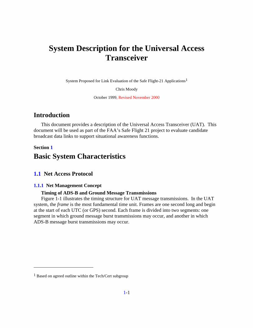
1.1.1 Net Management Concept Timing of ADS-B and Ground Message Transmissions Figure 1-1 illustrates the timing structure for UAT message transmissions. In the UAT
system, the frame is the most fundamental time unit. Frames are one second long and begin at the start of each UTC (or GPS) second. Each frame is divided into two segments: one segment in which ground message burst transmissions may occur, and another in which ADS-B message burst transmissions may occur.
1 Based on agreed outline within the Tech/Cert subgroup

1-2
GroundBroadcast(32 time slots)
UAT Frame = 1 sec.
Aircraft Reports (random)
Ground Message (464 bytes payload) ADS-B Message (16/32 bytes payload)
Figure 1-1. UAT Timing Structure
Each segment is further subdivided into message start opportunities (MSOs) spaced 250 µs apart for a total of 4,000 MSOs per frame. The MSO is the smallest time increment used for scheduling ground message or ADS-B message transmissions.
NOTE: This allows a single fixed tuned airborne transceiver to support full air—air, ground—air, and air—ground connectivity for broadcast applications.
Scheduling of Ground Broadcast message transmissions The ground broadcast segment consists of 752 MSOs, for a total of 188 ms. These 752
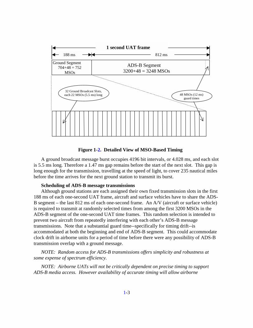
MSOs are divided into 32 ground broadcast slots, each 22 MSOs long, plus a guard interval of 48 MSOs (12 ms). Each ground station is assigned one of the 32 time slots, in such a way that nearby ground stations in range can always be received without interference. Each ground station transmits a ground broadcast message once each second, starting at the start of its assigned slot. Figure 1-2 shows details of the MSO-based timing.
1-3
Ground Segment704+48 = 752
MSOs
ADS-B Segment3200+48 = 3248 MSOs
188 ms
1 second UAT frame812 ms
32 Ground Broadcast Slots,each 22 MSOs (5.5 ms) long 48 MSOs (12 ms)
guard times
Figure 1-2. Detailed View of MSO-Based Timing
A ground broadcast message burst occupies 4196 bit intervals, or 4.028 ms, and each slot is 5.5 ms long. Therefore a 1.47 ms gap remains before the start of the next slot. This gap is long enough for the transmission, travelling at the speed of light, to cover 235 nautical miles before the time arrives for the next ground station to transmit its burst.
Scheduling of ADS-B message transmissions Although ground stations are each assigned their own fixed transmission slots in the first
188 ms of each one-second UAT frame, aircraft and surface vehicles have to share the ADS-B segment – the last 812 ms of each one-second frame. An A/V (aircraft or surface vehicle) is required to transmit at randomly selected times from among the first 3200 MSOs in the ADS-B segment of the one-second UAT time frames. This random selection is intended to prevent two aircraft from repeatedly interfering with each other’s ADS-B message transmissions. Note that a substantial guard time--specifically for timing drift--is accommodated at both the beginning and end of ADS-B segment. This could accommodate clock drift in airborne units for a period of time before there were any possibility of ADS-B transmission overlap with a ground message.
NOTE: Random access for ADS-B transmissions offers simplicity and robustness at some expense of spectrum efficiency.
NOTE: Airborne UATs will not be critically dependent on precise timing to support ADS-B media access. However availability of accurate timing will allow airborne
1-4
transceivers to perform a passive range validation of ADS-B reports as described in Section 2.1.2.2.1.
1.1.2 End State Protocol The description in 1.1.1 above represents the proposed net access protocol in an end state
configuration.
1.1.3 Relationship of Test Circumstance to End State
1.1.3.1 Access Protocol The description in 1.1.1 above represents the net access protocol implemented in the test
configuration and is also consistent with that of the proposed operational system.
1.1.3.2 Backup Timing Test units do not support the backup timing of the airborne UAT from receipt of ground
broadcast messages. It is expected that “end state” units could however support this function in order to maintain transmitter timing in the event of GPS outage. The primary benefit of this backup timing information is that independent ADS-B range validation can continue to be supported.
1.2 Waveform
1.2.1 Channel Frequency(s) and Modulation Technique The UAT transceiver operates on an experimental frequency assignment of 966 MHz.
Rationale—Use of a single common global channel is the simplest architecture for supporting ADS-B since seamless air-air operation is required. As a result, the channel should offer significant bandwidth to assure adequate capacity and performance. This band was selected due to the wide channelization (1 MHz) that currently exists there and the potential availability of certain channels that could be reserved on a global basis. However, the system is not frequency specific and could operate in any suitable spectrum.
Data shall be modulated onto the carrier using binary Continuous Phase Frequency Shift Keying. The modulation index, h, shall be 0.6; this implies that if the data rate is Rb, then the nominal frequency separation between “mark” (binary 1) and “space” (binary 0) is ∆f = h • Rb. A binary 1 is indicated by a shift up in frequency from the nominal carrier frequency of ∆f/2 and a binary 0 by a shift of -∆f/2.
The signal shall be filtered to give a reasonably compact frequency spectrum. (The “mask” specifying the bandwidth occupied by the signal is TBD.) This filtering may be done
1-5
either at the baseband waveform prior to modulation, or on the modulated signal, or both, as necessary.
Rationale—This modulation scheme permits relatively simple, inexpensive nonlinear transmitter and receiver implementations. It also offers a relatively high tolerance to self-interference.
1.2.2 Channel Rate and Bit Structure The modulation rate is 1.041667 megabit/second. This rate, coupled with the modulation
index of h = 0.6, would imply that ∆f = 625 kHz, and that the deviation from the carrier frequency is ±312 kHz. (In practice, however, because the filtering for bandwidth limitation introduces some overshoot in the deviation, the maximum deviation is closer to ±450 kHz.)
1.2.3 Synchronization and Preamble Characteristics
1.2.3.1 Preamble Sequences To allow for receiver stabilization and to minimize transient spectral components, the
transmitter power shall ramp up and down at the start and end of each burst. The maximum time duration of these ramps shall be no more than 4 bit periods each. Ramp time is defined as the time between 90 per cent power output and –60 dB power output. During ramp up and down, the modulating data shall be all zeroes.
Following ramp up, each data burst will include a 36 bit synchronization sequence. For the ADS-B messages (from aircraft) the sequence will be
111010101100110111011010010011100010
with the left-most bit transmitted first.
For ground broadcast messages, the polarity of the bits of the synchronization sequence is reversed, that is, the ones and zeroes are interchanged. This synchronization sequence is
000101010011001000100101101100011101.
NOTE: Because of the close relationship between the two synchronization sequences, the same correlator can search for both simultaneously.
NOTE: These sequences were selected for their good autocorrelation properties.
1.2.3.2 Preamble Retrigger Preamble retrigger allows the receiver to perform the sync detection process on multiple
messages simultaneously in the event of message overlap—in particular when a stronger message follows a weaker one. Test units do not incorporate this function, but it is expected
1-6
that end state units would support this to fully exploit the “capture effect” of the waveform in cases where a stronger ADS-B message overlapped a previous weaker one.
1.2.4 Message Structure and Coding
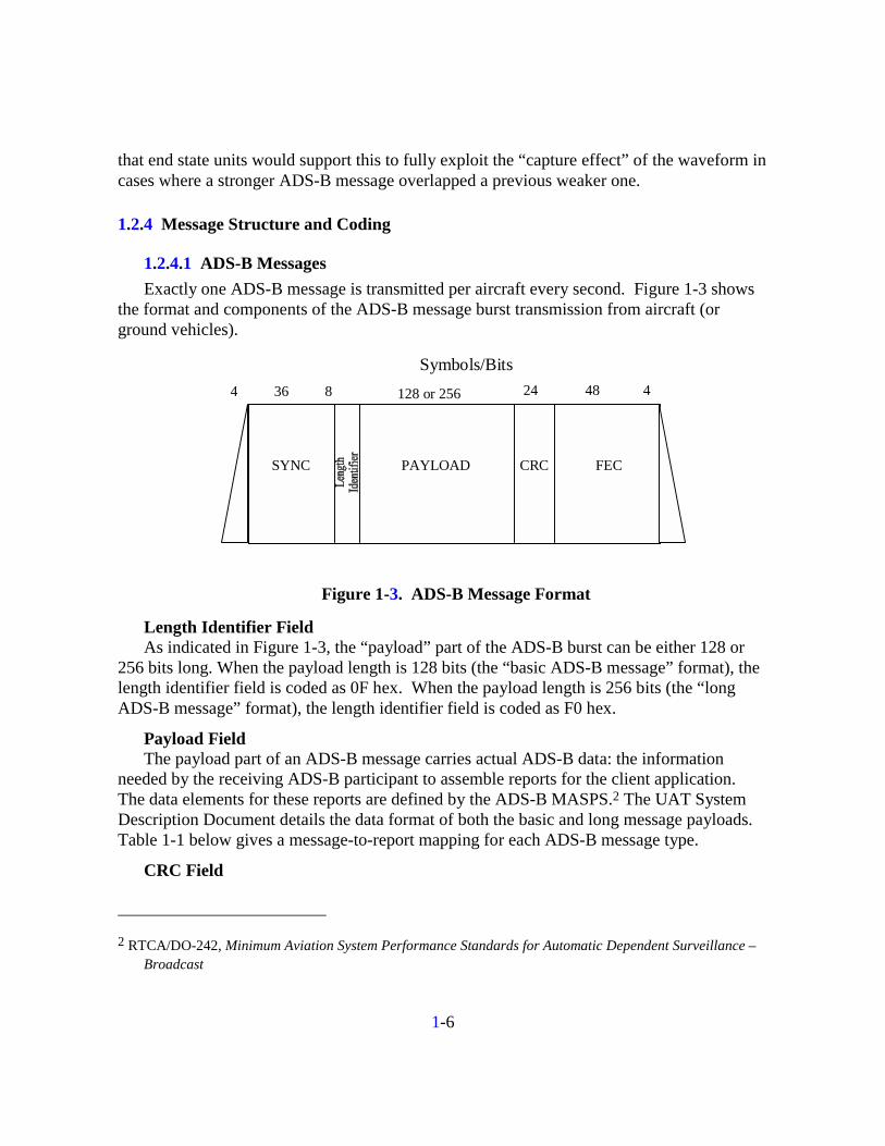
1.2.4.1 ADS-B Messages Exactly one ADS-B message is transmitted per aircraft every second. Figure 1-3 shows
the format and components of the ADS-B message burst transmission from aircraft (or ground vehicles).
Symbols/Bits4 36 8
SYNC PAYLOAD CRC FEC
24 48 4128 or 256
Figure 1-3. ADS-B Message Format
Length Identifier Field As indicated in Figure 1-3, the “payload” part of the ADS-B burst can be either 128 or
256 bits long. When the payload length is 128 bits (the “basic ADS-B message” format), the length identifier field is coded as 0F hex. When the payload length is 256 bits (the “long ADS-B message” format), the length identifier field is coded as F0 hex.
Payload Field The payload part of an ADS-B message carries actual ADS-B data: the information
needed by the receiving ADS-B participant to assemble reports for the client application. The data elements for these reports are defined by the ADS-B MASPS.2 The UAT System Description Document details the data format of both the basic and long message payloads. Table 1-1 below gives a message-to-report mapping for each ADS-B message type.
CRC Field
2 RTCA/DO-242, Minimum Aviation System Performance Standards for Automatic Dependent Surveillance –
Broadcast

1-7
Following the payload is a 24-bit cyclic redundancy check (CRC) code. The particular code used is the CRC-24Q code, for which the generating polynomial is
GP(x) = x24 + x23 + x18 + x17 + x11 + x10 + x7 + x6 + x5 + x4 + x3 + x + 1.
The CRC acts as a 24-bit parity code, generated from the 128-bit or 256-bit payload by a certain algorithm. With a 24-bit parity code, the probability of not detecting a corrupted payload is approximately 2-24, or 5.96 × 10⁻⁸.
FEC Field After the CRC comes a 48-bit FEC (Forward Error Correcting code) field using a Reed-
Solomon (RS) code. The purpose of this field is to permit the (payload + CRC) data to be transmitted reliably over the air; as an error-correcting code, the FEC permits “bad data bits” (data bits corrupted by noise or interference) to be corrected. This correction process has a certain (low) probability of generating an incorrectly “corrected” bit sequence. If this should occur, the CRC code will permit the detection of that incorrect data. The result of this dual error detection process (error detection and correction using the FEC field, followed by the detection of remaining errors using the CRC field) will be to ensure, with a very high level of confidence, that no bit error will go undetected.
The (payload + CRC + FEC) group of fields may be termed a “Reed-Solomon block” – a sequence of data bits (payload + CRC) together with the FEC Reed-Solomon code that protects those data bits against corruption.
NOTE: This will allow correction of any 3, 8 bit words in the Reed-Solomon block.

1-7
Table 1-1. ADS-B Message Burst to Report Element Mapping
Elem
ent D
escr
iptio
n
ICAO
Add
r.
Latit
ude
Long
itude
Alt.
(Geo
)
NU
Cp
Geo
. Pos
. Val
id
N. V
eloc
ity
E. V
eloc
ity
Vert.
Rat
e (G
eo)
NU
C R
Alt.,
(Bar
o)
Baro
Alt.
Rat
e
Airs
peed
Gnd
Spd
, Gnd
Trk
Turn
Indi
cato
r
Tim
e of
App
licab
ility
Rep
ort M
ode
ICAO
Add
ress
Cal
l Sig
n
Cat
egor
y
Surv
. Sup
port
Emrg
/Prio
rity
Stat
us
Appl
. Cla
ss C
ode
TCP
Latit
ude
TCP
Long
itude
TCP
Altit
ude
Tim
e to
Go
Opn
Mod
e Sp
ecifi
c D
ata
Flt M
ode
Spec
ific
Dat
a
Tim
e of
App
licab
ility
ICAO
Add
ress
TCP+
1 La
titud
e
TCP+
1 Lo
ngitu
de
TCP+
1 Al
titud
e
TCP+
1 Ti
me
to G
o
Spar
e or
Oth
er
Tota
l Pay
load
Bits
RF Burst/Msg Type
Basic 25 24 24 4 1 11 11 4 12 9 * N/A N/A 3 128Type 0 Extended 25 24 24 13 4 1 11 11 8 4 12 9 12 2 * N/A 43 5 3 12 N/A 33 256
Basic** 25 24 24 4 1 11 11 4 12 9 * N/A N/A 3 128Type 0 Extended 25 24 24 13 4 1 11 11 8 4 12 9 12 2 * N/A 43 5 3 12 N/A 33 256Type 1 Extended 25 24 24 4 1 11 11 4 12 9 * N/A 20 20 12 12 N/A 20 20 12 12 3 256Type 2 Extended 25 24 24 4 11 11 4 12 9 2 * N/A <130 bits for future definition> N/A 130 256
* Time of applicability is implicit and tied to the UTC second prior to transmission
** Full capability participant would not use the Basic Message
On Cond'n (OC)State Vector (SV) Elements Mode Status (MS) Elements Elements
Ope
ratio
nal S
yste
Ave
rage
per
Airc
raft
Bro
adca
st R
ate
(hz)
0.250.5
Eval
uatio
n U
nits
0.25
0.60.2
1-8
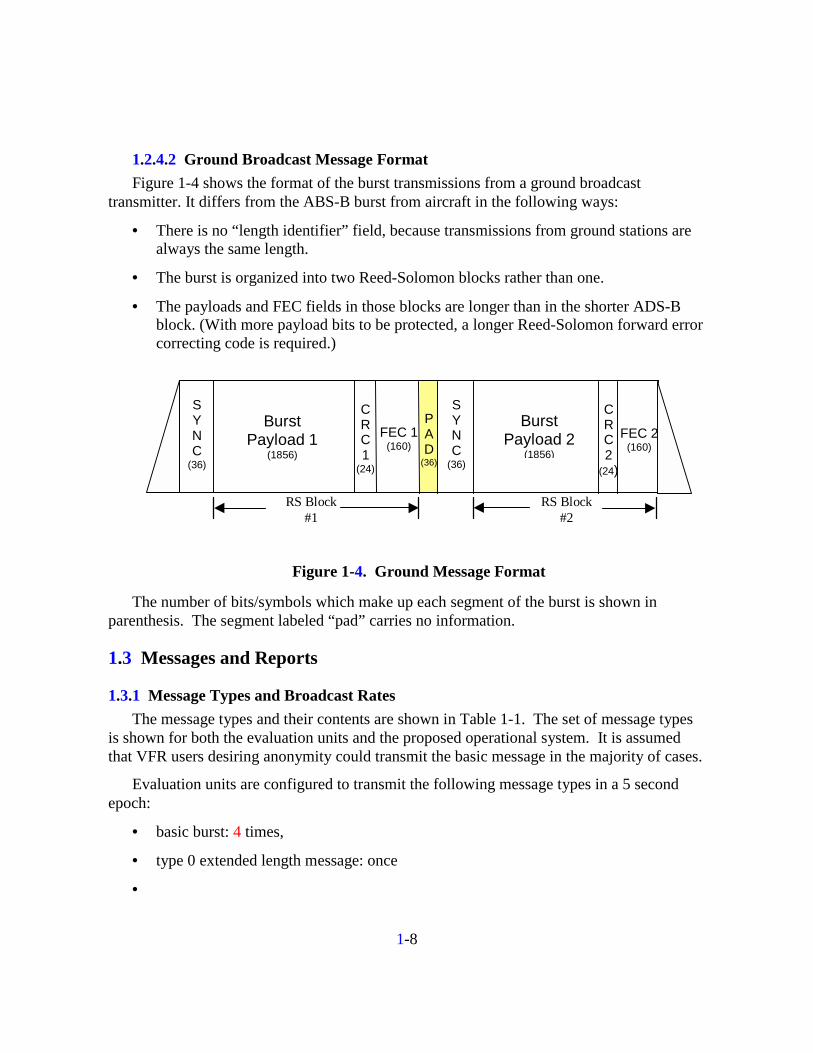
1.2.4.2 Ground Broadcast Message Format Figure 1-4 shows the format of the burst transmissions from a ground broadcast
transmitter. It differs from the ABS-B burst from aircraft in the following ways:
• There is no “length identifier” field, because transmissions from ground stations are always the same length.
• The burst is organized into two Reed-Solomon blocks rather than one.
• The payloads and FEC fields in those blocks are longer than in the shorter ADS-B block. (With more payload bits to be protected, a longer Reed-Solomon forward error correcting code is required.)
SYNC
(36)
BurstPayload 1
(1856)
CRC1
(24)
FEC 1(160)
PAD
(36)
SYNC
(36)
BurstPayload 2
(1856)
CRC2
(24)
FEC 2(160)
RS Block#1
RS Block#2
Figure 1-4. Ground Message Format
The number of bits/symbols which make up each segment of the burst is shown in parenthesis. The segment labeled “pad” carries no information.
1.3 Messages and Reports
1.3.1 Message Types and Broadcast Rates The message types and their contents are shown in Table 1-1. The set of message types
is shown for both the evaluation units and the proposed operational system. It is assumed that VFR users desiring anonymity could transmit the basic message in the majority of cases.
Evaluation units are configured to transmit the following message types in a 5 second epoch:
• basic burst: 4 times,
• type 0 extended length message: once
•
1-9
In the proposed operational system, it is expected that message transmissions would rotate through the set of 3 extended length message types in sequence through a 4 second epoch as shown in Table 1-1 for the operational system. This assumes a full capability participant; others could make some use of the Basic Message.
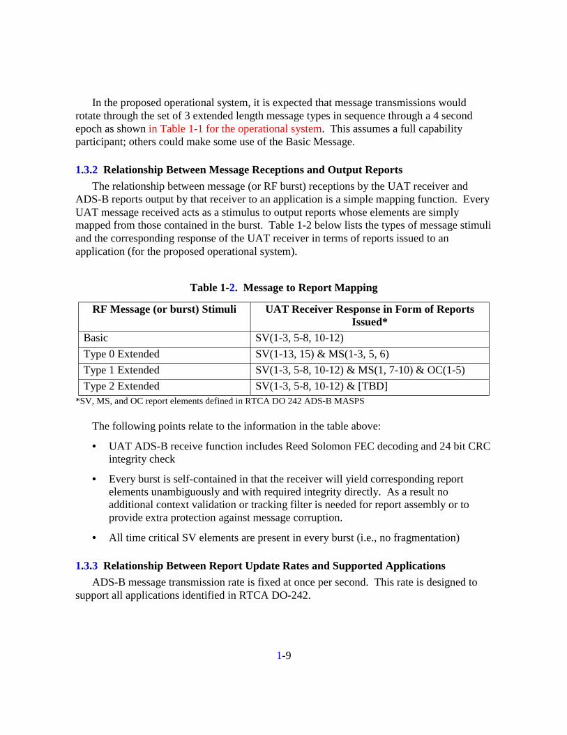
1.3.2 Relationship Between Message Receptions and Output Reports The relationship between message (or RF burst) receptions by the UAT receiver and
ADS-B reports output by that receiver to an application is a simple mapping function. Every UAT message received acts as a stimulus to output reports whose elements are simply mapped from those contained in the burst. Table 1-2 below lists the types of message stimuli and the corresponding response of the UAT receiver in terms of reports issued to an application (for the proposed operational system).
Table 1-2. Message to Report Mapping
RF Message (or burst) Stimuli UAT Receiver Response in Form of Reports Issued*
Basic SV(1-3, 5-8, 10-12) Type 0 Extended SV(1-13, 15) & MS(1-3, 5, 6) Type 1 Extended SV(1-3, 5-8, 10-12) & MS(1, 7-10) & OC(1-5) Type 2 Extended SV(1-3, 5-8, 10-12) & [TBD]
*SV, MS, and OC report elements defined in RTCA DO 242 ADS-B MASPS The following points relate to the information in the table above:
• UAT ADS-B receive function includes Reed Solomon FEC decoding and 24 bit CRC integrity check
• Every burst is self-contained in that the receiver will yield corresponding report elements unambiguously and with required integrity directly. As a result no additional context validation or tracking filter is needed for report assembly or to provide extra protection against message corruption.
• All time critical SV elements are present in every burst (i.e., no fragmentation)
1.3.3 Relationship Between Report Update Rates and Supported Applications ADS-B message transmission rate is fixed at once per second. This rate is designed to
support all applications identified in RTCA DO-242.

1-10
1.4 Spectrum Issues
1.4.1 Channel Availability Channel availability and assignment will be worked out in the standards development
process
1.4.2 EMC Effects of UAT on Other Systems UAT was designed for operation on a clear channel. Influence to off channel systems
can only be assessed once an operational frequency is identified. Figure 1-5 shows the theoretical UAT spectrum when implemented with a raised cosine Nyquist filter for alpha equal to 0.5. The actual spectrum mask is TBD.
Since the waveform has a constant envelope, a high degree of linearity in the transmitter amplifier is not necessary to preserve the spectral containment.
UAT Spectrum
-80
-70
-60
-50
-40
-30
-20
-10
0
10
0 0.5 1 1.5 2 2.5 3
F (MHz)
2LFMh=0.6R C
a=0.5
Figure 1-5. UAT Spectrum (Theoretical)
1.4.3 EMC Effects of Other Systems on UAT UAT is designed for operation on a clear channel. Influence from off channel systems
can only be assessed once an operational frequency is identified.
1-11
1.5 Link Budget Parameters
1.5.1 Power The test units operate at approximately 30-35 W at the transceiver terminals. The
expected range of power levels for full scale operational avionics systems is +44 to +52 dBm (at the antenna terminals).
1.5.2 Receiver Sensitivity The test units operate at a nominal sensitivity of approximately –97 dBm at the receiver
terminals. The expected minimum required sensitivity level for full scale operational systems is at least –93 dBm for all units when measured at the antenna terminals. The condition for this measurement is a 90% ADS-B message success rate.
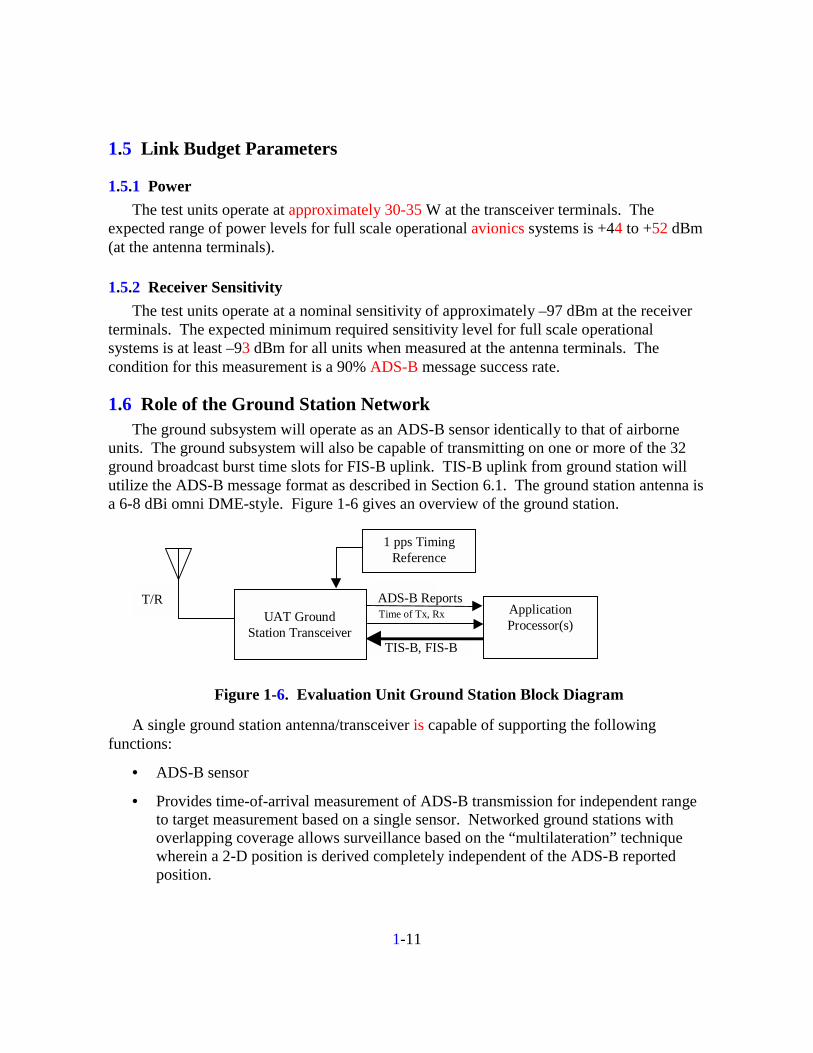
1.6 Role of the Ground Station Network The ground subsystem will operate as an ADS-B sensor identically to that of airborne
units. The ground subsystem will also be capable of transmitting on one or more of the 32 ground broadcast burst time slots for FIS-B uplink. TIS-B uplink from ground station will utilize the ADS-B message format as described in Section 6.1. The ground station antenna is a 6-8 dBi omni DME-style. Figure 1-6 gives an overview of the ground station.
T/R
TIS-B, FIS-B
ADS-B ReportsUAT Ground
Station Transceiver
ApplicationProcessor(s)
1 pps TimingReference
Time of Tx, Rx
Figure 1-6. Evaluation Unit Ground Station Block Diagram
A single ground station antenna/transceiver is capable of supporting the following functions:
• ADS-B sensor
• Provides time-of-arrival measurement of ADS-B transmission for independent range to target measurement based on a single sensor. Networked ground stations with overlapping coverage allows surveillance based on the “multilateration” technique wherein a 2-D position is derived completely independent of the ADS-B reported position.

1-12
• TIS-B uplink
• FIS-B uplink
• Provides timing beacon to airborne users that can serve as backup timing (see Section 1.1.3.2).
2-1
Section 2
System Overview
2.1 CNS Architecture
2.1.1 Intended Surveillance Role The UAT message structure, net access scheme, and signal structure were designed to
support all applications listed in DO-242. A range of UAT implementations are expected that would meet requirements of users in categories A0 through A3 as described in Section 5.3.
2.1.2 Quality of Service
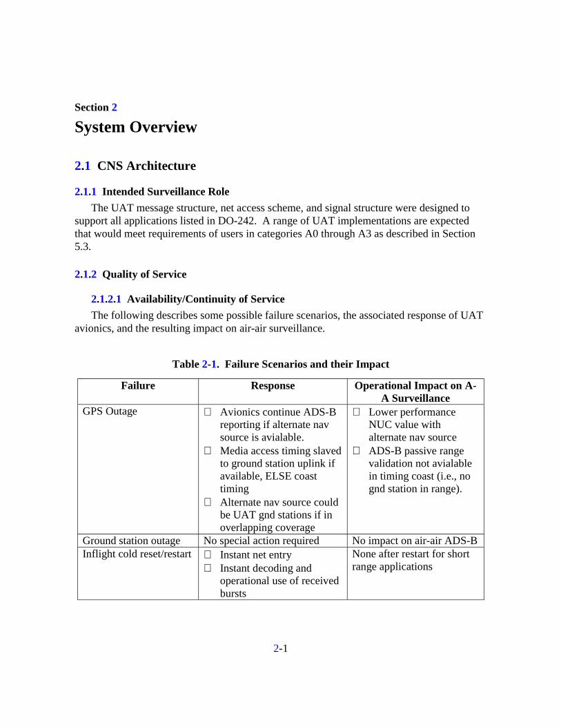
2.1.2.1 Availability/Continuity of Service The following describes some possible failure scenarios, the associated response of UAT
avionics, and the resulting impact on air-air surveillance.
Table 2-1. Failure Scenarios and their Impact
Failure Response Operational Impact on A-A Surveillance
GPS Outage ⇒ Avionics continue ADS-B reporting if alternate nav source is avialable.
⇒ Media access timing slaved to ground station uplink if available, ELSE coast timing
⇒ Alternate nav source could be UAT gnd stations if in overlapping coverage
⇒ Lower performance NUC value with alternate nav source
⇒ ADS-B passive range validation not avialable in timing coast (i.e., no gnd station in range).
Ground station outage No special action required No impact on air-air ADS-B Inflight cold reset/restart ⇒ Instant net entry
⇒ Instant decoding and operational use of received bursts
None after restart for short range applications

2-2
2.1.2.2 Integrity
2.1.2.2.1 Report Validation ADS-B message transmissions always start at one of 4000 Message Start Opportunities
(MSO) in every 1 second UAT frame. Every frame an MSO is selected on a pseudorandom basis such that no two aircraft will repeatedly select the same MSO. The Type 0 Extended ADS-B message contains a 12 bit field that encodes the MSO in which that transmission began. A receiver can—by knowing the MSO of the transmission and the time of receipt—calculate the propagation time of the message and hence range to target. This time can be used by airborne receiving systems or applications to perform a validation check of the range to the target as encoded in the ADS-B positional information. Ground stations can perform a similar function to validate range to a single station, or if at least three stations are in range of a given target, actual validation of the reported position can be performed using differential-time-of-arrival techniques. It is estimated that a receiver can reasonably measure time of arrival with accuracy better than 0.5 of a symbol period (500 ns). Evaluation units will support collection of data that can be used to determine this accuracy.
2.1.2.2.2 Probability of Undetected Message Error UAT employs a Reed Solomon (RS) FEC with 48 bits of FEC redundancy on ADS-B
messages. This level of RS FEC provides approximately 1.6x10⁻³ worst case probability of undetected error for any ADS-B burst. Additionally, the 24 bit CRC reduces this further by another 2-24 or 5.96x10⁻⁸. Therefore the worst case overall undetected error probability for an ADS-B message is 3.7x10⁻¹¹.
2.2 Transition Approach Aircraft under TCAS mandate will carry UAT alongside TCAS. UAT will augment
TCAS and the display of traffic to enable enhanced visual procedures not supported by TCAS alone. Early equipage will coincide with specific fleet operations requirements. Later, equipage will be affected by evolving capacity and safety enhancements such as paired approach, station keeping and surface surveillance. Finally, UAT systems will form the basis for future collision avoidance, utilizing the passive ranging capability in conjunction with ADS-B.
Non-TCAS aircraft will carry UAT alongside the existing transponder through the transition period. The first to equip will receive traffic in the cockpit (TIS-B) as well as graphical weather. Later UAT will serve an increasing role in navigation and surveillance. Figure 2-1 shows the transition timeline.

2-3
via
TIS-
Bup
linkInterim A-A
surveillance
Bdcst svcs groundinfrastructurecomplete. UAToffers nav backupin medium endhigh density airspace
VOR/DME avionicsbegin to be displaced
Early fleetepuipage (e.g.,Alaska, GOMEX,aircarrier huboperators)
Other aircraft(e.g., General
Aviation)
2000 2005 2010 2015
Air Carrieraircraft with
collision avoidance(C/A) mandate
SF-21 results in NAS-wide, ground stationdeployment. TIS-B,FIS-B svcs begin to beavailable
SSR transpondersdisplaced, ADS-B required in designatedairspace
via
TCAS
txpd
rin
terro
gatio
n
UATEquipage
UAT Equipage
Final A-A surveillance
C/A based on active interrogations augmented by UAT-based ADS-B(hybrid surveillance)
C/A based on passiveUAT ranging and ADS-B
via
UAT
A-A
Figure 2-1. UAT Transition and Role in CNS Architecture
3-1
Section 3
Information Exchange Functionality
3.1 Broadcast Message Generation
3.1.1 Information Source Interface and Information Compression Under normal conditions it is expected that the UAT would interface with a GPS sensor
and baro altitude source for any minimal installation. The GPS sensor would provide the position and velocity information as well as timing for ADS-B transmissions. No compression is used in encoding ADS-B information. Timing requirements are limited to a 1 pulse per second signal.
3.1.2 Message Assembly, State Vector Extrapolation, and Broadcast In evaluation units, position information is extrapolated to provide a 2 hz update rate to
the transmitter. This results in a time of applicability no greater than 500 ms from time of reception. Complete state vectors are contained in every transmission. Transmission rate is 1 hz average.
In end state units, position data in ADS-B messages will have a time of applicability based on the UTC second just prior to the transmission.
3.1.3 User Adaption Features Anonymity Upon initialization of UAT, a user who wishes not to broadcast their ICAO address can
set the “anonymity bit.” This replaces the 24 bit assigned address with one generated pseudorandomly at time of initialization. The anonymity bit is provided in the test units, however all CAA/Ohio Valley tests are expected to use discrete addresses.
3.2 Message Reception and Output Reports Refer to Table 1-2.
3.3 Reports and Supported Applications
3.3.1 Output Format wrt MASPS Format Since all dynamic state vector elements are contained in every UAT message, UAT
message payload is forwarded to applications without the need for decompression, ambiguity resolution or message assembly.

3-2
3.3.2 Application Interface Since all dynamic state vector elements are contained in every UAT message, UAT
message payload is forwarded to applications without the need for decompression, ambiguity resolution or message assembly.
4-1
Section 4
Message Reception and Co-Channel Interference
4.1 Interference Sources
4.1.1 TDMA Slot Overlap (Ground Uplink Transmissions) The segment of the UAT frame used for ground uplink operates as a slotted TDMA
access. Proximate ground stations would be assigned different time slots in order that cochannel interference is controlled.
4.1.2 Random Access Interference (ADS-B Transmissions) As described in section 1.1.1, ADS-B transmissions occur at a pseudorandomly
determined time based on one of 4000 Message Start Opportunities (MSO). Since time spacing between MSOs is less than the duration of an ADS-B message (plus guard time), the system behaves essentially as an unslotted random access. Since UAT is based on a clear channel concept, the system is limited primarily by system self-interference.
4.1.3 Ownship Supression Effects on Link Availability No ownship supression circuitry is used either to or from the UAT system on the test
aircraft. The need for this in the end state may depend on the other equipment on the aircraft and the end state frequency assigned for UAT.
4.2 Decoder Response
4.2.1 Synch Detection and False Synch Lockout Time UAT test units perform a sync lockout upon detection of the sync preamble. This is to
avoid detection of the occurrence of the sync sequence in the data. UAT end state units are expected to be able to operate with a preamble retrigger capability in parallel with processing of the previous overlapped message.
5-1
Section 5
Subsystem Block Diagrams
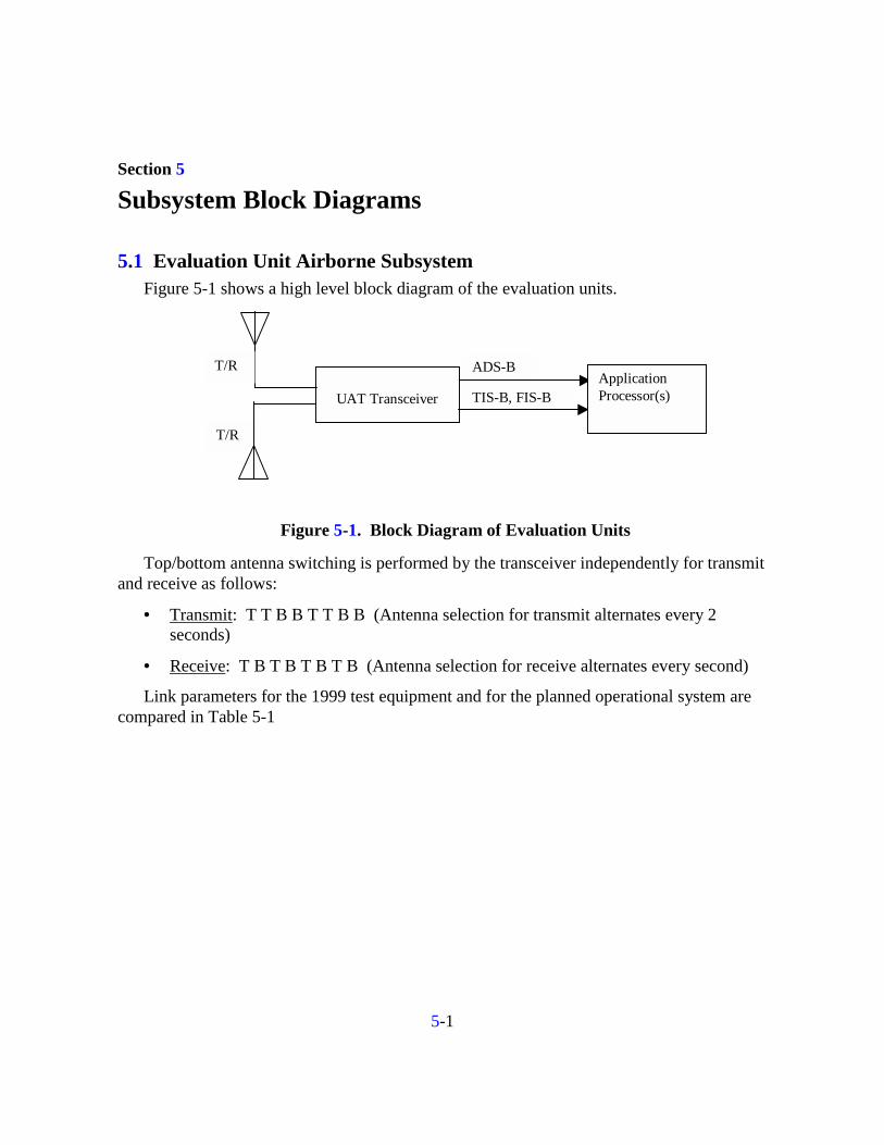
5.1 Evaluation Unit Airborne Subsystem Figure 5-1 shows a high level block diagram of the evaluation units.
T/R
T/R
TIS-B, FIS-B
ADS-B
UAT TransceiverApplicationProcessor(s)
Figure 5-1. Block Diagram of Evaluation Units
Top/bottom antenna switching is performed by the transceiver independently for transmit and receive as follows:
• Transmit: T T B B T T B B (Antenna selection for transmit alternates every 2 seconds)
• Receive: T B T B T B T B (Antenna selection for receive alternates every second)
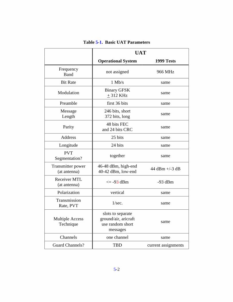
Link parameters for the 1999 test equipment and for the planned operational system are compared in Table 5-1
5-2
Table 5-1. Basic UAT Parameters
UAT
Operational System 1999 Tests
Frequency Band not assigned 966 MHz
Bit Rate 1 Mb/s same
Modulation Binary GFSK + 312 KHz same
Preamble first 36 bits same
Message Length
246 bits, short 372 bits, long same
Parity 48 bits FEC and 24 bits CRC same
Address 25 bits same
Longitude 24 bits same
PVT Segmentation? together same
Transmitter power (at antenna)
46-48 dBm, high-end 40-42 dBm, low-end 44 dBm +/-3 dB
Receiver MTL (at antenna) <= -93 dBm -93 dBm
Polarization vertical same
Transmission Rate, PVT 1/sec. same
Multiple Access Technique
slots to separate ground/air, aricraft use random short
messages
same
Channels one channel same
Guard Channels? TBD current assignments
5-3
5.1.1 Message Generation and Input Interface See Section 3.1.
5.1.2 Message Exchange Function (Link Budget and Assumptions)
5.1.2.1 Tx/Rx Antennas Evaluation units on CAA aircraft are implemented as a single transceiver that switches
automatically between top and bottom mounted antenna as described in Section 5.1. Antennas are quarter wave blade style and are cut to 966 MHz.
Given the 4 second message epoch proposed for operational units, some change is required to the transmission sequence to ensure a proper mix of message types for antenna switching. The following applies to operational units.
From Table 1-1 for operation units we have
a) Type 0 Extended (SV + call sign etc)
b) Type 1 Extended (SV + both TCPs)
c) Type 2 Extended (SV + future TBD payload)
For purposes of antenna switching we have an 8 second transmission cycle with the following repeating pattern:
a), b), b), c), c), b), b), a), ...repeat...
As with the evaluation systems, transmit antennas are alternating every two seconds (T, T, B, B, T, T, B, B, ...). Where applicable, the receive antenna switching pattern is T,B,T,B,T...
5.1.2.2 Receiver/Decoder MTL response curve to be provided by APL characterization. Evaluation units will be
able to perform overlap decoding in the case of a weaker message that overlaps a previous stronger message. A preamble retrigger function not included in the evaluation units will be required to support overlap processing when a stronger signal follows a weaker one.
5.1.3 Report Assembly Function and Output Interface See Section 1.3.1 and 1.3.2.

5-4
5.1.4 Relationship with Other Ownship Subsystems UAT is new equipment that is independent of any existing equipment on the aircraft
other than for ownship sensor inputs. No coordination with other equipment is used (e.g., for mutual supression).
5.2 Evaluation Unit Ground Subsystem The ground subsystem used in the evaluation, and described in Section 1.6, is consistent
with that proposed for the operational system.
5.3 Proposed Equipage Classes The table below shows the proposed equipage classes for the UAT. Only 2 distinct
classes are shown for UAT avionics installations. It is forseen for example that the MASPS A2/A3 distinction would be limited to onboard applications rather than UAT itself. In addition to the evaluation unit configuration shown in Section 5.1, the configurations shown below are also possible:
UAT Installed Equipment Classes for Mobile Use
Antenna Diversity Application DO-242 Equivalent Equipage
Class
Transmit Power Required3 Tx Rx
B1 Medium (<15,000’ max altitude)
High (>15,000’max altitude)
Alternates N/A Basic Surveillance
(Tx only)
B2 Low No N/A
3 Minimum transmitter power requirements are driven by A/G surveillance needs for Class B and A1
and by air-air needs for Class A2:
-Low !+37 dBm (5W)
-Medium! +44 dBm (25W)
-High! +50 dBm (100W)
(all as measured at the antenna terminals, tolerance is minus 0 and plus 2 dBm)
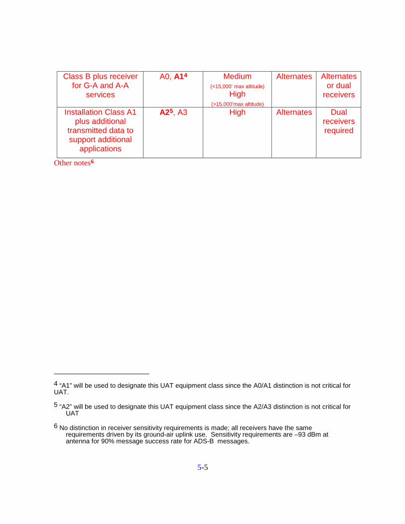
5-5
Class B plus receiver for G-A and A-A
services
A0, A14 Medium (<15,000’ max altitude)
High (>15,000’max altitude)
Alternates Alternates or dual
receivers
Installation Class A1 plus additional
transmitted data to support additional
applications
A25, A3 High Alternates Dual receivers required
Other notes6
4 “A1” will be used to designate this UAT equipment class since the A0/A1 distinction is not critical for UAT.
5 “A2” will be used to designate this UAT equipment class since the A2/A3 distinction is not critical for UAT
6 No distinction in receiver sensitivity requirements is made; all receivers have the same requirements driven by its ground-air uplink use. Sensitivity requirements are –93 dBm at antenna for 90% message success rate for ADS-B messages.
6-1
Section 6
Other Situational Awareness Services
6.1 TIS-B Description TIS-B will be supported in the UAT with a shared bandwidth concept with the ADS-B
channel resources. This is logical since the concept for TIS-B is that TIS-B reports are to be made only for non-ADS-B aircraft. Therefore as more aircraft become equipped with ADS-B the need for channel resources for TIS-B decline.
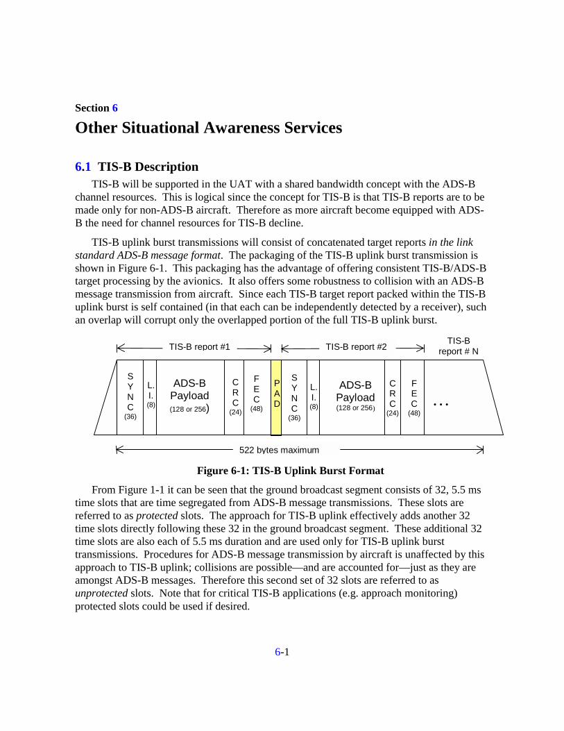
TIS-B uplink burst transmissions will consist of concatenated target reports in the link standard ADS-B message format. The packaging of the TIS-B uplink burst transmission is shown in Figure 6-1. This packaging has the advantage of offering consistent TIS-B/ADS-B target processing by the avionics. It also offers some robustness to collision with an ADS-B message transmission from aircraft. Since each TIS-B target report packed within the TIS-B uplink burst is self contained (in that each can be independently detected by a receiver), such an overlap will corrupt only the overlapped portion of the full TIS-B uplink burst.
L.I.(8)
SYNC
(36)
ADS-BPayload(128 or 256)
CRC
(24)
FEC
(48)
SYNC
(36)
L.I.(8)
ADS-BPayload(128 or 256)
CRC
(24)
FEC
(48)…
522 bytes maximum
TIS-B report #1 TIS-B report #2 TIS-Breport # N
PAD
Figure 6-1: TIS-B Uplink Burst Format
From Figure 1-1 it can be seen that the ground broadcast segment consists of 32, 5.5 ms time slots that are time segregated from ADS-B message transmissions. These slots are referred to as protected slots. The approach for TIS-B uplink effectively adds another 32 time slots directly following these 32 in the ground broadcast segment. These additional 32 time slots are also each of 5.5 ms duration and are used only for TIS-B uplink burst transmissions. Procedures for ADS-B message transmission by aircraft is unaffected by this approach to TIS-B uplink; collisions are possible—and are accounted for—just as they are amongst ADS-B messages. Therefore this second set of 32 slots are referred to as unprotected slots. Note that for critical TIS-B applications (e.g. approach monitoring) protected slots could be used if desired.

6-2
Figure 6-2 shows the overall media access concept including TIS-B.
1 Second UAT Frame(1 Mbps)
32 contiguous 5.5ms time slots
Channel resource for ground FIS-B transmissions (protected slots)
64 contiguous 5.5 ms time slots Channel resource for ground TIS-B transmissions
Channel resource for airborne ADS-B transmissions812 ms unslotted random access
32 contiguous 5.5ms time slots Unprotected slots used only for TIS-B uplinks as
needed
Figure 6-2: Overall Media Access Plan with TIS-B
6.2 FIS-B Description FIS-B is supported with protected time slots in the ground broadcast segment of the UAT
frame. The total bandwidth available to each ground station can be estimated using some simplifying assumptions:
• All ground stations operate in a regular cellular pattern with intersite spacing of approximately 100 nmi.
• The UAT waveform’s tolerance to cochannel interference will dictate the cellular reuse pattern that can be achieved as follows if free space path loss is assumed for the desired and undesired signals:
− 4 cell pattern ~1:2.5 desired to undesired (D/U)distance ratio (8 dB)
− 7 cell pattern ~1:3.6 D/U distance ratio (11 dB)
− 12 cell pattern ~1:5 D/U distance ratio (14 dB)
− 19 cell pattern ~1:6.5 D/U distance ratio (16 dB)
• Assume the UAT waveform gives at least 90% message success rate at 6 dB D/U based on bench measurement.
• If 5 dB margin for fading is assumed, this allows operation with 7 cell pattern.

6-3
Therefore if bandwidth is distributed evenly between the sites, each site could operate with 4 time slots at ~3.7 kbps payload per slot for a total bit rate of about 15 kbps per site.
7-1
Section 7
Growth Potential and Other Features
7.1 Capacity for Extra ADS-B Payloads and Applications From Table 1-1 it can be seen that there are two message types defined that in addition to
conveying the complete state vector, also have about 90 additional bits of payload that is undefined and could be used for reporting data not included in DO-242. Examples of such data would be additional TCPs or weather data from pilot entered data or on-board automated sensors.
7.2 Backup Navigation From Ground Stations Evaluation units will be capable of transmitting and recording the information necessary
to assess the backup navigation performance as supported by the UAT waveform. This capability is related to that discussed in Section 2.1.2.2.1 used for range validation of ADS-B reports.
7.3 Recent Eurocontrol Requirements These recent requirements represent additional payload that must be conveyed in UAT messages to support A-G and A-A applications envisioned by Eurocontrol. Specifically, extra data items that must be accomodated are:
• 2 additional TCPs
• selected altitude
• heading
The following is proposed as a way of accomodating this information for purpose of performance evaluation (see Table 1-1 for operational system):
⇒ Selected altitude and heading are accomodated in the “Spare or Other” category from the Type0 Extended Message. Collectively, these bits are allocated as follows:
" 9 heading
" 10 selected altitude
" 12 transmission time (MSO)
" 2 spare
This allows this information to be transmitted once every 4 seconds.

7-2
⇒ Two additional TCPs are accomodated in the 130 bits denoted for future definition in the Table in the Type2 Extended Message. Encoding would be consistent with that of the original 2 TCPs. Note that these 2 new TCPs would be transmitted at only one half the rate of the original two. To balance performance it might be appropriate to ensure the “furthest downstream” waypoints have the full 0.5 hz transmission rate.7
7 For air-air it would seem of little use to broadcast TCPs for much beyond one half the ADS-B link reception
range or approximately 75 nmi. Given this, the furthest two TCPs should always get priority and be conveyed at high rate (0.5 hz) vs the closest two that would be conveyed at the lower rate (0.25 hz). Sufficient bits have been allocated to ensure that all TCPs can be encoded independently and numbered.

1