System Controls - Amazon S3...Controls 2 Energy Savings Although VRF technology inherently results...
24
System Controls PRODUCT CATALOG
Transcript of System Controls - Amazon S3...Controls 2 Energy Savings Although VRF technology inherently results...
System Controls
PRODUCT CATALOG
Controls
2
Energy SavingsAlthough VRF technology inherently results in an extremely efficient system, there are several ways in which controls can help save even more energy:
Scheduling and occupancy detection – Conditions the space only when necessary.
Setpoint range limit – Prevents the setpoint from being set to extremes that can result in overcooling or overheating of the space.
Remote controller lock – Prevents users from changing indoor unit operation.
Temperature limit – Allows indoor units to be shut off during unoccupied periods with an override feature to keep interior temperatures from reaching extremes.
Time limit (unoccupied override) – Permits a unit to be turned on during unoccupied times and automatically shut down after a specified amount of run time.
Convenience Auto-changeover – Automatically switches the indoor unit into the correct mode to optimize space comfort.
Central control – Allows distributed control from one location.
Web access – Allows distributed control from a remote location.
Visual and e-mail alarm notification – Immediately indicates when a system is not operating at optimal conditions.
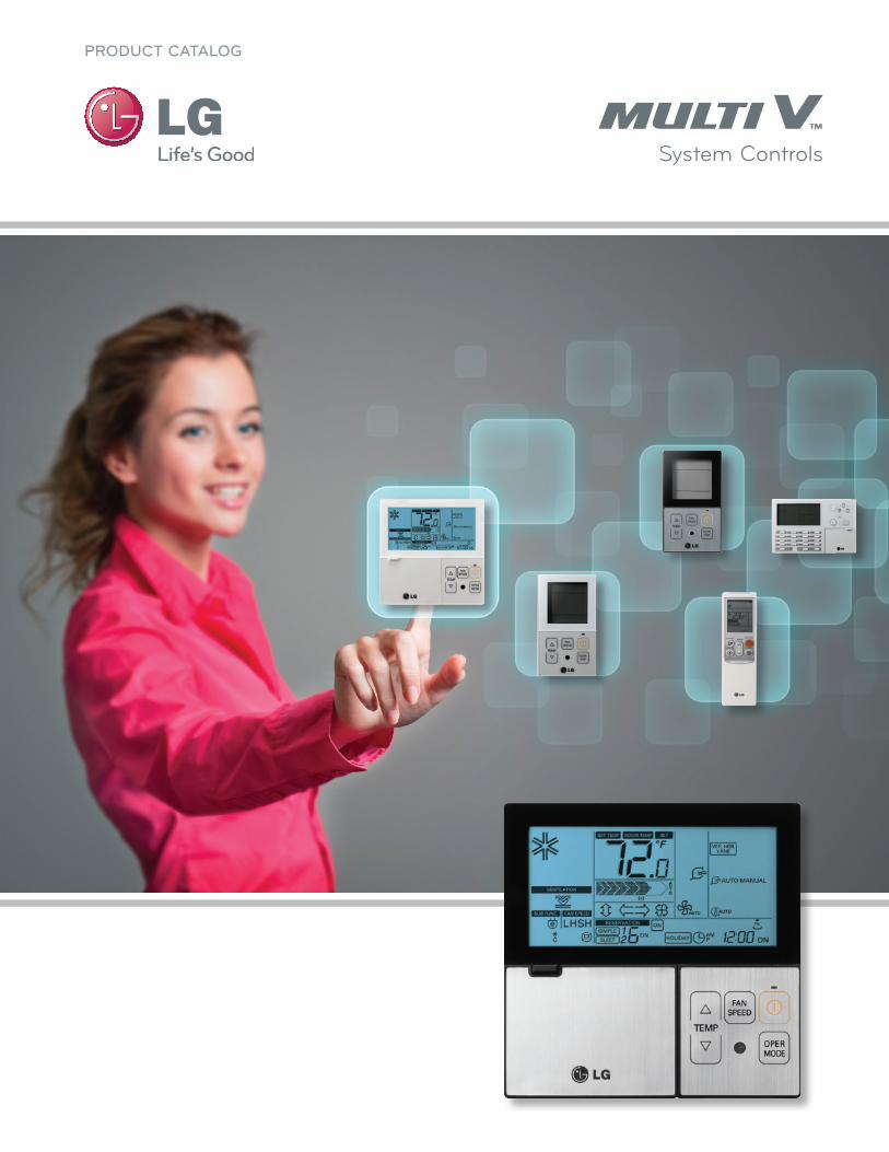
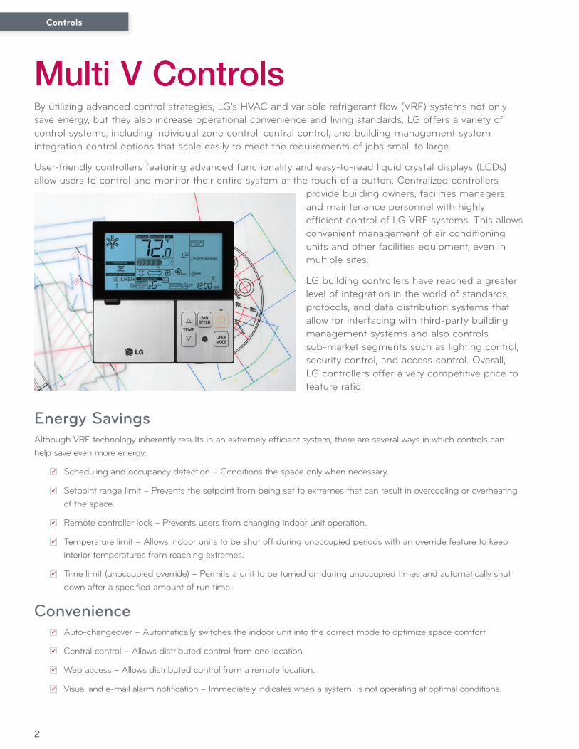
Multi V ControlsBy utilizing advanced control strategies, LG’s HVAC and variable refrigerant flow (VRF) systems not only save energy, but they also increase operational convenience and living standards. LG offers a variety of control systems, including individual zone control, central control, and building management system integration control options that scale easily to meet the requirements of jobs small to large.
User-friendly controllers featuring advanced functionality and easy-to-read liquid crystal displays (LCDs) allow users to control and monitor their entire system at the touch of a button. Centralized controllers
provide building owners, facilities managers, and maintenance personnel with highly efficient control of LG VRF systems. This allows convenient management of air conditioning units and other facilities equipment, even in multiple sites.
LG building controllers have reached a greater level of integration in the world of standards, protocols, and data distribution systems that allow for interfacing with third-party building management systems and also controls sub-market segments such as lighting control, security control, and access control. Overall, LG controllers offer a very competitive price to feature ratio.
Controls
3
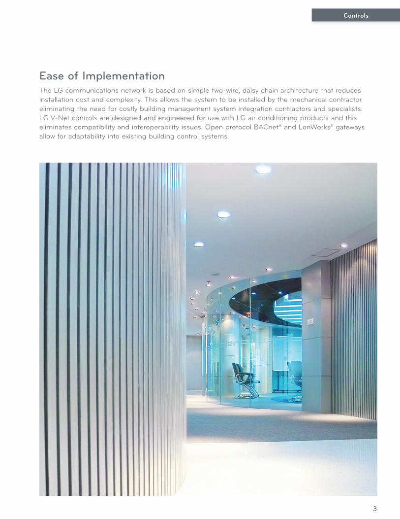
Ease of ImplementationThe LG communications network is based on simple two-wire, daisy chain architecture that reduces installation cost and complexity. This allows the system to be installed by the mechanical contractor eliminating the need for costly building management system integration contractors and specialists. LG V-Net controls are designed and engineered for use with LG air conditioning products and this eliminates compatibility and interoperability issues. Open protocol BACnet® and LonWorks® gateways allow for adaptability into existing building control systems.
4
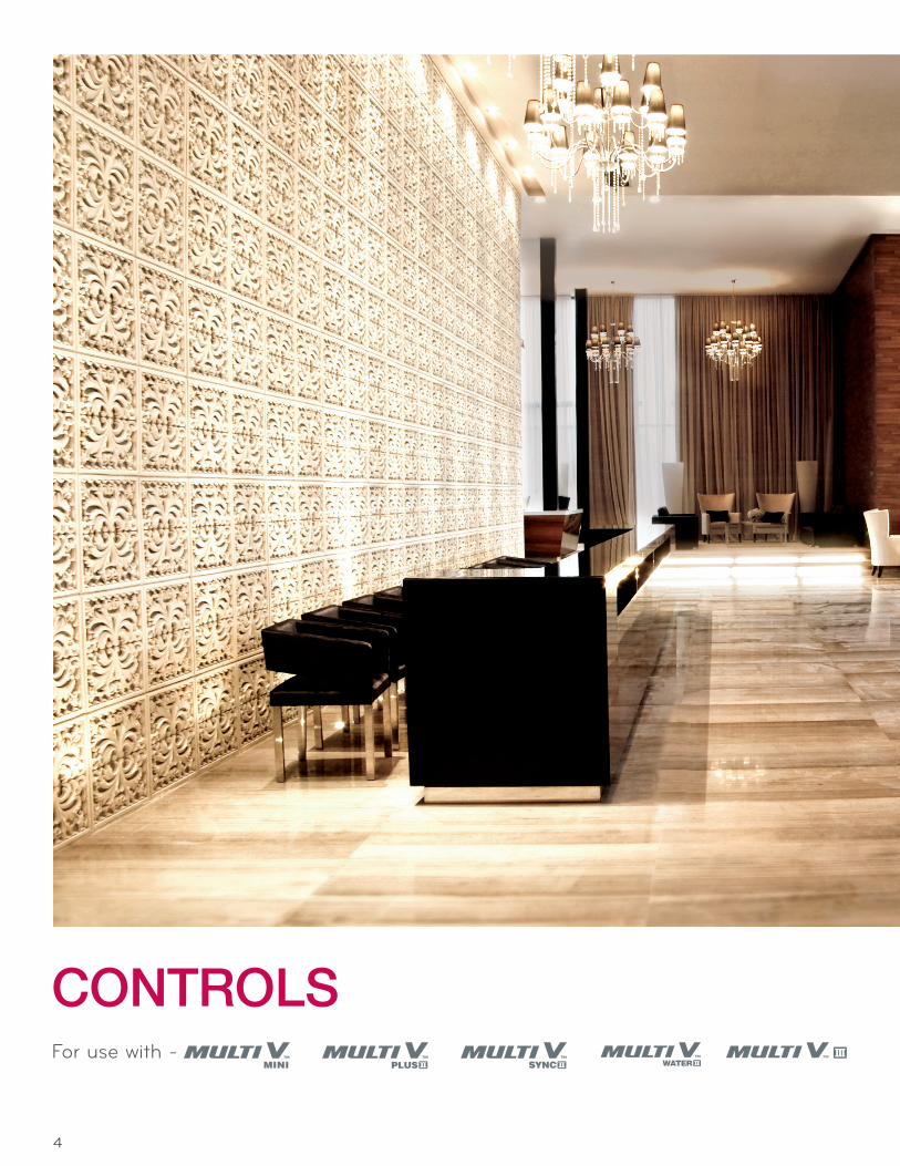
CONTROLSFor use with -
5
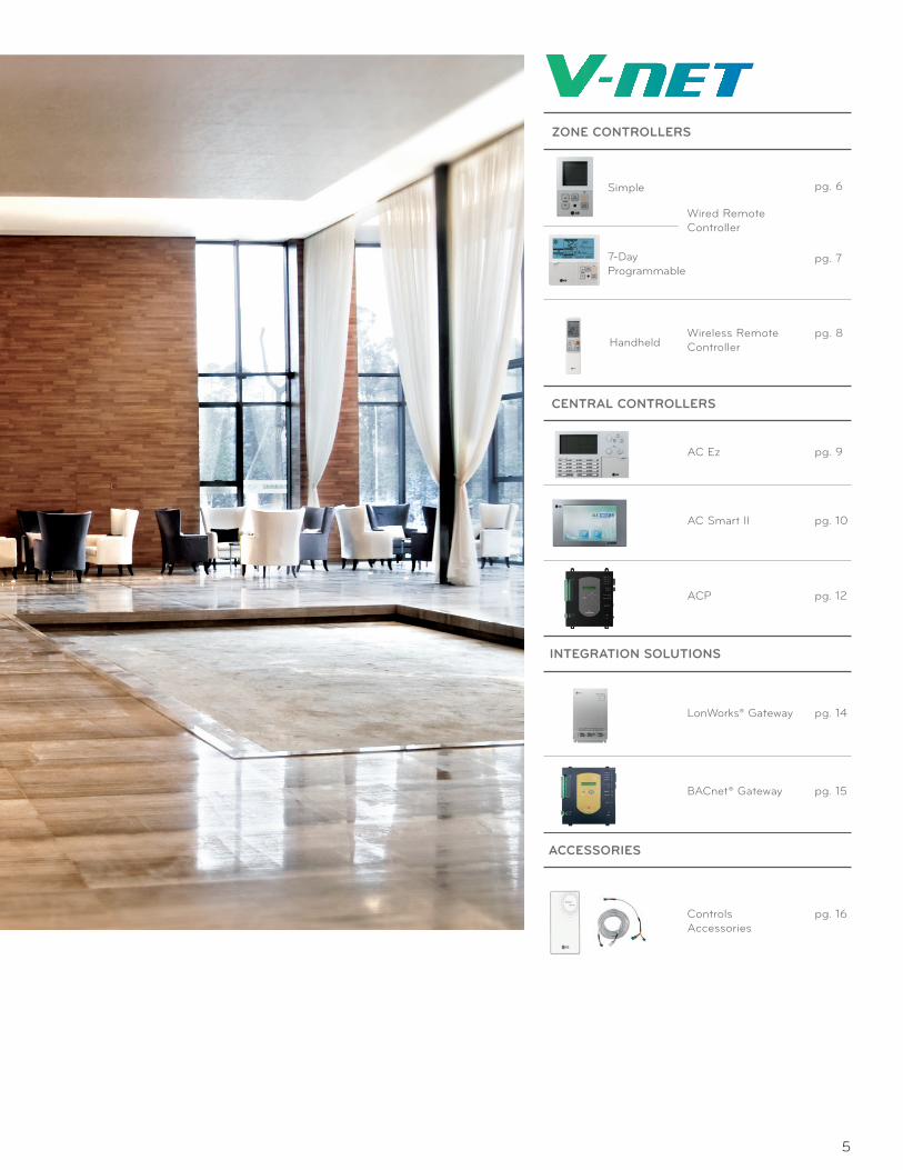
ZONE CONTROLLERS
CENTRAL CONTROLLERS
Wireless RemoteController
Wired RemoteController
AC Ez
Simple
7-DayProgrammable
INTEGRATION SOLUTIONS
Handheld
pg. 6
pg. 7
pg. 9
ACP pg. 12
Gateway
BACnet®
LonWorks®
Gateway
pg. 14
pg. 15
pg. 10AC Smart II
pg. 8
ACCESSORIES
Controls Accessories
pg. 16
Controls
6
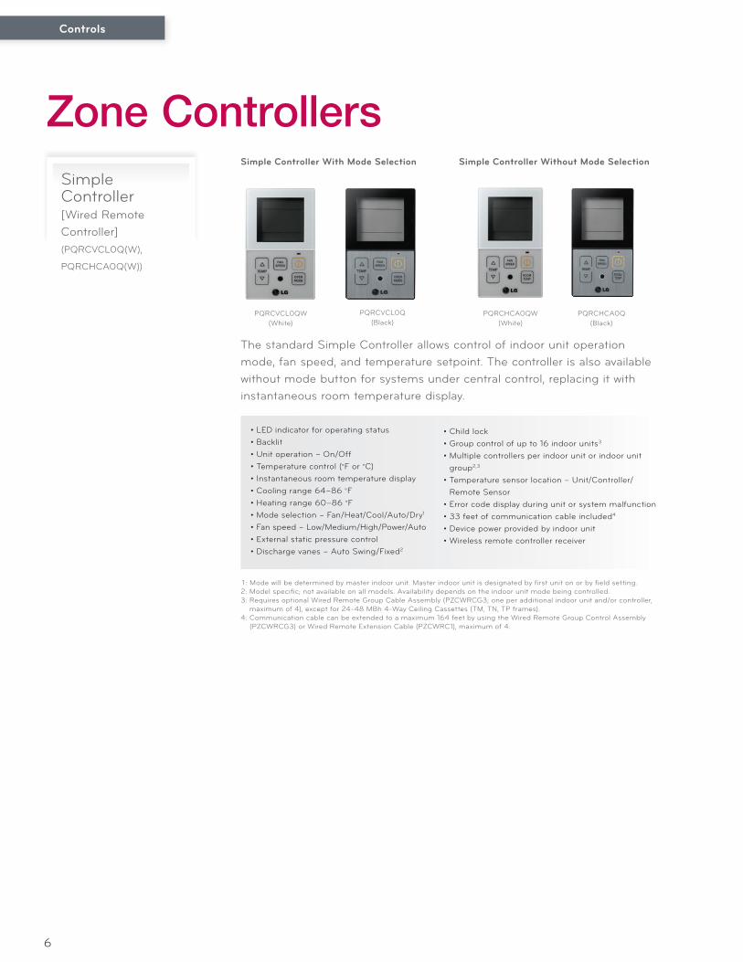
• LED indicator for operating status• Backlit• Unit operation – On/Off• Temperature control (°F or °C)• Instantaneous room temperature display• Cooling range 64–86 °F • Heating range 60–86 °F • Mode selection – Fan/Heat/Cool/Auto/Dry1
• Fan speed – Low/Medium/High/Power/Auto• External static pressure control• Discharge vanes – Auto Swing/Fixed2
1 : Mode will be determined by master indoor unit. Master indoor unit is designated by first unit on or by field setting. 2: Model specific; not available on all models. Availability depends on the indoor unit mode being controlled.3: Requires optional Wired Remote Group Cable Assembly (PZCWRCG3; one per additional indoor unit and/or controller,
maximum of 4), except for 24-48 MBh 4-Way Ceiling Cassettes (TM, TN, TP frames).4: Communication cable can be extended to a maximum 164 feet by using the Wired Remote Group Control Assembly
(PZCWRCG3) or Wired Remote Extension Cable (PZCWRC1), maximum of 4.
Simple Controller[Wired Remote Controller](PQRCVCL0Q(W),
PQRCHCA0Q(W))
The standard Simple Controller allows control of indoor unit operation mode, fan speed, and temperature setpoint. The controller is also available without mode button for systems under central control, replacing it with instantaneous room temperature display.
• Child lock• Group control of up to 16 indoor units3
• Multiple controllers per indoor unit or indoor unit group2,3
• Temperature sensor location – Unit/Controller/ Remote Sensor
• Error code display during unit or system malfunction• 33 feet of communication cable included4
• Device power provided by indoor unit• Wireless remote controller receiver
Zone Controllers
PQRCVCL0QW (White)
PQRCVCL0Q(Black)
Simple Controller With Mode Selection Simple Controller Without Mode Selection
PQRCHCA0QW(White)
PQRCHCA0Q(Black)
Controls
7
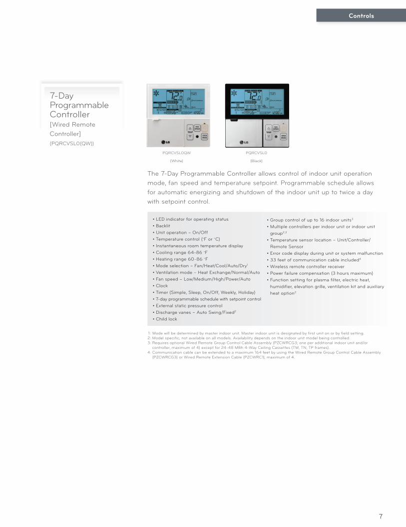
• LED indicator for operating status• Backlit• Unit operation – On/Off• Temperature control (°F or °C)• Instantaneous room temperature display• Cooling range 64-86 °F • Heating range 60-86 °F • Mode selection – Fan/Heat/Cool/Auto/Dry1
• Ventilation mode – Heat Exchange/Normal/Auto• Fan speed – Low/Medium/High/Power/Auto• Clock• Timer (Simple, Sleep, On/Off, Weekly, Holiday)• 7-day programmable schedule with setpoint control• External static pressure control• Discharge vanes – Auto Swing/Fixed2
• Child lock
1 : Mode will be determined by master indoor unit. Master indoor unit is designated by first unit on or by field setting. 2: Model specific; not available on all models. Availability depends on the indoor unit model being controlled.3: Requires optional Wired Remote Group Control Cable Assembly (PZCWRCG3; one per additional indoor unit and/or
controller, maximum of 4) except for 24-48 MBh 4-Way Ceiling Cassettes (TM, TN, TP frames).4: Communication cable can be extended to a maximum 164 feet by using the Wired Remote Group Control Cable Assembly
(PZCWRCG3) or Wired Remote Extension Cable (PZCWRC1), maximum of 4.
7-Day Programmable Controller[Wired Remote Controller](PQRCVSL0(QW))
The 7-Day Programmable Controller allows control of indoor unit operation mode, fan speed and temperature setpoint. Programmable schedule allows for automatic energizing and shutdown of the indoor unit up to twice a day with setpoint control.
• Group control of up to 16 indoor units3
• Multiple controllers per indoor unit or indoor unit group2,3
• Temperature sensor location – Unit/Controller/Remote Sensor
• Error code display during unit or system malfunction• 33 feet of communication cable included4
• Wireless remote controller receiver• Power failure compensation (3 hours maximum)• Function setting for plasma filter, electric heat,
humidifier, elevation grille, ventilation kit and auxiliary heat option2
PQRCVSL0QW
(White)
PQRCVSL0
(Black)
Controls
8
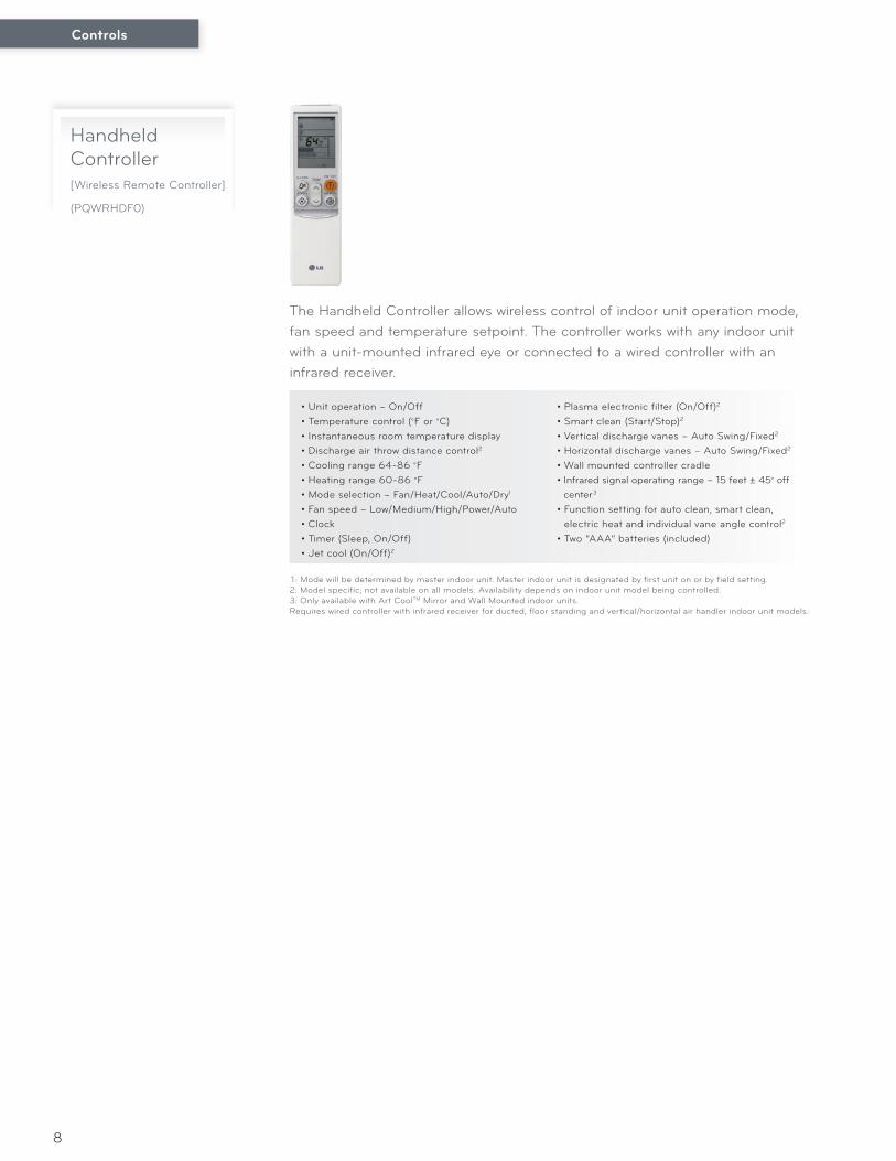
• Unit operation – On/Off• Temperature control (°F or °C)• Instantaneous room temperature display• Discharge air throw distance control2
• Cooling range 64-86 °F • Heating range 60-86 °F • Mode selection – Fan/Heat/Cool/Auto/Dry1
• Fan speed – Low/Medium/High/Power/Auto• Clock• Timer (Sleep, On/Off)• Jet cool (On/Off)2
1 : Mode will be determined by master indoor unit. Master indoor unit is designated by first unit on or by field setting.2: Model specific; not available on all models. Availability depends on indoor unit model being controlled.3: Only available with Art CoolTM Mirror and Wall Mounted indoor units.Requires wired controller with infrared receiver for ducted, floor standing and vertical/horizontal air handler indoor unit models.
Handheld Controller[Wireless Remote Controller]
(PQWRHDF0)
The Handheld Controller allows wireless control of indoor unit operation mode, fan speed and temperature setpoint. The controller works with any indoor unit with a unit-mounted infrared eye or connected to a wired controller with an infrared receiver.
• Plasma electronic filter (On/Off)2
• Smart clean (Start/Stop)2
• Vertical discharge vanes – Auto Swing/Fixed2
• Horizontal discharge vanes – Auto Swing/Fixed2
• Wall mounted controller cradle• Infrared signal operating range – 15 feet ± 45° off
center3
• Function setting for auto clean, smart clean, electric heat and individual vane angle control2
• Two “AAA” batteries (included)
Controls
9
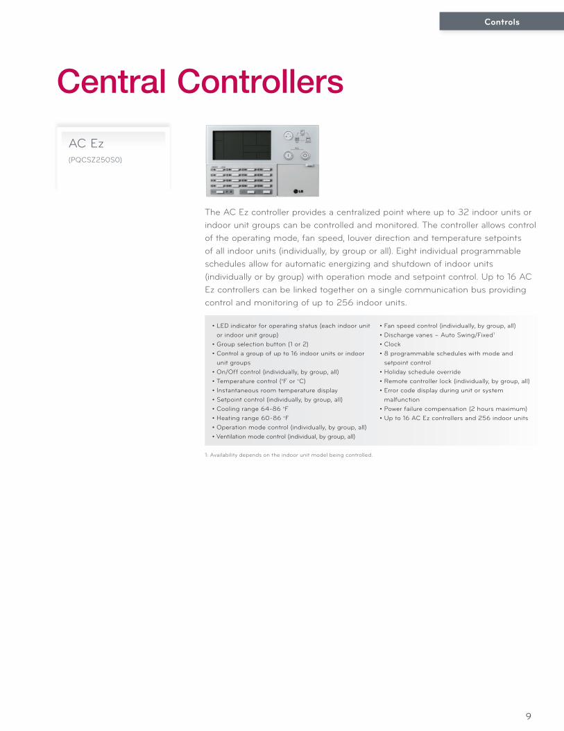
• LED indicator for operating status (each indoor unit or indoor unit group)
• Group selection button (1 or 2)• Control a group of up to 16 indoor units or indoor
unit groups• On/Off control (individually, by group, all)• Temperature control (°F or °C)• Instantaneous room temperature display• Setpoint control (individually, by group, all)• Cooling range 64-86 °F • Heating range 60-86 °F • Operation mode control (individually, by group, all)• Ventilation mode control (individual, by group, all)
1: Availability depends on the indoor unit model being controlled.
AC Ez(PQCSZ250S0)
• Fan speed control (individually, by group, all)• Discharge vanes – Auto Swing/Fixed1
• Clock• 8 programmable schedules with mode and
setpoint control• Holiday schedule override• Remote controller lock (individually, by group, all)• Error code display during unit or system
malfunction• Power failure compensation (2 hours maximum)• Up to 16 AC Ez controllers and 256 indoor units
The AC Ez controller provides a centralized point where up to 32 indoor units or indoor unit groups can be controlled and monitored. The controller allows control of the operating mode, fan speed, louver direction and temperature setpoints of all indoor units (individually, by group or all). Eight individual programmable schedules allow for automatic energizing and shutdown of indoor units (individually or by group) with operation mode and setpoint control. Up to 16 AC Ez controllers can be linked together on a single communication bus providing control and monitoring of up to 256 indoor units.
Central Controllers
Controls
10
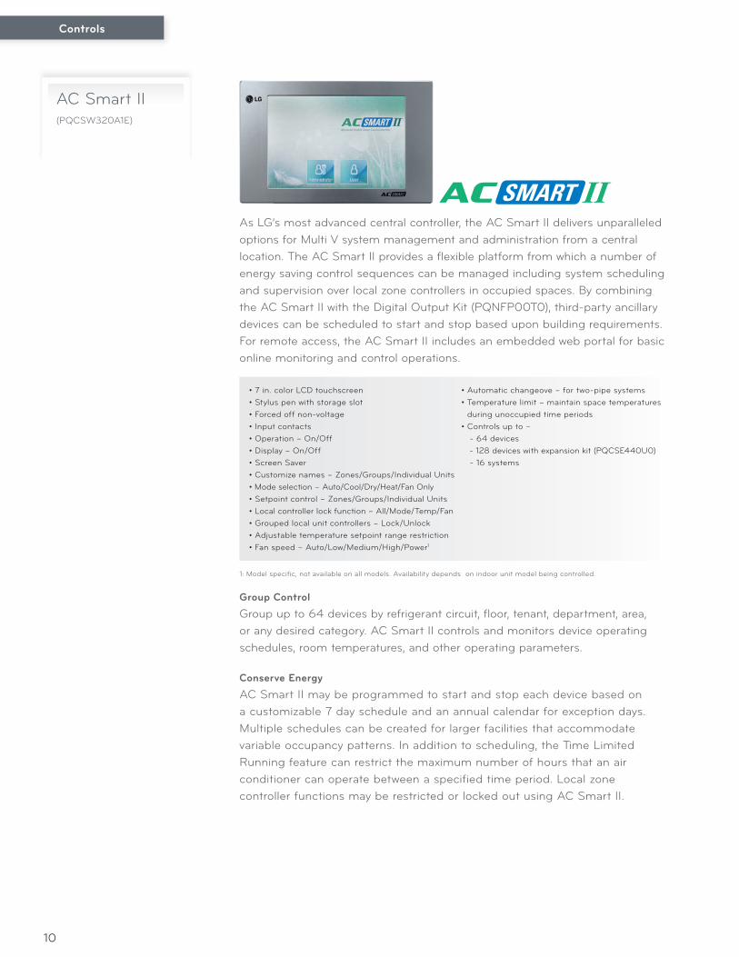
Group ControlGroup up to 64 devices by refrigerant circuit, floor, tenant, department, area, or any desired category. AC Smart II controls and monitors device operating schedules, room temperatures, and other operating parameters.
Conserve EnergyAC Smart II may be programmed to start and stop each device based on a customizable 7 day schedule and an annual calendar for exception days. Multiple schedules can be created for larger facilities that accommodate variable occupancy patterns. In addition to scheduling, the Time Limited Running feature can restrict the maximum number of hours that an air conditioner can operate between a specified time period. Local zone controller functions may be restricted or locked out using AC Smart II.
• 7 in. color LCD touchscreen• Stylus pen with storage slot• Forced off non-voltage• Input contacts• Operation – On/Off• Display – On/Off• Screen Saver• Customize names – Zones/Groups/Individual Units• Mode selection – Auto/Cool/Dry/Heat/Fan Only• Setpoint control – Zones/Groups/Individual Units• Local controller lock function – All/Mode/Temp/Fan• Grouped local unit controllers – Lock/Unlock• Adjustable temperature setpoint range restriction• Fan speed – Auto/Low/Medium/High/Power1
1: Model specific, not available on all models. Availability depends on indoor unit model being controlled.
AC Smart II(PQCSW320A1E)
As LG’s most advanced central controller, the AC Smart II delivers unparalleled options for Multi V system management and administration from a central location. The AC Smart II provides a flexible platform from which a number of energy saving control sequences can be managed including system scheduling and supervision over local zone controllers in occupied spaces. By combining the AC Smart II with the Digital Output Kit (PQNFP00T0), third-party ancillary devices can be scheduled to start and stop based upon building requirements. For remote access, the AC Smart II includes an embedded web portal for basic online monitoring and control operations.
• Automatic changeove – for two-pipe systems• Temperature limit – maintain space temperatures
during unoccupied time periods• Controls up to – - 64 devices - 128 devices with expansion kit (PQCSE440U0) - 16 systems
Controls
11
Tabbed Navigation• Basic Control• Schedule• History• Auto Control• System Setup
Indoor Unit Operating Status Display• Display Zones/Groups/Individual Units• Local controller Locked/Unlocked• Operating mode - Auto/Cool/Heat• Unit operation - On/Off/Malfunction• Discharge louver (swing) - On/Off1
Device Setpoint Data Display Status• Display device type - Indoor Unit/Ventilator/AWHP
(Air-to-Water Heat Pump)/On/Off Unit• Display device by Zones/Groups/Individual Units• Indoor unit average temperature set-point-Zones/
Groups
• Indoor unit average room temperature-Zones/Groups
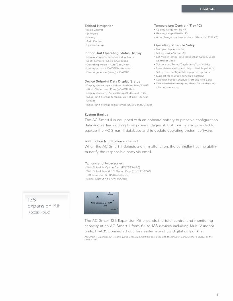
128 Expansion Kit(PQCSE440U0)
The AC Smart 128 Expansion Kit expands the total control and monitoring capacity of an AC Smart II from 64 to 128 devices including Multi V indoor units, PI-485 connected ductless systems and LG digital output kits.
System Backup
The AC Smart II is equipped with an onboard battery to preserve configuration data and settings during brief power outages. A USB port is also provided to backup the AC Smart II database and to update operating system software.
Malfunction Notification via E-mail
When the AC Smart II detects a unit malfunction, the controller has the ability to notify the responsible party via email.
AC Smart II Expansion Kit is not required when AC Smart II is combined with the BACnet® Gateway (PQNFB17B0) on the same V-Net.
Temperature Control (ºF or ºC)• Cooling range 64-86 (°F)• Heating range 60-86 (°F)• Auto changeover temperature differential 2-14 (°F)
Operating Schedule Setup• Multiple display modes• Set by Device/Group/All• Set Mode/Temp/Temp Range/Fan Speed/Local
Controller Lock• Set by Hour/Period/Day/Month/Year/Holiday• Event driven weekly and daily schedule patterns• Set by user configurable equipment groups• Support for multiple schedule patterns• Calendar-based schedule start and end dates• Calendar-based exception dates for holidays and
other observances
Options and Accessories• Web Schedule Option Card (PQCSE341A0)• Web Schedule and PDI Option Card (PQCSE342A0)• 128 Expansion Kit (PQCSE440U0)• Digital Output Kit (PQNFP00T0)
Controls
12
Group ControlGroup up to 64 devices by refrigerant circuit, floor, tenant, department, area, or any desired category. ACP controls and monitors device operating schedules, room temperatures, and other operating parameters.
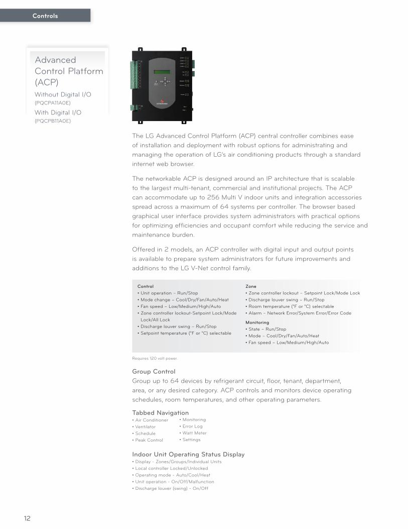
Advanced Control Platform (ACP)Without Digital I/O (PQCPA11A0E)
With Digital I/O (PQCPB11A0E)
The LG Advanced Control Platform (ACP) central controller combines ease of installation and deployment with robust options for administrating and managing the operation of LG’s air conditioning products through a standard internet web browser.
The networkable ACP is designed around an IP architecture that is scalable to the largest multi-tenant, commercial and institutional projects. The ACP can accommodate up to 256 Multi V indoor units and integration accessories spread across a maximum of 64 systems per controller. The browser based graphical user interface provides system administrators with practical options for optimizing efficiencies and occupant comfort while reducing the service and maintenance burden.
Offered in 2 models, an ACP controller with digital input and output points is available to prepare system administrators for future improvements and additions to the LG V-Net control family.
Control• Unit operation – Run/Stop• Mode change – Cool/Dry/Fan/Auto/Heat• Fan speed – Low/Medium/High/Auto• Zone controller lockout-Setpoint Lock/Mode
Lock/All Lock• Discharge louver swing – Run/Stop• Setpoint temperature (°F or °C) selectable
Zone• Zone controller lockout – Setpoint Lock/Mode Lock• Discharge louver swing – Run/Stop• Room temperature (°F or °C) selectable• Alarm – Network Error/System Error/Error Code
Monitoring• State – Run/Stop• Mode – Cool/Dry/Fan/Auto/Heat• Fan speed – Low/Medium/High/Auto
Tabbed Navigation• Air Conditioner• Ventilator• Schedule• Peak Control
Indoor Unit Operating Status Display• Display - Zones/Groups/Individual Units• Local controller Locked/Unlocked• Operating mode - Auto/Cool/Heat• Unit operation - On/Off/Malfunction• Discharge louver (swing) - On/Off
• Monitoring• Error Log• Watt Meter• Settings
Requires 120 volt power.
Controls
13
Device Setpoint Data Display Status• Display device type - Indoor Unit/Ventilator/AWHP (Air-to-Water Heat Pump)/On-Off Unit• Display device by Zones/Groups/Individual Units• Indoor unit average temperature setpoint - Zones/Groups• Indoor unit average room temperature - Zones/Groups
Temperature Control (ºF or ºC)• Cooling range: 64-86 °F• Heating range 60-86 °F
Conserve EnergyACP may be programmed to start and stop each device based on a customizable 7 day schedule and an annual calendar for exception days. Multiple schedules can be created for larger facilities that accommodate variable occupancy patterns. In addition to scheduling, the Peak Wattage function will limit peak energy usage by cycling indoor units in sequence limiting the number of air conditioning units on at any given time. Local zone controller functions may be locked out using the ACP.
Operating Schedule Setup• Set by Device/Group/All• Set Mode/Temp/Fan Speed/Local Controller Lock• Set by Hour/Period/Day/Month/Year/Holiday• Event driven weekly and daily schedule patterns• Set by user configurable equipment groups• Calendar-based schedule start and end dates
• Calendar-based exception dates for holidays and other observances
PDI (Power Distribution Indicator) When combined with PDI, the ACP allows calculated apportioned outdoor unit power consumption data to be viewed and saved over the web.
Options and Accessories• Digital Output Kit (PQNFP00T0)
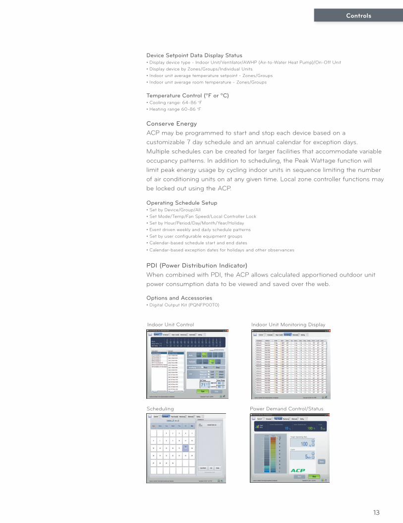
Indoor Unit Monitoring Display
Scheduling Power Demand Control/Status
Indoor Unit Control
Controls
14
Integration Solutions
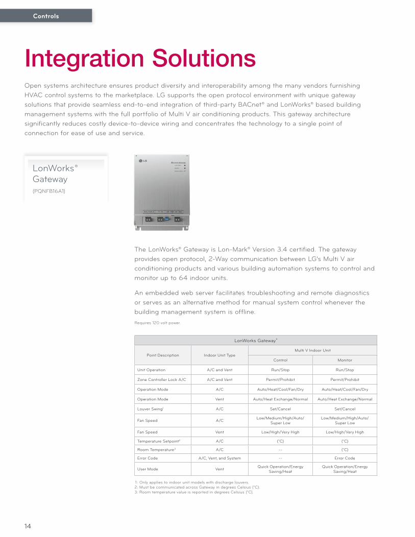
LonWorks® Gateway(PQNFB16A1)
The LonWorks® Gateway is Lon-Mark® Version 3.4 certified. The gateway provides open protocol, 2-Way communication between LG’s Multi V air conditioning products and various building automation systems to control and monitor up to 64 indoor units.
An embedded web server facilitates troubleshooting and remote diagnostics or serves as an alternative method for manual system control whenever the building management system is offline.
Open systems architecture ensures product diversity and interoperability among the many vendors furnishing HVAC control systems to the marketplace. LG supports the open protocol environment with unique gateway solutions that provide seamless end-to-end integration of third-party BACnet® and LonWorks® based building management systems with the full portfolio of Multi V air conditioning products. This gateway architecture significantly reduces costly device-to-device wiring and concentrates the technology to a single point of connection for ease of use and service.
1 : Only applies to indoor unit models with discharge louvers.2: Must be communicated across Gateway in degrees Celsius (°C).3: Room temperature value is reported in degrees Celsius (°C).
LonWorks Gateway®
Point Description Indoor Unit TypeMulti V Indoor Unit
Control Monitor
Unit Operation A/C and Vent Run/Stop Run/Stop
Zone Controller Lock A/C A/C and Vent Permit/Prohibit Permit/Prohibit
Operation Mode A/C Auto/Heat/Cool/Fan/Dry Auto/Heat/Cool/Fan/Dry
Operation Mode Vent Auto/Heat Exchange/Normal Auto/Heat Exchange/Normal
Louver Swing1 A/C Set/Cancel Set/Cancel
Fan Speed A/C Low/Medium/High/Auto/Super Low
Low/Medium/High/Auto/Super Low
Fan Speed Vent Low/High/Very High Low/High/Very High
Temperature Setpoint2 A/C (°C) (°C)
Room Temperature3 A/C -- (°C)
Error Code A/C, Vent, and System -- Error Code
User Mode Vent Quick Operation/Energy Saving/Heat
Quick Operation/Energy Saving/Heat
Requires 120 volt power.
Controls
15
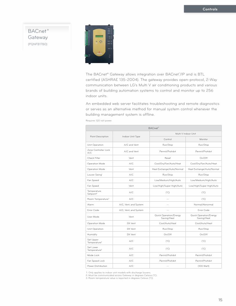
BACnet ® Gateway(PQNFB17B0)
The BACnet® Gateway allows integration over BACnet®/IP and is BTL certified (ASHRAE 135-2004). The gateway provides open-protocol, 2-Way communication between LG’s Multi V air conditioning products and various brands of building automation systems to control and monitor up to 256 indoor units.
An embedded web server facilitates troubleshooting and remote diagnostics or serves as an alternative method for manual system control whenever the building management system is offline.
BACnet®
Point Description Indoor Unit TypeMulti V Indoor Unit
Control Monitor
Unit Operation A/C and Vent Run/Stop Run/Stop
Zone Controller Lock A/C A/C and Vent Permit/Prohibit Permit/Prohibit
Check Filter Vent Reset On/Off
Operation Mode A/C Cool/Dry/Fan/Auto/Heat Cool/Dry/Fan/Auto/Heat
Operation Mode Vent Heat Exchange/Auto/Normal Heat Exchange/Auto/Normal
Louver Swing1 A/C Run/Stop Run/Stop
Fan Speed A/C Low/Medium/High/Auto Low/Medium/High/Auto
Fan Speed Vent Low/High/Super High/Auto Low/High/Super High/Auto
Temperature Setpoint2 A/C (°C) (°C)
Room Temperature3 A/C -- (°C)
Alarm A/C, Vent, and System -- Normal/Abnormal
Error Code A/C, Vent, and System -- Error Code
User Mode Vent Quick Operation/Energy Saving/Heat
Quick Operation/Energy Saving/Heat
Operation Mode DX Vent Cool/Auto/Heat Cool/Auto/Heat
Unit Operation DX Vent Run/Stop Run/Stop
Humidify DX Vent On/Off On/Off
Set Upper Temperature2 A/C (°C) (°C)
Set Lower Temperature2 A/C (°C) (°C)
Mode Lock A/C Permit/Prohibit Permit/Prohibit
Fan Speed Lock A/C Permit/Prohibit Permit/Prohibit
Power Distribution A/C -- (100 Watt)
Requires 120 volt power.
1 : Only applies to indoor unit models with discharge louvers.2: Must be communicated across Gateway in degrees Celsius (°C).3: Room temperature value is reported in degrees Celsius (°C).
Controls
16
Controls Accessories
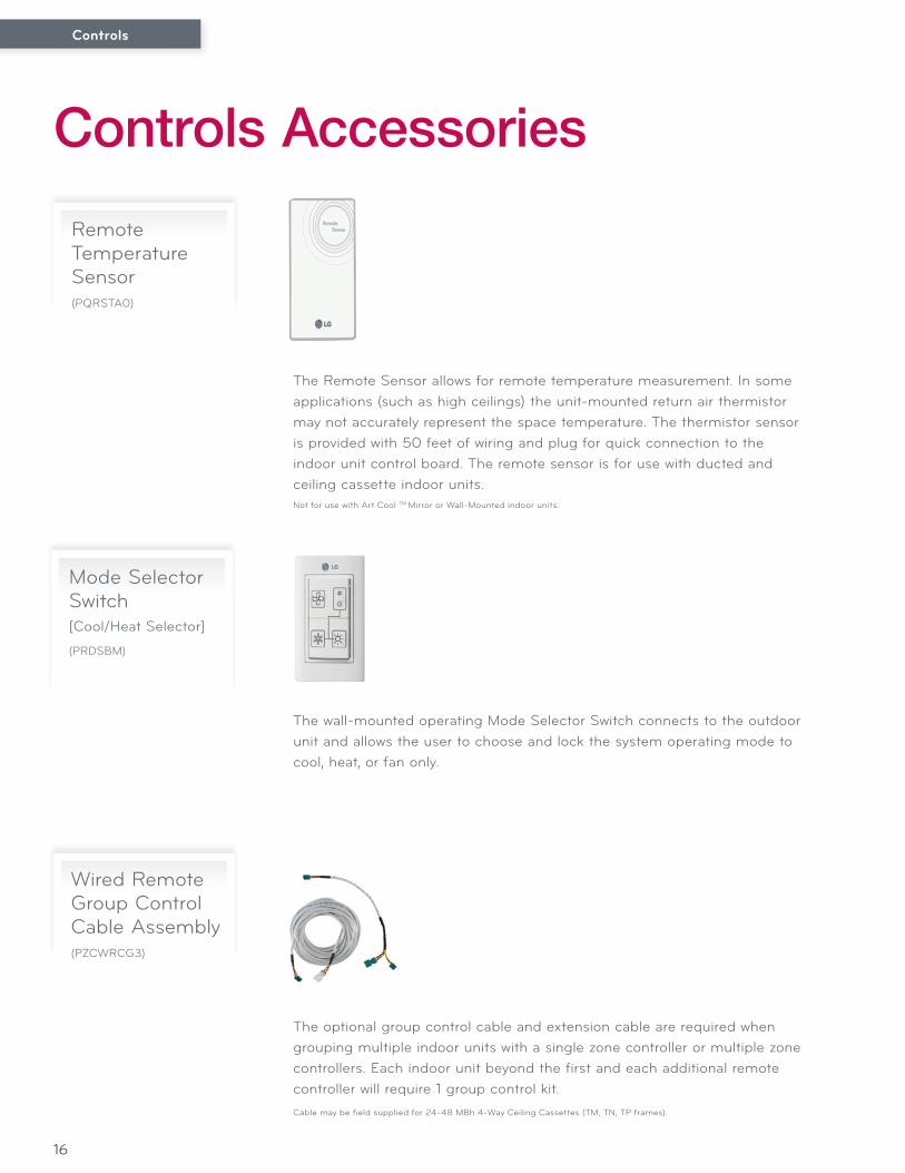
Remote Temperature Sensor(PQRSTA0)
The Remote Sensor allows for remote temperature measurement. In some applications (such as high ceilings) the unit-mounted return air thermistor may not accurately represent the space temperature. The thermistor sensor is provided with 50 feet of wiring and plug for quick connection to the indoor unit control board. The remote sensor is for use with ducted and ceiling cassette indoor units.Not for use with Art Cool TM Mirror or Wall-Mounted indoor units.
Mode Selector Switch[Cool/Heat Selector]
(PRDSBM)
The wall-mounted operating Mode Selector Switch connects to the outdoor unit and allows the user to choose and lock the system operating mode to cool, heat, or fan only.
Wired Remote Group Control Cable Assembly(PZCWRCG3)
The optional group control cable and extension cable are required when grouping multiple indoor units with a single zone controller or multiple zone controllers. Each indoor unit beyond the first and each additional remote controller will require 1 group control kit.Cable may be field supplied for 24-48 MBh 4-Way Ceiling Cassettes (TM, TN, TP frames).
Controls
17
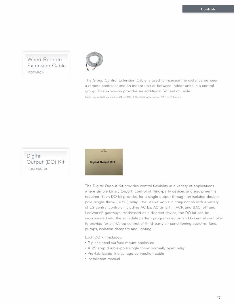
Wired Remote Extension Cable(PZCWRC1)
The Group Control Extension Cable is used to increase the distance between a remote controller and an indoor unit or between indoor units in a control group. This extension provides an additional 32 feet of cable.Cable may be field supplied for 24-48 MBh 4-Way Ceiling Cassettes (TM, TN, TP frames).
Digital Output (DO) Kit(PQNFP00T0)
The Digital Output Kit provides control flexibility in a variety of applications where simple binary (on/off) control of third-party devices and equipment is required. Each DO kit provides for a single output through an isolated double-pole-single-throw (DPST) relay. The DO kit works in conjunction with a variety of LG central controls including AC Ez, AC Smart II, ACP, and BACnet® and LonWorks® gateways. Addressed as a discreet device, the DO kit can be incorporated into the schedule pattern programmed on an LG central controller to provide for start/stop control of third-party air conditioning systems, fans, pumps, isolation dampers and lighting.
Each DO kit Includes:• 2 piece steel surface mount enclosure• A 25 amp double-pole single throw normally open relay• Pre-fabricated line voltage connection cable• Installation manual
Controls
18
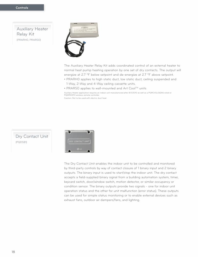
Auxiliary Heater Relay Kit(PRARH0, PRARS0)
The Auxiliary Heater Relay Kit adds coordinated control of an external heater to normal heat pump heating operation by one set of dry contacts. The output will energize at 2.7 ºF below setpoint and de-energize at 2.7 ºF above setpoint.• PRARH0 applies to high static duct, low static duct, ceiling suspended and
1-Way, 2-Way and 4-Way ceiling cassette units.• PRARS0 applies to wall-mounted and Art CoolTM unitsAuxiliary Heater application requires an indoor unit manufactured after 8/1/2010 as well as a PQRCVSL0(QW) wired or PQWRHDF0 wireless remote controller.
Caution: Not to be used with electric duct heat.
Dry Contact Unit(PQDSB1)
The Dry Contact Unit enables the indoor unit to be controlled and monitored by third-party controls by way of contact closure of 1 binary input and 2 binary outputs. The binary input is used to start/stop the indoor unit. The dry contact accepts a field-supplied binary signal from a building automation system, timer, keycard switch, door/window switch, motion detector, or similar occupancy or condition sensor. The binary outputs provide two signals - one for indoor unit operation status and the other for unit malfunction (error status). These outputs can be used for simple status monitoring or to enable external devices such as exhaust fans, outdoor air dampers/fans, and lighting.
Controls
19
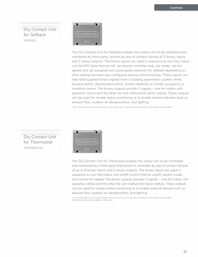
Dry Contact Unit for Setback(PQDSBC)
Dry Contact Unit for Thermostat(PQDSBNGCM1)
The Dry Contact Unit for Setback enables the indoor unit to be controlled and monitored by third-party controls by way of contact closure of 2 binary inputs and 2 binary outputs. The binary inputs are used in sequence to turn the indoor unit On/Off, force thermo-off, set remote controller lock, set mode*, set fan speed, and set occupied and unoccupied setpoints for setback depending on what setting has been pre-configured during commissioning. These inputs can take field supplied binary signals from a building automation system, timer, keycard switch, door/window switch, motion detector, or similar occupancy or condition sensor. The binary outputs provide 2 signals – one for indoor unit operation status and the other for unit malfunction (error status). These outputs can be used for simple status monitoring or to enable external devices such as exhaust fans, outdoor air dampers/fans, and lighting.
The Dry Contact Unit for Thermostat enables the indoor unit to be controlled and monitored by a third party thermostat or controller by way of contact closure of up to 8 binary inputs and 2 binary outputs. The binary inputs are used in sequence to turn the indoor unit on/off, control thermo on/off, control mode1, and control fan speed. The binary outputs provide 2 signals – one for indoor unit operation status and the other for unit malfunction (error status). These outputs can be used for simple status monitoring or to enable external devices such as exhaust fans, outdoor air dampers/fans, and lighting.
* Set mode choices are limited to heat, cool, and fan only. Setting unit to operate in dry mode is not available.
1: Set mode choices are limited to heat, cool, and fan only. Setting unit to operate in dry mode is not available.2: Model specific, not available on all models.
Controls
20
• Option to accumulate standby power consumption• Compatibility with AC Smart II and ACP• Indoor unit power consumption not factored with PDI
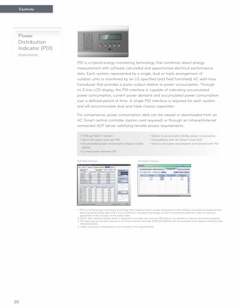
Power DistributionIndicator (PDI)(PQNUD1S01)
PDI is a hybrid energy monitoring technology that combines direct energy measurement with software calculated and apportioned electrical performance data. Each system, represented by a single, dual or triple arrangement of outdoor units is monitored by an LG specified (and field furnished) AC watt-hour transducer that provides a pulse output relative to power consumption. Through its 2-line LCD display, the PDI interface is capable of indicating accumulated power consumption, current power demand and accumulated power consumption over a defined period of time. A single PDI interface is required for each system and will accommodate dual and triple chassis capacities.
For convenience, power consumption data can be viewed or downloaded from an AC Smart central controller (option card required) or through an intranet/internet connected ACP server satisfying remote access requirements.
• 1 PDI per Multi V system• Up to 64 indoor units per PDI• Accumulated power consumption display modes
(kW/h)• Current power demand (W)
1: PDI is a hybrid energy monitoring technology that combines direct energy measurement with software calculated and apportioned electrical performance data. PDI is not a certified or traceable technology. LG and its distribution partners make no claims or guarantees to the accuracy of the output data.
2: ACP’s web interface display shown is required to remotely view and save PDI data on an intranet or internet connected computer.3: PDI data may be remotely read at an AC Smart Central Controller (PQCSW320A1E) with the purchase of an optional interface card
(PQCSE342A0).4: Indoor unit power consumption is not included in the reported data.
ACP Web Interface AC Smart II Output
21
The LG Air ConditioningSupport System
For support with VRF Multi V controls, contractors can contact LG at 1-888-865-3026.

22
Notes

23
Notes
System Controls
Distributed by:
Supersedes: New
LG Electronics USA, Inc. HVAC Division
11405 Old Roswell Road Alpharetta, Georgia 30009
www.lg-vrf.com
For continual prod
uct develop
ment, LG
reserves the right to chang
e specifications w
ithout notice. ©
LG Electronics Inc.
CTRL-PC-CA-001-US 012M13