SYSTEM BOARD USER S MANUAL - | CMA- · PDF fileSYSTEM BOARD USER'S MANUAL DESCRIPTION D0020...
16
SYSTEM BOARD USER' S MANUAL DESCRIPTION D0020 CENTRE FOR MICROCOMPUTER APPLICATIONS http://www.cma-science.nl Figure 1. The System Board
-
Upload
nguyenliem -
Category
Documents
-
view
222 -
download
4
Transcript of SYSTEM BOARD USER S MANUAL - | CMA- · PDF fileSYSTEM BOARD USER'S MANUAL DESCRIPTION D0020...

SYSTEM BOARD USER'S MANUAL
DESCRIPTION D0020
CENTRE FOR MICROCOMPUTER APPLICATIONS
http://www.cma-science.nl
Figure 1. The System Board

2
TTABLE OF CONTENTSABLE OF CONTENTS
I. INTRODUCTION ............................................................................................................................................................. 3
II. ELEMENTS OF THE SYSTEM BOARD ................................................................................................................... 3 2. THE SECTIONS OF THE SYSTEM BOARD .............................................................................................................. 3 3. THE INPUT SECTION ................................................................................................................................................. 5 4. THE PROCESSING SECTION .................................................................................................................................... 6 5. THE OUTPUT SECTION ............................................................................................................................................. 8
III. BUILDING SYSTEMS .................................................................................................................................................. 9 1. INTRODUCTION ............................................................................................................................................................... 9 2. THE AUTOMATIC GARAGE DOOR: : AN EXAMPLARY APPROACH TO SYSTEM BUILDING ................................................... 9
APPENDIX A. TECHNICAL SPECIFICATIONS OF THE SYSTEM BOARD ........................................................ 15
APPENDIX B. WARRANTY AND SAFETY .................................................................................................................. 16

3
S1 S2 S3 S4
I .I . IINTRODUCTION NTRODUCTION The System Board1 is designed for logic, measurement, control and automation practi-cals. Students use the System Board to design and test their self-built automated systems. They get acquainted with digitizing analog signals, processing digital signals and using signals to control actuators. The System Board is powered via an external AC power adapter (230V/9V) and does not have an On/Off switch. Simply plug it in the wall socket and it is ready for use. Part I of this manual describes the various elements of the System Board. Part II gives guidelines for building systems with the System Board and large number of problems, ranging from simple to difficult, which your students can solve. Appendix A contains the Board’s technical specifications and in Appendix B the warranty is described as well some tips for safely using the System Board.
I I .I I . EELEMENTS OF THE LEMENTS OF THE SSYSTEM YSTEM BBOARD OARD
1. The sections of the System Board Data processing systems can be described with the aid of the block diagram in figure 1. If we take a person as an example of a data processing system, then the functions of the sections can be given with look, think and do.
Figure 2. A block diagram of a general data processing system
The elements of the System Board are grouped likewise into three sections: Input (left column); Processing (center column) and Output (right column).
The Input section (‘Invoer’) is the subsystem which gathers data from the environment and conditions the signal S1 (which carries the data) to make it suitable for processing. The input section consists of two general sensor inputs, a sound sensor, two push buttons, a variable voltage, a pulse generator and an AD-converter.
The Processing section (‘Verwerking’) is the subsystem which processes the signal S2 to achieve a specific system goal. This section consists of two comparators for processing analog signals and for processing digital signals, two AND ports, an OFF port, two invertors, a memory cell and a pulse counter.
1 The System Board is originally designed for Dutch education. So all labels are Dutch. In this manual, the Dutch texts are
written behind the English names, where necessary.
INPUT Look
OUTPUT Do
PROCESSING Think

4
The Output section (‘Uitvoer’) is the subsystem which presents the processed data S3 in a useful form for the user or which carries out an action based on the signals. This section consists of four LEDs, a buzzer and relay. On the next pages a short description of these elements is given.
Figure 3. The front of the System Board

5
2. The INPUT section (ʻINVOERʼ) Sensors convert physical quantities (temperature, sound, light intensity etc.) into an electrical signal. The System Board has built in: a sound sensor (‘geluidsensor’) and push buttons (‘drukschakelaar’), and two general-purpose sensor inputs. The sound sensor gives a signal between 0 and 5V depending upon the sound level of the signal. The push buttons give a 5V signal whilst the button is pressed, and else 0V. The sensor inputs are prepared for CMA sensors (4 mm or BT). Also other type of sensors can be connected if the sensors meet the input specifications (see page 15 of this manual).
2.1 Adjustable signal sources The System Board has two signal sources: a variable dc voltage (0…5V) (‘Variabele spanning’) and a pulse generator (‘puls- generator’) which produces a 5V square wave with a frequency which can be set between 1 and 10 Hz. The variable dc source is used for testing (sub)systems. Next to the knob is the earth socket to allow the signal to be measured with a voltmeter. The pulse generator is used mainly in combination with the counter to build time dependent functions (eg. a four second delay before an alarm sounds).
2.2 AD-converter
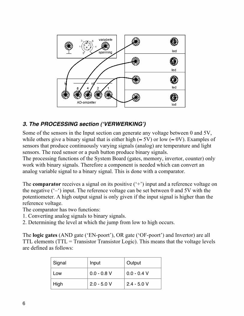
A 4-bit analog to digital converter (ADC – ‘AD-omzetter’)2 is used to give pupils insight into the role of analog to digital conversion, and the caused loss of information. Pupils can experience that the limited number of signal codes gives rise to a limitation of resolution (i.e. the 5V analog signal is converted to only 16 digital levels).
2 Actually the 4 most significant bits of 8-bits converter are used.
EXPERIMENT: Connect each of the outputs of the ADC to a LED and connect the variable voltage to the input. See the circuit on the next page. Investigate the ADC.
6
3. The PROCESSING section (ʻVERWERKINGʼ) Some of the sensors in the Input section can generate any voltage between 0 and 5V, while others give a binary signal that is either high (≈ 5V) or low (≈ 0V). Examples of sensors that produce continuously varying signals (analog) are temperature and light sensors. The reed sensor or a push button produce binary signals. The processing functions of the System Board (gates, memory, invertor, counter) only work with binary signals. Therefore a component is needed which can convert an analog variable signal to a binary signal. This is done with a comparator. The comparator receives a signal on its positive (‘+’) input and a reference voltage on the negative (‘–‘) input. The reference voltage can be set between 0 and 5V with the potentiometer. A high output signal is only given if the input signal is higher than the reference voltage. The comparator has two functions: 1. Converting analog signals to binary signals. 2. Determining the level at which the jump from low to high occurs. The logic gates (AND gate (‘EN-poort’), OR gate (‘OF-poort’) and Invertor) are all TTL elements (TTL = Transistor Transistor Logic). This means that the voltage levels are defined as follows:
Signal Input Output
Low 0.0 - 0.8 V 0.0 - 0.4 V
High 2.0 - 5.0 V 2.4 - 5.0 V

7
The AND and OR ports each have two inputs and one output. The output of an AND Gate is only high if both of its inputs are high. The output of an OR Gate is high if either of its inputs is high. Otherwise the output will be low. The Invertor gives a low output if the input is high and vice versa. With these ports binary signals can be processed.
The Memory cell (‘geheugencel’) is a set/reset latch and is mainly used to hold signals at a high level, e.g. an alarm which must remain on, even once the burglar has left.
The counter is used to count events (eg. counting packets on a conveyor belt) or to build a delay into a system (e.g. a baby alarm, which should only be activated once the baby has cried for some time). The number of pulses counted can be read from the decimal display, or in binary form on the four numbered outputs. To help pupils to become familiar with binary counting, these outputs can be connected to the 4 LEDs in the output section. The signals on the LEDs can be compared with the number on the display. The counter has three inputs: Clock: (‘tel pulsen’)
Each time this input changes from low to high the count is increased by one. By connecting this input to the pulse generator, the counter can be used for timing.
Counter On/Off: (‘tellen aan/uit’)
By default this input is high (counter ON). If this input is made low, the counter stops.
Reset: By making this input high the counter will be set to zero.
EXPERIMENT: Make a truth table for the AND and OR gates. Connect the inputs to the push buttons and the inputs and outputs to LEDs.
EXPERIMENT: Test how the set and reset inputs work by connecting them to push buttons. Connect the input and outputs to LEDs.
EXPERIMENT: Build the circuit shown on the next page. The circuit will count and display binary digits. Use the push buttones to give pulses on the clock input.
Input1 Input2 AND OR On On On On Off On Off On On Off Off On Off Off Off Off
Truth table for the AND and OR-ports.

8
4. The OUTPUT section (ʻUITVOERʼ) The processed signals can control LEDs (e.g. as indicator lights), a buzzer or an electrical device connected to the relay, which can switch devices up to 75 W (30V, 2.5A). The switching point is approximately 1.4 V.3 As mentioned before, the LEDs are also used to count binary numbers, and to show the operation of an AD converter. The LEDs are furthermore useful to trace problems or perform tests when systems are being built.
3 The CMA heating element (art. nr 018) (Vmax = 24 V) is suitable for use with the relay.
EXPERIMENT: Connect the heater and power supply to the relay. Use a push button to switch the heater on and off. See the diagram below.

9
I I I .I I I . BBUILDING SYSTEMS UILDING SYSTEMS
1. Introduction In this section a general procedure is described for building automated systems with the System Board. During the development of systems the following strategy can be used: • Think about the sensors (Input) and actuators (Output), which will be necessary to
meet the system specification(s); • Split the problem into smaller sub-problems; • Design a solution for each of sub-problems; • Build and test the subsystems; • Design a system which solves the whole problem; • Combine the subsystems to form the solution to the whole problem; • Evaluate the solution.
2. The automatic garage door: an exemplary approach to system building
The problem A car stands in front of a garage. If the horn sounds loud enough and longer than 2 seconds, the garage door must open. To avoid noise nuisance, it should also be possi-ble to open the garage door with a push button. When the door is fully open, it should hit a second switch to switch off the motor.
Finding the inputs and outputs
Input: A sound sensor to detect sound Two push buttons: one to signal the door to open and the second one to stop the motor once the door is open. A pulse generator (to count 2 seconds)
Output: A motor connected to the relay (for reasons of simplicity the relay is replaced by a LED in this description).
Dividing the problem into sub-problems The problem can be divided into four sub-problems.
Sub-problem 1 The system must only react to sufficiently loud sounds.
Solution - Connect the sound sensor to a comparator. - Set the reference voltage at 4V. - Connect the output of the comparator to a LED.
Solution of sub-problem 1

10
- Test the circuit for high and low sound level.
Sub-problem 2 The system must be able to measure whether the sound signal lasts for at least 2 seconds.
Solution - Set the pulse generator on 1 Hz (i.e. 1 pulse per s) - Connect the pulse generator to the counter’s clock
input. - Connect the motor (read: LED) to the 2-output. - Count with the clock until the 2-output is high. - When the horn sounds the counter must be reset to zero. In this phase you can
imitate this by connecting a push button to the 'reset' input of the counter. (Whilst the switch is pressed the counter position is and remains zero, and when the switch is released, the counter starts counting from zero).
Sub-problem 3 In sub-problem 2 the system is switched off (the motor stops) as soon as the counter displays 4 (then the 4 pin is on). This is un-desired as the door should not stop half-way. When the door is fully opened it should press a button to stop the motor.
Solution - Connect the 2-output of the counter with the 'set' input of the memory cell. - Connect the second push button to the 'reset' input of the memory cell.
Combining subsystems 1 to 3 A low sound level should block the counter via a high signal on the 'reset' input of the counter. Subsystem 1 must supply a low signal at low sound level. Because of this the subsystem 1 must be connected through an invertor to the 'reset' input of the counter.
Solution of sub-problem 2
Solution of sub-problem 3
Combining subsystems 1 to 3
11
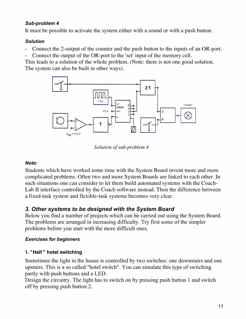
Sub-problem 4 It must be possible to activate the system either with a sound or with a push button.
Solution - Connect the 2-output of the counter and the push button to the inputs of an OR-port. - Connect the output of the OR-port to the 'set' input of the memory cell. This leads to a solution of the whole problem. (Note: there is not one good solution. The system can also be built in other ways).
Note: Students which have worked some time with the System Board invent more and more complicated problems. Often two and more System Boards are linked to each other. In such situations one can consider to let them build automated systems with the Coach-Lab II interface controlled by the Coach software instead. Then the difference between a fixed-task system and flexible-task systems becomes very clear. 3. Other systems to be designed with the System Board Below you find a number of projects which can be carried out using the System Board. The problems are arranged in increasing difficulty. Try first some of the simpler problems before you start with the more difficult ones.
Exercises for beginners
1. "Half " hotel switching Sometimes the light in the house is controlled by two switches: one downstairs and one upstairs. This is a so called "hotel switch". You can simulate this type of switching partly with push buttons and a LED. Design the circuitry. The light has to switch on by pressing push button 1 and switch off by pressing push button 2.
Solution of sub-problem 4
12
2. Flashing light
Flashing lights are often used to warn in unsafe traffic situations. Design a fast flashing light (aprox. 0.5s on, 0.5s off, 0.5s on, etc.).
3. School bell A school bell operates about 3 s. Design a circuitry which turns on the buzzer for 3 s after pressing the push button. The system has to reset itself automatically to be ready for the next pressing.
4. Switch with delay
When you switch off the light in the room then immediately you stay in the dark and sometimes it is risky to reach the door. A good solution to prevent this is a switch which turns off the light with a delay. Design a system which turns on the LED immediately after the switch is pushed and turns off the LED 6 s after the switch is pushed again.
5a. The conveyor belt 1
Fragile packages are transported on a conveyor belt. These packages have to be packed: eight packages in one large box. In case of an emergency, there is a stop button to prevent damage with the fragile packages. Design a system which runs the conveyor belt unless the emergency stop button is pressed. Hint: A LED simulates the running conveyor belt. The emergency stop button is push
button 1. When the push button is pressed the conveyor belt is stopped immediately. As soon as the push button is released the belt will run again.
5b. The conveyor belt 2 Adapt the system of the exercise 5a so that the conveyor belt stops with the push button and still halts after the push button is released. With the second push button the conveyor belt can be started again.
6. The burglar alarm 1 If a burglar interrupts a light beam an alarm will sound. The owner of the house can switch off the alarm by simply pushing a button. Design a circuitry for this antitheft system. Apply a strong light beam (for example desk lamp) with a much higher light intensity than the background light.
7. A wind-sensitive sun shield 1 Sun shields are handy with sunny weather but they are vulnerable for wind. With a wind speedometer as a sensor we will measure the wind speed. In case of strong wind an electrical motor has to start and roll away the sun shield. When it is fully rolled
13
away, one arm of the shield presses a push button to stop the motor. Design a system that rolls away the shield with strong wind. The variable voltage will function here as a sensor. When the voltage is larger then 2.5V the wind is too strong. Simulate the motor with the LED. If the LED is on, this indicates that the motor is running. The LED has to switch off when the push button stays pushed.
Exercises for experienced users
8. The car alarm 1 A deliveryman does not like to close his car at each address. The idea is to create an alarm that switches on when the key is taken out of the starter lock. The alarm should switch on also when the door is opened for longer than 8 s. In this problem the 8s is enough time for the driver to step out and in the car (so it is a very fast deliveryman!). It is possible to switch off the alarm only with the key of the car. Design this alarm system. Use push button 1 as the starter lock; when pressed it means that the key is in the lock. Use push button 2 as the door; when pressed it means that the door is open. Use a LED to show whether the alarm is on/off.
9. The conveyor belt 3
It turns out that in emergency situations the emergency stop button is pressed too late. This causes a lot of damage. One decided to count the number of packages on the conveyor belt. After counting 8 packages the belt stops automatically. The operator starts the conveyor belt again by pressing a button. The packages are counted with the light sensor. When the light is interrupted by a package the voltage of the sensor is between 0.5V - 1.5V and depending on the background light in other situations about 3V. Design a system that controls the conveyor belt in this way. Hint: The counter reacts at changing signal from low to high. You might use a lamp to
light a light sensor.
10a. The lighthouse 1 In lighthouses the on/off rhythm is realized by covering or uncovering the light. So the lamp is constantly on. Nowadays we do not waste energy, so to safe energy the lamp should actually be switched on and off. Design a system which controls the lamp in the following way: 2 s on and 6 s off, etc. Use the LED as the lamp.
10b. The lighthouse 2 It is not necessary that the lighthouse operates at day time. Adapt the system 10a in such a way that it operates only when it starts to get dark and during the night. Hint: Use a lamp to simulate enough daylight and assume it is daylight as long as the
sensor gives off a voltage larger than 3V.

14
11. Stopwatch
The stopwatch is used often for sports. Our stopwatch is not really good, because it can only measure whole seconds with a maximum of 9 s. The stopwatch is started with a push on a switch and is stopped by pushing on another switch. By pressing both switches on the same time the stopwatch will be reset.
12. An elevator
You enter an elevator and choose the right floor with the push button. After 4 s the door closes automatically unless someone stays between the door. Task: build an elevator control system with a safe door. The latter is realized by a light beam that is shining on the light sensor and will be interrupted when someone is in the door post. Simulate the door with a LED (LED=on means door=closed).
13. The burglar alarm 2
When a burglar interrupts a light beam an alarm will sound. The alarm can be turned off by the house owner by simply pressing a button. When the owner is not at home the alarm has to stop automatically after 8s and return to its initial situation. Design a system to realize the above, apply a strong light source (for instance desktop lamp) which has a light intensity much higher than the intensity of the background light.
14. The washing machine
A washing machine has to perform many different tasks. Here we will concentrate on a small part of the complete washing cycle: the heating element must be switched on until the desired temperature is reached. As soon this is the case, it has to turn off and the motor should start running for 8s. After this 8s the motor has to stop also and our part ends. Design a circuitry that realizes this part of the cycle. Apply amongst others a temperature sensor, a glass with cold water and a glass with hot water. Determine first the voltage of the temperature sensor on which you decide the water is warm enough. Simulate the heating element with LED 1 (LED = on means heating = on) and the motor with LED 4 (LED on = motor on).

15
APPENDIXAPPENDIX A.A. TECHNICALTECHNICAL SPECIFICATIONSSPECIFICATIONS OFOF THETHE SYSTEMSYSTEM
BOARDBOARD External sensors Supply provided: 5 V, 100 mA (total),
4mm input (red = +5V, black = earth, yellow = signal) BT-plug input
Sound sensor Gives a signal which is directly proportional to the sound level. Output: 0 - 5 V, impedance: 500 Ω
Push buttons Debounced output, TTL levels (LS TTL)
Variable voltage Range: 0 - 5 V, Impedance: 330 Ω
Pulse generator Range: 1 - 10 Hz, Impedance: 330 Ω
AD-converter ADC0804, 8-bits converter with the 4 most significant bits available; Measuring frequency ≈ 10 kHz, Input impedance 1 MΩ
Comparator Non-inverting, reference level adjustable: 0 - 5 V Hysteresis 50 mV, Input impedance: 100 kΩ
AND gate, OR gate Invertor, Latch (SR-flip-flop)
Inputs: switching level ≈ 1.4 V Impedance 10 kΩ Unconnected inputs are LOW!
Pulse counter Decade-counter (74HCT160) 'clock' (tel pulsen) and 'count enable' (teller aan/uit) are inputs with 10 kΩ pull-up, Unconnected are HIGH Reset: switching level ≈ 1.4 V, Impedance 10 kΩ Unconnected is LOW
LEDs Switching point ≈ 1.4 V, Impedance 10 kΩ Unconnected are LOW (LED off)
Buzzer Input current at 5 V in: 0.33 mA Unconnected is LOW.
Relay Input: switching point ≈ 1.4 mV, Impedance 10 kΩ Unconnected is LOW Output: DC max. 30 V, 2.5 A; AC max. 30 V, 2.5 A Output protected with Multifuse (automatic fuse)
16
APPENDIXAPPENDIX B.B. WWARRANTY AND SAFETY ARRANTY AND SAFETY
Warranty The System Board is guaranteed completely for product quality during 12 months after the date of purchase. Any damage caused by operation contrary to the prescriptions in this manual is excluded from this guarantee.
Safety
• Use only the included power supply adapter and plug the round plug of the power adapter into the bus on the rear side of System Board.
• Never connect the relay's black terminal posts to other sockets of the System Board. • All the other sockets on the board can be connected together without risk of damage. • No more than 5 V should be connected to the System Board's sockets, with the
exceptions of the black terminal posts of the relay. • The relay can be used with supplies of up to 30 V. The 30 V maximum is chosen as
a limit for safety of students. N.B.: Failure to use the System Board according to these regulations may result in
damage the electronics of the System Board.
Warranty: System Board (020) is warranted to be free from defects in materials and workmanship for a period of 12 months from the date of purchase provided that it has been used under normal laboratory conditions. This warranty does not apply if the System Board has been damaged by accident or misuse.
Note: This product is to be used for educational purposes only. It is not appropriate for industrial, medical, research, or commercial applications.
Rev. 18/06/13