
System and Component Descriptions, Boundaries, and...
91
System and Component Descriptions, Boundaries, and Failure Modes
Transcript of System and Component Descriptions, Boundaries, and...

System and Component Descriptions, Boundaries, and Failure Modes
Introduction General Guidance on Failure Coding
iii
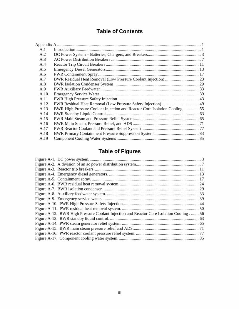
Table of Contents Appendix A ..................................................................................................................................... 1
A.1 Introduction.................................................................................................................... 1 A.2 DC Power System – Batteries, Chargers, and Breakers................................................. 3 A.3 AC Power Distribution Breakers ................................................................................... 7 A.4 Reactor Trip Circuit Breakers ...................................................................................... 11 A.5 Emergency Diesel Generators...................................................................................... 13 A.6 PWR Containment Spray ............................................................................................. 17 A.7 BWR Residual Heat Removal (Low Pressure Coolant Injection) ............................... 23 A.8 BWR Isolation Condenser System............................................................................... 29 A.9 PWR Auxiliary Feedwater ........................................................................................... 33 A.10 Emergency Service Water............................................................................................ 39 A.11 PWR High Pressure Safety Injection ........................................................................... 43 A.12 PWR Residual Heat Removal (Low Pressure Safety Injection) .................................. 49 A.13 BWR High Pressure Coolant Injection and Reactor Core Isolation Cooling............... 55 A.14 BWR Standby Liquid Control...................................................................................... 63 A.15 PWR Main Steam and Pressure Relief System............................................................ 65 A.16 BWR Main Steam, Pressure Relief, and ADS ............................................................. 71 A.17 PWR Reactor Coolant and Pressure Relief System ..................................................... 77 A.18 BWR Primary Containment Pressure Suppression System ......................................... 83 A.19 Component Cooling Water Systems ............................................................................ 85
Table of Figures Figure A-1. DC power system........................................................................................................ 3 Figure A-2. A division of an ac power distribution system............................................................ 7 Figure A-3. Reactor trip breakers. ................................................................................................ 11 Figure A-4. Emergency diesel generators. ................................................................................... 13 Figure A-5. Containment spray. ................................................................................................... 17 Figure A-6. BWR residual heat removal system.......................................................................... 24 Figure A-7. BWR isolation condenser. ........................................................................................ 29 Figure A-8. Auxiliary feedwater system. ..................................................................................... 33 Figure A-9. Emergency service water. ......................................................................................... 39 Figure A-10. PWR High Pressure Safety Injection...................................................................... 44 Figure A-11. PWR residual heat removal system. ....................................................................... 50 Figure A-12. BWR High Pressure Coolant Injection and Reactor Core Isolation Cooling . ....... 56 Figure A-13. BWR standby liquid control. .................................................................................. 63 Figure A-14. PWR steam generator relief system. ....................................................................... 65 Figure A-15. BWR main steam pressure relief and ADS............................................................. 71 Figure A-16. PWR reactor coolant pressure relief system. .......................................................... 77 Figure A-17. Component cooling water system........................................................................... 85

Introduction General Guidance on Failure Coding
iv

Introduction General Guidance on Failure Coding
1
System and Component Descriptions,
Boundaries, and Failure Modes
1 Introduction
This appendix presents the component definitions, boundaries, and failure modes for the components analyzed in the CCF data collection task for the NRC.
Components are grouped by the system they are analyzed in. Each major section presents a system. Within that section, the components of interest are described, their safety function and PRA function defined, and the boundaries used in the analysis are defined. Simple diagrams are presented showing the most common configuration and numbers of components installed. The failure modes applicable to each component are defined and guidance is given on failure event characteristics applicable to each failure mode.
1.1 General Guidance on Failure Coding The following guidance is presented to provide the analyst with guidance on the coding of
CCF events and so that the user can understand what the CCF events are comprised of.
Conditions related to potential failure due to seismic design, environmental qualification, or other similar concerns are not considered in this data collection effort. Any inoperability declared strictly for administrative reasons are not considered failures (e.g. a surveillance test not performed within the required time frame).
Many of the components in the CCF database are required to operate in an automatic mode (e.g., ESF actuation). If the automatic function is not operable, the component is coded as a complete failure to function (p-value = 1.0) even though the component may be operated in the manual mode.
Failures detected during troubleshooting or when the component would not reasonably be considered fully capable, such as after major maintenance are not considered failures. However, if a failure occurred on equipment other than what had been repaired during an operational surveillance test following maintenance, another failure is to be counted.
Some of the tests have acceptance criteria expressed as a percentage of a value. The CCF database only contains failures due to test results out of acceptable range, when the result is greater than 10 percent out of acceptable range. The exception to this rule is if the mechanism creating the out of acceptable range results is a true failure mechanism (i.e., not the general setpoint drift).
In many cases, the room cooling is failed or subject to failure. The room cooling is not included in the component boundary of any of the components in the CCF study. In addition, most PRAs model room cooling as a separate event, which usually indicates that the equipment can run for some period before it fails. Therefore, room-cooling failures are not to be included in the failure records for either independent or CCF events.
Many events refer to the failure of the min-flow recirculation function for a pump. The failure to create minimum flow can lead to pump over-heating and damage, but only after enough time has elapsed. The failure to shut off minimum flow can reduce the
Introduction General Guidance on Failure Coding
2
flow to the target. Both of these conditions are minimally degraded states and should not be coded as anything more than 0.1 p-values.
A CCF component, pump volute (PMP), has been created to allow CCF events across pump types (e.g., MDP and TDP). The basic events will be coded as their pump type and the CCF event will be coded as PMP to show that these events are applicable only for the pump volute segment and can be used across pump types.
DC Power System – Batteries, Chargers, and Breakers Battery Chargers
3
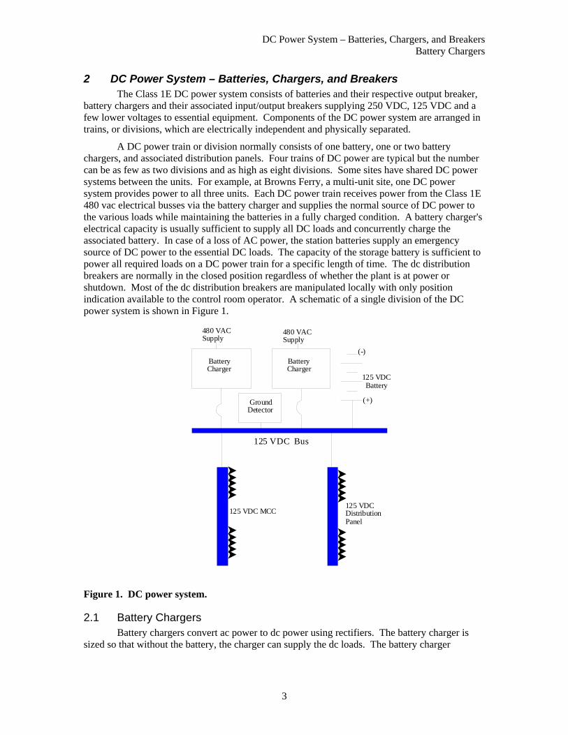
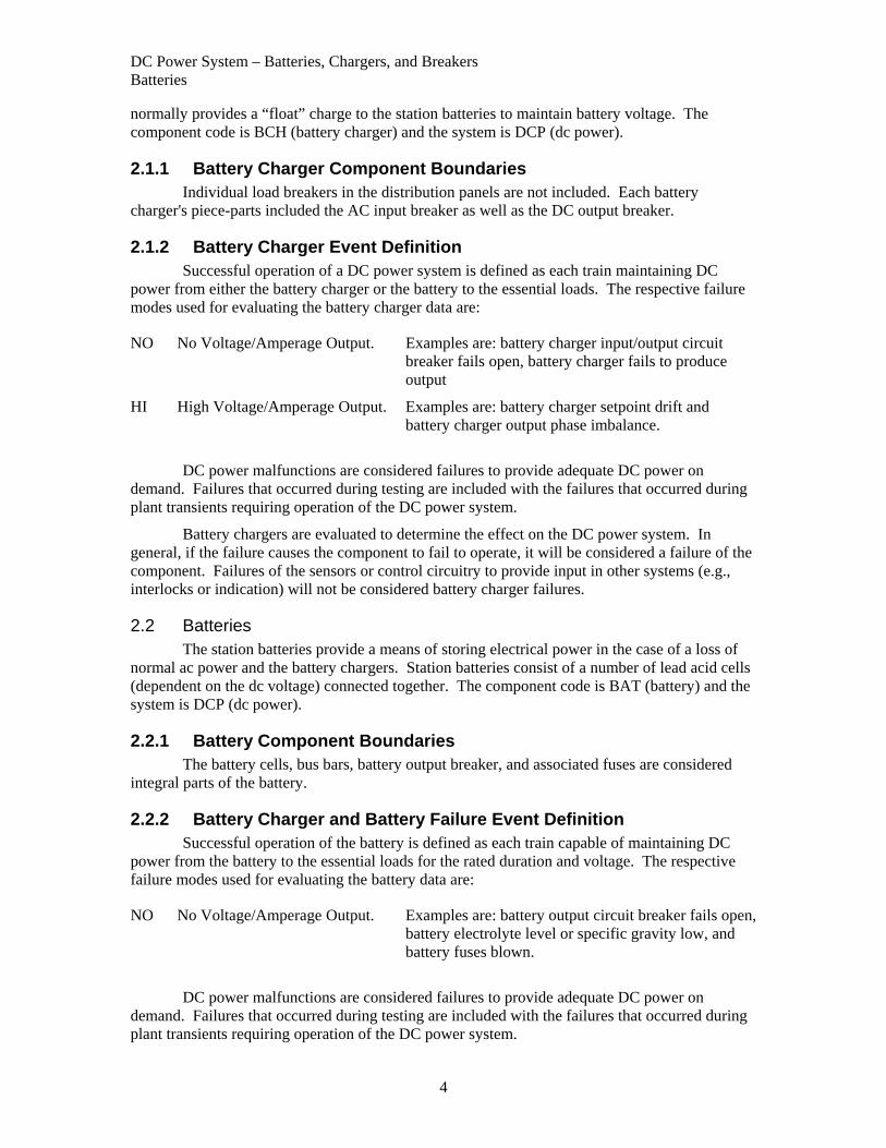
2 DC Power System – Batteries, Chargers, and Breakers The Class 1E DC power system consists of batteries and their respective output breaker, battery chargers and their associated input/output breakers supplying 250 VDC, 125 VDC and a few lower voltages to essential equipment. Components of the DC power system are arranged in trains, or divisions, which are electrically independent and physically separated.
A DC power train or division normally consists of one battery, one or two battery chargers, and associated distribution panels. Four trains of DC power are typical but the number can be as few as two divisions and as high as eight divisions. Some sites have shared DC power systems between the units. For example, at Browns Ferry, a multi-unit site, one DC power system provides power to all three units. Each DC power train receives power from the Class 1E 480 vac electrical busses via the battery charger and supplies the normal source of DC power to the various loads while maintaining the batteries in a fully charged condition. A battery charger's electrical capacity is usually sufficient to supply all DC loads and concurrently charge the associated battery. In case of a loss of AC power, the station batteries supply an emergency source of DC power to the essential DC loads. The capacity of the storage battery is sufficient to power all required loads on a DC power train for a specific length of time. The dc distribution breakers are normally in the closed position regardless of whether the plant is at power or shutdown. Most of the dc distribution breakers are manipulated locally with only position indication available to the control room operator. A schematic of a single division of the DC power system is shown in Figure 1.
BatteryCharger
GroundDetector
(-)
(+)
125 VDCBattery
125 VDC MCC125 VDC DistributionPanel
125 VDC Bus
480 VACSupply
480 VACSupply
BatteryCharger
Figure 1. DC power system.
2.1 Battery Chargers Battery chargers convert ac power to dc power using rectifiers. The battery charger is
sized so that without the battery, the charger can supply the dc loads. The battery charger
DC Power System – Batteries, Chargers, and Breakers Batteries
4
normally provides a “float” charge to the station batteries to maintain battery voltage. The component code is BCH (battery charger) and the system is DCP (dc power).
2.1.1 Battery Charger Component Boundaries Individual load breakers in the distribution panels are not included. Each battery charger's piece-parts included the AC input breaker as well as the DC output breaker.
2.1.2 Battery Charger Event Definition Successful operation of a DC power system is defined as each train maintaining DC power from either the battery charger or the battery to the essential loads. The respective failure modes used for evaluating the battery charger data are:
NO No Voltage/Amperage Output. Examples are: battery charger input/output circuit breaker fails open, battery charger fails to produce output
HI High Voltage/Amperage Output. Examples are: battery charger setpoint drift and battery charger output phase imbalance.
DC power malfunctions are considered failures to provide adequate DC power on demand. Failures that occurred during testing are included with the failures that occurred during plant transients requiring operation of the DC power system.
Battery chargers are evaluated to determine the effect on the DC power system. In general, if the failure causes the component to fail to operate, it will be considered a failure of the component. Failures of the sensors or control circuitry to provide input in other systems (e.g., interlocks or indication) will not be considered battery charger failures.
2.2 Batteries The station batteries provide a means of storing electrical power in the case of a loss of
normal ac power and the battery chargers. Station batteries consist of a number of lead acid cells (dependent on the dc voltage) connected together. The component code is BAT (battery) and the system is DCP (dc power).
2.2.1 Battery Component Boundaries The battery cells, bus bars, battery output breaker, and associated fuses are considered integral parts of the battery.
2.2.2 Battery Charger and Battery Failure Event Definition Successful operation of the battery is defined as each train capable of maintaining DC power from the battery to the essential loads for the rated duration and voltage. The respective failure modes used for evaluating the battery data are:
NO No Voltage/Amperage Output. Examples are: battery output circuit breaker fails open, battery electrolyte level or specific gravity low, and battery fuses blown.
DC power malfunctions are considered failures to provide adequate DC power on demand. Failures that occurred during testing are included with the failures that occurred during plant transients requiring operation of the DC power system.
DC Power System – Batteries, Chargers, and Breakers DC Power Distribution Circuit Breakers
5
Battery failures are evaluated to determine the effect on the DC power system. In general, if the failure causes the component to fail to operate, it will be considered a failure of a DC power train.
2.3 DC Power Distribution Circuit Breakers The DC distribution breakers are normally in the closed position regardless of whether the plant is at power or shutdown. Most of the DC distribution breakers are manipulated locally with only instrumentation available to the control room operator.
2.3.1 DC Circuit Breakers Component Boundaries The safety function of a DC circuit breaker is to connect a power source to a load, monitor the current flow through the breaker, and isolate the load from the source if the current demand exceeds the design current flow or when an external trip signal is initiated. This action protects both the source and the load from equipment damage and executes the design function of the breaker.
DC circuit breakers have overcurrent protection that is a built in part of breaker unit. Most circuit breakers, especially for safety related equipment applications, provide additional protection by monitoring such parameters as under voltage, ground faults, and other protection schemes as required for breaker/system protection or the specific safety application. This additional application hardware is generally located exterior to the circuit breaker and merely utilizes the remote operating features of the breaker. This hardware as well as the remote operating hardware is considered integral to the function of the circuit breaker and part of the breaker for failure analysis. It includes all sensing devices, cabling, and components necessary to process the signals and provide control signals to the individual breaker.
2.3.2 DC Circuit Breakers Failure Event Definition Successful DC distribution breakers system response to a demand requires that DC electrical power is available to the required safety related loads for the duration of the mission time. The failure modes used in evaluating the DC distribution breakers data are:
OO Failure to Close The breaker did not close or would not have been able to close if a close signal had been generated. A failure reported as a miscalibration with no indication of high or low will be coded as "CC."
CC Failure to Open A breaker found open when it should have been closed, with no indication that it had ever been closed, and incapable of actuating due to physical block (e.g. locked or actually out of the cabinet).
SA Failure to Remain Closed (Spurious Operation)
The breaker opened when it should have stayed closed or closed inadvertently, because of a breaker fault within the component boundary. Some reports state that the breaker was found in the tripped condition; these are considered SA. Also included are spurious operations of the breaker due to personnel error, bumping the cabinet, or radio interference.
Many reports indicate that breakers have spuriously actuated due to a system fault, which causes an overcurrent or undervoltage condition, and the breaker trips as designed for protective

DC Power System – Batteries, Chargers, and Breakers DC Power Distribution Circuit Breakers
6
function. Any response of the breaker in which the breaker acts as designed will not be coded as a failure. However, a fault within the circuit breaker component boundary that causes an inadvertent trip or closure would be a SA.

AC Power Distribution Breakers 4160 vac and 6.9Kva Distribution Circuit Breakers
7
3 AC Power Distribution Breakers The AC electrical power distribution system supplies power to safety related and non-safety related large loads. For the purpose of this study, only those breakers supplying safety related loads are to be considered. These breakers are normally operated remotely but may also be locally operated in most cases. Figure 2 shows a division of a typical AC power distribution system. The circuit breakers considered in this study are enclosed in boxes. Circuit breakers that supply individual components (e.g. safety injection pumps) are not included in this study, but are included in the component studies as a part of the individual component. Breakers used to supply power from an emergency diesel generator (EDG) to a 4160-volt bus are specifically excluded and are considered under a separate study of EDGs (Section 5)
Off-Site Power
6.9 KV or 4160 Volts
480Volts
6.9 KV or 4160 Volt AC Loads
480 Volt MCCs120Volts
MainGeneratorOutput24 KV345 KV
6.9 KV or 4160 Volts
CircuitBreaker
Circuit Breaker
Transformer
DC MCCs
Figure 2. A division of an ac power distribution system.
3.1 4160 vac and 6.9Kva Distribution Circuit Breakers 4160 vac and/or 6.9Kva distribution breakers supply power to 4160 vac or 6.9Kva
distribution centers or smaller electrical distribution centers (480 vac motor control center). Breakers, which supply power to 4160-volt or 6.9Kva busses, as well as breakers supplying distribution centers from the 4160-volt or 6.9Kva busses, are considered. The component code is CB4 (4160 vac circuit breaker) or CB3 (6.9Kva circuit breaker) and the system is ACP (ac power).
3.1.1 4160 vac and 6.9Kva Distribution Circuit Breaker Component Boundaries
The super component, the 4160 vac or 6.9Kva circuit breaker, is defined as the breaker itself and the equipment contained in the breaker cubicle. External equipment used to monitor under voltage, ground faults, differential faults, and other protection schemes for individual breakers are considered part of the breaker.

AC Power Distribution Breakers 480 vac Distribution Circuit Breakers
8
AC circuit breakers have overcurrent protection that is integral to the breaker unit. Most circuit breakers, especially for safety related equipment applications, provide additional protection by monitoring such parameters as under voltage, differential faults, ground faults, and other protection schemes as required for breaker/system protection or the specific safety application. This additional application hardware is generally located external to the circuit breaker and merely utilizes the remote operating features of the breaker. This hardware, as well as the remote operating hardware, is considered integral to the function of the circuit breaker for failure analysis. It includes all sensing devices, cabling, and components necessary to process the signals and provide control signals to the individual breaker.
3.1.2 4160 vac and 6.9Kva Distribution Circuit Breaker Failure Event Definition
Successful 4160 vac or 6.9Kva circuit breaker response to a demand requires that the 4160 vac circuit breaker provide electrical power to the bus or load for the duration of the mission time. The failure modes used in evaluating the 4160 vac or 6.9Kva circuit breaker data are:
OO Failure to Close The breaker did not close or would not have been able to close if a close signal had been generated. A failure reported as a miscalibration with no indication of high or low will be coded as "CC."
CC Failure to Open A breaker found open when it should have been closed, with no indication that it had ever been closed, and incapable of actuating due to physical block (e.g. locked or actually out of the cabinet).
SA Failure to Remain Closed (Spurious Operation)
The breaker opened when it should have stayed closed or closed inadvertently, because of a breaker fault within the component boundary. Some reports state that the breaker was found in the tripped condition; these are considered SA. Also included are spurious operations of the breaker due to personnel error, bumping the cabinet, or radio interference.
Many reports indicate that breakers have spuriously actuated due to a system fault, which causes an overcurrent or undervoltage condition, and the breaker trips as designed for protective function. Any response of the breaker in which the breaker acts as designed will not be coded as a failure. However, a fault within the circuit breaker component boundary that causes an inadvertent trip or closure would be a SA.
3.2 480 vac Distribution Circuit Breakers 480 vac distribution breakers supply power to 480-vac motor control centers. Breakers,
which supply power to 480-volt busses, as well as breakers supplying distribution centers from the 480 busses, are considered. The component code is CB5 (480 vac circuit breaker) and the system is ACP (ac power).
3.2.1 480 vac Distribution Circuit Breaker Component Boundaries The super component, the 480-vac circuit breaker, is defined as the breaker itself and the equipment contained in the breaker cubicle. External equipment used to monitor under voltage,
AC Power Distribution Breakers 480 vac Distribution Circuit Breakers
9
ground faults, differential faults, and other protection schemes for individual breakers are considered part of the breaker.
AC circuit breakers have overcurrent protection that is integral to the breaker unit. Most circuit breakers, especially for safety related equipment applications, provide additional protection by monitoring such parameters as under voltage, differential faults, ground faults, and other protection schemes as required for breaker/system protection or the specific safety application. This additional application hardware is generally located external to the circuit breaker and merely utilizes the remote operating features of the breaker. This hardware, as well as the remote operating hardware, is considered integral to the function of the circuit breaker for failure analysis. It includes all sensing devices, cabling, and components necessary to process the signals and provide control signals to the individual breaker.
3.2.2 480 vac Distribution Circuit Breaker Failure Event Definition Successful 480-vac circuit breaker response to a demand requires that the 480-vac circuit breaker provide electrical power to the bus or load for the duration of the mission time. The failure modes used in evaluating the 4160 vac circuit breaker data are:
OO Failure to Close The breaker did not close or would not have been able to close if a close signal had been generated. A failure reported as a miscalibration with no indication of high or low will be coded as "CC."
CC Failure to Open A breaker found open when it should have been closed, with no indication that it had ever been closed, and incapable of actuating due to physical block (e.g. locked or actually out of the cabinet).
SA Failure to Remain Closed (Spurious Operation)
The breaker opened when it should have stayed closed or closed inadvertently, because of a breaker fault within the component boundary. Some reports state that the breaker was found in the tripped condition; these are considered SA. Also included are spurious operations of the breaker due to personnel error, bumping the cabinet, or radio interference.
Many reports indicate that breakers have spuriously actuated due to a system fault, which causes an overcurrent or undervoltage condition, and the breaker trips as designed for protective function. Any response of the breaker in which the breaker acts as designed will not be coded as a failure. However, a fault within the circuit breaker component boundary that causes an inadvertent trip or closure would be a SA.
AC Power Distribution Breakers 480 vac Distribution Circuit Breakers
10

Reactor Trip Circuit Breakers Reactor Trip Circuit Breakers
11
4 Reactor Trip Circuit Breakers The reactor trip breakers (RTBs) are part of the reactor protection system (RPS), and supply power to the control rod drive mechanisms. Both AC and DC breakers are used for the RTBs. On a reactor trip signal, the breakers will open, removing power from the control rod drive mechanisms. The control rods will then unlatch and drop into the reactor core due to gravity. Figure 3 shows the RTB arrangement for various vendors and designs.
CEDM Power Supplies
Rod Drive MG Sets
Rod Drive Power Bus
Rod Drive MG Sets
CEDM Power Supplies
Rod Drive MG Sets
Westinghouse Configuration Combustion EngineeringFour-Breaker Configuration
Combustion EngineeringEight-Breaker Configuration
Rod Group Power Supplies
Rod Drive MG Sets
Babcock & Wilcox Four-Breaker Configuration
Safety Rod GroupPower Supplies
Rod Drive MG Sets
Babcock & Wilcox Six-Breaker Configuration
Regulating Rod GroupPower Supplies
Figure 3. Reactor trip breakers.
4.1 Reactor Trip Circuit Breakers
4.1.1 Reactor Trip Circuit Breakers Component Boundaries The component, RTB, is defined as the breaker itself as well as the undervoltage and shunt trip devices. The circuitry that provides input power to the breakers is not viewed as part of the breaker. The component code is CB2 (reactor trip breaker) and the system is RPS (reactor protection system).
4.1.2 Reactor Trip Circuit Breakers Failure Event Definition Successful RTB response to a reactor trip demand requires that the RTB open. The RTB is also required to remain closed until such a demand.

Reactor Trip Circuit Breakers Reactor Trip Circuit Breakers
12
CC Failure to Open A breaker found open when it should have been closed, with no indication that it had ever been closed, and incapable of actuating due to physical block (e.g. locked or actually out of the cabinet).
OO Failure to Close The breaker did not close or would not have been able to close if a close signal had been generated. A failure reported as a miscalibration with no indication of high or low will be coded as "CC."
SA Failure to Remain Closed (Spurious Operation)
The breaker opened when it should have stayed closed or closed inadvertently, because of a breaker fault within the component boundary. Some reports state that the breaker was found in the tripped condition; these are considered SA. Also included are spurious operations of the breaker due to personnel error, bumping the cabinet, or radio interference.
For purposes of this CCF study, a personnel error resulting in more than one functionally inoperable RTB (even without any component malfunction) was considered a CCF failure.
Many reports indicate that breakers have spuriously actuated due to a system fault, which causes an overcurrent or undervoltage condition, and the breaker trips as designed for protective function. Any response of the breaker in which the breaker acts as designed will not be coded as a failure. However, a fault within the circuit breaker component boundary that causes an inadvertent trip or closure would be a SA.
Emergency Diesel Generators Emergency Diesel Generators
13
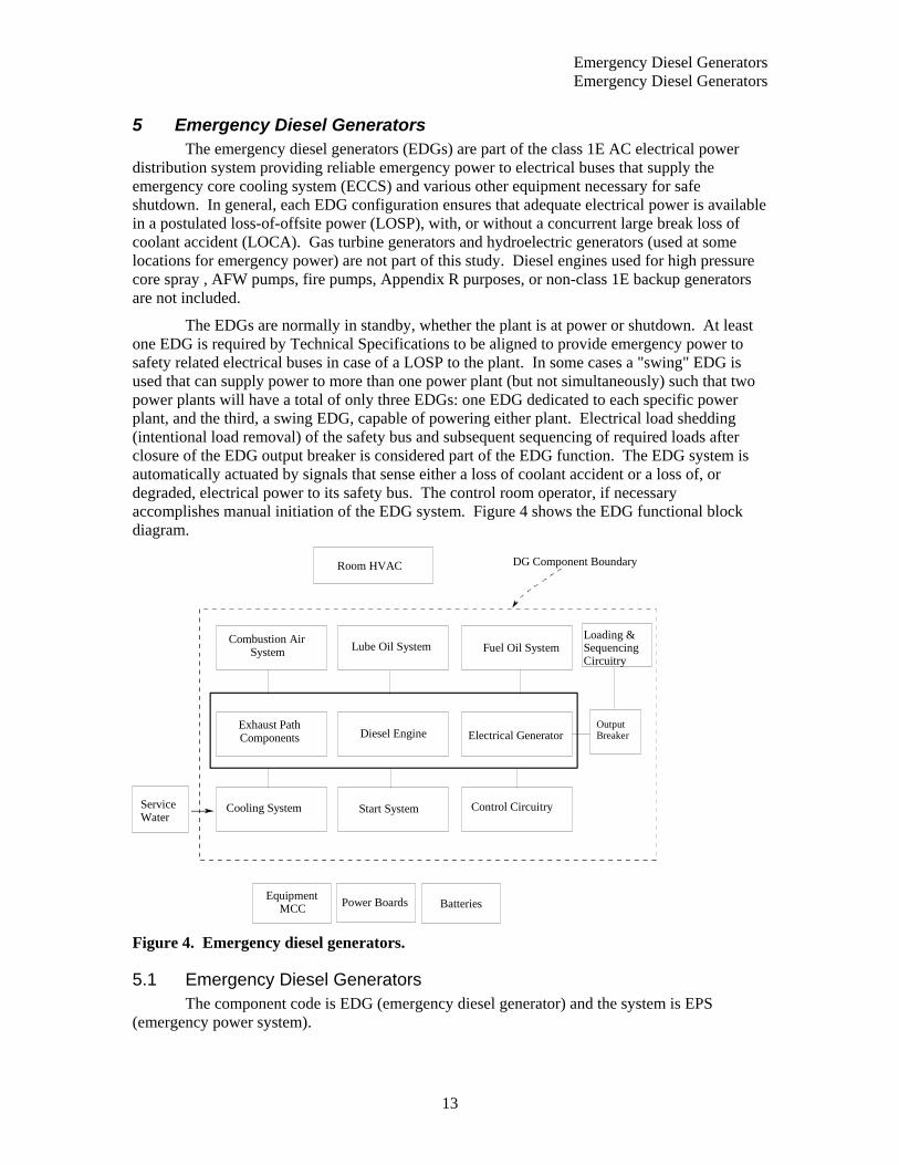
5 Emergency Diesel Generators The emergency diesel generators (EDGs) are part of the class 1E AC electrical power distribution system providing reliable emergency power to electrical buses that supply the emergency core cooling system (ECCS) and various other equipment necessary for safe shutdown. In general, each EDG configuration ensures that adequate electrical power is available in a postulated loss-of-offsite power (LOSP), with, or without a concurrent large break loss of coolant accident (LOCA). Gas turbine generators and hydroelectric generators (used at some locations for emergency power) are not part of this study. Diesel engines used for high pressure core spray , AFW pumps, fire pumps, Appendix R purposes, or non-class 1E backup generators are not included.
The EDGs are normally in standby, whether the plant is at power or shutdown. At least one EDG is required by Technical Specifications to be aligned to provide emergency power to safety related electrical buses in case of a LOSP to the plant. In some cases a "swing" EDG is used that can supply power to more than one power plant (but not simultaneously) such that two power plants will have a total of only three EDGs: one EDG dedicated to each specific power plant, and the third, a swing EDG, capable of powering either plant. Electrical load shedding (intentional load removal) of the safety bus and subsequent sequencing of required loads after closure of the EDG output breaker is considered part of the EDG function. The EDG system is automatically actuated by signals that sense either a loss of coolant accident or a loss of, or degraded, electrical power to its safety bus. The control room operator, if necessary accomplishes manual initiation of the EDG system. Figure 4 shows the EDG functional block diagram.
Cooling System Start System Control Circuitry
EquipmentMCC Power Boards Batteries
Exhaust PathComponents Diesel Engine Electrical Generator
Combustion AirSystem Lube Oil System Fuel Oil System
OutputBreaker
Loading &SequencingCircuitry
DG Component BoundaryRoom HVAC
ServiceWater
Figure 4. Emergency diesel generators.
5.1 Emergency Diesel Generators The component code is EDG (emergency diesel generator) and the system is EPS
(emergency power system).

Emergency Diesel Generators Emergency Diesel Generators
14
5.1.1 Emergency Diesel Generators Component Boundaries The super component, EDG, is defined as the combination of the diesel engine(s) with all components in the exhaust path, electrical generator, generator exciter, output breaker, combustion air, lube oil systems (including the device that physically controls the cooling medium), cooling system (including the device that physically controls the cooling medium), fuel oil system (including all storage tanks permanently connected to the engine supply), and the starting compressed air system. All pumps, valves, and valve operators with their power supply breakers, and associated piping for the above systems are included. The only portions of the EDG cooling systems included are the specific devices that control cooling medium flow to the individual EDG auxiliary heat exchangers, including the control instruments. The service water system (cooling medium) outside the control valves was excluded. Figure 4 shows the component boundary as defined for this study.
Included within the EDG system are the circuit breakers that are located at the motor control centers (MCC) and the associated power boards that supply power specifically to any of the EDG equipment. The MCCs and the power boards are not included except the load shedding and load sequencing circuitry/devices that are, in some cases, physically located within the MCCs. Load shedding of the safety bus and subsequent load sequencing onto the bus of vital electrical loads is considered integral to the EDG function and is therefore considered within the bounds of this study. All instrumentation, control logic, and the attendant process detectors for system initiations, trips, and operational control are included. Batteries are included if failures impacted EDG functional operability.
5.1.2 Emergency Diesel Generators Failure Event Definition Successful EDG system response to a demand requires that the EDGs provide electrical power to the safety bus with all required loads energized (sequenced onto the bus) for the duration of the mission time. The failure modes used in evaluating the EDG data are:
FS Fail to Start A successful start will be the EDG start through output breaker closing and loading to the requirement for the current configuration. For example, if the start is in response to an actual loss of power, the full sequence of loading must be completed in order for the start to be considered successful. If only partial loading occurs before the failure, the failure mode will be fail to start. If the start requires no loading (e.g. a test or on a SI signal), the success criteria will be only the EDG start.
FR Fail to Run In order for the failure to be a failure to run, the EDG must be loaded (required for the current conditions) and stable before the failure. This failure mode implies a successful start, but a subsequent failure to run for the duration of the mission time.
FX Fail to Stop The component fails to stop operating.
The EDG failures represent malfunctions that hindered or prevented successful operation of the EDG system. Slow EDG starting times during testing, are considered successful provided the start took less than 20 seconds and the EDG was otherwise fully capable. Most licensees reporting a slow start time provided additional analysis to indicate that the slow start time did not adversely affect the ability of the plant to respond to a design basis accident.
For purposes of this CCF study, a personnel error resulting in more than one functionally inoperable EDG (even without any component malfunction) was considered a CCF failure. Examples are improper prestart lineup and significant setting errors in the governor or voltage
Emergency Diesel Generators Emergency Diesel Generators
15
regulator controls. These types of errors would have prevented fulfillment of the EDG system design function. On the other hand, operator error in such things as paralleling to the grid or improper adjustment of voltage or speed controls are not considered failures because these do not normally apply to an actual EDG demand unless the improper synchronization or loading resulted in failed piece-parts.
Emergency Diesel Generators Emergency Diesel Generators
16
PWR Containment Spray Emergency Diesel Generators
17
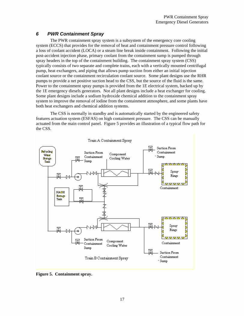
6 PWR Containment Spray The PWR containment spray system is a subsystem of the emergency core cooling system (ECCS) that provides for the removal of heat and containment pressure control following a loss of coolant accident (LOCA) or a steam line break inside containment. Following the initial post-accident injection phase, primary coolant from the containment sump is pumped through spray headers in the top of the containment building. The containment spray system (CSS) typically consists of two separate and complete trains, each with a vertically mounted centrifugal pump, heat exchangers, and piping that allows pump suction from either an initial injection coolant source or the containment recirculation coolant source. Some plant designs use the RHR pumps to provide a net positive suction head to the CSS, but the source of the fluid is the same. Power to the containment spray pumps is provided from the 1E electrical system, backed up by the 1E emergency diesels generators. Not all plant designs include a heat exchanger for cooling. Some plant designs include a sodium hydroxide chemical addition to the containment spray system to improve the removal of iodine from the containment atmosphere, and some plants have both heat exchangers and chemical addition systems.
The CSS is normally in standby and is automatically started by the engineered safety features actuation system (ESFAS) on high containment pressure. The CSS can be manually actuated from the main control panel. Figure 5 provides an illustration of a typical flow path for the CSS.
Figure 5. Containment spray.

PWR Containment Spray PWR Containment Spray Motor Operated Valves
18
6.1 Containment Spray Heat Exchanger The component code is HTX (heat exchanger) and the system is CSS (containment spray
system).
6.1.1 Containment Spray Heat Exchanger Component Boundaries The main component of a CSS heat exchanger is the heat exchanger itself. It consists of the main tank (shell), internal cooling water tubes, temperature sensors, and a temperature control valve. The cooling water system on the heat exchanger side of the isolation valves in included; the remainder of the cooling water system is not.
6.1.2 Containment Spray Heat Exchanger Failure Event Definition Successful operation of a containment spray heat exchanger is defined as heat transfer above the minimum design basis requirements. The only failure mode used in evaluating CSS heat exchanger data is:
PG Plugged or Failure to Transfer Heat.
Examples are reduction in flow affecting heat transfer rate and temperature switch failure, and biological fouling.
Failures that occurred during testing are included with the failures that occurred during plant transients requiring operation of the CSR heat exchangers.
6.2 PWR Containment Spray Motor Operated Valves The component code is MOV (motor operated valve) and the system is CSS (containment
spray system).
6.2.1 PWR Containment Spray Motor Operated Valve Component Boundaries
The main components of a motor operated valve are the valve, including its internal piece-part components (e.g. gate, stem), and the actuator. The operator includes the circuit breaker, power leads, sensors (flow, pressure, and level), and motor as piece parts. Only sensors unique to the operation of the individual valve are included with the valve for CCF analysis. All MOVs have manual hand wheels, and can be manually operated. AC or DC power is required for valve operation.
The MOVs in the containment spray system are used in the following applications:
• admitting borated water to the containment spray system from the RWST ,
• shifting suction of the containment spray pumps from the RWST to the containment sump,
• admitting chemical addition to the containment spray, and
• admitting coolant to the containment spray rings.
6.2.2 PWR Containment Spray Motor Operated Valve Failure Event Definition
The function of the containment spray MOVs is to allow borated water flow to the containment spray system spray rings. Some valves serve as a system containment boundary and would need to close to isolate leaks. The failure modes used in evaluating the containment spray system MOV data are:

PWR Containment Spray PWR Containment Spray Pumps
19
CC Fail to Open The valve must be in the fully open position. Anything less than full open is considered a failure to open.
OO Fail to Close The valve must be fully closed on a close signal, or it is considered a failure to close.
VR Failure to Remain Closed In cases where the motor operated valve has been closed for a substantial period and is then discovered leaking, the failure will be coded as VR. If the discovery is made soon after a system configuration change (i.e., pump operation), then the failure is coded as OO.
A stroke time testing failure is not considered a failure if the valve reached the required open or closed state and no failed piece-parts are reported. Generally, slow stroke times that are not due to a failed piece-part are adjusted and then the valve passes. These are not to be coded as failures. However, if degradation of valve internals was reported and piece-parts are replaced, then the event will be recorded as a failure in the direction of the test and assigned an appropriate degradation value.
Valve failures include functional inoperabilities due to reasons not related to valve hardware malfunctions. Examples are breaker de-energized and locked open (human error), and system conditions (abnormal pressure and temperature) that prevent operation. Failure of the electrical operator without coincident failure of the manual operator is considered a failure. These events are considered individually to determine if the failure occurred within the component boundary, or if the failure was due to external factors such that the event was not a CCF event.
Failures of the operator and circuit breaker are evaluated to determine the ultimate effect on valve operability for assignment of failure mode. For example, a circuit breaker may fail to close, but the resulting effect on the valve is failure to open, so the valve failure mode is "CC."
6.3 PWR Containment Spray Pumps The component code is MDP (motor driven pump) and the system is CSS (containment
spray system).
6.3.1 PWR Containment Spray Pump Component Boundaries The main component of a containment spray pump is the pump itself. This component is normally in standby and is started by sensors actuating the circuit breaker to the driver, which will in turn operate the pump. These pumps can also be started up manually via remote control switches. Stopping of the pump is accomplished only by operator actions via the control switches or automatic signals designed to protect the pumps or motors (e.g., overcurrent).
The boundaries include the pump itself, the motor including the circuit breaker, lubrication or cooling systems, and any sensors, controls, or indication required for operation of the pump. Sensors or input logic that affect components other than a single containment spray pump are not included in the component boundaries.
6.3.2 PWR Containment Spray Pump Failure Event Definition Successful operation of a containment spray pump is defined for two distinct modes of operation. If the system is in the normal standby condition, it must respond to an actuation signal by starting, which consists of obtaining design discharge pressure and flow. Once running, the containment spray pump must continue to produce design flow and discharge pressure until its
PWR Containment Spray PWR Containment Sump Strainers
20
service is no longer needed. The respective failure modes used for evaluating the containment spray pump data are:
FS Failure to Start Examples are: circuit breaker fails to close, pump fails to achieve design flow or pressure, control switch failure, and flow-switch failure.
FR Failure to Run Examples are: excessive bearing vibration, cavitation, decreasing performance (less than design flow or pressure) while running, excessive packing leaks, and loss of lubrication/cooling.
FX Fail to Stop The component fails to stop operating.
Containment spray pump malfunctions are considered failures to start or failures to run. The pump is considered to fail the start portion of its mission if it fails to reach rated flow and pressure. Once rated flow and pressure have been demonstrated, and a failure is observed, the pump will be considered to have failed its run mission. Testing that demonstrates desired bypass flow will be considered to be a successful start. Pump failures include those failures that are caused by power supply breakers or sensors that are unique to the pump-driver combination. Failures that occurred during testing are included with the failures that occurred during plant transients requiring operation of the containment spray pumps.
Pump motor failures are evaluated to determine the effect on pump operability. In general, if the failure causes the pump to fail to operate, it will be considered a failure. Failures of the sensors or control circuitry to provide input in other systems (e.g., interlocks or indication) will not be considered pump failures.
6.4 PWR Containment Sump Strainers The containment sump strainers are stationary screens in the emergency core cooling
system (ECCS) that function to protect the ECCS pumps and prevent plugging of containment spray nozzles from debris that may be in containment when the sump is used as a coolant source. The containment is used a suction source for the containment recirculation spray pumps, the low pressure safety injection pumps, and the high pressure safety injection pumps.
The sump screen assembly is divided into two or more sections to prevent damage and large debris on one side from affecting the other side. Typically the sump strainers are a combination of a heavy grate (to keep out large debris) and smaller mesh strainers to strain out small debris such as insulation fibers. The containment sump strainers do not have any moving parts or electrical connections.
The component code is STR (strainer) and the system is CSS (containment spray system).
6.4.1 PWR Containment Sump Strainer Component Boundaries The containment sump strainer includes the strainer screens used to filter debris and the sump area that serves to accumulate coolant for ECCS pumps suction.
6.4.2 PWR Containment Sump Strainer Failure Event Definition Successful operation of the containment sump strainer is allowing flow from the sump to the pumps. The only failure mode used for evaluating the sump strainer data is:
PG Plugged, or Failure to Allow Flow
Examples are: physical damage (to screens) that reduces flow cross-section, and accumulation of debris in sump.
PWR Containment Spray PWR Containment Sump Strainers
21

BWR Residual Heat Removal (Low Pressure Coolant Injection) PWR Containment Sump Strainers
23
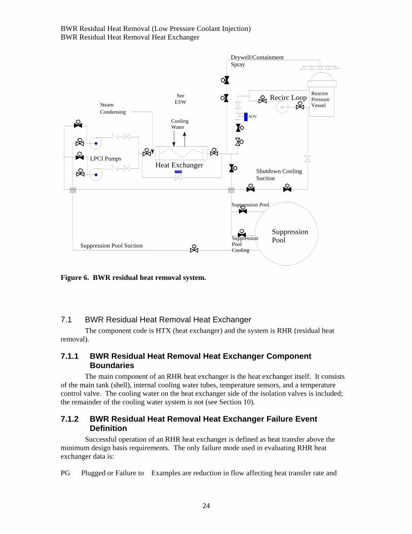
7 BWR Residual Heat Removal (Low Pressure Coolant Injection) The residual heat removal (RHR) system is a subsystem of the emergency core cooling system (ECCS) that functions to provide decay heat removal/shutdown cooling to maintain reactor coolant inventory and provide adequate long term decay heat removal following an emergency plant shutdown. The RHR function is performed over a relatively long time interval after shutdown. The RHR system injects directly into the primary system through the heat exchangers. Figure 6 illustrates the typical flow path for the RHR system. The system is typically comprised of two separate trains, each train with two high capacity centrifugal pumps, heat exchangers, connecting piping, and valves to control flow, etc. The pumps receive power from the 1E emergency power system, which is backed up by the emergency diesel generators.
The system is normally aligned and in the standby mode during plant operation. The RHR pumps are started by the engineered safety features actuation system (ESFAS) or may be manually actuated from the main control room.
The RHR system serves several functions by operating in different modes:
• Low pressure coolant injection (LPCI) mode - to provide low pressure makeup water to the reactor vessel for core cooling under loss of coolant accident (LOCA) conditions,
• Containment spray mode - to reduce primary containment pressure and temperature following a LOCA
• Suppression pool cooling mode - to remove heat from the suppression pool, and
• Shutdown cooling mode – to remove heat from the reactor vessel. Shutdown cooling is a mode of the RHR system or a specific separate (non-safety-related) system in early BWR designs.
Under accident conditions, the LPCI mode is automatically initiated. All other modes require manual system alignment for proper operation. The LPCI mode takes suction from the suppression pool and discharges to the reactor vessel penetrations. The RHR heat exchangers are bypassed in this mode. The containment spray mode protects the containment structure from possible over pressurization from steam, which might bypass the suppression pool, including system breaks within the containment volume. In this mode, water is pumped from the suppression pool through heat exchangers to spray nozzles located high in the containment space. The suppression pool-cooling mode is designed to limit the long-term bulk temperature rise of the suppression pool water following a design basis LOCA or safety and relief valve (SRV) actuation following an overpressure transient. A closed path from the suppression pool through the RHR loops to the reactor vessel and back to the suppression pool through the break can be maintained for long-term decay heat removal from the core.
Note that BWR-1, -2 and early –3 plant designs have separate dedicated shutdown cooling systems. BWR-2 designs do not have an LPCI system (feedwater injection systems instead).
BWR Residual Heat Removal (Low Pressure Coolant Injection) BWR Residual Heat Removal Heat Exchanger
24
CoolingWater
Suppression Pool Suction
Shutdown Cooling Suction
Recirc Loop
Suppression Pool
LPCI Pumps
Drywell/ContainmentSpray
Heat Exchanger
Steam Condensing
AOV
Suppression Pool S
SuppressionPoolCooling
Reactor Pressure Vessel
See ESW
Figure 6. BWR residual heat removal system.
7.1 BWR Residual Heat Removal Heat Exchanger The component code is HTX (heat exchanger) and the system is RHR (residual heat
removal).
7.1.1 BWR Residual Heat Removal Heat Exchanger Component Boundaries
The main component of an RHR heat exchanger is the heat exchanger itself. It consists of the main tank (shell), internal cooling water tubes, temperature sensors, and a temperature control valve. The cooling water on the heat exchanger side of the isolation valves is included; the remainder of the cooling water system is not (see Section 10).
7.1.2 BWR Residual Heat Removal Heat Exchanger Failure Event Definition
Successful operation of an RHR heat exchanger is defined as heat transfer above the minimum design basis requirements. The only failure mode used in evaluating RHR heat exchanger data is:
PG Plugged or Failure to Examples are reduction in flow affecting heat transfer rate and
BWR Residual Heat Removal (Low Pressure Coolant Injection) BWR Residual Heat Removal Motor-Operated Valves
25
Transfer Heat. temperature switch failure, and biological fouling.
7.2 BWR Residual Heat Removal Pumps The component code is MDP (motor driven pump) and the system is RHR (residual heat
removal).
7.2.1 BWR Residual Heat Removal Pump Component Boundaries The main component of a RHR pump is the pump itself. This component is normally in standby and is started by sensors actuating the circuit breaker to the driver, which will in turn operate the pump. These pumps can also be started up manually via remote control switches. Stopping of the pump is accomplished only by operator actions via the control switches or automatic signals designed to protect the pumps or motors (e.g., overcurrent).
The boundaries include the pump itself, the motor including the circuit breaker, lubrication or cooling systems, and any sensors, controls, or indication required for operation of the pump. Sensors or input logic that affect components other than a single LPCI pump are not included in the component boundaries.
7.2.2 BWR Residual Heat Removal Pump Failure Event Definition Successful operation of a RHR pump is defined for two distinct modes of operation. If the system is in the normal standby condition, it must respond to an actuation signal by starting which consists of obtaining design discharge pressure and flow. Once running, the RHR pump must continue to produce design flow and discharge pressure until its service is no longer needed. The respective failure modes used for evaluating the RHR pump data are:
FS Failure to Start Examples are: circuit breaker fails to close, pump fails to achieve design flow or pressure, control switch failure, and flow-switch failure.
FR Failure to Run Examples are: excessive bearing vibration, cavitation, decreasing performance (less than design flow or pressure) while running, excessive packing leaks, and loss of lubrication/cooling.
FX Fail to Stop The component fails to stop operating.
RHR pump malfunctions are considered failures to start or failures to run. The pump is considered to fail the start portion of its mission if it fails to reach rated flow and pressure. Once rated flow and pressure have been demonstrated, and a failure is observed, the pump will be considered to have failed its run mission. Testing that demonstrates desired bypass flow will be considered to be a successful start. Pump failures include those failures that are caused by power supply breakers or sensors that are unique to the pump-driver combination. Failures that occurred during testing are included with the failures that occurred during plant transients requiring operation of the RHR pumps.
Pump motor failures are evaluated to determine the effect on pump operability. In general, if the failure causes the pump to fail to operate, it will be considered a failure. Failures of the sensors or control circuitry to provide input in other systems (e.g., interlocks or indication) will not be considered pump failures.
7.3 BWR Residual Heat Removal Motor-Operated Valves The component code is MOV (motor operated valve) and the system is RHR (residual
heat removal).
BWR Residual Heat Removal (Low Pressure Coolant Injection) BWR Residual Heat Removal Motor-Operated Valves
26
7.3.1 BWR Residual Heat Removal Motor-Operated Valve Component Boundaries
The main components of a motor-operated valve are the valve, including its internal piece-part components (e.g. gate, stem), and the operator. The operator includes the circuit breaker, power leads, sensors (flow, pressure, and level), and motor as piece parts. Only sensors unique to the operation of the individual valve are included with the valve for CCF analysis. All MOVs have manual hand wheels, and can be manually operated. AC or DC power is required for valve operation.
MOVs are used in the RHR system in the following applications:
• Pump discharge,
• Pump suction,
• Loop injection, and
• System inter- or cross-connection.
7.3.2 BWR Residual Heat Removal Motor-Operated Valve Failure Event Definition
The function of the injection MOVs is to allow injection flow to the reactor vessel. During normal plant operations, most of the MOVs remain closed to isolate the high pressure and low-pressure portions of the system. The failure modes used in evaluating the RHR MOV data are:
CC Fail to Open The valve must be in the fully open position. Anything less than full open is considered a failure to open.
OO Fail to Close The valve must be fully closed on a close signal, or it is considered a failure to close.
VR Failure to Remain Closed In cases where the motor operated valve has been closed for a substantial period and is then discovered leaking, the failure will be coded as VR. If the discovery is made soon after a system configuration change (i.e., pump operation), then the failure is coded as OO.
A stroke time testing failure is not considered a failure if the valve reached the required open or closed state and no failed piece-parts are reported. Generally, slow stroke times that are not due to a failed piece-part are adjusted and then the valve passes. These are not to be coded as failures. However, if degradation of valve internals was reported and piece-parts are replaced, then the event will be recorded as a failure in the direction of the test and assigned an appropriate degradation value.
Valve failures include functional inoperabilities due to reasons not related to valve hardware malfunctions. Examples are breaker de-energized and locked open (human error), and system conditions (abnormal pressure and temperature) that prevent operation. Failure of the electrical operator without coincident failure of the manual operator is considered a failure. These events are considered individually to determine if the failure occurred within the component boundary, or if the failure was due to external factors such that the event was not a CCF event.

BWR Residual Heat Removal (Low Pressure Coolant Injection) BWR Suppression Pool Strainer
27
Failures of the operator and circuit breaker are evaluated to determine the ultimate effect on valve operability for assignment of failure mode. For example, a circuit breaker may fail to close, but the resulting effect on the valve is failure to open, so the failure mode is "CC."
7.4 BWR Residual Heat Removal Check Valves The component code is CKV (check valve) or CKS (stop check valve) and the system is
RHR (residual heat removal).
7.4.1 BWR Residual Heat Removal Check Valve Component Boundaries The main component of a check valve is the valve itself. This component is operated by system pressure overcoming gravity. Typically, there is no capability to manual open, close, or isolate these valves, however, some check valves have manual hand wheels on them (stop-check) and can be manually closed. This should not affect component operation and in some cases the air supply is turned off during operation as a precaution. No power is required for valve operation. Check valves are installed in RHR systems in the following areas:
• Pump discharge,
• Suppression pool suction, and
• Loop injection.
The function of the check valve is to form a conditional boundary (i.e., one direction) between high pressure and low-pressure sections of a system during static conditions. By design, the valve will open to allow flow when the low-pressure section has experienced a pressure increase (e.g., pump start). For the purposes of this study, the boundaries will encompass the valve body including internals (e.g. disk, spring), and operators in the cases of air assisted check valves.
7.4.2 BWR Residual Heat Removal Check Valve Failure Event Definition Check valve malfunctions are considered failures to open or close on demand and failure to stay closed which includes excessive leakage through the valve. Failure modes used to analyze check valve data are:
CC Failure to Open Examples are: Check valve sticks closed, check valve partially opens.
OO Failure to Close Examples are: Check valve doesn’t fully close and failure to re-seat.
VR Failure to Remain Closed
In cases where the check valve has been closed for a substantial period and is then discovered leaking the failure will be coded as VR.
RHR check valve failures that occurred during testing are included with the failures that occurred during plant transients requiring operation of the RHR check valves.
7.5 BWR Suppression Pool Strainer The suppression pool strainers are stationary screens in the emergency core cooling
system (ECCS) that function to protect the ECCS pumps. The suppression pool is used a suction source for the RHR pumps, the low pressure core spray, the reactor core isolation cooling, and the high-pressure coolant injection pumps.

BWR Residual Heat Removal (Low Pressure Coolant Injection) BWR Suppression Pool Strainer
28
The sump screen assembly is separated into two or more sections to prevent damage and large debris on one side from affecting the other side. Typically, the sump strainers are a combination of a heavy grate (to keep out large debris) and smaller mesh strainers to strain out small debris such as insulation fibers. The suppression pool strainers do not have any moving parts or electrical connections.
The component code is STR (strainer) and the system is RHR (residual heat removal).
7.5.1 BWR Suppression Pool Strainer Component Boundaries The main component of a sump strainer is the strainer itself. This component is normally in a standby mode and is a passive component with no moving parts.
7.5.2 BWR Suppression Pool Strainer Failure Event Definition Successful operation of the containment sump strainer is allowing flow from the sump to the pumps. The only failure mode used for evaluating the sump strainer data is:
PG Plugged, or Failure to Allow Flow
Examples are: physical damage (to screens) that reduces flow cross-section, and accumulation of debris in sump.
BWR Isolation Condenser System BWR Isolation Condenser Heat Exchanger
29
8 BWR Isolation Condenser System The isolation condenser (ISO) is part of the BWR emergency core cooling system (ECCS) that transfers residual and decay heat from the reactor coolant system to the atmosphere in the event that the main condenser is not available, or when a high reactor pressure condition exists (BWR-2 and –3 plants only). The ISO system may be placed into service either manually or automatically. The ISO system operates using natural circulation as the driving head through the isolation condenser tubes, and is available for operation when there is no electrical power. The primary side of the isolation condenser system is a closed loop from the reactor pressure vessel steam space through the tubes in the isolation condenser, with the condensate returning to the recirculation loops. During normal plant operations, the secondary (shell) side of the isolation condenser contains sufficient water to cover the primary side tubes. The water in the shell side transfers the heat from the primary side by boiling off and venting directly to the atmosphere. Makeup to the secondary side is provided through the fire water system or through an alternate makeup source, such as the condensate transfer system.
Only five BWR plants have an ISO system; those that don’t, have the ISO have reactor core isolation cooling, which is a pump driven system. (The only remaining plants with an isolation condenser system are Dresden 2&3, Nine Mile Point 1, and Oyster Creek). Some plants have two ICs, and other plants have one IC that contains two sets of steam cooling tubes. (Nine Mile Point 1 has four isolation condensers). Figure 7 shows a typical isolation condenser system.
Recirc Pump
ReactorVessel
Vent to Atmosphere
To ShutdownCoolingPumps
Makeup from Condensate Transfer Pumps
Makeup fromFire Protection
IsolationCondenser
A O V
Vent to Main Steam Line
Figure 7. BWR isolation condenser.
8.1 BWR Isolation Condenser Heat Exchanger The isolation condenser heat exchanger is a tube and shell type of heat exchanger. The
tube side carries the reactor coolant when the valves are opened. The shell side contains condensate, which is boiled off to atmosphere. The component code is HTX (heat exchanger) and the system is ISO (isolation condenser).

BWR Isolation Condenser System BWR Isolation Condenser Air-Operated Valves
30
8.1.1 BWR Isolation Condenser Heat Exchanger Component Boundaries The main components of a condenser are the tubes, tube sheets, and shell.
8.1.2 BWR Isolation Condenser Heat Exchanger Failure Event Definition The function of the isolation condenser is to provide an alternate decay heat removal path, separate from the other systems within the ECCS. The PRA mission for the isolation condenser system is to provide water for heat transfer for the removal of decay heat from the reactor coolant system. Failure of the isolation condenser system is defined as any condition that does not permit either the steam flow from the reactor pressure vessel, or condensate water return to the reactor coolant system (RCS) or makeup water flow to the IC shell flow from the makeup sources.
Only one failure mode was used in evaluating the isolation condenser data:
PG Plugged or Failure to Transfer Heat.
Examples are reduction in flow affecting heat transfer rate and temperature switch failure, and biological fouling.
If the failure of the ISO heat exchanger to perform its heat transfer function is due to a valve failure, the failure would be recorded as a valve failure. If, however, the ISO failure was due to human action that misaligned a valve, the failure was recorded as a failure of the ISO.
8.2 BWR Isolation Condenser Air-Operated Valves The component code is AOV (air operated valve) and the system is ISO (isolation
condenser).
8.2.1 BWR Isolation Condenser Air-Operated Valve Component Boundaries
The main components of an air-operated valve are the valve, including its internal piece-part components (e.g. disk, seat, stem, packing), and the operator. The operator includes the internal air operator piece-parts, the air supply lines specific to the AOV, sensors, solenoids to control the air supply, and the power leads to these solenoids as piece-parts. Only sensors unique to the operation of the individual valve are included with the valve for CCF analysis. Some AOVs have manual hand wheels, and can be manually operated or blocked. AC or DC power is required for solenoid and sensor operation.
The AOVs in the isolation condenser system are used to control condensing water flow to the isolation condenser and to provide a vent path from the steam inlet line to a main steam line during standby conditions.
8.2.2 BWR Isolation Condenser Air-Operated Valve Failure Event Definition
The function of the isolation condenser AOVs is to control makeup flow to the IC shell from the CST and to vent the steam inlet line. The event boundary for the isolation condenser system AOVs is defined as any condition that does not permit control of the makeup flow to the IC shell or prevents venting the steam inlet line.
The failure modes used in evaluating the isolation condenser AOV data are:
CC Fail to Open The valve must be in the fully open position. Anything less than full open is considered a failure to open.

BWR Isolation Condenser System BWR Isolation Condenser Motor-Operated Valves
31
OO Fail to Close The valve must be fully closed on a close signal, or it is considered a failure to close.
VR Failure to Remain Closed In cases where the motor operated valve has been closed for a substantial period and is then discovered leaking, the failure will be coded as VR. If the discovery is made soon after a system configuration change (i.e., pump operation), then the failure is coded as OO.
A stroke time testing failure is not considered a failure if the valve reached the required open or closed state and no failed piece-parts are reported. Generally, slow stroke times that are not due to a failed piece-part are adjusted and then the valve passes. These are not to be coded as failures. However, if degradation of valve internals was reported and piece-parts are replaced, then the event will be recorded as a failure in the direction of the test and assigned an appropriate degradation value.
Valve failures include functional inoperabilities due to reasons not related to valve hardware malfunctions. Examples are loss of instrument air to the valve operator, control power de-energized, and system conditions (abnormal pressure and temperature) that prevent operation. Failure of the pneumatic operator without coincident failure of the manual operator is considered as a failure. These events are considered individually to determine of the failure occurred within the component boundary, or if the failure was due to external factors such that the event was not a CCF event.
Failures of the operator are evaluated to determine the ultimate effect on valve operability for assignment of failure mode. For example, a loss of instrument air to the operator may cause the valve to cycle to its fail-safe position, but the resulting effect on the valve is failure to reposition so the failure mode is failure to operate to that position (if it is readily discernable, otherwise a failure of “CC” is assigned.)
8.3 BWR Isolation Condenser Motor-Operated Valves The component code is MOV (motor operated valve) and the system is ISO (isolation
condenser).
8.3.1 BWR Isolation Condenser Motor-Operated Valve Component Boundaries
The main components of a motor-operated valve are the valve, including its internal piece-part components (e.g. gate, stem), and the operator. The operator includes the circuit breaker, power leads, sensors (flow, pressure, and level), and motor as piece parts. Only sensors unique to the operation of the individual valve are included with the valve for CCF analysis. All MOVs have manual hand wheels, and can be manually operated. AC or DC power is required for valve operation.
The MOVs in the isolation condenser system are used in the following applications:
• Admitting steam to the isolation condenser from the main steam line,
• Supplying condensate from the isolation condenser back to the feedwater line) and
• Supplying cooling water to the isolation condenser from either the condensate system or the fire water system.
BWR Isolation Condenser System BWR Isolation Condenser Motor-Operated Valves
32
8.3.2 BWR Isolation Condenser Motor-Operated Valve Failure Event Definition
The function of the primary side MOVs is to allow primary coolant flow to the isolation condenser. The function of the secondary side MOV is to allow condensing medium makeup flow into the isolation condenser shell. All valves serve as a system containment boundary and would need to close to isolate leaks. The failure modes used in evaluating the isolation condenser MOV data are:
CC Fail to Open The valve must be in the fully open position. Anything less than full open is considered a failure to open.
OO Fail to Close The valve must be fully closed on a close signal, or it is considered a failure to close.
VR Failure to Remain Closed In cases where the motor operated valve has been closed for a substantial period and is then discovered leaking, the failure will be coded as VR. If the discovery is made soon after a system configuration change (i.e., pump operation), then the failure is coded as OO.
A stroke time testing failure is not considered a failure if the valve reached the required open or closed state and no failed piece-parts are reported. Generally, slow stroke times that are not due to a failed piece-part are adjusted and then the valve passes. These are not to be coded as failures. However, if degradation of valve internals was reported and piece-parts are replaced, then the event will be recorded as a failure in the direction of the test and assigned an appropriate degradation value.
Valve failures include functional inoperabilities due to reasons not related to valve hardware malfunctions. Examples are breaker de-energized and locked open (human error), and system conditions (abnormal pressure and temperature) that prevent operation. Failure of the electrical operator without coincident failure of the manual operator is considered a failure.
These events are considered individually to determine if the failure occurred within the component boundary, or if the failure was due to external factors such that the event was not a CCF event.
Failures of the operator and circuit breaker are evaluated to determine the ultimate effect on valve operability for assignment of failure mode. For example, a circuit breaker may fail to close, but the resulting effect on the valve is failure to open, so the failure mode is "CC".

PWR Auxiliary Feedwater BWR Isolation Condenser Motor-Operated Valves
33
9 PWR Auxiliary Feedwater The auxiliary feedwater system provides a source of feedwater to the steam generators to remove decay heat from the reactor coolant system (RCS) when: (a) the main feedwater system is not available, and (b) RCS pressure is too high to permit heat removal by the residual heat removal (RHR) system. The AFW system is comprised of two, three, or four trains, each with an auxiliary feedwater pump, including the associated pump driver. The combinations of pump-driver sets range from all motor-driven to all turbine-driven AFW pumps and, in a few cases, diesel-driven pumps. Most of the designs incorporate a combination of two full capacity motor-driven and one double capacity turbine-driven pump. There are no plants with more than one diesel-driven auxiliary feedwater pump, so CCF analysis of diesel-driven pumps is not applicable. The motor-driven pumps are supplied power from the IE class power system with backup power available from the IE emergency diesel generators (EDG). The water supply for the system is from the condensate storage tank (CST) with a backup source of water (untreated) available from the service water system.
The AFW system is normally in standby. The motor-driven pumps start on one of the following conditions: a safety injection (SI) signal, a low-low level in any steam generator, loss of both main feedwater pumps (MFP), a loss of off-site power (LOSP) or manual initiation. The turbine-driven pump will start on either a low-low level in more than one steam generator or a loss of off-site power. Feedwater flow to the steam generators is controlled from the main control room by air, motor, or hydraulically operated valves. Motor-driven pump run out is controlled by an air or hydraulically controlled regulator valve on the pump discharge. The turbine-driven pump steam supply is controlled by air or hydraulically operated valves. Although not an original design function, the AFW system is commonly used for feedwater supply during startup and low power operations (<15% power). Figure 8 shows a typical auxiliary feedwater system.
Emerg ServWaterSupply
AO V
AO V
Turbine
CondensateStorageTank
Main Feedwater
Main Feedwater
Main Feedwater
SteamSupply
Flow Control Valve
Flow Control Valve
Flow Control Valves
AO VAO V
AO V
AO V
AO V
AO V
AO V
AO V
Flow Control Valve
MOV
MOV
MOV
MOV
MOV
MOV
PressureControlValve
PressureControlValve
GeneratorSteam
SteamGenerator
SteamGenerator
Figure 8. Auxiliary feedwater system.
PWR Auxiliary Feedwater Auxiliary Feedwater Pump
34
9.1 Auxiliary Feedwater Pump The component code is MDP (motor driven pump), TDP (turbine driven pump), or DDP
(diesel driven pump) and the system is AFW (auxiliary feedwater). In special cases where the CCF between pumps applies to more than one type of driver, the CCF will be coded as a PMP (general pump) component and the individual events are coded as the applicable component type.
9.1.1 Auxiliary Feedwater Pump Component Boundaries The main components of an AFW pump are the pump and pump driver. The AFP is normally in standby and is started by sensors actuating the circuit breaker or steam supply valve to the driver, which will in turn operate the pump. These pumps can also be started manually via remote control switches. Stopping of the pump is accomplished by operator actions via the control switches or automatic signals designed to protect the pumps or drivers (e.g., overcurrent, overspeed).
The boundaries include the pump itself, the turbine or motor, including governor control or circuit breaker as applicable, lubrication or cooling systems, and any sensors, controls, or indication required for operation of the pump. Only controls and sensors unique to the operation of the individual pump are included in the pump boundary for CCF analysis.
9.1.2 Auxiliary Feedwater Pump Failure Event Definition Successful operation of an AFW pump is comprised of two distinct modes of operation. If the AFW system is in the normal standby condition, it must respond to an actuation signal by starting and obtaining design discharge pressure or flow. Once running, the AFW pump must continue to produce design flow or discharge pressure until its service is no longer needed (for the PRA mission time). The respective failure modes used for evaluating the AFP data are:
FS Failure to Start Examples are: circuit breaker fails to close, pump fails to achieve design flow or pressure, control switch failure, and flow-switch failure.
FR Failure to Run Examples are: excessive bearing vibration, cavitation, decreasing performance (less than design flow or pressure) while running, excessive packing leaks, and loss of lubrication/cooling.
FX Fail to Stop The component fails to stop operating.
AFW pump malfunctions are considered failures to start and failure to run. The pump is considered to fail the start portion of its mission if it fails to reach rated flow and pressure. Once rated flow and pressure have been demonstrated, and a failure is observed, the pump will be considered to have failed its run mission. Testing that demonstrates desired bypass flow will be considered to be a successful start. Pump failures include those failures that are caused by power supply breakers or sensors that are unique to the pump-driver combination. Failures that occurred during testing are included with the failures that occurred during plant transients requiring operation of the AFW pumps.
Pump-driver failures are evaluated to determine the effect on pump operability. In general, if the failure causes the pump to fail to operate, it will be considered a failure. Failures of the sensors or control circuitry to provide input in other systems (e.g., interlocks or indication) will not be considered pump failures.
PWR Auxiliary Feedwater PWR Auxiliary Feedwater Motor-Operated Valves
35
9.2 PWR Auxiliary Feedwater Motor-Operated Valves The component code is MOV (motor operated valve) and the system is AFW (auxiliary
feedwater).
9.2.1 PWR Auxiliary Feedwater Motor-Operated Valve Component Boundaries
The main components of a motor-operated valve are the valve, including its internal piece-part components (e.g. gate, stem), and the operator. The operator includes the circuit breaker, power leads, sensors (flow, pressure, and level), and motor as piece parts. Only sensors unique to the operation of the individual valve are included with the valve for CCF analysis. All MOVs have manual hand wheels, and can be manually operated. AC or DC power is required for valve operation.
The MOVs in the auxiliary feedwater system are used in the following applications:
• Supply or isolation of AFW flow to individual steam generators, and
• Supply of condensate to the AFW pumps.
9.2.2 PWR Auxiliary Feedwater Motor-Operated Valve Failure Event Definition
The function of the auxiliary feedwater MOVs is to allow feedwater flow to the steam generators or to isolate flow to individual steam generators. All valves serve as a system containment boundary and would need to close to isolate leaks. The failure modes used in evaluating the auxiliary feedwater MOV data are:
CC Fail to Open The valve must be in the fully open position. Anything less than full open is considered a failure to open.
OO Fail to Close The valve must be fully closed on a close signal, or it is considered a failure to close.
VR Failure to Remain Closed In cases where the motor operated valve has been closed for a substantial period and is then discovered leaking, the failure will be coded as VR. If the discovery is made soon after a system configuration change (i.e., pump operation), then the failure is coded as OO.
A stroke time testing failure is not considered a failure if the valve reached the required open or closed state and no failed piece-parts are reported. Generally, slow stroke times that are not due to a failed piece-part are adjusted and then the valve passes. These are not to be coded as failures. However, if degradation of valve internals was reported and piece-parts are replaced, then the event will be recorded as a failure in the direction of the test and assigned an appropriate degradation value.
Valve failures include functional inoperabilities due to reasons not related to valve hardware malfunctions. Examples are breaker de-energized and locked open (human error), and system conditions (abnormal pressure and temperature) that prevent operation. Failure of the electrical operator without coincident failure of the manual operator is considered a failure. These events are considered individually to determine if the failure occurred within the component boundary, or if the failure was due to external factors such that the event was not a CCF event.
PWR Auxiliary Feedwater PWR Auxiliary Feedwater Air-Operated Valves
36
Failures of the operator and circuit breaker are evaluated to determine the ultimate effect on valve operability for assignment of failure mode. For example, a circuit breaker may fail to close, but the resulting effect on the valve is failure to open, so the failure mode is "CC."
9.3 PWR Auxiliary Feedwater Check Valves The component code is CKV (check valve) or CKS (stop check valve) and the system is
AFW (auxiliary feedwater).
9.3.1 PWR Auxiliary Feedwater Check Valve Component Boundaries The main component of a check valve is the valve itself. This component is operated by system pressure overcoming gravity. Typically, there is no capability to manually open, close, or isolate these valves, however, some check valves have manual hand wheels or levers (stop-check) and can be manually closed. No power is required for valve operation. Check valves are installed in AFW systems in the following areas:
• Pump discharge,
• Pump suction,
• System inter- or cross-connection, and
• Pump turbine steam inlet.
The function of the check valve is to form a conditional boundary (i.e., one direction) between high pressure and low-pressure sections of a system during static conditions or to prevent diversion of flow between trains. By design, the valve will open to allow flow when the low-pressure section has experienced a pressure increase (e.g., pump start). For the purposes of this study, the boundaries will encompass the valve body including internals (e.g. disk, spring).
9.3.2 PWR Auxiliary Feedwater Check Valve Failure Event Definition Check valve malfunctions are considered failures to open or close on demand, and failure to stay closed, including excessive leakage through the valve. Examples of the consequences of these failures are vapor binding AFW pumps, over pressurization of pump suction piping, and system drainage. Failure modes used to analyze check valve data are:
CC Failure to Open Examples are: Check valve sticks closed and check valve partially opens.
OO Failure to Close Examples are: Check valve doesn’t fully close and failure to re-seat.
VR Failure to Remain Closed
In cases where the check valve has been closed for a substantial period and is then discovered leaking the failure will be coded as VR.
AFW check valve failures that occurred during testing are included with the failures that occurred during plant transients requiring operation of the AFW check valves.
9.4 PWR Auxiliary Feedwater Air-Operated Valves The component code is AOV (air operated valve) and the system is AFW (auxiliary
feedwater).
PWR Auxiliary Feedwater PWR Auxiliary Feedwater Air-Operated Valves
37
9.4.1 PWR Auxiliary Feedwater Air-Operated Valve Component Boundaries
The main components of an air-operated valve are the valve, including its internal piece-part components (e.g. disk, seat, stem, packing), and the operator. The operator includes the internal air operator piece-parts, the air supply lines specific to the AOV, sensors, solenoids to control the air supply, and the power leads to these solenoids as piece-parts. Only sensors unique to the operation of the individual valve are included with the valve for CCF analysis. Some AOVs have manual hand wheels, and can be manually operated or blocked. AC or DC power is required for solenoid and sensor operation.
The AOVs in the AFW system are used in the following applications:
• Controlling feedwater flow from the pumps to the steam generators,
• Controlling pump discharge pressure to limit motor-driven pump run out, and
• Controlling and/or admitting steam flow to the turbine-driven AFW pump.
The number of air-operated valves in the AFW system varies from two to ten, depending on the number of trains and pumps in the system; six is a typical value. The pump recirculation valves, the steam condensate drain valves, and the steam line warming valves are not included in this data set, since they are not considered in PRA applications. For parameter estimations, the steam generator flow control valves (water flow) are separated from the pump turbine steam supply valves (steam flow).
9.4.2 PWR Auxiliary Feedwater Air-Operated Valve Failure Event Definition
The function of the AFW AOVs is to control feedwater flow to the steam generators from the AFW pumps and, in some plants, to supply steam to the turbine-driven pump. The PRA mission for the AFW system is to provide water to the steam generators for the removal of decay heat from the reactor coolant system. The event boundary for the AFW System AOVs is defined as any condition that does not permit control of the flow either from the AFW pumps to the steam generators, or from the main steam system to the pump turbine.
The failure modes used in evaluating the AFW AOV data are:
CC Fail to Open The valve must be in the fully open position. Anything less than full open is considered a failure to open.
OO Fail to Close The valve must be fully closed on a close signal, or it is considered a failure to close.
VR Failure to Remain Closed In cases where the motor operated valve has been closed for a substantial period and is then discovered leaking, the failure will be coded as VR. If the discovery is made soon after a system configuration change (i.e., pump operation), then the failure is coded as OO.
A stroke time testing failure is not considered a failure if the valve reached the required open or closed state and no failed piece-parts are reported. Generally, slow stroke times that are not due to a failed piece-part are adjusted and then the valve passes. These are not to be coded as failures. However, if degradation of valve internals was reported and piece-parts are replaced, then the event will be recorded as a failure in the direction of the test and assigned an appropriate degradation value.

PWR Auxiliary Feedwater PWR Auxiliary Feedwater Air-Operated Valves
38
Valve failures include functional inoperabilities due to reasons not related to valve hardware malfunctions. Examples are loss of instrument air to the valve operator, control power de-energized, and system conditions (abnormal pressure and temperature) that prevent operation. Failure of the pneumatic operator without coincident failure of the manual operator is considered as a failure. These events are considered individually to determine of the failure occurred within the component boundary, or if the failure was due to external factors such that the event was not a CCF event.
Failures of the operator are evaluated to determine the ultimate effect on valve operability for assignment of failure mode. For example, a loss of instrument air may cause the valve to cycle to its fail-safe position, but the resulting effect on the valve is failure to reposition so the failure mode is failure to operate to that position (if it is readily discernable, otherwise a failure of “CC” is assigned.)
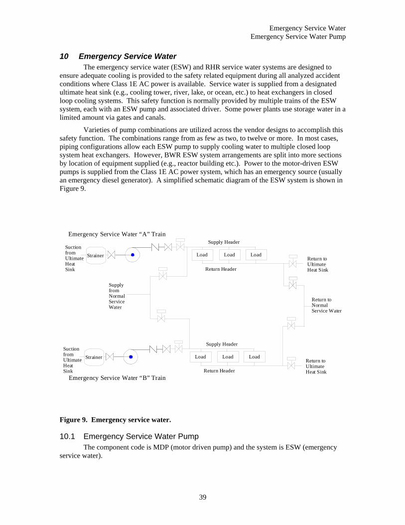
Emergency Service Water Emergency Service Water Pump
39
10 Emergency Service Water The emergency service water (ESW) and RHR service water systems are designed to ensure adequate cooling is provided to the safety related equipment during all analyzed accident conditions where Class 1E AC power is available. Service water is supplied from a designated ultimate heat sink (e.g., cooling tower, river, lake, or ocean, etc.) to heat exchangers in closed loop cooling systems. This safety function is normally provided by multiple trains of the ESW system, each with an ESW pump and associated driver. Some power plants use storage water in a limited amount via gates and canals.
Varieties of pump combinations are utilized across the vendor designs to accomplish this safety function. The combinations range from as few as two, to twelve or more. In most cases, piping configurations allow each ESW pump to supply cooling water to multiple closed loop system heat exchangers. However, BWR ESW system arrangements are split into more sections by location of equipment supplied (e.g., reactor building etc.). Power to the motor-driven ESW pumps is supplied from the Class 1E AC power system, which has an emergency source (usually an emergency diesel generator). A simplified schematic diagram of the ESW system is shown in Figure 9.
Strainer LoadLoad Load
Supply Header
Return Header
Return toUltimate Heat Sink
SuctionfromUltimateHeatSink
Return toNormalService Water
Emergency Service Water “A” Train
Strainer LoadLoad Load
Supply Header
Return Header
Return toUltimate Heat Sink
SuctionfromUltimateHeatSink
Supply fromNormalServiceWater
Emergency Service Water “B” Train
Figure 9. Emergency service water.
10.1 Emergency Service Water Pump The component code is MDP (motor driven pump) and the system is ESW (emergency
service water).
Emergency Service Water Emergency Service Water Strainers
40
10.1.1 Emergency Service Water Pump Component Boundaries The main component of an ESW pump is the pump itself coupled to an AC electric motor for a driver. This component can be in one of two states, standby or running. In the standby condition, starting is accomplished by sensors actuating a circuit breaker. These pumps can also be started manually via remote control switches. Stopping of the pump is accomplished only by operator actions via the control switches or automatic signals designed to protect the pump or driver (e.g., overcurrent). The boundaries include the pump itself and internal piece-parts, the driver, circuit breaker, lubrication or cooling systems, and any sensors, controls, or indication required for operation of the pump.
10.1.2 Emergency Service Water Pump Failure Event Definition Successful operation of an ESW pump is defined for two distinct modes of operation. If the ESW pump is in the standby condition, it must respond to an actuation signal by starting, which includes of obtaining design discharge pressure or flow. Once running, the ESW pump must continue to produce design flow or discharge pressure until its service is no longer needed. The respective failure modes used for evaluating the data are:
FS Failure to Start Examples are: circuit breaker fails to close, pump fails to achieve design flow or pressure, control switch failure, and flow-switch failure.
FR Failure to Run Examples are: excessive bearing vibration, cavitation, decreasing performance (less than design flow or pressure) while running, excessive packing leaks, and loss of lubrication/cooling.
FX Fail to Stop The component fails to stop operating.
ESW pump malfunctions are considered failures to start or run on demand. The pump is considered to fail the start portion of its mission if it fails to reach rated flow and pressure. Once rated flow and pressure have been demonstrated, and a failure is observed, the pump will be considered to have failed its run mission. Testing that demonstrates desired bypass flow will be considered to be a successful start. Pump failures include those failures that are caused by power supply breakers or sensors that are unique to the pump-driver combination. Failures that occurred during testing are included with the failures that occurred during plant transients requiring operation of the ESW pumps.
Pump-driver failures are evaluated to determine the effect on pump operability. In general, if the failure causes the pump to fail to operate, it will be considered a failure. Failures of the sensors or control circuitry to provide input in other systems (e.g., interlocks or indication) will not be considered pump failures.
10.2 Emergency Service Water Strainers The component code is STR (strainer) or SRK (trash rack) and the system is ESW
(emergency service water).
10.2.1 Emergency Service Water Strainer Component Boundaries The main component of an ESW strainer is the strainer itself coupled to an AC electric motor for a driver that rotates the strainer for automatic and set interval cleaning. This component can be in one of two states, standby, or operation, in conjunction with the associated pump. Typically, the strainers will start and operate whenever the pump is running unless there is

Emergency Service Water Emergency Service Water Strainers
41
a problem, such as strainer motor overload. These strainers can also be started manually via remote control switches. Stopping of the strainer is accomplished by operator actions via the control switches or automatic signals designed to protect the strainer or driver (e.g., overcurrent). The boundaries include the strainer itself and internal piece-parts, the motor, circuit breaker, and any sensors, controls, or indication required for operation of the strainer.
10.2.2 Emergency Service Water Strainer Failure Event Definition Successful operation of an ESW strainer is starting from the standby condition, and allowing flow to the downstream portion of the system. The only failure mode used for evaluating the ESW strainer data is:
PG Failure to Allow Flow
Examples are: clogging due to grass/seaweed, and fouling due to organic buildup.
ESW strainer malfunctions are considered failures to allow flow, including loss of the motor, since plugging of the strainer will follow shortly. Strainer failures include those failures that are caused by power supplies or sensors that are unique to the strainer-driver combination. Failures that occurred during testing are included with the failures that occurred during plant transients requiring operation of the ESW strainer.
Strainer motor failures are evaluated to determine the effect on strainer operability. In general, if the failure causes the strainer to fail to operate, it will be considered a failure. Failures of the sensors or control circuitry to provide input in other systems (e.g., interlocks or indication) will not be considered strainer failures.

Emergency Service Water Emergency Service Water Strainers
42
PWR High Pressure Safety Injection Emergency Service Water Strainers
43
11 PWR High Pressure Safety Injection The high pressure safety injection (HPI) system is a subsystem of the emergency core cooling system (ECCS) that functions to provide emergency coolant injection to maintain reactor coolant inventory and provide adequate decay heat removal following a loss of coolant accident (LOCA). The injection function is performed in a relatively short time interval after initiation of the LOCA. The system is typically comprised of two intermediate pressure high flow safety injection (SI) pumps and two or three high-pressure low flow centrifugal charging pumps (CCP); one CCP is an installed spare which can be manually aligned to either train. Positive displacement (reciprocating) charging pumps are not included in this study due to the differences in design and operating characteristics between them and centrifugal pumps. CCF events can affect only the SI pumps, only the CCPs, or both SI pumps and CCPs, so the CCCG for events at a single plant can range from two to five.
Both the CCP and the SI pumps inject directly into the primary loop cold legs, and the SI pumps can be realigned to inject into the hot legs. The normal suction source for the HPSI pumps is the refueling water storage tank (RWST), which contains enough highly borated water to satisfy the injection needs of the core. Figure 10 illustrates the typical flow path for the HPSI system. All pumps and motor operated valves receive power from the 1E emergency power system backed up by the emergency diesel generators.
The SI portion of the system is normally aligned and in the standby mode. The CCP portion of the system is used for normal charging operations and may be in operation at all times. The HPI pumps are started by the engineered safety features actuation system (ESFAS) or may be manually actuated. A SI signal starts the CCP and SI pumps, shifts the charging pump suction to the RWST, isolates normal charging and letdown flow, and completes additional valve lineup changes. The injection phase ends when the RWST reaches the low-level setpoint and the system is realigned for the recirculation phase, which takes suction from the containment sump through the RHR system. Three-loop Westinghouse plants have three centrifugal pumps that are also the only high-pressure injection pumps (CCP and SI are the same). In CE plants and 2-loop Westinghouse plants, CCP pumps do not receive an SI signal and do not perform a safety injection function.

PWR High Pressure Safety Injection PWR High Pressure Safety Injection Pump
44
Refueling Water
Storage Tank
V C T
To Cold Leg
Injection
To Cold Leg
Injection
Hot and Cold Leg Injection
ChargingPumps
Safety InjectionPumps
Figure 10. PWR High Pressure Safety Injection.
11.1 PWR High Pressure Safety Injection Pump The component code is MDP (motor driven pump) and the system is HPI (high pressure
injection).
11.1.1 PWR High Pressure Safety Injection Pump Component Boundaries The main component of an HPI pump is the pump itself. The SI pumps are normally in standby and started by sensors actuating the circuit breaker to the driver, which will in turn operate the pump. These pumps can also be started manually via remote control switches. There is usually one charging pump operating, and it will continue running on a LOCA signal. Stopping of the pump is accomplished only by operator actions via the control switches or automatic signals designed to protect the pumps or motors (e.g., overcurrent, overspeed).
The boundaries include the pump itself, the driver including the circuit breaker, lubrication or cooling systems, and any sensors, controls, or indication required for operation of the pump. Sensors or input logic that affect components other than a single SI or charging pump are not included in the component boundaries.
11.1.2 PWR High Pressure Safety Injection Pump Failure Event Definition Successful operation of an HPI pump is defined for two distinct modes of operation. If the HPSI is in the normal standby condition, it must respond to an actuation signal by starting, which consists of obtaining design discharge pressure and flow. Once running, the HPSI pump must continue to produce design flow and discharge pressure until its service is no longer needed. The respective failure modes used for evaluating the HPI pump data are:
FS Failure to Start Examples are: circuit breaker fails to close, pump fails to achieve design flow or pressure, control switch failure, and flow-switch failure.
PWR High Pressure Safety Injection PWR Coolant Charging Pump
45
FR Failure to Run Examples are: excessive bearing vibration, cavitation, decreasing performance (less than design flow or pressure) while running, excessive packing leaks, and loss of lubrication/cooling.
FX Fail to Stop The component fails to stop operating.
HPSI pump malfunctions are considered failures to start or failures to run. The pump is considered to fail the start portion of its mission if it fails to reach rated flow and pressure. Once rated flow and pressure have been demonstrated, and a failure is observed, the pump will be considered to have failed its run mission. Testing that demonstrates desired bypass flow will be considered to be a successful start. Pump failures include those failures that are caused by power supply breakers or sensors that are unique to the pump-driver combination. Failures that occurred during testing are included with the failures that occurred during plant transients requiring operation of the HPSI pumps.
Pump motor failures are evaluated to determine the effect on pump operability. In general, if the failure causes the pump to fail to operate, it will be considered a failure. Failures of the sensors or control circuitry to provide input in other systems (e.g., interlocks or indication) will not be considered pump failures.
11.2 PWR Coolant Charging Pump The component code is MDP (motor driven pump) and the system is HPI (high pressure
injection).
11.2.1 PWR Coolant Charging Pump Component Boundaries The main component of a CCP pump is the pump itself. The CCP pumps are normally charging to the cold leg. In the event of an SI signal the CCPs are started by sensors actuating the circuit breaker to the driver, shifts the charging pump suction to the RWST, isolates normal charging and letdown flow, and completes additional valve lineup changes. These pumps can also be started manually via remote control switches. Stopping of the pump is accomplished only by operator actions via the control switches or automatic signals designed to protect the pumps or motors (e.g., overcurrent, overspeed).
The boundaries include the pump itself, the driver including the circuit breaker, lubrication or cooling systems, and any sensors, controls, or indication required for operation of the pump. Sensors or input logic that affect components other than a single SI or charging pump are not included in the component boundaries.
11.2.2 PWR Coolant Charging Pump Failure Event Definition Successful operation of a CCP pump is defined for two distinct modes of operation. If the HPSI is in the normal standby condition, it must respond to an actuation signal by starting, which consists of obtaining design discharge pressure and flow. Once running, the CCP pump must continue to produce design flow and discharge pressure until its service is no longer needed. The respective failure modes used for evaluating the CCP pump data are:
FS Failure to Start Examples are: circuit breaker fails to close, pump fails to achieve design flow or pressure, control switch failure, and flow-switch failure.
FR Failure to Run Examples are: excessive bearing vibration, cavitation, decreasing performance (less than design flow or pressure) while running, excessive packing leaks, and loss of lubrication/cooling.

PWR High Pressure Safety Injection PWR High Pressure Safety Injection Motor-Operated Valves
46
FX Fail to Stop The component fails to stop operating.
CCP pump malfunctions are considered failures to start or failures to run. The pump is considered to fail the start portion of its mission if it fails to reach rated flow and pressure. Once rated flow and pressure have been demonstrated, and a failure is observed, the pump will be considered to have failed its run mission. Testing that demonstrates desired bypass flow will be considered to be a successful start. Pump failures include those failures that are caused by power supply breakers or sensors that are unique to the pump-driver combination. Failures that occurred during testing are included with the failures that occurred during plant transients requiring operation of the CCPs.
Pump motor failures are evaluated to determine the effect on pump operability. In general, if the failure causes the pump to fail to operate, it will be considered a failure. Failures of the sensors or control circuitry to provide input in other systems (e.g., interlocks or indication) will not be considered pump failures.
11.3 PWR High Pressure Safety Injection Motor-Operated Valves The component code is MOV (motor operated valve) and the system is HPI (high
pressure injection).
11.3.1 PWR High Pressure Safety Injection Motor-Operated Valve Component Boundaries
The main components of a motor-operated valve are the valve, including its internal piece-part components (e.g. gate, stem), and the operator. The operator includes the circuit breaker, power leads, sensors (flow, pressure, and level), and motor as piece parts. Only sensors unique to the operation of the individual valve are included with the valve for CCF analysis. All MOVs have manual hand wheels, and can be manually operated. AC or DC power is required for valve operation.
The MOVs in the HPSI system are used in the following applications:
• Admitting borated water to the suction of the charging pumps and safety injection pumps,
• Shifting charging pump and safety injection pump suction to the containment sump, and
• Aligning discharge of safety injection pumps from cold leg to hot leg injection.
11.3.2 PWR High Pressure Safety Injection Motor-Operated Valve Failure Event Definition
The function of the HPSI MOVs is to allow borated water flow through the HPSI system into the reactor coolant system. All valves serve as a system containment boundary and would need to close in order to isolate leaks. The failure modes used in evaluating the Safety Injection System MOV data are:
CC Fail to Open The valve must be in the fully open position. Anything less than full open is considered a failure to open.
OO Fail to Close The valve must be fully closed on a close signal, or it is considered a failure to close.
PWR High Pressure Safety Injection PWR High Pressure Safety Injection Check Valves
47
VR Failure to Remain Closed In cases where the motor operated valve has been closed for a substantial period and is then discovered leaking, the failure will be coded as VR. If the discovery is made soon after a system configuration change (i.e., pump operation), then the failure is coded as OO.
A stroke time testing failure is not considered a failure if the valve reached the required open or closed state and no failed piece-parts are reported. Generally, slow stroke times that are not due to a failed piece-part are adjusted and then the valve passes. These are not to be coded as failures. However, if degradation of valve internals was reported and piece-parts are replaced, then the event will be recorded as a failure in the direction of the test and assigned an appropriate degradation value.
Valve failures include functional inoperabilities due to reasons not related to valve hardware malfunctions. Examples are breaker de-energized and locked open (human error), and system conditions (abnormal pressure and temperature) that prevent operation. Failure of the electrical operator without coincident failure of the manual operator is considered a failure. These events are considered individually to determine if the failure occurred within the component boundary, or if the failure was due to external factors such that the event was not a CCF event.
Failures of the operator and circuit breaker are evaluated to determine the ultimate effect on valve operability for assignment of failure mode. For example, a circuit breaker may fail to close, but the resulting effect on the valve is failure to open, so the failure mode is "CC."
11.4 PWR High Pressure Safety Injection Check Valves The component code is CKV (check valve) or CKS (stop check valve) and the system is
HPI (high pressure injection).
11.4.1 PWR High Pressure Safety Injection Check Valve Component Boundaries
The main component of a check valve is the valve itself. This component is operated by system pressure overcoming gravity. Typically, there is no capability to manual open, close, or isolate these valves, however, some valves have manual hand wheels or levers (stop-check) and can be manually closed. No power is required for valve operation. Valves are installed in HPSI systems in the following areas:
• Pump discharge,
• Pump suction,
• Loop injection,
• System inter- or cross-connection, and
• Prevent diversion of flow between trains.
The function of the check valve is to form a conditional boundary (i.e., one direction) between high pressure and low-pressure sections of a system during static conditions. By design, the valve will open to allow flow when the low-pressure section has experienced a pressure increase (e.g., pump start). For the purposes of this study, the boundaries will encompass the valve body including internals (e.g. disk, springs).
PWR High Pressure Safety Injection PWR Containment Sump Strainers
48
11.4.2 PWR High Pressure Safety Injection Check Valve Failure Event Definition
Check valve malfunctions are considered failures to open or close on demand, and failure to stay closed, including excessive leakage through the valve. Examples of the consequences of this failure are an increase in containment leak rate, system drainage, and interfacing system LOCA. Failure modes used to analyze check valve data are:
CC Failure to Open Examples are: Check valve sticks closed and check valve partially opens.
OO Failure to Close Examples are: Check valve doesn’t fully close and failure to re-seat.
VR Failure to Remain Closed
In cases where the check valve has been closed for a substantial period and is then discovered leaking the failure will be coded as VR.
HPSI check valve failures that occurred during testing are included with failures that occurred during plant transients requiring operation of the HPSI check valves.
11.5 PWR Containment Sump Strainers The containment sump strainers are stationary screens in the emergency core cooling
system (ECCS) that function to protect the ECCS pumps and prevent plugging of containment spray nozzles from debris that may be in containment when the sump is used as a coolant source. The containment is used a suction source for the containment recirculation spray pumps, the low-pressure safety injection pumps, and the high-pressure safety injection pumps.
The sump screen assembly is divided into two or more sections to prevent damage and large debris on one side from affecting the other side. Typically, the sump strainers are a combination of a heavy grate (to keep out large debris) and smaller mesh strainers to strain out small debris such as insulation fibers. The containment sump strainers do not have any moving parts or electrical connections.
The component code is STR (strainer) and the system is HPI (high pressure injection).
11.5.1 PWR Containment Sump Strainer Component Boundaries The containment sump strainer includes the strainer screens used to filter debris and the sump area that serves to accumulate coolant for ECCS pumps suction.
11.5.2 PWR Containment Sump Strainer Failure Event Definition Successful operation of the containment sump strainer is allowing flow from the sump to the pumps. The only failure mode used for evaluating the sump strainer data is:
PG Plugged, or Failure to Allow Flow
Examples are: physical damage (to screens) that reduces flow cross-section, and accumulation of debris in sump.
PWR Residual Heat Removal (Low Pressure Safety Injection) PWR Containment Sump Strainers
49
12 PWR Residual Heat Removal (Low Pressure Safety Injection) The Residual Heat Removal (RHR) system is a subsystem of the emergency core cooling
system (ECCS) that functions to provide emergency coolant injection to maintain reactor coolant inventory and provide adequate long term decay heat removal following a loss of coolant accident (LOCA). The low-pressure safety injection function is performed over a relatively long time interval after initiation of the LOCA. The RHR pumps inject directly into the primary loop cold legs and can be realigned to inject into the hot legs. The initial suction source for the RHR pumps is the refueling water storage tank (RWST), which contains enough highly borated water to satisfy the injection needs of the core. During the recirculation phase the pumps take suction from the containment sump and supply flow to the loops or to the suction of the high-pressure safety injection pumps. These pumps also provide for the shutdown cooling function. Figure 11 illustrates the typical flow path for the RHR system. The system is typically comprised of two high capacity centrifugal pumps. The pumps receive power from the 1E emergency power system and are backed up by the emergency diesel generators.
The system is normally aligned and in the standby mode. The RHR pumps are started by the engineered safety features actuation system or may be manually actuated. A safety injection (SI) signal starts the pumps and aligns the pump suction to the RWST. The injection phase ends when the RWST reaches the low-level setpoint and the system is realigned for the recirculation phase.
The RHR system serves several functions by operating in different modes:
• Low pressure safety injection (LPI) mode - to provide low pressure makeup water to the reactor vessel for core cooling under loss of coolant accident (LOCA) conditions,
• Recirculation mode - to remove heat from the PCS by recirculating water from the containment sump to the RCS through the heat exchangers, and
• Shutdown cooling mode – to remove heat from the reactor vessel using a closed-loop, low-pressure, single-phase primary heat transfer loop.
Under accident conditions, the LPI mode is automatically initiated. All other modes require manual system alignment for proper operation. The LPI mode takes suction from the RWST and discharges to the reactor vessel penetrations. The RHR heat exchangers are bypassed in this mode. The recirculation mode is designed to limit the long-term bulk temperature rise of the containment sump water following a design basis LOCA or relief valve actuation following an overpressure transient. A closed path from the containment sump through the RHR loops to the reactor vessel and back to the containment sump through the break can be maintained for long-term decay heat removal from the core. In the shutdown-cooling mode, the RHR system is aligned take suction from the hot leg; pass the coolant through the heat exchangers and back to the cold leg.

PWR Residual Heat Removal (Low Pressure Safety Injection) PWR Residual Heat Removal Pump
50
RefuelingWater
StorageTank
Temp Control Valve
SuctionFromContainmentSump
RHR SuctionFromHot Leg
To RCS
Low Pressure Injection/RHR Train “A”
Temp Control Valve
SuctionFromContainmentSump
RHR SuctionFromHot Leg
Low Pressure Injection/RHR Train “B”To RCS
Figure 11. PWR residual heat removal system.
12.1 PWR Residual Heat Removal Pump The component code is MDP (motor driven pump) and the system is RHR (residual heat
removal).
12.1.1 PWR Residual Heat Removal Pump Component Boundaries The main component of an RHR pump is the pump itself. This component is normally in a standby mode and is started by sensors actuating the circuit breaker to the driver, which will in turn operate the pump. These pumps can also be started up manually via remote control switches. Stopping of the pump is accomplished only by operator actions via the control switches or automatic signals designed to protect the pumps or motors (e.g., overcurrent, overspeed).
The boundaries include the pump itself, the driver including the circuit breaker, lubrication or cooling systems, and any sensors, controls, or indications required for operation of the pump. Sensors or input logic that affect components other than a single RHR pump are not included in the component boundaries.
12.1.2 PWR RHR Failure Event Definition Successful operation of a RHR pump is defined for two distinct modes of operation. If the LPSI system is in the normal standby condition, it must respond to an actuation signal by starting which consists of obtaining design discharge pressure and flow. Once running, the RHR pump must continue to produce design flow and discharge pressure until its service is no longer needed. The respective failure modes used for evaluating the RHR pump data are:
FS Failure to Start Examples are: circuit breaker fails to close, pump fails to achieve design
PWR Residual Heat Removal (Low Pressure Safety Injection) PWR Residual Heat Removal Motor-Operated Valves
51
flow or pressure, control switch failure, and flow-switch failure.
FR Failure to Run Examples are: excessive bearing vibration, cavitation, decreasing performance (less than design flow or pressure) while running, excessive packing leaks, and loss of lubrication/cooling.
FX Fail to Stop The component fails to stop operating.
RHR pump malfunctions are considered failures to start or failures to run. The pump is considered to fail the start portion of its mission if it fails to reach rated flow and pressure. Once rated flow and pressure have been demonstrated, and a failure is observed, the pump will be considered to have failed its run mission. Testing that demonstrates desired bypass flow will be considered to be a successful start. Pump failures include those failures that are caused by power supply breakers or sensors that are unique to the pump-driver combination. Failures that occurred during testing are included with the failures that occurred during plant transients requiring operation of the RHR pumps.
Pump motor failures are evaluated to determine the effect on pump operability. In general, if the failure causes the pump to fail to operate, it will be considered a failure. Failures of the sensors or control circuitry to provide input in other systems (e.g., interlocks or indication) will not be considered pump failures.
12.2 PWR Residual Heat Removal Motor-Operated Valves
12.2.1 PWR RHR Motor-Operated Valve Component Boundaries The main components of a motor-operated valve are the valve, including its internal piece-part components (e.g. gate, stem), and the operator. The operator includes the circuit breaker, power leads, sensors (flow, pressure, and level), and motor as piece parts. Only sensors unique to the operation of the individual valve are included with the valve for CCF analysis. All MOVs have manual hand wheels, and can be manually operated. AC or DC power is required for valve operation.
The MOVs in the RHR system are used in the following applications:
• Provide a suction source from the RWST,
• Allow shifting suction to the containment sump,
• Allow a suction path from the RCS hot legs for shutdown cooling,
• Align discharge for RHR or for safety injection to the hot or cold legs.
12.2.2 PWR RHR Motor-Operated Valve Failure Event Definition All valves serve as a system containment boundary and would need to close to isolate leaks. The failure modes used in evaluating the RHR system MOV data are:
CC Fail to Open The valve must be in the fully open position. Anything less than full open is considered a failure to open.
OO Fail to Close The valve must be fully closed on a close signal, or it is considered a failure to close.
PWR Residual Heat Removal (Low Pressure Safety Injection) PWR Residual Heat Removal Check Valves
52
VR Failure to Remain Closed In cases where the motor operated valve has been closed for a substantial period and is then discovered leaking, the failure will be coded as VR. If the discovery is made soon after a system configuration change (i.e., pump operation), then the failure is coded as OO.
A stroke time testing failure is not considered a failure if the valve reached the required open or closed state and no failed piece-parts are reported. Generally, slow stroke times that are not due to a failed piece-part are adjusted and then the valve passes. These are not to be coded as failures. However, if degradation of valve internals was reported and piece-parts are replaced, then the event will be recorded as a failure in the direction of the test and assigned an appropriate degradation value.
Valve failures include functional inoperabilities due to reasons not related to valve hardware malfunctions. Examples are breaker de-energized and locked open (human error), and system conditions (abnormal pressure and temperature) that prevent operation. Failure of the electrical operator without coincident failure of the manual operator is considered a failure. These events are considered individually to determine if the failure occurred within the component boundary, or if the failure was due to external factors such that the event was not a CCF event.
Failures of the operator and circuit breaker are evaluated to determine the ultimate effect on valve operability for assignment of failure mode. For example, a circuit breaker may fail to close, but the resulting effect on the valve is failure to open, so the failure mode is "CC."
12.3 PWR Residual Heat Removal Check Valves The component code is CKV (check valve) or CKS (stop check valve) and the system is
RHR (residual heat removal).
12.3.1 PWR Residual Heat Removal Check Valve Component Boundaries The main component of a check valve is the valve itself. This component is operated by system pressure overcoming gravity. Typically, there is no capability to manually open, close, or isolate these valves, however, some check valves have manual hand wheels or levers (stop-check) and can be manually closed. No power is required for valve operation. Check valves are installed in LPSI systems in the following areas:
• Pump discharge,
• Pump suction,
• Loop injection, and
• System inter- or cross-connection.
The function of the check valve is to form a conditional boundary (i.e., one direction) between high pressure and low-pressure sections of a system during static conditions. By design, the valve will open to allow flow when the low-pressure section has experienced a pressure increase (e.g., pump start). For the purposes of this study, the boundaries will encompass the valve body including internals (e.g. disk, spring) and operators in the cases of air assisted check valves.

PWR Residual Heat Removal (Low Pressure Safety Injection) PWR Containment Sump Strainers
53
12.3.2 PWR Residual Heat Removal Check Valve Failure Event Definition Check valve malfunctions are considered failures to open or close on demand and, failure to stay closed which includes excessive leakage through the valve. Examples of the consequences of this failure are increased containment leak rate, interfacing systems LOCA, and system drainage. Failure modes used to analyze check valve data are:
CC Failure to Open Examples are: Check valve sticks closed and check valve partially opens.
OO Failure to Close Examples are: Check valve sticks open, valve doesn’t fully close, and failure to re-seat.
VR Failure to Remain Closed
In cases where the check valve has been closed for a substantial period and is then discovered leaking the failure will be coded as VR.
RHR check valves failures that occurred during testing are included with the failures that occurred during plant transients requiring operation of the RHR check valves.
12.4 PWR Containment Sump Strainers The containment sump strainers are stationary screens in the emergency core cooling
system (ECCS) that function to protect the ECCS pumps and prevent plugging of containment spray nozzles from debris that may be in containment when the sump is used as a coolant source. The containment is used a suction source for the containment recirculation spray pumps, the low pressure safety injection pumps, and the high pressure safety injection pumps.
The sump screen assembly is divided into two or more sections to prevent damage and large debris on one side from affecting the other side. Typically, the sump strainers are a combination of a heavy grate (to keep out large debris) and smaller mesh strainers to strain out small debris such as insulation fibers. The containment sump strainers do not have any moving parts or electrical connections.
The component code is STR (strainer) and the system is RHR (residual heat removal).
12.4.1 PWR Containment Sump Strainer Component Boundaries The containment sump strainer includes the strainer screens used to filter debris and the sump area that serves to accumulate coolant for ECCS pumps suction.
12.4.2 PWR Containment Sump Strainer Failure Event Definition Successful operation of the containment sump strainer is allowing flow from the sump to the pumps. The only failure mode used for evaluating the sump strainer data is:
PG Plugged, or Failure to Allow Flow
Examples are: physical damage (to screens) that reduces flow cross-section, and accumulation of debris in sump.

PWR Residual Heat Removal (Low Pressure Safety Injection) PWR Containment Sump Strainers
54
BWR High Pressure Coolant Injection and Reactor Core Isolation Cooling PWR Containment Sump Strainers
55
13 BWR High Pressure Coolant Injection and Reactor Core Isolation Cooling
BWRs can have high-pressure coolant injection (HPCI) and/or reactor core isolation cooling (RCIC) systems. Both the HPCI and the RCIC are single train systems, and are not consequently subject to CCF events by themselves. This analysis combined the failures of pumps across the system boundaries to examine CCFs across these two systems.
The HPCI system supplies high volume, high pressure make-up water to the reactor pressure vessel (RPV) in the event of a small break LOCA which does not result in a rapid depressurization of the reactor vessel. The HPCI system consists of a turbine driven pump, system piping, valves, and controls. The HPCI system is normally in standby when the plant is at power. The HPCI system is normally aligned to take suction on the Condensate Storage Tank (CST) but suction is automatically switched from the CST to the suppression pool upon low CST level or high suppression pool water level. The HPCI system is automatically started in response to decreasing RPV water level or high dry well pressure and is injected into the reactor via the feedwater header, which injects outside the RPV shroud. HPCI is the primary source of makeup if RCS pressure remains high. The HPCI turbine steam supply is from main steam. Figure 12 shows a typical HPCI system.
The RCIC system provides low volume; high-pressure makeup water to the RPV for core cooling when the main steam lines are isolated or the condensate/feedwater system is not available. The RCIC system consists of a turbine driven pump, piping, valves, and controls. The RCIC system is normally shut down and aligned in standby, if the plant is at power. The RCIC system is normally aligned for suction from the CST, but suction is automatically switched from the CST to the suppression pool on low CST level or high suppression pool water level. The RCIC system is automatically started in response to decreasing RPV water level and is injected into the RPV via the feedwater line. Steam to drive the RCIC turbine is routed from main steam. The RCIC system is similar to the HPCI system in terms of components and configuration.
BWR-2 plants do not have HPCI. BWR-3 and BWR-4 plants have HPCI. BWR-5 and –6 plants have HPCS in lieu of HPCI. BWR-2 and Early BWR-3 plants have isolation condenser in lieu of RCIC. BWR-5 and –6 plants do not have RCIC. They have LPCS instead. Therefore, common-cause failures in HPCI/RCIC systems apply only to those BWR-3 plants that have HPCI and RCIC and BWR-4 plants.

BWR High Pressure Coolant Injection and Reactor Core Isolation Cooling BWR High Pressure Coolant Injection and Reactor Core Isolation Cooling Pumps
56
Condensate
Storage Tank
Flow Test Line to CST
InjectionValve
FlowTransmitter
Governor Oil
Operated Trip Valve
Mini - FlowLine
Turbine Exhaust
Steam SupplyIsolation Valve
MainFeedwater
Line
ReactorPressureVessel
SuppressionPool
To Suppression
Pool Relief Valve
To Main
Steam
Figure 12. BWR High Pressure Coolant Injection and Reactor Core Isolation Cooling .
13.1 BWR High Pressure Coolant Injection and Reactor Core Isolation Cooling Pumps The component code is MDP (motor driven pump) and the system is HCI (high pressure
coolant injection).
13.1.1 BWR High Pressure Coolant Injection and Reactor Core Isolation Cooling Pump Component Boundaries
The main component of an HPCI/RCIC pump is the pump itself. This component is normally in a standby mode and is started up by a sensor opening the steam inlet valve to start the steam turbine, which will in turn operate the pump. These pumps can also be started manually via remote control switches. Stopping of the pump is accomplished only by operator actions via the control switches or automatic signals designed to protect the pumps or turbines (e.g., overspeed, steam line valve closure on containment isolation signal, reactor vessel high level, and high turbine exhaust pressure).
The boundaries include the pump itself, the driver including the governor system, lubrication, condensate, or cooling systems, and any sensors, controls, or indication required for operation of the pump. Sensors or input logic that affect components other than a single HPCI/RCIC pump are not included in the component boundaries.
BWR High Pressure Coolant Injection and Reactor Core Isolation Cooling BWR High Pressure Coolant Injection and Reactor Core Isolation Cooling Motor-Operated
Valves
57
13.1.2 BWR High Pressure Coolant Injection and Reactor Core Isolation Cooling Component Pump Failure Event Definition
Successful operation of a HPCI/RCIC pump is defined for two distinct modes of operation. If the HPCI/RCIC is in the normal standby condition, it must respond to an actuation signal by starting, which consists of obtaining design discharge pressure and flow. Once running, the HPCI/RCIC pump must continue to produce design flow and discharge pressure until its service is no longer needed. The respective failure modes used for evaluating the HPCI/RCIC pump data are:
FS Failure to Start Examples are: circuit breaker fails to close, pump fails to achieve design flow or pressure, control switch failure, and flow-switch failure.
FR Failure to Run Examples are: excessive bearing vibration, cavitation, decreasing performance (less than design flow or pressure) while running, excessive packing leaks, and loss of lubrication/cooling.
FX Fail to Stop The component fails to stop operating.
HPCI/RCIC pump malfunctions are considered failures to start or failures to run. The pump is considered to fail the start portion of its mission if it fails to reach rated flow and pressure. Once rated flow and pressure have been demonstrated, and a failure is observed, the pump will be considered to have failed its run mission. Testing that demonstrates desired bypass flow will be considered to be a successful start. Pump failures include those failures that are caused by power supply breakers or sensors that are unique to the pump-driver combination. Failures that occurred during testing are included with the failures that occurred during plant transients requiring operation of the HPCI/RCIC pumps.
Pump-turbine failures are evaluated to determine the effect on pump operability. In general, if the failure causes the pump to fail to operate, it will be considered a failure. Failures of the sensors or control circuitry to provide input in other systems (e.g., interlocks or indication) will not be considered pump failures.
13.2 BWR High Pressure Coolant Injection and Reactor Core Isolation Cooling Motor-Operated Valves The component code is MOV (motor operated valve) and the system is HCI (high
pressure coolant injection).
13.2.1 BWR High Pressure Coolant Injection and Reactor Core Isolation Cooling Motor-Operated Valve Component Boundaries
The main components of a motor-operated valve are the valve, including its internal piece-part components (e.g. gate, stem), and the operator. The operator includes the circuit breaker, power leads, sensors (flow, pressure, and level), and motor as piece parts. Only sensors unique to the operation of the individual valve are included with the valve for CCF analysis. All MOVs have manual hand wheels, and can be manually operated. AC or DC power is required for valve operation.
MOVs are used in the HPCI/RCIC system in the following applications:
• Pump discharge,
• Pump suction,

BWR High Pressure Coolant Injection and Reactor Core Isolation Cooling BWR High Pressure Coolant Injection and Reactor Core Isolation Cooling Air Operated Valves
58
• Loop injection,
• Steam supply.
13.2.2 BWR High Pressure Coolant Injection and Reactor Core Isolation Cooling Motor-Operated Valve Failure Event Definition
During normal plant operations, most of the MOVs remain closed except the condensate storage tank supply line isolation valve and the steam supply line isolation valves. All valves serve as a system containment boundary and would need to close to isolate leaks. The failure modes used in evaluating the isolation condenser MOV data are:
CC Fail to Open The valve must be in the fully open position. Anything less than full open is considered a failure to open.
OO Fail to Close The valve must be fully closed on a close signal, or it is considered a failure to close.
VR Failure to Remain Closed In cases where the motor operated valve has been closed for a substantial period and is then discovered leaking, the failure will be coded as VR.
A stroke time testing failure is not considered a failure if the valve reached the required open or closed state and no failed piece-parts are reported. Generally, slow stroke times that are not due to a failed piece-part are adjusted and then the valve passes. These are not to be coded as failures. However, if degradation of valve internals was reported and piece-parts are replaced, then the event will be recorded as a failure in the direction of the test and assigned an appropriate degradation value.
Valve failures include functional inoperabilities due to reasons not related to valve hardware malfunctions. Examples are breaker de-energized and locked open (human error), and system conditions (abnormal pressure and temperature) that prevent operation. Failure of the electrical operator without coincident failure of the manual operator is considered a failure. These events are considered individually to determine if the failure occurred within the component boundary, or if the failure was due to external factors such that the event was not a CCF event.
Failures of the operator and circuit breaker are evaluated to determine the ultimate effect on valve operability for assignment of failure mode. For example, a circuit breaker may fail to close, but the resulting effect on the valve is failure to open, so the failure mode is "CC."
13.3 BWR High Pressure Coolant Injection and Reactor Core Isolation Cooling Air Operated Valves The component code is AOV (motor operated valve) and the system is HCI (high
pressure coolant injection).
13.3.1 High Pressure Coolant Injection and Reactor Core Isolation Cooling Air Operated Valve Component Boundaries
The main components of an air-operated valve are the valve, including its internal piece-part components (e.g. disk, seat, stem, packing), and the operator. The operator includes the internal air operator piece-parts, the air supply lines specific to the AOV, sensors, solenoids to control the air supply, and the power leads to these solenoids as piece-parts. Only sensors unique to the operation of the individual valve are included with the valve for CCF analysis. Some

BWR High Pressure Coolant Injection and Reactor Core Isolation Cooling BWR High Pressure Coolant Injection and Reactor Core Isolation Cooling Air Operated Valves
59
AOVs have manual hand wheels, and can be manually operated or blocked. AC or DC power is required for solenoid and sensor operation.
The AOVs in the HPCI/RCIC systems are used in the following applications:
• controlling cooling and condensate flow,
• controlling steam condensate drains, and
• exhaust line vacuum breaker isolation valves.
The component code is AOV (air operated valve) and the system is HCI (high pressure coolant injection).
13.3.2 High Pressure Coolant Injection and Reactor Core Isolation Cooling Air Operated Valve Failure Event Definition
During normal plant operations, most of the AOVs remain closed to isolate the high pressure and low-pressure portions of the system. All valves serve as a system containment boundary and would need to close to isolate leaks. The failure modes used in evaluating the HPCI/RCIC AOV data are:
CC Fail to Open The valve must be in the fully open position. Anything less than full open is considered a failure to open.
OO Fail to Close The valve must be fully closed on a close signal, or it is considered a failure to close.
VR Failure to Remain Closed In cases where the motor operated valve has been closed for a substantial period and is then discovered leaking, the failure will be coded as VR. If the discovery is made soon after a system configuration change (i.e., pump operation), then the failure is coded as OO.
A stroke time testing failure is not considered a failure if the valve reached the required open or closed state and no failed piece-parts are reported. Generally, slow stroke times that are not due to a failed piece-part are adjusted and then the valve passes. These are not to be coded as failures. However, if degradation of valve internals was reported and piece-parts are replaced, then the event will be recorded as a failure in the direction of the test and assigned an appropriate degradation value.
Valve failures include functional inoperabilities due to reasons not related to valve hardware malfunctions. Examples are loss of instrument air to the valve operator, control power de-energized, and system conditions (abnormal pressure and temperature) that prevent operation. Failure of the pneumatic operator without coincident failure of the manual operator is still coded as a failure.
Failures of the operator are evaluated to determine the ultimate effect on valve operability for assignment of failure mode. For example, a loss of instrument air may cause the valve to cycle to its fail-safe position, but the resulting effect on the valve is failure to reposition, so the failure mode is failure to operate to that position (if it is readily discernable, otherwise a failure of “CC” is assigned.)

BWR High Pressure Coolant Injection and Reactor Core Isolation Cooling BWR Suppression Pool Strainer
60
13.4 BWR High Pressure Coolant Injection/Reactor Core Isolation Cooling Check Valves The component code is CKV (check valve) or CKS (stop check valve) and the system is
HCI (high pressure coolant injection).
13.4.1 BWR High Pressure Coolant Injection/Reactor Core Isolation Cooling Check Valve Component Boundaries
The main component of a check valve is the valve itself. This component is operated by system pressure overcoming gravity. Typically, there is no capability to manually open, close, or isolate these valves however, some check valves have manual hand wheels or levers (stop-check) and can be manually closed. Other check valves are "air-testable” which should not affect normal component operation and in some cases, the air supply is turned off during operation as a precaution. No power is required for valve operation. Check valves are installed in HPCI/RCIC systems in the following areas:
• Test line,
• Pump suction,
• Injection line,
• Pump turbine steam inlet and exhaust.
The function of the check valve is to form a conditional boundary (i.e., one direction) between high pressure and low-pressure sections of a system during static conditions. By design, the valve will open to allow flow when the low-pressure section has experienced a pressure increase (e.g., pump start). For the purposes of this study, the boundaries will encompass the valve body including internals (e.g. disk, springs).
13.4.2 BWR High Pressure Coolant Injection/Reactor Core Isolation Cooling Check Valve Failure Event Definition
Check valve malfunctions are considered failures to open or close on demand and failure to stay closed which includes excessive leakage through the valve. Failure modes used to analyze check valve data are:
CC Failure to Open Examples are: Check valve sticks closed and check valve partially opens.
OO Failure to Close Examples are: Check valve doesn’t fully close and failure to re-seat.
VR Failure to Remain Closed
In cases where the check valve has been closed for a substantial period and is then discovered leaking the failure will be coded as VR.
HPCI/RCIC check valve failures that occurred during testing are included with the failures that occurred during plant transients requiring operation of the HPCI/RCIC check valves.
13.5 BWR Suppression Pool Strainer The suppression pool strainers are stationary screens in the emergency core cooling
system (ECCS) that function to protect the ECCS pumps. The suppression pool is used a suction
BWR High Pressure Coolant Injection and Reactor Core Isolation Cooling BWR Suppression Pool Strainer
61
source for the RHR pumps, the low pressure core spray, the reactor core isolation cooling, and the high-pressure coolant injection pumps.
Typically, the sump strainers are a combination of a heavy grate (to keep out large debris) and smaller mesh strainers to strain out small debris such as insulation fibers. The suppression pool strainers do not have any moving parts or electrical connections.
The component code is STR (strainer) and the system is RHR (residual heat removal).
13.5.1 BWR Suppression Pool Strainer Component Boundaries The main component of a sump strainer is the strainer itself. This component is normally in a standby mode and is a passive component with no moving parts.
13.5.2 BWR Suppression Pool Strainer Failure Event Definition Successful operation of the containment sump strainer is allowing flow from the sump to the pumps. The only failure mode used for evaluating the sump strainer data is:
PG Plugged, or Failure to Allow Flow
Examples are: physical damage (to screens) that reduces flow cross-section, and accumulation of debris in sump.

BWR High Pressure Coolant Injection and Reactor Core Isolation Cooling BWR Suppression Pool Strainer
62
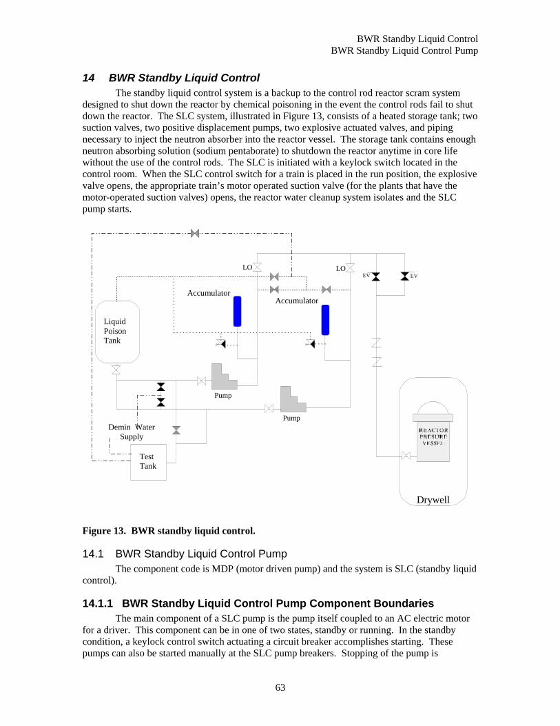
BWR Standby Liquid Control BWR Standby Liquid Control Pump
63
14 BWR Standby Liquid Control The standby liquid control system is a backup to the control rod reactor scram system designed to shut down the reactor by chemical poisoning in the event the control rods fail to shut down the reactor. The SLC system, illustrated in Figure 13, consists of a heated storage tank; two suction valves, two positive displacement pumps, two explosive actuated valves, and piping necessary to inject the neutron absorber into the reactor vessel. The storage tank contains enough neutron absorbing solution (sodium pentaborate) to shutdown the reactor anytime in core life without the use of the control rods. The SLC is initiated with a keylock switch located in the control room. When the SLC control switch for a train is placed in the run position, the explosive valve opens, the appropriate train’s motor operated suction valve (for the plants that have the motor-operated suction valves) opens, the reactor water cleanup system isolates and the SLC pump starts.
Pump
Pump
Liquid Poison Tank
EV EV
Drywell
Demin Water Supply
Test Tank
LOLO
AccumulatorAccumulator
Figure 13. BWR standby liquid control.
14.1 BWR Standby Liquid Control Pump The component code is MDP (motor driven pump) and the system is SLC (standby liquid
control).
14.1.1 BWR Standby Liquid Control Pump Component Boundaries The main component of a SLC pump is the pump itself coupled to an AC electric motor for a driver. This component can be in one of two states, standby or running. In the standby condition, a keylock control switch actuating a circuit breaker accomplishes starting. These pumps can also be started manually at the SLC pump breakers. Stopping of the pump is
BWR Standby Liquid Control BWR Standby Liquid Control Pump
64
accomplished only by operator actions via the control switches or automatic signals designed to protect the pump or driver (e.g., overcurrent).
The boundaries include the pump itself and internal piece-parts, the motor, circuit breaker, lubrication or cooling systems, and any sensors, controls, or indication required for operation of the pump. Sensors or input logic that affect components other than a single SLC pump are not included in the component boundaries.
14.1.2 BWR Standby Liquid Control Pump Failure Event Definition The function of the standby liquid control pumps is to allow borated water flow to the reactor vessel. The pumps must respond to an initiation signal by starting, including reaching design discharge pressure and flow. Once running, the SLC pumps must continue to produce design flow and discharge pressure until their service is no longer needed. The failure modes used in evaluating the SLC system pump data are:
FS Failure to Start Examples are: circuit breaker fails to close, pump fails to achieve design flow or pressure, control switch failure, and flow-switch failure.
FR Failure to Run Examples are: excessive bearing vibration, cavitation, decreasing performance (less than design flow or pressure) while running, excessive packing leaks, and loss of lubrication/cooling.
FX Fail to Stop The component fails to stop operating.
SLC pump malfunctions are considered failures to start or failures to run. The pump is considered to fail the start portion of its mission if it fails to reach rated flow and pressure. Once rated flow and pressure have been demonstrated, and a failure is observed, the pump will be considered to have failed its run mission. Testing that demonstrates desired bypass flow will be considered to be a successful start. Pump failures include those failures that are caused by power supply breakers or sensors that are unique to the pump-driver combination. Failures that occurred during testing are included with the failures that occurred during plant transients requiring operation of the SLC pumps. Since these pumps are rarely demanded, most failures are detected by testing.
Pump motor failures are evaluated to determine the effect on pump operability. In general, if the failure causes the pump to fail to operate, it will be considered a failure. Failures of the sensors or control circuitry to provide input in other systems (e.g., interlocks or indication) will not be considered pump failures.

PWR Main Steam and Pressure Relief System PWR Main Steam Isolation Valves
65
15 PWR Main Steam and Pressure Relief System The PWR main steam isolation valves (MSIVs) are air-actuated valves in the main steam lines that isolate the steam generator in the event of a main steam leak or rupture downstream of the MSIVs.
The steam generator PORVs actuate to lower pressure in the secondary side of the steam generators prior to safety relief valves lifting. This need to lower pressure is normally the result of a high temperature in the reactor coolant system. Additionally, the valves must re-close following the pressure relief and remain closed during operation in order to preserve the secondary coolant boundary and control the heat removal rate. The steam generators PORVs are actuated by an external motive source such as electrical motor, air, nitrogen, hydraulics, or electrical solenoid. Manual initiation can be accomplished by the control room operator if necessary. Figure 14 shows the configuration of the steam generator PORVs and safety valves. The number of steam generator PORVs at a single plant is the same as the number of steam generators at that plant.
Steam Generator
MSIV
Steam Generator
MSIV
Steam Generator
MSIV
InsideContainment
Outside Containment
SG PORVSG Safety Valves
SG Safety Valves
SG Safety Valves
SG PORV
SG PORV
Figure 14. PWR steam generator relief system.
15.1 PWR Main Steam Isolation Valves The main steam system is part of the PWR Steam Generating system that transfers
sensible and decay heat from the reactor coolant system to the turbine and steam auxiliaries during normal operation. Steam leaves the steam generator through a steam line at the top of the steam generator. Each steam line has a main steam isolation valve (MSIVs) outside of the
PWR Main Steam and Pressure Relief System PWR Steam Generator PORV
66
containment building. Typically, the steam lines join outside of the containment building through a cross-connect header and then split into two main steam headers that supply main and auxiliary steam to the turbine and other auxiliaries.
PWR main steam isolation valves are typically hydraulically operated globe valves. The component code is MSV (main steam isolation valve) and the system is MSS (main steam system).
15.1.1 PWR Main Steam Isolation Valve Component Boundaries The main components of a MSIV are the valve, including its internal piece-part components (e.g. disk, seat, stem, packing), and the operator. The operator includes the internal air operator piece-parts, the air supply lines specific to the MSIV, sensors, solenoids to control the air supply, and the power leads to these solenoids as piece-parts. Only sensors unique to the operation of the individual valve are included with the valve for CCF analysis. Some MSIVs have manual hand wheels, and can be manually operated or blocked. AC or DC power is required for solenoid and sensor operation.
15.1.2 PWR Main Steam Isolation Air-Operated Valve Failure Event Definition
The function of the main steam isolation MSIVs is to isolate steam flow to the steam headers to the turbines. The PRA mission for the main steam system is to provide steam to the turbine and steam auxiliaries. The event boundary for the main steam system isolation valves is defined as any condition that does not permit control of the flow from the steam generators. The failure modes used in evaluating the main steam isolation valve data are:
OO Failure to Close Examples are: valve stays open when it should close, valve doesn’t fully close, and failure to re-seat.
Valve failures include functional inoperabilities due to reasons not related to valve hardware malfunctions. Examples are loss of instrument air to the valve operator, control power de-energized, and system conditions (abnormal pressure and temperature) that prevent operation. Failure of the pneumatic operator without coincident failure of the manual operator is considered as a failure. These events are considered individually to determine of the failure occurred within the component boundary, or if the failure was due to external factors such that the event was not a CCF event.
Failures of the operator are evaluated to determine the ultimate effect on valve operability for assignment of failure mode.
Many MSIV failures are detected by testing. Out-of tolerance closing times may initially be attributed to “setpoint drift.” However, failure to close at the correct setpoint is not always due to setpoint drift. Setpoint drift is the result of many random variables and is usually considered a function of time since calibration and setting. A physical degradation mechanism common to multiple valves, such as corrosion of seats and disks, manufacturing or installation defects, etc., are coded as a failure of the valve in the direction of the failure.
15.2 PWR Steam Generator PORV The steam generator PORVs actuate to lower pressure in the secondary side of the steam
generators prior to safety relief valves lifting. This need to lower pressure is normally the result of a high temperature in the reactor coolant system. Additionally, the valves must reclose following the pressure relief and remain closed during operation in order to preserve the
PWR Main Steam and Pressure Relief System PWR Steam Generator PORV
67
secondary coolant boundary and control the heat removal rate. The steam generators PORVs are actuated by an external motive source such as electrical motor, air, nitrogen, hydraulics, or electrical solenoid. The control room operator if necessary can accomplish manual initiation. The number of steam generator PORVs at a single plant is the same as the number of steam generators at that plant.
The component code is dependent on the type of actuator. The component codes to be used here are: RVA (relief valve air or nitrogen operated), RVE (relief valve solenoid operated), RVM (relief valve motor operated), or RVH (relief valve hydraulic operated). The system is MSS (main steam system).
15.2.1 PWR Steam Generator PORV Component Boundaries A sensor actuating the operating medium such as air or an electric motor, which will in turn operate the valve, normally operates this component. These valves can also be manually opened and closed via a remote control switch. In addition to opening to lower pressure, the valves are designed to re-close when the desired pressure is achieved. This may be only slightly less than the opening pressure.
The boundaries include the valve itself, the valve operator, any sensing lines, and the auxiliary equipment needed to open the valve or verify the valve position. Only the sensors and power supplies that provide direct input to the individual valves are included. Air or nitrogen lines leading directly to a single valve are included with the valve; failures of the air or nitrogen systems are not included with the valve. The pneumatic supply is non-safety related; however, all are equipped with safety-related air accumulators with inlet isolation check valves to ensure pressure retention upon loss of air. These are within the component boundary of the PORV – part of the actuator and essential for valve operation in emergency conditions. Other valve actuation logic, breakers, or air systems that affect other valves or other equipment are not considered part of the valve.
15.2.2 PWR Steam Generator PORV Failure Event Definition Successful operation of a steam generator PORV is defined as opening in response to high system pressure, and re-closing when pressure is reduced. The failure modes used in evaluating the data are:
CC Failure to Open Examples are: PORV sticks closed, PORV setpoint over 10% over the limit or words like "excessive" are considered failures, if piece-part(s) are replaced to calibrate a setpoint that was too high, then the PORV is considered failed. A stroke time test failure will be considered a failure if it is reported as "excessive," otherwise it is not a failure.
OO Failure to Close Examples are: valve stays open when it should close, valve doesn’t fully close, and failure to re-seat. Used only whenever a PORV is blocked shut.
VR Failure to Remain Closed
Examples are: Spurious opening, Leakage past the valve seat, and if piece-part(s) are replaced to re-calibrate a setpoint that was low.
Steam generator PORV malfunctions are considered failures to open or close on demand, failure to stay open or closed, including excessive leakage through the valve. Valve failures include those failures that are caused by power supplies or sensors that are unique to the valve.
PWR Main Steam and Pressure Relief System PWR Steam Generator Safety Valves
68
Steam generator PORVs that open in response to an actual system over pressure are not failures. Subsequent failures to reseat completely are defined as a failure to close event.
Valve operator failures are evaluated to determine the effect on valve operability. In general, if the failure causes the valve to fail to operate, it will be considered a valve failure. Failures of the valve to provide input to other systems (such as limit switches) will not be considered valve failures. Accumulator unavailability reflects the unavailability of the PORV when the primary source of gas is lost. This condition is captured in the CCF database as a failure-to-open, but with a decreased p-value (e.g., 0.5).
Most safety and relief valve failures are detected by testing. Out-of tolerance lifting pressures may initially be attributed to “setpoint drift.” However, failure to lift at the correct setpoint is not always due to setpoint drift. Setpoint drift is the result of many random variables and is usually considered a function of time since calibration and setting. A physical degradation mechanism common to multiple valves, such as corrosion bonding and micro galling of seats and disks, manufacturing or installation defects, etc., are coded as a failure of the valve in the direction of the failure. Corrosion bonding and micro galling have been common industry problems related to design problems and operational conditions.
15.3 PWR Steam Generator Safety Valves The steam generator safety valves are part of the secondary cooling system. They
provide both over pressure protection to the steam generators and additional heat removal capacity. The setpoints for a bank of safety valves on a single steam generator are staggered in order to provide the required pressure relief and to prevent exceeding the maximum flow for each valve. Most PWRs have at least 10 steam generator safety valves. Typically, there are four or five safety valves for each steam generator.
The component code is SVV (safety valve) and the system is MSS (main steam system).
15.3.1 PWR Steam Generator Safety Valve Component Boundaries The main component of the safety valve is the valve body, bonnet, spring, seat, disk, nozzle, and pilot assembly (if pilot actuated). This component is operated mechanically by the system operating pressure exceeding the spring or pilot valve setpoint. In addition to opening to lower pressure, the valves are designed to re-close when the desired pressure is achieved, or when system pressure is insufficient to hold the valve open. There are no electrical or instrumentation connections.
15.3.2 PWR Steam Generator Safety Valve Failure Event Definition Successful operation of a safety valve is defined as opening in response to high system pressure, and re-closing when pressure is reduced. The failure modes used in evaluating the data are:
CC Failure to Open Examples are: SV sticks closed, SV setpoint over 10% over the limit or words like "excessive" are considered failures, if piece-part(s) are replaced to calibrate a setpoint that is too high, then the SV is considered failed, a stroke time test failure will be considered a failure if it is reported as "excessive, " otherwise it is not a failure.
OO Failure to Close Examples are: valve stays open when it should close, valve doesn’t fully close, and failure to re-seat. Whenever a SV is blocked shut.
PWR Main Steam and Pressure Relief System PWR Steam Generator Safety Valves
69
VR Failure to Remain Closed
Examples are: Spurious opening, leakage past the valve seats, and if piece-part(s) are replaced to re-calibrate a setpoint that was low.
Safety valve malfunctions are considered failures to open or close on demand, failure to stay open or closed, including excessive leakage through the valve. Safety valves that open in response to an actual system over pressure are not failures. Subsequent failures to reseat completely are defined as a failure to close event.
Most safety and relief valve failures are detected by testing. Out-of tolerance lifting pressures may initially be attributed to “setpoint drift.” However, failure to lift at the correct setpoint is not always due to setpoint drift. Setpoint drift is the result of many random variables and is usually considered a function of time since calibration and setting. A physical degradation mechanism common to multiple valves, such as corrosion bonding and micro galling of seats and disks, manufacturing or installation defects, etc. that change the setpoint greater than 10 percent, are coded as a failure of the valve in the direction of the failure. Corrosion bonding and micro galling have been common industry problems related to design problems and operational conditions.

PWR Main Steam and Pressure Relief System PWR Steam Generator Safety Valves
70

BWR Main Steam, Pressure Relief, and ADS PWR Steam Generator Safety Valves
71
16 BWR Main Steam, Pressure Relief, and ADS The BWR main steam isolation valves (MSIVs) are air-actuated valves in the main steam
lines that isolate the reactor from outside containment in the event of a main steam leak or rupture downstream of the MSIVs.
The BWR pressure safety relief valves (SRV), safety valves, (SVV), and automatic depressurization system (ADS) valves (ADS valves are a sub-set of the SRVs, which are actuated by the ADS) actuate to lower pressure in the BWR primary system. The numbers of SRVs range from 4 to 20; a typical number is 11. This need to lower system pressure may be dictated by system pressure being above normal or by the need to allow injection from lower pressure systems. If valves open due to pressure being above normal, the SRVs must re-close following the pressure relief or remain close during operation in order to preserve the primary coolant boundary. If the SRVs open to allow injection from lower pressure sources, they will close only when system pressure is reduced to near atmospheric. The valves may also be operated manually via a remote control switch. Some SRVs may be actuated by an external motive source such as air or nitrogen or electrical solenoid. A typical BWR MSIV, SRV, and SVV arrangement is shown in Figure 15.
Reactor
Outside
Inside
Safety
Main Steam Isolation Valves
Main Steam Isolation Valves
Safety/Relief Valves (Typically 11 total)
Drywell Drywell
Safety/Relief Valves (Typically 11 total)
Main Steam
Figure 15. BWR main steam pressure relief and ADS.

BWR Main Steam, Pressure Relief, and ADS BWR Main Steam Isolation Valves
72
16.1 BWR Main Steam Isolation Valves The main steam system is part of the BWR core cooling system that transfers sensible and decay heat from the reactor coolant system to the turbine and steam auxiliaries during normal operation. Steam leaves the reactor vessel through four steam lines. Each steam line has two main steam isolation valves (MSIVs) one inside and one outside of the containment building.
Typically, the steam lines join outside of the containment building through a cross-connect header and then split into two main steam headers that supply main and auxiliary steam to the turbine and other auxiliaries.
The component code is MSV (main steam isolation valve) and the system is MSS (main steam system).
16.1.1 BWR Main Steam Isolation Valve Component Boundaries The main components of a MSIV are the valve, including its internal piece-part components (e.g. disk, seat, stem, packing), and the operator. The MSIV actuator sub-component performs the function of moving the valve disk open and closed. The typical pneumatic actuator may include the housing, control circuitry, air pilot, diaphragm, spring, gaskets and seals, orifices, bushings, solenoid valves, pressure regulators, position indication, pneumatic supply lines, pneumatic accumulator, and the accumulator check valves. The operator includes the internal air operator piece-parts, the air supply lines specific to the MSIV, sensors, solenoids to control the air supply, and the power leads to these solenoids as piece-parts. Only sensors unique to the operation of the individual valve are included with the valve for CCF analysis. Some MSIVs have manual hand wheels, and can be manually operated or blocked. AC or DC power is required for solenoid and sensor operation. The valve sub-component performs the function of allowing fluid to flow through the valve or shutting off all flow. The valve includes the valve body, yoke, seating surface, disk or plug, stem, spring, control rings, bellows, packing, gaskets, and seals.
16.1.2 BWR Main Steam Isolation Valve Failure Event Definition The function of the main steam isolation MSIVs is to isolate steam flow to the steam headers to the turbines. The PRA mission for the main steam system is to provide steam to the turbine and steam auxiliaries. The event boundary for the main steam system isolation valves is defined as any condition that does not permit control of the flow from the reactor coolant system.
The failure modes used in evaluating the MSIV data are:
OO Failure to Close Examples are: valve stays open when it should close, valve doesn’t fully close, and failure to re-seat.
MSIV failures include functional inoperabilities due to reasons not related to valve hardware malfunctions. Examples are loss of instrument air to the valve operator, control power de-energized, and system conditions (abnormal pressure and temperature) that prevent operation. Failure of the pneumatic operator without coincident failure of the manual operator is considered as a failure. These events are considered individually to determine of the failure occurred within the component boundary, or if the failure was due to external factors such that the event was not a CCF event.
Many MSIV failures are detected by testing. Out-of tolerance closing times may initially be attributed to “setpoint drift.” However, failure to close at the correct setpoint is not always due to setpoint drift. Setpoint drift is the result of many random variables and is usually considered a function of time since calibration and setting. A physical degradation mechanism common to

BWR Main Steam, Pressure Relief, and ADS BWR Safety Relief Valves
73
multiple valves, such as corrosion of seats and disks, manufacturing or installation defects, etc., are coded as a failure of the valve in the direction of the failure.
16.2 BWR Safety Relief Valves The safety relief valves are dual acting valves: they may be actuated directly by system
pressure (safety mode), or remotely by the operator or the ADS (relief mode). Al safety relief valve discharges are piped directly to the suppression pool.
In the safety mode, the safety relief valves are actuated via a pilot sensing port, which senses main steam line pressure and applies it to the volume inside the bellows. When the pressure inside the bellows overcomes the pilot pre-load and setpoint adjustment spring pressure, the pilot valve disk will open, putting main steam line pressure on top of the second stage piston, opening the second stage disc, relieving pressure off the top of the main valve piston. Main steam line pressure on the bottom of the main valve piston opens the main valve disc and pressure is relieved to the suppression pool. In the relief mode of operation, air pressure is applied to air actuator by energizing the solenoid-operated valve. The air operator directly opens the second stage disc by mechanically depressing the second stage piston. The main valve will then open as described above regardless of main steam system pressure.
The component code is dependent on the type of actuator. The component codes to be used here are: RVA (relief valve air or nitrogen operated), RVE (relief valve solenoid operated), RVM (relief valve motor operated), or RVH (relief valve hydraulic operated). The system is MSS (main steam system).
16.2.1 BWR Safety Relief Valve Component Boundaries This component is normally operated by a sensor actuating the operating medium such as air, nitrogen, or electrical solenoid, which will in turn operate the valve. These valves can also typically be manually opened and closed via a remote control switch. In addition to opening to lower pressure, the valves are designed to re-close when the desired pressure is achieved. This may be only slightly less than the opening pressure or in the case of valves, which open to reduce pressure in preparation for low-pressure injection, may be when system pressure is insufficient to hold the valve open.
The boundaries include the valve itself, the valve operator, any sensing lines, and the auxiliary equipment needed to open the valve or verify the valve position. Only the sensors and power supplies that only provide direct input to the individual valve are included. Air or nitrogen lines leading directly to a single valve are included with the valve; failures of the air or nitrogen systems are not included with the valve. The pneumatic supply is non-safety related; however, all are equipped with safety-related air accumulators with inlet isolation check valves to ensure pressure retention upon loss of air. These are within the component boundary of the PORV – part of the actuator and essential for valve operation in emergency conditions. Other valve actuation logic, breakers, or air systems that affect other valves or other equipment are not considered part of the valve.
16.2.2 BWR Safety Relief Valve Failure Event Definition Successful operation of a relief valve is defined as opening in response to high system pressure, and re-closing when pressure is reduced. The failure modes used in evaluating the data are:
BWR Main Steam, Pressure Relief, and ADS BWR Safety Valve
74
CC Failure to Open Examples are: SV sticks closed, SV setpoint over 10% over the limit or words like "excessive" are considered failures, if piece-part(s) are replaced to calibrate a setpoint that is too high, then the SV is considered failed, a stroke time test failure will be considered a failure if it is reported as "excessive, " otherwise it is not a failure
OO Failure to Close Examples are: valve stays open when it should close, valve doesn’t fully close, and failure to re-seat. Whenever a SV is blocked shut.
VR Failure to Remain Closed
Examples are: Spurious opening, leakage past the valve seats, and if piece-part(s) are replaced to re-calibrate a setpoint that was low.
Relief valve malfunctions are considered failures to open or close on demand, failure to stay open or closed, including excessive leakage through the valve. Valve failures include those failures that are caused by power supplies or sensors that are unique to the valve. Relief valves that open in response to an actual system over pressure are not failures. Subsequent failures to reseat completely are defined as a failure to close event.
Valve operator failures are evaluated to determine the effect on valve operability. In general, if the failure causes the valve to fail to operate, it will be considered a valve failure. Failures of the valve to provide input to other systems (such as limit switches) will not be considered valve failures. Accumulator unavailability reflects the unavailability of the PORV when the primary source of gas is lost. This condition is captured in the CCF database as a failure-to-open, but with a decreased p-value (e.g., 0.5).
Most safety and relief valve failures are detected by testing. Out-of tolerance lifting pressures may initially be attributed to “setpoint drift.” However, failure to lift at the correct setpoint is not always due to setpoint drift. Setpoint drift is the result of many random variables and is usually considered a function of time since calibration and setting. A physical degradation mechanism common to multiple valves, such as corrosion bonding and micro galling of seats and disks, manufacturing or installation defects, etc., are coded as a failure of the valve in the direction of the failure. Corrosion bonding and micro galling have been common industry problems related to design problems and operational conditions.
16.3 BWR Safety Valve
16.3.1 BWR Safety Valve Component Boundaries The safety valves are spring loaded, direct acting valves, lifting when steam pressure
reaches or exceeds the spring tension. The safety valves relieve directly to the drywell atmosphere. The safety valve includes only the valve itself and the mechanical (spring) operator. The operator is an integral part of the valve. This component is operated mechanically by the system operating pressure exceeding the spring setpoint. In addition to opening to lower pressure, the valves are designed to re-close when the desired pressure is achieved, or when system pressure is insufficient to hold the valve open. There are no electrical or instrumentation connections.
The component code is SVV (safety valve) and the system is MSS (main steam system).

BWR Main Steam, Pressure Relief, and ADS BWR Safety Valve
75
16.3.2 BWR Safety Valve Failure Event Definition Successful operation of a safety valve is defined as opening in response to high system pressure, and reclosing when pressure is reduced. The failure modes used in evaluating the data are:
CC Failure to Open Examples are: SV sticks closed, SV setpoint over 10% over the limit or words like "excessive" are considered failures, if piece-part(s) are replaced to calibrate a setpoint that is too high, then the SV is considered failed, a stroke time test failure will be considered a failure if it is reported as "excessive, " otherwise it is not a failure
OO Failure to Close Examples are: valve stays open when it should close, valve doesn’t fully close, and failure to re-seat. Whenever a SV is blocked shut.
VR Failure to Remain Closed
Examples are: Spurious opening, leakage past the valve seats, and if piece-part(s) are replaced to re-calibrate a setpoint that was low.
Safety valve malfunctions are considered failures to open or close on demand, failure to stay open or closed, including excessive leakage through the valve. Safety valves that open in response to an actual system over pressure are not failures. Subsequent failures to reseat completely are defined as a failure to close event.
Most safety and relief valve failures are detected by testing. Out-of tolerance lifting pressures may initially be attributed to “setpoint drift.” However, failure to lift at the correct setpoint is not always due to setpoint drift. Setpoint drift is the result of many random variables and is usually considered a function of time since calibration and setting. A physical degradation mechanism common to multiple valves, such as corrosion bonding and micro galling of seats and disks, manufacturing or installation defects, etc. that change the setpoint greater than 10 percent, are coded as a failure of the valve in the direction of the failure. Corrosion bonding and micro galling have been common industry problems related to design problems and operational conditions.

BWR Main Steam, Pressure Relief, and ADS BWR Safety Valve
76
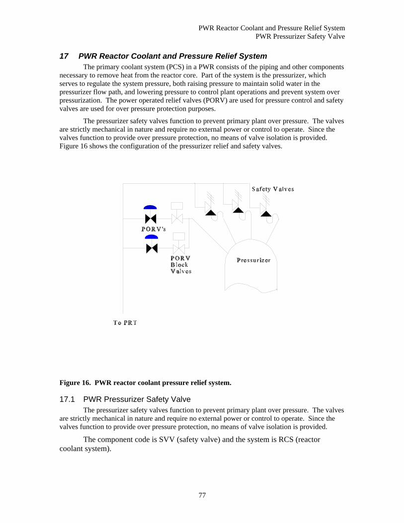
PWR Reactor Coolant and Pressure Relief System PWR Pressurizer Safety Valve
77
17 PWR Reactor Coolant and Pressure Relief System The primary coolant system (PCS) in a PWR consists of the piping and other components necessary to remove heat from the reactor core. Part of the system is the pressurizer, which serves to regulate the system pressure, both raising pressure to maintain solid water in the pressurizer flow path, and lowering pressure to control plant operations and prevent system over pressurization. The power operated relief valves (PORV) are used for pressure control and safety valves are used for over pressure protection purposes.
The pressurizer safety valves function to prevent primary plant over pressure. The valves are strictly mechanical in nature and require no external power or control to operate. Since the valves function to provide over pressure protection, no means of valve isolation is provided. Figure 16 shows the configuration of the pressurizer relief and safety valves.
Figure 16. PWR reactor coolant pressure relief system.
17.1 PWR Pressurizer Safety Valve The pressurizer safety valves function to prevent primary plant over pressure. The valves
are strictly mechanical in nature and require no external power or control to operate. Since the valves function to provide over pressure protection, no means of valve isolation is provided.
The component code is SVV (safety valve) and the system is RCS (reactor coolant system).
PWR Reactor Coolant and Pressure Relief System Pressurizer PORV Motor-Operated Block Valves
78
17.1.1 PWR Pressurizer Safety Valve Component Boundaries The pressurizer safety valve includes only the valve itself and the mechanical (spring) operator. The operator is an integral part of the valve. The system operating pressure exceeding the spring setpoint operates this component mechanically. In addition to opening to lower pressure, the valves are designed to re-close when the desired pressure is achieved, or when system pressure is insufficient to hold the valve open. There are no electrical or instrumentation connections.
17.1.2 PWR Pressurizer Safety Valve Failure Event Definition Successful operation of a safety valve is defined as opening in response to high system pressure, and reclosing when pressure is reduced. The failure modes used in evaluating the data are:
CC Failure to Open Examples are: SV sticks closed, SV setpoint over 10% over the limit or words like "excessive" are considered failures, if piece-part(s) are replaced to calibrate a setpoint that is too high, then the SV is considered failed, a stroke time test failure will be considered a failure if it is reported as "excessive, " otherwise it is not a failure
OO Failure to Close Examples are: valve stays open when it should close, valve doesn’t fully close, and failure to re-seat. Whenever a SV is blocked shut.
VR Failure to Remain Closed
Examples are: Spurious opening, leakage past the valve seats, and if piece-part(s) are replaced to re-calibrate a setpoint that was low.
Safety valve malfunctions are considered failures to open or close on demand, failure to stay open or closed, including excessive leakage through the valve. Safety valves that open in response to an actual system over pressure are not failures. Subsequent failures to reseat completely are defined as a failure to close event.
Most safety and relief valve failures are detected by testing. Out-of tolerance lifting pressures may initially be attributed to “setpoint drift.” However, failure to lift at the correct setpoint is not always due to setpoint drift. Setpoint drift is the result of many random variables and is usually considered a function of time since calibration and setting. A physical degradation mechanism common to multiple valves, such as corrosion bonding and micro galling of seats and disks, manufacturing or installation defects, etc., are coded as a failure of the valve in the direction of the failure. Corrosion bonding and micro galling have been common industry problems related to design problems and operational conditions.
17.2 Pressurizer PORV Motor-Operated Block Valves The component code is MOV (motor operated valve) and the system is RCS (reactor
coolant system).
17.2.1 Pressurizer PORV Motor-Operated Block Valve Component Boundaries
The main components of a motor-operated valve are the valve, including its internal piece-part components (e.g. gate, stem), and the operator. The operator includes the circuit breaker, power leads, sensors (flow, pressure, and level), and motor as piece parts. Only sensors
PWR Reactor Coolant and Pressure Relief System PWR Pressurizer Power Operated Relief Valves
79
unique to the operation of the individual valve are included with the valve for CCF analysis. All MOVs have manual hand wheels, and can be manually operated. AC or DC power is required for valve operation.
The PORV block MOVs are used to isolate the PORVs to prevent the loss of primary coolant. They are normally open. The block MOVs would be closed remotely manually if the associated PORV leaks, or doesn’t reseat fully following a transient.
17.2.2 Pressurizer PORV Motor-Operated Block Valve Failure Event Definition
The function of the PORV block MOVs is to isolate leakage from the primary coolant system through the PORV. The failure modes used in evaluating the PORV block MOV data are:
CC Fail to Open The valve must be in the fully open position. Anything less than full open is considered a failure to open.
OO Fail to Close The valve must be fully closed on a close signal, or it is considered a failure to close.
VR Failure to Remain Closed In cases where the motor operated valve has been closed for a substantial period and is then discovered leaking, the failure will be coded as VR. If the discovery is made soon after a system configuration change (i.e., pump operation), then the failure is coded as OO.
A stroke time testing failure is not considered a failure if the valve reached the required open or closed state and no failed piece-parts are reported. Generally, slow stroke times that are not due to a failed piece-part are adjusted and then the valve passes. These are not to be coded as failures. However, if degradation of valve internals was reported and piece-parts are replaced, then the event will be recorded as a failure in the direction of the test and assigned an appropriate degradation value.
Valve failures include functional inoperabilities due to reasons not related to valve hardware malfunctions. Examples are breaker de-energized and locked open (human error), and system conditions (abnormal pressure and temperature) that prevent operation. Failure of the electrical operator without coincident failure of the manual operator is considered a failure. These events are considered individually to determine if the failure occurred within the component boundary, or if the failure was due to external factors such that the event was not a CCF event.
Failures of the operator and circuit breaker are evaluated to determine the ultimate effect on valve operability for assignment of failure mode. For example, a circuit breaker may fail to close, but the resulting effect on the valve is failure to open, so the failure mode is "CC."
17.3 PWR Pressurizer Power Operated Relief Valves The pressurizer PORVs automatically actuate to lower pressure in the event of a pressure
increase. The PORVs are not required in order to prevent over pressurization but rather function to increase plant operability. The PORVs may also be manually actuated. During shutdown conditions, the PORVs may provide cold over pressure protection. In order to provide cold over pressure protection, operator action is required to reset the automatic lift setpoints.
The component code is dependent on the type of actuator. The component codes to be used here are: RVA (relief valve air or nitrogen operated), RVE (relief valve solenoid operated),

PWR Reactor Coolant and Pressure Relief System PWR Pressurizer Power Operated Relief Valves
80
RVM (relief valve motor operated), or RVH (relief valve hydraulic operated). The system is RCS (reactor coolant system).
17.3.1 PWR Pressurizer Power Operated Relief Valve Component Boundaries
The pressurizer PORV consists of the valve itself along with control and power systems that are specific to the individual PORV. The air supply or gas accumulator to each individual valve is included with that valve. The instrument air system upstream of the PORV air supply isolation valve is not included. Specifically excluded are indication circuitry and control and power systems that are not specific to an individual PORV, but that provide input to multiple PORVs.
17.3.2 PWR Pressurizer Power Operated Relief Valve Failure Event Definition
Successful operation of a relief valve is defined as opening in response to high system pressure, and reclosing when pressure is reduced. The failure modes used in evaluating the pressurizer PORV data are:
CC Failure to Open Examples are: PORV sticks closed, PORV setpoint over 10% over the limit or words like "excessive" are considered failures, if piece-part(s) are replaced to calibrate a setpoint that was too high, then the PORV is considered failed. A stroke time test failure will be considered a failure if it is reported as "excessive," otherwise it is not a failure.
OO Failure to Close Examples are: valve stays open when it should close, valve doesn’t fully close, and failure to re-seat. Used only whenever a PORV is blocked shut.
VR Failure to Remain Closed
Examples are: Spurious opening, Leakage past the valve seat, and if piece-part(s) are replaced to re-calibrate a setpoint that was low.
Relief valve malfunctions are considered failures to open or close on demand, failure to stay open or closed, including excessive leakage through the valve. Valve failures include those failures that are caused by power supplies or sensors that are unique to the valve. Relief valves that open in response to an actual system over pressure are not failures. Subsequent failures to reseat completely are defined as a failure to close event.
Valve operator failures are evaluated to determine the effect on valve operability. In general, if the failure causes the valve to fail to operate, it will be considered a valve failure. Failures of the valve to provide input to other systems (such as limit switches) will not be considered valve failures. Accumulator unavailability reflects the unavailability of the PORV when the primary source of gas is lost. This condition is captured in the CCF database as a failure, but with a decreased p-value (e.g., 0.5).
Most safety and relief valve failures are detected by testing. Out-of tolerance lifting pressures may initially be attributed to “setpoint drift.” However, failure to lift at the correct setpoint is not always due to setpoint drift. Setpoint drift is the result of many random variables and is usually considered a function of time since calibration and setting. A physical degradation mechanism common to multiple valves, such as corrosion bonding and micro galling of seats and disks, manufacturing or installation defects, etc., are coded as a failure of the valve in the

PWR Reactor Coolant and Pressure Relief System PWR Pressurizer Power Operated Relief Valves
81
direction of the failure. Corrosion bonding and micro galling have been common industry problems related to design problems and operational conditions.

BWR Primary Containment Pressure Suppression System BWR Pressure Suppression Chamber Vacuum Breakers
83
18 BWR Primary Containment Pressure Suppression System BWR containment systems provide a multi-barrier pressure suppression containment.
The containment systems are composed of: a primary containment, the pressure suppression systems; and a secondary containment, the reactor building.
The primary containment consists of a drywell, which encloses the reactor vessel, a pressure suppression chamber which stores a large volume of water, a connecting vent system between the drywell and water pool, isolation valves, containment cooling systems, and other service equipment.
The secondary containment consists of a reactor building, which completely encloses the pressure suppression primary containment. The structure provides secondary containment when the primary containment is in service, and primary containment during periods when the primary containment is open, as during refueling.
There are several design concepts currently in use at BWRs. The Mark I or “drywell-torus” design features an inverted light bulb drywell connected via vent pipes to a torus shaped suppression pool. The next design is the Mark II or “over-under” containment. The containment is conical shaped with the suppression pool located below the drywell. Vertical vent pipes in turn connect the drywell to the suppression pool. The latest design is the Mark III containment. Again, a pressure suppression type, but the suppression pool is located below and to the sides of the drywell. A weir wall with horizontal vents connects the drywell with the suppression pool.
18.1 BWR Pressure Suppression Chamber Vacuum Breakers The vacuum breakers discharge from the suppression chamber into the drywell to
equalize pressure and prevent a backflow of water from the suppression pool into the vent header system. These valves are of the swing check valve type. In series with the vacuum breakers are isolation valves (typically MOVs), which serve to keep the penetration sealed during normal operations. When a vacuum is sensed, the isolation valve receives an open signal and opens. The vacuum breaker opens due to the differential pressure and equalizes the pressure. The isolation valve is not included in the CCF study. The component code is CKB (vacuum breaker) and the system is CVR (containment vacuum relief). Additional vacuum breakers discharge from the reactor building atmosphere to the suppression chamber. These vacuum breakers are not to be included with this component.
18.1.1 BWR Pressure Suppression Chamber Vacuum Breaker Component Boundaries
The vacuum breaker consists of the valve itself.
18.1.2 BWR Pressure Suppression Chamber Vacuum Breakers Failure Event Definition
Successful operation of a vacuum breaker is defined as opening in response to high vacuum, and reclosing when vacuum is reduced. The failure modes used in evaluating the pressurizer PORV data are:
CC Failure to Open Examples are: vacuum breaker sticks closed, vacuum breaker setpoint over 10% over the limit or words like "excessive" are considered failures, if piece-part(s) are replaced to calibrate a setpoint that was too high, and then the vacuum breaker is considered failed. A stroke time test failure will be considered a failure if it is reported as "excessive," otherwise it is not a failure.

BWR Primary Containment Pressure Suppression System BWR Pressure Suppression Chamber Vacuum Breakers
84
OO Failure to Close Examples are: valve stays open when it should close, valve doesn’t fully close, and failure to re-seat.
VR Failure to Remain Closed
Examples are: Spurious opening, Leakage past the valve seat, and if piece-part(s) are replaced to re-calibrate a setpoint that was low.
Vacuum breaker malfunctions are considered failures to open or close on demand, failure to stay open or closed, including excessive leakage through the valve. Valve failures include those failures that are caused by power supplies or sensors that are unique to the valve. Vacuum breakers that open in response to an actual system over vacuum are not failures. Subsequent failures to reseat completely are defined as a failure to close event.

Component Cooling Water Systems Component Cooling Heat Exchanger
85
19 Component Cooling Water Systems Both PWRs and BWRs have closed loop cooling water systems. The intent is to gather failure data on all closed loop cooling water systems. However, BWR PRAs do not depend on these systems to mitigate accident scenarios as much as the PWRs. The descriptions contained within are based on the PWR closed loop cooling water systems.
The component cooling water system (CCW) removes heat from safety related loads: the safety injection pumps, charging pumps, RHR pumps and heat exchangers; and from non safety related loads, including the reactor coolant pump thermal barriers. The CCW serves as an intermediate system between the radioactive fluid systems and the service water system.
The CCW is a closed loop system where water flows from the coolant pumps through heat exchangers. Cooling headers service the safety related (essential) loads, and non safety related (non essential) loads. Some of the CCW pumps are normally in service, while the rest serve as standby pump(s). Heat removed from the various components is transferred to the Service Water System via the component cooling heat exchangers.
There are several configurations of pumps and headers. The CCW system generally consists of two or more pumps, two heat exchangers, a surge tank, cooling lines to various components being cooled, and associated piping, valves, and instrumentation. Figure 17 provides an illustration of a typical flow path for the CCW.
Figure 17. Component cooling water system.
19.1 Component Cooling Heat Exchanger The component code is HTX (heat exchanger) and the system is CCW (component cooling water
system).
Component Cooling Water Systems Component Cooling Water Pumps
86
19.1.1 Component Cooling Water Heat Exchanger Component Boundaries The CCW heat exchangers transfer heat from the CCW to the service water system, which is the ultimate heat sink. The main component of a CCW heat exchanger is the heat exchanger itself. It consists of the main tank (shell) and internal cooling water tubes. The service water system on the heat exchanger side of any isolation valves or control valves in included; the remainder of the service water system is not.
Heat exchangers associated with cooling loads of the component cooling water system are not within the boundary of the component cooling water system and are to be included within the loads boundary.
19.1.2 Component Cooling Water Heat Exchanger Failure Event Definition Successful operation of a component cooling water heat exchanger is defined as heat transfer above the minimum design basis requirements. The only failure mode used in evaluating CCW heat exchanger data is:
PG Plugged or Failure to Transfer Heat.
Examples are reduction in flow affecting heat transfer rate, temperature switch failure, and biological fouling.
Failures that occurred during testing are included with the failures that occurred during plant transients requiring operation of the CCW heat exchangers.
19.2 Component Cooling Water Pumps The component code is MDP (motor driven pump) and the system is CCW (component cooling water
system).
19.2.1 Component Cooling Water Pump Component Boundaries The main component of a component cooling water pump is the pump itself. This component is normally running. A standby pump is started by sensors actuating the circuit breaker to the driver, which will in turn start the pump. These pumps can also be started up manually via remote control switches. Stopping of the pump is accomplished only by operator actions via the control switches or automatic signals designed to protect the pumps or motors (e.g., overcurrent, low suction pressure, and high radiation).
The boundaries include the pump itself, the motor including the circuit breaker, lubrication or cooling systems, and any sensors, controls, or indication required for operation of the pump. Sensors or input logic that affect components other than a single pump are not included in the component boundaries.
19.2.2 Component Cooling Water Pump Failure Event Definition Successful operation of a component cooling water pump is defined for two distinct modes of operation. The component cooling water system is a normally operating system. Normally running component cooling water pumps must continue to produce design flow and discharge pressure until the operator shuts down the pump. The standby pump must respond to an actuation signal by starting, which consists of obtaining design discharge pressure and flow. The standby pump should automatically start on the failure of the operating pump. The operating pumps will trip on a high radiation condition in a CCW loop. The respective failure modes used for evaluating the component cooling water pump data are:
FS Failure to Start Examples are: circuit breaker fails to close, pump fails to achieve design flow or pressure, control switch failure, and flow-switch failure.
FR Failure to Run Examples are: excessive bearing vibration, cavitation, decreasing performance (less than design flow or pressure) while running, excessive packing leaks, and loss of lubrication/cooling.
FX Fail to Stop The component fails to stop operating.

Component Cooling Water Systems Component Cooling Water Pumps
87
Component cooling water pump malfunctions are considered failures to start or failures to run. The pump is considered to fail the start portion of its mission if it fails to reach rated flow and pressure. Once rated flow and pressure have been demonstrated, and a failure is observed, the pump will be considered to have failed its run mission. Pump failures include those failures that are caused by power supply breakers or sensors that are unique to the pump-driver combination. Failures that occurred during testing are included with the failures that occurred during plant transients requiring operation of the containment spray pumps.
Pump motor failures are evaluated to determine the effect on pump operability. In general, if the failure causes the pump to fail to operate, it will be considered a failure. Failures of the sensors or control circuitry to provide input in other systems (e.g., interlocks or indication) will not be considered pump failures.


