System and Application Technical Landscape EXTERNAL
34
European Maritime Safety Agency System and Application Technical Landscape 1 ICT Architecture System and Application Technical Landscape
Transcript of System and Application Technical Landscape EXTERNAL

European Maritime Safety Agency System and Application Technical Landscape
1
ICT Architecture
System and Application Technical Landscape

European Maritime Safety Agency System and Application Technical Landscape
2
Document History
Title System and Application Technical Landscape
Version 27 from 16/05/2014

European Maritime Safety Agency System and Application Technical Landscape
3
Table of Contents
Definitions, Acronyms and Abbreviations ................................................. 4
1. Introduction and Objectives ............................................................ 6
2. System Landscape ........................................................................ 7
2.1. High Level Network Schema ............................................................................... 7
2.2. Data Links ....................................................................................................... 7
2.3. Network Security .............................................................................................. 7
2.4. Proxy Policy ..................................................................................................... 8
2.5. Network Load Balancing .................................................................................... 9
2.6. High Level Virtual Infrastructure Schema ............................................................. 9
2.7. Virtual Infrastructure Services ............................................................................ 9
2.8. Application Requirements For Virtual Infrastructure ............................................. 10
2.9. Environments ................................................................................................. 10
2.10. Disaster Recovery ........................................................................................... 13
3. Application Landscape .................................................................. 17
3.1. Architecture Overview ..................................................................................... 17
3.2. Client Environment and Client Tier .................................................................... 18
3.2.1. Web Browser Environment ...................................................................... 18
3.2.2. Client Application ................................................................................... 19
3.2.3. External Systems ................................................................................... 19
3.3. Application Environment .................................................................................. 20
3.3.1. Application Server .................................................................................. 20
3.3.2. EIS Tier ................................................................................................ 21
3.4. Security ......................................................................................................... 24
3.5. Reporting Platform .......................................................................................... 24
3.6. Geographic Information System ....................................................................... 24
3.6.1. Electronic Nautical Charts ........................................................................ 24
3.7. Logging ......................................................................................................... 24
3.8. Storing Times and Dates .................................................................................. 25
4. Service Oriented Architecture ....................................................... 26
4.1. Service Consumers ......................................................................................... 27
4.2. Shared Service Infrastructure ........................................................................... 27
5. LDAP Structure for Maritime Applications........................................ 28
5.1. LDAP Structure ............................................................................................... 28
5.2. Authentication Service ..................................................................................... 28
5.3. Authorization Services ..................................................................................... 29
6. Software Versioning Scheme ........................................................ 30
7. Summary ................................................................................... 31
Annex 1 ............................................................................................ 33
European Maritime Safety Agency System and Application Technical Landscape
4
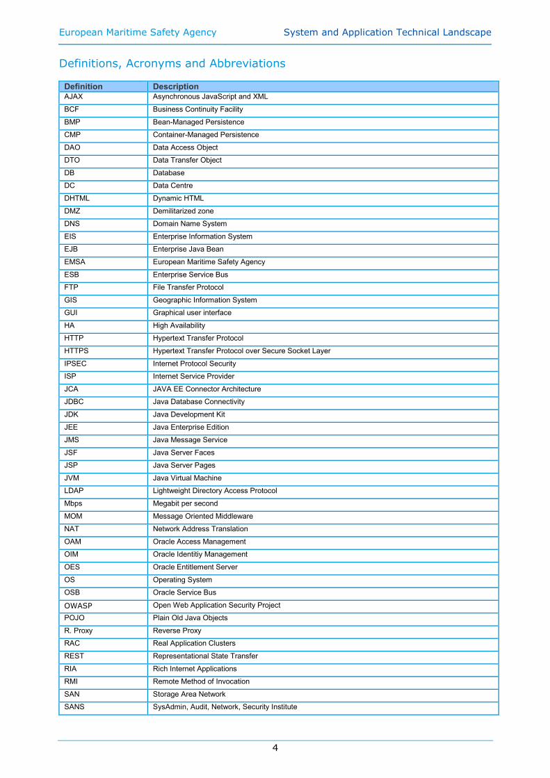
Definitions, Acronyms and Abbreviations Definition Description AJAX Asynchronous JavaScript and XML
BCF Business Continuity Facility
BMP Bean-Managed Persistence
CMP Container-Managed Persistence
DAO Data Access Object
DTO Data Transfer Object
DB Database
DC Data Centre
DHTML Dynamic HTML
DMZ Demilitarized zone
DNS Domain Name System
EIS Enterprise Information System
EJB Enterprise Java Bean
EMSA European Maritime Safety Agency
ESB Enterprise Service Bus
FTP File Transfer Protocol
GIS Geographic Information System
GUI Graphical user interface
HA High Availability
HTTP Hypertext Transfer Protocol
HTTPS Hypertext Transfer Protocol over Secure Socket Layer
IPSEC Internet Protocol Security
ISP Internet Service Provider
JCA JAVA EE Connector Architecture
JDBC Java Database Connectivity
JDK Java Development Kit
JEE Java Enterprise Edition
JMS Java Message Service
JSF Java Server Faces
JSP Java Server Pages
JVM Java Virtual Machine
LDAP Lightweight Directory Access Protocol
Mbps Megabit per second
MOM Message Oriented Middleware
NAT Network Address Translation
OAM Oracle Access Management
OIM Oracle Identitiy Management
OES Oracle Entitlement Server
OS Operating System
OSB Oracle Service Bus
OWASP Open Web Application Security Project
POJO Plain Old Java Objects
R. Proxy Reverse Proxy
RAC Real Application Clusters
REST Representational State Transfer
RIA Rich Internet Applications
RMI Remote Method of Invocation
SAN Storage Area Network
SANS SysAdmin, Audit, Network, Security Institute

European Maritime Safety Agency System and Application Technical Landscape
5
sFTP Secure File Transfer Protocol
SMTP Simple Mail Transfer Protocol
SRM Site Recovery Manager
SOA Service Oriented Architecture
SSL Secure Socket Layer
TB Tera Bytes (i.e. 1012 bytes or 1 million mega bytes)
UDDI Universal Description Discovery and Integration
VLAN Virtual Local Area Network
VM Virtual Machine
WLI WebLogic Integrator
WLS WebLogic Server
XHTML Extensible Hypertext Markup Language
XWS WS Security implementation from Sun Microsystems

European Maritime Safety Agency System and Application Technical Landscape
6
1. Introduction and Objectives
This document describes EMSA System and Application landscape. Its main objective is to
document the technical solutions used by EMSA at System level and to provide directions on
options and preferable technologies to be considered at Application Level.
Although the System and Application Landscape described in this document are EMSA
guiding lines, this does not mean that no deviations are allowed.
Exceptions can be proposed and they will be considered on a case by case basis; if it is
found that is the best technical implementation for the requirement or there is no other way
of doing it, this exception will be accepted.
Also suggestions for innovation are welcome and if they bring added value to the landscape,
they will be included.
The document is organized in several chapters:
• Chapter 1: Introduction and Objectives.
• Chapter 2: Describes the System Landscape and the Technical solutions implements
at systems and network levels.
• Chapter 3: Describes the Application Landscape and preferable options to be used at
the Application level.
• Chapter 4: Describes the conceptual Service Oriented Architecture (SOA) to which
the applications should comply
• Chapter 5: Describes the LDAP structure to be used by all Maritime Applications
• Chapter 6: Describes the software versioning scheme
• Chapter 7: Presents a summary of the system and application landscape

European Maritime Safety Agency System and Application Technical Landscape
7
2. System Landscape
2.1. HIGH LEVEL NETWORK SCHEMA
EMSA Primary site
High level network schema
Figure 1 - Primary site. High level network schema
2.2. DATA LINKS
Data Links
• 2 Internet ISP - active/active using BGP - BGP autonomous system and routing fully managed by EMSA - 100 Mbps each - 256 Provided independent IP addresses • 1 sTESTA link - EU private network - 2 Mbps • 1 GEANT link - Reserved to the CleanSeaNet project for high speed image transfer - 1 Gbps
2.3. NETWORK SECURITY
Two layers of firewall protection:
• Checkpoint R75.40 2-nodes clusters;
• Cisco ASA;

European Maritime Safety Agency System and Application Technical Landscape
8
Reverse proxies for incoming connections (currently handling the following protocols: HTTP,
HTTPS and SFTP). The network is segmented using VLAN’s.
DMZs
•DMZ-1: reverse proxies, DNS servers, other services exposed to Internet •DMZ-2: application servers and database servers (Front/Back End VLANs)
Monitoring of security events is currently achieved through a SIEM (Security Information
Event Management) system including Suricata, Splunk, F5 ASM module on top of EMSA F5
reverse proxy.
2.4. PROXY POLICY
The following rules should be followed:
• Accessing EMSA web applications should be always through HTTPS;
• Reverse proxies are used for all incoming connections from outside networks (Internet
and sTESTA);
• All incoming connections shall pass through our reverse proxies;
• All incoming SSL connections are terminated in the reverse proxies;
• Proxies are always responsible for the SSL encryption and decryption;
• Proxies are always responsible for creation of the SSL connections;
• 1-way SSL is used for human to system interfaces while 2-way SSL should be used for
system to system interfaces;
• All SSL outgoing connections shall use the proxy. Any outgoing SSL connection shall be
initiated as plain HTTP by the applications to the proxy, where the SSL will be initiated
for the outgoing SSL connection. The protocol used to request the proxy the creation of
an outgoing HTTPS connection, involve the usage of an EMSA URL naming convention
(<standard_URL>.f5 URL’s) and some F5 configurations.
Figure 2: Proxy policy
Proxy Devices
• 2 x F5 Big IP v5000 Series

European Maritime Safety Agency System and Application Technical Landscape
9
2.5. NETWORK LOAD BALANCING
The F5 appliances form a redundant cluster that can perform load balancing for web
applications in any VLAN on EMSA network. The design of any new system or application
should preferably implement load balancing with node fail detection on this equipment.
2.6. HIGH LEVEL VIRTUAL INFRASTRUCTURE SCHEMA
2.7. VIRTUAL INFRASTRUCTURE SERVICES
The following services are offered to VMs and application environments:
• Basic monitoring with Nagios;
• Performance monitoring with vCenter Operations;
• VM-level backup with Networker or Netapp SnapMgr for Virtual Infrastructure.
Exceptionally also Networker agent-based backup can be implemented.
• Deployment of a VM or environment1;
• Cloning of a VM or environment;
• Snapshotting of a VM or environment2;
• Exporting as OVF a VM or environment;
• Hardware resource allocation changes3;
1 Subject to being included in the EMSA Template catalogue, currently including:
- Linux Red Hat Enterprise Server or CentOS in version 5 or version 6; - As above, with WebLogic or with Oracle DBMS; - Latest Microsoft Windows servers.
2 Subject to the following policy: the snapshot must be rolled back, or removed, in one week time to avoid performance penalties;
Figure 3 - High Level infrastructure

European Maritime Safety Agency System and Application Technical Landscape
10
• Upgrade of VMware tools and virtual hardware;
• Troubleshooting.
2.8. APPLICATION REQUIREMENTS FOR VIRTUAL INFRASTRUCTURE
Applications and systems hosted in the EMSA Virtual Datacentre must respect the following
requirements:
• Base OS must be chosen out of the current EMSA template catalogue4;
• Compatibility with the latest VMware virtual hardware specifications (currently version
8);
• Hardware provisioning done according to a principle of fit-for-purpose;
• Compatibility with vMotion.
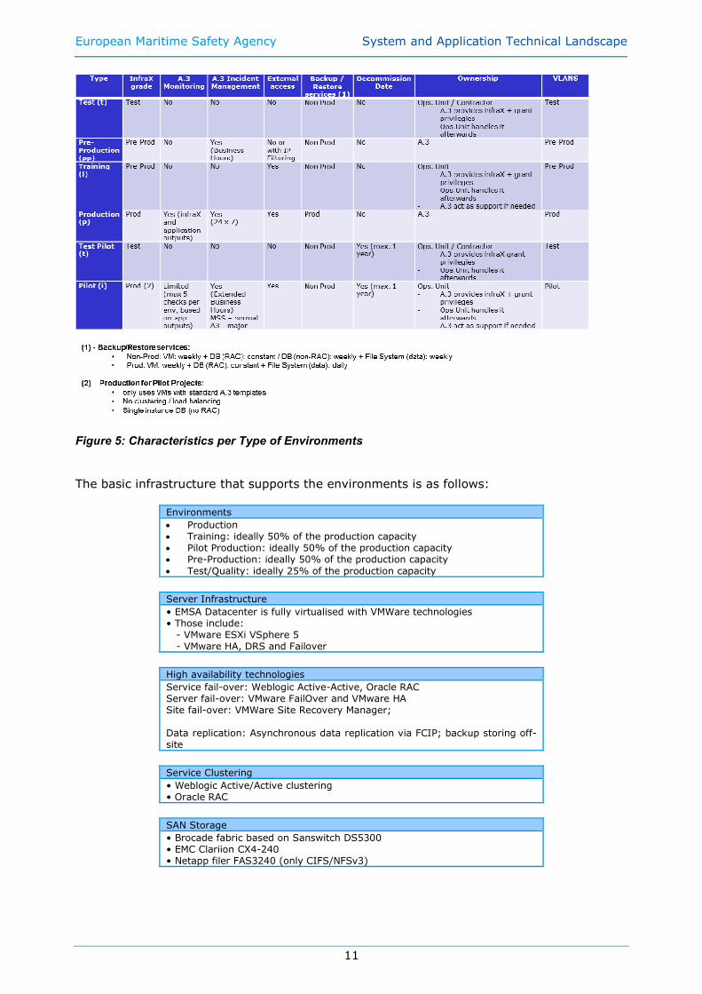
2.9. ENVIRONMENTS
EMSA has defined 6 possible different types of environments for the Maritime Applications.
The following picture presents an overview of them.
Figure 4: Types of Environments
The following figure shows detailed information related to each type of environment.
3 Subject to the following policy: CPU, Memory, disk and network for any VM should be fit for purpose, and oversized VMs should be avoided to reduce contention issues and overhead. Granting more resources is subject to a trend analysis of the use of current resources also looking at vCenter Operations performance indicators, and takes into account its recommendation. VMs oversized are reported on a regular basis and are subject to downsizing. 4 See note 1 on the previous page.
European Maritime Safety Agency System and Application Technical Landscape
11
Figure 5: Characteristics per Type of Environments
The basic infrastructure that supports the environments is as follows:
Environments
• Production • Training: ideally 50% of the production capacity • Pilot Production: ideally 50% of the production capacity • Pre-Production: ideally 50% of the production capacity
• Test/Quality: ideally 25% of the production capacity
Server Infrastructure
• EMSA Datacenter is fully virtualised with VMWare technologies • Those include: - VMware ESXi VSphere 5 - VMware HA, DRS and Failover
High availability technologies
Service fail-over: Weblogic Active-Active, Oracle RAC Server fail-over: VMware FailOver and VMware HA Site fail-over: VMWare Site Recovery Manager; Data replication: Asynchronous data replication via FCIP; backup storing off-site
Service Clustering
• Weblogic Active/Active clustering • Oracle RAC
SAN Storage
• Brocade fabric based on Sanswitch DS5300 • EMC Clariion CX4-240 • Netapp filer FAS3240 (only CIFS/NFSv3)
European Maritime Safety Agency System and Application Technical Landscape
12
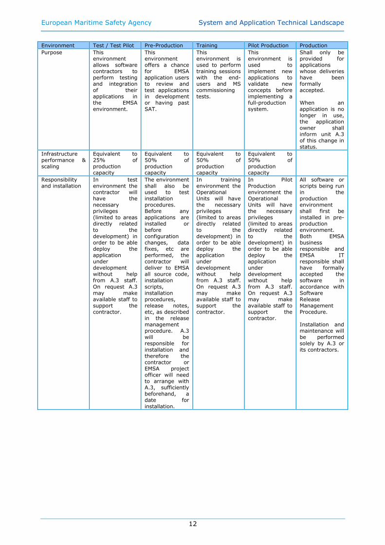
Environment Test / Test Pilot Pre-Production Training Pilot Production Production
Purpose This environment allows software contractors to perform testing and integration of their applications in the EMSA environment.
This environment offers a chance for EMSA application users to review and test applications in development or having past SAT.
This environment is used to perform training sessions with the end-users and MS commissioning tests.
This environment is used to implement new applications to validate new concepts before implementing a full-production system.
Shall only be provided for applications whose deliveries have been formally accepted. When an application is no longer in use, the application owner shall inform unit A.3 of this change in status.
Infrastructure performance & scaling
Equivalent to 25% of production capacity
Equivalent to 50% of production capacity
Equivalent to 50% of production capacity
Equivalent to 50% of production capacity
Responsibility and installation
In test environment the contractor will have the necessary privileges (limited to areas directly related to the development) in order to be able deploy the application under development without help from A.3 staff.
On request A.3 may make available staff to support the contractor.
The environment shall also be used to test installation procedures. Before any applications are installed or before configuration changes, data fixes, etc are performed, the contractor will deliver to EMSA all source code, installation
scripts, installation procedures, release notes, etc, as described in the release management procedure. A.3 will be responsible for installation and therefore the contractor or EMSA project officer will need to arrange with A.3, sufficiently beforehand, a date for installation.
In training environment the Operational Units will have the necessary privileges (limited to areas directly related to the development) in order to be able deploy the application under development without help from A.3 staff.
On request A.3 may make available staff to support the contractor.
In Pilot Production environment the Operational Units will have the necessary privileges (limited to areas directly related to the development) in order to be able deploy the application under development without help
from A.3 staff. On request A.3 may make available staff to support the contractor.
All software or scripts being run in the production environment shall first be installed in pre-production environment. Both EMSA business responsible and EMSA IT responsible shall have formally accepted the software in
accordance with Software Release Management Procedure. Installation and maintenance will be performed solely by A.3 or its contractors.

European Maritime Safety Agency System and Application Technical Landscape
13
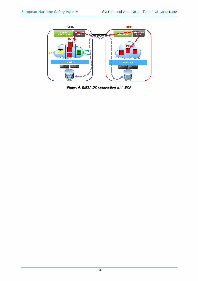
2.10. DISASTER RECOVERY
EMSA’s Business Continuity Facility (BCF) is hosted in Porto in the premises of a commercial
hosting provider. The BCF is a fully equipped replica of the main site in terms of servers,
network equipment, internet connectivity, storage and middleware, and as such it may
function as either the main production site for an application, or as back-up site. This choice
may be made on a per application basis and depends on the EMSA needs, the application’s
replication design and capabilities, and the desired SL.
Any new system or application must conform by design to one of the business continuity
approaches foreseen so far:
1) ON/OFF model:
The servers and services that constitute the system or application are active and
visible on the network only in the main site. They are kept in sync in the secondary
site with some middleware or low level replica technology like Dataguard for
backends, or virtual machine cloning or storage array based replication for front
ends. But the replicated systems are always inactive on the secondary site in an off-
state and not visible on the network unless the recovery procedure is executed.
Taking over in that case means executing a procedure to stop the systems in the
main site (if possible), execute a last synchronisation (if possible), stop the
synchronisation flows, then restart the replicated systems in the secondary site
changing all the parameters that differ in the two sites like network configuration,
internal DNS entries, pointers to database or cartographic servers or to any other
horizontal service platform always available in both sites like LDAP, Single Sign On,
DNS etc…. Eventually, the external DNS entry should be changed to point external
Internet users to the public IP of the system or application in the new site.
According to this model, it is still possible to have the same internal FQDN for the
application servers in both sites, as servers are active and visible on the network
only in one site at a time, and when taking over, the A records of the internal DNS
can be changed to reflect the different IP address space in the new site.
2) ON/ON model:
The servers and services that constitute the system or application are active and
ready to take over at any time in both sites. Synchronisation rely on the features of
the application or middleware used rather than on a low-level cloning and
transferring of the virtual machines, offering either a fully multi-master active/active
approach like Active Directory, or some type of distributed geo-cluster, or anyway an
autonomous system which keeps data and configuration in sync between the two
legs in the two sites. Taking over in that case is a simpler procedure like activating
some built-in system or application feature to switch to the other site, possibly
requiring some internal and external DNS changes, or can be even fully transparent.
According to this model, different FQDNs and IPs for the application servers in the
two sites must be chosen, as servers are active and visible on the network in both
sites at any time.
Note: it is not accepted to design ON/ON systems where the virtual machines on the two
sides have the same internal DNS FQDN.
The ON/ON model, when supported by the application or middleware, might guarantee
faster and seamless fail-over procedure, hence it is the preferred approach.
The following figure exemplifies how the interconnection of current EMSA’s production
environment with the BCF is envisaged and also points to the use of several
replication/back-up systems at different levels of the infrastructure:
European Maritime Safety Agency System and Application Technical Landscape
14
Figure 6: EMSA DC connection with BCF

European Maritime Safety Agency System and Application Technical Landscape
15
The figure presented hereafter depicts the connection between the applications currently deployed at EMSA and the data replication to BCF
performed by Oracle RAC:
Figure 7: Business Continuity Facility
European Maritime Safety Agency System and Application Technical Landscape
16
Key elements of the actual BCF architecture are:
1) the two sites are connected through an IPSEC tunnel over an high performance link
2) the two sites use different private and public IP address ranges
3) the internal DNS zone emsa.local, containing server’s FQDN, is shared between the
two sites;
4) the external IP address space in each of the two sites is a different C-class of
Provider Independent IPs whose routing advertisements is managed directly by
EMSA routers
a. 91.231.216.0/24 => Primary site;
b. 91.231.217.0/24 => Secondary site;
5) the external DNS zone “emsa.europa.eu” is unique across the sites, it is delegated to
EMSA, and it is kept in sync between the two sites with master-slave DNS
replication;
6) data and systems are kept in sync through either:
a. Oracle Dataguard for backend;
b. Storage array replication for most of the front end virtual machines;
c. Ad hoc application built-in replication technologies, like active directory
replication, or Microsoft continuous cluster replication for Exchange and SQL.
d. Ad hoc scripts for data transfer.
7) Rerouting of Internet users to the BCF is done with DNS technologies
New applications development should always be BCF friendly by being compliant with the
following requirements:
• Bandwidth required for data and system alignment should be kept to a manageable
amount to allow continuous replication over a non-dedicated medium bandwidth link. A
bandwidth estimation for data synchronization between EMSA DC and BCF, through
Oracle Data Guard and other technologies, shall be provided;
• A fail-over procedure to BCF shall be provided together with one to fail back to EMSA;
• A list of all the application dependencies which need to be resolved in the BCF and main
production site for the application to run shall be provided:
o Web services
o Data sources
o Other application(s)
o Security constraints
o Infrastructural services
o Etc…
• Connections to other machines should always be configured by referring to the machine
name, never by referring to the IP address directly.
European Maritime Safety Agency System and Application Technical Landscape
17
3. Application Landscape
EIS TierOther Information
Systems
Business Tier
Web Tier
Client Tier
Message Oriented
Middleware
Oracle 11g
Database
Security
OS Server Platform - LINUX RedHat
Application Server
Web Container
Provided by JEE Server, or Tomcat
Java Server Pages, Java Server Faces , Servlets, Portlets
Web
Services
WebLogic Application Server (10.3.6), JBoss
EJB Container,
Provided by JEE Server
Session Beans, Message-Driven Beans
Entity Beans (CMP, BMP) Hibernate, iBatis, POJO
POJO
JDBC JCA JMS
Standard Classes
Hibernate, iBatis, POJO
POJO
OS Desktop Client System Platform – Windows, Linux
(X)HTML
+JavaScript
[SVG]
[RSS]
Web Browser Environment
IE (9.x), Firefox (18.x)
HTTP
HTTPS
Web Services
RMI
Client Application
Web Services
External Systems
S
C
W
B
EAuthentication and
Authorization
openLDAP
DB Custom schema
Physical and Network Security
Logical Security
X
Log4j
MVC
ESB
Oracle Service Bus 11g
JMS
Figure 8: Application landscape
3.1. ARCHITECTURE OVERVIEW
EMSA IT systems should follow state of the art JAVA PLATFORM, ENTERPRISE EDITION
VERSION 7 n-tier architecture. Figure 8 represents the preferable EMSA IT architecture
where the major tiers are:
Client Environment
Client Tier:
Client Tier is a JEE application front-end that provides communication with human users or with others external systems. For details, refer to chapter3.2
Server Environment
Web Tier:
Web Tier connects user interface on a Client Tier with business logic on a Business Tier. For details, refer to chapter 3.3.1, (a)
Business Tier:
Business Tier provides transaction processing logic (business logic) and data processing logic (data management). Business processes and business components should not be implemented outside this tier. For details, refer to chapter 3.3.1, (b)
EIS Tier:
EIS (Enterprise Information System) Tier consists of all enterprise information systems, such as databases or other information systems. ESB and Message Oriented Middleware are also included in this tier.

European Maritime Safety Agency System and Application Technical Landscape
18
For details, refer to chapter 3.3.2
Client Tier is the only tier of the Client Environment and it’s by definition a distributed and
separated tier.
Web Tier, Business Tier and EIS Tier are part of the Server Environment hosted at EMSA;
EIS Tier (and its components) is usually a separated tier implemented on top of a separated
server environment and depending on the complexity, the system architect may decide
between a complete distributed architecture where all tiers are distributed in separated
server environments or a mixed architecture where some tiers may share one server
environment.
Operation systems options for the different environments are:
Client Environment
• Windows 7 • LINUX distribution (RedHat, Suse, Ubuntu or Fedora) desktop V5/6
Server Environment
• LINUX Redhat server 6 (64 bits) • Windows Server 2008
3.2. CLIENT ENVIRONMENT AND CLIENT TIER
3.2.1. Web Browser Environment
The majority of EMSA applications are delivered to the final user via a browser based
interface. A Web UI's advantage is that no additional software needs to be installed on client
side and minimal demands are placed on the client platform.
Because a HTML Thin Client GUI is limited by markup language / JavaScript capabilities,
others resources can add to build Rich Clients providing better user experience through the
Web Browser. Applications must be 100% compatible with, at least, the following browsers
or higher versions:
Web Browsers
• Microsoft Internet Explorer 9 and later • Mozilla Firefox 18 and later
HTML page serves as a host for Rich Clients built with different technologies:
Client Tier Technologies
• HTML 5 • Javascript • Tag Libraries • AdobeAir (to be allowed only on case by case basis) • WebGL
Preferred JavaScript Libraries
• Ext JS • jQuery
Technologies used to implement Rich Internet Applications in the Client Tier can also have
strong relationships with the technologies used in the Web Tier (e.g. Tag Libraries)
described in chapter 3.3.1.
Usage of Java Applets should be limited to very particular situations and the decision to
allow this will be taken on a case by case basis.
European Maritime Safety Agency System and Application Technical Landscape
19
3.2.2. Client Application
Due to some business requirements (e.g. operation in disconnected mode, access to the
local file system, …), some applications may require a Fat Client.
In order to create a unified technology platform, and to support all operating platforms in
use at EMSA or EMSA clients, preference will be for using the Java language. As an
alternative, EMSA may allow use of Adobe AIR technology.
A mechanism for deploying and updating the client application at the remote PC will be
needed (Java Webstart will be preferred). Dependencies on runtime components not already
part of standard EMSA PC configurations will be regarded as negative.
Because EMSA needs to support other organisations within the Member States, any
application to be installed on a client will need to be cross-platform, covering at least the
platforms listed earlier in this document5.
Usually, a client application will need also to connect to the server side of the system in
order to perform business actions (e.g. data synchronization). Several technologies can be
used to address this client-server connection:
Client-Server connection technologies
• HTTP or HTTPS • Web Services • OGC WMS, WFS and KML • JSON • SOAP, with WS-*
Communications to servers shall be done using web services, exceptions may be granted on
request. Exposed Web Services shall always be protected with Authentication and
Authorization. Important business data should always be stored on servers managed by
A.3, if this requirement cannot be met (due to business requirements, impossibility to
connect, …) a procedure for providing data back-ups needs to be foreseen.
In case development of a fat client is proposed, this needs to be discussed with A.3 and
agreements on installation requirements, connection technology and data back-up need to
be reached before starting development.
Mobile application platforms
• iOS 7 and up • Android 4.0 and later
Increasingly mobile devices are used for accessing web based information systems. Where
possible, in order to avoid creating multiple platform dependent solutions, such
developments should be based on simple website access, with appropriate changes applied
to the UI to take into account the smaller screen size, reduced bandwidth and touch based
controls used by mobile devices. In cases where business requirements cannot be reached
using a mobile optimised website, at least the application platforms and version mentioned
above need to be supported.
3.2.3. External Systems
External systems will also act as clients to EMSA systems creating the need of integrating
different software systems used by different organizations (business partners). The system
integration helps to automate collaboration processes and improve business performance.
De-facto standard technologies should be used to inter-connect external systems with EMSA
systems:
5 If the application is to be used only by EMSA this requirement can be reduced to
supporting Windows 7. An application installer compatible with EMSA’s MS System Center
needs to be provided.
European Maritime Safety Agency System and Application Technical Landscape
20
External systems integration technologies
• Web Services • OGC WMS, WFS and KML – should follow INSPIRE Directive 2007/2/E • SOAP, with WS-* • sFTP /FTP
WS-* standards will be the preferred way for securing, and enabling QoS, reliability, etc. for
these web services.
3.3. APPLICATION ENVIRONMENT
3.3.1. Application Server
EMSA architecture is based on the standard JEE version 5. The following Application Servers
should be used as the base Web and EJB containers:
Application Servers
• Weblogic Application Server (latest version) • JBoss (latest version)
New development or ‘significant’6 changes to existing applications should always target the
latest version of the application server in use at EMSA. For existing applications, EMSA will
assess the desirability vs the risks of upgrading the underlying application server on a case
by case basis.
Simple applications, where distribution is not foreseen, the EJB container is not needed; see
below for details.
(a) Web Tier
The delivery of Rich GUI based on Web Browsers is achieved by a set of components located
in this tier and in close relationship with the Client Tier. Those components may vary
depending on the technical solution adopted and level of complexity required for the Rich
GUI; major technologies are presented in the next table: Web Tier Technologies
• JSP – Java Server Pages • JSF – Java Server Faces • Portlets • Rich server side components7
Portal technology
• Liferay Enterprise Edition
Simple applications, that only require a Web Container can use:
Web Container
• Tomcat (latest stable version)
Web Services are used to provide communication between loosely connected system
components and are the preferable mechanism to expose services to external
systems/applications. Several technologies could be adopted:
Web Services technologies
• AXIS 2 • Spring Web Services
6 Significant shall be understood as any change resulting in a change of either major or
minor versioning number (see further for a description of the version numbering scheme in
use at EMSA) 7 No preferable solution yet. On a case by case, other technologies that enable Rich Web
base clients can be used
European Maritime Safety Agency System and Application Technical Landscape
21
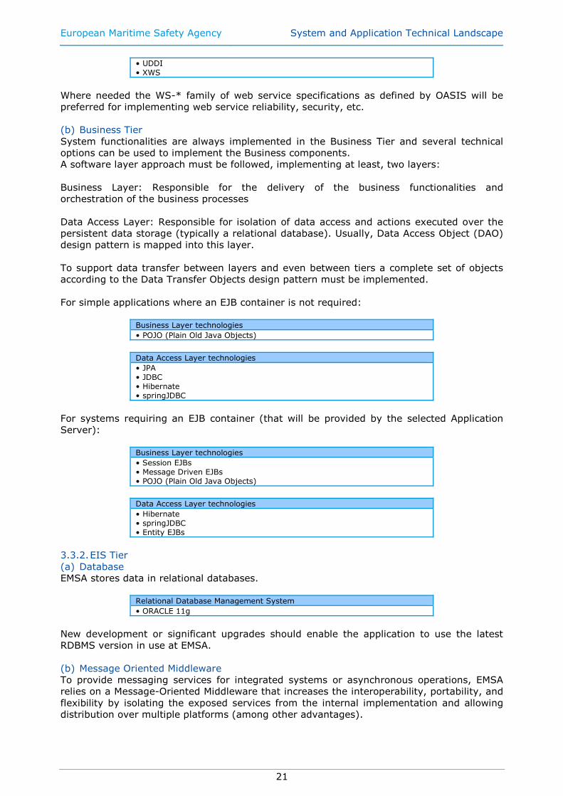
• UDDI • XWS
Where needed the WS-* family of web service specifications as defined by OASIS will be
preferred for implementing web service reliability, security, etc.
(b) Business Tier
System functionalities are always implemented in the Business Tier and several technical
options can be used to implement the Business components.
A software layer approach must be followed, implementing at least, two layers:
Business Layer: Responsible for the delivery of the business functionalities and
orchestration of the business processes
Data Access Layer: Responsible for isolation of data access and actions executed over the
persistent data storage (typically a relational database). Usually, Data Access Object (DAO)
design pattern is mapped into this layer.
To support data transfer between layers and even between tiers a complete set of objects
according to the Data Transfer Objects design pattern must be implemented.
For simple applications where an EJB container is not required:
Business Layer technologies
• POJO (Plain Old Java Objects)
Data Access Layer technologies
• JPA • JDBC • Hibernate • springJDBC
For systems requiring an EJB container (that will be provided by the selected Application
Server):
Business Layer technologies
• Session EJBs • Message Driven EJBs • POJO (Plain Old Java Objects)
Data Access Layer technologies
• Hibernate • springJDBC • Entity EJBs
3.3.2. EIS Tier
(a) Database
EMSA stores data in relational databases.
Relational Database Management System
• ORACLE 11g
New development or significant upgrades should enable the application to use the latest
RDBMS version in use at EMSA.
(b) Message Oriented Middleware
To provide messaging services for integrated systems or asynchronous operations, EMSA
relies on a Message-Oriented Middleware that increases the interoperability, portability, and
flexibility by isolating the exposed services from the internal implementation and allowing
distribution over multiple platforms (among other advantages).
European Maritime Safety Agency System and Application Technical Landscape
22
Asynchronous messaging is the preferred method for exchanging data between internal
applications. JMS will be the preferred manner for consuming and producing messages. The
use of asynchronous message should enable better decoupling between applications
(compared to web services), allow a more up-to-date system state (compared to batch
processing), increased scalability (due to MOM underpinnings) and improved configurability
and oversight of the system integrations (through use of the ESB). Asynchronous
messaging over JMS will also be the preferred method for request/reply messaging
paradigm.
Message Oriented Middleware
• WebLogic JMS
(c) Other Information Systems
Any other Information Systems inside EMSA is considered to be in the EIS tier.
Integration can be done using several techniques; preferable methods of integration are:
Internal systems integration technologies
• JCA – JAVA EE Connector Architecture • Web Services (like an external system in the Client Tier) ), those can be based on either SOAP, REST or JSON
For services that are to be consumed by other systems inside of EMSA or to the outside the
more formally defined SOAP web services are preferred. Asynchronous communication
(based on call backs) should be used where possible.
Compared to the JMS based integration described above, more effort will be required to
ensure the consumers / producers deal with service unavailability, scalability or reliability
issues, therefore integration using asynchronous JMS is encouraged.
(d) Authentication and Authorization
EMSA applications that require user authentication and authorization should rely on a
directory to store user credentials, roles and access privileges.
User directory technologies
• openLDAP
Although the use of a database schema to cope with these functions is a common practice,
it has several disadvantages and should be avoided.
EMSA owns a centralized system for Identity Management that encompasses two different
aspects: SSO for authentication and central user management based on Oracle technology.
For new applications development, developers should focus on:
• Relying on SSO for authentication
• Using JAAS for in-app authorization
• Weblogic App Server needs to be configured accordingly (JAAS + OAM agent)
• Use an RBAC model
• All administration of security principals will be handled through the Oracle Identity
Manager.
The following figure gives an overview of the current Identity Management implementation.

European Maritime Safety Agency System and Application Technical Landscape
23
Figure 9: Identity Management high level diagram
Figure 10: Identity Management Logical Overview
European Maritime Safety Agency System and Application Technical Landscape
24
3.4. SECURITY
The implementation of EMSA applications shall follow and be compliant with the best
practices for secure programming. The following recommendations and standards are
mandatory and must be taken into consideration:
• SANS Institute recommendations for JAVA/JAVA EE Secure Software Programming
(see Annex 1 or http://www.sans-ssi.org/blueprint_files/java_blueprint.pdf);
• OWASP Application Security Verification Standards (with minimum application security of “2A”) (http://www.owasp.org/index.php/ASVS);
All applications shall be assessed against those recommendations and standards.
3.5. REPORTING PLATFORM
Reporting Platform
• JasperReports • Jasper BI
3.6. GEOGRAPHIC INFORMATION SYSTEM
GIS Platform
• ESRI Arc GIS • Jeppesen C-Map Professional + • GeoServer
Where applicable, the OpenGIS WMS (v1.3.0) and OpenGIS WFS (v1.1.0) standards shall
be used for exchanging geographical data between applications. Additionally, OpenGIS KML
(v2.2) may be used. These standards should follow the INSPIRE Directive 2007/2/E when
possible.
3.6.1. Electronic Nautical Charts
EMSA distributes Electronica Nautical Charts to EMSA Maritime Applications, using OGC
WMS standard. The ENC system is based on a 2 tier system:
- Application/distribution tier: Geoserver
- ENC database tier: IIS and Jeppesen C-Map Professional +
This system is redundant using a load-balancing approach implemented in the F5.
3.7. LOGGING
Log4J shall be the preferred library for generating application logs. All application logs
should use the same log message format, as described below:
<param name="ConversionPattern" value="%d{yyyy-MM-dd/HH:mm:ss.SSS/zzz} %-5p
[%-t] [%l] %x - %m%n" />
Mandatory fields and format:
• %d – date in the specified format
• %-5p - Priority of the logging event.
• %m - application supplied message associated with the logging event.
• %-t - name of the thread that generated the logging event.
• %l - location information of the caller which generated the logging event.
• %x - NDC (nested diagnostic context) associated with the thread that generated the
logging event.
European Maritime Safety Agency System and Application Technical Landscape
25
The following conversion patterns should be avoided as much as possible for Production
environments, due to increased processing needs:
• C
• F
• 1, L
• M
The logging level should be changeable without requiring a restart of either the application
or the application server. As for all configuration files, the log configuration file must reside
outside of the packaged application.
3.8. STORING TIMES AND DATES
All EMSA servers, regardless of their function, shall use NTP to maintain accurate and
aligned system clocks.
In order to prevent mismatches between data stored in different applications, all data shall
in all cases be stored in Coordinated Universal Time (UTC). It is important to note that UTC,
as opposed to local time, does not change with a change of seasons.
When a time is displayed to a user, used for triggering workflows or generating reports, it
shall be the responsibility of the application to convert, if so desired, the stored UTC time to
local time for the user. The final decision on if, or how the conversion shall happen, depends
on the business requirements and will be an application decision. It is recommended for the
user to be informed whether UTC time, user local time or source local time is displayed.
European Maritime Safety Agency System and Application Technical Landscape
26
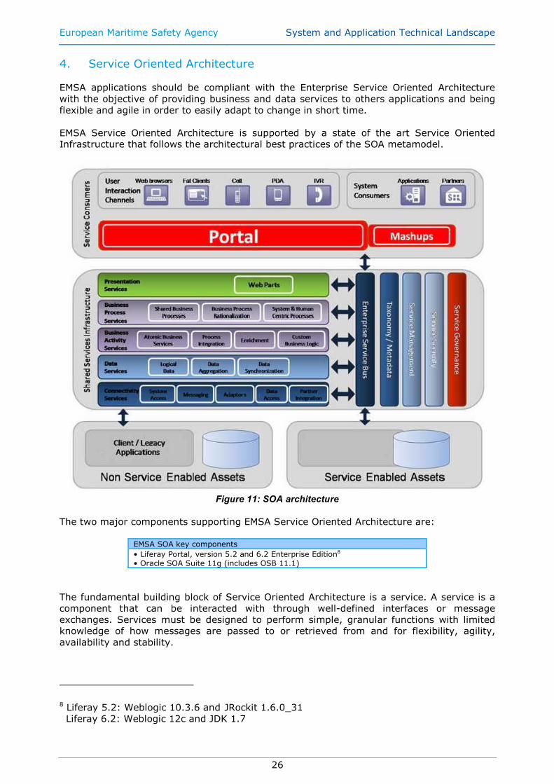
4. Service Oriented Architecture
EMSA applications should be compliant with the Enterprise Service Oriented Architecture
with the objective of providing business and data services to others applications and being
flexible and agile in order to easily adapt to change in short time.
EMSA Service Oriented Architecture is supported by a state of the art Service Oriented
Infrastructure that follows the architectural best practices of the SOA metamodel.
Figure 11: SOA architecture
The two major components supporting EMSA Service Oriented Architecture are:
EMSA SOA key components
• Liferay Portal, version 5.2 and 6.2 Enterprise Edition8 • Oracle SOA Suite 11g (includes OSB 11.1)
The fundamental building block of Service Oriented Architecture is a service. A service is a
component that can be interacted with through well-defined interfaces or message
exchanges. Services must be designed to perform simple, granular functions with limited
knowledge of how messages are passed to or retrieved from and for flexibility, agility,
availability and stability.
8 Liferay 5.2: Weblogic 10.3.6 and JRockit 1.6.0_31
Liferay 6.2: Weblogic 12c and JDK 1.7
European Maritime Safety Agency System and Application Technical Landscape
27
EMSA principles of service orientation, which must be followed while designing services,
are:
1. Services are loosely coupled components
2. Services are independent components
3. Services are self-contained
4. Services boundaries are explicit
5. Services are autonomous
6. Services share schema and contract
7. Services are independent deployable (logical aggregation can be considered)
Services designed based on these principles are much more likely to be reused within EMSA
growing SOA infrastructure.
4.1. SERVICE CONSUMERS
Service consumers or composite applications are the applications that are developed to
handle business actions or events initiated by business initiators. Business event initiators
are entities that initiate business actions or events (either human users or other systems).
4.2. SHARED SERVICE INFRASTRUCTURE
Shared service infrastructure defines the framework to shared services. It is based on
Validate, Enrich, Transform, Route, and Operate or invokes (VETRO) patterns
Shared services are shared and reusable services that are used in service orchestration
while creating business processes. Examples of shared services types are:
• Presentation services that present the data to the user.
• Business services that represent core business capabilities. Business services can
range from relatively simple to very complex cross-functional, inter-enterprise
business process.
• Data services that are entity services which provide access to enterprise data.
Simple data services have a Validate, Create, Retrieve, Update, and Delete (CRUD)
interface but more complex data services could be responsible for data aggregation
or data synchronization.
European Maritime Safety Agency System and Application Technical Landscape
28
5. LDAP Structure for Maritime Applications
5.1. LDAP STRUCTURE
The following figure provides an overview of the LDAP structure to be used for the different
Maritime applications:
Dc=emsa,dc=europa,dc=eu
Ou=Users
organizationalUnit
Ou=groups
organizationalUnit
Ou=People
organizationalUnit
Ou=System
organizationalUnit
Uid=John
Uid=Roger
Uid=sys1
Uid=sys2
Ou=App1
organizationalUnitOu=App2
organizationalUnit
Cn=Role1
groupOfNames
Cn=Role2
groupOfNamesCn=Members
groupOfName
Figure 12 - LDAP structure overview
In this first implementation stage, this LDAP shall provide authentication services for users
and systems and one first level of information to authorization services.
Domain Component
DC=emsa,DC=europa,DC=eu
OU=Users This Organizational Unit will contain all the users registered to access any of the Maritime Applications. See also chapter “Authentication service”
OU=People Human users will belong to this Organization Unit
OU=System Systems (non-human users) will belong to this Organization Unit
OU=Groups Information and groups stored below this OU will provide the first level of information to authorization services. See also chapter “Authorization service”
OU=App1 Organizational Unit for Maritime Application (or system) called App1. All users and systems with granted access to App1 are under this group.
OU=App2 Organizational Unit for Maritime Application (or system) called App2. All users and systems with granted access to App2 are under this group.
Table 1 - LDAP main elements
5.2. AUTHENTICATION SERVICE
Registered users are stored under OU=Users. A separation is made between Human Users
and System Users:
• Human Users are registered under OU=People, OU=Users
• System Users are registered under OU=System, OU=Users
European Maritime Safety Agency System and Application Technical Landscape
29
5.3. AUTHORIZATION SERVICES
Each Maritime Applications that must have its correspondent organizational unit under
OU=Groups. Registered Users that have privileges to access a specific application must be
member of that application to have access authorization granted.
Two different scenarios can be implemented:
1. Applications that requires only a global authorization
It is enough to know that access to the application has been granted to the user. In
this scenario, it is suggested to create a group of name called “members” under the
application organizational unit. All users authorized are members of this
“GroupOfNames”
2. Applications that requires roles/groups authorization
There is the need to know that access to the application has been granted to the
user and, in addition, what role/group does the user belong.
In this scenario, it is suggested to create several groups of names, one for each
role/group under the application organizational unit. Users are members of one or
more “GroupOfName”
European Maritime Safety Agency System and Application Technical Landscape
30
6. Software Versioning Scheme
All applications being developed for or by EMSA shall use the following versioning scheme:
• [major].[minor].[revision]<.internal number>
Follows a description of the fields:
• Major will start 0 and will be increased by 1 every time significant new functionality
is added to the application, or when significant changes to the implementation
and/or organisation of the code have happened, such as:
o When delivery of a new application or a major new version has been
accepted, the major number will be increased by 1, other version numbers
will be reset to 0;
o Development of the next major version starts by increasing major version
number by 1 and resetting all other version numbers to 0;
o The above rules mean that all even numbered versions (+0) will be
development releases for major new versions, whilst all odd numbered
versions will be stable, production releases. E.g. if a software with version
number 0.2.65 has been accepted for use in production environment, its
version number will be 1.0.0. Development for the next major release will
start at 2.0.0 and the production accepted release of this will carry a 3.0.0
version;
• Minor will be increased by 1 whenever less important new functionality or user
interface changes are introduced;
• Revision will be increased by 1 whenever a new application version containing only
bug fixes is delivered for deployment in EMSA pre-production environment;
• The internal number is an optional element that may be used by the contractor.
European Maritime Safety Agency System and Application Technical Landscape
31
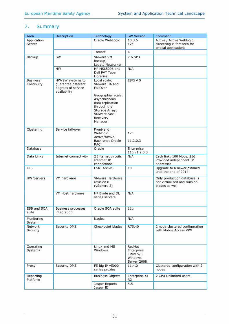
7. Summary Area Description Technology SW Version Comment
Application Server
Oracle WebLogic 10.3.6 12c
Active / Active Weblogic clustering is foreseen for critical applications
Tomcat 6
Backup SW VMware VM backup; Legato Networker
7.6 SP3
HW HP MSL8096 and Dell PVT Tape Libraries
N/A
Business Continuity
HW/SW systems to guarantee different degrees of service availability
Local scale: VMware HA and FailOver Geographial scale: Asynchronous data replication through the Storage Array; VMWare Site Recovery Manager;
ESXi V 5
Clustering Service fail-over Front-end: Weblogic Active/Active Back-end: Oracle RAC
12c 11.2.0.3
Database Oracle Enterprise 11g v1.2.0.3
Data Links Internet connectivity 2 Internet circuits Internet IP connections
N/A Each link: 100 Mbps, 256 Provided independent IP addresses
GIS ESRI ArcGIS 10 Upgrade to a newer planned until the end of 2014
HW Servers VM hardware VMware Hardware revision 8 (vSphere 5)
Only production database is not virtualised and runs on blades as well.
VM Host hardware HP Blade and DL series servers
N/A
ESB and SOA suite
Business processes integration
Oracle SOA suite 11g
Monitoring System
Nagios N/A
Network Security
Security DMZ Checkpoint blades R75.40 2 node clustered configuration with Mobile Access VPN
Operating Systems
Linux and MS Windows
RedHat Enterprise Linux 5/6 Windows Server 2008
Proxy Security DMZ F5 Big IP v5000 series proxies
11.4.0 Clustered configuration with 2 nodes
Reporting Platform
Business Objects Enterprise XI R2
2 CPU Unlimited users
Jasper Reports Jasper BI
5.5
European Maritime Safety Agency System and Application Technical Landscape
32
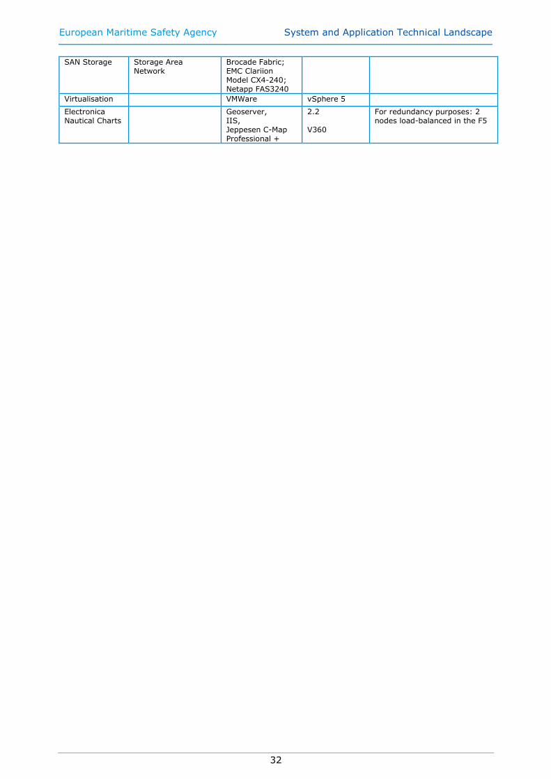
SAN Storage Storage Area Network
Brocade Fabric; EMC Clariion Model CX4-240; Netapp FAS3240
Virtualisation VMWare vSphere 5
Electronica Nautical Charts
Geoserver, IIS, Jeppesen C-Map Professional +
2.2 V360
For redundancy purposes: 2 nodes load-balanced in the F5

European Maritime Safety Agency System and Application Technical Landscape
33
Annex 1
GSSP (GIAC Secure Software Programmer) Java/Java EE Implementation Issues
www.sans.org
Task 1: Input Handling - Java programmers must be able to write programs that read input from their interfaces
and properly validate and process these inputs including command line arguments, environment variables, and input
streams. As these sources may ultimately derive from user input or other untrusted sources, Input Handling has
security repercussions.
01.1.1 Input Validation Principles - Java programmers must understand that input cannot be trusted, regardless of
the interface, i.e., HTTP Requests, Applet sockets, serialized streams, configuration files, backend datastores, etc.
Java programmers must understand the white-list approaches and black-list approaches and the tradeoffs between
them.
01.1.2 Input Validation Sources - Java programmers must recognize common sources of input to Java
applications. This enables them to know when to question the trust level of certain data and weigh it to decide if
input validation is warranted.
01.1.3 Input Validation Techniques - Java programmers must understand how to validate common data types
such as String data as well as uncommon input structures. Familiarity with Regular Expressions, doValidate() and
other tools of Java and J2EE to perform input validation are required.
Task 2: Authentication & Session Management - Java application programmers must have a basic
understanding of Java and J2EE authentication APIs as well as a mastery of authentication principles for
local and remote applications. For the purposes of this examination, Session Management is considered the
process of maintaining an end-user’s authenticated identity for an extended period. It is required that Java
programmers understand the threats to common authentication and session management operations in order
to properly protect these operations. 01.2.1 When to Authenticate - Java programmers must understand that authentication is needed not only for end-
users, but also 3rd party services, backend systems, etc.
01.2.2 Authentication Protection - Java programmers are required to know how to use encryption and certificates
to protect various authentication processes. This includes an understanding of strength-of-function, credential
expiration, credential recovery/reset, and re-authentication.
01.2.3 Session Protection. For the protection of session tokens, Java programmers are required to understand the
implications of several topics, including encryption, strength-of-function, lifespan of tokens, and re-issuance.
01.2.4 Rule 4: Authentication Techniques - Java programmers must be familiar with the more common
authentication techniques and APIs available within Java and J2EE technologies. This includes the Java
Authentication and Authorization Services (JAAS), backend credential storage, and various front-end authentication
alternatives such as certificate, forms, and basic authentication. This familiarity assumes the programmer will
understand the threats and tradeoffs for each technique.
01.2.5 Authentication Responsibilities - Java programmers must have a complete understanding of what services
and protections are provided by using common APIs and what is not provided. For example, maximum session
length, re-authentication, and encryption are protections that are not enabled automatically.
Task 3: Access Control (Authorization) - Java application programmers must be able develop applications
that guarantee the confidentiality of user data. These applications must also prevent users from performing
certain functions. Developers must understand that access control must actively be enforced, not ignored or
left to backend systems. 01.3.1 Restricting Access to Resources - Java developers must under-stand the need for a clear and complete
access control policy for system resources: for example, user data objects that should only be accessed by the owner
of the data.
01.3.2 Restricting Access to Functions - Java developers must understand the need to restrict access to functions
such as privileged functions and privileged URIs, etc.
01.3.3 Declarative Access Control - An understanding of the common APIs (and their tradeoffs) that supports
access control according to configuration files.
01.3.4 Programmatic Access Control - Java developers must understand how and when to manually perform
access control checks in their custom code.
01.3.5 JAAS - Java developers must understand how the Java Authentication and Authorization Service can be
used to implement access control.

European Maritime Safety Agency System and Application Technical Landscape
34
Task 4: Java Types & JVM Management - Java programmers must understand the security implications of
built-in data types and Java-specific memory management. 01.4.1 java.lang.String - Java programmers must have a complete mastery of the String class’s immutability and
how to compare String objects.
01.4.2 Integer and Double Overflows - Java programmers must understand the limitations of Java’s numerical
data types and the resulting security implications.
01.4.3 Garbage Collector - Java programmers must have an understanding of how the Java Garbage Collector
works and the resulting security implications.
01.4.4 ArrayList vs Vector - Java programmers must understand the differences and the resulting security
considerations between the ArrayList and the Vector.
01.4.5 Class Security - Java programmers should be familiar with accessibility modifiers, the final modifier, class
comparisons, serialization, clone-ability, and inner classes.
01.4.6 Code Privileges - Java Programmers must understand how to manage the privileges of code as well as the
different protection domains. This includes an understanding of the Security Manager and its policy file.
Task 5: Application Faults & Logging - All Java application programmers need to be able to properly handle
application faults. 01.5.1 Exception Handling - Java application developers must understand Java’s try/catch/finally construct to
appropriately handle application and system exceptions. Developers must determine how much information should
be logged when an exception is encountered depending on the nature of the exception.
01.5.2 Logging - Developers must understand the principles behind logging security-relevant events such as login,
logoff, credential changes, etc. Developers should also be familiar with Java’s logging package, java.util.logging.
01.5.3 Configuration of Error Handling - J2EE developers should be familiar with the configuration to return a
default error page for HTTP 404 and 500 errors.
Task 6: Encryption Services - Java programmers must understand when and how to use encryption to
protect sensitive data. 01.6.1 Communications Encryption - Java application developers must be familiar with the Java Secure Sockets
Extension (JSSE) packages as well as how to configure SSL communication for J2EE applications. Developers are
also responsible for knowing which of their application’s external links should be protected with encryption.
01.6.2 Encryption of Data at Rest - Java developers must understand how to store sensitive data in encrypted
format.
Task 7: Concurrency and Threading - Java programmers must understand how to properly structure multi-
threaded programs. 01.7.1 Race Conditions - All Java application developers must understand race conditions and how they affect
system security. This includes avoiding caching security relevant information that can be accessed by multiple
threads.
01.7.2 Singletons & Shared Resources - Java developers must understand how to implement the Singleton pattern
in Java and how to protect other resources that are accessed by multiple threads.
Task 8: Connection Patterns - Java programs must be able to securely interface with other applications.
Developers must be familiar with parameterized queries, output encoding, and fail-safe connection patterns. 01.8.1 Parameterized Queries / PreparedStatements - Java programmers must understand the security risks
introduced by using dynamic queries and how to safely use the PreparedStatement to safely and securely interact
with databases based on user-supplied input.
01.8.2 Output Encoding - Java programmers must understand when and how to use output encoding to display data
to user interfaces, as this is a primary mitigation technique to UI injection attacks, e.g. Cross-site Scripting.
01.8.3 Fail-safe Connection Patterns - Java programmers must properly form connection patterns using Java’s
try/catch/finally to prevent resource leaks. Resource leaks can occur as a result of failures while operating with
connections to external systems.
Task 9: Miscellaneous 01.9.1 Class/Package/Method Access Modifiers - All Java programmers must understand how the Java access
modifiers (public, private, protected) can be used to protect class members and methods.
01.9.2 Class File Protection - Java programmers must understand how JAR sealing is used.
01.9.3 J2EE Filters - J2EE programmers must be familiar with J2EE Filters and how they can be used to implement
many of the tasks listed above.


![Dl-reamer Technical Presentation External[2]](https://static.fdocuments.net/doc/165x107/577cb4901a28aba7118c8803/dl-reamer-technical-presentation-external2.jpg)