
System Administration Guide: Devices and File Systems
470
System Administration Guide: Devices and File Systems Sun Microsystems, Inc. 4150 Network Circle Santa Clara, CA 95054 U.S.A. Part No: 817–6960–11 September 2004
Transcript of System Administration Guide: Devices and File Systems

System Administration Guide:Devices and File Systems
Sun Microsystems, Inc.4150 Network CircleSanta Clara, CA 95054U.S.A.
Part No: 817–6960–11September 2004

Copyright 2004 Sun Microsystems, Inc. 4150 Network Circle, Santa Clara, CA 95054 U.S.A. All rights reserved.
This product or document is protected by copyright and distributed under licenses restricting its use, copying, distribution, and decompilation. Nopart of this product or document may be reproduced in any form by any means without prior written authorization of Sun and its licensors, if any.Third-party software, including font technology, is copyrighted and licensed from Sun suppliers.
Parts of the product may be derived from Berkeley BSD systems, licensed from the University of California. UNIX is a registered trademark in the U.S.and other countries, exclusively licensed through X/Open Company, Ltd.
Sun, Sun Microsystems, the Sun logo, docs.sun.com, AnswerBook, AnswerBook2, JumpStart, Sun Ray, Sun Blade, PatchPro, SunOS, Solstice, SolsticeAdminSuite, Solstice DiskSuite, Solaris Solve, Java, JavaStation, OpenWindows, NFS, iPlanet, Netra and Solaris are trademarks or registeredtrademarks of Sun Microsystems, Inc. in the U.S. and other countries. All SPARC trademarks are used under license and are trademarks or registeredtrademarks of SPARC International, Inc. in the U.S. and other countries. Products bearing SPARC trademarks are based upon an architecturedeveloped by Sun Microsystems, Inc. X/Open is a registered trademark of X/Open Company, Ltd. DLT is claimed as a trademark of QuantumCorporation in the United States and other countries.
The OPEN LOOK and Sun™ Graphical User Interface was developed by Sun Microsystems, Inc. for its users and licensees. Sun acknowledges thepioneering efforts of Xerox in researching and developing the concept of visual or graphical user interfaces for the computer industry. Sun holds anon-exclusive license from Xerox to the Xerox Graphical User Interface, which license also covers Sun’s licensees who implement OPEN LOOK GUIsand otherwise comply with Sun’s written license agreements.
U.S. Government Rights – Commercial software. Government users are subject to the Sun Microsystems, Inc. standard license agreement andapplicable provisions of the FAR and its supplements.
DOCUMENTATION IS PROVIDED “AS IS” AND ALL EXPRESS OR IMPLIED CONDITIONS, REPRESENTATIONS AND WARRANTIES,INCLUDING ANY IMPLIED WARRANTY OF MERCHANTABILITY, FITNESS FOR A PARTICULAR PURPOSE OR NON-INFRINGEMENT, AREDISCLAIMED, EXCEPT TO THE EXTENT THAT SUCH DISCLAIMERS ARE HELD TO BE LEGALLY INVALID.
Copyright 2004 Sun Microsystems, Inc. 4150 Network Circle, Santa Clara, CA 95054 U.S.A. Tous droits réservés.
Ce produit ou document est protégé par un copyright et distribué avec des licences qui en restreignent l’utilisation, la copie, la distribution, et ladécompilation. Aucune partie de ce produit ou document ne peut être reproduite sous aucune forme, par quelque moyen que ce soit, sansl’autorisation préalable et écrite de Sun et de ses bailleurs de licence, s’il y en a. Le logiciel détenu par des tiers, et qui comprend la technologie relativeaux polices de caractères, est protégé par un copyright et licencié par des fournisseurs de Sun.
Des parties de ce produit pourront être dérivées du système Berkeley BSD licenciés par l’Université de Californie. UNIX est une marque déposée auxEtats-Unis et dans d’autres pays et licenciée exclusivement par X/Open Company, Ltd.
Sun, Sun Microsystems, le logo Sun, docs.sun.com, AnswerBook, AnswerBook2, JumpStart, Sun Ray, Sun Blade, PatchPro, SunOS, Solstice, SolsticeAdminSuite, Solstice DiskSuite, Solaris Solve, Java, JavaStation, DeskSet, OpenWindows, NFS et Solaris sont des mardques de fabrique ou desmarques déposées, de Sun Microsystems, Inc. aux Etats-Unis et dans d’autres pays. Toutes les marques SPARC sont utilisées sous licence et sont desmarques de fabrique ou des marques déposées de SPARC International, Inc. aux Etats-Unis et dans d’autres pays. Les produits portant les marquesSPARC sont basés sur une architecture développée par Sun Microsystems, Inc. X/Open est une marque de fabrique ou une marque d?pos?e deX/Open Company, Ltd. Quantum Corporation riclame DLT comme sa marque de fabrique aux Etats-Unis et dans d’autres pays.
L’interface d’utilisation graphique OPEN LOOK et Sun™ a été développée par Sun Microsystems, Inc. pour ses utilisateurs et licenciés. Sun reconnaîtles efforts de pionniers de Xerox pour la recherche et le développement du concept des interfaces d’utilisation visuelle ou graphique pour l’industriede l’informatique. Sun détient une licence non exclusive de Xerox sur l’interface d’utilisation graphique Xerox, cette licence couvrant également leslicenciés de Sun qui mettent en place l’interface d’utilisation graphique OPEN LOOK et qui en outre se conforment aux licences écrites de Sun.
CETTE PUBLICATION EST FOURNIE “EN L’ETAT” ET AUCUNE GARANTIE, EXPRESSE OU IMPLICITE, N’EST ACCORDEE, Y COMPRIS DESGARANTIES CONCERNANT LA VALEUR MARCHANDE, L’APTITUDE DE LA PUBLICATION A REPONDRE A UNE UTILISATIONPARTICULIERE, OU LE FAIT QU’ELLE NE SOIT PAS CONTREFAISANTE DE PRODUIT DE TIERS. CE DENI DE GARANTIE NES’APPLIQUERAIT PAS, DANS LA MESURE OU IL SERAIT TENU JURIDIQUEMENT NUL ET NON AVENU.
040727@9495
Contents
Preface 19
1 Managing Removable Media (Overview) 23
Where to Find Managing Removable Media Tasks 23
Removable Media Features and Benefits 24
Comparison of Automatic and Manual Mounting 24
What You Can Do With Volume Management 25
2 Accessing Removable Media (Tasks) 27
Accessing Removable Media (Task Map) 27
Accessing Removable Media (Overview) 28
Using Removable Media Names 28
Guidelines for Accessing Removable Media Data 30
� How to Add a New Removable Media Drive 30
Stopping and Starting Volume Management (vold) 31
� How to Access Information on Removable Media 32
� How to Copy Information From Removable Media 33
� How to Play a Musical CD or DVD 33
� How to Find Out If Removable Media Is Still in Use 34
� How to Eject Removable Media 35
Accessing Removable Media on a Remote System (Task Map) 36
� How to Make Local Media Available to Other Systems 36
� How to Access Removable Media on Remote Systems 39
3

3 Formatting Removable Media (Tasks) 43Formatting Removable Media (Task Map) 43Formatting Removable Media Overview 44
Formatting Removable Media Guidelines 44Removable Media Hardware Considerations 45� How to Load a Removable Media 46� How to Format Removable Media (rmformat) 48� How to Format Removable Media for Adding a File System 49� How to Check a File System on Removable Media 50� How to Repair Bad Blocks on Removable Media 51Applying Read or Write and Password Protection to Removable Media 51� How to Enable or Disable Write Protection on Removable Media 52� How to Enable or Disable Read or Write Protection and a Password on IomegaMedia 52
4 Writing CDs (Tasks) 55
Working with Audio and Data CDs 55CD Media Commonly Used Terms 56
Writing Data and Audio CDs 57Restricting User Access to Removable Media with RBAC 58� How to Restrict User Access to Removable Media with RBAC 58How to Identify a CD Writer 58� How to Check the CD Media 59Creating a Data CD 60� How to Create an ISO 9660 File System for a Data CD 60� How to Create a Multi-Session Data CD 61Creating an Audio CD 62� How to Create an Audio CD 63� How to Extract an Audio Track on a CD 64� How to Copy a CD 65� How to Erase CD-RW Media 65
5 Managing Devices (Tasks) 67
What’s New in Device Management? 67USB Device Enhancements 68
Where to Find Device Management Tasks 68About Device Drivers 68Automatic Configuration of Devices 69
4 System Administration Guide: Devices and File Systems • September 2004

Features and Benefits of Autoconfiguration 70What You Need for Unsupported Devices 70
Displaying Device Configuration Information 71driver not attached Message 71Identifying a System’s Devices 72How to Display System Configuration Information 72How to Display Device Information 74
Adding a Peripheral Device to a System 75� How to Add a Peripheral Device 75� How to Add a Device Driver 76
6 Dynamically Configuring Devices (Tasks) 79
Dynamic Reconfiguration and Hot-Plugging 79Attachment Points 80x86: Detaching PCI Adapter Cards 82
SCSI Hot-Plugging With the cfgadm Command (Task Map) 83SCSI Hot-Plugging With the cfgadm Command 84
� How to Display Information About SCSI Devices 84� How to Unconfigure a SCSI Controller 85� How to Configure a SCSI Controller 85� How to Configure a SCSI Device 86� How to Disconnect a SCSI Controller 87� SPARC: How to Connect a SCSI Controller 88� SPARC: How to Add a SCSI Device to a SCSI Bus 88� SPARC: How to Replace an Identical Device on a SCSI Controller 89� SPARC: How to Remove a SCSI Device 90SPARC: Troubleshooting SCSI Configuration Problems 91� How to Resolve a Failed SCSI Unconfigure Operation 93
PCI Hot-Plugging With the cfgadm Command (Task Map) 93x86: PCI Hot-Plugging With the cfgadm Command 94
� x86: How to Display PCI Slot Configuration Information 94� x86: How to Remove a PCI Adapter Card 95� x86: How to Add a PCI Adapter Card 96x86: Troubleshooting PCI Configuration Problems 97
Reconfiguration Coordination Manager (RCM) Script Overview 97What Is an RCM Script? 98What Can an RCM Script Do? 98How Does the RCM Script Process Work? 98
5

RCM Script Tasks 99Application Developer RCM Script (Task Map) 100System Administrator RCM Script (Task Map) 100Naming an RCM Script 101Installing or Removing an RCM Script 101� How to Install an RCM Script 102� How to Remove an RCM Script 102� How to Test an RCM Script 102Tape Backup RCM Script Example 103
7 Using USB Devices (Overview) 107
What’s New in USB Devices? 107USB Dual Framework 107Solaris Support for USB Devices 108SPARC: USB 2.0 Features 110USB Mass Storage Devices 112SPARC: USB Driver Enhancements 113
Overview of USB Devices 114Commonly Used USB Acronyms 115USB Bus Description 115
About USB in the Solaris Environment 118USB Keyboards and Mouse Devices 118USB Host Controller and Root Hub 119SPARC: USB Power Management 120Guidelines for USB Cables 121
8 Using USB Devices (Tasks) 123
Managing USB Devices in the Solaris Environment (Roadmap) 123Using USB Mass Storage Devices (Task Map) 124
Using USB Mass Storage Devices 125Preparing to Use a USB Mass Storage Device With vold Running 126� How to Prepare to Use USB Mass Storage Devices Without vold Running 127How to Display USB Device Information (prtconf) 128� How to Format a USB Mass Storage Device Without vold Running 129� How to Mount or Unmount a USB Mass Storage Device With voldRunning 131� How to Mount or Unmount a USB Mass Storage Device Without voldRunning 132
6 System Administration Guide: Devices and File Systems • September 2004

Disabling Specific USB Drivers 133� How to Disable Specific USB Drivers 133� How to Remove Unused USB Device Links 134
Hot-Plugging USB Devices (Task Map) 134� How to Add a USB Mass Storage Device With vold Running 135� How to Add a USB Mass Storage Device Without vold Running 136� How to Remove a USB Mass Storage Device With vold Running 136� How to Remove a USB Mass Storage Device Without vold Running 137� How to Add a USB Camera 137
Using USB Audio Devices (Task Map) 139Using USB Audio Devices 139Hot-Plugging Multiple USB Audio Devices 140� How to Add USB Audio Devices 141� How to Identify Your System’s Primary Audio Device 141How to Change the Primary USB Audio Device 142Troubleshooting USB Audio Device Problems 142
Hot-Plugging USB Devices With the cfgadm Command (Task Map) 143Hot-Plugging USB Devices With the cfgadm Command 144How to Display USB Bus Information (cfgadm) 145� How to Unconfigure a USB Device 146� How to Configure a USB Device 146� How to Logically Disconnect a USB Device 146� How to Logically Connect a USB Device 147� How to Logically Disconnect a USB Device Subtree 147� How to Reset a USB Device 148� How to Change the Default Configuration of a Multi-Configuration USBDevice 148
9 Accessing Devices (Overview) 151
Accessing Devices 151How Device Information Is Created 151How Devices Are Managed 152Device Naming Conventions 152
Logical Disk Device Names 153Specifying the Disk Subdirectory 153Specifying the Slice 154x86: Disks With Direct Controllers 154SPARC: Disks With Bus-Oriented Controllers 155
7

x86: Disks With SCSI Controllers 155
Logical Tape Device Names 156
Logical Removable Media Device Names 157
10 Managing Disks (Overview) 159
What’s New in Disk Management in the Solaris 9 Update Releases? 159
SPARC: Multiterabyte Disk Support With EFI Disk Label 159
Where to Find Disk Management Tasks 164
Overview of Disk Management 164
Disk Terminology 164
About Disk Slices 165
SPARC: Disk Slices 166
x86: Disk Slices 167
Using Raw Data Slices 169
Slice Arrangements on Multiple Disks 169
Determining Which Slices to Use 170
The format Utility 170
When to Use the format Utility 171
Guidelines for Using the format Utility 172
Formatting a Disk 173
About Disk Labels 174
Partition Table 174
Displaying Partition Table Information 175
Dividing a Disk Into Slices 176
Using the Free Hog Slice 177
11 Administering Disks (Tasks) 179
Administering Disks (Task Map) 179
Identifying Disks on a System 180
� How to Identify the Disks on a System 180
Formatting a Disk 182
� How to Determine if a Disk is Formatted 182
� How to Format a Disk 183
Displaying Disk Slices 185
� How to Display Disk Slice Information 185
Creating and Examining a Disk Label 187
� How to Label a Disk 187
8 System Administration Guide: Devices and File Systems • September 2004

� How to Examine a Disk Label 189Recovering a Corrupted Disk Label 190
� How to Recover a Corrupted Disk Label 191Adding a Third-Party Disk 193
Creating a format.dat Entry 194� How to Create a format.dat Entry 194
Automatically Configuring SCSI Disk Drives 194� How to Automatically Configure a SCSI Drive 195
Repairing a Defective Sector 197� How to Identify a Defective Sector by Using Surface Analysis 197� How to Repair a Defective Sector 198
Tips and Tricks for Managing Disks 199Debugging format Sessions 199Label Multiple Disks by Using the prtvtoc and fmthard Commands 200
12 SPARC: Adding a Disk (Tasks) 201
SPARC: Adding a System Disk or a Secondary Disk (Task Map) 201SPARC: Adding a System Disk or a Secondary Disk 202� SPARC: How to Connect a System Disk and Boot 202� SPARC: How to Connect a Secondary Disk and Boot 203� SPARC: How to Create Disk Slices and Label a Disk 204� SPARC: How to Create a UFS File System 209� SPARC: How to Install a Boot Block on a System Disk 209
13 x86: Adding a Disk (Tasks) 211
x86: Adding a System Disk or a Secondary Disk (Task Map) 211x86: Adding a System or Secondary Disk 212
� x86: How to Connect a System Disk and Boot 212� x86: How to Connect a Secondary Disk and Boot 213x86: Guidelines for Creating an fdisk Partition 214� x86: How to Create a Solaris fdisk Partition 215� x86: How to Create Disk Slices and Label a Disk 220� x86: How to Create File Systems 222� x86: How to Install a Boot Block on a System Disk 222
14 The format Utility (Reference) 225
Recommendations and Requirements for Using The format Utility 225
9

Format Menu and Command Descriptions 226The partition Menu 228x86: The fdisk Menu 228The analyze Menu 229The defect Menu 231
The format.dat File 232Contents of the format.dat File 232Syntax of the format.dat File 233Keywords in the format.dat File 233Partition or Slice Tables (format.dat) 235Specifying an Alternate Data File for the format utility 236
Rules for Input to format Commands 237Specifying Numbers to format Commands 237Specifying Block Numbers to format Commands 237Specifying format Command Names 238Specifying Disk Names to format Commands 238
Getting Help on the format Utility 239
15 Managing File Systems (Overview) 241
What’s New in File Systems in the Solaris 9 Update Releases? 241UFS Logging Is Enabled by Default 241SPARC: Support of Multiterabyte UFS File Systems 243
Where to Find File System Management Tasks 249Overview of File Systems 249Types of File Systems 250
Disk-Based File Systems 250Network-Based File Systems 251Virtual File Systems 251Extended File Attributes 254
Commands for File System Administration 255How File System Commands Determine the File System Type 256Manual Pages for Generic and Specific Commands 256
The Default Solaris File Systems 256Swap Space 258The UFS File System 258
Planning UFS File Systems 258UFS Logging 259UFS Snapshots 260
10 System Administration Guide: Devices and File Systems • September 2004

UFS Direct Input/Output (I/O) 260
Mounting and Unmounting File Systems 261
The Mounted File System Table 262
The Virtual File System Table 263
The NFS Environment 264
Automounting or AutoFS 264
Determining a File System’s Type 265
How to Determine a File System’s Type 265
16 Creating UFS, TMPFS, and LOFS File Systems (Tasks) 267
Creating a UFS File System 267
Default Parameters for the newfs Command 268
� How to Create a UFS File System 268
Creating a Temporary File System (TMPFS) 270
� How to Create a TMPFS File System 270
Creating a Loopback File System (LOFS) 271
� How to Create an LOFS File System 272
17 Mounting and Unmounting File Systems (Tasks) 275
Overview of Mounting File Systems 275
Commands for Mounting and Unmounting File Systems 276
Commonly Used Mount Options 277
Field Descriptions for the /etc/vfstab File 278
Mounting File Systems 280
How to Determine Which File Systems Are Mounted 280
� How to Add an Entry to the /etc/vfstab File 281
� How to Mount a File System (/etc/vfstab File) 282
� How to Mount a UFS File System (mount Command) 283
� How to Mount a UFS File System Without Large Files (mount Command) 284
� How to Mount an NFS File System (mount Command) 285
� x86: How to Mount a PCFS (DOS) File System From a Hard Disk (mountCommand) 286
Unmounting File Systems 287
Prerequisites for Unmounting File Systems 287
How to Verify a File System is Unmounted 288
� How to Stop All Processes Accessing a File System 288
� How to Unmount a File System 289
11

18 Using The CacheFS File System (Tasks) 291
High-Level View of Using the CacheFS File System (Task Map) 291
Overview of the CacheFS File System 292
How a CacheFS File System Works 292
CacheFS File System Structure and Behavior 293
Creating and Mounting a CacheFS File System (Task Map) 294
� How to Create the Cache 295
Mounting a File System in the Cache 295
� How to Mount a CacheFS File System (mount) 296
� How to Mount a CacheFS File System (/etc/vfstab) 298
� How to Mount a CacheFS File System (AutoFS) 299
Maintaining a CacheFS File System (Task Map) 299
Maintaining a CacheFS File System 300
Modifying a CacheFS File System 300
� How to Display Information About a CacheFS File System 301
Consistency Checking of a CacheFS File System 302
� How to Specify Cache Consistency Checking on Demand 302
� How to Delete a CacheFS File System 302
� How to Check the Integrity of a CacheFS File System 304
Packing a Cached File System (Task Map) 305
Packing a CacheFS File System 305
How to Pack Files in the Cache 306
How to Display Packed Files Information 307
Using Packing Lists 308
How to Create a Packing List 308
How to Pack Files in the Cache With a Packing List 309
Unpacking Files or Packing Lists From the Cache 309
How to Unpack Files or Packing Lists From the Cache 309
Troubleshooting cachefspack Errors 310
Collecting CacheFS Statistics (Task Map) 314
Collecting CacheFS Statistics 314
� How to Set Up CacheFS Logging 316
How to Locate the CacheFS Log File 316
How to Stop CacheFS Logging 317
� How to View the Working Set (Cache) Size 317
Viewing CacheFS Statistics 318
How to View CacheFS Statistics 318
12 System Administration Guide: Devices and File Systems • September 2004

19 Configuring Additional Swap Space (Tasks) 321
About Swap Space 321
Swap Space and Virtual Memory 322
Swap Space and the TMPFS File System 322
Swap Space as a Dump Device 323
Swap Space and Dynamic Reconfiguration 323
How Do I Know If I Need More Swap Space? 324
Swap-Related Error Messages 324
TMPFS-Related Error Messages 324
How Swap Space Is Allocated 325
The /etc/vfstab File 325
Planning for Swap Space 325
Monitoring Swap Resources 326
Adding More Swap Space 327
Creating a Swap File 328
� How to Create a Swap File and Make It Available 328
Removing a Swap File From Use 329
� How to Remove Unneeded Swap Space 329
20 Checking UFS File System Consistency (Tasks) 331
File System Consistency 332
How the File System State Is Recorded 332
What the fsck Command Checks and Tries to Repair 333
Why Inconsistencies Might Occur 334
The UFS Components That Are Checked for Consistency 334
The fsck Summary Message 339
Interactively Checking and Repairing a UFS File System 340
� How to Check the root (/) or /usr File Systems From an Alternate BootDevice 341
� How to Check Non-root (/) or Non-/usr File Systems 343
Preening UFS File Systems 344
� How to Preen a UFS File System 345
Fixing a UFS File System That the fsck Command Cannot Repair 345
Restoring a Bad Superblock 346
� How to Restore a Bad Superblock 346
Syntax and Options for the fsck Command 348
13

21 UFS File System (Reference) 349
Default Directories for root (/) and /usr File Systems 349The Platform-Dependent Directories 357The Structure of Cylinder Groups for UFS File Systems 357
The Boot Block 358The Superblock 358Inodes 358Data Blocks 360Free Blocks 360
Custom File System Parameters 361Logical Block Size 361Fragment Size 362Minimum Free Space 362Rotational Delay 363Optimization Type 363Number of Inodes (Files) 363Maximum UFS File and File System Size 364Maximum Number of UFS Subdirectories 364
Commands for Creating a Customized File System 364The newfs Command Syntax, Options, and Arguments 364The Generic mkfs Command 368
22 Backing Up and Restoring File Systems (Overview) 369
Where to Find Backup and Restore Tasks 369Definition: Backing Up and Restoring File Systems 370Why You Should Back Up File Systems 371Planning Which File Systems to Back Up 371Choosing the Type of Backup 373Choosing a Tape Device 374High-Level View of Backing Up and Restoring File Systems (Task Map) 374Guidelines for Scheduling Backups 375
How Often Should You Do Backups? 375Backup Terms and Definitions 376Suggestions for Scheduling Backups 376Using Dump Levels to Create Incremental Backups 378
Sample Backup Schedules 379Example—Daily Cumulative, Weekly Cumulative Backups 379Example—Daily Cumulative, Weekly Incremental Backups 380
14 System Administration Guide: Devices and File Systems • September 2004
Example—Daily Incremental, Weekly Cumulative Backups 381Example—Monthly Backup Schedule for a Server 382
23 Backing Up Files and File Systems (Tasks) 387
Backing Up Files and File System (Task Map) 387Preparing for File System Backups 388
� How to Find File System Names 388� How to Determine the Number of Tapes Needed for a Full Backup 389
Backing Up a File System 389� How to Backup a File System to Tape 390
24 Using UFS Snapshots (Tasks) 397
Using UFS Snapshots (Task Map) 397UFS Snapshots Overview 398
Why Use UFS Snapshots? 398UFS Snapshots Performance Issues 399
Creating and Deleting UFS Snapshots 399� How to Create a UFS Snapshot 400� How to Display UFS Snapshot Information 401Deleting a UFS Snapshot 402� How to Delete a UFS Snapshot 402
Backing Up a UFS Snapshot 403� How to Create a Full Backup of a UFS Snapshot (ufsdump) 403� How to Create an Incremental Backup of a UFS Snapshot (ufsdump) 404� How to Back Up a UFS Snapshot (tar) 404Restoring Data From a UFS Snapshot Backup 405
25 Restoring Files and File Systems (Tasks) 407
Restoring Files and File System Backups (Task Map) 407Preparing to Restore Files and File Systems 408
Determining the File System Name 409Determining the Type of Tape Device You Need 409Determining the Tape Device Name 409
Restoring Files and File Systems 409� How to Determine Which Tapes to Use 410� How to Restore Files Interactively 411� How to Restore Specific Files Noninteractively 413
15

� How to Restore a Complete File System 415
� How to Restore the root (/) and /usr File Systems 418
26 UFS Backup and Restore Commands (Reference) 421
How the ufsdump Command Works 421
Determining Device Characteristics 421
Detecting the End of Media 422
Copying Data With the ufsdump Command 422
Purpose of the /etc/dumpdates File 422
Backup Device (dump-file) Argument 423
Specifying Files to Back Up 425
Specifying Tape Characteristics 425
Limitations of the ufsdump Command 425
Options and Arguments for the ufsdump Command 426
Default ufsdump Options 426
Options for the ufsdump Command 426
The ufsdump Command and Security Issues 428
Options and Arguments for the ufsrestore Command 429
27 Copying UFS Files and File Systems (Tasks) 433
Commands for Copying File Systems 433
Copying File Systems Between Disks 434
Making a Literal File System Copy 435
� How to Copy a Disk (dd) 435
Copying Directories Between File Systems (cpio Command) 438
� How to Copy Directories Between File Systems (cpio) 438
Copying Files and File Systems to Tape 439
Copying Files to Tape (tar Command) 441
� How to Copy Files to a Tape (tar) 441
� How to List the Files on a Tape (tar) 442
� How to Retrieve Files From a Tape (tar) 442
Copying Files to a Tape With the pax Command 444
� How to Copy Files to a Tape (pax) 444
Copying Files to Tape With the cpio Command 445
� How to Copy All Files in a Directory to a Tape (cpio) 445
� How to List the Files on a Tape (cpio) 446
� How to Retrieve All Files From a Tape (cpio) 447
16 System Administration Guide: Devices and File Systems • September 2004

� How to Retrieve Specific Files From a Tape (cpio) 448
Copying Files to a Remote Tape Device 449
� How to Copy Files to a Remote Tape Device (tar and dd) 449
� How to Extract Files From a Remote Tape Device 450
Copying Files and File Systems to Diskette 451
What You Should Know When Copying Files to Diskettes 451
� How to Copy Files to a Single Formatted Diskette (tar) 452
� How to List the Files on a Diskette (tar) 453
� How to Retrieve Files From a Diskette (tar) 453
How to Archive Files to Multiple Diskettes 454
28 Managing Tape Drives (Tasks) 455
Choosing Which Media to Use 455
Backup Device Names 456
Specifying the Rewind Option for a Tape Drive 457
Specifying Different Densities for a Tape Drive 458
Displaying Tape Drive Status 458
� How to Display Tape Drive Status 458
Handling Magnetic Tape Cartridges 459
How to Retension a Magnetic Tape Cartridge 459
How to Rewind a Magnetic Tape Cartridge 460
Guidelines for Drive Maintenance and Media Handling 460
Index 461
17

18 System Administration Guide: Devices and File Systems • September 2004

Preface
System Administration Guide: Devices and File Systems is part of a set that includes asignificant part of the Solaris™ system administration information. This guidecontains information for both SPARC® based and x86 based systems.
This book assumes you have completed the following tasks:
� Installed the SunOS 5.9 operating system� Set up all the networking software that you plan to use
The SunOS 5.9 operating system is part of the Solaris product family, which alsoincludes many features, including the Solaris Common Desktop Environment (CDE).The SunOS 5.9 operating system is compliant with AT&T’s System V, Release 4operating system.
For the Solaris 9 release, new features interesting to system administrators are coveredin sections called What’s New in ... ? in the appropriate chapters.
Note – The Solaris operating system runs on two types of hardware, or platforms,SPARC and x86. The Solaris operating system runs on both 64–bit and 32–bit addressspaces. The information in this document pertains to both platforms and addressspaces unless called out in a special chapter, section, note, bullet, figure, table,example, or code example.
Note – Sun is not responsible for the availability of third-party Web sites mentioned inthis document. Sun does not endorse and is not responsible or liable for any content,advertising, products, or other materials that are available on or through such sites orresources. Sun will not be responsible or liable for any actual or alleged damage orloss caused by or in connection with the use of or reliance on any such content, goods,or services that are available on or through such sites or resources.
19

Who Should Use This BookThis book is intended for anyone responsible for administering one or more systemsrunning the Solaris 9 release. To use this book, you should have 1-2 years of UNIX®
system administration experience. Attending UNIX system administration trainingcourses might be helpful.
How the System AdministrationVolumes Are OrganizedHere is a list of the topics that are covered by the volumes of the SystemAdministration Guides.
Book Title Topics
System Administration Guide: Basic Administration User accounts and groups, server and client support,shutting down and booting a system, and managingsoftware (packages and patches)
System Administration Guide: Advanced Administration Printing services, terminals and modems, systemresources (disk quotas, accounting, and crontabs),system processes, and troubleshooting Solaris softwareproblems
System Administration Guide: Devices and File Systems Removable media, disks and devices, file systems, andbacking up and restoring data
System Administration Guide: IP Services TCP/IP networks, IPv4 and IPv6, DHCP, IP Security,Mobile IP, IP Network Multipathing, and IPQoS
System Administration Guide: Naming and DirectoryServices (DNS, NIS, and LDAP)
DNS, NIS, and LDAP naming and directory services
System Administration Guide: Naming and DirectoryServices (FNS and NIS+)
NIS+ naming and directory services
System Administration Guide: Security Services Auditing, device management, file security, BART,PAM, Solaris cryptographic framework, privileges,RBAC, SASL, Solaris Secure Shell, and SEAM
System Administration Guide: Resource Management andNetwork Services
Resource management, remote file systems, mail, SLP,and PPP
20 System Administration Guide: Devices and File Systems • September 2004

Accessing Sun Documentation OnlineThe docs.sun.comSM Web site enables you to access Sun technical documentationonline. You can browse the docs.sun.com archive or search for a specific book title orsubject. The URL is http://docs.sun.com.
What Typographic Conventions MeanThe following table describes the typographic conventions used in this book.
TABLE P–1 Typographic Conventions
Typeface or Symbol Meaning Example
AaBbCc123 The names of commands, files, anddirectories; on-screen computer output
Edit your .login file.
Use ls -a to list all files.
machine_name% you havemail.
AaBbCc123 What you type, contrasted withon-screen computer output
machine_name% suPassword:
AaBbCc123 Command-line placeholder: replace witha real name or value
To delete a file, type rmfilename.
AaBbCc123 Book titles, new words or terms, orwords to be emphasized.
Read Chapter 6 in User’s Guide.
These are called class options.
Do not save changes yet.
Shell Prompts in Command ExamplesThe following table shows the default system prompt and superuser prompt for the Cshell, Bourne shell, and Korn shell.
21

TABLE P–2 Shell Prompts
Shell Prompt
C shell prompt machine_name%
C shell superuser prompt machine_name#
Bourne shell and Korn shell prompt $
Bourne shell and Korn shell superuser prompt #
General ConventionsBe aware of the following conventions used in this book.
� When following steps or using examples, be sure to type double-quotes ("), leftsingle-quotes (‘), and right single-quotes (’) exactly as shown.
� The key referred to as Return is labeled Enter on some keyboards.
� The root path usually includes the /sbin, /usr/sbin, /usr/bin, and /etcdirectories, so the steps in this book show the commands in these directorieswithout absolute path names. Steps that use commands in other, less common,directories show the absolute paths in the examples.
� The examples in this book are for a basic SunOS software installation without theBinary Compatibility Package installed and without /usr/ucb in the path.
Caution – If /usr/ucb is included in a search path, it should always be at the endof the search path. Commands like ps or df are duplicated in /usr/ucb withdifferent formats and options from the SunOS commands.
22 System Administration Guide: Devices and File Systems • September 2004
CHAPTER 1
Managing Removable Media(Overview)
This chapter provides general guidelines for managing removable media in the Solarisenvironment.
This is a list of the overview information in this chapter.
� “Where to Find Managing Removable Media Tasks” on page 23� “Removable Media Features and Benefits” on page 24� “Comparison of Automatic and Manual Mounting” on page 24� “What You Can Do With Volume Management” on page 25
Where to Find Managing RemovableMedia TasksUse these references to find step-by-step instructions for managing removable media.
Removable Media Management Task For More Information
Access removable media Chapter 2
Format removable media Chapter 3
Write data and music CDs Chapter 4
For information on using removable media with File Manager in the CommonDesktop Environment, see Solaris Common Desktop Environment: User’s Guide.
23

Removable Media Features and BenefitsThe Solaris environment gives users and software developers a standard interface fordealing with removable media. Referred to as volume management, this interfaceprovides three major benefits:
� By automatically mounting removable media, it simplifies their use. (For acomparison between manual and automatic mounting, see the following section.)
� It enables you to access removable media without having to become superuser.
� It allows you to give other systems on the network automatic access to anyremovable media on your local system. For more information, see Chapter 2.
Comparison of Automatic and ManualMountingThe following table compares the steps involved in manual mounting (withoutvolume management) and automatic mounting (with volume management) ofremovable media.
TABLE 1–1 Comparison of Manual and Automatic Mounting
Steps Manual Mounting Automatic Mounting
1 Insert media. Insert media.
2 Become superuser. For diskettes, use the volcheckcommand.
3 Determine the location of the mediadevice.
Volume manager (vold) automaticallyperforms many of the tasks previouslyrequired to manually mount and workwith removable media.
4 Create a mount point.
5 Make sure you are not in the mountpoint directory.
6 Mount the device using the propermount options.
7 Exit the superuser account.
24 System Administration Guide: Devices and File Systems • September 2004

TABLE 1–1 Comparison of Manual and Automatic Mounting (Continued)Steps Manual Mounting Automatic Mounting
8 Work with files on media. Work with files on media.
9 Become superuser.
10 Unmount the media device.
11 Eject media. Eject media.
12 Exit the superuser account.
What You Can Do With VolumeManagementEssentially, volume management enables you to access removable media just asmanual mounting does, but more easily and without the need for superuser access. Tomake removable media easier to work with, you can mount removable media ineasy-to-remember locations.
TABLE 1–2 How to Access Data on Removable Media Managed by Volume Manager
Access Insert Find the Files Here
Files on the firstdiskette
The diskette and entervolcheck
/floppy
Files on the firstremovable hard disk
The removable hard disk andenter volcheck
/rmdisk/jaz0 or /rmdisk/zip0
Files on the first CD The CD and wait for a fewseconds
/cdrom/volume-name
Files on the first DVD The DVD and wait for a fewseconds
/dvd/volume-name
Files on the firstPCMCIA
The PCMCIA and wait for a fewseconds
/pcmem/pcmem0
If your system has more than one type of removable device, see the following table fortheir access points.
Chapter 1 • Managing Removable Media (Overview) 25

TABLE 1–3 Where to Access Removable Media
Media Device Access File Systems With This Path Access Raw Data With This Path
First diskette drive /floppy/floppy0 /vol/dev/aliases/floppy0
Second diskette drive /floppy/floppy1 /vol/dev/aliases/floppy1
First CD-ROM drive /cdrom/cdrom0 /vol/dev/aliases/cdrom0
Second CD-ROM drive /cdrom/cdrom1 /vol/dev/aliases/cdrom1
First removable harddisk
/rmdisk/jaz0
/rmdisk/zip0
/vol/dev/aliases/jaz0
/vol/dev/aliases/zip0
First PCMCIA drive /pcmem/pcmem0 /vol/dev/aliases/pcmem0
26 System Administration Guide: Devices and File Systems • September 2004

CHAPTER 2
Accessing Removable Media (Tasks)
This chapter describes how to access removable media from the command line in theSolaris environment.
For information on the procedures associated with accessing removable media, see thefollowing:
� “Accessing Removable Media (Task Map)” on page 27� “Accessing Removable Media on a Remote System (Task Map)” on page 36
For background information on removable media, see Chapter 1.
Accessing Removable Media (Task Map)
Task Description For Instructions
1. (Optional) Add theremovable media drive
Add the removable mediadrive to your system, ifnecessary.
“How to Add a NewRemovable Media Drive”on page 30
2. (Optional) Decide whetheryou want to use removablemedia with or withoutvolume management (vold)
Volume management (vold)runs by default. Decidewhether you want to useremovable media with orwithout volume management.
“Stopping and StartingVolume Management (vold)”on page 31
3. Access removable media Access different kinds ofremovable media with orwithout volume managementrunning.
“How to Access Informationon Removable Media”on page 32
27

Task Description For Instructions
4. (Optional) Copy files ordirectories
Copy files or directories fromthe media as you would fromany other location in the filesystem.
“How to Copy InformationFrom Removable Media”on page 33
5. (Optional) Configure asystem to play musical CDs orDVDs
You can configure a system toplay musical CDs or DVDs,but you will need third-partysoftware to play the media.
“How to Play a Musical CD orDVD” on page 33
6. Find out if the media still inuse Before ejecting the media, find
out if it is still in use.
“How to Find Out IfRemovable Media Is Still inUse” on page 34
7. Eject the Media When you finish, eject themedia from the drive.
“How to Eject RemovableMedia” on page 35
Accessing Removable Media (Overview)You can access information on removable media with or without using volumemanager. For information on accessing information on removable media with CDE’sFile Manager, see “Using Removable Media with File Manager” in Solaris CommonDesktop Environment: User’s Guide.
Starting in the Solaris 8 6/00 release, volume manager (vold) actively manages allremovable media devices. This means any attempt to access removable media withdevice names such as /dev/rdsk/cntndnsn or /dev/dsk/cntndnsn will beunsuccessful.
Using Removable Media NamesYou can access all removable media with different names. The following tabledescribes the different media names that can be accessed with or without volumemanagement.
28 System Administration Guide: Devices and File Systems • September 2004
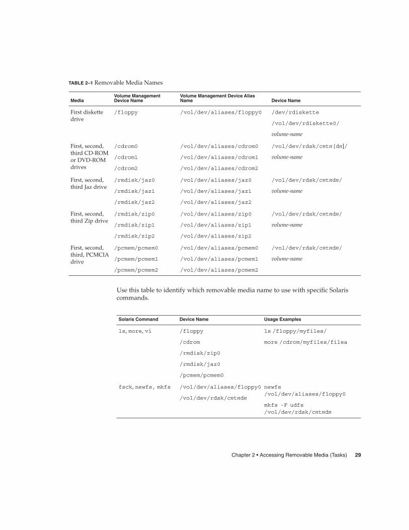
TABLE 2–1 Removable Media Names
MediaVolume ManagementDevice Name
Volume Management Device AliasName Device Name
First diskettedrive
/floppy /vol/dev/aliases/floppy0 /dev/rdiskette
/vol/dev/rdiskette0/
volume-name
First, second,third CD-ROMor DVD-ROMdrives
/cdrom0
/cdrom1
/cdrom2
/vol/dev/aliases/cdrom0
/vol/dev/aliases/cdrom1
/vol/dev/aliases/cdrom2
/vol/dev/rdsk/cntn[dn]/
volume-name
First, second,third Jaz drive
/rmdisk/jaz0
/rmdisk/jaz1
/rmdisk/jaz2
/vol/dev/aliases/jaz0
/vol/dev/aliases/jaz1
/vol/dev/aliases/jaz2
/vol/dev/rdsk/cntndn/
volume-name
First, second,third Zip drive
/rmdisk/zip0
/rmdisk/zip1
/rmdisk/zip2
/vol/dev/aliases/zip0
/vol/dev/aliases/zip1
/vol/dev/aliases/zip2
/vol/dev/rdsk/cntndn/
volume-name
First, second,third, PCMCIAdrive
/pcmem/pcmem0
/pcmem/pcmem1
/pcmem/pcmem2
/vol/dev/aliases/pcmem0
/vol/dev/aliases/pcmem1
/vol/dev/aliases/pcmem2
/vol/dev/rdsk/cntndn/
volume-name
Use this table to identify which removable media name to use with specific Solariscommands.
Solaris Command Device Name Usage Examples
ls, more, vi /floppy
/cdrom
/rmdisk/zip0
/rmdisk/jaz0
/pcmem/pcmem0
ls /floppy/myfiles/
more /cdrom/myfiles/filea
fsck, newfs, mkfs /vol/dev/aliases/floppy0
/vol/dev/rdsk/cntndn
newfs/vol/dev/aliases/floppy0
mkfs -F udfs/vol/dev/rdsk/cntndn
Chapter 2 • Accessing Removable Media (Tasks) 29
Guidelines for Accessing Removable Media DataMost CDs and DVDs are formatted to the ISO 9660 standard, which is portable, somost CDs and DVDs can be mounted by volume management. However, CDs orDVDs with UFS file systems are not portable between architectures, so they must beused on the architecture for which they were designed.
For example, a CD or DVD with a UFS file system for a SPARC platform cannot berecognized by an x86 platform. Likewise, an x86 UFS CD cannot be mounted byvolume management on a SPARC platform. The same limitation applies to diskettes.(Actually, some architectures share the same bit structure, so occasionally a UFSformat specific to one architecture will be recognized by another architecture, but theUFS file system structure was not designed to guarantee this compatibility).
To accommodate the different formats, the CD or DVD is split into slices, which aresimilar in effect to partitions on hard disks. The 9660 portion is portable, but the UFSportion is architecture-specific. If you are having trouble mounting a CD or DVD,particularly if it is an installation CD or DVD, make sure its UFS file system isappropriate for your system’s architecture (check the label on the CD or DVD).
Accessing Jaz Drives or Zip DrivesYou can determine whether accessing your Jaz or Zip drives changes from previousSolaris releases, depending on the following:
� If you are upgrading from the Solaris 8 6/00 release to the Solaris 9 release, you cancontinue to access your Jaz drives and Zip drives in the same way as in previousreleases.
� If you are freshly installing the Solaris 9 release, you cannot access your Jaz drivesand Zip drives in the same way as in previous Solaris releases.
Follow these steps if you want to access your Jaz and Zip drives in the same wayas in previous Solaris releases:
1. Comment the following line in the /etc/vold.conf file by inserting a pound(#) sign at the beginning of the text, like this:
# use rmdisk drive /dev/rdsk/c*s2 dev_rmdisk.so rmdisk%d
2. Reboot the system.
� How to Add a New Removable Media DriveAdding a new removable media drive involves creating the /reconfigure file andrebooting the system so that volume management recognizes the new media drive.
1. Become superuser.Steps
30 System Administration Guide: Devices and File Systems • September 2004

2. Create the /reconfigure file.
# touch /reconfigure
3. Bring the system to run level 0.
# init 0
4. Turn off power to the system.
5. Connect the new media drive.
See your hardware handbook for specific instructions.
6. Turn on power to the system.
The system comes up to multiuser mode automatically.
Stopping and Starting Volume Management (vold)Occasionally, you might want to manage media without the help of volumemanagement. This section describes how to stop and restart volume management.
� How to Stop Volume Management (vold)
1. Make sure media is not being used.
If you are not sure whether you have found all users of the media, use the fusercommand, as described in “How to Find Out If Removable Media Is Still in Use”on page 34.
2. Become superuser.
3. Enter the volmgt stop command.
# /etc/init.d/volmgt stop
#
� How to Restart Volume Management (vold)
1. Become superuser.
2. Enter the volmgt start command.
# /etc/init.d/volmgt start
volume management starting.
Steps
Steps
Chapter 2 • Accessing Removable Media (Tasks) 31

� How to Access Information on Removable Media
1. Insert the media.
The media is mounted after a few seconds.
2. Check for media in the drive.
% volcheck
Use the appropriate device name to access information by using the command-lineinterface. See Table 2–1 for an explanation of device names.
3. List the contents of the media.
% ls /media
Accessing Information on Removable Media
Access information on a diskette as follows:
$ volcheck$ ls /floppy
myfile
Access information on a Jaz drive as follows:
$ volcheck$ ls /rmdisk
jaz0/ jaz1/
Access information on a CD-ROM as follows:
$ volcheck$ ls /cdrom
cdrom0@ solaris_9_sparc
View the symbolic links on a CD-ROM as follows:
$ ls -lL /cdrom/cdrom0total 24dr-xr-xr-x 2 root sys 2048 Dec 3 11:54 s0/drwxr-xr-x 18 root root 512 Dec 3 13:09 s1/drwxr-xr-x 2 root root 512 Dec 3 13:10 s2/drwxr-xr-x 2 root root 512 Dec 3 13:10 s3/drwxr-xr-x 2 root root 512 Dec 3 13:10 s4/
drwxr-xr-x 2 root root 512 Dec 3 13:10 s5/
Access information on a PCMCIA memory card as follows
$ ls /pcmem/pcmem0
pcmem0 myfiles
Steps
Example 2–1
32 System Administration Guide: Devices and File Systems • September 2004

� How to Copy Information From Removable MediaYou can access files and directories on removable media just like any other file system.The only significant restrictions are ownership and permissions.
For instance, if you copy a file from a CD into your file system, you’ll be the owner,but you won’t have write permissions (because the file never had them on the CD).You’ll have to change the permissions yourself.
1. Make sure the media is mounted.
$ ls /media
The ls command displays the contents of a mounted media. If no contents aredisplayed, see “How to Access Information on Removable Media” on page 32.
2. (Optional) Copy the files or directories.
For example, for a CD, you would do the following:
$ cp /cdrom/sol_9_1202_sparc/s0/Solaris_9/Tools/add_install_client .$ ls -l
-rwxr-xr-x 1 pmorph gelfs 59586 Jan 16 2004 add_install_client*
For example, for a PCMCIA memory card, you would do the following:
$ cp /pcmem/pcmem0/readme2.doc .
$ cp -r /pcmem/pcmem0/morefiles .
� How to Play a Musical CD or DVDTo play musical media from a media drive attached to a system running the Solarisrelease, you’ll need to access public domain software, such as xmcd, that is availablefrom the following locations:
� http://www.ibiblio.org/tkan/xmcd
This site includes frequent updates to the xmcd software, which includes theversion of xmcd that plays on newer Sun hardware, such as the Sun Blade™systems.
� http://www.sun.com/software/solaris/freeware/pkgs_download.html
Keep the following in mind when using the xmcd software with CDDA (CD DigitalAudio) support to play musical media:
� Use xmcd, version 3.1 (or later) on Sun Blade systems because this version hasCDDA support, which must be enabled in order to listen to CDs on these systems.
� Enable CDDA by launching xmcd, clicking on the options button (it has a hammerand screwdriver on the button), and then by clicking on “CDDA playback”.
� When CDDA is enabled, audio is directed to the audio device, so headphones andexternal speakers should be connected to the audio device and not to the mediadrive itself.
Steps
Chapter 2 • Accessing Removable Media (Tasks) 33
� CDDA can be enabled on other machines too. Enabling CDDA is required forplaying media on the Sun Blade systems.
Consider the following issues as well:
� If you are using xmcd with standard playback on a system that does not have aninternal connection from the CD-ROM to the audio device, you must insertheadphones into the CD-ROM drive’s headphone port.
� If you are using xmcd with standard playback on a system that does have aninternal connection from the CD-ROM to the audio device, you can do either of thefollowing:
1. Insert headphones into the headphone port of the CD-ROM drive.2. Insert headphones into the headphone port on the audio device.
If you choose #2, you must do the following:
� Select the internal CD as the input device.� Make sure that Monitor Volume is non-zero.
You can do both of these from sdtaudiocontrol’s record panel.
Once you install the xmcd software, you can play a musical CD simply by inserting itinto the CD-ROM drive and starting the xmcd control panel.
1. Install the xmcd software.
2. Insert the media into the media drive.
3. Invoke the xmcd command.
% ./xmcd &
� How to Find Out If Removable Media Is Still inUse
1. Become superuser.
2. Identify the processes accessing the media.
# fuser -u [-k] /media
-u Displays the user of the media.
-k Kills the process accessing the media.
For more information on using the fuser command, see fuser(1M).
3. (Optional) Kill the process accessing the media.
Steps
Steps
34 System Administration Guide: Devices and File Systems • September 2004

# fuser -u -k /media
Caution – Killing the process accessing the media should only be used in emergencysituations.
4. Verify the process is gone.
# pgrep process-ID
Finding Out If the Media Is Still in Use
The following example shows that the process 26230c, owner pmorph, is accessingthe /cdrom/sol_9_1202_sparc/s0/Solaris_9/Tools/ directory.
# fuser -u /cdrom/sol_9_1202_sparc/s0/Solaris_9/Tools/
/cdrom/sol_9_1202_sparc/s0/Solaris_9/Tools/: 7258c(pmorph)
� How to Eject Removable Media
1. Make sure the media is not being used.
Remember, media is “being used” if a shell or an application is accessing any of itsfiles or directories. If you are not sure whether you have found all users of a CD (ashell hidden behind a desktop tool might be accessing it), use the fusercommand, as described in “How to Find Out If Removable Media Is Still in Use”on page 34.
2. Eject the media.
# eject media
For example, for a CD, you would do the following
# eject cdrom
For example, for a PCMCIA memory card, you would do the following:
# eject pcmem0
Example 2–2
Steps
Chapter 2 • Accessing Removable Media (Tasks) 35

Accessing Removable Media on aRemote System (Task Map)The following table describes the tasks need to access removable media on a remotesystem.
Task Description For Instructions
1. Make local media availableto remote systems
Add the removable mediadrive to your system, ifnecessary.
“How to Make Local MediaAvailable to Other Systems”on page 36
2. Access removable media onremote systems
Insert the media into thedrive.
“How to Access Informationon Removable Media”on page 32
� How to Make Local Media Available to OtherSystemsYou can configure your system to share its media drives to make any media in thosedrives available to other systems. (This does not apply to musical CDs.) Once yourmedia drives are shared, other systems can access the media they contain simply bymounting them, as described in “How to Access Removable Media on RemoteSystems” on page 39.
1. Become superuser.
2. Find out whether the NFS daemon (nfsd) is running.
# ps -ef | grep nfsdroot 14533 1 17 10:46:55 ? 0:00 /usr/lib/nfs/nfsd -a 16
root 14656 289 7 14:06:02 pts/3 0:00 grep nfsd
If the daemon is running, a line for /usr/lib/nfs/nfsd will appear, as shownabove. If the daemon is not running, only the grep nfsd line will appear.
3. Identify the nfsd status and select one of the following:
a. If nfsd is running, go to Step 8.
b. If nfsd is not running, continue with Step 4.
4. Create a dummy directory for nfsd to share.
# mkdir / dummy-dir
Steps
36 System Administration Guide: Devices and File Systems • September 2004

The dummy-dir mount point can be any directory name. For example, dummy. Thisdirectory will not contain any files. Its only purpose is to “wake up” the NFSdaemon so that it notices your shared media drive.
5. Add the following entry into the /etc/dfs/dfstab file.
share -F nfs -o ro [-d comment] /dummy-dir
When you start the NFS daemon, it will see this entry, “wake up,” and notice theshared media drive. Note that the comment (preceded by -d) is optional.
6. Start the NFS daemon.
# /etc/init.d/nfs.server start
7. Verify that the NFS daemon is indeed running.
# ps -ef | grep nfsdroot 14533 1 17 10:46:55 ? 0:00 /usr/lib/nfs/nfsd -a 16
root 14656 289 7 14:06:02 pts/3 0:00 /grep nfsd
8. Eject any media currently in the drive.
# eject media
9. Assign root write permissions to the /etc/rmmount.conf file.
# chmod 644 /etc/rmmount.conf
10. Add the following lines to the /etc/rmmount.conf file.
# File System Sharing
share media*
These lines share any media loaded into your system’s CD-ROM drive. You can,however, limit sharing to a particular CD or series of CDs, as described inshare(1M).
11. Remove write permissions from the /etc/rmmount.conf file.
# chmod 444 /etc/rmmount.conf
This step returns the file to its default permissions.
12. Load the media.
The media you now load, and all subsequent media, will be available to othersystems. Remember to wait until the light on the drive stops blinking before youverify this task.To access the media, the remote user must mount it by name, according to theinstructions in “How to Access Removable Media on Remote Systems” on page 39.
13. Verify that the media is indeed available to other systems by using the sharecommand.
If the media is available, its share configuration will be displayed. (The shareddummy directory will also be displayed.)
Chapter 2 • Accessing Removable Media (Tasks) 37

# share- /dummy ro "dummy dir to wake up NFS daemon"- /cdrom/sol_9_1202_sparc/s5 ro ""- /cdrom/sol_9_1202_sparc/s4 ro ""- /cdrom/sol_9_1202_sparc/s3 ro ""- /cdrom/sol_9_1202_sparc/s2 ro ""- /cdrom/sol_9_1202_sparc/s1 ro ""
- /cdrom/sol_9_1202_sparc/s0 ro ""
Making Local CDs Available to Other Systems
The following example shows how to make any local CD available to other systems onthe network.
# ps -ef | grep nfsdroot 10127 9986 0 08:25:01 pts/2 0:00 grep nfsdroot 10118 1 0 08:24:39 ? 0:00 /usr/lib/nfs/nfsd -a
# mkdir /dummy# vi /etc/dfs/dfstab(Add the following line:)share -F nfs -o ro /dummy# eject cdrom0# chmod 644 /etc/rmmount.conf# vi /etc/rmmount.conf(Add the following line to the File System Sharing section:)share cdrom*# chmod 444 /etc/rmmount.conf(Load a CD.)# share- /dummy ro ""- /cdrom/sol_9_1202_sparc/s5 ro ""- /cdrom/sol_9_1202_sparc/s4 ro ""- /cdrom/sol_9_1202_sparc/s3 ro ""- /cdrom/sol_9_1202_sparc/s2 ro ""- /cdrom/sol_9_1202_sparc/s1 ro ""
- /cdrom/sol_9_1202_sparc/s0 ro ""
Making Local Diskettes Available to Other Systems
The following example shows how to make any local diskette available to othersystems on the network.
# ps -ef | grep nfsdroot 10127 9986 0 08:25:01 pts/2 0:00 grep nfsdroot 10118 1 0 08:24:39 ? 0:00 /usr/lib/nfs/nfsd -a
# mkdir /dummy# vi /etc/dfs/dfstab(Add the following line:)share -F nfs -o ro /dummy# eject floppy0# chmod 644 /etc/rmmount.conf# vi /etc/rmmount.conf(Add the following line to the File System Sharing section.)
Example 2–3
Example 2–4
38 System Administration Guide: Devices and File Systems • September 2004

share floppy*# chmod 444 /etc/rmmount.conf(Load a diskette.)# volcheck -vmedia was found# share- /dummy ro ""
- /floppy/myfiles rw ""
Making Local PCMCIA Memory Cards Available to Other Systems
The following example shows how to make any local PCMCIA memory card availableto other systems on the network.
# ps -ef | grep nfsdroot 10127 9986 0 08:25:01 pts/2 0:00 grep nfsdroot 10118 1 0 08:24:39 ? 0:00 /usr/lib/nfs/nfsd -a
# mkdir /dummy# vi /etc/dfs/dfstab(Add the following line:)share -F nfs -o ro /dummy# eject pcmem0# chmod 644 /etc/rmmount.conf# vi /etc/rmmount.conf(Add the following line to the File System Sharing section:)share floppy*# chmod 444 /etc/rmmount.conf(Load a PCMCIA memory card.)# volcheck -vmedia was found# share- /dummy ro ""
- /pcmem/myfiles rw ""
� How to Access Removable Media on RemoteSystemsYou can access media on a remote system by mounting it manually into your filesystem, provided the other system has shared its media according to the instructionsin “How to Make Local Media Available to Other Systems” on page 36.
1. Select an existing directory to serve as the mount point or create one.
$ mkdir directory
directory is the name of the directory that you create to serve as a mount point forthe other system’s CD.
2. Find the name of the media you want to mount.
$ showmount -e system-name
Example 2–5
Steps
Chapter 2 • Accessing Removable Media (Tasks) 39

For example:
export list for starbug:/dummy (everyone)/cdrom/sol_9_1202_sparc/s5 (everyone)/cdrom/sol_9_1202_sparc/s4 (everyone)/cdrom/sol_9_1202_sparc/s3 (everyone)/cdrom/sol_9_1202_sparc/s2 (everyone)/cdrom/sol_9_1202_sparc/s1 (everyone)
/cdrom/sol_9_1202_sparc/s0 (everyone)
As superuser, mount the media.
# mount -F nfs -o ro system-name:/media/media-name local-mount-point
system-name The name of the system whose media you will mount.
media-name The name of the media you want to mount.
local-mount-point The local directory onto which you will mount the remotemedia.
3. Log out as superuser.
4. Verify that the media is mounted.
$ ls /media
Accessing CDs on Other Systems
The following example shows how to mount the CD named sol_9_1202_sparcfrom the remote system starbug onto the /mnt directory of the local system.
$ showmount -e starbugexport list for starbug:/dummy (everyone)/cdrom/sol_9_1202_sparc/s5 (everyone)/cdrom/sol_9_1202_sparc/s4 (everyone)/cdrom/sol_9_1202_sparc/s3 (everyone)/cdrom/sol_9_1202_sparc/s2 (everyone)/cdrom/sol_9_1202_sparc/s1 (everyone)/cdrom/sol_9_1202_sparc/s0 (everyone)$ suPassword: password# mount -F nfs -o ro starbug:/cdrom/sol_9_1202_sparc/s0 /mnt# exit$ ls /mnt
Copyright Solaris_9
Accessing Diskettes on Other Systems
The following example shows how to mount the diskette named myfiles from theremote system mars onto the /floppy directory of the local system.
Example 2–6
Example 2–7
40 System Administration Guide: Devices and File Systems • September 2004

$ cd /net/mars$ ls /floppyfloppy0 myfiles$ suPassword: password# mount -F nfs mars:/floppy/myfiles /floppy# exit$ ls /floppy
myfiles
Accessing PCMCIA Memory Cards on Other Systems
The following example shows how to mount the PCMCIA memory card namedmyfiles from the remote system mars onto the /pcmem directory of the local system.
$ cd /net/mars$ ls /pcmempcmem0 myfiles$ suPassword: password# mount -F nfs mars:/pcmem/myfiles /pcmem# exit$ ls /pcmem
myfiles
Example 2–8
Chapter 2 • Accessing Removable Media (Tasks) 41

42 System Administration Guide: Devices and File Systems • September 2004

CHAPTER 3
Formatting Removable Media (Tasks)
This chapter describes how to format removable media from the command line in theSolaris environment.
For information on the procedures associated with formatting removable media, see“Formatting Removable Media (Task Map)” on page 43.
For background information on removable media, see Chapter 1.
Formatting Removable Media (TaskMap)
Task Description For Instructions
1. Load unformattedmedia
Insert the media into the drive andenter the volcheck command.
“How to Load aRemovable Media”on page 46
2. Format the media Format removable media. “How to FormatRemovable Media(rmformat)” on page 48
3. (Optional) Add a UFSfile system
Add a UFS file system to use thediskette for transferring files.
“How to FormatRemovable Media forAdding a File System”on page 49
43

Task Description For Instructions
4. (Optional) Check themedia
Verify the integrity of the file systemon the media.
“How to Check a FileSystem on RemovableMedia” on page 50
5. (Optional) Repair badblocks on the media
Repair any bad blocks on the media, ifnecessary.
“How to Repair Bad Blockson Removable Media”on page 51
6. (Optional) ApplyRead or Write andPassword Protection
Apply read or write protection orpassword protection on the media, ifnecessary.
“How to Enable or DisableWrite Protection onRemovable Media”on page 52
Formatting Removable Media OverviewThe rmformat command is a non-superuser utility that you can use to format andprotect rewritable removable media. The rmformat command has three formattingoptions:
� quick – This option formats removable media without certification or with limitedcertification of certain tracks on the media.
� long – This option formats removable media completely. For some devices, the useof this option might include the certification of the whole media by the drive itself.
� force – This option formats completely without user confirmation. For mediawith a password-protection mechanism, this option clears the password beforeformatting. This feature is useful when a password is forgotten. On media withoutpassword protection, this option forces a long format.
Formatting Removable Media GuidelinesKeep the following in mind when formatting removable media:
� Close and quit the file manager window.
File Manager automatically displays a formatting window when you insert anunformatted media. To avoid the window, quit from File Manager. If you prefer tokeep File Manager open, quit the formatting window when it appears.
� Volume manager (vold) mounts file systems automatically so you might have tounmount media before you can format it, if it contains an existing file system.
44 System Administration Guide: Devices and File Systems • September 2004

Removable Media Hardware ConsiderationsThis section describes removable media hardware considerations.
Diskette Hardware ConsiderationsKeep the following in mind when formatting diskettes:
� For information on diskette names, see Table 2–1.
� Diskettes that are not named (that is, they have no “label”) are assigned the defaultname of noname.
A Solaris system can format diskettes for use on both Solaris and DOS systems.However, the hardware platform imposes some limitations. These limitations aresummarized in the following table.
Platform Type Diskettes Format Type
SPARC based systems UFS
MS-DOS or NEC-DOS (PCFS)
UDFS
x86 based systems UFS
MS-DOS or NEC-DOS (PCFS)
UDFS
Diskettes formatted for UFS are restricted to the hardware platform on which theywere formatted. In other words, a UFS diskette formatted on a SPARC based platformcannot be used for UFS on an x86 platform, nor can a diskette formatted on an x86platform be used on a SPARC based platform. This is because the SPARC and x86 UFSformats are different. SPARC uses little-endian bit coding, x86 uses big-endian.
A complete format for SunOS file systems consists of the basic “bit” formatting plusthe structure to support a SunOS file system. A complete format for a DOS file systemconsists of the basic “bit” formatting plus the structure to support either an MS-DOSor an NEC-DOS file system. The procedures required to prepare a diskette for eachtype of file system are different. Therefore, before you format a diskette, considerwhich procedure to follow. For more information, see “Formatting Removable Media(Task Map)” on page 43.
On a Solaris system (either SPARC or x86), you can format diskettes with thefollowing densities.
Chapter 3 • Formatting Removable Media (Tasks) 45

Diskette Size Diskette Density Capacity
3.5” High Density (HD) 1.44 Mbytes
3.5” Double Density (DD) 720 Kbytes
By default, the diskette drive formats a diskette to a like density. This default meansthat a 1.44 Mbyte drive attempts to format a diskette for 1.44 Mbytes, whether thediskette is in fact a 1.44 Mbyte diskette or not, unless you instruct it otherwise. Inother words, a diskette can be formatted to its capacity or lower, and a drive canformat to its capacity or lower.
PCMCIA Memory Card Hardware ConsiderationsA Solaris platform can format PCMCIA memory cards for use on both Solaris andDOS platforms. However, the hardware platform imposes some limitations. Theselimitations are summarized in the following table.
Platform Type PCMCIA Memory Cards Format Type
SPARC based systems UFS
MS-DOS or NEC-DOS (PCFS)
x86 based systems UFS
MS-DOS or NEC-DOS (PCFS)
PCMCIA memory cards formatted for UFS are restricted to the hardware platform onwhich they were formatted. In other words, a UFS PCMCIA memory card formattedon a SPARC platform cannot be used for UFS on an x86 platform. Likewise, PCMCIAmemory cards formatted on an x86 platform cannot be used on a SPARC platform.This is because the SPARC and x86 UFS formats are different.
A complete format for UFS file systems consists of the basic “bit” formatting plus thestructure to support a UFS file system. A complete format for a DOS file systemconsists of the basic “bit” formatting plus the structure to support either an MS-DOSor an NEC-DOS file system. The procedures required to prepare a PCMCIA memorycard for each type of file system are different. Therefore, before you format a PCMCIAmemory card, consider which file system you are using.
� How to Load a Removable Media
1. Insert the media.
2. Make sure the media is formatted.
Steps
46 System Administration Guide: Devices and File Systems • September 2004

If you aren’t sure, insert it and check the status messages in the console, asdescribed in Step 3. If you need to format the diskette, go to “How to FormatRemovable Media (rmformat)” on page 48.
3. Notify volume management.
$ volcheck -v media was found
Two status messages are possible:
media was found Volume management detected the media and willattempt to mount it in the directory described in Table2–1.
If the media is formatted properly, no error messagesappear in the console.
If the media is not formatted, the “media was found”message is still displayed, but the error messagessimilar to the following appear in the Console:
fd0: unformatted diskette or no diskettein the drive
fd0: read failed (40 1 0)
fd0: bad format
You must format the media before volumemanagement can mount it. For more information, seeChapter 3.
no media was found Volume management did not detect the media. Makesure the media is inserted properly and run volcheckagain. If unsuccessful, check the media, it could bedamaged. You can also try to mount the mediamanually.
4. Verify that the media was mounted by listing its contents.
For example, do the following for a diskette:
$ ls /floppy
floppy0 myfiles
As described earlier, floppy0 is a symbolic link to the actual name of the diskette,In this case, myfiles. If the diskette has no name but is formatted correctly, thesystem will refer to it as unnamed_floppy.
If nothing appears under the /floppy directory, the diskette was either notmounted or is not formatted properly. To find out, run the mount command andlook for the line that begins with /floppy (usually at the end of the listing):
/floppy/name on /vol/dev/diskette0/name
Chapter 3 • Formatting Removable Media (Tasks) 47
If the line does not appear, the diskette was not mounted. Check the consolewindow for error messages.
� How to Format Removable Media (rmformat)You can use the rmformat command to format the media. By default, this commandcreates two partitions on the media: partition 0 and partition 2 (the whole media).
1. Verify that the volume manager is running, which means you can use the shorternickname for the device name.
$ ps -ef | grep vold
root 212 1 0 Nov 03 ? 0:01 /usr/sbin/vold
For information on starting vold, see “How to Restart Volume Management(vold)” on page 31. For information on identifying media device names, see“Using Removable Media Names” on page 28.
2. Format the removable media.
$ rmformat -F [ quick | long | force ] device-name
See the previous section for more information on rmformat formatting options.
If the rmformat output indicates bad blocks, see “How to Repair Bad Blocks onRemovable Media” on page 51 for information on repairing bad blocks.
3. (Optional) Label the removable media with an 8-character label to be used in theSolaris environment.
$ rmformat -b label device-name
For information on creating a DOS label, see mkfs_pcfs(1M).
Formatting Removable Media
This example shows how to format a diskette.
$ rmformat -F quick /dev/rdisketteFormatting will erase all the data on disk.Do you want to continue? (y/n) y
.........................................................................
This example shows how to format a Zip drive.
$ rmformat -F quick /vol/dev/aliases/zip0Formatting will erase all the data on disk.Do you want to continue? (y/n) y
.........................................................................
Steps
Example 3–1
48 System Administration Guide: Devices and File Systems • September 2004

� How to Format Removable Media for Adding aFile System
1. Format the media.
$ rmformat -F quick device-name
2. (Optional) Create an alternate Solaris partition table.
$ rmformat -s slice-file device-name
A sample slice file looks like the following:
slices: 0 = 0, 30MB, "wm", "home" :1 = 30MB, 51MB :2 = 0, 94MB, "wm", "backup" :
6 = 81MB, 13MB
3. Become superuser.
4. Determine the appropriate file system type and select one of the following:
a. Create a UFS file system.
# newfs device-name
b. Create a UDFS file system.
# mkfs -F udfs device-name
Formatting a Diskette for a UFS File System
The following example shows how to format a diskette and create a UFS file systemon the diskette.
$ rmformat -F quick /vol/dev/aliases/floppy0Formatting will erase all the data on disk.Do you want to continue? (y/n) y$ su# /usr/sbin/newfs /vol/dev/aliases/floppy0newfs: construct a new file system /dev/rdiskette: (y/n)? y/dev/rdiskette: 2880 sectors in 80 cylinders of 2 tracks, 18 sectors
1.4MB in 5 cyl groups (16 c/g, 0.28MB/g, 128 i/g)super-block backups (for fsck -F ufs -o b=#) at:32, 640, 1184, 1792, 2336,
#
Formatting a PCMCIA Memory Card for a UFS File System
The following example shows how to format a PCMCIA memory card and create aUFS file system on the card.
Steps
Example 3–2
Example 3–3
Chapter 3 • Formatting Removable Media (Tasks) 49
$ rmformat -F quick /vol/dev/aliases/pcmem0$ su# /usr/sbin/newfs -v /vol/dev/aliases/pcmem0newfs: construct a new file system /vol/dev/aliases/pcmem0:(y/n)? y...
#
Formatting Removable Media for a PCFS File System
This example shows how to create an alternate fdisk partition.
$ rmformat -F quick /dev/rdsk/c0t4d0s2:cFormatting will erase all the data on disk.Do you want to continue? (y/n) y$ su# fdisk /dev/rdsk/c0t4d0s2:c# mkfs -F pcfs /dev/rdsk/c0t4d0s2:cConstruct a new FAT file system on /dev/rdsk/c0t4d0s2:c: (y/n)? y
#
This example shows how to create a PCFS file system without an fdisk partition.
$ rmformat -F quick /dev/rdisketteFormatting will erase all the data on disk.Do you want to continue? (y/n) y$ su# mkfs -F pcfs -o nofdisk,size=2 /dev/rdisketteConstruct a new FAT file system on /dev/rdiskette: (y/n)? y
#
� How to Check a File System on Removable Media
1. Become superuser.
2. Identify the name service and select one of the following:
a. Check a UFS file system.
# fsck -F ufs device-name
b. Check a UDFS file system.
# fsck -F udfs device-name
c. Check a PCFS file system.
# fsck -F pcfs device-name
Example 3–4
Steps
50 System Administration Guide: Devices and File Systems • September 2004

Checking a PCFS File System on Removable Media
The following example shows how check the consistency of a PCFS file system onmedia.
# fsck -F pcfs /dev/rdsk/c0t4d0s2** /dev/rdsk/c0t4d0s2** Scanning file system meta-data** Correcting any meta-data discrepancies1457664 bytes.0 bytes in bad sectors.0 bytes in 0 directories.0 bytes in 0 files.1457664 bytes free.512 bytes per allocation unit.2847 total allocation units.2847 available allocation units.
#
� How to Repair Bad Blocks on Removable MediaYou can only use the rmformat command to verify, analyze, and repair bad sectorsthat are found during verification if the drive supports bad block management. Mostdiskettes and PCMCIA memory cards do not support bad block management.
If the drive supports bad block management, a best effort is made to rectify the badblock. If the bad block cannot be rectified despite the best effort mechanism, a messageindicates a failure to repair.
1. Repair bad blocks on removable media.
$ rmformat -c block-numbers device-name
Supply the block number in decimal, octal, or hexadecimal format from a previousrmformat session.
2. Verify the media.
$ rmformat -V read device-name
Applying Read or Write and Password Protectionto Removable MediaYou can apply read protection or write protection and set a password on Iomegamedia such as Zip drives and Jaz drives.
Example 3–5
Steps
Chapter 3 • Formatting Removable Media (Tasks) 51
� How to Enable or Disable Write Protection onRemovable Media
1. Determine whether you want to enable or disable write protection and selectone of the following:
a. Enable write protection.
$ rmformat -w enable device-name
b. Disable write protection.
$ rmformat -w disable device-name
2. Verify whether the media’s write protection is enabled or disabled.
$ rmformat -p device-name
� How to Enable or Disable Read or Write Protectionand a Password on Iomega MediaYou can apply a password with a maximum of 32 characters for Iomega media thatsupport this feature. You cannot set read protection or write protection without apassword on Iomega media. In this situation, you are prompted to provide apassword.
You receive a warning message if you attempt to apply a password on media that doesnot support this feature.
1. Determine whether you want to enable or disable read protection or writeprotection and a password.
a. Enable read protection or write protection.
$ rmformat -W enable device-namePlease enter password (32 chars maximum): xxxPlease reenter password:
$ rmformat -R enable device-namePlease enter password (32 chars maximum): xxxPlease reenter password:
b. Disable read protection or write protection and remove the password.
$ rmformat -W disable device-namePlease enter password (32 chars maximum): xxx
Steps
Steps
52 System Administration Guide: Devices and File Systems • September 2004
$ rmformat -R disable device-namePlease enter password (32 chars maximum): xxx
2. Verify whether the media’s read protection or write protection is enabled ordisabled.
$ rmformat -p device-name
Enabling or Disabling Read or Write Protection
This example shows how to enable write protection and set a password on a Zipdrive.
$ rmformat -W enable /vol/dev/aliases/zip0Please enter password (32 chars maximum): xxxPlease reenter password: xxx
This example shows how to disable write protection and remove the password on aZip drive.
$ rmformat -W disable /vol/dev/aliases/zip0
Please enter password (32 chars maximum): xxx
This example shows how to enable read protection and set a password on a Zip drive.
rmformat -R enable /vol/dev/aliases/zip0Please enter password (32 chars maximum): xxxPlease reenter password: xxx
This example shows to disable read protection and remove the password on a Zipdrive.
$ rmformat -R disable /vol/dev/aliases/zip0
Please enter password (32 chars maximum): xxx
Example 3–6
Chapter 3 • Formatting Removable Media (Tasks) 53

54 System Administration Guide: Devices and File Systems • September 2004
CHAPTER 4
Writing CDs (Tasks)
This chapter provides step-by-step instructions for writing and copying data andaudio CDs with the cdrw command.
� “How to Restrict User Access to Removable Media with RBAC” on page 58� “How to Identify a CD Writer” on page 58� “How to Check the CD Media” on page 59� “How to Create an ISO 9660 File System for a Data CD” on page 60� “How to Create a Multi-Session Data CD” on page 61� “How to Create an Audio CD” on page 63� “How to Extract an Audio Track on a CD” on page 64� “How to Copy a CD” on page 65� “How to Erase CD-RW Media” on page 65
Working with Audio and Data CDsYou can use the cdrw command to write CD file systems in ISO 9660 format withRock Ridge or Joliet extensions on CD-R or CD-RW media devices.
You can use the cdrw command to:
� Create data CDs� Create audio CDs� Extract audio data from an audio CD� Copy CDs� Erase CD-RW media
The cdrw command is available in the following releases:
� Software Supplement for the Solaris 8 Operating Environment 1/01 CD� Part of the Solaris environment starting in the Solaris 9 release
55
For information on recommended CD-R or CD-RW devices, go tohttp://www.sun.com/io_technologies/pci/removable.html.
CD Media Commonly Used TermsCommonly used terms when referring to CD media are:
Term Description
CD-R CD read media that can be written once and after that, canonly be read from.
CD-RW CD rewritable media that can be written to and erased.CD-RW media can only be read by CD-RW devices.
ISO 9660 ISO, an acronym for Industry Standards Organization, is anorganization that sets standards computer storage formats.
An ISO 9660 file system is a standard CD-ROM file systemthat enables you to read the same CD-ROM on any majorcomputer platform. The standard, issued in 1988, waswritten by an industry group named High Sierra, namedafter the High Sierra Hotel in Nevada. Almost allcomputers with CD-ROM drives can read files from an ISO9660 file system.
Joliet extensions
Rock Ridge extensions
Adds Windows™ file system information.
Adds UNIX™ file system information. (Rock Ridge isnamed after the town in Blazing Saddles.)
Note – These extensions are not exclusive. You can specifyboth mkisofs -R and -j options for compatibility withboth systems. (See mkisofs(1M) for details.)
MMC-compliant record Acronym for Multi Media Command, which means theserecorder comply with a common command set. Programsthat can write to one MMC-compliant recorder should beable to write to all others.
Red Book CDDA Acronym for Compact Disc Digital Audio, which is anindustry standard method for storing digital audio oncompact discs. It is also known by the term “Red Book”format. The official industry specification calls for one ormore audio files sampled in 16-bit stereo sound at asampling rate of 44.1 kilohertz (kHz).
Commonly used terms when working with the CD media are:
56 System Administration Guide: Devices and File Systems • September 2004

Term Description
blanking The process of erasing data from the CD-RW media.
mkisofs Command for making a ISO file system to write onto a CD.
session A complete track with lead-in and lead-out information.
track A complete data or audio unit.
Writing Data and Audio CDsThe process of writing to a CD cannot be interrupted and needs a constant stream ofdata. Consider using the cdrw -S option to simulate writing to the media to verify ifthe system can provide data at a rate good enough for writing to the CD.
Write errors can be caused by one of the following:
� The media cannot handle the drive speed. For example, some media are onlycertified for 2x or 4x speeds.
� The system is running too many heavy processes that can starve the writingprocess.
� Network congestion can cause delays in reading the image if the image is on aremote system.
� The source drive might be slower than the destination drive when copying fromCD-to-CD.
If any of these problems occur, you can lower the writing speed of the device with thecdrw -p option.
For example, simulate writing at 4x speed.
$ cdrw -iS -p 4 image.iso
You can also use the cdrw -C option to use the stated media capacity for copying an80–minute CD. Otherwise, the cdrw command uses a default value of 74 minutes forcopying an audio CD.
For more information, see cdrw(1).
Chapter 4 • Writing CDs (Tasks) 57

Restricting User Access to Removable Media withRBACBy default, all users can access removable media starting in the Solaris 9 release.However, you can restrict user access to removable media by setting up a role throughrole based access control (RBAC). Access to removable media is restricted by assigningthe role to a limited set of users.
For a discussion of using roles, see Chapter 5, “Role-Based Access Control(Overview),” in System Administration Guide: Security Services.
� How to Restrict User Access to Removable Mediawith RBAC
1. Become superuser or assume an equivalent role.
2. Start the Solaris Management Console.
$ /usr/sadm/bin/smc &
For more information on starting the console, see “Starting the Solaris ManagementConsole” in System Administration Guide: Basic Administration.
3. Set up a role that includes the Device Management rights.
For more information, see Chapter 6, “Role-Based Access Control (Tasks),” inSystem Administration Guide: Security Services.
4. Add users who need to use the cdrw command to the newly created role.
5. Comment the following line in the /etc/security/policy.conf file.
AUTHS_GRANTED=solaris.device.cdrw
If you do not do this step, all users still have access to the cdrw command, not justthe members of the device management role.
After this file is modified, the device management role members are the only userswho can use the cdrw command. Everyone else is denied access with the followingmessage:
Authorization failed, Cannot access disks.
How to Identify a CD WriterUse the cdrw -l command to identify the CD writers on the system.
$ cdrw -lLooking for CD devices...
Node | Connected Device | Device type
Steps
58 System Administration Guide: Devices and File Systems • September 2004

----------------------+--------------------------------+-----------------
cdrom0 | YAMAHA CRW8424S 1.0d | CD Reader/Writer
If you want to use a specific CD writer, use the -d option. For example:
$ cdrw -a filename.wav -d cdrom2
Use the cdrw -M command to to identify whether the media is blank or whether thereis an existing table of contents.
$ cdrw -M
Device : YAMAHA CRW8424SFirmware : Rev. 1.0d (06/10/99)Media is blank
%
� How to Check the CD MediaThe cdrw command works with or without vold running. However, you must havesuperuser or role access to stop and start the vold daemon.
1. Insert a CD into the CD-RW device.
The CD can be any CD that the device can read.
2. Check that the CD-RW drive is connected properly by listing the device.
$ cdrw -lLooking for CD devices...
Node Connected Device Device type----------------------+--------------------------------+-----------------
cdrom1 | YAMAHA CRW8424S 1.0d | CD Reader/Writer
3. (Optional) If you do not see the drive in the list, you might have to do areconfiguration boot so that the system recognizes the device.
# touch /reconfigure
# init 6
Or, use the following commands to add the CD-RW device without rebooting thesystem.
# drvconfig
# disks
Then restart vold.
# /etc/init.d/vold stop
# /etc/init.d/vold start
Steps
Chapter 4 • Writing CDs (Tasks) 59
Creating a Data CDPrepare the data first by using the mkisofs command to convert the file and fileinformation into the High Sierra format used on CDs.
� How to Create an ISO 9660 File System for a DataCD
1. Insert a blank CD into the CD-RW device.
2. Create the ISO 9660 file system on the new CD.
$ mkisofs -r /pathname > cd-file-system
-r Creates Rock Ridge information and resets file ownerships tozero.
/pathname Identifies the pathname used to create the ISO 9660 file system.
> cd-file-system Identifies the name of the file system to be put on the CD.
3. Copy the CD file system onto the CD.
$ cdrw -i cd-file-system
-i cd-file-system Specifies the image file for creating a data CD.
Creating an ISO 9660 File System for a Data CD
The following example shows how to create a ISO 9660 file system for a data CD.
$ mkisofs -r /home/dubs/ufs_dir > ufs_cdTotal extents actually written = 56Total translation table size: 0Total rockridge attributes bytes: 329Total directory bytes: 0Path table size(bytes): 10Max brk space used 8000
56 extents written (0 Mb)
Then copy the CD file system onto the CD. For example:
$ cdrw -i ufs_cdInitializing device...done.Writing track 1...done.
Finalizing (Can take several minutes)...done.
Steps
Example 4–1
60 System Administration Guide: Devices and File Systems • September 2004

� How to Create a Multi-Session Data CDThis procedure describes how to put more than one session on the CD. This procedureincludes an example of copying the infoA and infoB directories onto the CD.
1. Create the file system for the first CD session.
$ mkisofs -o infoA -r -V my_infoA /data/infoATotal translation table size: 0Total rockridge attributes bytes: 24507Total directory bytes: 34816Path table size(bytes): 98Max brk space used 2e000
8929 extents written (17 Mb)
-o infoA Identifies the name of the ISO file system.
-r Creates Rock Ridge information and resets file ownerships tozero.
-V my_infoA Identifies a volume label to be used as the mount point by vold.
/data/infoA Identifies the ISO image directory to create.
2. Copy the ISO file system for the first session onto the CD.
$ cdrw -iO infoAInitializing device...done.Writing track 1...done.done.
Finalizing (Can take several minutes)...done.
-i infoA Identifies the name of the image file to write to the CD.
-O Keeps the CD open for writing.
3. Re-insert the CD after it is ejected.
4. Identify the pathname of the CD media to include in the next write session.
$ eject -n...
cdrom0 -> /vol/dev/rdsk/c2t4d0/my_infoA
Note the /vol/dev/... pathname.
5. Identify the next writeable address on the CD to write the next session.
% cdrw -M /cdromDevice : YAMAHA CRW8424SFirmware : Rev. 1.0d (06/10/99)
Track No. |Type |Start address
Steps
Chapter 4 • Writing CDs (Tasks) 61
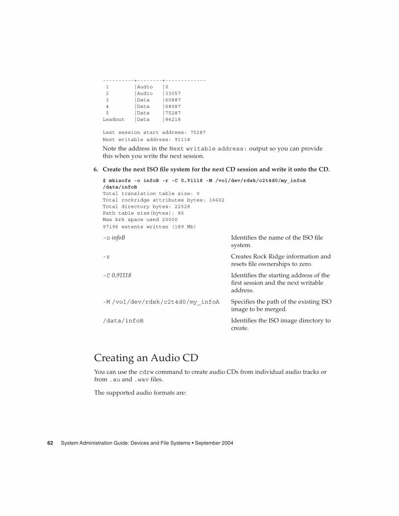
----------+--------+-------------1 |Audio |02 |Audio |330573 |Data |608874 |Data |680875 |Data |75287Leadout |Data |84218
Last session start address: 75287
Next writable address: 91118
Note the address in the Next writable address: output so you can providethis when you write the next session.
6. Create the next ISO file system for the next CD session and write it onto the CD.
$ mkisofs -o infoB -r -C 0,91118 -M /vol/dev/rdsk/c2t4d0/my_infoA/data/infoBTotal translation table size: 0Total rockridge attributes bytes: 16602Total directory bytes: 22528Path table size(bytes): 86Max brk space used 20000
97196 extents written (189 Mb)
-o infoB Identifies the name of the ISO filesystem.
-r Creates Rock Ridge information andresets file ownerships to zero.
-C 0,91118 Identifies the starting address of thefirst session and the next writableaddress.
-M /vol/dev/rdsk/c2t4d0/my_infoA Specifies the path of the existing ISOimage to be merged.
/data/infoB Identifies the ISO image directory tocreate.
Creating an Audio CDYou can use the cdrw command to create audio CDs from individual audio tracks orfrom .au and .wav files.
The supported audio formats are:
62 System Administration Guide: Devices and File Systems • September 2004

Format Description
sun Sun .au files with data in Red Book CDDA format
wav RIFF (.wav) files with data in Red Book CDDA format
cda .cda files with raw CD audio data, which is 16–bit PCMstereo at 44.1 kHz sample rate in little-endian byte order)
aur .aur files with raw CD data in big-endian byte order
If no audio format is specified, the cdrw command tries to determine the audio fileformat based on the file extension. The case of the characters in the extension isignored.
� How to Create an Audio CDThis procedure describes how to copy audio files onto a CD.
1. Insert a blank CD into the CD-RW device.
2. Change to the directory that contains the audio files.
$ cd /myaudiodir
3. Copy the audio files onto the CD.
$ cdrw -a track1.wav track2.wav track3.wav
The -a option creates an audio CD.
Creating an Audio CD
The following example shows how to create an audio CD.
$ cdrw -a bark.wav chirp.au meow.wavInitializing device...done.Writing track 1...done.done.Writing track 2...done.Writing track 3...done.done.
Finalizing (Can take several minutes)...done.
The following example shows how to create a multisession audio CD. The CD isejected after the first session is written. Re-insert the CD before the next writingsession.
$ cdrw -aO groucho.wav chico.au harpo.wavInitializing device...done.Writing track 1...done.
Steps
Example 4–2
Chapter 4 • Writing CDs (Tasks) 63
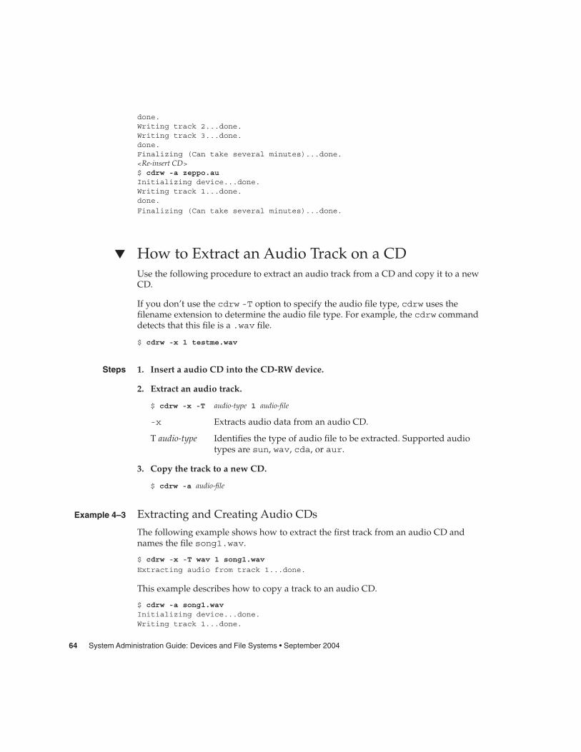
done.Writing track 2...done.Writing track 3...done.done.Finalizing (Can take several minutes)...done.<Re-insert CD>$ cdrw -a zeppo.auInitializing device...done.Writing track 1...done.done.
Finalizing (Can take several minutes)...done.
� How to Extract an Audio Track on a CDUse the following procedure to extract an audio track from a CD and copy it to a newCD.
If you don’t use the cdrw -T option to specify the audio file type, cdrw uses thefilename extension to determine the audio file type. For example, the cdrw commanddetects that this file is a .wav file.
$ cdrw -x 1 testme.wav
1. Insert a audio CD into the CD-RW device.
2. Extract an audio track.
$ cdrw -x -T audio-type 1 audio-file
-x Extracts audio data from an audio CD.
T audio-type Identifies the type of audio file to be extracted. Supported audiotypes are sun, wav, cda, or aur.
3. Copy the track to a new CD.
$ cdrw -a audio-file
Extracting and Creating Audio CDs
The following example shows how to extract the first track from an audio CD andnames the file song1.wav.
$ cdrw -x -T wav 1 song1.wav
Extracting audio from track 1...done.
This example describes how to copy a track to an audio CD.
$ cdrw -a song1.wavInitializing device...done.Writing track 1...done.
Steps
Example 4–3
64 System Administration Guide: Devices and File Systems • September 2004

Finalizing (Can take several minutes)...done.
� How to Copy a CDThis procedure describes how to extract all the tracks from an audio CD into adirectory and then copy all them onto a blank CD.
Note – By default, the cdrw command copies the CD into the /tmp directory. Thecopying might require up to 700 Mbytes of free space. If there is insufficient space inthe /tmp directory for copying the CD, use the -m option to specify an alternatedirectory.
1. Insert an audio CD into a CD-RW device.
2. Extract the tracks from the audio CD.
$ mkdir music_dir
$ cdrw -c -m music_dir
An Extracting audio ... message is display for each track.
The CD is ejected when all the tracks are extracted.
3. Insert a blank CD and press Return.
After the tracks are extracted, the audio CD is ejected, and you are prompted toinsert a blank CD.
Copying a CD
This example describes how to copy one CD to another CD. You must have twoCD-RW devices to do this task.
$ cdrw -c -s cdrom0 -d cdrom1
� How to Erase CD-RW MediaYou have to erase existing CD-RW data before the CD can be rewritten.
� Erase the entire media or just the last session on the CD by selecting one of thefollowing:
a. Erase the last session only.
$ cdrw -d cdrom0 -b session
Steps
Example 4–4
Step
Chapter 4 • Writing CDs (Tasks) 65
Erasing just the last session with the -b session option is faster than erasingthe entire media with the -b all option. You can use the -b session optioneven if you used the cdrw command to create a data or audio CD in just onesession.
b. Erase the entire media.
$ cdrw -d cdrom0 -b all
66 System Administration Guide: Devices and File Systems • September 2004

CHAPTER 5
Managing Devices (Tasks)
This chapter provides overview information and step-by-step instructions formanaging peripheral devices, such as disks, CD-ROMs, and tape devices, in theSolaris environment.
This is a list of the overview information in this chapter.
� “Where to Find Device Management Tasks” on page 68� “About Device Drivers” on page 68� “Automatic Configuration of Devices” on page 69� “Displaying Device Configuration Information” on page 71
This is a list of the step-by-step instructions in this chapter.
� “How to Display System Configuration Information” on page 72� “How to Display Device Information” on page 74� “How to Add a Device Driver” on page 76� “How to Add a Peripheral Device” on page 75
For information about accessing peripheral devices, see Chapter 9.
Device management in the Solaris environment usually involves adding and removingperipheral devices from systems, possibly adding a third-party device driver tosupport a device, and displaying system configuration information.
What’s New in Device Management?This section provides information about new device management features.
67

USB Device EnhancementsFor information on new USB device enhancements, see “What’s New in USBDevices?” on page 107.
Where to Find Device ManagementTasksThe following table describes where to find step-by-step instructions for hot-pluggingdevices and adding serial devices, such as printers and modems, and peripheraldevices, such as a disk, CD-ROM, or tape devices.
TABLE 5–1 Where to Find Instructions for Adding a Device
Device Management Task For More Information
Adding a disk that is nothot-pluggable
Chapter 12 or Chapter 13
Hot-plugging a SCSI or PCI device “SCSI Hot-Plugging With the cfgadm Command”on page 84 or “x86: PCI Hot-Plugging With the cfgadmCommand” on page 94
Hot-plugging a USB device “Hot-Plugging USB Devices (Task Map)” on page 134
Adding a CD-ROM or tape device “How to Add a Peripheral Device” on page 75
Adding a modem Chapter 10, “Managing Terminals and Modems(Overview),” in System Administration Guide: AdvancedAdministration
Adding a printer Chapter 2, “Managing Printing Services (Overview),” inSystem Administration Guide: Advanced Administration
About Device DriversA computer typically uses a wide range of peripheral and mass-storage devices. Yoursystem, for example, probably has a disk drive, a keyboard and a mouse, and somekind of magnetic backup medium. Other commonly used devices include CD-ROMdrives, printers and plotters, light pens, touch-sensitive screens, digitizers, andtablet-and-stylus pairs.
68 System Administration Guide: Devices and File Systems • September 2004

The Solaris software does not directly communicate with all these devices. Each typeof device requires different data formats, protocols, and transmission rates.
A device driver is a low-level program that allows the operating system to communicatewith a specific piece of hardware. The driver serves as the operating system’s“interpreter” for that piece of hardware.
Automatic Configuration of DevicesThe kernel, consisting of a small generic core with a platform-specific component anda set of modules, is configured automatically in the Solaris environment.
A kernel module is a hardware or software component that is used to perform aspecific task on the system. An example of a loadable kernel module is a device driverthat is loaded when the device is accessed.
The platform-independent kernel is /kernel/genunix. The platform-specificcomponent is /platform/‘uname -m‘/kernel/unix.
The kernel modules are described in the following table.
TABLE 5–2 Description of Kernel Modules
Location Directory Contents
/platform/‘uname -m‘/kernel Platform-specific kernel components
/kernel Kernel components common to all platformsthat are needed for booting the system
/usr/kernel Kernel components common to all platformswithin a particular instruction set
The system determines what devices are attached to it at boot time. Then, the kernelconfigures itself dynamically, loading needed modules into memory. At this time,device drivers are loaded when devices, such as disk and tape devices, are accessed.This process is called autoconfiguration because all kernel modules are loadedautomatically when they are needed.
You can customize the way in which kernel modules are loaded by modifying the/etc/system file. For instructions on modifying this file, see system(4).
Chapter 5 • Managing Devices (Tasks) 69

Features and Benefits of AutoconfigurationThe benefits of autoconfiguration are as follows:
� Main memory is used more efficiently because modules are loaded when needed.
� There is no need to reconfigure the kernel when new devices are added to thesystem.
� Drivers can be loaded and tested without having to rebuild the kernel and rebootthe system.
You will use autoconfiguration is used by a system administrator when you add a newdevice (and driver) to the system. At this time, you will perform a reconfigurationboot so that the system will recognize the new device.
What You Need for Unsupported DevicesDevice drivers needed to support a wide range of standard devices are included in theSolaris environment. These drivers can be found in the /kernel/drv and/platform/‘uname -m‘/kernel/drv directories.
However, if you’ve purchased an unsupported device, the manufacturer shouldprovide the software that is needed for the device to be properly installed, maintained,and administered.
At a minimum, this software includes a device driver and its associated configuration(.conf) file. The .conf files reside in the drv directories. This software might alsoinclude custom maintenance and administrative utilities since the device might beincompatible with Solaris utilities.
Contact your device manufacturer for more information.
70 System Administration Guide: Devices and File Systems • September 2004

Displaying Device ConfigurationInformationThree commands are used to display system and device configuration information.
Command Man Page Description
prtconf prtconf(1M) Displays system configurationinformation, including total amount ofmemory and the device configuration asdescribed by the system’s devicehierarchy. The output displayed by thiscommand depends upon the type ofsystem.
sysdef sysdef(1M) Displays device configuration informationincluding system hardware, pseudodevices, loadable modules, and selectedkernel parameters.
dmesg dmesg(1M) Displays system diagnostic messages aswell as a list of devices attached to thesystem since the last reboot.
For information on the device names that are used to identify devices on the system,see “Device Naming Conventions” on page 152.
driver not attached MessageThe following driver-related message might be displayed by the prtconf andsysdef commands:
device, instance #number (driver not attached)
This message does not always mean that a driver is unavailable for this device. Thismessage means that no driver is currently attached to the device instance because thereis no device at this node or the device is not in use. Drivers are loaded automaticallywhen the device is accessed and unloaded when the device is not in use.
Chapter 5 • Managing Devices (Tasks) 71

Identifying a System’s DevicesUse the output of the prtconf and sysdef commands to identify which disk, tape,and CD-ROM devices are connected to the system. The output of these commandsdisplay the driver not attached messages next to the device instances. Sincethese devices are always being monitored by some system process, the driver notattached message is usually a good indication that there is no device at that deviceinstance.
For example, the following prtconf output identifies a device at instance #3 andinstance #6, which is probably a disk device at target 3 and a CD-ROM device attarget 6 of the first SCSI host adapter (esp, instance #0).
$ /usr/sbin/prtconf...
esp, instance #0sd (driver not attached)st (driver not attached)sd, instance #0 (driver not attached)sd, instance #1 (driver not attached)sd, instance #2 (driver not attached)sd, instance #3sd, instance #4 (driver not attached)sd, instance #5 (driver not attached)sd, instance #6
.
.
.
You can use the following command to display only the devices that are attached tothe system.
$ prtconf | grep -v not
You can also glean device information from the sysdef output.
How to Display System Configuration InformationUse the prtconf command to display system configuration information.
# /usr/sbin/prtconf
Use the sysdef command to display system configuration information that includepseudo devices, loadable modules, and selected kernel parameters.
# /usr/sbin/sysdef
72 System Administration Guide: Devices and File Systems • September 2004

Examples—Displaying System Configuration InformationThe following prtconf output is displayed on a SPARC based system.
# prtconfSystem Configuration: Sun Microsystems sun4uMemory size: 128 MegabytesSystem Peripherals (Software Nodes):SUNW,Ultra-5_10
packages (driver not attached)terminal-emulator (driver not attached)deblocker (driver not attached)obp-tftp (driver not attached)disk-label (driver not attached)SUNW,builtin-drivers (driver not attached)sun-keyboard (driver not attached)ufs-file-system (driver not attached)
chosen (driver not attached)openprom (driver not attached)
client-services (driver not attached)options, instance #0aliases (driver not attached)memory (driver not attached)virtual-memory (driver not attached)pci, instance #0
pci, instance #0ebus, instance #0
auxio (driver not attached)power, instance #0SUNW,pll (driver not attached)se, instance #0su, instance #0su, instance #1ecpp (driver not attached)fdthree, instance #0
.
.
.
The following sysdef output is displayed from an x86 based system.
# sysdef* Hostid*29f10b4d
** i86pc Configuration*** Devices*+boot (driver not attached)memory (driver not attached)aliases (driver not attached)chosen (driver not attached)
Chapter 5 • Managing Devices (Tasks) 73

i86pc-memory (driver not attached)i86pc-mmu (driver not attached)openprom (driver not attached)options, instance #0packages (driver not attached)delayed-writes (driver not attached)itu-props (driver not attached)isa, instance #0
motherboard (driver not attached)pnpADP,1542, instance #0asy, instance #0asy, instance #1lp, instance #0 (driver not attached)fdc, instance #0
fd, instance #0fd, instance #1 (driver not attached)
kd (driver not attached)kdmouse (driver not attached)
.
.
.
How to Display Device InformationDisplay device information with the dmesg command.
# /usr/sbin/dmesg
The dmesg output is displayed as messages on the system console and identifieswhich devices are connected to the system since the last reboot.
Examples—Displaying Device InformationThe following dmesg output is displayed from a SPARC based system.
Apr 2 13:26:19 venus genunix: [ID 540533 kern.notice] SunOS Release 5.9 Version Generic ...Apr 2 13:26:19 venus genunix: [ID 943905 kern.notice] Copyright 1983-2003...Apr 2 13:26:19 venus genunix: [ID 678236 kern.info] Ethernet address ...Apr 2 13:26:19 venus unix: [ID 389951 kern.info] mem = 65536K (0x4000000)Apr 2 13:26:19 venus unix: [ID 930857 kern.info] avail mem = 57688064Apr 2 13:26:19 venus rootnex: [ID 466748 kern.info] root nexus =
Sun Ultra 1 SBus (UltraSPARC 167MHz)
The following dmesg output is displayed from an x86 based system.
# dmesgDec 17 16:32:10 naboo unix: [ID 930857 kern.info] avail mem = 1037565952Dec 17 16:32:10 naboo rootnex: [ID 466748 kern.info] root nexus = i86pcDec 17 16:32:10 naboo unix: [ID 406534 kern.info] ACPI detected: 2 13 0 0Dec 17 16:32:10 naboo rootnex: [ID 349649 kern.info] pci1 at root: isa 0x0Dec 17 16:32:10 naboo genunix: [ID 936769 kern.info] pci1 is /pci@1,0
74 System Administration Guide: Devices and File Systems • September 2004
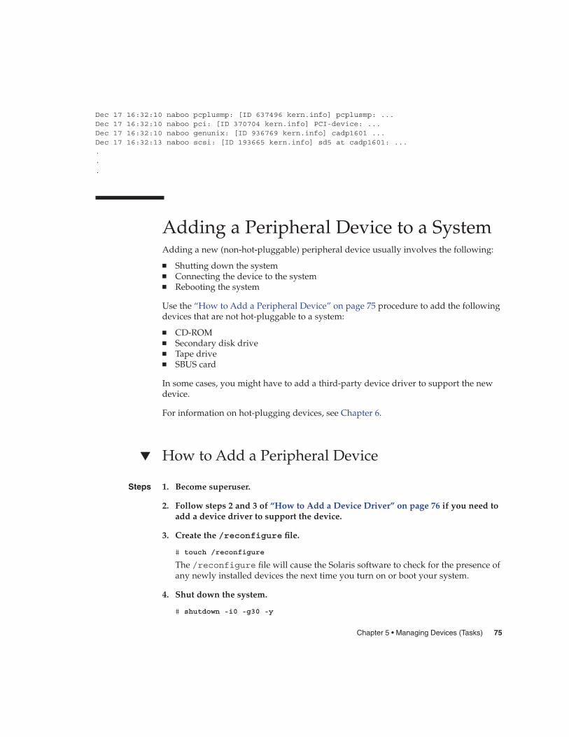
Dec 17 16:32:10 naboo pcplusmp: [ID 637496 kern.info] pcplusmp: ...Dec 17 16:32:10 naboo pci: [ID 370704 kern.info] PCI-device: ...Dec 17 16:32:10 naboo genunix: [ID 936769 kern.info] cadp1601 ...Dec 17 16:32:13 naboo scsi: [ID 193665 kern.info] sd5 at cadp1601: .....
.
Adding a Peripheral Device to a SystemAdding a new (non-hot-pluggable) peripheral device usually involves the following:
� Shutting down the system� Connecting the device to the system� Rebooting the system
Use the “How to Add a Peripheral Device” on page 75 procedure to add the followingdevices that are not hot-pluggable to a system:
� CD-ROM� Secondary disk drive� Tape drive� SBUS card
In some cases, you might have to add a third-party device driver to support the newdevice.
For information on hot-plugging devices, see Chapter 6.
� How to Add a Peripheral Device
1. Become superuser.
2. Follow steps 2 and 3 of “How to Add a Device Driver” on page 76 if you need toadd a device driver to support the device.
3. Create the /reconfigure file.
# touch /reconfigure
The /reconfigure file will cause the Solaris software to check for the presence ofany newly installed devices the next time you turn on or boot your system.
4. Shut down the system.
# shutdown -i0 -g30 -y
Steps
Chapter 5 • Managing Devices (Tasks) 75
-i0 Brings the system to the 0 init state, which is the appropriate state forturning the system power off for adding and removing devices.
-g30 Shuts the system down in 30 seconds. The default is 60 seconds.
-y Continues the system shutdown without user intervention. Otherwise,you are prompted to continue the shutdown process.
5. Select one of the following to turn off power to the system after it is shut down.
a. For SPARC platforms, it is safe to turn off power if the ok prompt isdisplayed.
b. For x86 platforms, it is safe to turn off power if the type any key tocontinue prompt is displayed.
Refer to the hardware installation guide that accompanies your system for thelocation of the power switch.
6. Turn off power to all external devices.
For the location of power switches on any peripheral devices, refer to the hardwareinstallation guides that accompany your peripheral devices.
7. Install the peripheral device, making sure that the device you are adding has adifferent target number than the other devices on the system.
You often will find a small switch located at the back of the disk for selecting thetarget number.
Refer to the hardware installation guide that accompanies the peripheral device forinformation on installing and connecting the device.
8. Turn on the power to the system.
The system boots to multiuser mode and the login prompt is displayed.
9. Verify that the peripheral device has been added by attempting to access thedevice.
For information on accessing the device, see Chapter 9.
� How to Add a Device DriverThis procedure assumes that the device has already been added to the system. If not,see “What You Need for Unsupported Devices” on page 70.
1. Become superuser.
2. Place the tape, diskette, or CD-ROM into the drive.
3. Install the driver.
Steps
76 System Administration Guide: Devices and File Systems • September 2004

# pkgadd -d device package-name
-d device Identifies the device path name that contains the package.
package-name Identifies the package name that contains the device driver.
4. Verify that the package has been added correctly.
# pkgchk package-name#
The system prompt returns with no response if the package is installed correctly.
Adding a Device Driver
The following example shows how to install and verify a package called XYZdrv.
# pkgadd XYZdrv(licensing messages displayed)...Installing XYZ Company driver as <XYZdrv>...Installation of <XYZdrv> was successful.# pkgchk XYZdrv
#
Example 5–1
Chapter 5 • Managing Devices (Tasks) 77

78 System Administration Guide: Devices and File Systems • September 2004
CHAPTER 6
Dynamically Configuring Devices(Tasks)
This chapter provides instructions for dynamically configuring devices in the Solarisenvironment. You can add, remove, or replace devices in the Solaris environmentwhile the system is still running, if the system components support hot-plugging. Ifthe system components do not support hot-plugging, you can reboot the system toreconfigure the devices.
For information on the procedures associated with dynamically configuring devices,see the following:
� “SCSI Hot-Plugging With the cfgadm Command (Task Map)” on page 83� “PCI Hot-Plugging With the cfgadm Command (Task Map)” on page 93� “Application Developer RCM Script (Task Map)” on page 100� “System Administrator RCM Script (Task Map)” on page 100
For information on hot-plugging USB devices with the cfgadm command, see“Hot-Plugging USB Devices With the cfgadm Command” on page 144.
For information about accessing devices, see Chapter 9.
Dynamic Reconfiguration andHot-PluggingHot-plugging is the ability to physically add, remove, or replace system componentswhile the system is running. Dynamic reconfiguration refers to the ability to hot-plugsystem components. This term also refers to the general ability to move systemresources (both hardware and software) around in the system or to disable them insome way without physically removing them from the system.
You can hot-plug the following devices with the cfgadm command:
79

� USB devices on SPARC and x86 platforms� SCSI devices on SPARC and x86 platforms� PCI devices on x86 platforms
Features of the cfgadm command include the following:
� Displaying system component status� Testing system components� Changing component configurations� Displaying configuration help messages
The benefit of using the cfgadm command to reconfigure systems components is thatyou can add, remove, or replace components while the system is running. An addedbenefit is that the cfgadm command guides you through the steps needed to add,remove, or replace system components.
For step-by-step instructions on hot-plugging SCSI components, see cfgadm(1M) and“SCSI Hot-Plugging With the cfgadm Command” on page 84. For step-by-stepinstructions on hot-plugging PCI adapter cards on x86 based systems, see “x86: PCIHot-Plugging With the cfgadm Command” on page 94.
Note – Not all SCSI and PCI controllers support hot-plugging with the cfgadmcommand.
As part of Sun’s high availability strategy, dynamic reconfiguration is expected to beused in conjunction with additional layered products, such as alternate pathing orfail-over software. Both products provide fault tolerance in the event of a devicefailure.
Without any high availability software, you can replace a failed device by manuallystopping the appropriate applications, unmounting noncritical file systems, and thenproceeding with the add or remove operations.
Note – For information about hot-plugging devices on your specific hardwareconfiguration, such as enterprise-level systems, please refer to your hardwareconfiguration documentation.
Attachment PointsThe cfgadm command displays information about attachment points, which arelocations in the system where dynamic reconfiguration operations can occur.
An attachment point consists of the following:
� An occupant, which represents a hardware component that can be configured intothe system
80 System Administration Guide: Devices and File Systems • September 2004

� A receptacle, which is the location that accepts the occupant
Attachment points are represented by logical and physical attachment point IDs(Ap_Ids). The physical Ap_Id is the physical pathname of the attachment point. Thelogical Ap_Id is a user-friendly alternative for the physical Ap_Id. For moreinformation on Ap_Ids, refer to cfgadm(1M).
The logical Ap_Id for a SCSI Host Bus Adapter (HBA), or SCSI controller, is usuallyrepresented by the controller number, such as c0.
In cases where no controller number has been assigned to a SCSI HBA, then aninternally-generated unique identifier is provided. An example of a unique identifierfor a SCSI controller is the following:
fas1:scsi
The logical Ap_Id for a SCSI device usually looks like this:
HBA-logical-apid::device-identifier
In the following example, c0 is the logical Ap_Id for the SCSI HBA:
c0::dsk/c0t3d0
The device identifier is typically derived from the logical device name for the device inthe /dev directory. For example, a tape device with logical device name,/dev/rmt/1, has the following logical Ap_Id:
c0::rmt/1
If a logical Ap_Id of a SCSI device cannot be derived from the logical name in the/dev directory, then an internally-generated unique identifier is provided. Anexample of an identifier for the /dev/rmt/1 tape device is the following:
c0::st4
For more information on SCSI Ap_Ids, refer to cfgadm_scsi(1M).
The cfgadm command represents all resources and dynamic reconfigurationoperations in terms of a common set of states (such as configured, unconfigured) andoperations (connect, configure, unconfigure, and so on). For more information on thesecommon states and operations, see cfgadm(1M).
The receptacle and occupant states for the SCSI HBA attachment points are as follows:
Receptacle State Description Occupant State Description
empty N/A for SCSI HBA configured One or more devicesconfigured on the bus
Chapter 6 • Dynamically Configuring Devices (Tasks) 81

Receptacle State Description Occupant State Description
disconnected Bus quiesced unconfigured No devices configured
connected Bus active
Receptacle and occupant states for SCSI device attachment points are as follows:
Receptacle State Description Occupant State Description
empty N/A for SCSI devices configured Device is configured
disconnected Bus quiesced unconfigured Device is notconfigured
connected Bus active
The state of SCSI attachment points is unknown unless there is special hardware toindicate otherwise. For instructions on displaying SCSI component information, see“How to Display Information About SCSI Devices” on page 84.
x86: Detaching PCI Adapter CardsA PCI adapter card that is hosting nonvital system resources can be removed if thedevice driver supports hot-plugging. A PCI adapter card is not detachable if it is avital system resource. For a PCI adapter card to be detachable the following conditionsmust be met:
� The device driver must support hot-plugging.� Critical resources must be accessible through an alternate pathway.
For example, if a system has only one Ethernet card installed in it, the Ethernet cardcannot be detached without losing the network connection. This detachment requiresadditional layered software support to keep the network connection active.
x86: Attaching PCI Adapter CardsA PCI adapter card can be added to the system as long as the following conditions aremet:
� There are slots available.� The device driver supports hot-plugging for this adapter card.
For step-by-step instructions on adding or removing a PCI adapter card, see “x86: PCIHot-Plugging With the cfgadm Command” on page 94.
82 System Administration Guide: Devices and File Systems • September 2004

SCSI Hot-Plugging With the cfgadmCommand (Task Map)
Task Description For Instructions
1. Display information aboutSCSI devices
Display information aboutSCSI controllers and devices.
“How to Display InformationAbout SCSI Devices” on page84
2. Unconfigure a SCSIcontroller
Unconfigure a SCSI controller. “How to Unconfigure a SCSIController” on page 85
3. Configure a SCSI controller Configure a SCSI controllerthat was previouslyunconfigured.
“How to Configure a SCSIController” on page 85
4. Configure a SCSI device Configure a specific SCSIdevice.
“How to Configure a SCSIDevice” on page 86
5. Disconnect a SCSI controller Disconnect a specific SCSIcontroller.
“How to Disconnect a SCSIController” on page 87
6. Connect a SCSI controller Connect a specific SCSIcontroller that was previouslydisconnected.
“SPARC: How to Connect aSCSI Controller” on page 88
7. Add a SCSI device to a SCSIbus
Add a specific SCSI device toa SCSI bus.
“SPARC: How to Add a SCSIDevice to a SCSI Bus”on page 88
8. Replace an identical deviceon a SCSI controller
Replace a device on the SCSIbus with another device of thesame type.
“SPARC: How to Replace anIdentical Device on a SCSIController” on page 89
9. Remove a SCSI device Remove a SCSI device fromthe system.
“SPARC: How to Remove aSCSI Device” on page 90
10. Troubleshooting SCSIconfiguration problems
Resolve a failed SCSIunconfigure operation.
“How to Resolve a FailedSCSI Unconfigure Operation”on page 93
Chapter 6 • Dynamically Configuring Devices (Tasks) 83

SCSI Hot-Plugging With the cfgadmCommandThis section describes various SCSI hot-plugging procedures that you can performwith the cfgadm command.
These procedures use specific devices as examples to illustrate how to use the cfgadmcommand to hot-plug SCSI components. The device information that you supply, andthat the cfgadm command displays, depends on your system configuration.
� How to Display Information About SCSI DevicesThe following procedure uses SCSI controllers c0 and c1 and the devices that areattached to them as examples of the type of device configuration information that youcan display with the cfgadm command.
Note – If the SCSI device is not supported by the cfgadm command, it does notdisplay in the cfgadm command output.
1. Become superuser.
2. Display information about attachment points on the system.
# cfgadm -lAp_Id Type Receptacle Occupant Conditionc0 scsi-bus connected configured unknown
c1 scsi-bus connected configured unknown
In this example, c0 and c1 represent two SCSI controllers.
3. Display information about a system’s SCSI controllers and their attacheddevices.
# cfgadm -alAp_Id Type Receptacle Occupant Conditionc0 scsi-bus connected configured unknownc0::dsk/c0t0d0 disk connected configured unknownc0::rmt/0 tape connected configured unknownc1 scsi-bus connected configured unknownc1::dsk/c1t3d0 disk connected configured unknown
c1::dsk/c1t4d0 unavailable connected unconfigured unknown
Steps
84 System Administration Guide: Devices and File Systems • September 2004

Note – The cfgadm -l commands displays information about SCSI HBAs but notSCSI devices. Use the cfgadm -al command to display information about SCSIdevices such as disk and tapes.
� How to Unconfigure a SCSI ControllerThe following procedure uses SCSI controller c1 as an example of unconfiguring aSCSI controller.
1. Become superuser.
2. Unconfigure a SCSI controller.
# cfgadm -c unconfigure c1
3. Verify that the SCSI controller is unconfigured.
# cfgadm -alAp_Id Type Receptacle Occupant Conditionc0 scsi-bus connected configured unknownc0::dsk/c0t0d0 disk connected configured unknownc0::rmt/0 tape connected configured unknown
c1 scsi-bus connected unconfigured unknown
Notice that the Occupant column for c1 specifies unconfigured, indicating thatthe SCSI bus has no configured occupants.
If the unconfigure operation fails, see “How to Resolve a Failed SCSI UnconfigureOperation” on page 93.
� How to Configure a SCSI ControllerThe following procedure uses SCSI controller c1 as an example of configuring a SCSIcontroller.
1. Become superuser.
2. Configure a SCSI controller.
# cfgadm -c configure c1
3. Verify that the SCSI controller is configured.
# cfgadm -alAp_Id Type Receptacle Occupant Conditionc0 scsi-bus connected configured unknown
Steps
Steps
Chapter 6 • Dynamically Configuring Devices (Tasks) 85

c0::dsk/c0t0d0 disk connected configured unknownc0::rmt/0 tape connected configured unknownc1 scsi-bus connected configured unknownc1::dsk/c1t3d0 disk connected configured unknown
c1::dsk/c1t4d0 unavailable connected unconfigured unknown
The previous unconfigure procedure removed all devices on the SCSI bus. Now allthe devices are configured back into the system.
� How to Configure a SCSI DeviceThe following procedure uses SCSI disk c1t4d0 as an example of configuring a SCSIdevice.
1. Become superuser.
2. Identify the device to be configured.
# cfgadm -alAp_Id Type Receptacle Occupant Conditionc0 scsi-bus connected configured unknownc0::dsk/c0t0d0 disk connected configured unknownc0::rmt/0 tape connected configured unknownc1 scsi-bus connected configured unknownc1::dsk/c1t3d0 disk connected configured unknown
c1::dsk/c1t4d0 unavailable connected unconfigured unknown
3. Configure the SCSI device.
# cfgadm -c configure c1::dsk/c1t4d0
4. Verify that the SCSI device is configured.
# cfgadm -alAp_Id Type Receptacle Occupant Conditionc0 scsi-bus connected configured unknownc0::dsk/c0t0d0 disk connected configured unknownc0::rmt/0 tape connected configured unknownc1 scsi-bus connected configured unknownc1::dsk/c1t3d0 disk connected configured unknown
c1::dsk/c1t4d0 disk connected configured unknown
Steps
86 System Administration Guide: Devices and File Systems • September 2004

� How to Disconnect a SCSI Controller
Caution – Disconnecting a SCSI device must be done with caution, particularly whenyou are dealing with controllers for disks that contain critical file systems such as root(/), usr, var, and the swap partition. The dynamic reconfiguration software cannotdetect all cases where a system hang might result. Use this procedure with caution.
The following procedure uses SCSI controller c1 as an example of disconnecting aSCSI device.
1. Become superuser.
2. Verify that the device is connected before you disconnect it.
# cfgadm -alAp_Id Type Receptacle Occupant Conditionc0 scsi-bus connected configured unknownc0::dsk/c0t0d0 disk connected configured unknownc0::rmt/0 tape connected configured unknownc1 scsi-bus connected configured unknownc1::dsk/c1t3d0 disk connected configured unknown
c1::dsk/c1t4d0 disk connected configured unknown
3. Disconnect the SCSI controller.
# cfgadm -c disconnect c1WARNING: Disconnecting critical partitions may cause system hang.
Continue (yes/no)? y
Caution – This command suspends all I/O activity on the SCSI bus until thecfgadm -c connect command is used. The cfgadm command does some basicchecking to prevent critical partitions from being disconnected, but it cannot detectall cases. Inappropriate use of this command can result in a system hang and couldrequire a system reboot.
4. Verify that the SCSI bus is disconnected.
# cfgadm -alAp_Id Type Receptacle Occupant Conditionc0 scsi-bus connected configured unknownc0::dsk/c0t0d0 disk connected configured unknownc0::rmt/0 tape connected configured unknownc1 unavailable disconnected configured unknownc1::dsk/c1t10d0 unavailable disconnected configured unknown
c1::dsk/c1t4d0 unavailable disconnected configured unknown
The controller and all the devices that are attached to it are disconnected from thesystem.
Steps
Chapter 6 • Dynamically Configuring Devices (Tasks) 87

� SPARC: How to Connect a SCSI ControllerThe following procedure uses SCSI controller c1 as an example of connecting a SCSIcontroller.
1. Become superuser.
2. Verify that the device is disconnected before you connect it.
# cfgadm -alAp_Id Type Receptacle Occupant Conditionc0 scsi-bus connected configured unknownc0::dsk/c0t0d0 disk connected configured unknownc0::rmt/0 tape connected configured unknownc1 unavailable disconnected configured unknownc1::dsk/c1t10d0 unavailable disconnected configured unknown
c1::dsk/c1t4d0 unavailable disconnected configured unknown
3. Connect the SCSI controller.
# cfgadm -c connect c1
4. Verify that the SCSI controller is connected.
# cfgadm -alAp_Id Type Receptacle Occupant Conditionc0 scsi-bus connected configured unknownc0::dsk/c0t0d0 disk connected configured unknownc0::rmt/0 tape connected configured unknownc1 scsi-bus connected configured unknownc1::dsk/c1t3d0 disk connected configured unknown
c1::dsk/c1t4d0 disk connected configured unknown
� SPARC: How to Add a SCSI Device to a SCSI BusSCSI controller c1 provides an example of how to add a SCSI device to a SCSI bus.
Note – When you add devices, you specify the Ap_Id of the SCSI HBA (controller) towhich the device is attached, not the Ap_Id of the device itself.
1. Become superuser.
2. Identify the current SCSI configuration.
# cfgadm -alAp_Id Type Receptacle Occupant Conditionc0 scsi-bus connected configured unknownc0::dsk/c0t0d0 disk connected configured unknown
Steps
Steps
88 System Administration Guide: Devices and File Systems • September 2004

c0::rmt/0 tape connected configured unknownc1 scsi-bus connected configured unknown
c1::dsk/c1t3d0 disk connected configured unknown
3. Add the SCSI device to the SCSI bus.
# cfgadm -x insert_device c1Adding device to SCSI HBA: /devices/sbus@1f,0/SUNW,fas@1,8800000
This operation will suspend activity on SCSI bus: c1
a. Type y at the Continue (yes/no)? prompt to proceed.
Continue (yes/no)? ySCSI bus quiesced successfully.
It is now safe to proceed with hotplug operation.
I/O activity on the SCSI bus is suspended while the hot-plug operation is inprogress.
b. Connect the device and then power it on.
c. Type y at the Enter y if operation is complete or n to abort(yes/no)? prompt.
Enter y if operation is complete or n to abort (yes/no)? y
4. Verify that the device has been added.
# cfgadm -alAp_Id Type Receptacle Occupant Conditionc0 scsi-bus connected configured unknownc0::dsk/c0t0d0 disk connected configured unknownc0::rmt/0 tape connected configured unknownc1 scsi-bus connected configured unknownc1::dsk/c1t3d0 disk connected configured unknown
c1::dsk/c1t4d0 disk connected configured unknown
A new disk has been added to controller c1.
� SPARC: How to Replace an Identical Device on aSCSI ControllerThe following procedure uses SCSI disk c1t4d0 as an example of replacing anidentical device on a SCSI controller.
1. Become superuser.
2. Identify the current SCSI configuration.
# cfgadm -alAp_Id Type Receptacle Occupant Conditionc0 scsi-bus connected configured unknown
Steps
Chapter 6 • Dynamically Configuring Devices (Tasks) 89

c0::dsk/c0t0d0 disk connected configured unknownc0::rmt/0 tape connected configured unknownc1 scsi-bus connected configured unknownc1::dsk/c1t3d0 disk connected configured unknown
c1::dsk/c1t4d0 disk connected configured unknown
3. Replace a device on the SCSI bus with another device of the same type.
# cfgadm -x replace_device c1::dsk/c1t4d0Replacing SCSI device: /devices/sbus@1f,0/SUNW,fas@1,8800000/sd@4,0
This operation will suspend activity on SCSI bus: c1
a. Type y at the Continue (yes/no)? prompt to proceed.
I/O activity on the SCSI bus is suspended while the hot-plug operation is inprogress.
Continue (yes/no)? ySCSI bus quiesced successfully.
It is now safe to proceed with hotplug operation.
b. Power off the device to be removed and remove it.
c. Add the replacement device. Then, power it on.
The replacement device should be of the same type and at the same address(target and lun) as the device to be removed
d. Type y at the Enter y if operation is complete or n to abort(yes/no)? prompt.
Enter y if operation is complete or n to abort (yes/no)? y
4. Verify that the device has been replaced.
# cfgadm -alAp_Id Type Receptacle Occupant Conditionc0 scsi-bus connected configured unknownc0::dsk/c0t0d0 disk connected configured unknownc0::rmt/0 tape connected configured unknownc1 scsi-bus connected configured unknownc1::dsk/c1t3d0 disk connected configured unknown
c1::dsk/c1t4d0 disk connected configured unknown
� SPARC: How to Remove a SCSI DeviceThe following procedure uses SCSI disk c1t4d0 as an example of removing a deviceon a SCSI controller.
1. Become superuser.
2. Identify the current SCSI configuration.
Steps
90 System Administration Guide: Devices and File Systems • September 2004

# cfgadm -alAp_Id Type Receptacle Occupant Conditionc0 scsi-bus connected configured unknownc0::dsk/c0t0d0 disk connected configured unknownc0::rmt/0 tape connected configured unknownc1 scsi-bus connected configured unknownc1::dsk/c1t3d0 disk connected configured unknown
c1::dsk/c1t4d0 disk connected configured unknown
3. Remove the SCSI device from the system.
# cfgadm -x remove_device c1::dsk/c1t4d0Removing SCSI device: /devices/sbus@1f,0/SUNW,fas@1,8800000/sd@4,0
This operation will suspend activity on SCSI bus: c1
a. Type y at the Continue (yes/no)? prompt to proceed.
Continue (yes/no)? ySCSI bus quiesced successfully.
It is now safe to proceed with hotplug operation.
I/O activity on the SCSI bus is suspended while the hot-plug operation is inprogress.
b. Power off the device to be removed and remove it.
c. Type y at the Enter y if operation is complete or n to abort(yes/no)? prompt.
Enter y if operation is complete or n to abort (yes/no)? y
4. Verify that the device has been removed from the system.
# cfgadm -alAp_Id Type Receptacle Occupant Conditionc0 scsi-bus connected configured unknownc0::dsk/c0t0d0 disk connected configured unknownc0::rmt/0 tape connected configured unknownc1 scsi-bus connected configured unknown
c1::dsk/c1t3d0 disk connected configured unknown
SPARC: Troubleshooting SCSI ConfigurationProblemsThis section provides error messages and possible solutions for troubleshooting SCSIconfiguration problems. For more information on troubleshooting SCSI configurationproblems, see cfgadm(1M).
Error Message
cfgadm: Component system is busy, try again: failed to offline:device path
Resource Information
Chapter 6 • Dynamically Configuring Devices (Tasks) 91
------------------ --------------------------
/dev/dsk/c1t0d0s0 mounted filesystem "/file-system"
CauseYou attempted to remove or replace a device with a mounted file system.
SolutionUnmount the file system that is listed in the error message and retry the cfgadmoperation.
If you use the cfgadm command to remove a system resource, such as a swap deviceor a dedicated dump device, an error messages similar to the following is displayed ifthe system resource is still active.
Error Message
cfgadm: Component system is busy, try again: failed to offline:device path
Resource Information------------------ --------------------------
/dev/dsk/device-name swap area
CauseYou attempted to remove or replace one or more configured swap areas.
SolutionUnconfigure the swap areas on the device that is specified and retry the cfgadmoperation.
Error Message
cfgadm: Component system is busy, try again: failed to offline:device path
Resource Information------------------ --------------------------
/dev/dsk/device-name dump device (swap)
CauseYou attempted to remove or replace a dump device that is configured on a swaparea.
SolutionUnconfigure the dump device that is configured on the swap area and retry thecfgadm operation.
Error Message
cfgadm: Component system is busy, try again: failed to offline:device path
Resource Information------------------ --------------------------
/dev/dsk/device-name dump device (dedicated)
CauseYou attempted to remove or replace a dedicated dump device.
92 System Administration Guide: Devices and File Systems • September 2004

SolutionUnconfigure the dedicate dump device and retry the cfgadm operation.
� How to Resolve a Failed SCSI UnconfigureOperationUse this procedure if one or more target devices are busy and the SCSI unconfigureoperation fails. Otherwise, future dynamic reconfiguration operations on thiscontroller and target devices will fail with a dr in progress message.
1. Become superuser, if not done already.
2. Type the following command to reconfigure the controller.
# cfgadm -c configure device-name
PCI Hot-Plugging With the cfgadmCommand (Task Map)
Task Description For Instructions
1. Display PCI SlotConfiguration Information
Display the status of PCIhot-pluggable devices andslots on the system.
“x86: How to Display PCI SlotConfiguration Information”on page 94
2. Remove a PCI adapter card Unconfigure the card,disconnect power from theslot, and remove the cardfrom the system.
“x86: How to Remove a PCIAdapter Card” on page 95
3. Add a PCI adapter card Insert the adapter card into ahot-pluggable slot, connectpower to the slot, andconfigure the card.
“x86: How to Add a PCIAdapter Card” on page 96
4. Troubleshooting PCIconfiguration problems
Identify error message andpossible solutions to resolvePCI configuration problems.
“x86: Troubleshooting PCIConfiguration Problems”on page 97
Steps
Chapter 6 • Dynamically Configuring Devices (Tasks) 93

x86: PCI Hot-Plugging With the cfgadmCommandThis section provides step-by-step instructions for hot-plugging PCI adapter cards onx86 based systems.
In the examples, only PCI attachment points are listed, for brevity. The attachmentpoints that are displayed on your system depend on your system configuration.
� x86: How to Display PCI Slot ConfigurationInformationThe cfgadm command displays the status of PCI hot-pluggable devices and slots on asystem. For more information, see cfgadm(1M).
1. Become superuser.
2. Display PCI slot configuration information.
# cfgadmAp_Id Type Receptacle Occupant Conditionpci1:hpc0_slot0 unknown empty unconfigured unknownpci1:hpc0_slot1 unknown empty unconfigured unknownpci1:hpc0_slot2 unknown empty unconfigured unknownpci1:hpc0_slot3 ethernet/hp connected configured ok
pci1:hpc0_slot4 unknown empty unconfigured unknown
Display specific PCI device information.
# cfgadm -s "cols=ap_id:type:info" pciAp_Id Type Informationpci1:hpc0_slot0 unknown Slot 7pci1:hpc0_slot1 unknown Slot 8pci1:hpc0_slot2 unknown Slot 9pci1:hpc0_slot3 ethernet/hp Slot 10
pci1:hpc0_slot4 unknown Slot 11
The logical Ap_Id, pci1:hpc0_slot0, is the logical Ap_Id for hot-pluggableslot, Slot 7. The component hpc0 indicates the hot-pluggable adapter card forthis slot, and pci1 indicates the PCI bus instance. The Type field indicates thetype of PCI adapter card that is present in the slot.
Steps
94 System Administration Guide: Devices and File Systems • September 2004

� x86: How to Remove a PCI Adapter Card
1. Become superuser.
2. Determine which slot the PCI adapter card is in.
# cfgadmAp_Id Type Receptacle Occupant Conditionpci1:hpc0_slot0 unknown empty unconfigured unknownpci1:hpc0_slot1 unknown empty unconfigured unknownpci1:hpc0_slot2 unknown empty unconfigured unknownpci1:hpc0_slot3 ethernet/hp connected configured ok
pci1:hpc0_slot4 unknown empty unconfigured unknown
3. Stop the application that has the device open.
For example, if the device is an Ethernet card, use the ifconfig command tobring down the interface and unplumb the interface.
4. Unconfigure the device.
# cfgadm -c unconfigure pci1:hpc0_slot3
5. Confirm that the device has been unconfigured.
# cfgadmAp_Id Type Receptacle Occupant Conditionpci1:hpc0_slot0 unknown empty unconfigured unknownpci1:hpc0_slot1 unknown empty unconfigured unknownpci1:hpc0_slot2 unknown empty unconfigured unknownpci1:hpc0_slot3 ethernet/hp connected unconfigured unknown
pci1:hpc0_slot4 unknown empty unconfigured unknown
6. Disconnect the power to the slot.
# cfgadm -c disconnect pci1:hpc0_slot3
7. Confirm that the device has been disconnected.
# cfgadmAp_Id Type Receptacle Occupant Conditionpci1:hpc0_slot0 unknown empty unconfigured unknownpci1:hpc0_slot1 unknown empty unconfigured unknownpci1:hpc0_slot2 unknown empty unconfigured unknownpci1:hpc0_slot3 ethernet/hp disconnected unconfigured unknown
pci1:hpc0_slot4 unknown empty unconfigured unknown
8. Open the slot latches and remove the PCI adapter card.
Steps
Chapter 6 • Dynamically Configuring Devices (Tasks) 95

� x86: How to Add a PCI Adapter Card
1. Become superuser.
2. Identify the hot-pluggable slot and open latches.
3. Insert the PCI adapter card into a hot-pluggable slot.
4. Determine which slot the PCI adapter card is in once it is inserted. Close thelatches.
# cfgadmAp_Id Type Receptacle Occupant Conditionpci1:hpc0_slot0 unknown empty unconfigured unknownpci1:hpc0_slot1 unknown empty unconfigured unknownpci1:hpc0_slot2 unknown empty unconfigured unknownpci1:hpc0_slot3 ethernet/hp disconnected unconfigured unknown
pci1:hpc0_slot4 unknown empty unconfigured unknown
5. Connect the power to the slot.
# cfgadm -c connect pci1:hpc0_slot3
6. Confirm that the slot is connected.
# cfgadmAp_Id Type Receptacle Occupant Conditionpci1:hpc0_slot0 unknown empty unconfigured unknownpci1:hpc0_slot1 unknown empty unconfigured unknownpci1:hpc0_slot2 unknown empty unconfigured unknownpci1:hpc0_slot3 ethernet/hp connected unconfigured unknown
pci1:hpc0_slot4 unknown empty unconfigured unknown
7. Configure the PCI adapter card.
# cfgadm -c configure pci1:hpc0_slot3
8. Verify the configuration of the PCI adapter card in the slot.
# cfgadmAp_Id Type Receptacle Occupant Conditionpci1:hpc0_slot0 unknown empty unconfigured unknownpci1:hpc0_slot1 unknown empty unconfigured unknownpci1:hpc0_slot2 unknown empty unconfigured unknownpci1:hpc0_slot3 ethernet/hp connected configured unknown
pci1:hpc0_slot4 unknown empty unconfigured unknown
9. Configure any supporting software if this device is a new device.
For example, if this device is an Ethernet card, use the ifconfig command to setup the interface.
Steps
96 System Administration Guide: Devices and File Systems • September 2004

x86: Troubleshooting PCI Configuration ProblemsError Message
cfgadm: Configuration operation invalid: invalid transition
CauseAn invalid transition was attempted.
SolutionCheck whether the cfgadm -c command was issued appropriately. Use thecfgadm command to check the current receptacle and occupant state and to makesure that the Ap_Id is correct.
Error Message
cfgadm: Attachment point not found
CauseThe specified attachment point was not found.
SolutionCheck whether the attachment point is correct. Use the cfgadm command todisplay a list of available attachment points. Also check the physical path to see ifthe attachment point is still there.
Note – In addition to the cfgadm command, several other commands are helpfulduring hot-pluggable operations. The prtconf command displays whether Solarisrecognizes the hardware. After adding hardware, use the prtconf command to verifythat the hardware is recognized. After a configure operation, use the prtconf -Dcommand to verify that the driver is attached to the newly installed hardware device.
Reconfiguration Coordination Manager(RCM) Script OverviewThe Reconfiguration Coordination Manager (RCM) is the framework that manages thedynamic removal of system components. By using RCM, you can register and releasesystem resources in an orderly manner.
You can use the new RCM script feature to write your own scripts to shut down yourapplications, or to cleanly release the devices from your applications during dynamicreconfiguration. The RCM framework launches a script automatically in response to areconfiguration request, if the request impacts the resources that are registered by thescript.
Chapter 6 • Dynamically Configuring Devices (Tasks) 97

You can also release resources from applications manually before you coulddynamically remove the resource. Or, you could use the cfgadm command with the-f option to force a reconfiguration operation, but this option might leave yourapplications in an unknown state. Also, the manual release of resources fromapplications commonly causes errors.
The RCM script feature simplifies and better controls the dynamic reconfigurationprocess. By creating an RCM script, you can do the following:
� Automatically release a device when you dynamically remove a device. Thisprocess also closes the device if the device is opened by an application.
� Run site-specific tasks when you dynamically remove a device from the system.
What Is an RCM Script?An RCM script is as follows:
� An executable shell script (Perl, sh, csh, or ksh) or binary program that the RCMdaemon runs. Perl is the recommended language.
� A script that runs in its own address space by using the user ID of the script fileowner.
� A script that is run by the RCM daemon when you use the cfgadm command todynamically reconfigure a system resource.
What Can an RCM Script Do?You can use an RCM script to release a device from an application when youdynamically remove a device. If the device is currently open, the RCM script alsocloses the device.
For example, an RCM script for a tape backup application can inform the tape backupapplication to close the tape drive or shut down the tape backup application.
How Does the RCM Script Process Work?You can invoke a script as follows:
$ script-name command [args ...]
A script performs the following basic steps:
1. Takes the RCM command from command-line arguments.2. Executes the command.3. Writes the results to stdout as name-value pairs.
98 System Administration Guide: Devices and File Systems • September 2004
4. Exits with the appropriate exit status.
The RCM daemon runs one instance of a script at a time. For example, if a script isrunning, the RCM daemon does not run the same script until the first script exits.
RCM Script CommandsYou must include the following RCM commands in an RCM script:
� scriptinfo - Gathers script information� register - Registers interest in resources� resourceinfo - Gathers resource information
You might include some or all of the following RCM commands:
� queryremove - Queries whether the resource can be released� preremove - Releases the resource� postremove - Provides post-resource removal notification� undoremove - Undoes the actions done in preremove
For a complete description of these RCM commands, see rcmscript(4).
RCM Script Processing EnvironmentWhen you dynamically remove a device, the RCM daemon runs the following:
� The script’s register command to gather the list of resources (device names) thatare identified in the script.
� The script’s queryremove/preremove commands prior to removing the resourceif the script’s registered resources are affected by the dynamic remove operation.
� The script’s postremove command if the remove operation succeeds. However, ifthe remove operation fails, the RCM daemon runs the script’s undoremovecommand.
RCM Script TasksThe following sections describe the RCM script tasks for application developers andsystem administrators.
Chapter 6 • Dynamically Configuring Devices (Tasks) 99
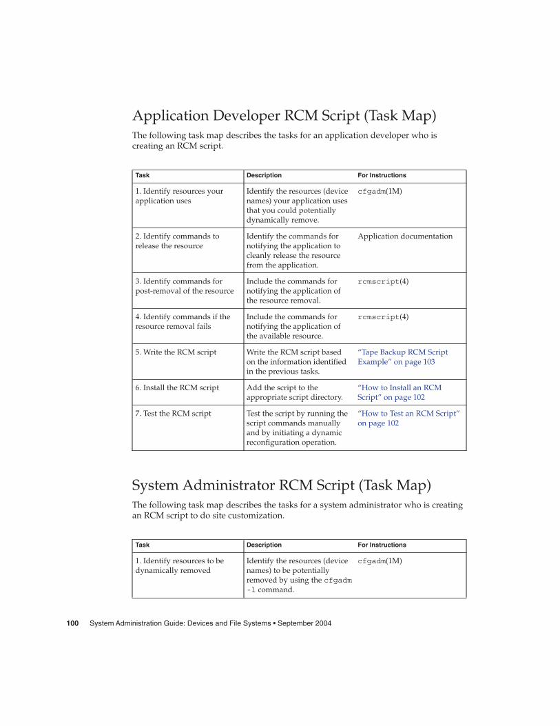
Application Developer RCM Script (Task Map)The following task map describes the tasks for an application developer who iscreating an RCM script.
Task Description For Instructions
1. Identify resources yourapplication uses
Identify the resources (devicenames) your application usesthat you could potentiallydynamically remove.
cfgadm(1M)
2. Identify commands torelease the resource
Identify the commands fornotifying the application tocleanly release the resourcefrom the application.
Application documentation
3. Identify commands forpost-removal of the resource
Include the commands fornotifying the application ofthe resource removal.
rcmscript(4)
4. Identify commands if theresource removal fails
Include the commands fornotifying the application ofthe available resource.
rcmscript(4)
5. Write the RCM script Write the RCM script basedon the information identifiedin the previous tasks.
“Tape Backup RCM ScriptExample” on page 103
6. Install the RCM script Add the script to theappropriate script directory.
“How to Install an RCMScript” on page 102
7. Test the RCM script Test the script by running thescript commands manuallyand by initiating a dynamicreconfiguration operation.
“How to Test an RCM Script”on page 102
System Administrator RCM Script (Task Map)The following task map describes the tasks for a system administrator who is creatingan RCM script to do site customization.
Task Description For Instructions
1. Identify resources to bedynamically removed
Identify the resources (devicenames) to be potentiallyremoved by using the cfgadm-l command.
cfgadm(1M)
100 System Administration Guide: Devices and File Systems • September 2004

Task Description For Instructions
2. Identify applications to bestopped
Identify the commands forstopping the applicationscleanly.
Application documentation
3. Identify commands forpre-removal and post-removalof the resource
Identify the actions to betaken before and after theresource is removed.
rcmscript(4)
4. Write the RCM script Write the RCM script basedon the information identifiedin the previous tasks.
“Tape Backup RCM ScriptExample” on page 103
5. Install the RCM script Add the script to theappropriate script directory.
“How to Install an RCMScript” on page 102
6. Test the RCM script Test the script by running thescript commands manuallyand by initiating a dynamicreconfiguration operation.
“How to Test an RCM Script”on page 102
Naming an RCM ScriptA script must be named as vendor,service where the following applies:
vendor Is the stock symbol of the vendor that provides the script, or any distinctname that identifies the vendor.
service Is the name of the service that the script represents.
Installing or Removing an RCM ScriptYou must be superuser (root) to install or remove an RCM script. Use this table todetermine where you should install your RCM script.
TABLE 6–1 RCM Script Directories
Directory Location Script Type
/etc/rcm/scripts Scripts for specific systems
/usr/platform/‘uname-i‘/lib/rcm/scripts
Scripts for a specific hardware implementation
/usr/platform/‘uname-m‘/lib/rcm/scripts
Scripts for a specific hardware class
/usr/lib/rcm/scripts Scripts for any hardware
Chapter 6 • Dynamically Configuring Devices (Tasks) 101
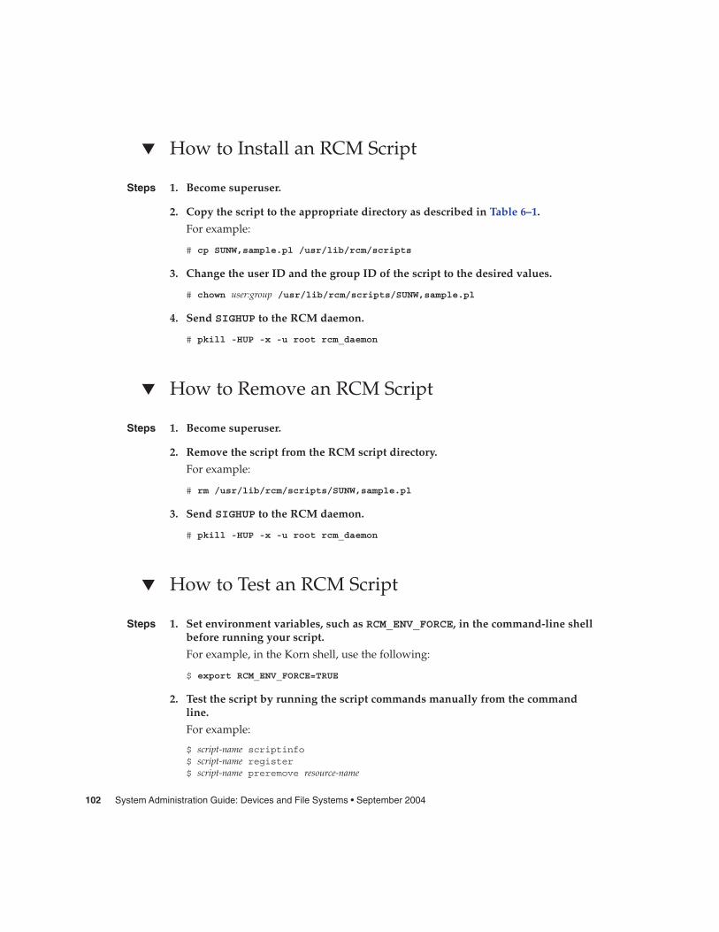
� How to Install an RCM Script
1. Become superuser.
2. Copy the script to the appropriate directory as described in Table 6–1.
For example:
# cp SUNW,sample.pl /usr/lib/rcm/scripts
3. Change the user ID and the group ID of the script to the desired values.
# chown user:group /usr/lib/rcm/scripts/SUNW,sample.pl
4. Send SIGHUP to the RCM daemon.
# pkill -HUP -x -u root rcm_daemon
� How to Remove an RCM Script
1. Become superuser.
2. Remove the script from the RCM script directory.
For example:
# rm /usr/lib/rcm/scripts/SUNW,sample.pl
3. Send SIGHUP to the RCM daemon.
# pkill -HUP -x -u root rcm_daemon
� How to Test an RCM Script
1. Set environment variables, such as RCM_ENV_FORCE, in the command-line shellbefore running your script.
For example, in the Korn shell, use the following:
$ export RCM_ENV_FORCE=TRUE
2. Test the script by running the script commands manually from the commandline.
For example:
$ script-name scriptinfo$ script-name register$ script-name preremove resource-name
Steps
Steps
Steps
102 System Administration Guide: Devices and File Systems • September 2004

$ script-name postremove resource-name
3. Make sure each RCM script command in your script prints appropriate output tostdout.
4. Install the script in the appropriate script directory.
For more information, see “How to Install an RCM Script” on page 102.
5. Test the script by initiating a dynamic remove operation:
For example, assume your script registers the device, /dev/dsk/c1t0d0s0. Trythese commands.
$ cfgadm -c unconfigure c1::dsk/c1t0d0$ cfgadm -f -c unconfigure c1::dsk/c1t0d0
$ cfgadm -c configure c1::dsk/c1t0d0
Caution – Make sure that you are familiar with these commands because they canalter the state of the system and can cause system failures.
Tape Backup RCM Script ExampleThis example illustrates how to use an RCM script for tape backups.
What the Tape Backup RCM Script DoesThe tape backup RCM script performs the following steps:
1. Sets up a dispatch table of RCM commands.
2. Calls the dispatch routine that corresponds to the specified RCM command andexits with status 2 for unimplemented RCM commands.
3. Sets up the scriptinfo section:
rcm_script_func_info=Tape backup appl script for DR
4. Registers all tape drives in the system by printing all tape drive device names tostdout.
rcm_resource_name=/dev/rmt/$f
If an error occurs, prints the error information to stdout.
rcm_failure_reason=$errmsg
5. Sets up the resource information for the tape device.
rcm_resource_usage_info=Backup Tape Unit Number $unit
Chapter 6 • Dynamically Configuring Devices (Tasks) 103

6. Sets up the preremove information by checking if the backup application is usingthe device. If the backup application is not using the device, the dynamicreconfiguration operation continues. If the backup application is using the device,the script checks RCM_ENV_FORCE. If RCM_ENV_FORCE is set to FALSE, the scriptdenies the dynamic reconfiguration operation and prints the following message:
rcm_failure_reason=tape backup in progress pid=...
If RCM_ENV_FORCE is set to TRUE, the backup application is stopped, and thereconfiguration operation proceeds.
Outcomes of the Tape Backup Reconfiguration ScenariosHere are the various outcomes if you use the cfgadm command to remove a tapedevice without the RCM script.
� If you use the cfgadm command and the backup application is not using the tapedevice, the operation succeeds.
� If you use the cfgadm command and the backup application is using the tapedevice, the operation fails.
Here are the various outcomes if you use the cfgadm command to remove a tapedevice with the RCM script.
� If you use the cfgadm command and the backup application is not using the tapedevice, the operation succeeds.
� If you use the cfgadm command without the -f option and the backupapplication is using the tape device, the operation fails with an error messagesimilar to the following:
tape backup in progress pid=...
� If you use the cfgadm -f command and the backup application is using the tapedevice, the script stops the backup application and the cfgadm operation succeeds.
Example—Tape Backup RCM Script#! /usr/bin/perl -w
## A sample site customization RCM script.## When RCM_ENV_FORCE is FALSE this script indicates to RCM that it cannot# release the tape drive when the tape drive is being used for backup.## When RCM_ENV_FORCE is TRUE this script allows DR removing a tape drive# when the tape drive is being used for backup by killing the tape# backup application.#
104 System Administration Guide: Devices and File Systems • September 2004

use strict;
my ($cmd, %dispatch);$cmd = shift(@ARGV);
# dispatch table for RCM commands%dispatch = (
"scriptinfo" => \&do_scriptinfo,"register" => \&do_register,"resourceinfo" => \&do_resourceinfo,"queryremove" => \&do_preremove,"preremove" => \&do_preremove
);
if (defined($dispatch{$cmd})) {&{$dispatch{$cmd}};
} else {exit (2);
}
sub do_scriptinfo{
print "rcm_script_version=1\n";print "rcm_script_func_info=Tape backup appl script for DR\n";exit (0);
}
sub do_register{
my ($dir, $f, $errmsg);
$dir = opendir(RMT, "/dev/rmt");if (!$dir) {
$errmsg = "Unable to open /dev/rmt directory: $!";print "rcm_failure_reason=$errmsg\n";exit (1);
}
while ($f = readdir(RMT)) {# ignore hidden files and multiple names for the same deviceif (($f !~ /^\./) && ($f =~ /^[0-9]+$/)) {
print "rcm_resource_name=/dev/rmt/$f\n";}
}
closedir(RMT);exit (0);
}sub do_resourceinfo
{my ($rsrc, $unit);
$rsrc = shift(@ARGV);if ($rsrc =~ /^\/dev\/rmt\/([0-9]+)$/) {
Chapter 6 • Dynamically Configuring Devices (Tasks) 105
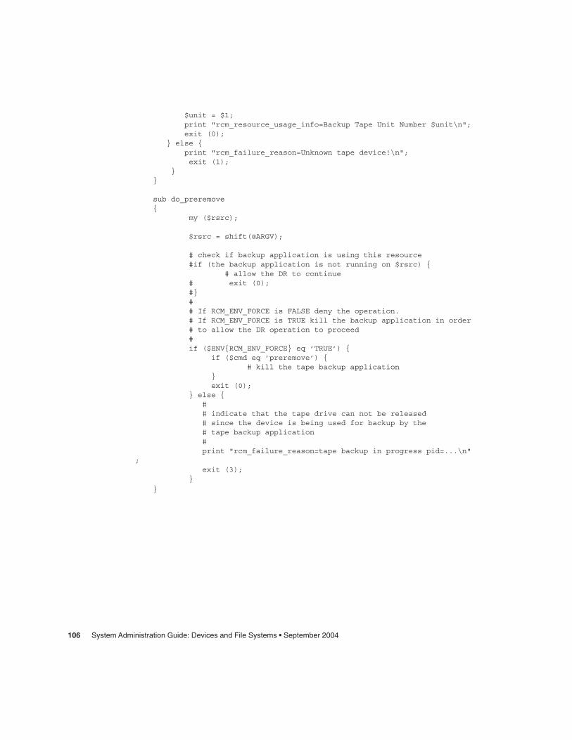
$unit = $1;print "rcm_resource_usage_info=Backup Tape Unit Number $unit\n";exit (0);
} else {print "rcm_failure_reason=Unknown tape device!\n";exit (1);
}}
sub do_preremove{
my ($rsrc);
$rsrc = shift(@ARGV);
# check if backup application is using this resource#if (the backup application is not running on $rsrc) {
# allow the DR to continue# exit (0);#}## If RCM_ENV_FORCE is FALSE deny the operation.# If RCM_ENV_FORCE is TRUE kill the backup application in order# to allow the DR operation to proceed#if ($ENV{RCM_ENV_FORCE} eq ’TRUE’) {
if ($cmd eq ’preremove’) {# kill the tape backup application
}exit (0);
} else {## indicate that the tape drive can not be released# since the device is being used for backup by the# tape backup application#print "rcm_failure_reason=tape backup in progress pid=...\n"
;exit (3);
}
}
106 System Administration Guide: Devices and File Systems • September 2004

CHAPTER 7
Using USB Devices (Overview)
This chapter provides an overview of Universal Serial Bus (USB) devices in the Solarisenvironment.
This is a list of the overview information in this chapter.
� “What’s New in USB Devices?” on page 107� “Overview of USB Devices” on page 114� “About USB in the Solaris Environment” on page 118
For step-by-step instructions on using USB devices in the Solaris environment, seeChapter 8.
For general information about dynamic reconfiguration and hot-plugging, seeChapter 6.
For information on configuring USB printers, see “What’s New in Printing?” in SystemAdministration Guide: Advanced Administration.
What’s New in USB Devices?The following sections describe USB device enhancements in this Solaris release.
USB Dual FrameworkThe USBA framework, found in the Solaris 9 12/03 release, was originally developedfor USB 1.1 devices. A new framework, called USBA 1.0, was created to meet moredemanding requirements of USB 2.0 devices. The framework operates USB 1.1 devicesas well. This Solaris release provides both frameworks, hence the name dual framework.
107

The purpose of the dual framework is to facilitate a smoother transition from theoriginal framework to the newer framework. The original USBA framework operatesdevices connected to a system’s USB 1.1 ports, while the new USBA 1.0 frameworkoperates devices connected to a system’s USB 2.0 ports. All Sun motherboard ports areUSB 1.1 ports, while most PCI card ports support USB 2.0.
For specific details on the how the USB dual framework works, go tohttp://www.sun.com/desktop/whitepapers.html.
USB Framework Compatibility IssuesA driver written for one USB framework will not work on the other USB framework.Most Sun-supplied USB drivers provide versions for both frameworks.
Compatibility problems might occur if you attempt to plug a USB device into a port,directed by a framework that does not recognize a proper driver for that devicebecause the driver is incompatible. When a framework tries to attach aframework-incompatible driver for a device, you will see console messages similar tothe following:
The driver for device binding name is not for USBA1.0
This message will appear, for example, when a device operated by a non-Sun driver,which is compatible with USBA 1.0 framework, is plugged into a port supported bythe original USBA framework. The USBA 1.0 framework recognizes the device andtries to map the correct driver, but the driver is rejected because it is incompatible withthe framework operating the port.
For information on identifying your USB framework configuration, see “How toDisplay USB Device Information (prtconf)” on page 128.
Solaris Support for USB DevicesThe following table describes Solaris support for USB 1.1 and USB 2.0 devices:
Solaris 8 HW* Releases Solaris 9 Releases
USB 1.1 SPARC and x86 SPARC and x86
USB 1.1 audio devices Not supported on a USB 2.0hub
Not supported on a USB 2.0hub
USB 2.0 SPARC SPARC and x86 (Solaris 94/04)
USB 2.0 audio devices Not supported Not supported
108 System Administration Guide: Devices and File Systems • September 2004
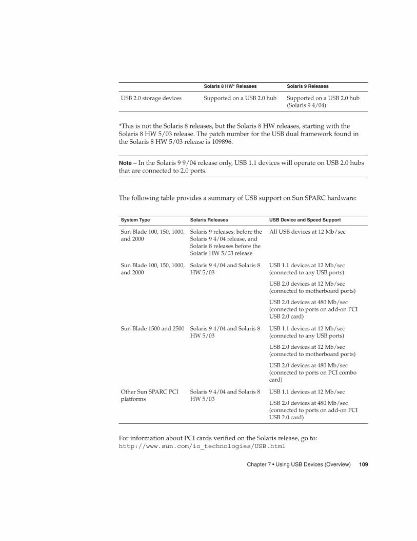
Solaris 8 HW* Releases Solaris 9 Releases
USB 2.0 storage devices Supported on a USB 2.0 hub Supported on a USB 2.0 hub(Solaris 9 4/04)
*This is not the Solaris 8 releases, but the Solaris 8 HW releases, starting with theSolaris 8 HW 5/03 release. The patch number for the USB dual framework found inthe Solaris 8 HW 5/03 release is 109896.
Note – In the Solaris 9 9/04 release only, USB 1.1 devices will operate on USB 2.0 hubsthat are connected to 2.0 ports.
The following table provides a summary of USB support on Sun SPARC hardware:
System Type Solaris Releases USB Device and Speed Support
Sun Blade 100, 150, 1000,and 2000
Solaris 9 releases, before theSolaris 9 4/04 release, andSolaris 8 releases before theSolaris HW 5/03 release
All USB devices at 12 Mb/sec
Sun Blade 100, 150, 1000,and 2000
Solaris 9 4/04 and Solaris 8HW 5/03
USB 1.1 devices at 12 Mb/sec(connected to any USB ports)
USB 2.0 devices at 12 Mb/sec(connected to motherboard ports)
USB 2.0 devices at 480 Mb/sec(connected to ports on add-on PCIUSB 2.0 card)
Sun Blade 1500 and 2500 Solaris 9 4/04 and Solaris 8HW 5/03
USB 1.1 devices at 12 Mb/sec(connected to any USB ports)
USB 2.0 devices at 12 Mb/sec(connected to motherboard ports)
USB 2.0 devices at 480 Mb/sec(connected to ports on PCI combocard)
Other Sun SPARC PCIplatforms
Solaris 9 4/04 and Solaris 8HW 5/03
USB 1.1 devices at 12 Mb/sec
USB 2.0 devices at 480 Mb/sec(connected to ports on add-on PCIUSB 2.0 card)
For information about PCI cards verified on the Solaris release, go to:http://www.sun.com/io_technologies/USB.html
Chapter 7 • Using USB Devices (Overview) 109

Sun Microsystems platforms that provide support for USB devices include thefollowing:
� SPARC based systems with OHCI host controllers that support USB 1.1 providelow- and full-speed devices:
� Sun Blade™ systems that run the Solaris 8 or 9 releases.� Netra™ X 1/T1 and some Sun Fire™ systems that run the Solaris 9 release.
� SPARC based systems with OHCI and EHCI host controllers, such as the Sun Blade1500 or 2500 systems, provide high-speed support for USB 2.0 devices and low-and full-speed support for USB 1.1 devices. Systems include any PCI-based sun4usystem that run the Solaris 8 HW 5/03 release or Solaris 9 4/04 release, includingthe systems listed above when they are equipped with a USB 2.0 PCI card.
� x86 based systems that run the Solaris 8 or 9 x86 Platform Edition with UHCI hostcontrollers provide USB 1.1 support.
For additional USB support information, see “Overview of USB Devices” on page 114.
SPARC: USB 2.0 FeaturesThis Solaris release includes the following USB 2.0 features:
� Better performance – Increased data throughput for devices connected to USB 2.0controllers, up to 40 times faster than USB 1.1 devices.
You will be able to take advantage of the high-speed USB protocol when accessinghigh-speed mass storage devices, such as DVDs and hard drives.
� Compatibility – Backward compatibility with 1.0 and 1.1 devices and drivers sothat you can use the same cables, connectors, and software interfaces.
For a description of USB devices and terminology, see “Overview of USB Devices”on page 114.
USB 2.0 Device Features and Compatibility IssuesUSB 2.0 devices are defined as high-speed devices that follow the USB 2.0specification. You can refer to the USB 2.0 specification at http://www.usb.org.
Some of the USB devices that are supported on SPARC based and x86 based systemsin this Solaris release are as follows:
� Mass storage devices – CD-RWs, hard disks, DVD, digital cameras, Zip, diskettes,and tape drives
� Keyboard, mouse devices, speakers and microphones
� Audio devices
For a full listing of USB devices that have been verified on the Solaris release, go to:
110 System Administration Guide: Devices and File Systems • September 2004
http://www.sun.com/io_technologies/USB.html
Additional storage devices might work by modifying the scsa2usb.conf file. Formore information, see the scsa2usb(7D) man page.
Solaris USB 2.0 device support includes the following features:
� Increased USB bus speed from 12 Mbps to 480 Mbps. This increase means devicesthat support the USB 2.0 specification can run significantly faster than their USB 1.1counterparts, when they are connected to a USB 2.0 port.
A USB 2.0 port is defined on SPARC systems as follows:
� A port on a USB 2.0 PCI card� A port on a USB 2.0 hub that is connected to USB 2.0 port
� USB 2.0 is Solaris Ready on all PCI-based SPARC platforms. A USB 2.0 PCI card isneeded to provide USB 2.0 ports. For a list of USB 2.0 PCI cards that have beenverified for the Solaris release, go tohttp://www.sun.com/io_technologies/USB.html.
� USB 1.1 devices work as they have in the past, even if you have both USB 1.1 andUSB 2.0 devices on the same system.
� While USB 2.0 devices operate on a USB 1.x port, their performance is significantlybetter when connected to a USB 2.0 port.
� A USB 2.0 host controller has one high-speed Enhanced Host Controller (EHCI)and one or more low- or full-speed OpenHCI Host Controller (OHCI) embeddedcontrollers. Devices connected to a USB 2.0 port are dynamically assigned to eitheran EHCI or OHCI controller, depending on whether or not they support USB 2.0.
Note – USB 2.0 storage devices connected to a port on a USB 2.0 PCI card, and thatwere used with a prior Solaris release in the same hardware configuration, canchange device names after upgrading to this release. This change occurs becausethese devices are now seen as USB 2.0 devices and are taken over by the EHCIcontroller. The controller number, w in /dev/[r]dsk/cwtxdysz, is changed forthese devices.
For more information on USB 2.0 device support, see the ehci(7D) and usba(7D)man pages.
USB 2.0 Cables� Maximum cable length supported is 5 meters.
� Do not use cable extenders. For best results, use a self-powered hub to extend cablelength.
� For more information, go tohttp://www.usb.org/channel/training/warning/
Chapter 7 • Using USB Devices (Overview) 111

Bus-Powered DevicesBus-powered hubs use power from the USB bus to which they are connected, topower devices connected to them. Special care must be taken to not overload thesehubs, since the power these hubs offer to their downstream devices is limited.
� Do not cascade bus-powered hubs. For example, do not connect one bus-poweredhub to another bus-powered hub.
� Avoid connecting bus-powered devices to bus-powered hubs, except forlow-speed, low-power devices, such as keyboards or mice. Connectinghigh-powered devices such as disks, speakers, or microphones to a bus-poweredhub could cause power-shortages for all devices connected to that hub. Thisscenario could cause these devices to behave unpredictably.
USB Mass Storage DevicesAll USB storage devices in this Solaris release are now accessed as removable mediadevices. This change has the following advantages:
� USB storage devices with standard MS-DOS or Windows (FAT) file systems arenow supported.
� You can use the user-friendly rmformat command instead of the formatcommand to format and partition all USB storage devices. If the functionality ofthe format command is needed, use the format -e command.
� You can use the fdisk command if you need to do fdisk-style partitioning.� Non-root users can now access USB storage devices, since the root-privileged
mount command is no longer needed. The device is automatically mounted byvold and is available under the /rmdisk directory. If a new device is connectedwhile the system is down, do a reconfiguration boot with the boot -r commandso that vold recognizes the device. Note that vold does not automaticallyrecognize a hot-plugged device. If a new device is connected while the system isup, restart vold. For more information, refer to the vold(1M) andscsa2usb(7D) man pages.
� Disks with FAT file systems can be mounted and accessed. For example:
mount -F pcfs /dev/dsk/c2t0d0s0:c /mnt
� All USB storage devices are now power managed, except for those that supportLOG SENSE pages. Devices with LOG SENSE pages are usually SCSI drivesconnected through a USB-to-SCSI bridge device. In previous Solaris releases, someUSB storage devices were not power managed because they were not seen asremovable media.
� Applications might work differently with USB mass storage devices. Keep thefollowing issues in mind when using applications with USB storage devices:
� Applications might make incorrect assumptions about the size of the mediasince only smaller devices like diskettes and Zip drives were removablepreviously.
112 System Administration Guide: Devices and File Systems • September 2004

� Requests by applications to eject media on devices where this would beinapplicable, such as a hard drive, will succeed and do nothing.
� If you prefer the behavior in previous Solaris releases where not all USB massstorage were treated as removable media devices, then you can force the oldbehavior by updating the /kernel/drv/scsa2usb.conf file.
For more information on using USB mass storage devices, see the scsa2usb(7D)man page.
Troubleshooting Tips for USB Mass Storage DevicesKeep the following tips in mind if you have problems adding or removing a USB massstorage device.
� If USB devices are added or removed when the system is down, you must performa reconfiguration boot.
ok boot -r
If you have problems accessing a device that was connected while the system isrunning, try the following command:
# devfsadm
� Do not move devices around if the system has been powered down by a suspendoperation. For more information, see “SPARC: USB Power Management” on page120.
� If a device has been hot removed while in use by applications and is no longeravailable, then stop the applications. Use the prtconf command to see whetherthe device node has been removed.
SPARC: USB Driver EnhancementsThis section describes USB driver enhancements in this Solaris release.
� New generic USB driver – USB devices can now be accessed and manipulated byapplications using standard UNIX® read(2) and write(2) system calls, and withoutwriting a special kernel driver. Additional features include:
� Applications have access to raw device data and device status.� Supports control, bulk, and interrupt (in and out) transfers.
For more information, refer to the ugen(7D) man page and the USB DDK at:http://developers.sun.com/solaris/developer/support/driver/usb.html
� Digi Edgeport USB support – Provides support for several Digi Edgeport USB toserial port converter devices.
� New devices are accessed as /dev/term/[0-9]* and /dev/cua/[0-9]*.
Chapter 7 • Using USB Devices (Overview) 113

� USB serial ports are usable as any other serial port would be, except that theycannot serve as a local serial console. The fact that their data is run through aUSB port is transparent to the user.
For more information, see usbser_edge(7D), or go to http://www.digi.com andhttp://www.sun.com/io.
� Documentation and binary support for user-written kernel and userland drivers– A Solaris USB Driver Development Kit (DDK) is available. For up-to-dateinformation on USB driver development, including information on the DDK, go to:http://developers.sun.com/solaris/developer/support/driver/usb.html
The EHCI and OHCI DriversFeatures of the EHCI driver include:
� Complies with enhanced host controller interface that supports USB 2.0.� Supports high-speed control, bulk, and interrupt transfers.� Currently, there is no support for high-speed isochronous transactions. For
example, USB 2.0 audio devices are not supported.
If there are USB 2.0 and USB 1.x devices on the system, the EHCI and OHCI drivershand-off device control depending upon the type of device that is connected to thesystem.
� The USB 2.0 PCI card has one EHCI controller and one or more OHCI controllers.� A USB 1.1 device is dynamically assigned to the OHCI controller when it is plugged
in. A USB 2.0 device is dynamically assigned to the EHCI controller when it isplugged in.
Overview of USB DevicesUniversal Serial Bus (USB) was developed by the PC industry to provide a low-costsolution for attaching peripheral devices, such as keyboards, mouse devices, andprinters, to a system.
USB connectors are designed to fit only one type of cable, one way. The primarydesign motivation for USB was to alleviate the need for multiple connector types fordifferent devices. This design reduces the clutter on the back panel of a system.
Devices connect to USB ports on external USB hubs, or on a root hub that is located onthe computer itself. Since hubs have several ports, several branches of a device treecan stem from a hub.
This table lists specific USB devices that are supported in the Solaris environment.
114 System Administration Guide: Devices and File Systems • September 2004

USB Devices Systems Supported
HID control on audio devices SPARC based and x86 based systems.
Hubs SPARC based and x86 based systems.
Keyboards and mouse devices SPARC based and x86 based systems.
Mass storage devices SPARC based and x86 based systems.
Supported configurations include only onekeyboard and mouse. These devices must beconnected to an on-board USB host controller.
Printers SPARC based and x86 based systems.
Speakers and microphones SPARC based and x86 based systems.
USB serial converters SPARC based systems.
Commonly Used USB AcronymsThe following table describes the USB acronyms that are used in the Solarisenvironment. For a complete description of USB components and acronyms, go tohttp://www.usb.org.
Acronym Definition
ugen USB generic driver
USB Universal Serial Bus
USBA Universal Serial Bus Architecture (Solaris)
USBAI USBA Client Driver Interface (Solaris)
HCD USB host controller driver
EHCI Enhanced Open Controller Interface
OHCI Open Host Controller Interface
UHCI Universal Host Controller Interface
USB Bus DescriptionThe USB specification is openly available and free of royalties. The specificationdefines the electrical and mechanical interfaces of the bus and the connectors.
Chapter 7 • Using USB Devices (Overview) 115

USB employs a topology in which hubs provide attachment points for USB devices.The host controller contains the root hub, which is the origin of all USB ports in thesystem. For more information about hubs, see “USB Host Controller and Root Hub”on page 119.
System
Keyboard Mouse
HubZip drive
cdrw
Hub
Printer
USB Host Controller and Root Hub
Compound Device
Composite Device
FIGURE 7–1 USB Physical Device Hierarchy
Figure 7–1 shows a system with three active USB ports. The first USB port connects aZip drive. The second USB port connects an external hub, which in turn, connects acdrw device and a composite keyboard/mouse device. As a composite device, thiskeyboard contains a USB controller, which operates both the keyboard and an attachedmouse. The keyboard and the mouse share a common USB bus address because theyare directed by the same USB controller.
Figure 7–1 also shows an example of a hub and a printer as a compound device. The hubis an external hub that is enclosed in the same casing as the printer. The printer ispermanently connected to the hub. The hub and printer have separate USB busaddresses.
The device tree path name for some of the devices that are displayed in Figure 7–1 arelisted in this table.
Zip drive /pci@1f,4000/usb@5/storage@1
Keyboard /pci@1f,4000/usb@5/hub@2/device@1/keyboard@0
Mouse /pci@1f,4000/usb@5/hub@2/device@1/mouse@1
cdrw device /pci@1f,4000/usb@5/hub@2/storage@3
Printer /pci@1f,4000/usb@5/hub@3/printer@1
116 System Administration Guide: Devices and File Systems • September 2004

USB Devices and DriversUSB devices with similar attributes and services are grouped into device classes. Eachdevice class has a corresponding driver, one for each framework. Devices within aclass are managed by the same device driver pair. However, the USB specification alsoallows for vendor-specific devices that are not part of a specific class.
The Human Interface Device (HID) class contains devices that are user-controlled suchas keyboards, mouse devices, and joysticks. The Communication Device class containsdevices that connect to a telephone, such as modems or an ISDN interface. Otherdevice classes include the Audio, Monitor, Printer, and Storage Device classes. EachUSB device contains descriptors that reflect the class of the device. A device classspecifies how its members should behave in configuration and data transfer. You canobtain additional class information from http://www.usb.org.
Solaris USB Architecture (USBA)USB devices can be represented as two levels of device tree nodes. A device noderepresents the entire USB device. One or more child interface nodes represent theindividual USB interfaces on the device.
Driver binding is achieved by using the compatible name properties. For moreinformation, refer to 3.2.2.1 of the IEEE 1275 USB binding and Writing Device Drivers.A driver can either bind to the entire device and control all the interfaces, or can bindto just one interface. If no vendor or class driver claims the entire device, a genericUSB multi-interface driver is bound to the device-level node. This driver attempts tobind drivers to each interface by using compatible names properties, as defined insection 3.3.2.1 of the IEEE 1275 binding specification.
The Solaris USB Architecture (USBA) adheres to the USB 1.1 and USB 2.0specifications plus Solaris driver requirements. The USBA model is similar to SunCommon SCSI Architecture (SCSA). The USBA is a thin layer that provides a genericUSB transport-layer abstraction to client drivers, providing them with services thatimplement core generic USB functionality.
Chapter 7 • Using USB Devices (Overview) 117

Host controllerdrivers
Bus withdevices
USBA
clientdrivers
FIGURE 7–2 Solaris USB Architecture (USBA)
About USB in the Solaris EnvironmentThis section describes information you should know about USB in the Solarisenvironment.
USB Keyboards and Mouse DevicesOnly Sun USB keyboards and mouse devices are supported. System configurationswith multiple USB keyboards and mouse devices might work, but are not supportedin the Solaris environment. See the following items for details.
� A USB keyboard and mouse can be connected anywhere on the bus and can beconfigured as the console keyboard and mouse. Booting the system is slower if thekeyboard and mouse are connected to an external hub.
� Do not move the console keyboard and mouse during a reboot or at the ok prompt.You can move the console keyboard and mouse to another hub at any time after asystem reboot. After you plug in a keyboard and mouse, they are fully functionalagain.
� SPARC – The power key on a USB keyboard behaves differently than the powerkey on the Sun type 5 keyboard. On a USB keyboard, you can suspend or shutdown the system by using the SUSPEND/SHUTDOWN key, but you cannot usethat key to power up the system.
� The keys just to the left of the keypad do not function on third-party USBkeyboards.
� Multiple keyboards are not supported:
118 System Administration Guide: Devices and File Systems • September 2004

� Multiple keyboards enumerate and are usable, but they are not plumbed asconsole keyboards.
� The first keyboard that is probed at boot time becomes the console keyboard.The result of this probing might cause confusion if multiple keyboards areplugged in at boot time.
� If you unplug the console keyboard, the next available USB keyboard does notbecome the console keyboard. The next hot-plugged keyboard becomes theconsole keyboard.
� Multiple mouse devices are not supported:
� Multiple mouse devices enumerate and are usable, but they are not plumbed asconsole mouse devices.
� The first mouse that is probed at boot time becomes the console mouse. Theresult of this probing might cause confusion if you have multiple mousedevices plugged in at boot time.
� If you unplug the console mouse, the next available USB mouse does notbecome the console mouse. The next hot-plugged mouse becomes the consolemouse.
� If you have a third-party composite keyboard with a PS/2 mouse, and thecomposite keyboard/mouse is the first one to be probed, it becomes the consolekeyboard/mouse even if the PS/2 mouse is not plugged in. Thus, another USBmouse plugged into the system cannot work because it is not configured as theconsole mouse.
� Support for more than 3 buttons is available on USB or PS/2 mouse devices.
� Wheel mouse scrolling is available on a USB or PS/2 mouse device. This supportmeans that rolling the wheel on a USB or a PS/2 mouse results in a scroll in theapplication or window under mouse focus. StarOffice™, Mozilla™, and GNOMEapplications support wheel mouse scrolling. However, other applications mightnot support wheel mouse scrolling.
USB Host Controller and Root HubA USB hub is responsible for the following:
� Monitoring the insertion or removal of a device on its ports� Power-managing individual devices on its ports� Controlling power to its ports
The USB host controller has an embedded hub called the root hub. The ports that arevisible at the system’s back panel are the ports of the root hub. The USB host controlleris responsible for the following:
� Directing the USB bus. Individual devices cannot arbitrate for the bus.
Chapter 7 • Using USB Devices (Overview) 119

� Polling the devices by using a polling interval that is determined by the device.The device is assumed to have sufficient buffering to account for the time betweenthe polls.
� Sending data between the USB host controller and its attached devices.Peer-to-peer communication is not supported.
USB Hub Devices� Do not cascade hubs beyond four levels on either SPARC based or x86 based
systems. On SPARC systems, the OpenBoot™ PROM cannot reliably probe beyondfour levels of devices.
� Do not plug a bus-powered hub into another bus-powered hub in a cascadingstyle. A bus-powered hub does not have its own power supply.
� Do not connect a device that requires a large amount of power to a bus-poweredhub. These devices might not work well on bus-powered hubs or might drain thehub of power for other devices. An example of such a device is a USB diskettedevice.
� This Solaris release does not support connecting a low- or full-speed device to aUSB 2.0 hub that is connected to a USB 2.0 port on SPARC-based systems.
SPARC: USB Power ManagementSuspending and resuming of USB devices is fully supported on SPARC systems.However, do not suspend a device that is busy and never remove a device when thesystem is powered off under a suspend shutdown.
The USB framework makes a best effort to power manage all devices on SPARC-basedsystems with power management enabled. Power managing a USB device means thatthe hub driver suspends the port to which the device is connected. Devices thatsupport remote wake up can notify the system to wake up everything in the device’spath, so that the device can be used. The host system could also wake up the device ifan application sends an I/O to the device.
All HID (keyboard, mouse, speakers, microphones), hub, and storage devices arepower-managed by default if they support remote wake up capability. A USB printeris power-managed only between two print jobs. Devices that are directed by thegeneric USB driver (UGEN) are power managed only when they are closed.
When power management is running to reduce power consumption, USB leaf devicesare powered down first. After all devices that are connected to a hub’s ports arepowered down, the hub is powered down after some delay. To achieve the mostefficient power management, do not cascade many hubs.
120 System Administration Guide: Devices and File Systems • September 2004

Guidelines for USB CablesKeep the following guidelines in mind when connecting USB cables:
� Always use USB 2.0 compliant, fully rated (480 Mbit/sec) 20/28 AWG cables forconnecting USB 2.0 devices.
� Always use USB 1.0 compliant, fully rated (12 Mbit/sec) 20/28 AWG cables forconnecting USB 1.0 or 1.1 devices. Use bus-powered hubs for low-speed devicesonly. Always use fully rated (12 Mbit/sec) 20/28 AWG cables for connecting USBdevices.
� Maximum cable length that is supported is 5 meters.
� Do not use cable extenders. For best results, use a self-powered hub to extend cablelength.
For more information, go tohttp://www.usb.org/channel/training/warning.
Chapter 7 • Using USB Devices (Overview) 121

122 System Administration Guide: Devices and File Systems • September 2004

CHAPTER 8
Using USB Devices (Tasks)
This chapter provides step-by-step instructions for using USB devices in the Solarisenvironment.
For information on the procedures associated with using USB devices, see thefollowing:
� “Managing USB Devices in the Solaris Environment (Roadmap)” on page 123� “Using USB Mass Storage Devices (Task Map)” on page 124� “Hot-Plugging USB Devices (Task Map)” on page 134� “Using USB Audio Devices (Task Map)” on page 139� “Hot-Plugging USB Devices With the cfgadm Command (Task Map)” on page 143
For overview information about using USB devices, see Chapter 7.
Managing USB Devices in the SolarisEnvironment (Roadmap)Use this map to identify all the tasks for managing USB devices in the Solarisenvironment. Each task points to a series of additional tasks such as using USBdevices, hot-plugging USB devices, or adding USB audio devices.
Task Description For Instructions
Using USB devices USB devices must beformatted before file systemscan be created and mounted.
“Using USB Mass StorageDevices (Task Map)” on page124
123

Task Description For Instructions
Hot-plug USB devices Dynamically add or removeUSB devices from yoursystem.
You can physically add orremove USB devices to andfrom your system.
“Hot-Plugging USB Devices(Task Map)” on page 134
Physically or logically add orremove USB devices to andfrom your system with thecfgadm command.
“Hot-Plugging USB DevicesWith the cfgadm Command(Task Map)” on page 143
Add USB audio devices Use this map to identify tasksassociated with adding USBaudio devices.
“Using USB Audio Devices(Task Map)” on page 139
Using USB Mass Storage Devices (TaskMap)
Task Description For Instructions
Prepare to use a USB massstorage device
Prepare to use a USB massstorage device with voldrunning.
“Preparing to Use a USB MassStorage Device With voldRunning” on page 126
Prepare to use a USB massstorage device without voldrunning.
“How to Prepare to Use USBMass Storage Devices Withoutvold Running” on page 127
Display USB deviceinformation
Use the prtconf commandto display information aboutUSB devices.
“How to Display USB DeviceInformation (prtconf)”on page 128
Format a USB mass storagedevice
Format a USB mass storagedevice so that you can putdata on it.
“How to Format a USB MassStorage Device Without voldRunning” on page 129
Mount a USB mass storagedevice
Mount a USB mass storagedevice with vold running.
“How to Mount or Unmounta USB Mass Storage DeviceWith vold Running” on page131
124 System Administration Guide: Devices and File Systems • September 2004

Task Description For Instructions
Mount a USB mass storagedevice without vold running.
“How to Mount or Unmounta USB Mass Storage DeviceWithout vold Running”on page 132
(Optional) Disable USB devicedrivers
Disable USB device drivers ifyou do not want the USBsupport on your system.
(Optional) Remove unusedUSB device links
Remove unused USB devicelinks with the devfsadmcommand.
“How to Remove UnusedUSB Device Links” on page134
Using USB Mass Storage Devices
Note – For up-to-date information on using USB mass storage devices in this Solarisrelease, see “USB Mass Storage Devices” on page 112.
Starting in the Solaris 9 release, removable mass storage devices such as USB CD-RWs,hards disks, DVDs, digital cameras, Zip, Peerless, SmartMedia, CompactFlash, ORB,and USB diskette devices are supported.
For a complete list of USB devices that are supported in the Solaris environment, seehttp://www.sun.com/io_technologies/USB.html.
These devices can be managed with or without volume management. For informationon managing devices with volume management, see vold(1M).
Using USB Diskette DevicesUSB diskette devices appear as removable media devices like other USB devices. USBdiskette devices are not managed by the fd (floppy) driver. Applications that issueioctl(2) calls intended for the fd (native floppy) driver will fail. Applications thatissue only read(2) and write(2) calls will succeed. Other applications, such asSunPCI and rmformat, will also succeed.
Chapter 8 • Using USB Devices (Tasks) 125

Note – CDE’s File Manager does not fully support USB diskettes at this time. However,you can open, rename, and format diskettes that contain a UFS file system from FileManager’s Removable Media Manager. You can only open diskettes that contain aPCFS file system from the Removable Media Manager. If a diskette contains eithertype of file system, you can successfully drag and drop files between the diskette andFile Manager.
Volume management (vold) sees the USB diskette device as a SCSI removable mediadevice. Volume management makes the device available for access under the/rmdisk directory.
For more information on how to use USB diskette devices, see Chapter 1.
Using Non-Compliant USB Mass Storage DevicesSome devices might be supported by the USB mass storage driver even though theydo not identify themselves as compliant with the USB mass storage class or identifythemselves incorrectly. The scsa2usb.conf file contains an attribute-override-listthat lists the vendor ID, product ID, and revision for matching mass storage devices,as well as fields for overriding the default device attributes. The entries in this list arecommented out by default, and can be copied and uncommented to enable support ofparticular devices.
If you connect a USB mass storage device to a system running this Solaris release andthe system is unable to use it, you can check the /kernel/drv/scsa2usb.conf fileto see if there is a matching, commented entry for this device. Follow the informationgiven in the scsa2usb.conf file to see if a particular device can be supported byusing the override information. For a listing of recommended USB mass storagedevices, go to http://www.sun.com/io_technologies/USB.html.
For more information, see scsa2usb(7D).
Preparing to Use a USB Mass Storage Device Withvold RunningIf you are running the Solaris Common Desktop Environment (CDE), USB removablemass storage devices are managed by the Removable Media Manager component ofthe CDE File Manager. For more information on the CDE File Manager, seedtfile(1).
126 System Administration Guide: Devices and File Systems • September 2004

Note – You must include the /usr/dt/man directory in your MANPATH variable todisplay the man pages that are listed in this section. You must also have the/usr/dt/bin directory in your path and have CDE running to use these commands,or have a DISPLAY variable set to use these commands remotely.
The following table identifies the commands that Removable Media Manager uses tomanage storage devices from the CDE environment.
Command Man Page Task
sdtmedia_format sdtmedia_format(1) Format and label a device
sdtmedia_prop sdtmedia_prop(1) Display properties of a device
sdtmedia_prot sdtmedia_prot(1) Change device protection
sdtmedia_slice sdtmedia_slice(1) Create or modify slices on adevice
After the USB device is formatted, it is usually mounted under the /rmdisk/labeldirectory. For more information on configuring removable storage devices, seermmount.conf(4) or vold.conf(4).
The device nodes are created under the /vol/dev directory. For more information,see scsa2usb(7D).
The following procedures describe how to manage USB mass storage devices withoutvold running. The device nodes are created under the /dev/rdsk directory forcharacter devices and under the /dev/dsk directory for block devices. Device linksare created when the devices are hot-plugged. For more information, seescsa2usb(7D).
� How to Prepare to Use USB Mass Storage DevicesWithout vold RunningYou can use USB mass storage devices without the volume management (vold)running. Stop vold by issuing the following command:
# /etc/init.d/volmgt stop
Or, use the following procedure to keep vold running, but do not register the USBmass storage devices with vold.
1. Become superuser.Steps
Chapter 8 • Using USB Devices (Tasks) 127

2. Remove volume manager registration of USB mass storage devices bycommenting the following line in the /etc/vold.conf file, like this:
# use rmdisk drive /dev/rdsk/c*s2 dev_rmdisk.so rmdisk%d
3. After this line is commented, restart vold.
# /etc/init.d/volmgt start
Caution – If you comment out this line and other SCSI or ATAPI Zip, Peerless orother removable devices are in the system, vold registration for these deviceswould be disabled as well.
For more information, see vold.conf(4).
How to Display USB Device Information(prtconf)Use the prtconf command to display information about USB devices.
$ prtconfusb, instance #0
hub, instance #2device, instance #8
interface (driver not attached)printer (driver not attached)mouse, instance #14device, instance #9
keyboard, instance #15mouse, instance #16
storage, instance #7disk (driver not attached)
communications, instance #10modem (driver not attached)data (driver not attached)
storage, instance #0disk (driver not attached)
storage, instance #1
disk (driver not attached)
You can use the prtconf command’s -D option to display additional driverinformation. This information can be used to tell which ports and devices are beingdriven by the USBA 1.0 framework on SPARC systems, as displayed in the followingexample:
$ prtconf -D..
128 System Administration Guide: Devices and File Systems • September 2004

.SUNW,Sun-Blade-1500...
1 pci, instance #0 (driver name: pcisch)isa, instance #0 (driver name: ebus)
.
.
.2 usb, instance #0 (driver name: ohci)
usb, instance #1 (driver name: ohci)...
3 pci, instance #0 (driver name: pci_pci)4 usb, instance #0 (driver name: usba10_ohci)
usb, instance #1 (driver name: usba10_ohci)usb, instance #0 (driver name: usba10_ehci)
storage, instance #9 (driver name: usba10_scsa2usb)disk, instance #9 (driver name: usb_sd)
firewire, instance #0 (driver name: hci1394)..
.
In the output above, note the following configuration characteristics:
� PCI card ports are distinguished by the number of hierarchical pci nodes in theoutput above their usb nodes.
PCI card ports (4) fall under two hierarchical pci nodes 1 and 3 because they aredriven through both the motherboard and the PCI card. Onboard ports (2) fallunder a single PCI node (1) because they are one hardware architectural layercloser to the main system bus.
� The name of a driver associated with a device node indicates which framework isdirecting the device and the port to which the device is attached. The drivers for allUSB instances of (4) begin with usba10, indicating that the USBA 1.0 framework ismanaging those ports and the devices attached to them. Only those ports cansupport USB 2.0 devices at high speed.
� How to Format a USB Mass Storage DeviceWithout vold RunningUSB mass storage devices, as all others used by the Solaris operating system, must beformatted and contain a file system before they can be used. USB mass storagedevices, including diskettes, support both PCFS and UFS file systems. Be sure the diskis formatted before putting either a PCFS or UFS file system on it.
1. See “How to Prepare to Use USB Mass Storage Devices Without vold Running”on page 127 for information on disabling vold.
Steps
Chapter 8 • Using USB Devices (Tasks) 129

2. (Optional) Add the USB diskette device to your system.
For information on hot-plugging USB devices, see:
� “Using USB Audio Devices (Task Map)” on page 139� “Hot-Plugging USB Devices With the cfgadm Command (Task Map)” on page
143
3. (Optional) Identify the diskette device.
For example:
# cd /dev/rdsk# devfsadm -C# ls -l c*0 | grep usblrwxrwxrwx 1 root root 55 Mar 5 10:35 c2t0d0s0 ->
../../devices/pci@1f,0/usb@c,3/storage@3/disk@0,0:a,raw
In this example, the diskette device is c2t0d0s0.
4. Insert a diskette into the diskette drive.
5. Format the diskette.
% rmformat -Flong raw-device
For example:
% rmformat -Flong /dev/rdsk/c2t0d0s0
6. Determine the file system type and select one of the following:
a. Create a PCFS file system.
# mkfs -F pcfs -o nofdisk,size=size raw-device
Specify the -size option in 512–byte blocks.
The following example shows how to create a PCFS file system on a 1.4 Mbytediskette.
# mkfs -F pcfs -o nofdisk,size=2880 /dev/rdsk/c4t0d0s0
The following example shows how to create a UFS file system on a 100 MbyteZip drive.
# mkfs -F pcfs -o nofdisk,size=204800 /dev/rdsk/c5t0d0s0
This command can take several minutes to complete.
b. Create a UFS file system.
# newfs raw-device
For example:
# newfs /dev/rdsk/c4t0d0s0
130 System Administration Guide: Devices and File Systems • September 2004

Note – UFS file system overhead consumes a significant portion of space on adiskette, due to a diskette’s limited storage capacity.
� How to Mount or Unmount a USB Mass StorageDevice With vold Running
1. Display device aliases for all removable mass storage devices, including USBmass storage devices.
$ eject -n...cdrom0 -> /vol/dev/rdsk/c0t6d0/audio_cd (Generic CD device)zip0 -> /vol/dev/rdsk/c1t0d0/zip100 (USB Zip device)zip1 -> /vol/dev/rdsk/c2t0d0/fat32 (USB Zip device)rmdisk0 -> /vol/dev/rdsk/c5t0d0/unnamed_rmdisk (Peerless, HD or floppy)
rmdisk1 -> /vol/dev/rdsk/c4t0d0/clik40 (Generic USB storage)
2. Select one of the following to mount or unmount a USB mass storage device.
a. Mount a USB mass storage device by using the device aliases listedpreviously.
$ volrmmount -i device-alias
This example shows how to mount a USB Zip drive (/rmdisk/zip0).
$ volrmmount -i zip0
b. Unmount a USB mass storage device.
$ volrmmount -e device-alias
This example shows how to unmount a USB Zip drive (/rmdisk/zip0).
$ volrmmount -e zip0
3. Eject a USB device from a generic USB drive.
$ eject device-alias
For example:
$ eject rmdisk0
Steps
Chapter 8 • Using USB Devices (Tasks) 131
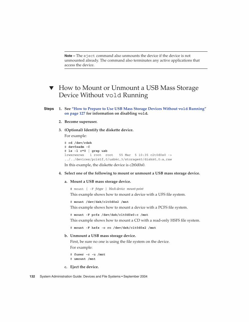
Note – The eject command also unmounts the device if the device is notunmounted already. The command also terminates any active applications thataccess the device.
� How to Mount or Unmount a USB Mass StorageDevice Without vold Running
1. See “How to Prepare to Use USB Mass Storage Devices Without vold Running”on page 127 for information on disabling vold.
2. Become superuser.
3. (Optional) Identify the diskette device.
For example:
# cd /dev/rdsk# devfsadm -C# ls -l c*0 | grep usblrwxrwxrwx 1 root root 55 Mar 5 10:35 c2t0d0s0 ->
../../devices/pci@1f,0/usb@c,3/storage@3/disk@0,0:a,raw
In this example, the diskette device is c2t0d0s0.
4. Select one of the following to mount or unmount a USB mass storage device.
a. Mount a USB mass storage device.
# mount [ -F fstype ] block-device mount-point
This example shows how to mount a device with a UFS file system.
# mount /dev/dsk/c1t0d0s2 /mnt
This example shows how to mount a device with a PCFS file system.
# mount -F pcfs /dev/dsk/c1t0d0s0:c /mnt
This example shows how to mount a CD with a read-only HSFS file system.
# mount -F hsfs -o ro /dev/dsk/c1t0d0s2 /mnt
b. Unmount a USB mass storage device.
First, be sure no one is using the file system on the device.
For example:
# fuser -c -u /mnt
# umount /mnt
c. Eject the device.
Steps
132 System Administration Guide: Devices and File Systems • September 2004

# eject /dev/[r]dsk/cntndnsn
For example:
# eject /dev/rdsk/c1t0d0s2
Disabling Specific USB DriversYou can disable specific types of USB devices by disabling their client driver. Forexample, USB printers can be disabled by disabling the usbprn driver that directsthem. Disabling usbprn does not affect other kinds of devices, such as USB storagedevices.
Be careful that device types are disabled on both frameworks. You cannot disabledevice types on one framework only. The following table identifies some USB devicetypes and their corresponding drivers.
Device Type Driver to Disable
audio usb_ac and usb_as
HID (usually keyboard and mouse hid
storage scsa2usb
printer usbprn
serial usbser_edge
If you disable a driver for a USB device that is still connected to the system, you willsee a console message similar to the following:
usba10: WARNING: usba: no driver found for device name
� How to Disable Specific USB Drivers
1. Become superuser.
2. Record the driver aliases that you are about to remove.
# cp /etc/driver_aliases /etc/driver_aliases.orig
3. Identify the specific USB driver alias name.
For example:
# grep usbprn /etc/driver_aliasesusbprn "usbif,class7.1.1"
usbprn "usbif,class7.1.2"
Steps
Chapter 8 • Using USB Devices (Tasks) 133

4. Remove the driver alias entry.
For example:
# update_drv -d -i ’"usbif,class7.1.1"’ usbprn
# update_drv -d -i ’"usbif,class7.1.2"’ usbprn
5. Reboot the system.
# init 6
� How to Remove Unused USB Device LinksUse this procedure if a USB device is removed while the system is powered off. It ispossible that removing the USB device while the system is powered off will leavedevice links for devices that do not exist.
1. Become superuser.
2. Close all applications that might be accessing the device.
3. Remove the unused links for a specific USB class.
For example:
# devfsadm -C -c audio
Or, just remove the dangling links:
# devfsadm -C
Hot-Plugging USB Devices (Task Map)
Task Description For Instructions
Add a USB mass storagedevice
Add a USB mass storagedevice with vold running.
“How to Add a USB MassStorage Device With voldRunning” on page 135
Add a USB mass storagedevice without vold running.
“How to Add a USB MassStorage Device Without voldRunning” on page 136
Steps
134 System Administration Guide: Devices and File Systems • September 2004
Task Description For Instructions
Remove a USB mass storagedevice
Remove a USB mass storagedevice with vold running.
“How to Remove a USB MassStorage Device With voldRunning” on page 136
Remove a USB mass storagedevice without vold running.
“How to Remove a USB MassStorage Device Without voldRunning” on page 137
Add a USB camera Add a USB camera to accessdigital images.
“How to Add a USB Camera”on page 137
Hot-plugging a device means the device is added or removed without shutting downthe operating system or powering off the system. All USB devices are hot-pluggable.
When you hot-plug a USB device, the device is immediately seen in the system’sdevice hierarchy, as displayed in the prtconf command output. When you remove aUSB device, the device is removed from the system’s device hierarchy, unless thedevice is in use.
If the USB device is in use when it is removed, the hot-plug behavior is a littledifferent. If a device is in use when it is unplugged, the device node remains, but thedriver controlling this device stops all activity on the device. Any new I/O activityissued to this device is returned with an error.
In this situation, the system prompts you to plug in the original device. If the device isno longer available, stop the applications. After a few seconds, the port will becomeavailable again.
Note – Data integrity might be impaired if you remove an active or open device.Always close the device before removing, except the console keyboard and mouse,which can be moved while active.
� How to Add a USB Mass Storage Device Withvold RunningThis procedure describes how to add a USB device with vold running.
1. Connect the USB mass storage device.
2. Instruct vold to scan for new devices.
# touch /etc/vold.conf
3. Restart vold.
Steps
Chapter 8 • Using USB Devices (Tasks) 135

# pkill -HUP vold
4. Verify that the device has been added.
$ ls device-alias
For more information on volume management device names, see Chapter 1.
� How to Add a USB Mass Storage Device Withoutvold RunningThis procedure describes how to add a USB device without vold running.
1. If needed, see “How to Prepare to Use USB Mass Storage Devices Without voldRunning” on page 127 for information on disabling vold.
2. Connect the USB mass storage device.
3. Verify that the USB device has been added.
Locate the USB disk device links, which may be among device links of non-USBstorage devices, as follows:
$ cd /dev/rdsk$ ls -l c*0 | grep usblrwxrwxrwx 1 root root 67 Apr 30 15:12 c1t0d0s0 ->
../../devices/pci@1f,0/pci@5/pci@0/usb@8,2/storage@1/disk@0,0:a,raw
� How to Remove a USB Mass Storage Device Withvold RunningThe following procedure uses a Zip drive as an example of removing a USB devicewith vold running.
1. Stop any active applications that are using the device.
2. Unmount the device.
For example:
$ volrmmount -e zip0
3. Eject the device.
For example:
$ eject zip0
4. Become superuser and stop vold.
Steps
Steps
136 System Administration Guide: Devices and File Systems • September 2004
# /etc/init.d/volmgt stop
5. Remove the USB mass storage device.
6. Start vold.
# /etc/init.d/volmgt start
� How to Remove a USB Mass Storage DeviceWithout vold RunningThis procedure describes how to remove a USB device without vold running.
1. If needed, see “How to Prepare to Use USB Mass Storage Devices Without voldRunning” on page 127 for information on disabling vold.
2. Become superuser.
3. Stop any active applications that are using the device.
4. Remove the USB device.
a. Unmount the device.
For example:
# umount /mnt
b. Remove the device.
� How to Add a USB CameraUse this procedure to add a USB camera.
1. Become superuser.
2. Plug in and turn on the USB camera.
The system creates a logical device for the camera. After the camera is plugged in,output is written to the /var/adm/messages file to acknowledge the device’sconnection. The camera is seen as a storage device to the system.
3. Examine the output that is written to the /var/adm/messages file.
Examining this output enables you to determine which logical device was createdso that you can then use that device to access your images. The output will looksimilar to the following:
# more /var/adm/messagesJul 15 09:53:35 buffy usba: [ID 349649 kern.info] OLYMPUS, C-3040ZOOM,
Steps
Steps
Chapter 8 • Using USB Devices (Tasks) 137

000153719068Jul 15 09:53:35 buffy genunix: [ID 936769 kern.info] scsa2usb1 is/pci@0,0/pci925,1234@7,2/storage@2Jul 15 09:53:36 buffy scsi: [ID 193665 kern.info] sd3 at scsa2usb1:
target 0 lun 0
Match the device with a mountable /dev/dsk link entry, by doing the following:
# ls -l /dev/dsk/c*0 | grep /pci@0,0/pci925,1234@7,2/storage@2lrwxrwxrwx 1 root root 58 Jul 15 2002 c3t0d0p0 ->
../../devices/pci@0,0/pci925,1234@7,2/storage@2/disk@0,0:a
4. Mount the USB camera file system.
The camera’s file system is most likely a PCFS file system. In order to mount thefile system on the device created, the slice that represents the disk must bespecified. The slice is normally s0 for a SPARC system, and p0 for an x86 system.
For example, to mount the file system on an x86 system, execute the followingcommand:
# mount -F pcfs /dev/dsk/c3t0d0p0:c /mnt
To mount the file system on a SPARC system, execute the following command:
# mount -F pcfs /dev/dsk/c3t0d0s0:c /mnt
For information on mounting file systems, see Chapter 17.
For information on mounting different PCFS file systems, see mount_pcfs(1M).
5. Verify that the image files are available.
For example:
# ls /mnt/DCIM/100OLYMP/P7220001.JPG* P7220003.JPG* P7220005.JPG*
P7220002.JPG* P7220004.JPG* P7220006.JPG*
6. View and manipulate the image files created by the USB camera.
# /usr/dt/bin/sdtimage P7220001.JPG &
7. Unmount the file system before disconnecting the camera.
For example:
# umount /mnt
8. Turn off and disconnect the camera.
138 System Administration Guide: Devices and File Systems • September 2004
Using USB Audio Devices (Task Map)
Task Description For Instructions
Add USB audio devices Add a USB microphone andspeakers.
“How to Add USB AudioDevices” on page 141
Identify your system’sprimary audio device
Identify which audio device isyour primary audio device.
“How to Identify YourSystem’s Primary AudioDevice” on page 141
Change the primary USBaudio device
You might want to make oneparticular audio device theprimary audio device if youremove or change your USBaudio devices.
“How to Change the PrimaryUSB Audio Device” on page142
Remove unused USB devicelinks
If you remove a USB audiodevice while the system ispowered off, the /dev/audiodevice might be pointing to a/dev/sound/* device thatdoesn’t exist.
“How to Remove UnusedUSB Device Links” on page134
Solve USB audio problems Use this section if no soundcomes from the USB speakers.
“Solving USB AudioProblems” on page 142
Using USB Audio DevicesThis Solaris release provides USB audio support that is implemented by a pair ofcooperating drivers, usb_ac and usb_as. The audio control driver, usb_ac, is aUSBA (Solaris USB Architecture) compliant client driver that provides the controllinginterface to user applications. The audio streaming driver, usb_as, is provided toprocess audio data messages during play and record. It sets sample frequency andprecision, and encodes requests from the usb_ac driver. Both drivers comply to theUSB audio class 1.0 specification.
Some audio devices can set volume under software control. A STREAMS module,usb_ah, is pushed on top of the HID driver for managing this function.
Solaris supports USB audio devices that are play-only, record-only, or record and play.Hot-plugging of USB audio devices is supported.
� USB audio devices are supported on SPARC Ultra and x86 platforms that have USBconnectors.
Chapter 8 • Using USB Devices (Tasks) 139
� USB audio devices that are supported in the Solaris 8 10/01, Solaris 8 2/02, orSolaris 9 releases must support a fixed 44100 or 48000 Hz sampling frequency toplay or record.
� For fully supported audio data format information, see usb_ac(7D).
The primary audio device is /dev/audio. You can verify that /dev/audio ispointing to USB audio by using the following command:
% mixerctlDevice /dev/audioctl:Name = USB AudioVersion = 1.0Config = external
Audio mixer for /dev/audioctl is enabled
After you connect your USB audio devices, you access them with the audioplay andaudiorecord command through the /dev/sound/N device links.
Note that the /dev/audio and /dev/sound/N devices can refer to speakers,microphones, or combo devices. If you refer to the incorrect device type, the commandwill fail. For example, the audioplay command will fail if you try to use it with amicrophone.
You can select a specific default audio device for most Sun audio applications, such asaudioplay and audiorecord, by setting the AUDIODEV shell variable or byspecifying the -d option for these commands. However, setting AUDIODEV does notwork for third-party applications that have /dev/audio hardcoded as the audio file.
When you plug in a USB audio device, it automatically becomes the primary audiodevice, /dev/audio, unless /dev/audio is in use. For instructions on changing/dev/audio from onboard audio to USB audio and vice versa, refer to “How toChange the Primary USB Audio Device” on page 142, and usb_ac(7D).
Hot-Plugging Multiple USB Audio DevicesIf a USB audio device is plugged into a system, it becomes the primary audio device,/dev/audio. It remains the primary audio device even after the system is rebooted. Ifadditional USB audio devices are plugged in, the last one becomes the primary audiodevice.
For additional information on troubleshooting USB audio device problems, seeusb_ac(7D).
140 System Administration Guide: Devices and File Systems • September 2004
� How to Add USB Audio DevicesUse the following procedure to add USB audio devices.
1. Plug in the USB speaker.
The primary audio device, /dev/audio, points to the USB speaker.
% ls -l /dev/audio
lrwxrwxrwx 1 root root 10 Feb 13 08:46 /dev/audio -> usb/audio0
2. (Optional) Remove the speaker. Then plug it back in.
If you remove the speaker, the /dev/audio device reverts back to onboard audio.
% ls -l /dev/audio
lrwxrwxrwx 1 root root 7 Feb 13 08:47 /dev/audio -> sound/0
3. Add a USB microphone.
% ls -l /dev/audio
lrwxrwxrwx 1 root root 10 Feb 13 08:54 /dev/audio -> usb/audio1
� How to Identify Your System’s Primary AudioDeviceThis procedure assumes that you have already connected the USB audio devices.
� Examine your system’s new audio links.
For example:
% ls -lt /dev/audio*lrwxrwxrwx 1 root root 7 Jul 23 15:46 /dev/audio -> usb/audio0lrwxrwxrwx 1 root root 10 Jul 23 15:46 /dev/audioctl ->usb/audioctl0/% ls -lt /dev/sound/*lrwxrwxrwx 1 root root 74 Jul 23 15:46 /dev/sound/1 ->../../devices/pci@1f,4000/usb@5/hub@1/device@3/sound-control@0:sound,a...lrwxrwxrwx 1 root root 77 Jul 23 15:46 /dev/sound/1ctl ->../../devices/pci@1f,4000/usb@5/hub@1/device@3/sound-control@0:sound,a...lrwxrwxrwx 1 root other 66 Jul 23 14:21 /dev/sound/0 ->../../devices/pci@1f,4000/ebus@1/SUNW,CS4231@14,200000:sound,audiolrwxrwxrwx 1 root other 69 Jul 23 14:21 /dev/sound/0ctl ->../../devices/pci@1f,4000/ebus@1/SUNW,CS4231@14,200000:sound,audioctl
%
Notice that the primary audio device, /dev/audio, is pointing to the newlyplugged in USB audio device, /dev/usb/audio0.
You can also examine your system’s USB audio devices with the prtconfcommand and look for the USB device information.
Steps
Step
Chapter 8 • Using USB Devices (Tasks) 141

% prtconf...usb, instance #0
hub, instance #0mouse, instance #0keyboard, instance #1device, instance #0
sound-control, instance #0sound, instance #0input, instance #0
.
.
.
How to Change the Primary USB Audio Device� If you want the onboard audio device to become the primary audio device, remove
the USB audio devices. The /dev/audio link will then point to the/dev/sound/0 entry. If the /dev/sound/0 entry is not the primary audio device,then either shutdown the system and use the boot -r command, or run thedevfsadm -i command as root.
� If you want the USB audio device to become primary audio device, just plug it inand check the links.
Troubleshooting USB Audio Device ProblemsThis section describes how to troubleshoot USB audio device problems.
Solving USB Audio ProblemsSometimes USB speakers do not produce any sound even though the driver isattached and the volume is set to high. Hot-plugging the device might not change thisbehavior.
The workaround is to power cycle the USB speakers.
Key Points of Audio Device Ownership
Keep the following key points of audio device ownership in mind when working withaudio devices.
� When you plug in a USB audio device and you are logged in on the console, theconsole is the owner of the /dev/* entries. This situation means you can use theaudio device as long as you are logged into the console.
142 System Administration Guide: Devices and File Systems • September 2004

� If you are not logged into the console when you plug in a USB audio device, rootbecomes the owner of the device. However, if you log into the console and attemptto access the USB audio device, device ownership changes to the console. For moreinformation, see logindevperm(4).
� When you remotely login with the rlogin command and attempt to access theUSB audio device, the ownership does not change. This means that, for example,unauthorized users cannot listen to conversations over a microphone owned bysomeone else.
Hot-Plugging USB Devices With thecfgadm Command (Task Map)
Task Description For Instructions
Display USB bus information Display information aboutUSB devices and buses.
“How to Display USB BusInformation (cfgadm)”on page 145
Unconfigure a USB device Logically unconfigure a USBdevice that is still physicallyconnected to the system.
“How to Unconfigure a USBDevice” on page 146
Configure a USB device Configure a USB device thatwas previously unconfigured.
“How to Configure a USBDevice” on page 146
Logically disconnect a USBdevice
You can logically disconnect aUSB device if you are notphysically near the system.
“How to Logically Disconnecta USB Device” on page 146
Logically connect a USBdevice
Logically connect a USBdevice that was previouslylogically disconnected orunconfigured.
“How to Logically Connect aUSB Device” on page 147
Disconnect a USB devicesubtree
Disconnect a USB devicesubtree, which is the hierarchy(or tree) of devices below ahub.
“How to Logically Disconnecta USB Device Subtree”on page 147
Reset a USB device Reset a USB device tologically remove and recreatethe device.
“How to Reset a USB Device”on page 148
Chapter 8 • Using USB Devices (Tasks) 143

Task Description For Instructions
Change the defaultconfiguration of amulti-configuration USBdevice
Change the defaultconfiguration of amulti-configuration USBdevice.
“How to Change the DefaultConfiguration of aMulti-Configuration USBDevice” on page 148
Hot-Plugging USB Devices With the cfgadmCommandYou can add and remove a USB device from a running system without using thecfgadm command. However, a USB device can also be logically hot-plugged withoutphysically removing the device. This scenario is convenient when you are workingremotely and you need to disable or reset a non-functioning USB device. The cfgadmcommand also provides a way to display the USB device tree including manufacturerand product information.
The cfgadm command displays information about attachment points, which arelocations in the system where dynamic reconfiguration operations can occur. Anattachment point consists of:
� An occupant, which represents a hardware resource, such as a USB device, thatmight be configured into the system, and
� A receptacle, which is the location that accepts the occupant, such as a USB port.
Attachment points are represented by logical and physical attachment point IDs(Ap_Ids). The physical Ap_Id is the physical pathname of the attachment point. Thelogical Ap_Id is a user-friendly alternative for the physical Ap_Id. For moreinformation on Ap_Ids, see cfgadm_usb(1M).
The cfgadm command provides the following USB device status information.
Receptacle State Description
empty/unconfigured The device is not physically connected.
disconnected/unconfigured The device is logically disconnected andunavailable, even though the device could stillbe physically connected.
connected/unconfigured The device is logically connected, butunavailable. The device is visible in prtconfoutput.
connected/configured The device is connected and available.
144 System Administration Guide: Devices and File Systems • September 2004

The following sections describe how to hot-plug a USB device through the softwarewith the cfgadm command. All of the sample USB device information in thesesections has been truncated to focus on relevant information.
How to Display USB Bus Information (cfgadm)Use the cfgadm command to display USB bus information. For example:
% cfgadmAp_Id Type Receptacle Occupant Conditionusb0/4.5 usb-hub connected configured okusb0/4.5.1 usb-device connected configured okusb0/4.5.2 usb-printer connected configured okusb0/4.5.3 usb-mouse connected configured okusb0/4.5.4 usb-device connected configured okusb0/4.5.5 usb-storage connected configured okusb0/4.5.6 usb-communi connected configured okusb0/4.5.7 unknown empty unconfigured okusb0/4.6 usb-storage connected configured ok
usb0/4.7 usb-storage connected configured ok
In the preceding example, usb0/4.5.1 identifies a device connected to port 1 of thesecond-level external hub, which is connected to port 5 of first-level external hub,which is connected to the first USB controller’s root hub, port 4.
Use the following cfgadm command to display specific USB device information. Forexample:
% cfgadm -l -s "cols=ap_id:info"Ap_Id Informationusb0/4.5.1 Mfg: Inside Out Networks Product: Edgeport/421 NConfigs: 1Config: 0 : ...usb0/4.5.2 Mfg: <undef> Product: <undef> NConfigs: 1 Config: 0 ...usb0/4.5.3 Mfg: Mitsumi Product: Apple USB Mouse NConfigs: 1 Config: 0 ...usb0/4.5.4 Mfg: NMB Product: NMB USB KB/PS2 M NConfigs: 1 Config: 0usb0/4.5.5 Mfg: Hagiwara Sys-Com Product: SmartMedia R/W NConfigs: 1Config: 0 : ...usb0/4.5.6 Mfg: 3Com Inc. Product: U.S.Robotics 56000 Voice USB ModemNConfigs: 2 ...usb0/4.5.7usb0/4.6 Mfg: Iomega Product: USB Zip 250 NConfigs: 1 Config: 0: Defaultusb0/4.7 Mfg: Iomega Product: USB Zip 100 NConfigs: 1 Config: 0
: Default
For examples of using the prtconf command to display USB configurationinformation, see “How to Display USB Device Information (prtconf)” on page 128.
Chapter 8 • Using USB Devices (Tasks) 145

� How to Unconfigure a USB DeviceYou can unconfigure a USB device that is still physically connected to the system, buta driver will never attach to it. Note that a USB device remains in the prtconf outputeven after that device is unconfigured.
1. Become superuser.
2. Unconfigure the USB device.
# cfgadm -c unconfigure usb0/4.7Unconfigure the device: /devices/pci@8,700000/usb@5,3/hub@4:4.7This operation will suspend activity on the USB device
Continue (yes/no)? y
3. Verify that the device is unconfigured.
# cfgadmAp_Id Type Receptacle Occupant Conditionusb0/4.5 usb-hub connected configured okusb0/4.5.1 usb-device connected configured okusb0/4.5.2 usb-printer connected configured okusb0/4.5.3 usb-mouse connected configured okusb0/4.5.4 usb-device connected configured okusb0/4.5.5 usb-storage connected configured okusb0/4.5.6 usb-communi connected configured okusb0/4.5.7 unknown empty unconfigured okusb0/4.6 usb-storage connected configured ok
usb0/4.7 usb-storage connected unconfigured ok
� How to Configure a USB Device
1. Become superuser.
2. Configure a USB device.
# cfgadm -c configure usb0/4.7
3. Verify that the USB device is configured.
# cfgadm usb0/4.7Ap_Id Type Receptacle Occupant Condition
usb0/4.7 usb-storage connected configured ok
� How to Logically Disconnect a USB DeviceIf you want to remove a USB device from the system and the prtconf output, butyou are not physically near the system, just logically disconnect the USB device. Thedevice is still physically connected, but it is logically disconnected, unusable, and notvisible to the system.
Steps
Steps
146 System Administration Guide: Devices and File Systems • September 2004

1. Become superuser.
2. Disconnect a USB device.
# cfgadm -c disconnect -y usb0/4.7
3. Verify that the device is disconnected.
# cfgadm usb0/4.7Ap_Id Type Receptacle Occupant Condition
usb0/4.7 unknown disconnected unconfigured ok
� How to Logically Connect a USB DeviceUse this procedure to logically connect a USB device that was previously logicallydisconnected or unconfigured.
1. Become superuser.
2. Connect a USB device.
# cfgadm -c configure usb0/4.7
3. Verify that the device is connected.
# cfgadm usb0/4.7Ap_Id Type Receptacle Occupant Condition
usb0/4.7 usb-storage connected configured ok
The device is now available and visible to the system.
� How to Logically Disconnect a USB Device SubtreeUse this procedure to disconnect a USB device subtree, which is the hierarchy (or tree)of devices below a hub.
1. Become superuser.
2. Remove a USB device subtree.
# cfgadm -c disconnect -y usb0/4
3. Verify that the USB device subtree is disconnected.
# cfgadm usb0/4Ap_Id Type Receptacle Occupant Condition
usb0/4 unknown disconnected unconfigured ok
Steps
Steps
Steps
Chapter 8 • Using USB Devices (Tasks) 147
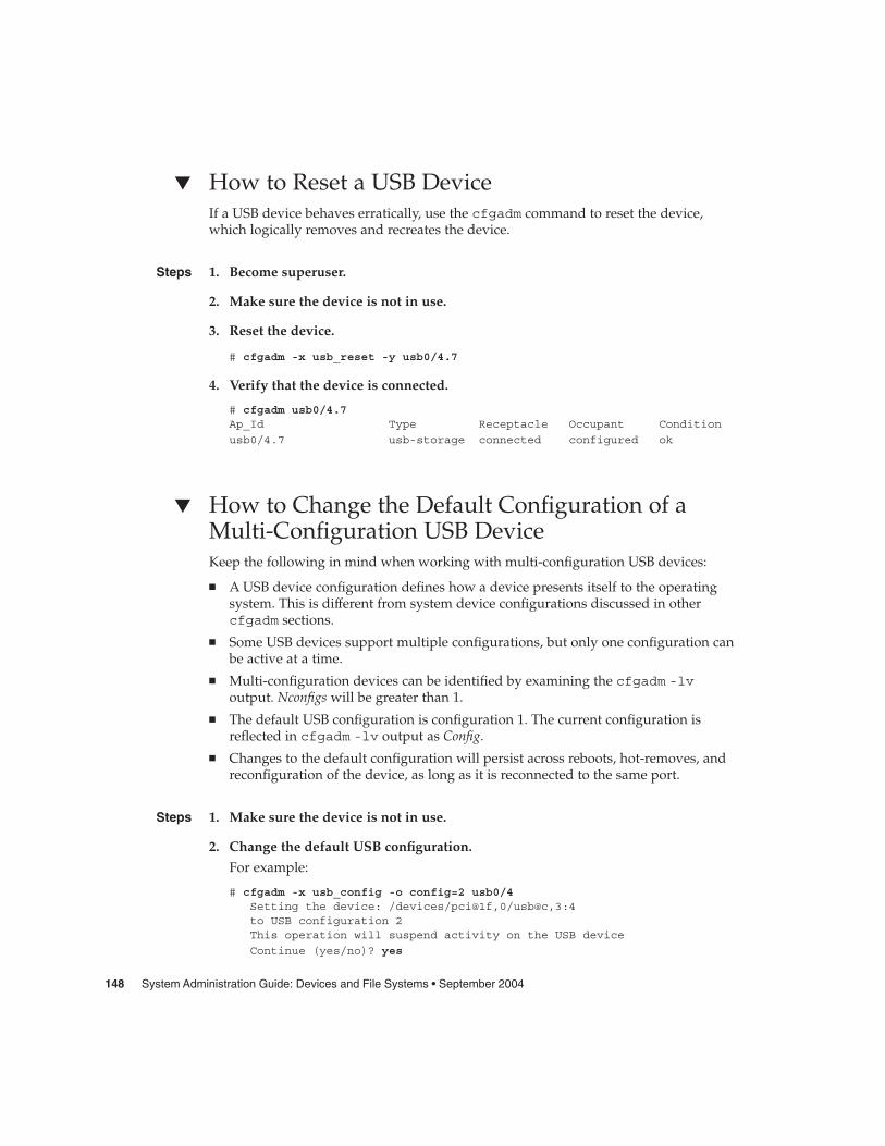
� How to Reset a USB DeviceIf a USB device behaves erratically, use the cfgadm command to reset the device,which logically removes and recreates the device.
1. Become superuser.
2. Make sure the device is not in use.
3. Reset the device.
# cfgadm -x usb_reset -y usb0/4.7
4. Verify that the device is connected.
# cfgadm usb0/4.7Ap_Id Type Receptacle Occupant Condition
usb0/4.7 usb-storage connected configured ok
� How to Change the Default Configuration of aMulti-Configuration USB DeviceKeep the following in mind when working with multi-configuration USB devices:
� A USB device configuration defines how a device presents itself to the operatingsystem. This is different from system device configurations discussed in othercfgadm sections.
� Some USB devices support multiple configurations, but only one configuration canbe active at a time.
� Multi-configuration devices can be identified by examining the cfgadm -lvoutput. Nconfigs will be greater than 1.
� The default USB configuration is configuration 1. The current configuration isreflected in cfgadm -lv output as Config.
� Changes to the default configuration will persist across reboots, hot-removes, andreconfiguration of the device, as long as it is reconnected to the same port.
1. Make sure the device is not in use.
2. Change the default USB configuration.
For example:
# cfgadm -x usb_config -o config=2 usb0/4Setting the device: /devices/pci@1f,0/usb@c,3:4to USB configuration 2This operation will suspend activity on the USB device
Continue (yes/no)? yes
Steps
Steps
148 System Administration Guide: Devices and File Systems • September 2004

3. Verify the device change.
For example:
# cfgadm -lv usb0/4Ap_Id Receptacle Occupant Condition Information When Type
Busy Phys_Idusb0/4 connected unconfigured ok Mfg: Sun 2000Product: USB-B0B0 aka RobotechWith 6 EPPS High Clk Mode NConfigs: 7 Config: 2 : EVAL Board Setupunavailable
usb-device n /devices/pci@1f,0/usb@c,3:4
Config now shows 2.
Chapter 8 • Using USB Devices (Tasks) 149

150 System Administration Guide: Devices and File Systems • September 2004

CHAPTER 9
Accessing Devices (Overview)
This chapter provides information about how to access the devices on a system.
This is a list of the overview information in this chapter.
� “Accessing Devices” on page 151� “Logical Disk Device Names” on page 153� “Logical Tape Device Names” on page 156� “Logical Removable Media Device Names” on page 157
For overview information about configuring devices, see Chapter 5.
Accessing DevicesYou need to know how to specify device names when using commands to managedisks, file systems, and other devices. In most cases, you can use logical device namesto represent devices that are connected to the system. Both logical and physical devicenames are represented on the system by logical and physical device files.
How Device Information Is CreatedWhen a system is booted for the first time, a device hierarchy is created to represent allthe devices connected to the system. The kernel uses the device hierarchy informationto associate drivers with their appropriate devices, and provides a set of pointers tothe drivers that perform specific operations. For more information on device hierarchy,see OpenBoot 3.x Command Reference Manual.
151

How Devices Are ManagedThe devfsadm command manages the special device files in the /dev and /devicesdirectories. By default, the devfsadm command attempts to load every driver in thesystem and attach to all possible device instances. Then, devfsadm creates the devicefiles in the /devices directory and the logical links in the /dev directory. In additionto managing the /dev and /devices directories, the devfsadm command alsomaintains the path_to_inst(4) instance database.
Both reconfiguration boot processing and updating the /dev and /devicesdirectories in response to dynamic reconfiguration events is handled by devfsadmd,the daemon version of the devfsadm command. This daemon is started from the/etc/rc* scripts when a system is booted.
Since the devfsadmd daemon automatically detects device configuration changesgenerated by any reconfiguration event, there is no need to run this commandinteractively.
For more information, see devfsadm(1M).
Device Naming ConventionsDevices are referenced in three ways in the Solaris environment.
� Physical device name – Represents the full device pathname in the deviceinformation hierarchy. Physical device names are displayed by using the followingcommands:
� dmesg� format� sysdef� prtconf
Physical device files are found in the /devices directory.
� Instance name – Represents the kernel’s abbreviation name for every possibledevice on the system. For example, sd0 and sd1 represent the instance names oftwo disk devices. Instance names are mapped in the /etc/path_to_inst fileand are displayed by using the following commands:
� dmesg� sysdef� prtconf
� Logical device name – Used with most file system commands to refer to devices.For a list of file commands that use logical device names, see Table 9–1. Logicaldevice files in the /dev directory are symbolically linked to physical device files inthe /devices directory.
152 System Administration Guide: Devices and File Systems • September 2004

Logical Disk Device NamesLogical device names are used to access disk devices when you:
� Add a new disk to the system� Move a disk from one system to another system� Access or mount a file system residing on a local disk� Back up a local file system
Many administration commands take arguments that refer to a disk slice or filesystem.
Refer to a disk device by specifying the subdirectory to which it is symbolically linked,either /dev/dsk or /dev/rdsk, followed by a string identifying the particularcontroller, disk, and slice.
/dev/[r]dsk/cwtxdysz
Logical controller number
Physical bus target number
Drive number
Raw disk device subdirectory
Devices directory
Slice number (0 to 7) or fdisk partition number (0 to 4)
FIGURE 9–1 Logical Device Names
Specifying the Disk SubdirectoryDisk and file administration commands require the use of either a raw (or character)device interface, or a block device interface. The distinction is made by how data isread from the device.
Raw device interfaces transfer only small amounts of data at a time. Block deviceinterfaces include a buffer from which large blocks of data are read at once.
Different commands require different interfaces.
� When a command requires the raw device interface, specify the /dev/rdsksubdirectory. (The “r” in rdsk stands for “raw.”)
� When a command requires the block device interface, specify the /dev/dsksubdirectory.
Chapter 9 • Accessing Devices (Overview) 153

� When you are not sure whether a command requires use of /dev/dsk or/dev/rdsk, check the man page for that command.
The following table shows which interface is required for some commonly used diskand file system commands.
TABLE 9–1 Device Interface Type Required by Some Frequently Used Commands
Command Interface Type Example of Use
df(1M) Block df /dev/dsk/c0t3d0s6
fsck(1M) Raw fsck -p /dev/rdsk/c0t0d0s0
mount(1M) Block mount /dev/dsk/c1t0d0s7 /export/home
newfs(1M) Raw newfs /dev/rdsk/c0t0d1s1
prtvtoc(1M) Raw prtvtoc /dev/rdsk/c0t0d0s2
Specifying the SliceThe string that you use to identify a specific slice on a specific disk depends on thecontroller type, either direct or bus-oriented. The following table describes thedifferent types of direct or bus-oriented controllers on different platforms.
TABLE 9–2 Controller Types
Direct controllers Bus-Oriented Controllers
IDE (x86) SCSI (SPARC/x86)
FCAL (SPARC)
ATA (SPARC/x86)
The conventions for both types of controllers are explained in the followingsubsections.
Note – Controller numbers are assigned automatically at system initialization. Thenumbers are strictly logical and imply no direct mapping to physical controllers.
x86: Disks With Direct ControllersTo specify a slice on a disk with an IDE controller on an x86 based system, follow thenaming convention shown in the following figure.
154 System Administration Guide: Devices and File Systems • September 2004
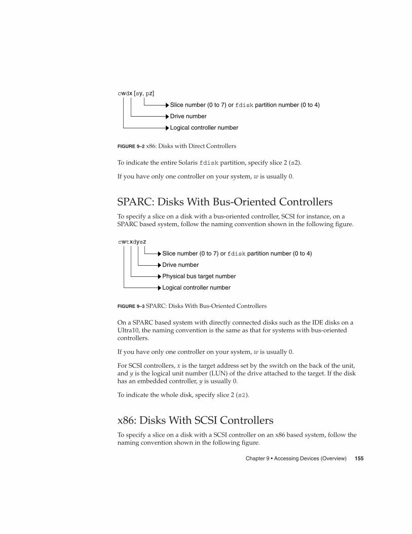
cwdx [sy, pz]
Slice number (0 to 7) or fdisk partition number (0 to 4)
Drive number
Logical controller number
FIGURE 9–2 x86: Disks with Direct Controllers
To indicate the entire Solaris fdisk partition, specify slice 2 (s2).
If you have only one controller on your system, w is usually 0.
SPARC: Disks With Bus-Oriented ControllersTo specify a slice on a disk with a bus-oriented controller, SCSI for instance, on aSPARC based system, follow the naming convention shown in the following figure.
cwtxdysz
Slice number (0 to 7) or fdisk partition number (0 to 4)
Drive number
Physical bus target number
Logical controller number
FIGURE 9–3 SPARC: Disks With Bus-Oriented Controllers
On a SPARC based system with directly connected disks such as the IDE disks on aUltra10, the naming convention is the same as that for systems with bus-orientedcontrollers.
If you have only one controller on your system, w is usually 0.
For SCSI controllers, x is the target address set by the switch on the back of the unit,and y is the logical unit number (LUN) of the drive attached to the target. If the diskhas an embedded controller, y is usually 0.
To indicate the whole disk, specify slice 2 (s2).
x86: Disks With SCSI ControllersTo specify a slice on a disk with a SCSI controller on an x86 based system, follow thenaming convention shown in the following figure.
Chapter 9 • Accessing Devices (Overview) 155

cvtwdx [sy, pz]
Slice number (0 to 7) or fdisk partition number (0 to 4)
Drive number
Physical bus target number
Logical controller number
FIGURE 9–4 x86: Disks with SCSI Controllers
If you have only one controller on your system, v is usually 0.
For SCSI controllers, w is the target address set by the switch on the back of the unit,and x is the logical unit number (LUN) of the drive attached to the target. If the diskhas an embedded controller, x is usually 0.
To indicate the entire Solaris fdisk partition, specify slice 2 (s2).
Logical Tape Device NamesLogical tape device files are found in the /dev/rmt/* directory as symbolic linksfrom the /devices directory.
/dev/rmt/xy
Drive number (0-n)
Raw magnetic tape device directory
Devices directory
Optional densityl lowm mediumh highu ultrac compressed
FIGURE 9–5 Logical Tape Device Names
The first tape device connected to the system is 0 (/dev/rmt/0). Tape density values(l, m, h, c, and u) are described in Chapter 28.
156 System Administration Guide: Devices and File Systems • September 2004
Logical Removable Media Device NamesSince removable media is managed by volume management (vold), the logical devicename is usually not used unless you want to mount the media manually.
The logical device name that represents the removable media devices on a system aredescribed in Chapter 2.
Chapter 9 • Accessing Devices (Overview) 157

158 System Administration Guide: Devices and File Systems • September 2004

CHAPTER 10
Managing Disks (Overview)
This chapter provides overview information about Solaris disk slices and introducesthe format utility.
This is a list of overview information in this chapter.
� “What’s New in Disk Management in the Solaris 9 Update Releases?” on page 159� “Where to Find Disk Management Tasks” on page 164� “Overview of Disk Management” on page 164� “Disk Terminology” on page 164� “About Disk Slices” on page 165� “The format Utility” on page 170� “About Disk Labels” on page 174� “Dividing a Disk Into Slices” on page 176
For instructions on how to add a disk to your system, see Chapter 12 or Chapter 13.
What’s New in Disk Management in theSolaris 9 Update Releases?This section describes new disk management features in this Solaris release.
SPARC: Multiterabyte Disk Support With EFI DiskLabelSolaris 9 4/03 – Provides support for disks that are larger than 1 terabyte on systemsthat run a 64-bit Solaris kernel.
159

You can download the EFI specification athttp://www.intel.com/technology/efi/main_specification.htm.
The EFI label provides support for physical disks and virtual disk volumes. Thisrelease also includes updated disk utilities for managing disks greater than 1 terabyte.The UFS file system is compatible with the EFI disk label, and you can create a UFSfile system greater than 1 terabyte. For information on creating a multiterabyte UFSfile system, see “SPARC: Support of Multiterabyte UFS File Systems” on page 243.
The unbundled Sun QFS file system is also available if you need to create file systemsgreater than 1 terabyte. For information on the Sun QFS file system, seehttp://docs.sun.com/db/doc/816-2542-10.
The Solaris Volume Manager software can also be used to manage disks greater than 1terabyte in this Solaris release. For information on using Solaris Volume Manager, seeSolaris Volume Manager Administration Guide.
The VTOC label is still available for disks less than 1 terabyte in size. If you are onlyusing disks smaller than 1 terabyte on your systems, managing disks will be the sameas in previous Solaris releases. In addition, you can use the format-e command tolabel a disk less than 1 terabyte with an EFI label. For more information, see Example11–6.
Comparison of the EFI Label and the VTOC LabelThe EFI disk label differs from the VTOC disk label in the following ways:
� Provides support for disks greater than 1 terabyte in size.� Provides usable slices 0–6, where slice 2 is just another slice.� Partitions (or slices) cannot overlap with the primary or backup label, nor with any
other partitions. The size of the EFI label is usually 34 sectors, so partitions start atsector 34. This feature means no partition can start at sector zero (0).
� No cylinder, head, or sector information is stored in the label. Sizes are reported inblocks.
� Information that was stored in the alternate cylinders area, the last two cylinders ofthe disk, is now stored in slice 8.
� If you use the format utility to change partition sizes, the unassigned partitiontag is assigned to partitions with sizes equal to zero. By default, the format utilityassigns the usr partition tag to any partition with a size greater than zero. You canuse the partition change menu to reassign partition tags after the partitions arechanged. However, you cannot change a partition with a non-zero size to theunassigned partition tag.
Restrictions of the EFI Disk LabelKeep the following restrictions in mind when determining whether to use disksgreater than 1 terabyte is appropriate for your environment:
160 System Administration Guide: Devices and File Systems • September 2004
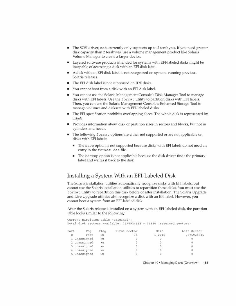
� The SCSI driver, ssd, currently only supports up to 2 terabytes. If you need greaterdisk capacity than 2 terabytes, use a volume management product like SolarisVolume Manager to create a larger device.
� Layered software products intended for systems with EFI-labeled disks might beincapable of accessing a disk with an EFI disk label.
� A disk with an EFI disk label is not recognized on systems running previousSolaris releases.
� The EFI disk label is not supported on IDE disks.� You cannot boot from a disk with an EFI disk label.� You cannot use the Solaris Management Console’s Disk Manager Tool to manage
disks with EFI labels. Use the format utility to partition disks with EFI labels.Then, you can use the Solaris Management Console’s Enhanced Storage Tool tomanage volumes and disksets with EFI-labeled disks.
� The EFI specification prohibits overlapping slices. The whole disk is represented bycxtydz.
� Provides information about disk or partition sizes in sectors and blocks, but not incylinders and heads.
� The following format options are either not supported or are not applicable ondisks with EFI labels:
� The save option is not supported because disks with EFI labels do not need anentry in the format.dat file.
� The backup option is not applicable because the disk driver finds the primarylabel and writes it back to the disk.
Installing a System With an EFI-Labeled DiskThe Solaris installation utilities automatically recognize disks with EFI labels, butcannot use the Solaris installation utilities to repartition these disks. You must use theformat utility to repartition this disk before or after installation. The Solaris Upgradeand Live Upgrade utilities also recognize a disk with an EFI label. However, youcannot boot a system from an EFI-labeled disk.
After the Solaris release is installed on a system with an EFI-labeled disk, the partitiontable looks similar to the following:
Current partition table (original):Total disk sectors available: 2576924638 + 16384 (reserved sectors)
Part Tag Flag First Sector Size Last Sector0 root wm 34 1.20TB 25769246361 unassigned wm 0 0 02 unassigned wm 0 0 03 unassigned wm 0 0 04 unassigned wm 0 0 05 unassigned wm 0 0 0
Chapter 10 • Managing Disks (Overview) 161

6 unassigned wm 0 0 0
8 reserved wm 2576924638 8.00MB 2576941021
Managing Disks With EFI Disks LabelsUse the following table to locate information on managing disks with EFI disk labels.
Task For More Information
If the system is already installed, connect thedisk to the system and perform areconfiguration boot.
“SPARC: Adding a System Disk or aSecondary Disk (Task Map)” on page 201
Repartition the disk with the format utility, ifnecessary.
“SPARC: How to Create Disk Slices and Labela Disk” on page 204
Create disk volumes, and if needed, create softpartitions with Solaris Volume Manager.
Chapter 2, “Storage Management Concepts,”in Solaris Volume Manager Administration Guide
Create UFS file systems for the new disk withthe newfs command.
“SPARC: How to Create a UFS File System”on page 209
Or, create a QFS file system. http://docs.sun.com/db/coll/20445.2
Cloning a Disk with an EFI LabelIn previous Solaris releases, slice 2 (s2) was used to represent the whole disk. Youcould use the dd command to clone or copy disks by using syntax similar to thefollowing:
dd if=/dev/rdsk/c0t0d0s2 of=/dev/rdsk/c0t2d0s2 bs=128k
Now, you must use a slightly different procedure to clone or copy disks larger than 1terabyte so that the UUID of cloned disks are unique. For example:
1. Use the dd command to clone the disk with an EFI label:
# dd if=/dev/rdsk/c0t0d0 of=/dev/rdsk/c0t2d0 bs=128k
2. Pipe the prtvtoc output of the disk to be copied to the fmthard command tocreate a new label for the cloned disk.
# prtvtoc /dev/rdsk/c0t0d0 | fmthard -s - /dev/rdsk/c0t2d0
Caution – If you do not create a new label for the cloned disk, other software productsmight corrupt data on EFI-labeled disks if they encounter duplicate UUIDs.
162 System Administration Guide: Devices and File Systems • September 2004
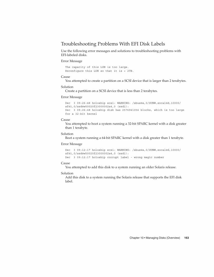
Troubleshooting Problems With EFI Disk LabelsUse the following error messages and solutions to troubleshooting problems withEFI-labeled disks.
Error Message
The capacity of this LUN is too large.
Reconfigure this LUN so that it is < 2TB.
CauseYou attempted to create a partition on a SCSI device that is larger than 2 terabytes.
SolutionCreate a partition on a SCSI device that is less than 2 terabytes.
Error Message
Dec 3 09:26:48 holoship scsi: WARNING: /sbus@a,0/SUNW,socal@d,10000/sf@1,0/ssd@w50020f23000002a4,0 (ssd1):Dec 3 09:26:48 holoship disk has 2576941056 blocks, which is too large
for a 32-bit kernel
CauseYou attempted to boot a system running a 32-bit SPARC kernel with a disk greaterthan 1 terabyte.
SolutionBoot a system running a 64-bit SPARC kernel with a disk greater than 1 terabyte.
Error Message
Dec 3 09:12:17 holoship scsi: WARNING: /sbus@a,0/SUNW,socal@d,10000/sf@1,0/ssd@w50020f23000002a4,0 (ssd1):
Dec 3 09:12:17 holoship corrupt label - wrong magic number
CauseYou attempted to add this disk to a system running an older Solaris release.
SolutionAdd this disk to a system running the Solaris release that supports the EFI disklabel.
Chapter 10 • Managing Disks (Overview) 163

Where to Find Disk Management TasksUse these references to find step-by-step instructions for managing disks.
Disk Management Task For More Information
Format a disk and examine a disk label Chapter 11
Add a new disk to a SPARC system Chapter 12
Add a new disk to an x86 system Chapter 13
Hot-Plug a SCSI or PCI disk Chapter 6
Overview of Disk ManagementThe management of disks in the Solaris environment usually involves setting up thesystem and running the Solaris installation program to create the appropriate diskslices and file systems and to install the operating system. Occasionally, you mightneed to use the format utility to add a new disk drive or replace a defective one.
Note – The Solaris operating system runs on two types of hardware, orplatforms—SPARC and x86. The Solaris operating system runs on both 64–bit and32–bit address spaces. The information in this document pertains to both platformsand address spaces unless called out in a special chapter, section, note, bullet, figure,table, example, or code example.
Disk TerminologyBefore you can effectively use the information in this section, you should be familiarwith basic disk architecture. In particular, you should be familiar with the followingterms:
164 System Administration Guide: Devices and File Systems • September 2004

Disk Term Description
Track A concentric ring on a disk that passes under a singlestationary disk head as the disk rotates.
Cylinder The set of tracks with the same nominal distance from theaxis about which the disk rotates.
Sector Section of each disk platter. A sector holds 512 bytes.
Block A data storage area on a disk. A disk block is 512 bytes.
Disk controller A chip and its associated circuitry that controls the diskdrive.
Disk label The first sector of a disk that contains disk geometry andpartition information.
Device driver A device driver is a kernel module that controls a hardwareor virtual device.
For additional information, see the product information from your disk’smanufacturer.
About Disk SlicesFiles stored on a disk are contained in file systems. Each file system on a disk isassigned to a slice, which is a group of sectors set aside for use by that file system.Each disk slice appears to the operating system (and to the system administrator) asthough it were a separate disk drive.
For information about file systems, see Chapter 15.
Note – Slices are sometimes referred to as partitions. This book uses slice but certaininterfaces, such as the format utility, refer to slices as partitions.
When setting up slices, remember these rules:
� Each disk slice holds only one file system.� No file system can span multiple slices.
Slices are set up slightly differently on SPARC and x86 platforms. The following tablesummarizes the differences.
Chapter 10 • Managing Disks (Overview) 165

TABLE 10–1 Slice Differences on Platforms
SPARC Platform x86 Platform
Whole disk is devoted to Solaris environment. Disk is divided into fdisk partitions, onefdisk partition per operating system.
VTOC – Disk is divided into 8 slices,numbered 0–7.
EFI – Disk is divided into 7 slices, numbered0–6.
VTOC – The Solaris fdisk partition isdivided into 10 slices, numbered 0–9.
Solaris Volume Manager, previously Solstice DiskSuite™, has a partitioning feature,soft partitioning, that enables more than eight partitions per disk.
For general information about Solaris Volume Manager, see Chapter 2, “StorageManagement Concepts,” in Solaris Volume Manager Administration Guide. Forinformation on soft partitioning, see Chapter 12, “Soft Partitions (Overview),” inSolaris Volume Manager Administration Guide.
SPARC: Disk SlicesThe following table describes the slices on a SPARC based system.
TABLE 10–2 SPARC: Customary Disk Slices
Slice File SystemUsually Found on Client orServer Systems? Comments
0 root (/) Both Holds files and directories that makeup the operating system.
EFI – You cannot boot from a diskwith an EFI label.
1 swap Both Provides virtual memory, or swapspace.
2 — Both VTOC – Refers to the entire disk, byconvention. The size of this sliceshould not be changed.
EFI – Optional slice to be definedbased on your site’s needs.
166 System Administration Guide: Devices and File Systems • September 2004
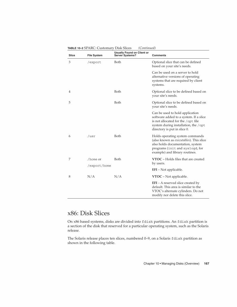
TABLE 10–2 SPARC: Customary Disk Slices (Continued)
Slice File SystemUsually Found on Client orServer Systems? Comments
3 /export Both Optional slice that can be definedbased on your site’s needs.
Can be used on a server to holdalternative versions of operatingsystems that are required by clientsystems.
4 Both Optional slice to be defined based onyour site’s needs.
5 Both Optional slice to be defined based onyour site’s needs.
Can be used to hold applicationsoftware added to a system. If a sliceis not allocated for the /opt filesystem during installation, the /optdirectory is put in slice 0.
6 /usr Both Holds operating system commands(also known as executables). This slicealso holds documentation, systemprograms (init and syslogd, forexample) and library routines.
7 /home or
/export/home
Both VTOC – Holds files that are createdby users.
EFI – Not applicable.
8 N/A N/A VTOC – Not applicable.
EFI – A reserved slice created bydefault. This area is similar to theVTOC’s alternate cylinders. Do notmodify nor delete this slice.
x86: Disk SlicesOn x86 based systems, disks are divided into fdisk partitions. An fdisk partition isa section of the disk that reserved for a particular operating system, such as the Solarisrelease.
The Solaris release places ten slices, numbered 0–9, on a Solaris fdisk partition asshown in the following table.
Chapter 10 • Managing Disks (Overview) 167

TABLE 10–3 x86: Customary Disk Slices
Slice File SystemUsually Found on Client orServer Systems? Purpose
0 root (/) Both Holds the files and directories thatmake up the operating system.
1 swap Both Provides virtual memory, or swapspace.
2 — Both Refers to the entire disk, byconvention. The size of this sliceshould not be changed.
3 /export Both Optional slice to be defined basedon your site’s needs.
Can be used on a server to holdalternative versions of operatingsystems that are required by clientsystems.
4 Optional slice to be defined basedon your site’s needs.
5 Both Optional slice to be defined basedon your site’s needs.
Can be used to hold applicationsoftware added to a system. If aslice is not allocated for the /optfile system during installation, the/opt directory is put in slice 0.
6 /usr Both Holds operating systemcommands (also known asexecutables). This slice also holdsdocumentation, system programs(init and syslogd, for example)and library routines.
7 /home or/export/home
Both Holds files that are created byusers.
8 — Both Contains information necessary forto boot the Solaris environmentfrom the hard disk. The sliceresides at the beginning of theSolaris fdisk partition (althoughthe slice number itself does notindicate this fact), and is known asthe boot slice.
168 System Administration Guide: Devices and File Systems • September 2004

TABLE 10–3 x86: Customary Disk Slices (Continued)
Slice File SystemUsually Found on Client orServer Systems? Purpose
9 — Both Provides an area that is reservedfor alternate disk blocks. Slice 9 isknown as the alternate sector slice.
Using Raw Data SlicesThe SunOS operating system stores the disk label in block 0 of each disk. So,third-party database applications that create raw data slices must not start at block 0,or the disk label will be overwritten and the data on the disk will be inaccessible.
Do not use the following areas of the disk for raw data slices, which are sometimescreated by third-party database applications:
� Block 0 where the disk label is stored� Slice 2, which represents the entire disk with a VTOC label
Slice Arrangements on Multiple DisksAlthough a single large disk can hold all slices and their corresponding file systems,two or more disks are often used to hold a system’s slices and file systems.
Note – A slice cannot be split between two or more disks. However, multiple swapslices on separate disks are allowed.
For instance, a single disk might hold the root (/) file system, a swap area, and the/usr file system, while another disk holds the /export/home file system and otherfile systems that contain user data.
In a multiple disk arrangement, the disk that contains the operating system softwareand swap space (that is, the disk that holds the root (/) and /usr file systems and theslice for swap space) is called the system disk. Other disks are called secondary disks ornon-system disks.
When you arrange a system’s file systems on multiple disks, you can modify filesystems and slices on the secondary disks without having to shut down the system orreload operating system software.
When you have more than one disk, you also increase input-output (I/O) volume. Bydistributing disk load across multiple disks, you can avoid I/O bottlenecks.
Chapter 10 • Managing Disks (Overview) 169

Determining Which Slices to UseWhen you set up a disk’s file systems, you choose not only the size of each slice, butalso which slices to use. Your decisions about these matters depend on theconfiguration of the system to which the disk is attached and the software you want toinstall on the disk.
System configurations that need disk space are as follows:
� Servers� Standalone systems
Each system configuration can use slices in a different way. The following table listssome examples.
TABLE 10–4 System Configurations and Slices
Slice Servers Standalone Systems
0 root root
1 swap swap
2 — —
3 /export —
6 /usr /usr
7 /export/home /home
For more information about system configurations, see “Overview of System Types”in System Administration Guide: Basic Administration.
Note – The Solaris installation program provides default slice sizes based on thesoftware you select for installation.
The format UtilityRead the following overview of the format utility and its uses before proceeding tothe “how-to” or reference sections.
The format utility is a system administration tool that is used to prepare hard diskdrives for use on your Solaris system.
The following table shows the features and associated benefits that the format utilityprovides.
170 System Administration Guide: Devices and File Systems • September 2004
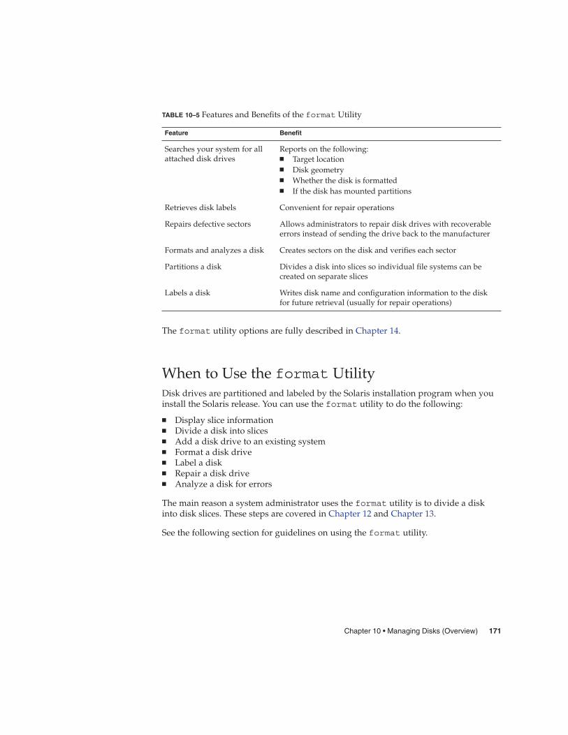
TABLE 10–5 Features and Benefits of the format Utility
Feature Benefit
Searches your system for allattached disk drives
Reports on the following:� Target location� Disk geometry� Whether the disk is formatted� If the disk has mounted partitions
Retrieves disk labels Convenient for repair operations
Repairs defective sectors Allows administrators to repair disk drives with recoverableerrors instead of sending the drive back to the manufacturer
Formats and analyzes a disk Creates sectors on the disk and verifies each sector
Partitions a disk Divides a disk into slices so individual file systems can becreated on separate slices
Labels a disk Writes disk name and configuration information to the diskfor future retrieval (usually for repair operations)
The format utility options are fully described in Chapter 14.
When to Use the format UtilityDisk drives are partitioned and labeled by the Solaris installation program when youinstall the Solaris release. You can use the format utility to do the following:
� Display slice information� Divide a disk into slices� Add a disk drive to an existing system� Format a disk drive� Label a disk� Repair a disk drive� Analyze a disk for errors
The main reason a system administrator uses the format utility is to divide a diskinto disk slices. These steps are covered in Chapter 12 and Chapter 13.
See the following section for guidelines on using the format utility.
Chapter 10 • Managing Disks (Overview) 171

Guidelines for Using the format Utility
TABLE 10–6 The format Utility Guidelines
Task Guidelines For More Information
Format a disk � Any existing data is destroyed when youreformat a disk.
� The need for formatting a disk drive hasdropped as more and moremanufacturers ship their disk drivesformatted and partitioned. You might notneed to use the format utility when youadd a disk drive to an existing system.
� If a disk has been relocated and isdisplaying a lot of disk errors, you canattempt to reformat it, which willautomatically remap any bad sectors.
“How to Format a Disk”on page 183
Replace a systemdisk
� Data from the damaged system disk mustbe restored from a backup medium.Otherwise, the system will have to bereinstalled by using the installationprogram.
“SPARC: How to Connect aSystem Disk and Boot”on page 202 or “x86: Howto Connect a System Diskand Boot” on page 212 or, ifthe system must bereinstalled, Solaris 9 9/04Installation Guide
Divide a disk intoslices
� Any existing data is destroyed when yourepartition and relabel a disk withexisting slices.
� Existing data must be copied to backupmedia before the disk is repartitioned andrestored.
“SPARC: How to CreateDisk Slices and Label aDisk” on page 204 or “x86:How to Create Disk Slicesand Label a Disk” on page220
Add a secondarydisk to an existingsystem
� Any existing data must be restored frombackup media if the secondary disk isreformatted or repartitioned.
“SPARC: How to Connect aSecondary Disk and Boot”on page 203 or “x86: Howto Connect a SecondaryDisk and Boot” on page 213
172 System Administration Guide: Devices and File Systems • September 2004
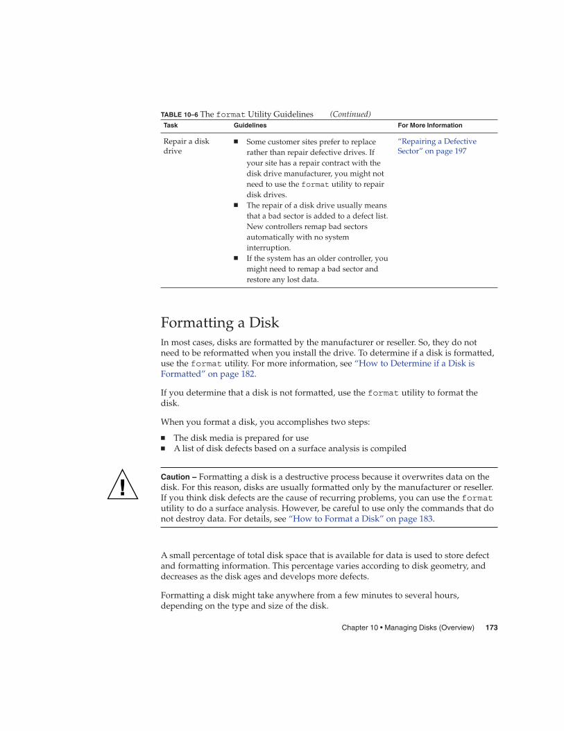
TABLE 10–6 The format Utility Guidelines (Continued)Task Guidelines For More Information
Repair a diskdrive
� Some customer sites prefer to replacerather than repair defective drives. Ifyour site has a repair contract with thedisk drive manufacturer, you might notneed to use the format utility to repairdisk drives.
� The repair of a disk drive usually meansthat a bad sector is added to a defect list.New controllers remap bad sectorsautomatically with no systeminterruption.
� If the system has an older controller, youmight need to remap a bad sector andrestore any lost data.
“Repairing a DefectiveSector” on page 197
Formatting a DiskIn most cases, disks are formatted by the manufacturer or reseller. So, they do notneed to be reformatted when you install the drive. To determine if a disk is formatted,use the format utility. For more information, see “How to Determine if a Disk isFormatted” on page 182.
If you determine that a disk is not formatted, use the format utility to format thedisk.
When you format a disk, you accomplishes two steps:
� The disk media is prepared for use� A list of disk defects based on a surface analysis is compiled
Caution – Formatting a disk is a destructive process because it overwrites data on thedisk. For this reason, disks are usually formatted only by the manufacturer or reseller.If you think disk defects are the cause of recurring problems, you can use the formatutility to do a surface analysis. However, be careful to use only the commands that donot destroy data. For details, see “How to Format a Disk” on page 183.
A small percentage of total disk space that is available for data is used to store defectand formatting information. This percentage varies according to disk geometry, anddecreases as the disk ages and develops more defects.
Formatting a disk might take anywhere from a few minutes to several hours,depending on the type and size of the disk.
Chapter 10 • Managing Disks (Overview) 173
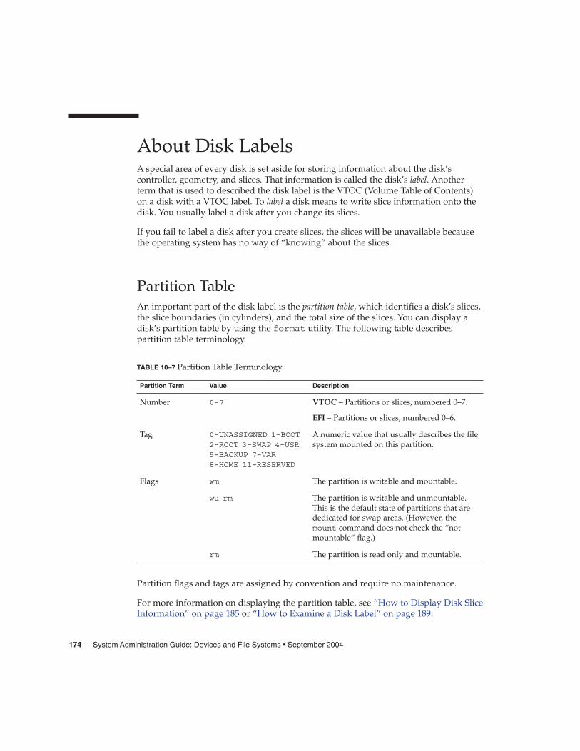
About Disk LabelsA special area of every disk is set aside for storing information about the disk’scontroller, geometry, and slices. That information is called the disk’s label. Anotherterm that is used to described the disk label is the VTOC (Volume Table of Contents)on a disk with a VTOC label. To label a disk means to write slice information onto thedisk. You usually label a disk after you change its slices.
If you fail to label a disk after you create slices, the slices will be unavailable becausethe operating system has no way of “knowing” about the slices.
Partition TableAn important part of the disk label is the partition table, which identifies a disk’s slices,the slice boundaries (in cylinders), and the total size of the slices. You can display adisk’s partition table by using the format utility. The following table describespartition table terminology.
TABLE 10–7 Partition Table Terminology
Partition Term Value Description
Number 0-7 VTOC – Partitions or slices, numbered 0–7.
EFI – Partitions or slices, numbered 0–6.
Tag 0=UNASSIGNED 1=BOOT2=ROOT 3=SWAP 4=USR5=BACKUP 7=VAR8=HOME 11=RESERVED
A numeric value that usually describes the filesystem mounted on this partition.
Flags wm The partition is writable and mountable.
wu rm The partition is writable and unmountable.This is the default state of partitions that arededicated for swap areas. (However, themount command does not check the “notmountable” flag.)
rm The partition is read only and mountable.
Partition flags and tags are assigned by convention and require no maintenance.
For more information on displaying the partition table, see “How to Display Disk SliceInformation” on page 185 or “How to Examine a Disk Label” on page 189.
174 System Administration Guide: Devices and File Systems • September 2004

Displaying Partition Table InformationThe following is an example of a partition table from a 4.0-Gbyte disk with a VTOClabel displayed from the format utility:
Total disk cylinders available: 8892 + 2 (reserved cylinders)
Part Tag Flag Cylinders Size Blocks0 root wm 1110 - 4687 1.61GB (0/3578/0) 33812101 swap wu 0 - 1109 512.00MB (0/1110/0) 10489502 backup wm 0 - 8891 4.01GB (0/8892/0) 84029403 unassigned wm 0 0 (0/0/0) 04 unassigned wm 0 0 (0/0/0) 05 unassigned wm 0 0 (0/0/0) 06 unassigned wm 0 0 (0/0/0) 0
7 home wm 4688 - 8891 1.89GB (0/4204/0) 3972780
The partition table displayed by the format utility contains the followinginformation:
Column Name Description
Part Partition (or slice number). See Table 10–7 for a description of thiscolumn.
Tag Partition tag. See Table 10–7 for a description of this column.
Flags Partition flag. See Table 10–7 for a description of this column.
Cylinders The starting and ending cylinder number for the slice.
Size The slice size in Mbytes.
Blocks The total number of cylinders and the total number of sectors per slicein the far right column.
First Sector EFI – The starting block number.
Last Sector EFI – The ending block number.
The following is an example of a EFI disk label displayed by using the prtvtoccommand.
# prtvtoc /dev/rdsk/c4t1d0s0* /dev/rdsk/c4t1d0s0 partition map** Dimensions:* 512 bytes/sector* 2576941056 sectors* 2576940989 accessible sectors** Flags:* 1: unmountable* 10: read-only
Chapter 10 • Managing Disks (Overview) 175

** First Sector Last* Partition Tag Flags Sector Count Sector Mount Directory
0 2 00 34 629145600 6291456331 4 00 629145634 629145600 12582912336 4 00 1258291234 1318633404 25769246378 11 00 2576924638 16384 2576941021
* Flags:* 1: unmountable* 10: read-only
*
The prtvtoc command provides the following information:
Column Name Description
Dimensions This section describes the physical dimensions of the disk drive.
Flags This section describes the flags listed in the partition tablesection. For a description of partition flags, see Table 10–7.
Partition (or Slice) Table This section contains the following information:
Partition Partition (or slice number). For a description of this column, seeTable 10–7.
Tag Partition tag. For a description of this column, see Table 10–7.
Flags Partition flag. For a description of this column, see Table 10–7.
First Sector The first sector of the slice.
Sector Count The total number of sectors in the slice.
Last Sector The last sector of the slice.
Mount Directory The last mount point directory for the file system.
Dividing a Disk Into SlicesThe format utility is most often used by system administrators to divide a disk intoslices. The steps are as follows:
� Determining which slices are needed� Determining the size of each slice� Using the format utility to divide the disk into slices� Labeling the disk with new slice information� Creating the file system for each slice
176 System Administration Guide: Devices and File Systems • September 2004
The easiest way to divide a disk into slices is to use the modify command from thepartition menu of the format utility. The modify command allows you to createslices by specifying the size of each slice without having to keep track of the startingcylinder boundaries. The modify command also keeps tracks of any disk space thatremains in the “free hog” slice.
Using the Free Hog SliceWhen you use the format utility to change the size of one or more disk slices, youdesignate a temporary slice that will expand and shrink to accommodate the resizingoperations.
This temporary slice donates, or “frees,” space when you expand a slice, and receives,or “hogs,” the discarded space when you shrink a slice. For this reason, the donor sliceis sometimes called the free hog.
The free hog slice exists only during installation or when you run the format utility.There is no permanent free hog slice during day-to-day operations.
For information on using the free hog slice, see “SPARC: How to Create Disk Slicesand Label a Disk” on page 204 or “x86: How to Create Disk Slices and Label a Disk”on page 220.
Chapter 10 • Managing Disks (Overview) 177

178 System Administration Guide: Devices and File Systems • September 2004

CHAPTER 11
Administering Disks (Tasks)
This chapter contains disk administration procedures. Many procedures described inthis chapter are optional if you are already familiar with how disks are managed onsystems running the Solaris release.
For information on the procedures associated with administering disks, see“Administering Disks (Task Map)” on page 179.
For overview information about disk management, see Chapter 10.
Administering Disks (Task Map)
Task Description For Instructions
Identify the disks on a system If you are not sure of the typesof disks on a system, use theformat utility to identify thedisk types.
“How to Identify the Disks ona System” on page 180
Format the disk Determine whether a disk isalready formatted by usingthe format utility.
“How to Determine if a Diskis Formatted” on page 182
In most cases, disks arealready formatted. Use theformat utility if you need toformat a disk.
“How to Format a Disk”on page 183
Display slice information Display slice information byusing the format utility.
“How to Display Disk SliceInformation” on page 185
179

Task Description For Instructions
Label the disk Create the disk label by usingthe format utility.
“How to Label a Disk”on page 187
Examine the disk label Examine the disk label byusing the prtvtoc command.
“How to Examine a DiskLabel” on page 189
Recover a corrupted disk label You can attempt to recover adisk label that was damageddue to a system or powerfailure.
“How to Recover a CorruptedDisk Label” on page 191
Create a format.dat entry Create a format.dat entryto support a third-party disk.
“How to Create aformat.dat Entry” on page194
Automatically configure aSCSI disk
You can automaticallyconfigure a SCSI disk with theSCSI-2 specification for diskdevice mode sense pages evenif the specific drive type is notlisted in the/etc/format.dat file.
“How to AutomaticallyConfigure a SCSI Drive”on page 195
Repair a defective disk sector Identify a defective disk sectorby using the format utility.
“How to Identify a DefectiveSector by Using SurfaceAnalysis” on page 197
If necessary, fix a defectivedisk sector
Fix a defective disk sector byusing the format utility.
“How to Repair a DefectiveSector” on page 198
Identifying Disks on a SystemUse the format utility to discover the types of disks that are connected to a system.You can also use the format utility to verify that a disk is known to the system. Forinformation on using the format utility, see Chapter 14.
� How to Identify the Disks on a System
1. Become superuser or assume an equivalent role.
2. Identify the disks that are recognized on the system with the format utility.
# format
Steps
180 System Administration Guide: Devices and File Systems • September 2004

The format utility displays a list of disks that it recognizes under AVAILABLEDISK SELECTIONS.
Identifying the Disks on a SystemThe following format output is from a system with one disk.
# formatSearching for disks...done
AVAILABLE DISK SELECTIONS:0. c0t0d0 <ST34321A cyl 8892 alt 2 hd 15 sec 63>
/pci@1f,0/pci@1,1/ide@3/dad@0,0
Specify disk (enter its number):
The format output associates a disk’s physical and logical device name to the disk’smarketing name, which appears in angle brackets <>. See the example below. Thismethod is an easy way to identify which logical device names represent the disks thatare connected to your system. For a description of logical and physical device names,see Chapter 9.
The following example uses a wildcard to display the disks that are connected to asecond controller.
# format /dev/rdsk/c2*AVAILABLE DISK SELECTIONS:
0. /dev/rdsk/c2t10d0s0 <SUN9.0G cyl 4924 alt 2 hd 27 sec 133>/sbus@3,0/SUNW,fas@3,8800000/sd@a,0
1. /dev/rdsk/c2t11d0s0 <SUN9.0G cyl 4924 alt 2 hd 27 sec 133>/sbus@3,0/SUNW,fas@3,8800000/sd@b,0
2. /dev/rdsk/c2t14d0s0 <SUN18G cyl 7506 alt 2 hd 19 sec 248>/sbus@3,0/SUNW,fas@3,8800000/sd@e,0
3. /dev/rdsk/c2t15d0s0 <SUN18G cyl 7506 alt 2 hd 19 sec 248>/sbus@3,0/SUNW,fas@3,8800000/sd@f,0
Specify disk (enter its number):
The following example identifies the disks on a SPARC based system.
# format0. c0t3d0 <SUN2.1G cyl 2733 alt 2 hd 19 sec 80>
/iommu@0,10000000/sbus@0,10001000/espdma@5,8400000/esp@5,8800000/sd@3,0
Specify disk (enter its number):
The format output identifies that disk 0 (target 3) is connected to the first SCSI hostadapter (espdma@...), which is connected to the first SBus device (sbus@0...). Theoutput also associates both the physical and logical device name to the disk’smarketing name, SUN2.1G.
The following example shows how to identify the disks on an x86 based system.
# formatAVAILABLE DISK SELECTIONS:0. c0d0 <DEFAULT cyl 615 alt 2 hd 64 sec 63>
Example 11–1
Chapter 11 • Administering Disks (Tasks) 181

/pci@0,0/pci-ide@7,1/ata@0/cmdk@0,01. c0d1 <DEFAULT cyl 522 alt 2 hd 32 sec 63>
/pci@0,0/pci-ide@7,1/ata@0/cmdk@1,02. c1d0 <DEFAULT cyl 817 alt 2 hd 256 sec 63>
/pci@0,0/pci-ide@7,1/ata@1/cmdk@0,0Specify disk (enter its number):
The format output identifies that disk 0 is connected to the first PCI host adapter(pci-ide@7...), which is connected to the ATA device (ata...). The format outputon an x86 based system does not identify disks by their marketing names.
Check the following table if the format utility did not recognize a disk.
� Go to Chapter 12 or Chapter 13.� Go to “Creating a format.dat Entry” on page 194.� Go to “How to Label a Disk” on page 187.� Connect the disk to the system by using your disk hardware documentation.
Formatting a DiskDisks are formatted by the manufacturer or reseller. They usually do not need to bereformatted when you install the drive.
A disk must be formatted before you can do the following:
� Write data to it. However, most disks are already formatted.� Use the Solaris installation program to install the system.
Caution – Formatting a disk is a destructive process because it overwrites data on thedisk. For this reason, disks are usually formatted only by the manufacturer or reseller.If you think disk defects are the cause of recurring problems, you can use the formatutility to do a surface analysis. However, be careful to use only the commands that donot destroy data.
� How to Determine if a Disk is Formatted
1. Become superuser or assume an equivalent role.
2. Invoke the format utility.
# format
3. Type the number of the disk that you want to check from the list displayed onyour screen.
See Also
Steps
182 System Administration Guide: Devices and File Systems • September 2004
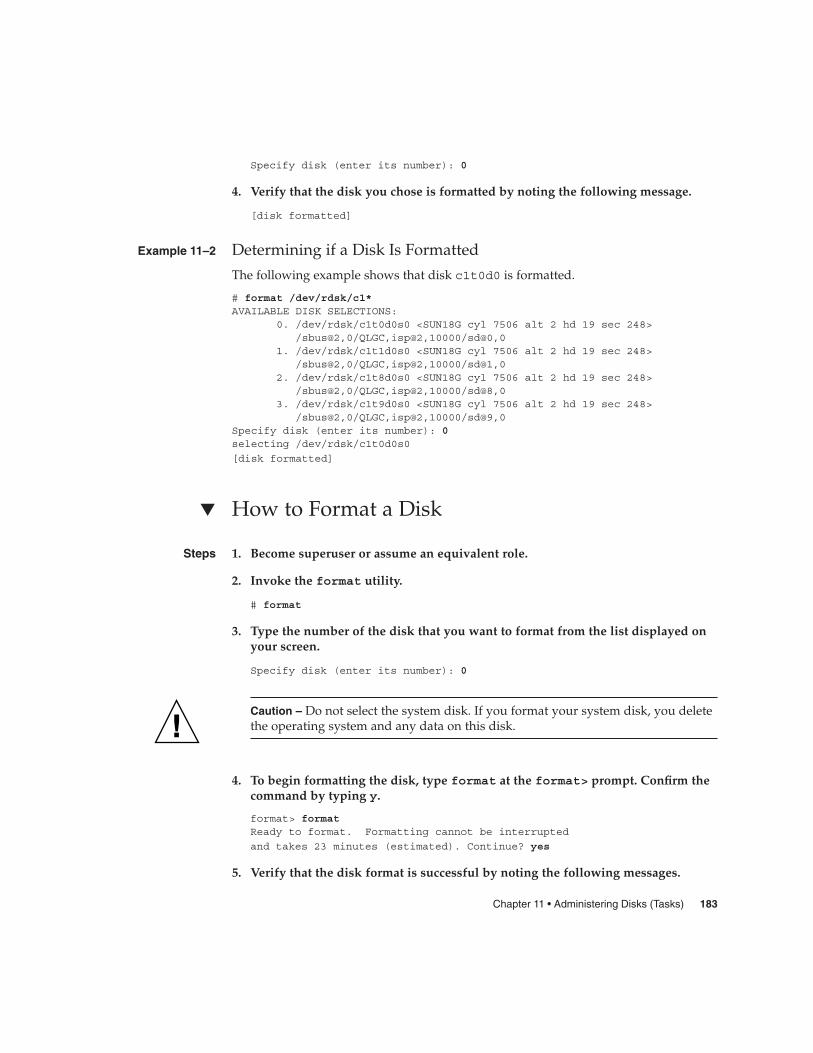
Specify disk (enter its number): 0
4. Verify that the disk you chose is formatted by noting the following message.
[disk formatted]
Determining if a Disk Is Formatted
The following example shows that disk c1t0d0 is formatted.
# format /dev/rdsk/c1*AVAILABLE DISK SELECTIONS:
0. /dev/rdsk/c1t0d0s0 <SUN18G cyl 7506 alt 2 hd 19 sec 248>/sbus@2,0/QLGC,isp@2,10000/sd@0,0
1. /dev/rdsk/c1t1d0s0 <SUN18G cyl 7506 alt 2 hd 19 sec 248>/sbus@2,0/QLGC,isp@2,10000/sd@1,0
2. /dev/rdsk/c1t8d0s0 <SUN18G cyl 7506 alt 2 hd 19 sec 248>/sbus@2,0/QLGC,isp@2,10000/sd@8,0
3. /dev/rdsk/c1t9d0s0 <SUN18G cyl 7506 alt 2 hd 19 sec 248>/sbus@2,0/QLGC,isp@2,10000/sd@9,0
Specify disk (enter its number): 0selecting /dev/rdsk/c1t0d0s0
[disk formatted]
� How to Format a Disk
1. Become superuser or assume an equivalent role.
2. Invoke the format utility.
# format
3. Type the number of the disk that you want to format from the list displayed onyour screen.
Specify disk (enter its number): 0
Caution – Do not select the system disk. If you format your system disk, you deletethe operating system and any data on this disk.
4. To begin formatting the disk, type format at the format> prompt. Confirm thecommand by typing y.
format> formatReady to format. Formatting cannot be interrupted
and takes 23 minutes (estimated). Continue? yes
5. Verify that the disk format is successful by noting the following messages.
Example 11–2
Steps
Chapter 11 • Administering Disks (Tasks) 183
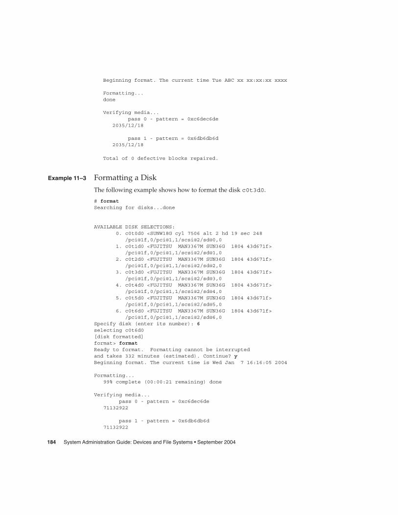
Beginning format. The current time Tue ABC xx xx:xx:xx xxxx
Formatting...done
Verifying media...pass 0 - pattern = 0xc6dec6de
2035/12/18
pass 1 - pattern = 0x6db6db6d2035/12/18
Total of 0 defective blocks repaired.
Formatting a Disk
The following example shows how to format the disk c0t3d0.
# formatSearching for disks...done
AVAILABLE DISK SELECTIONS:0. c0t0d0 <SUNW18G cyl 7506 alt 2 hd 19 sec 248
/pci@1f,0/pci@1,1/scsi@2/sd@0,01. c0t1d0 <FUJITSU MAN3367M SUN36G 1804 43d671f>
/pci@1f,0/pci@1,1/scsi@2/sd@1,02. c0t2d0 <FUJITSU MAN3367M SUN36G 1804 43d671f>
/pci@1f,0/pci@1,1/scsi@2/sd@2,03. c0t3d0 <FUJITSU MAN3367M SUN36G 1804 43d671f>
/pci@1f,0/pci@1,1/scsi@2/sd@3,04. c0t4d0 <FUJITSU MAN3367M SUN36G 1804 43d671f>
/pci@1f,0/pci@1,1/scsi@2/sd@4,05. c0t5d0 <FUJITSU MAN3367M SUN36G 1804 43d671f>
/pci@1f,0/pci@1,1/scsi@2/sd@5,06. c0t6d0 <FUJITSU MAN3367M SUN36G 1804 43d671f>
/pci@1f,0/pci@1,1/scsi@2/sd@6,0Specify disk (enter its number): 6selecting c0t6d0[disk formatted]format> formatReady to format. Formatting cannot be interruptedand takes 332 minutes (estimated). Continue? yBeginning format. The current time is Wed Jan 7 16:16:05 2004
Formatting...99% complete (00:00:21 remaining) done
Verifying media...pass 0 - pattern = 0xc6dec6de
71132922
pass 1 - pattern = 0x6db6db6d71132922
Example 11–3
184 System Administration Guide: Devices and File Systems • September 2004

Total of 0 defective blocks repaired.
format> quit
Displaying Disk SlicesYou can use the format utility to check whether a disk has the appropriate disk slices.If you determine that a disk does not contain the slices you want to use, use theformat utility to re-create them and label the disk. For information on creating diskslices, see “SPARC: How to Create Disk Slices and Label a Disk” on page 204 or “x86:How to Create Disk Slices and Label a Disk” on page 220.
Note – The format utility uses the term partition instead of slice.
� How to Display Disk Slice Information
1. Become superuser or assume an equivalent role.
2. Invoke the format utility.
# format
3. Type the number of the disk for which you want to display slice informationfrom the list displayed on your screen.
Specify disk (enter its number):1
4. Select the partition menu.
format> partition
5. Display the slice information for the current disk drive.
partition> print
6. Exit the format utility.
partition> qformat> q
#
7. Verify the displayed slice information by identifying specific slice tags andslices.
Steps
Chapter 11 • Administering Disks (Tasks) 185

If the screen output shows that no slice sizes are assigned, the disk probably doesnot have slices.
Displaying Disk Slice Information
The following example displays slice information for disk with a VTOC label.
# formatSearching for disks...doneSpecify disk (enter its number):1Selecting c0t0d0format> partitionpartition> printCurrent partition table (original):Total disk cylinders available: 8892 + 2 (reserved cylinders)
Part Tag Flag Cylinders Size Blocks0 root wm 1110 - 4687 1.61GB (0/3578/0) 33812101 swap wu 0 - 1109 512.00MB (0/1110/0) 10489502 backup wm 0 - 8891 4.01GB (0/8892/0) 84029403 unassigned wm 0 0 (0/0/0) 04 unassigned wm 0 0 (0/0/0) 05 unassigned wm 0 0 (0/0/0) 06 unassigned wm 0 0 (0/0/0) 07 home wm 4688 - 8891 1.89GB (0/4204/0) 3972780
partition> qformat> q
#
For a detailed description of the slice information in these examples, see Chapter 10.
The following example shows the slice information on a disk with an EFI label.
# formatSearching for disks...doneSpecify disk (enter its number): 9selecting c4t1d0[disk formatted]format> partitionpartition> printCurrent partition table (original):partition> qformat> qPart Tag Flag First Sector Size Last Sector0 root wm 34 300.00GB 6291456331 usr wm 629145634 300.00GB 12582912332 unassigned wm 0 0 03 unassigned wm 0 0 04 unassigned wm 0 0 05 unassigned wm 0 0 06 usr wm 1258291234 628.77GB 25769246378 reserved wm 2576924638 8.00MB 2576941021
Example 11–4
186 System Administration Guide: Devices and File Systems • September 2004
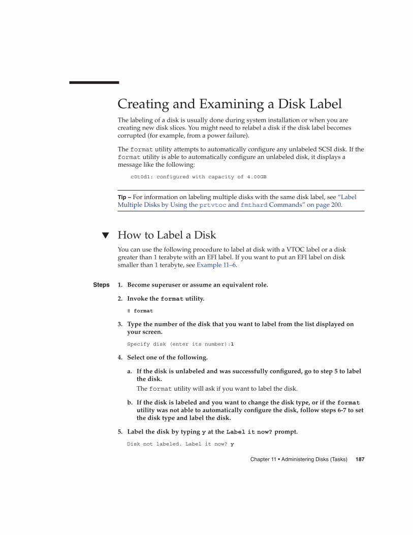
Creating and Examining a Disk LabelThe labeling of a disk is usually done during system installation or when you arecreating new disk slices. You might need to relabel a disk if the disk label becomescorrupted (for example, from a power failure).
The format utility attempts to automatically configure any unlabeled SCSI disk. If theformat utility is able to automatically configure an unlabeled disk, it displays amessage like the following:
c0t0d1: configured with capacity of 4.00GB
Tip – For information on labeling multiple disks with the same disk label, see “LabelMultiple Disks by Using the prtvtoc and fmthard Commands” on page 200.
� How to Label a DiskYou can use the following procedure to label at disk with a VTOC label or a diskgreater than 1 terabyte with an EFI label. If you want to put an EFI label on disksmaller than 1 terabyte, see Example 11–6.
1. Become superuser or assume an equivalent role.
2. Invoke the format utility.
# format
3. Type the number of the disk that you want to label from the list displayed onyour screen.
Specify disk (enter its number):1
4. Select one of the following.
a. If the disk is unlabeled and was successfully configured, go to step 5 to labelthe disk.
The format utility will ask if you want to label the disk.
b. If the disk is labeled and you want to change the disk type, or if the formatutility was not able to automatically configure the disk, follow steps 6-7 to setthe disk type and label the disk.
5. Label the disk by typing y at the Label it now? prompt.
Disk not labeled. Label it now? y
Steps
Chapter 11 • Administering Disks (Tasks) 187

The disk is now labeled. Go to step 10 to exit the format utility.
6. Enter type at the format> prompt.
format> type
The Available Drive Types menu is displayed.
7. Select a disk type from the list of possible disk types.
Specify disk type (enter its number)[12]: 12
Or, select 0 to automatically configure a SCSI-2 disk. For more information, see“How to Automatically Configure a SCSI Drive” on page 195.
8. Label the disk. If the disk is not labeled, the following message is displayed.
Disk not labeled. Label it now? y
Otherwise, you are prompted with this message:
Ready to label disk, continue? y
9. Verify the disk label.
format> verify
10. Exit the format utility.
partition> qformat> q
#
Labeling a Disk
The following example shows how to automatically configure and label a 1.05-Gbytedisk.
# formatc1t0d0: configured with capacity of 1002.09MB
AVAILABLE DISK SELECTIONS:0. c0t3d0 <SUN1.05 cyl 2036 alt 2 hd 14 sec 72>/iommu@f,e0000000/sbus@f,e0001000/espdma@f,400000/esp@f,800000/sd@1,01. c1t0d0 <SUN1.05 cyl 2036 alt 2 hd 14 sec 72>/iommu@f,e0000000/sbus@f,e0001000/espdma@f,400000/esp@f,800000/sd@1,0
Specify disk (enter its number): 1Disk not labeled. Label it now? yesformat> verify
#
Example 11–5
188 System Administration Guide: Devices and File Systems • September 2004

Labeling a Disk Less Than 1 Terabyte with an EFI LabelThe following example shows how to use the format -e command to label a disk lessthan 1 terabyte with an EFI label. Remember to verify that your layered softwareproducts will continue to work on systems with EFI-labeled disks. For generalinformation on EFI label restrictions, see “Restrictions of the EFI Disk Label” on page160.
# format -eSearching for disks...doneAVAILABLE DISK SELECTIONS:
1. c1t0d0 <SUNW18g cyl 7506 alt 2 hd 19 sec 248>/sbus@2,0/QLGC,isp@2,10000/sd@0,0
2. c1t1d0 <SUNW18g cyl 7506 alt 2 hd 19 sec 248>/sbus@2,0/QLGC,isp@2,10000/sd@1,0
3. c1t8d0 <SUNW18g cyl 7506 alt 2 hd 19 sec 248>/sbus@2,0/QLGC,isp@2,10000/sd@8,0
4. c1t9d0 <SUNW18g cyl 7506 alt 2 hd 19 sec 248>/sbus@2,0/QLGC,isp@2,10000/sd@9,0
Specify disk (enter its number): 4selecting c1t9d0[disk formatted]format> label[0] SMI Label[1] EFI LabelSpecify Label type[0]: 1Ready to label disk, continue? yes
format> quit
� How to Examine a Disk LabelExamine disk label information by using the prtvtoc command. For a detaileddescription of the disk label and the information that is displayed by the prtvtoccommand, see Chapter 10.
1. Become superuser or assume an equivalent role.
2. Display the disk label information.
# prtvtoc /dev/rdsk/device-name
device-name is the raw disk device you want to examine.
Examining a Disk LabelThe following example shows the disk label information for disk with a VTOC label.
# prtvtoc /dev/rdsk/c0t0d0s0* /dev/rdsk/c0t0d0s0 partition map** Dimensions:
Example 11–6
Steps
Example 11–7
Chapter 11 • Administering Disks (Tasks) 189

* 512 bytes/sector* 63 sectors/track* 15 tracks/cylinder* 945 sectors/cylinder* 8894 cylinders* 8892 accessible cylinders** Flags:* 1: unmountable* 10: read-only** First Sector Last* Partition Tag Flags Sector Count Sector Mount Directory
0 2 00 1048950 3381210 4430159 /1 3 01 0 1048950 10489492 5 00 0 8402940 8402939
7 8 00 4430160 3972780 8402939 /export/home
The following example shows the disk label information for disk with an EFI label.
# prtvtoc /dev/rdsk/c3t1d0s0* /dev/rdsk/c3t1d0s0 partition map** Dimensions:* 512 bytes/sector* 2479267840 sectors* 2479267773 accessible sectors** Flags:* 1: unmountable* 10: read-only** First Sector Last* Partition Tag Flags Sector Count Sector Mount Directory
0 2 00 34 262144 2621771 3 01 262178 262144 5243216 4 00 524322 2478727100 2479251421
8 11 00 2479251422 16384 2479267805
Recovering a Corrupted Disk LabelSometimes, a power or system failure causes a disk’s label to become unrecognizable.A corrupted disk label doesn’t always mean that the slice information or the disk’sdata must be recreated or restored.
The first step to recovering a corrupted disk label is to label the disk with the correctgeometry and disk type information. You can complete this step through the normaldisk labeling method, by using either automatic configuration or manual disk typespecification.
190 System Administration Guide: Devices and File Systems • September 2004

If the format utility recognizes the disk type, the next step is to search for a backuplabel to label the disk. Labeling the disk with the backup label labels the disk with thecorrect partitioning information, the disk type, and disk geometry.
� How to Recover a Corrupted Disk Label
1. Boot the system to single-user mode.
If necessary, boot the system from a local CD-ROM or the network in single-usermode to access the disk.
See Chapter 10, “Booting a System (Tasks),” in System Administration Guide: BasicAdministration or Chapter 11, “Booting a System (Tasks),” in System AdministrationGuide: Basic Administrationfor information on booting the system.
2. Relabel the disk.
# format
At this point, the format utility attempts to automatically configure any unlabeledSCSI disk. If the format utility is able to configure the unlabeled and corrupteddisk, it will display:
cwtxdy: configured with capacity of abcMB
The format utility then displays the list of disks on the system.
3. Type the number of the disk that you need to recover from the list displayed onyour screen.
Specify disk (enter its number): 1
4. Select one of the following to determine how to label the disk.
a. If the disk was configured successfully, follow steps 5 and 6. Then go to step12.
b. If the disk was not configured successfully, follow steps 7-11. Then go to step12.
5. Search for the backup label.
format> verifyWarning: Could not read primary label.Warning: Check the current partitioning and ’label’ the disk oruse the ’backup’ command.Backup label contents:Volume name = < >ascii name = <SUN1.05 cyl 2036 alt 2 hd 14 sec 72>pcyl = 2038ncyl = 2036acyl = 2
Steps
Chapter 11 • Administering Disks (Tasks) 191

nhead = 14nsect = 72Part Tag Flag Cylinders Size Blocks0 root wm 0 - 300 148.15MB (301/0/0) 3034081 swap wu 301 - 524 110.25MB (224/0/0) 2257922 backup wm 0 - 2035 1002.09MB (2036/0/0) 20522883 unassigned wm 0 0 (0/0/0) 04 unassigned wm 0 0 (0/0/0) 05 unassigned wm 0 0 (0/0/0) 06 usr wm 525 - 2035 743.70MB (1511/0/0) 1523088
7 unassigned wm 0 0 (0/0/0) 0
6. If the format utility was able to find a backup label and the backup labelcontents appear satisfactory, use the backup command to label the disk with thebackup label.
format> backupDisk has a primary label, still continue? y
Searching for backup labels...found.
Restoring primary label
The disk label has been recovered. Go to step 12.
7. If the format utility was not able to automatically configure the disk, specifythe disk type by using the type command.
format> type
The Available Drives Type menu is displayed.
8. Select 0 to automatically configure the disk, or select a disk type from the list ofpossible disk types.
Specify disk type (enter its number)[12]: 12
9. If the disk was successfully configured, reply with no when the format utilityasks if you want to label the disk.
Disk not labeled. Label it now? no
10. Use the verify command to search for backup labels.
format> verifyWarning: Could not read primary label.Warning: Check the current partitioning and ’label’ the diskor use the ’backup’ command...
.
11. If the format utility was able to find a backup label and the backup labelcontents appear satisfactory, use the backup command to label the disk with thebackup label.
format> backupDisk has a primary label, still continue? y
192 System Administration Guide: Devices and File Systems • September 2004
Searching for backup labels...found.
Restoring primary label
The disk label has been recovered.
12. Exit the format utility.
format> q
13. Verify the file systems on the recovered disk by using the fsck command.
For information on using the fsck command, see Chapter 20.
Adding a Third-Party DiskThe Solaris environment supports many third-party disks. However, you might needto supply either a device driver, a format.dat entry, or both for the disk to berecognized. Other options for adding disks are as follows:
� If you are adding a SCSI disk, you might to try the format utility’s automaticconfiguration feature. For more information, see “Automatically Configuring SCSIDisk Drives” on page 194.
� You might try hot-plugging a PCI, SCSI, or USB disk. For more information, seeChapter 5.
If the third-party disk is designed to work with standard SunOS-compatible devicedrivers, then creation of an appropriate format.dat entry should be enough to allowthe disk to be recognized by the format utility. In other cases, you need to load athird-party device driver to support the disk.
Note – Sun cannot guarantee that its format utility will work properly with allthird-party disk drivers. If the disk driver is not compatible with the Solaris formatutility, the disk drive vendor should supply you with a custom format program.
This section discusses what to do if some of this software support is missing. Typically,you discover that software support is missing when you invoke the format utilityand find that the disk type is not recognized.
Supply the missing software as described in this section, and then refer to theappropriate configuration procedure for adding system disks or secondary disks inChapter 12 or Chapter 13.
Chapter 11 • Administering Disks (Tasks) 193

Creating a format.dat EntryUnrecognized disks cannot be formatted without precise information about the disk’sgeometry and operating parameters. This information is supplied in the/etc/format.dat file.
Note – SCSI-2 drives do not require a format.dat entry. The format utilityautomatically configures the SCSI-2 drivers if the drives are powered on during areconfiguration boot. For step-by-step instructions on configuring a SCSI disk driveautomatically, see “How to Automatically Configure a SCSI Drive” on page 195.
If your disk is unrecognized, use a text editor to create an entry in format.dat forthe disk. You need to gather all the pertinent technical specifications about the diskand its controller before you start. This information should have been provided withthe disk. If not, contact the disk manufacturer or your supplier.
� How to Create a format.dat Entry
1. Become superuser or assume an equivalent role.
2. Make a copy of the /etc/format.dat file.
# cp /etc/format.dat /etc/format.dat.gen
3. Modify the /etc/format.dat file to include an entry for the third-party diskby using the format.dat information that is described in Chapter 14.
Use the disk’s hardware product documentation to gather the requiredinformation.
Automatically Configuring SCSI DiskDrivesThe format utility automatically configures SCSI disk drives even if that specific typeof drive is not listed in the /etc/format.dat file. This feature enables you toformat, create slices for, and label any disk driver that is compliant with the SCSI-2specification for disk device mode sense pages.
Other options for adding disks are:
Steps
194 System Administration Guide: Devices and File Systems • September 2004

� If you are adding a SCSI disk, you might to try the format utility’s automaticconfiguration feature. For more information, see “Automatically Configuring SCSIDisk Drives” on page 194.
� You might try hot-plugging a PCI, SCSI, or USB disk. For more information, seeChapter 5.
The following steps are involved in configuring a SCSI drive by using automaticconfiguration:
� Shutting down the system� Attaching the SCSI disk drive to the system� Turning on the disk drive� Performing a reconfiguration boot� Using the format utility to automatically configure the SCSI disk drive
After the reconfiguration boot, invoke the format utility. The format utility willattempt to configure the disk and, if successful, alert the user that the disk wasconfigured. For step-by-step instructions on configuring a SCSI disk driveautomatically, see “How to Automatically Configure a SCSI Drive” on page 195.
Here’s an example of a partition table for a 1.3-Gbyte SCSI disk drive that wasdisplayed by the format utility.
Part Tag Flag Cylinders Size Blocks0 root wm 0 - 96 64.41MB (97/0/0)1 swap wu 97 - 289 128.16MB (193/0/0)2 backup wu 0 - 1964 1.27GB (1965/0/0)
6 usr wm 290 - 1964 1.09GB (1675/0/0)
For more information on using SCSI automatic configuration, see Chapter 14.
� How to Automatically Configure a SCSI Drive
1. Become superuser or equivalent role.
2. Create the /reconfigure file that will be read when the system is booted.
# touch /reconfigure
3. Shut down the system.
# shutdown -i0 -gn -y
-in Brings the system down to init level 0, the power-down state.
-gn Notifies logged-in users that they have n seconds before the system beginsto shut down.
-y Specifies that the command should run without user intervention.
The ok prompt is displayed after the system is shut down.
Steps
Chapter 11 • Administering Disks (Tasks) 195
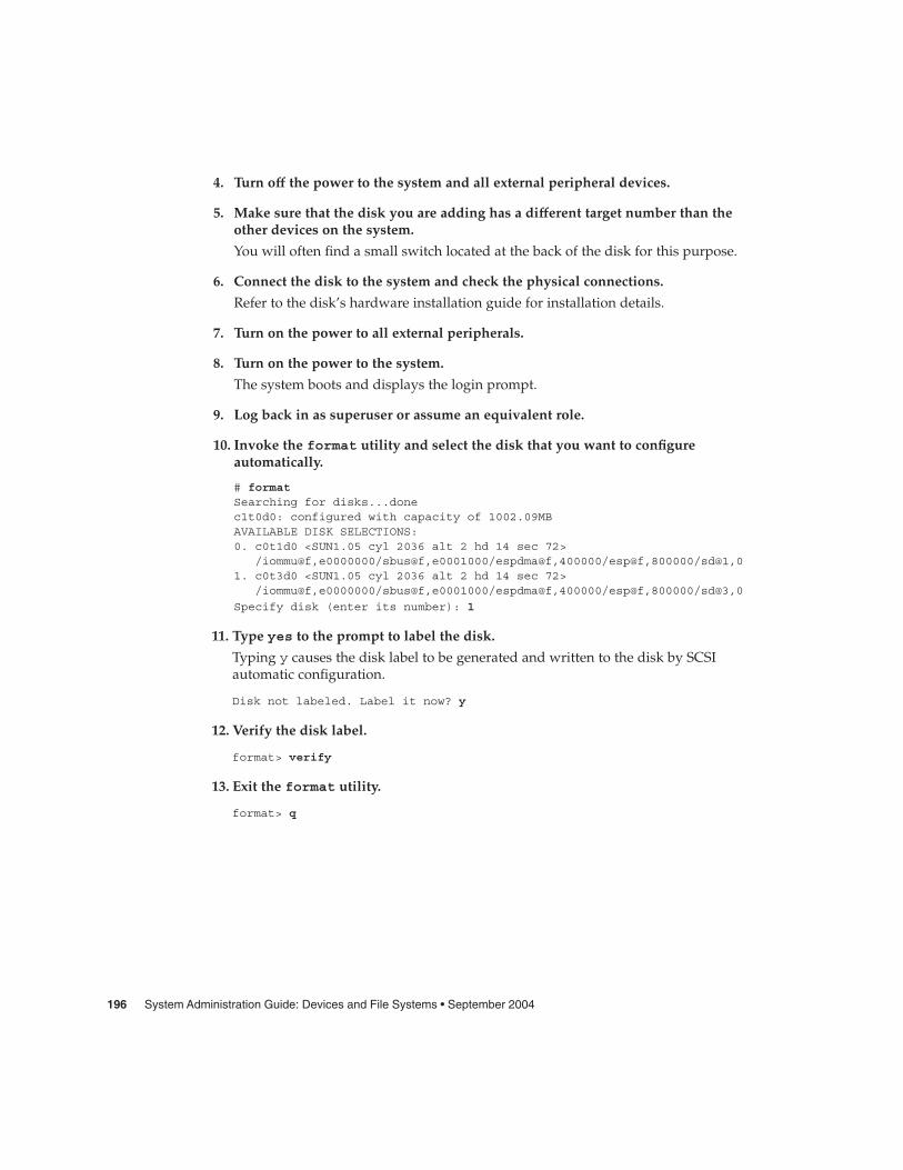
4. Turn off the power to the system and all external peripheral devices.
5. Make sure that the disk you are adding has a different target number than theother devices on the system.
You will often find a small switch located at the back of the disk for this purpose.
6. Connect the disk to the system and check the physical connections.
Refer to the disk’s hardware installation guide for installation details.
7. Turn on the power to all external peripherals.
8. Turn on the power to the system.
The system boots and displays the login prompt.
9. Log back in as superuser or assume an equivalent role.
10. Invoke the format utility and select the disk that you want to configureautomatically.
# formatSearching for disks...donec1t0d0: configured with capacity of 1002.09MBAVAILABLE DISK SELECTIONS:0. c0t1d0 <SUN1.05 cyl 2036 alt 2 hd 14 sec 72>
/iommu@f,e0000000/sbus@f,e0001000/espdma@f,400000/esp@f,800000/sd@1,01. c0t3d0 <SUN1.05 cyl 2036 alt 2 hd 14 sec 72>
/iommu@f,e0000000/sbus@f,e0001000/espdma@f,400000/esp@f,800000/sd@3,0
Specify disk (enter its number): 1
11. Type yes to the prompt to label the disk.
Typing y causes the disk label to be generated and written to the disk by SCSIautomatic configuration.
Disk not labeled. Label it now? y
12. Verify the disk label.
format> verify
13. Exit the format utility.
format> q
196 System Administration Guide: Devices and File Systems • September 2004
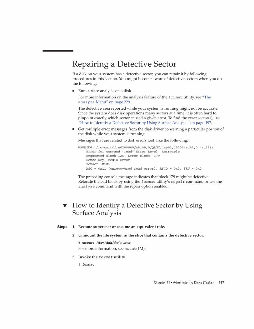
Repairing a Defective SectorIf a disk on your system has a defective sector, you can repair it by followingprocedures in this section. You might become aware of defective sectors when you dothe following:
� Run surface analysis on a disk
For more information on the analysis feature of the format utility, see “Theanalyze Menu” on page 229.
The defective area reported while your system is running might not be accurate.Since the system does disk operations many sectors at a time, it is often hard topinpoint exactly which sector caused a given error. To find the exact sector(s), use“How to Identify a Defective Sector by Using Surface Analysis” on page 197.
� Get multiple error messages from the disk driver concerning a particular portion ofthe disk while your system is running.
Messages that are related to disk errors look like the following:
WARNING: /io-unit@f,e0200000/sbi@0,0/QLGC,isp@1,10000/sd@3,0 (sd33):Error for command ’read’ Error Level: RetryableRequested Block 126, Error Block: 179Sense Key: Media ErrorVendor ’name’:ASC = 0x11 (unrecovered read error), ASCQ = 0x0, FRU = 0x0
The preceding console message indicates that block 179 might be defective.Relocate the bad block by using the format utility’s repair command or use theanalyze command with the repair option enabled.
� How to Identify a Defective Sector by UsingSurface Analysis
1. Become superuser or assume an equivalent role.
2. Unmount the file system in the slice that contains the defective sector.
# umount /dev/dsk/device-name
For more information, see mount(1M).
3. Invoke the format utility.
# format
Steps
Chapter 11 • Administering Disks (Tasks) 197
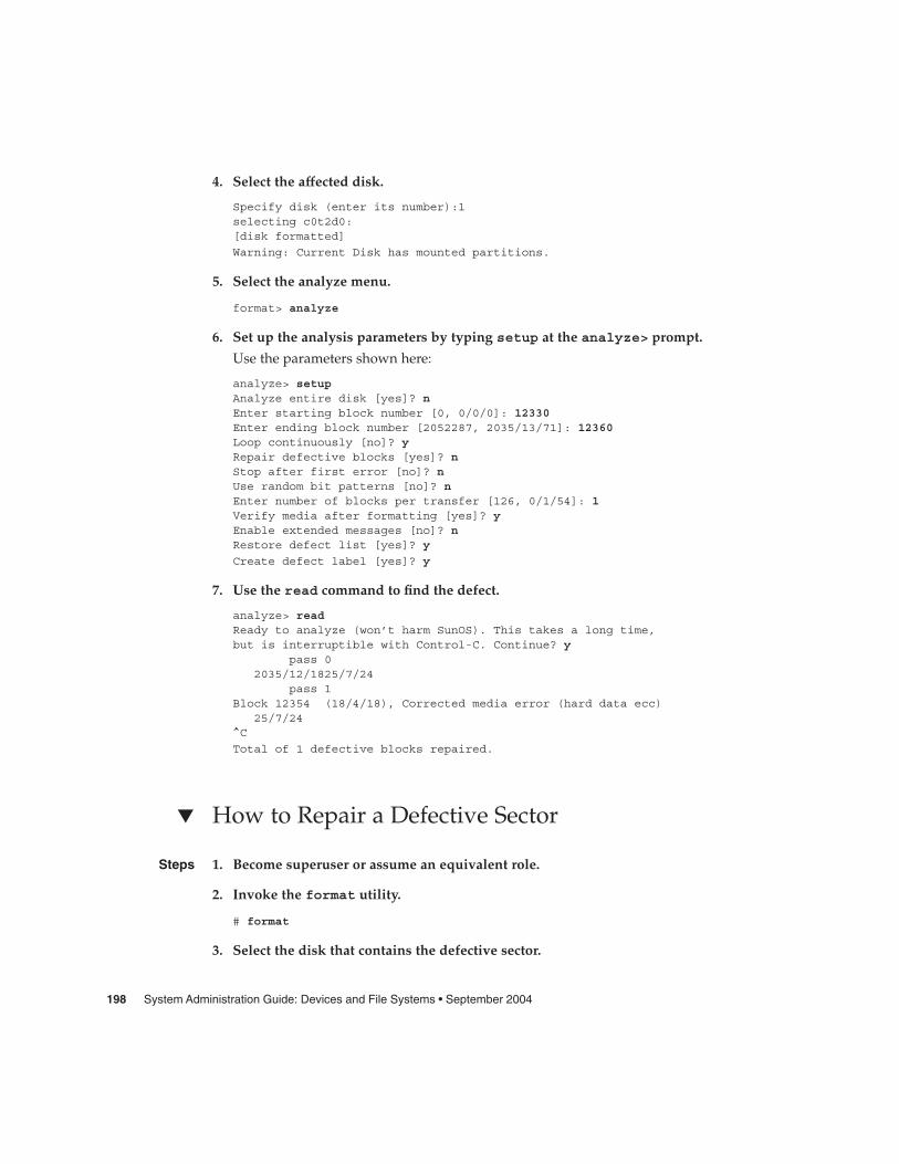
4. Select the affected disk.
Specify disk (enter its number):1selecting c0t2d0:[disk formatted]
Warning: Current Disk has mounted partitions.
5. Select the analyze menu.
format> analyze
6. Set up the analysis parameters by typing setup at the analyze> prompt.
Use the parameters shown here:
analyze> setupAnalyze entire disk [yes]? nEnter starting block number [0, 0/0/0]: 12330Enter ending block number [2052287, 2035/13/71]: 12360Loop continuously [no]? yRepair defective blocks [yes]? nStop after first error [no]? nUse random bit patterns [no]? nEnter number of blocks per transfer [126, 0/1/54]: 1Verify media after formatting [yes]? yEnable extended messages [no]? nRestore defect list [yes]? y
Create defect label [yes]? y
7. Use the read command to find the defect.
analyze> readReady to analyze (won’t harm SunOS). This takes a long time,but is interruptible with Control-C. Continue? y
pass 02035/12/1825/7/24
pass 1Block 12354 (18/4/18), Corrected media error (hard data ecc)
25/7/24^C
Total of 1 defective blocks repaired.
� How to Repair a Defective Sector
1. Become superuser or assume an equivalent role.
2. Invoke the format utility.
# format
3. Select the disk that contains the defective sector.
Steps
198 System Administration Guide: Devices and File Systems • September 2004

Specify disk (enter its number): 1selecting c0t3d0[disk formatted]
format>
4. Select the repair command.
format> repair
5. Type the defective block number.
Enter absolute block number of defect: 12354Ready to repair defect, continue? yRepairing block 12354 (18/4/18)...ok.
format>
If you are unsure of the format that is used to identify the defective sector, see“How to Identify a Defective Sector by Using Surface Analysis” on page 197 formore information.
Tips and Tricks for Managing DisksUse the following tips to help you manage disks more efficiently.
Debugging format SessionsInvoke format -M to enable extended and diagnostic messages for ATA and SCSIdevices.
In this example, the series of numbers under Inquiry: represent the hexadecimalvalue of the inquiry data that is displayed to the right of the numbers.
# format -MSearching for disks...doneAVAILABLE DISK SELECTIONS:0. c0t1d0 <SUN1.05 cyl 2036 alt 2 hd 14 sec 72>
/iommu@f,e0000000/sbus@f,e0001000/espdma@f,400000/esp@f,800000/sd@1,01. c0t3d0 <SUN1.05 cyl 2036 alt 2 hd 14 sec 72>
/iommu@f,e0000000/sbus@f,e0001000/espdma@f,400000/esp@f,800000/sd@3,0
Specify disk (enter its number): 0selecting c0t3d0[disk formatted]format> inquiryInquiry:00 00 02 02 8f 00 00 12 53 45 41 47 41 54 45 20 ........NAME....
Chapter 11 • Administering Disks (Tasks) 199

53 54 31 31 32 30 30 4e 20 53 55 4e 31 2e 30 35 ST11200N SUN1.0538 33 35 38 30 30 30 33 30 32 30 39 00 00 00 00 835800030209....00 00 00 00 00 00 00 00 00 00 00 00 00 00 00 00 ................00 00 00 00 00 00 00 00 00 00 00 00 00 00 00 00 ................00 00 00 00 00 00 00 00 00 00 00 00 00 00 00 00 ................00 43 6f 70 79 72 69 67 68 74 20 28 63 29 20 31 .Copyright (c) 139 39 32 20 53 65 61 67 61 74 65 20 41 6c 6c 20 992 NAME All72 69 67 68 74 73 20 72 65 73 65 72 76 65 64 20 rights reserved30 30 30 000Vendor: nameProduct: ST11200N SUN1.05Revision: 8358
format>
Label Multiple Disks by Using the prtvtoc andfmthard CommandsUse the prtvtoc and fmthard commands to label multiple disks with the same diskgeometry.
Use the following for loop in a script to copy a disk label from one disk andreplicate it on multiple disks.
# for i in x y z> do> prtvtoc /dev/rdsk/cwtxdysz | fmthard -s - /dev/rdsk/cwt${i}d0s2> done
EXAMPLE 11–8 Labeling Multiple Disks
In this example, the disk label from c2t0d0s0 is copied to four other disks.
# for i in 1 2 3 5> do> prtvtoc /dev/rdsk/c2t0d0s0 | fmthard -s - /dev/rdsk/c2t${i}d0s2> donefmthard: New volume table of contents now in place.fmthard: New volume table of contents now in place.fmthard: New volume table of contents now in place.fmthard: New volume table of contents now in place.
#
200 System Administration Guide: Devices and File Systems • September 2004
CHAPTER 12
SPARC: Adding a Disk (Tasks)
This chapter describes how to add a disk to a SPARC based system.
For information on the procedures associated with adding a disk to a SPARC basedsystem, see “SPARC: Adding a System Disk or a Secondary Disk (Task Map)” on page201.
For overview information about disk management, see Chapter 10. For step-by-stepinstructions on adding a disk to an x86 based system, see Chapter 13.
SPARC: Adding a System Disk or aSecondary Disk (Task Map)The following task map identifies the procedures for adding a disk to a SPARC basedsystem.
Task Description For Instructions
1. Connect the disk and boot System Disk
Connect the new disk andboot from a local or remoteSolaris CD or DVD.
“SPARC: How to Connect aSystem Disk and Boot”on page 202
Secondary Disk
Connect the new disk andperform a reconfigurationboot so that the system willrecognize the disk.
“SPARC: How to Connect aSecondary Disk and Boot”on page 203
201

Task Description For Instructions
2. Create slices and label thedisk
Create disk slices and labelthe disk if the diskmanufacturer has not alreadydone so.
“SPARC: How to Create DiskSlices and Label a Disk”on page 204
3. Create file systems Create UFS file systems on thedisk slices with the newfscommand. You must createthe root (/) or /usr filesystem, or both, for a systemdisk.
“SPARC: How to Create a UFSFile System” on page 209
4. Restore file systems Restore the root (/) or /usrfile system, or both, on thesystem disk. If necessary,restore file systems on thesecondary disk.
Chapter 25
5. Install boot block System Disk Only. Install theboot block on the root (/) filesystem, so that the system canboot.
“SPARC: How to Install aBoot Block on a System Disk”on page 209
SPARC: Adding a System Disk or a Secondary DiskA system disk contains the root (/) or /usr file systems, or both. If the disk thatcontains either of these file systems becomes damaged, you have two ways to recover:
� You can reinstall the entire Solaris environment.
� Or, you can replace the system disk and restore your file systems from a backupmedium.
A secondary disk does not contain the root (/) and /usr file systems. A secondarydisk usually contains space for user files. You can add a secondary disk to a system formore disk space, or you can replace a damaged secondary disk. If you replace asecondary disk on a system, you can restore the old disk’s data on the new disk.
� SPARC: How to Connect a System Disk and BootThis procedure assumes that the system is shut down.
1. Disconnect the damaged system disk from the system.
2. Make sure that the disk you are adding has a different target number than theother devices on the system.
Steps
202 System Administration Guide: Devices and File Systems • September 2004

You will often find a small switch located at the back of the disk for this purpose.
3. Connect the replacement system disk to the system and check the physicalconnections.
Refer to the disk’s hardware installation guide for installation details.
4. Follow the instructions in the following table, depending on whether you arebooting from a local Solaris CD or DVD or a remote Solaris CD or DVD fromthe network.
Boot Type Action
From a Solaris CD or DVD in a local drive 1. Make sure the CD or DVD is in the drive.
2. Boot from the media to single-user mode:
ok boot cdrom -s
From the network Boot from the network to single-user mode:
ok boot net -s
After a few minutes, the root prompt (#) is displayed.
After you boot the system, you can create slices and a disk label on the disk. Go to“SPARC: How to Create Disk Slices and Label a Disk” on page 204.
� SPARC: How to Connect a Secondary Disk andBoot
1. Become superuser or assume an equivalent role.
2. If the disk type is unsupported by the Solaris software, add the device driver forthe disk by following the instructions included with the hardware.
For information on creating a format.dat entry for the disk, see “How to Createa format.dat Entry” on page 194, if necessary.
3. Create the /reconfigure file that will be read when the system is booted.
# touch /reconfigure
The /reconfigure file causes the SunOS software to check for the presence ofany newly installed peripheral devices when you power on or boot your systemlater.
4. Shut down the system.
# shutdown -i0 -gn -y
See Also
Steps
Chapter 12 • SPARC: Adding a Disk (Tasks) 203

-i0 Changes to run level 0, the power-down state.
-gn Notifies logged-in users that they have n seconds before the system beginsto shut down.
-y Specifies that the command should run without user intervention.
The ok prompt is displayed after the Solaris operating system is shut down.
5. Turn off the power to the system and all external peripheral devices.
6. Make sure that the disk you are adding has a different target number than theother devices on the system.
You will often find a small switch located at the back of the disk for this purpose.
7. Connect the disk to the system and check the physical connections.
Refer to the disk’s hardware installation guide for installation details.
8. Turn on the power to all external peripherals.
9. Turn on the power to the system.
The system boots and displays the login prompt.
After you boot the system, you can create slices and a disk label on the disk. Go to“SPARC: How to Create Disk Slices and Label a Disk” on page 204.
� SPARC: How to Create Disk Slices and Label aDisk
1. Become superuser or assume an equivalent role.
2. Invoke the format utility.
# format
A list of available disks is displayed. For more information, see format(1M).
3. Type the number of the disk that you want to repartition from the list displayedon your screen.
Specify disk (enter its number): disk-number
disk-number is the number of the disk that you want to repartition.
4. Select the partition menu.
format> partition
5. Display the current partition (slice) table.
See Also
Steps
204 System Administration Guide: Devices and File Systems • September 2004

partition> print
6. Start the modification process.
partition> modify
7. Set the disk to all free hog.
Choose base (enter number) [0]? 1
For more information about the free hog slice, see “Using the Free Hog Slice”on page 177.
8. Create a new partition table by answering y when prompted to continue.
Do you wish to continue creating a new partition table based on
above table[yes]? y
9. Identify the free hog partition (slice) and the sizes of the slices when prompted.
When adding a system disk, you must set up slices for:
� root (slice 0) and swap (slice 1)� /usr (slice 6)
After you identify the slices, the new partition table is displayed.
For an example of creating disk slices, see Example 12–1.
10. Make the displayed partition table the current partition table by answering ywhen asked.
Okay to make this the current partition table[yes]? y
If you do not want the current partition table and you want to change it, answer noand go to Step 6.
11. Name the partition table.
Enter table name (remember quotes): "partition-name"
partition-name is the name for the new partition table.
12. Label the disk with the new partition table after you have finished allocatingslices on the new disk.
Ready to label disk, continue? yes
13. Quit the partition menu.
partition> q
14. Verify the disk label.
format> verify
15. Exit the format menu.
Chapter 12 • SPARC: Adding a Disk (Tasks) 205
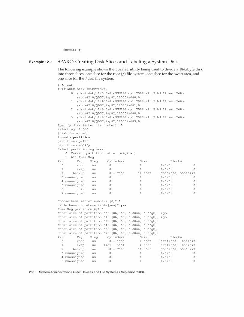
format> q
SPARC: Creating Disk Slices and Labeling a System Disk
The following example shows the format utility being used to divide a 18-Gbyte diskinto three slices: one slice for the root (/) file system, one slice for the swap area, andone slice for the /usr file system.
# formatAVAILABLE DISK SELECTIONS:
0. /dev/rdsk/c1t0d0s0 <SUN18G cyl 7506 alt 2 hd 19 sec 248>/sbus@2,0/QLGC,isp@2,10000/sd@0,0
1. /dev/rdsk/c1t1d0s0 <SUN18G cyl 7506 alt 2 hd 19 sec 248>/sbus@2,0/QLGC,isp@2,10000/sd@1,0
2. /dev/rdsk/c1t8d0s0 <SUN18G cyl 7506 alt 2 hd 19 sec 248>/sbus@2,0/QLGC,isp@2,10000/sd@8,0
3. /dev/rdsk/c1t9d0s0 <SUN18G cyl 7506 alt 2 hd 19 sec 248>/sbus@2,0/QLGC,isp@2,10000/sd@9,0
Specify disk (enter its number): 0selecting c1t0d0[disk formatted]format> partitionpartition> printpartition> modifySelect partitioning base:
0. Current partition table (original)1. All Free Hog
Part Tag Flag Cylinders Size Blocks0 root wm 0 0 (0/0/0) 01 swap wu 0 0 (0/0/0) 02 backup wu 0 - 7505 16.86GB (7506/0/0) 353682723 unassigned wm 0 0 (0/0/0) 04 unassigned wm 0 0 (0/0/0) 05 unassigned wm 0 0 (0/0/0) 06 usr wm 0 0 (0/0/0) 07 unassigned wm 0 0 (0/0/0) 0
Choose base (enter number) [0]? 1table based on above table[yes]? yesFree Hog partition[6]? 6Enter size of partition ’0’ [0b, 0c, 0.00mb, 0.00gb]: 4gbEnter size of partition ’1’ [0b, 0c, 0.00mb, 0.00gb]: 4gbEnter size of partition ’3’ [0b, 0c, 0.00mb, 0.00gb]:Enter size of partition ’4’ [0b, 0c, 0.00mb, 0.00gb]:Enter size of partition ’5’ [0b, 0c, 0.00mb, 0.00gb]:Enter size of partition ’7’ [0b, 0c, 0.00mb, 0.00gb]:Part Tag Flag Cylinders Size Blocks0 root wm 0 - 1780 4.00GB (1781/0/0) 83920721 swap wu 1781 - 3561 4.00GB (1781/0/0) 83920722 backup wu 0 - 7505 16.86GB (7506/0/0) 353682723 unassigned wm 0 0 (0/0/0) 04 unassigned wm 0 0 (0/0/0) 05 unassigned wm 0 0 (0/0/0) 0
Example 12–1
206 System Administration Guide: Devices and File Systems • September 2004

6 usr wm 3562 - 7505 8.86GB (3944/0/0) 185841287 unassigned wm 0 0 (0/0/0) 0
Okay to make this the current partition table[yes]? yesEnter table name (remember quotes): "disk0"Ready to label disk, continue? yespartition> quitformat> verify
format> quit
SPARC: Creating Disk Slices and Labeling a Secondary Disk
The following example shows the format utility being used to divide a 18-Gbyte diskinto one slice for the /export/home file system.
# format /dev/rdsk/c1*AVAILABLE DISK SELECTIONS:
0. /dev/rdsk/c1t0d0s0 <SUN18G cyl 7506 alt 2 hd 19 sec 248>/sbus@2,0/QLGC,isp@2,10000/sd@0,0
1. /dev/rdsk/c1t1d0s0 <SUN18G cyl 7506 alt 2 hd 19 sec 248>/sbus@2,0/QLGC,isp@2,10000/sd@1,0
2. /dev/rdsk/c1t8d0s0 <SUN18G cyl 7506 alt 2 hd 19 sec 248>/sbus@2,0/QLGC,isp@2,10000/sd@8,0
3. /dev/rdsk/c1t9d0s0 <SUN18G cyl 7506 alt 2 hd 19 sec 248>/sbus@2,0/QLGC,isp@2,10000/sd@9,0
Specify disk (enter its number): 1selecting c1t1d0[disk formatted]format> partitionpartition> printpartition> modifySelect partitioning base:
0. Current partition table (original)1. All Free Hog
Choose base (enter number) [0]? 1Part Tag Flag Cylinders Size Blocks0 root wm 0 0 (0/0/0) 01 swap wu 0 0 (0/0/0) 02 backup wu 0 - 7505 16.86GB (7506/0/0) 353682723 unassigned wm 0 0 (0/0/0) 04 unassigned wm 0 0 (0/0/0) 05 unassigned wm 0 0 (0/0/0) 06 usr wm 0 0 (0/0/0) 07 unassigned wm 0 0 (0/0/0) 0
Do you wish to continue creating a new partitiontable based on above table[yes]? yFree Hog partition[6]? 7Enter size of partition ’0’ [0b, 0c, 0.00mb, 0.00gb]:Enter size of partition ’1’ [0b, 0c, 0.00mb, 0.00gb]:Enter size of partition ’3’ [0b, 0c, 0.00mb, 0.00gb]:Enter size of partition ’4’ [0b, 0c, 0.00mb, 0.00gb]:Enter size of partition ’5’ [0b, 0c, 0.00mb, 0.00gb]:
Example 12–2
Chapter 12 • SPARC: Adding a Disk (Tasks) 207
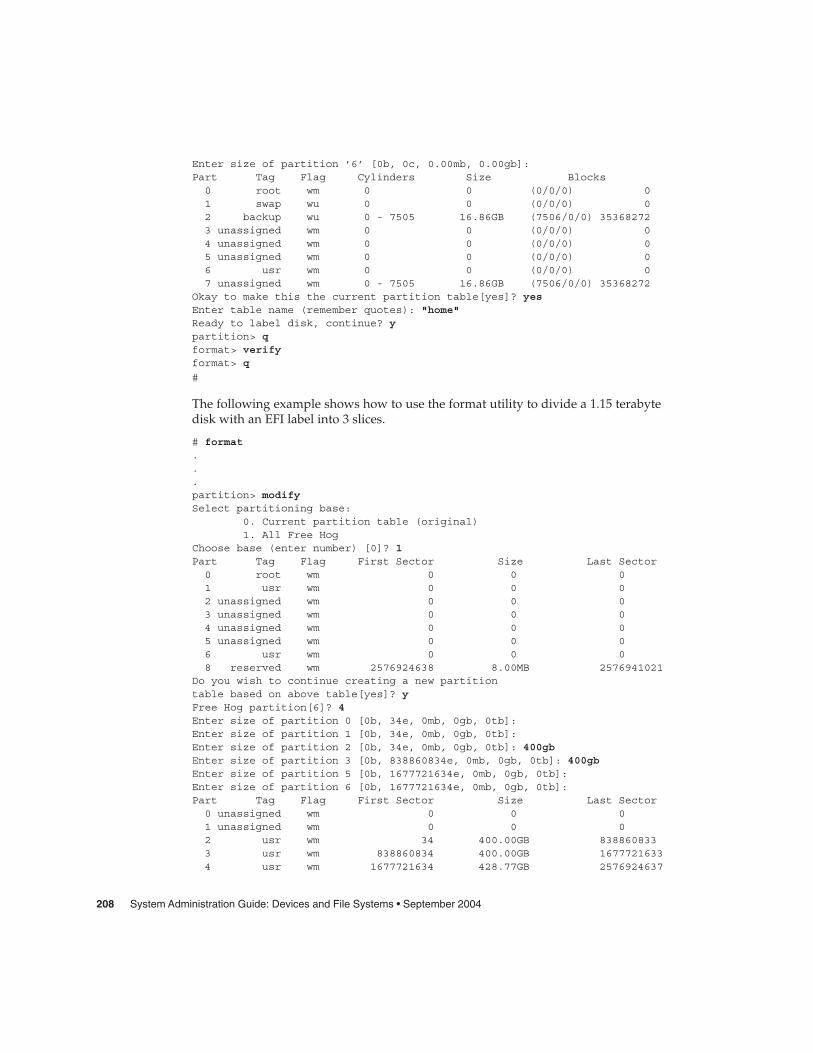
Enter size of partition ’6’ [0b, 0c, 0.00mb, 0.00gb]:Part Tag Flag Cylinders Size Blocks0 root wm 0 0 (0/0/0) 01 swap wu 0 0 (0/0/0) 02 backup wu 0 - 7505 16.86GB (7506/0/0) 353682723 unassigned wm 0 0 (0/0/0) 04 unassigned wm 0 0 (0/0/0) 05 unassigned wm 0 0 (0/0/0) 06 usr wm 0 0 (0/0/0) 07 unassigned wm 0 - 7505 16.86GB (7506/0/0) 35368272
Okay to make this the current partition table[yes]? yesEnter table name (remember quotes): "home"Ready to label disk, continue? ypartition> qformat> verifyformat> q
#
The following example shows how to use the format utility to divide a 1.15 terabytedisk with an EFI label into 3 slices.
# format...partition> modifySelect partitioning base:
0. Current partition table (original)1. All Free Hog
Choose base (enter number) [0]? 1Part Tag Flag First Sector Size Last Sector0 root wm 0 0 01 usr wm 0 0 02 unassigned wm 0 0 03 unassigned wm 0 0 04 unassigned wm 0 0 05 unassigned wm 0 0 06 usr wm 0 0 08 reserved wm 2576924638 8.00MB 2576941021
Do you wish to continue creating a new partitiontable based on above table[yes]? yFree Hog partition[6]? 4Enter size of partition 0 [0b, 34e, 0mb, 0gb, 0tb]:Enter size of partition 1 [0b, 34e, 0mb, 0gb, 0tb]:Enter size of partition 2 [0b, 34e, 0mb, 0gb, 0tb]: 400gbEnter size of partition 3 [0b, 838860834e, 0mb, 0gb, 0tb]: 400gbEnter size of partition 5 [0b, 1677721634e, 0mb, 0gb, 0tb]:Enter size of partition 6 [0b, 1677721634e, 0mb, 0gb, 0tb]:Part Tag Flag First Sector Size Last Sector0 unassigned wm 0 0 01 unassigned wm 0 0 02 usr wm 34 400.00GB 8388608333 usr wm 838860834 400.00GB 16777216334 usr wm 1677721634 428.77GB 2576924637
208 System Administration Guide: Devices and File Systems • September 2004

5 unassigned wm 0 0 06 unassigned wm 0 0 08 reserved wm 2576924638 8.00MB 2576941021
Ready to label disk, continue? yes
partition> q
After you create disk slices and label the disk, you can create file systems on the disk.Go to “SPARC: How to Create a UFS File System” on page 209.
� SPARC: How to Create a UFS File System
1. Become superuser or assume an equivalent role.
2. Create a file system for each slice.
# newfs /dev/rdsk/cwtxdysz
/dev/rdsk/cwtxdysx is the raw device for the file system to be created.
For more information about the newfs command, see Chapter 16 or newfs(1M).
3. Verify the new file system by mounting it.
# mount /dev/dsk/cwtxdysz /mnt
# ls lost+found
� System Disk – You need to restore the root (/) and /usr file systems on the disk.Go to Chapter 25.
� After the root (/) and /usr file systems are restored, install the boot block. Go to“SPARC: How to Install a Boot Block on a System Disk” on page 209.
� Secondary Disk – You might need to restore file systems on the new disk. Go toChapter 25. If you are not restoring file systems on the new disk, you are finishedadding a secondary disk.
� For information on making the file systems available to users, see Chapter 17.
� SPARC: How to Install a Boot Block on a SystemDisk
1. Become superuser or assume an equivalent role.
2. Install a boot block on the system disk.
# installboot /usr/platform/‘uname -i‘/lib/fs/ufs/bootblk /dev/rdsk/cwtxdys0
See Also
Steps
See Also
Steps
Chapter 12 • SPARC: Adding a Disk (Tasks) 209

/usr/platform/‘uname -i‘/lib/fs /ufs/bootblkIs the boot block code.
/dev/rdsk/cwtxdys0Is the raw device of the root (/) file system.
For more information, see installboot(1M).
3. Verify that the boot blocks are installed by rebooting the system to run level 3.
# init 6
SPARC: Installing a Boot Block on a System Disk
The following example shows how to install the boot block on an Ultra10 system.
# installboot /usr/platform/sun4u/lib/fs/ufs/bootblk /dev/rdsk/c0t0d0s0
Example 12–3
210 System Administration Guide: Devices and File Systems • September 2004
CHAPTER 13
x86: Adding a Disk (Tasks)
This chapter describes how to add a disk to an x86 based system.
For information on the procedures associated with adding a disk to an x86 basedsystem, see “x86: Adding a System Disk or a Secondary Disk (Task Map)” on page 211.
For overview information about disk management, see Chapter 10. For step-by-stepinstructions on adding a disk to a SPARC based system, see Chapter 12.
x86: Adding a System Disk or aSecondary Disk (Task Map)
Task Description For Instructions
1. Connect the disk and boot System Disk
Connect the new disk andboot from a local or remoteSolaris CD or DVD.
“x86: How to Connect aSystem Disk and Boot”on page 212
Secondary Disk
Connect the new disk andperform a reconfigurationboot, so that the system willrecognize the disk.
“x86: How to Connect aSecondary Disk and Boot”on page 213
211

Task Description For Instructions
2. Create slices and label thedisk
Create disk slices and labelthe disk if the diskmanufacturer has not alreadydone so.
“x86: How to Create a Solarisfdisk Partition” on page 215and “x86: How to Create DiskSlices and Label a Disk”on page 220
3. Create File Systems Create UFS file systems on thedisk slices with the newfscommand. You must createthe root (/) or /usr filesystem (or both) for a systemdisk.
“x86: How to Create FileSystems” on page 222
4. Restore File Systems Restore the root (/) or /usrfile system (or both) on thesystem disk. If necessary,restore file systems on thesecondary disk.
Chapter 25
5. Install Boot Block System Disk Only. Install theboot block on the root (/) filesystem so that the system canboot.
“x86: How to Install a BootBlock on a System Disk”on page 222
x86: Adding a System or Secondary DiskA system disk contains the root (/) or /usr file systems, or both. If the disk thatcontains either of these file systems becomes damaged, you have two ways to recover:
� You can reinstall the entire Solaris environment.� Or, you can replace the system disk and restore your file systems from a backup
medium.
A secondary disk doesn’t contain the root (/) and /usr file systems. A secondary diskusually contains space for user files. You can add a secondary disk to a system formore disk space, or you can replace a damaged secondary disk. If you replace asecondary disk on a system, you can restore the old disk’s data on the new disk.
� x86: How to Connect a System Disk and BootThis procedure assumes that the system is down.
1. Disconnect the damaged system disk from the system.Steps
212 System Administration Guide: Devices and File Systems • September 2004
2. Make sure that the disk you are adding has a different target number than theother devices on the system.You will often find a small switch located at the back of the disk for this purpose.
3. Connect the replacement system disk to the system and check the physicalconnections.
Refer to the disk’s hardware installation guide for installation details.
4. Follow steps a-e if you are booting from a local Solaris CD or DVD or a remoteSolaris CD or DVD from the network.
If you are booting from the network, skip step a.
a. If you are booting from a local Solaris CD or DVD, insert the Solarisinstallation CD or DVD into the drive.
b. Insert the Solaris boot diskette into the primary diskette drive (DOS drive A).
c. Press any key to reboot the system if the system displays the Type any keyto continue prompt. Or, use the reset button to restart the system if thesystem is shut down.
The Boot Solaris screen is displayed after a few minutes.
d. Select the CD-ROM drive or net(work) as the boot device from the BootSolaris screen.
The Current Boot Parameters screen is displayed.
e. Boot the system in single-user mode.
Select the type of installation: b -s
After a few minutes, the root prompt (#) is displayed.
After you boot the system, you can create an fdisk partition. Go to “x86: How toCreate a Solaris fdisk Partition” on page 215.
� x86: How to Connect a Secondary Disk and Boot
1. Become superuser or assume an equivalent role.
2. If the disk is unsupported by the Solaris software, add the device driver for thedisk by following the instructions included with the hardware.
3. Create the /reconfigure file that will be read when the system is booted.
# touch /reconfigure
The /reconfigure file causes the SunOS software to check for the presence ofany newly installed peripheral devices when you power on or boot your system
See Also
Steps
Chapter 13 • x86: Adding a Disk (Tasks) 213

later.
4. Shut down the system.
# shutdown -i0 -gn -y
-i0 Brings the system down to run level 0, the power-down state.
-gn Notifies logged-in users that they have n seconds before the system beginsto shut down.
-y Specifies that the command should run without user intervention.
The Type any key to continue prompt is displayed.
5. Turn off the power to the system and all external peripheral devices.
6. Make sure that the disk you are adding has a different target number than theother devices on the system.
You will often find a small switch located at the back of the disk for this purpose.
7. Connect the disk to the system and check the physical connections.
Refer to the disk’s hardware installation guide for installation details.
8. Turn on the power to all external peripherals.
9. Turn on the power to the system.
The system boots and displays the login prompt.
After you boot the system, you can create an fdisk partition. Go to “x86: How toCreate a Solaris fdisk Partition” on page 215.
x86: Guidelines for Creating an fdisk PartitionFollow these guidelines when you set up the fdisk partition.
� The disk can be divided into a maximum of four fdisk partitions. One ofpartitions must be a Solaris partition.
� The Solaris partition must be made the active partition on the disk. The activepartition is partition whose operating system will be booted by default at systemstartup.
� Solaris fdisk partitions must begin on cylinder boundaries.
� Solaris fdisk partitions must begin at cylinder 1, not cylinder 0, on the first diskbecause additional boot information, including the master boot record, is written insector 0.
See Also
214 System Administration Guide: Devices and File Systems • September 2004

� The Solaris fdisk partition can be the entire disk or you might want to make itsmaller to allow room for a DOS partition. You can also make a new fdiskpartition on a disk without disturbing existing partitions (if there is enough roomto create a new one).
x86 only – Solaris slices are sometimes called partitions. This book uses the term slice,but some Solaris documentation and programs might refer to a slice as a partition.
To avoid confusion, Solaris documentation tries to distinguish between fdiskpartitions (which are supported only on Solaris (x86 Platform Edition)) and thedivisions within the Solaris fdisk partition, which might be called slices or partitions.
� x86: How to Create a Solaris fdisk Partition
1. Read “x86: Guidelines for Creating an fdisk Partition” on page 214.
2. Become superuser or assume an equivalent role.
3. Invoke the format utility.
# format
For more information, see format(1M).
4. Type the number of the disk on which to create a Solaris fdisk partition fromthe list displayed on your screen.
Specify disk (enter its number): disk-number
disk-number is the number of the disk on which you want to create a Solaris fdiskpartition.
5. Select the fdisk menu.
format> fdisk
The fdisk menu that is displayed depends upon whether the disk has existingfdisk partitions. Determine the next step using the following table.
Task Go To For More Information
Create a Solaris fdisk partition tospan the entire disk.
Step 6 Example 13–1
Create a Solaris fdisk partition andpreserve one or more existingnon-Solaris fdisk partition.
Step 7 Example 13–2
Steps
Chapter 13 • x86: Adding a Disk (Tasks) 215

Task Go To For More Information
Create a Solaris fdisk partition andone or more additional non-Solarisfdisk partition.
Step 7 Example 13–3
6. Create and activate a Solaris fdisk partition that spans the entire disk byspecifying y at the prompt. Then, go to step 14.
The recommended default partitioning for your disk is:
a 100% “SOLARIS System” partition.
To select this, please type “y”. To partition your diskdifferently, type “n” and the “fdisk” program will
let you select other partitions. y
7. Specify n at the prompt if you do not want the Solaris fdisk partition to spanthe entire disk.
To select this, please type "y". To partition your diskdifferently, type "n" and the "fdisk" program will let youselect other partitions. nTotal disk size is 2694 cylinders
Cylinder size is 765 (512 byte) blocksCylinders
Partition Status Type Start End Length %========= ====== ======== ===== === ====== ===
THERE ARE NO PARTITIONS CURRENTLY DEFINED SELECT ONE OF THEFOLLOWING:
1. Create a partition2. Change Active (Boot from) partition3. Delete a partition4. Exit (Update disk configuration and exit)5. Cancel (Exit without updating disk configuration)
Enter Selection:
8. Select option 1, Create a partition, to create an fdisk partition.
Total disk size is 2694 cylindersCylinder size is 765 (512 byte) blocks
CylindersPartition Status Type Start End Length %========= ====== ======== ===== === ====== ===
THERE ARE NO PARTITIONS CURRENTLY DEFINED SELECT ONE OF THEFOLLOWING:
1. Create a partition2. Change Active (Boot from) partition3. Delete a partition4. Exit (Update disk configuration and exit)5. Cancel (Exit without updating disk configuration)
Enter Selection: 1
216 System Administration Guide: Devices and File Systems • September 2004

9. Create a Solaris fdisk partition by selecting 1(=Solaris).
Indicate the type of partition you want to create(1=SOLARIS, 2=UNIX, 3=PCIXOS, 4=Other, 8=DOSBIG)
(5=DOS12, 6=DOS16, 7=DOSEXT, 0=Exit) ? 1
10. Identify the percentage of the disk to be reserved for the Solaris fdisk partition.Keep in mind the size of any existing fdisk partitions when you calculate thispercentage.
Indicate the percentage of the disk you want this partition
to use (or enter "c" to specify in cylinders). nn
11. Activate the Solaris fdisk partition by typing y at the prompt.
Do you want this to become the Active partition? If so, it will beactivated each time you reset your computer or when you turn it on
again. Please type "y" or "n". y
The Enter Selection: prompt is displayed after the fdisk partition isactivated.
12. Select option 1, Create a partition, to create another fdisk partition.
See steps 9-11 for instructions on creating an fdisk partition.
13. Update the disk configuration and exit the fdisk menu from the selection menu.
Selection: 4
14. Relabel the disk by using the label command.
WARNING: Solaris fdisk partition changed - Please relabel the diskformat> labelReady to label disk, continue? yes
format>
15. Quit the format menu.
format> quit
x86: Creating a Solaris fdisk Partition That Spans the Entire DriveThe following example uses the format’s utility’s fdisk option to create a Solarisfdisk partition that spans the entire drive.
# formatSearching for disks...doneAVAILABLE DISK SELECTIONS:
0. c0d0 <DEFAULT cyl 2466 alt 2 hd 16 sec 63>/pci@0,0/pci-ide@7,1/ide@0/cmdk@0,0
1. c0d1 <DEFAULT cyl 522 alt 2 hd 32 sec 63>/pci@0,0/pci-ide@7,1/ide@0/cmdk@1,0
2. c1d0 <DEFAULT cyl 13102 alt 2 hd 16 sec 63>/pci@0,0/pci-ide@7,1/ide@1/cmdk@0,0
Specify disk (enter its number): 0
Example 13–1
Chapter 13 • x86: Adding a Disk (Tasks) 217

selecting c0d0Controller working list found[disk formatted]format> fdiskThe recommended default partitioning for your disk is:
a 100% "SOLARIS System" partition.
To select this, please type "y". To partition your diskdifferently, type "n" and the "fdisk" program will let youselect other partitions. y
WARNING: Solaris fdisk partition changed - Please relabel the diskformat> labelReady to label disk, continue? yes
format> quit
x86: Creating a Solaris fdisk Partition While Preserving an Existingfdisk PartitionThe following example shows how to create a Solaris fdisk partition on a disk thathas an existing DOS-BIG fdisk partition.
format> fdiskTotal disk size is 2694 cylindersCylinder size is 765 (512 byte) blocks
CylindersPartition Status Type Start End Length %========= ====== ======== ===== === ====== ===
1 DOS-BIG 1 538 538 20SELECT ONE OF THE FOLLOWING:
1. Create a partition2. Change Active (Boot from) partition3. Delete a partition4. Exit (Update disk configuration and exit)5. Cancel (Exit without updating disk configuration)
Enter Selection: 1Indicate the type of partition you want to create(1=SOLARIS, 2=UNIX, 3=PCIXOS, 4=Other, 8=DOSBIG)(5=DOS12, 6=DOS16, 7=DOSEXT, 0=Exit) ?1
Indicate the percentage of the disk you want this partitionto use (or enter "c" to specify in cylinders). 80Do you want this to become the Active partition? If so, it will beactivated each time you reset your computer or when you turn it onagain. Please type "y" or "n". yPartition 2 is now the Active partition Total disk size is 2694cylinders
Cylinder size is 765 (512 byte) blocksCylinders
Partition Status Type Start End Length %========= ====== ======== ===== === ====== ===
1 DOS-BIG 1 538 538 202 Active SOLARIS 539 2693 2155 80
SELECT ONE OF THE FOLLOWING:
Example 13–2
218 System Administration Guide: Devices and File Systems • September 2004

1. Create a partition2. Change Active (Boot from) partition3. Delete a partition4. Exit (Update disk configuration and exit)5. Cancel (Exit without updating disk configuration)
Enter Selection: Selection: 4WARNING: Solaris fdisk partition changed - Please relabel the diskformat> labelReady to label disk, continue? yes
format> q
x86: Creating a Solaris fdisk Partition and an Additional fdiskPartitionThis following example shows how to create a Solaris fdisk partition and a DOSBIGfdisk partition.
format> fdiskThe recommended default partitioning for your disk is:
a 100% "SOLARIS System" partition.To select this, please type "y". To partition your diskdifferently, type "n" and the "fdisk" program will let youselect other partitions. n
Total disk size is 2694 cylindersCylinder size is 765 (512 byte) blocks
CylindersPartition Status Type Start End Length %========= ====== ======== ===== === ====== ===
THERE ARE NO PARTITIONS CURRENTLY DEFINED SELECT ONE OF THE FOLLOWING:1. Create a partition2. Change Active (Boot from) partition3. Delete a partition4. Exit (Update disk configuration and exit)5. Cancel (Exit without updating disk configuration)
Enter Selection: 1Indicate the type of partition you want to create(1=SOLARIS, 2=UNIX, 3=PCIXOS, 4=Other, 8=DOSBIG)(5=DOS12, 6=DOS16, 7=DOSEXT, 0=Exit) ?8
Indicate the percentage of the disk you want this partitionto use (or enter "c" to specify in cylinders). 20Do you want this to become the Active partition? If so, it will beactivated each time you reset your computer or when you turn it onagain. Please type "y" or "n". n
Total disk size is 2694 cylindersCylinder size is 765 (512 byte) blocks
CylindersPartition Status Type Start End Length %========= ====== ======== ===== === ====== ===
1 DOS-BIG 1 538 538 20SELECT ONE OF THE FOLLOWING:
1. Create a partition2. Change Active (Boot from) partition3. Delete a partition4. Exit (Update disk configuration and exit)
Example 13–3
Chapter 13 • x86: Adding a Disk (Tasks) 219

5. Cancel (Exit without updating disk configuration)EnterSelection: 1Indicate the type of partition you want to create(1=SOLARIS, 2=UNIX, 3=PCIXOS, 4=Other, 8=DOSBIG)(5=DOS12, 6=DOS16, 7=DOSEXT, 0=Exit) ?1
Indicate the percentage of the disk you want this partitionto use (or enter "c" to specify in cylinders). 80Do you want this to become the Active partition? If so, it will beactivated each time you reset your computer or when you turn it onagain. Please type "y" or "n". yPartition 2 is now the Active partition Total disk size is 2694cylinders
Cylinder size is 765 (512 byte) blocksCylinders
Partition Status Type Start End Length %========= ====== ======== ===== === ====== ===
1 DOS-BIG 1 538 538 202 Active SOLARIS 539 2693 2155 80
SELECT ONE OF THE FOLLOWING:1. Create a partition2. Change Active (Boot from) partition3. Delete a partition4. Exit (Update disk configuration and exit)5. Cancel (Exit without updating disk configuration)
Enter Selection: 4
format> q
After you create a Solaris fdisk partition on the disk, you can create slices on thedisk. Go to “x86: How to Create Disk Slices and Label a Disk” on page 220.
� x86: How to Create Disk Slices and Label a Disk
1. Become superuser or assume an equivalent role.
2. Start the format utility.
# format
3. Type the number of the disk that you want to repartition from the list displayedon your screen.
Specify disk (enter its number): disk-number
disk-number is the number of the disk that you want to repartition.
4. Select the partition menu.
format> partition
5. Display the current partition (slice) table.
partition> print
See Also
Steps
220 System Administration Guide: Devices and File Systems • September 2004

6. Start the modification process.
partition> modify
7. Set the disk to all free hog.
Choose base (enter number) [0]? 1
For more information about the free hog slice, see “Using the Free Hog Slice”on page 177.
8. Create a new partition table by answering yes when prompted to continue.
Do you wish to continue creating a new partition
table based on above table[yes]? yes
9. Identify the free hog partition (slice) and the sizes of the slices when prompted.
When adding a system disk, you must set up slices for:
� root (slice 0) and swap (slice 1) and/or� /usr (slice 6)
After you identify the slices, the new partition table is displayed.
10. Make the displayed partition table the current partition table by answering yeswhen asked.
Okay to make this the current partition table[yes]? yes
If you don’t want the current partition table and you want to change it, answer noand go to Step 6.
11. Name the partition table.
Enter table name (remember quotes): "partition-name"
partition-name is the name for the new partition table.
12. Label the disk with the new partition table after you have finished allocatingslices on the new disk.
Ready to label disk, continue? yes
13. Quit the partition menu.
partition> quit
14. Verify the new disk label.
format> verify
15. Exit the format menu.
format> quit
After you create disk slices and label the disk, you can create file systems on the disk.Go to “x86: How to Create File Systems” on page 222.
See Also
Chapter 13 • x86: Adding a Disk (Tasks) 221
� x86: How to Create File Systems
1. Become superuser or assume an equivalent role.
2. Create a file system for each slice.
# newfs /dev/rdsk/cwtxdysz
/dev/rdsk/cwtxdysz is the raw device for the file system to be created.
For more information about the newfs command, see Chapter 16 or newfs(1M).
3. Verify the new file system by mounting.
# mount /dev/dsk/cwtxdysz /mnt# ls /mnt
lost+found
� System Disk – You need to restore the root (/) and /usr file systems on the disk.Go to Chapter 25.
� After the root (/) and /usr file systems are restored, install the boot block. Go to“x86: How to Install a Boot Block on a System Disk” on page 222.
� Secondary Disk – You might need to restore file systems on the new disk. Go toChapter 25. If you are not restoring file systems on the new disk, you are finishedadding a secondary disk.
� For information on making the file systems available to users, see Chapter 17.
� x86: How to Install a Boot Block on a System Disk
1. Become superuser or assume an equivalent role.
2. Install the boot block on the system disk.
# installboot /usr/platform/‘uname -i‘/lib/fs/ufs/pboot /usr/platform/
‘uname -i‘ /lib/fs/ufs/bootblk /dev/rdsk/cwtxdys2
/usr/platform/‘uname -i‘/lib/fs/ufs/pbootIs the partition boot file.
/usr/platform/‘uname -i‘/lib/fs/ufs/bootblkIs the boot block code.
/dev/rdsk/cwtxdys2Is the raw device name that represents the whole disk.
3. Verify that the boot blocks are installed by rebooting the system to run level 3.
# init 6
Steps
See Also
Steps
222 System Administration Guide: Devices and File Systems • September 2004

x86: Installing a Boot Block on a System Disk# installboot /usr/platform/i86pc/lib/fs/ufs/pboot
/usr/platform/i86pc/lib/fs/ufs/bootblk /dev/rdsk/c0t6d0s2
Example 13–4
Chapter 13 • x86: Adding a Disk (Tasks) 223

224 System Administration Guide: Devices and File Systems • September 2004
CHAPTER 14
The format Utility (Reference)
This chapter describes the format utility’s menu and commands.
This is a list of the reference information in this chapter.
� “Recommendations and Requirements for Using The format Utility” on page 225� “Format Menu and Command Descriptions” on page 226� “The format.dat File” on page 232� “Rules for Input to format Commands” on page 237� “Getting Help on the format Utility” on page 239
For a overview of when to use the format utility, see Chapter 10.
Recommendations and Requirements forUsing The format UtilityYou must be superuser or a member of an equivalent role to use the format utility. Ifyou are not superuser or have assumed an equivalent role, you will see the followingerror message when trying to use the format utility:
$ formatSearching for disks...doneNo permission (or no disks found)!
Keep the following guidelines in mind when using the format utility and you wantto preserve the existing data:
� Back up all files on the disk drive.� Save all your defect lists in files by using the format utility’s dump command. The
file name should include the drive type, model number, and serial number.� Save the paper copies of the manufacturer’s defect list that was shipped with your
drive.
225

Format Menu and CommandDescriptionsThe format main menu looks like the following:
FORMAT MENU:disk - select a disktype - select (define) a disk typepartition - select (define) a partition tablecurrent - describe the current diskformat - format and analyze the diskrepair - repair a defective sectorlabel - write label to the diskanalyze - surface analysisdefect - defect list managementbackup - search for backup labelsverify - read and display labelssave - save new disk/partition definitionsinquiry - show vendor, product and revisionvolname - set 8-character volume namequit
format>
The following table describes the format main menu items.
TABLE 14–1 The format Main Menu Item Descriptions
ItemCommand orMenu? Description
disk Command Lists all of the system’s drives. Also lets you choosethe disk you want to use in subsequent operations.This disk is referred to as the current disk.
type Command Identifies the manufacturer and model of the currentdisk. Also displays a list of known drive types.Choose the Auto configure option for all SCSI-2disk drives.
partition Menu Creates and modifies slices. For more information, see“The partition Menu” on page 228.
current Command Displays the following information about the currentdisk:� Device name and device type� Number of cylinders, alternate cylinders, heads
and sectors� Physical device name
226 System Administration Guide: Devices and File Systems • September 2004

TABLE 14–1 The format Main Menu Item Descriptions (Continued)
ItemCommand orMenu? Description
format Command Formats the current disk by using one of thesesources of information in this order:1. Information that is found in the format.dat file2. Information from the automatic configuration
process3. Information that you enter at the prompt if there
is no format.dat entry
This command does not apply to IDE disks. IDEdisks are pre–formatted by the manufacturer.
fdisk Menu x86 platform only: Runs the fdisk program to createa Solaris fdisk partition.
repair Command Repairs a specific block on the current disk.
label Command Writes a new label to the current disk.
analyze Menu Runs read, write, compare tests. For moreinformation, see “The analyze Menu” on page 229.
defect Menu Retrieves and prints defect lists. For moreinformation, see “The defect Menu” on page 231.This feature does not apply to IDE disks. IDE disksperform automatic defect management.
backup Command VTOC – Searches for backup labels.
EFI – Not supported.
verify Command Prints the following information about the currentdisk:� Device name and device type� Number of cylinders, alternate cylinders, heads
and sectors� Partition table
save Command VTOC –Saves new disk and partition information.
EFI – Not applicable.
inquiry Command Prints the vendor, product name, and revision level ofthe current drive (SCSI disks only).
volname Command Labels the disk with a new eight-character volumename.
quit Command Exits the format menu.
Chapter 14 • The format Utility (Reference) 227

The partition MenuThe partition menu looks similar to the following:
format> partitionPARTITION MENU:
0 - change ‘0’ partition1 - change ‘1’ partition2 - change ‘2’ partition3 - change ‘3’ partition4 - change ‘4’ partition5 - change ‘5’ partition6 - change ‘6’ partition7 - change ‘7’ partitionselect - select a predefined tablemodify - modify a predefined partition tablename - name the current tableprint - display the current tablelabel - write partition map and label to the diskquit
partition>
The following table describes the partition menu items.
TABLE 14–2 Descriptions for partition Menu Items
Sub-Command Description
change ‘n’ partition Lets you specify the following information for the new slice:� Identification tag� Permission flags� Starting cylinder� Size
select Lets you choose a predefined slice table.
modify Lets you change all the slices in the slice table. This commandis preferred over the individual change ‘x’ partitioncommands.
name Lets you specify a name for the current slice table.
print Displays the current slice table.
label Writes the slice map and the label to the current disk.
quit Exits the partition menu.
x86: The fdisk MenuThe fdisk menu appears on x86 based systems only and looks similar to thefollowing.
228 System Administration Guide: Devices and File Systems • September 2004

format> fdiskTotal disk size is 1855 cylindersCylinder size is 553 (512 byte) blocks
CylindersPartition Status Type Start End Length %========= ====== ======== ===== === ====== ===
1 DOS-BIG 0 370 371 202 Active SOLARIS 370 1851 1482 80
SELECT ONE OF THE FOLLOWING:1. Create a partition2. Change Active (Boot from) partition3. Delete a partition4. Exit (Update disk configuration and exit)5. Cancel (Exit without updating disk configuration)
Enter Selection:
The following table describes the fdisk menu items.
TABLE 14–3 x86: Descriptions for fdisk Menu Items
Menu Item Description
Create a partition Creates an fdisk partition. You must create a separatepartition for each operating system such as Solaris or DOS.There is a maximum of 4 partitions per disk. You areprompted for the size of the fdisk partition as a percentageof the disk.
Change Active partition Lets you specify the partition to be used for booting. Thismenu item identifies where the first stage boot program looksfor the second stage boot program.
Delete a partition Deletes a previously created partition. This commanddestroys all the data in the partition.
Exit Writes a new version of the partition table and exits thefdisk menu.
Cancel Exits the fdisk menu without modifying the partition table.
The analyze MenuThe analyze menu looks similar to the following.
format> analyze
ANALYZE MENU:read - read only test (doesn’t harm SunOS)refresh - read then write (doesn’t harm data)test - pattern testing (doesn’t harm data)write - write then read (corrupts data)compare - write, read, compare (corrupts data)
Chapter 14 • The format Utility (Reference) 229
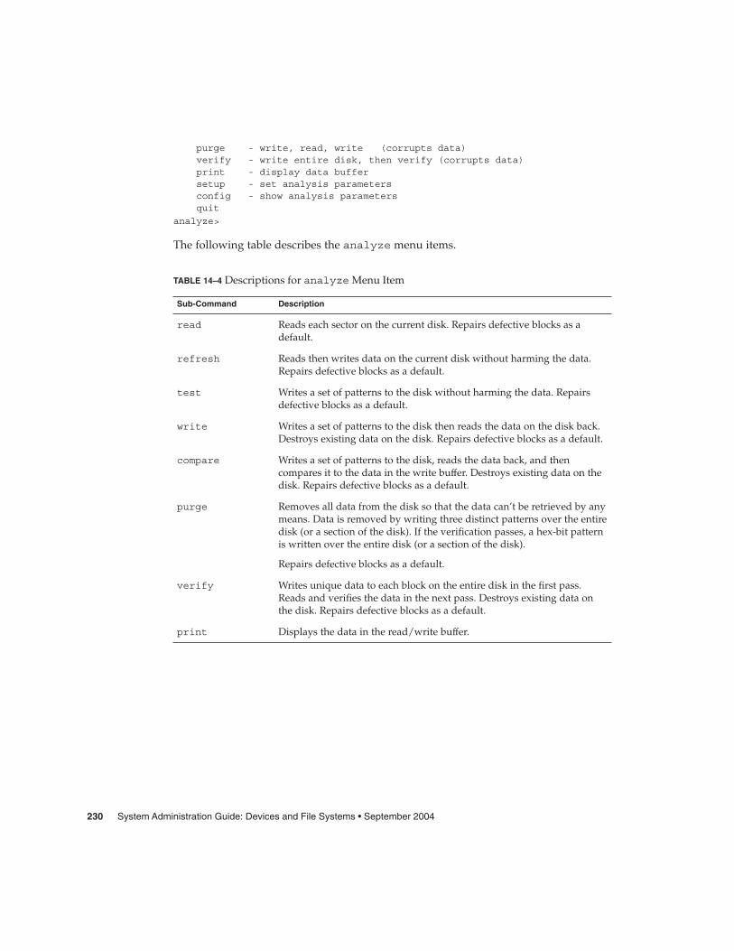
purge - write, read, write (corrupts data)verify - write entire disk, then verify (corrupts data)print - display data buffersetup - set analysis parametersconfig - show analysis parametersquit
analyze>
The following table describes the analyze menu items.
TABLE 14–4 Descriptions for analyze Menu Item
Sub-Command Description
read Reads each sector on the current disk. Repairs defective blocks as adefault.
refresh Reads then writes data on the current disk without harming the data.Repairs defective blocks as a default.
test Writes a set of patterns to the disk without harming the data. Repairsdefective blocks as a default.
write Writes a set of patterns to the disk then reads the data on the disk back.Destroys existing data on the disk. Repairs defective blocks as a default.
compare Writes a set of patterns to the disk, reads the data back, and thencompares it to the data in the write buffer. Destroys existing data on thedisk. Repairs defective blocks as a default.
purge Removes all data from the disk so that the data can’t be retrieved by anymeans. Data is removed by writing three distinct patterns over the entiredisk (or a section of the disk). If the verification passes, a hex-bit patternis written over the entire disk (or a section of the disk).
Repairs defective blocks as a default.
verify Writes unique data to each block on the entire disk in the first pass.Reads and verifies the data in the next pass. Destroys existing data onthe disk. Repairs defective blocks as a default.
print Displays the data in the read/write buffer.
230 System Administration Guide: Devices and File Systems • September 2004

TABLE 14–4 Descriptions for analyze Menu Item (Continued)Sub-Command Description
setup Lets you specify the following analysis parameters:
Analyze entire disk? yesStarting block number: depends on driveEnding block number: depends on driveLoop continuously? noNumber of passes: 2
Repair defective blocks? yesStop after first error? noUse random bit patterns? noNumber of blocks per transfer: 126 (0/n/nn)Verify media after formatting? yesEnable extended messages? noRestore defect list? yes
Restore disk label? yes
Defaults are shown in bold.
config Displays the current analysis parameters.
quit Exits the analyze menu.
The defect MenuThe defect menu looks similar to the following:
format> defect
DEFECT MENU:primary - extract manufacturer’s defect listgrown - extract manufacturer’s and repaired defects listsboth - extract both primary and grown defects listsprint - display working listdump - dump working list to filequit
defect>
The following table describes the defect menu items.
TABLE 14–5 The defect Menu Item Descriptions
Sub-Command Description
primary Reads the manufacturer’s defect list from the disk drive and updates thein-memory defect list.
grown Reads the grown defect list, which are defects that have been detectedduring analysis, and then updates the in-memory defect list.
Chapter 14 • The format Utility (Reference) 231

TABLE 14–5 The defect Menu Item Descriptions (Continued)Sub-Command Description
both Reads both the manufacturer’s defect list and the grown defect list, andthen updates the in-memory defect list.
print Displays the in-memory defect list.
dump Saves the in-memory defect list to a file.
quit Exits the defect menu.
The format.dat FileThe format.dat file that is shipped with the Solaris operating system supports manystandard disks. If your disk drive is not listed in the format.dat file, you can chooseto add an entry for it or adding entries with the format utility by selecting the typecommand and choosing the other option.
Adding an entry to the format.dat file can save time if the disk drive will be usedthroughout your site. To use the format.dat file on other systems, copy the file toeach system that will use the specific disk drive that you added to the format.datfile.
You should modify the /etc/format.dat file for your system if you have one of thefollowing:
� A disk that is not supported by the Solaris operating system
� A disk with a slice table that is different from the Solaris operating system’s defaultconfiguration
Note – Do not alter default entries in the /etc/format.dat file. If you want to alterthe default entries, copy the entry, give it a different name, and make the appropriatechanges to avoid confusion.
The /etc/format.dat is not applicable for disks with EFI labels.
Contents of the format.dat FileThe format.dat contains specific disk drive information that is used by the formatutility. Three items are defined in the format.dat file:
� Search paths
232 System Administration Guide: Devices and File Systems • September 2004

� Disk types� Slice tables
Syntax of the format.dat FileThe following syntax rules apply to the /etc/format.dat file:
� The pound sign (#) is the comment character. Any text on a line after a pound signis not interpreted by the format utility.
� Each definition in the format.dat file appears on a single logical line. If thedefinition is longer than one line long, all but the last line of the definition mustend with a backslash (\).
� A definition consists of a series of assignments that have an identifier on the leftside and one or more values on the right side. The assignment operator is the equalsign (=). The assignments within a definition must be separated by a colon (:).
� White space is ignored by the format utility. If you want an assigned value tocontain white space, enclose the entire value in double quotation marks ("). Thissyntax will cause the white space within the quotes to be preserved as part of theassignment value.
� Some assignments can have multiple values on the right hand side. Separate valuesby a comma.
Keywords in the format.dat FileThe format.dat file contains disk definitions that are read by the format utilitywhen it is started. Each definition starts with one of the following keywords:disk_type or partition. These keywords are described in the following table.
TABLE 14–6 Keyword Descriptions for the format.dat File
Keyword Use
disk_type Defines the controller and disk model. Each disk_type definition containsinformation that concerns the physical geometry of the disk. The default data filecontains definitions for the controllers and disks that the Solaris operating systemsupports.
You need to add a new disk_type only if you have an unsupported disk. Youcan add as many disk_type definitions to the data file as you want.
Chapter 14 • The format Utility (Reference) 233
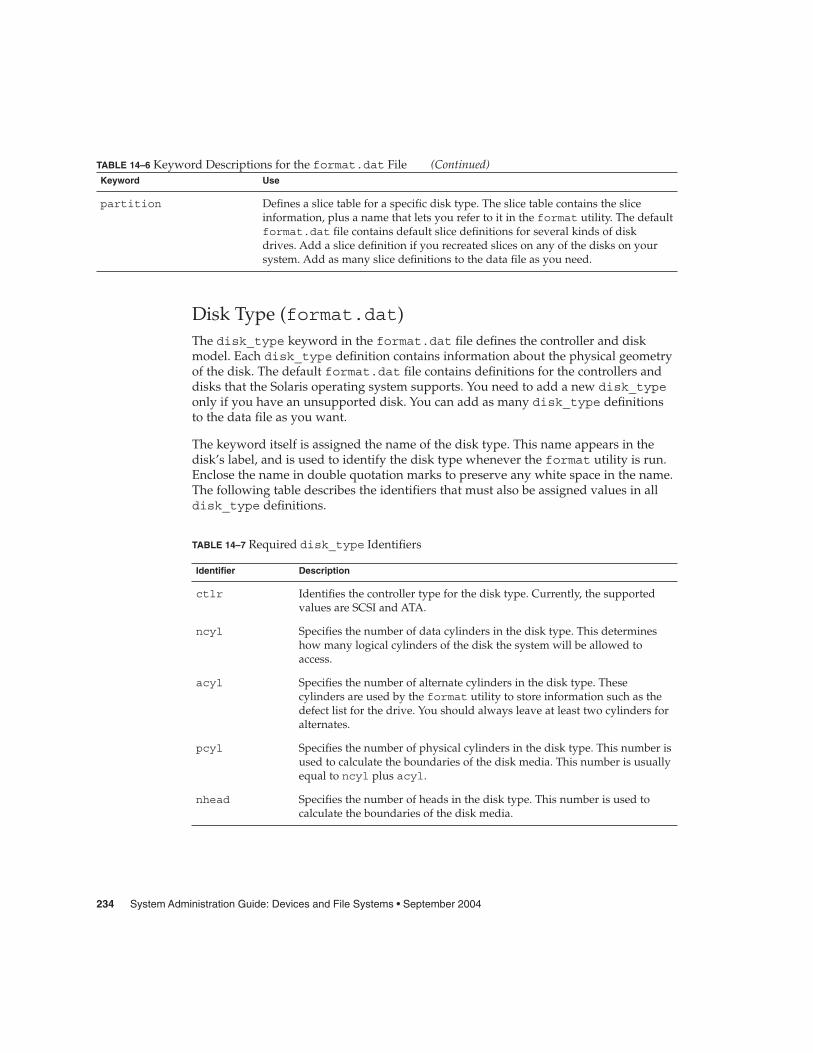
TABLE 14–6 Keyword Descriptions for the format.dat File (Continued)Keyword Use
partition Defines a slice table for a specific disk type. The slice table contains the sliceinformation, plus a name that lets you refer to it in the format utility. The defaultformat.dat file contains default slice definitions for several kinds of diskdrives. Add a slice definition if you recreated slices on any of the disks on yoursystem. Add as many slice definitions to the data file as you need.
Disk Type (format.dat)The disk_type keyword in the format.dat file defines the controller and diskmodel. Each disk_type definition contains information about the physical geometryof the disk. The default format.dat file contains definitions for the controllers anddisks that the Solaris operating system supports. You need to add a new disk_typeonly if you have an unsupported disk. You can add as many disk_type definitionsto the data file as you want.
The keyword itself is assigned the name of the disk type. This name appears in thedisk’s label, and is used to identify the disk type whenever the format utility is run.Enclose the name in double quotation marks to preserve any white space in the name.The following table describes the identifiers that must also be assigned values in alldisk_type definitions.
TABLE 14–7 Required disk_type Identifiers
Identifier Description
ctlr Identifies the controller type for the disk type. Currently, the supportedvalues are SCSI and ATA.
ncyl Specifies the number of data cylinders in the disk type. This determineshow many logical cylinders of the disk the system will be allowed toaccess.
acyl Specifies the number of alternate cylinders in the disk type. Thesecylinders are used by the format utility to store information such as thedefect list for the drive. You should always leave at least two cylinders foralternates.
pcyl Specifies the number of physical cylinders in the disk type. This number isused to calculate the boundaries of the disk media. This number is usuallyequal to ncyl plus acyl.
nhead Specifies the number of heads in the disk type. This number is used tocalculate the boundaries of the disk media.
234 System Administration Guide: Devices and File Systems • September 2004

TABLE 14–7 Required disk_type Identifiers (Continued)Identifier Description
nsect Specifies the number of data sectors per track in the disk type. Thisnumber is used to calculate the boundaries of the disk media. Note thatthis is only the data sectors. Any spares are not reflected in the number ofdata sections per track.
rpm The rotations per minute of the disk type. This information is put in thelabel and later used by the file system to calculate the optimal placementof file data.
Other identifiers might be necessary, depending on the controller. The following tabledescribes the identifiers that are required for SCSI controllers.
TABLE 14–8 disk_type Identifiers for SCSI Controllers
Identifier Description
fmt_time A number that Indicates how long it takes to format a given drive. See thecontroller manual for more information.
cache A number that controls the operation of the on-board cache while the formatutility is operating. See the controller manual for more information.
trks_zone A number that specifies how many tracks you have per defect zone, to be usedin alternate sector mapping. See the controller manual for more information.
asect A number that specifies how many sectors are available for alternate mappingwithin a given defect zone. See the controller manual for more information.
The following are examples of disk_type definitions:
disk_type = "SUN1.3G" \: ctlr = SCSI : fmt_time = 4 \: trks_zone = 17 : asect = 6 : atrks = 17 \: ncyl = 1965 : acyl = 2 : pcyl = 3500 : nhead = 17 : nsect = 80 \: rpm = 5400 : bpt = 44823
disk_type = "SUN2.1G" \: ctlr = SCSI : fmt_time = 4 \: ncyl = 2733 : acyl = 2 : pcyl = 3500 : nhead = 19 : nsect = 80 \: rpm = 5400 : bpt = 44823
disk_type = "SUN2.9G" \: ctlr = SCSI : fmt_time = 4 \: ncyl = 2734 : acyl = 2 : pcyl = 3500 : nhead = 21 : nsect = 99 \
: rpm = 5400
Partition or Slice Tables (format.dat)A partition table in the format.dat file defines a slice table for a specific disk type.
Chapter 14 • The format Utility (Reference) 235
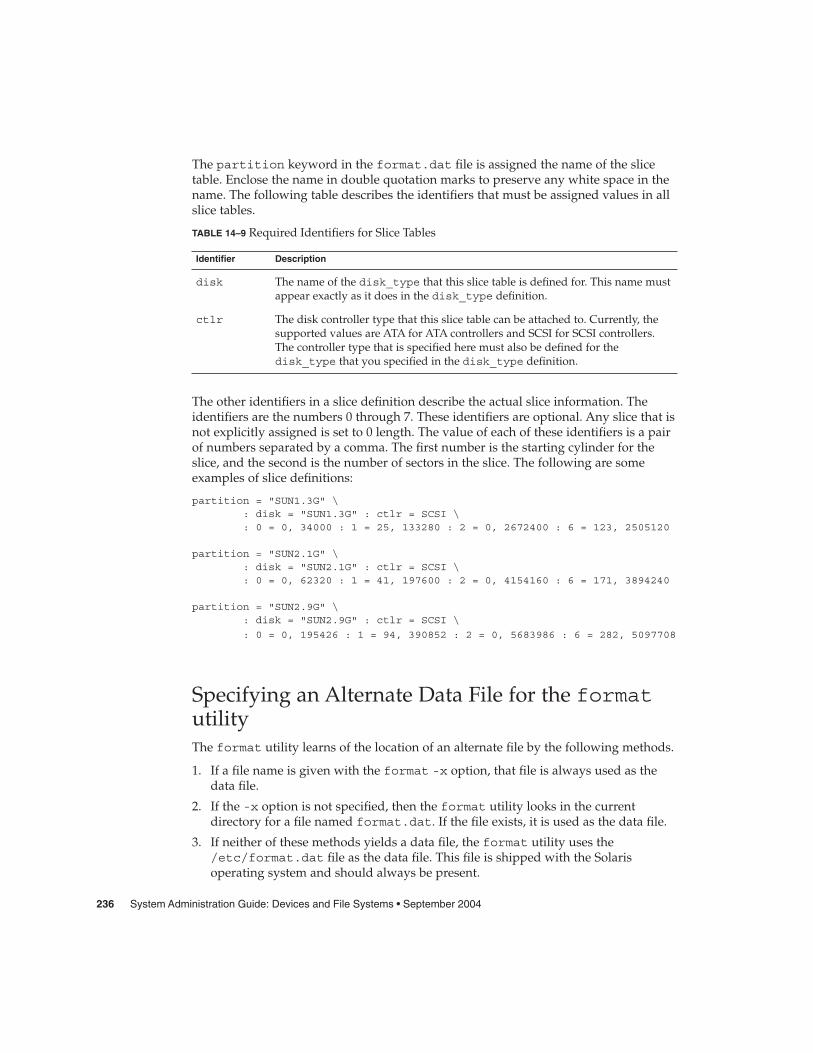
The partition keyword in the format.dat file is assigned the name of the slicetable. Enclose the name in double quotation marks to preserve any white space in thename. The following table describes the identifiers that must be assigned values in allslice tables.
TABLE 14–9 Required Identifiers for Slice Tables
Identifier Description
disk The name of the disk_type that this slice table is defined for. This name mustappear exactly as it does in the disk_type definition.
ctlr The disk controller type that this slice table can be attached to. Currently, thesupported values are ATA for ATA controllers and SCSI for SCSI controllers.The controller type that is specified here must also be defined for thedisk_type that you specified in the disk_type definition.
The other identifiers in a slice definition describe the actual slice information. Theidentifiers are the numbers 0 through 7. These identifiers are optional. Any slice that isnot explicitly assigned is set to 0 length. The value of each of these identifiers is a pairof numbers separated by a comma. The first number is the starting cylinder for theslice, and the second is the number of sectors in the slice. The following are someexamples of slice definitions:
partition = "SUN1.3G" \: disk = "SUN1.3G" : ctlr = SCSI \: 0 = 0, 34000 : 1 = 25, 133280 : 2 = 0, 2672400 : 6 = 123, 2505120
partition = "SUN2.1G" \: disk = "SUN2.1G" : ctlr = SCSI \: 0 = 0, 62320 : 1 = 41, 197600 : 2 = 0, 4154160 : 6 = 171, 3894240
partition = "SUN2.9G" \: disk = "SUN2.9G" : ctlr = SCSI \
: 0 = 0, 195426 : 1 = 94, 390852 : 2 = 0, 5683986 : 6 = 282, 5097708
Specifying an Alternate Data File for the formatutilityThe format utility learns of the location of an alternate file by the following methods.
1. If a file name is given with the format -x option, that file is always used as thedata file.
2. If the -x option is not specified, then the format utility looks in the currentdirectory for a file named format.dat. If the file exists, it is used as the data file.
3. If neither of these methods yields a data file, the format utility uses the/etc/format.dat file as the data file. This file is shipped with the Solarisoperating system and should always be present.
236 System Administration Guide: Devices and File Systems • September 2004

Rules for Input to format CommandsWhen you use the format utility, you need to provide various kinds of information.This section describes the rules for this information. For information on usingformat’s help facility when you enter data, see “Getting Help on the format Utility”on page 239.
Specifying Numbers to format CommandsSeveral places in the format utility require an number as input. You must eitherspecify the data or select a number from a list of choices. In either case, the helpfacility causes format to print the upper and lower limits of the number expected.Simply enter the number desired. The number is assumed to be in decimal formatunless a base is explicitly specified as part of the number (for example, 0x forhexadecimal).
The following are examples of integer input:
Enter number of passes [2]: 34
Enter number of passes [34] Oxf
Specifying Block Numbers to format CommandsWhenever you are required to specify a disk block number, there are two ways toenter the information:
� Block number as an integer� Block number in the cylinder/head/sector format
You can specify the information as an integer that represents the logical block number.You can specify the number in any base, but the default is decimal. The maximumoperator (a dollar sign, $) can also be used here to let the format utility select theappropriate value. Logical block format is used by the SunOS disk drivers in errormessages.
The other way to specify a block number is by the cylinder/head/sector designation.In this method, you must specify explicitly the three logical components of the blocknumber: the cylinder, head, and sector values. These values are still logical, but theyallow you to define regions of the disk that are related to the layout of the media.
If any of the cylinder/head/sector numbers are not specified, the value is assumed tobe zero. You can also use the maximum operator in place of any of the numbers andlet the format utility select the appropriate value. The following are some examplesof cylinder, head, and sector entries:
Chapter 14 • The format Utility (Reference) 237
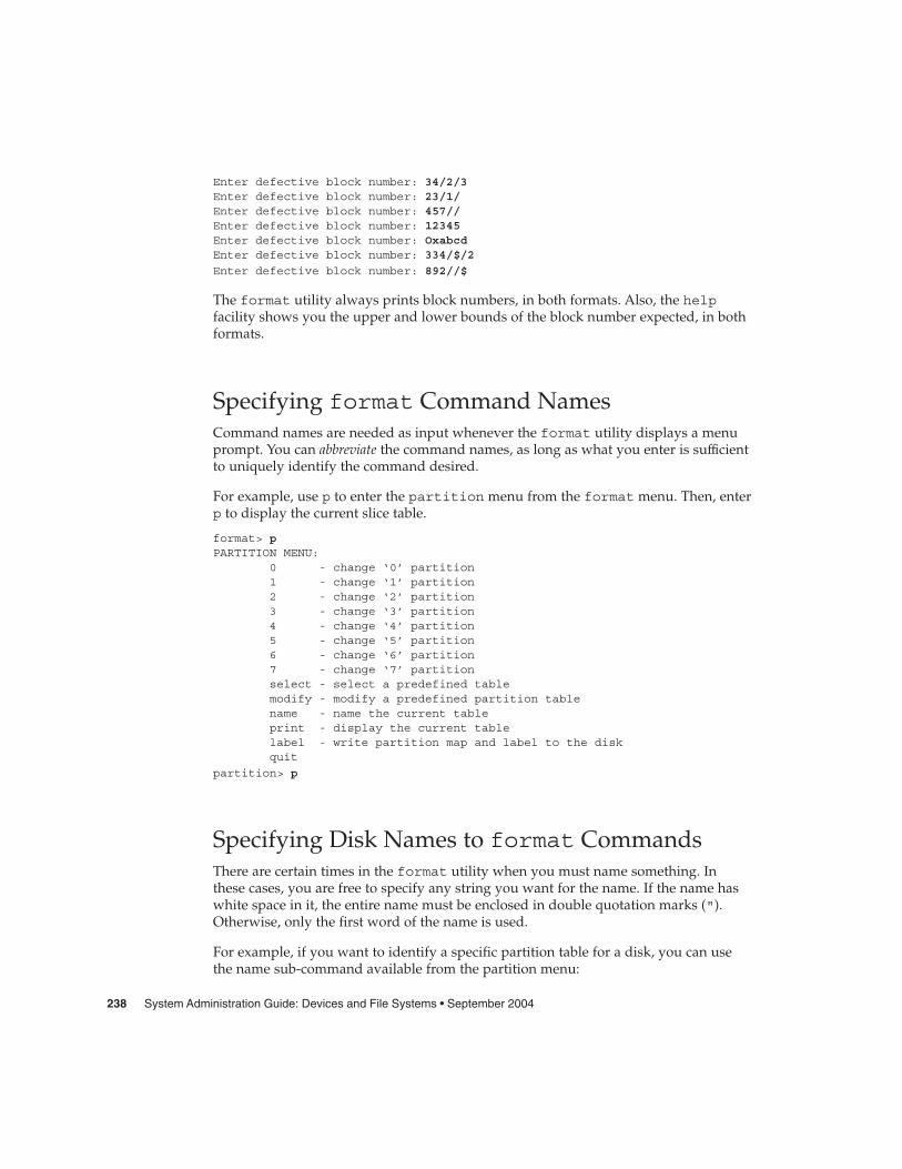
Enter defective block number: 34/2/3Enter defective block number: 23/1/Enter defective block number: 457//Enter defective block number: 12345Enter defective block number: OxabcdEnter defective block number: 334/$/2
Enter defective block number: 892//$
The format utility always prints block numbers, in both formats. Also, the helpfacility shows you the upper and lower bounds of the block number expected, in bothformats.
Specifying format Command NamesCommand names are needed as input whenever the format utility displays a menuprompt. You can abbreviate the command names, as long as what you enter is sufficientto uniquely identify the command desired.
For example, use p to enter the partition menu from the format menu. Then, enterp to display the current slice table.
format> pPARTITION MENU:
0 - change ‘0’ partition1 - change ‘1’ partition2 - change ‘2’ partition3 - change ‘3’ partition4 - change ‘4’ partition5 - change ‘5’ partition6 - change ‘6’ partition7 - change ‘7’ partitionselect - select a predefined tablemodify - modify a predefined partition tablename - name the current tableprint - display the current tablelabel - write partition map and label to the diskquit
partition> p
Specifying Disk Names to format CommandsThere are certain times in the format utility when you must name something. Inthese cases, you are free to specify any string you want for the name. If the name haswhite space in it, the entire name must be enclosed in double quotation marks (").Otherwise, only the first word of the name is used.
For example, if you want to identify a specific partition table for a disk, you can usethe name sub-command available from the partition menu:
238 System Administration Guide: Devices and File Systems • September 2004

partition> name
Enter table name (remember quotes): "new disk3"
Getting Help on the format UtilityThe format utility provides a help facility that you can use whenever the formatutility is expecting input. You can request help about what input is expected byentering a question mark (?). The format utility displays a brief description of whattype of input is needed.
If you enter a ? at a menu prompt, a list of available commands is displayed.
The man pages associated with the format utility include the following:
� format(1M) - Describes the basic format utility capabilities and providesdescriptions of all command-line variables.
� format.dat(4) - Describes disk drive configuration information for the formatutility.
Chapter 14 • The format Utility (Reference) 239

240 System Administration Guide: Devices and File Systems • September 2004

CHAPTER 15
Managing File Systems (Overview)
The management of file systems is one of your most important system administrationtasks.
This is a list of the overview information in this chapter.
� “What’s New in File Systems in the Solaris 9 Update Releases?” on page 241� “Where to Find File System Management Tasks” on page 249� “Overview of File Systems” on page 249� “Types of File Systems” on page 250� “Commands for File System Administration” on page 255� “The Default Solaris File Systems” on page 256� “Swap Space” on page 258� “The UFS File System” on page 258� “Mounting and Unmounting File Systems” on page 261� “Determining a File System’s Type” on page 265
What’s New in File Systems in theSolaris 9 Update Releases?This section describes a new file system feature in this Solaris release.
UFS Logging Is Enabled by DefaultSolaris 9 9/04 – Logging is enabled by default for all UFS file systems except under thefollowing conditions:
� When logging is explicitly disabled.
241

� If there is insufficient file system space for the log.
In previous Solaris releases, you had to manually enable UFS logging. For moreinformation about UFS logging, see “UFS Logging” on page 259.
Keep the following issues in mind when using UFS logging in this release:
� Ensure that you have enough disk space for your general system needs, such as forusers and applications, and for UFS logging.
� If you don’t have enough disk space for logging data, a message similar to thefollowing is displayed:
# mount /dev/dsk/c0t4d0s0 /mnt/mnt: No space left on deviceCould not enable logging for /mnt on /dev/dsk/c0t4d0s0.
#
However, the file system is still mounted. For example:
# df -h /mntFilesystem size used avail capacity Mounted on/dev/dsk/c0t4d0s0 142M 142M 0K 100% /mnt
#
� A UFS file system with logging enabled that is generally empty will have somedisk space consumed for the log.
� If you upgrade to this Solaris release from a previous Solaris release, your UFS filesystems will have logging enabled, even if the logging option was not specifiedin the /etc/vfstab file. To disable logging, add the nologging option to theUFS file system entries in the /etc/vfstab file.
Default Logging and Standards ConformanceUFS file system transactions that free blocks from files might not immediately add thefreed blocks to the file system’s free list. This behavior occurs on a system that has aUFS file system mounted with logging enabled.
This behavior improves file system performance, but does not conform to thefollowing standards:
� POSIX, Single UNIX® Specification� SPARC® Conformance Definition� SPARC Conformance Definition System V Application Binary Interface� System V Interface Definition� X/Open® Portability Guide
These standards require that freed space be available immediately.
Consider disabling UFS logging under the following conditions:
� You want to enable standards conformance regarding file deletions.
242 System Administration Guide: Devices and File Systems • September 2004

� You encounter problems creating or growing files immediately after the files havebeen deleted on a relatively full file system.
For more information, see mount_ufs(1M).
SPARC: Support of Multiterabyte UFS File SystemsSolaris 9 8/03 – This Solaris release provides support for multiterabyte UFS filesystems on systems that run a 64-bit Solaris kernel.
Previously, UFS file systems were limited to approximately 1 terabyte on both 64-bitand 32-bit systems. All UFS file system commands and utilities have been updated tosupport multiterabyte UFS file systems.
For example, the ufsdump command has been updated with a larger block size fordumping large UFS file systems:
# ufsdump 0f /dev/md/rdsk/d97 /dev/md/rdsk/d98DUMP: Date of this level 0 dump: Tue Jan 07 14:23:36 2003DUMP: Date of last level 0 dump: the epochDUMP: Dumping /dev/md/rdsk/d98 to /dev/md/rdsk/d97.DUMP: Mapping (Pass I) [regular files]DUMP: Mapping (Pass II) [directories]DUMP: Forcing larger tape block size (2048).DUMP: Writing 32 Kilobyte recordsDUMP: Estimated 4390629500 blocks (2143862.06MB).DUMP: Dumping (Pass III) [directories]
DUMP: Dumping (Pass IV) [regular files]
Administering UFS file systems that are less than 1 terabyte remains the same. Noadministration differences exist between UFS file systems that are less than oneterabyte and file systems that are greater than 1 terabyte.
You can initially create a UFS file system that is less than 1 terabyte and specify that itcan eventually be expanded into a multiterabyte file system by using the newfs -Toption. This option sets the inode and fragment density to scale appropriately for amultiterabyte file system.
Using the newfs -T option when you create a UFS file system less than 1 terabyte ona system running a 32-bit kernel enables you to eventually expand this file systemwith the growfs command when you boot this system under a 64-bit kernel. Formore information, see newfs(1M).
You can use the growfs command to expand a UFS file system to the size of the sliceor the volume without loss of service or data. For more information, see growfs(1M).
Two new related features are multiterabyte volume support with the EFI disk labeland multiterabyte volume support with Solaris Volume Manager. For moreinformation, see “SPARC: Multiterabyte Disk Support With EFI Disk Label” on page159 and the Solaris Volume Manager Administration Guide
Chapter 15 • Managing File Systems (Overview) 243

Features of Multiterabyte UFS File SystemsMultiterabyte UFS file systems include the following features:
� The ability to create a UFS file system up to 16 terabytes in size.� The ability to create a file system less than 16 terabytes that can later be increased
in size up to 16 terabytes.� Multiterabyte file systems can be created on physical disks, Solaris Volume
Manager’s logical volumes, and Veritas’ VxVM logical volumes.� Multiterabyte file systems benefit from the performance improvements of having
UFS logging enabled. Multiterabyte file systems also benefit from the availability oflogging because the fsck command might not have to be run when logging isenabled.
� When you create a partition for your multiterabyte UFS file system, the disk will belabeled automatically with an EFI disk label. For more information on EFI disklabels, see “SPARC: Multiterabyte Disk Support With EFI Disk Label” on page 159.
Limitations of Multiterabyte UFS File SystemsLimitations of multiterabyte UFS file systems are as follows:
� This feature is not supported on Solaris x86 systems.� You cannot mount a file system greater than 1 terabyte on a system that is running
a 32-bit Solaris kernel.� You cannot boot from a file system greater than 1 terabyte on a system that is
running a 64-bit Solaris kernel. This limitation means that you cannot put a root (/)file system on a multiterabyte file system.
� There is no support for individual files greater than 1 terabyte.� The maximum number of files is 1 million files per terabyte of UFS file system. For
example, a 4–terabyte file system can contain 4 million files.
This limit is intended to reduce the time it takes to check the file system with thefsck command.
� The maximum quota that you can set on a multiterabyte UFS file system is 2terabytes of 1024-byte blocks.
� Using the fssnap command to create a snapshot of a multiterabyte UFS filesystem is not currently supported.
� How to Create a Multiterabyte UFS File SystemSupport for a multiterabyte UFS file system assumes the availability of multiterabyteLUNs, provided as Solaris Volume Manager or VxVM volumes, or as physical disksgreater than 1 terabyte.
Before you can create a multiterabyte UFS file system, verify that you have done eitherof the following:
244 System Administration Guide: Devices and File Systems • September 2004

� Created a multiterabyte disk partition with the format utility or the Solarisinstallation utilities.
� Set up a multiterabyte volume with Solaris Volume Manager.
1. Become superuser.
2. Create a multiterabyte UFS file system on a logical volume.For example, this command creates a UFS file system for a 1.8 terabyte volume.
# newfs /dev/md/rdsk/d99newfs: construct a new file system /dev/md/rdsk/d99: (y/n)? y/dev/md/rdsk/d99: 3859402752 sectors in 628158 cylinders of 48 tracks,128 sectors
1884474.0MB in 4393 cyl groups (143 c/g, 429.00MB/g, 448 i/g)super-block backups (for fsck -F ufs -o b=#) at:32, 878752, 1757472, 2636192, 3514912, 4393632, 5272352, 6151072, 702...Initializing cylinder groups:........................................................................super-block backups for last 10 cylinder groups at:3850872736, 3851751456, 3852630176, 3853508896, 3854387616, 3855266336,3856145056, 3857023776, 3857902496, 3858781216,
#
3. Verify the integrity of the newly created file system.
For example:
# fsck /dev/md/rdsk/d99** /dev/md/rdsk/d99** Last Mounted on** Phase 1 - Check Blocks and Sizes** Phase 2 - Check Pathnames** Phase 3 - Check Connectivity** Phase 4 - Check Reference Counts** Phase 5 - Check Cyl groups2 files, 2 used, 241173122 free (0 frags, 241173122 blocks, 0.0%fragmentation)
#
4. Mount and verify the newly created file system.
For example:
# mount /dev/md/dsk/d99 /bigdir# df -h /bigdirFilesystem size used avail capacity Mounted on
/dev/md/dsk/d99 1.8T 64M 1.8T 1% /bigdir
� How to Expand a Multiterabyte UFS File SystemAfter a multiterabyte UFS file system is created, you can use the growfs command toexpand the file system. For example, using the file system that was created for thevolume in the preceding procedure, you can add another disk to this volume. Then,expand the file system.
Steps
Chapter 15 • Managing File Systems (Overview) 245

1. Become superuser.
2. Add another disk to the volume.
For example:
# metattach d99 c4t5d0s4d99: component is attached# metastatd99: Concat/Stripe
Size: 5145882624 blocks (2.4 TB)Stripe 0:
Device Start Block Dbase Relocc0t1d0s4 36864 Yes Yes
Stripe 1:Device Start Block Dbase Relocc3t7d0s4 0 No Yes
Stripe 2:Device Start Block Dbase Relocc1t1d0s4 0 No Yes
Stripe 3:Device Start Block Dbase Reloc
c4t5d0s4 0 No Yes
3. Expand the file system.
For example:
# growfs -v /dev/md/rdsk/d99/usr/lib/fs/ufs/mkfs -G /dev/md/rdsk/d99 5145882624/dev/md/rdsk/d99: 5145882624 sectors in 837546 cylinders of 48 tracks,128 sectors
2512638.0MB in 5857 cyl groups (143 c/g, 429.00MB/g, 448 i/g)super-block backups (for fsck -F ufs -o b=#) at:32, 878752, 1757472, 2636192, 3514912, 4393632, 5272352, 6151072, 702...Initializing cylinder groups:.........................................................................super-block backups for last 10 cylinder groups at:5137130400, 5138009120, 5138887840, 5139766560, 5140645280, 5141524000,5142402720, 5143281440, 5144160160, 5145038880,
#
4. Mount and verify the expanded file system.
For example:
# mount /dev/md/dsk/d99 /bigdir# df -h /bigdirFilesystem size used avail capacity Mounted on
/dev/md/dsk/d99 2.4T 64M 2.4T 1% /bigdir
Steps
246 System Administration Guide: Devices and File Systems • September 2004

� How to Expand a UFS File System to a Multiterabyte UFSFile SystemUse the following procedure to expand a UFS file system to greater than 1 terabyte insize. This procedure assumes that the newfs -T option was used initially to create theUFS file system.
1. Become superuser.
2. Identify the size of the current disk or volume.
For example, the following volume is 800 gigabytes.
# metastat d98d98: Concat/Stripe
Size: 1677754368 blocks (800 GB)Stripe 0:
Device Start Block Dbase Relocc0t1d0s4 0 No Yes
Stripe 1:Device Start Block Dbase Reloc
c3t7d0s4 0 No Yes
3. Increase the volume to greater than 1 terabyte.
For example:
# metattach d98 c1t1d0s4d98: component is attached# metastat d98d98: Concat/Stripe
Size: 2516631552 blocks (1.2 TB)Stripe 0:
Device Start Block Dbase Relocc0t1d0s4 0 No Yes
Stripe 1:Device Start Block Dbase Relocc3t7d0s4 0 No Yes
Stripe 2:Device Start Block Dbase Reloc
c1t1d0s4 0 No Yes
4. Expand the UFS file system for the disk or volume to greater than 1 terabyte.
For example:
growfs -v /dev/md/rdsk/d98/usr/lib/fs/ufs/mkfs -G /dev/md/rdsk/d98 2516631552/dev/md/rdsk/d98: 2516631552 sectors in 68268 cylinders of 144 tracks,256 sectors
1228824.0MB in 2731 cyl groups (25 c/g, 450.00MB/g, 448 i/g)super-block backups (for fsck -F ufs -o b=#) at:32, 921888, 1843744, 2765600, 3687456, 4609312, 5531168, 6453024, 737...8296736,Initializing cylinder groups:
Steps
Chapter 15 • Managing File Systems (Overview) 247

......................................................super-block backups for last 10 cylinder groups at:2507714848, 2508636704, 2509558560, 2510480416, 2511402272, 2512324128,
2513245984, 2514167840, 2515089696, 2516011552,
5. Mount and verify the expanded file system.
For example:
# mount /dev/md/dsk/d98 /datadir# df -h /datadirFilesystem size used avail capacity Mounted on
/dev/md/dsk/d98 1.2T 64M 1.2T 1% /datadir
Troubleshooting Multiterabyte UFS File System ProblemsUse the following error messages and solutions to troubleshoot problems withmultiterabyte UFS file systems.
Error Message (similar to the following):
mount: /dev/rdsk/c0t0d0s0 is not this fstype.
CauseYou attempted to mount a UFS file system that is greater than 1 terabyte on asystem running a Solaris release prior to the Solaris 9 8/03 release.
SolutionMount a UFS file system that is greater than 1 terabyte on a system running theSolaris 9 8/03 or later release.
Error Message
"File system was not set up with the multi-terabyte format." "Its size
cannot be increased to a terabyte or more."
CauseYou attempted to expand a file system that was not created with the newfs -Tcommand.
Solution
1. Back up the data for the file system that you want to expand to greater than oneterabyte.
2. Re-create the file system with the newfs command to create a multiterabyte filesystem.
3. Restore the backup data into the newly created file system.
248 System Administration Guide: Devices and File Systems • September 2004

Where to Find File System ManagementTasksUse these references to find step-by-step instructions for the management of filesystems.
File System Management Task For More Information
Create new file systems Chapter 16 and Chapter 18
Make local and remote files available to users Chapter 17
Connect and configure new disk devices Chapter 10
Design and implement a backup schedule andrestoring files and file systems, as needed
Chapter 22
Check for and correct file systeminconsistencies
Chapter 20
Overview of File SystemsA file system is a structure of directories that is used to organize and store files. Theterm file system is used to describe the following:
� A particular type of file system: disk-based, network-based, or virtual
� The entire file tree, beginning with the root directory
� The data structure of a disk slice or other media storage device
� A portion of a file tree structure that is attached to a mount point on the main filetree so that the files are accessible
Usually, you can tell from the context which meaning is intended.
The Solaris operating system uses the virtual file system (VFS) architecture, whichprovides a standard interface for different file system types. The VFS architectureenables the kernel to handle basic operations, such as reading, writing, and listingfiles, and makes it easier to add new file systems.
Chapter 15 • Managing File Systems (Overview) 249

Types of File SystemsThe Solaris operating system supports three types of file systems:
� Disk-based� Network-based� Virtual
To identify the file system type, see “Determining a File System’s Type” on page 265.
Disk-Based File SystemsDisk-based file systems are stored on physical media such as hard disks, CD-ROMs,and diskettes. Disk-based file systems can be written in different formats. Theavailable formats are the following:
Disk-Based File System Format Description
UFS UNIX file system (based on the BSD Fast File system that wasprovided in the 4.3 Tahoe release). UFS is the default disk-based filesystem for the Solaris operating system.
Before you can create a UFS file system on a disk, you must formatthe disk and divide it into slices. For information on formattingdisks and dividing disks into slices, see Chapter 10.
HSFS High Sierra, Rock Ridge, and ISO 9660 file system. High Sierra isthe first CD-ROM file system. ISO 9660 is the official standardversion of the High Sierra File System. The HSFS file system is usedon CD-ROMs, and is a read-only file system. Solaris HSFS supportsRock Ridge extensions to ISO 9660, which, when present on aCD-ROM, provide all UFS file system features and file types, exceptfor writability and hard links.
PCFS PC file system, which allows read and write access to data andprograms on DOS-formatted disks that are written for DOS-basedpersonal computers.
UDF The Universal Disk Format (UDF) file system, theindustry-standard format for storing information on the opticalmedia technology called DVD (Digital Versatile Disc or DigitalVideo Disc).
Each type of disk-based file system is customarily associated with a particular mediadevice, as follows:
� UFS with hard disk
250 System Administration Guide: Devices and File Systems • September 2004
� HSFS with CD-ROM� PCFS with diskette� UDF with DVD
These associations are not, however, restrictive. For example, CD-ROMs and diskettescan have UFS file systems created on them.
Network-Based File SystemsNetwork-based file systems can be accessed from the network. Typically,network-based file systems reside on one system, typically a server, and are accessedby other systems across the network.
With NFS, you can administer distributed resources (files or directories) by exportingthem from a server and mounting them on individual clients. For more information,see “The NFS Environment” on page 264.
Virtual File SystemsVirtual file systems are memory-based file systems that provide access to specialkernel information and facilities. Most virtual file systems do not use file system diskspace. However, the CacheFS file system uses a file system on the disk to contain thecache. Also, some virtual file systems, such as the temporary file system (TMPFS), usethe swap space on a disk.
The CacheFS File SystemThe CacheFS™ file system can be used to improve performance of remote file systemsor slow devices such as CD-ROM drives. When a file system is cached, the data that isread from the remote file system or CD-ROM is stored in a cache on the local system.
If you want to improve the performance and scalability of an NFS or CD-ROM filesystem, you should use the CacheFS file system. The CacheFS software is a generalpurpose caching mechanism for file systems that improves NFS server performanceand scalability by reducing server and network load.
Designed as a layered file system, the CacheFS software provides the ability to cacheone file system on another. In an NFS environment, CacheFS software increases theclient per server ratio, reduces server and network loads, and improves performancefor clients on slow links, such as Point-to-Point Protocol (PPP). You can also combine aCacheFS file system with the AutoFS service to help boost performance and scalability.
For detailed information about the CacheFS file system, see Chapter 18.
Chapter 15 • Managing File Systems (Overview) 251

The Universal Disk Format (UDF) File SystemThe UDF file system is the industry-standard format for storing information on theDVD (Digital Versatile Disc or Digital Video Disc) optical media.
The UDF file system is provided as dynamically loadable, 32-bit and 64-bit modules,with system administration utilities for creating, mounting, and checking the filesystem on both SPARC and x86 platforms. The Solaris UDF file system works withsupported ATAPI and SCSI DVD drives, CD-ROM devices, and disk and diskettedrives. In addition, the Solaris UDF file system is fully compliant with the UDF 1.50specification.
The UDF file system provides the following features:
� Ability to access the industry standard CD-ROM and DVD-ROM media when theycontain a UDF file system
� Flexibility in exchanging information across platforms and operating systems
� A mechanism for implementing new applications rich in broadcast-quality video,high-quality sound along with the richness in interactivity using the DVD videospecification based on UDF format
The following features are not included in the UDF file system:
� Support for write-once media, CD-RW, and DVD-RAM, with either the sequentialdisk-at-once and incremental recording
� UFS components such as quotas, ACLs, transaction logging, file system locking,and file system threads, which are not part of the UDF 1.50 specification
The UDF file system requires the following:
� At least the Solaris 7 11/99 release� Supported SPARC or x86 platforms� Supported CD-ROM or DVD-ROM device
The Solaris UDF file system implementation provides:
� Support for industry-standard read/write UDF version 1.50� Fully internationalized file system utilities
Temporary File SystemThe temporary file system (TMPFS) uses local memory for file system reads andwrites, which is typically much faster than a UFS file system. Using TMPFS canimprove system performance by saving the cost of reading and writing temporaryfiles to a local disk or across the network. For example, temporary files are createdwhen you compile a program, and the operating system generates a lot of disk activityor network activity while manipulating these files. Using TMPFS to hold thesetemporary files can significantly speed up their creation, manipulation, and deletion.
252 System Administration Guide: Devices and File Systems • September 2004

Files in TMPFS file systems are not permanent. They are deleted when the file systemis unmounted and when the system is shut down or rebooted.
TMPFS is the default file system type for the /tmp directory in the Solaris operatingsystem. You can copy or move files into or out of the /tmp directory, just as youwould in a UFS file system.
The TMPFS file system uses swap space as a temporary backing store. If a system witha TMPFS file system does not have adequate swap space, two problems can occur:
� The TMPFS file system can run out of space, just as regular file systems do.
� Because TMPFS allocates swap space to save file data (if necessary), someprograms might not execute because of insufficient swap space.
For information about creating TMPFS file systems, see Chapter 16. For informationabout increasing swap space, see Chapter 19.
The Loopback File SystemThe loopback file system (LOFS) lets you create a new virtual file system so that youcan access files by using an alternative path name. For example, you can create aloopback mount of root (/) on /tmp/newroot, which will make the entire filesystem hierarchy look like it is duplicated under /tmp/newroot, including any filesystems mounted from NFS servers. All files will be accessible either with a path namestarting from root (/), or with a path name that starts from /tmp/newroot.
For information on how to create LOFS file systems, see Chapter 16.
Process File SystemThe process file system (PROCFS) resides in memory and contains a list of activeprocesses, by process number, in the /proc directory. Information in the /procdirectory is used by commands like ps. Debuggers and other development tools canalso access the address space of the processes by using file system calls.
Caution – Do not delete the files in the /proc directory. The deletion of processes fromthe /proc directory does not kill them. Remember, /proc files do not use disk space,so there is little reason to delete files from this directory.
The /proc directory does not require administration.
Chapter 15 • Managing File Systems (Overview) 253

Additional Virtual File SystemsThese additional types of virtual file systems are listed for your information. They donot require administration.
Virtual File System Description
FIFOFS (first-in first-out) Named pipe files that give processes common access todata
FDFS (file descriptors) Provides explicit names for opening files using filedescriptors
MNTFS Provides read-only access to the table of mounted filesystems for the local system
NAMEFS Used mostly by STREAMS for dynamic mounts of filedescriptors on top of files
SPECFS (special) Provides access to character special devices and blockdevices
SWAPFS Used by the kernel for swapping
Extended File AttributesThe UFS, NFS, and TMPFS file systems have been enhanced to include extended fileattributes, which enable application developers to associate specific attributes to a file.For example, a developer of a windowing system file management application mightchoose to associate a display icon with a file. Extended file attributes are logicallyrepresented as files within a hidden directory that is associated with the target file.
You can use the runat command to add attributes and execute shell commands in theextended attribute name space, which is a hidden attribute directory that is associatedwith the specified file.
To use the runat command to add attributes to a file, you first have to create theattributes file.
$ runat filea cp /tmp/attrdata attr.1
Then, use the runat command to list the attributes of a file.
$ runat filea ls -l
For more information, see the runat(1) man page.
Many Solaris file system commands have been modified to support file systemattributes by providing an attribute-aware option that you can use to query, copy, orfind file attributes. For more information, see the specific man page for each filesystem command.
254 System Administration Guide: Devices and File Systems • September 2004
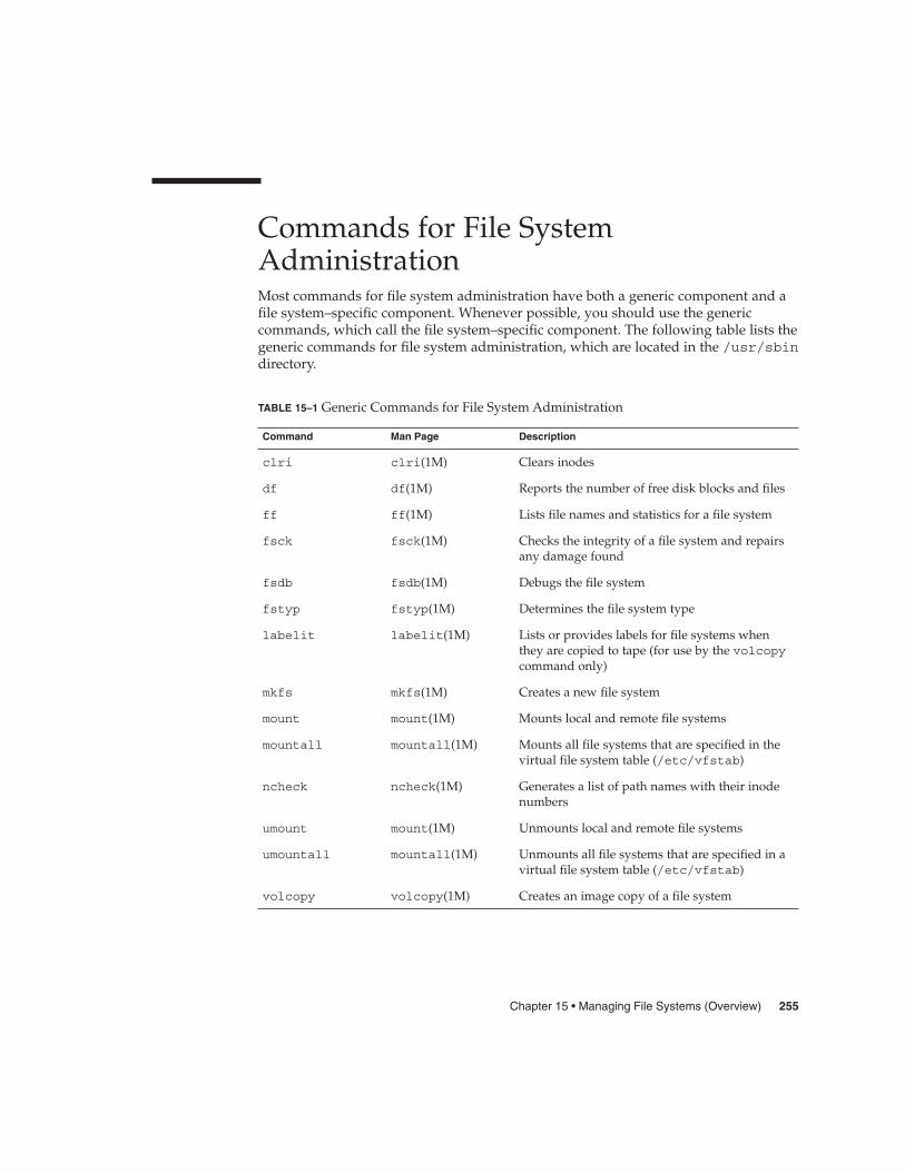
Commands for File SystemAdministrationMost commands for file system administration have both a generic component and afile system–specific component. Whenever possible, you should use the genericcommands, which call the file system–specific component. The following table lists thegeneric commands for file system administration, which are located in the /usr/sbindirectory.
TABLE 15–1 Generic Commands for File System Administration
Command Man Page Description
clri clri(1M) Clears inodes
df df(1M) Reports the number of free disk blocks and files
ff ff(1M) Lists file names and statistics for a file system
fsck fsck(1M) Checks the integrity of a file system and repairsany damage found
fsdb fsdb(1M) Debugs the file system
fstyp fstyp(1M) Determines the file system type
labelit labelit(1M) Lists or provides labels for file systems whenthey are copied to tape (for use by the volcopycommand only)
mkfs mkfs(1M) Creates a new file system
mount mount(1M) Mounts local and remote file systems
mountall mountall(1M) Mounts all file systems that are specified in thevirtual file system table (/etc/vfstab)
ncheck ncheck(1M) Generates a list of path names with their inodenumbers
umount mount(1M) Unmounts local and remote file systems
umountall mountall(1M) Unmounts all file systems that are specified in avirtual file system table (/etc/vfstab)
volcopy volcopy(1M) Creates an image copy of a file system
Chapter 15 • Managing File Systems (Overview) 255

How File System Commands Determine the FileSystem TypeThe generic file system commands determine the file system type by following thissequence:
1. From the -F option, if supplied.
2. By matching a special device with an entry in the /etc/vfstab file (if special issupplied). For example, fsck first looks for a match against the fsck devicefield. If no match is found, it then checks the special device field.
3. By using the default specified in the /etc/default/fs file for local file systemsand in the /etc/dfs/fstypes file for remote file systems.
Manual Pages for Generic and Specific CommandsBoth the generic commands and specific commands have manual pages in the manpages section 1M: System Administration Commands. The manual page for the generic filesystem commands provide information about generic command options only. Themanual page for a specific file system command has specific information aboutoptions for that file system. To look at a specific manual page, append an underscoreand the abbreviation for the file system type to the generic command name. Forexample, to see the specific manual page for mounting a UFS file system, type thefollowing:
$ man mount_ufs
The Default Solaris File SystemsThe Solaris UFS file system is hierarchical, starting with the root directory (/) andcontinuing downwards through a number of directories. The Solaris installationprocess enables you to install a default set of directories and uses a set of conventionsto group similar types of files together. The following table provides a summary of thedefault Solaris file systems.
256 System Administration Guide: Devices and File Systems • September 2004

TABLE 15–2 The Default Solaris File Systems
File System orDirectory File System Type Description
root (/) UFS The top of the hierarchical file tree. The root directorycontains the directories and files that are critical forsystem operation, such as the kernel, the device drivers,and the programs used to boot the system. The rootdirectory also contains the mount point directorieswhere local and remote file systems can be attached tothe file tree.
/usr UFS System files and directories that can be shared withother users. Files that run only on certain types ofsystems are in the /usr file system (for example,SPARC executables). Files that can be used on all typesof systems, such as the man pages, are in the/usr/share directory.
/export/home or/home
NFS, UFS The mount point for users’ home directories, whichstore user work files. By default the /home directory isan automounted file system. On standalone systems,the /home directory might be a UFS file system on alocal disk slice.
/var UFS System files and directories that are likely to change orgrow over the life of the local system. These includesystem logs, vi and ex backup files, and uucp files.
/opt NFS, UFS Optional mount point for third-party software. Onsome systems, the /opt directory might be a UFS filesystem on a local disk slice.
/tmp TMPFS Temporary files, which are cleared each time the systemis booted or the /tmp file system is unmounted.
/proc PROCFS A list of active processes, by number.
/etc/mnttab MNTFS A file system that provides read-only access to the tableof mounted file systems for the local system.
/var/run TMPFS A file system for storing temporary files that are notneeded after the system is booted.
The root (/) and /usr file systems are needed to run a system. Some of the most basiccommands in the /usr file system (like mount) are included in the root (/) file systemso that they are available when the system boots or is in single-user mode and /usr isnot mounted. For more detailed information on the default directories for the root (/)and /usr file systems, see Chapter 21.
Chapter 15 • Managing File Systems (Overview) 257

Swap SpaceThe Solaris operating system uses some disk slices for temporary storage rather thanfor file systems. These slices are called swap slices, or swap space. Swap space is used asvirtual memory storage areas when the system does not have enough physicalmemory to handle current processes.
Since many applications rely on swap space, you should know how to plan for,monitor, and add more swap space when needed. For an overview about swap spaceand instructions for adding swap space, see Chapter 19.
The UFS File SystemUFS is the default disk-based file system in Solaris operating system. Most often, whenyou administer a disk-based file system, you will be administering UFS file systems.UFS provides the following features:
UFS Feature Description
State flags Show the state of the file system: clean, stable, active,logging, or unknown. These flags eliminate unnecessaryfile system checks. If the file system is “clean,” “stable,” or“logging,” file system checks are not run.
Extended fundamental types(EFT)
Provides 32-bit user ID (UID), group ID (GID), and devicenumbers.
Large file systems Allows files of approximately 1 terabyte in size in a filesystem that can be up to 16 terabytes in size. You can createa multiterabyte UFS file system on a disk with an EFI disklabel.
For detailed information about the UFS file system structure, see Chapter 21.
Planning UFS File SystemsWhen laying out file systems, you need to consider possible conflicting demands. Hereare some suggestions:
258 System Administration Guide: Devices and File Systems • September 2004

� Distribute the work load as evenly as possible among different I/O systems anddisk drives. Distribute the /export/home file system and swap space evenlyacross disks.
� Keep pieces of projects or members of groups within the same file system.� Use as few file systems per disk as possible. On the system (or boot) disk, you
should have three file systems: root (/), /usr, and swap space. On other disks,create one or, at most, two file systems; one being additional swap space,preferably. Fewer, roomier file systems cause less file fragmentation than manysmall, over-crowded file systems. Higher-capacity tape drives and the ability of theufsdump command to handle multiple volumes make it easier to back up largerfile systems.
� If you have some users who consistently create very small files, consider creating aseparate file system with more inodes. However, most sites do not need to keepsimilar types of user files in the same file system.
For information on default file system parameters as well as procedures for creatingnew UFS file systems, see Chapter 16.
UFS LoggingUFS logging bundles the multiple metadata changes that make up a complete UFSoperation into a transaction. Sets of transactions are recorded in an on-disk log, andthen applied to the actual UFS file system’s metadata.
At reboot, the system discards incomplete transactions, but applies the transactions forcompleted operations. The file system remains consistent because only completedtransactions are ever applied. This consistency remains even when a system crashes,which normally interrupts system calls and introduces inconsistencies into a UFS filesystem.
UFS logging provides two advantages:
� If the file system is already consistent due to the transaction log, you might nothave to run the fsck command after a system crash or an unclean shutdown. Formore information on unclean shutdowns, see “What the fsck Command Checksand Tries to Repair” on page 333.
� Starting in the Solaris 9 12/02 release, the performance of UFS logging improves orexceeds the level of performance of non-logging file systems. This improvementcan occur because a file system with logging enabled converts multiple updates tothe same data into single updates, and so reduces the number of overhead diskoperations required.
The log is allocated from free blocks on the file system, and it is sized at approximately1 Mbyte per 1 Gbyte of file system, up to a maximum of 64 Mbytes. The log iscontinually flushed as it fills up. The log is also flushed when the file system isunmounted or as a result of any lockfs command.
Chapter 15 • Managing File Systems (Overview) 259
UFS logging is enabled by default for all UFS file systems.
If you need to disable UFS logging, add the nologging option to the file system’s entryin the /etc/vfstab file or when you mount the file system manually.
If you need to enable UFS logging, specify the -o logging option with the mountcommand in the /etc/vfstab file or when you mount the file system manually.Logging can be enabled on any UFS file system, including the root (/) file system.Also, the fsdb command now has new debugging commands to support UFSlogging.
In some operating systems, a file system with logging enabled is known as a journalingfile system.
UFS SnapshotsYou can use the fssnap command to create a read-only snapshot of a file system. Asnapshot is a file system’s temporary image that is intended for backup operations.
See Chapter 24 for more information.
UFS Direct Input/Output (I/O)Direct I/O is intended to boost bulk I/O operations. Bulk I/O operations use largebuffer sizes to transfer large files (larger than 256 Kbytes).
Using UFS direct I/O might benefit applications, such as database engines, that dotheir own internal buffering. Starting with the Solaris 8 1/01 release, UFS direct I/Ohas been enhanced to allow the same kind of I/O concurrency seen when accessingraw devices. Now you can get the benefit of file system naming and flexibility withvery little performance penalty. Check with your database vendor to see if they canenable UFS direct I/O in their product configuration options.
Direct I/O can also be enabled on a file system by using the forcedirectio optionto the mount command. Enabling direct I/O is a performance benefit only when a filesystem is transferring large amounts of sequential data.
When a file system is mounted with this option, data is transferred directly between auser’s address space and the disk. When forced direct I/O is not enabled for a filesystem, data transferred between a user’s address space and the disk is first bufferedin the kernel address space.
The default behavior is no forced direct I/O on a UFS file system. For moreinformation, see mount_ufs(1M).
260 System Administration Guide: Devices and File Systems • September 2004

Mounting and Unmounting File SystemsBefore you can access the files on a file system, you need to mount the file system.When you mount a file system, you attach that file system to a directory (mount point)and make it available to the system. The root (/) file system is always mounted. Anyother file system can be connected or disconnected from the root (/) file system.
When you mount a file system, any files or directories in the underlying mount pointdirectory are unavailable as long as the file system is mounted. These files are notpermanently affected by the mounting process, and they become available again whenthe file system is unmounted. However, mount directories are typically empty,because you usually do not want to obscure existing files.
For example, the following figure shows a local file system, starting with a root (/) filesystem and the sbin, etc, and opt subdirectories.
SUNWrtvc
/
etc optsbin
optfs
ufs
mount
rc0
shutdown mount
group
system
ttydefs
FIGURE 15–1 Sample root (/) File System
To access a local file system from the /opt file system that contains a set of unbundledproducts, you must do the following:
� First, you must create a directory to use as a mount point for the file system youwant to mount, for example, /opt/unbundled.
� Once the mount point is created, you can mount the file system (by using themount command), which makes all of the files and directories in/opt/unbundled available, as shown in the following figure.
Chapter 15 • Managing File Systems (Overview) 261

For step-by-step instructions on how to mount file systems, see Chapter 17.
/
etcsbin
optfs
opt
SUNWrtvc unbundled
app2app1ufs
mount
rc0
shutdown mount
group
system
ttydefs
file1
file2
file3
file1
file2
file3
Mount point
File system
FIGURE 15–2 Mounting a File System
The Mounted File System TableWhenever you mount or unmount a file system, the /etc/mnttab (mount table) fileis modified with the list of currently mounted file systems. You can display thecontents of this file with the cat or more commands, but you cannot edit it. Here is anexample of an /etc/mnttab file:
$ more /etc/mnttab/dev/dsk/c0t0d0s0 / ufs rw,intr,largefiles,onerror=panic,suid,dev=2200000 938557523/proc /proc proc dev=3180000 938557522fd /dev/fd fd rw,suid,dev=3240000 938557524mnttab /etc/mnttab mntfs dev=3340000 938557526swap /var/run tmpfs dev=1 938557526swap /tmp tmpfs dev=2 938557529/dev/dsk/c0t0d0s7 /export/home ufs rw,intr,largefiles,onerror=panic,suid,dev=2200007 ...
$
262 System Administration Guide: Devices and File Systems • September 2004

The Virtual File System TableIt would be a very time-consuming and error-prone task to manually mount filesystems every time you wanted to access them. To avoid this problem, the virtual filesystem table (the /etc/vfstab file) provides a list of file systems and how to mountthem.
The /etc/vfstab file provides two important features:
� You can specify file systems to automatically mount when the system boots.
� You can mount file systems by using only the mount point name, because the/etc/vfstab file contains the mapping between the mount point and the actualdevice slice name.
A default /etc/vfstab file is created when you install a system, depending on theselections you make when installing system software. However, you can edit the/etc/vfstab file on a system whenever you want. To add an entry, the maininformation you need to specify is the device where the file system resides, the nameof the mount point, the type of the file system, whether you want the file system tomount automatically when the system boots (by using the mountall command), andany mount options.
The following is an example of an /etc/vfstab file. Comment lines begin with #.This example shows an /etc/vfstab file for a system with two disks (c0t0d0 andc0t3d0).
$ more /etc/vfstab#device device mount FS fsck mount mount#to mount to fsck point type pass at boot options/dev/dsk/c0t0d0s0 /dev/rdsk/c0t0d0s0 / ufs 1 no -/proc - /proc proc - no -/dev/dsk/c0t0d0s1 - - swap - no -swap - /tmp tmpfs - yes -/dev/dsk/c0t0d0s6 /dev/rdsk/c0t0d0s6 /usr ufs 2 no -/dev/dsk/c0t3d0s7 /dev/rdsk/c0t3d0s7 /test ufs 2 yes -
$
In the preceding example, the last entry specifies that a UFS file system on the/dev/dsk/c0t3d0s7 slice will be automatically mounted on the /test mount pointwhen the system boots. Note that, for root (/) and /usr, the mount at boot fieldvalue is specified as no, because these file systems are mounted by the kernel as partof the boot sequence before the mountall command is run.
For descriptions of each of the /etc/vfstab fields and information on how to editand use the file, see Chapter 17.
Chapter 15 • Managing File Systems (Overview) 263

The NFS EnvironmentNFS is a distributed file system service that can be used to share resources (files ordirectories) from one system, typically a server, with other systems on the network.For example, you might want to share third-party applications or source files withusers on other systems.
NFS makes the actual physical location of the resource irrelevant to the user. Instead ofplacing copies of commonly used files on every system, NFS allows you to place onecopy on one system’s disk and let all other systems access it from the network. UnderNFS, remote files are virtually indistinguishable from local ones.
A system becomes an NFS server if it has resources to share on the network. A serverkeeps a list of currently shared resources and their access restrictions (such asread/write or read-only access).
When you share a resource, you make it available for mounting by remote systems.
You can share a resource in these ways:
� By using the share or shareall command
� By adding an entry to the /etc/dfs/dfstab (distributed file system table) fileand rebooting the system
For information on how to share resources, see Chapter 17. For a complete descriptionof NFS, see Chapter 14, “Managing Network File Systems (Overview),” in SystemAdministration Guide: Resource Management and Network Services.
Automounting or AutoFSYou can mount NFS file system resources by using a client-side service calledautomounting (or AutoFS), which enables a system to automatically mount andunmount NFS resources whenever you access them. The resource remains mounted aslong as you remain in the directory and are using a file. If the resource is not accessedfor a certain period of time, it is automatically unmounted.
AutoFS provides the following features:
� NFS resources don’t need to be mounted when the system boots, which savesbooting time.
� Users don’t need to know the root password to mount and unmount NFSresources.
� Network traffic might be reduced, since NFS resources are only mounted whenthey are in use.
264 System Administration Guide: Devices and File Systems • September 2004

The AutoFS service is initialized by the automount utility, which runs automaticallywhen a system is booted. The automountd daemon runs continuously and isresponsible for the mounting and unmounting of the NFS file systems on anas-needed basis. By default, the /home file system is is mounted by the automountdaemon.
With AutoFS, you can specify multiple servers to provide the same file system. Thisway, if one of the servers is down, AutoFS can try to mount from another machine.
For complete information on how to set up and administer AutoFS, see SystemAdministration Guide: IP Services.
Determining a File System’s TypeYou can determine a file system’s type by using the following:
� The FS type field in the virtual file system table (/etc/vfstab file)� The /etc/default/fs file for local file systems� The /etc/dfs/fstypes file for NFS file systems
How to Determine a File System’s TypeThis procedure works whether the file system is mounted or not.
Determine a file system’s type by using the grep command.
$ grep mount-point fs-table
mount-point Specifies the mount point name of the file system for which you wantto know the file system type. For example, the /var directory.
fs-table Specifies the absolute path to the file system table in which to searchfor the file system’s type. If the file system is mounted, fs-table shouldbe /etc/mnttab. If the file system isn’t mounted, fs-table should be/etc/vfstab.
Information for the mount point is displayed.
Note – If you have the raw device name of a disk slice, you can use the fstypcommand to determine a file system’s type (if the disk slice contains a file system). Formore information, see fstyp(1M).
Chapter 15 • Managing File Systems (Overview) 265
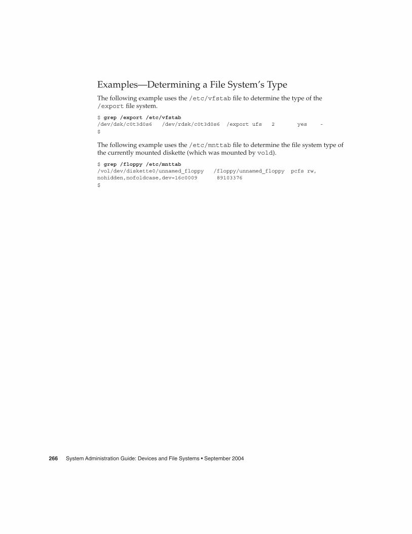
Examples—Determining a File System’s TypeThe following example uses the /etc/vfstab file to determine the type of the/export file system.
$ grep /export /etc/vfstab/dev/dsk/c0t3d0s6 /dev/rdsk/c0t3d0s6 /export ufs 2 yes -
$
The following example uses the /etc/mnttab file to determine the file system type ofthe currently mounted diskette (which was mounted by vold).
$ grep /floppy /etc/mnttab/vol/dev/diskette0/unnamed_floppy /floppy/unnamed_floppy pcfs rw,nohidden,nofoldcase,dev=16c0009 89103376
$
266 System Administration Guide: Devices and File Systems • September 2004

CHAPTER 16
Creating UFS, TMPFS, and LOFS FileSystems (Tasks)
This chapter describes how to create UFS, temporary (TMPFS), and loopback (LOFS)file systems. For UFS file systems, this chapter shows you how to create a file systemon a hard disk by using the newfs command. Because TMPFS and LOFS are virtualfile systems, you actually “access” them by mounting them.
This is a list of the step-by-step instructions in this chapter.
� “How to Create a UFS File System” on page 268� “How to Create a TMPFS File System” on page 270� “How to Create an LOFS File System” on page 272
Note – For instructions on how to create UFS and DOS file systems on removablemedia, see Chapter 1.
Creating a UFS File SystemBefore you can create a UFS file system on a disk, the disk must be formatted anddivided into slices. A disk slice is a physical subset of a disk that is composed of asingle range of contiguous blocks. A slice can be used either as a raw device thatprovides, for example, swap space, or to hold a disk-based file system. See Chapter 10for complete information on formatting disks and dividing disks into slices.
Volume management products, like Solaris Volume Manager, create moresophisticated volumes, that expand beyond single slice or single disk boundaries. Formore information about using volumes, see Solaris Volume Manager AdministrationGuide.
267

Note – Solaris device names use the term slice (and the letter s in the device name) torefer to the slice number. Slices are also called “partitions.”
You need to create UFS file systems only occasionally, because the Solaris operatingsystem automatically creates them as part of the installation process. You need tocreate (or re-create) a UFS file system when you want to do the following:
� Add or replace disks� Change the existing partitioning structure� Do a full restoration of a file system
The newfs command is the standard way to create UFS file systems. The newfscommand is a convenient front-end to the mkfs command, which actually creates thenew file system. The newfs command reads parameter defaults, such as tracks percylinder and sectors per track, from the disk label that will contain the new filesystem. The options you choose are passed to the mkfs command to build the filesystem.
Default Parameters for the newfs CommandTo make a new file system on a disk slice, you almost always use the newfscommand. The following table shows the default parameters that are used by thenewfs command.
Parameter Default Value
Block size 8 Kbytes
Fragment size 1 Kbyte
Minimum free space ((64 Mbytes/partition size) * 100), rounded down to thenearest integer and limited to between 1% and 10%,inclusively
Rotational delay Zero
Optimization type Time
Number of inodes 1 inode for each 2 Kbytes of data space
� How to Create a UFS File System
1. Make sure you have met the following prerequisites:
a. The disk must be formatted and divided into slices.
Steps
268 System Administration Guide: Devices and File Systems • September 2004

For information on formatting disks and dividing disks into slices, seeChapter 10.
b. You need to know the device name of the slice that will contain the filesystem.
For information on finding disks and disk slice numbers, see Chapter 11.
c. If you are re-creating an existing UFS file system, unmount it.
d. You must be superuser or assume an equivalent role.
2. Create the UFS file system.
# newfs [-N] [-b size] [-i bytes] /dev/rdsk/device-name
-N Displays what parameters the newfs command would pass to themkfs command without actually creating the file system. Thisoption is a good way to test the newfs command.
-b size Specifies the block size for the file system, either 4096 or 8192 bytesper block. The default is 8192.
-i bytes Specifies the number of bytes per inode. The default variesdepending on the disk size. For more information, see newfs(1M).
device-name Specifies the disk device name on which to create the new filesystem.
The system asks for confirmation.
Caution – Be sure you have specified the correct device name for the slice beforeperforming this step. If you specify the wrong slice, you will erase its contentswhen the new file system is created. This error might cause the system to panic.
3. To verify the creation of the UFS file system, check the new file system.
# fsck /dev/rdsk/device-name
The device-name argument specifies the name of the disk device that contains thenew file system.
The fsck command checks the consistency of the new file system, reports anyproblems, and prompts you before it repairs the problems. For more informationon the fsck command, see Chapter 20 or fsck(1M).
Creating a UFS File System
The following example shows how to create a UFS file system on/dev/rdsk/c0t1d0s7.
Example 16–1
Chapter 16 • Creating UFS, TMPFS, and LOFS File Systems (Tasks) 269
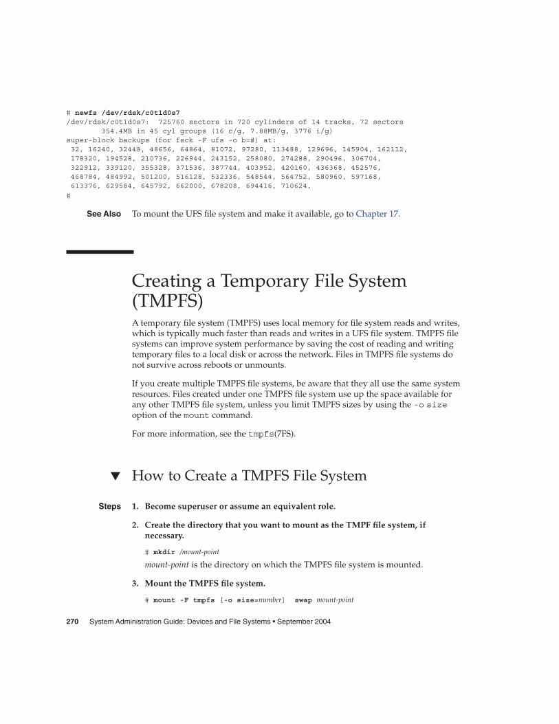
# newfs /dev/rdsk/c0t1d0s7/dev/rdsk/c0t1d0s7: 725760 sectors in 720 cylinders of 14 tracks, 72 sectors
354.4MB in 45 cyl groups (16 c/g, 7.88MB/g, 3776 i/g)super-block backups (for fsck -F ufs -o b=#) at:32, 16240, 32448, 48656, 64864, 81072, 97280, 113488, 129696, 145904, 162112,178320, 194528, 210736, 226944, 243152, 258080, 274288, 290496, 306704,322912, 339120, 355328, 371536, 387744, 403952, 420160, 436368, 452576,468784, 484992, 501200, 516128, 532336, 548544, 564752, 580960, 597168,613376, 629584, 645792, 662000, 678208, 694416, 710624,
#
To mount the UFS file system and make it available, go to Chapter 17.
Creating a Temporary File System(TMPFS)A temporary file system (TMPFS) uses local memory for file system reads and writes,which is typically much faster than reads and writes in a UFS file system. TMPFS filesystems can improve system performance by saving the cost of reading and writingtemporary files to a local disk or across the network. Files in TMPFS file systems donot survive across reboots or unmounts.
If you create multiple TMPFS file systems, be aware that they all use the same systemresources. Files created under one TMPFS file system use up the space available forany other TMPFS file system, unless you limit TMPFS sizes by using the -o sizeoption of the mount command.
For more information, see the tmpfs(7FS).
� How to Create a TMPFS File System
1. Become superuser or assume an equivalent role.
2. Create the directory that you want to mount as the TMPF file system, ifnecessary.
# mkdir /mount-point
mount-point is the directory on which the TMPFS file system is mounted.
3. Mount the TMPFS file system.
# mount -F tmpfs [-o size=number] swap mount-point
See Also
Steps
270 System Administration Guide: Devices and File Systems • September 2004
-o size=number Specifies the size limit of the TMPFS file system in Mbytes.
mount-point Specifies the directory on which the TMPFS file system ismounted.
To set up the system to automatically mount a TMPFS file system when it boots,see Example 16–3.
4. Verify that the TMPFS file system has been created.
# mount -v
Creating a TMPFS File System
The following example shows how to create, mount, and limit the size of the TMPFSfile system, /export/reports, to 50 Mbytes.
# mkdir /export/reports# chmod 777 /export/reports
# mount -F tmpfs -o size=50m swap /export/reports
Mounting a TMPFS File System at Boot Time
You can set up the system to automatically mount a TMPFS file system when it bootsby adding an /etc/vfstab entry. The following example shows an entry in the/etc/vfstab file that mounts /export/test as a TMPFS file system when thesystem boots. Since the size=number option is not specified, the size of the TMPFS filesystem on /export/test is limited only by the available system resources.
swap - /export/test tmpfs - yes -
For more information on the /etc/vfstab file, see “Field Descriptions for the/etc/vfstab File” on page 278.
Creating a Loopback File System (LOFS)A LOFS file system is a virtual file system that provides an alternate path to anexisting file system. When other file systems are mounted onto an LOFS file system,the original file system does not change.
For more information, see the lofs(7FS).
Example 16–2
Example 16–3
Chapter 16 • Creating UFS, TMPFS, and LOFS File Systems (Tasks) 271
Caution – Be careful when creating LOFS file systems. Because LOFS file systems arevirtual file systems, the potential for confusing both users and applications isenormous.
� How to Create an LOFS File System
1. Become superuser or assume an equivalent role.
2. Create the directory you want to mount as an LOFS file system, if necessary.
# mkdir loopback-directory
3. Grant the appropriate permissions and ownership on the newly createddirectory.
4. Create the mount point where you want to mount the LOFS file system, ifnecessary.
# mkdir /mount-point
5. Mount the LOFS file system.
# mount -F lofs loopback-directory /mount-point
loopback-directory Specifies the file system to be mounted on the loopback mountpoint.
/mount-point Specifies the directory on which to mount the LOFS filesystem.
6. Verify that the LOFS file system has been mounted.
# mount -v
Creating and Mounting an LOFS File System
The following example illustrates how to create, mount, and test new software in the/new/dist directory as a loopback file system without actually having to install it.
# mkdir /tmp/newroot# mount -F lofs /new/dist /tmp/newroot
# chroot /tmp/newroot newcommand
Steps
Example 16–4
272 System Administration Guide: Devices and File Systems • September 2004
Mounting an LOFS File System at Boot Time
You can set up the system to automatically mount an LOFS file system when it bootsby adding an entry to the end of the /etc/vfstab file. The following example showsan entry in the /etc/vfstab file that mounts an LOFS file system for the root (/) filesystem on /tmp/newroot.
/ - /tmp/newroot lofs - yes -
Make sure the loopback entries are the last entries in the /etc/vfstab file.Otherwise, if the /etc/vfstab entry for a loopback file system precedes the filesystems to be included in it, the loopback file system cannot be mounted.
For more information on the /etc/vfstab file, see “Field Descriptions for the/etc/vfstab File” on page 278.
Example 16–5
See Also
Chapter 16 • Creating UFS, TMPFS, and LOFS File Systems (Tasks) 273

274 System Administration Guide: Devices and File Systems • September 2004

CHAPTER 17
Mounting and Unmounting FileSystems (Tasks)
This chapter describes how to mount and unmount file systems.
This is a list of the step-by-step instructions in this chapter.
� “How to Determine Which File Systems Are Mounted” on page 280� “How to Add an Entry to the /etc/vfstab File” on page 281� “How to Mount a File System (/etc/vfstab File)” on page 282� “How to Mount a UFS File System (mount Command)” on page 283� “How to Mount a UFS File System Without Large Files (mount Command)”
on page 284� “How to Mount an NFS File System (mount Command)” on page 285� “x86: How to Mount a PCFS (DOS) File System From a Hard Disk (mount
Command)” on page 286� “How to Verify a File System is Unmounted” on page 288� “How to Stop All Processes Accessing a File System” on page 288� “How to Unmount a File System” on page 289
Overview of Mounting File SystemsAfter you create a file system, you need to make it available to the system so you canuse it. You make a file system available by mounting it, which attaches the file systemto the system directory tree at the specified mount point. The root (/) file system isalways mounted.
The following table provides guidelines on mounting file systems based on how youuse them.
275

Mount Type Needed Suggested Mount Method
Local or remote file systems that need to bemounted infrequently
The mount command that you enter manuallyfrom the command line.
Local file systems that need to be mountedfrequently
The /etc/vfstab file, which mounts the filesystem automatically when the system isbooted in multi-user state.
Remote file systems that need to be mountedfrequently, such as home directories
� The /etc/vfstab file, whichautomatically mounts the file system whenthe system is booted in multi-user state.
� AutoFS, which automatically mounts orunmounts the file system when you accessor change out of the directory.
To enhance performance, you can also cachethe remote file systems by using the CacheFSfile system.
You can mount media that contains a file system by inserting the media into the driveand running the volcheck command if necessary. For more information on mountingremovable media, see Chapter 1.
Commands for Mounting and Unmounting FileSystemsThe following table lists the commands in the /usr/sbin directory that you use tomount and unmount file systems.
TABLE 17–1 Commands for Mounting and Unmounting File Systems
Command Man Page Description
mount mount(1M) Mounts file systems and remote resources.
mountall mountall(1M) Mounts all file systems that are specified in the/etc/vfstab file. The mountall command runsautomatically when the system enters multiusermode.
umount mount(1M) Unmounts file systems and remote resources.
umountall mountall(1M) Unmounts all file systems that are specified in the/etc/vfstab file.
The mount and mountall commands will not mount a read/write file system thathas known inconsistencies. If you receive an error message from the mount ormountall command, you might need to check the file system. See Chapter 20 forinformation on how to check the file system.
276 System Administration Guide: Devices and File Systems • September 2004

The umount and umountall commands will not unmount a file system that is busy.A file system is considered busy if one of the following is true:
� A user is accessing a file or directory in the file system.� If a program has a file open in that file system.� If the file system is shared.
Commonly Used Mount OptionsThe following table describes the commonly used options that you can specify withthe mount -o option. If you specify multiple options, separate them with commas (nospaces). For example, -o ro,nosuid.
For a complete list of mount options for each file system type, refer to the specificmount man pages (for example, mount_ufs(1M)).
TABLE 17–2 Commonly Used -o Mount Options
Option File System Description
bg | fg NFS If the first mount attempt fails, retries in thebackground (bg) or in the foreground (fg). Thisoption is safe for non-critical vfstab entries.The default is fg.
hard | soft NFS Specifies the procedure if the server does notrespond. The soft option indicates that an erroris returned. The hard option indicates that theretry request is continued until the serverresponds. The default is hard.
intr | nointr NFS Specifies whether keyboard interrupts aredelivered to a process that is hung while waitingfor a response on a hard-mounted file system.The default is intr (interrupts allowed).
largefiles |nolargefiles
UFS Enables you to create files larger than 2 Gbytes.The largefiles option means that a filesystem mounted with this option might containfiles larger than 2 Gbytes, but it is not required.If the nolargefiles option is specified, the filesystem cannot be mounted on a system that isrunning Solaris 2.6 or compatible versions. Thedefault is largefiles.
Chapter 17 • Mounting and Unmounting File Systems (Tasks) 277

TABLE 17–2 Commonly Used -o Mount Options (Continued)Option File System Description
logging |nologging
UFS Enables or disables logging for the file system.UFS logging is the process of storingtransactions (changes that make up a completeUFS operation) into a log before the transactionsare applied to the UFS file system. Logginghelps prevent UFS file systems from becominginconsistent, which means fsck can bebypassed. Bypassing fsck reduces the time toreboot a system if it crashes, or after a system isshutdown uncleanly.
The log is allocated from free blocks on the filesystem, and is sized at approximately 1 Mbyteper 1 Gbyte of file system, up to a maximum of64 Mbytes. The default is logging.
atime | noatime UFS Suppresses access time updates on files, exceptwhen they coincide with updates to the time ofthe last file status change or the time of the lastfile modification. For more information, seestat(2). This option reduces disk activity on filesystems where access times are unimportant (forexample, a Usenet news spool). The default isnormal access time (atime) recording.
remount All Changes the mount options associated with analready-mounted file system. This option cangenerally be used with any option except ro,but what can be changed with this option isdependent on the file system type.
retry=n NFS Retries the mount operation when it fails. n isthe number of times to retry.
ro | rw CacheFS, NFS,PCFS, UFS, HSFS
Specifies read/write (rw) or read-only (ro). Ifyou do not specify this option, the default is rw.The default option for HSFS is ro.
suid | nosuid CacheFS, HSFS,NFS, UFS
Allows or disallows setuid execution. Thedefault is to allow setuid execution.
Field Descriptions for the /etc/vfstab FileAn entry in the /etc/vfstab file has seven fields, which are described in thefollowing table.
278 System Administration Guide: Devices and File Systems • September 2004
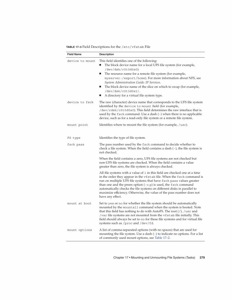
TABLE 17–3 Field Descriptions for the /etc/vfstab File
Field Name Description
device to mount This field identifies one of the following:� The block device name for a local UFS file system (for example,
/dev/dsk/c0t0d0s0).� The resource name for a remote file system (for example,
myserver:/export/home). For more information about NFS, seeSystem Administration Guide: IP Services.
� The block device name of the slice on which to swap (for example,/dev/dsk/c0t3d0s1).
� A directory for a virtual file system type.
device to fsck The raw (character) device name that corresponds to the UFS file systemidentified by the device to mount field (for example,/dev/rdsk/c0t0d0s0). This field determines the raw interface that isused by the fsck command. Use a dash (-) when there is no applicabledevice, such as for a read-only file system or a remote file system.
mount point Identifies where to mount the file system (for example, /usr).
FS type Identifies the type of file system.
fsck pass The pass number used by the fsck command to decide whether tocheck a file system. When the field contains a dash (-), the file system isnot checked.
When the field contains a zero, UFS file systems are not checked butnon-UFS file systems are checked. When the field contains a valuegreater than zero, the file system is always checked.
All file systems with a value of 1 in this field are checked one at a timein the order they appear in the vfstab file. When the fsck command isrun on multiple UFS file systems that have fsck pass values greaterthan one and the preen option (-o p) is used, the fsck commandautomatically checks the file systems on different disks in parallel tomaximize efficiency. Otherwise, the value of the pass number does nothave any effect.
mount at boot Set to yes or no for whether the file system should be automaticallymounted by the mountall command when the system is booted. Notethat this field has nothing to do with AutoFS. The root (/), /usr and/var file systems are not mounted from the vfstab file initially. Thisfield should always be set to no for these file systems and for virtual filesystems such as /proc and /dev/fd.
mount options A list of comma-separated options (with no spaces) that are used formounting the file system. Use a dash (-) to indicate no options. For a listof commonly used mount options, see Table 17–2.
Chapter 17 • Mounting and Unmounting File Systems (Tasks) 279
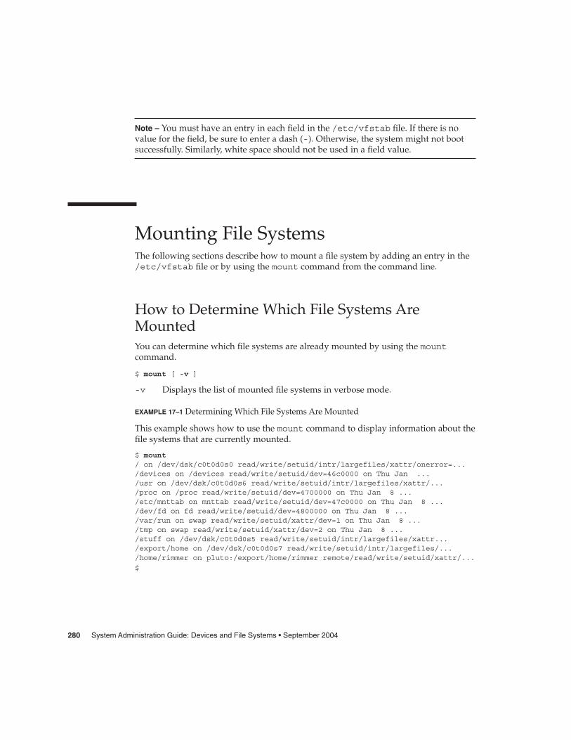
Note – You must have an entry in each field in the /etc/vfstab file. If there is novalue for the field, be sure to enter a dash (-). Otherwise, the system might not bootsuccessfully. Similarly, white space should not be used in a field value.
Mounting File SystemsThe following sections describe how to mount a file system by adding an entry in the/etc/vfstab file or by using the mount command from the command line.
How to Determine Which File Systems AreMountedYou can determine which file systems are already mounted by using the mountcommand.
$ mount [ -v ]
-v Displays the list of mounted file systems in verbose mode.
EXAMPLE 17–1 Determining Which File Systems Are Mounted
This example shows how to use the mount command to display information about thefile systems that are currently mounted.
$ mount/ on /dev/dsk/c0t0d0s0 read/write/setuid/intr/largefiles/xattr/onerror=.../devices on /devices read/write/setuid/dev=46c0000 on Thu Jan .../usr on /dev/dsk/c0t0d0s6 read/write/setuid/intr/largefiles/xattr/.../proc on /proc read/write/setuid/dev=4700000 on Thu Jan 8 .../etc/mnttab on mnttab read/write/setuid/dev=47c0000 on Thu Jan 8 .../dev/fd on fd read/write/setuid/dev=4800000 on Thu Jan 8 .../var/run on swap read/write/setuid/xattr/dev=1 on Thu Jan 8 .../tmp on swap read/write/setuid/xattr/dev=2 on Thu Jan 8 .../stuff on /dev/dsk/c0t0d0s5 read/write/setuid/intr/largefiles/xattr.../export/home on /dev/dsk/c0t0d0s7 read/write/setuid/intr/largefiles/.../home/rimmer on pluto:/export/home/rimmer remote/read/write/setuid/xattr/...
$
280 System Administration Guide: Devices and File Systems • September 2004

� How to Add an Entry to the /etc/vfstab File
1. Become superuser or assume an equivalent role.
2. Create a mount point for the file system to be mounted, if necessary.
# mkdir /mount-point
There must be a mount point on the local system to mount a file system. A mountpoint is a directory to which the mounted file system is attached.
3. Edit the /etc/vfstab file and add an entry. Make sure that you do thefollowing:
a. Separate each field with white space (a space or a tab).
b. Enter a dash (-) if a field has no contents.
c. Save the changes.
For detailed information about the /etc/vfstab field entries, see Table 17–3.
Note – Since the root (/) file system is mounted read-only by the kernel during theboot process, only the remount option (and options that can be used inconjunction with remount) affect the root (/) entry in the /etc/vfstab file.
Adding an Entry to the /etc/vfstab File
The following example shows how to mount the disk slice /dev/dsk/c0t3d0s7 as aUFS file system to the mount point directory /files1. The raw character device/dev/rdsk/c0t3d0s7 is specified as the device to fsck. The fsck pass valueof 2 means that the file system will be checked, but not sequentially.
#device device mount FS fsck mount mount#to mount to fsck point type pass at boot options#
/dev/dsk/c0t3d0s7 /dev/rdsk/c0t3d0s7 /files1 ufs 2 yes -
The following example shows how to mount the /export/man directory from thesystem pluto as an NFS file system on mount point /usr/man. A device to fscknor a fsck pass is specified because it’s an NFS file system. In this example, mountoptions are ro (read-only) and soft.
#device device mount FS fsck mount mount#to mount to fsck point type pass at boot options
pluto:/export/man - /usr/man nfs - yes ro,soft
Steps
Example 17–2
Chapter 17 • Mounting and Unmounting File Systems (Tasks) 281
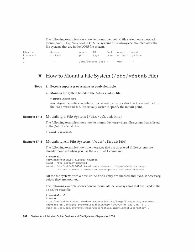
The following example shows how to mount the root (/) file system on a loopbackmount point, /tmp/newroot. LOFS file systems must always be mounted after thefile systems that are in the LOFS file system.
#device device mount FS fsck mount mount#to mount to fsck point type pass at boot options#/ - /tmp/newroot lofs - yes -
� How to Mount a File System (/etc/vfstab File)
1. Become superuser or assume an equivalent role.
2. Mount a file system listed in the /etc/vfstab file.
# mount /mount-point
/mount-point specifies an entry in the mount point or device to mount field inthe /etc/vfstab file. It is usually easier to specify the mount point.
Mounting a File System (/etc/vfstab File)
The following example shows how to mount the /usr/dist file system that is listedin the /etc/vfstab file.
# mount /usr/dist
Mounting All File Systems (/etc/vfstab File)
The following example shows the messages that are displayed if file systems arealready mounted when you use the mountall command.
# mountall/dev/rdsk/c0t0d0s7 already mountedmount: /tmp already mountedmount: /dev/dsk/c0t0d0s7 is already mounted, /export/home is busy,
or the allowable number of mount points has been exceeded
All the file systems with a device to fsck entry are checked and fixed, if necessary,before they are mounted.
The following example shows how to mount all the local systems that are listed in the/etc/vfstab file.
# mountall -l# mount/ on /dev/dsk/c0t0d0s0 read/write/setuid/intr/largefiles/xattr/onerror=.../devices on /devices read/write/setuid/dev=46c0000 on Thu Jan 8 .../usr on /dev/dsk/c0t0d0s6 read/write/setuid/intr/largefiles/xattr/...
Steps
Example 17–3
Example 17–4
282 System Administration Guide: Devices and File Systems • September 2004

/proc on /proc read/write/setuid/dev=4700000 on Thu Jan 8 .../etc/mnttab on mnttab read/write/setuid/dev=47c0000 on Thu Jan 8 .../dev/fd on fd read/write/setuid/dev=4800000 on Thu Jan 8 09:38:30 2004/var/run on swap read/write/setuid/xattr/dev=1 on Thu Jan 8 .../tmp on swap read/write/setuid/xattr/dev=2 on Thu Jan 8 09:38:30 2004/stuff on /dev/dsk/c0t0d0s5 read/write/setuid/intr/largefiles/xattr...
/export/home on /dev/dsk/c0t0d0s7 read/write/setuid/intr/largefiles/...
The following example shows how to mount all of the remote file systems that arelisted in the /etc/vfstab file.
# mountall -r# mount/ on /dev/dsk/c0t0d0s0 read/write/setuid/intr/largefiles/xattr/onerror=.../devices on /devices read/write/setuid/dev=46c0000 on Thu Jan 8 .../usr on /dev/dsk/c0t0d0s6 read/write/setuid/intr/largefiles/xattr/.../proc on /proc read/write/setuid/dev=4700000 on Thu Jan 8 .../etc/mnttab on mnttab read/write/setuid/dev=47c0000 on Thu Jan 8 .../dev/fd on fd read/write/setuid/dev=4800000 on Thu Jan 8 .../var/run on swap read/write/setuid/xattr/dev=1 on Thu Jan 8 .../tmp on swap read/write/setuid/xattr/dev=2 on Thu Jan 8 09:38:30 2004/stuff on /dev/dsk/c0t0d0s5 read/write/setuid/intr/largefiles/xattr.../export/home on /dev/dsk/c0t0d0s7 read/write/setuid/intr/largefiles/...
/home/rimmer on pluto:/export/home/rimmer remote/read/write/setuid/xattr/...
� How to Mount a UFS File System (mountCommand)
1. Become superuser or assume an equivalent role.
2. Create a mount point for the file system to be mounted, if necessary.
# mkdir /mount-point
There must be a mount point on the local system to mount a file system. A mountpoint is a directory to which the mounted file system is attached.
3. Mount the UFS file system.
# mount [-o mount-options] /dev/dsk/device-name /mount-point
-o mount-options Specifies mount options that you can use to mount aUFS file system. For a list of options, see Table 17–2 ormount_ufs(1M).
/dev/dsk/device-name Specifies the disk device name for the slice thatcontains the file system (for example,/dev/dsk/c0t3d0s7). To get slice information for adisk, see “How to Display Disk Slice Information”on page 185.
Steps
Chapter 17 • Mounting and Unmounting File Systems (Tasks) 283

/mount-point Specifies the directory on which to mount the filesystem.
Mounting a UFS File System (mount Command)
The following example shows how to mount /dev/dsk/c0t3d0s7 on the /files1directory.
# mount /dev/dsk/c0t3d0s7 /files1
� How to Mount a UFS File System Without LargeFiles (mount Command)When you mount a file system, the largefiles option is selected by default, whichenables you to create files larger than 2 Gbytes. Once a file system contains large files,you cannot remount the file system with the nolargefiles option or mount it on asystem that is running Solaris 2.6 or compatible versions, until you remove any largefiles and run the fsck command to reset the state to nolargefiles.
This procedure assumes that the file system is in the /etc/vfstab file.
1. Become superuser or assume an equivalent role.
2. Create a mount point for the file system to be mounted, if necessary.
# mkdir /mount-point
There must be a mount point on the local system to mount a file system. A mountpoint is a directory to which the mounted file system is attached.
3. Make sure there are no large files in the file system.
# cd /mount-point# find . -xdev -size +20000000 -exec ls -l {} \;
/mount-point identifies the mount point of the file system you want to check forlarge files.
4. Remove or move any large files in this file system to another file system, ifnecessary.
5. Unmount the file system.
# umount /mount-point
6. Reset the file system state.
# fsck /mount-point
Example 17–5
Steps
284 System Administration Guide: Devices and File Systems • September 2004

7. Remount the file system with the nolargefiles option.
# mount -o nolargefiles /mount-point
Mounting a File System Without Large Files (mount Command)
The following example shows how to check the /datab file system and remount itwith the nolargefiles option.
# cd /datab# find . -xdev -size +20000000 -exec ls -l {} \;# umount /datab# fsck /datab
# mount -o nolargefiles /datab
� How to Mount an NFS File System (mountCommand)
1. Become superuser or assume an equivalent role.
2. Create a mount point for the file system to be mounted, if necessary.
# mkdir /mount-point
There must be a mount point on the local system to mount a file system. A mountpoint is a directory to which the mounted file system is attached.
3. Make sure the resource (file or directory) is available from a server.
To mount an NFS file system, the resource must be made available on the server byusing the share command. For information on how to share resources, see “Aboutthe NFS Service” in System Administration Guide: Resource Management and NetworkServices.
4. Mount the NFS file system.
# mount -F nfs [-o mount-options] server:/directory /mount-point
-o mount-options Specifies mount options that you can use to mount an NFS filesystem. See Table 17–2 for the list of commonly used mountoptions or mount_nfs(1M) for a complete list of options.
server:/directory Specifies the server’s host name that contains the sharedresource, and the path to the file or directory to mount.
/mount-point Specifies the directory on which to mount the file system.
Example 17–6
Steps
Chapter 17 • Mounting and Unmounting File Systems (Tasks) 285

Mounting an NFS File System (mount Command)
The following example shows how to mount the /export/packages directory on/mnt from the server pluto.
# mount -F nfs pluto:/export/packages /mnt
� x86: How to Mount a PCFS (DOS) File SystemFrom a Hard Disk (mount Command)Use the following procedure to mount a PCFS (DOS) file system from a hard disk.
1. Become superuser or assume an equivalent role.
2. Create a mount point for the file system to be mounted, if necessary.
# mkdir /mount-point
There must be a mount point on the local system to mount a file system. A mountpoint is a directory to which the mounted file system is attached.
3. Mount the PCFS file system.
# mount -F pcfs [-o rw | ro] /dev/dsk/device-name:logical-drive /mount-point
-o rw | ro Specifies that you can mount a PCFS file systemread/write (rw) or read-only (ro). If you do not specifythis option, the default is rw.
/dev/dsk/device-name Specifies the device name of the whole disk (forexample, /dev/dsk/c0t0d0p0).
logical-drive Specifies either the DOS logical drive letter (c throughz) or a drive number (1 through 24). Drive c isequivalent to drive 1 and represents the Primary DOSslice on the drive. All other letters or numbers representDOS logical drives within the Extended DOS slice.
/mount-point Specifies the directory on which to mount the filesystem.
Note that the device-name and logical-drive must be separated by a colon.
Example 17–7
Steps
286 System Administration Guide: Devices and File Systems • September 2004

x86: Mounting a PCFS (DOS) File System From a Hard Disk (mountCommand)
The following example shows how to mount the logical drive in the primary DOSslice on the /pcfs/c directory.
# mount -F pcfs /dev/dsk/c0t0d0p0:c /pcfs/c
The following example shows how to mount the first logical drive in the extendedDOS slice read-only on /mnt.
# mount -F pcfs -o ro /dev/dsk/c0t0d0p0:2 /mnt
Unmounting File SystemsThe unmounting of a file system removes it from the file system mount point, anddeletes the entry from the /etc/mnttab file. Some file system administration taskscannot be performed on mounted file systems. You should unmount a file systemwhen the following occurs:
� The file system is no longer needed or has been replaced by a file system thatcontains more current software.
� You need to check and repair the file system by using the fsck command. Formore information about the fsck command, see Chapter 20.
It is a good idea to unmount a file system before doing a complete backup. Formore information about doing backups, see Chapter 23.
Note – File systems are automatically unmounted as part of the system shutdownprocedure.
You can use the umount -f option to forcibly unmount a file system that is busy in anemergency situation. This practice is not recommended under normal circumstancesbecause the unmounting of a file system with open files could cause a loss of data.This option is only available for UFS and NFS file systems.
Prerequisites for Unmounting File SystemsThe prerequisites for unmounting file systems include the following:
� You must be superuser or assume an equivalent role.
Example 17–8
Chapter 17 • Mounting and Unmounting File Systems (Tasks) 287

� A file system must be available for unmounting. You cannot unmount a file systemthat is busy. A file system is considered busy if a user is accessing a directory in thefile system, if a program has a file open in that file system, or if it is being shared.You can make a file system available for unmounting by doing the following:
� Changing to a directory in a different file system.
� Logging out of the system.
� Using the fuser command to list all processes that are accessing the file systemand to stop them if necessary. For more details, see “How to Stop All ProcessesAccessing a File System” on page 288.
Notify users if you need to unmount a file system that they are using.
� Unsharing the file system. For information about unsharing a file system, seeunshare(1M).
How to Verify a File System is UnmountedTo verify that you unmounted a file system or a number of file systems, examine theoutput from the mount command.
$ mount | grep unmounted-file-system$
� How to Stop All Processes Accessing a File System
1. Become superuser or assume an equivalent role.
2. List all the processes that are accessing the file system so that you know whichprocesses you are going to stop.
# fuser -c [ -u ] /mount-point
-c Reports on files that are mount points for file systems and any fileswithin those mounted file systems.
-u Displays the user login name for each process ID.
/mount-point Specifies the name of the file system for which you want to stopprocesses.
3. Stop all processes that are accessing the file system.
# fuser -c -k /mount-point
A SIGKILL is sent to each process that is using the file system.
Steps
288 System Administration Guide: Devices and File Systems • September 2004
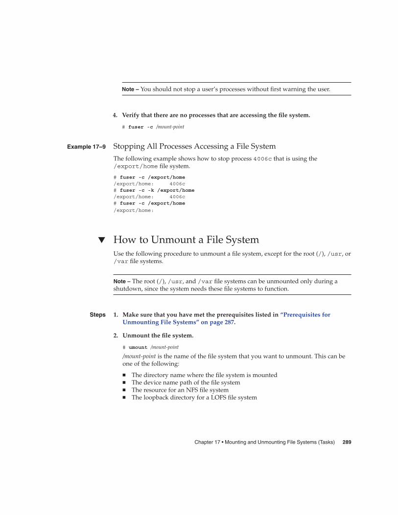
Note – You should not stop a user’s processes without first warning the user.
4. Verify that there are no processes that are accessing the file system.
# fuser -c /mount-point
Stopping All Processes Accessing a File System
The following example shows how to stop process 4006c that is using the/export/home file system.
# fuser -c /export/home/export/home: 4006c# fuser -c -k /export/home/export/home: 4006c# fuser -c /export/home
/export/home:
� How to Unmount a File SystemUse the following procedure to unmount a file system, except for the root (/), /usr, or/var file systems.
Note – The root (/), /usr, and /var file systems can be unmounted only during ashutdown, since the system needs these file systems to function.
1. Make sure that you have met the prerequisites listed in “Prerequisites forUnmounting File Systems” on page 287.
2. Unmount the file system.
# umount /mount-point
/mount-point is the name of the file system that you want to unmount. This can beone of the following:
� The directory name where the file system is mounted� The device name path of the file system� The resource for an NFS file system� The loopback directory for a LOFS file system
Example 17–9
Steps
Chapter 17 • Mounting and Unmounting File Systems (Tasks) 289

Unmounting a File System
The following example shows how to unmount a local home file system.
# umount /export/home
The following example shows how to unmount the file system on slice 7.
# umount /dev/dsk/c0t0d0s7
The following example shows how to forcibly unmount the /export file system.
# umount -f /export
#
The following example shows how to unmount all file systems in the /etc/vfstabfile, except for the root (/), /proc, /var, and /usr file systems.
# umountall
All file systems are unmounted, except for those file systems that are busy.
Example17–10
290 System Administration Guide: Devices and File Systems • September 2004

CHAPTER 18
Using The CacheFS File System (Tasks)
This chapter describes how to set up and maintain CacheFS™ file systems.
This is a list of task maps in this chapter.
� “High-Level View of Using the CacheFS File System (Task Map)” on page 291� “Creating and Mounting a CacheFS File System (Task Map)” on page 294� “Maintaining a CacheFS File System (Task Map)” on page 299� “Packing a Cached File System (Task Map)” on page 305� “Collecting CacheFS Statistics (Task Map)” on page 314
For information on troubleshooting CacheFS errors, see “Troubleshootingcachefspack Errors” on page 310.
High-Level View of Using the CacheFSFile System (Task Map)Use this task map to identify all the tasks for using CacheFS file systems. Each task inthis map points to a series of additional tasks such as creating and mounting theCacheFS file systems, and packing and maintaining the cache.
Task Description For Instructions
1. Create and mount aCacheFS file system
Create the cache and mountthe file system in the cache.
“Creating and Mounting aCacheFS File System (TaskMap)” on page 294
291

Task Description For Instructions
2. Maintain a CacheFS filesystem
Display and modify aCacheFS file system byunmounting, removing, orre-creating the cache.
“Maintaining a CacheFS FileSystem (Task Map)” on page299
3. (Optional) Pack and unpacka CacheFS file system
Determine whether you wantto pack the cache and usepacking lists. Packing thecache ensures that certain filesand directories are alwaysupdated in the cache.
“Packing a Cached FileSystem (Task Map)” on page305
4. Collect CacheFS statistics Determine cache performanceand appropriate cache size.
“Collecting CacheFS Statistics(Task Map)” on page 314
Overview of the CacheFS File SystemThe CacheFS file system is a general purpose caching mechanism that improves NFSserver performance and scalability by reducing server and network load. Designed asa layered file system, the CacheFS file system provides the ability to cache one filesystem on another. In an NFS environment, the CacheFS file system increases theclient per server ratio, reduces server and network loads, and improves performancefor clients on slow links, such as Point-to-Point Protocol (PPP).
How a CacheFS File System WorksYou create a CacheFS file system on a client system so that file systems you cache canbe accessed by the client locally instead of across the network. The following figureshows the relationship of the components that are involved in using CacheFS filesystem.
292 System Administration Guide: Devices and File Systems • September 2004
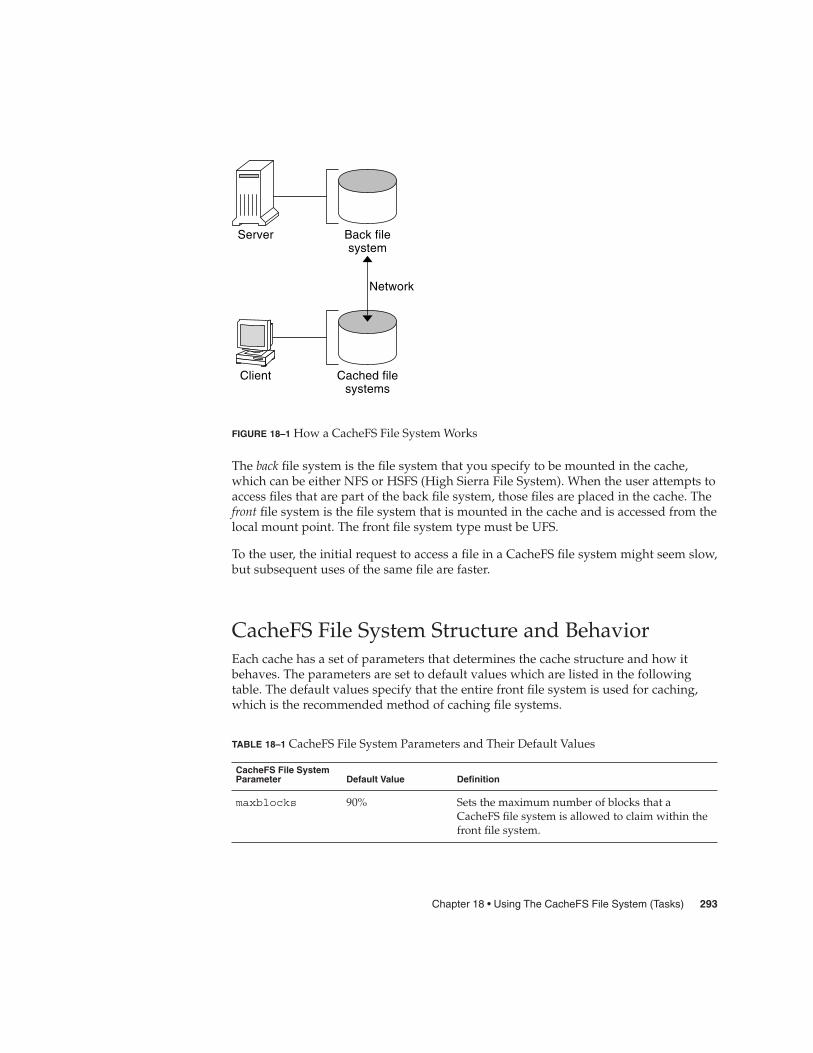
Back filesystem
Cached filesystems
Server
Client
Network
FIGURE 18–1 How a CacheFS File System Works
The back file system is the file system that you specify to be mounted in the cache,which can be either NFS or HSFS (High Sierra File System). When the user attempts toaccess files that are part of the back file system, those files are placed in the cache. Thefront file system is the file system that is mounted in the cache and is accessed from thelocal mount point. The front file system type must be UFS.
To the user, the initial request to access a file in a CacheFS file system might seem slow,but subsequent uses of the same file are faster.
CacheFS File System Structure and BehaviorEach cache has a set of parameters that determines the cache structure and how itbehaves. The parameters are set to default values which are listed in the followingtable. The default values specify that the entire front file system is used for caching,which is the recommended method of caching file systems.
TABLE 18–1 CacheFS File System Parameters and Their Default Values
CacheFS File SystemParameter Default Value Definition
maxblocks 90% Sets the maximum number of blocks that aCacheFS file system is allowed to claim within thefront file system.
Chapter 18 • Using The CacheFS File System (Tasks) 293

TABLE 18–1 CacheFS File System Parameters and Their Default Values (Continued)CacheFS File SystemParameter Default Value Definition
minblocks 0% Sets the minimum number of blocks that aCacheFS file system is allowed to claim within thefront file system.
threshblocks 85% Sets the number of blocks that must be available inthe front file system before a CacheFS file systemcan claim more than the blocks specified byminblocks.
maxfiles 90% Sets the maximum number of available inodes(number of files) that a CacheFS file system isallowed to claim within the front file system.
minfiles 0% Sets the minimum number of available inodes thata CacheFS file system is allowed to claim withinthe front file system.
threshfiles 85% Sets the number of inodes that must be available inthe front file system before a CacheFS file systemcan claim more than the files specified inminfiles.
Typically, you should not change any of these parameter values. They are set todefault values to achieve optimal cache behavior. However, you might want to modifythe maxblocks and maxfiles values if you have some room in the front file systemthat is not used by the cache, and you want to use it for some other file system. You doso by using the cfsadmin command. For example:
$ cfsadmin -o maxblocks=60
Creating and Mounting a CacheFS FileSystem (Task Map)Use the procedures in this table to create and mount a CacheFS file system.
Task Description For Instructions
1. Share the file system to becached
Verify that the file system youwant to cache is shared.
share(1M)
294 System Administration Guide: Devices and File Systems • September 2004

Task Description For Instructions
2. Create the cache Use the cfsadmin commandto create the cache.
“How to Create the Cache”on page 295
3. Mount a file system in thecache
Mount a file system in a cacheby using one of the followingmethods:
Mount a CacheFS file systemby using the mountcommand.
“How to Mount a CacheFSFile System (mount)” on page296
Mount a CacheFS file systemby editing the /etc/vfstabfile.
“How to Mount a CacheFSFile System (/etc/vfstab)”on page 298
Mount a cached a file systemby using AutoFS.
“How to Mount a CacheFSFile System (AutoFS)”on page 299
� How to Create the Cache
1. Become superuser on the client system.
2. Create the cache.
# cfsadmin -c /cache-directory
cache-directory indicates the name of the directory where the cache resides.For more information, see cfsadmin(1M).
Note – After you have created the cache, do not perform any operations within thecache directory itself. Doing so could cause conflicts within the CacheFS software.
Creating the CacheThe following example shows how to create a cache in the /local/mycachedirectory by using the default cache parameter values.
# mkdir /local
# cfsadmin -c /local/mycache
Mounting a File System in the CacheYou specify a file system to be mounted in the cache so that users can locally accessfiles in that file system. The files do not actually get placed in the cache until the useraccesses the files.
Steps
Example 18–1
Chapter 18 • Using The CacheFS File System (Tasks) 295

The following table describes three ways to mount a CacheFS file system.
Mount Type for CacheFS File System Frequency of CacheFS Mount Type
Using the mount command Every time the system reboots in order toaccess the same file system.
Editing the /etc/vfstab file Only once. The /etc/vfstab file remainsunchanged after the system reboots.
Using AutoFS Only once. AutoFS maps remain unchangedafter the system reboots.
Choose the method of mounting file systems that best suits your environment.
You can mount only file systems that are shared. For information on sharing filesystems, see share(1M).
Note – The caching of the root (/) and /usr file systems is not supported in a CacheFSfile system.
� How to Mount a CacheFS File System (mount)
1. Become superuser on the client system.
2. Create the mount point, if necessary.
# mkdir /mount-point
You can create the mount point from anywhere but it must be a UFS file system.The CacheFS options used with the mount command, as shown in the next step,determine that the mount point you create is cached in the cache directory youspecify.
3. Mount a file system in the cache.
# mount -F cachefs -o backfstype=fstype,cachedir=/cache-directory[,options]/back-filesystem /mount-point
fstype Indicates the file system type of the back file system, which canbe either NFS or HSFS.
/cache-directory Indicates the name of the UFS directory where the cache resides.This name is the same name you specified when you created thecache in “How to Create the Cache” on page 295.
Steps
296 System Administration Guide: Devices and File Systems • September 2004

options Specifies other mount options that you can include when youmount a file system in a cache. For a list of CacheFS mountoptions, see mount_cachefs(1M).
/back-filesystem Specifies the mount point of the back file system to cache. If theback file system is an NFS file system, you must specify the hostname of the server from which you are mounting the file systemand the name of the file system to cache, separated by a colon.For example, merlin: /data/abc.
/mount-point Indicates the directory where the file system is mounted.
4. Verify that the cache you created was actually mounted.
# cachefsstat /mount-point
The /mount-point is the CacheFS file system that you created.
For example:
# cachefsstat /docs/docs
cache hit rate: 100% (0 hits, 0 misses)consistency checks: 1 (1 pass, 0 fail)
modifies: 0
garbage collection: 0
If the file system was not mounted in the cache, you see an error message similar tothe following:
# cachefsstat /mount-pointcachefsstat: mount-point: not a cachefs mountpoint
For more information about the cachefsstat command, see “Collecting CacheFSStatistics” on page 314.
Mounting a CacheFS File System (mount)
The following example shows how to mount the NFS file system merlin:/docs as aCacheFS file system named /docs in the cache named /local/mycache.
# mkdir /docs
# mount -F cachefs -o backfstype=nfs,cachedir=/local/mycache merlin:/docs /docs
The following example shows how to make a Solaris 9 SPARC CD (HSFS file system)available as a CacheFS file system named /cfssrc. Because you cannot write to theCD, the ro argument is specified to make the CacheFS file system read-only. Thisexample assumes that vold is not running.
# mount -F hsfs -o ro /dev/dsk/c0t6d0s0 /sol9# mount -F cachefs -o backfstype=hsfs,cachedir=/cfs/cache,ro,noconst,backpath=/sol9 /dev/dsk/c0t6d0s0 /cfssrc# ls /cfssrc
Copyright Solaris_9
Example 18–2
Chapter 18 • Using The CacheFS File System (Tasks) 297

The following example shows how to mount a Solaris 9 SPARC CD as a CacheFS filesystem with vold running.
# mount -F cachefs -o backfstype=hsfs,cachedir=/cfs/cache,ro,noconst,
backpath=/cdrom/sol_9_sparc/s0 /vol/dev/dsk/c0t2d0/sol_9_sparc/s0 /cfssrc
The following example shows how to mount a CD as a CacheFS file system with voldrunning.
# mount -F cachefs -o backfstype=hsfs,cachedir=/cfs/cache,ro,noconst,
backpath=/cdrom/epson /vol/dev/dsk/c0t2d0/epson /drvrs
The following example uses the demandconst option to specify consistency checkingon demand for the NFS CacheFS file system /docs, whose back file system ismerlin:/docs. For more information, see “Consistency Checking of a CacheFS FileSystem” on page 302.
# mount -F cachefs -o backfstype=nfs,cachedir=/local/mycache,demandconst merlin:/docs /docs
� How to Mount a CacheFS File System(/etc/vfstab)
1. Become superuser on the client system.
2. Using an editor, specify the file systems to be mounted in the /etc/vfstab file.
See the example that follows.
For more information on the /etc/vfstab file, see “Field Descriptions for the/etc/vfstab File” on page 278.
3. Mount the CacheFS file system.
# mount /mount-point
Or, reboot the system.
Mounting a CacheFS File System (/etc/vfstab)
The following example shows the /etc/vfstab entry for the /data/abc directoryfrom remote system starbug that is mounted in the cached directory, /opt/cache.
#device device mount FS fsck mount mount#to mount to fsck point type pass at boot options#starbug:/data/abc /local/abc /opt/cache cachefs 7 yes local-access,bg,
nosuid,demandconst,backfstype=nfs,cachedir=/opt/cache
Steps
Example 18–3
298 System Administration Guide: Devices and File Systems • September 2004

� How to Mount a CacheFS File System (AutoFS)You can mount a file system in a cache with AutoFS by specifying the-fstype=cachefs mount option in your automount map. Note that the CacheFSmount options, for example, backfstype and cachedir, are also specified in theautomount map.
For details on automount maps, see “Task Overview for Autofs Administration” inSystem Administration Guide: Resource Management and Network Servicesorautomount(1M).
1. Become superuser on the client system.
2. Using an editor, add the following line to the auto_direct map:
/mount-point -fstype=cachefs,cachedir=/directory,backfstype=nfsserver:/file-system
3. Using an editor, add the following line to the auto_master map:
/-
The /- entry is a pointer to check the auto_direct map.
4. Reboot the system.
5. Verify that the entry was made correctly by changing to the file system youmounted in the cache, and then list the contents, as follows:
# cd /filesystem# ls
Mounting a CacheFS File System (AutoFS)
The following auto_direct entry automatically mounts the CacheFS file system inthe /docs directory.
/docs -fstype=cachefs,cachedir=/local/mycache,backfstype=nfs merlin:/docs
Maintaining a CacheFS File System (TaskMap)After a CacheFS file system is set up, it requires little maintenance. Use the optionalprocedures in this table if you need to perform maintenance tasks on your CacheFSfile systems.
Steps
Example 18–4
Chapter 18 • Using The CacheFS File System (Tasks) 299
Task Description For Instructions
1. Modify a CacheFS filesystem
Modify CacheFS file systembehavior by unmounting,deleting, or re-creating thecache.
“Modifying a CacheFS FileSystem” on page 300
2. Display CacheFS file systeminformation
Display information aboutCacheFS file systems by usingthe cfsadmin command.
“How to Display InformationAbout a CacheFS File System”on page 301
3. Perform consistencychecking
Perform consistency checkingon demand by using thecfsadmin command.
“How to Specify CacheConsistency Checking onDemand” on page 302
4. Delete a CacheFS filesystem
Delete a CacheFS file systemby using the umountcommand and the cfsadmincommand.
“How to Delete a CacheFSFile System” on page 302
5. Check the integrity of aCacheFS file system
Check the integrity of aCacheFS file system by usingthe fsck_cachefscommand.
“How to Check the Integrityof a CacheFS File System”on page 304
Maintaining a CacheFS File SystemThis section describes how to maintain a CacheFS file system.
If you are using the /etc/vfstab file to mount file systems, you modify the cache byediting the file system options in the /etc/vfstab file. If you are using AutoFS, youmodify the cache by editing the file system options in the AutoFS maps.
Modifying a CacheFS File SystemWhen you modify a file system in the cache, you need to delete the cache and thenre-create it. You might also need to reboot your machine in single-user mode,depending on how your file systems are shared and accessed.
In the following example, the cache is deleted, re-created, and then mounted againwith the demandconst option specified for the /docs file system.
# shutdown -g30 -y...
300 System Administration Guide: Devices and File Systems • September 2004

Type Cntrl-d to proceed with normal startup,(or give root password for system maintenance):# enter password:...Here is where you might be prompted to run fsck on thefile system where the cache is located.
# fsck /local# mount /local# cfsadmin -d all /local/mycache# cfsadmin -c /local/mycache# init 6...console login:password:# mount -F cachefs -o backfstype=nfs,cachedir=/local/cache1,demandconstmerlin:/docs /docs
#
� How to Display Information About a CacheFS FileSystem
1. Become superuser on the client system.
2. Display information about all file systems cached under a specified cache.
# cfsadmin -l /cache-directory
/cache-directory is the name of the directory where the cache resides.
Displaying Information About CacheFS File SystemsThe following example shows information about the /local/mycache cachedirectory. In this example, the /docs file system is cached in /local/mycache. Thelast line displays the name of the CacheFS file system.
# cfsadmin -l /local/mycachecfsadmin: list cache FS information
maxblocks 90%minblocks 0%threshblocks 85%maxfiles 90%minfiles 0%threshfiles 85%maxfilesize 3MB
merlin:_docs:_docs
Steps
Example 18–5
Chapter 18 • Using The CacheFS File System (Tasks) 301

#
Consistency Checking of a CacheFS File SystemTo ensure that the cached directories and files remain current, the CacheFS softwareperiodically checks the consistency of files stored in the cache. To check consistency,the CacheFS software compares the current modification time to the previousmodification time. If the modification times are different, all data and attributes for thedirectory or file are purged from the cache. And, new data and attributes are retrievedfrom the back file system.
Consistency Checking on DemandConsistency checks can be performed only when you explicitly request checks for filesystems that are mounted with -o demandconst option. If you mount a file systemin a cache with this option, then use the cfsadmin command with the -s option torequest a consistency check. By default, consistency checking is performed file by fileas the files are accessed. If no files are accessed, no checks are performed. Using the-o demandconst option avoids the situation where the network is flooded withconsistency checks.
For more information, see mount_cachefs(1M).
� How to Specify Cache Consistency Checking onDemand
1. Become superuser on the client system.
2. Mount the file system in the cache and specify cache consistency checking.
# mount -F cachefs -o backfstype=nfs,cachedir=/directory,demandconstserver:/file-system /mount-point
3. Initiate consistency checking on a specific CacheFS file system.
# cfsadmin -s /mount-point
� How to Delete a CacheFS File System
1. Become superuser on the client system.
2. Unmount the CacheFS file system.
# umount /mount-point
Steps
Steps
302 System Administration Guide: Devices and File Systems • September 2004
/mount-point specifies the CacheFS file system that you want to delete.
3. Determine the name of the CacheFS file system (cache ID).
# cfsadmin -l /cache-directorycfsadmin: list cache FS information
maxblocks 90%minblocks 0%threshblocks 85%maxfiles 90%minfiles 0%threshfiles 85%maxfilesize 3MB
cache-ID#
4. Delete the CacheFS file system from the specified cache.
# cfsadmin -d cache-ID /cache-directory
cache-ID Indicates the name of the CacheFS file system, which is the lastline of the cfsadmin -l output. For more information, see“How to Display Information About a CacheFS File System”on page 301. You can delete all the CacheFS file systems in aparticular cache by specifying all for cache-ID.
/cache-directory Specifies the directory where the cache resides.
5. Verify that the file system has been deleted.
The cache ID of the file system you just deleted should be missing from thecfsadmin -l output.
# cfsadmin -l /cache-directorycfsadmin: list cache FS information
maxblocks 90%minblocks 0%threshblocks 85%maxfiles 90%minfiles 0%threshfiles 85%maxfilesize 3MB
#
For more information about the fields that are specified in the command output,refer to cfsadmin(1M).
6. Update the resource counts for the cache by running the fsck -F cachefscommand.
For more information, see “How to Check the Integrity of a CacheFS File System”on page 304.
Chapter 18 • Using The CacheFS File System (Tasks) 303

Deleting a CacheFS File System
The following example shows how to delete the file systems from the cache.
# umount /cfssrc# cfsadmin -l /cfssrc# cfsadmin -d _dev_dsk_c0t6d0s0:_cfssrc
# cfsadmin -l
� How to Check the Integrity of a CacheFS FileSystemUse the fsck command to check the integrity of CacheFS file systems. The CacheFSversion of the fsck command automatically corrects problems without requiring userinteraction. You should not need to run the fsck command manually for CacheFS filesystems because the fsck command is run automatically at boot time or when the filesystem is mounted. If you want to manually check the integrity, you can use thefollowing procedure.
For more information, see fsck_cachefs(1M).
1. Become superuser on the client system.
2. Check the file systems in the specified cache.
# fsck -F cachefs [-m -o noclean] /cache-directory
-m Causes the fsck command to check a CacheFS file systemwithout making any repairs.
-o noclean Forces a check on the CacheFS file systems only. Does not makeany repairs.
/cache-directory Indicates the name of the directory where the cache resides.
Checking the Integrity of CacheFS File Systems
The following example shows how to check the file systems cached in the/local/mycache cache.
# fsck -F cachefs /local/mycache
#
Example 18–6
Steps
Example 18–7
304 System Administration Guide: Devices and File Systems • September 2004

Packing a Cached File System (TaskMap)The following task map describes the procedures that are associated with packing aCacheFS file system. All of these procedures are optional.
Task Description For Instructions
Pack files in the cache Identify files and directoriesto be loaded in the cache andpack them. Packing ensuresthat current copies of thesefiles are available in the cache.
“How to Pack Files in theCache” on page 306
Create a packing list Create a packing list if you donot want to specify eachindividual file that you wantpacked in the cache.
“How to Create a PackingList” on page 308
Pack files in the cache with apacking list
Specify the name of thepacking list of the files to bepacked in the cache.
“How to Pack Files in theCache With a Packing List”on page 309
Unpack files or packing listsfrom the cache
Remove a file from the cachethat is no longer needed.
“How to Unpack Files orPacking Lists From theCache” on page 309
Display packed filesinformation
View information about thefiles that you’ve packed,including their packing status.
“How to Display Packed FilesInformation” on page 307
Packing a CacheFS File SystemFor general use, the CacheFS software operates automatically after it is set up, withoutrequiring any action from the user. Files are cached on a most recently used basis.With the packing feature, you can take a more active role in managing your cache byensuring that certain files or directories are always updated in the cache.
You can specify files and directories to be loaded in the cache with the cachefspackcommand. This command ensures that current copies of these files are available in thecache.
Chapter 18 • Using The CacheFS File System (Tasks) 305

The packing list contains the names of specific files and directories. The packing list canalso contain other packing lists. This feature saves you having to specify individualfiles and directories when you have many items to pack in your cache.
You can print out a brief help summary of all the cachefspack options by using the-h option as follows:
$ cachefspack -hMust select 1 and only 1 of the following 5 options-d Display selected filenames-i Display selected filenames packing status-p Pack selected filenames-u Unpack selected filenames-U Unpack all files in directory ’dir’-f Specify input file containing rules-h Print usage information-r Interpret strings in LIST rules as regular expressions-s Strip ’./’ from the beginning of a pattern name-v Verbose option
files - a list of filenames to be packed/unpacked
How to Pack Files in the CachePack files in the cache by using the cachefspack command.
$ cachefspack -p filename
-p Specifies that you want the file or files to be packed. This option is also thedefault.
filename Specifies the name of the files or directory you want packed in the cache.When you specify a directory, all of its subdirectories are also packed. Formore information, see cachefspack(1M).
Examples—Packing Files in the CacheThe following example shows the projects file being packed in the cache.
$ cachefspack -p projects
The following example shows three files being packed in the cache.
$ cachefspack -p projects updates master_plan
The following example shows a directory being packed in the cache.
$ cachefspack -p /data/abc/bin
306 System Administration Guide: Devices and File Systems • September 2004
How to Display Packed Files InformationDisplay packed files information by using the cachefspack -i command.
$ cachefspack -i[v] filename
-i Specifies that you want to view information about yourpacked files.
-v Is the verbose option.
cached-filename-or-directory Specifies the name of the file or directory for which todisplay information.
EXAMPLE 18–8 Displaying Packed Files Information
The following example shows that the doc_file file is successfully packed.
$ cachefspack -i doc_file
cachefspack: file doc_file marked packed YES, packed YES
In the following example, the /data/abc directory contains the bin subdirectory. Thebin subdirectory has three files: big, medium, and small. Although the big andsmall files are specified to be packed, they are not. The medium file is successfullypacked.
$ cd /data/abc$ cachefspack -i bin...cachefspack: file /bin/big marked packed YES, packed NOcachefspack: file /bin/medium marked packed YES,packed YEScachefspack: file /bin/small marked packed YES,packed NO..
.
If you use the -iv options together, you get additional information as to whether thefile or directory specified has been flushed from the cache. For example:
$ cd /data/binFSCACHEPACK-4$ cachefspack -iv bin...cachefspack: file /bin/big marked packed YES, packed NO,nocache YEScachefspack: file /bin/medium marked packed YES,packed YES, nocache NOcachefspack: file /bin/small marked packed YES,packed NO
Chapter 18 • Using The CacheFS File System (Tasks) 307

EXAMPLE 18–8 Displaying Packed Files Information (Continued)
nocache NO..
.
The last line of the preceding example shows that the directory contents have not beenflushed from the cache.
Using Packing ListsOne feature of the cachefspack command is the ability to create packing lists.
A packing list contains files or directories to be packed in the cache. If a directory is inthe packing list, all of its subdirectories and files will also be packed.
This feature saves the time of having to specify each individual file that you wantpacked in the cache.
How to Create a Packing ListTo create a packing list, open a file by using vi or the editor of your choice. Thepacking list file format uses the same format as the filesync command. For moreinformation, see filesync(1).
Two packing list features are the following:
� You can identify files in the packing list as regular expressions rather than literalfile names so that you don’t have to specify each individual file name.
� You can pack files from a shared directory by ensuring that you pack only thosefiles that you own.
For more information on using these features, see cachefspack(1M).
EXAMPLE 18–9 Creating a Packing List
The following example shows the contents of a packing list file.
BASE /home/ignatzLIST plansLIST docs
IGNORE *.ps
� The path identified with the BASE statement is the directory where you have itemsyou want to pack.
308 System Administration Guide: Devices and File Systems • September 2004

EXAMPLE 18–9 Creating a Packing List (Continued)
� The two LIST statements identify specific files within that directory to pack.
� The IGNORE statement identifies the file type of .ps, which you do not want topack.
How to Pack Files in the Cache With a Packing ListPack files in the packing list by using the cachefspack -f command, as follows:
$ cachefspack -f packing-list
-f Specifies that you want to use a packing list.
packing-list Specifies the name of the packing list.
EXAMPLE 18–10 Packing Files in the Cache With a Packing List
This example uses the list.pkg file as the packing list for the cachefspackcommand.
$ cachefspack -f list.pkg
Unpacking Files or Packing Lists From the CacheYou might need to remove, or unpack, a file from the cache. Perhaps you have somefiles or directories that have a higher priority than others, so you need to unpack theless critical files. For example, you finished up a project and have archived the filesthat are associated with that project. You are now working on a new project, andtherefore, a new set of files.
How to Unpack Files or Packing Lists From theCacheUnpack files or packing lists from the cache by using the -u or -U option of thecachefspack command.
$ cachefspack -u filename | -U cache-directory
-u Specifies that you want the file or files unpacked. You must specify afilename with this option.
filename Specifies the name of the file or packing list that you want unpacked in thecache.
Chapter 18 • Using The CacheFS File System (Tasks) 309

-U Specifies that you want to unpack all files in the cache.
For more information about the cachefspack command, see the man page.
EXAMPLE 18–11 Unpacking Files or Packing Lists From the Cache
The following example shows the file /data/abc/bin/big being unpacked from thecache.
$ cachefspack -u /data/abc/bin/big
The following example shows several files being unpacked from the cache.
$ cd /data/abc/bin/big
$ cachefspack -u big small medium
The following example shows how to unpack a packing list, which is a file thatcontains the path to a directory of files, as follows:
$ cachefspack -uf list.pkg
The following example uses the -U option to specify that all files in a cache directorybeing unpacked.
$ cachefspack -U /local/mycache
You cannot unpack a cache that does not have at least one file system mounted. Withthe -U option, if you specify a cache that does not contain mounted file systems, yousee output similar to the following:
$ cachefspack -U /local/mycachecachefspack: Could not unpack cache /local/mycache, no mounted
filesystems in the cache.
Troubleshooting cachefspack ErrorsYou might see the following error messages when you use the cachefspackcommand.
cachefspack: pathname - can’t open directory: permission denied
CauseYou might not have the correct permissions to access the file or directory.
ActionSet the correct permissions.
cachefspack: pathname - can’t open directory: no such file or
directory
CauseYou might not have the correct file or directory.
310 System Administration Guide: Devices and File Systems • September 2004

ActionCheck for a possible typo.
cachefspack: pathname - can’t open directory: stale NFS file handle
CauseThe file or directory might have been moved or deleted from the server at the timeyou attempted to access it.
ActionVerify that the file or directory on the server is still accessible.
cachefspack: pathname - can’t open directory: interrupted system
call
CauseYou might have inadvertently pressed Control-C while issuing the command.
ActionReissue the command.
cachefspack: pathname - can’t open directory: I/O error
CauseYou might have a hardware problem.
ActionCheck your hardware connections.
cachefspack: error opening dir
CauseYou might not have the correct file or directory. The path identified after the BASEcommand in the file format could be a file and not a directory. The path specifiedmust be a directory.
ActionCheck for a possible typo. Check the path identified after the BASE command inyour file format. Make sure the path identifies a directory, not a file.
cachefspack: unable to get shared objects
CauseThe executable might be corrupt or in a format that is not recognizable.
ActionReplace the executable.
cachefspack: filename - can’t pack file: permission denied
CauseYou might not have the correct permissions to access the file or directory.
ActionSet the correct permissions.
cachefspack: filename - can’t pack file: no such file or directory
Chapter 18 • Using The CacheFS File System (Tasks) 311

CauseYou might not have the correct file or directory.
ActionCheck for a possible typo.
cachefspack: filename- can’t pack file: stale NFS file handle
CauseThe file or directory might have been moved or deleted from the server at the timeyou attempted to access it.
ActionVerify that the file or directory on the server is still accessible.
cachefspack: filename- can’t pack file: interrupted system call
CauseYou might have inadvertently pressed Control-C while issuing the command.
ActionReissue the command.
cachefspack: filename- can’t pack file: I/O error
CauseYou might have a hardware problem.
ActionCheck your hardware connections.
cachefspack: filename- can’t pack file: no space left on device.
CauseThe cache is out of disk space.
ActionYou need to increase the size of the cache by increasing disk space.
cachefspack: filename - can’t unpack file: permission denied
CauseYou might not have the correct permissions to access the file or directory.
ActionSet the correct permissions.
cachefspack: filename - can’t unpack file: no such file or directory
CauseYou might not have the correct file or directory.
ActionCheck for a possible typo.
cachefspack: filename- can’t unpack file: stale NFS file handle
312 System Administration Guide: Devices and File Systems • September 2004

CauseThe file or directory might have been moved or deleted from the server at the timeyou attempted to access it.
ActionVerify that the file or directory on the server is still accessible.
cachefspack: filename - can’t unpack file: interrupted system call
CauseYou might have pressed Control-C inadvertently while issuing the command.
ActionReissue the command.
cachefspack: filename- can’t unpack file I/O error
CauseYou might have a hardware problem.
ActionCheck your hardware connections.
cachefspack: only one ‘d’, ‘i’, ‘p’, or ‘u’ option allowed
CauseYou entered more than one of these options in a command session.
ActionSelect one option for the command session.
cachefspack: can’t find environment variable.
CauseYou forgot to set a corresponding environment variable to match the $ in yourconfiguration file.
ActionDefine the environment variable in the proper location.
cachefspack: skipping LIST command - no active base
CauseA LIST command is present in your configuration file that has no correspondingBASE command.
ActionDefine the BASE command.
Chapter 18 • Using The CacheFS File System (Tasks) 313

Collecting CacheFS Statistics (Task Map)The following task map shows the steps involved in collecting CacheFS statistics. Allthe procedures in this table are optional.
Task Description For Instructions
Set up logging Set up logging on a CacheFSfile system using thecachefslog command.
“How to Set Up CacheFSLogging” on page 316
Locate the log file Locate the log file with thecachefslog command.
“How to Locate the CacheFSLog File” on page 316
Stop logging Stop logging with thecachefslog command.
“How to Stop CacheFSLogging” on page 317
View the cache size View the cache size by usingthe cachefswssizecommand.
“How to View the WorkingSet (Cache) Size” on page 317
View the cache statistics View the statistics by usingthe cachefsstat command.
“How to View CacheFSStatistics” on page 318
Collecting CacheFS StatisticsCollecting CacheFS statistics enable you to do the following:
� Determine an appropriate cache size� Observe the performance of the cache
These statistics will help you determine the trade-off between your cache size and thedesired performance of the cache.
The CacheFS statistics commands consist of the following:
314 System Administration Guide: Devices and File Systems • September 2004

Command Man Page Description
cachefslog cachefslog(1M) Specifies the location of thelog file. This command alsodisplays where the statisticsare currently being logged,and enables you to stoplogging.
cachefswssize cachefswssize(1M) Interprets the log file to give arecommended cache size.
cachefsstat cachefsstat(1M) Displays statisticalinformation about a specificfile system or all CacheFS filesystems. The informationprovided in the output of thiscommand is taken directlyfrom the cache.
Note – You can issue the CacheFS statistics commands from any directory. You must besuperuser to issue the cachefswssize command.
The CacheFS statistics begin accumulating when you create the log file. When thework session is over, stop the logging by using the cachefslog -h command, asdescribed in “How to Stop CacheFS Logging” on page 317.
Before using the CacheFS statistics commands, you must do the following:
� Set up your cache by using the cfsadmin command.
� Decide on an appropriate length of time to allow statistical information to collect inthe log file you create. The length of time should equal a typical work session. Forexample, a day, a week, or a month.
� Select a location or path for the log file. Make sure that there is enough space toallow for the growth of the log file. The longer you intend to allow statisticalinformation to collect in the log file, the more space you need.
Note – The following procedures are presented in a recommended order. The order isnot required.
Chapter 18 • Using The CacheFS File System (Tasks) 315
� How to Set Up CacheFS Logging
1. Set up logging.
$ cachefslog -f log-file-path /mount-point
-f Sets up logging.
log-file-path Specifies the location of the log file. The log file is a standard fileyou create with an editor, such as vi.
/mount-point Designates the mount point (CacheFS file system) for whichstatistics are being collected.
2. Verify that you correctly set up the log file.
$ cachefslog /mount-point
Setting Up CacheFS Logging
The following example shows how to set up the /var/tmp/samlog log file to collectstatistics about the /home/sam directory.
$ cachefslog -f /var/tmp/samlog /home/sam
/var/tmp/samlog: /home/sam
How to Locate the CacheFS Log FileYou can also use the cachefslog command with no options to locate a log file for aparticular mount point.
$ cachefslog /mount-point
/mount-point specifies the CacheFS file system for which you want to view thestatistics.
The following example shows what you would see if a log file has been set up. Thelocation of the log file is /var/tmp/stufflog.
$ cachefslog /home/stuff
/var/tmp/stufflog: /home/stuff
The following example shows that no log file has been set up for the specified filesystem.
$ cachefslog /home/zap
not logged: /home/zap
Steps
Example18–12
316 System Administration Guide: Devices and File Systems • September 2004

How to Stop CacheFS LoggingUse the cachefslog -h option to stop logging.
$ cachefslog -h /mount-point
The following example shows how to stop logging on /home/stuff.
$ cachefslog -h /home/stuff
not logged: /home/stuff
If you get a system response other than the one specified here, you did notsuccessfully stop logging. Check to see if you are using the correct log file name andmount point.
� How to View the Working Set (Cache) SizeYou might want to check if you need to increase the size of the cache. Or, you mightwant to determine what the ideal cache size is based on your activity since you lastused the cachefslog command for a particular mount point.
1. Become superuser on the client system.
2. View the current cache size and highest logged cache size.
# cachefswssize log-file-path
For more information, see cachefswssize(1M).
Viewing the Working Set (Cache) Size
In the following example, the end size is the size of the cache at the time you issuedthe cachefswssize command. The high water size is the largest size of thecache during the time frame in which logging occurred.
# cachefswssize /var/tmp/samlog
/home/samend size: 10688k
high water size: 10704k
/end size: 1736k
high water size: 1736k
/optend size: 128k
high water size: 128k
Steps
Example18–13
Chapter 18 • Using The CacheFS File System (Tasks) 317

/nfs/saturn.distend size: 1472k
high water size: 1472k
/data/abcend size: 7168k
high water size: 7168k
/nfs/venus.svr4end size: 4688k
high water size: 5000k
/dataend size: 4992k
high water size: 4992k
total for cacheinitial size: 110960k
end size: 30872k
high water size: 30872k
Viewing CacheFS StatisticsYou might want to view certain information about a specific CacheFS file system. Thefollowing table explains the terminology that is displayed in the statistics output.
TABLE 18–2 CacheFS Statistics Terminology
Output Term Description
cache hit rate The rate of cache hits versus cache misses, followed by the actualnumber of hits and misses. A cache hit occurs when the user wants toperform an operation on a file or files, and the file or files are actually inthe cache. A cache miss occurs when the file is not in the cache. The loadon the server is the sum of cache misses, consistency checks, andmodifications (modifies).
consistencychecks
The number of consistency checks performed, followed by the numberthat passed, and the number that failed.
modifies The number of modify operations. For example, writes or creates.
How to View CacheFS StatisticsView the statistics with the cachefsstat command. You can view the statistics atany time. For example, you do not have to set up logging in order to view thestatistics.
$ cachefsstat /mount-point
318 System Administration Guide: Devices and File Systems • September 2004
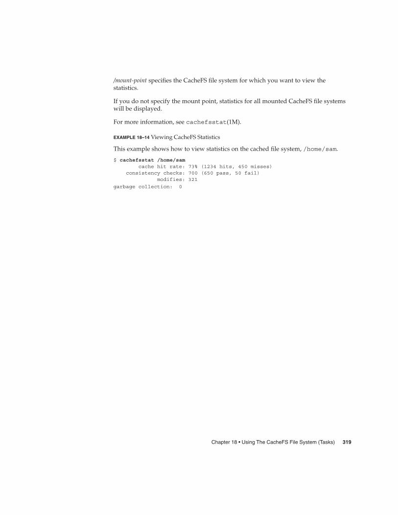
/mount-point specifies the CacheFS file system for which you want to view thestatistics.
If you do not specify the mount point, statistics for all mounted CacheFS file systemswill be displayed.
For more information, see cachefsstat(1M).
EXAMPLE 18–14 Viewing CacheFS Statistics
This example shows how to view statistics on the cached file system, /home/sam.
$ cachefsstat /home/samcache hit rate: 73% (1234 hits, 450 misses)
consistency checks: 700 (650 pass, 50 fail)modifies: 321
garbage collection: 0
Chapter 18 • Using The CacheFS File System (Tasks) 319

320 System Administration Guide: Devices and File Systems • September 2004

CHAPTER 19
Configuring Additional Swap Space(Tasks)
This chapter provides guidelines and step-by-step instructions for configuringadditional swap space after the Solaris release is installed.
This is a list of step-by-step instructions in this chapter.
� “How to Create a Swap File and Make It Available” on page 328� “How to Remove Unneeded Swap Space” on page 329
This is a list of the overview information in this chapter.
� “About Swap Space” on page 321� “How Do I Know If I Need More Swap Space?” on page 324� “How Swap Space Is Allocated” on page 325� “Planning for Swap Space” on page 325� “Monitoring Swap Resources” on page 326� “Adding More Swap Space” on page 327
About Swap SpaceSystem administrators should understand the features of the SunOS swap mechanismto determine the following:
� Swap space requirements� The relationship between swap space and the TMPFS file system� Recovery from error messages related to swap space
321

Swap Space and Virtual MemoryThe Solaris software uses some disk slices for temporary storage rather than for filesystems. These slices are called swap slices. Swap slices are used as virtual memorystorage areas when the system does not have enough physical memory to handlecurrent processes.
The virtual memory system maps physical copies of files on disk to virtual addressesin memory. Physical memory pages that contain the data for these mappings can bebacked by regular files in the file system, or by swap space. If the memory is backedby swap space it is referred to as anonymous memory because there is no identityassigned to the disk space that is backing the memory.
The Solaris environment uses the concept of virtual swap space, a layer betweenanonymous memory pages and the physical storage (or disk-backed swap space) thatactually back these pages. A system’s virtual swap space is equal to the sum of all itsphysical (disk-backed) swap space plus a portion of the currently available physicalmemory.
Virtual swap space has these advantages:
� The need for large amounts of physical swap space is reduced because virtualswap space does not necessarily correspond to physical (disk) storage.
� A pseudo file system called SWAPFS provides addresses for anonymous memorypages. Because SWAPFS controls the allocation of memory pages, it has greaterflexibility in deciding what happens to a page. For example, SWAPFS mightchange the page’s requirements for disk-backed swap storage.
Swap Space and the TMPFS File SystemThe TMPFS file system is activated automatically in the Solaris environment by anentry in the /etc/vfstab file. The TMPFS file system stores files and their associatedinformation in memory (in the /tmp directory) rather than on disk, which speedsaccess to those files. This feature results in a major performance enhancement forapplications such as compilers and DBMS products that use /tmp heavily.
The TMPFS file system allocates space in the /tmp directory from the system’s swapresources. This feature means that as you use up space in the /tmp directory, you arealso using up swap space. So if your applications use the /tmp directory heavily andyou do not monitor swap space usage, your system could run out of swap space.
Use the following if you want to use TMPFS but your swap resources are limited:
� Mount the TMPFS file system with the size option (-o size) to control how muchswap resources TMPFS can use.
� Use your compiler’s TMPDIR environment variable to point to another largerdirectory.
322 System Administration Guide: Devices and File Systems • September 2004

Using your compiler’s TMPDIR variable only controls whether the compiler isusing the /tmp directory. This variable has no effect on other programs’ use of the/tmp directory.
Swap Space as a Dump DeviceA dump device is usually disk space that is reserved to store system crash dumpinformation. By default, a system’s dump device is configured to be an appropriateswap partition. If possible, you should configure a alternate disk partition as adedicated dump device instead to provide increased reliability for crash dumps andfaster reboot time after a system failure. You can configure a dedicated dump deviceby using the dumpadm command. For more information, see Chapter 28, “ManagingSystem Crash Information (Tasks),” in System Administration Guide: AdvancedAdministration.
If you are using a volume manager to manage your disks, such as Solaris VolumeManager, do not configure your dedicated dump device to be under the control ofSolaris Volume Manager. You can keep your swap areas under Solaris VolumeManager’s control, which is a recommended practice. However, for accessibility andperformance reasons, configure another disk as a dedicated dump device outside ofSolaris Volume Manager’s control.
Swap Space and Dynamic ReconfigurationA good practice is to allocate enough swap space to support a failing CPU or systemboard during dynamic reconfiguration. Otherwise, a CPU or system board failuremight result in your host or domain rebooting with less memory.
Without having this additional swap space available, one or more of your applicationsmight fail to start due to insufficient memory, which would require manualintervention to either add additional swap space or to reconfigure the memory usageof these applications.
If you have allocated additional swap to handle a potential loss of memory on reboot,all of your intensive applications might start as usual. This means the system will beavailable to the users, even if possibly slower due to some additional swapping.
For more information, see your specific hardware dynamic reconfiguration guide.
Chapter 19 • Configuring Additional Swap Space (Tasks) 323
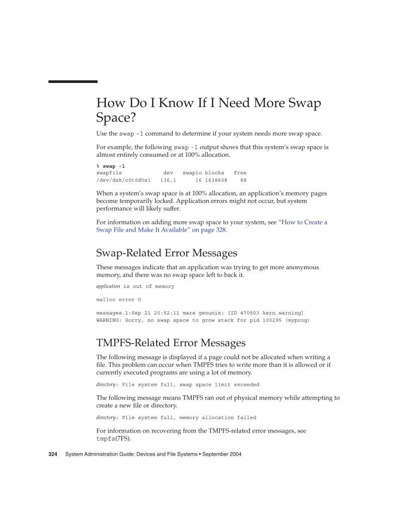
How Do I Know If I Need More SwapSpace?Use the swap -l command to determine if your system needs more swap space.
For example, the following swap -l output shows that this system’s swap space isalmost entirely consumed or at 100% allocation.
% swap -lswapfile dev swaplo blocks free
/dev/dsk/c0t0d0s1 136,1 16 1638608 88
When a system’s swap space is at 100% allocation, an application’s memory pagesbecome temporarily locked. Application errors might not occur, but systemperformance will likely suffer.
For information on adding more swap space to your system, see “How to Create aSwap File and Make It Available” on page 328.
Swap-Related Error MessagesThese messages indicate that an application was trying to get more anonymousmemory, and there was no swap space left to back it.
application is out of memory
malloc error O
messages.1:Sep 21 20:52:11 mars genunix: [ID 470503 kern.warning]
WARNING: Sorry, no swap space to grow stack for pid 100295 (myprog)
TMPFS-Related Error MessagesThe following message is displayed if a page could not be allocated when writing afile. This problem can occur when TMPFS tries to write more than it is allowed or ifcurrently executed programs are using a lot of memory.
directory: File system full, swap space limit exceeded
The following message means TMPFS ran out of physical memory while attempting tocreate a new file or directory.
directory: File system full, memory allocation failed
For information on recovering from the TMPFS-related error messages, seetmpfs(7FS).
324 System Administration Guide: Devices and File Systems • September 2004

How Swap Space Is AllocatedInitially, swap space is allocated as part of the Solaris installation process. If you usethe installation program’s automatic layout of disk slices and do not manually changethe size of the swap slice, the Solaris installation program allocates a default swap areaof 512 Mbytes.
Starting in the Solaris 9 release, the installation program allocates swap space startingat the first available disk cylinder (typically cylinder 0). This placement providesmaximum space for the root (/) file system during the default disk layout and enablesthe growth of the root (/) file system during an upgrade.
For general guidelines on allocating swap space, see “Planning for Swap Space”on page 325.
You can allocate additional swap space to the system by creating a swap file. Forinformation about creating a swap file, see “Adding More Swap Space” on page 327.
The /etc/vfstab FileAfter the system is installed, swap slices and swap files are listed in the /etc/vfstabfile. They are activated by the /sbin/swapadd script when the system is booted.
An entry for a swap device in the /etc/vfstab file contains the following:
� The full path name of the swap slice or swap file� File system type of swap
The file system that contains a swap file must be mounted before the swap file isactivated. So, in the /etc/vfstab file, make sure that the entry that mounts the filesystem comes before the entry that activates the swap file.
Planning for Swap SpaceThe most important factors in determining swap space size are the requirements of thesystem’s software applications. For example, large applications such ascomputer-aided-design simulators, database-management products, transactionmonitors, and geologic analysis systems can consume as much as 200-1000 Mbytes ofswap space.
Consult your application vendor for swap space requirements for their applications.
Chapter 19 • Configuring Additional Swap Space (Tasks) 325
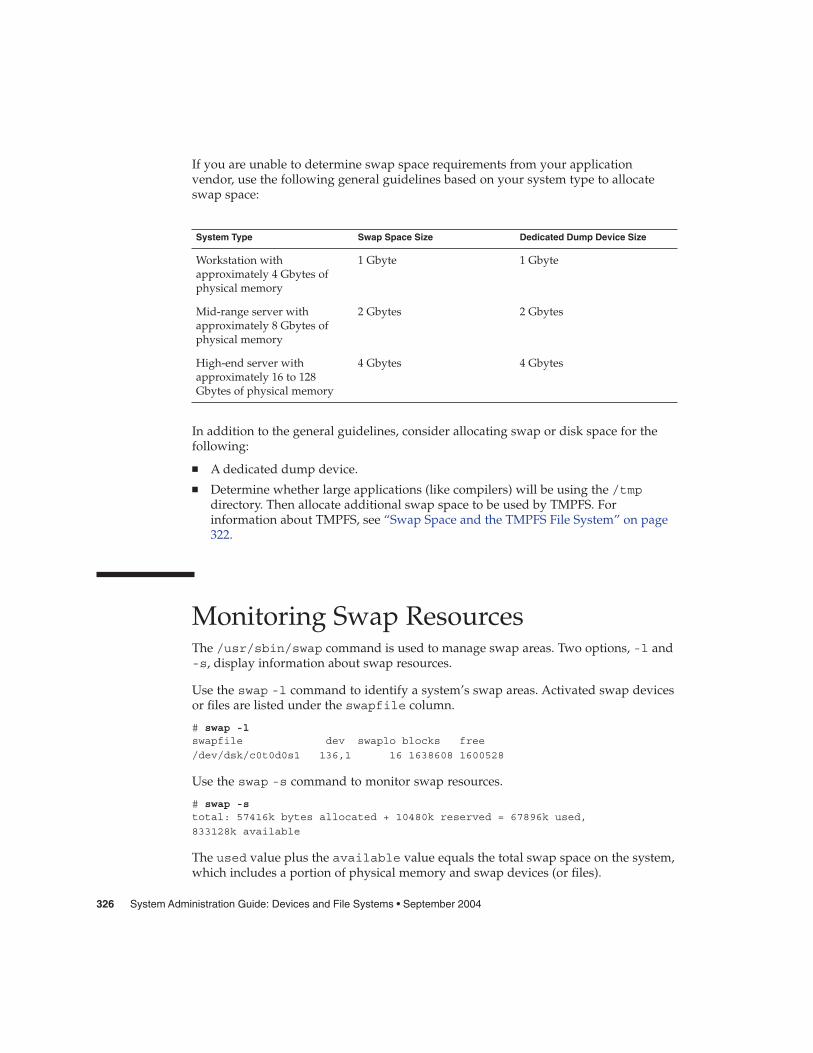
If you are unable to determine swap space requirements from your applicationvendor, use the following general guidelines based on your system type to allocateswap space:
System Type Swap Space Size Dedicated Dump Device Size
Workstation withapproximately 4 Gbytes ofphysical memory
1 Gbyte 1 Gbyte
Mid-range server withapproximately 8 Gbytes ofphysical memory
2 Gbytes 2 Gbytes
High-end server withapproximately 16 to 128Gbytes of physical memory
4 Gbytes 4 Gbytes
In addition to the general guidelines, consider allocating swap or disk space for thefollowing:
� A dedicated dump device.� Determine whether large applications (like compilers) will be using the /tmp
directory. Then allocate additional swap space to be used by TMPFS. Forinformation about TMPFS, see “Swap Space and the TMPFS File System” on page322.
Monitoring Swap ResourcesThe /usr/sbin/swap command is used to manage swap areas. Two options, -l and-s, display information about swap resources.
Use the swap -l command to identify a system’s swap areas. Activated swap devicesor files are listed under the swapfile column.
# swap -lswapfile dev swaplo blocks free
/dev/dsk/c0t0d0s1 136,1 16 1638608 1600528
Use the swap -s command to monitor swap resources.
# swap -stotal: 57416k bytes allocated + 10480k reserved = 67896k used,
833128k available
The used value plus the available value equals the total swap space on the system,which includes a portion of physical memory and swap devices (or files).
326 System Administration Guide: Devices and File Systems • September 2004
You can use the amount of available and used swap space (in the swap -s output) asa way to monitor swap space usage over time. If a system’s performance is good, useswap -s to see how much swap space is available. When the performance of a systemslows down, check the amount of available swap space to see if it has decreased. Thenyou can identify what changes to the system might have caused swap space usage toincrease.
When using this command, keep in mind that the amount of physical memoryavailable for swap usage changes dynamically as the kernel and user processes lockdown and release physical memory.
Note – The swap -l command displays swap space in 512-byte blocks and the swap-s command displays swap space in 1024-byte blocks. If you add up the blocks fromswap -l and convert them to Kbytes, the result will be less than used + available(in the swap -s output) because swap -l does not include physical memory in itscalculation of swap space.
The output from the swap -s command is summarized in the following table.
TABLE 19–1 Output of the swap -s Command
Keyword Description
bytes allocated The total amount of swap space in 1024-byte blocks that iscurrently allocated as backing store (disk-backed swap space).
reserved The total amount of swap space in 1024-byte blocks that is notcurrently allocated, but claimed by memory for possible futureuse.
used The total amount of swap space in 1024-byte blocks that is eitherallocated or reserved.
available The total amount of swap space in 1024-byte blocks that iscurrently available for future reservation and allocation.
Adding More Swap SpaceAs system configurations change and new software packages are installed, you mightneed to add more swap space. The easiest way to add more swap space is to use themkfile and swap commands to designate a part of an existing UFS or NFS filesystem as a supplementary swap area. These commands, described in the followingsections, enable you to add more swap space without repartitioning a disk.
Alternative ways to add more swap space are to repartition an existing disk or addanother disk. For information on how to repartition a disk, see Chapter 10.
Chapter 19 • Configuring Additional Swap Space (Tasks) 327

Creating a Swap FileThe following general steps are involved in creating a swap file:
� Creating a swap file with the mkfile command
� Activating the swap file with the swap command
� Adding an entry for the swap file in the /etc/vfstab file so that the swap file isactivated automatically when the system is booted.
The mkfile CommandThe mkfile command creates a file that is suitable for use as either an NFS-mountedor a local swap area. The sticky bit is set, and the file is filled with zeros. You canspecify the size of the swap file in bytes (the default) or in Kbytes, blocks, or Mbytesby using the k, b, or m suffixes, respectively.
The following table shows the mkfile command options.
TABLE 19–2 Options to the mkfile Command
Option Description
-n Creates an empty file. The size is noted, but the disk blocks are notallocated until data is written to them.
-v Reports the names and sizes of created files.
Caution – Use the -n option only when you create an NFS swap file.
� How to Create a Swap File and Make It Available
1. Become superuser.
You can create a swap file without root permissions. However, to avoid accidentaloverwriting, root should be the owner of the swap file.
2. Create a directory for the swap file, if needed.
3. Create the swap file.
# mkfile nnn[k|b|m] filename
The swap file of the size nnn (in Kbytes, bytes, or Mbytes) and filename you specifyis created.
Steps
328 System Administration Guide: Devices and File Systems • September 2004

4. Activate the swap file.
# /usr/sbin/swap -a /path/filename
You must use the absolute path name to specify the swap file. The swap file isadded and available until the file system is unmounted, the system is rebooted, orthe swap file is removed. Keep in mind that you can’t unmount a file system whilesome process or program is swapping to the swap file.
5. Add an entry for the swap file to the /etc/vfstab file that specifies the fullpath name of the file, and designates swap as the file system type, as follows:
/path/filename - - swap - no -
6. Verify that the swap file is added.
$ /usr/sbin/swap -l
Creating a Swap File and Making It Available
The following examples shows how to create a 100–Mbyte swap file called/files/swapfile.
# mkdir /files# mkfile 100m /files/swapfile# swap -a /files/swapfile# vi /etc/vfstab(An entry is added for the swap file):/files/swapfile - - swap - no -# swap -lswapfile dev swaplo blocks free/dev/dsk/c0t0d0s1 136,1 16 1638608 1600528
/files/swapfile - 16 204784 204784
Removing a Swap File From UseIf you have unneeded swap space, you can remove it.
� How to Remove Unneeded Swap Space
1. Become superuser.
2. Remove the swap space.
# /usr/sbin/swap -d /path/filename
Example 19–1
Steps
Chapter 19 • Configuring Additional Swap Space (Tasks) 329

The swap file name is removed so that it is no longer available for swapping. Thefile itself is not deleted.
3. Edit the /etc/vfstab file and delete the entry for the swap file.
4. Recover the disk space so that you can use it for something else.
# rm /path/filename
If the swap space is a file, remove it. Or, if the swap space is on a separate slice andyou are sure you will not need it again, make a new file system and mount the filesystem.
For information on mounting a file system, see Chapter 17.
5. Verify that the swap file is no longer available.
# swap -l
Removing Unneeded Swap Space
The following examples shows how to delete the /files/swapfile swap file.
# swap -d /files/swapfile# (Remove the swap entry from the /etc/vfstab file)# rm /files/swapfile# swap -lswapfile dev swaplo blocks free
/dev/dsk/c0t0d0s1 136,1 16 1638608 1600528
Example 19–2
330 System Administration Guide: Devices and File Systems • September 2004

CHAPTER 20
Checking UFS File System Consistency(Tasks)
This chapter provides overview information and step-by-step instructions aboutchecking UFS file system consistency.
This is a list of step-by-step instructions in this chapter.
� “How to Check the root (/) or /usr File Systems From an Alternate Boot Device”on page 341
� “How to Check Non-root (/) or Non-/usr File Systems” on page 343� “How to Preen a UFS File System” on page 345� “How to Restore a Bad Superblock” on page 346
This is a list of the overview information in this chapter.
� “File System Consistency” on page 332� “How the File System State Is Recorded” on page 332� “What the fsck Command Checks and Tries to Repair” on page 333� “Interactively Checking and Repairing a UFS File System” on page 340� “Restoring a Bad Superblock” on page 346� “Syntax and Options for the fsck Command” on page 348
For information about fsck error messages, see Chapter 32, “Resolving UFS FileSystem Inconsistencies (Tasks),” in System Administration Guide: AdvancedAdministration.
For background information on the UFS file system structures referred to in thischapter, see Chapter 21.
331

File System ConsistencyThe UFS file system relies on an internal set of tables to keep track of inodes used andavailable blocks. When these internal tables are not properly synchronized with dataon a disk, inconsistencies result and file systems need to be repaired.
File systems can be inconsistent because of abrupt termination of the operating systemin these ways:
� Power failure� Accidental unplugging of the system� Turning off the system without proper shutdown procedure� A software error in the kernel
File system inconsistencies, while serious, are not common. When a system is booted,a check for file system consistency is automatically performed (with the fsckcommand). Most of the time, this file system check repairs problems it encounters.
The fsck command places files and directories that are allocated but unreferenced inthe lost+found directory. A inode number is assigned as the name of unreferencedfile and directory. If the lost+found directory does not exist, the fsck commandcreates it. If there is not enough space in the lost+found directory, the fsckcommand increases its size.
For a description of inodes, see “Inodes” on page 358.
How the File System State Is RecordedThe fsck command uses a state flag, which is stored in the superblock, to record thecondition of the file system. This flag is used by the fsck command to determinewhether a file system needs to be checked for consistency. The flag is used by the/sbin/rcS script during booting and by the fsck -m command. If you ignore theresult from the fsck -m command, all file systems can be checked regardless of thesetting of the state flag.
For a description of the superblock, see “The Superblock” on page 358.
The possible state flag values are described in the following table.
332 System Administration Guide: Devices and File Systems • September 2004

TABLE 20–1 Values of File System State Flags
State Flag Values Description
FSACTIVE Indicates a mounted file system that has modified data in memory. Amounted file system with this state flag indicates that user data ormetadata would be lost if power to the system is interrupted.
FSBAD Indicates that this file system contains inconsistent file system data.
FSCLEAN Indicates an undamaged, cleanly unmounted file system.
FSLOG Indicates that the file system has logging enabled. A file system with thisflag set is either mounted or unmounted. If a file system has loggingenabled, the only flags that it can have are FSLOG or FSBAD. A non-loggingfile system can have FSACTIVE, FSSTABLE, or FSCLEAN.
FSSTABLE Indicates an idle mounted file system. A mounted file system with this stateflag indicates that neither user data nor metadata would be lost if power tothe system is interrupted.
The following table shows how the state flag is modified by the fsck command,based on its initial state.
TABLE 20–2 How the State Flag is Modified by fsck
Initial State: Before fsck State After fsck
No Errors All Errors Corrected Uncorrected Errors
unknown FSSTABLE FSSTABLE unknown
FSACTIVE FSSTABLE FSSTABLE FSACTIVE
FSSTABLE FSSTABLE FSSTABLE FSACTIVE
FSCLEAN FSCLEAN FSSTABLE FSACTIVE
FSBAD FSSTABLE FSSTABLE FSBAD
FSLOG FSLOG FSLOG FSLOG
What the fsck Command Checks andTries to RepairThis section describes what happens in the normal operation of a file system, what cango wrong, what problems the fsck command (the checking and repair utility) looksfor, and how this command corrects the inconsistencies it finds.
Chapter 20 • Checking UFS File System Consistency (Tasks) 333

Why Inconsistencies Might OccurEvery working day hundreds of files might be created, modified, and removed. Eachtime a file is modified, the operating system performs a series of file system updates.These updates, when written to the disk reliably, yield a consistent file system.
When a user program does an operation to change the file system, such as a write, thedata to be written is first copied into an in-core buffer in the kernel. Normally, the diskupdate is handled asynchronously. The user process is allowed to proceed eventhough the data write might not happen until long after the write system call hasreturned. Thus, at any given time, the file system, as it resides on the disk, lags behindthe state of the file system that is represented by the in-core information.
The disk information is updated to reflect the in-core information when the buffer isrequired for another use or when the kernel automatically runs the fsflush daemon(at 30-second intervals). If the system is halted without writing out the in-coreinformation, the file system on the disk might be in an inconsistent state.
A file system can develop inconsistencies in several ways. The most common causesare operator error and hardware failures.
Problems might result from an unclean shutdown, if a system is shut down improperly,or when a mounted file system is taken offline improperly. To prevent uncleanshutdowns, the current state of the file systems must be written to disk (that is,“synchronized”) before you shut down the system, physically take a disk pack out of adrive, or take a disk offline.
Inconsistencies can also result from defective hardware or problems with the disk orcontroller firmware. Blocks can become damaged on a disk drive at any time, or a diskcontroller can stop functioning correctly.
The UFS Components That Are Checked forConsistencyThis section describes the kinds of consistency checks that the fsck command appliesto these UFS file system components: superblock, cylinder group blocks, inodes,indirect blocks, and data blocks.
For information about UFS file system structures, see “The Structure of CylinderGroups for UFS File Systems” on page 357.
Superblock ChecksThe superblock stores summary information, which is the most commonly corruptedcomponent in a UFS file system. Each change to the file system inodes or data blocksalso modifies the superblock. If the CPU is halted and the last command is not a synccommand, the superblock almost certainly becomes corrupted.
334 System Administration Guide: Devices and File Systems • September 2004

The superblock is checked for inconsistencies in the following:
� File system size� Number of inodes� Free block count� Free inode count
File System Size and Inode List Size Checks
The file system size must be larger than the number of blocks used by the superblockand the list of inodes. The number of inodes must be less than the maximum numberallowed for the file system. An inode represents all the information about a file. Thefile system size and layout information are the most critical pieces of information forthe fsck command. Although there is no way to actually check these sizes becausethey are statically determined when the file system is created. However, the fsckcommand can check that the sizes are within reasonable bounds. All other file systemchecks require that these sizes be correct. If the fsck command detects corruption inthe static parameters of the primary superblock, it requests the operator to specify thelocation of an alternate superblock.
For more information about the structure of the UFS file system, see “The Structure ofCylinder Groups for UFS File Systems” on page 357.
Free Block Checks
Free blocks are stored in the cylinder group block maps. The fsck command checksthat all the blocks marked as free are not claimed by any files. When all the blockshave been accounted for, the fsck command checks to see if the number of free blocksplus the number of blocks that are claimed by the inodes equal the total number ofblocks in the file system. If anything is wrong with the block maps, the fsckcommand rebuilds them, leaving out blocks already allocated.
The summary information in the superblock includes a count of the total number offree blocks within the file system. The fsck command compares this count to thenumber of free blocks it finds within the file system. If the counts do not agree, thefsck command replaces the count in the superblock with the actual free-block count.
Free Inode Checks
The summary information in the superblock contains a count of the free inodes withinthe file system. The fsck command compares this count to the number of free inodesit finds within the file system. If the counts do not agree, fsck replaces the count inthe superblock with the actual free inode count.
InodesThe list of inodes is checked sequentially starting with inode 2 (inode 0 and inode 1are reserved). Each inode is checked for inconsistencies in the following:
Chapter 20 • Checking UFS File System Consistency (Tasks) 335
� Format and type� Link count� Duplicate block� Bad block numbers� Inode size
Format and Type of Inodes
Each inode contains a mode word, which describes the type and state of the inode.Inodes might be one of nine types:
� Regular� Directory� Block special� Character special� FIFO (named-pipe)� Symbolic link� Shadow (used for ACLs)� Attribute directory� Socket
Inodes might be in one of three states:
� Allocated� Unallocated� Partially allocated
When the file system is created, a fixed number of inodes are set aside, but they arenot allocated until they are needed. An allocated inode is one that points to a file. Anunallocated inode does not point to a file and, therefore, should be empty. Thepartially allocated state means that the inode is incorrectly formatted. An inode canget into this state if, for example, bad data is written into the inode list because of ahardware failure. The only corrective action the fsck command can take is to clear theinode.
Link Count Checks
Each inode contains a count of the number of directory entries linked to it. The fsckcommand verifies the link count of each inode by examining the entire directorystructure, starting from the root directory, and calculating an actual link count for eachinode.
Discrepancies between the link count stored in the inode and the actual link count asdetermined by the fsck command might be of three types:
� The stored count is not 0 and the actual count is 0.
This condition can occur if no directory entry exists for the inode. In this case, thefsck command puts the disconnected file in the lost+found directory.
336 System Administration Guide: Devices and File Systems • September 2004

� The stored count is not 0 and the actual count is not 0, but the counts are unequal.
This condition can occur if a directory entry has been added or removed, but theinode has not been updated. In this case, the fsck command replaces the storedlink count with the actual link count.
� The stored count is 0 and the actual count is not 0.
In this case, the fsck command changes the link count of the inode to the actualcount.
Duplicate Block Checks
Each inode contains a list, or pointers to lists (indirect blocks), of all the blocks claimedby the inode. Because indirect blocks are owned by an inode, inconsistencies inindirect blocks directly affect the inode that owns the indirect block.
The fsck command compares each block number claimed by an inode to a list ofallocated blocks. If another inode already claims a block number, the block number isput on a list of duplicate blocks. Otherwise, the list of allocated blocks is updated toinclude the block number.
If there are any duplicate blocks, the fsck command makes a second pass of the inodelist to find the other inode that claims each duplicate block. (A large number ofduplicate blocks in an inode might be caused by an indirect block not being written tothe file system.) It is not possible to determine with certainty which inode is in error.The fsck command prompts you to choose which inode should be kept and whichshould be cleared.
Bad Block Number Checks
The fsck command checks each block number claimed by an inode to see that itsvalue is higher than that of the first data block and lower than that of the last datablock in the file system. If the block number is outside this range, it is considered abad block number.
Bad block numbers in an inode might be caused by an indirect block not being writtento the file system. The fsck command prompts you to clear the inode.
Inode Size Checks
Each inode contains a count of the number of data blocks that it references. Thenumber of actual data blocks is the sum of the allocated data blocks and the indirectblocks. The fsck command computes the number of data blocks and compares thatblock count against the number of blocks that the inode claims. If an inode contains anincorrect count, the fsck command prompts you to fix it.
Chapter 20 • Checking UFS File System Consistency (Tasks) 337

Each inode contains a 64-bit size field. This field shows the number of characters (databytes) in the file associated with the inode. A rough check of the consistency of the sizefield of an inode is done by using the number of characters shown in the size field tocalculate how many blocks should be associated with the inode, and then comparingthat to the actual number of blocks claimed by the inode.
Indirect BlocksIndirect blocks are owned by an inode. Therefore, inconsistencies in an indirect blockaffect the inode that owns it. Inconsistencies that can be checked are the following:
� Blocks already claimed by another inode� Block numbers outside the range of the file system
These consistency checks listed are also performed for indirect blocks.
Data BlocksAn inode can directly or indirectly reference three kinds of data blocks. All referencedblocks must be of the same kind. The three types of data blocks are the following:
� Plain data blocks� Symbolic-link data blocks� Directory data blocks
Plain data blocks contain the information stored in a file. Symbolic-link data blockscontain the path name stored in a symbolic link. Directory data blocks containdirectory entries. The fsck command can check only the validity of directory datablocks.
Directories are distinguished from regular files by an entry in the mode field of theinode. Data blocks associated with a directory contain the directory entries. Directorydata blocks are checked for inconsistencies involving the following:
� Directory inode numbers that point to unallocated inodes
� Directory inode numbers that are greater than the number of inodes in the filesystem
� Incorrect directory inode numbers for “.” and “..” directories
� Directories that are disconnected from the file system
Directory Unallocated Checks
If the inode number in a directory data block points to an unallocated inode, the fsckcommand removes the directory entry. This condition can occur if the data blocks thatcontain a new directory entry are modified and written out, but the inode does not getwritten out. This condition can occur if the CPU is shutdown abruptly.
338 System Administration Guide: Devices and File Systems • September 2004

Bad Inode Number Checks
If a directory entry inode number points beyond the end of the inode list, the fsckcommand removes the directory entry. This condition can occur when bad data iswritten into a directory data block.
Incorrect “.” and “..” Entry Checks
The directory inode number entry for “.” must be the first entry in the directory datablock. The directory inode number must reference itself; that is, its value must beequal to the inode number for the directory data block.
The directory inode number entry for “..” must be the second entry in the directorydata block. The directory inode number value must be equal to the inode number ofthe parent directory (or the inode number of itself if the directory is the root directory).
If the directory inode numbers for “.” and “..” are incorrect, the fsck commandreplaces them with the correct values. If there are multiple hard links to a directory,the first hard link found is considered the real parent to which “..” should point. Inthis case, the fsck command recommends that you have it delete the other names.
Disconnected Directories
The fsck command checks the general connectivity of the file system. If a directory isfound that is not linked to the file system, the fsck command links the directory tothe lost+found directory of the file system. This condition can occur when inodesare written to the file system, but the corresponding directory data blocks are not.
Regular Data BlocksData blocks associated with a regular file hold the contents of the file. The fsckcommand does not attempt to check the validity of the contents of a regular file’s datablocks.
The fsck Summary MessageWhen you run the fsck command interactively and it completes successfully, amessage similar to the following is displayed:
# fsck /dev/rdsk/c0t0d0s7** /dev/rdsk/c0t0d0s7** Last Mounted on /export/home** Phase 1 - Check Blocks and Sizes** Phase 2 - Check Pathnames** Phase 3 - Check Connectivity
Chapter 20 • Checking UFS File System Consistency (Tasks) 339

** Phase 4 - Check Reference Counts** Phase 5 - Check Cyl groups2 files, 9 used, 2833540 free (20 frags, 354190 blocks, 0.0% fragmentation)
#
The last line of fsck output describes the following information about the file system:
# files Number of inodes in use
# used Number of fragments in use
# free Number of unused fragments
# frags Number of unused non-block fragments
# blocks Number of unused full blocks
% fragmentation Percentage of fragmentation, where: free fragments x 100 /total fragments in the file system
For information about fragments, see “Fragment Size” on page 362.
Interactively Checking and Repairing aUFS File SystemYou might need to interactively check file systems in the following instances:
� When they cannot be mounted� When they develop inconsistences while in use
When an in-use file system develops inconsistencies, error messages might bedisplayed in the console window, the system messages file, or the system might crash.For example, the system messages file, /var/adm/messages, might includemessages similar to the following:
Sep 5 13:42:40 hostname ufs: [ID 879645 kern.notice] NOTICE: /: unexpected
free inode 630916, run fsck(1M)
hostname is the system reporting the error.
Before using the fsck command, you might want to refer to “Syntax and Options forthe fsck Command” on page 348 and Chapter 32, “Resolving UFS File SystemInconsistencies (Tasks),” in System Administration Guide: Advanced Administration forinformation on resolving fsck error messages.
Keep the following points in mind when running the fsck command to check UFSfile systems:
340 System Administration Guide: Devices and File Systems • September 2004

� A file system should be inactive when using fsck to check that file system. Filesystem changes waiting to be flushed to disk or file system changes that occurduring the fsck checking process can be interpreted as file system corruption andmay not be a reliable indication of a problem.
� A file system must be inactive when using fsck to repair that file system. Filesystem changes waiting to be flushed to disk or file system changes that occurduring the fsck repairing process might cause the file system to become corruptedor might cause the system to crash.
� Unmount a file system before using fsck on that file system, to ensure that it isinactive and that all file system data structures are consistent as possible. The onlyexceptions are for the active root (/) and /usr file systems, because they must bemounted to run fsck.
� If you need to repair the root (/) or /usr file systems, boot the system from analternate device, if possible, so that these file systems are unmounted and inactive.
For step-by-step instructions on running fsck on the root (/) or /usr file system,see “How to Check the root (/) or /usr File Systems From an Alternate BootDevice” on page 341.
� How to Check the root (/) or /usr File SystemsFrom an Alternate Boot DeviceThis procedure assumes that a local CD or network boot server is available so that youcan boot the system from an alternate device.
For information on restoring a bad superblock, see “How to Restore a BadSuperblock” on page 346.
1. Become superuser or assume an equivalent role.
2. For systems with mirrored root (/) file systems only: Detach the root (/) mirrorbefore booting from the alternate device or you risk corrupting the file system.
For information on detaching the root (/) mirror, see “Working With Submirrors”in Solaris Volume Manager Administration Guide.
3. Identify the device, such as /dev/dsk/c0t0d0s0, of the root (/) or /usr filesystem that needs to be checked.
You’ll need to supply this device name when booted from an alternate device. Itwill more difficult to identify this device when you are already booted from thealternate device.
4. Boot the system with the root (/) or /usr file system that needs to be checkedfrom an alternate device, such as a local CD or the network, in single-user modeto ensure that there is no activity on these file systems.
Steps
Chapter 20 • Checking UFS File System Consistency (Tasks) 341
For example:
# init 0ok boot net -s...
#
5. Check the device that contains the root (/) or /usr file system as identified instep #3.
If the hardware for the file system to be checked or repaired has changed, thedevice names might have changed. Be sure to check that the fsck -n messageLast Mounted on ... indicates the expected device for the file system.
For example, the root file system to be checked is /dev/dsk/c0t0d0s0.
# fsck -n /dev/rdsk/c0t0d0s0** /dev/rdsk/c0t0d0s0 (NO WRITE)** Last Mounted on /...fsck /dev/rdsk/c0t0d0s0** /dev/rdsk/c0t0d0s0** Last Mounted on /** Phase 1 - Check Blocks and Sizes** Phase 2 - Check Pathnames..
.
6. Correct any reported fsck errors.
For information about how to respond to the error message prompts whileinteractively checking one or more UFS file systems, see Chapter 32, “ResolvingUFS File System Inconsistencies (Tasks),” in System Administration Guide: AdvancedAdministration.
7. If necessary, run the fsck command again if you see messages similar to thefollowing, FILE SYSTEM STATE NOT SET TO OKAY or FILE SYSTEMMODIFIED.
The fsck command might be unable to fix all errors in one execution.
If fsck cannot repair all of the problems after running it several times, see “Fixinga UFS File System That the fsck Command Cannot Repair” on page 345.
8. Mount the repaired file system to see if there are any files in the lost+founddirectory.
Individual files put in the lost+found directory by the fsck command arerenamed with their inode numbers. If possible, rename the files and move themwhere they belong. You might be able to use the grep command to match phraseswithin individual files and the file command to identify file types.
342 System Administration Guide: Devices and File Systems • September 2004

Eventually, remove unidentifiable files or directories left in the lost+founddirectory so it doesn’t fill it up unnecessarily.
9. Bring the system back to multi-user mode.
# init 6
If you press Control-D when booted in single-user mode from an alternate device,the system will start the Solaris installation process.
10. For systems with mirrored root (/) file systems only: Reattach the root (/) mirror.
� How to Check Non-root (/) or Non-/usr FileSystemsThis procedure assumes that the file system to be checked is unmounted.
For information on restoring a bad superblock, see “How to Restore a BadSuperblock” on page 346.
1. Become superuser or assume an equivalent role.
2. Unmount the local file system first to ensure that there is no activity on the filesystem.
Specify the mount point directory or /dev/dsk/device-name as arguments to thefsck command. Any inconsistency messages are displayed.
For example:
# umount /export/home# fsck /dev/rdsk/c0t0d0s7** /dev/dsk/c0t0d0s7** Last Mounted on /export/home..
.
3. Correct any reported fsck errors.
For information about how to respond to the error message prompts whileinteractively checking one or more UFS file systems, see Chapter 32, “ResolvingUFS File System Inconsistencies (Tasks),” in System Administration Guide: AdvancedAdministration.
4. If necessary, run the fsck command again if you see the following messages,FILE SYSTEM STATE NOT SET TO OKAY or FILE SYSTEM MODIFIED.
The fsck command might be unable to fix all errors in one execution.
Steps
Chapter 20 • Checking UFS File System Consistency (Tasks) 343

If fsck cannot repair all of the problems after running it several times, see “Fixinga UFS File System That the fsck Command Cannot Repair” on page 345.
5. Mount the repaired file system to see if there are any files in the lost+founddirectory.
Individual files put in the lost+found directory by the fsck command arerenamed with their inode numbers. If possible, rename the files and move themwhere they belong. You might be able to use the grep command to match phraseswithin individual files and the file command to identify file types.
Eventually, remove unidentifiable files or directories left in the lost+founddirectory so it doesn’t fill it up unnecessarily.
6. Rename and move any files put in the lost+found directory.
Checking Non-root (/) or Non-/usr File Systems Interactively
The following example shows how to check the /dev/rdsk/c0t0d0s6 file systemand corrects the incorrect block count. This example assumes that the file system isunmounted.
# fsck /dev/rdsk/c0t0d0s6** Phase 1 - Check Block and SizesINCORRECT BLOCK COUNT I=2529 (6 should be 2)CORRECT? y
** Phase 2 - Check Pathnames** Phase 3 - Check Connectivity** Phase 4 - Check Reference Counts** Phase 5 - Cylinder Groups929 files, 8928 used, 2851 free (75 frags, 347 blocks, 0.6%fragmentation)/dev/rdsk/c0t0d0s6 FILE SYSTEM STATE SET TO OKAY
***** FILE SYSTEM WAS MODIFIED *****
Preening UFS File SystemsThe fsck -o p command (p is for preen) checks UFS file systems and automaticallyfixes the problems that normally result from an unexpected system shutdown. Thiscommand exits immediately if it encounters a problem that requires operatorintervention. This command also permits parallel checking of file systems.
You can run the fsck -o p command to preen the file systems after an uncleanshutdown. In this mode, the fsck command does not look at the clean flag and does afull check. These actions are a subset of the actions that the fsck command takeswhen it runs interactively.
Example 20–1
344 System Administration Guide: Devices and File Systems • September 2004

� How to Preen a UFS File SystemThis procedure assumes that the file system is unmounted or inactive.
1. Become superuser or assume an equivalent role.
2. Unmount the UFS file system.
# umount /mount-point
3. Check the UFS file system with the preen option.
# fsck -o p /dev/rdsk/device-name
You can preen individual file systems by using /mount-point or/dev/rdsk/device-name as arguments to the fsck command.
Preening a UFS File System
The following example shows how to preen the /export/home file system.
# fsck -o p /export/home
Fixing a UFS File System That the fsck CommandCannot RepairThe fsck command operates in several passes, and a problem corrected in a later passcan expose other problems that are only detected by earlier passes. Therefore, it issometimes necessary to run fsck repeatedly until it no longer reports any problems,to ensure that all errors have been found and repaired. The fsck command does notkeep running until it comes up clean, so you must rerun it manually.
Pay attention to the information displayed by the fsck command. This informationmight help you fix the problem. For example, the messages might point to a damageddirectory. If you delete the directory, you might find that the fsck command runscleanly.
If the fsck command still cannot repair the file system, you can try to use the ff,clri, and ncheck commands to figure out and fix what is wrong. For informationabout how to use these commands, see fsdb(1M), ff(1M), clri(1M), andncheck(1M). You might, ultimately, need to re-create the file system and restore itscontents from backup media.
For information about restoring complete file systems, see Chapter 25.
If you cannot fully repair a file system but you can mount it read-only, try using thecp, tar, or cpio commands to retrieve all or part of the data from the file system.
Steps
Example 20–2
Chapter 20 • Checking UFS File System Consistency (Tasks) 345

If hardware disk errors are causing the problem, you might need to reformat anddivide the disk into slices again before re-creating and restoring file systems. Checkthat the device cables and connectors are functional before replacing the disk device.Hardware errors usually display the same error again and again across differentcommands. The format command tries to work around bad blocks on the disk. If thedisk is too severely damaged, however, the problems might persist, even afterreformatting. For information about using the format command, see format(1M).For information about installing a new disk, see Chapter 12 or Chapter 13.
Restoring a Bad SuperblockWhen the superblock of a file system becomes damaged, you must restore it. Thefsck command tells you when a superblock is bad. Fortunately, copies of thesuperblock are stored within a file system. You can use the fsck -o b command toreplace the superblock with one of the copies.
For more information about the superblock, see “The Superblock” on page 358.
If the superblock in the root (/) file system becomes damaged and you cannot restoreit, you have two choices:
� Reinstall the system
� Boot from the network or local CD, and attempt the following steps. If these stepsfail, recreate the root (/) file system with the newfs command and restore it from abackup copy.
� How to Restore a Bad Superblock
1. Become superuser or assume an equivalent role.
2. Determine whether the bad superblock is in the root (/) or /usr file system andselect one of the following:
a. Stop the system and boot from the network or a locally-connected CD if thebad superblock is in the root (/) or /usr file system.
From a locally-connected CD, use the following command:
ok boot cdrom -s
From the network where a boot or install server is already setup, use thefollowing command:
Steps
346 System Administration Guide: Devices and File Systems • September 2004

ok boot net -s
If you need help stopping the system, see Chapter 10, “Booting a System(Tasks),” in System Administration Guide: Basic Administration or Chapter 11,“Booting a System (Tasks),” in System Administration Guide: Basic Administration.
b. Change to a directory outside the damaged file system and unmount the filesystem if the bad superblock is not in the root (/) or /usr file system.
# umount /mount-point
Caution – Be sure to use the newfs -N in the next step. If you omit the -Noption, you will destroy all of the data in the file system and replace it with anempty file system.
3. Display the superblock values with the newfs -N command.
# newfs -N /dev/rdsk/device-name
The output of this command displays the block numbers that were used for thesuperblock copies when the newfs command created the file system, unless thefile system was created with special parameters. For information on creating acustomized file system, see “Custom File System Parameters” on page 361.
4. Provide an alternate superblock with the fsck command.
# fsck -F ufs -o b=block-number /dev/rdsk/device-name
The fsck command uses the alternate superblock you specify to restore theprimary superblock. You can always try 32 as an alternate block, or use any of thealternate blocks shown by the newfs -N command.
Restoring a Bad Superblock
The following example shows how to restore the superblock copy 5264.
# newfs -N /dev/rdsk/c0t3d0s7/dev/rdsk/c0t3d0s7: 163944 sectors in 506 cylinders of 9 tracks, 36 sectors83.9MB in 32 cyl groups (16 c/g, 2.65MB/g, 1216 i/g)super-block backups (for fsck -b #) at:32, 5264, 10496, 15728, 20960, 26192, 31424, 36656, 41888,47120, 52352, 57584, 62816, 68048, 73280, 78512, 82976, 88208,93440, 98672, 103904, 109136, 114368, 119600, 124832, 130064, 135296,140528, 145760, 150992, 156224, 161456,# fsck -F ufs -o b=5264 /dev/rdsk/c0t3d0s7Alternate superblock location: 5264.** /dev/rdsk/c0t3d0s7** Last Mounted on** Phase 1 - Check Blocks and Sizes** Phase 2 - Check Pathnames** Phase 3 - Check Connectivity
Example 20–3
Chapter 20 • Checking UFS File System Consistency (Tasks) 347

** Phase 4 - Check Reference Counts** Phase 5 - Check Cyl groups36 files, 867 used, 75712 free (16 frags, 9462 blocks, 0.0% fragmentation)/dev/rdsk/c0t3d0s7 FILE SYSTEM STATE SET TO OKAY
***** FILE SYSTEM WAS MODIFIED *****
#
Syntax and Options for the fsckCommandThe fsck command checks and repairs inconsistencies in file systems. If you run thefsck command without any options, it interactively asks for confirmation beforemaking repairs. This command has four options:
Command and Option Description
fsck -m Checks whether a file system can be mounted
fsck -y Assumes a yes response for all repairs
fsck -n Assumes a no response for all repairs
fsck -o p Noninteractively preens the file system, fixingall expected (innocuous) inconsistencies, butexits when a serious problem is encountered
348 System Administration Guide: Devices and File Systems • September 2004
CHAPTER 21
UFS File System (Reference)
This is a list of the reference information in this chapter.
� “Default Directories for root (/) and /usr File Systems” on page 349� “The Platform-Dependent Directories” on page 357� “The Structure of Cylinder Groups for UFS File Systems” on page 357� “Custom File System Parameters” on page 361� “Commands for Creating a Customized File System” on page 364
Default Directories for root (/) and /usrFile SystemsThe /kernel directory contains only platform-independent objects, including aplatform-independent kernel, genunix. For a description of /platform and/usr/platform, the platform-dependent directories, see Table 21–3.
The following table describes the directories that are contained in the root (/) filesystem.
TABLE 21–1 Default Directories in the root (/) File System
Directory Description
/ Root of the overall file system name space
/dev Primary location for logical device files
/dev/cfg Symbolic links to physical ap_ids
/dev/cua Device files for uucp
349

TABLE 21–1 Default Directories in the root (/) File System (Continued)Directory Description
/dev/dsk Block disk devices
/dev/fbs Frame buffer device files
/dev/fd File descriptors
/dev/md Volume management device names
/dev/printers USB printer device files
/dev/pts pty slave devices
/dev/rdsk Raw disk devices
/dev/rmt Raw tape devices
/dev/sad Entry points for the STREAMS Administrative Driver
/dev/sound Audio device and audio device control files
/dev/swap Default swap device
/dev/term Serial devices
/devices Physical device files
/etc Host-specific system administration configuration files anddatabases
/etc/acct Accounting configuration information
/etc/apache Apache configuration files
/etc/cron.d Configuration information for cron
/etc/default Defaults information for various programs
/etc/dfs Configuration information for shared file systems
/etc/dhcp Dynamic Host Configuration Protocol (DHCP)configuration files
/etc/dmi Solstice Enterprise Agents configuration files
/etc/fn Federated Naming Service and x.500 support files
/etc/fs Binaries organized by file system types
/etc/ftpd ftpd configuration files
/etc/gss Generic Security Service (GSS) Application ProgramInterface configuration files
/etc/gtk GNOME (GNU Network Object Model Environment)configuration files
350 System Administration Guide: Devices and File Systems • September 2004

TABLE 21–1 Default Directories in the root (/) File System (Continued)Directory Description
/etc/inet Configuration files for Internet services
/etc/init.d Scripts for changing run levels
/etc/iplanet iPlanet configuration files
/etc/krb5 Kerberos configuration files
/etc/lib Dynamic linking libraries that are needed when /usr is notavailable
/etc/llc2 Logical link control (llc2) driver configuration files
/etc/lp Configuration information for the printer subsystem
/etc/lu Solaris Live Upgrade configuration files
/etc/lvm Solaris Volume Manager configuration files
/etc/mail Mail subsystem configuration information
/etc/nca Solaris Network Cache and Accelerator (NCA)configuration files
/etc/net Configuration information for TI (transport- independent)network services
/etc/nfs NFS server logging configuration file
/etc/openwin OpenWindows configuration files
/etc/opt Configuration information for optional packages
/etc/ppp Solaris PPP configuration files
/etc/rc0.d Scripts for entering or leaving run level 0
/etc/rc1.d Scripts for entering or leaving run level 1
/etc/rc2.d Scripts for entering or leaving run level 2
/etc/rc3.d Scripts for entering or leaving run level 3
/etc/rcS.d Scripts for bringing the system to single-user mode
/etc/rcm Directory for reconfiguration manager (RCM) custom scripts
/etc/rpcsec Might contain an NIS+ authentication configuration file
/etc/saf Service access facility files (including FIFOs)
/etc/security Basic Security Module (BSM) configuration files
/etc/sfw Samba configuration files
/etc/skel Default profile scripts for new user accounts
Chapter 21 • UFS File System (Reference) 351

TABLE 21–1 Default Directories in the root (/) File System (Continued)Directory Description
/etc/smartcard Solaris SmartCards configuration files
/etc/snmp Solstice Enterprise Agents configuration files
/etc/ssh Secure shell configuration files
/etc/sysevent syseventd configuration files
/etc/tm Trademark files, whose contents are displayed at boot time
/etc/usb USB configuration information
/etc/uucp uucp configuration information
/etc/wrsm WCI Remote Shared Memory (WRSM) configurationinformation
/export Default directory for users’ home directories, client filesystems, or other shared file systems
/home Default directory or mount point for a user’s home directoryon a standalone system. When AutoFS is running, youcannot create any new entries in this directory.
/kernel Directory of platform-independent loadable kernel modulesthat are required as part of the boot process. Includes thegeneric part of the core kernel that is platform-independent,/kernel/genunix. See Table 21–3 for the /platform and/usr/platform directory structure.
/mnt Convenient, temporary mount point for file systems
/opt Default directory or mount point for add-on applicationpackages
/platform Supported platform files. For more information, see Table21–3.
/proc Process information
/sbin Essential executables used in the booting process and inmanual system failure recovery
/tmp Temporary files, whose contents are cleared during bootsequence
/usr Mount point for the /usr file system. For more information,see Table 21–2.
/var Directory for varying files, which usually includestemporary files, logging files, or status files
/var/adm System logging files and accounting files
352 System Administration Guide: Devices and File Systems • September 2004
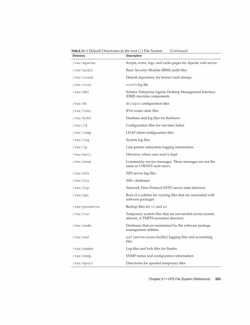
TABLE 21–1 Default Directories in the root (/) File System (Continued)Directory Description
/var/apache Scripts, icons, logs, and cache pages for Apache web server
/var/audit Basic Security Module (BSM) audit files
/var/crash Default depository for kernel crash dumps
/var/cron cron’s log file
/var/dmi Solstice Enterprise Agents Desktop Management Interface(DMI) run-time components
/var/dt dtlogin configuration files
/var/inet IPv6 router state files
/var/krb5 Database and log files for Kerberos
/var/ld Configuration files for run-time linker
/var/ldap LDAP client configuration files
/var/log System log files
/var/lp Line printer subsystem logging information
/var/mail Directory where user mail is kept
/var/news Community service messages. These messages are not thesame as USENET-style news.
/var/nfs NFS server log files
/var/nis NIS+ databases
/var/ntp Network Time Protocol (NTP) server state directory
/var/opt Root of a subtree for varying files that are associated withsoftware packages
/var/preserve Backup files for vi and ex
/var/run Temporary system files that are not needed across systemreboots. A TMPFS-mounted directory.
/var/sadm Databases that are maintained by the software packagemanagement utilities
/var/saf saf (service access facility) logging files and accountingfiles
/var/samba Log files and lock files for Samba
/var/snmp SNMP status and configuration information
/var/spool Directories for spooled temporary files
Chapter 21 • UFS File System (Reference) 353

TABLE 21–1 Default Directories in the root (/) File System (Continued)Directory Description
/var/spool/clientmqueue Sendmail client files
/var/spool/cron cron and at spool files
/var/spool/locks Spooling lock files
/var/spool/lp Line printer spool files
/var/spool/mqueue Mail queued for delivery
/var/spool/pkg Spooled packages
/var/spool/print LP print service client-side request staging area
/var/spool/samba Samba print queue
/var/spool/uucp Queued uucp jobs
/var/spool/uucppublic Files deposited by uucp
/var/statmon Network status monitor files
/var/tmp Directory for temporary files that are not cleared duringboot sequence
/var/uucp uucp log files and status files
/var/yp NIS databases
The following table describes the default directories in the /usr file system.
TABLE 21–2 Default Directories in the /usr File System
Directory Description
4lib SunOS 4.1 binary compatibility package libraries
5bin Symbolic link to the /usr/bin directory
X Symbolic link to the /usr/openwin directory
adm Symbolic link to the /var/adm directory
apache Apache executables, loadable modules, and documentation
aset Directory for Automated Security Enhancement Tools(ASET) programs and files
bin Location for standard system commands
ccs C compilation programs and libraries
demo Demo programs and data
354 System Administration Guide: Devices and File Systems • September 2004

TABLE 21–2 Default Directories in the /usr File System (Continued)Directory Description
dict Symbolic link to the /usr/share/lib/dict directory,which contains the dictionary file used by the UNIX spellprogram
dt Directory or mount point for CDE software
games An empty directory, which is a remnant of the SunOS 4.0-4.1software
include Header files for C programs, and so on.
iplanet Directory server executables, loadable modules, anddocumentation
j2se Java 2 SDK executables, loadable modules, anddocumentation
java* Directories that contain Java programs and libraries
kernel Additional kernel modules
kvm Obsolete
lib Various program libraries, architecture-dependentdatabases, and binaries not invoked directly by the user
local Commands local to a site
mail Symbolic link to the /var/mail directory
man Symbolic link to the /usr/share/man directory
net Directory for network listener services
news Symbolic link to the /var/news directory
oasys Files for the Form and Menu Language Interpreter (FMLI)execution environment
old Programs that are being phased out
openwin Directory or mount point for OpenWindows software
perl5 Perl 5 programs and documentation
platform Supported platform files. For more information, see Table21–3.
preserve Symbolic link to the /var/preserve directory
proc Directory for the proc tools
pub Files for online man page and character processing
Chapter 21 • UFS File System (Reference) 355
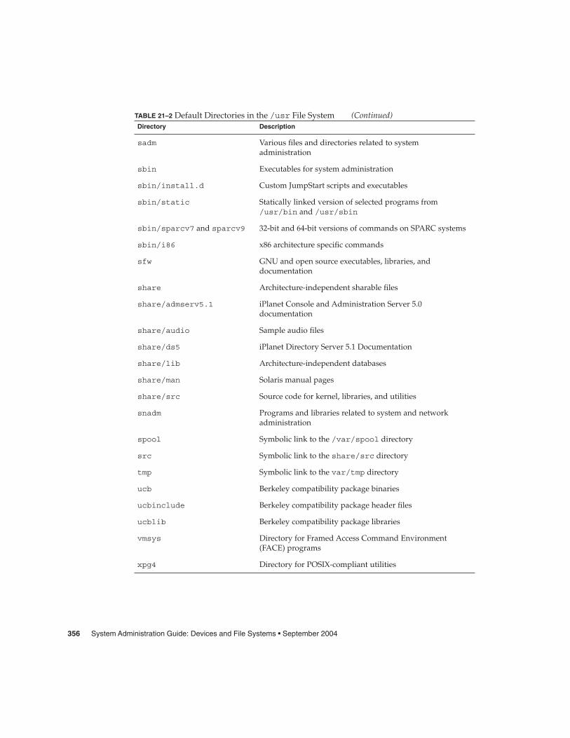
TABLE 21–2 Default Directories in the /usr File System (Continued)Directory Description
sadm Various files and directories related to systemadministration
sbin Executables for system administration
sbin/install.d Custom JumpStart scripts and executables
sbin/static Statically linked version of selected programs from/usr/bin and /usr/sbin
sbin/sparcv7 and sparcv9 32-bit and 64-bit versions of commands on SPARC systems
sbin/i86 x86 architecture specific commands
sfw GNU and open source executables, libraries, anddocumentation
share Architecture-independent sharable files
share/admserv5.1 iPlanet Console and Administration Server 5.0documentation
share/audio Sample audio files
share/ds5 iPlanet Directory Server 5.1 Documentation
share/lib Architecture-independent databases
share/man Solaris manual pages
share/src Source code for kernel, libraries, and utilities
snadm Programs and libraries related to system and networkadministration
spool Symbolic link to the /var/spool directory
src Symbolic link to the share/src directory
tmp Symbolic link to the var/tmp directory
ucb Berkeley compatibility package binaries
ucbinclude Berkeley compatibility package header files
ucblib Berkeley compatibility package libraries
vmsys Directory for Framed Access Command Environment(FACE) programs
xpg4 Directory for POSIX-compliant utilities
356 System Administration Guide: Devices and File Systems • September 2004

The Platform-Dependent DirectoriesThe following table describes the platform-dependent objects in the /platform and/usr/platform directories.
TABLE 21–3 The /platform and /usr/platform Directories
Directory Description
/platform Contains a series of directories, one directory per supportedplatform that needs to reside in the root (/) file system.
/platform/*/kernel Contains platform-dependent kernel components, includingthe file unix, the core kernel that is platform–dependent. Formore information, see kernel(1M).
/usr/platform Contains platform-dependent objects that do not need toreside in the root (/) file system.
/usr/platform/*/lib Contains platform-dependent objects similar to those objectsfound in the /usr/lib directory.
/usr/platform/*/sbin Contains platform-dependent objects similar to those objectsfound in the /usr/sbin directory.
The Structure of Cylinder Groups forUFS File SystemsWhen you create a UFS file system, the disk slice is divided into cylinder groups, whichis made up of one or more consecutive disk cylinders. The cylinder groups are thenfurther divided into addressable blocks to control and organize the structure of thefiles within the cylinder group. Each type of block has a specific function in the filesystem. A UFS file system has these four types of blocks:
Block Type Type of Information Stored
Boot block Information used when booting the system
Superblock Detailed information about the file system
Inode All information about a file
Chapter 21 • UFS File System (Reference) 357
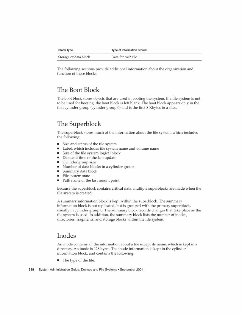
Block Type Type of Information Stored
Storage or data block Data for each file
The following sections provide additional information about the organization andfunction of these blocks.
The Boot BlockThe boot block stores objects that are used in booting the system. If a file system is notto be used for booting, the boot block is left blank. The boot block appears only in thefirst cylinder group (cylinder group 0) and is the first 8 Kbytes in a slice.
The SuperblockThe superblock stores much of the information about the file system, which includesthe following:
� Size and status of the file system� Label, which includes file system name and volume name� Size of the file system logical block� Date and time of the last update� Cylinder group size� Number of data blocks in a cylinder group� Summary data block� File system state� Path name of the last mount point
Because the superblock contains critical data, multiple superblocks are made when thefile system is created.
A summary information block is kept within the superblock. The summaryinformation block is not replicated, but is grouped with the primary superblock,usually in cylinder group 0. The summary block records changes that take place as thefile system is used. In addition, the summary block lists the number of inodes,directories, fragments, and storage blocks within the file system.
InodesAn inode contains all the information about a file except its name, which is kept in adirectory. An inode is 128 bytes. The inode information is kept in the cylinderinformation block, and contains the following:
� The type of the file:
358 System Administration Guide: Devices and File Systems • September 2004

� Regular� Directory� Block special� Character special� FIFO, also known as named pipe� Symbolic link� Socket� Other inodes – attribute directory and shadow (used for ACLs)
� The mode of the file (the set of read-write-execute permissions)
� The number of hard links to the file
� The user ID of the owner of the file
� The group ID to which the file belongs
� The number of bytes in the file
� An array of 15 disk-block addresses
� The date and time the file was last accessed
� The date and time the file was last modified
� The date and time the file was created
The array of 15 disk addresses (0 to 14) points to the data blocks that store the contentsof the file. The first 12 are direct addresses. That is, they point directly to the first 12logical storage blocks of the file contents. If the file is larger than 12 logical blocks, the13th address points to an indirect block, which contains direct block addresses insteadof file contents. The 14th address points to a double indirect block, which containsaddresses of indirect blocks. The 15th address is for triple indirect addresses. Thefollowing figure shows this chaining of address blocks starting from the inode.
Doubleindirectblock
011
Inode
Addressarray
12
13
14
Indirectblock
...
Indirectblock
Indirectblock
Storageblocks
FIGURE 21–1 Address Chain for a UFS File System
Chapter 21 • UFS File System (Reference) 359

Data BlocksData blocks, also called storage blocks, contain the rest of the space that is allocated tothe file system. The size of these data blocks is determined at the time a file system iscreated. Data blocks are allocated, by default, in two sizes: an 8-Kbyte logical blocksize, and a 1-Kbyte fragment size.
For a regular file, the data blocks contain the contents of the file. For a directory, thedata blocks contain entries that give the inode number and the file name of the files inthe directory.
Free BlocksBlocks that are not currently being used as inodes, as indirect address blocks, or asstorage blocks are marked as free in the cylinder group map. This map also keepstrack of fragments to prevent fragmentation from degrading disk performance.
To give you an idea of the appearance of a typical UFS file system, the following figureshows a series of cylinder groups in a generic UFS file system.
Cylinder Group 0
Bootblock (8 Kbytes)
Superblock
Cylinder Group Map
Inodes
Storage Blocks
Cylinder Group 1
Superblock
Cylinder Group Map
Inodes
Storage Blocks
Storage Blocks
Cylinder Group n
Superblock
Cylinder Group Map
Inodes
Storage Blocks
Storage Blocks
FIGURE 21–2 A Typical UFS File System
360 System Administration Guide: Devices and File Systems • September 2004
Custom File System ParametersBefore you choose to alter the default file system parameters that are assigned by thenewfs command, you need to understand them. This section describes each of theseparameters:
� Logical block size� Fragment size� Minimum free space� Rotational delay� Optimization type� Number of files
Logical Block SizeThe logical block size is the size of the blocks that the UNIX kernel uses to read orwrite files. The logical block size is usually different from the physical block size. Thephysical block size is usually 512 bytes, which is the size of the smallest block that thedisk controller can read or write.
Logical block size is set to the page size of the system by default. The default logicalblock size is 8192 bytes (8 Kbytes) for UFS file systems. The UFS file system supportsblock sizes of 4096 or 8192 bytes (4 or 8 Kbytes). The recommended logical block sizeis 8 Kbytes.
SPARC only – You can specify only the 8192-byte block size on the sun4u platform.
To choose the best logical block size for your system, consider both the performancedesired and the available space. For most UFS systems, an 8-Kbyte file systemprovides the best performance, offering a good balance between disk performance andthe use of space in primary memory and on disk.
As a general rule, to increase efficiency, use a larger logical block size for file systemswhere most of the files are very large. Use a smaller logical block size for file systemswhere most of the files are very small. You can use the quot -c file-system commandon a file system to display a complete report on the distribution of files by block size.
However, the page size set when the file system is created is probably best in mostcases.
Chapter 21 • UFS File System (Reference) 361
Fragment SizeAs files are created or expanded, they are allocated disk space in either full logicalblocks or portions of logical blocks called fragments. When disk space is needed for afile, full blocks are allocated first, and then one or more fragments of a block areallocated for the remainder. For small files, allocation begins with fragments.
The ability to allocate fragments of blocks to files, rather than just whole blocks, savesspace by reducing fragmentation of disk space that results from unused holes in blocks.
You define the fragment size when you create a UFS file system. The default fragmentsize is 1 Kbyte. Each block can be divided into 1, 2, 4, or 8 fragments, which results infragment sizes from 8192 bytes to 512 bytes (for 4-Kbyte file systems only). The lowerbound is actually tied to the disk sector size, typically 512 bytes.
For multiterabyte file systems, the fragment size must be equal to the file system blocksize.
Note – The upper bound for the fragment is the logical block size, in which case thefragment is not a fragment at all. This configuration might be optimal for file systemswith very large files when you are more concerned with speed than with space.
When choosing a fragment size, look at the trade-off between time and space: a smallfragment size saves space, but requires more time to allocate. As a general rule, toincrease storage efficiency, use a larger fragment size for file systems where most of thefiles are large. Use a smaller fragment size for file systems where most of the files aresmall.
Minimum Free SpaceThe minimum free space is the percentage of the total disk space that is held in reservewhen you create the file system. The default reserve is ((64 Mbytes/partition size) *100), rounded down to the nearest integer and limited between 1 percent and 10percent, inclusively.
Free space is important because file access becomes less and less efficient as a filesystem gets full. As long as an adequate amount of free space exists, UFS file systemsoperate efficiently. When a file system becomes full, using up the available user space,only root can access the reserved free space.
Commands such as df report the percentage of space that is available to users,excluding the percentage allocated as the minimum free space. When the commandreports that more than 100 percent of the disk space in the file system is in use, someof the reserve has been used by root.
362 System Administration Guide: Devices and File Systems • September 2004
If you impose quotas on users, the amount of space available to the users does notinclude the reserved free space. You can change the value of the minimum free spacefor an existing file system by using the tunefs command.
Rotational DelayThis parameter is obsolete. The value is always set to 0, regardless of the input value.
Optimization TypeThe optimization type parameter is set to either space or time.
� Space – When you select space optimization, disk blocks are allocated to minimizefragmentation and disk use is optimized.
� Time – When you select time optimization, disk blocks are allocated as quickly aspossible, with less emphasis on their placement. When there is enough free space,it is relatively easy to allocate disk blocks effectively, without resulting in too muchfragmentation. The default is time.
You can change the value of the optimization type parameter for an existing filesystem by using the tunefs command.
For more information, see tunefs(1M).
Number of Inodes (Files)The number of bytes per inode specifies the density of inodes in the file system. Thenumber is divided into the total size of the file system to determine the number ofinodes to create. Once the inodes are allocated, you cannot change the numberwithout re-creating the file system.
The default number of bytes per inode is 2048 bytes (2 Kbytes) if the file system is lessthan one Gbyte. If the file system is larger than one Gbyte, the following formula isused:
File System Size Number of Bytes Per Inode
Less than or equal to 1 Gbyte 2048
Less than 2 Gbytes 4096
Less than 3 Gbytes 6144
Chapter 21 • UFS File System (Reference) 363

File System Size Number of Bytes Per Inode
3 Gbytes up to 1 Tbyte 8192
Greater than 1 Tbyte or created with -T option 1048576
If you have a file system with many symbolic links, they can lower the average filesize. If your file system is going to have many small files, you can give this parametera lower value. Note, however, that having too many inodes is much better thanrunning out of inodes. If you have too few inodes, you could reach the maximumnumber of files on a disk slice that is practically empty.
Maximum UFS File and File System SizeThe maximum size of a UFS file system is approximately 16 terabytes of usable space,minus approximately one percent overhead. A sparse file can have a logical size of oneterabyte. However, the actual amount of data that can be stored in a file isapproximately one percent less than one terabyte because of the file system overhead.
Maximum Number of UFS SubdirectoriesThe maximum number of subdirectories per directory in a UFS file system is 32,767.This limit is predefined and cannot be changed.
Commands for Creating a CustomizedFile SystemThis section describes the two commands that you use to create a customized filesystem:
� newfs� mkfs
The newfs Command Syntax, Options, andArgumentsThe newfs command is a friendlier version of the mkfs command that is used tocreate file systems.
The syntax is as follows:
364 System Administration Guide: Devices and File Systems • September 2004

/usr/sbin/newfs [-NTv] [mkfs_options] raw_device
The following table describes the options and arguments for the newfs command.
TABLE 21–4 The newfs Command Options and Arguments
Option Description
-N Displays the file system parameters that would be used increating the file system without actually creating it. This optiondoes not display the parameters that were used to create anexisting file system.
-T Set the parameters of the file system to allow eventual growth toover a terabyte in total file system size. This option sets fragsize tobe the same as bsize, and sets nbpi to 1 Mbyte, unless the -ioption is used to make it even larger. If you use the -f or -ioptions to specify a fragsize or nbpi that is incompatible with thisoption, the user-supplied value of fragsize or nbpi is ignored.
-v Displays the parameters that are passed to the mkfs command.
mkfs-options Use the options in this table, from -a apc to -t track, to set themkfs parameters. Separate the options with spaces.
-a apc The number of alternate sectors per disk cylinder to reserve forbad block placement for SCSI devices only. The default is 0.
This option is not applicable for disks with EFI labels and isignored.
-b bsize The logical block size of the file system, which is either 4096 or8192 bytes. The default is 8192 bytes. The sun4u architecture doesnot support the 4096 block size.
-c cgsize The number of cylinders per cylinder group, which ranges from16 to 256. The default value is calculated by dividing the numberof sectors in the file system by the number of sectors in 1 Gbyte.Then, the result is multiplied by 32. The default value is alwaysbetween 16 to 256.
Use the mkfs command to override the default value.
This option is not applicable for disks with EFI labels and isignored.
Chapter 21 • UFS File System (Reference) 365

TABLE 21–4 The newfs Command Options and Arguments (Continued)Option Description
-C maxcontig The maximum number of logical blocks, belonging to one file,that are allocated contiguously. The default is calculated asfollows:
maxcontig = disk drive maximum transfer size / disk block size
If the disk drive maximum transfer size cannot be determined, thedefault value for maxcontig is calculated as follows:
If maxphys is less than ufs_maxmaxphys, which is typically 1Mbyte, then maxcontig is set to maxphys. Otherwise,maxcontig is set to ufs_maxmaxphys.
You can set maxcontig to any positive integer value.
The actual value will be the lesser of what has been specified andwhat the hardware supports.
You can subsequently change this parameter by using the tunefscommand. For more information, seetunefs(1M).
-d gap Rotational delay. This option is obsolete. The value is always setto 0, regardless of the input value.
-f fragsize The smallest amount of disk space in bytes that can be allocatedto a file. fragsize must be a power of 2 divisor of bsize, where:
bsize / fragsize is 1, 2, 4, or 8.
This means that if the logical block size is 4096, legal values forfragsize are 512, 1024, 2048, and 4096. When the logical block sizeis 8192, legal values are 1024, 2048, 4096, and 8192. The defaultvalue is 1024.
For file systems greater than 1 terabyte or for file systems createdwith the -T option, fragsize is forced to match block size (bsize).
-i nbpi The number of bytes per inode, which specifies the density ofinodes in the file system. The number is divided into the total sizeof the file system to determine the number of inodes to create.
This value should reflect the expected average size of files in thefile system. If fewer inodes are needed, specify a larger number.To create more inodes, specify a smaller number.
For the default values, see “Number of Inodes (Files)” on page363.
366 System Administration Guide: Devices and File Systems • September 2004

TABLE 21–4 The newfs Command Options and Arguments (Continued)Option Description
-m free The minimum percentage of free space to maintain in the filesystem (between 0% and 99%, inclusively). This space is off–limits to regular users. Once the file system is filled to thisthreshold, only the superuser can continue writing to the filesystem.
The default is ((64 Mbytes/partition size) * 100), rounded down tothe nearest integer and limited between 1% and 10%, inclusively.
This parameter can be modified after the file system is created byusing the tunefs command.
-n nrpos The number of different rotation positions in which to divide acylinder group. The default is 8.
This option is not applicable for disks with EFI labels and isignored.
-o opt Optimization type, space or time. The file system can either beinstructed to try to minimize the time spent allocating blocks, or totry to minimize the space fragmentation on the disk. The default istime.
-r rpm The rotational speed of the disk in revolutions per minute. Thissetting is driver- or device-specific.
This parameter is converted to revolutions per second before it ispassed to the mkfs command.
This option is not applicable for disks with EFI labels and isignored.
-s size The size of the file system in sectors. The default is to use theentire partition.
-t ntrack The number of tracks per cylinder on the disk. The default istaken from the disk label.
This option is not applicable for disks with EFI labels and isignored.
raw_device The name of a raw special device residing in the /dev directory(for example, /dev/rdsk/c0t0d0s6) on which to create the filesystem. This argument is required.
EXAMPLE 21–1 newfs Command Options and Arguments
This example shows how to use the -N option to display file system information,including the backup superblocks.
# newfs -N /dev/rdsk/c0t0d0s0/dev/rdsk/c0t0d0s0: 37260 sectors in 115 cylinders of 9 tracks, 36 sectors
19.1MB in 8 cyl groups (16 c/g, 2.65MB/g, 1216 i/g)superblock backups (for fsck -b #) at:
Chapter 21 • UFS File System (Reference) 367

EXAMPLE 21–1 newfs Command Options and Arguments (Continued)
32, 5264, 10496, 15728, 20960, 26192, 31424, 36656,
#
The Generic mkfs CommandThe generic mkfs command calls a file system-specific mkfs command, which thencreates a file system of a specified type on a specified disk slice. Although the mkfscommand can support different types of file systems, in practice you would use it tocreate UFS, UDFS, or PCFS file systems. To make other types of file systems, youwould have to write the software for the file system–specific versions of the mkfscommand to use. Normally, you do not run the mkfs command directly. The mkfscommand is called by the newfs command.
The generic mkfs command is located in the /usr/sbin directory. For a descriptionof the arguments and options, see mkfs(1M).
368 System Administration Guide: Devices and File Systems • September 2004
CHAPTER 22
Backing Up and Restoring FileSystems (Overview)
This chapter provides guidelines and planning information for backing up andrestoring file systems by using the ufsdump and ufsrestore commands.
This is a list of the overview information in this chapter.
� “Where to Find Backup and Restore Tasks” on page 369� “Definition: Backing Up and Restoring File Systems” on page 370� “Why You Should Back Up File Systems” on page 371� “Planning Which File Systems to Back Up” on page 371� “Choosing the Type of Backup” on page 373� “Choosing a Tape Device” on page 374� “High-Level View of Backing Up and Restoring File Systems (Task Map)” on page
374� “Guidelines for Scheduling Backups” on page 375� “Sample Backup Schedules” on page 379
Where to Find Backup and Restore Tasks
Backup or Restore Task For More Information
Back up file systems by using the ufsdumpcommand
Chapter 23
Create UFS snapshots by using the fssnapcommand
Chapter 24
Restore file systems by using the ufsrestorecommand
Chapter 25
369

Backup or Restore Task For More Information
Copy files and directories by using the cpio,dd, pax, and cpio commands
Chapter 27
Definition: Backing Up and RestoringFile SystemsBacking up file systems means copying file systems to removable media, such as tape,to safeguard against loss, damage, or corruption. Restoring file systems means copyingreasonably current backup files from removable media to a working directory.
This chapter describes the ufsdump and ufsrestore commands for backing up andrestoring UFS file systems. Other commands are available for copying files and filesystems for the purpose of sharing or transporting files. The following table providespointers to all commands that copy individual files and file systems to other media.
TABLE 22–1 Commands for Backing Up and Restoring Files and File Systems
Task Command For More Information
Back up one or more file systems toa local tape device or a remote tapedevice
ufsdump Chapter 23 or Chapter 26
Create read-only copies of filesystems
fssnap Chapter 24
Back up all file systems for systemson a network from a backup server
Solstice Backup software Solstice Backup 5.1Administration Guide
Back up and restore an NIS+ masterserver
nisbackup andnisrestore
System AdministrationGuide: Naming and DirectoryServices (FNS and NIS+)
Copy, list, and retrieve files on tapeor diskette
tar, cpio, or pax Chapter 27
Copy master disk to a clone disk dd Chapter 27
Restore complete file systems orindividual files from removablemedia to a working directory
ufsrestore Chapter 25
370 System Administration Guide: Devices and File Systems • September 2004

Why You Should Back Up File SystemsBacking up files is one of the most crucial system administration functions. You shouldperform regularly scheduled backups to prevent loss of data due to the followingtypes of problems:
� System crashes� Accidental deletion of files� Hardware failures� Natural disasters such as fire, hurricanes, or earthquakes� Problems when you reinstall or upgrade a system
Planning Which File Systems to Back UpYou should back up all file systems that are critical to users, including file systems thatchange frequently. The following tables provide general guidelines on the file systemsto back up for standalone systems and servers.
TABLE 22–2 File Systems to Back Up for Standalone Systems
File System to Back Up Description Back Up Interval
root (/) – slice 0 This file system contains thekernel and possibly the/var directory. The /vardirectory might includefrequently modified filessuch as mail andaccounting files.
At regular intervals such as weeklyor daily
/usr – slice 6, /opt The installation of newsoftware and newcommands typically affectsthe /usr and /opt filesystems. The /optdirectory is either part ofroot (/) or is its own filesystem.
Occasionally
/export/home – slice 7 This file system contains thedirectories andsubdirectories of all userson the standalone system.
More often than root (/) or /usr,perhaps as often as once a day,depending on your site’s needs
Chapter 22 • Backing Up and Restoring File Systems (Overview) 371

TABLE 22–2 File Systems to Back Up for Standalone Systems (Continued)File System to Back Up Description Back Up Interval
/export , /var, or otherfile systems
During installation ofSolaris software, you mighthave created these filesystems.
As your site requires
TABLE 22–3 File Systems to Back Up for Servers
File System to Back Up Description Back Up Interval
root (/) – slice 0 This file systemcontains the kernel andexecutables.
Once a day to once a month dependingon your site’s needs.
If you frequently add and remove usersand systems on the network, you have tochange configuration files in this filesystem. In this case, you should do a fullbackup of the root (/) file system atintervals between once a week and once amonth.
If your site keeps user mail in the/var/mail directory on a mail server,which client systems then mount, youmight want to back up root (/) daily. Or,backup the /var directory, if it is aseparate file system.
/export – slice 3 This file system cancontain the kernel andexecutables for disklessclients.
Once a day to once a month, dependingon your site’s needs.
Because the information in this filesystem is similar to the server’s rootdirectory in slice 0, the file system doesnot change frequently. You need to backup this file system only occasionally,unless your site delivers mail to clientsystems. Then, you should back up/export more frequently.
/usr – slice 6, /opt An optional file systemgenerally used to storenon-system software.
Once a day to once a month, dependingon your site’s needs.
These file systems are fairly static andneed to be backed up once a week toonce a month.
372 System Administration Guide: Devices and File Systems • September 2004
TABLE 22–3 File Systems to Back Up for Servers (Continued)File System to Back Up Description Back Up Interval
/export/home – slice 7 This file systemcontains the homedirectories of all theusers on the system.The files in this filesystem are volatile.
Once a day to once a week.
Choosing the Type of BackupYou can perform full or incremental backups by using the ufsdump command. Youcan create a temporary image of a file system by using the fssnap command. Thefollowing table lists the differences between these types of backup procedures.
TABLE 22–4 Differences Between Types of Backups
Backup Type Result Advantages Disadvantages
Full Copies a complete filesystem or directory
All data is in one place Requires large numbersof backup tapes thattake a long time towrite. Takes longer toretrieve individual filesbecause the drive has tomove sequentially to thepoint on the tape wherethe file is located. Youmight have to searchmultiple tapes.
Snapshot Creates a temporaryimage of a file system
System can be inmultiuser mode
System performancemight degrade while thesnapshot is created.
Incremental Copies only those filesin the specified filesystem that havechanged since aprevious backup
Easier to retrieve smallchanges in file systems
Finding whichincremental tapecontains a file can taketime. You might have togo back to the last fullbackup.
Chapter 22 • Backing Up and Restoring File Systems (Overview) 373

Choosing a Tape DeviceThe following table shows typical tape devices that are used for storing file systemsduring the backup process. The storage capacity depends on the type of drive and thedata being written to the tape. For more information on tape devices, see Chapter 28.
TABLE 22–5 Typical Media for Backing Up File Systems
Backup Media Storage Capacity
1/2-inch reel tape 140 Mbytes (6250 bpi)
2.5-Gbyte 1/4–inch cartridge (QIC) tape 2.5 Gbytes
DDS3 4-mm cartridge tape (DAT) 12–24 Gbytes
14-Gbyte 8-mm cartridge tape 14 Gbytes
DLT 7000 1/2-inch cartridge tape 35–70 Gbytes
High-Level View of Backing Up andRestoring File Systems (Task Map)Use this task map to identify all the tasks for backing up and restoring file systems.Each task points to a series of additional tasks, such as determining the type of backupto perform.
Task Description For Instructions
1. Identify the filesystems to back up
Identify which file systems need to bebacked up on a daily, weekly, ormonthly basis.
“Planning Which FileSystems to Back Up”on page 371
2. Determine the type ofbackup
Determine the type of backup youneed for the file systems at your site.
“Choosing the Type ofBackup” on page 373
3. Create the backup Use one of the following methods:
If you want to have full andincremental backups of your filesystems, use the ufsdump command.
Chapter 23
374 System Administration Guide: Devices and File Systems • September 2004

Task Description For Instructions
If you want to create a snapshot of filesystem while it is active and mounted,consider using the fssnap command.
Chapter 24
If you want to create a snapshot of filesystem while it is active and mounted,consider using the fssnap command.
Chapter 27
4. (Optional) Restore afile system
Select the restoration method that isbased on the command used to backup the files or file system:
Restore a file system backup that wascreated with the ufsdump command.
Chapter 25
Restore a file system that was createdwith the tar, cpio, or pax command.
Chapter 27
5. (Optional) Restore theroot (/) or /usr filesystem
Restoring the root (/) or /usr filesystem is more complicated thanrestoring a non critical file system. Youneed to boot from a local CD or fromthe network while these file systemsare being restored.
“How to Restore the root(/) and /usr File Systems”on page 418
Guidelines for Scheduling BackupsA backup schedule is the schedule that you establish to run the ufsdump command.This section discusses guidelines on the factors to weigh when you create a backupschedule. This section also includes sample backup schedules.
The backup schedule that you create depends on the following:
� Your need to minimize the number of tapes that are used for backups
� The time available for doing backups
� The time available for doing a full restore of a damaged file system
� The time available for retrieving individual files that are accidentally deleted
How Often Should You Do Backups?If you do not need to minimize time and the number of media that is used forbackups, you can do full backups every day. However, this backup method is notrealistic for most sites, so incremental backups are used most often. In this case, you
Chapter 22 • Backing Up and Restoring File Systems (Overview) 375

should back up your site enough to so that you can restore files from the last fourweeks. This schedule requires at least four sets of tapes, one set for each week. Youwould then reuse the tapes each month. In addition, you should archive the monthlybackups for at least a year. Then, keep yearly backups for a number of years.
Backup Terms and DefinitionsThe following table describes backup terms and definitions.
Term Definition
Snapshot Creates a temporary image of a file system.
Full backup Copies a complete file system or directory.
Incremental backup Copies only those files in the specified file system that havechanged since a previous backup. Incremental backup typesinclude the following:� Daily, cumulative – Copies a day’s worth of file changes
on Monday. Then, overwrites Monday’s backup with filechanges from Tuesday, Wednesday, and so on.
� Daily, incremental – Copies a day’s worth of file changesso that you have distinct tapes of Monday’s changes,Tuesday’s changes, and so on.
� Weekly cumulative – Copies the files that have changedduring the week and includes the previous week’s filechanges.
� Weekly incremental – Copies the files that have changedduring the week since the previous weekly backup.
Suggestions for Scheduling BackupsThe following table provides other suggestions for scheduling backups.
376 System Administration Guide: Devices and File Systems • September 2004

TABLE 22–6 Suggestions for Backup Schedules
File Restoration Need Backup Interval Comments
To restore different versionsof files (for example, filesystems that are used forword processing)
Do daily incrementalbackups every working day
Do not reuse the same tapefor daily incrementalbackups
This schedule saves all filesmodified that day, as well as thosefiles still on disk that were modifiedsince the last backup of a lowerlevel. However, with this schedule,you should use a different tape eachday because you might otherwisebe unable to restore the neededversion of the file.
For example, a file that changed onTuesday, and again on Thursday,goes onto Friday’s lower-levelbackup appearing as it didThursday night, not Tuesday night.If a user needs the Tuesday version,you cannot restore it unless youhave a Tuesday backup tape (or aWednesday backup tape). Similarly,a file that is present on Tuesday andWednesday, but removed onThursday, does not appear on theFriday lower-level backup.
To quickly restore acomplete file system
Do lower-level backupsmore frequently.
—
To back up a number of filesystems on the same server
Consider staggering theschedule for different filesystems.
This way you’re not doing all level0 backups on the same day.
To minimize tapes Increase the level ofincremental backups thatare done across the week.
Only changes from day to day aresaved on each daily tape.
Increase the level ofbackups that are done atthe end of the week. Puteach day’s and week’sincremental backups ontothe same tape.
Only changes from week to week(rather than the entire month) aresaved on the weekly tapes.
Put each day’s and week’sincremental backups ontothe same tape.
To do so, use the no rewind optionof the ufsdump command, such asspecifying /dev/rmt/0n.
Chapter 22 • Backing Up and Restoring File Systems (Overview) 377

Using Dump Levels to Create Incremental BackupsThe dump level you specify in the ufsdump command (0–9) determines which filesare backed up. Dump level 0 creates a full backup. Levels 1–9 are used to scheduleincremental backups, but have no defined meanings. Levels 1–9 are just a range ofnumbers that are used to schedule cumulative or discrete backups. The only meaninglevels 1–9 have is in relationship to each other, as a higher or lower number. A lowerdump number always restarts a full or a cumulative backup. The following examplesshow the flexibility of the incremental dump procedure using levels 1–9.
Example—Dump Levels for Daily, Cumulative BackupsDoing daily, cumulative incremental backups is the most commonly used backupschedule and is recommended for most situations. The following example shows aschedule that uses a level 9 dump Monday through Thursday, and a level 5 dump onFriday to restart the process.
Monthly
0
Monday
9
Tuesday
9
Wednesday
9
Thursday
9
Friday
5
FIGURE 22–1 Incremental Backup: Daily Cumulative
In the preceding example, you could have used other numbers in the 1–9 range toproduce the same results. The key is using the same number Monday throughThursday, with any lower number on Friday. For example, you could have specifiedlevels 4, 4, 4, 4, 2 or 7, 7, 7, 7, 5.
Example—Dump Levels for Daily, Incremental BackupsThe following example shows a schedule where you capture only a day’s work ondifferent tapes. This type of backup is referred to as a daily, incremental backup. Inthis case, sequential dump level numbers are used during the week (3, 4, 5, 6) with alower number (2) on Friday. The lower number on Friday restarts the processing.
378 System Administration Guide: Devices and File Systems • September 2004

Monthly
0
Monday
3
Tuesday
4
Wednesday
5
Thursday
6
Friday
2
FIGURE 22–2 Incremental Backup: Daily Incremental
In the preceding example, you could have used the sequence 6, 7, 8, 9 followed by 2,or 5, 6, 7, 8 followed by 3. Remember, the numbers themselves have no definedmeaning. You attribute meaning by ordering them in a specified sequence, asdescribed in the examples.
Sample Backup SchedulesThis section provides sample backup schedules. All schedules assume that you beginwith a full backup (dump level 0), and that you use the -u option to record eachbackup in the /etc/dumpdates file.
Example—Daily Cumulative, Weekly CumulativeBackupsTable 22–7 shows the most commonly used incremental backup schedule. Thisschedule is recommended for most situations. With this schedule, the followingoccurs:
� All files that have changed since the lower-level backup at the end of the previousweek are saved each day.
� For each weekday level 9 backup, the previous level 0 or level 5 backup is theclosest backup at a lower level. Therefore, each weekday tape contains all the filesthat changed since the end of the previous week or the initial level 0 backup for thefirst week.
� For each Friday level 5 backup, the closest lower-level backup is the level 0 backupdone at the beginning of the month. Therefore, each Friday’s tape contains all thefiles changed during the month up to that point.
Chapter 22 • Backing Up and Restoring File Systems (Overview) 379

TABLE 22–7 Daily Cumulative or Weekly Cumulative Backup Schedule
Floating Mon Tues Wed Thurs Fri
1st of Month 0
Week 1 9 9 9 9 5
Week 2 9 9 9 9 5
Week 3 9 9 9 9 5
Week 4 9 9 9 9 5
The following table shows how the contents of the tapes can change across two weekswith the daily cumulative, weekly cumulative schedule. Each letter represents adifferent file.
TABLE 22–8 Contents of Tapes for Daily Cumulative/Weekly Cumulative Backup Schedule
Mon Tues Wed Thurs Fri
Week 1 a b a b c a b c d a b c d e a b c d e f
Week 2 g g h g h i g h i j a b c d e f g h i j k
Tape Requirements for the Daily Cumulative, WeeklyCumulative ScheduleWith this schedule, you need six tapes if you want to reuse daily tapes. However, youneed nine tapes if you want to use four different daily tapes:
� One tape for the level 0 backup� Four tapes for Fridays� One or four daily tapes
If you need to restore a complete file system, you need the following tapes:
� The level 0 tape� The most recent Friday tape� The most recent daily tape since the last Friday tape, if any
Example—Daily Cumulative, Weekly IncrementalBackupsThe following table shows a schedule where each weekday tape accumulates all filesthat changed since the beginning of the week, or the initial level 0 backup for the firstweek. In addition, each Friday’s tape contains all the files that changed that week.
380 System Administration Guide: Devices and File Systems • September 2004

TABLE 22–9 Daily Cumulative, Weekly Incremental Backup Schedule
Floating Mon Tues Wed Thurs Fri
1st of Month 0
Week 1 9 9 9 9 3
Week 2 9 9 9 9 4
Week 3 9 9 9 9 5
Week 4 9 9 9 9 6
The following table shows how the contents of the tapes can change across two weekswith the daily cumulative, weekly incremental backup schedule. Each letter representsa different file.
TABLE 22–10 Contents of Tapes for Daily Cumulative, Weekly Incremental Backup Schedule
Mon Tues Wed Thurs Fri
Week 1 a b a b c a b c d a b c d e a b c d e f
Week 2 g g h g h i g h i j g h i j k
Tape Requirements for the Daily Cumulative, WeeklyIncremental Backup ScheduleWith this schedule, you need six tapes if you want to reuse daily tapes. However, youneed nine tapes if you want to use four different daily tapes:
� One tape for the level 0 backup� Four tapes for Fridays� One or four daily tapes
If you need to restore a complete file system, you need the following tapes:
� The level 0 tape� All the Friday tapes� The most recent daily tape since the last Friday tape, if any
Example—Daily Incremental, Weekly CumulativeBackupsThe following table shows a schedule where each weekday tape contains only the filesthat changed since the previous day. In addition, each Friday’s tape contains all fileschanged since the initial level 0 backup at the beginning of the month.
Chapter 22 • Backing Up and Restoring File Systems (Overview) 381

TABLE 22–11 Daily Incremental, Weekly Cumulative Backup Schedule
Floating Mon Tues Wed Thurs Fri
1st of Month 0
Week 1 3 4 5 6 2
Week 2 3 4 5 6 2
Week 3 3 4 5 6 2
Week 4 3 4 5 6 2
The following table shows how the contents of the tapes can change across two weekswith the daily incremental, weekly cumulative schedule. Each letter represents adifferent file.
TABLE 22–12 Contents of Tapes for Daily Incremental, Weekly Cumulative Backup Schedule
Mon Tues Wed Thurs Fri
Week 1 a b c d e f g hi a b c d e f g h i
Week 2 j k l m n o p q a b c d e f g h i j kl m n o p q r s
Tape Requirements for Daily Incremental, WeeklyCumulative ScheduleWith this schedule, you need at least 9 tapes if you want to reuse daily tapes, which isnot recommended. Preferably, you need 21 tapes if you save weekly tapes for a month:one tape for the level 0, four tapes for the Fridays, and four or 16 daily tapes.
� 1 tape for the level 0 backup.� 4 tapes for all the Friday backups.� 4 or 16 daily tapes.
If you need to restore the complete file system, you need the following tapes:
� The level 0 tape.� The most recent Friday tape.� All the daily tapes since the last Friday tape, if any.
Example—Monthly Backup Schedule for a ServerThe following table shows an example backup strategy for a heavily used file serveron a small network where users are doing file-intensive work, such as programdevelopment or document production. This example assumes that the backup periodbegins on a Sunday and consists of four seven-day weeks.
382 System Administration Guide: Devices and File Systems • September 2004

TABLE 22–13 Example of Monthly Backup Schedule for a Server
Directory Date Dump Level Tape Name
root (/) 1st Sunday 0 n tapes
/usr 1st Sunday 0 n tapes
/export 1st Sunday 0 n tapes
/export/home 1st Sunday 0 n tapes
1st Monday 9 A
1st Tuesday 9 B
1st Wednesday 5 C
1st Thursday 9 D
1st Friday 9 E
1st Saturday 5 F
root (/) 2nd Sunday 0 n tapes
/usr 2nd Sunday 0 n tapes
/export 2nd Sunday 0 n tapes
/export/home 2nd Sunday 0 n tapes
2nd Monday 9 G
2nd Tuesday 9 H
2nd Wednesday 5 I
2nd Thursday 9 J
2nd Friday 9 K
2nd Saturday 5 L
root (/) 3rd Sunday 0 n tapes
/usr 3rd Sunday 0 n tapes
/export 3rd Sunday 0 n tapes
/export/home 3rd Sunday 0 n tapes
3rd Monday 9 M
3rd Tuesday 9 N
3rd Wednesday 5 O
3rd Thursday 9 P
Chapter 22 • Backing Up and Restoring File Systems (Overview) 383
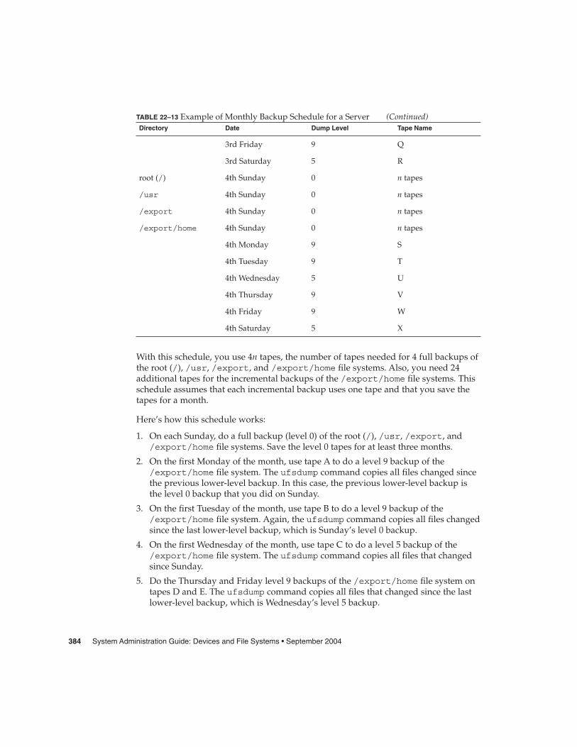
TABLE 22–13 Example of Monthly Backup Schedule for a Server (Continued)Directory Date Dump Level Tape Name
3rd Friday 9 Q
3rd Saturday 5 R
root (/) 4th Sunday 0 n tapes
/usr 4th Sunday 0 n tapes
/export 4th Sunday 0 n tapes
/export/home 4th Sunday 0 n tapes
4th Monday 9 S
4th Tuesday 9 T
4th Wednesday 5 U
4th Thursday 9 V
4th Friday 9 W
4th Saturday 5 X
With this schedule, you use 4n tapes, the number of tapes needed for 4 full backups ofthe root (/), /usr, /export, and /export/home file systems. Also, you need 24additional tapes for the incremental backups of the /export/home file systems. Thisschedule assumes that each incremental backup uses one tape and that you save thetapes for a month.
Here’s how this schedule works:
1. On each Sunday, do a full backup (level 0) of the root (/), /usr, /export, and/export/home file systems. Save the level 0 tapes for at least three months.
2. On the first Monday of the month, use tape A to do a level 9 backup of the/export/home file system. The ufsdump command copies all files changed sincethe previous lower-level backup. In this case, the previous lower-level backup isthe level 0 backup that you did on Sunday.
3. On the first Tuesday of the month, use tape B to do a level 9 backup of the/export/home file system. Again, the ufsdump command copies all files changedsince the last lower-level backup, which is Sunday’s level 0 backup.
4. On the first Wednesday of the month, use tape C to do a level 5 backup of the/export/home file system. The ufsdump command copies all files that changedsince Sunday.
5. Do the Thursday and Friday level 9 backups of the /export/home file system ontapes D and E. The ufsdump command copies all files that changed since the lastlower-level backup, which is Wednesday’s level 5 backup.
384 System Administration Guide: Devices and File Systems • September 2004

6. On the first Saturday of the month, use tape F to do a level 5 backup of/export/home. The ufsdump command copies all files changed since theprevious lower-level backup (in this case, the level 0 backup you did on Sunday).Store tapes A-F until the first Monday of the next four-week period, when you usethem again.
7. Repeat steps 1–6 for the next three weeks, using tapes G–L and 4n tapes for thelevel 0 backup on Sunday, and so on.
8. For each four-week period, repeat steps 1–7, using a new set of tapes for the level 0backups and reusing tapes A–X for the incremental backups. The level 0 tapescould be reused after three months.
This schedule lets you save files in their various states for a month. This planrequires many tapes, but ensures that you have a library of tapes to draw upon. Toreduce the number of tapes, you could reuse Tapes A–F each week.
Chapter 22 • Backing Up and Restoring File Systems (Overview) 385

386 System Administration Guide: Devices and File Systems • September 2004

CHAPTER 23
Backing Up Files and File Systems(Tasks)
This chapter describes the procedures for backing up file systems by using theufsdump command.
For information on these procedures, see “Backing Up Files and File System (TaskMap)” on page 387.
For overview information about performing backups, see Chapter 22.
For detailed information on the ufsdump command syntax, options, and arguments,see Chapter 26.
Backing Up Files and File System (TaskMap)
Task Description For Instructions
1. Prepare for file systembackups
Identify the file systems, the type ofbackup, and the tape device to be usedfor the backups.
“Preparing for File SystemBackups” on page 388
2. Determine the numberof tapes needed to backup a file system
Determine the number of tapes thatare needed for a full backup of a filesystem.
“How to Determine theNumber of Tapes Neededfor a Full Backup” on page389
387

Task Description For Instructions
3. Back up file systems Perform a full backup of file systemsto get baseline copies of all files.
Perform an incremental backup of filesystems based on whether keepingcopies of files that have changed on adaily basis is important at your site.
“How to Backup a FileSystem to Tape” on page390
Preparing for File System BackupsThe preparation for backing up file systems begins with planning, which is describedin Chapter 22 and includes choosing the following:
� The file systems to back up� The type of backup (full or incremental) to perform� A backup schedule� A tape drive
For more information, see Chapter 22.
This section describes two other tasks you might need to perform before you back upfile systems:
� Finding the names of file systems to back up� Determining the number of tapes that are needed for a full backup
� How to Find File System Names
1. Display the contents of the /etc/vfstab file.
$ more /etc/vfstab
2. Look in the mount point column for the name of the file system.
3. Use the directory name listed in the mount point column when you back upthe file system.
Finding File System Names
In this example, the file systems to be backed up are root (/), /usr, /datab, and/export/home.
$ more /etc/vfstab#device device mount FS fsck mount mount
Steps
Example 23–1
388 System Administration Guide: Devices and File Systems • September 2004

#to mount to fsck point type pass at boot options#fd - /dev/fd fd - no -/proc - /proc proc - no -/dev/dsk/c0t0d0s1 - - swap - no -/dev/dsk/c0t0d0s0 /dev/rdsk/c0t0d0s0 / ufs 1 no -/dev/dsk/c0t0d0s6 /dev/rdsk/c0t0d0s6 /usr ufs 1 no -/dev/dsk/c0t0d0s5 /dev/rdsk/c0t0d0s5 /datab ufs 2 yes -/dev/dsk/c0t0d0s7 /dev/rdsk/c0t0d0s7 /export/home ufs 2 yes -
swap - /tmp tmpfs - yes -
� How to Determine the Number of Tapes Neededfor a Full Backup
1. Become superuser or assume an equivalent role.
2. Estimate the size of the backup in bytes.
# ufsdump S file-system
The S option displays the estimated number of bytes that are needed to do thebackup.
3. Divide the estimated size by the capacity of the tape to see how many tapes youneed.
For a list of tape capacities, see Table 22–5.
Determining Number of Tapes
In this example, the file system of 489,472 bytes easily fits on a 150-Mbyte tape.
# ufsdump S /export/home
489472
Backing Up a File SystemThe following are general guidelines for performing backups:
� Use single-user mode or unmount the file system, unless you are creating asnapshot of a file system. For information about UFS snapshots, see Chapter 24.
� Be aware that backing up file systems when directory-level operations (such ascreating, removing, and renaming files) and file-level activity are occurringsimultaneously means that some data will not be included in the backup.
Steps
Example 23–2
Chapter 23 • Backing Up Files and File Systems (Tasks) 389
� You can run the ufsdump command from a single system and remotely back upgroups of systems across the network through remote shell or remote login. Inaddition, you can direct the output to the system on which the tape device islocated. Typically, the tape device is located on the system from which you run theufsdump command, but it does not have to be.
Another way to back up files to a remote device is to pipe the output from theufsdump command to the dd command. For information about using the ddcommand, see Chapter 27.
� If you are doing remote backups across the network, the system with the tapedevice must have entries in its /.rhosts file for each client that will be using thedrive. Also, the system that initiates the backup must be included in the /.rhostsfile on each system that it will back up.
� To specify a remote tape device on a system, use the naming convention thatmatches the OS release of the system with the remote tape device. For example, usethe /dev/rst0 device for a remote device on a system that is running the SunOS4.1.1 release or compatible versions. Use the /dev/rmt/0 device for a systemrunning the Solaris 9 release or compatible versions.
Note – Use the nisbackup command to back up an NIS+ master server. Forinformation on using this command, see System Administration Guide: Naming andDirectory Services (FNS and NIS+).
� How to Backup a File System to TapeThe following are general steps for backing up file systems by using the ufsdumpcommand. The examples show specific uses of options and arguments.
1. Become superuser or assume an equivalent role.
2. Bring the system to run level S (single-user mode).For example:
# shutdown -g30 -y
3. (Optional) Check the file system for consistency.For example:
# fsck -m /dev/rdsk/c0t0d0s7
The fsck -m command checks for the consistency of file systems. For example,power failures can leave files in an inconsistent state. For more information on thefsck command, see Chapter 20.
4. If you need to back up file systems to a remote tape drive, follow these steps:
a. On the system to which the tape drive is attached (the tape server), add thefollowing entry to its /.rhosts file.
Steps
390 System Administration Guide: Devices and File Systems • September 2004

host root
The host entry specifies the name of the system on which you will run theufsdump command to perform the backup.
b. On the tape server, verify that the host added to the /.rhosts file isaccessible through the name service.
5. Identify the device name of the tape drive.The default tape drive is the /dev/rmt/0 device.
6. Insert a tape that is write-enabled into the tape drive.
7. Back up file systems.
# ufsdump options arguments filenames
You can back up file systems or directories or files within file systems. Forinformation on backing up individual files, see tar(1) or cpio(1).The following examples show how to use the most common ufsdump options andarguments:
� Example 23–3� Example 23–4� Example 23–5� Example 23–6For other ufsdump options and arguments, see Chapter 26.
8. If prompted, remove the tape and insert the next tape volume.
9. Label each tape with the volume number, dump level, date, system name, diskslice, and file system.
10. Bring the system back to run level 3 by pressing Control-D.
11. Verify that the backup was successful.
# ufsrestore tf device-name
Performing a Full Backup of root (/)The following example shows how to do a full backup of the root (/) file system. Thesystem in this example is brought to single-user mode before the backup. Thefollowing ufsdump options are included:
� 0 specifies a 0 level dump (or a full backup).� u specifies that the /etc/dumpdates file is updated with the date of this backup.� c identifies a cartridge tape device.� f /dev/rmt/0 identifies the tape device.� / is the file system being backed up.
For example:
Example 23–3
Chapter 23 • Backing Up Files and File Systems (Tasks) 391
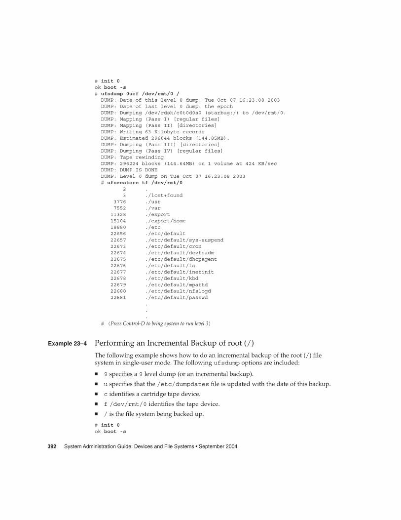
# init 0ok boot -s# ufsdump 0ucf /dev/rmt/0 /DUMP: Date of this level 0 dump: Tue Oct 07 16:23:08 2003DUMP: Date of last level 0 dump: the epochDUMP: Dumping /dev/rdsk/c0t0d0s0 (starbug:/) to /dev/rmt/0.DUMP: Mapping (Pass I) [regular files]DUMP: Mapping (Pass II) [directories]DUMP: Writing 63 Kilobyte recordsDUMP: Estimated 296644 blocks (144.85MB).DUMP: Dumping (Pass III) [directories]DUMP: Dumping (Pass IV) [regular files]DUMP: Tape rewindingDUMP: 296224 blocks (144.64MB) on 1 volume at 424 KB/secDUMP: DUMP IS DONEDUMP: Level 0 dump on Tue Oct 07 16:23:08 2003# ufsrestore tf /dev/rmt/0
2 .3 ./lost+found
3776 ./usr7552 ./var11328 ./export15104 ./export/home18880 ./etc22656 ./etc/default22657 ./etc/default/sys-suspend22673 ./etc/default/cron22674 ./etc/default/devfsadm22675 ./etc/default/dhcpagent22676 ./etc/default/fs22677 ./etc/default/inetinit22678 ./etc/default/kbd22679 ./etc/default/mpathd22680 ./etc/default/nfslogd22681 ./etc/default/passwd
.
.
.
# (Press Control-D to bring system to run level 3)
Performing an Incremental Backup of root (/)The following example shows how to do an incremental backup of the root (/) filesystem in single-user mode. The following ufsdump options are included:
� 9 specifies a 9 level dump (or an incremental backup).� u specifies that the /etc/dumpdates file is updated with the date of this backup.� c identifies a cartridge tape device.� f /dev/rmt/0 identifies the tape device.� / is the file system being backed up.
# init 0ok boot -s
Example 23–4
392 System Administration Guide: Devices and File Systems • September 2004

.
.
.Rebooting with command: boot -sSunOS Release 5.9 Generic May 2002Copyright 1983-2003 Sun Microsystems, Inc. All rights reserved....# ufsdump 9ucf /dev/rmt/0 /DUMP: Date of this level 9 dump: Mon Oct 06 12:36:10 2003DUMP: Date of last level 0 dump: Wed Oct 08 10:12:13 2003DUMP: Dumping /dev/rdsk/c0t0d0s0 (starbug:/) to /dev/rmt/0.DUMP: Mapping (Pass I) [regular files]DUMP: Mapping (Pass II) [directories]DUMP: Writing 63 Kilobyte recordsDUMP: Estimated 335844 blocks (163.99MB).DUMP: Dumping (Pass III) [directories]DUMP: Dumping (Pass IV) [regular files]DUMP: 335410 blocks (163.77MB) on 1 volume at 893 KB/secDUMP: DUMP IS DONEDUMP: Level 9 dump on Mon Oct 06 12:36:10 2003# ufsrestore tf /dev/rmt/0
2 .3 ./lost+found
5696 ./usr11392 ./var17088 ./export22784 ./export/home28480 ./opt5697 ./etc11393 ./etc/default11394 ./etc/default/sys-suspend11429 ./etc/default/cron11430 ./etc/default/devfsadm11431 ./etc/default/dhcpagent11432 ./etc/default/fs11433 ./etc/default/inetinit11434 ./etc/default/kbd11435 ./etc/default/nfslogd11436 ./etc/default/passwd11437 ./etc/default/tar
.
.
.
Performing a Full Backup of a Home Directory
The following example shows how to do a full backup of the/export/home/kryten home directory. The following ufsdump options areincluded:
� 0 specifies that this is a 0 level dump (or a full backup)
� u specifies that the /etc/dumpdates file is updated with the date of this backup
Example 23–5
Chapter 23 • Backing Up Files and File Systems (Tasks) 393

� c identifies a cartridge tape device� f /dev/rmt/0 identifies the tape device� /export/home/kryten is the directory being backed up
# umount /export/home
# ufsdump 0ucf /dev/rmt/0 /export/home/krytenDUMP: Date of this level 0 dump: Tue Oct 07 08:41:41 2003DUMP: Date of last level 0 dump: the epochDUMP: Dumping /dev/rdsk/c0t0d0s0 (starbug:/) to /dev/rmt/0.DUMP: Mapping (Pass I) [regular files]DUMP: Mapping (Pass II) [directories]DUMP: Writing 63 Kilobyte recordsDUMP: Estimated 470 blocks (235KB).DUMP: Dumping (Pass III) [directories]DUMP: Dumping (Pass IV) [regular files]DUMP: 376 blocks (188KB) on 1 volume at 1205 KB/secDUMP: DUMP IS DONE
# ufsrestore tf /dev/rmt/02 .5 ./export6 ./export/home
80799 ./export/home/kryten80800 ./export/home/kryten/filea80801 ./export/home/kryten/fileb80802 ./export/home/kryten/filec80803 ./export/home/kryten/letters80804 ./export/home/kryten/letters/letter180805 ./export/home/kryten/letters/letter280806 ./export/home/kryten/letters/letter380807 ./export/home/kryten/reports80808 ./export/home/kryten/reports/reportA80809 ./export/home/kryten/reports/reportB80810 ./export/home/kryten/reports/reportC
#
Performing a Full Backup to a Remote System (Solaris 9 Data toSolaris 9 System)The following example shows how to do a full backup of a local /export/home filesystem on a Solaris 9 system (starbug) to a tape device on a remote Solaris 9 system(earth) in single-user mode. The following ufsdump options are included:
� 0 specifies a 0 level dump (or a full backup).� u specifies that the /etc/dumpdates file is updated with the date of this backup.� c identifies a cartridge tape device.� f earth:/dev/rmt/0 identifies the remote system name and tape device� /export/home is the file system being backed up.
# ufsdump 0ucf earth:/dev/rmt/0 /export/homeDUMP: Date of this level 0 dump: Mon Oct 06 12:46:50 2003DUMP: Date of last level 0 dump: the epoch
Example 23–6
394 System Administration Guide: Devices and File Systems • September 2004

DUMP: Dumping /dev/rdsk/c0t0d0s7 (starbug:/export/home) toearth:/dev/rmt/0.DUMP: Mapping (Pass I) [regular files]DUMP: Mapping (Pass II) [directories]DUMP: Writing 63 Kilobyte recordsDUMP: Estimated 410 blocks (205KB).DUMP: Dumping (Pass III) [directories]DUMP: Dumping (Pass IV) [regular files]DUMP: Tape rewindingDUMP: 376 blocks (188KB) on 1 volume at 546 KB/secDUMP: DUMP IS DONEDUMP: Level 0 dump on Mon Oct 06 12:46:50 2003# ufsrestore tf earth:/dev/rmt/0
2 .3 ./lost+found4 ./kryten5 ./kryten/filea6 ./kryten/fileb7 ./kryten/filec8 ./kryten/letters9 ./kryten/letters/letter110 ./kryten/letters/letter211 ./kryten/letters/letter312 ./kryten/reports
.
.
.
#
Chapter 23 • Backing Up Files and File Systems (Tasks) 395

396 System Administration Guide: Devices and File Systems • September 2004
CHAPTER 24
Using UFS Snapshots (Tasks)
This chapter describes how to create and back up UFS snapshots.
For information on the procedures associated with creating UFS snapshots, see “UsingUFS Snapshots (Task Map)” on page 397.
For overview information about performing backups, see Chapter 22.
Using UFS Snapshots (Task Map)
Task Description For Instructions
1. Create a UFS snapshot Create a read-only copy of a filesystem by using the fssnapcommand.
“How to Create a UFSSnapshot” on page 400
2. Display UFS snapshotinformation
Identify UFS snapshot informationsuch as the raw snapshot device.
“How to Display UFSSnapshot Information”on page 401
3. (Optional) Delete aUFS snapshot
Delete a snapshot that is alreadybacked up or no longer needed.
“How to Delete a UFSSnapshot” on page 402
4. Back up a UFSsnapshot
Choose one of the following backupmethods:
Create a full backup of a UFS snapshotby using the ufsdump command.
“How to Create a FullBackup of a UFS Snapshot(ufsdump)” on page 403
397

Task Description For Instructions
Create an incremental backup of a UFSsnapshot by using the ufsdumpcommand.
“How to Create anIncremental Backup of aUFS Snapshot (ufsdump)”on page 404
Back up a UFS snapshot by using thetar command.
“How to Back Up a UFSSnapshot (tar)” on page404
5. (Optional) Restoredata from a UFSsnapshot
Restore the UFS snapshot the sameway as you would restore data byusing the ufsrestore command.
“How to Restore aComplete File System”on page 415
UFS Snapshots OverviewThe Solaris release includes the fssnap command for backing up file systems whilethe file system is mounted. You can use the fssnap command to create a read-onlysnapshot of a file system. A snapshot is a file system’s temporary image that is intendedfor backup operations.
When the fssnap command is run, it creates a virtual device and a backing-store file.You can back up the virtual device, which looks and acts like a real device, with any ofthe existing Solaris backup commands. The backing-store file is a bitmap file thatcontains copies of presnapshot data that has been modified since the snapshot wastaken.
Why Use UFS Snapshots?The UFS snapshots feature enables you to keep the file system mounted and thesystem in multiuser mode during backups. Previously, you were advised to bring thesystem to single-user mode to keep the file system inactive when you used theufsdump command to perform backups. You can also use additional Solaris backupcommands, such as tar and cpio, to back up a UFS snapshot for more reliablebackups.
The fssnap command gives administrators of nonenterprise-level systems the powerof enterprise-level tools, such as Sun StorEdge™ Instant Image, without the largestorage demands.
398 System Administration Guide: Devices and File Systems • September 2004

The UFS snapshots feature is similar to the Instant Image product. Although UFSsnapshots can make copies of large file systems, Instant Image is better suited forenterprise-level systems. UFS snapshots is better suited for smaller systems. InstantImage allocates space equal to the size of the entire file system that is being captured.However, the backing-store file that is created by UFS snapshots occupies only asmuch disk space as needed.
This table describes specific differences between UFS snapshots and Instant Image.
UFS Snapshots Sun StorEdge Instant Image
Size of the backing-store file depends on howmuch data has changed since the snapshotwas taken
Size of the backing-store file equivalent equalsthe size of the entire file system being copied
Does not persist across system reboots Persists across system reboots
Works on UFS file systems Cannot be used with root (/) or /usr filesystems
Available starting with the Solaris 8 1/01release
Part of Sun StorEdge products
UFS Snapshots Performance IssuesWhen the UFS snapshot is first created, users of the file system might notice a slightpause. The length of the pause increases with the size of the file system to be captured.While the snapshot is active, users of the file system might notice a slight performanceimpact when the file system is written to, but they see no impact when the file systemis read.
Creating and Deleting UFS SnapshotsWhen you use the fssnap command to create a UFS snapshot, observe how muchdisk space the backing-store file consumes. The backing-store file uses no space, andthen it grows quickly, especially on heavily used systems. Make sure that thebacking-store file has enough space to expand. Or, limit its size with the-o maxsize=n [k,m,g] option, where n [k,m,g] is the maximum size of thebacking-store file.
Chapter 24 • Using UFS Snapshots (Tasks) 399
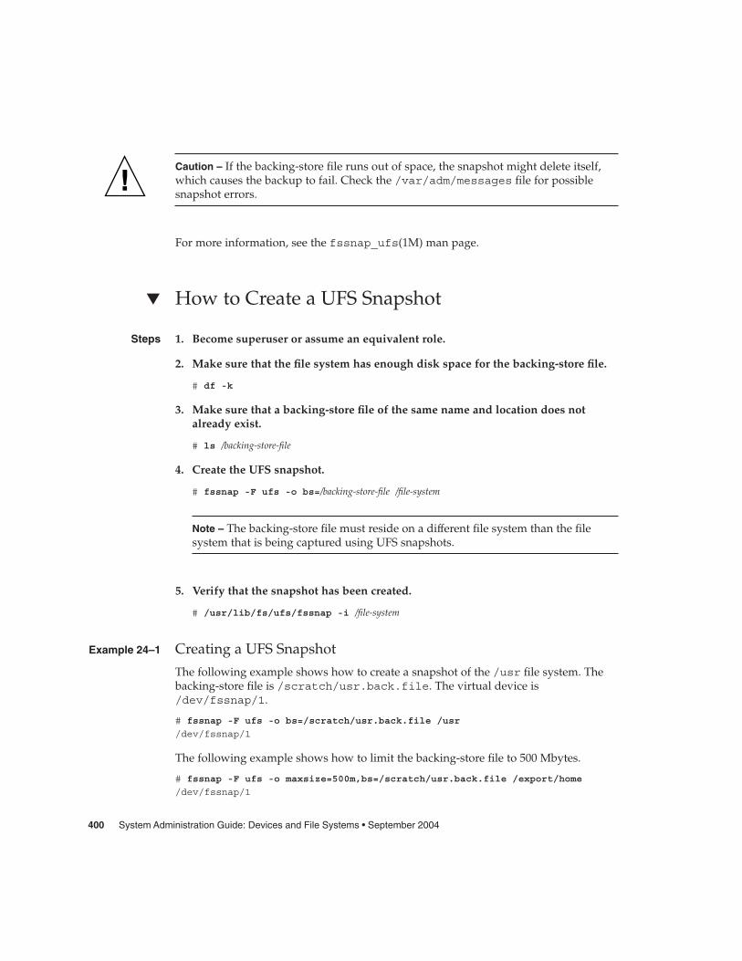
Caution – If the backing-store file runs out of space, the snapshot might delete itself,which causes the backup to fail. Check the /var/adm/messages file for possiblesnapshot errors.
For more information, see the fssnap_ufs(1M) man page.
� How to Create a UFS Snapshot
1. Become superuser or assume an equivalent role.
2. Make sure that the file system has enough disk space for the backing-store file.
# df -k
3. Make sure that a backing-store file of the same name and location does notalready exist.
# ls /backing-store-file
4. Create the UFS snapshot.
# fssnap -F ufs -o bs=/backing-store-file /file-system
Note – The backing-store file must reside on a different file system than the filesystem that is being captured using UFS snapshots.
5. Verify that the snapshot has been created.
# /usr/lib/fs/ufs/fssnap -i /file-system
Creating a UFS Snapshot
The following example shows how to create a snapshot of the /usr file system. Thebacking-store file is /scratch/usr.back.file. The virtual device is/dev/fssnap/1.
# fssnap -F ufs -o bs=/scratch/usr.back.file /usr
/dev/fssnap/1
The following example shows how to limit the backing-store file to 500 Mbytes.
# fssnap -F ufs -o maxsize=500m,bs=/scratch/usr.back.file /export/home
/dev/fssnap/1
Steps
Example 24–1
400 System Administration Guide: Devices and File Systems • September 2004

� How to Display UFS Snapshot InformationYou can display the current snapshots on the system by using the fssnap -i option.If you specify a file system, you see detailed information about that snapshot. If youdon’t specify a file system, you see information about all of the current UFS snapshotsand their corresponding virtual devices.
Note – Use the UFS file system-specific fssnap command to view the extendedsnapshot information as shown in the following examples.
1. Become superuser or assume an equivalent role.
2. List all current snapshots:
For example:
# /usr/lib/fs/ufs/fssnap -iSnapshot number : 0Block Device : /dev/fssnap/0Raw Device : /dev/rfssnap/0Mount point : /usrDevice state : idleBacking store path : /var/tmp/snapshot3Backing store size : 256 KBMaximum backing store size : UnlimitedSnapshot create time : Wed Oct 08 10:38:25 2003Copy-on-write granularity : 32 KBSnapshot number : 1Block Device : /dev/fssnap/1Raw Device : /dev/rfssnap/1Mount point : /Device state : idleBacking store path : /tmp/bs.homeBacking store size : 448 KBMaximum backing store size : UnlimitedSnapshot create time : Wed Oct 08 10:39:29 2003
Copy-on-write granularity : 32 KB
3. Display detailed information about a specific snapshot:
For example:
# /usr/lib/fs/ufs/fssnap -i /usrSnapshot number : 0Block Device : /dev/fssnap/0Raw Device : /dev/rfssnap/0Mount point : /usrDevice state : idleBacking store path : /var/tmp/snapshot3Backing store size : 256 KBMaximum backing store size : UnlimitedSnapshot create time : Wed Oct 08 10:38:25 2003
Steps
Chapter 24 • Using UFS Snapshots (Tasks) 401

Copy-on-write granularity : 32 KB
Deleting a UFS SnapshotWhen you create a UFS snapshot, you can specify that the backing-store file isunlinked. An unlinked backing-store file is removed after the snapshot is deleted. Ifyou don’t specify the -o unlink option when you create a UFS snapshot, you mustdelete the backing-store file manually.
The backing-store file occupies disk space until the snapshot is deleted, whether youuse the -o unlink option to remove the backing-store file or you delete the filemanually.
� How to Delete a UFS SnapshotYou can delete a snapshot either by rebooting the system or by using the fssnap -dcommand. When you use this command, you must and specify the path of the filesystem that contains the UFS snapshot.
1. Become superuser or assume an equivalent role.
2. Identify the snapshot to be deleted.
# /usr/lib/fs/ufs/fssnap -i
3. Delete the snapshot.
# fssnap -d /file-systemDeleted snapshot 1.
4. (Optional) If you did not use the -o unlink option when you created thesnapshot, manually delete the backing-store file.
# rm /file-system/backing-store-file
Deleting a UFS Snapshot
The following example shows how to delete a snapshot and assumes that the-o unlink option was not used.
# fssnap -i0 / 1 /usr
# fssnap -d /usrDeleted snapshot 1.
# rm /scratch/usr.back.file
Steps
Example 24–2
402 System Administration Guide: Devices and File Systems • September 2004

Backing Up a UFS SnapshotYou can create a full backup or an incremental backup of a UFS snapshot. You can usethe standard Solaris backup commands to back up a UFS snapshot.
The virtual device that contains the UFS snapshot acts as a standard read-only device.So, you can back up the virtual device as if you were backing up a file system device.
If you are using the ufsdump command to back up a UFS snapshot, you can specifythe snapshot name during the backup. See the following procedure for moreinformation.
� How to Create a Full Backup of a UFS Snapshot(ufsdump)
1. Become superuser or assume an equivalent role.
2. Identify the UFS snapshot to be backed up.
# /usr/lib/fs/ufs/fssnap -i /file-system
For example:
# /usr/lib/fs/ufs/fssnap -i /usrSnapshot number : 0Block Device : /dev/fssnap/0Raw Device : /dev/rfssnap/0Mount point : /usrDevice state : idleBacking store path : /var/tmp/snapshot3Backing store size : 256 KBMaximum backing store size : UnlimitedSnapshot create time : Wed Oct 08 10:38:25 2003
Copy-on-write granularity : 32 KB
3. Back up the UFS snapshot.
# ufsdump 0ucf /dev/rmt/0 /snapshot-name
For example:
# ufsdump 0ucf /dev/rmt/0 /dev/rfssnap/1
4. Verify that the snapshot is backed up.
For example:
# ufsrestore tf /dev/rmt/0
Steps
Chapter 24 • Using UFS Snapshots (Tasks) 403

� How to Create an Incremental Backup of a UFSSnapshot (ufsdump)Backing up a UFS snapshot incrementally means that only the files that have beenmodified since the last snapshot are backed up. Use the ufsdump command with thenew N option. This option specifies the file system device name to be inserted into the/etc/dumpdates file for tracking incremental dumps.
The following ufsdump command specifies an embedded fssnap command to createan incremental backup of a file system.
1. Become superuser or assume an equivalent role.
2. Create an incremental backup of a UFS snapshot.
For example:
# ufsdump 1ufN /dev/rmt/0 /dev/rdsk/c0t1d0s0 ‘fssnap -F ufs -o raw,bs=
/export/scratch,unlink /dev/rdsk/c0t1d0s0‘
In this example, the -o raw option is used to display the name of the raw deviceinstead of the block device. By using this option, you make it easier to embed thefssnap command in commands (such as the ufsdump command) that require theraw device instead.
3. Verify that the snapshot is backed up.
# ufsrestore ta /dev/rmt/0
� How to Back Up a UFS Snapshot (tar)If you are using the tar command to back up the snapshot, mount the snapshotbefore backing it up.
1. Become superuser or assume an equivalent role.
2. Create a mount point for the snapshot.
For example:
# mkdir /backups/home.bkup
3. Mount the snapshot.
# mount -F ufs -o ro /dev/fssnap/1 /backups/home.bkup
4. Change to the mounted snapshot directory.
# cd /backups/home.bkup
5. Back up the snapshot with the tar command.
Steps
Steps
404 System Administration Guide: Devices and File Systems • September 2004
# tar cvf /dev/rmt/0 .
Restoring Data From a UFS Snapshot BackupThe backup created from the virtual device is essentially just a backup of what theoriginal file system looked like when the snapshot was taken. When you restore a filesystem from the backup, restore as if you had taken the backup directly from theoriginal file system. Such a restore uses the ufsrestore command. For informationon using the ufsrestore command to restore a file or file system, see Chapter 25.
Chapter 24 • Using UFS Snapshots (Tasks) 405

406 System Administration Guide: Devices and File Systems • September 2004
CHAPTER 25
Restoring Files and File Systems(Tasks)
This chapter describes how to use the ufsrestore command to restore files and filesystems that were backed up by using the ufsdump command.
For information on the procedures associated with restoring files and file systems, see“Restoring Files and File System Backups (Task Map)” on page 407.
For information about other commands you can use to archive, restore, copy, or movefiles and file systems, see Chapter 27.
For information about backing up and restoring file systems, see Chapter 22.
Restoring Files and File System Backups(Task Map)The following task map describes the procedures associated with restoring files andfile systems.
Task Description For Instructions
Prepare to restore filesand file systems
Identify the file systems or files to berestored, the tape device, and how youwill restore them.
“Preparing to Restore Filesand File Systems” on page408
Determine which tapesto use
Refer to your backup tapes to find thedate of the last backup that containsthe file or file system that you need torestore.
“How to Determine WhichTapes to Use” on page 410
407

Task Description For Instructions
Restore files Choose one of the following restoremethods:
Restore files interactively–Use thismethod when you are unsure of thefile names because you can browse themedia contents and select individualfiles and directories.
“How to Restore FilesInteractively” on page 411
Restore files noninteractively–Use thismethod when you already know thefew file names to be restored.
“How to Restore SpecificFiles Noninteractively”on page 413
Restore a file system – Use thismethod when you get a new diskdrive or as part of a recoveryprocedure.
“How to Restore aComplete File System”on page 415
Restore the root (/) or/usr file systems
Restoring the root (/) or /usr filesystems involves booting the systemfrom a local CD or the network.
“How to Restore the root(/) and /usr File Systems”on page 418
Preparing to Restore Files and FileSystemsThe ufsrestore command copies files to disk, relative to the current workingdirectory, from backups that were created by using the ufsdump command. You canuse the ufsrestore command to reload an entire file system hierarchy from a level 0dump and incremental dumps that follow it. You can also use this command to restoreone or more single files from any backup tape. If you run the ufsrestore commandas superuser, files are restored with their original owner, last modification time, andmode (permissions).
Before you start to restore files or file systems, you need to know the following:
� The tapes (or diskettes) you need to restore from� The raw device name on which you want to restore the file system� The type of tape device you will use� The device name (local or remote) for the tape device
408 System Administration Guide: Devices and File Systems • September 2004

Determining the File System NameIf you have properly labeled your backup tapes, you should be able to use the filesystem name (/dev/rdsk/device-name) from the tape label. For more information, see“How to Find File System Names” on page 388.
Determining the Type of Tape Device You NeedYou must use a tape device that is compatible with the backup media to restore thefiles. The format of the backup media determines which drive you must use to restorefiles. For example, if your backup media is 8-mm tape, you must use an 8-mm tapedevice to restore the files.
Determining the Tape Device NameYou might have specified the tape device name (/dev/rmt/n) as part of the backuptape label information. If you are using the same drive to restore a backup tape, youcan use the device name from the label. For more information on media devices anddevice names, see Chapter 28.
Restoring Files and File SystemsWhen you back up files and directories, you save them relative to the file system inwhich they belong. When you restore files and directories, the ufsrestore commandre-creates the file hierarchy in the current working directory.
For example, files backed up from the /export/doc/books directory (where/export is the file system), are saved relative to /export. In other words, the book1file in the books directory is saved as ./doc/books/book1 on the tape. Later on, ifyou restored the ./doc/books/book1 file to the /var/tmp directory, the file wouldbe restored to /var/tmp/doc/books/book1.
When you restore individual files and directories, you should restore them to atemporary location, such as the /var/tmp directory. After you verify the files, you canmove them to their proper locations. However, you can restore individual files anddirectories to their original locations. If you do so, be sure you are not overwritingnewer files with older versions from the backup tape.
To avoid conflicts with other users, you might want to create and change to asubdirectory, such as the/var/tmp/restore file, in which to restore the files.
Chapter 25 • Restoring Files and File Systems (Tasks) 409

If you are restoring a hierarchy, you should restore the files to a temporary directoryon the same file system where the files will reside. Then, you can use the mv commandto move the entire hierarchy where it belongs after it is restored.
Note – Do not restore files in the /tmp directory even temporarily. The /tmp directoryis usually mounted as a TMPFS file system. TMPFS does not support UFS file systemattributes such as ACLs.
� How to Determine Which Tapes to Use
1. Ask the user for the approximate date the files to be restored were last modified.
2. Refer to your backup plan to find the date of the last backup that contains thefile or file system.
To retrieve the most recent version of a file, work backward through theincremental backups from highest to lowest dump level and from most recent toleast recent date, unless the user requests otherwise.
3. (Optional) If you have online archive files, identify the correct media.
# ufsrestore ta archive-name ./path/filename ./path/filename
t Lists each file on the tape.
a Reads the table of contents from the online archive file instead offrom the tape.
archive-name Identifies the online archive file name.
./path/filename Identifies the file name or file names you are looking for on theonline archive. If successful, the ufsrestore command printsout the inode number and file name. If unsuccessful,ufsrestore prints an error message.
For more information, see the ufsrestore(1M) man page.
4. Insert the media that contains the files to be restored in the drive and verify thecorrect media.
# ufsrestore tf /dev/rmt/n ./path/filename ./path/filename
Be sure to use the complete path for each filename. If a file is in the backup, its nameand inode number is listed. Otherwise, a message states that the file is not on thevolume.
5. (Optional) If you have multiple backup files on the same tape, position the tapeat the backup file you want to use.
# ufsrestore tfs /dev/rmt/n tape-number
Steps
410 System Administration Guide: Devices and File Systems • September 2004

Determining Which Tapes to Use
The following example shows how to check if the /etc/passwd file is in the onlinearchive.
# ufsrestore ta /var/tmp/root.archive ./etc/passwd
The following example shows how to verify that the /etc/passwd file is on thebackup tape.
# ufsrestore tf /dev/rmt/0 ./etc/passwd
� How to Restore Files Interactively
1. Become superuser or assume an equivalent role.
2. (Optional) Write-protect the tapes for safety.
3. Insert the volume 1 tape into the tape drive.
4. Change to a directory that will be used to restore the files to temporarily.
# cd /var/tmp
5. Start the interactive restoration.
# ufsrestore if /dev/rmt/n
Some informational messages and the ufsrestore> prompt are displayed.
6. Create a list of files to be restored.
a. List the contents of a directory.
ufsrestore> ls [directory-name]
b. Change to a directory.
ufsrestore> cd directory-name
c. Create a list of files and directories that you want to restore.
ufsrestore> add filenames
d. (Optional) Remove any directory or file from the list of files to be restored, ifnecessary.
ufsrestore> delete filename
7. (Optional) Display the file names as they are being restored.
ufsrestore> verbose
Example 25–1
Steps
Chapter 25 • Restoring Files and File Systems (Tasks) 411

8. Restore the files.
ufsrestore> extract
The ufsrestore command asks you which volume number to use.
9. Type the volume number and press Return. If you have only one volume, type 1and press Return.
Specify next volume #: 1
The files and directories in the list are extracted and restored to the currentworking directory.
10. To maintain the mode of the current directory, enter n at the set owner/modeprompt.
set owner/mode for ‘.’? [yn] n
You must wait while the ufsrestore command performs its final cleanup.
11. Quit the ufsrestore program.
ufsrestore> quit
You then see the shell prompt.
12. Verify the restored files.
a. List the restored files and directories.
# ls -l
A list of files and directories is displayed.
b. Check the list to be sure that all the files and directories you specified in thelist have been restored.
13. Move the files to the proper directories.
Restoring Files Interactively
The following example shows how to extract the /etc/passwd and /etc/shadowfiles from the backup tape.
# cd /var/tmp# ufsrestore if /dev/rmt/0ufsrestore> ls.:.cpr_config etc/ lost+found/ sbin/TT_DB/ export/ mnt/ tmp/b/ home/ net/ usrbin kernel/ opt/ var/dev/ lib platform/ vol/devices/ license/ proc/ufsrestore> cd etc
Example 25–2
412 System Administration Guide: Devices and File Systems • September 2004

ufsrestore> add passwd shadowufsrestore> verboseverbose mode onufsrestore> extractExtract requested filesYou have not read any volumes yet.Unless you know which volume your file(s) are on you should startwith the last volume and work towards the first.Specify next volume #: 1extract file ./etc/shadowextract file ./etc/passwdAdd linksSet directory mode, owner, and times.set owner/mode for ‘.’? [yn] nufsrestore> quit
#
� How to Restore Specific Files Noninteractively
1. Become superuser or assume an equivalent role.
2. (Optional) Write-protect the tape for safety.
3. Insert the volume 1 tape into the tape drive.
4. Change to a directory that will be used to restore files to temporarily.
# cd /var/tmp
5. Restore the file or files.
# ufsrestore xvf /dev/rmt/n filename
x Tells ufsrestore to copy specific files or directories in thefilename argument.
v Displays the file names as they are restored.
f /dev/rmt/n Identifies the tape device name.
filename Specifies one or more file names or directory names, separatedby spaces. For example: ./export/home/user1/mail./export/home/user2/mail.
6. Type the volume number where files are located. Press Return.
Specify next volume #: 1
The file or files are restored to the current working directory.
Steps
Chapter 25 • Restoring Files and File Systems (Tasks) 413
7. To maintain the mode of the current directory, type n and press Return at the setowner/mode prompt.
set owner/mode for ’.’? [yn] n
8. Verify the restored files.
a. List the restored files and directories.
# ls -l
A list of files and directories is displayed.
b. Check the list to be sure that all the files and directories you specified in thelist have been restored.
9. Move the files to the proper directories.
Restoring Specific Files Noninteractively
The following example shows how to noninteractively restore the passwd andshadow files to the /var/tmp directory.
# cd /var/tmp# ufsrestore xvf /dev/rmt/0 ./etc/passwd ./etc/shadowVerify volume and initialize mapsMedia block size is 126Dump date: Mon Oct 06 12:36:10 2003Dumped from: the epochLevel 9 dump of / on starbug:/dev/dsk/c0t0d0s0Label: noneExtract directories from tapeInitialize symbol table.Make node ./etcExtract requested filesYou have not read any volumes yet.Unless you know which volume your file(s) are on you should startwith the last volume and work towards the first.Specify next volume #:1extract file ./etc/passwdextract file ./etc/shadowAdd linksSet directory mode, owner, and times.set owner/mode for ‘.’? [yn] n# cd etc# mv passwd /etc# mv shadow /etc
# ls -l /etc
Example 25–3
414 System Administration Guide: Devices and File Systems • September 2004
Restoring Files From a Remote Tape Device
You can restore files from a remote tape drive by adding remote-host: to the front ofthe tape device name, when using the ufsrestore command.
The following example shows how to restore files by using a remote tape drive/dev/rmt/0 on the system venus.
# ufsrestore xf venus:/dev/rmt/0 ./etc/hosts
� How to Restore a Complete File SystemOccasionally, a file system becomes so damaged that you must completely restore it.Typically, you need to restore a complete file system after a disk failure. You mightneed to replace the hardware before you can restore the software. For information onhow to replace a disk, see Chapter 12 or Chapter 13.
Full restoration of a file system such as /export/home can take a lot of time. If youhave consistently backed up file systems, you can restore them to their state from thetime of the last incremental backup.
Note – You cannot use this procedure to restore the root (/) or /usr file systems. Forinstructions on restoring these file systems, see “How to Restore the root (/) and /usrFile Systems” on page 418.
1. Become superuser or assume an equivalent role.
2. If necessary, unmount the file system.
# umount /dev/rdsk/device-name
Or:
# umount /file-system
3. Create the new file system.
# newfs /dev/rdsk/device-name
You are asked if you want to construct a new file system on the raw device. Verifythat the device-name is correct so that you don’t destroy the wrong file system.
For more information, see the newfs(1M) man page.
4. Confirm that the new file system should be created.
newfs: construct a new file system /dev/rdsk/cwtxdysz:(y/n)? y
The new file system is created.
Example 25–4
Steps
Chapter 25 • Restoring Files and File Systems (Tasks) 415
5. Mount the new file system on a temporary mount point.
# mount /dev/dsk/device-name /mnt
6. Change to the mount point directory.
# cd /mnt
7. (Optional) Write-protect the tapes for safety.
8. Insert the first volume of the level 0 tape into the tape drive.
9. Restore the files.
# ufsrestore rvf /dev/rmt/n
The dump level 0 backup is restored. If the backup required multiple tapes, you areprompted to load each tape in numeric order.
10. Remove the tape and load the next level tape in the drive.
Always restore tapes starting with dump level 0 and continuing until you reach thehighest dump level.
11. Repeat Step 8 through Step 10 for each dump level, from the lowest to thehighest level.
12. Verify that the file system is restored.
# ls
13. Remove the restoresymtable file.
# rm restoresymtable
The restoresymtable file that is created and used by the ufsrestorecommand to check-point the restore is removed.
14. Change to another directory.
# cd /
15. Unmount the newly restored file system.
# umount /mnt
16. Remove the last tape and insert a new tape that is not write-protected in the tapedrive.
17. Make a level 0 backup of the newly restored file system.
# ufsdump 0ucf /dev/rmt/n /dev/rdsk/device-name
A level 0 backup is performed. Always immediately do a full backup of a newlycreated file system because the ufsrestore command repositions the files andchanges the inode allocation.
416 System Administration Guide: Devices and File Systems • September 2004

18. Mount the restored file system.
# mount /dev/dsk/device-name mount-point
The restored file system is mounted and available for use.
19. Verify that the restored and mounted file system is available.
# ls mount-point
Restoring a Complete File System
The following example shows how to restore the /export/home file system.
# umount /export/home# newfs /dev/rdsk/c0t0d0s7newfs: /dev/rdsk/c0t0d0s7 last mounted as /export/homenewfs: construct a new file system /dev/rdsk/c0t0d0s7: (y/n)? y819314 sectors in 867 cylinders of 15 tracks, 63 sectors
400.1MB in 55 cyl groups (16 c/g, 7.38MB/g, 3584 i/g)super-block backups (for fsck -F ufs -o b=#) at:32, 15216, 30400, 45584, 60768, 75952, 91136, 106320, 121504, 136688,681264, 696448, 711632, 725792, 740976, 756160, 771344, 786528, 801712,816896,Verify volume and initialize mapsMedia block size is 126Dump date: Tue Oct 07 08:41:41 2003Dumped from: the epochLevel 0 dump of a partial file system on starbug:/export/home/krytenLabel: noneBegin level 0 restoreInitialize symbol table.Extract directories from tapeCalculate extraction list.Extract new leaves.Check pointing the restoreextract file ./export/home/kryten/fileaextract file ./export/home/kryten/filebextract file ./export/home/kryten/filecextract file ./export/home/kryten/letters/letter1extract file ./export/home/kryten/letters/letter2extract file ./export/home/kryten/letters/letter3extract file ./export/home/kryten/reports/reportAextract file ./export/home/kryten/reports/reportBextract file ./export/home/kryten/reports/reportCAdd linksSet directory mode, owner, and times.Check the symbol table.Check pointing the restore# mount /dev/dsk/c0t0d0s7 /mnt# cd /mnt# ufsrestore rvf /dev/rmt/0# ls# rm restoresymtable
Example 25–5
Chapter 25 • Restoring Files and File Systems (Tasks) 417

# cd /# umount /mnt# ufsdump 0ucf /dev/rmt/0 /export/home
.
.
.# mount /dev/dsk/c0t3d0s7 /export/home
# ls /export/home
� How to Restore the root (/) and /usr File Systems
1. Become superuser or assume an equivalent role.
2. Add a new system disk to the system where the root (/) and /usr file systemswill be restored.
For a detailed description about adding a system disk, refer to Chapter 12 orChapter 13.
3. Mount the new file system on a temporary mount point.
# mount /dev/dsk/device-name /mnt
4. Change to the /mnt directory.
# cd /mnt
5. (Optional) Write-protect the tapes for safety.
6. Create the links for the tape device.
# tapes
7. Restore the root file system.
# ufsrestore rvf /dev/rmt/n
The dump level 0 tape is restored.
8. Remove the tape and load the next level tape in the drive.
Always restore tapes starting with dump level 0 and continuing from the lowest tohighest dump level.
9. Continue restoring as needed.
# ufsrestore rvf /dev/rmt/n
The next level tape is restored.
10. Repeat Step 8 and Step 9 for each additional tape.
Steps
418 System Administration Guide: Devices and File Systems • September 2004
11. Verify that the file system is restored.
# ls
12. Remove the restoresymtable file.
# rm restoresymtable
The restoresymtable file that is created and used by the ufsrestorecommand to check-point the restore is removed.
13. Change to the root (/) directory.
# cd /
14. Unmount the newly created file system.
# umount /mnt
15. Check the new file system.
# fsck /dev/rdsk/device-name
The restored file system is checked for consistency.
16. Create the boot blocks on the root partition.
# installboot /usr/platform/‘uname-i‘/lib/fs/ufs/bootblk
/dev/rdsk/device-name
For more information, see theinstallboot(1M) man page.
For an example of using the installboot command on a SPARC based system,see Example 25–6. For an example of using the installboot command on an x86based system, see Example 25–7.
17. Insert a new tape in the tape drive.
18. Back up the new file system.
# ufsdump 0uf /dev/rmt/n /dev/rdsk/device-name
A dump level 0 backup is performed. Always immediately do a full backup of anewly created file system because the ufsrestore command repositions the filesand changes the inode allocation.
19. Repeat steps 5 through 16 for the /usr file system, if necessary.
20. Reboot the system.
# init 6
The system is rebooted.
Chapter 25 • Restoring Files and File Systems (Tasks) 419

SPARC: Restoring the root (/) File System
This example shows how to restore the root (/) file system on a SPARC system. Thisexample assumes that the system is booted from a local CD or from the network.
# mount /dev/dsk/c0t3d0s0 /mnt# cd /mnt# tapes# ufsrestore rvf /dev/rmt/0# ls# rm restoresymtable# cd /# umount /mnt# fsck /dev/rdsk/c0t3d0s0# installboot /usr/platform/sun4u/lib/fs/ufs/bootblk /dev/rdsk/c0t3d0s0# ufsdump 0uf /dev/rmt/0 /dev/rdsk/c0t3d0s0
# init 6
x86: Restoring the root (/) File System
This example shows how to restore the root (/) file system on an x86 system. Thisexample assumes that the system is booted from a local CD or from the network.
# mount /dev/dsk/c0t3d0s0 /mnt# cd /mnt# tapes# ufsrestore rvf /dev/rmt/0# ls# rm restoresymtable# cd /# umount /mnt# fsck /dev/rdsk/c0t3d0s0# installboot /usr/platform/‘uname -i‘/lib/fs/ufs/pboot /usr/platform/‘uname -i‘/lib/fs/ufs/bootblk /dev/rdsk/c0t3d0s2# ufsdump 0uf /dev/rmt/0 /dev/rdsk/c0t3d0s0
# init 6
Example 25–6
Example 25–7
420 System Administration Guide: Devices and File Systems • September 2004

CHAPTER 26
UFS Backup and Restore Commands(Reference)
This chapter contains reference information on the ufsdump and ufsrestorecommands.
This is a list of information in this chapter.
� “How the ufsdump Command Works” on page 421� “Options and Arguments for the ufsdump Command” on page 426� “The ufsdump Command and Security Issues” on page 428� “Options and Arguments for the ufsrestore Command” on page 429
For overview information about performing backups, see Chapter 22.
For information about backup tasks, see Chapter 23.
How the ufsdump Command WorksThe ufsdump command makes two passes when it backs up a file system. On the firstpass, this command scans the raw device file for the file system and builds a table ofdirectories and files in memory. Then, this command writes the table to the backupmedia. In the second pass, the ufsdump command goes through the inodes innumerical order, reading the file contents and writing the data to the backup media.
Determining Device CharacteristicsThe ufsdump command needs to know only an appropriate tape block size and howto detect the end of media.
421
Detecting the End of MediaThe ufsdump command writes a sequence of fixed-size records. When the ufsdumpcommand receives notification that a record was only partially written, it assumes thatit has reached the physical end of the media. This method works for most devices. If adevice is not able to notify the ufsdump command that only a partial record has beenwritten, a media error occurs as the ufsdump command tries to write another record.
Note – DAT devices and 8-mm tape devices detect end-of-media. Cartridge tapedevices and 1/2–inch tape devices do not detect end-of-media.
The ufsdump command automatically detects the end-of-media for most devices.Therefore, you do not usually need to use the -c, -d, -s, and -t options to performmultivolume backups.
The only times you need to use the end-of-media options are under the followingconditions:
� The ufsdump command does not understand the way the device detects theend-of-media.
� You are going to restore the files on a SunOS 4. 1 system with the restorecommand.
To ensure compatibility with the restore command, the size option can still force theufsdump command to go to the next tape or diskette before reaching the end of thecurrent tape or diskette.
Copying Data With the ufsdump CommandThe ufsdump command copies data only from the raw disk slice. If the file system isstill active, any data in memory buffers is probably not copied. The backup done bythe ufsdump command does not copy free blocks, nor does it make an image of thedisk slice. If symbolic links point to files on other slices, the link itself is copied.
Purpose of the /etc/dumpdates FileThe ufsdump command, when used with the -u option, maintains and updates the/etc/dumpdates file. Each line in the /etc/dumpdates file shows the followinginformation:
� The file system backed up� The dump level of the last backup� The day, date, and time of the backup
422 System Administration Guide: Devices and File Systems • September 2004

For example:
/dev/rdsk/c0t0d0s7 0 Wed Oct 8 10:30:52 2003/dev/rdsk/c0t0d0s0 0 Tue Oct 6 10:12:13 2003
/dev/rdsk/c0t0d0s0 9 Wed Oct 8 10:26:14 2003
When you do an incremental backup, the ufsdump command checks the/etc/dumpdates file to find the date of the most recent backup of the next lowerdump level. Then, this command copies to the media all files that were modified sincethe date of that lower-level backup. After the backup is complete, a new informationline, which describes the backup you just completed, replaces the information line forthe previous backup at that level.
Use the /etc/dumpdates file to verify that backups are being done. This verificationis particularly important if you are having equipment problems. If a backup cannot becompleted because of equipment failure, the backup is not recorded in the/etc/dumpdates file.
If you need to restore an entire disk, check the /etc/dumpdates file for a list of themost recent dates and levels of backups so that you can determine which tapes youneed to restore the entire file system.
Note – The /etc/dumpdates file is a text file that can be edited. However, edit it onlyat your own risk. If you make changes to the file that do not match your archive tapes,you might be unable to find the tapes (or files) you need.
Backup Device (dump-file) ArgumentThe dump-file argument (to the -f option) specifies the destination of the backup. Thedestination can be one of the following:
� Local tape drive� Local diskette drive� Remote tape drive� Remote diskette drive� Standard output
Use this argument when the destination is not the default local tape drive/dev/rmt/0. If you use the -f option, then you must specify a value for thedump-fileargument.
Note – The dump-file argument can also point to a file on a local disk or on a remotedisk. If done by mistake, this usage can fill up a file system.
Chapter 26 • UFS Backup and Restore Commands (Reference) 423

Local Tape or Diskette DriveTypically, the dump-file argument specifies a raw device file for a tape device ordiskette. When the ufsdump command writes to an output device, it creates a singlebackup file that might span multiple tapes or diskettes.
You specify a tape device or a diskette on your system by using a device abbreviation.The first device is always 0. For example, if you have a SCSI tape controller and oneQIC-24 tape drive that uses medium-density formatting, use this device name:
/dev/rmt/0m
When you specify a tape device name, you can also type the letter “n” at the end ofthe name to indicate that the tape drive should not rewind after the backup iscompleted. For example:
/dev/rmt/0mn
Use the “no-rewind” option if you want to put more than one file onto the tape. If yourun out of space during a backup, the tape does not rewind before the ufsdumpcommand asks for a new tape. For a complete description of device namingconventions, see “Backup Device Names” on page 456.
Remote Tape or Diskette DriveYou specify a remote tape device or a remote diskette by using the syntax host:device.The ufsdump command writes to the remote device when superuser on the localsystem has access to the remote system. If you usually run the ufsdump command assuperuser, the name of the local system must be included in the /.rhosts file on theremote system. If you specify the device as user@host:device, the ufsdump commandtries to access the device on the remote system as the specified user. In this case, thespecified user must be included in the /.rhosts file on the remote system.
Use the naming convention for the device that matches the operating system for thesystem on which the device resides, not the system from which you run the ufsdumpcommand. If the drive is on a system that is running a previous SunOS release (forexample, 4.1.1), use the SunOS 4.1 device name (for example, /dev/rst0). If thesystem is running Solaris software, use the SunOS 5.9 convention (for example,/dev/rmt/0).
Using Standard Output With the ufsdump CommandWhen you specify a dash (-) as the dump-file argument, the ufsdump command writesto standard output.
424 System Administration Guide: Devices and File Systems • September 2004

Note – The -v option (verify) does not work when the dump-file argument is standardoutput.
You can use the ufsdump and ufsrestore commands in a pipeline to copy a filesystem by writing to standard output with the ufsdump command and reading fromstandard input with the ufsrestore command. For example:
# ufsdump 0f - /dev/rdsk/c0t0d0s7 | (cd /home; ufsrestore xf -)
Specifying Files to Back UpYou must always include filenames as the last argument on the command line. Thisargument specifies the source or contents of the backup.
For a file system, specify the raw device file as follows:
/dev/rdsk/c0t0d0s6
You can specify the file system by its mount point directory (for example,/export/home), as long as an entry for it exists in the /etc/vfstab file.
For a complete description of device– naming conventions, see “Backup DeviceNames” on page 456.
For individual files or directories, type one or more names separated by spaces.
Note – When you use the ufsdump command to back up one or more directories orfiles (rather than a complete file system), a level 0 backup is done. Incrementalbackups do not apply.
Specifying Tape CharacteristicsIf you do not specify any tape characteristics, the ufsdump command uses a set ofdefaults. You can specify the tape cartridge (c), density (d), size (s), and number oftracks (t). Note that you can specify the options in any order, as long as the argumentsthat follow match the order of the options.
Limitations of the ufsdump CommandThe ufsdump command cannot do the following:
Chapter 26 • UFS Backup and Restore Commands (Reference) 425
� Automatically calculate the number of tapes or diskettes that are needed forbacking up file systems. You can use the dry run mode (S option) to determinehow much space is needed before actually backing up file systems.
� Provide built-in error checking to minimize problems when it backs up an activefile system.
� Back up files that are remotely mounted from a server. Files on the server must bebacked up on the server itself. Users are denied permission to run the ufsdumpcommand on files they own that are located on a server.
Options and Arguments for theufsdump CommandThis section describes in detail the options and arguments for the ufsdump command.The syntax for the ufsdump command is as follows:
/usr/sbin/ufsdump options arguments filenames
options Is a single string of one-letter option names.
arguments Identifies option arguments and might consist of multiple strings. Theoption letters and their associated arguments must be in the same order.
filenames Identifies the files to back up. These arguments must always come last,each separated by a space.
Default ufsdump OptionsIf you run the ufsdump command without any options, use this syntax:
# ufsdump filenames
The ufsdump command uses these options and arguments, by default:
ufsdump 9uf /dev/rmt/0 filenames
These options do a level 9 incremental backup to the default tape drive at its preferreddensity.
Options for the ufsdump CommandThe following table describes the options for the ufsdump command.
426 System Administration Guide: Devices and File Systems • September 2004

TABLE 26–1 Options for the ufsdump Command
Option Description
0–9 Dump level. Level 0 is for a full backup of the complete filesystem or file systems specified by filenames. Levels 1–9 are forincremental backups of files that have changed since the lastlower-level backup.
a archive-file Archive file. Specifies a file that stores (archives) a backup table ofcontents. The file can be understood only by the ufsrestorecommand. This command uses the table of contents to determinewhether a file to be restored is present in a backup file, and if so,on which volume of the media the file resides.
b factor Blocking factor. Specifies the number of 512-byte blocks to writeto tape at a time.
c Cartridge. Identifies the backup media as cartridge tape. Whenend-of-media detection applies, this option sets the block size to126.
d bpi Tape density. Specifies the tape density. Use this option only whenthe ufsdump command cannot detect the end of the media.
D Diskette. Identifies the backup media as a diskette.
f dump-file Dump file. Writes the files to the destination that is specified bydump-file instead of the default device. If the file is specified asuser@system:device, the ufsdump command attempts to execute asthe specified user on the remote system. The specified user musthave a /.rhosts file on the remote system that allows the userwho is invoking the command on the local system to access theremote system.
l Autoload. Use this option if you have an autoloading(stackloader) tape drive. When the end of a tape is reached, thisoption takes the drive offline and waits up to two minutes for thetape drive to be ready again. If the drive is ready within twominutes, the autoload continues. If the drive is not ready after twominutes, autoload prompts the operator to load another tape.
n Notify. When intervention is needed, this option sends a messageto all terminals of all users in the sys group.
o Offline. When the command is finished with a tape or diskette,this option takes the drive offline, rewinds (if tape), and if possibleremoves the media. For example, this option ejects a diskette orremoves an 8-mm autoloaded tape.
s size Size. Specifies the size of the backup media. For tapes, the size isspecified in feet. For diskettes, the size is specified by the numberof 1024–byte blocks.. Use this option only when the ufsdumpcommand cannot detect the end of the media.
Chapter 26 • UFS Backup and Restore Commands (Reference) 427
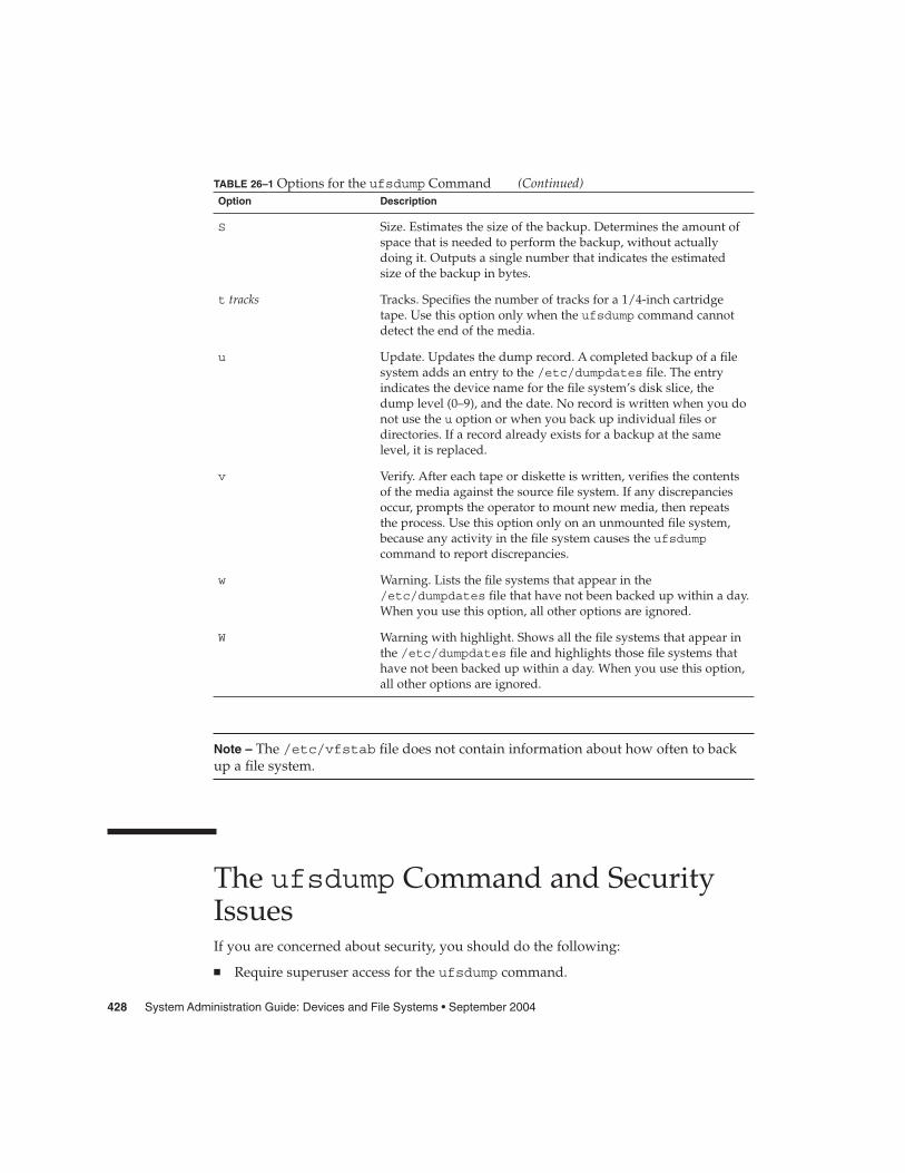
TABLE 26–1 Options for the ufsdump Command (Continued)Option Description
S Size. Estimates the size of the backup. Determines the amount ofspace that is needed to perform the backup, without actuallydoing it. Outputs a single number that indicates the estimatedsize of the backup in bytes.
t tracks Tracks. Specifies the number of tracks for a 1/4-inch cartridgetape. Use this option only when the ufsdump command cannotdetect the end of the media.
u Update. Updates the dump record. A completed backup of a filesystem adds an entry to the /etc/dumpdates file. The entryindicates the device name for the file system’s disk slice, thedump level (0–9), and the date. No record is written when you donot use the u option or when you back up individual files ordirectories. If a record already exists for a backup at the samelevel, it is replaced.
v Verify. After each tape or diskette is written, verifies the contentsof the media against the source file system. If any discrepanciesoccur, prompts the operator to mount new media, then repeatsthe process. Use this option only on an unmounted file system,because any activity in the file system causes the ufsdumpcommand to report discrepancies.
w Warning. Lists the file systems that appear in the/etc/dumpdates file that have not been backed up within a day.When you use this option, all other options are ignored.
W Warning with highlight. Shows all the file systems that appear inthe /etc/dumpdates file and highlights those file systems thathave not been backed up within a day. When you use this option,all other options are ignored.
Note – The /etc/vfstab file does not contain information about how often to backup a file system.
The ufsdump Command and SecurityIssuesIf you are concerned about security, you should do the following:
� Require superuser access for the ufsdump command.
428 System Administration Guide: Devices and File Systems • September 2004

� Ensure superuser access entries are removed from /.rhosts files on clients andservers if you are doing centralized backups.
For general information on security, see System Administration Guide: SecurityServices.
Options and Arguments for theufsrestore CommandThe syntax of the ufsrestore command is as follows:
/usr/sbin/ufsrestore options arguments filenames
options Is a single string of one-letter option names. You must choose one andonly one of these options: i, r, R, t, or x. The additional options listedin Table 26–3 are optional.
arguments Follows the option string with the arguments that match the options.The option letters and their associated arguments must be in the sameorder.
filenames Specifies the file or files to be restored as arguments to the x or toptions. These arguments must always come last, separated by spaces.
You must use one (and only one) of the ufsrestore command options described inthe following table.
TABLE 26–2 One Required Option for the ufsrestore Command
Option Description
i Interactive. Runs the ufsrestore command in interactivemode. In this mode, you can use a limited set of shell-likecommands to browse the contents of the media and selectindividual files or directories to restore. For a list of interactivecommands, see Table 26–4.
r Recursive. Restores the entire contents of the media into thecurrent working directory (which should be the top level of thefile system). Information used to restore incremental backups ontop of the full backup (for example, restoresymtable) is alsoincluded. To completely restore a file system, use this option torestore the full (level 0) backup and each subsequent incrementalbackup. Although this option is intended for a new file system(that was just created with the newfs command), files not on thebackup media are preserved.
Chapter 26 • UFS Backup and Restore Commands (Reference) 429

TABLE 26–2 One Required Option for the ufsrestore Command (Continued)Option Description
R Resume restoring. Prompts for the volume from which to resumerestoring and restarts from a checkpoint. You rerun theufsrestore command with this option after a full restore (roption) is interrupted.
x [filenames] Extract. Selectively restores the files you specify by the filenamesargument. filenames can be a list of files and directories, eachseparated by a space. All files under a specified directory arerestored unless you also use the h option. If you omit filenames orenter “.” for the root directory, all files on all volumes of themedia (or from standard input) are restored. Existing files areoverwritten, and warnings are displayed.
t [filenames] Table of contents. Checks the files that are specified in thefilenames argument against the media. For each file, lists the fullfile name and the inode number (if the file is found) or indicatesthat the file is not on the “volume” (meaning any volume in amultivolume backup). If you do not enter the filenames argument,all files on all volumes of the media are listed (withoutdistinguishing on which volume files are located).
If you also use the h option, only the directory files that arespecified in filenames, not their contents, are checked and listed.The table of contents is read from the first volume of the media,or, if you use the a option, from the specified archive file. Thisoption is mutually exclusive with the x and r options.
Additional ufsrestore options are described in the following table. These optionsare optional.
TABLE 26–3 Additional Options for the ufsrestore Command
Option Description
a archive-file [filenames] Archive file. Takes the backup table of contents from the specifiedarchive-file instead of from the media (first volume). You can usethis option with the t, i, or x options to see if files are on themedia without having to mount any media. If you use this optionwith the x and interactive (i) extract options, you are promptedto mount the appropriate volume before extracting the file orfiles.
b factor Blocking factor. Specifies number of 512-byte blocks read at atime from a tape. By default, the ufsrestore command tries tofigure out the block size that was used when the tape was beingwritten to.
d Debug. Turns on debugging messages.
430 System Administration Guide: Devices and File Systems • September 2004

TABLE 26–3 Additional Options for the ufsrestore Command (Continued)Option Description
f backup-file Backup file. Reads the files from the source indicated bybackup-file, instead of from the default device file /dev/rmt/0m.If you use the f option, you must specify a value for backup-file.When backup-file is of the form system:device, the ufsrestorecommand reads from the remote device. You can also use thebackup-file argument to specify a file on a local or remote disk. Ifthebackup-file consistes of ‘-’, the files are read from standardinput.
h Turns off directory expansion. Only the directory file you specifyis extracted or listed.
m Restores specified files into the current directory on the disk,regardless of where they are located in the backup hierarchy.Also, renames the specified files with their inode number. Forexample, if the current working directory is /files, a file in thebackup named ./dready/fcs/test with inode number 42 isrestored as /files/42. This option is useful only when you areextracting a few files.
s n Skip. Skips to the nth backup file on the media (first volume).This option is useful when you put more than one backup on asingle tape.
v Verbose. Displays the names and inode numbers of each file as itis restored.
y Specifies that the command continues when errors occur whilereading the media, trying to skip over bad blocks instead ofstopping and asking whether to continue. This option tells thecommand to assume a yes response.
The following table describes ufsrestore’s interactive commands.
TABLE 26–4 Commands for Interactive Restore
Option Description
ls [directory-name] Lists the contents of either the current directory or the specifieddirectory. Directories are marked by a / suffix. Entries in thecurrent list to be restored (extracted) are marked by an * prefix.Inode numbers are shown if the verbose option (v) is used.
cd directory-name Changes to the specified directory in the backup hierarchy.
Chapter 26 • UFS Backup and Restore Commands (Reference) 431

TABLE 26–4 Commands for Interactive Restore (Continued)Option Description
add [filename] Adds the current directory or the specified file or directory to thelist of files to extract (restore). If you do not use the h option, allfiles in a specified directory and its subdirectories are added tothe list. All the files you want to restore to a directory might notbe on a single backup tape or diskette. You might need to restorefrom multiple backups at different levels to get the latest versionsof all the files.
delete [filename] Deletes the current directory or the specified file or directoryfrom the list of files to extract (restore). If you do not use the hoption, all files in the specified directory and its subdirectoriesare deleted from the list. The files and directories are deletedonly from the extract list you are building. They are not deletedfrom the media or the file system.
extract Extracts the files in the list and restores them relative to thecurrent working directory on the disk. When you are asked for avolume number for a single-volume backup, specify 1. If you aredoing a multiple tape or multiple diskette restore and restoring asmall number of files, start instead with the last tape or diskette.
help Displays a list of commands that you can use in interactivemode.
pwd Displays the path name of the current working directory in thebackup hierarchy.
q Quits interactive mode without restoring any additional files.
setmodes Lets you set the mode for files to be restored to match the modeof the root directory of the file system from which they werebacked up. You are prompted with: set owner/mode for ’.’[yn]? Type y (for yes) to set the mode (permissions, owner,times) of the current directory to match the root directory of thefile system from which they were backed up. Use this modewhen you restore a complete file system.
Type n (for no) to leave the mode of the current directoryunchanged. Use this mode when you restore part of a backup toa directory other than the directory from which the files werebacked up.
verbose Turns on or off the verbose option (which can also be typed as von the command line outside of interactive mode). Whenverbose is on, the interactive ls command lists inode numbers,and the ufsrestore command displays information on eachfile as it is extracted.
what Displays the backup header from the tape or diskette.
432 System Administration Guide: Devices and File Systems • September 2004

CHAPTER 27
Copying UFS Files and File Systems(Tasks)
This chapter describes how to copy UFS files and file systems to disk, tape, anddiskettes by using various backup commands.
This is a list of the step-by-step instructions in this chapter.
� “How to Copy a Disk (dd)” on page 435� “How to Copy Directories Between File Systems (cpio)” on page 438� “How to Copy Files to a Tape (tar)” on page 441� “How to List the Files on a Tape (tar)” on page 442� “How to Retrieve Files From a Tape (tar)” on page 442� “Copying Files to a Tape With the pax Command” on page 444� “How to Copy All Files in a Directory to a Tape (cpio)” on page 445� “How to List the Files on a Tape (cpio)” on page 446� “How to Retrieve All Files From a Tape (cpio)” on page 447� “How to Retrieve Specific Files From a Tape (cpio)” on page 448� “How to Copy Files to a Remote Tape Device (tar and dd)” on page 449� “How to Extract Files From a Remote Tape Device” on page 450� “How to Copy Files to a Single Formatted Diskette (tar)” on page 452� “How to List the Files on a Diskette (tar)” on page 453� “How to Retrieve Files From a Diskette (tar)” on page 453
Commands for Copying File SystemsWhen you need to back up and restore complete file systems, use the ufsdump andufsrestore commands described in Chapter 26. When you want to copy or moveindividual files, portions of file systems, or complete file systems, you can use theprocedures described in this chapter instead of the ufsdump and ufsrestorecommands.
The following table describes when to use the various backup commands.
433

TABLE 27–1 When to Use Various Backup Commands
Task Command For More Information
Back up file systems to tape ufsdump “How to Backup a File System toTape” on page 390
Create a file system snapshot fssnap Chapter 24
Restore file systems from tape ufsrestore “How to Restore a Complete FileSystem” on page 415
Transport files to other systems pax, tar, or cpio “Copying Files and File Systemsto Tape” on page 439
Copy files or file systemsbetween disks
dd “How to Copy a Disk (dd)”on page 435
Copy files to diskette tar “How to Copy Files to a SingleFormatted Diskette (tar)”on page 452
The following table describes various backup and restore commands.
TABLE 27–2 Summary of Various Backup Commands
Command NameAware of File SystemBoundaries?
Supports MultipleVolume Backups?
Physical or LogicalCopy?
volcopy Yes Yes Physical
tar No No Logical
cpio No Yes Logical
pax Yes Yes Logical
dd Yes No Physical
ufsdump/ufsrestore Yes Yes Logical
The following sections describe the advantages and disadvantages of each command.Also provided are step-by-step instructions and examples of how to use thecommands.
Copying File Systems Between DisksTwo commands are used to copy file systems between disks:
� volcopy� dd
434 System Administration Guide: Devices and File Systems • September 2004
For more information about volcopy, see the volcopy(1M).
The next section describes how to use the dd command to copy file systems betweendisks.
Making a Literal File System CopyThe dd command makes a literal (block-level) copy of a complete UFS file system toanother file system or to a tape. By default, the dd command copies standard input tostandard output.
Note – Do not use the dd command with variable-length tape drives without firstspecifying an appropriate block size.
You can specify a device name in place of standard input or standard output, or both.In this example, the contents of the diskette are copied to a file in the /tmp directory:
$ dd < /floppy/floppy0 > /tmp/output.file2400+0 records in
2400+0 records out
The dd command reports on the number of blocks it reads and writes. The numberafter the + is a count of the partial blocks that were copied. The default block size is512 bytes.
The dd command syntax is different from most other commands. Options are specifiedas keyword=value pairs, where keyword is the option you want to set and value is theargument for that option. For example, you can replace standard input and standardoutput with this syntax:
$ dd if=input-file of=output-file
To use the keyword=value pairs instead of the redirect symbols in the previous example,you would type the following:
$ dd if=/floppy/floppy0 of=/tmp/output.file
� How to Copy a Disk (dd)
1. Make sure that the source disk and destination disk have the same diskgeometry.
2. Become superuser or assume an equivalent role.
3. Create the /reconfigure file so the system will recognize the destination diskto be added when it reboots.
Steps
Chapter 27 • Copying UFS Files and File Systems (Tasks) 435

# touch /reconfigure
4. Shut down the system.
# init 0
5. Attach the destination disk to the system.
6. Boot the system.
ok boot
7. Copy the source disk to the destination disk.
# dd if=/dev/rdsk/device-name of=/dev/rdsk/device-name bs=block-size
if=/dev/rdsk/device-name Represents the overlap slice of the master diskdevice, usually slice 2.
of=/dev/rdsk/device-name Represents the overlap slice of the destinationdisk device, usually slice 2.
bs=blocksize Identifies block size, such as 128 Kbytes or 256Kbytes. A large block size value decreases thetime it takes to copy the disk.
For more information, see the dd(1M)
8. Check the new file system.
# fsck /dev/rdsk/device-name
9. Mount the destination disk’s root (/) file system.
# mount /dev/dsk/device-name /mnt
10. Change to the directory where the /etc/vfstab file is located.
# cd /mnt/etc
11. Using a text editor, edit the destination disk’s /etc/vfstab file to reference thecorrect device names.
For example, change all instances of c0t3d0 to c0t1d0.
12. Change to the destination disk’s root (/) directory.
# cd /
13. Unmount the destination disk’s root (/) file system.
# umount /mnt
14. Shut down the system.
# init 0
436 System Administration Guide: Devices and File Systems • September 2004

15. Boot from the destination disk to single-user mode.
# boot diskn -s
Note – The installboot command is not needed for the destination disk becausethe boot blocks are copied as part of the overlap slice.
16. Unconfigure the destination disk.
# sys-unconfig
The system is shut down after it is unconfigured.
17. Boot from the destination disk again and provide its system information, such ashost name, time zone, and so forth.
# boot diskn
18. After the system is booted, log in as superuser to verify the system information.
hostname console login:
Copying a Disk (dd)
This example shows how to copy the master disk /dev/rdsk/c0t0d0s2 to thedestination disk /dev/rdsk/c0t2d0s2.
# touch /reconfigure# init 0ok boot# dd if=/dev/rdsk/c0t0d0s2 of=/dev/rdsk/c0t2d0s2 bs=128k# fsck /dev/rdsk/c0t2d0s2# mount /dev/dsk/c0t2d0s2 /mnt# cd /mnt/etc# vi vfstab(Modify entries for the new disk)# cd /# umount /mnt# init 0# boot disk2 -s# sys-unconfig
# boot disk2
Example 27–1
Chapter 27 • Copying UFS Files and File Systems (Tasks) 437

Copying Directories Between FileSystems (cpio Command)You can use the cpio (copy in and out) command to copy individual files, groups offiles, or complete file systems. This section describes how to use the cpio command tocopy complete file systems.
The cpio command is an archiving program that copies a list of files into a single,large output file. This command inserts headers between the individual files tofacilitate recovery. You can use the cpio command to copy complete file systems toanother slice, another system, or to a media device, such as a tape or diskette.
Because the cpio command recognizes end-of-media and prompts you to insertanother volume, it is the most effective command, other than ufsdump, to use tocreate archives that require multiple tapes or diskettes.
With the cpio command, you frequently use the ls and find commands to list andselect the files you want to copy, and then to pipe the output to the cpio command.
� How to Copy Directories Between File Systems(cpio)
1. Become superuser or assume an equivalent role.
2. Change to the appropriate directory.
# cd filesystem1
3. Copy the directory tree from filesystem1 to filesystem2 by using a combination ofthe find and cpio commands.
# find . -print -depth | cpio -pdm filesystem2
. Starts in the current working directory.
-print Prints the file names.
-depth Descends the directory hierarchy and prints file names from thebottom up.
-p Creates a list of files.
-d Creates directories as needed.
Steps
438 System Administration Guide: Devices and File Systems • September 2004

-m Sets the correct modification times on directories.
For more information, see the cpio(1) man page.
The files from the directory name you specify are copied. The symbolic links arepreserved.
You might also specify the -u option. This option forces an unconditional copy.Otherwise, older files do not replace newer files. This option might be useful if youwant an exact copy of a directory, and some of the files being copied might alreadyexist in the target directory.
4. Verify that the copy was successful by displaying the contents of the destinationdirectory.
# cd filesystem2# ls
5. If appropriate, remove the source directory.
# rm -rf filesystem1
Copying Directories Between File Systems (cpio)# cd /data1# find . -print -depth | cpio -pdm /data219013 blocks# cd /data2# ls
# rm -rf /data1
Copying Files and File Systems to TapeYou can use the tar, pax, and cpio commands to copy files and file systems to tape.The command that you choose depends on how much flexibility and precision yourequire for the copy. Because all three commands use the raw device, you do not needto format or make a file system on tapes before you use them.
Example 27–2
Chapter 27 • Copying UFS Files and File Systems (Tasks) 439

TABLE 27–3 Advantages and Disadvantages of tar, pax, and cpio Commands
Command Function Advantages Disadvantages
tar Use to copy files anddirectory subtrees to asingle tape.
� Available on mostUNIX operatingsystems
� Public domainversions are readilyavailable
� Is not aware of filesystem boundaries
� Full path-namelength cannot exceed255 characters
� Does not copyempty directories orspecial files such asdevice files
� Cannot be used tocreate multiple tapevolumes
pax Use to copy files, specialfiles, or file systems thatrequire multiple tapevolumes. Or, use whenyou want to copy files toand fromPOSIX-compliantsystems
� Better portabilitythan the tar orcpio commands forPOSIX-compliantsystems
� Multiple vendorsupport
Same disadvantages asthe tar command,except that the paxcommand can createmultiple tape volumes
cpio Use to copy files, specialfiles, or file systems thatrequire multiple tapevolumes. Or, use whenyou want to copy filesfrom SunOS 5.9 systemsto SunOS 4.0/4.1systems
� Packs data onto tapemore efficiently thanthe tar command
� Skips over any badspots in a tape whenrestoring
� Provides options forwriting files withdifferent headerformats, such as (tar, ustar, crc,odc, bar), forportability betweendifferent systemtypes
� Creates multipletape volumes
The command syntax ismore difficult than thetar or pax commands
The tape drive and device name that you use depend on the hardware configurationfor each system. For more information about tape device names, see “Choosing WhichMedia to Use” on page 455.
440 System Administration Guide: Devices and File Systems • September 2004

Copying Files to Tape (tar Command)Here is information that you should know before you copy files to tape with the tarcommand:
� Copying files to a tape with the -c option to the tar command destroys any filesalready on the tape at or beyond the current tape position.
� You can use file name substitution wildcards (? and *) as part of the file names thatyou specify when copying files. For example, to copy all documents with a .docsuffix, type *.doc as the file name argument.
� You cannot use file name substitution wildcards when you extract files from a tararchive.
� How to Copy Files to a Tape (tar)
1. Change to the directory that contains the files you want to copy.
2. Insert a write-enabled tape into the tape drive.
3. Copy the files to tape.
$ tar cvf /dev/rmt/n filenames
c Indicates that you want to create an archive.
v Displays the name of each file as it is archived.
f /dev/rmt/n Indicates that the archive should be written to the specifieddevice or file.
filenames Indicates the files and directories that you want to copy.Separate multiple files with spaces.
The file names that you specify are copied to the tape, overwriting any existingfiles on the tape.
4. Remove the tape from the drive. Write the names of the files on the tape label.
5. Verify that the files you copied are on the tape.
$ tar tvf /dev/rmt/n
For more information on listing files on a tar tape, see “How to List the Files on aTape (tar)” on page 442.
Steps
Chapter 27 • Copying UFS Files and File Systems (Tasks) 441

Copying Files to a Tape (tar)
The following example shows how to copy three files to the tape in tape drive 0.
$ cd /export/home/kryten$ ls reportsreportA reportB reportC$ tar cvf /dev/rmt/0 reportsa reports/ 0 tape blocksa reports/reportA 59 tape blocksa reports/reportB 61 tape blocksa reports/reportC 63 tape blocks
$ tar tvf /dev/rmt/0
� How to List the Files on a Tape (tar)
1. Insert a tape into the tape drive.
2. Display the tape contents.
$ tar tvf /dev/rmt/n
t Lists the table of contents for the files on the tape.
v Used with the t option, and provides detailed informationabout the files on the tape.
f /dev/rmt/n Indicates the tape device.
Listing the Files on a Tape (tar)
The following example shows a listing of files on the tape in drive 0.
$ tar tvf /dev/rmt/0drwxr-xr-x 1001/10 0 Oct 7 08:18 2003 reports/-r--r--r-- 1001/10 382 Oct 7 08:18 2003 reports/reportA-r--r--r-- 1001/10 382 Oct 7 08:18 2003 reports/reportB
-r--r--r-- 1001/10 382 Oct 7 08:18 2003 reports/reportC
� How to Retrieve Files From a Tape (tar)
1. Change to the directory where you want to put the files.
2. Insert the tape into the tape drive.
3. Retrieve the files from the tape.
Example 27–3
Steps
Example 27–4
Steps
442 System Administration Guide: Devices and File Systems • September 2004

$ tar xvf /dev/rmt/n [filenames]
x Indicates that the files should be extracted from the specifiedarchive file. All files on the tape in the specified drive arecopied to the current directory.
v Displays the name of each file as it is retrieved.
f /dev/rmt/n Indicates the tape device that contains the archive.
filenames Specifies a file to retrieve. Separate multiple files with spaces.
For more information, see the tar(1) man page.
4. Verify that the files are copied.
$ ls -l
Retrieving the Files on a Tape (tar)
The following example shows how to retrieve all the files from the tape in drive 0.
$ cd /var/tmp$ tar xvf /dev/rmt/0x reports/, 0 bytes, 0 tape blocksx reports/reportA, 0 bytes, 0 tape blocksx reports/reportB, 0 bytes, 0 tape blocksx reports/reportC, 0 bytes, 0 tape blocksx reports/reportD, 0 bytes, 0 tape blocks
$ ls -l
Note – The names of the files extracted from the tape must exactly match the names ofthe files that are stored on the archive. If you have any doubts about the names orpaths of the files, first list the files on the tape. For instructions on listing the files onthe tape, see “How to List the Files on a Tape (tar)” on page 442.
Example 27–5
Troubleshooting
Chapter 27 • Copying UFS Files and File Systems (Tasks) 443
Copying Files to a Tape With the paxCommand
� How to Copy Files to a Tape (pax)
1. Change to the directory that contains the files you want to copy.
2. Insert a write-enabled tape into the tape drive.
3. Copy the files to tape.
$ pax -w -f /dev/rmt/n filenames
-w Enables the write mode.
-f /dev/rmt/n Identifies the tape drive.
filenames Indicates the files and directories that you want to copy.Separate multiple files with spaces.
For more information, see the pax(1) man page.
4. Verify that the files are copied to tape.
$ pax -f /dev/rmt/n
5. Remove the tape from the drive. Write the names of the files on the tape label.
Copying Files to a Tape (pax)
The following example shows how to use the pax command to copy all the files in thecurrent directory.
$ pax -w -f /dev/rmt/0 .$ pax -f /dev/rmt/0
filea fileb filec
Steps
Example 27–6
444 System Administration Guide: Devices and File Systems • September 2004

Copying Files to Tape With the cpioCommand
� How to Copy All Files in a Directory to a Tape(cpio)
1. Change to the directory that contains the files you want to copy.
2. Insert a write-enabled tape into the tape drive.
3. Copy the files to tape.
$ ls | cpio -oc > /dev/rmt/n
ls Provides the cpio command with a list of file names.
cpio -oc Specifies that the cpio command should operate in copy-outmode (-o) and write header information in ASCII characterformat (-c). These options ensure portability to other vendor’ssystems.
> /dev/rmt/n Specifies the output file.
All files in the directory are copied to the tape in the drive you specify, overwritingany existing files on the tape. The total number of blocks that are copied is shown.
4. Verify that the files are copied to tape.
$ cpio -civt < /dev/rmt/n
-c Specifies that the cpio command should read files in ASCIIcharacter format.
-i Specifies that the cpio command should operate in copy-inmode, even though the command is only listing files at thispoint.
-v Displays the output in a format that is similar to the outputfrom the ls -l command.
-t Lists the table of contents for the files on the tape in the tapedrive that you specify.
< /dev/rmt/n Specifies the input file of an existing cpio archive.
5. Remove the tape from the drive. Write the names of the files on the tape label.
Steps
Chapter 27 • Copying UFS Files and File Systems (Tasks) 445

Copying All Files in a Directory to a Tape (cpio)
The following example shows how to copy all of the files in the/export/home/kryten directory to the tape in tape drive 0.
$ cd /export/home/kryten$ ls | cpio -oc > /dev/rmt/016 blocks$ cpio -civt < /dev/rmt/0-r--r--r-- 1 kryten staff 76 Oct 7 08:17 2003, filea-r--r--r-- 1 kryten staff 76 Oct 7 08:17 2003, fileb-r--r--r-- 1 kryten staff 76 Oct 7 08:17 2003, filecdrwxr-xr-x 2 kryten staff 0 Oct 7 08:17 2003, lettersdrwxr-xr-x 2 kryten staff 0 Oct 7 08:18 2003, reports16 blocks
$
� How to List the Files on a Tape (cpio)
Note – Listing the table of contents on a tape takes a long time because the cpiocommand must process the entire archive.
1. Insert an archive tape into the tape drive.
2. List the files on the tape.
$ cpio -civt < /dev/rmt/n
Listing the Files on a Tape (cpio)
The following example shows how to list the files on the tape in drive 0.
$ cpio -civt < /dev/rmt/0-r--r--r-- 1 kryten staff 76 Oct 7 08:17 2003, filea-r--r--r-- 1 kryten staff 76 Oct 7 08:17 2003, fileb-r--r--r-- 1 kryten staff 76 Oct 7 08:17 2003, filecdrwxr-xr-x 2 kryten staff 0 Oct 7 08:17 2003, lettersdrwxr-xr-x 2 kryten staff 0 Oct 7 08:18 2003, reports
16 blocks
Example 27–7
Steps
Example 27–8
446 System Administration Guide: Devices and File Systems • September 2004

� How to Retrieve All Files From a Tape (cpio)If the archive was created using relative path names, the input files are built as adirectory within the current directory when you retrieve the files. If, however, thearchive was created with absolute path names, the same absolute paths are used tore-create the file on your system.
Caution – The use of absolute path names can be dangerous because you mightoverwrite existing files on your system.
1. Change to the directory where you want to put the files.
2. Insert the tape into the tape drive.
3. Extract all files from the tape.
$ cpio -icvd < /dev/rmt/n
-i Extracts files from standard input.
-c Specifies that the cpio command should read files in ASCIIcharacter format.
-v Displays the files as they are retrieved in a format that issimilar to the output from the ls command.
-d Creates directories as needed.
< /dev/rmt/n Specifies the output file.
4. Verify that the files were copied.
$ ls -l
Retrieving All Files From a Tape (cpio)
The following example shows how to retrieve all files from the tape in drive 0.
$ cd /var/tmpcpio -icvd < /dev/rmt/0answerssc.directivestests8 blocks
$ ls -l
Steps
Example 27–9
Chapter 27 • Copying UFS Files and File Systems (Tasks) 447

� How to Retrieve Specific Files From a Tape (cpio)
1. Change to the directory where you want to put the files.
2. Insert the tape into the tape drive.
3. Retrieve a subset of files from the tape.
$ cpio -icv "*file" < /dev/rmt/n
-i Extracts files from standard input.
-c Specifies that the cpio command should read headers inASCII character format.
-v Displays the files as they are retrieved in a format that issimilar to the output from the ls command.
"*file" Specifies that all files that match the pattern are copied to thecurrent directory. You can specify multiple patterns, but eachpattern must be enclosed in double quotation marks.
< /dev/rmt/n Specifies the input file.
For more information, see the cpio(1) man page.
4. Verify that the files were copied.
$ ls -l
Retrieving Specific Files From a Tape (cpio)
The following example shows how to retrieve all files with the chapter suffix fromthe tape in drive 0.
$ cd /home/smith/Book$ cpio -icv "*chapter" < /dev/rmt/0Boot.chapterDirectory.chapterInstall.chapterIntro.chapter31 blocks
$ ls -l
Steps
Example27–10
448 System Administration Guide: Devices and File Systems • September 2004
Copying Files to a Remote Tape Device
� How to Copy Files to a Remote Tape Device (tarand dd)
1. The following prerequisites must be met to use a remote tape drive:
a. The local host name and optionally, the user name of the user doing the copy,must appear in the remote system’s /etc/hosts.equiv file. Or, the userdoing the copy must have his or her home directory accessible on the remotemachine, and have the local machine name in $HOME/.rhosts.
For more information, see the hosts.equiv(4) man page.
b. An entry for the remote system must be in the local system’s/etc/inet/hosts file or in the name service hosts file.
2. To test whether you have the appropriate permission to execute a remotecommand, try the following:
$ rsh remotehost echo test
If test is echoed back to you, you have permission to execute remote commands.If Permission denied is echoed back to you, check your setup as described instep 1.
3. Change to the directory where you want to put the files.
4. Insert the tape into the tape drive.
5. Copy the files to a remote tape drive.
$ tar cvf - filenames | rsh remote-host dd of=/dev/rmt/n obs=block-size
tar cf Creates a tape archive, lists the files as they are archived, andspecifies the tape device.
v Provides additional information about the tar file entries.
- (Hyphen) Represents a placeholder for the tape device.
filenames Identifies the files to be copied. Separate multiple files withspaces.
| rsh remote-host Pipes the tar command’s output to a remote shell.
Steps
Chapter 27 • Copying UFS Files and File Systems (Tasks) 449

dd of=/dev/rmt/n
Represents the output device.
obs=block-size Represents the blocking factor.
6. Remove the tape from the drive. Write the names of the files on the tape label.
Copying Files to a Remote Tape Drive (tar and dd)# tar cvf - * | rsh mercury dd of=/dev/rmt/0 obs=126ba answers/ 0 tape blocksa answers/test129 1 tape blocksa sc.directives/ 0 tape blocksa sc.directives/sc.190089 1 tape blocksa tests/ 0 tape blocksa tests/test131 1 tape blocks6+9 records in
0+1 records out
� How to Extract Files From a Remote Tape Device
1. Insert the tape into the tape drive.
2. Change to a temporary directory.
$ cd /var/tmp
3. Extract the files from a remote tape device.
$ rsh remote-host dd if=/dev/rmt/n | tar xvBpf -
rsh remote-host Indicates a remote shell that is started to extract the filesfrom the tape device by using the dd command.
dd if=/dev/rmt/n Indicates the input device.
| tar xvBpf - Pipes the output of the dd command to the tarcommand, which is used to restore the files.
4. Verify that the files have been extracted.
$ ls -l /var/tmp
Extracting Files From a Remote Tape Drive$ cd /var/tmp$ rsh mercury dd if=/dev/rmt/0 | tar xvBpf -x answers/, 0 bytes, 0 tape blocksx answers/test129, 48 bytes, 1 tape blocks
Example27–11
Steps
Example27–12
450 System Administration Guide: Devices and File Systems • September 2004

20+0 records in20+0 records outx sc.directives/, 0 bytes, 0 tape blocksx sc.directives/sc.190089, 77 bytes, 1 tape blocksx tests/, 0 bytes, 0 tape blocksx tests/test131, 84 bytes, 1 tape blocks
$ ls -l
Copying Files and File Systems toDisketteBefore you can copy files or file systems to diskette, you must format the diskette. Forinformation on how to format a diskette, see Chapter 3.
Use the tar command to copy UFS files to a single formatted diskette.
Use the cpio command if you need to copy UFS files to multiple formatted diskettes.The cpio command recognizes end-of-media and prompts you to insert the nextdiskette.
What You Should Know When Copying Files toDiskettes� Copying files to a formatted diskette by using the tar -c command destroys any
files that are already on the diskette.
� A diskette that contains a tar image is not mountable.
� If you need a multiple-volume interchange utility, use the cpio command. Thetar command is only a single-volume utility.
For more information, see the tar(1)man page.
Chapter 27 • Copying UFS Files and File Systems (Tasks) 451

� How to Copy Files to a Single Formatted Diskette(tar)
1. Change to the directory that contains the files you want to copy.
2. Insert a formatted diskette that is not write-protected into the drive.
3. Make the diskette available.
$ volcheck
4. Reformat the diskette, if necessary.
$ rmformat -U /dev/rdisketteFormatting will erase all the data on disk.
Do you want to continue? (y/n)y
5. Copy the files to diskette.
$ tar cvf /vol/dev/aliases/floppy0 filenames
The file names that you specify are copied to the diskette, overwriting any existingfiles on the diskette.
6. Verify that the files were copied.
$ tar tvf /vol/dev/aliases/floppy0
For more information on listing files, see “How to List the Files on a Diskette(tar)” on page 453.
7. Remove the diskette from the drive.
8. Write the names of the files on the diskette label.
Copying Files to a Single Formatted Diskette (tar)
The following example shows how to copy files named evaluation* to a diskette.
$ cd /home/smith$ volcheck$ ls evaluation*evaluation.doc evaluation.doc.backup$ tar cvf /vol/dev/aliases/floppy0 evaluation*a evaluation.doc 86 blocksa evaluation.doc.backup 84 blocks
$ tar tvf /vol/dev/aliases/floppy0
Steps
Example27–13
452 System Administration Guide: Devices and File Systems • September 2004

� How to List the Files on a Diskette (tar)
1. Insert a diskette into the drive.
2. Make the diskette available.
$ volcheck
3. List the files on a diskette.
$ tar tvf /vol/dev/aliases/floppy0
Listing the Files on a Diskette (tar)
The following example shows how to list the files on a diskette.
$ volcheck$ tar tvf /vol/dev/aliases/floppy0rw-rw-rw-6693/10 44032 Jun 9 15:45 evaluation.docrw-rw-rw-6693/10 43008 Jun 9 15:55 evaluation.doc.backup
$
� How to Retrieve Files From a Diskette (tar)
1. Change to the directory where you want to put the files.
2. Insert the diskette into the drive.
3. Make the diskette available.
$ volcheck
4. Retrieve files from the diskette.
$ tar xvf /vol/dev/aliases/floppy0
All files on the diskette are copied to the current directory.
5. Verify that the files have been retrieved.
$ ls -l
6. Remove the diskette from the drive.
Retrieving Files From a Diskette (tar)
The following example shows how to retrieve all the files from a diskette.
Steps
Example27–14
Steps
Example27–15
Chapter 27 • Copying UFS Files and File Systems (Tasks) 453

$ cd /home/smith/Evaluations$ volcheck$ tar xvf /vol/dev/aliases/floppy0x evaluation.doc, 44032 bytes, 86 tape blocksx evaluation.doc.backup, 43008 bytes, 84 tape blocks
$ ls -l
The following example shows how to retrieve an individual file from a diskette. Thefile is extracted from the diskette and placed in the current working directory.
$ volcheck$ tar xvf /vol/dev/aliases/floppy0 evaluation.docx evaluation.doc, 44032 bytes, 86 tape blocks
$ ls -l
How to Archive Files to Multiple DiskettesIf you are copying large files onto diskettes, you want to be prompted to replace a fulldiskette with another formatted diskette. The cpio command provides this capability.The cpio commands you use are the same that you would use to copy files to tape,except you would specify /vol/dev/aliases/floppy0 as the device instead of thetape device name.
For information on how to use the cpio command, see “How to Copy All Files in aDirectory to a Tape (cpio)” on page 445.
454 System Administration Guide: Devices and File Systems • September 2004

CHAPTER 28
Managing Tape Drives (Tasks)
This chapter describes how to manage tape drives in the Solaris™ Operating System.
This is a list of the step-by-step instructions in this chapter.
� “How to Display Tape Drive Status” on page 458� “How to Retension a Magnetic Tape Cartridge” on page 459� “How to Rewind a Magnetic Tape Cartridge” on page 460
This is a list of overview information in this chapter:
� “Choosing Which Media to Use” on page 455� “Backup Device Names” on page 456� “Displaying Tape Drive Status” on page 458� “Guidelines for Drive Maintenance and Media Handling” on page 460
Choosing Which Media to UseYou typically back up Solaris systems by using the following tape media:
� 1/2-inch reel tape� 1/4-inch streaming cartridge tape� 8-mm cartridge tape� 4-mm cartridge tape (DAT)
You can perform backups with diskettes, but doing so is time-consuming andcumbersome.
The media that you choose depends on the availability of the equipment that supportsit and of the media (usually tape) that you use to store the files. Although you must dothe backup from a local system, you can write the files to a remote device.
455
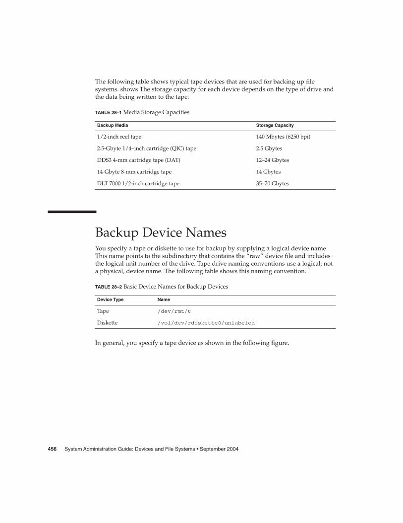
The following table shows typical tape devices that are used for backing up filesystems. shows The storage capacity for each device depends on the type of drive andthe data being written to the tape.
TABLE 28–1 Media Storage Capacities
Backup Media Storage Capacity
1/2-inch reel tape 140 Mbytes (6250 bpi)
2.5-Gbyte 1/4–inch cartridge (QIC) tape 2.5 Gbytes
DDS3 4-mm cartridge tape (DAT) 12–24 Gbytes
14-Gbyte 8-mm cartridge tape 14 Gbytes
DLT 7000 1/2-inch cartridge tape 35–70 Gbytes
Backup Device NamesYou specify a tape or diskette to use for backup by supplying a logical device name.This name points to the subdirectory that contains the “raw” device file and includesthe logical unit number of the drive. Tape drive naming conventions use a logical, nota physical, device name. The following table shows this naming convention.
TABLE 28–2 Basic Device Names for Backup Devices
Device Type Name
Tape /dev/rmt/n
Diskette /vol/dev/rdiskette0/unlabeled
In general, you specify a tape device as shown in the following figure.
456 System Administration Guide: Devices and File Systems • September 2004

Devices directory
Drive number (0-n)
Berkeley compatability
Optional no-rewind n no-rewind omit for re-wind
Raw magnetic tape device directory
/dev/rmt/XAbn
Optional densityl lowm mediumh highu ultrac compressed
FIGURE 28–1 Tape Drive Device Names
If you don’t specify the density, a tape drive typically writes at its “preferred” density.The preferred density usually means the highest density the tape drive supports. MostSCSI drives can automatically detect the density or format on the tape and read itaccordingly. To determine the different densities that are supported for a drive, look atthe /dev/rmt subdirectory. This subdirectory includes the set of tape device files thatsupport different output densities for each tape.
Also, a SCSI controller can have a maximum of seven SCSI tape drives.
Specifying the Rewind Option for a Tape DriveNormally, you specify a tape drive by its logical unit number, which can run from 0 ton. The following table describes how to specify tape device names with a rewind or ano rewind option.
TABLE 28–3 Specifying Rewind or No-Rewind for a Tape Drive
Drive and Rewind Value Use This Option
First drive, rewind /dev/rmt/0
First drive, no rewind /dev/rmt/0n
Second drive, rewind /dev/rmt/1
Second drive, no rewind /dev/rmt/1n
Chapter 28 • Managing Tape Drives (Tasks) 457

Specifying Different Densities for a Tape DriveBy default, the drive writes at its “preferred” density, which is usually the highestdensity the tape drive supports. If you do not specify a tape device, the commandwrites to drive number 0 at the default density the device supports.
To transport a tape to a system whose tape drive supports only a certain density,specify a device name that writes at the desired density. The following table describeshow to specify different densities for a tape drive.
TABLE 28–4 Specifying Different Densities for a Tape Drive
Drive, Density, and Rewind Value Use This Option
First drive, low density, rewind /dev/rmt/0l
First drive, low density, no rewind /dev/rmt/0ln
Second drive, medium density, rewind /dev/rmt/1m
Second drive, medium density, no rewind /dev/rmt/1mn
The additional density values are shown in “Backup Device Names” on page 456.
Displaying Tape Drive StatusYou can use the status option with the mt command to get status information abouttape drives. The mt command reports information about any tape drives that aredescribed in the /kernel/drv/st.conf file.
� How to Display Tape Drive Status
1. Load a tape into the drive you want information about.
2. Display the tape drive status.
# mt -f /dev/rmt/n status
3. Repeat steps 1-2, substituting tape drive numbers 0, 1, 2, 3, and so on to displayinformation about all available tape drives.
Displaying Tape Drive Status
The following example shows the status for a QIC-150 tape drive (/dev/rmt/0):
Steps
Example 28–1
458 System Administration Guide: Devices and File Systems • September 2004

$ mt -f /dev/rmt/0 statusArchive QIC-150 tape drive:
sense key(0x0)= No Additional Sense residual= 0 retries= 0
file no= 0 block no= 0
The following example shows the status for an Exabyte tape drive (/dev/rmt/1):
$ mt -f /dev/rmt/1 statusExabyte EXB-8200 8mm tape drive:sense key(0x0)= NO Additional Sense residual= 0 retries= 0
file no= 0 block no= 0
The following example shows a quick way to poll a system and locate all of its tapedrives:
$ for drive in 0 1 2 3 4 5 6 7> do> mt -f /dev/rmt/$drive status> doneArchive QIC-150 tape drive:
sense key(0x0)= No Additional Sense residual= 0 retries= 0file no= 0 block no= 0
/dev/rmt/1: No such file or directory/dev/rmt/2: No such file or directory/dev/rmt/3: No such file or directory/dev/rmt/4: No such file or directory/dev/rmt/5: No such file or directory/dev/rmt/6: No such file or directory/dev/rmt/7: No such file or directory
$
Handling Magnetic Tape CartridgesIf errors occur when a tape is being read, you can retension the tape, clean the tapedrive, and then try again.
How to Retension a Magnetic Tape CartridgeRetension a magnetic tape cartridge with the mt command.
For example:
$ mt -f /dev/rmt/1 retension
$
Chapter 28 • Managing Tape Drives (Tasks) 459

Note – Do not retension non-QIC tape drives.
How to Rewind a Magnetic Tape CartridgeTo rewind a magnetic tape cartridge, use the mt command.
For example:
$ mt -f /dev/rmt/1 rewind
$
Guidelines for Drive Maintenance andMedia HandlingA backup tape that cannot be read is useless. So, periodically clean and check yourtape drives to ensure correct operation. See your hardware manuals for instructions onprocedures for cleaning a tape drive. You can check your tape hardware by doingeither of the following:
� Copying some files to the tape, reading the files back, and then comparing theoriginal files with the copied files.
� Using the -v option of the ufsdump command to verify the contents of the mediawith the source file system. The file system must be unmounted or completely idlefor the -v option to be effective.
Be aware that hardware can fail in ways that the system does not report.
Always label your tapes after a backup. If you are using a backup strategy similar tothe strategies suggested in Chapter 22, you should indicate on the label “Tape A,”“Tape B,” and so forth. This label should never change. Every time you do a backup,make another tape label that contains the following information:
� The backup date� The name of the machine and file system backed up� The backup level� The tape number (1 of n, if the backup spans multiple volumes)� Any information specific to your site
Store your tapes in a dust-free safe location, away from magnetic equipment. Somesites store archived tapes in fireproof cabinets at remote locations.
You should create and maintain a log that tracks which media (tape volume) storeseach job (backup) and the location of each backed-up file.
460 System Administration Guide: Devices and File Systems • September 2004

Index
Numbers and Symbols4.3 Tahoe file system, 2509660 CD format, 30
Aaccessing
disk devices, 153, 156pathnames for removable media, 25removable media (how to), 32tape devices, 156
addinga disk (overview)
SPARC, 202x86, 212-223
entry to /etc/vfstab file (how to), 281PCI adapter card (how to), 96swap to vfstab, 325
allocated inodes, 336archiving, files to multiple diskettes with cpio
command (how to), 454autoconfiguration process, 69autofs, 264-265automounting, and /home, 265
Bbacking up
and restoring file systemscommands for, 370definition, 370
backing up (Continued)choosing file systems to, 371full and incremental, defined, 373preparing for (overview), 388-389reasons for, 371types of, 373
backupdevice names, 456-458record of incremental, 423
backup schedulesdaily cumulative, weekly cumulative
backups, 379daily cumulative, weekly incremental
backups, 380daily incremental, weekly cumulative
backups, 381-382examples, 379, 385for a server, 382-385guidelines for, 375recommendations, 376using dump levels for, 378
bad block numbers, 337bad inode number, 339bad superblock, 346block disk device interface
defined, 153when to use, 154
blocksbad, 337boot, 358data, 360directory data, 338duplicate, 337
461

blocks (Continued)free, 360indirect, 338logical size, 361regular data, 339special inodes, 336
boot block, 358BSD Fat Fast File system, 250bus-oriented disk controllers, 155bytes (number per inode), 363-364
CCacheFS file systems
checking with fsck command (exampleof), 304
collecting CacheFS statistics (overview), 314creating (how to), 295creating a packing list (how to), 308deleting (how to), 303displaying information about (how to), 301displaying packed files (example of), 307displaying packed files (how to), 307locating CacheFS log file, 316mounting (how to), 296overview, 293packing files in the cache (how to), 309packing with cachefspack command (how
to), 306packing with cachefspack command
(overview), 305parameters, 293setting up CacheFS logging (how to), 316stopping CacheFS logging, 317troubleshooting cachefspack errors, 310unpacking files (how to), 309viewing CacheFS statistics, 318
cachefspack commandhow to use, 306overview, 305
causes of file system damage, 332cdrw command
description, 55identifying CD media (how to), 58restricting access to (how to), 58writing data and audio CDs (overview), 57
CDsISO 9660 format, 30names, 28UFS CDs
SPARC vs. x86 format, 30cfgadm
PCI hot-plugging (overview), 79SCSI hot-plugging (overview), 79
cfsadmin command, 295, 303changing, primary USB audio device (how
to), 142character special inodes, 336checking
and repairing file systems, 340CacheFS file systems (example of), 304file system size, 335format and type of inodes, 336free blocks, 335free inodes, 335inode list for consistency, 335
clri command, 255collecting, CacheFS statistics (overview), 314configuring, a USB device(how to), 146connecting, a USB device(how to), 147copying
complete file systems (dd), 435directories between file systems with cpio
command (overview), 438files to diskette (overview), 451groups of files with cpio command
(overview), 438individual files with cpio command
(overview), 438cpio command
copying directories between file systems(how to), 438
extract all files from tape (how to), 447listing files on tape (how to), 446overview, 438-439
creatinga data CD file system (how to), 60a full backup of UFS snapshot information
(how to), 403a packing list (how to), 308a UFS snapshot
example of, 400a UFS snapshot (how to), 400file systems (overview), 268
462 System Administration Guide: Devices and File Systems • September 2004

creating (Continued)loopback file system (overview), 271swap file, 327
custom parameters for file systems, 361-364cylinder group, 357-360
Ddaily discrete backups, 378damage to file systems, 332data block, 339, 360data directory blocks, 338dd command
cloning disks (how to), 436overview, 435
defaultfile system for /tmp (TMPFS), 253SunOS file system, 256-257
deletingCacheFS file systems (how to), 303UFS snapshot information
example of, 402detecting end of media
cpio command, 438ufsdump command, 422
determiningfile system types, 265mounted file systems, 280tape device name, 409type of tape drive, 409
/dev/dsk directory, 153/dev/rdsk directory, 153devfsadm command, 152device driver
adding, 77defined, 69
device instance name, 152device names
backup, 456-458finding a file system name, 409finding tape, 409
devices, accessing, 151df command, 154, 255dfstab file, configuring for shared local
removable media (how to), 37direct I/O, 260
directoriescopying between file systems with cpio
command (overview), 438inodes, 336/proc, 253/tmp, 253unallocated blocks, 338
disconnectinga SCSI controller (how to), 87a USB device subtree (how to), 147
diskadding to a (overview)
x86, 212-223automatic configuration of SCSI drives, 194formatting a (overview), 173repairing defective sectors, 197, 199when to format (overview), 182
disk-based file systems, 250-251disk controllers, 154disk label
creating (overview), 187description, 174
disk slicesdefined, 165determining which slices to use, 170displaying information about
(overview), 185-187requirements for system configurations, 170
diskettesarchiving files to multiple with cpio
command (how to), 454loading
with volume management, 48loading with volume management (how
to), 46disks
adding to a (overview)SPARC, 202
connecting a secondary disk (example of)SPARC, 207
creating disk slices and labeling a disk(example of)SPARC, 206
creating disk slices and labeling a disk (howto)SPARC, 204
determining if formatted (how to), 183
463
disks (Continued)recovering a corrupted disk label (howto), 191recovering a corrupted disk label
(overview), 190displaying
device information, 74disk slice information (overview), 185packed files (example of), 307packed files (how to), 307removable media user (how to), 34swap space, 326-327system configuration information, 71, 73USB device information (how to), 128
dmesg command, 74SPARC example, 74x86 example, 74
DOS, file system, 250driver not attached message, 71dump levels
daily, incremental backups, 378defined, 378
duplicate blocks, 337DVD-ROM, 252dynamic reconfiguration, 79
Eeject command, removable media (how
to), 35ejecting, removable media (how to), 35end-of-media detection
cpio command, 438ufsdump command, 422
/etc/dfs/dfstab file, configuring for sharedremovable media (how to), 37
/etc/dumpdates file, 422-423/etc/rmmount.conf file, sharing removable
media drives (how to), 37/export/home directory, 257extended fundamental types (UFS file
system), 258
FFDFS file system, 254
ff command, 255FIFO inodes, 336FIFOFS file system, 254file system name, 409file system table, virtual, 263file systems
/, 2574.3 Tahoe, 250BSD Fat Fast, 250cached (overview), 293checking and repairing, 340checking size, 335copying complete (dd), 435creating (overview)
loopback (LOFS), 271custom parameters, 361-364cylinder group struct, 357-360damage to, 332default SunOS, 256-257description of administration
commands, 255disk-based, 250-251DOS, 250/export/home, 257FDFS, 254FIFOFS, 254finding types, 265fixing, 345High Sierra, 250ISO 9660, 250large, 277making available (overview), 275-280manual pages for, 256MNTFS, 257mount table, 262NAMEFS, 254network-based, 251/opt, 257PCFS, 250preening, 344, 345/proc, 257process, overview, 253PROCFS, overview, 253pseudo, overview, 251-254reasons for inconsistencies, 334sharing, 264SPECFS, 254
464 System Administration Guide: Devices and File Systems • September 2004
file systems (Continued)stopping all processes accessing (howto), 288SWAPFS, 254TMPFS, 252-253types of, 250-254UFS, 250UNIX, 250/usr, 257/var, 257which to back up, 371why you back up, 371
filesarchiving to multiple diskettes with cpio
command (how to), 454commands for copying to media
(overview), 433/etc/default/fs, 265/etc/dfs/fstypes, 265in the /proc directory, 253retrieving from tape with tar command
(how to), 442sharing, 264
findingfile system name, 409tape device name, 409type of file system, 265
fixing inconsistent file systems, 345format.dat file
creating an entry (how to), 194creating an entry (overview), 194keywords, 233, 236syntax rules, 233
format of inodes, 336format utility
analyze menu, 229-231automatic configuration of SCSI disk drives
(how to), 196automatic configuration of SCSI disk drives
(overview), 194creating a Solaris fdisk partition (how
to), 215creating disk slices and labeling disk (how
to)SPARC, 204x86, 220
defect menu, 231-232
format utility (Continued)determining if a disk is formatted (howto), 182displaying disk slice information (example
of), 186fdisk menu, 228-229features and benefits, 170formatting a disk (example of), 184guidelines for using, 172-173how to enter command names, 238how to specify block numbers, 237identifying disks on a system (examples
of), 182identifying disks on a system (how to), 180input to, 237, 238labeling a disk
example of, 188main menu, 226overview, 170partition menu, 228recommendations for preserving
information, 225recovering corrupted disk label (how
to), 191using help facility, 239when to use, 171
formatting a disk, overview, 173fragment size, 362free blocks, 335, 360free hog slice, See donor slicefree inodes, 335free space (minimum), 362-363fsck command, 154, 255
checkingfree blocks, 335free inodes, 335inode list size, 335superblock, 334
conditions to repair, 333FSACTIVE state flag, 332FSBAD state flag, 332FSCLEAN state flag, 332FSSTABLE state flag, 332preening, 344state flags, 332syntax and options, 348using interactively, 340
fsdb command, 255
465

fssnap command, creating a UFS snapshot(how to), 400
fstyp command, 255fstypes file, 265full backup
definition, 373example of, 391, 393
fuser commandfinding if removable media is in use (how
to), 34killing processes accessing removable media
(how to), 34
Ggrep command, 265
HHigh Sierra file system, 250/home (automounted), 265hot-plugging
adding PCI adapter card (how to), 96disconnecting a SCSI controller with cfgadm
command (how to), 87overview, 79PCI devices (overview), 94removing PCI adapter card (how to), 95
HSFS, See High Sierra file system
II/O, direct, 260identifying
CD media (how to), 58devices, 72disks on a system (how to), 180
inconsistencies in file systems, 334incorrect . and .. entries, 339incremental backup, 373, 423
example of, 392indirect blocks, 338inode list size, 335inode states, 336inodes, 358-360
inodes (Continued)bad number, 339block special, 336character special, 336checking format and type, 336directory, 336FIFO, 336link count, 336number of bytes per, 363-364regular, 336size, 337symbolic link, 336
installboot command, 209, 222installing a boot block (how to), SPARC, 209ISO 9660 file system, 250ISO standards, 9660 CD format, 30
K/kernel/drv directory, 70killing
all processes accessing a file system (howto), 288
processes accessing removable media (howto), 34
Llabelit command, 255large files option, 277level 0 backup, 378link count of inodes, 336loading
disketteswith volume management, 48
diskettes with volume management (howto), 46
locating, CacheFS log file, 316log (record of dumps), 422-423logical block size, 361logical device name
definition, 152disk, 153tape, 156
logical device names, removable media, 157
466 System Administration Guide: Devices and File Systems • September 2004

loopback file system (LOFS)creating (overview), 271mounting, 282
lost+found directory, 332
Mmaintaining tape drives, 460manual pages, for file systems, 256media was found message, 47memory storage (virtual), definition, 322minimum free space, 362-363mkfile command, 327, 328mkfs command, 255, 268mkisofs command, create a data CD file
system (how to), 60MNTFS file system, 257mnttab file, 262mount command, 154mount point, definition, 261mount table, 262mountall command, 255mounting
a file system with /etc/vfstab, 282all files in vfstab file, 282file systems automatically, 264-265loopback file systems (LOFS), 282NFS file systems, 281PCMCIA memory cards on other systems
(example of), 41remote removable media manually (example
of), 40removable media
automatic mounting compared to, 24UFS file systems, 281UFS file systems (how to)
without large files, 284USB mass storage devices with vold running
(how to), 132mt command, 459
NNAMEFS file system, 254ncheck command, 255network-based file systems, 251
newfs command, 154, 268, 364-368NFS
description, 264server description, 264vfstab entry for, 281
nfsd daemonstarting, 37verifying if running, 36
no media was found message, 47
O/opt directory, 257optimization type, 363options, for ufsdump command, 426
Pparameters (file system), 361-364partition (swap), definition, 322passwd file, restoring from tape (example
of), 414PCFS file system, 250PCI devices
adding PCI adapter card (how to), 96removing PCI adapter card (how to), 95troubleshooting PCI configuration
problems, 97PCMCIA memory cards
accessing on other systems (example of), 41mounting remotely (example of), 41
physical device name, definition, 152preening file systems, 344, 345preparing
for backing up (overview), 388-389to restore files (overview), 408-409
/proc directory, 253, 257process file system (PROCFS), 253PROCFS file system, overview, 253prtconf command, 72prtvtoc command, 154
example of using, 189pseudo file systems, overview, 251-254
467

Rraw disk device interface, 153, 154reconfiguration boot, 195
SPARC example, 203x86 example, 213
record ofdumps, 422-423incremental backup, 423
regular inodes, 336removable media
accessing (examples of), 32accessing (how to), 32accessing media on other systems (example
of), 40ejecting (how to), 35finding out if media is in use (how to), 34killing processes accessing (how to), 34mounting
manual compared to automatic, 24mounting remote media (example of), 40names, 28
removinga swap file from use, 329PCI adapter card (how to), 95
resetting, a USB device (how to), 148resolving, a failed SCSI unconfigure operation
(how to), 93restoring bad superblock, 346restoring file systems
complete (example), 417complete (example of), 415determining which tapes to use (how
to), 410preparing to (overview), 408-409root and /usr (SPARC) (example of), 420root and /usr (x86) (example of), 420type of tape drive, 409
restoring filesexample of interactive restore, 412example of non-interactive restore, 414
restricting, removable media access (howto), 58
retrieving, files from tape withtar command(how to), 442
rmmount.conf file, sharing removable mediadrives (how to), 37
Rock Ridge extension (HSFS file system), 250root (/) file system, 257
Sscheduling backups, 375SCSI devices
disconnecting with cfgadm command (howto), 87
resolving a failed SCSI unconfigure operation(how to), 93
troubleshooting SCSI configurationproblem, 91
SCSI disk drives, 194SCSI tape drives, 457secondary disk
connecting to the system (how to)SPARC, 204x86, 214
description, 169setting up, CacheFS logging, 316share command, 264
making removable media available to othersystems (how to), 37
shareall command, 264sharing, files, 264size
checking file system, 335fragment, 362inode, 337
slice (defined), 165Solaris fdisk partition, guidelines, 214-215space optimization type, 363SPARC based systems, UFS format, 30SPECFS file system, 254specifying a disk slice, 154, 156starting
nfsd daemon, 37volume management (how to), 31
state flagfsck, 332UFS file systems, 258
stoppingall processes for a file system (how to), 288CacheFS logging, 317killing processes accessing removable media
(how to), 34volume management (how to), 31
storage (virtual memory), definition, 322storage capacities (media), 374, 456structure of cylinder groups, 357-360SunOS default file system, 256-257
468 System Administration Guide: Devices and File Systems • September 2004

superblock, 334, 346, 358swap command, 327swap file
adding to vfstab, 325creating, 327displaying, 326-327removing from use, 329
swap partition, definition, 322swapadd command, 325SWAPFS file system, 254symbolic links, 336syntax
fsck command, 348newfs, 364-368
sysdef command, 72system disk
connecting (how to)x86, 213
description, 169
Ttape
capacity, 425characteristics, 425retrieving files from with tar command
(how to), 442sizes, 374, 456storage capacities, 374, 456
tape devices (naming), 156tape drive
determining type for restore, 409maintaining, 460maximum SCSI, 457rewind, 457-458
tar commandcopying files to remote tape with dd
command (how to), 449listing files on diskette (how to), 453listing files on tape (how to), 442overview, 441retrieving files from diskette (how to), 453retrieving files from remote tape with dd
command (how to), 450retrieving files from tape (how to), 442
temporary file system (TMPFS),overview, 252-253
time (optimization type), 363/tmp directory, 253, 257TMPFS file system, overview, 252-253troubleshooting
cachefspack errors, 310PCI configuration problems, 97SCSI configuration problems, 91USB audio device problems, 142
type of file systems, 250-254type of inodes, 336
UUDF file system, 252UFS CDs, SPARC vs. x86 formats, 30UFS file system, 250, 258-260
extended fundamental types, 258large file systems, 258mounting, 281mounting with /etc/vfstab, 282mounting without large files (how to), 284state flags, 258
UFS logging, overview, 259UFS snapshot
creating (how to), 400creating a full backup of (howto), 403description, 398
ufsdump commandend-of-media detection, 422full backup example, 391, 393how data is copied with, 422how it works, 421-426incremental backup example, 392limitations, 425options and arguments, 426
ufsdump command (overview), 390ufsrestore command, 429
determining which tapes to use (howto), 410
preparing to use (overview), 408umount command, 255umountall command, 255unallocated directory blocks, 338unallocated inodes, 336UNIX file system, 250unmounting, USB mass storage devices with
vold running (how to), 132
469

unsupported devices, 70USB devices
acronyms, 115audio
changing the primary device (howto), 142
device ownership, 142overview of, 139
bus description, 115cables for, 121composite device, 116compound device, 116configuring a USB device (how to), 146connect a USB device (how to), 147connect a USB device subtree (how to), 147device classes, 117device nodes, 117displaying device information (how to), 128drivers, 117host controller and root hub, 119hot-plugging (overview), 135keyboards and mouse devices, 118mounting mass storage with vold running
(how to), 131names of, 116overview, 114physical device hierarchy, 116power management, 120resetting a USB device (how to), 148Solaris USB Architecture (USBA), 117storage devices, 125supported, 110troubleshooting audio device problems, 142unmounting mass storage with vold running
(how to), 131/usr file system, 257
V/var directory, 257verifying, nfsd daemon is running, 36vfstab file, 265, 325
adding entries to (how to), 281adding swap to, 325default, 263entry for LOFS, 273mounting all files, 282
viewing, CacheFS statistics, 318virtual file system table, 263virtual memory storage, definition, 322volcopy command, 255volmgt start command, 31volume management
benefits, 24diskettes
loading, 48loading diskettes (how to), 46manual compared to automatic
mounting, 24removable media
accessing, 25restarting (how to), 31stopping (how to), 31
Wwriting, data and audio CDs (overview), 57
Xx86 based systems, UFS format, 30
470 System Administration Guide: Devices and File Systems • September 2004


![Food and Drug Administration - FDAnews · Food and Drug Administration 21 CFR Part 814 [Docket No. FDA-2009-N-0458] RIN 0910-AG29 Medical Devices; Pediatric Uses of Devices; Requirement](https://static.fdocuments.net/doc/165x107/5e7ff6af728c5474fa08ffe3/food-and-drug-administration-fdanews-food-and-drug-administration-21-cfr-part.jpg)


