SYSMAC CS/CJ Series CS Series: CS1W-DRM21(-V1) CJ Series: CJ1W-DRM21 DeviceNet Units ·...
289
OPERATION MANUAL Cat. No. W380-E1-05 SYSMAC CS/CJ Series CS Series: CS1W-DRM21(-V1) CJ Series: CJ1W-DRM21 DeviceNet Units
Transcript of SYSMAC CS/CJ Series CS Series: CS1W-DRM21(-V1) CJ Series: CJ1W-DRM21 DeviceNet Units ·...
OPERATION MANUAL
Cat. No. W380-E1-05
SYSMAC CS/CJ SeriesCS Series: CS1W-DRM21(-V1)CJ Series: CJ1W-DRM21DeviceNet Units

CS-series DeviceNet Unit: CS1W-DRM21(-V1)CJ-series DeviceNet Unit: CJ1W-DRM21Operation ManualRevised July 2005

iv

Notice:OMRON products are manufactured for use according to proper procedures by a qualified operatorand only for the purposes described in this manual.
The following conventions are used to indicate and classify precautions in this manual. Always heedthe information provided with them. Failure to heed precautions can result in injury to people or dam-age to property.
!DANGER Indicates an imminently hazardous situation which, if not avoided, will result in death orserious injury. Additionally, there may be severe property damage.
!WARNING Indicates a potentially hazardous situation which, if not avoided, could result in death orserious injury. Additionally, there may be severe property damage.
!Caution Indicates a potentially hazardous situation which, if not avoided, may result in minor ormoderate injury, or property damage.
OMRON Product ReferencesAll OMRON products are capitalized in this manual. The word “Unit” is also capitalized when it refers toan OMRON product, regardless of whether or not it appears in the proper name of the product.
The abbreviation “Ch,” which appears in some displays and on some OMRON products, often means“word” and is abbreviated “Wd” in documentation in this sense.
The abbreviation “PLC” means Programmable Controller. “PC” is used, however, in some Program-ming Device displays to mean Programmable Controller.
Visual AidsThe following headings appear in the left column of the manual to help you locate different types ofinformation.
Note Indicates information of particular interest for efficient and convenient opera-tion of the product.
Reference Indicates supplementary information on related topics that may be of interestto the user.
1,2,3... 1. Indicates lists of one sort or another, such as procedures, checklists, etc.
v
Trademarks and CopyrightsDeviceNet is a registered trademark of the Open DeviceNet Vendor Association, Inc.
Windows, Windows 95, Windows 98, Windows Me, Windows NT, and Windows 2000 are registeredtrademarks of the Microsoft Corporation.
Other product names and company names in this manual are trademarks or registered trademarks oftheir respective companies.
The copyright of the DeviceNet Unit belongs to OMRON Corporation.
OMRON, 2000All rights reserved. No part of this publication may be reproduced, stored in a retrieval system, or transmitted, in any form, orby any means, mechanical, electronic, photocopying, recording, or otherwise, without the prior written permission ofOMRON.
No patent liability is assumed with respect to the use of the information contained herein. Moreover, because OMRON is con-stantly striving to improve its high-quality products, the information contained in this manual is subject to change withoutnotice. Every precaution has been taken in the preparation of this manual. Nevertheless, OMRON assumes no responsibilityfor errors or omissions. Neither is any liability assumed for damages resulting from the use of the information contained inthis publication.
vi

TABLE OF CONTENTS
PRECAUTIONS . . . . . . . . . . . . . . . . . . . . . . . . . . . . . . . . xv1 Intended Audience . . . . . . . . . . . . . . . . . . . . . . . . . . . . . . . . . . . . . . . . . . . . . . . . . xvi
2 General Precautions . . . . . . . . . . . . . . . . . . . . . . . . . . . . . . . . . . . . . . . . . . . . . . . . xvi
3 Safety Precautions. . . . . . . . . . . . . . . . . . . . . . . . . . . . . . . . . . . . . . . . . . . . . . . . . . xvi
4 Operating Environment Precautions . . . . . . . . . . . . . . . . . . . . . . . . . . . . . . . . . . . . xvii
5 Application Precautions . . . . . . . . . . . . . . . . . . . . . . . . . . . . . . . . . . . . . . . . . . . . . xviii
6 Conformance to EC Directives . . . . . . . . . . . . . . . . . . . . . . . . . . . . . . . . . . . . . . . . xx
SECTION 1Features and System Configuration . . . . . . . . . . . . . . . . 1
1-1 Overview of DeviceNet. . . . . . . . . . . . . . . . . . . . . . . . . . . . . . . . . . . . . . . . . . . . . . 2
1-2 DeviceNet Unit Features . . . . . . . . . . . . . . . . . . . . . . . . . . . . . . . . . . . . . . . . . . . . . 16
1-3 Specifications . . . . . . . . . . . . . . . . . . . . . . . . . . . . . . . . . . . . . . . . . . . . . . . . . . . . . 22
1-4 Comparison with Previous Models . . . . . . . . . . . . . . . . . . . . . . . . . . . . . . . . . . . . . 30
1-5 Outline of the Configurator . . . . . . . . . . . . . . . . . . . . . . . . . . . . . . . . . . . . . . . . . . . 34
1-6 Basic Operating Procedures . . . . . . . . . . . . . . . . . . . . . . . . . . . . . . . . . . . . . . . . . . 37
1-7 List of Usage Methods by Purpose . . . . . . . . . . . . . . . . . . . . . . . . . . . . . . . . . . . . . 43
SECTION 2Nomenclature and Installation . . . . . . . . . . . . . . . . . . . . 45
2-1 Nomenclature and Functions . . . . . . . . . . . . . . . . . . . . . . . . . . . . . . . . . . . . . . . . . 46
2-2 Installing the DeviceNet Unit . . . . . . . . . . . . . . . . . . . . . . . . . . . . . . . . . . . . . . . . . 51
SECTION 3Allocated CIO and DM Words . . . . . . . . . . . . . . . . . . . . 57
3-1 Overview of Word Allocations . . . . . . . . . . . . . . . . . . . . . . . . . . . . . . . . . . . . . . . . 58
3-2 Allocated CIO Area Words . . . . . . . . . . . . . . . . . . . . . . . . . . . . . . . . . . . . . . . . . . . 60
3-3 Allocated DM Area Words . . . . . . . . . . . . . . . . . . . . . . . . . . . . . . . . . . . . . . . . . . . 81
SECTION 4Remote I/O Master Communications . . . . . . . . . . . . . . . 91
4-1 Master Remote I/O Communications . . . . . . . . . . . . . . . . . . . . . . . . . . . . . . . . . . . 92
4-2 Scan List . . . . . . . . . . . . . . . . . . . . . . . . . . . . . . . . . . . . . . . . . . . . . . . . . . . . . . . . . 99
4-3 Fixed Allocations . . . . . . . . . . . . . . . . . . . . . . . . . . . . . . . . . . . . . . . . . . . . . . . . . . 101
4-4 User-set Allocations . . . . . . . . . . . . . . . . . . . . . . . . . . . . . . . . . . . . . . . . . . . . . . . . 107
4-5 Starting and Stopping Remote I/O Communications . . . . . . . . . . . . . . . . . . . . . . . 116
4-6 Example of Ladder Programming for Remote I/O Communications . . . . . . . . . . . 116
4-7 Errors that May Occur in Remote I/O Communications . . . . . . . . . . . . . . . . . . . . 118
vii
TABLE OF CONTENTS
SECTION 5Remote I/O Slave Communications. . . . . . . . . . . . . . . . . 1215-1 Slave Remote I/O Communications . . . . . . . . . . . . . . . . . . . . . . . . . . . . . . . . . . . 122
5-2 Fixed Allocations. . . . . . . . . . . . . . . . . . . . . . . . . . . . . . . . . . . . . . . . . . . . . . . . . . 125
5-3 User-set Allocations. . . . . . . . . . . . . . . . . . . . . . . . . . . . . . . . . . . . . . . . . . . . . . . . 126
SECTION 6Message Communications . . . . . . . . . . . . . . . . . . . . . . . . 133
6-1 Overview . . . . . . . . . . . . . . . . . . . . . . . . . . . . . . . . . . . . . . . . . . . . . . . . . . . . . . . . 134
6-2 FINS Commands and Responses. . . . . . . . . . . . . . . . . . . . . . . . . . . . . . . . . . . . . . 141
6-3 Using FINS Message Communications. . . . . . . . . . . . . . . . . . . . . . . . . . . . . . . . . 145
6-4 Sending Explicit Messages . . . . . . . . . . . . . . . . . . . . . . . . . . . . . . . . . . . . . . . . . . 157
6-5 Receiving Explicit Messages . . . . . . . . . . . . . . . . . . . . . . . . . . . . . . . . . . . . . . . . . 164
SECTION 7Other Functions. . . . . . . . . . . . . . . . . . . . . . . . . . . . . . . . . 177
7-1 Connecting to the CX-Programmer via the DeviceNet . . . . . . . . . . . . . . . . . . . . . 178
7-2 Memory Card Backup Functions. . . . . . . . . . . . . . . . . . . . . . . . . . . . . . . . . . . . . . 182
7-3 Simple Backup Function . . . . . . . . . . . . . . . . . . . . . . . . . . . . . . . . . . . . . . . . . . . . 185
SECTION 8Communications Timing . . . . . . . . . . . . . . . . . . . . . . . . . 189
8-1 Remote I/O Communications Characteristics . . . . . . . . . . . . . . . . . . . . . . . . . . . . 190
8-2 Message Communications . . . . . . . . . . . . . . . . . . . . . . . . . . . . . . . . . . . . . . . . . . . 196
SECTION 9Troubleshooting and Maintenance . . . . . . . . . . . . . . . . . 201
9-1 Troubleshooting with the DeviceNet Unit Indicators . . . . . . . . . . . . . . . . . . . . . . 202
9-2 Error Log Functions. . . . . . . . . . . . . . . . . . . . . . . . . . . . . . . . . . . . . . . . . . . . . . . . 220
9-3 Troubleshooting . . . . . . . . . . . . . . . . . . . . . . . . . . . . . . . . . . . . . . . . . . . . . . . . . . . 224
9-4 Maintenance and Replacement . . . . . . . . . . . . . . . . . . . . . . . . . . . . . . . . . . . . . . . 227
AppendicesA Allocation Differences from C200H DeviceNet Master Units . . . . . . . . . . . . . . . 231
B DeviceNet Connections . . . . . . . . . . . . . . . . . . . . . . . . . . . . . . . . . . . . . . . . . . . . 237
C FINS Commands and Responses for DeviceNet Units . . . . . . . . . . . . . . . . . . . . 243
D Multi-vendor Applications . . . . . . . . . . . . . . . . . . . . . . . . . . . . . . . . . . . . . . . . . . 249
E DeviceNet Explicit Message Send Command for Other Manufacturer Nodes . . 259
Index . . . . . . . . . . . . . . . . . . . . . . . . . . . . . . . . . . . . . . . . . . 261
Revision History . . . . . . . . . . . . . . . . . . . . . . . . . . . . . . . . 265
viii
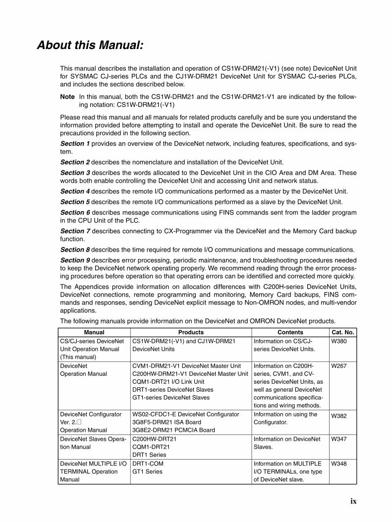
About this Manual:
This manual describes the installation and operation of CS1W-DRM21(-V1) (see note) DeviceNet Unitfor SYSMAC CJ-series PLCs and the CJ1W-DRM21 DeviceNet Unit for SYSMAC CJ-series PLCs,and includes the sections described below.
Note In this manual, both the CS1W-DRM21 and the CS1W-DRM21-V1 are indicated by the follow-ing notation: CS1W-DRM21(-V1)
Please read this manual and all manuals for related products carefully and be sure you understand theinformation provided before attempting to install and operate the DeviceNet Unit. Be sure to read theprecautions provided in the following section.
Section 1 provides an overview of the DeviceNet network, including features, specifications, and sys-tem.
Section 2 describes the nomenclature and installation of the DeviceNet Unit.
Section 3 describes the words allocated to the DeviceNet Unit in the CIO Area and DM Area. Thesewords both enable controlling the DeviceNet Unit and accessing Unit and network status.
Section 4 describes the remote I/O communications performed as a master by the DeviceNet Unit.
Section 5 describes the remote I/O communications performed as a slave by the DeviceNet Unit.
Section 6 describes message communications using FINS commands sent from the ladder programin the CPU Unit of the PLC.
Section 7 describes connecting to CX-Programmer via the DeviceNet and the Memory Card backupfunction.
Section 8 describes the time required for remote I/O communications and message communications.
Section 9 describes error processing, periodic maintenance, and troubleshooting procedures neededto keep the DeviceNet network operating properly. We recommend reading through the error process-ing procedures before operation so that operating errors can be identified and corrected more quickly.
The Appendices provide information on allocation differences with C200H-series DeviceNet Units,DeviceNet connections, remote programming and monitoring, Memory Card backups, FINS com-mands and responses, sending DeviceNet explicit message to Non-OMRON nodes, and multi-vendorapplications.
The following manuals provide information on the DeviceNet and OMRON DeviceNet products.
Manual Products Contents Cat. No.
CS/CJ-series DeviceNet Unit Operation Manual(This manual)
CS1W-DRM21(-V1) and CJ1W-DRM21DeviceNet Units
Information on CS/CJ-series DeviceNet Units.
W380
DeviceNet Operation Manual
CVM1-DRM21-V1 DeviceNet Master UnitC200HW-DRM21-V1 DeviceNet Master UnitCQM1-DRT21 I/O Link UnitDRT1-series DeviceNet SlavesGT1-series DeviceNet Slaves
Information on C200H-series, CVM1, and CV-series DeviceNet Units, as well as general DeviceNet communications specifica-tions and wiring methods.
W267
DeviceNet Configurator Ver. 2.@Operation Manual
WS02-CFDC1-E DeviceNet Configurator3G8F5-DRM21 ISA Board3G8E2-DRM21 PCMCIA Board
Information on using the Configurator.
W382
DeviceNet Slaves Opera-tion Manual
C200HW-DRT21CQM1-DRT21DRT1 Series
Information on DeviceNet Slaves.
W347
DeviceNet MULTIPLE I/O TERMINAL Operation Manual
DRT1-COMGT1 Series
Information on MULTIPLE I/O TERMINALs, one type of DeviceNet slave.
W348
ix

About this Manual, ContinuedManual Products Contents Cat. No.
SYSMAC CS/CJ Series Communication Com-mands Reference Manual
CS1G/H-CPU@@HCS1G/H-CPU@@-EV1CS1D-CPU@@HCS1W-SCU21-V1CS1W-SCB21-V1/41-V1CJ1G/H-CPU@@HCJ1G-CPU@@CJ1M-CPU@@CJ1W-SCU21/41
Information on FINS and Host Link commands that can be sent to CS/CJ-series CPU Units.
W342
CX-Programmer Operation Manual
WS02-CXPC1-EV3 Information on setting and monitoring networks, such as the use of routing tables.
W414
!WARNING Failure to read and understand the information provided in this manual may result in per-sonal injury or death, damage to the product, or product failure. Please read each sectionin its entirety and be sure you understand the information provided in the section andrelated sections before attempting any of the procedures or operations given.
x
Read and Understand this ManualPlease read and understand this manual before using the product. Please consult your OMRON representative if you have any questions or comments.
Warranty and Limitations of Liability
WARRANTY
OMRON's exclusive warranty is that the products are free from defects in materials and workmanship for a period of one year (or other period if specified) from date of sale by OMRON.
OMRON MAKES NO WARRANTY OR REPRESENTATION, EXPRESS OR IMPLIED, REGARDING NON-INFRINGEMENT, MERCHANTABILITY, OR FITNESS FOR PARTICULAR PURPOSE OF THE PRODUCTS. ANY BUYER OR USER ACKNOWLEDGES THAT THE BUYER OR USER ALONE HAS DETERMINED THAT THE PRODUCTS WILL SUITABLY MEET THE REQUIREMENTS OF THEIR INTENDED USE. OMRON DISCLAIMS ALL OTHER WARRANTIES, EXPRESS OR IMPLIED.
LIMITATIONS OF LIABILITY
OMRON SHALL NOT BE RESPONSIBLE FOR SPECIAL, INDIRECT, OR CONSEQUENTIAL DAMAGES, LOSS OF PROFITS OR COMMERCIAL LOSS IN ANY WAY CONNECTED WITH THE PRODUCTS, WHETHER SUCH CLAIM IS BASED ON CONTRACT, WARRANTY, NEGLIGENCE, OR STRICT LIABILITY.
In no event shall the responsibility of OMRON for any act exceed the individual price of the product on which liability is asserted.
IN NO EVENT SHALL OMRON BE RESPONSIBLE FOR WARRANTY, REPAIR, OR OTHER CLAIMS REGARDING THE PRODUCTS UNLESS OMRON'S ANALYSIS CONFIRMS THAT THE PRODUCTS WERE PROPERLY HANDLED, STORED, INSTALLED, AND MAINTAINED AND NOT SUBJECT TO CONTAMINATION, ABUSE, MISUSE, OR INAPPROPRIATE MODIFICATION OR REPAIR.
xi

Application Considerations
SUITABILITY FOR USE
OMRON shall not be responsible for conformity with any standards, codes, or regulations that apply to the combination of products in the customer's application or use of the products.
At the customer's request, OMRON will provide applicable third party certification documents identifying ratings and limitations of use that apply to the products. This information by itself is not sufficient for a complete determination of the suitability of the products in combination with the end product, machine, system, or other application or use.
The following are some examples of applications for which particular attention must be given. This is not intended to be an exhaustive list of all possible uses of the products, nor is it intended to imply that the uses listed may be suitable for the products:
• Outdoor use, uses involving potential chemical contamination or electrical interference, or conditions or uses not described in this manual.
• Nuclear energy control systems, combustion systems, railroad systems, aviation systems, medical equipment, amusement machines, vehicles, safety equipment, and installations subject to separate industry or government regulations.
• Systems, machines, and equipment that could present a risk to life or property.
Please know and observe all prohibitions of use applicable to the products.
NEVER USE THE PRODUCTS FOR AN APPLICATION INVOLVING SERIOUS RISK TO LIFE OR PROPERTY WITHOUT ENSURING THAT THE SYSTEM AS A WHOLE HAS BEEN DESIGNED TO ADDRESS THE RISKS, AND THAT THE OMRON PRODUCTS ARE PROPERLY RATED AND INSTALLED FOR THE INTENDED USE WITHIN THE OVERALL EQUIPMENT OR SYSTEM.
PROGRAMMABLE PRODUCTS
OMRON shall not be responsible for the user's programming of a programmable product, or any consequence thereof.
xii
Disclaimers
CHANGE IN SPECIFICATIONS
Product specifications and accessories may be changed at any time based on improvements and other reasons.
It is our practice to change model numbers when published ratings or features are changed, or when significant construction changes are made. However, some specifications of the products may be changed without any notice. When in doubt, special model numbers may be assigned to fix or establish key specifications for your application on your request. Please consult with your OMRON representative at any time to confirm actual specifications of purchased products.
DIMENSIONS AND WEIGHTS
Dimensions and weights are nominal and are not to be used for manufacturing purposes, even when tolerances are shown.
PERFORMANCE DATA
Performance data given in this manual is provided as a guide for the user in determining suitability and does not constitute a warranty. It may represent the result of OMRON's test conditions, and the users must correlate it to actual application requirements. Actual performance is subject to the OMRON Warranty and Limitations of Liability.
ERRORS AND OMISSIONS
The information in this manual has been carefully checked and is believed to be accurate; however, no responsibility is assumed for clerical, typographical, or proofreading errors, or omissions.
xiii

xiv
xv
PRECAUTIONS
This section provides general precautions for using the DeviceNet Unit and related devices.
The information contained in this section is important for the safe and reliable application of the DeviceNet Unitand Programmable Controller (PLC) You must read this section and understand the information contained beforeattempting to set up or operate a DeviceNet Unit as part of a PLC.
1 Intended Audience . . . . . . . . . . . . . . . . . . . . . . . . . . . . . . . . . . . . . . . . . . . . . xvi2 General Precautions . . . . . . . . . . . . . . . . . . . . . . . . . . . . . . . . . . . . . . . . . . . . xvi3 Safety Precautions. . . . . . . . . . . . . . . . . . . . . . . . . . . . . . . . . . . . . . . . . . . . . . xvi4 Operating Environment Precautions . . . . . . . . . . . . . . . . . . . . . . . . . . . . . . . . xvii5 Application Precautions . . . . . . . . . . . . . . . . . . . . . . . . . . . . . . . . . . . . . . . . . xviii6 Conformance to EC Directives . . . . . . . . . . . . . . . . . . . . . . . . . . . . . . . . . . . . xx
6-1 Applicable Directives . . . . . . . . . . . . . . . . . . . . . . . . . . . . . . . . . . . . xx6-2 Concepts . . . . . . . . . . . . . . . . . . . . . . . . . . . . . . . . . . . . . . . . . . . . . . xx6-3 Conformance to EC Directives . . . . . . . . . . . . . . . . . . . . . . . . . . . . . xx
Intended Audience 1
1 Intended AudienceThis manual is intended for the following personnel, who must also haveknowledge of electrical systems (an electrical engineer or the equivalent).
• Personnel in charge of installing FA systems.
• Personnel in charge of designing FA systems.
• Personnel in charge of managing FA systems and facilities.
2 General PrecautionsThe user must operate the product according to the performance specifica-tions described in the operation manuals.
Before using the product under conditions which are not described in themanual or applying the product to nuclear control systems, railroad systems,aviation systems, vehicles, combustion systems, medical equipment, amuse-ment machines, safety equipment, and other systems, machines, and equip-ment that may have a serious influence on lives and property if usedimproperly, consult your OMRON representative.
Make sure that the ratings and performance characteristics of the product aresufficient for the systems, machines, and equipment, and be sure to providethe systems, machines, and equipment with double safety mechanisms.
This manual provides information for installing and operating the DeviceNetUnit. Be sure to read this manual before operation and keep this manual closeat hand for reference during operation.
!WARNING It is extremely important that a PLC and all PLC Units be used for the speci-fied purpose and under the specified conditions, especially in applications thatcan directly or indirectly affect human life. You must consult with yourOMRON representative before applying a PLC System to the above men-tioned applications.
3 Safety Precautions
!WARNING Never attempt to disassemble a Unit or touch the inside of Unit while power isbeing supplied. Doing so may result in serious electrical shock or electrocu-tion.
!WARNING Provide safety measures in external circuits, i.e., not in the ProgrammableController (CPU Unit including associated Units; referred to as “PLC”), inorder to ensure safety in the system if an abnormality occurs due to malfunc-tion of the PLC or another external factor affecting the PLC operation. Notdoing so may result in serious accidents.
• Emergency stop circuits, interlock circuits, limit circuits, and similar safetymeasures must be provided in external control circuits.
• The PLC will turn OFF all outputs when its self-diagnosis function detectsany error or when a severe failure alarm (FALS) instruction is executed.As a countermeasure for such errors, external safety measures must beprovided to ensure safety in the system.
• The PLC outputs may remain ON or OFF due to deposition or burning ofthe output relays or destruction of the output transistors. As a counter-
xvi
Operating Environment Precautions 4
measure for such problems, external safety measures must be providedto ensure safety in the system.
• When the 24-VDC output (service power supply to the PLC) is overloadedor short-circuited, the voltage may drop and result in the outputs beingturned OFF. As a countermeasure for such problems, external safetymeasures must be provided to ensure safety in the system.
!WARNING The CPU Unit refreshes I/O even when the program is stopped (i.e., even inPROGRAM mode). Confirm safety thoroughly in advance before changing thestatus of any part of memory allocated to I/O Units, Special I/O Units, or CPUBus Units. Any changes to the data allocated to any Unit may result in unex-pected operation of the loads connected to the Unit. Any of the following oper-ation may result in changes to memory status.
• Transferring I/O memory data to the CPU Unit from a ProgrammingDevice.
• Changing present values in memory from a Programming Device.
• Force-setting/-resetting bits from a Programming Device.
• Transferring I/O memory files from a Memory Card or EM file memory tothe CPU Unit.
• Transferring I/O memory from a host computer or from another PLC on anetwork.
!Caution Execute online edit only after confirming that no adverse effects will becaused by extending the cycle time. Otherwise, the input signals may not bereadable.
!Caution Confirm safety at the destination node before transferring a program toanother node or changing contents of the I/O memory area. Doing either ofthese without confirming safety may result in injury.
4 Operating Environment PrecautionsDo not install the Unit in any of the following locations.
• Locations subject to direct sunlight.
• Locations subject to temperatures or humidities outside the range speci-fied in the specifications.
• Locations subject to condensation as the result of severe changes in tem-perature.
• Locations subject to corrosive or flammable gases.
• Locations subject to dust (especially iron dust) or salt.
• Locations subject to exposure to water, oil, or chemicals.
• Locations subject to shock or vibration.
Provide proper shielding when installing in the following locations:
• Locations subject to static electricity or other sources of noise.
• Locations subject to strong electromagnetic fields.
• Locations subject to possible exposure to radiation.
• Locations near to power supply lines.
xvii

Application Precautions 5
!Caution The operating environment of the PLC System can have a large effect on thelongevity and reliability of the system. Improper operating environments canlead to malfunction, failure, and other unforeseeable problems with the PLCSystem. Be sure that the operating environment is within the specified condi-tions at installation and remains within the specified conditions during the lifeof the system.
5 Application PrecautionsObserve the following precautions when using the DeviceNet Unit.
!WARNING Failure to abide by the following precautions could lead to serious or possiblyfatal injury. Always heed these precautions.
• Always connect to a class-3 ground (100 Ω or less) when installing theUnits.
!Caution Failure to abide by the following precautions could lead to faulty operation orthe PLC or the system or could damage the PLC or PLC Units. Always heedthese precautions.
• Install double safety mechanisms to ensure safety against incorrect sig-nals that may be produced by broken signal lines or momentary powerinterruptions.
• Enable the scan list to before operating the system.
• When adding a new node to the network, make sure that the baud rate isthe same as other nodes.
• Use specified communications cables.
• Do not extend connection distances beyond the ranges given in the spec-ifications.
• Always turn OFF the power supply to the personal computer, Slaves, andCommunications Units before attempting any of the following.
• Mounting or dismounting the DeviceNet Unit, Power Supply Units, I/OUnits, CPU Units, or any other Units.
• Assembling a Unit.
• Setting DIP switches or rotary switches.
• Connecting or wiring the cables.
• Connecting or disconnecting connectors.
• Be sure that the terminal blocks, connectors, Memory Units, expansioncables, and other items with locking devices are properly locked intoplace. Improper locking may result in malfunction.
• Be sure that all the mounting screws, terminal screws, Unit mountingscrews, and cable connector screws are tightened to the torque specifiedin the relevant manuals. Incorrect tightening torque may result in malfunc-tion.
• Leave the label attached to the Unit when wiring. Removing the label mayresult in malfunction if foreign matter enters the Unit.
• Remove the label after the completion of wiring to ensure proper heat dis-sipation. Leaving the label attached may result in malfunction.
• Always use the power supply voltage specified in this manual.
xviii

Application Precautions 5
• Double-check all the wiring and connection of terminal blocks and con-nectors before mounting the Units.
• Use crimp terminals for wiring. Do not connect bare stranded wiresdirectly to terminals.
• Observe the following precautions when wiring the communicationscable.
• Separate the communications cables from the power lines or high-ten-sion lines.
• Do not bend the communications cables.
• Do not pull on the communications cables.
• Do not place heavy objects on top of the communications cables.
• Be sure to wire communications cable inside ducts.
• Use appropriate communications cables.
• Take appropriate measures to ensure that the specified power with therated voltage and frequency is supplied in places where the power supplyis unstable. An incorrect power supply may result in malfunction.
• Install external breakers and take other safety measures against short-cir-cuiting in external wiring. Insufficient safety measures against short-cir-cuiting may result in burning.
• Double-check all the wiring and switch settings before turning ON thepower supply.
• Check the user program for proper execution before actually running it onthe Unit. Not checking the program may result in an unexpected opera-tion.
• Confirm that no adverse effect will occur in the system before attemptingany of the following. Not doing so may result in an unexpected operation.
• Changing the operating mode of the PLC.
• Force-setting/force-resetting any bit in memory.
• Changing the present value of any word or any set value in memory.
• After replacing Units, resume operation only after transferring to the newCPU Unit and/or Special I/O Units the contents of the DM Area, HR Area,and other data required for resuming operation. Not doing so may resultin an unexpected operation.
• When transporting or storing the product, cover the PCBs with electricallyconductive materials to prevent LSIs and ICs from being damaged bystatic electricity, and also keep the product within the specified storagetemperature range.
• When transporting the Unit, use special packing boxes and protect it frombeing exposed to excessive vibration or impacts during transportation.
• Do not attempt to disassemble, repair, or modify any Units.
xix
Conformance to EC Directives 6
6 Conformance to EC Directives
6-1 Applicable Directives• EMC Directives
6-2 ConceptsEMC DirectivesOMRON devices that comply with EC Directives also conform to the relatedEMC standards so that they can be more easily built into other devices ormachines. The actual products have been checked for conformity to EMCstandards. (See the following note.) Whether the products conform to thestandards in the system used by the customer, however, must be checked bythe customer.
EMC-related performance of the OMRON devices that comply with EC Direc-tives will vary depending on the configuration, wiring, and other conditions ofthe equipment or control panel in which the OMRON devices are installed.The customer must, therefore, perform final checks to confirm that devicesand the overall machine conform to EMC standards.
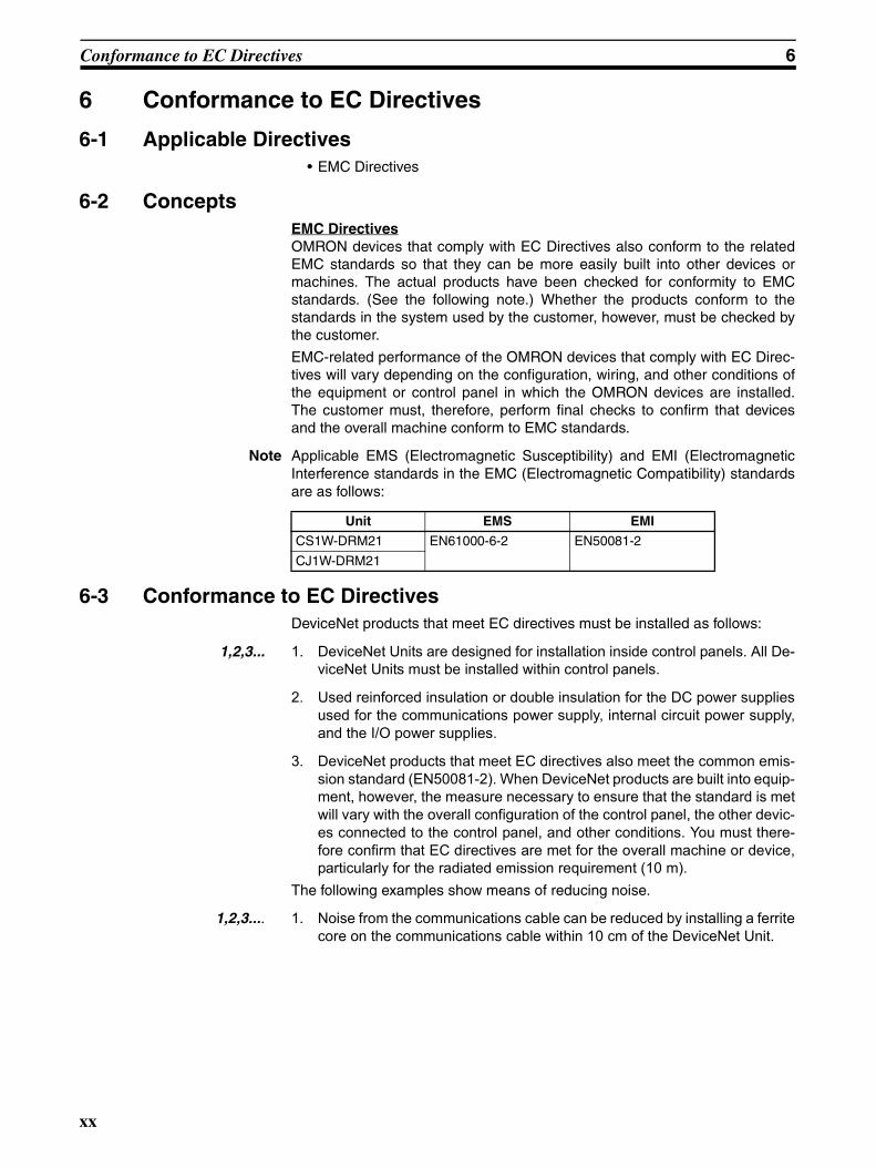
Note Applicable EMS (Electromagnetic Susceptibility) and EMI (ElectromagneticInterference standards in the EMC (Electromagnetic Compatibility) standardsare as follows:
6-3 Conformance to EC DirectivesDeviceNet products that meet EC directives must be installed as follows:
1,2,3... 1. DeviceNet Units are designed for installation inside control panels. All De-viceNet Units must be installed within control panels.
2. Used reinforced insulation or double insulation for the DC power suppliesused for the communications power supply, internal circuit power supply,and the I/O power supplies.
3. DeviceNet products that meet EC directives also meet the common emis-sion standard (EN50081-2). When DeviceNet products are built into equip-ment, however, the measure necessary to ensure that the standard is metwill vary with the overall configuration of the control panel, the other devic-es connected to the control panel, and other conditions. You must there-fore confirm that EC directives are met for the overall machine or device,particularly for the radiated emission requirement (10 m).
The following examples show means of reducing noise.
1,2,3.... 1. Noise from the communications cable can be reduced by installing a ferritecore on the communications cable within 10 cm of the DeviceNet Unit.
Unit EMS EMI
CS1W-DRM21 EN61000-6-2 EN50081-2
CJ1W-DRM21
xx

Conformance to EC Directives 6
2. Wire the control panel with as thick and short electric lines as possible andground to 100 Ω min.
3. Keep DeviceNet communications cables as short as possible and groundto 100 Ω min.
Ferrite Core (Data Line Filter): 0443-164151 (manufactured by Fair-Rite Products Co., Ltd.)
Impedance specifications25 MHZ: 156 Ω100 MHZ: 250 Ω
30 mm
13 mm 29 mm
33 mm
xxi

SECTION 1Features and System Configuration
This section provides an overview of the DeviceNet network, including features, specifications, and system configurations.
1-1 Overview of DeviceNet. . . . . . . . . . . . . . . . . . . . . . . . . . . . . . . . . . . . . . . . . . 2
1-1-1 Overall System Configuration . . . . . . . . . . . . . . . . . . . . . . . . . . . . . 3
1-1-2 Applicable Units and DeviceNet Functions . . . . . . . . . . . . . . . . . . . 6
1-1-3 Masters . . . . . . . . . . . . . . . . . . . . . . . . . . . . . . . . . . . . . . . . . . . . . . . 9
1-1-4 Types of Slave. . . . . . . . . . . . . . . . . . . . . . . . . . . . . . . . . . . . . . . . . . 9
1-1-5 DeviceNet Configurator . . . . . . . . . . . . . . . . . . . . . . . . . . . . . . . . . . 16
1-2 DeviceNet Unit Features . . . . . . . . . . . . . . . . . . . . . . . . . . . . . . . . . . . . . . . . . 16
1-3 Specifications . . . . . . . . . . . . . . . . . . . . . . . . . . . . . . . . . . . . . . . . . . . . . . . . . 22
1-3-1 DeviceNet Unit . . . . . . . . . . . . . . . . . . . . . . . . . . . . . . . . . . . . . . . . . 22
1-3-2 Comparison between CS1W-DRM21(-V1) and CJ1W-DRM21 . . . 29
1-4 Comparison with Previous Models . . . . . . . . . . . . . . . . . . . . . . . . . . . . . . . . . 30
1-5 Outline of the Configurator . . . . . . . . . . . . . . . . . . . . . . . . . . . . . . . . . . . . . . . 34
1-5-1 Models . . . . . . . . . . . . . . . . . . . . . . . . . . . . . . . . . . . . . . . . . . . . . . . 34
1-5-2 Configurator Specifications . . . . . . . . . . . . . . . . . . . . . . . . . . . . . . . 35
1-6 Basic Operating Procedures . . . . . . . . . . . . . . . . . . . . . . . . . . . . . . . . . . . . . . 37
1-6-1 Network Installation Procedure . . . . . . . . . . . . . . . . . . . . . . . . . . . . 37
1-6-2 Hardware Preparations for Communications . . . . . . . . . . . . . . . . . . 37
1-6-3 Creating Routing Tables . . . . . . . . . . . . . . . . . . . . . . . . . . . . . . . . . . 38
1-6-4 Procedures Prior to Starting Communications . . . . . . . . . . . . . . . . . 39
1-7 List of Usage Methods by Purpose . . . . . . . . . . . . . . . . . . . . . . . . . . . . . . . . . 43
1
Overview of DeviceNet Section 1-1
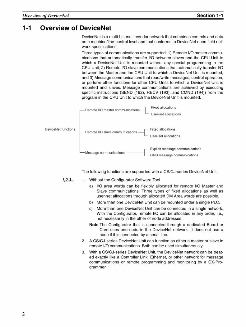
1-1 Overview of DeviceNetDeviceNet is a multi-bit, multi-vendor network that combines controls and dataon a machine/line-control level and that conforms to DeviceNet open field net-work specifications.
Three types of communications are supported: 1) Remote I/O master commu-nications that automatically transfer I/O between slaves and the CPU Unit towhich a DeviceNet Unit is mounted without any special programming in theCPU Unit, 2) Remote I/O slave communications that automatically transfer I/Obetween the Master and the CPU Unit to which a DeviceNet Unit is mounted,and 3) Message communications that read/write messages, control operation,or perform other functions for other CPU Units to which a DeviceNet Unit ismounted and slaves. Message communications are achieved by executingspecific instructions (SEND (192), RECV (193), and CMND (194)) from theprogram in the CPU Unit to which the DeviceNet Unit is mounted.
The following functions are supported with a CS/CJ-series DeviceNet Unit.
1,2,3... 1. Without the Configurator Software Tool
a) I/O area words can be flexibly allocated for remote I/O Master andSlave communications. Three types of fixed allocations as well asuser-set allocations through allocated DM Area words are possible.
b) More than one DeviceNet Unit can be mounted under a single PLC.
c) More than one DeviceNet Unit can be connected in a single network.With the Configurator, remote I/O can be allocated in any order, i.e.,not necessarily in the other of node addresses.
Note The Configurator that is connected through a dedicated Board orCard uses one node in the DeviceNet network. It does not use anode if it is connected by a serial line.
2. A CS/CJ-series DeviceNet Unit can function as either a master or slave inremote I/O communications. Both can be used simultaneously.
3. With a CS/CJ-series DeviceNet Unit, the DeviceNet network can be treat-ed exactly like a Controller Link, Ethernet, or other network for messagecommunications or remote programming and monitoring by a CX-Pro-grammer.
DeviceNet functions
Remote I/O master communications
Remote I/O slave communications
Message communications
Fixed allocations
User-set allocations
Fixed allocations
User-set allocations
Explicit message communications
FINS message communications
2
Overview of DeviceNet Section 1-1
1-1-1 Overall System Configuration
Note The Configurator is required if more than one Master is connected in a singlenetwork when a CVM1-DRM21-V1 or C200HW-DRM21-V1 is used.
Master Features
DeviceNet Master Units and DeviceNet Units
Support remote I/O communications between OMRON PLCs (CS-series, CJ-series, CVM1, CV-series, or C200HX/HG/HE/HS) and slaves.
Support message communications between OMRON PLCs, or between anOMRON PLC and slaves and masters from other companies.
VME Master Boards
Supports remote I/O communications between a VME System and slaves.
DeviceNet Unit or DeviceNet Master Unit
CS Series
CS1W-DRM21(-V1)
CVM1/CV Series: CVM1-DRM21-V1
C200HZ/HX/HG/E/HS: C200HW-DRM21-V1 Photoelectric
sensors, proximi-ty sensors, limit switches, etc.
Photoelectric sensors or prox-imity sensors with connectors
DeviceNet Configurator (personal com-puter)
Photoelectric sensors, proximi-ty sensors, limit switches, etc.
Photoelectric sensors, proximity sensors, limit switches, etc.
Solenoids, valves, etc.
I/O Link UnitCQM1
Solenoids, valves, etc.
Solenoids, valves, etc.
Output Terminal
Output Remote Adapter (used with Output Block)
Input Terminal
Sensor Terminal
Environment-re-sistant Terminal(Inputs, outputs, or mixed I/O)
: T-branch Taps or multi-drop connections
Analog Input Terminal
Analog Output Terminal
DeviceNet Unit or DeviceNet Master Unit
Inputs Outputs Outputs
MULTIPLE I/O TERMINAL
Temper-ature In-put Ter-minal
Thermocouple, platinum resistance thermometer
C200H I/O Link Unit
RS-232C Unit
Bar code readers, etc.
Inverters, valves, etc.
Analog sensors, etc.
(See note.)
Inputs
CJ Series CJ1W-DRM21
Input Remote Adapter (used with Input Block)
3
Overview of DeviceNet Section 1-1
Configurator Features• Enables user-set allocations for remote I/O (choice of node address order,
2 area allocations, etc.).
• Enables serial connection to the Programming Device Port of a PLC.
• Enables user settings for DeviceNet remote I/O communications connec-tions.
• Enables multiple Masters on a single PLC.
• Enables multiple Masters in a single network.
Slave Features
I/O Terminals
• Provide general-purpose I/O via terminal blocks (M3).
• Available in the following models:
• 8-point Transistor Input Terminal
• 16-point Transistor Input Terminal
• 8-point Transistor Output Terminal
• 16-point Transistor Output Terminal
Environment-resistant Terminals
• Improved I/O Terminals that conform to IP66 for spatter-, water-, and oil-resistance.
• Available in the following models:
• 8-point Transistor Input Terminal
• 8-point Transistor Output Terminal
• 16-point Transistor I/O Terminal (8 inputs and 8 outputs)
Remote Adapters
• Used in combination with G70D and other I/O Blocks to handle relay out-puts, power MOS FET Relay outputs, etc.
• Available in 16-point input and 16-point output models.
I/O Link Units
• More than one I/O Link Unit can be mounted to a CQM1 PLC.
• Link 16 inputs and 16 outputs between the PLC and the Master.
Sensor Terminals
• Accept inputs from photoelectric and proximity sensors with connectors.
• Available in 16-point input and 8-point input/8-point output models.
• Output signals can be used for sensor teaching and external diagnosis.
Analog Input Terminals
• Convert analog inputs to binary.
• Switchable between 2 and 4 input points using the DIP switch.
• Handle inputs of 0 to 5 V, 1 to 5 V, 0 to 10 V, –10 to +10 V, 0 to 20 mA, or4 to 20 mA.
• Available in models with a resolution of either 1/6,000 or 1/3,000.
Analog Output Terminals
• Convert binary data to analog outputs.
• Provides outputs of 1 to 5 V, 0 to 10 V, –10 to +10 V, 0 to 20 mA, or 4 to20mA.
4

Overview of DeviceNet Section 1-1
• Available in models with a resolution of 1/6,000.
Temperature Input Terminals
• Temperature data is input as binary data for 4 inputs.
• Thermocouple and platinum resistance thermometer inputs are available.
C200H I/O Link Units
• Special I/O Slaves that mount to C200HX/HG/HE PLCs and read/writedata from the Master to the specified words in the CPU Unit.
• Read and write areas specified for up to 512 bits each (32 words each).
• Any memory area words can be read or written using DeviceNet explicitmessages.
RS-232C Units
• Special I/O Slaves that provide two RS-232C ports and control I/O fromthe Masters.
MULTIPLE I/O TERMINALs
• Multiple I/O Units can be combined under a Communications Unit andtreated as a single Slave.
• Special I/O Units, such as Analog I/O Units, and High-speed CounterUnits are also available.
5
Overview of DeviceNet Section 1-1
1-1-2 Applicable Units and DeviceNet FunctionsRemote I/O Master
DeviceNet Unit (Master)CPU Unit
Remote I/O communications
DeviceNet
Slaves
Item Master Model Without Configurator With Configurator
Max. No. of Slave nodes per Master
CS Series CS1W-DRM21(-V1) 63 nodes
CJ Series CJ1W-DRM21
CVM1, CV Series CVM1-DRM21-V1
CS Series, C200HX/HG/HE
C200HW-DRM21-V1 50 nodes 63 nodes
C200HS 32 nodes 63 nodes
Max. No. of control points per Master
CS Series CS1W-DRM21(-V1) 2,048 pts (64 input /64 output words) or 16,000 pts (500 input/500 output words)
32,000 pts (500 words x 4 blocks)
CJ Series CJ1W-DRM21
CVM1, CV Series CVM1-DRM21-V1 2,048 pts (64 input/ 64 output words)
6,400 (100 words x 4 blocks
CS Series, C200HX/HG/HE
C200HW-DRM21-V1 1,600 pts (50 input/50 output words)
Without messages:4,800 ptsWith messages:1,600 pts
C200HS 1,024 pts (32 input/32 output words)
1,280
Max. No. of I/O points per Slave con-trollable by Master
CS Series CS1W-DRM21(-V1) 100 input/100 output words
CJ Series CJ1W-DRM21
CVM1, CV Series CVM1-DRM21-V1 32 input/32 output words
CS Series, C200HX/HG/HE
C200HW-DRM21-V1
C200HS
Remote I/O alloca-tion areas
CS Series CS1W-DRM21(-V1) CS/CJ DeviceNet words in CIO Area, and user-allocated words in CIO Area, DM Area, and other areas.
User-allocated words in CIO Area, DM Area, and other areas.CJ Series CJ1W-DRM21
CVM1, CV Series CVM1-DRM21-V1 DeviceNet Area User-allocated words in CIO Area, DM Area, and other areas.
CS Series, C200HX/HG/HE
C200HW-DRM21-V1 C200H DeviceNet words in CIO Area (including dedicated words/ bits)
C200HS
6
Overview of DeviceNet Section 1-1
Remote I/O Slave (only Units Mounted in a PLC)DeviceNet Unit (Master)
CPU Unit IN area OUT area
Remote I/O communicationsDeviceNet
DeviceNet Unit (Slave)CPU Unit
IN area OUT area
Slaves
Item CPU Unit to which a Slave is
mounted
Unit Model Without the Configurator
With the Configurator
Max. No. of I/O pts per Slave
CS Series CS1W-DRM21(-V1) 32 pts (1 input/ 1 output word) or 3,200 pts (100 input/100 output words)
4,800 pts (100 input words x 2/100 output words x 1)CJ Series CJ1W-DRM21
CS Series, C200HX/HG/HE
C200HW-DRT21 1,024 pts (32 input/32 output words)
CQM1HCQM1 Series
CQM1-DRT21 32 pts (1 input/1 output word)
Allocation areas in the CPU Unit to which this Slave is mounted
CS Series CS1W-DRM21(-V1) CIO, WR, DM, EM, HR
CJ Series CJ1W-DRM21
CS Series, C200HX/HG/HE
C200HW-DRT21 CIO, DM, EM, AR, LR, T/C
CQM1HCQM1 Series
CQM1-DRT21 CIO
7
Overview of DeviceNet Section 1-1
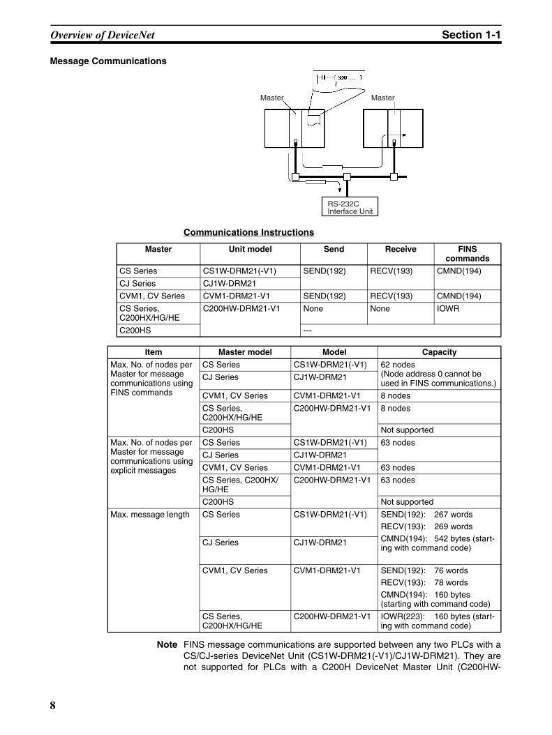
Message Communications
Communications Instructions
Note FINS message communications are supported between any two PLCs with aCS/CJ-series DeviceNet Unit (CS1W-DRM21(-V1)/CJ1W-DRM21). They arenot supported for PLCs with a C200H DeviceNet Master Unit (C200HW-
Master Master
RS-232C Interface Unit
Master Unit model Send Receive FINS commands
CS Series CS1W-DRM21(-V1) SEND(192) RECV(193) CMND(194)
CJ Series CJ1W-DRM21
CVM1, CV Series CVM1-DRM21-V1 SEND(192) RECV(193) CMND(194)
CS Series,C200HX/HG/HE
C200HW-DRM21-V1 None None IOWR
C200HS ---
Item Master model Model Capacity
Max. No. of nodes per Master for message communications using FINS commands
CS Series CS1W-DRM21(-V1) 62 nodes (Node address 0 cannot be used in FINS communications.)
CJ Series CJ1W-DRM21
CVM1, CV Series CVM1-DRM21-V1 8 nodes
CS Series, C200HX/HG/HE
C200HW-DRM21-V1 8 nodes
C200HS Not supported
Max. No. of nodes per Master for message communications using explicit messages
CS Series CS1W-DRM21(-V1) 63 nodes
CJ Series CJ1W-DRM21
CVM1, CV Series CVM1-DRM21-V1 63 nodes
CS Series, C200HX/HG/HE
C200HW-DRM21-V1 63 nodes
C200HS Not supported
Max. message length CS Series CS1W-DRM21(-V1) SEND(192): 267 wordsRECV(193): 269 words
CMND(194): 542 bytes (start-ing with command code)
CJ Series CJ1W-DRM21
CVM1, CV Series CVM1-DRM21-V1 SEND(192): 76 wordsRECV(193): 78 words
CMND(194): 160 bytes(starting with command code)
CS Series, C200HX/HG/HE
C200HW-DRM21-V1 IOWR(223): 160 bytes (start-ing with command code)
8
Overview of DeviceNet Section 1-1
DRM21-V1) or a CVM1/CV-series DeviceNet Master Unit (CVM1-DRM21-V1). Refer to 6-3 Using FINS Message Communications for details.
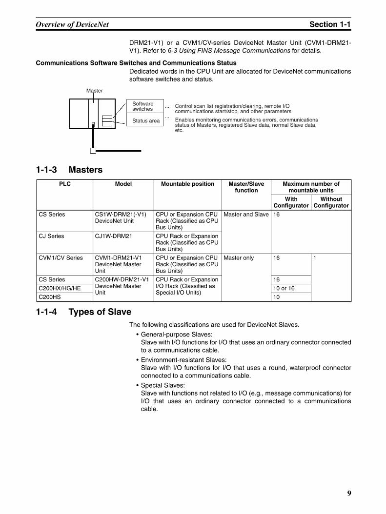
Communications Software Switches and Communications StatusDedicated words in the CPU Unit are allocated for DeviceNet communicationssoftware switches and status.
1-1-3 Masters
1-1-4 Types of SlaveThe following classifications are used for DeviceNet Slaves.
• General-purpose Slaves:Slave with I/O functions for I/O that uses an ordinary connector connectedto a communications cable.
• Environment-resistant Slaves:Slave with I/O functions for I/O that uses a round, waterproof connectorconnected to a communications cable.
• Special Slaves:Slave with functions not related to I/O (e.g., message communications) forI/O that uses an ordinary connector connected to a communicationscable.
PLC Model Mountable position Master/Slave function
Maximum number of mountable units
With Configurator
Without Configurator
CS Series CS1W-DRM21(-V1) DeviceNet Unit
CPU or Expansion CPU Rack (Classified as CPU Bus Units)
Master and Slave 16
CJ Series CJ1W-DRM21 CPU Rack or Expansion Rack (Classified as CPU Bus Units)
CVM1/CV Series CVM1-DRM21-V1 DeviceNet Master Unit
CPU or Expansion CPU Rack (Classified as CPU Bus Units)
Master only 16 1
CS Series C200HW-DRM21-V1 DeviceNet Master Unit
CPU Rack or Expansion I/O Rack (Classified as Special I/O Units)
16
C200HX/HG/HE 10 or 16
C200HS 10
Master
Control scan list registration/clearing, remote I/O communications start/stop, and other parameters
Software switches
Enables monitoring communications errors, communications status of Masters, registered Slave data, normal Slave data, etc.
Status area
9
Overview of DeviceNet Section 1-1
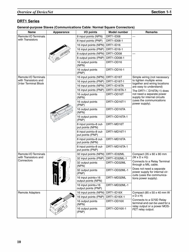
DRT1 Series
General-purpose Slaves (Communications Cable: Normal Square Connectors)Name Appearance I/O points Model number Remarks
Remote I/O Terminals with Transistors
8 input points (NPN) DRT1-ID08 ---
8 input points (PNP) DRT1-ID08-1
16 input points (NPN) DRT1-ID16
16 input points (PNP) DRT1-ID16-1
8 output points (NPN) DRT1-OD08 ---
8 output points (PNP) DRT1-OD08-1
16 output points (NPN)
DRT1-OD16
16 output points (PNP)
DRT1-OD16-1
Remote I/O Terminals with Transistors and 3-tier Terminal Block
16 input points (NPN) DRT1-ID16T Simple wiring (not necessary to tighten multiple wires together and wiring locations are easy to understand)
The DRT1-@D16TA(-1) does not need a separate power supply for internal circuits (uses the communications power supply).
16 input points (PNP) DRT1-ID16T-1
16 input points (NPN) DRT1-ID16TA
16 input points (PNP) DRT1-ID16TA-1
16 output points (NPN)
DRT1-OD16T
16 output points (PNP)
DRT1-OD16T-1
16 output points (NPN)
DRT1-OD16TA
16 output points (PNP)
DRT1-OD16TA-1
8 input points+8 out-put points (NPN)
DRT1-MD16T
8 input points+8 out-put points (PNP)
DRT1-MD16T-1
8 input points+8 out-put points (NPN)
DRT1-MD16TA
8 input points+8 out-put points (PNP)
DRT1-MD16TA-1
Remote I/O Terminals with Transistors and Connectors
32 input points (NPN) DRT1-ID32ML Compact (35 x 60 x 80 mm (W x D x H))Connects to a Relay Terminal through a MIL cable.
Does not need a separate power supply for internal cir-cuits (uses the communica-tions power supply).
32 input points (PNP) DRT1-ID32ML-1
32 output points (NPN)
DRT1-OD32ML
32 output points (PNP)
DRT1-OD32ML-1
16 input points+16 output points (NPN)
DRT1-MD32ML
16 input points+16 output points (PNP)
DRT1-MD32ML-1
Remote Adapters 16 input points (NPN) DRT1-ID16X Compact (85 x 50 x 40 mm W x D x H)Connects to a G70D Relay terminal and can be used for a relay output or a power MOS-FET relay output.
16 input points (PNP) DRT1-ID16X-1
16 output points (NPN)
DRT1-OD16X
16 output points (PNP)
DRT1-OD16X-1
10
Overview of DeviceNet Section 1-1
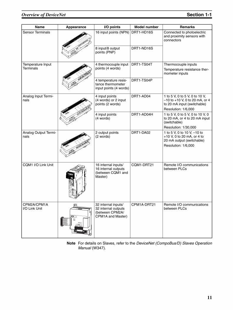
Note For details on Slaves, refer to the DeviceNet (CompoBus/D) Slaves OperationManual (W347).
Sensor Terminals 16 input points (NPN) DRT1-HD16S Connected to photoelectric and proximity sensors with connectors
8 input/8 output points (PNP)
DRT1-ND16S
Temperature Input Terminals
4 thermocouple input points (4 words)
DRT1-TS04T Thermocouple inputsTemperature resistance ther-mometer inputs
4 temperature resis-tance thermometer input points (4 words)
DRT1-TS04P
Analog Input Termi-nals
4 input points (4 words) or 2 input points (2 words)
DRT1-AD04 1 to 5 V, 0 to 5 V, 0 to 10 V, –10 to +10 V, 0 to 20 mA, or 4 to 20 mA input (switchable)Resolution: 1/6,000
4 input points (4 words)
DRT1-AD04H 1 to 5 V, 0 to 5 V, 0 to 10 V, 0 to 20 mA, or 4 to 20 mA input (switchable)
Resolution: 1/30,000
Analog Output Termi-nals
2 output points (2 words)
DRT1-DA02 1 to 5 V, 0 to 10 V, –10 to +10 V, 0 to 20 mA, or 4 to 20 mA output (switchable)Resolution: 1/6,000
CQM1 I/O Link Unit 16 internal inputs/ 16 internal outputs (between CQM1 and Master)
CQM1-DRT21 Remote I/O communications between PLCs
CPM2A/CPM1A I/O Link Unit
32 internal inputs/ 32 internal outputs (between CPM2A/CPM1A and Master)
CPM1A-DRT21 Remote I/O communications between PLCs
Name Appearance I/O points Model number Remarks
11
Overview of DeviceNet Section 1-1
Waterproof and Environment-resistant Slaves (Communications Cable: Round Connectors)
Special Slaves (Communications Cable: Normal Square Connectors)
Name Appearance I/O points Model number Remarks
Waterproof Terminals 4 input points (NPN) DRT1-ID04CL Dust and drip-proof structure for environmental resistance (IP 67)XS2 Series connector system eliminates the need for tools for sensor, valve or other con-nections.
4 input points (PNP) DRT1-ID04CL-1
8 input points (NPN) DRT1-ID08CL
8 input points (PNP) DRT1-ID08CL-1
4 output points (NPN) DRT1-OD04CL
4 output points (PNP) DRT1-OD04CL-1
8 output points (NPN) DRT1-OD08CL
8 output points (PNP) DRT1-OD08CL-1
Environment-resis-tant Terminals
8 input points (NPN) DRT1-ID08C Spatter, dust and drip-proof structure for environmental resistance (IP 66)XS2 Series connector system eliminates the need for tools for sensor, valve or other con-nections.
8 output points (NPN) DRT1-OD08C
16 input points (NPN) DRT1-HD16C
16 input points (PNP) DRT1-HD16C-1
16 output points (NPN)
DRT1-WD16C
16 output points (PNP)
DRT1-WD16C-1
8 input points+8 out-put points (NPN)
DRT1-MD16C
8 input points+8 out-put points (PNP)
DRT1-MD16C-1
B7AC Interface Ter-minal
10 input points x 3 DRT1-B7AC Splits 1 B7AC Unit into 3 branches.XS2 Series connector system eliminates the need for tools.
Dust and drip-proof structure for environmental resistance (IP 66)
Name Appearance I/O points Model number Remarks
C200H I/O Link Unit 512 inputs max. (32 words)512 outputs max. (32 words)
C200HW-DRT21 Supports remote I/O and message communications between PLCs.Max. I/O area: 512 input points and 52 output points
Any I/O words can be allo-cated.
RS-232C Unit 16 inputs (1 word) DRT1-232C2 Two RS-232C ports mounted
Data sent and received by explicit message (151 bytes max.)
Executes settings and control through explicit messages.Reflects RS-232C port status in the input.
Programmable Slaves
512 inputs max. (32 words)512 outputs max. (32 words)
CPM2C-S100C-DRT
CPM2C-S110C-DRT
Controller that enables com-munications with CompoBus/S Master.Enables message communi-cations using explicit mes-sages.
12
Overview of DeviceNet Section 1-1
DRT2 Series
General-purpose Slaves (Communications Cable: Normal Square Connectors)
Environment-resistant Slaves (Communications Cable: Round Waterproof Connectors)
Analog Slaves (Communications Cable: Normal Square Connectors)
Name Appearance I/O points Model number Remarks
Remote I/O Terminals with Transistors
16 input points (NPN)
DRT2-ID16 Terminal block mounted/removed using screws.
16 input points (PNP) DRT2-ID16-1
16 output points (NPN)
DRT2-OD16
16 output points (PNP)
DRT2-OD16-1
Remote I/O Terminal Expansion Units with Transistors
16 input points (NPN)
XWT-ID16 Expansion Unit for increasing inputs or outputs of the Basic Unit.
16 input points (PNP) XWT-ID16-1
16 output points (NPN)
XWT-OD16
16 output points (PNP)
XWT-OD16-1
8 input points (NPN) XWT-ID08
8 input points (PNP) XWT-ID08-1
8 output points (NPN)
XWT-OD08
8 output points (PNP)
XWT-OD08-1
Name Appearance I/O points Model number Remarks
Environment-resistive Terminals
8 input points (NPN) DRT2-ID08C Waterproof, oil-proof, and spatter-proof construction (IP67).
8 input points (PNP) DRT2-ID08C-1
16 input points (NPN)
DRT2-HD16C
16 input points (PNP) DRT2-HD16C-1
8 output points (NPN)
DRT2-OD08C
8 output points (PNP)
DRT2-OD08C-1
Name Appearance I/O points Model number Remarks
Analog Terminals 4 input points (0 to 5 V, 1 to 5 V, 0 to 10 V, −10 to 10 V, 0 to 20 mA, 4 to 20 mA)
DRT2-AD04 Terminal block mounted/removed using screws.
2 output points (0 to 5 V, 1 to 5 V, 0 to 10 V, −10 to 10 V, 0 to 20 mA, 4 to 20 mA)
DRT2-DA02
13

Overview of DeviceNet Section 1-1
MULTIPLE I/O TERMINAL UnitsUnit I/O
pointsWords allocated in PC memory
I/O connec-tions
Unit power supply voltage
Installa-tion
Modelnumber
Remarks
Input Output
Communications Unit None Two sta-tus words
0 words None 24 VDC (sup-plied from out-side)
DIN track DRT1-COM ---
Basic I/O Units
Transistor Input Units
16 input points
1 word 0 words M3 terminal block
GT1-ID16 NPN
GT1-ID16-1 PNP
16 input points
1 word 0 words Connector (made by MOLEX)
GT1-ID16MX NPN
GT1-ID16MX-1 PNP
16 input points
1 word 0 words Connector (made by FUJITSU)
GT1-ID16ML NPN
GT1-ID16ML-1 PNP
16 input points
1 word 0 words Connector (D-sub, 25 pin)
GT1-ID16DS NPN
GT1-ID16DS-1 PNP
32 input points
2 words 0 words High-den-sity connec-tor (made by FUJITSU)
GT1-ID32ML NPN
GT1-ID32ML-1 PNP
Transistor Output Units
16 out-put points
0 words 1 word M3 terminal block
GT1-OD16 NPN
GT1-OD16-1 PNP
16 out-put points
0 words 1 word Connector (made by MOLEX)
GT1-OD16MX NPN
GT1-OD16MX-1 PNP
16 out-put points
0 words 1 word Connector (made by FUJITSU)
GT1-OD16ML NPN
GT1-OD16ML-1 PNP
16 out-put points
0 words 1 word Connector (D-sub, 25 pin)
GT1-OD16DS NPN
GT1-OD16DS-1 PNP
32 out-put points
0 words 2 words High-den-sity connec-tor (made by FUJITSU)
GT1-OD32ML NPN
GT1-OD32ML-1 PNP
Relay Out-put Units
16 out-put points
0 words 1 word M3 terminal block
GT1-ROS16 ---
8 out-put points
0 words 1 word GT1-ROP08 ---
14

Overview of DeviceNet Section 1-1
Note The front-panel indicators and other parts of Analog Input Units, Analog Out-put Units, and Counter Units differ from those of other I/O Units. These Unitsbelong to a group called Special I/O Units.
One I/O Unit Connecting Cable (cable length 40 mm) is included with each I/OUnit. One end connector is attached to the Communications Unit.
I/O Unit Connecting Cables with a cable lengths of 0.1, 0.3, 0.4, 0.6, and 1 m(GCN1-010/030/040/060/100) are sold separately (see below).
Note For details on MULTIPLE I/O TERMINAL Units, refer to the DeviceNet MULTI-PLE I/O TERMINAL Operation Manual (W348).
Special I/O Units(See note.)
Analog Input Units
4 inputs 4 words 0 words M3 terminal block
24 VDC (sup-plied from out-side)
DIN track GT1-AD04 Inputs: 4 to 20 mA, 0 to 20 mA, 0 to 5 V, 1 to 5 V, 0 to 10 V, –10 to 10 V
8 inputs 8 words 0 words Connector (made by MOLEX)
GT1-AD08MX
Analog Output Units
4 out-puts
0 words 4 words M3 terminal block
GT1-DA04 Outputs: 4 to 20 mA0 to 5 V, 1 to 5 V, 0 to 10 V, –10 to 10 V
4 out-puts
0 words 4 words Connector (made by MOLEX)
GT1-DA04MX Outputs: 0 to 5 V, 1 to 5 V, 0 to 10 V, –10 to 10 V
Tempera-ture Input Unit
4 inputs 4 or 8 words (varies with data for-mat)
0 words M3 terminal block
GT1-TS04T Sensor types: R, S, K, J, T, B, L
4 inputs 0 words M3 terminal block
GT1-TS04P Sensor types: Pt100, JPt100
Counter Unit
1 input 3 words 3 words M3 terminal block
GT1-CT01 1 external input2 external outputs
Unit I/O points
Words allocated in PC memory
I/O connec-tions
Unit power supply voltage
Installa-tion
Modelnumber
Remarks
Input Output
Length
15
DeviceNet Unit Features Section 1-2
1-1-5 DeviceNet ConfiguratorUse version 2 of the DeviceNet Configurator for the CS1W-DRM21(-V1)/CJ1W-DRM21 DeviceNet Unit. Earlier versions of the DeviceNet Configuratordo not support the CS1W-DRM21 DeviceNet Unit.
Note The following Boards and Cards can be used.
Note Use DeviceNet Configurator version 2.10 or later for the CJ1W-DRM21.
1-2 DeviceNet Unit FeaturesThe following are features of the CS-series and CJ-series DeviceNet Units(CS1W-DRM21(-V1) and CJ1W-DRM21).
Multi-vendor Network Devices made by other companies (masters or slaves) can be connected toDeviceNet because it conforms to open field network specifications. By usinga combination of valves, sensors, and other DeviceNet products, the networkcan be adapted to various field-level applications.
Simultaneous Remote I/O Communications and Messaging Services
Remote I/O communications that constantly transfer I/O between a DeviceNetUnit and slaves as well as message communications where the DeviceNetUnit sends and receives data as needed can both be executed simulta-neously. When a DeviceNet network is constructed, this feature ensures thenetwork will be able to handle applications that require the free flow back andforth of bit data and message data. FINS commands can be executed alongwith DeviceNet explicit messages in message communications.
Remote I/O Communications
Note Refer to SECTION 4 Remote I/O Master Communications for details onremote I/O communications.
Product name
Model Components Network connection to computer
Applicable computer
OS
DeviceNet Configurator (Ver. 2)
WS02-CFDC1-E Installation disk (CD-ROM)
Any of the following:
• Serial connection• PCMCIA Card• ISA Board(See the table below.)
IBM PC/AT or compatible
Windows 95, 98, Me, NT4.0, or 2000
Model Components Applicable computer
OS
3G8F5-DRM21 Dedicated ISA Board with DeviceNet Configurator (Ver. 2)
IBM PC/AT or compatible
Windows 95, 98, or NT4.0
3G8E2-DRM21 Dedicated PCMCIA Card with DeviceNet Configurator (Ver. 2)
Windows 95 or 98
DeviceNet
CS/CJ-series DeviceNet Unit (master)
Remote I/O (master) function
Slave SlaveSlave
16
DeviceNet Unit Features Section 1-2
Explicit Message Communications
Note Refer to 6-4 Sending Explicit Messages for details on remote I/O communica-tions.
FINS Message Communications
Note Refer to 6-3 Using FINS Message Communications for details on FINS com-munications.
User-set allocations without the Configurator
With CS/CJ-series DeviceNet Units, remote I/O communications can be allo-cated in any area without the Configurator simply by using DM Area settings.If the Configurator is used, it allows you to change the node address order formore flexible I/O allocations. This feature ensures the proper I/O allocationsfor any application and it makes effective use of PLC memory by simplifyingprogramming.
Note Refer to 4-4 User-set Allocations for details.
Slave Functions CS/CJ-series DeviceNet Units can be used as both masters and slaves, andmaster and slave communications can be executed either separately or simul-
DeviceNet
CS/CJ-series DeviceNet Unit
Explicit message
RS-232C Slave
RS-232C Slave
CS/CJ-series DeviceNet Unit
DeviceNet
CS/CJ-series DeviceNet Unit
FINS message
Slave Slave
CS/CJ-series DeviceNet Unit
17
DeviceNet Unit Features Section 1-2
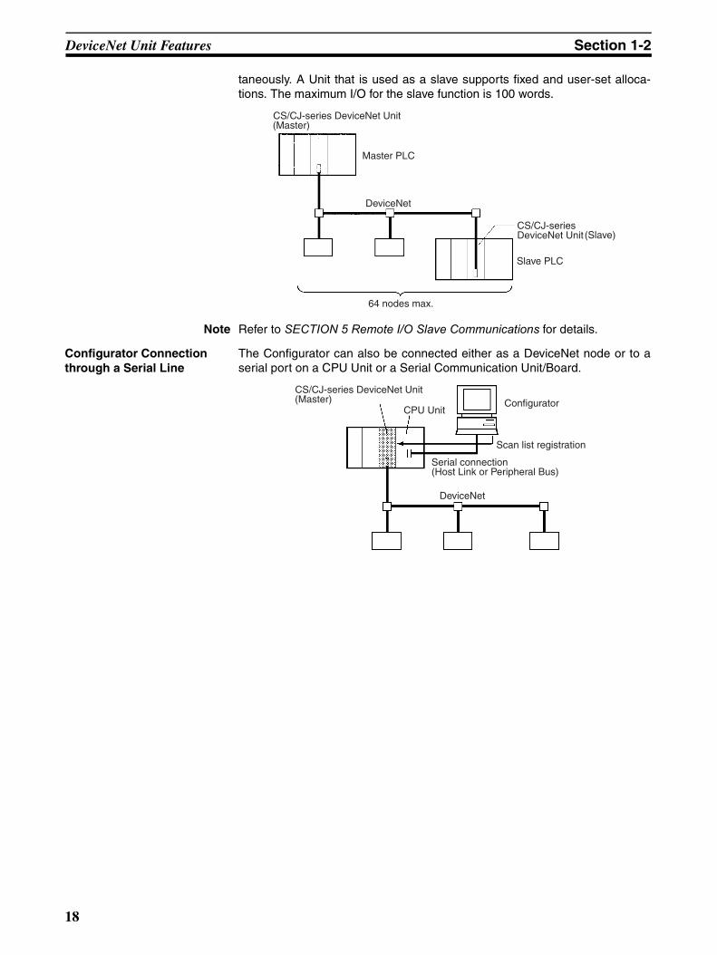
taneously. A Unit that is used as a slave supports fixed and user-set alloca-tions. The maximum I/O for the slave function is 100 words.
Note Refer to SECTION 5 Remote I/O Slave Communications for details.
Configurator Connection through a Serial Line
The Configurator can also be connected either as a DeviceNet node or to aserial port on a CPU Unit or a Serial Communication Unit/Board.
CS/CJ-series DeviceNet Unit (Master)
Master PLC
DeviceNet
64 nodes max.
(Slave)
Slave PLC
CS/CJ-series DeviceNet Unit
CS/CJ-series DeviceNet Unit (Master)
CPU UnitConfigurator
Scan list registration
Serial connection (Host Link or Peripheral Bus)
DeviceNet
18

DeviceNet Unit Features Section 1-2
CX-Programmer Programming and Monitoring of DeviceNet Slave PLCs (Ver. 2.1 or Later)
CX-Programmer Ver. 2.1 connected to a serial communications port on aDeviceNet PLC can be used to remotely program and monitor otherDeviceNet PLCs (i.e., PLCs with a CS/CJ-series DeviceNet Unit or a Pro-grammable Slave).
Note Refer to 7-1 Connecting to the CX-Programmer via the DeviceNet for details.
Inter-network Connections FINS messages can be sent back and forth between DeviceNet and othernetworks (e.g., Controller Link, SYSMAC LINK, and Ethernet). This featureenables seamless message communications between all types of networks,including DeviceNet.
Note Refer to 6-3 Using FINS Message Communications for details.
CX-Programmer
DeviceNet
CX-Programmer
DeviceNetEthernet
CS/CJ-series DeviceNet Unit (master)
CS/CJ-series DeviceNet Unit (master)
CS/CJ-series DeviceNet Unit (master)
CS/CJ-series DeviceNet Unit (master)
Program-mable Slave
Program-mable Slave
Serial line (Host Link or peripheral bus)
CS/CJ-series Ethernet Unit
Controller Link UnitController Link Unit
CS/CJ-series DeviceNet Unit
FINS messageController Link
DeviceNet
CS/CJ-series DeviceNet Unit
19
DeviceNet Unit Features Section 1-2
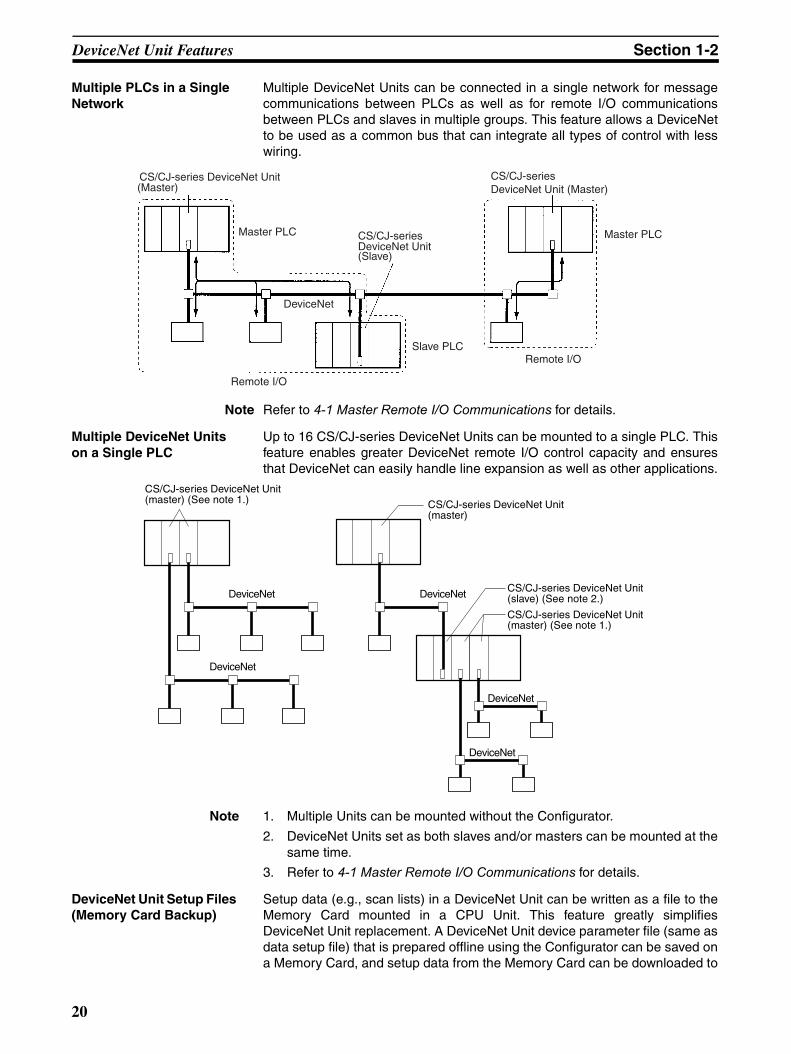
Multiple PLCs in a Single Network
Multiple DeviceNet Units can be connected in a single network for messagecommunications between PLCs as well as for remote I/O communicationsbetween PLCs and slaves in multiple groups. This feature allows a DeviceNetto be used as a common bus that can integrate all types of control with lesswiring.
Note Refer to 4-1 Master Remote I/O Communications for details.
Multiple DeviceNet Units on a Single PLC
Up to 16 CS/CJ-series DeviceNet Units can be mounted to a single PLC. Thisfeature enables greater DeviceNet remote I/O control capacity and ensuresthat DeviceNet can easily handle line expansion as well as other applications.
Note 1. Multiple Units can be mounted without the Configurator.
2. DeviceNet Units set as both slaves and/or masters can be mounted at thesame time.
3. Refer to 4-1 Master Remote I/O Communications for details.
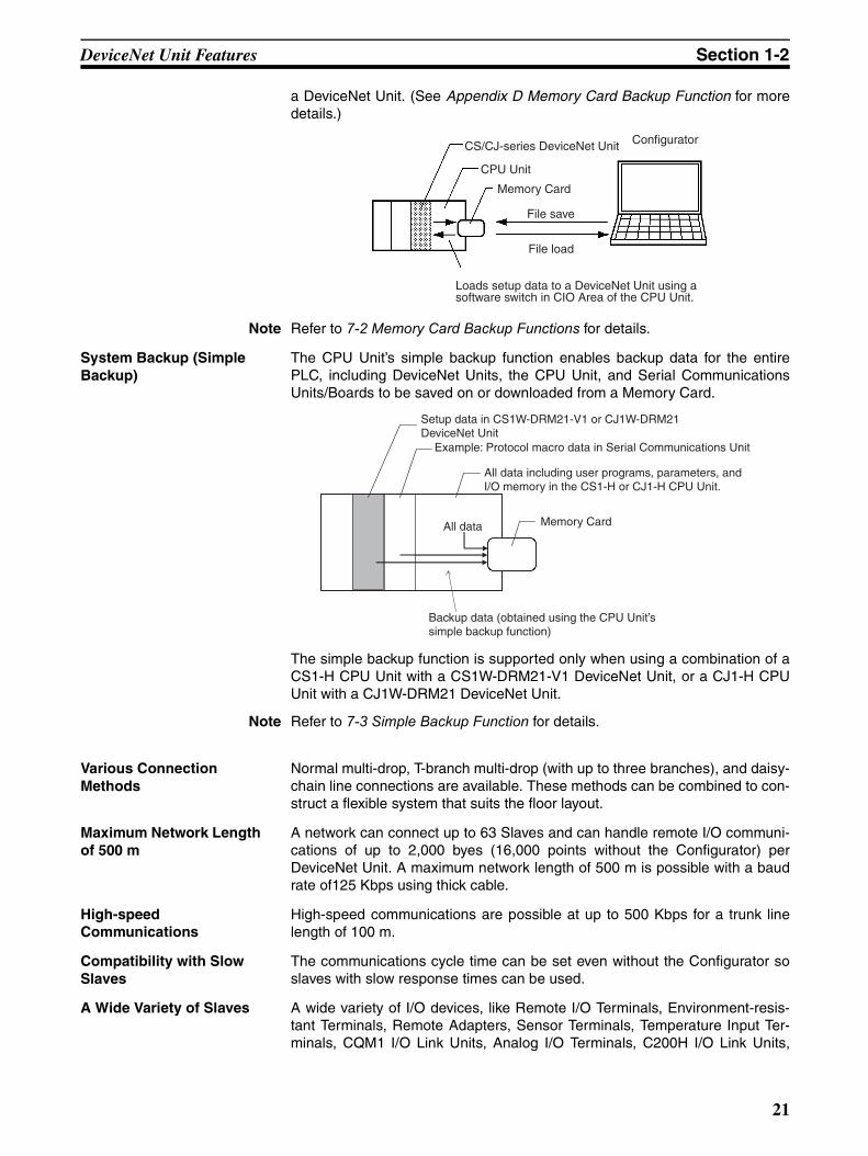
DeviceNet Unit Setup Files (Memory Card Backup)
Setup data (e.g., scan lists) in a DeviceNet Unit can be written as a file to theMemory Card mounted in a CPU Unit. This feature greatly simplifiesDeviceNet Unit replacement. A DeviceNet Unit device parameter file (same asdata setup file) that is prepared offline using the Configurator can be saved ona Memory Card, and setup data from the Memory Card can be downloaded to
CS/CJ-series DeviceNet Unit (Master)
Master PLC
(Slave)
Master PLC
Remote I/OSlave PLC
Remote I/O
DeviceNet
CS/CJ-series DeviceNet Unit (Master)
CS/CJ-series DeviceNet Unit
DeviceNet
DeviceNet
DeviceNet
DeviceNet
DeviceNet
CS/CJ-series DeviceNet Unit (master) (See note 1.) CS/CJ-series DeviceNet Unit
(master)
CS/CJ-series DeviceNet Unit (slave) (See note 2.)
CS/CJ-series DeviceNet Unit (master) (See note 1.)
20
DeviceNet Unit Features Section 1-2
a DeviceNet Unit. (See Appendix D Memory Card Backup Function for moredetails.)
Note Refer to 7-2 Memory Card Backup Functions for details.
System Backup (Simple Backup)
The CPU Unit’s simple backup function enables backup data for the entirePLC, including DeviceNet Units, the CPU Unit, and Serial CommunicationsUnits/Boards to be saved on or downloaded from a Memory Card.
The simple backup function is supported only when using a combination of aCS1-H CPU Unit with a CS1W-DRM21-V1 DeviceNet Unit, or a CJ1-H CPUUnit with a CJ1W-DRM21 DeviceNet Unit.
Note Refer to 7-3 Simple Backup Function for details.
Various Connection Methods
Normal multi-drop, T-branch multi-drop (with up to three branches), and daisy-chain line connections are available. These methods can be combined to con-struct a flexible system that suits the floor layout.
Maximum Network Length of 500 m
A network can connect up to 63 Slaves and can handle remote I/O communi-cations of up to 2,000 byes (16,000 points without the Configurator) perDeviceNet Unit. A maximum network length of 500 m is possible with a baudrate of125 Kbps using thick cable.
High-speed Communications
High-speed communications are possible at up to 500 Kbps for a trunk linelength of 100 m.
Compatibility with Slow Slaves
The communications cycle time can be set even without the Configurator soslaves with slow response times can be used.
A Wide Variety of Slaves A wide variety of I/O devices, like Remote I/O Terminals, Environment-resis-tant Terminals, Remote Adapters, Sensor Terminals, Temperature Input Ter-minals, CQM1 I/O Link Units, Analog I/O Terminals, C200H I/O Link Units,
CS/CJ-series DeviceNet Unit
CPU Unit
Memory Card
File save
File load
Configurator
Loads setup data to a DeviceNet Unit using a software switch in CIO Area of the CPU Unit.
Setup data in CS1W-DRM21-V1 or CJ1W-DRM21 DeviceNet Unit
Example: Protocol macro data in Serial Communications Unit
All data including user programs, parameters, and I/O memory in the CS1-H or CJ1-H CPU Unit.
All data Memory Card
Backup data (obtained using the CPU Unit’s simple backup function)
21
Specifications Section 1-3
RS-232C Units, MULTIPLE I/O TERMINALs, Temperature Adjusters, Invert-ers, and Intelligent Plugs can be used as slaves.
1-3 Specifications
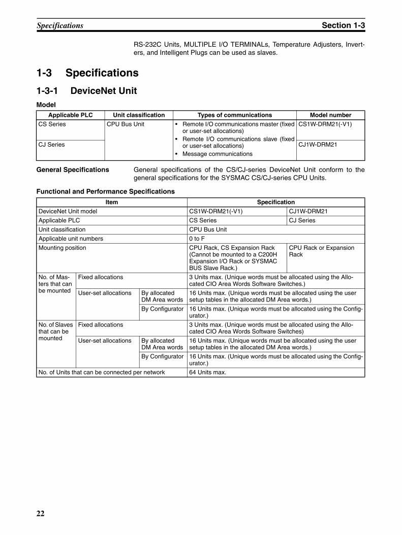
1-3-1 DeviceNet UnitModel
General Specifications General specifications of the CS/CJ-series DeviceNet Unit conform to thegeneral specifications for the SYSMAC CS/CJ-series CPU Units.
Functional and Performance Specifications
Applicable PLC Unit classification Types of communications Model number
CS Series CPU Bus Unit • Remote I/O communications master (fixedor user-set allocations)
• Remote I/O communications slave (fixedor user-set allocations)
• Message communications
CS1W-DRM21(-V1)
CJ Series CJ1W-DRM21
Item Specification
DeviceNet Unit model CS1W-DRM21(-V1) CJ1W-DRM21
Applicable PLC CS Series CJ Series
Unit classification CPU Bus Unit
Applicable unit numbers 0 to F
Mounting position CPU Rack, CS Expansion Rack (Cannot be mounted to a C200H Expansion I/O Rack or SYSMAC BUS Slave Rack.)
CPU Rack or Expansion Rack
No. of Mas-ters that can be mounted
Fixed allocations 3 Units max. (Unique words must be allocated using the Allo-cated CIO Area Words Software Switches.)
User-set allocations By allocated DM Area words
16 Units max. (Unique words must be allocated using the user setup tables in the allocated DM Area words.)
By Configurator 16 Units max. (Unique words must be allocated using the Config-urator.)
No. of Slaves that can be mounted
Fixed allocations 3 Units max. (Unique words must be allocated using the Allo-cated CIO Area Words Software Switches)
User-set allocations By allocated DM Area words
16 Units max. (Unique words must be allocated using the user setup tables in the allocated DM Area words.)
By Configurator 16 Units max. (Unique words must be allocated using the Config-urator.)
No. of Units that can be connected per network 64 Units max.
22
Specifications Section 1-3
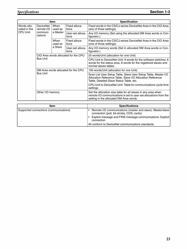
Words allo-cated in the CPU Unit
DeviceNet remote I/O communi-cations
When used as a Master
Fixed alloca-tions
Fixed words in the CS/CJ-series DeviceNet Area in the CIO Area (any of three settings).
User-set alloca-tions
Any I/O memory (Set using the allocated DM Area words or Con-figurator.)
When used as a Slave
Fixed alloca-tions
Fixed words in the CS/CJ-series DeviceNet Area in the CIO Area (one of three settings).
User-set alloca-tions
Any I/O memory words (Set in allocated DM Area words or Con-figurator.)
CIO Area words allocated for the CPU Bus Unit
25 words/Unit (allocation for one Unit)
CPU Unit to DeviceNet Unit: 9 words for the software switches, 6 words for the status area, 8 words for the registered slaves and normal slaves tables
DM Area words allocated for the CPU Bus Unit
100 words/Unit (allocation for one Unit)
Scan List User Setup Table, Slave User Setup Table, Master I/O Allocation Reference Table, Slave I/O Allocation Reference Table, Detailed Slave Status Table, etc.
CPU Unit to DeviceNet Unit: Table for communications cycle time settings
Other I/O memory Set the allocation size table for all slaves in any area when remote I/O communications is set to user-set allocations from the setting in the allocated DM Area words.
Item Specifications
Supported connections (communications) • Remote I/O communications (master and slave): Master/slaveconnection (poll, bit-strobe, COS, cyclic)
• Explicit message and FINS message communications: Explicitconnection
All conform to DeviceNet communications standards.
Item Specification
23
Specifications Section 1-3
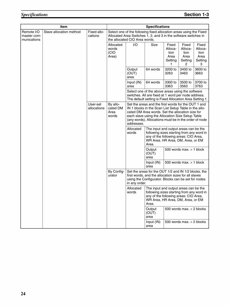
Remote I/O master com-munications
Slave allocation method Fixed allo-cations
Select one of the following fixed allocation areas using the Fixed Allocated Area Switches 1, 2, and 3 in the software switches in the allocated CIO Area words.
Allocated words (CIO Area)
I/O Size Fixed Alloca-
tion Area
Setting 1
Fixed Alloca-
tion Area
Setting 2
Fixed Alloca-
tion Area
Setting 3
Output (OUT) area
64 words 3200 to 3263
3400 to 3463
3600 to 3663
Input (IN) area
64 words 3300 to 3363
3500 to 3563
3700 to 3763
Select one of the above areas using the software switches. All are fixed at 1 word per node address. The default setting is Fixed Allocation Area Setting 1.
User-set allocations
By allo-cated DM Area words
Set the areas and the first words for the OUT 1 and IN 1 blocks in the Scan List Setup Table in the allo-cated DM Area words. Set the allocation size for each slave using the Allocation Size Setup Table (any words). Allocations must be in the order of node addresses.
Allocated words
The input and output areas can be the following sizes starting from any word in any of the following areas: CIO Area, WR Area, HR Area, DM, Area, or EM Area.
Output (OUT) area
500 words max. × 1 block
Input (IN) area
500 words max. × 1 block
By Config-urator
Set the areas for the OUT 1/2 and IN 1/2 blocks, the first words, and the allocation sizes for all slaves using the Configurator. Blocks can be set for nodes in any order.
Allocated words
The input and output areas can be the following sizes starting from any word in any of the following areas: CIO Area, WR Area, HR Area, DM, Area, or EM Area.
Output (OUT) area
500 words max. × 2 blocks
Input (IN) area
500 words max. × 2 blocks
Item Specifications
24
Specifications Section 1-3
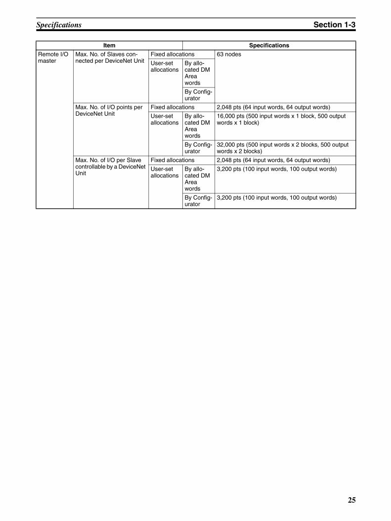
Remote I/O master
Max. No. of Slaves con-nected per DeviceNet Unit
Fixed allocations 63 nodes
User-set allocations
By allo-cated DM Area words
By Config-urator
Max. No. of I/O points per DeviceNet Unit
Fixed allocations 2,048 pts (64 input words, 64 output words)
User-set allocations
By allo-cated DM Area words
16,000 pts (500 input words x 1 block, 500 output words x 1 block)
By Config-urator
32,000 pts (500 input words x 2 blocks, 500 output words x 2 blocks)
Max. No. of I/O per Slave controllable by a DeviceNet Unit
Fixed allocations 2,048 pts (64 input words, 64 output words)
User-set allocations
By allo-cated DM Area words
3,200 pts (100 input words, 100 output words)
By Config-urator
3,200 pts (100 input words, 100 output words)
Item Specifications
25

Specifications Section 1-3
Remote I/O slave
Allocation method Fixed allo-cations
Select one of the following fixed allocation areas using the Slave Fixed Allocated Area Switches 1, 2, and 3 in the software switches in the allocated CIO Area words.
Allocated words (CIO Area)
I/O Size Fixed Alloca-
tion Area
Setting 1
Fixed Alloca-
tion Area
Setting 2
Fixed Alloca-
tion Area
Setting 3
Output (OUT) area to the slave from the master
1 word 3370 3570 3770
Input (OUT) area to the master from the slave
1 word 3270 3470 3670
Note Select one of the preceding areas using the software switches. All are fixed at 1 word per node address. The default setting is Fixed Allocation Area Setting 1.
User-set allocations
By allo-cated DM Area words
Set the areas, the first words, and slave allocation size for the OUT 1 and IN 1 blocks (total of 2 blocks) using the Slave User Allocation Setup Table in the allocated DM Area words.
Allocated words
The input and output areas can be the following sizes starting from any word in any of the following areas: CIO Area, WR Area, HR Area, DM, Area, or EM Area.
Output (OUT) area from this slave
100 words
Input (IN) area to this slave 100 words
By Config-urator
Set the areas for the OUT 1/2 and IN 1/2 blocks, the first words, and the slave allocation sizes using the Configurator.
Allocated words
The input and output areas can be the following sizes starting from any word in any of the following areas: CIO Area, WR Area, HR Area, DM, Area, or EM Area.
Output (OUT) area from this slave
100 words
Input (IN) area to this slave 100 words
Max. No. of I/O points per DeviceNet Unit slave
Fixed allocations 32 points (1 input word, 1 output word)
User-set allocations
By allo-cated DM Area words
3,200 pts (100 input words, 100 output words)
By Config-urator
4,800 pts (100 input words x 2, 100 output words x 1)
Item Specifications
26
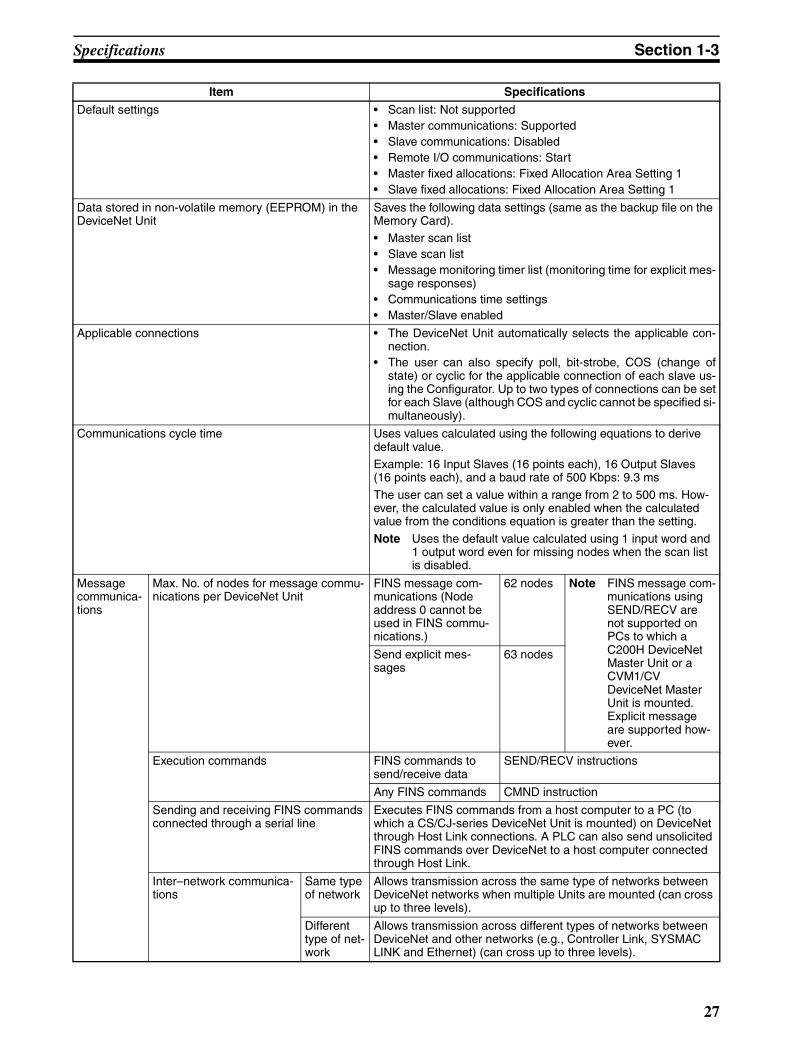
Specifications Section 1-3
Default settings • Scan list: Not supported • Master communications: Supported• Slave communications: Disabled• Remote I/O communications: Start• Master fixed allocations: Fixed Allocation Area Setting 1• Slave fixed allocations: Fixed Allocation Area Setting 1
Data stored in non-volatile memory (EEPROM) in the DeviceNet Unit
Saves the following data settings (same as the backup file on the Memory Card).• Master scan list• Slave scan list• Message monitoring timer list (monitoring time for explicit mes-
sage responses)• Communications time settings• Master/Slave enabled
Applicable connections • The DeviceNet Unit automatically selects the applicable con-nection.
• The user can also specify poll, bit-strobe, COS (change ofstate) or cyclic for the applicable connection of each slave us-ing the Configurator. Up to two types of connections can be setfor each Slave (although COS and cyclic cannot be specified si-multaneously).
Communications cycle time Uses values calculated using the following equations to derive default value.Example: 16 Input Slaves (16 points each), 16 Output Slaves (16 points each), and a baud rate of 500 Kbps: 9.3 ms
The user can set a value within a range from 2 to 500 ms. How-ever, the calculated value is only enabled when the calculated value from the conditions equation is greater than the setting.
Note Uses the default value calculated using 1 input word and 1 output word even for missing nodes when the scan list is disabled.
Message communica-tions
Max. No. of nodes for message commu-nications per DeviceNet Unit
FINS message com-munications (Node address 0 cannot be used in FINS commu-nications.)
62 nodes Note FINS message com-munications using SEND/RECV are not supported on PCs to which a C200H DeviceNet Master Unit or a CVM1/CV DeviceNet Master Unit is mounted. Explicit message are supported how-ever.
Send explicit mes-sages
63 nodes
Execution commands FINS commands to send/receive data
SEND/RECV instructions
Any FINS commands CMND instruction
Sending and receiving FINS commands connected through a serial line
Executes FINS commands from a host computer to a PC (to which a CS/CJ-series DeviceNet Unit is mounted) on DeviceNet through Host Link connections. A PLC can also send unsolicited FINS commands over DeviceNet to a host computer connected through Host Link.
Inter–network communica-tions
Same type of network
Allows transmission across the same type of networks between DeviceNet networks when multiple Units are mounted (can cross up to three levels).
Different type of net-work
Allows transmission across different types of networks between DeviceNet and other networks (e.g., Controller Link, SYSMAC LINK and Ethernet) (can cross up to three levels).
Item Specifications
27
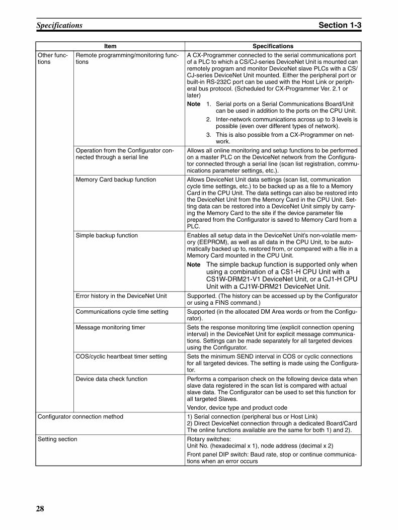
Specifications Section 1-3
Other func-tions
Remote programming/monitoring func-tions
A CX-Programmer connected to the serial communications port of a PLC to which a CS/CJ-series DeviceNet Unit is mounted can remotely program and monitor DeviceNet slave PLCs with a CS/CJ-series DeviceNet Unit mounted. Either the peripheral port or built-in RS-232C port can be used with the Host Link or periph-eral bus protocol. (Scheduled for CX-Programmer Ver. 2.1 or later)Note 1. Serial ports on a Serial Communications Board/Unit
can be used in addition to the ports on the CPU Unit.2. Inter-network communications across up to 3 levels is
possible (even over different types of network).
3. This is also possible from a CX-Programmer on net-work.
Operation from the Configurator con-nected through a serial line
Allows all online monitoring and setup functions to be performed on a master PLC on the DeviceNet network from the Configura-tor connected through a serial line (scan list registration, commu-nications parameter settings, etc.).
Memory Card backup function Allows DeviceNet Unit data settings (scan list, communication cycle time settings, etc.) to be backed up as a file to a Memory Card in the CPU Unit. The data settings can also be restored into the DeviceNet Unit from the Memory Card in the CPU Unit. Set-ting data can be restored into a DeviceNet Unit simply by carry-ing the Memory Card to the site if the device parameter file prepared from the Configurator is saved to Memory Card from a PLC.
Simple backup function Enables all setup data in the DeviceNet Unit’s non-volatile mem-ory (EEPROM), as well as all data in the CPU Unit, to be auto-matically backed up to, restored from, or compared with a file in a Memory Card mounted in the CPU Unit.
Note The simple backup function is supported only when using a combination of a CS1-H CPU Unit with a CS1W-DRM21-V1 DeviceNet Unit, or a CJ1-H CPU Unit with a CJ1W-DRM21 DeviceNet Unit.
Error history in the DeviceNet Unit Supported. (The history can be accessed up by the Configurator or using a FINS command.)
Communications cycle time setting Supported (in the allocated DM Area words or from the Configu-rator).
Message monitoring timer Sets the response monitoring time (explicit connection opening interval) in the DeviceNet Unit for explicit message communica-tions. Settings can be made separately for all targeted devices using the Configurator.
COS/cyclic heartbeat timer setting Sets the minimum SEND interval in COS or cyclic connections for all targeted devices. The setting is made using the Configura-tor.
Device data check function Performs a comparison check on the following device data when slave data registered in the scan list is compared with actual slave data. The Configurator can be used to set this function for all targeted Slaves. Vendor, device type and product code
Configurator connection method 1) Serial connection (peripheral bus or Host Link)2) Direct DeviceNet connection through a dedicated Board/CardThe online functions available are the same for both 1) and 2).
Setting section Rotary switches: Unit No. (hexadecimal x 1), node address (decimal x 2)Front panel DIP switch: Baud rate, stop or continue communica-tions when an error occurs
Item Specifications
28
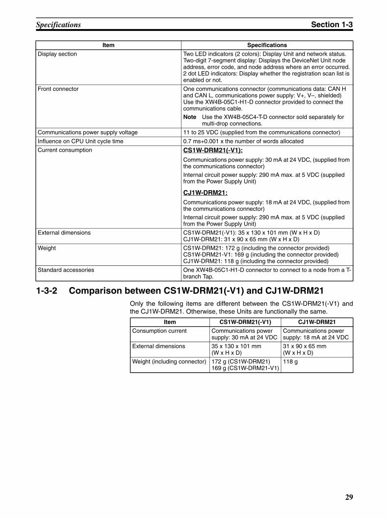
Specifications Section 1-3
1-3-2 Comparison between CS1W-DRM21(-V1) and CJ1W-DRM21Only the following items are different between the CS1W-DRM21(-V1) andthe CJ1W-DRM21. Otherwise, these Units are functionally the same.
Display section Two LED indicators (2 colors): Display Unit and network status. Two-digit 7-segment display: Displays the DeviceNet Unit node address, error code, and node address where an error occurred.2 dot LED indicators: Display whether the registration scan list is enabled or not.
Front connector One communications connector (communications data: CAN H and CAN L, communications power supply: V+, V–, shielded)Use the XW4B-05C1-H1-D connector provided to connect the communications cable.Note Use the XW4B-05C4-T-D connector sold separately for
multi-drop connections.
Communications power supply voltage 11 to 25 VDC (supplied from the communications connector)
Influence on CPU Unit cycle time 0.7 ms+0.001 x the number of words allocated
Current consumption CS1W-DRM21(-V1):Communications power supply: 30 mA at 24 VDC, (supplied from the communications connector)
Internal circuit power supply: 290 mA max. at 5 VDC (supplied from the Power Supply Unit)
CJ1W-DRM21:Communications power supply: 18 mA at 24 VDC, (supplied from the communications connector)Internal circuit power supply: 290 mA max. at 5 VDC (supplied from the Power Supply Unit)
External dimensions CS1W-DRM21(-V1): 35 x 130 x 101 mm (W x H x D)CJ1W-DRM21: 31 x 90 x 65 mm (W x H x D)
Weight CS1W-DRM21: 172 g (including the connector provided)CS1W-DRM21-V1: 169 g (including the connector provided)CJ1W-DRM21: 118 g (including the connector provided)
Standard accessories One XW4B-05C1-H1-D connector to connect to a node from a T-branch Tap.
Item Specifications
Item CS1W-DRM21(-V1) CJ1W-DRM21
Consumption current Communications power supply: 30 mA at 24 VDC
Communications power supply: 18 mA at 24 VDC
External dimensions 35 x 130 x 101 mm (W x H x D)
31 x 90 x 65 mm (W x H x D)
Weight (including connector) 172 g (CS1W-DRM21)169 g (CS1W-DRM21-V1)
118 g
29
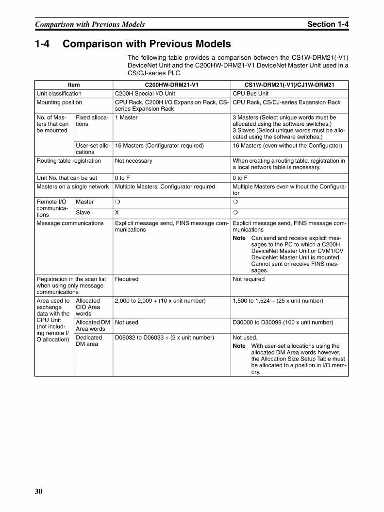
Comparison with Previous Models Section 1-4
1-4 Comparison with Previous ModelsThe following table provides a comparison between the CS1W-DRM21(-V1)DeviceNet Unit and the C200HW-DRM21-V1 DeviceNet Master Unit used in aCS/CJ-series PLC.
Item C200HW-DRM21-V1 CS1W-DRM21(-V1)/CJ1W-DRM21
Unit classification C200H Special I/O Unit CPU Bus Unit
Mounting position CPU Rack, C200H I/O Expansion Rack, CS-series Expansion Rack
CPU Rack, CS/CJ-series Expansion Rack
No. of Mas-ters that can be mounted
Fixed alloca-tions
1 Master 3 Masters (Select unique words must be allocated using the software switches.)3 Slaves (Select unique words must be allo-cated using the software switches.)
User-set allo-cations
16 Masters (Configurator required) 16 Masters (even without the Configurator)
Routing table registration Not necessary When creating a routing table, registration in a local network table is necessary.
Unit No. that can be set 0 to F 0 to F
Masters on a single network Multiple Masters, Configurator required Multiple Masters even without the Configura-tor
Remote I/O communica-tions
Master
Slave X
Message communications Explicit message send, FINS message com-munications
Explicit message send, FINS message com-munications
Note Can send and receive explicit mes-sages to the PC to which a C200H DeviceNet Master Unit or CVM1/CV DeviceNet Master Unit is mounted. Cannot sent or receive FINS mes-sages.
Registration in the scan list when using only message communications
Required Not required
Area used to exchange data with the CPU Unit (not includ-ing remote I/O allocation)
Allocated CIO Area words
2,000 to 2,009 + (10 x unit number) 1,500 to 1,524 + (25 x unit number)
Allocated DM Area words
Not used D30000 to D30099 (100 x unit number)
Dedicated DM area
D06032 to D06033 + (2 x unit number) Not used.Note With user-set allocations using the
allocated DM Area words however, the Allocation Size Setup Table must be allocated to a position in I/O mem-ory.
30
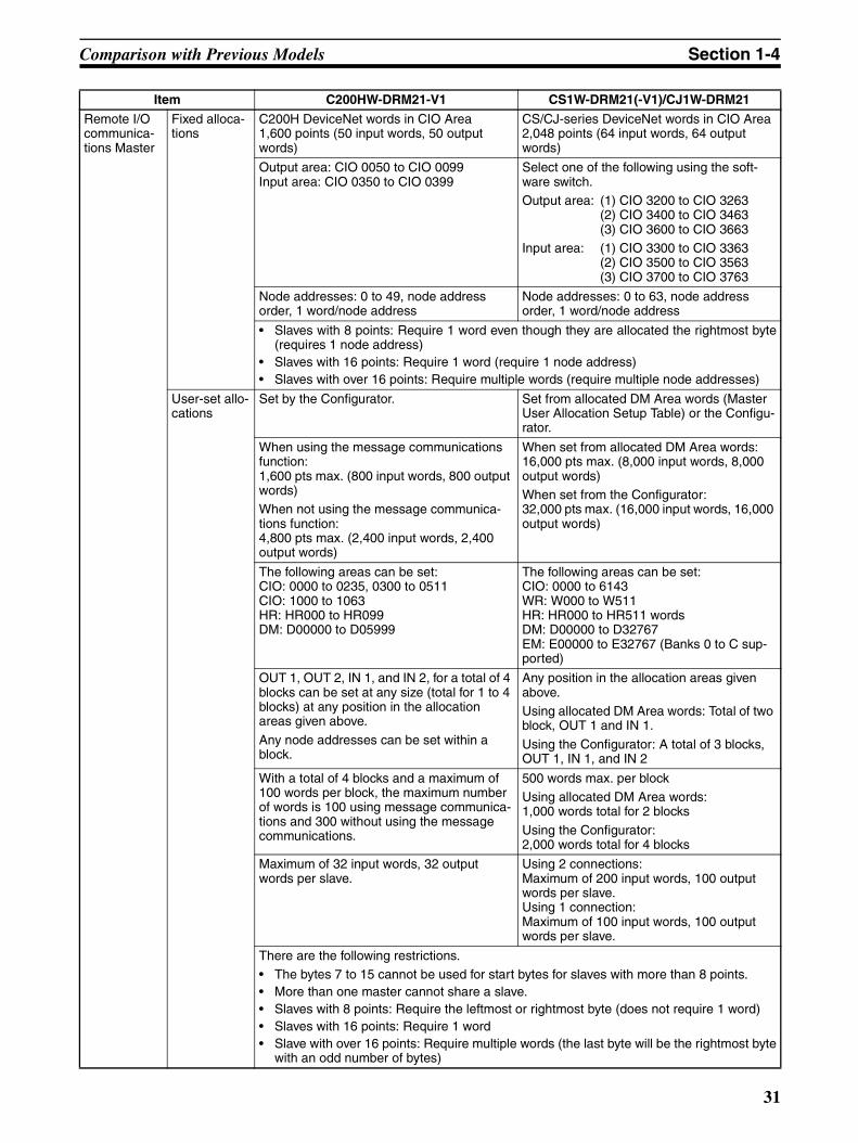
Comparison with Previous Models Section 1-4
Remote I/O communica-tions Master
Fixed alloca-tions
C200H DeviceNet words in CIO Area1,600 points (50 input words, 50 output words)
CS/CJ-series DeviceNet words in CIO Area2,048 points (64 input words, 64 output words)
Output area: CIO 0050 to CIO 0099 Input area: CIO 0350 to CIO 0399
Select one of the following using the soft-ware switch.Output area: (1) CIO 3200 to CIO 3263
(2) CIO 3400 to CIO 3463 (3) CIO 3600 to CIO 3663
Input area: (1) CIO 3300 to CIO 3363 (2) CIO 3500 to CIO 3563 (3) CIO 3700 to CIO 3763
Node addresses: 0 to 49, node address order, 1 word/node address
Node addresses: 0 to 63, node address order, 1 word/node address
• Slaves with 8 points: Require 1 word even though they are allocated the rightmost byte(requires 1 node address)
• Slaves with 16 points: Require 1 word (require 1 node address)• Slaves with over 16 points: Require multiple words (require multiple node addresses)
User-set allo-cations
Set by the Configurator. Set from allocated DM Area words (Master User Allocation Setup Table) or the Configu-rator.
When using the message communications function:1,600 pts max. (800 input words, 800 output words)When not using the message communica-tions function:4,800 pts max. (2,400 input words, 2,400 output words)
When set from allocated DM Area words:16,000 pts max. (8,000 input words, 8,000 output words)When set from the Configurator:32,000 pts max. (16,000 input words, 16,000 output words)
The following areas can be set:CIO: 0000 to 0235, 0300 to 0511 CIO: 1000 to 1063 HR: HR000 to HR099 DM: D00000 to D05999
The following areas can be set:CIO: 0000 to 6143 WR: W000 to W511 HR: HR000 to HR511 wordsDM: D00000 to D32767EM: E00000 to E32767 (Banks 0 to C sup-ported)
OUT 1, OUT 2, IN 1, and IN 2, for a total of 4 blocks can be set at any size (total for 1 to 4 blocks) at any position in the allocation areas given above.
Any node addresses can be set within a block.
Any position in the allocation areas given above.Using allocated DM Area words: Total of two block, OUT 1 and IN 1.
Using the Configurator: A total of 3 blocks, OUT 1, IN 1, and IN 2
With a total of 4 blocks and a maximum of 100 words per block, the maximum number of words is 100 using message communica-tions and 300 without using the message communications.
500 words max. per blockUsing allocated DM Area words:1,000 words total for 2 blocks
Using the Configurator:2,000 words total for 4 blocks
Maximum of 32 input words, 32 output words per slave.
Using 2 connections: Maximum of 200 input words, 100 output words per slave. Using 1 connection: Maximum of 100 input words, 100 output words per slave.
There are the following restrictions.• The bytes 7 to 15 cannot be used for start bytes for slaves with more than 8 points.• More than one master cannot share a slave.• Slaves with 8 points: Require the leftmost or rightmost byte (does not require 1 word)• Slaves with 16 points: Require 1 word• Slave with over 16 points: Require multiple words (the last byte will be the rightmost byte
with an odd number of bytes)
Item C200HW-DRM21-V1 CS1W-DRM21(-V1)/CJ1W-DRM21
31
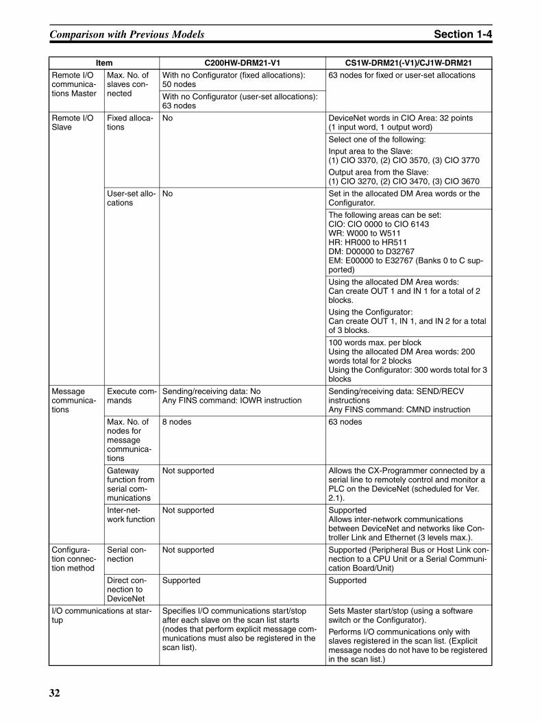
Comparison with Previous Models Section 1-4
Remote I/O communica-tions Master
Max. No. of slaves con-nected
With no Configurator (fixed allocations): 50 nodes
63 nodes for fixed or user-set allocations
With no Configurator (user-set allocations): 63 nodes
Remote I/O Slave
Fixed alloca-tions
No DeviceNet words in CIO Area: 32 points (1 input word, 1 output word)
Select one of the following:Input area to the Slave:(1) CIO 3370, (2) CIO 3570, (3) CIO 3770
Output area from the Slave:(1) CIO 3270, (2) CIO 3470, (3) CIO 3670
User-set allo-cations
No Set in the allocated DM Area words or the Configurator.
The following areas can be set:CIO: CIO 0000 to CIO 6143 WR: W000 to W511 HR: HR000 to HR511 DM: D00000 to D32767EM: E00000 to E32767 (Banks 0 to C sup-ported)
Using the allocated DM Area words:Can create OUT 1 and IN 1 for a total of 2 blocks.
Using the Configurator:Can create OUT 1, IN 1, and IN 2 for a total of 3 blocks.
100 words max. per blockUsing the allocated DM Area words: 200 words total for 2 blocksUsing the Configurator: 300 words total for 3 blocks
Message communica-tions
Execute com-mands
Sending/receiving data: NoAny FINS command: IOWR instruction
Sending/receiving data: SEND/RECV instructionsAny FINS command: CMND instruction
Max. No. of nodes for message communica-tions
8 nodes 63 nodes
Gateway function from serial com-munications
Not supported Allows the CX-Programmer connected by a serial line to remotely control and monitor a PLC on the DeviceNet (scheduled for Ver. 2.1).
Inter-net-work function
Not supported SupportedAllows inter-network communications between DeviceNet and networks like Con-troller Link and Ethernet (3 levels max.).
Configura-tion connec-tion method
Serial con-nection
Not supported Supported (Peripheral Bus or Host Link con-nection to a CPU Unit or a Serial Communi-cation Board/Unit)
Direct con-nection to DeviceNet
Supported Supported
I/O communications at star-tup
Specifies I/O communications start/stop after each slave on the scan list starts (nodes that perform explicit message com-munications must also be registered in the scan list).
Sets Master start/stop (using a software switch or the Configurator).Performs I/O communications only with slaves registered in the scan list. (Explicit message nodes do not have to be registered in the scan list.)
Item C200HW-DRM21-V1 CS1W-DRM21(-V1)/CJ1W-DRM21
32

Comparison with Previous Models Section 1-4
Starting and stopping remote communications during I/O communications
Starts or stops remote I/O communications using the Configurator or the software switch from a Programming Device.
Remote I/O communications with a communications error
Sets remote I/O communications start or stop when an error occurs in master communica-tions (set on DIP switch on the front of the Master).
Communications parameters Can be changed (communications cycle time).
Sending explicit messages to slaves made by another company
Supported
Master error history Yes (Can be read by the Configurator or FINS command.)
Setting communications cycle time
Supported (by the Configurator) Supported (with or without the Configurator)
Monitoring current communi-cations cycle time
Supported
Switch that disables commu-nications error stoppage
The switch that cancels communications error stoppage is different from the one that starts remote I/O communications.
The same software switch is used to cancel communications error stoppage and to start remote I/O communications.
Error with multiple Units mounted
A mounting error occurs with fixed alloca-tions.
An error does not occur even with multiple Units mounted. Operation will continue even if the same words are allocated to more than one Unit.
Error code on the front panel 7-seg-ment display
Error with multiple Units mounted
Display: E4 No check for multiple mounted Units.
PLC initializa-tion error
Display: F5 Used more detailed error codes in initializa-tion phase. Display: H@.
RAM error Display: F5 Changed to H3 (related to the above).
Incorrect switch setting
Display: F5 Changed to H5 (related to the above).
Routing table error
Display: E5 Changed to HC (related to the above).
PLC Unit WDT error
Display: All lit Display: E7 Unit does not reset. Explicit server functions run.
EEPROM error
Display: F8 Stops operation to store the scan list.
Display: E3 Operation continues for error history only (scan list stored in flash ROM)
Configura-tion data error (scan list SUM error)
Display: E8 Continues operation in DIS-ABLED mode.
Display: F7 Stops remote I/O communica-tions in Master communications.
Item C200HW-DRM21-V1 CS1W-DRM21(-V1)/CJ1W-DRM21
33
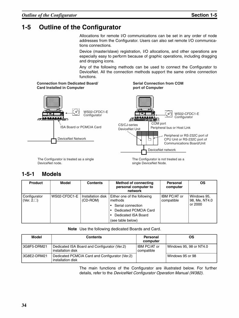
Outline of the Configurator Section 1-5
1-5 Outline of the ConfiguratorAllocations for remote I/O communications can be set in any order of nodeaddresses from the Configurator. Users can also set remote I/O communica-tions connections.
Device (master/slave) registration, I/O allocations, and other operations areespecially easy to perform because of graphic operations, including draggingand dropping icons.
Any of the following methods can be used to connect the Configurator toDeviceNet. All the connection methods support the same online connectionfunctions.
1-5-1 Models
Note Use the following dedicated Boards and Card.
The main functions of the Configurator are illustrated below. For furtherdetails, refer to the DeviceNet Configurator Operation Manual (W382).
Product Model Contents Method of connecting personal computer to
network
Personal computer
OS
Configurator (Ver. 2.@)
WS02-CFDC1-E Installation disk (CD-ROM)
Either one of the following methods• Serial connection• Dedicated PCMCIA Card• Dedicated ISA Board
(see table below)
IBM PC/AT or compatible
Windows 95, 98, Me, NT4.0 or 2000
Model Contents Personal computer
OS
3G8F5-DRM21 Dedicated ISA Board and Configurator (Ver.2) installation disk
IBM PC/AT or compatible
Windows 95, 98 or NT4.0
3G8E2-DRM21 Dedicated PCMCIA Card and Configurator (Ver.2) installation disk
Windows 95 or 98
Connection from Dedicated Board/Card Installed in Computer
Serial Connection from COM port of Computer
WS02-CFDC1-E Configurator
ISA Board or PCMCIA Card
DeviceNet Network
DeviceNet network
CS/CJ-seriesDeviceNet Unit Peripheral bus or Host Link
COM port
Peripheral or RS-232C port of CPU Unit or RS-232C port of Communications Board/Unit
WS02-CFDC1-E Configurator
The Configurator is treated as a single DeviceNet node.
The Configurator is not treated as a single DeviceNet Node.
34

Outline of the Configurator Section 1-5
Note 1. Master device parameters used in a scan list are created with either of thefollowing methods.
a) Using the Parameter Wizard
b) Setting all parameters
2. Connect only one Configurator to each Network.
3. Do not use the Configurator in a location with too much electromagneticnoise, particularly when using a PCMCIA Card. If noise is too extreme, thecomputer may run out-of-control, although there will be no negative effectson the DeviceNet network even if noise causes the computer to run out-of-control.
4. The only DeviceNet masters that can be handled by the Configurator areOMRON’s CS1W-DRM21(-V1), CJ1W-DRM21, CVM1-DRM21-V1, andC200HW-DRM21-V1.
1-5-2 Configurator Specifications
Main functions of Configurator
Setup functions
Remote I/O master allocations (with creation of a scan list) and remote I/O slave allocations
Enabling or disabling master or slave function of CS/CJ-seriesDeviceNet Unit.
Setting master device parameters except scan list parameters (i.e., connection settings, device data checks, and communications cycle time)
Setting other manufacturers' slave and master device parameters
Monitoring functions
Displaying a device information list
Monitoring master status, Unit status, Master error logs, and communications cycle data
Storage functionsSaving offline device information prepared with master device parameters or online network device information (Data is saved as network configuration files.)
Item Specification
Operating envi-ronment
Hardware Personal computer: IBM PC/AT or compatibleCPU: Pentium 166 MHz or higher (with Windows NT)Memory: 32 MbytesHard disk: A minimum of 15 Mbytes
OS Windows 95, 98, Me, NT4.0, or 2000
Network connection method Dedicated Board/Card 3G8F5-DRM21: Dedicated ISA Board3G8E2-DRM21: Dedicated PCMCIA Card
Serial connection (to DeviceNet network with gateway)
• Peripheral or RS-232C port of PLC with DeviceNetUnit mounted.
• RS-232C port of Serial Communications Board/Unit.Serial communications mode: Peripheral bus or Host Link
Dedicated Board/Card
Network status A single node address is used.
Connectable number of Boards/Cards
One/network
35

Outline of the Configurator Section 1-5
Main functions Setup functions Master device parameter settings for OMRON’s Master• Remote I/O master allocations (with a scan list)
The node address order can be set as desired. Two output blocks and two inputblocks can be allocated. (See note.)
• Remote I/O slave allocations• Setting master remote I/O communications connections• Setting slave remote I/O communications connections• Enabling or disabling device data checks through remote I/O communications
(checks on slave vendor ID, device type, and product code data)• Setting an explicit message monitor timer list• Setting a COS/cyclic heart beat timer value• Setting the communications cycle time
Note 1. A device Parameter Wizard is supported for the Master.2. Using remote I/O master allocations eliminate restrictions on node
addresses. Furthermore, a number of masters can be mounted to the PLC with no allocation area duplication.
Setting parameters for other manufacturers’ slaves (EDS file required).
Setting node addresses and baud rates
Monitoring func-tions
• Listing information on devices connected to the network (in node address order orremote I/O configuration order, for example)
• Monitoring Unit status data, Master function status data, and slave function statusdata
• Monitoring Master error historyCVM1-DRM21-V1 or C200HW-DRM21-V1: Up to 20 records of time, error code,and error condition dataCS1W-DRM21: Up to 64 records of time, error code, and error condition data
• Monitoring communication cycle time
Storage func-tions
Saving offline device information prepared with master device parameters or online network device information. Such data is saved as network configuration files.
Other functions • Reading/writing and preparing EDS files• Checking for duplicate I/O allocations in master parameters• Printing master/slave device parameters• Installing Expansion Modules to expand functions
Files that can be written • Master parameter files (parameters for OMRON Master: 1 file per node)Note Slave communications are saved as well in the master device parameters file
with the DeviceNet Unit.• Slave device parameter files (parameters for slaves: 1 file per node)• Network file (all master/slave parameters for masters/slaves in the device list: 1 file/
network)• EDS file (DeviceNet device definition file: 1 file/device type)
Item Specification
36
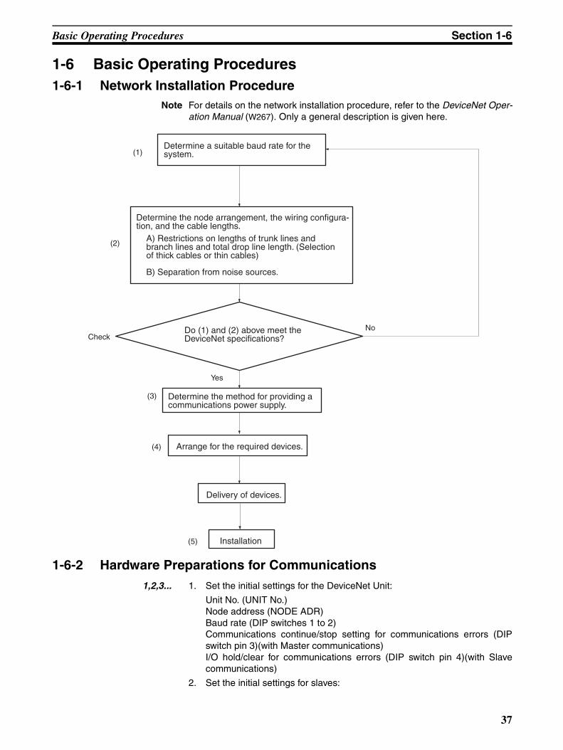
Basic Operating Procedures Section 1-6
1-6 Basic Operating Procedures1-6-1 Network Installation Procedure
Note For details on the network installation procedure, refer to the DeviceNet Oper-ation Manual (W267). Only a general description is given here.
1-6-2 Hardware Preparations for Communications1,2,3... 1. Set the initial settings for the DeviceNet Unit:
Unit No. (UNIT No.)Node address (NODE ADR)Baud rate (DIP switches 1 to 2)Communications continue/stop setting for communications errors (DIPswitch pin 3)(with Master communications)I/O hold/clear for communications errors (DIP switch pin 4)(with Slavecommunications)
2. Set the initial settings for slaves:
(1)
(2)
Check
Yes
(3)
(4)
(5)
No
Determine a suitable baud rate for the system.
Determine the node arrangement, the wiring configura-tion, and the cable lengths.
A) Restrictions on lengths of trunk lines and branch lines and total drop line length. (Selection of thick cables or thin cables)
B) Separation from noise sources.
Do (1) and (2) above meet the DeviceNet specifications?
Determine the method for providing a communications power supply.
Arrange for the required devices.
Delivery of devices.
Installation
37

Basic Operating Procedures Section 1-6
Node address (Pins 1 to 6)Baud rate (Pins 7 and 8)Etc.
3. Mount the Master and wire the network.
Treat as a CPU Bus Unit.Can mount to a CPU Rack or Expansion Rack.With fixed allocations: 3 Units max.With user-set allocations: 16 Units max.
4. Connect a Programming Device to the PLC and turn ON the power supplyto the PLC.
5. Generate the I/O tables.
Note 1. A slave may not go online if the communications power supply is turnedON after the slave is turned ON.
2. The communications power supply and slave power supply, the slave pow-er supply and PLC power supply, or all three of these power supplies maybe turned ON simultaneously.
1-6-3 Creating Routing TablesThe DeviceNet Unit functions as a Communications Unit in the same way as aSYSMAC LINK Unit, Controller Link Unit, and Ethernet Unit.
It is therefore necessary to create routing tables for the communications func-tions to be used, as shown in the table below.
Note 1. If a local network table already exists in the CPU unit being used, the De-viceNet Unit must be registered in that table.
2. The DeviceNet Unit must be registered in the local network table.
Refer to 6-3 Using FINS Message Communications for information on therouting tables.
The routing tables are created using CX-Net inside the CX-Programmer.Refer to the CX-Programmer Operation Manual (WS02-CXPC1-EV3) (W414) fordetails.
Note 1. A local network table is sometimes necessary even when the DeviceNetUnit is not operating across networks.
2. If you prepare a local network table inside the CPU Unit, be sure to registerthe DeviceNet Unit.
Mounted Units Using master or slave functions only
Using explicit message
communications (not supported
across networks)
Using FINS message
communications not across networks
Using FINS message communications across
networks
DeviceNet Unit is the only Communica-tions Unit mounted
Not necessary (See note 1.) Local network table (See note 2.) and relay network table are necessary.
Multiple DeviceNet Units mounted as Communications Units
Not necessary (See note 1.)
Local network table necessary (See note 2.)
DeviceNet Unit and other Communica-tions Unit mounted simultaneously
Local network table necessary (See note 2.)
38

Basic Operating Procedures Section 1-6
3. Even if a local network table exists inside the CPU Unit, the 7-segment dis-play of the DeviceNet Unit may indicate “HC” and FINS message/explicitmessage communications may not be possible unless the DeviceNet Unitis registered in the local network table.
1-6-4 Procedures Prior to Starting Communications
Using the Master FunctionTo use the master function, the Master Enable Switch (word n, bit 06) must beturned ON from a Programming Device. Enable master communicationsthrough CS1W-DRM21(-V1) properties if you are using a Configurator.
Note 1. Make sure the scan list is enabled when using the master function. Thiswill allow you to check whether slaves are online or not from the CPU Unitso that you will be able to determine whether or not the DeviceNet is com-municating properly.
2. Remote I/O communications with a specified slave can be turned OFF(disconnected) by turning ON (1) the corresponding Disconnect/ConnectSwitch (words n+6 to n+9) when a slave is replaced or is registered in thescan list prior to being connected. These switches are cleared when thepower supply is turned OFF, however, so a bit must be turned back ON (1)from the ladder program when the power turns ON for it to be valid again.
Fixed AllocationsUse the following procedure to use fixed allocations. Refer to 4-3 Fixed Alloca-tions for details on fixed allocations.
1,2,3... 1. Turn ON the communications, slave, and PLC power supplies.
Note Turn ON the communications power supply before turning ON theslave power supplies or the slaves may not go online.
2. Switch the CPU Unit to PROGRAM mode.
3. Check Unit Status 2 (word n+11, bit 03) from a Programming Device con-nected to the CPU Unit to see if the master function is ON (enabled). If itis enabled, skip step 4 below and proceed to step 5.
4. If the master function is OFF (disabled), turn ON the Master Enable Switch(word n, bit 06) from a Programming Device connected to the CPU Unit.
Note Execute this only when master communications are turned OFF. (Ifthe Master Enable Switch is turned ON when master communica-tions are ON, a Unit error will occur and a C2 error will be displayedon the 7-segment display on the front panel.)
5. Turn ON the Master Fixed Allocation Area Setting 1 to 3 Switches (word n,bits 8 to 10). Master remote I/O communications will begin with the scanlist disabled.
6. Turn ON the Scan List Enable Switch (word n, bit 00). Master remote I/Ocommunications will begin with the scan list enabled.
7. Switch the CPU Unit to RUN mode.
User-set Allocations Using Allocated DM Area WordsUse the following procedure to set allocations using the words allocated to theUnit in the DM Area. Refer to 4-4 User-set Allocations for details on user-setallocations.
1,2,3... 1. Turn ON the communications, slave, and PLC power supplies.
Note Turn ON the communications power supply before turning ON theslave power supplies or the slaves may not go online.
39
Basic Operating Procedures Section 1-6
2. Switch the CPU Unit to PROGRAM mode.
3. Check Unit Status 2 (word n+11, bit 03) from a Programming Device con-nected to the CPU Unit to see if the master function is ON (enabled). If itis enabled, skip step 4 below and proceed to step 5.
4. If the master function is OFF (disabled), turn ON the Master Enable Switch(word n, bit 06) from a Programming Device connected to the CPU Unit.
Note Execute this only when master communications are turned OFF. (Ifthe Master Enable Switch is turned ON when master communica-tions are enabled, a Unit error will occur and a C2 error will be dis-played on the 7-segment display on the front panel.)
5. Input data in advance into the Master User Allocation Setup Table (wordsm+1 to m+6) and the Allocation Size Setup Table (specify the position inwords m+5 and m+6)
6. Turn ON the Master User-set Allocation Switch (word n, bit 11). Master re-mote I/O communications will begin with the scan list enabled.
7. Switch the CPU Unit to RUN mode.
User-set Allocations Using the ConfiguratorUse the following procedure to set allocations using the Configurator. Refer toDeviceNet Configurator Operation Manual for details on Configurator operat-ing procedures
1,2,3... 1. Turn ON the communications, slave, and PLC power supplies.
Note Turn ON the communications power supply before turning ON theslave power supplies or the slaves may not go online.
2. Switch the CPU Unit to PROGRAM mode.
3. Create a network configuration file and device parameters file from theConfigurator. (Enable master communications in CS1W-DRM21(-V1)properties at this time.)
4. Download the above files to the devices on the network. Remote I/O com-munications will begin with the scan list enabled.
5. Switch the CPU Unit to RUN mode.
Using Slave FunctionTo use the slave function, the Slave Enable Switch (word n+1, bit 06) must beturned ON from a Programming Device. Enable slave communicationsthrough CS1W-DRM21(-V1)/CJ1W-DRM21 properties if you are using a Con-figurator.
With fixed allocations or allocations set in the allocated DM Area words, slavecommunications must be disabled prior to area allocation and must beenabled following area allocation. The order of the procedure is thus SlaveStop Switch (if slave communications are enabled), area allocation, and SlaveEnable Switch.
Note Slave communications must be disabled prior to area allocation when usingfixed allocations or allocations set in the allocated DM Area words, and thesettings must be read to the Unit when slave communications are enabled.Allocations will not be valid if slave communications are enabled during areaallocation.
Fixed AllocationsUse the following procedure to use fixed allocations. Refer to 5-2 Fixed Alloca-tions for details on fixed allocations.
40

Basic Operating Procedures Section 1-6
1,2,3... 1. Switch the CPU Unit to PROGRAM mode.
2. Check Unit Status 2 (word n+11, bit 07) from a Programming Device con-nected to the CPU Unit to see if the slave function is OFF (disabled). If it isdisabled, skip step 3 below and proceed to step 4.
3. If slave communications are enabled, turn ON the Slave Stop Switch (wordn+1, bit 07).
4. Turn ON the Slave Fixed Allocation Area Settings 1 to 3 Switches (wordn+1, bits 8 to 10).
5. Turn ON the Slave Enable Switch (word n+1, bit 06) from a ProgrammingDevice connected to the CPU Unit.
Note Execute this only when slave communications are turned OFF. (If theSlave Enable Switch is turned ON when slave communications areenabled, a Unit error will occur and a C2 error will be displayed onthe 7-segment display on the front panel.)
6. Switch the CPU Unit to RUN mode. Slave remote I/O communications willbegin.
User-set Allocations Using Allocated DM Area WordsUse the following procedure to set allocations using the words allocated to theUnit in the DM Area. Refer to 5-3 User-set Allocations for details on user-setallocations.
1,2,3... 1. Switch the CPU UNit to PROGRAM mode.
2. Check Unit Status 2 (word n+11, bit 07) from a Programming Device con-nected to the CPU Unit to see if the slave function is OFF (disabled). If it isdisabled, skip step 3 below and proceed to step 4.
3. If Slave is enabled, turn ON the Slave Stop Switch (word n+1, bit 07).
4. Input data in advance into the Slave User Allocation Setup Table (wordsm+8 to m+13).
5. Turn ON the user Slave User-set Allocation Switch (word n+1, bit 11).
6. Turn ON the Slave Enable Switch (word n+1, bit 06) from a ProgrammingDevice connected to the CPU Unit.
Note Execute this only when slave communications are turned OFF. (If theSlave Enable Switch is turned ON when slave communications areenabled, a Unit error will occur and a C2 error will be displayed onthe 7-segment display on the front panel.)
7. Switch the CPU Unit to RUN mode. Slave remote I/O communications willbegin.
User-set Allocations Using the ConfiguratorUse the following procedure to set allocations using the Configurator. Refer toDeviceNet Configurator Operation Manual for details on Configurator operat-ing procedures
1,2,3... 1. Switch the CPU Unit to PROGRAM mode.
2. Create a device parameter file from the Configurator. (Enable Slave com-munications in CS1W-DRM21(-V1) properties at this time.) Then down-load the file to the DeviceNet Unit.
3. Turn ON the Slave Enable Switch (word n+1, bit 06) from a ProgrammingDevice connected to the CPU Unit.
Note Execute this only when slave communications are turned OFF. (If theSlave Enable Switch is turned ON when slave communications are
41

Basic Operating Procedures Section 1-6
enabled, a Unit error will occur and a C2 error will be displayed onthe 7-segment display on the front panel.)
4. Switch the CPU Unit to RUN mode. Slave remote I/O communications willbegin.
Message Communications Only (Neither Master nor Slave Function Used)The DeviceNet Unit does not have to be registered in the scan list if it is onlyused for message communications. Message communications (send andreceive) can be executed with both master and slave communications dis-abled.
42
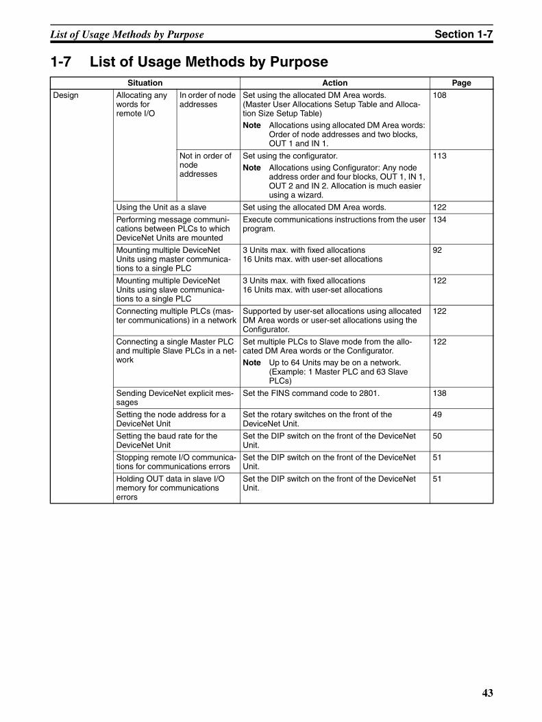
List of Usage Methods by Purpose Section 1-7
1-7 List of Usage Methods by PurposeSituation Action Page
Design Allocating any words for remote I/O
In order of node addresses
Set using the allocated DM Area words. (Master User Allocations Setup Table and Alloca-tion Size Setup Table)Note Allocations using allocated DM Area words:
Order of node addresses and two blocks, OUT 1 and IN 1.
108
Not in order of node addresses
Set using the configurator.Note Allocations using Configurator: Any node
address order and four blocks, OUT 1, IN 1, OUT 2 and IN 2. Allocation is much easier using a wizard.
113
Using the Unit as a slave Set using the allocated DM Area words. 122
Performing message communi-cations between PLCs to which DeviceNet Units are mounted
Execute communications instructions from the user program.
134
Mounting multiple DeviceNet Units using master communica-tions to a single PLC
3 Units max. with fixed allocations16 Units max. with user-set allocations
92
Mounting multiple DeviceNet Units using slave communica-tions to a single PLC
3 Units max. with fixed allocations16 Units max. with user-set allocations
122
Connecting multiple PLCs (mas-ter communications) in a network
Supported by user-set allocations using allocated DM Area words or user-set allocations using the Configurator.
122
Connecting a single Master PLC and multiple Slave PLCs in a net-work
Set multiple PLCs to Slave mode from the allo-cated DM Area words or the Configurator.Note Up to 64 Units may be on a network.
(Example: 1 Master PLC and 63 Slave PLCs)
122
Sending DeviceNet explicit mes-sages
Set the FINS command code to 2801. 138
Setting the node address for a DeviceNet Unit
Set the rotary switches on the front of the DeviceNet Unit.
49
Setting the baud rate for the DeviceNet Unit
Set the DIP switch on the front of the DeviceNet Unit.
50
Stopping remote I/O communica-tions for communications errors
Set the DIP switch on the front of the DeviceNet Unit.
51
Holding OUT data in slave I/O memory for communications errors
Set the DIP switch on the front of the DeviceNet Unit.
51
43
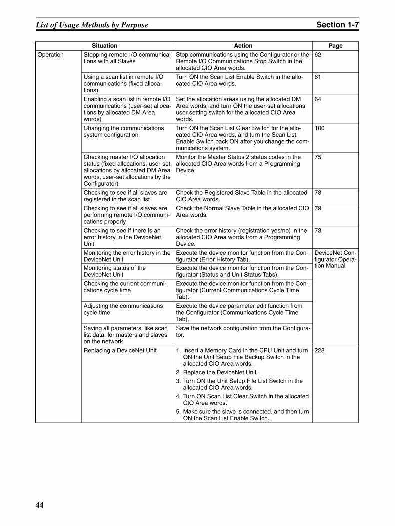
List of Usage Methods by Purpose Section 1-7
Operation Stopping remote I/O communica-tions with all Slaves
Stop communications using the Configurator or the Remote I/O Communications Stop Switch in the allocated CIO Area words.
62
Using a scan list in remote I/O communications (fixed alloca-tions)
Turn ON the Scan List Enable Switch in the allo-cated CIO Area words.
61
Enabling a scan list in remote I/O communications (user-set alloca-tions by allocated DM Area words)
Set the allocation areas using the allocated DM Area words, and turn ON the user-set allocations user setting switch for the allocated CIO Area words.
64
Changing the communications system configuration
Turn ON the Scan List Clear Switch for the allo-cated CIO Area words, and turn the Scan List Enable Switch back ON after you change the com-munications system.
100
Checking master I/O allocation status (fixed allocations, user-set allocations by allocated DM Area words, user-set allocations by the Configurator)
Monitor the Master Status 2 status codes in the allocated CIO Area words from a Programming Device.
75
Checking to see if all slaves are registered in the scan list
Check the Registered Slave Table in the allocated CIO Area words.
78
Checking to see if all slaves are performing remote I/O communi-cations properly
Check the Normal Slave Table in the allocated CIO Area words.
79
Checking to see if there is an error history in the DeviceNet Unit
Check the error history (registration yes/no) in the allocated CIO Area words from a Programming Device.
73
Monitoring the error history in the DeviceNet Unit
Execute the device monitor function from the Con-figurator (Error History Tab).
DeviceNet Con-figurator Opera-tion ManualMonitoring status of the
DeviceNet UnitExecute the device monitor function from the Con-figurator (Status and Unit Status Tabs).
Checking the current communi-cations cycle time
Execute the device monitor function from the Con-figurator (Current Communications Cycle Time Tab).
Adjusting the communications cycle time
Execute the device parameter edit function from the Configurator (Communications Cycle Time Tab).
Saving all parameters, like scan list data, for masters and slaves on the network
Save the network configuration from the Configura-tor.
Replacing a DeviceNet Unit 1. Insert a Memory Card in the CPU Unit and turn ON the Unit Setup File Backup Switch in the allocated CIO Area words.
2. Replace the DeviceNet Unit.3. Turn ON the Unit Setup File List Switch in the
allocated CIO Area words.
4. Turn ON Scan List Clear Switch in the allocated CIO Area words.
5. Make sure the slave is connected, and then turn ON the Scan List Enable Switch.
228
Situation Action Page
44
SECTION 2Nomenclature and Installation
This section describes the nomenclature and installation of the DeviceNet Unit.
2-1 Nomenclature and Functions . . . . . . . . . . . . . . . . . . . . . . . . . . . . . . . . . . . . . 46
2-1-1 Nomenclature and Functions . . . . . . . . . . . . . . . . . . . . . . . . . . . . . . 46
2-1-2 Status Indicators: MS and NS. . . . . . . . . . . . . . . . . . . . . . . . . . . . . . 47
2-1-3 Seven-Segment Display . . . . . . . . . . . . . . . . . . . . . . . . . . . . . . . . . . 48
2-1-4 Switch Settings . . . . . . . . . . . . . . . . . . . . . . . . . . . . . . . . . . . . . . . . . 49
2-2 Installing the DeviceNet Unit . . . . . . . . . . . . . . . . . . . . . . . . . . . . . . . . . . . . . 51
2-2-1 System Configuration Precautions . . . . . . . . . . . . . . . . . . . . . . . . . . 51
2-2-2 Mounting. . . . . . . . . . . . . . . . . . . . . . . . . . . . . . . . . . . . . . . . . . . . . . 52
2-2-3 Handling Precautions . . . . . . . . . . . . . . . . . . . . . . . . . . . . . . . . . . . . 53
2-2-4 External Dimensions. . . . . . . . . . . . . . . . . . . . . . . . . . . . . . . . . . . . . 55
45
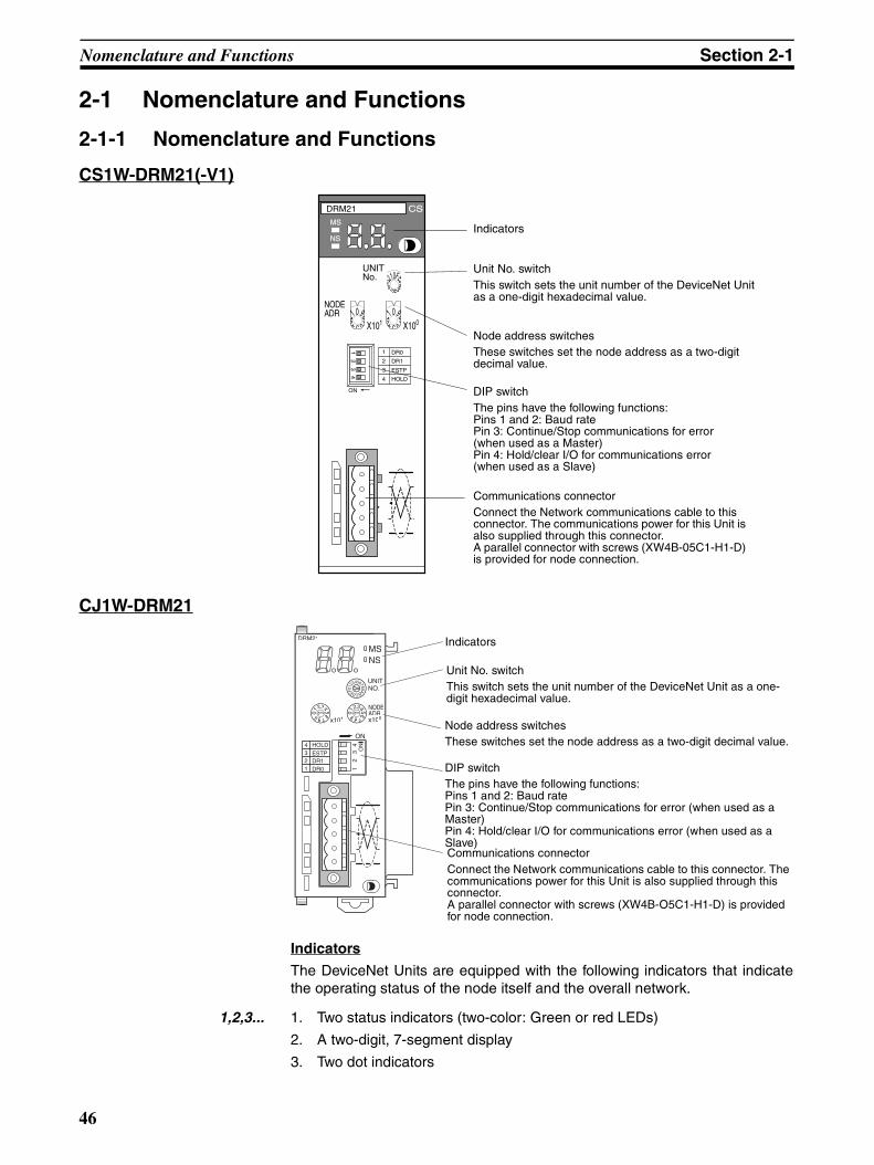
Nomenclature and Functions Section 2-1
2-1 Nomenclature and Functions
2-1-1 Nomenclature and Functions
CS1W-DRM21(-V1)
CJ1W-DRM21
Indicators
The DeviceNet Units are equipped with the following indicators that indicatethe operating status of the node itself and the overall network.
1,2,3... 1. Two status indicators (two-color: Green or red LEDs)
2. A two-digit, 7-segment display
3. Two dot indicators
UNITNo.
NODEADR
ON
DRM21 CS
MS
NS
4
3
2
1 DR0
DR1
ESTP
HOLD
X10198765432
10
X10098765432
10
FEDCBA9876543210
12
34
Indicators
Unit No. switchThis switch sets the unit number of the DeviceNet Unit as a one-digit hexadecimal value.
Node address switchesThese switches set the node address as a two-digit decimal value.
Communications connectorConnect the Network communications cable to this connector. The communications power for this Unit is also supplied through this connector.A parallel connector with screws (XW4B-05C1-H1-D) is provided for node connection.
DIP switchThe pins have the following functions:Pins 1 and 2: Baud ratePin 3: Continue/Stop communications for error (when used as a Master)Pin 4: Hold/clear I/O for communications error (when used as a Slave)
1 12
34
234 HOLD
ON
ESTPDR1DR0
DRM21
MSNS
6789
01
23456789
NODEADRx100x101
ON
Indicators
Unit No. switchThis switch sets the unit number of the DeviceNet Unit as a one-digit hexadecimal value.
Node address switches These switches set the node address as a two-digit decimal value.
DIP switchThe pins have the following functions:Pins 1 and 2: Baud ratePin 3: Continue/Stop communications for error (when used as a Master)Pin 4: Hold/clear I/O for communications error (when used as a Slave)Communications connectorConnect the Network communications cable to this connector. The communications power for this Unit is also supplied through this connector.A parallel connector with screws (XW4B-O5C1-H1-D) is provided for node connection.
46
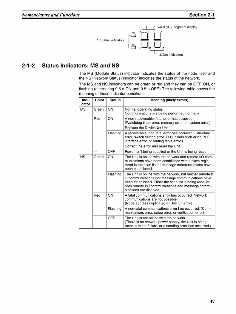
Nomenclature and Functions Section 2-1
2-1-2 Status Indicators: MS and NSThe MS (Module Status) indicator indicates the status of the node itself andthe NS (Network Status) indicator indicates the status of the network.
The MS and NS indicators can be green or red and they can be OFF, ON, orflashing (alternating 0.5-s ON and 0.5-s OFF.) The following table shows themeaning of these indicator conditions.
1. Status indicators
2. Two-digit, 7-segment display
3. Dot indicators
NS
MS
Indi-cator
Color Status Meaning (likely errors)
MS Green ON Normal operating statusCommunications are being performed normally.
Red ON A non-recoverable, fatal error has occurred.(Watchdog timer error, memory error, or system error.)
Replace the DeviceNet Unit.
Flashing A recoverable, non-fatal error has occurred. (Structure error, switch setting error, PLC initialization error, PLC interface error, or routing table error.)Correct the error and reset the Unit.
--- OFF Power isn’t being supplied or the Unit is being reset.
NS Green ON The Unit is online with the network and remote I/O com-munications have been established with a slave regis-tered in the scan list or message communications have been established.
Flashing The Unit is online with the network, but neither remote I/O communications nor message communications have been established. Either the scan list is being read, or both remote I/O communications and message commu-nications are disabled.
Red ON A fatal communications error has occurred. Network communications are not possible.(Node address duplicated or Bus Off error)
Flashing A non-fatal communications error has occurred. (Com-munications error, setup error, or verification error)
--- OFF The Unit is not online with the network.(There is no network power supply, the Unit is being reset, a minor failure, or a sending error has occurred.)
47
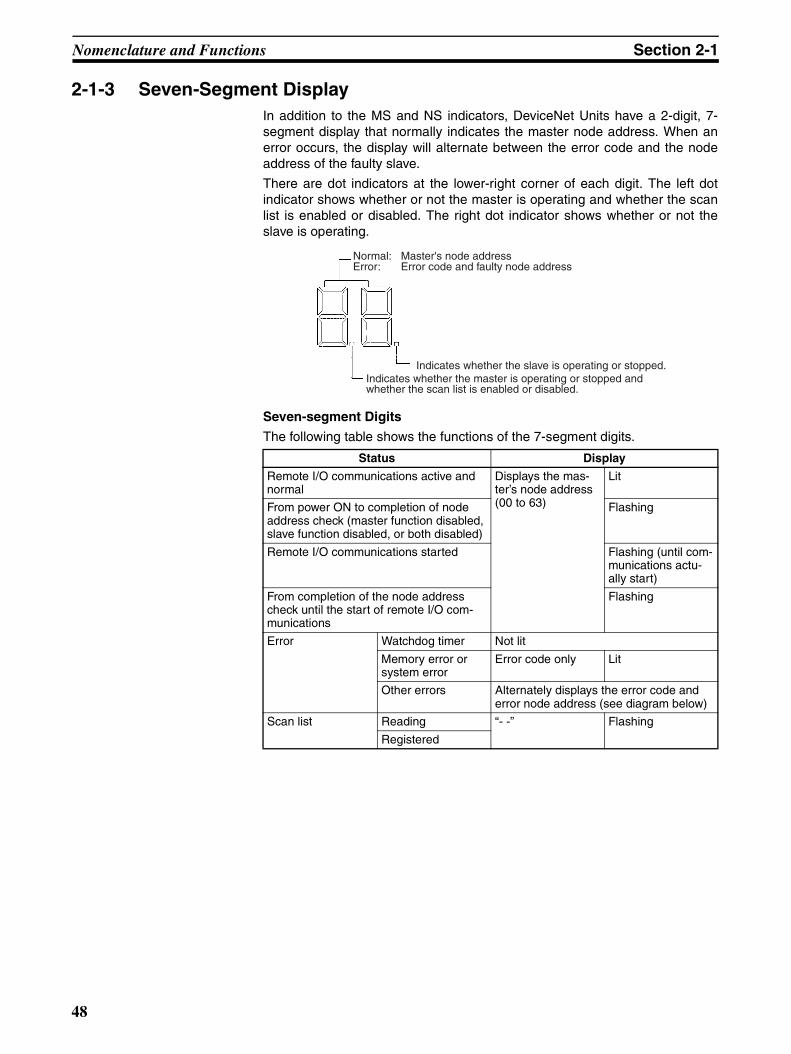
Nomenclature and Functions Section 2-1
2-1-3 Seven-Segment DisplayIn addition to the MS and NS indicators, DeviceNet Units have a 2-digit, 7-segment display that normally indicates the master node address. When anerror occurs, the display will alternate between the error code and the nodeaddress of the faulty slave.
There are dot indicators at the lower-right corner of each digit. The left dotindicator shows whether or not the master is operating and whether the scanlist is enabled or disabled. The right dot indicator shows whether or not theslave is operating.
Seven-segment Digits
The following table shows the functions of the 7-segment digits.
Status Display
Remote I/O communications active and normal
Displays the mas-ter’s node address (00 to 63)
Lit
From power ON to completion of node address check (master function disabled, slave function disabled, or both disabled)
Flashing
Remote I/O communications started Flashing (until com-munications actu-ally start)
From completion of the node address check until the start of remote I/O com-munications
Flashing
Error Watchdog timer Not lit
Memory error or system error
Error code only Lit
Other errors Alternately displays the error code and error node address (see diagram below)
Scan list Reading “- -” Flashing
Registered
Normal: Master's node addressError: Error code and faulty node address
Indicates whether the slave is operating or stopped.Indicates whether the master is operating or stopped and whether the scan list is enabled or disabled.
48

Nomenclature and Functions Section 2-1
The following diagram shows the alternating error code/ node address display.
The master’s error code and master’s node address will be displayed if anerror has occurred at the master.
There is no priority in the error codes; all errors that have occurred will be dis-played in order. All error codes begin with letters, so they can be distinguishedfrom node addresses immediately.
Dot Indicators
The following table shows the functions of the dot indicators.
2-1-4 Switch SettingsUnit No. Switch Use this switch to set the unit number of the DeviceNet Unit as a CPU Bus
Unit. The unit number setting determines the CIO and DM area words allo-cated to the Unit as software switches and the status area.
Setting method: One-digit hexadecimal
Setting range: 0 to F
Note 1. The unit number is set to 0 at the factory.
2. Any unit number from 0 to F can be set as long as it hasn’t been set onanother CPU Bus Unit connected to the same PLC.
3. Use a small flat-blade screwdriver to turn the rotary switches; be carefulnot to damage the switch.
4. Always turn OFF the PLC before changing the unit number setting.
5. If the unit number is the same as one set on another CPU Bus Unit con-nected to the same PLC, a duplicate number error will occur in the PLCand it won’t be possible to start up the DeviceNet network.
Node Address Switches Use these switches to set the node address of the Unit.
Setting method: Two-digit decimal
Setting range: 0 to 63
Error code (1 s)
Faulty slave's node address
(1 s)
OFF (0.1 s) OFF (0.3 s)Error code
(1 s)
OFF (0.1 s) OFF (0.3 s)
If there is an error at the DeviceNet Unit.
OFF (0.3 s) OFF (0.3 s)Master's node address (1 s)
Master's error code (1 s)
OFF (0.1 s)
Faulty slave's node address
(1 s)
Indicator Content Display
Left dot Scan list enabled/disabled, master function disabled
ON: Master function disabledFlashing: Scan list disabled modeOFF: Scan list enabled mode
Right dot Slave function dis-abled
ON: Slave function disabledOFF: Slave operating
FEDCBA9876543210 01
23456789ABCDEF
CS1W-DRM21(-V1) CJ1W-DRM21
X10198765432
10
X10098765432
10 012
3456789
012
3456789
X100X101
CS1W-DRM21(-V1) CJ1W-DRM21
49
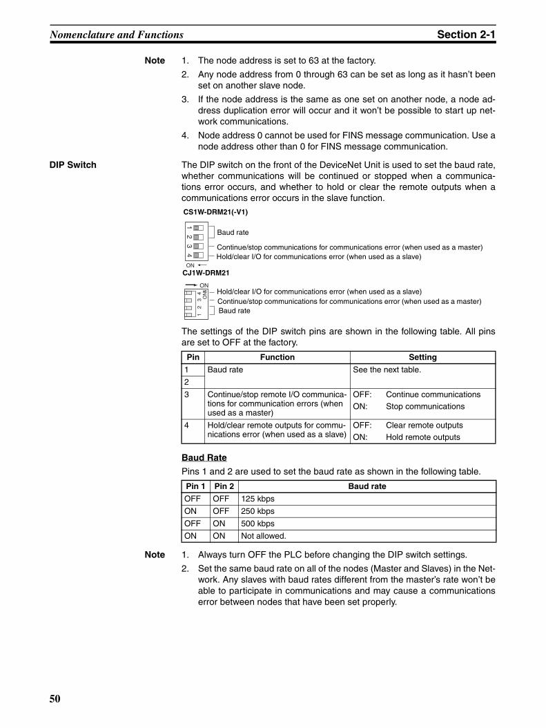
Nomenclature and Functions Section 2-1
Note 1. The node address is set to 63 at the factory.
2. Any node address from 0 through 63 can be set as long as it hasn’t beenset on another slave node.
3. If the node address is the same as one set on another node, a node ad-dress duplication error will occur and it won’t be possible to start up net-work communications.
4. Node address 0 cannot be used for FINS message communication. Use anode address other than 0 for FINS message communication.
DIP Switch The DIP switch on the front of the DeviceNet Unit is used to set the baud rate,whether communications will be continued or stopped when a communica-tions error occurs, and whether to hold or clear the remote outputs when acommunications error occurs in the slave function.
The settings of the DIP switch pins are shown in the following table. All pinsare set to OFF at the factory.
Baud Rate
Pins 1 and 2 are used to set the baud rate as shown in the following table.
Note 1. Always turn OFF the PLC before changing the DIP switch settings.
2. Set the same baud rate on all of the nodes (Master and Slaves) in the Net-work. Any slaves with baud rates different from the master’s rate won’t beable to participate in communications and may cause a communicationserror between nodes that have been set properly.
Pin Function Setting
1 Baud rate See the next table.
2
3 Continue/stop remote I/O communica-tions for communication errors (when used as a master)
OFF: Continue communicationsON: Stop communications
4 Hold/clear remote outputs for commu-nications error (when used as a slave)
OFF: Clear remote outputsON: Hold remote outputs
Pin 1 Pin 2 Baud rate
OFF OFF 125 kbps
ON OFF 250 kbps
OFF ON 500 kbps
ON ON Not allowed.
ON
12
34
12
34
ON
ON
CS1W-DRM21(-V1)
CJ1W-DRM21
Baud rateContinue/stop communications for communications error (when used as a master)Hold/clear I/O for communications error (when used as a slave)
Hold/clear I/O for communications error (when used as a slave)Continue/stop communications for communications error (when used as a master)
Baud rate
50

Installing the DeviceNet Unit Section 2-2
Continue/Stop Remote I/O Communications
When the DeviceNet Unit is used as a master, pin 3 is used to set whether ornot communications will stop after a communications error.
If pin 3 is ON, remote I/O communications will be stopped if one of the follow-ing errors occurs.
Remote I/O Communications Error Flag (n+12, bit 02 is ON)Send Timeout Flag (n+10, bit 08 is ON)Network Power Error Flag (n+10, bit 07 is ON)
Remote I/O communications will remain stopped even if the error is cleared.(Message communications and slave functions will continue.) To resume com-munications, turn ON the Remote I/O Communications Start Bit (word n, bit02) of Software Switches 1. Refer to 3-2 Allocated CIO Area Words for details.
Note The 7-segment display will show “A0” when remote I/O communications stop.Refer to SECTION 9 Troubleshooting and Maintenance.
If pin 3 is OFF, remote I/O communications will stop if a send timeout or net-work power error occurs, but will restart automatically when the cause of theerror is cleared.
Hold/Clear Remote Outputs
When the DeviceNet Unit is used as a slave, pin 4 is used to set whether tohold or clear remote outputs when a communications error occurs.
Note If the DeviceNet Unit is used as a slave, the 7-segment display will show “L9”when remote I/O communications stop. Refer to SECTION 9 Troubleshootingand Maintenance.
Communications Connectors
Color stickers that match communications cable colors are attached to thecommunications connectors. Match the colors when connecting communica-tions cables to the connectors. These colors are given in the following table
For details on communications specifications and wiring, refer to DeviceNet(CompoBus/D) Operation Manual (W267).
Note Before connecting communications cables, turn OFF the PLC power supply,all slave power supplies, and the communications power supply.
2-2 Installing the DeviceNet Unit
2-2-1 System Configuration Precautions• I/O words are allocated to CPU Bus Units according to the unit number
setting on the switch located on the front panel of the Unit, not accordingto Unit slot numbers. Refer to 3-1 Overview of Word Allocations.
Pin 3 Function
OFF Continue communications.
ON Stop communications.
Color Signal
Black Power line, negative voltage (V–)
Blue Communications line, low (CAN L)
--- Shield
White Communications line, high (CAN H)
Red Power line, positive voltage (V+)
51
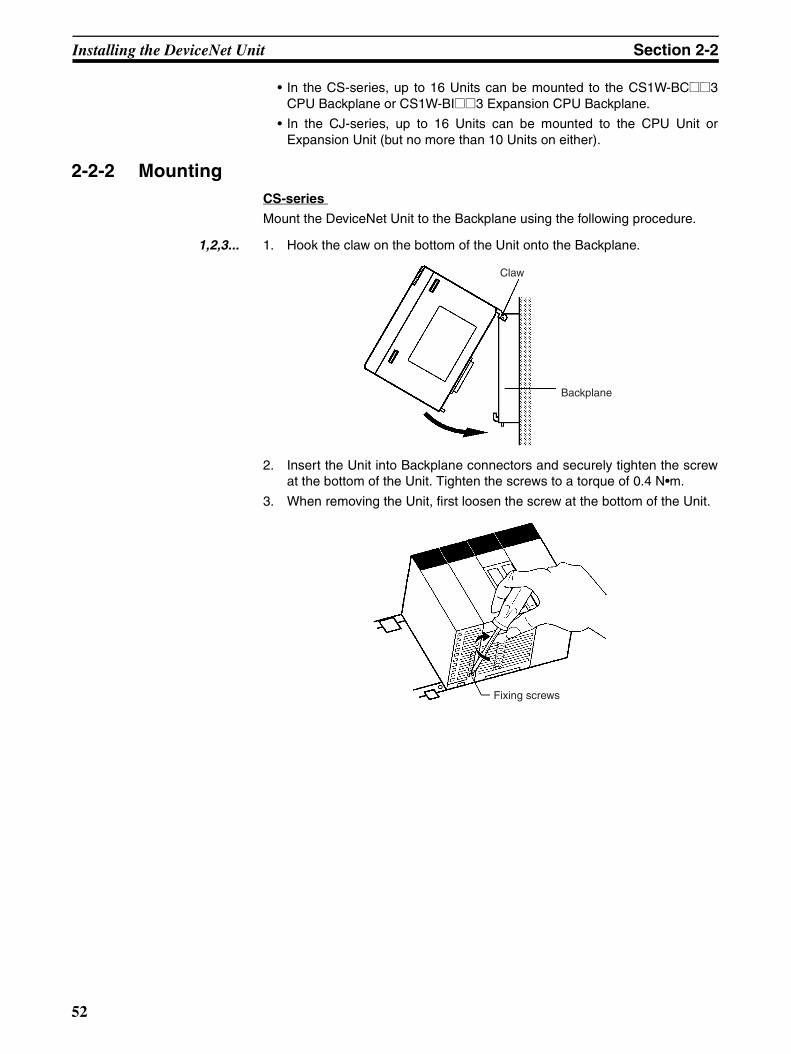
Installing the DeviceNet Unit Section 2-2
• In the CS-series, up to 16 Units can be mounted to the CS1W-BC@@3CPU Backplane or CS1W-BI@@3 Expansion CPU Backplane.
• In the CJ-series, up to 16 Units can be mounted to the CPU Unit orExpansion Unit (but no more than 10 Units on either).
2-2-2 MountingCS-series
Mount the DeviceNet Unit to the Backplane using the following procedure.
1,2,3... 1. Hook the claw on the bottom of the Unit onto the Backplane.
2. Insert the Unit into Backplane connectors and securely tighten the screwat the bottom of the Unit. Tighten the screws to a torque of 0.4 N•m.
3. When removing the Unit, first loosen the screw at the bottom of the Unit.
Claw
Backplane
Fixing screws
52
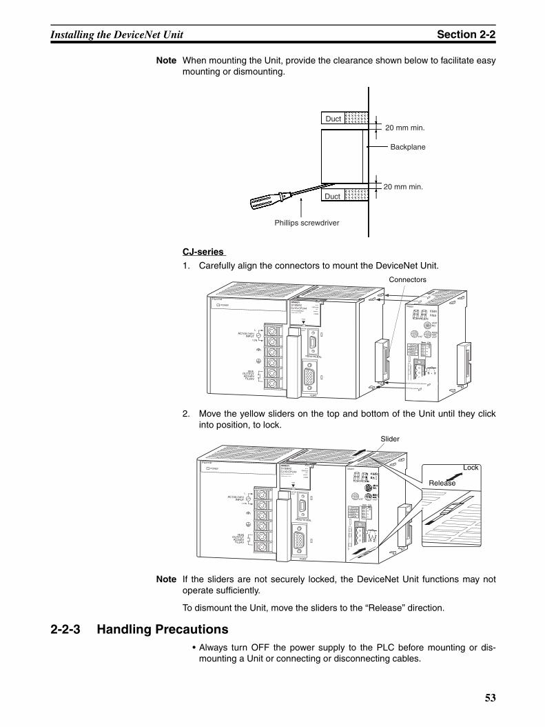
Installing the DeviceNet Unit Section 2-2
Note When mounting the Unit, provide the clearance shown below to facilitate easymounting or dismounting.
CJ-series
1. Carefully align the connectors to mount the DeviceNet Unit.
2. Move the yellow sliders on the top and bottom of the Unit until they clickinto position, to lock.
Note If the sliders are not securely locked, the DeviceNet Unit functions may notoperate sufficiently.
To dismount the Unit, move the sliders to the “Release” direction.
2-2-3 Handling Precautions• Always turn OFF the power supply to the PLC before mounting or dis-
mounting a Unit or connecting or disconnecting cables.
Duct20 mm min.
Backplane
Duct20 mm min.
Phillips screwdriver
PA205R
POWER
AC100-240V
L2/N
L1
DC24VAC240V
OUTPUTRUN
PERIPHERAL
RUN
INH
COMM
PRPHLCONTROLLER
PROGRAMMABLE
PORT
OPEN
4
DRM21
MSNS
Connectors
PA205R
POWER
AC100-240V
L2/N
L1
DC24V
OUTPUTRUN
PERIPHERAL
RUN
INH
COMM
PRPHLCONTROLLER
PROGRAMMABLE
PORT
OPEN
BUSY
4ON
DRM21
MS
ON
Slider
Lock
Release
53
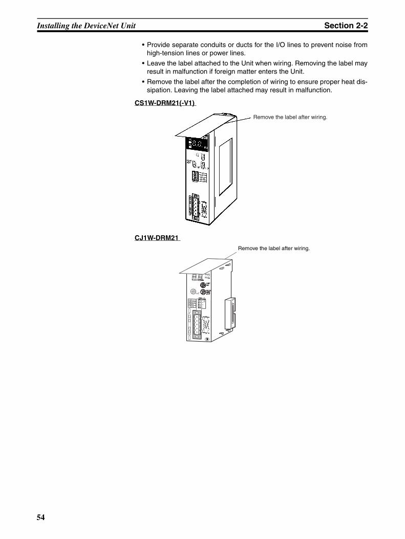
Installing the DeviceNet Unit Section 2-2
• Provide separate conduits or ducts for the I/O lines to prevent noise fromhigh-tension lines or power lines.
• Leave the label attached to the Unit when wiring. Removing the label mayresult in malfunction if foreign matter enters the Unit.
• Remove the label after the completion of wiring to ensure proper heat dis-sipation. Leaving the label attached may result in malfunction.
CS1W-DRM21(-V1)
CJ1W-DRM21
Remove the label after wiring.
1 12
34
234 HOLD
ESTPDR1DR0
MS
ON
Remove the label after wiring.
54

Installing the DeviceNet Unit Section 2-2
2-2-4 External DimensionsCS1W-DRM21(-V1)
These diagrams show the dimensions of the DeviceNet Unit. Refer to the CS1Series CPU Unit Operation Manual (W339) or the CJ Series CPU Unit Opera-tion Manual (W393) for the dimensions of the Unit when it is mounted to theBackplane. (All dimensions are in mm.)
CJ1W-DRM21
10135 13.7
1512 8
130
88
35
7
UNITNo.
NODEADR
ON
DRM21 CSCS
MSMS
NSNS
4
3
2
1 DR0
DR1
ESTP
HOLD
X10198765432
10
X10098765432
10
FEDCBA9876543210
12
34
31 13.7 65
90
50
35
5
1 12
34
234 HOLD
ON
ESTPDR1DR0
MSNS
NO.UNIT
01
ON
1511 5
55


SECTION 3Allocated CIO and DM Words
This section describes the words allocated to the DeviceNet Unit in the CIO Area and DM Area. These words both enablecontrolling the DeviceNet Unit and accessing Unit and network status.
3-1 Overview of Word Allocations . . . . . . . . . . . . . . . . . . . . . . . . . . . . . . . . . . . . 58
3-1-1 Allocated CIO Area Words. . . . . . . . . . . . . . . . . . . . . . . . . . . . . . . . 59
3-1-2 Allocated DM Area Words . . . . . . . . . . . . . . . . . . . . . . . . . . . . . . . . 59
3-2 Allocated CIO Area Words . . . . . . . . . . . . . . . . . . . . . . . . . . . . . . . . . . . . . . . 60
3-2-1 Software Switches 1 (Word n) . . . . . . . . . . . . . . . . . . . . . . . . . . . . . 60
3-2-2 Software Switches 2 (Word n+1) . . . . . . . . . . . . . . . . . . . . . . . . . . . 65
3-2-3 Master COS Send Switches (Words n+2 to n+5) . . . . . . . . . . . . . . . 69
3-2-4 Disconnect/Connect Switches (Words n+6 to n+9) . . . . . . . . . . . . . 69
3-2-5 Unit Status 1 (Word n+10) . . . . . . . . . . . . . . . . . . . . . . . . . . . . . . . . 71
3-2-6 Unit Status 2 (Word n+11) . . . . . . . . . . . . . . . . . . . . . . . . . . . . . . . . 72
3-2-7 Master Status 1 (Word n+12) . . . . . . . . . . . . . . . . . . . . . . . . . . . . . . 74
3-2-8 Master Status 2 (Word n+13) . . . . . . . . . . . . . . . . . . . . . . . . . . . . . . 75
3-2-9 Slave Status 1 (Word n+14) . . . . . . . . . . . . . . . . . . . . . . . . . . . . . . . 76
3-2-10 Slave Status 2 (Word n+15) . . . . . . . . . . . . . . . . . . . . . . . . . . . . . . . 78
3-2-11 Registered Slave Table (Words n+16 to n+19) . . . . . . . . . . . . . . . . . 78
3-2-12 Normal Slave Table (Words n+20 to n+23) . . . . . . . . . . . . . . . . . . . 79
3-2-13 C200H Master Replacement Master Status 1 (Word n+24) . . . . . . . 79
3-3 Allocated DM Area Words . . . . . . . . . . . . . . . . . . . . . . . . . . . . . . . . . . . . . . . 81
3-3-1 Communications Cycle Time Setup Table . . . . . . . . . . . . . . . . . . . . 81
3-3-2 Master User Allocations Setup Table . . . . . . . . . . . . . . . . . . . . . . . . 82
3-3-3 Allocation Size Setup Table . . . . . . . . . . . . . . . . . . . . . . . . . . . . . . . 84
3-3-4 Slave User Allocations Setup Table . . . . . . . . . . . . . . . . . . . . . . . . . 85
3-3-5 Communications Cycle Time Reference Table . . . . . . . . . . . . . . . . 87
3-3-6 Master User-set Allocations Reference Table . . . . . . . . . . . . . . . . . 87
3-3-7 Slave User-set Allocations Reference Table. . . . . . . . . . . . . . . . . . . 88
3-3-8 Slave Detailed Status . . . . . . . . . . . . . . . . . . . . . . . . . . . . . . . . . . . . 89
57

Overview of Word Allocations Section 3-1
3-1 Overview of Word AllocationsThe words shown in the following diagram are allocated according to the unitnumber setting. For each Unit, there are 25 words allocated in the CIO Areaand 100 words allocated in the DM Area.
First word allocated in the CIO Area: n = CIO 1,500 + (25 x unit number)
First word allocated in the DM Area: m = D30,000 + (100 x unit number)
Note The CPU Bus Unit Setup words are not used with a CS/CJ-series DeviceNetUnit.
CPU Bus Unit Unit number: 0CIO Area
Unit #0
Unit #1
Unit #15
Unit #0
Unit #1
Unit #15
CPU Bus UnitAllocated DM Area words
CPU Unit DeviceNet Unit
Local memory
Software switches
(I/O refresh) status
(I/O refresh) status
setup tablesLocal memory
CIO 1500CIO 1501
CIO 1524CIO 1525CIO 1526
CIO 1549
CIO 1875
CIO 1899
25 wds
25 wds
25 wds
25 wds
100 wds
100 wds
100 wds
100 wds
D30000D30001
D30099D30100D30101
D30199
D31500
D31599
58

Overview of Word Allocations Section 3-1
3-1-1 Allocated CIO Area WordsSoftware switches, DeviceNet Unit status, and error data are allocated in theCIO Area according to the unit number, as shown below. Software switchesare bits used as commands from the CPU Unit to the DeviceNet Unit toenable executing Unit functions.
3-1-2 Allocated DM Area WordsThe User Allocations Setup Tables and individual slave status by nodeaddress are allocated in the DM area.
Unit number Allocated words Unit number Allocated words
0 CIO 1500 to CIO 1524 8 CIO 1700 to CIO 1724
1 CIO 1525 to CIO 1549 9 CIO 1725 to CIO 1749
2 CIO 1550 to CIO 1574 10 CIO 1750 to CIO 1774
3 CIO 1575 to CIO 1599 11 CIO 1775 to CIO 1799
4 CIO 1600 to CIO 1624 12 CIO 1800 to CIO 1824
5 CIO 1625 to CIO 1649 13 CIO 1825 to CIO 1849
6 CIO 1650 to CIO 1674 14 CIO 1850 to CIO 1874
7 CIO 1675 to CIO 1699 15 CIO 1875 to CIO 1899
Unit number Allocated words Unit number Allocated words
0 D30000 to D30099 8 D30800 to D30899
1 D30100 to D30199 9 D30900 to D30999
2 D30200 to D30299 10 D31000 to D31099
3 D30300 to D30399 11 D31100 to D31199
4 D30400 to D30499 12 D31200 to D31299
5 D30500 to D30599 13 D31300 to D31399
6 D30600 to D30699 14 D31400 to D31499
7 D30700 to D30799 15 D31500 to D31599
59
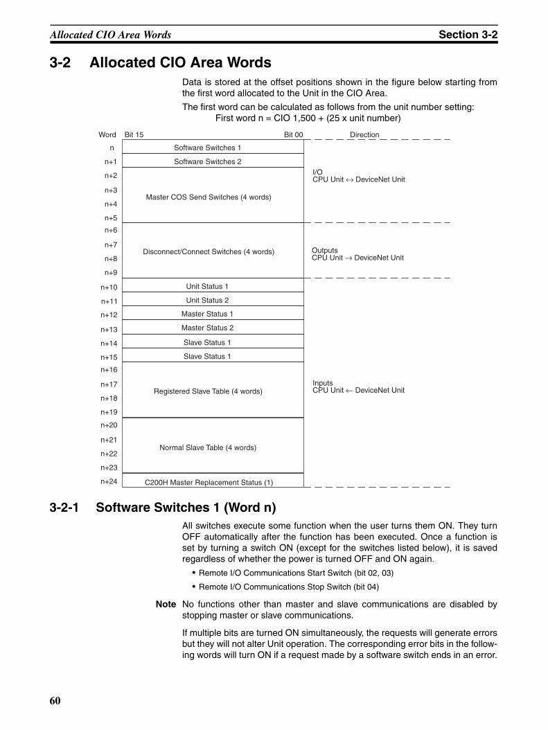
Allocated CIO Area Words Section 3-2
3-2 Allocated CIO Area WordsData is stored at the offset positions shown in the figure below starting fromthe first word allocated to the Unit in the CIO Area.
The first word can be calculated as follows from the unit number setting:First word n = CIO 1,500 + (25 x unit number)
3-2-1 Software Switches 1 (Word n)All switches execute some function when the user turns them ON. They turnOFF automatically after the function has been executed. Once a function isset by turning a switch ON (except for the switches listed below), it is savedregardless of whether the power is turned OFF and ON again.
• Remote I/O Communications Start Switch (bit 02, 03)
• Remote I/O Communications Stop Switch (bit 04)
Note No functions other than master and slave communications are disabled bystopping master or slave communications.
If multiple bits are turned ON simultaneously, the requests will generate errorsbut they will not alter Unit operation. The corresponding error bits in the follow-ing words will turn ON if a request made by a software switch ends in an error.
Word Bit 15
Software Switches 1
Software Switches 2
Master COS Send Switches (4 words)
Disconnect/Connect Switches (4 words)
Unit Status 1
Unit Status 2
Master Status 1
Master Status 2
Slave Status 1
Slave Status 1
Registered Slave Table (4 words)
Normal Slave Table (4 words)
C200H Master Replacement Status (1)
Bit 00 Direction
I/OCPU Unit ↔ DeviceNet Unit
OutputsCPU Unit → DeviceNet Unit
InputsCPU Unit ← DeviceNet Unit
n
n+1
n+12
n+15
n+13
n+14
n+2
n+5
n+3
n+4
n+6
n+9
n+7
n+8
n+10
n+11
n+16
n+19
n+17
n+18
n+20
n+23
n+21
n+22
n+24
60
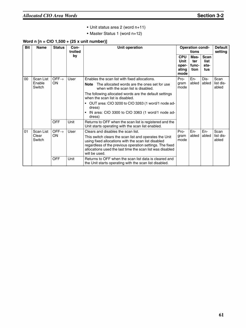
Allocated CIO Area Words Section 3-2
• Unit status area 2 (word n+11)
• Master Status 1 (word n+12)
Word n [n = CIO 1,500 + (25 x unit number)]Bit Name Status Con-
trolled by
Unit operation Operation condi-tions
Default setting
CPU Unit
oper-ating mode
Mas-ter
func-tion
Scan list sta-tus
00 Scan List Enable Switch
OFF→ON
User Enables the scan list with fixed allocations.Note The allocated words are the ones set for use
when with the scan list is disabled.
The following allocated words are the default settings when the scan list is disabled.• OUT area: CIO 3200 to CIO 3263 (1 word/1 node ad-
dress)• IN area: CIO 3300 to CIO 3363 (1 word/1 node ad-
dress)
Pro-gram mode
En-abled
Dis-abled
Scan list dis-abled
OFF Unit Returns to OFF when the scan list is registered and the Unit starts operating with the scan list enabled.
01 Scan List Clear Switch
OFF→ON
User Clears and disables the scan list.This switch clears the scan list and operates the Unit using fixed allocations with the scan list disabled regardless of the previous operation settings. The fixed allocations used the last time the scan list was disabled will be used.
Pro-gram mode
En-abled
En-abled
Scan list dis-abled
OFF Unit Returns to OFF when the scan list data is cleared and the Unit starts operating with the scan list disabled.
61
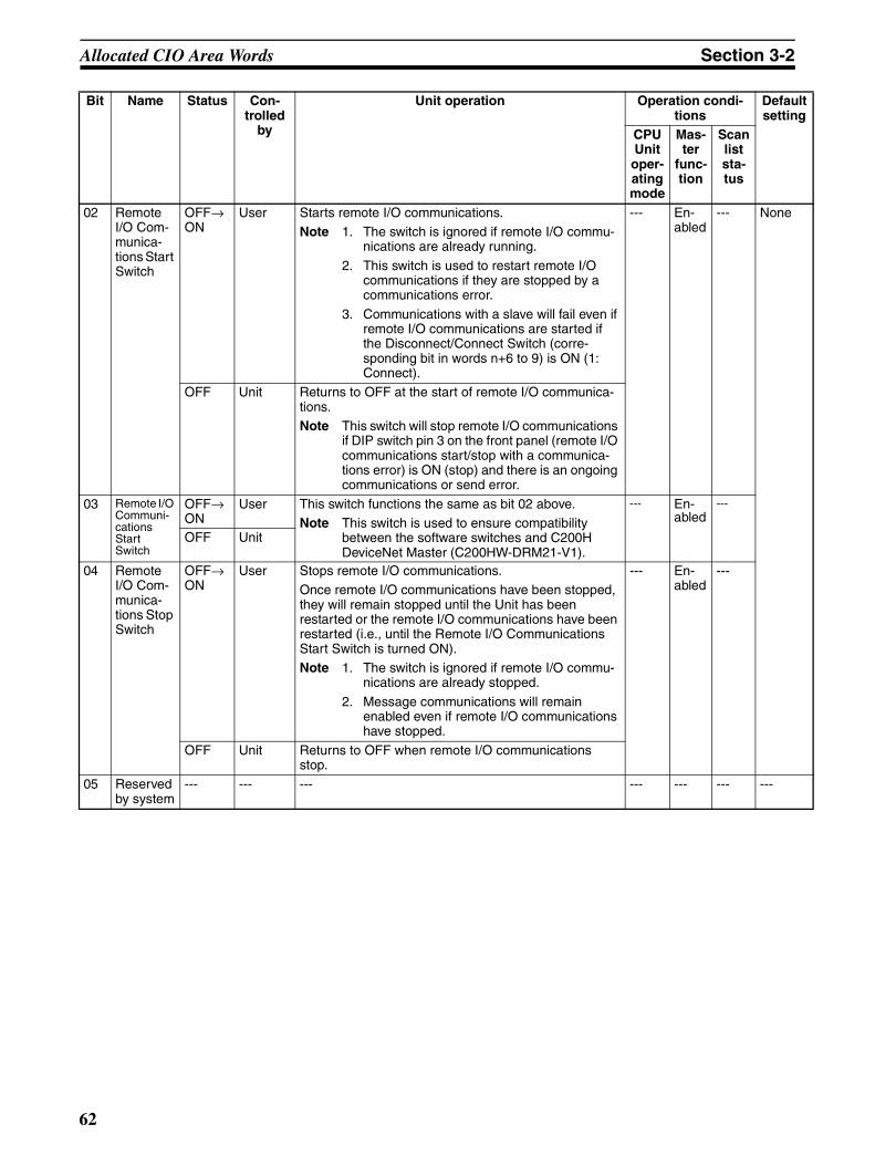
Allocated CIO Area Words Section 3-2
02 Remote I/O Com-munica-tions Start Switch
OFF→ON
User Starts remote I/O communications.Note 1. The switch is ignored if remote I/O commu-
nications are already running.
2. This switch is used to restart remote I/O communications if they are stopped by a communications error.
3. Communications with a slave will fail even if remote I/O communications are started if the Disconnect/Connect Switch (corre-sponding bit in words n+6 to 9) is ON (1: Connect).
--- En-abled
--- None
OFF Unit Returns to OFF at the start of remote I/O communica-tions.Note This switch will stop remote I/O communications
if DIP switch pin 3 on the front panel (remote I/O communications start/stop with a communica-tions error) is ON (stop) and there is an ongoing communications or send error.
03 Remote I/O Communi-cations Start Switch
OFF→ON
User This switch functions the same as bit 02 above.Note This switch is used to ensure compatibility
between the software switches and C200H DeviceNet Master (C200HW-DRM21-V1).
--- En-abled
---
OFF Unit
04 Remote I/O Com-munica-tions Stop Switch
OFF→ON
User Stops remote I/O communications.Once remote I/O communications have been stopped, they will remain stopped until the Unit has been restarted or the remote I/O communications have been restarted (i.e., until the Remote I/O Communications Start Switch is turned ON).Note 1. The switch is ignored if remote I/O commu-
nications are already stopped.
2. Message communications will remain enabled even if remote I/O communications have stopped.
--- En-abled
---
OFF Unit Returns to OFF when remote I/O communications stop.
05 Reserved by system
--- --- --- --- --- --- ---
Bit Name Status Con-trolled
by
Unit operation Operation condi-tions
Default setting
CPU Unit
oper-ating mode
Mas-ter
func-tion
Scan list sta-tus
62
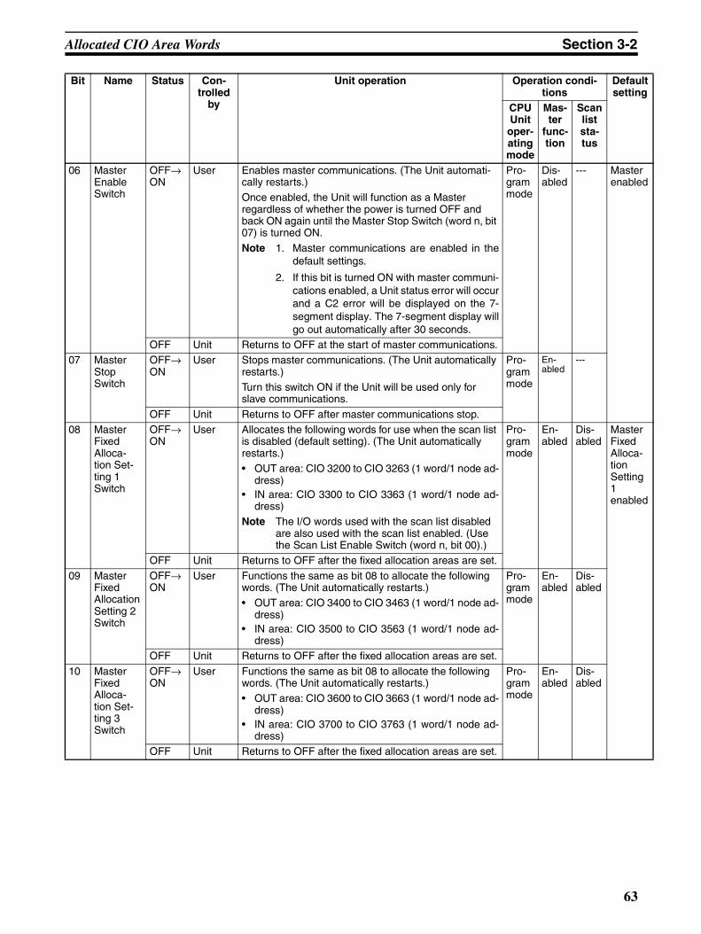
Allocated CIO Area Words Section 3-2
06 Master Enable Switch
OFF→ON
User Enables master communications. (The Unit automati-cally restarts.)Once enabled, the Unit will function as a Master regardless of whether the power is turned OFF and back ON again until the Master Stop Switch (word n, bit 07) is turned ON.
Note 1. Master communications are enabled in thedefault settings.
2. If this bit is turned ON with master communi-cations enabled, a Unit status error will occurand a C2 error will be displayed on the 7-segment display. The 7-segment display willgo out automatically after 30 seconds.
Pro-gram mode
Dis-abled
--- Master enabled
OFF Unit Returns to OFF at the start of master communications.07 Master
Stop Switch
OFF→ON
User Stops master communications. (The Unit automatically restarts.) Turn this switch ON if the Unit will be used only for slave communications.
Pro-gram mode
En-abled
---
OFF Unit Returns to OFF after master communications stop.08 Master
Fixed Alloca-tion Set-ting 1 Switch
OFF→ON
User Allocates the following words for use when the scan list is disabled (default setting). (The Unit automatically restarts.)• OUT area: CIO 3200 to CIO 3263 (1 word/1 node ad-
dress)• IN area: CIO 3300 to CIO 3363 (1 word/1 node ad-
dress)Note The I/O words used with the scan list disabled
are also used with the scan list enabled. (Use the Scan List Enable Switch (word n, bit 00).)
Pro-gram mode
En-abled
Dis-abled
Master Fixed Alloca-tion Setting 1 enabled
OFF Unit Returns to OFF after the fixed allocation areas are set.
09 Master Fixed Allocation Setting 2 Switch
OFF→ON
User Functions the same as bit 08 to allocate the following words. (The Unit automatically restarts.)• OUT area: CIO 3400 to CIO 3463 (1 word/1 node ad-
dress)• IN area: CIO 3500 to CIO 3563 (1 word/1 node ad-
dress)
Pro-gram mode
En-abled
Dis-abled
OFF Unit Returns to OFF after the fixed allocation areas are set.
10 Master Fixed Alloca-tion Set-ting 3 Switch
OFF→ON
User Functions the same as bit 08 to allocate the following words. (The Unit automatically restarts.)• OUT area: CIO 3600 to CIO 3663 (1 word/1 node ad-
dress)• IN area: CIO 3700 to CIO 3763 (1 word/1 node ad-
dress)
Pro-gram mode
En-abled
Dis-abled
OFF Unit Returns to OFF after the fixed allocation areas are set.
Bit Name Status Con-trolled
by
Unit operation Operation condi-tions
Default setting
CPU Unit
oper-ating mode
Mas-ter
func-tion
Scan list sta-tus
63
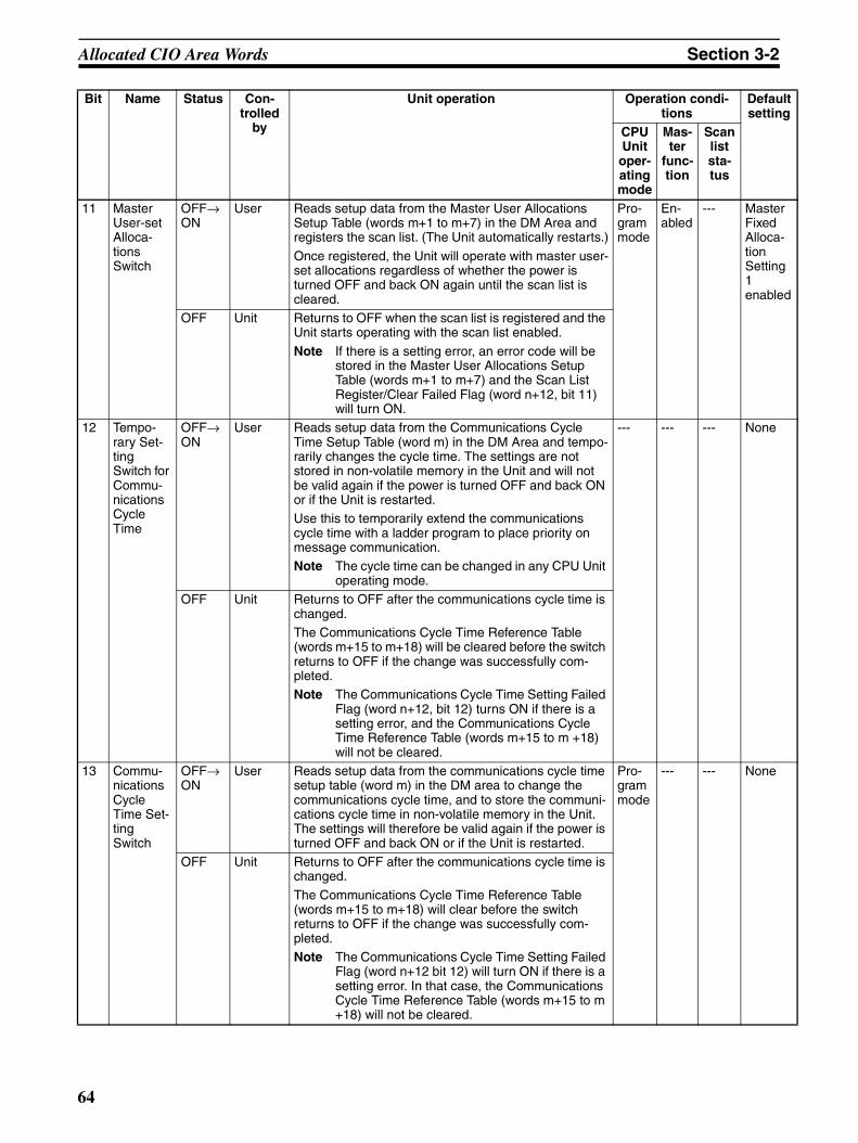
Allocated CIO Area Words Section 3-2
11 Master User-set Alloca-tions Switch
OFF→ON
User Reads setup data from the Master User Allocations Setup Table (words m+1 to m+7) in the DM Area and registers the scan list. (The Unit automatically restarts.)
Once registered, the Unit will operate with master user-set allocations regardless of whether the power is turned OFF and back ON again until the scan list is cleared.
Pro-gram mode
En-abled
--- Master Fixed Alloca-tion Setting 1 enabled
OFF Unit Returns to OFF when the scan list is registered and the Unit starts operating with the scan list enabled.
Note If there is a setting error, an error code will be stored in the Master User Allocations Setup Table (words m+1 to m+7) and the Scan List Register/Clear Failed Flag (word n+12, bit 11) will turn ON.
12 Tempo-rary Set-ting Switch for Commu-nications Cycle Time
OFF→ON
User Reads setup data from the Communications Cycle Time Setup Table (word m) in the DM Area and tempo-rarily changes the cycle time. The settings are not stored in non-volatile memory in the Unit and will not be valid again if the power is turned OFF and back ON or if the Unit is restarted.Use this to temporarily extend the communications cycle time with a ladder program to place priority on message communication.Note The cycle time can be changed in any CPU Unit
operating mode.
--- --- --- None
OFF Unit Returns to OFF after the communications cycle time is changed.The Communications Cycle Time Reference Table (words m+15 to m+18) will be cleared before the switch returns to OFF if the change was successfully com-pleted.Note The Communications Cycle Time Setting Failed
Flag (word n+12, bit 12) turns ON if there is a setting error, and the Communications Cycle Time Reference Table (words m+15 to m +18) will not be cleared.
13 Commu-nications Cycle Time Set-ting Switch
OFF→ON
User Reads setup data from the communications cycle time setup table (word m) in the DM area to change the communications cycle time, and to store the communi-cations cycle time in non-volatile memory in the Unit. The settings will therefore be valid again if the power is turned OFF and back ON or if the Unit is restarted.
Pro-gram mode
--- --- None
OFF Unit Returns to OFF after the communications cycle time is changed.
The Communications Cycle Time Reference Table (words m+15 to m+18) will clear before the switch returns to OFF if the change was successfully com-pleted.Note The Communications Cycle Time Setting Failed
Flag (word n+12 bit 12) will turn ON if there is a setting error. In that case, the Communications Cycle Time Reference Table (words m+15 to m +18) will not be cleared.
Bit Name Status Con-trolled
by
Unit operation Operation condi-tions
Default setting
CPU Unit
oper-ating mode
Mas-ter
func-tion
Scan list sta-tus
64
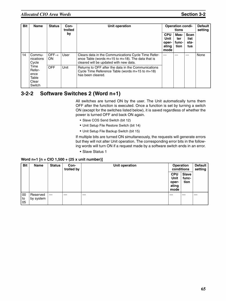
Allocated CIO Area Words Section 3-2
3-2-2 Software Switches 2 (Word n+1)All switches are turned ON by the user. The Unit automatically turns themOFF after the function is executed. Once a function is set by turning a switchON (except for the switches listed below), it is saved regardless of whether thepower is turned OFF and back ON again.
• Slave COS Send Switch (bit 12)
• Unit Setup File Restore Switch (bit 14)
• Unit Setup File Backup Switch (bit 15)
If multiple bits are turned ON simultaneously, the requests will generate errorsbut they will not alter Unit operation. The corresponding error bits in the follow-ing words will turn ON if a request made by a software switch ends in an error.
• Slave Status 1
Word n+1 [n = CIO 1,500 + (25 x unit number)]
14 Commu-nications Cycle Time Refer-ence Table Clear Switch
OFF→ON
User Clears data in the Communications Cycle Time Refer-ence Table (words m+15 to m+18). The data that is cleared will be updated with new data.
--- --- --- None
OFF Unit Returns to OFF after the data in the Communications Cycle Time Reference Table (words m+15 to m+18) has been cleared.
Bit Name Status Con-trolled
by
Unit operation Operation condi-tions
Default setting
CPU Unit
oper-ating mode
Mas-ter
func-tion
Scan list sta-tus
Bit Name Status Con-trolled by
Unit operation Operation conditions
Default setting
CPU Unit
oper-ating mode
Slave func-tion
00 to 05
Reserved by system
--- --- --- --- --- ---
65
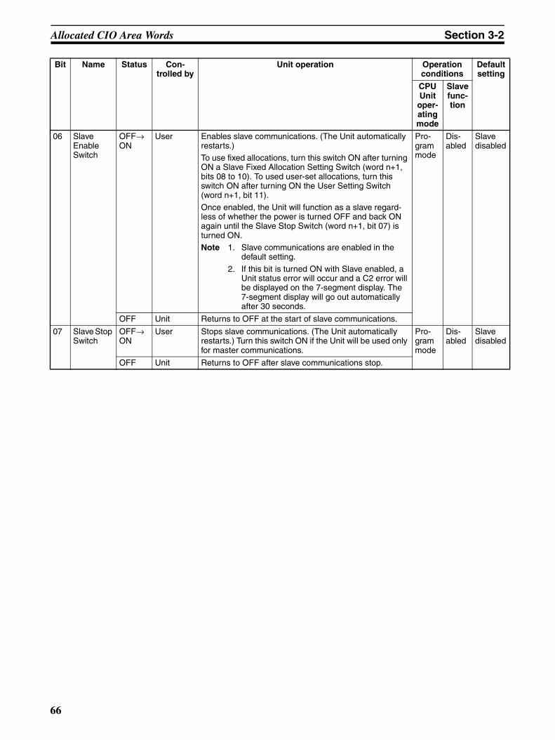
Allocated CIO Area Words Section 3-2
06 Slave Enable Switch
OFF→ON
User Enables slave communications. (The Unit automatically restarts.)To use fixed allocations, turn this switch ON after turning ON a Slave Fixed Allocation Setting Switch (word n+1, bits 08 to 10). To used user-set allocations, turn this switch ON after turning ON the User Setting Switch (word n+1, bit 11).
Once enabled, the Unit will function as a slave regard-less of whether the power is turned OFF and back ON again until the Slave Stop Switch (word n+1, bit 07) is turned ON.Note 1. Slave communications are enabled in the
default setting.
2. If this bit is turned ON with Slave enabled, a Unit status error will occur and a C2 error will be displayed on the 7-segment display. The 7-segment display will go out automatically after 30 seconds.
Pro-gram mode
Dis-abled
Slave disabled
OFF Unit Returns to OFF at the start of slave communications.
07 Slave Stop Switch
OFF→ON
User Stops slave communications. (The Unit automatically restarts.) Turn this switch ON if the Unit will be used only for master communications.
Pro-gram mode
Dis-abled
Slave disabled
OFF Unit Returns to OFF after slave communications stop.
Bit Name Status Con-trolled by
Unit operation Operation conditions
Default setting
CPU Unit
oper-ating mode
Slave func-tion
66
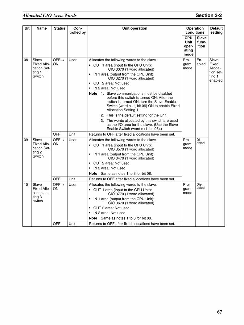
Allocated CIO Area Words Section 3-2
08 Slave Fixed Allo-cation Set-ting 1 Switch
OFF→ON
User Allocates the following words to the slave.
• OUT 1 area (input to the CPU Unit): CIO 3370 (1 word allocated)
• IN 1 area (output from the CPU Unit):CIO 3270 (1 word allocated)
• OUT 2 area: Not used• IN 2 area: Not used
Note 1. Slave communications must be disabled before this switch is turned ON. After the switch is turned ON, turn the Slave Enable Switch (word n+1, bit 06) ON to enable Fixed Allocation Setting 1.
2. This is the default setting for the Unit.
3. The words allocated by this switch are used as the I/O area for the slave. (Use the Slave Enable Switch (word n+1, bit 06).)
Pro-gram mode
En-abled
Slave Fixed Alloca-tion set-ting 1 enabled
OFF Unit Returns to OFF after fixed allocations have been set.
09 Slave Fixed Allo-cation Set-ting 2 Switch
OFF→ON
User Allocates the following words to the slave.
• OUT 1 area (input to the CPU Unit):CIO 3570 (1 word allocated)
• IN 1 area (output from the CPU Unit):CIO 3470 (1 word allocated)
• OUT 2 area: Not used• IN 2 area: Not used
Note Same as notes 1 to 3 for bit 08.
Pro-gram mode
Dis-abled
OFF Unit Returns to OFF after fixed allocations have been set.
10 Slave Fixed Allo-cation set-ting 3 switch
OFF→ON
User Allocates the following words to the slave.• OUT 1 area (input to the CPU Unit):
CIO 3770 (1 word allocated)• IN 1 area (output from the CPU Unit):
CIO 3670 (1 word allocated)• OUT 2 area: Not used• IN 2 area: Not usedNote Same as notes 1 to 3 for bit 08.
Pro-gram mode
Dis-abled
OFF Unit Returns to OFF after fixed allocations have been set.
Bit Name Status Con-trolled by
Unit operation Operation conditions
Default setting
CPU Unit
oper-ating mode
Slave func-tion
67
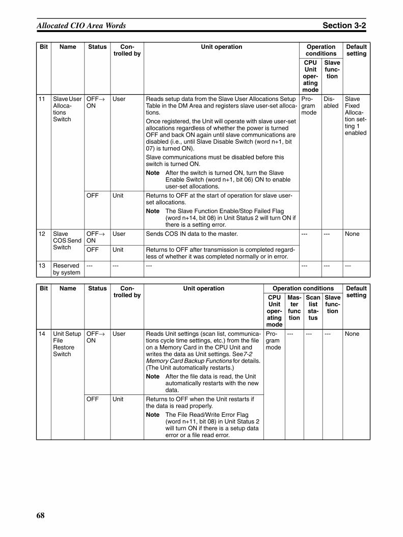
Allocated CIO Area Words Section 3-2
11 Slave User Alloca-tions Switch
OFF→ON
User Reads setup data from the Slave User Allocations Setup Table in the DM Area and registers slave user-set alloca-tions.Once registered, the Unit will operate with slave user-set allocations regardless of whether the power is turned OFF and back ON again until slave communications are disabled (i.e., until Slave Disable Switch (word n+1, bit 07) is turned ON).Slave communications must be disabled before this switch is turned ON.
Note After the switch is turned ON, turn the Slave Enable Switch (word n+1, bit 06) ON to enable user-set allocations.
Pro-gram mode
Dis-abled
Slave Fixed Alloca-tion set-ting 1 enabled
OFF Unit Returns to OFF at the start of operation for slave user-set allocations.Note The Slave Function Enable/Stop Failed Flag
(word n+14, bit 08) in Unit Status 2 will turn ON if there is a setting error.
12 Slave COS Send Switch
OFF→ON
User Sends COS IN data to the master. --- --- None
OFF Unit Returns to OFF after transmission is completed regard-less of whether it was completed normally or in error.
13 Reserved by system
--- --- --- --- --- ---
Bit Name Status Con-trolled by
Unit operation Operation conditions Default settingCPU
Unit oper-ating mode
Mas-ter
function
Scan list sta-tus
Slave func-tion
14 Unit Setup File Restore Switch
OFF→ON
User Reads Unit settings (scan list, communica-tions cycle time settings, etc.) from the file on a Memory Card in the CPU Unit and writes the data as Unit settings. See7-2 Memory Card Backup Functions for details. (The Unit automatically restarts.)Note After the file data is read, the Unit
automatically restarts with the new data.
Pro-gram mode
--- --- --- None
OFF Unit Returns to OFF when the Unit restarts if the data is read properly.
Note The File Read/Write Error Flag (word n+11, bit 08) in Unit Status 2 will turn ON if there is a setup data error or a file read error.
Bit Name Status Con-trolled by
Unit operation Operation conditions
Default setting
CPU Unit
oper-ating mode
Slave func-tion
68
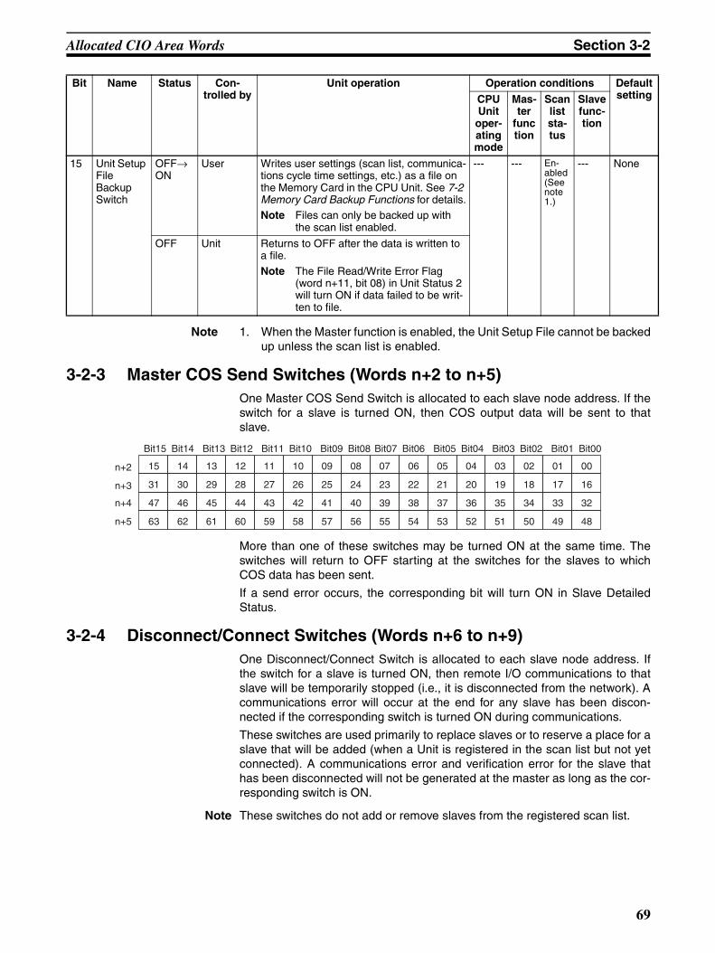
Allocated CIO Area Words Section 3-2
Note 1. When the Master function is enabled, the Unit Setup File cannot be backedup unless the scan list is enabled.
3-2-3 Master COS Send Switches (Words n+2 to n+5)One Master COS Send Switch is allocated to each slave node address. If theswitch for a slave is turned ON, then COS output data will be sent to thatslave.
More than one of these switches may be turned ON at the same time. Theswitches will return to OFF starting at the switches for the slaves to whichCOS data has been sent.
If a send error occurs, the corresponding bit will turn ON in Slave DetailedStatus.
3-2-4 Disconnect/Connect Switches (Words n+6 to n+9)One Disconnect/Connect Switch is allocated to each slave node address. Ifthe switch for a slave is turned ON, then remote I/O communications to thatslave will be temporarily stopped (i.e., it is disconnected from the network). Acommunications error will occur at the end for any slave has been discon-nected if the corresponding switch is turned ON during communications.
These switches are used primarily to replace slaves or to reserve a place for aslave that will be added (when a Unit is registered in the scan list but not yetconnected). A communications error and verification error for the slave thathas been disconnected will not be generated at the master as long as the cor-responding switch is ON.
Note These switches do not add or remove slaves from the registered scan list.
15 Unit Setup File Backup Switch
OFF→ON
User Writes user settings (scan list, communica-tions cycle time settings, etc.) as a file on the Memory Card in the CPU Unit. See 7-2 Memory Card Backup Functions for details.Note Files can only be backed up with
the scan list enabled.
--- --- En-abled (See note 1.)
--- None
OFF Unit Returns to OFF after the data is written to a file.
Note The File Read/Write Error Flag (word n+11, bit 08) in Unit Status 2 will turn ON if data failed to be writ-ten to file.
Bit Name Status Con-trolled by
Unit operation Operation conditions Default settingCPU
Unit oper-ating mode
Mas-ter
function
Scan list sta-tus
Slave func-tion
15 14 13 12 11 10 09 08 07 06 05 04 03 02 01 00
31 30 29 28 27 26 25 24 23 22 21 20 19 18 17 16
47 46 45 44 43 42 41 40 39 38 37 36 35 34 33 32
63 62 61 60 59 58 57 56 55 54 53 52 51 50 49 48
n+2
n+3
n+4
n+5
Bit15 Bit14 Bit13 Bit12 Bit11 Bit10 Bit09 Bit08 Bit07 Bit06 Bit05 Bit04 Bit03 Bit02 Bit01 Bit00
69

Allocated CIO Area Words Section 3-2
Remote I/O communications will restart if a user turns OFF a bit that is ON.
More than one of these switches may be turned ON at the same time. If theswitch for a slave that is not using remote I/O communications is turned ON, itwill be ignored.
A Unit that has been disconnected can still perform message communica-tions.
Turning ON this bit does not effect the communications cycle time (except thatit increases blank time in the communications cycle).
Note All Disconnect/Connect Switches are cleared and return to OFFwhen the power is turned OFF. If required, write the ladder programto turn them back ON when the power is turned ON.
15 14 13 12 11 10 09 08 07 06 05 04 03 02 01 00
31 30 29 28 27 26 25 24 23 22 21 20 19 18 17 16
47 46 45 44 43 42 41 40 39 38 37 36 35 34 33 32
63 62 61 60 59 58 57 56 55 54 53 52 51 50 49 48
n+6
n+7
n+8
n+9
Bit15 Bit14 Bit13 Bit12 Bit11 Bit10 Bit09 Bit08 Bit07 Bit06 Bit05 Bit04 Bit03 Bit02 Bit01 Bit00
Bit Name Status Controlled by
Unit operation
– Disconnect/ Connect Switch
ON User Stops remote I/O communications for the corresponding Slave.
OFF User Starts remote I/O communications for the corresponding Slave.
70

Allocated CIO Area Words Section 3-2
3-2-5 Unit Status 1 (Word n+10)Word n+10 [n = CIO 1,500 + (25 x unit number)]
Bit Name Status Controlled by
Unit operation
00 Unit Error Flag
ON Unit Displays DeviceNet Unit operating errors.This bit turns ON if any bit from 01 to 15 in Unit Status 1 turns ON. (OR of bits 01 to 15)
Usage example: When writing the ladder program for remote I/O commu-nications, set a NC input conditions for this bit to control Slave I/O pro-cessing.
OFF Unit Indicates that the an error has not occurred or turns OFF when the error has cleared.
01 Master Function Error Flag
ON Unit Indicates that a master error has occurred. (Master Status 1 (See word n+12.))The master errors are as follows:
• Verification Error Flag (word n+12, bit 00)• Structure Error Flag (word n+12, bit 01)• Remote I/O Communications Error Flag (word n+12, bit 02)• Invalid Scan List Data Flag (word n+12, bit 04)• Remote I/O Refresh Error Flag (word n+12, bit 05)
OFF Unit Indicates that the error has not occurred or turns OFF when the error has been cleared.
02 Reserved by system
--- --- ---
03 Slave Func-tion Error Flag
ON Unit Indicates that a slave error has occurred. (Slave Status 1 (See word n+14.))
The slave errors are as follows:• Remote I/O Communications Error Flag for OUT 1/ IN 1 (word n+14, bit
02)• Remote I/O Communications Error Flag for OUT 2/ IN 2 (word n+14, bit
03)• Invalid Setup Data Flag (word n+14, bit 04)• Remote I/O Refresh Error Flag (word n+14, bit 05)
OFF Unit Indicates that the error has not occurred or turns OFF when the error has been cleared.
04 Unit Mem-ory Error Flag
ON Unit Indicates an error in internal memory where the error history is stored. (The error occurs when the Unit starts up or when the error history is writ-ten.)
OFF Unit Indicates that the error has not occurred. Once this error has occurred, the bit will remain ON and will not return to OFF.
05 Bus Off Flag ON Unit Indicates that a Bus OFF error (communications were stopped by multiple transmissions) has occurred. When a Bus OFF occurs, the Unit goes offline and all communications stop (remote I/O communications stop, slave operation stop, and message communications are disabled).
OFF Unit Indicates that the error has not occurred. Once this error has occurred, the bit will remain ON and will not return to OFF.
06 Node Address Duplicated Flag
ON Unit Indicates a duplicate node address check error when the Unit starts up. The Unit goes offline and all communications stop. (Remote I/O communi-cations stop, slave operation stop, and message communications are dis-abled.)
OFF Unit Indicates that the error has not occurred. Once this error has occurred, the bit will remain ON and will not return to OFF.
71
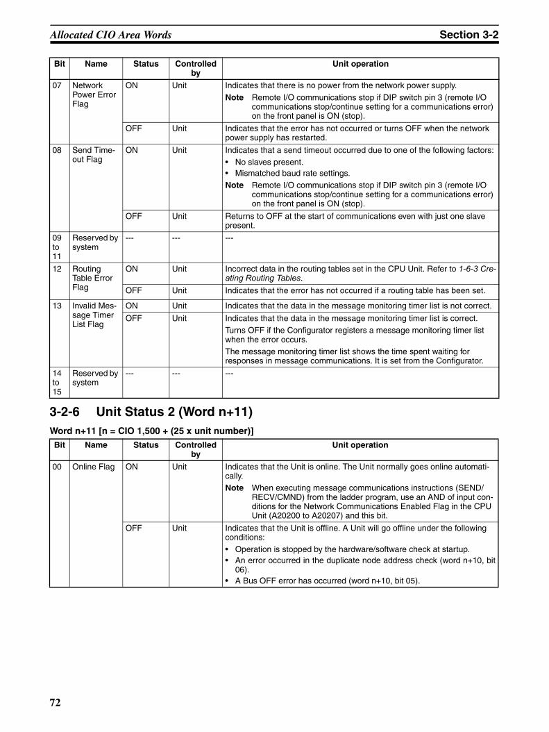
Allocated CIO Area Words Section 3-2
3-2-6 Unit Status 2 (Word n+11)Word n+11 [n = CIO 1,500 + (25 x unit number)]
07 Network Power Error Flag
ON Unit Indicates that there is no power from the network power supply.
Note Remote I/O communications stop if DIP switch pin 3 (remote I/O communications stop/continue setting for a communications error) on the front panel is ON (stop).
OFF Unit Indicates that the error has not occurred or turns OFF when the network power supply has restarted.
08 Send Time-out Flag
ON Unit Indicates that a send timeout occurred due to one of the following factors:• No slaves present.• Mismatched baud rate settings.Note Remote I/O communications stop if DIP switch pin 3 (remote I/O
communications stop/continue setting for a communications error) on the front panel is ON (stop).
OFF Unit Returns to OFF at the start of communications even with just one slave present.
09 to 11
Reserved by system
--- --- ---
12 Routing Table Error Flag
ON Unit Incorrect data in the routing tables set in the CPU Unit. Refer to 1-6-3 Cre-ating Routing Tables.
OFF Unit Indicates that the error has not occurred if a routing table has been set.
13 Invalid Mes-sage Timer List Flag
ON Unit Indicates that the data in the message monitoring timer list is not correct.
OFF Unit Indicates that the data in the message monitoring timer list is correct.Turns OFF if the Configurator registers a message monitoring timer list when the error occurs.The message monitoring timer list shows the time spent waiting for responses in message communications. It is set from the Configurator.
14 to 15
Reserved by system
--- --- ---
Bit Name Status Controlled by
Unit operation
00 Online Flag ON Unit Indicates that the Unit is online. The Unit normally goes online automati-cally.Note When executing message communications instructions (SEND/
RECV/CMND) from the ladder program, use an AND of input con-ditions for the Network Communications Enabled Flag in the CPU Unit (A20200 to A20207) and this bit.
OFF Unit Indicates that the Unit is offline. A Unit will go offline under the following conditions:• Operation is stopped by the hardware/software check at startup.• An error occurred in the duplicate node address check (word n+10, bit
06).• A Bus OFF error has occurred (word n+10, bit 05).
Bit Name Status Controlled by
Unit operation
72

Allocated CIO Area Words Section 3-2
01 Remote I/O Communica-tions Flag
ON Unit Indicates that remote I/O communications are being performed for the master function. Normally, the Unit will perform remote I/O communica-tions automatically.Note This bit only indicates the start of remote I/O communications, and
does not indicate whether data has actually been exchanged with slaves. Actual data exchange between one or more slaves is moni-tored from I/O Data Communications Flag (word n+12 bit 15). Therefore use I/O Data Communications Flag rather than this bit as the input condition in I/O processing for slaves from the ladder program.
OFF Unit Indicates remote I/O communications have stopped. This bit turns OFF in order to stop communications under the following conditions:
• No slaves are registered in the scan list.• Invalid Setup Data Flag (word n+12, bit 04)• A remote I/O communications error or sending error (network power er-
ror or send timeout error) occurred with DIP switch pin 3 (remote I/Ocommunications stop/continue setting for communications errors) on thefront panel turned ON.
• The remote I/O Communications Stop Switch (word n, bit 04) is ON.
02 Reserved by system
--- --- ---
03 Master Function Enabled Flag
ON Unit Indicates that master communications are enabled (Unit is operating as a Master) (default setting).
OFF Unit Indicates that master communications are disabled.
04 Scan List Disabled Flag
ON Unit Indicates that the Unit is operating with the scan list disabled (default set-ting).
OFF Unit Indicates that the Unit is operating with the scan list enabled.
05 Reserved by system
--- --- ---
06 Automatic Slave Connection Flag
ON Unit Indicates that the connection type was automatically set in the slave scan list.This flag is valid only with slave communications enabled.
OFF Unit Indicates that the connection type was set from the Configurator in the slave scan list.
Note The type of connection in slave communications cannot be speci-fied without the Configurator. If it is not set from the Configurator, it will be set automatically.
07 Slave Func-tion Enabled Flag
ON Unit Indicates that slave communications are enabled.
OFF Unit Indicates that slave communications are disabled (default setting).
08 File Read/Write Error Flag
ON Unit Indicates that an error has occurred when user setup data is read from a Memory Card in the CPU Unit or when data is written as a file to a Mem-ory Card.
OFF Unit Indicates that the error has not occurred. Turns OFF when the Unit has successfully completed the operation.
09 to 14
Reserved by system
--- --- ---
15 Error His-tory Flag
ON Unit Indicates that an error history has been registered. Turns ON at the first error history for the Unit.
OFF Unit Indicates that no errors have been registered in the error history. Turns OFF when the Unit receives an error history clear request.
Bit Name Status Controlled by
Unit operation
73
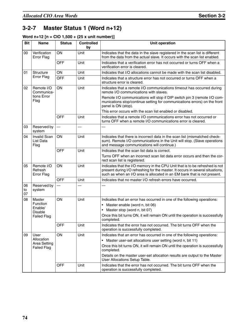
Allocated CIO Area Words Section 3-2
3-2-7 Master Status 1 (Word n+12)Word n+12 [n = CIO 1,500 + (25 x unit number)]
Bit Name Status Controlled by
Unit operation
00 Verification Error Flag
ON Unit Indicates that the data in the slave registered in the scan list is different from the data from the actual slave. It occurs with the scan list enabled.
OFF Unit Indicates that a verification error has not occurred or turns OFF when a verification error is cleared.
01 Structure Error Flag
ON Unit Indicates that I/O allocations cannot be made with the scan list disabled.
OFF Unit Indicates that a structure error has not occurred or turns OFF when a structure error is cleared.
02 Remote I/O Communica-tions Error Flag
ON Unit Indicates that a remote I/O communications timeout has occurred during remote I/O communications with slaves.Remote I/O communications will stop if DIP switch pin 3 (remote I/O com-munications stop/continue setting for communications errors) on the front panel is ON (stop).This error occurs with the scan list enabled or disabled.
OFF Unit Indicates that a remote I/O communications error has not occurred or turns OFF when a remote I/O communications error is cleared.
03 Reserved by system
--- --- ---
04 Invalid Scan List Data Flag
ON Unit Indicates that there is incorrect data in the scan list (mismatched check-sum). Remote I/O communications in the Unit will stop. (Slave operations and message communications will continue.)
OFF Unit Indicates that the scan list data is correct.Turns OFF when an incorrect scan list data error occurs and then the cor-rect scan list is registered.
05 Remote I/O Refresh Error Flag
ON Unit Indicates that the I/O memory in the CPU Unit that is to be refreshed is not present during I/O refreshing for the master. It occurs in several situations, such as when an I/O area is allocated in an EM bank that is not present.
OFF Unit Indicates that no master I/O refresh errors have occurred.
06 to 07
Reserved by system
--- --- ---
08 Master Function Enable/ Disable Failed Flag
ON Unit Indicates that an error has occurred in one of the following operations:• Master enable (word n, bit 06)• Master stop (word n, bit 07)
Once this bit turns ON, it will remain ON until the operation is successfully completed.
OFF Unit Indicates that the error has not occurred. The bit turns OFF when the operation is successfully completed.
09 User Allocation Area Setting Failed Flag
ON Unit Indicates that an error has occurred in one of the following operations:
• Master user-set allocations user setting (word n, bit 11)Once this bit turns ON, it will remain ON until the operation is successfully completed.
Details on the master user-set allocation results are output to the Master User Allocations Setup Table.
OFF Unit Indicates that the error has not occurred. The bit turns OFF when the operation is successfully completed.
74
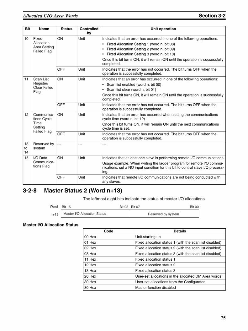
Allocated CIO Area Words Section 3-2
3-2-8 Master Status 2 (Word n+13)The leftmost eight bits indicate the status of master I/O allocations.
Master I/O Allocation Status
10 Fixed Allocation Area Setting Failed Flag
ON Unit Indicates that an error has occurred in one of the following operations:
• Fixed Allocation Setting 1 (word n, bit 08)• Fixed Allocation Setting 2 (word n, bit 09)• Fixed Allocation Setting 3 (word n, bit 10)Once this bit turns ON, it will remain ON until the operation is successfully completed.
OFF Unit Indicates that the error has not occurred. The bit turns OFF when the operation is successfully completed.
11 Scan List Register/ Clear Failed Flag
ON Unit Indicates that an error has occurred in one of the following operations:• Scan list enabled (word n, bit 00)• Scan list clear (word n, bit 01)Once this bit turns ON, it will remain ON until the operation is successfully completed.
OFF Unit Indicates that the error has not occurred. The bit turns OFF when the operation is successfully completed.
12 Communica-tions Cycle Time Setting Failed Flag
ON Unit Indicates that an error has occurred when setting the communications cycle time (word n, bit 12).
Once this bit turns ON, it will remain ON until the next communications cycle time is set.
OFF Unit Indicates that the error has not occurred. The bit turns OFF when the operation is successfully completed.
13 to 14
Reserved by system
--- --- ---
15 I/O Data Communica-tions Flag
ON Unit Indicates that at least one slave is performing remote I/O communications.Usage example: When writing the ladder program for remote I/O commu-nications, set a NO input condition for this bit to control slave I/O process-ing.
OFF Unit Indicates that remote I/O communications are not being conducted with any slaves.
Bit Name Status Controlled by
Unit operation
Code Details
00 Hex Unit starting up
01 Hex Fixed allocation status 1 (with the scan list disabled)
02 Hex Fixed allocation status 2 (with the scan list disabled)
03 Hex Fixed allocation status 3 (with the scan list disabled)
11 Hex Fixed allocation status 1
12 Hex Fixed allocation status 2
13 Hex Fixed allocation status 3
20 Hex User-set allocations in the allocated DM Area words
30 Hex User-set allocations from the Configurator
80 Hex Master function disabled
Word Bit 15 Bit 08 Bit 07 Bit 00
Master I/O Allocation Status Reserved by systemn+13
75
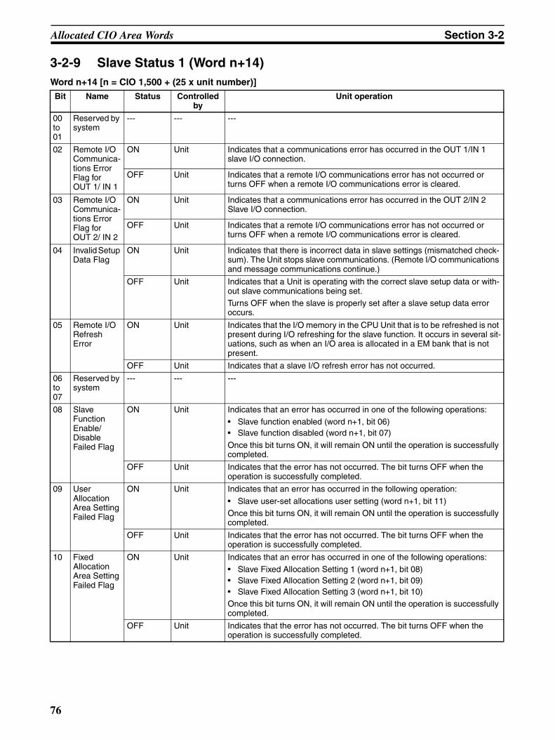
Allocated CIO Area Words Section 3-2
3-2-9 Slave Status 1 (Word n+14)Word n+14 [n = CIO 1,500 + (25 x unit number)]
Bit Name Status Controlled by
Unit operation
00 to 01
Reserved by system
--- --- ---
02 Remote I/O Communica-tions Error Flag for OUT 1/ IN 1
ON Unit Indicates that a communications error has occurred in the OUT 1/IN 1 slave I/O connection.
OFF Unit Indicates that a remote I/O communications error has not occurred or turns OFF when a remote I/O communications error is cleared.
03 Remote I/O Communica-tions Error Flag for OUT 2/ IN 2
ON Unit Indicates that a communications error has occurred in the OUT 2/IN 2 Slave I/O connection.
OFF Unit Indicates that a remote I/O communications error has not occurred or turns OFF when a remote I/O communications error is cleared.
04 Invalid Setup Data Flag
ON Unit Indicates that there is incorrect data in slave settings (mismatched check-sum). The Unit stops slave communications. (Remote I/O communications and message communications continue.)
OFF Unit Indicates that a Unit is operating with the correct slave setup data or with-out slave communications being set.Turns OFF when the slave is properly set after a slave setup data error occurs.
05 Remote I/O Refresh Error
ON Unit Indicates that the I/O memory in the CPU Unit that is to be refreshed is not present during I/O refreshing for the slave function. It occurs in several sit-uations, such as when an I/O area is allocated in a EM bank that is not present.
OFF Unit Indicates that a slave I/O refresh error has not occurred.
06 to 07
Reserved by system
--- --- ---
08 Slave Function Enable/ Disable Failed Flag
ON Unit Indicates that an error has occurred in one of the following operations:• Slave function enabled (word n+1, bit 06)• Slave function disabled (word n+1, bit 07)
Once this bit turns ON, it will remain ON until the operation is successfully completed.
OFF Unit Indicates that the error has not occurred. The bit turns OFF when the operation is successfully completed.
09 User Allocation Area Setting Failed Flag
ON Unit Indicates that an error has occurred in the following operation:
• Slave user-set allocations user setting (word n+1, bit 11)Once this bit turns ON, it will remain ON until the operation is successfully completed.
OFF Unit Indicates that the error has not occurred. The bit turns OFF when the operation is successfully completed.
10 Fixed Allocation Area Setting Failed Flag
ON Unit Indicates that an error has occurred in one of the following operations:• Slave Fixed Allocation Setting 1 (word n+1, bit 08)• Slave Fixed Allocation Setting 2 (word n+1, bit 09)• Slave Fixed Allocation Setting 3 (word n+1, bit 10)Once this bit turns ON, it will remain ON until the operation is successfully completed.
OFF Unit Indicates that the error has not occurred. The bit turns OFF when the operation is successfully completed.
76

Allocated CIO Area Words Section 3-2
11 COS Send Failed Flag
ON Unit Indicates that an attempt was made to send COS to a Master using the Slave COS send switch (Slave COS Send Switch in n+1) in Software Switches 2, but the transmission failed.The following may cause the failure of COS signal transmission.
• A COS connection was not established with a master.• Bus OFF error occurred.• A network power error occurred.• A send timeout occurred.Once this bit turns ON, it will remain ON until the operation is successfully completed.
OFF Unit Indicates that the error has not occurred. The bit turns OFF when COS is successfully sent.
12 Connection 2 Estab-lished Flag
ON Unit Indicates that an I/O connection has been established for OUT 2/IN 2. This bit turns ON even if valid I/O data has not been exchanged.
OFF Unit Indicates that an I/O connection has not been established for OUT 2/IN 2.
13 Connection 1 Estab-lished Flag
ON Unit Indicates that an I/O connection has been established for OUT 1/IN 1. This bit turns ON even if valid I/O data has not been exchanged.
OFF Unit Indicates that an I/O connection has not been established for OUT 1/IN 1.
14 Remote I/O Communica-tions Flag for OUT 2/IN 2
ON Unit Indicates that an I/O connection has been established for OUT 2/IN 2 and the slave is conducting normal remote I/O communications with the mas-ter.
OFF Unit Indicates that an I/O connection has been established for OUT 2/IN 2 and the slave is not conducting normal remote I/O communications with the master.
Usage example: When writing the ladder program for slave remote I/O communications, used a NO input conditions for this bit to control I/O pro-cessing with the master.
15 Remote I/O Communica-tions Flag for OUT 1/IN 1
ON Unit Indicates that an I/O connection has been established for OUT 1/IN 1 and the Slave is conducting normal remote I/O communications with the Mas-ter.
OFF Unit Indicates that an I/O connection has been established for OUT 1/IN 1 and the slave is not conducting normal remote I/O communications with the master.Usage example: When writing the ladder program for slave remote I/O communications, used a NO input conditions for this bit to control I/O pro-cessing with the master.
Bit Name Status Controlled by
Unit operation
77

Allocated CIO Area Words Section 3-2
3-2-10 Slave Status 2 (Word n+15)
Master Node Addresses This indicates the node address of the remote master for slave communica-tions.
Slave I/O Allocation Status This indicates the I/O allocation status of the slave.
3-2-11 Registered Slave Table (Words n+16 to n+19)This table indicates the slaves that are registered in the master scan list. Thebits correspond to node addresses. This table is updated when the Unit startsup and when a scan list is registered.
Operation with the Scan List Disabled
This table indicates the slaves to which a connection has been established atleast once. When registering a scan list using the Scan List Enable Switch(word n, bit 00), the bits corresponding to the slaves that are registered areturned ON in this table.
Operation with the Scan List Enabled
This table indicates the slaves that have been registered in the scan list.
Word Bit 15 Bit 08 Bit 07 Bit 00
Slave I/O Allocation Status Master Node Addressn+15
Name Range Details
Master Node Address
0000 to 003F Hex (0 to 63)
This information is valid when the Remote I/O Communications Flag (word n+14, bit 14 or 15) is ON in Slave Status 1.
Code Details
00 Hex Unit starting up
01 Hex Fixed Allocation Setting 1
02 Hex Fixed Allocation Setting 2
03 Hex Fixed Allocation Setting 3
20 Hex User-set allocations using allocated DM Area words
30 Hex Set from the Configurator
80 Hex Slave function disabled
15 14 13 12 11 10 09 08 07 06 05 04 03 02 01 00
31 30 29 28 27 26 25 24 23 22 21 20 19 18 17 16
47 46 45 44 43 42 41 40 39 38 37 36 35 34 33 32
63 62 61 60 59 58 57 56 55 54 53 52 51 50 49 48
n+16
n+17
n+18
n+19
Bit15 Bit14 Bit13 Bit12 Bit11 Bit10 Bit09 Bit08 Bit07 Bit06 Bit05 Bit04 Bit03 Bit02 Bit01 Bit00
Bit Name Status Controlled by
Unit operation
– Slave Registered Flags
ON Unit With the scan list disabled: Indicates slaves to which a connection has been established at least once.
With the scan list enabled: Indicates that a slave has been registered in the scan list.
OFF Unit Indicates that a slave has not been registered in the scan list.
78
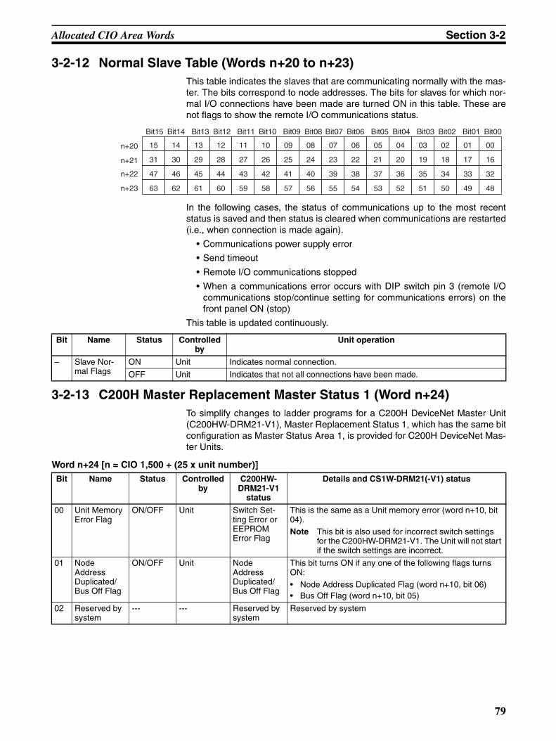
Allocated CIO Area Words Section 3-2
3-2-12 Normal Slave Table (Words n+20 to n+23)This table indicates the slaves that are communicating normally with the mas-ter. The bits correspond to node addresses. The bits for slaves for which nor-mal I/O connections have been made are turned ON in this table. These arenot flags to show the remote I/O communications status.
In the following cases, the status of communications up to the most recentstatus is saved and then status is cleared when communications are restarted(i.e., when connection is made again).
• Communications power supply error
• Send timeout
• Remote I/O communications stopped
• When a communications error occurs with DIP switch pin 3 (remote I/Ocommunications stop/continue setting for communications errors) on thefront panel ON (stop)
This table is updated continuously.
3-2-13 C200H Master Replacement Master Status 1 (Word n+24)To simplify changes to ladder programs for a C200H DeviceNet Master Unit(C200HW-DRM21-V1), Master Replacement Status 1, which has the same bitconfiguration as Master Status Area 1, is provided for C200H DeviceNet Mas-ter Units.
Word n+24 [n = CIO 1,500 + (25 x unit number)]
15 14 13 12 11 10 09 08 07 06 05 04 03 02 01 00
31 30 29 28 27 26 25 24 23 22 21 20 19 18 17 16
47 46 45 44 43 42 41 40 39 38 37 36 35 34 33 32
63 62 61 60 59 58 57 56 55 54 53 52 51 50 49 48
n+20
n+21
n+22
n+23
Bit15 Bit14 Bit13 Bit12 Bit11 Bit10 Bit09 Bit08 Bit07 Bit06 Bit05 Bit04 Bit03 Bit02 Bit01 Bit00
Bit Name Status Controlled by
Unit operation
– Slave Nor-mal Flags
ON Unit Indicates normal connection.
OFF Unit Indicates that not all connections have been made.
Bit Name Status Controlled by
C200HW- DRM21-V1
status
Details and CS1W-DRM21(-V1) status
00 Unit Memory Error Flag
ON/OFF Unit Switch Set-ting Error or EEPROM Error Flag
This is the same as a Unit memory error (word n+10, bit 04).Note This bit is also used for incorrect switch settings
for the C200HW-DRM21-V1. The Unit will not start if the switch settings are incorrect.
01 Node Address Duplicated/ Bus Off Flag
ON/OFF Unit Node Address Duplicated/ Bus Off Flag
This bit turns ON if any one of the following flags turns ON:• Node Address Duplicated Flag (word n+10, bit 06)• Bus Off Flag (word n+10, bit 05)
02 Reserved by system
--- --- Reserved by system
Reserved by system
79

Allocated CIO Area Words Section 3-2
Note Although the bit configurations are the same, the word addresses are different(because this is a CS/CJ-series CPU Bus Unit). Change the words using areplacement operation from the Programming Device.
03 Configura-tion Error Flag
ON/OFF Unit Configura-tion Error Flag
This bit turns ON if any of the following flags turn ON:• Routing Table Error Flag (word n+10, bit 12)• Invalid Message Timer List Flag (word n+10, bit 13)• Invalid Scan List Data Flag (word n+12, bit 04)• Remote I/O Refresh Error Flag (word n+12, bit 05)Note The C200HW-DRM21-V1 does not support slave
communications. Scan list data errors for slave communications are not relevant.
04 Structure Error Flag
ON/OFF Unit Structure Error Flag
This is the same as the Structure Error Flag in word n+12, bit 01.
05 Send Error Flag
ON/OFF Unit Send Error Flag
This bit turns ON if any one of the following bits turns ON:
• Network Power Error Flag (word n+10, bit 07)• Send Timeout Flag (word n+10, bit 08)
06 Communica-tions Error Flag
ON/OFF Unit Communica-tions Error Flag
This is the same as the Remote I/O Communications Flag (word n+12, bit 02).
07 Verification Error Flag
ON/OFF Unit Verification Error Flag
This is the same as the Verification Error Flag in word n+12, bit 00.
08 I/O Data Communica-tions Not Running Flag
ON/OFF Unit I/O Data Communica-tions Not Running Flag
This operates in the reverse way of the Remote I/O Com-munications Flag (word n+11 bit 01).
09 Reserved by system
--- --- Scan List Operation Completed Flag
---
10 Reserved by system
--- --- Scan List Operation Error Flag
---
11 Reserved by system
--- --- Communica-tions Error Stop Cleared Flag
---
12 Message Communica-tions Permit-ted Flag
ON/OFF Unit Message Communica-tions Permit-ted Flag
The same as the Online Flag in word n+11, bit 00.
Note When executing message communications instructions (SEND/RECV/CMND) from the ladder program, use an AND of input conditions for the Network Communications Enabled Flag in the CPU Unit (A20200 to A20207) and this bit.
13 Invalid Scan List Data Flag
ON/OFF Unit Invalid Scan List Data Flag
The same operation as the Invalid Scan List Data Flag (word n+11, bit 04).
14 Error Flag ON/OFF Unit Error Flag This bit turns ON if bit 00, 01 or 03 to 07 in this word (n+24) turns ON.
15 Remote I/O Communica-tions Flag
ON/OFF Unit Remote I/O Communica-tions Flag
The same as I/O Data Communications Flag (word n+12 bit 15).
Bit Name Status Controlled by
C200HW- DRM21-V1
status
Details and CS1W-DRM21(-V1) status
80
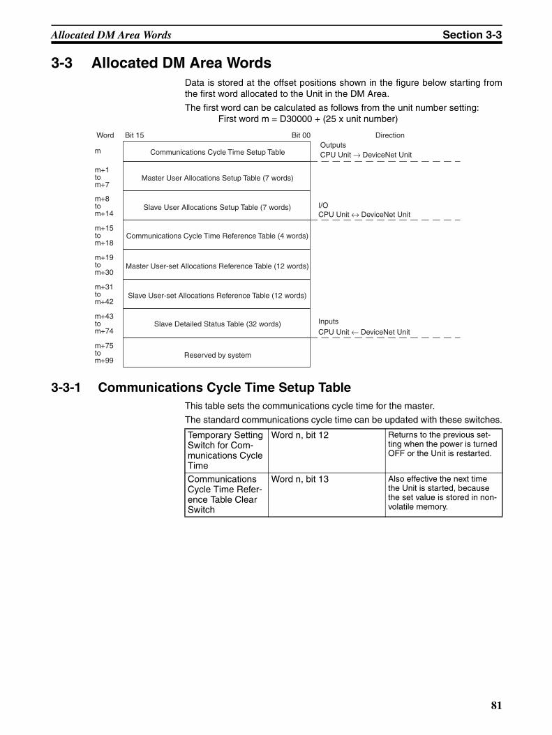
Allocated DM Area Words Section 3-3
3-3 Allocated DM Area WordsData is stored at the offset positions shown in the figure below starting fromthe first word allocated to the Unit in the DM Area.
The first word can be calculated as follows from the unit number setting:First word m = D30000 + (25 x unit number)
3-3-1 Communications Cycle Time Setup TableThis table sets the communications cycle time for the master.
The standard communications cycle time can be updated with these switches.
Word Bit 15 Bit 00 DirectionOutputsCPU Unit → DeviceNet Unit
I/OCPU Unit ↔ DeviceNet Unit
InputsCPU Unit ← DeviceNet Unit
Communications Cycle Time Setup Table
Master User Allocations Setup Table (7 words)
Slave User Allocations Setup Table (7 words)
Communications Cycle Time Reference Table (4 words)
Master User-set Allocations Reference Table (12 words)
Slave User-set Allocations Reference Table (12 words)
Slave Detailed Status Table (32 words)
Reserved by system
m+1tom+7
m+8tom+14
m+15tom+18
m+19tom+30
m+31tom+42
m+43tom+74
m+75tom+99
m
Temporary Setting Switch for Com-munications Cycle Time
Word n, bit 12 Returns to the previous set-ting when the power is turned OFF or the Unit is restarted.
Communications Cycle Time Refer-ence Table Clear Switch
Word n, bit 13 Also effective the next time the Unit is started, because the set value is stored in non-volatile memory.
81
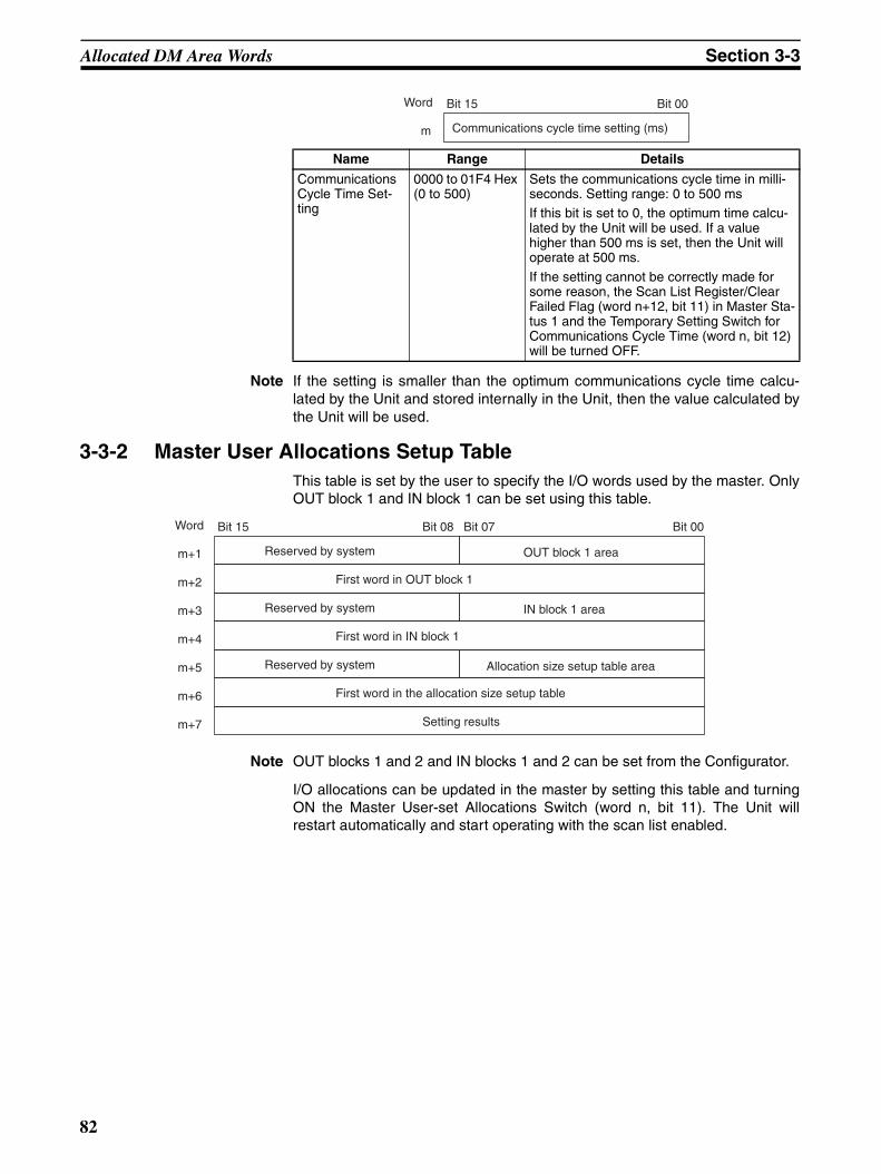
Allocated DM Area Words Section 3-3
Note If the setting is smaller than the optimum communications cycle time calcu-lated by the Unit and stored internally in the Unit, then the value calculated bythe Unit will be used.
3-3-2 Master User Allocations Setup TableThis table is set by the user to specify the I/O words used by the master. OnlyOUT block 1 and IN block 1 can be set using this table.
Note OUT blocks 1 and 2 and IN blocks 1 and 2 can be set from the Configurator.
I/O allocations can be updated in the master by setting this table and turningON the Master User-set Allocations Switch (word n, bit 11). The Unit willrestart automatically and start operating with the scan list enabled.
Name Range Details
Communications Cycle Time Set-ting
0000 to 01F4 Hex (0 to 500)
Sets the communications cycle time in milli-seconds. Setting range: 0 to 500 msIf this bit is set to 0, the optimum time calcu-lated by the Unit will be used. If a value higher than 500 ms is set, then the Unit will operate at 500 ms.
If the setting cannot be correctly made for some reason, the Scan List Register/Clear Failed Flag (word n+12, bit 11) in Master Sta-tus 1 and the Temporary Setting Switch for Communications Cycle Time (word n, bit 12) will be turned OFF.
Word Bit 15 Bit 00
Communications cycle time setting (ms)m
Word Bit 15 Bit 08 Bit 07 Bit 00
Reserved by system OUT block 1 aream+1
First word in OUT block 1m+2
Reserved by system IN block 1 aream+3
First word in IN block 1m+4
Reserved by system Allocation size setup table aream+5
First word in the allocation size setup tablem+6
Setting resultsm+7
82
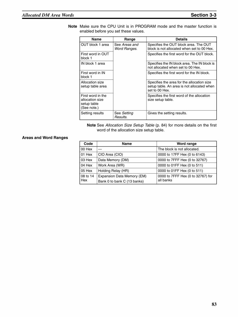
Allocated DM Area Words Section 3-3
Note Make sure the CPU Unit is in PROGRAM mode and the master function isenabled before you set these values.
Note See Allocation Size Setup Table (p. 84) for more details on the firstword of the allocation size setup table.
Areas and Word Ranges
Name Range Details
OUT block 1 area See Areas and Word Ranges.
Specifies the OUT block area. The OUT block is not allocated when set to 00 Hex.
First word in OUT block 1
Specifies the first word for the OUT block.
IN block 1 area Specifies the IN block area. The IN block is not allocated when set to 00 Hex.
First word in IN block 1
Specifies the first word for the IN block.
Allocation size setup table area
Specifies the area for the allocation size setup table. An area is not allocated when set to 00 Hex.
First word in the allocation size setup table (See note.)
Specifies the first word of the allocation size setup table.
Setting results See Setting Results.
Gives the setting results.
Code Name Word range
00 Hex --- The block is not allocated.
01 Hex CIO Area (CIO) 0000 to 17FF Hex (0 to 6143)
03 Hex Data Memory (DM) 0000 to 7FFF Hex (0 to 32767)
04 Hex Work Area (WR) 0000 to 01FF Hex (0 to 511)
05 Hex Holding Relay (HR) 0000 to 01FF Hex (0 to 511)
08 to 14 Hex
Expansion Data Memory (EM)
Bank 0 to bank C (13 banks)
0000 to 7FFF Hex (0 to 32767) for all banks
83

Allocated DM Area Words Section 3-3
Setting Results
3-3-3 Allocation Size Setup TableThe following allocation size setup tables must be set in the I/O memory in theCPU Unit to use the Master User Allocations Setup Table.
The number of bytes set in the allocation size setup table are allocated inword units in order of node addresses for OUT block 1 and then IN block 1.Set the sizes within a range from 0 to 200 bytes (100 words).
Code Description Details
0000 Hex
Completed normally ---
1101 Hex
No area • Incorrect area setting.• The allocated size in the allocation size setup
table is 0.
1103 Hex
Address range specifi-cation error
The first word is outside the setting range.
110C Hex
Parameter error • The OUT or IN size in the allocation size setuptable exceeds 200 bytes.
• Both the OUT and IN blocks are set for no allo-cations.
• No slaves are allocated.
1104 Hex
Address range over-flow
• The block or the allocation size setup table ex-ceeds the valid word range.
• The block is larger than 1,000 bytes.
2201 Hex
Wrong operating mode
The CPU Unit is not in PROGRAM mode.
2201 Hex
Unit busy Service cannot be executed because the Unit is busy.
2606 Hex
Cannot execute ser-vice
The Unit master communications have not been disabled.
Word Bit 15 Bit 08 Bit 07 Bit 00
Node address 0 OUT size (bytes) Node address 0 IN size (bytes)I
Node address 1 OUT size (bytes) Node address 1 IN size (bytes)I+1
Node address 63 OUT size (bytes) Node address 63 IN size (bytes)I+63
::
84
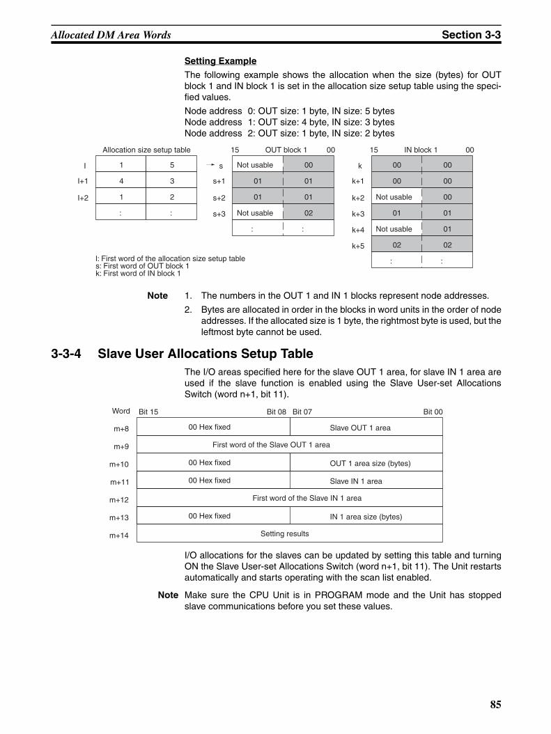
Allocated DM Area Words Section 3-3
Setting Example
The following example shows the allocation when the size (bytes) for OUTblock 1 and IN block 1 is set in the allocation size setup table using the speci-fied values.
Node address 0: OUT size: 1 byte, IN size: 5 bytesNode address 1: OUT size: 4 byte, IN size: 3 bytesNode address 2: OUT size: 1 byte, IN size: 2 bytes
Note 1. The numbers in the OUT 1 and IN 1 blocks represent node addresses.
2. Bytes are allocated in order in the blocks in word units in the order of nodeaddresses. If the allocated size is 1 byte, the rightmost byte is used, but theleftmost byte cannot be used.
3-3-4 Slave User Allocations Setup TableThe I/O areas specified here for the slave OUT 1 area, for slave IN 1 area areused if the slave function is enabled using the Slave User-set AllocationsSwitch (word n+1, bit 11).
I/O allocations for the slaves can be updated by setting this table and turningON the Slave User-set Allocations Switch (word n+1, bit 11). The Unit restartsautomatically and starts operating with the scan list enabled.
Note Make sure the CPU Unit is in PROGRAM mode and the Unit has stoppedslave communications before you set these values.
Allocation size setup table
1 5
4 3
1 2
: :
I
I+1
I+2
OUT block 1
Not usable 00
01 01
01 01
02
s
s+1
s+2
s+3
15 00
Not usable
: :
IN block 1
Not usable
00
00 00
01
00
01
k
k+1
k+2
k+3
15 00
: :
00
Not usable 01
02 02
k+4
k+5
l: First word of the allocation size setup tables: First word of OUT block 1k: First word of IN block 1
Word Bit 15 Bit 08 Bit 07 Bit 00
00 Hex fixed Slave OUT 1 aream+8
First word of the Slave OUT 1 aream+9
00 Hex fixed OUT 1 area size (bytes)m+10
m+11
First word of the Slave IN 1 aream+12
m+13
m+14
00 Hex fixed Slave IN 1 area
00 Hex fixed IN 1 area size (bytes)
Setting results
85
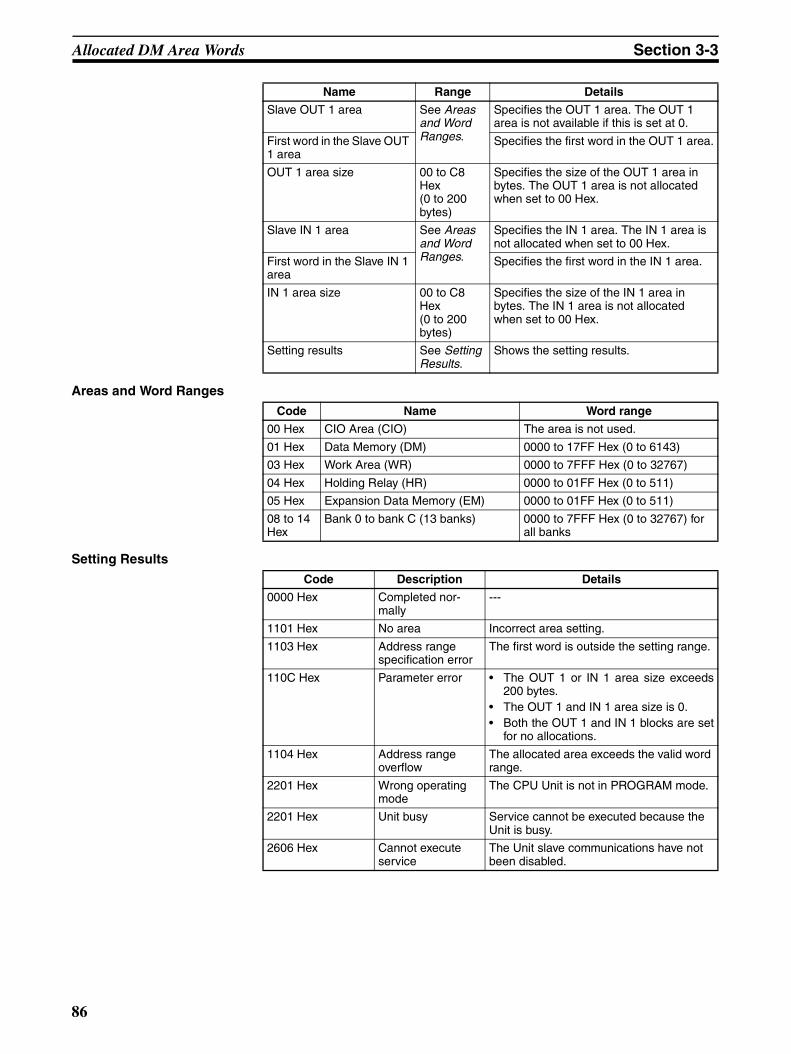
Allocated DM Area Words Section 3-3
Areas and Word Ranges
Setting Results
Name Range Details
Slave OUT 1 area See Areas and Word Ranges.
Specifies the OUT 1 area. The OUT 1 area is not available if this is set at 0.
First word in the Slave OUT 1 area
Specifies the first word in the OUT 1 area.
OUT 1 area size 00 to C8 Hex (0 to 200 bytes)
Specifies the size of the OUT 1 area in bytes. The OUT 1 area is not allocated when set to 00 Hex.
Slave IN 1 area See Areas and Word Ranges.
Specifies the IN 1 area. The IN 1 area is not allocated when set to 00 Hex.
First word in the Slave IN 1 area
Specifies the first word in the IN 1 area.
IN 1 area size 00 to C8 Hex (0 to 200 bytes)
Specifies the size of the IN 1 area in bytes. The IN 1 area is not allocated when set to 00 Hex.
Setting results See Setting Results.
Shows the setting results.
Code Name Word range
00 Hex CIO Area (CIO) The area is not used.
01 Hex Data Memory (DM) 0000 to 17FF Hex (0 to 6143)
03 Hex Work Area (WR) 0000 to 7FFF Hex (0 to 32767)
04 Hex Holding Relay (HR) 0000 to 01FF Hex (0 to 511)
05 Hex Expansion Data Memory (EM) 0000 to 01FF Hex (0 to 511)
08 to 14 Hex
Bank 0 to bank C (13 banks) 0000 to 7FFF Hex (0 to 32767) for all banks
Code Description Details
0000 Hex Completed nor-mally
---
1101 Hex No area Incorrect area setting.
1103 Hex Address range specification error
The first word is outside the setting range.
110C Hex Parameter error • The OUT 1 or IN 1 area size exceeds200 bytes.
• The OUT 1 and IN 1 area size is 0.• Both the OUT 1 and IN 1 blocks are set
for no allocations.
1104 Hex Address range overflow
The allocated area exceeds the valid word range.
2201 Hex Wrong operating mode
The CPU Unit is not in PROGRAM mode.
2201 Hex Unit busy Service cannot be executed because the Unit is busy.
2606 Hex Cannot execute service
The Unit slave communications have not been disabled.
86

Allocated DM Area Words Section 3-3
3-3-5 Communications Cycle Time Reference TableThis table can be used to access the present, maximum and minimum com-munications cycle times. All the values in this table are cleared from the Unitand the maximum and minimum values are updated with new values whenthe Communications Cycle Time Reference Table Clear Switch (word n, bit13) is turned ON.
Ranges
3-3-6 Master User-set Allocations Reference TableThe settings (area and size) for a maximum of four blocks (OUT block 1, OUTblock 2, IN block 1, and IN block 2) can be accessed in the master user-setallocations reference table.
The OUT 1 and IN 1 areas and sizes are valid even if a Configurator is notbeing used.
Word Bit 15 Bit 00
Communications cycle time setting value (ms)m+15
Communications cycle time present value (ms)m+16
Communications cycle time maximum value (ms)m+17
Communications cycle time minimum value (ms)m+18
Name Range Details
Communications cycle time set-ting value (ms)
0000 to 01F4 Hex (0 to 500)
Provide the communications cycle time setting as well as the present, maximum, and minimum commu-nications cycle time in millisec-onds. The default settings is 0000Hex (0).
Communications cycle time present value (ms)
0000 to FFFF Hex (0 to 65535)Communications cycle time maxi-
mum value (ms)
Communications cycle time mini-mum value (ms)
Word Bit 15 Bit 08 Bit 07 Bit 00
Reserved by system OUT block 1 aream+19
First word in OUT block 1m+20
No. of bytes in OUT block 1m+21
Reserved by system IN block 1 aream+22
First word in IN block 1m+23
No. of bytes in IN block 1m+24
Reserved by system OUT block 2 aream+25
First word in OUT block 2m+26
No. of bytes in OUT block 2m+27
Reserved by system IN block 2 aream+28
First word in IN block 2m+29
No. of bytes in IN block 2m+30
87
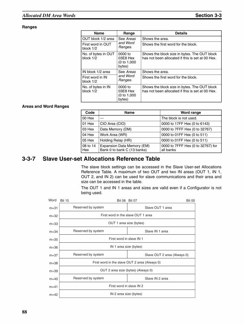
Allocated DM Area Words Section 3-3
Ranges
Areas and Word Ranges
3-3-7 Slave User-set Allocations Reference TableThe slave block settings can be accessed in the Slave User-set AllocationsReference Table. A maximum of two OUT and two IN areas (OUT 1, IN 1,OUT 2, and IN 2) can be used for slave communications and their area andsize can be accessed in the table.
The OUT 1 and IN 1 areas and sizes are valid even if a Configurator is notbeing used.
Name Range Details
OUT block 1/2 area See Areas and Word Ranges.
Shows the area.
First word in OUT block 1/2
Shows the first word for the block.
No. of bytes in OUT block 1/2
0000 to 03E8 Hex (0 to 1,000 bytes)
Shows the block size in bytes. The OUT block has not been allocated if this is set at 00 Hex.
IN block 1/2 area See Areas and Word Ranges.
Shows the area.
First word in IN block 1/2
Shows the first word for the block.
No. of bytes in IN block 1/2
0000 to 03E8 Hex (0 to 1,000 bytes)
Shows the block size in bytes. The OUT block has not been allocated if this is set at 00 Hex.
Code Name Word range
00 Hex --- The block is not used.
01 Hex CIO Area (CIO) 0000 to 17FF Hex (0 to 6143)
03 Hex Data Memory (DM) 0000 to 7FFF Hex (0 to 32767)
04 Hex Work Area (WR) 0000 to 01FF Hex (0 to 511)
05 Hex Holding Relay (HR) 0000 to 01FF Hex (0 to 511)
08 to 14 Hex
Expansion Data Memory (EM)Bank 0 to bank C (13 banks)
0000 to 7FFF Hex (0 to 32767) for all banks
Word Bit 15 Bit 08 Bit 07 Bit 00
Reserved by system Slave OUT 1 aream+31
First word in the slave OUT 1 aream+32
OUT 1 area size (bytes)m+33
Reserved by system Slave IN 1 aream+34
First word in slave IN 1m+35
IN 1 area size (bytes)m+36
Reserved by system Slave OUT 2 area (Always 0)m+37
First word in the slave OUT 2 area (Always 0)m+38
OUT 2 area size (bytes) (Always 0)m+39
Reserved by system Slave IN 2 aream+40
First word in slave IN 2m+41
IN 2 area size (bytes)m+42
88
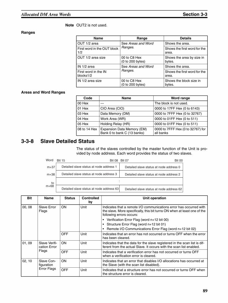
Allocated DM Area Words Section 3-3
Note OUT2 is not used.
Ranges
Areas and Word Ranges
3-3-8 Slave Detailed StatusThe status of the slaves controlled by the master function of the Unit is pro-vided by node address. Each word provides the status of two slaves.
Name Range Details
OUT 1/2 area See Areas and Word Ranges.
Shows the area.
First word in the OUT block 1/2
Shows the first word for the area.
OUT 1/2 area size 00 to C8 Hex (0 to 200 bytes)
Shows the area by size in bytes.
IN 1/2 area See Areas and Word Ranges.
Shows the area.
First word in the IN blocks1/2
Shows the first word for the area.
IN 1/2 area size 00 to C8 Hex (0 to 200 bytes)
Shows the block size in bytes.
Code Name Word range
00 Hex --- The block is not used.
01 Hex CIO Area (CIO) 0000 to 17FF Hex (0 to 6143)
03 Hex Data Memory (DM) 0000 to 7FFF Hex (0 to 32767)
04 Hex Work Area (WR) 0000 to 01FF Hex (0 to 511)
05 Hex Holding Relay (HR) 0000 to 01FF Hex (0 to 511)
08 to 14 Hex Expansion Data Memory (EM)Bank 0 to bank C (13 banks)
0000 to 7FFF Hex (0 to 32767) for all banks
Bit Name Status Controlled by
Unit operation
00, 08 Slave Error Flags
ON Unit Indicates that a remote I/O communications error has occurred with the slave. More specifically, this bit turns ON when at least one of the following errors occurs:
• Verification Error Flag (word n+12 bit 00)• Structure Error Flag (word n+12 bit 01)• Remote I/O Communications Error Flag (word n+12 bit 02)
OFF Unit Indicates that an error has not occurred or turns OFF when the error has been cleared.
01, 09 Slave Verifi-cation Error Flags
ON Unit Indicates that the data for the slave registered in the scan list is dif-ferent from the actual Slave. It occurs with the scan list enabled.
OFF Unit Indicates that a verification error has not occurred or turns OFF when a verification error is cleared.
02, 10 Slave Con-figuration Error Flags
ON Unit Indicates that an error that disables I/O allocations has occurred at the Slave (with the scan list disabled).
OFF Unit Indicates that a structure error has not occurred or turns OFF when the structure error is cleared.
Word Bit 15 Bit 08 Bit 07 Bit 00
Detailed slave status at node address 1 Detailed slave status at node address 0m+37
Detailed slave status at node address 3 Detailed slave status at node address 2m+38
Detailed slave status at node address 63 Detailed slave status at node address 62
to m+68
:
89
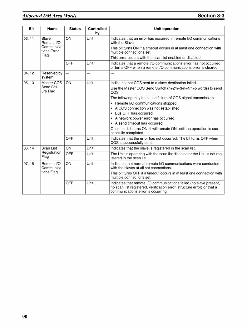
Allocated DM Area Words Section 3-3
03, 11 Slave Remote I/O Communica-tions Error Flag
ON Unit Indicates that an error has occurred in remote I/O communications with the Slave.This bit turns ON if a timeout occurs in at least one connection with multiple connections set.
This error occurs with the scan list enabled or disabled.
OFF Unit Indicates that a remote I/O communications error has not occurred or turns OFF when a remote I/O communications error is cleared.
04, 12 Reserved by system
--- --- ---
05, 13 Master COS Send Fail-ure Flag
ON Unit Indicates that COS sent to a slave destination failed.Use the Master COS Send Switch (n+2/n+3/n+4/n+5 words) to send COS.The following may be cause failure of COS signal transmission.• Remote I/O communications stopped• A COS connection was not established• Bus OFF has occurred.• A network power error has occurred.• A send timeout has occurred.
Once this bit turns ON, it will remain ON until the operation is suc-cessfully completed.
OFF Unit Indicates that the error has not occurred. The bit turns OFF when COS is successfully sent.
06, 14 Scan List Registration Flag
ON Unit Indicates that the slave is registered in the scan list.
OFF Unit The Unit is operating with the scan list disabled or the Unit is not reg-istered in the scan list.
07, 15 Remote I/O Communica-tions Flag
ON Unit Indicates that normal remote I/O communications were conducted with the slaves at all set connections.This bit turns OFF if a timeout occurs in at least one connection with multiple connections set.
OFF Unit Indicates that remote I/O communications failed (no slave present, no scan list registered, verification error, structure error) or that a communications error is occurring.
Bit Name Status Controlled by
Unit operation
90

SECTION 4Remote I/O Master Communications
This section describes the remote I/O communications performed as a DeviceNet master by the Devicenet Unit.
4-1 Master Remote I/O Communications . . . . . . . . . . . . . . . . . . . . . . . . . . . . . . . 92
4-1-1 Allocations . . . . . . . . . . . . . . . . . . . . . . . . . . . . . . . . . . . . . . . . . . . . 92
4-1-2 Remote I/O Master Specifications . . . . . . . . . . . . . . . . . . . . . . . . . . 95
4-1-3 Precautions on the Number of Master Units. . . . . . . . . . . . . . . . . . . 96
4-1-4 Procedure for Using Remote I/O Master . . . . . . . . . . . . . . . . . . . . . 97
4-2 Scan List . . . . . . . . . . . . . . . . . . . . . . . . . . . . . . . . . . . . . . . . . . . . . . . . . . . . . 99
4-3 Fixed Allocations . . . . . . . . . . . . . . . . . . . . . . . . . . . . . . . . . . . . . . . . . . . . . . 101
4-3-1 Allocated Words . . . . . . . . . . . . . . . . . . . . . . . . . . . . . . . . . . . . . . . . 101
4-3-2 Procedure . . . . . . . . . . . . . . . . . . . . . . . . . . . . . . . . . . . . . . . . . . . . . 102
4-3-3 Changing System Components. . . . . . . . . . . . . . . . . . . . . . . . . . . . . 105
4-3-4 Fixed Allocations Example. . . . . . . . . . . . . . . . . . . . . . . . . . . . . . . . 105
4-4 User-set Allocations . . . . . . . . . . . . . . . . . . . . . . . . . . . . . . . . . . . . . . . . . . . . 107
4-5 Starting and Stopping Remote I/O Communications . . . . . . . . . . . . . . . . . . . 116
4-5-1 Starting Remote I/O Communications . . . . . . . . . . . . . . . . . . . . . . . 116
4-5-2 Stopping Remote I/O Communications . . . . . . . . . . . . . . . . . . . . . . 116
4-5-3 Restarting Remote I/O Communications . . . . . . . . . . . . . . . . . . . . . 116
4-6 Example of Ladder Programming for Remote I/O Communications . . . . . . . 116
4-7 Errors that May Occur in Remote I/O Communications . . . . . . . . . . . . . . . . 118
91

Master Remote I/O Communications Section 4-1
4-1 Master Remote I/O CommunicationsRemote I/O communications are used to automatically transfer data betweenslaves and the CPU Unit without any special programming in the CPU Unitunder which the Master Unit is mounted.
Master Communications
Note 1. A CS/CJ-series DeviceNet Unit can function as either a master or slave inremote I/O communications and it can even function as both a master anda slave at the same time. Turn ON the Master Enable Switch (word n, bit06) in the Software Switches in the words allocated in the CIO Area to setthe CS/CJ-series DeviceNet Unit to function as a master. Once this switchis turned ON and master communications are enabled, the Unit will contin-ue to perform master communications regardless of whether the power isturned OFF and back ON again. Turn ON the Master Stop Switch (word n,bit 07) to stop master communications. Master communications are the fo-cus of this section.
2. In the following descriptions, a CS/CJ-series DeviceNet Unit set to functionas a master is referred to as a “Master Unit” and a CS/CJ-series DeviceNetUnit set to function as a slave is referred to as a “Slave Unit”.
4-1-1 AllocationsAll slaves are allocated words in the I/O memory of the CPU Unit to which theMaster Unit is mounted. They are allocated using one of the following meth-ods:
1) Fixed allocations
2) User-set allocations
CS/CJ-series CPU Unit
Remote I/O communicationsDeviceNet
Slaves
CS/CJ-series DeviceNet Unit (master)
92

Master Remote I/O Communications Section 4-1
Fixed AllocationsAny one of the three areas below can be specified as the words allocated inthe CIO Area for fixed allocations. The output (OUT) block and the input (IN)block are allocated strictly in order of node addresses in one of the areasshown below.
Words are allocated to slaves starting from address 0 in the output (OUT) andIN blocks. Each address is allocated at least one byte (rightmost).
• More than one word is allocated for each slave (according to its nodeaddress) with more than16 I/O points.
• The rightmost byte of the word is allocated to each slave that has lessthan 16 I/O points.
User-set AllocationsThe following methods are used for user-set allocations:
• Using a Master User Allocations Table (allocated DM Area words)
• Using the Configurator
Using the Master User Allocations Table
In the Master User Allocations Table, set the areas and first words for the out-put block (OUT 1) and the input block (IN 1) and set the area and first word forthe Allocation Size Setup Table. In the Allocation Size Setup Table, set theallocation sizes for the slave input and output blocks. Each slave can be allo-cated two blocks, OUT 1 and IN 1, according to the settings in these tables.
Select one.
CS/CJ Series
IN block 1
OUT block 2
IN block 2
OUT block 3
IN block 3
Address 0
To Slaves
From Slaves
OUT block 1
Address 1
Address 62Address 63
Address 0Address 1
Address 62Address 63
Address 0Address 1
Address 62Address 63
Address 0Address 1
Address 62Address 63
Address 0Address 1
Address 62Address 63
Address 0Address 1
Address 62Address 63
To Slaves
From Slaves
To Slaves
From Slaves
CIO 3200
CIO 3201
CIO 3262
CIO 3263
CIO 3300
CIO 3301
CIO 0362
CIO 0363
CIO 3400
CIO 3401
CIO 3462
CIO 3463
CIO 3500
CIO 3501
CIO 3562
CIO 3563
CIO 3600
CIO 3601
CIO 3662
CIO 3663
CIO 3700
CIO 3701
CIO 3762
CIO 3763
93

Master Remote I/O Communications Section 4-1
The OUT and IN blocks will be allocated in order of slave node addresses.Each block is a maximum of 500 words.
Each address is allocated at least one byte (rightmost).
• More than one word is allocated for each slave with more than16 I/Opoints (according to its node address).
• The rightmost byte of the word is allocated to each slave that has lessthan 16 I/O points.
Using the Configurator When using the Configurator, each slave can be allocated four blocks: Output(OUT) blocks 1 and 2 and input blocks 1 and 2. Each block is a maximum of500 words.
Any order can be used for block allocations and for slave allocations withineach block. Each address is allocated at least one byte (rightmost).
• More than one word is allocated for each slave with more than16 I/Opoints (using it’s node address).
• The leftmost or rightmost byte of the word is allocated to each slave thathas less than 16 I/O points.
CPU Unit
Specified in allo-cated DM words
OUT block 1
IN block 1
Address
Address
Ascending order starting from address 0
To Slaves
From Slaves
Ascending order starting from address 0Address
Address
CPU UnitOutput area
OUT block 1
OUT block 2
Input area
IN block 1
IN block 2
The position of each block can be set. An or-der (such as IN block 1, OUT block 2, IN block 2 and OUT block 1) can also be used.
Address
Address
Any address order
To Slaves
From Slaves
Address
Address
Address
Address
Address
Address
Any address order
Any address order
Any address order
From Slaves
To Slaves
94
Master Remote I/O Communications Section 4-1
4-1-2 Remote I/O Master SpecificationsItem Specifications
Slave alloca-tion methods
Fixed allo-cations
Select one of the following fixed allocation areas using the Fixed Allocated Area Switches 1, 2, and 3 in the software switches in the allocated CIO Area words.
Allocated words (CIO Area)
I/O Size Fixed Alloca-tion Area Set-
ting 1
Fixed Alloca-tion Area Set-
ting 2
Fixed Alloca-tion Area Set-
ting 3
Output (OUT) area
64 words 3200 to 3263 3400 to 3463 3600 to 3663
Input (IN) area
64 words 3300 to 3363 3500 to 3563 3700 to 3763
Select one of the above areas using the software switches. All are fixed at 1 word per node address. The default setting is Fixed Allocation Area Setting 1.
User-set allocations
By allocated DM Area words
Set the areas and the first words for the OUT 1 and IN 1 blocks in the scan list Setup Table in the allocated DM Area words. Set the allocation size for each slave using the allocation size Setup Table (any words). Allocations must be in the order of node addresses.
Allocated words
The input and output areas can be the following sizes starting from any word in any of the following areas: CIO Area, WR Area, HR Area, DM, Area, or EM Area.
Output (OUT) area
500 words max. × 1 block
Input (IN) area
500 words max. × 1 block
By Configu-rator
Set the areas for the OUT 1/2 and IN 1/2 blocks, the first words, and the allo-cation sizes for all slaves using the Configurator. Blocks can be set for nodes in any order.
Allocated words
The input and output areas can be the following sizes starting from any word in any of the following areas: CIO Area, WR Area, HR Area, DM, Area, or EM Area.
Output (OUT) area
500 words max. × 2 blocks
Input (IN) area
500 words max. × 2 blocks
No. of Masters that can be mounted
Fixed allocations 3 Units max. (Unique words must be allocated using the Allocated CIO Area Words Software Switches.)
User-set allocations
By allocated DM Area words
16 Units max. (Unique words must be allocated using the user Setup Table in the allocated DM Area words.)
By Configu-rator
16 Units max. (Unique words must be allocated using the Configurator.)
Max. No. of slaves con-nected per DeviceNet Unit
Fixed allocations 63 nodes
User-set allocations
By allocated DM Area words
By Configu-rator
Max. No. of I/O points per DeviceNet Unit
Fixed allocations 2,048 pts (64 input words, 64 output words)
User-set allocations
By allocated DM Area words
16,000 pts (500 input words x 1 block, 500 output words x 1 block)
By Configu-rator
32,000 pts (500 input words x 2 blocks, 500 output words x 2 blocks)
95
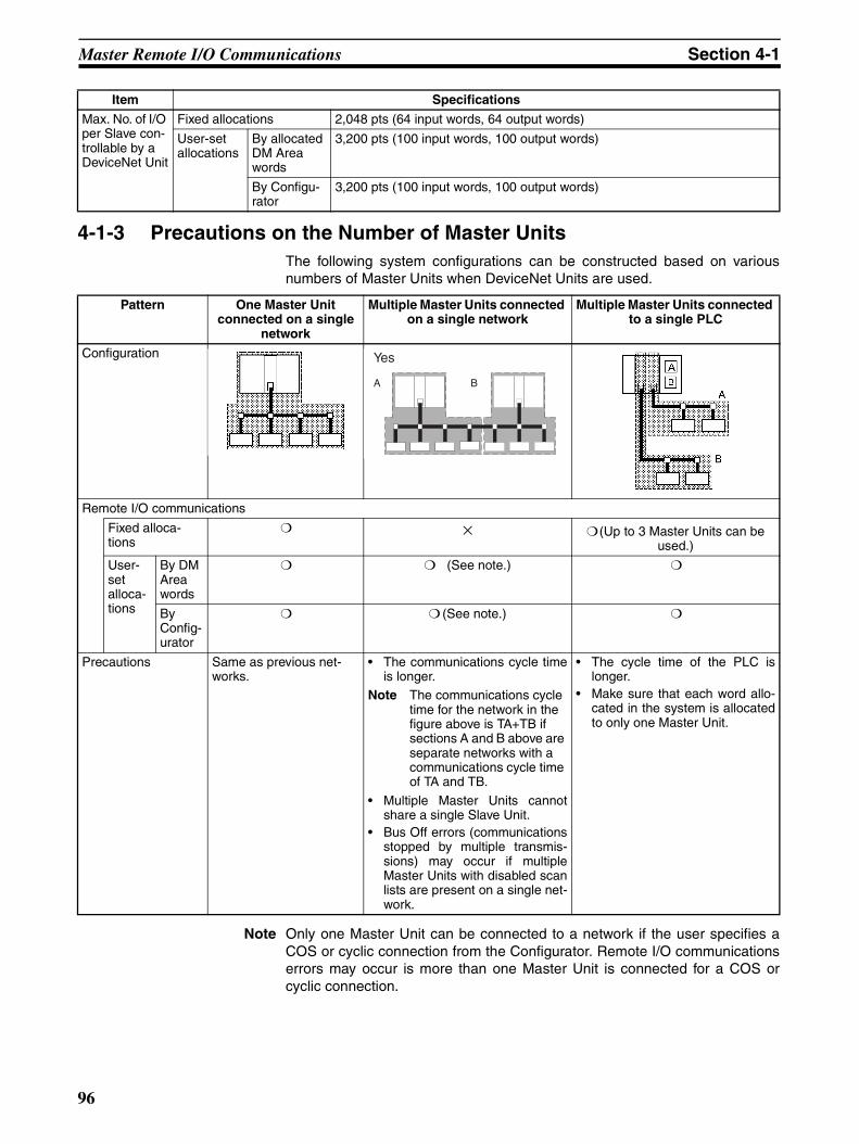
Master Remote I/O Communications Section 4-1
4-1-3 Precautions on the Number of Master UnitsThe following system configurations can be constructed based on variousnumbers of Master Units when DeviceNet Units are used.
Note Only one Master Unit can be connected to a network if the user specifies aCOS or cyclic connection from the Configurator. Remote I/O communicationserrors may occur is more than one Master Unit is connected for a COS orcyclic connection.
Max. No. of I/O per Slave con-trollable by a DeviceNet Unit
Fixed allocations 2,048 pts (64 input words, 64 output words)
User-set allocations
By allocated DM Area words
3,200 pts (100 input words, 100 output words)
By Configu-rator
3,200 pts (100 input words, 100 output words)
Item Specifications
Pattern One Master Unit connected on a single
network
Multiple Master Units connected on a single network
Multiple Master Units connected to a single PLC
Configuration
Remote I/O communications
Fixed alloca-tions
× (Up to 3 Master Units can be used.)
User-set alloca-tions
By DM Area words
(See note.)
By Config-urator
(See note.)
Precautions Same as previous net-works.
• The communications cycle timeis longer.
Note The communications cycle time for the network in the figure above is TA+TB if sections A and B above are separate networks with a communications cycle time of TA and TB.
• Multiple Master Units cannotshare a single Slave Unit.
• Bus Off errors (communicationsstopped by multiple transmis-sions) may occur if multipleMaster Units with disabled scanlists are present on a single net-work.
• The cycle time of the PLC islonger.
• Make sure that each word allo-cated in the system is allocatedto only one Master Unit.
Yes
A B
96

Master Remote I/O Communications Section 4-1
4-1-4 Procedure for Using Remote I/O MasterFixed Allocations for Remote I/O
1,2,3... 1. Turn ON the communications, slave, and PLC power supplies.
Note Turn ON the communications power supply prior to turning ON theslave power supply or the slaves may not go online.
2. Switch the CPU Unit to PROGRAM mode.
3. Turn ON the Master Enable Switch (word n, bit 06). (The master will remainenabled even if the power is turned OFF and back ON again.)
Note Execute this only when master communications are turned OFF. (Ifthe Master Enable Switch is turned ON when master communica-tions are enabled, a Unit error will occur and a C2 error will be dis-played on the 7-segment display on the front panel.)
4. Perform the following steps to start with the scan list disabled.
Skip to step 5. to re-register and enable the scan list.
Skip to step 6. to start with the scan list enabled without any changes tothe fixed allocations or scan list.
Note The mode can be confirmed from the dots on the 7-segment displayon the Master Unit.Left dot not lit: Scan list enabledLeft dot flashing: Scan list disabled
a) Turn ON a Master Fixed Allocation Setting Switch (word n, bits 08 to10).
b) Monitor and check the registered slave data area to see if communica-tions are possible with registered slaves.
c) Turn ON the Scan List Enable Switch (word n bit 00) from a Program-ming Device.
d) Go to step 6.
5. Perform the following steps to re-register the scan list when starting withthe scan list enabled.
a) Turn ON the Scan List Clear Switch (word n, bit 01) from a Program-ming Device.
b) Turn ON a Master Fixed Allocation Setting Switch (word n, bits 08 to10).
c) Monitor and check the registered slave data area to see if communica-tions are possible with registered slaves.
d) Turn ON the Scan List Enable Switch (word n, bit 00) from a Program-ming Device.
6. Start master remote I/O communications with the scan list enabled. Usethe software switches to start or stop communications.
7. Check to see if both the MS and NS indicators are lit green on the masterand all slaves.
8. Switch the CPU Unit to RUN mode.
User-set Remote I/O Allocations Using DM Area Settings
1,2,3... 1. Turn ON the communications, slave, and PLC power supplies.
Note Turn ON the communications power supply prior to turning ON theslave power supply or the slaves may not go online.
2. Switch the CPU Unit to PROGRAM mode.
97

Master Remote I/O Communications Section 4-1
3. Turn ON the Master Enable Switch (word n bit 06). (The master will remainenabled even if the power is turned OFF and back ON again.)
Note Execute this only when master communications are turned OFF. (Ifthe Master Enable Switch is turned ON when master communica-tions are enabled, a Unit error will occur and a C2 error will be dis-played on the 7-segment display on the front panel.)
4. Set data in the Master User Allocation Setup Table (words m+1 to m+6)and the Allocation Size Setup Table in the DM Area words allocated to theUnit from the PLC Programming Device.
5. Turn ON the Master User-set Allocations Switch (word n, bit 11).
6. Start master remote I/O communications with the scan list enabled. Usethe software switches to start or stop communications.
7. Check to see if both the MS and NS indicators are lit green on the masterand all slaves.
Note The mode can be confirmed from the dots on the 7-segment displayon the Master Unit.Left dot not lit: Scan list enabledLeft dot flashing: Scan list disabled
8. Switch the CPU Unit to RUN mode.
User-set Remote I/O Allocations Using the Configurator
1,2,3... 1. Connect the Configurator to the network through a serial line or dedicatedBoard/Card.
2. Turn ON the communications, slave, and PLC power supplies.
Note Turn ON the communications power supply prior to turning ON theslave power supply or the slaves may not go online.
3. Switch the CPU Unit to PROGRAM mode.
4. Perform the following steps to allocate areas, create scan lists, and down-load the settings to the nodes.
a) Create a network configuration offline on the Configurator.
b) Enable master communications in the CS1W-DRM21(-V1) properties.
c) Create master device parameters.
d) Save the data as a network component file.
Note If desired, you can also go directly online and download the networkcomponent file to the network devices without saving the file.
e) Read the network component file, go online, and download the file tothe network devices.
5. Start master remote I/O communications with the scan list enabled. Usethe software switches to start or stop communications.
6. Check to see if both the MS and NS indicators are lit green on the MasterUnit and all Slave Units.
Note The mode can be confirmed from the dots on the 7-segment displayon the Master Unit.Left dot not lit: Scan list enabledLeft dot flashing: Scan list disabled
7. Read the network components using the Configurator.
8. Save the components as a network component file using the Configurator.
9. Switch the CPU Unit to RUN mode.
Note 1. Remote I/O communications with a specified slave can be stopped to ef-fectively disconnect the slave from the network by turning ON the Discon-
98

Scan List Section 4-2
nect/Connect Switch for that slave (words n+6 to n+9). This can be donewhen a slave is replaced or to register a slave in the scan list in prepara-tions to connect it to the network at a later time. The Disconnect/ConnectSwitches, however, are cleared when the power supply is turned OFF, sothe bit must be turned back ON from the ladder program after the powerturns ON in order for it to remain effective.
2. Use Configurator Ver. 2.10 or later for the CJ1W-DRM21.
4-2 Scan ListA scan list is used to register the slaves with which the Master Unit communi-cates in DeviceNet remote I/O communications. It is the basis on which theMaster Unit communicates with slaves.
The Master Unit does not contain a scan list by default. The CS/CJ-seriesDeviceNet Unit, however, has a default setting that allows it to communicatewith all slaves even with the scan list disabled, but this operating mode shouldnot be used for normal operation. Always create a scan list prior to operatingthe Unit.
Scan List Contents The contents of the scan list is listed in the following table. When a MasterUnit goes online, it compares each of these items with the slaves that areactually connected to the network. The items that are compared, however, willdepend on the allocation method that is used.
Item Description Fixed allocations User-set allocations using allocated DM
Area words
User-set allocations from the
Configurator
Node address Node address for every Slave
Compared Compared
Allocated IN/OUT sizes and allocation
Settings of the num-ber of bytes allocated to every slave in a data area of the Master Unit
Compared Compared
Vendor Unique manufacturer ID
Not compared Set from Configurator
Device type Unique product type value
Not compared Set from Configurator
Product code Unique product model value
Not compared Set from Configurator
Connection type Applicable DeviceNet protocol(See Appendix B DeviceNet Connec-tions for details.)
Automatically set Automatically set or set from Configurator
Connection path Type of slave I/O data
(See Appendix B DeviceNet Connec-tions for details.)
Cannot be set Set from Configurator
99
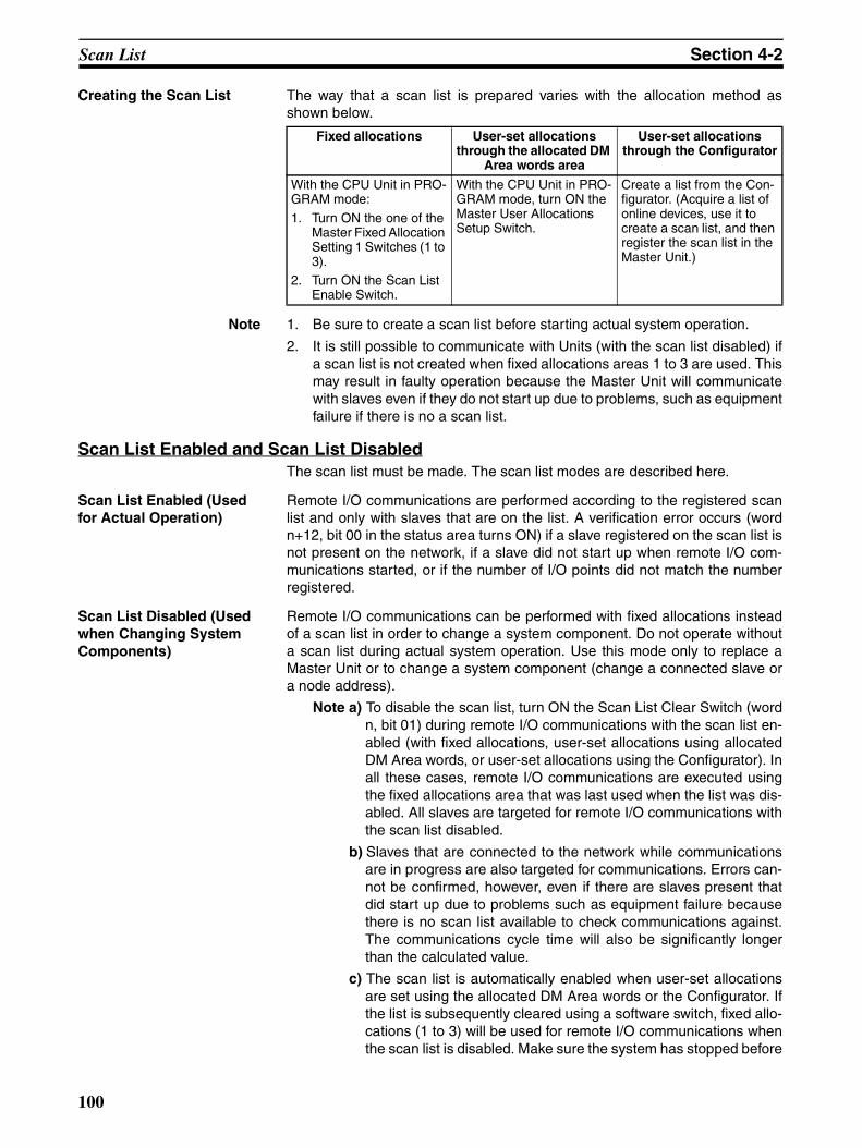
Scan List Section 4-2
Creating the Scan List The way that a scan list is prepared varies with the allocation method asshown below.
Note 1. Be sure to create a scan list before starting actual system operation.
2. It is still possible to communicate with Units (with the scan list disabled) ifa scan list is not created when fixed allocations areas 1 to 3 are used. Thismay result in faulty operation because the Master Unit will communicatewith slaves even if they do not start up due to problems, such as equipmentfailure if there is no a scan list.
Scan List Enabled and Scan List DisabledThe scan list must be made. The scan list modes are described here.
Scan List Enabled (Used for Actual Operation)
Remote I/O communications are performed according to the registered scanlist and only with slaves that are on the list. A verification error occurs (wordn+12, bit 00 in the status area turns ON) if a slave registered on the scan list isnot present on the network, if a slave did not start up when remote I/O com-munications started, or if the number of I/O points did not match the numberregistered.
Scan List Disabled (Used when Changing System Components)
Remote I/O communications can be performed with fixed allocations insteadof a scan list in order to change a system component. Do not operate withouta scan list during actual system operation. Use this mode only to replace aMaster Unit or to change a system component (change a connected slave ora node address).
Note a) To disable the scan list, turn ON the Scan List Clear Switch (wordn, bit 01) during remote I/O communications with the scan list en-abled (with fixed allocations, user-set allocations using allocatedDM Area words, or user-set allocations using the Configurator). Inall these cases, remote I/O communications are executed usingthe fixed allocations area that was last used when the list was dis-abled. All slaves are targeted for remote I/O communications withthe scan list disabled.
b) Slaves that are connected to the network while communicationsare in progress are also targeted for communications. Errors can-not be confirmed, however, even if there are slaves present thatdid start up due to problems such as equipment failure becausethere is no scan list available to check communications against.The communications cycle time will also be significantly longerthan the calculated value.
c) The scan list is automatically enabled when user-set allocationsare set using the allocated DM Area words or the Configurator. Ifthe list is subsequently cleared using a software switch, fixed allo-cations (1 to 3) will be used for remote I/O communications whenthe scan list is disabled. Make sure the system has stopped before
Fixed allocations User-set allocations through the allocated DM
Area words area
User-set allocations through the Configurator
With the CPU Unit in PRO-GRAM mode:
1. Turn ON the one of the Master Fixed Allocation Setting 1 Switches (1 to 3).
2. Turn ON the Scan List Enable Switch.
With the CPU Unit in PRO-GRAM mode, turn ON the Master User Allocations Setup Switch.
Create a list from the Con-figurator. (Acquire a list of online devices, use it to create a scan list, and then register the scan list in the Master Unit.)
100

Fixed Allocations Section 4-3
you disable the scan list with a Master Unit that is set for user-setallocations. Particularly when multiple Master Units are connectedto a single network, communications will not be performed suc-cessfully if even one Master Unit on the network is operating withthe scan list disabled. Once the list is disabled, the user-set allo-cations data registered in the Master Unit is lost.
Backing Up the Scan List A scan list must be created to switch the DeviceNet Unit to operation with thescan list disabled or to replace a DeviceNet Unit. It is important to back up thelist using one of the following methods:
Fixed Allocations or User-set Allocations in Allocated DM Area Words
Save the scan list as a backup file on Memory Card by turning ON the SetupFile Backup Switch (word n+1, bit 15) in the words allocated in the CIO Area.
User-set Allocations from the Configurator
Save the scan list as a backup file on Memory Card or save it either as a net-work component file and master parameter file using the Configurator. In thepreceding cases, turn ON the Setup File Restore Switch (word n+1, bit 14) inthe words allocated in the CIO Area to input setup data, such as the scan listbacked up on Memory Card, into a DeviceNet Unit.
4-3 Fixed Allocations4-3-1 Allocated Words
Words in the CS/CJ-series DeviceNet CIO Area in the CPU Unit are allocated.An area of words can be selected from one of three fixed allocation areas.Use a Software Switch to select the allocation area.
Each area is comprised of an OUT area that is used to write output data toslaves and an IN area that is used for input from slaves in remote I/O commu-nications.
A maximum of 3 DeviceNet Units can be included as masters in a single PLCbecause the three allocation areas above are set individually for fixed alloca-tions. The default setting is fixed allocations area 1.
Each OUT/IN area is allocated to a slave according to its node address asshown below. Allocated words are determined by the node address in fixedallocations as shown.
Area OUT area (word) IN area (word) Selection method
Fixed allocation area 1 CIO 3200 to CIO 3263 CIO 3300 to CIO 3363 Turn ON the Master Fixed Allocation Setting 1 Switch (word n, bit 08).
Fixed allocation area 2 CIO 3400 to CIO 3463 CIO 3500 to CIO 3563 Turn ON the Master Fixed Allocation Setting 2 Switch (word n, bit 09).
Fixed allocation area 3 CIO 3600 to CIO 3663 CIO 3700 to CIO 3763 Turn ON the Master Fixed Allocation Setting 3 Switch (word n, bit 10).
Area 3 Area 2 Area 1 OUT areaNode address IN area Area 1 Area 2 Area 3
CIO 3600 CIO 3400 CIO 3200 CIO 3300 CIO 3500 CIO 3700CIO 3601 CIO 3401 CIO 3201 CIO 3301 CIO 3501 CIO 3701CIO 3602 CIO 3402 CIO 3202 CIO 3302 CIO 3502 CIO 3702
CIO 3661 CIO 3461 CIO 3261 CIO 3361 CIO 3561 CIO 3761CIO 3662 CIO 3462 CIO 3262 CIO 3362 CIO 3562 CIO 3762CIO 3663 CIO 3463 CIO 3263 CIO 3363 CIO 3563 CIO 3763
101

Fixed Allocations Section 4-3
Note More than one Master Unit can be included in a single PLC with fixed alloca-tions, as shown below (3 Units max.).
4-3-2 ProcedureStep 1: Place the CPU Unit in PROGRAM mode.Step 2: Turn ON the Master Enable Switch
If the master communications have been disabled (if Master Function EnableFlag (word n+11, bit 03) is OFF), turn ON the Master Enable Switch (word n,bit 06) to enable master communications. Once Master communications havebeen enabled by turning this switch ON, it will not change even if the power isturned OFF and back ON again.
Note If the master communications are enabled (if Master Function En-able Flag (word n+11, bit 03) is ON), skip this step and go onto thenext step. (If the Master Enable Switch is turned ON when mastercommunications are enabled, a Unit error will occur and a C2 errorwill be displayed on the 7-segment display on the front panel.)
Step 3: Turn ON the Scan List Clear Switch
If the Unit is in the Scan List Enable mode (if Scan List Disabled Flag (wordn+11, bit 04) is OFF), turn ON the Scan List Clear Switch (word n, bit 01) tochange to the Scan List Disable mode.
Note If the Unit is already in the Scan List Disable mode (if the Scan ListDisabled Flag (word n+11, bit 04) is ON), skip this step and go ontothe next step. (If the Scan List Clear Switch is turned ON when theUnit is in the Scan List Disable mode, a Unit error will occur and a C2error will be displayed on the 7-segment display on the front panel.)
Step 4: Select Fixed Allocations Area 1 to 3
Turn ON the Master Fixed Allocation Setting 1 to 3 Switch (word n, bits 08 to10) in the Software Switches in the words allocated in the CIO Area to selectthe fixed allocations area from1 to 3. One word will be allocated per nodeaddress in order of node addresses for the output (OUT) block and one wordfor the input (IN) block in the CS/CJ-series DeviceNet CIO Area.
First word n = CIO 1500 + (25 x unit number)
Step 5: Turn ON the Scan List Enable Switch
Remote I/O communications will start with the scan list disabled after a fixedallocations area has been selected. Check to see if communication is pro-ceeding normally with each slave, and then turn ON the Scan List EnableSwitch (word n, bit 00) to communicate with the scan list enabled.
Master UnitMaster Unit
Slave
Slave
Software Switch address
Software Switch name Fixed allocations area number
Allocated OUT area
Allocated IN area
Word n, bit 08 Master Fixed Allocation Setting 1 Switch
Fixed allocations area 1
CIO 3200 to CIO 3263
CIO 3300 to CIO 3363
Word n, bit 09 Master Fixed Allocation Setting 2 Switch
Fixed allocations area 2
CIO 3400 to CIO 3463
CIO 3500 to CIO 3563
Word n, bit 10 Master Fixed Allocation Setting 3 Switch
Fixed allocations area 3
CIO 3600 to CIO 3663
CIO 3700 to CIO 3763
102
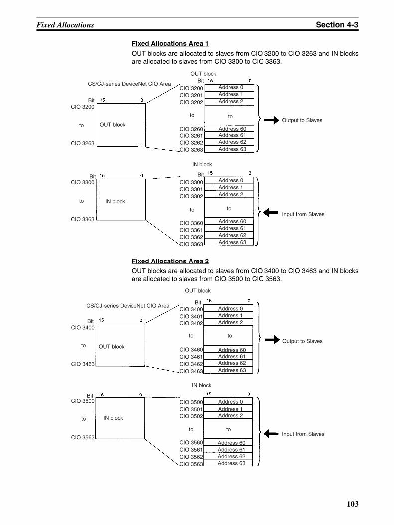
Fixed Allocations Section 4-3
Fixed Allocations Area 1
OUT blocks are allocated to slaves from CIO 3200 to CIO 3263 and IN blocksare allocated to slaves from CIO 3300 to CIO 3363.
Fixed Allocations Area 2
OUT blocks are allocated to slaves from CIO 3400 to CIO 3463 and IN blocksare allocated to slaves from CIO 3500 to CIO 3563.
CS/CJ-series DeviceNet CIO Area
Bit
Bit
OUT block
IN block
OUT blockBit
Address 0
IN block
Output to Slaves
Input from Slaves
Address 1Address 2
Address 60Address 61Address 62Address 63
Address 0Address 1Address 2
Address 60Address 61Address 62Address 63
Bit
CIO 3200
to
CIO 3263
CIO 3300
to
CIO 3363
CIO 3200
CIO 3202CIO 3201
CIO 3260
CIO 3262CIO 3261
CIO 3263
CIO 3300
CIO 3302CIO 3301
CIO 3360
CIO 3362CIO 3361
CIO 3363
to
to
to
to
CS/CJ-series DeviceNet CIO Area
Bit
Bit
OUT block
IN block
OUT block
BitAddress 0
IN block
Output to Slaves
Input from Slaves
Address 1Address 2
Address 60Address 61Address 62Address 63
Address 0Address 1Address 2
Address 60Address 61Address 62Address 63
to
to
CIO 3400
to
CIO 3463
CIO 3500
to
CIO 3563
CIO 3400CIO 3401CIO 3402
CIO 3460CIO 3461CIO 3462CIO 3463
CIO 3500CIO 3501CIO 3502
CIO 3560CIO 3561CIO 3562CIO 3563
to
to
103

Fixed Allocations Section 4-3
Fixed Allocations Area 3
OUT blocks are allocated to slaves from CIO 3600 to CIO 3663 and IN blocksare allocated to slaves from CIO 3700 to CIO 3763.
The Slave allocation order is fixed in the output (OUT) and IN blocks startingfrom address 0. Each address is allocated at least one byte (rightmost).
• More than one word is allocated for each slave (according to it’s nodeaddress) with more than16 I/O points.
• The rightmost byte of the word is allocated to each slave that has lessthan 16 I/O points.
Note The table below shows how fixed allocations areas differ between theC200HW-DM21-V1 DeviceNet Master Unit of the C200H-series, and theCS1W-DRM21(-V1) DeviceNet Unit of the CS/CJ-series and CJ1W-DRM21DeviceNet Unit of the CJ-series.
CS/CJ-series DeviceNet CIO Area
Bit
Bit
OUT block
IN block
OUT block
BitAddress 0
IN block
Output to Slaves
Input from Slaves
Address 1Address 2
Address 60Address 61Address 62Address 63
Address 0Address 1Address 2
Address 60Address 61Address 62Address 63
to
to
CIO 3600
to
CIO 3663
CIO 3700
to
CIO 3763
CIO 3600CIO 3601CIO 3602
CIO 3660CIO 3661CIO 3662CIO 3663
CIO 3700CIO 3701CIO 3702
CIO 3760CIO 3761CIO 3762CIO 3763
to
to
Item C200HW-DRM21-V1 CS1W-DRM21(-V1)/CJ1W-DRM21
Fixed allocations area
C200 DeviceNet CIO Area CS/CJ-series DeviceNet CIO Area
Output area
CIO 0050 to CIO 0099 CIO 3200 to CIO 3263CIO 3400 to CIO 3463CIO 3600 to CIO 3663
Input area CIO 0350 to CIO 0399 CIO 3300 to CIO 3363CIO 3500 to CIO 3563CIO 3700 to CIO 3763
104
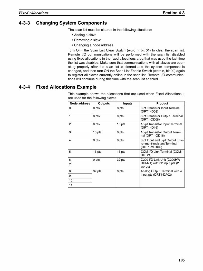
Fixed Allocations Section 4-3
4-3-3 Changing System ComponentsThe scan list must be cleared in the following situations:
• Adding a slave
• Removing a slave
• Changing a node address
Turn OFF the Scan List Clear Switch (word n, bit 01) to clear the scan list.Remote I/O communications will be performed with the scan list disabledusing fixed allocations in the fixed allocations area that was used the last timethe list was disabled. Make sure that communications with all slaves are oper-ating properly after the scan list is cleared and the system component ischanged, and then turn ON the Scan List Enable Switch (word n, bit 00) againto register all slaves currently online in the scan list. Remote I/O communica-tions will continue during this time with the scan list enabled.
4-3-4 Fixed Allocations ExampleThis example shows the allocations that are used when Fixed Allocations 1are used for the following slaves.
Node address Outputs Inputs Product
0 0 pts 8 pts 8-pt Transistor Input Terminal (DRT1-ID08)
1 8 pts 0 pts 8-pt Transistor Output Terminal (DRT1-OD08)
2 0 pts 16 pts 16-pt Transistor Input Terminal (DRT1-ID16)
3 16 pts 0 pts 16-pt Transistor Output Termi-nal (DRT1-OD16)
4 8 pts 8 pts 8-pt Input and 8-pt Output Envi-ronment-resistant Terminal (DRT1-MD16C)
5 16 pts 16 pts CQM I/O Link Terminal (CQM1-DRT21)
6 0 pts 32 pts C200 I/O Link Unit (C200HW-DRM21) with 32 input pts (2 words)
7
8 32 pts 0 pts Analog Output Terminal with 4 input pts (DRT1-DA02)9
10
11
105
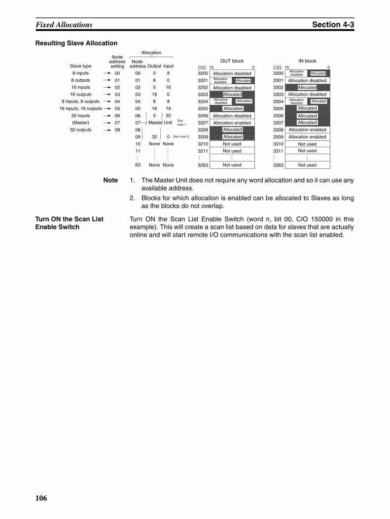
Fixed Allocations Section 4-3
Resulting Slave Allocation
Note 1. The Master Unit does not require any word allocation and so it can use anyavailable address.
2. Blocks for which allocation is enabled can be allocated to Slaves as longas the blocks do not overlap.
Turn ON the Scan List Enable Switch
Turn ON the Scan List Enable Switch (word n, bit 00, CIO 150000 in thisexample). This will create a scan list based on data for slaves that are actuallyonline and will start remote I/O communications with the scan list enabled.
Slave type
8 inputs
8 outputs
16 inputs
16 outputs
8 inputs, 8 outputs
16 inputs, 16 outputs
32 inputs
(Master)
32 outputs
Nodeaddresssetting
00
01
02
03
04
05
06
07
08
Node address
00
01
02
03
04
05
06
07
08
09
10
11
63
Output
0
8
0
16
8
16
0
32
None
None
Input
8
0
16
0
8
16
32
0
None
None
OUT block
3200
3201
3202
3203
3204
3205
3206
3207
3208
3209
3210
3211
3263
15 0
3300
3301
3302
3303
3304
3305
3306
3307
3308
3309
3310
3311
3363
Allocation
Allocated
Allocated
Allocated
Allocated
Allocated
Allocated
Allocation disabledAllocationdisabled
Allocation disabled
Allocation disabled
Allocation enabled
Not used
Not used
Not used
IN block15 0
Master Unit
See note 2.
See note 1.
Allocationdisabled
Allocationdisabled Allocated
Allocation disabled
Allocated
Allocation disabledAllocationdisabled Allocated
Allocated
AllocatedAllocated
Allocation enabled
Allocation enabled
Not used
Not usedNot used
CIO CIO
106
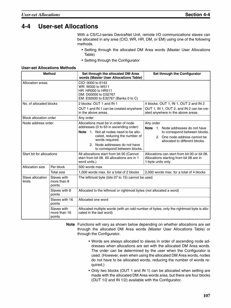
User-set Allocations Section 4-4
4-4 User-set AllocationsWith a CS/CJ-series DeviceNet Unit, remote I/O communications slaves canbe allocated in any area (CIO, WR, HR, DM, or EM) using one of the followingmethods.
• Setting through the allocated DM Area words (Master User AllocationsTable)
• Setting through the Configurator
User-set Allocations Methods
Note Functions will vary as shown below depending on whether allocations are setthrough the allocated DM Area words (Master User Allocations Table) orthrough the Configurator.
• Words are always allocated to slaves in order of ascending node ad-dresses when allocations are set with the allocated DM Area words.The order can be determined by the user when the Configurator isused. (However, even when using the allocated DM Area words, nodesdo not have to be allocated words, reducing the number of words re-quired.)
• Only two blocks (OUT 1 and IN 1) can be allocated when setting aremade with the allocated DM Area words area, but there are four blocks(OUT 1/2 and IN 1/2) available with the Configurator.
Method Set through the allocated DM Area words (Master User Allocations Table)
Set through the Configurator
Allocation areas CIO: 0000 to 6143WR: W000 to W511HR: HR000 to HR511DM: D00000 to D32767EM: E00000 to E32767 (Banks 0 to C)
No. of allocated blocks 2 blocks: OUT 1 and IN 1OUT 1 and IN 1 can be created anywhere in the above areas.
4 blocks: OUT 1, IN 1, OUT 2 and IN 2OUT 1, IN 1, OUT 2, and IN 2 can be cre-ated anywhere in the above areas.
Block allocation order Any order
Node address order Allocations must be in order of node addresses (0 to 63 in ascending order)Note 1. Not all nodes need to be allo-
cated, reducing the number of words required.
2. Node addresses do not have to correspond between blocks.
Any orderNote 1. Node addresses do not have
to correspond between blocks.
2. One node address cannot be allocated to different blocks.
Start bit for allocations All allocations start from bit 00 (Cannot start from bit 08. All allocations are in 1 word units.)
Allocations can start from bit 00 or bit 08. Allocations starting from bit 08 are in1-byte units only.
Allocation size Per block 500 words max.
Total size 1,000 words max. for a total of 2 blocks 2,000 words max. for a total of 4 blocks
Slave allocation limits
Slaves with more than 8 points
The leftmost byte (bits 07 to 15) cannot be used.
Slaves with 8 points
Allocated to the leftmost or rightmost bytes (not allocated a word)
Slaves with 16 points
Allocated one word
Slaves with more than 16 points
Allocated multiple words (with an odd number of bytes, only the rightmost byte is allo-cated in the last word)
107

User-set Allocations Section 4-4
• The first bit for node allocations is always bit 00 when setting alloca-tions with the allocated DM Area words, but can be either bit 00 or bit08 with the Configurator. (Allocations for slaves with two bytes or morecannot start at bit 08.
Setting through the Allocated DM Area Words (Master User Allocations Table)All slaves are allocated words in order of node addresses in two blocks: OUTblock 1 and IN block 1.
The block allocation order and block allocation areas can be set. Nodeaddresses in each block are allocated words in ascending order from 0 to 63.Node addresses that are not allocated are skipped (not allocated words).Each address is allocated at least one byte (rightmost byte, 1 word, or multiplewords).
• More than one word is allocated for each slave (according to it’s nodeaddress) with more than16 I/O points.
• The rightmost byte of the word is allocated to each slave that has lessthan 16 I/O points.
Note Multiple Master Units can be included in a single PLC as shown be-low using user-set allocations (16 Units max.).
Area specified in I/O memory
BitFirst word specified
BitFirst word specified
OUT block 1
IN block 1
OUT areas
BitFirst word specified
Address 0Node addresses in ascending order
Addresses are in ascending order. Not all nodes need to be allocated and addresses for nodes with no allocations are skipped.
IN areas
BitFirst word specified Address 0
Node addresses in ascending order
Output to Slaves
Input from Slaves
to
to
to to
toto
Addresses are in ascending order. Not all nodes need to be allocated and addresses for nodes with no allocations are skipped.
Master UnitMaster Unit
Slave
Slave
108
User-set Allocations Section 4-4
Procedure Step 1: Turn ON the Master Enable Switch
Make sure that master communications have disabled by checking to see ifMaster Enable Function Flag (word n+11, bit 03) is OFF and then turn ON theMaster Enable Switch (word n+14, bit 06) to enable master communications.Once master communications have been enabled by turning this switch ON,they will remain enabled even if the power is turned OFF and back ON again.
Note Do not turn ON the Master Enable Switch unless master communi-cations are stopped. (If the Master Enable Switch is turned ON whenmaster communications are enabled, a Unit error will occur and a C5error will be displayed on the 7-segment display on the front panel.)
Step 2: Setting the Master User Allocations Table
This table specifies the area and first word for each block and the area andfirst word for the Allocation Size Setup Table.
• Master User Allocations Table
• Areas and Word Ranges for OUT Block 1, IN Block 1, and the Alloca-tion Size Setup Table
Step 3: Setting the Allocation Size Setup Table
Specify the area and first word in this table at words m+5 and m+6. IN andOUT sizes for all nodes are set here as shown in the table below. The settingrange for each node is 0 to 200 bytes (0 to 100 words), although actual sizedepends on the allocated slaves. The maximum size per block is 500 words. Ifthe size set here is larger than 1 byte, the start bit for all slaves is bit 00 andsize is allocated in ascending node address order starting from the beginningof the OUT 1 and IN 1 areas in word units. If the size is set at 0 bytes for anode address, it is skipped the words are allocated to the next address.
• Allocation Size Setup Table
First word m = D30,000+(100 x unit no.)Bit
OUT block 1 area
First word of OUT block 1
IN block 1 area
First word of IN block 1Area for Allocation Size Setup Table
First word of Allocation Size Setup Table
Can be set anywhere past here.
Can be set anywhere past here.
15 08 07 00
m+1 wd
m+2 wd
m+3 wd
m+4 wd
m+5 wd
m+6 wd
0 0
0 0
0 0
Code Name Word range
00 Hex --- The block is not used.
01 Hex CIO Area (CIO) 0000 to 17FF Hex (0 to 6143)
03 Hex Data Memory (DM) 0000 to 7FFF Hex (0 to 32767)
04 Hex Work (WR) 0000 to 01FF Hex (0 to 511)
05 Hex HR (HR) 0000 to 01FF Hex (0 to 511)
08 to 14 Hex Expansion Data Memory (EM)Bank 0 to bank C (13 banks)
0000 to 7FFF Hex (0 to 32767) for all banks
109
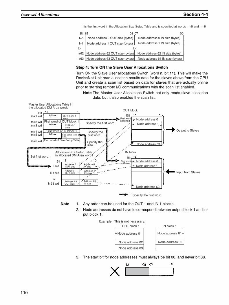
User-set Allocations Section 4-4
Step 4: Turn ON the Slave User Allocations Switch
Turn ON the Slave User allocations Switch (word n, bit 11). This will make theDeviceNet Unit read allocation results data for the slaves above from the CPUUnit and create a scan list based on data for slaves that are actually onlineprior to starting remote I/O communications with the scan list enabled.
Note The Master User Allocations Switch not only reads slave allocationdata, but it also enables the scan list.
Note 1. Any order can be used for the OUT 1 and IN 1 blocks.
2. Node addresses do not have to correspond between output block 1 and in-put block 1.
3. The start bit for node addresses must always be bit 00, and never bit 08.
l is the first word in the Allocation Size Setup Table and is specified at words m+5 and m+6
BitNode address 0 OUT size (bytes)
Node address 1 OUT size (bytes)
Node address 62 OUT size (bytes)
Node address 63 OUT size (bytes)
Node address 0 IN size (bytes)
Node address 1 IN size (bytes)
Node address 62 IN size (bytes)
Node address 63 IN size (bytes)
toto
15 08 07 00
I+0
I+1
I+62
I+63
Master User Allocations Table in the allocated DM Area words
BitOUT block 1 area
First word of OUT block 1IN block 1 area
First word of IN block 1Size Setup Table Area
First word of Size Setup Table
Specify the first word.
Specify the first word.
Specify the size.
OUT block
BitNode address 0Node address 1
Output to Slaves
Node address 63
IN block
BitFirst word specified
Node address 0
Node address 1
Node address 63
Input from Slaves
Specify the first word.
in allocated DM Area wordsSet first word.
BitAddress 0 OUT size
Address 0 IN size
Address 1 IN size
Address 1 OUT size
Address 63 OUT size
Address 63 IN size
First word specified
m+1 wd
m+2 wdm+3 wd
m+4 wdm+5 wd
m+6 wd
I wd
I+1 wd
I+63 wd
to
Allocation Size Setup Table
Example:
OUT block 1 IN block 1
Node address 01
Node address 02
Node address 03
Node address 01
Node address 02
This is not necessary.
110

User-set Allocations Section 4-4
4. Multiple masters cannot share the same slave.
5. Be sure to use user-set allocations and operate the Master Unit with thescan list enabled if multiple masters are connected to a single network.Communications will not be possible if there is more than one master withthe scan list disabled connected to a network.
Changing System Components
In the following situations, the table must be reset, the Master User Alloca-tions Switch (word n, bit 11) turned ON, and the scan list recreated:
• Adding a slave
• Removing a slave
• Changing a node address
• Changing a node allocation
There is no need to clear the scan list.
Example Settings for User-set Allocations through Allocated DM Area WordsThis example uses the following settings for unit number 0.
• OUT block 1 area and first word: WR (04 Hex), 50 (0032 Hex)
• IN block 1 area and first word: WR (04 Hex), 100 (0064 Hex)
• Allocation Size Setup Table area and first word: DM (03 Hex), 00100(0064 Hex)
This example shows user-set allocations for the following slaves.
Master User Allocations Table
Master
Slave
Master
Node address Outputs Inputs Product
0 16 pts 0 pts 16-pt Transistor Output Terminal (DRT1-OD16)
1 8 pts 8 pts 8-pt input and 8-pt Output Environment-resistant Terminal (DRT1-MD16C)
2 16 pts 16 pts CQM I/O Link Terminal (CQM1-DRT21)
3 0 pts 8 pts 8-pt Transistor Input Terminal (DRT1-ID08)
4 None ---
5 160 pts 160 pts CS/CJ-series DeviceNet Unit (CS1W-DRM21(-V1)) (Slave Unit)
OUT block 1 area: WR (04 Hex)First word of OUT block 1: 50 (0032 Hex)IN block 1 area: WR (04 Hex)
First word of IN block 1: 100 (0064 Hex)Area for the Allocation Size Setup Table: DM (03 Hex)First word of the Allocation Size Setup Table: 00100 (0064 Hex)
111
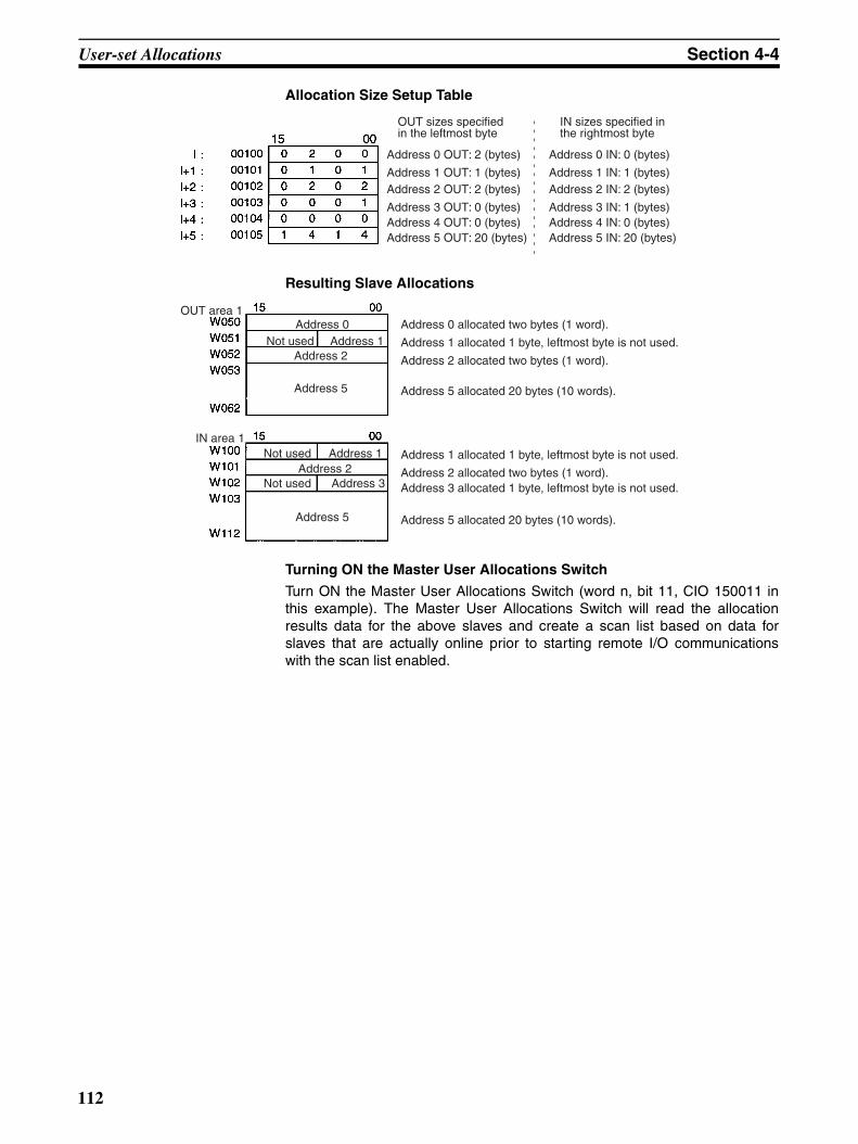
User-set Allocations Section 4-4
Allocation Size Setup Table
Resulting Slave Allocations
Turning ON the Master User Allocations Switch
Turn ON the Master User Allocations Switch (word n, bit 11, CIO 150011 inthis example). The Master User Allocations Switch will read the allocationresults data for the above slaves and create a scan list based on data forslaves that are actually online prior to starting remote I/O communicationswith the scan list enabled.
Address 0 OUT: 2 (bytes)
Address 1 OUT: 1 (bytes)Address 2 OUT: 2 (bytes)
Address 3 OUT: 0 (bytes)Address 4 OUT: 0 (bytes)Address 5 OUT: 20 (bytes)
OUT sizes specified in the leftmost byte
Address 0 IN: 0 (bytes)
Address 1 IN: 1 (bytes)Address 2 IN: 2 (bytes)
Address 3 IN: 1 (bytes)Address 4 IN: 0 (bytes)Address 5 IN: 20 (bytes)
IN sizes specified in the rightmost byte
OUT area 1
IN area 1
Address 0Not used Address 1
Address 2
Address 5
Not usedAddress 2
Not used
Address 1
Address 5
Address 0 allocated two bytes (1 word).
Address 1 allocated 1 byte, leftmost byte is not used.
Address 2 allocated two bytes (1 word).
Address 5 allocated 20 bytes (10 words).
Address 1 allocated 1 byte, leftmost byte is not used.
Address 2 allocated two bytes (1 word).Address 3 allocated 1 byte, leftmost byte is not used.
Address 5 allocated 20 bytes (10 words).
Address 3
112
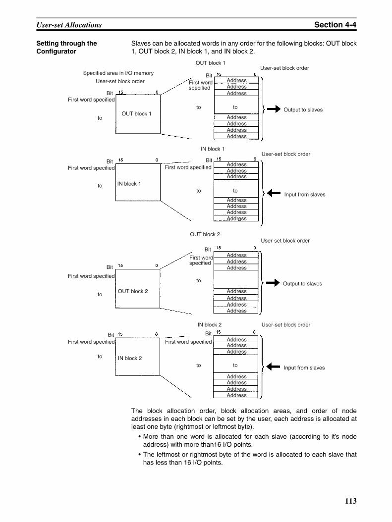
User-set Allocations Section 4-4
Setting through the Configurator
Slaves can be allocated words in any order for the following blocks: OUT block1, OUT block 2, IN block 1, and IN block 2.
The block allocation order, block allocation areas, and order of nodeaddresses in each block can be set by the user, each address is allocated atleast one byte (rightmost or leftmost byte).
• More than one word is allocated for each slave (according to it’s nodeaddress) with more than16 I/O points.
• The leftmost or rightmost byte of the word is allocated to each slave thathas less than 16 I/O points.
Specified area in I/O memory
User-set block order
BitFirst word specified
OUT block 1
BitFirst word specified
IN block 1
OUT block 1User-set block order
BitFirst word specified
Output to slaves
IN block 1User-set block order
BitFirst word specified
Input from slaves
Bit
First word specified
OUT block 2
BitFirst word specified
IN block 2
OUT block 2
Bit
First word specified
AddressAddress
IN block 2
Bit
First word specified
Address
Address
Address
AddressAddress
User-set block order
Output to slaves
User-set block order
Input from slaves
AddressAddressAddress
Address
Address
AddressAddress
AddressAddressAddress
Address
Address
AddressAddress
AddressAddressAddress
Address
Address
AddressAddress
to
to
to
to
to
to
to
to to
to
to
113
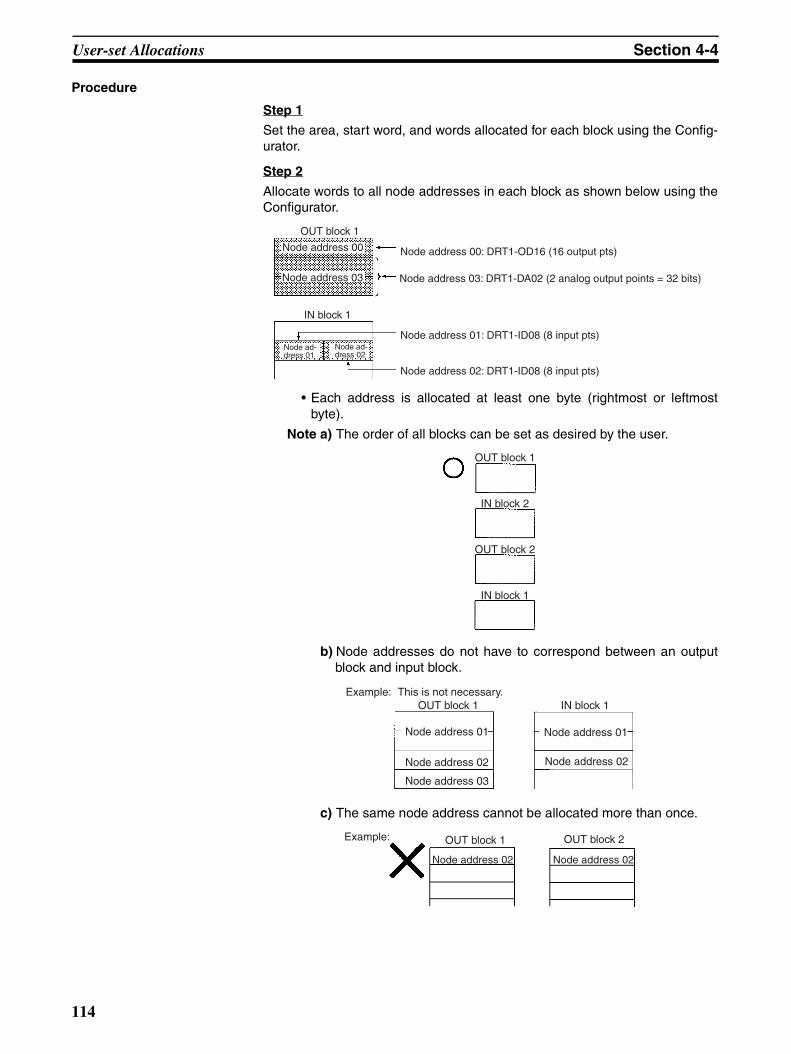
User-set Allocations Section 4-4
Procedure
Step 1
Set the area, start word, and words allocated for each block using the Config-urator.
Step 2
Allocate words to all node addresses in each block as shown below using theConfigurator.
• Each address is allocated at least one byte (rightmost or leftmostbyte).
Note a) The order of all blocks can be set as desired by the user.
b) Node addresses do not have to correspond between an outputblock and input block.
c) The same node address cannot be allocated more than once.
OUT block 1
Node address 00
Node address 03
Node address 00: DRT1-OD16 (16 output pts)
Node address 03: DRT1-DA02 (2 analog output points = 32 bits)
IN block 1
Node ad-dress 02
Node address 01: DRT1-ID08 (8 input pts)
Node address 02: DRT1-ID08 (8 input pts)
Node ad-dress 01
OUT block 1
IN block 2
OUT block 2
IN block 1
OUT block 1
Node address 01
Node address 02
Node address 03
IN block 1
Node address 01
Node address 02
This is not necessary.Example:
Example: OUT block 1
Node address 02
OUT block 2
Node address 02
114

User-set Allocations Section 4-4
d) The start bit for node addresses can be bit 00 or bit 08. If it is bit08 however, 2 or more bytes cannot be allocated as shown below.
e) Multiple masters cannot share the same slave.
You can determine whether there are duplicate node addresses in theI/O allocations (scan lists) that were created simply by conducting amaster parameter file duplicate check from the Configurator.
f) Be sure to use user-set allocations and operate with the scan listenabled if multiple masters are connected to a single network. ABus OFF errors will occur if multiple fixed allocations masters op-erating with the scan list disabled are present on a single network.
g) Multiple Master Units can be included in a single PLC as shownbelow using user-set allocations (16 Units max.).
Note Use Configurator Ver. 2.10 or later for the CJ1W-DRM21.
Example of User-set Allocations Using the Configurator
Start byte
Master
Slave
Master
Master Unit
Slave
Master Unit
Slave
Slave types
16 output ptsCombination of 8 input and output pts
Combination of 16 input and output pts
8 input pts
32 output pts
Slave types
48 input pts
8 input pts
Combination of 8 output and 16 input pts
Node address setting
Node address setting
Allocation status
Node address Output Input
Output Input
OUT area
OUT block 1 IN block 1
Allocation (00)
Allocation (01) Not used
Allocation (02)
Allocation (01) Allocation (03)
IN block 2
Allocation (02)
Allocation
Allocation
OUT block 2
Not used Allocation
Allocation
Allocation
Not used
Allocation (12)
Not used Allocation (09)
16 pts
8 pts
16 pts
0 pts
32 pts
0 pts
0 pts
8 pts
0 pts
8 pts
16 pts
8 pts
0 pts
8 pts
16 pts
48 pts
(10)
Allocation (12)
15
15 00
00
CIO 1950
CIO 1951
CIO 1952
CIO 1953
CIO 1954
01000
IN area
(04)
15
15 00
00
CIO 1900
CIO 1901
10 wd
11 wd
13 wd
12 wd
14 wd
15 wd
Node address
00
01
02
03
10
09
12
04
00
01
02
03
10
09
12
04
115
Starting and Stopping Remote I/O Communications Section 4-5
Configurator Setting Methods
Refer to the DeviceNet Configurator Operation Manual (W382) for settingmethods.
4-5 Starting and Stopping Remote I/O Communications
4-5-1 Starting Remote I/O CommunicationsRemote I/O communications start automatically after the power is turned ONor the Unit is restarted.
The I/O Data Communications Flag (word n+12, bit 15) is turned ON whenremote I/O communications is started with at least one slave.
4-5-2 Stopping Remote I/O CommunicationsRemote I/O communications stop under the following user-controlled condi-tions. Message communications can still be performed when the remote I/Ocommunications stop.
Stop Communications With All Slaves
Remote I/O communications stop when the Remote I/O CommunicationsStop Switch (word n, bit 04) is turned ON.
Stop Communications With a Specified Slave
Remote I/O communications stop when the Disconnect/Connect Switch forthe desired slave (words n+6 to n+9) is turned ON. (Units are disconnectedfrom remote I/O communication when the Disconnect/Connect Switch isturned ON.)
Note The communications cycle time is not shorter even though a slave has beendisconnected from remote I/O communications by turning ON the Disconnect/Connect Switch. (Blank time in the communications cycle will only beincreased.)
4-5-3 Restarting Remote I/O CommunicationsRemote I/O communications restart under the following conditions,
Restart Communications with All Slaves
Remote I/O communications restart when the Remote I/O CommunicationsStart Switch (word n, bit 01 or 03) is turned ON. (Only communications withslaves stopped using the Disconnect/Connect Switch will be restarted.)
Restart Communications with Specified Slave
Remote I/O communications restart when the Disconnect/Connect Switch forthe desired slave (words n+6 to n+9) is turned ON. Restoring the unit will havebeen completed when the Disconnect/Connect Switch turns OFF.)
4-6 Example of Ladder Programming for Remote I/O Communications
When writing ladder programming for remote I/O communications, make sureit performs I/O processing with a Slave under the following conditions:
• The I/O Data Communications Flag (word n+12, bit 15) is ON.
• The Unit Error Flag (word n+10, bit 00) is OFF.
Example: There is no jump and slave I/O is processed when the JMP(004)instruction input condition is ON in the following instructions. There is a jumpand slave I/O is not processed when the JMP(004) instruction input conditionis OFF.
116
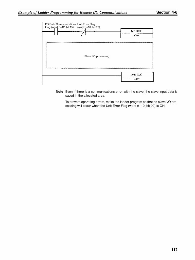
Example of Ladder Programming for Remote I/O Communications Section 4-6
Note Even if there is a communications error with the slave, the slave input data issaved in the allocated area.
To prevent operating errors, make the ladder program so that no slave I/O pro-cessing will occur when the Unit Error Flag (word n+10, bit 00) is ON.
I/O Data Communications Flag (word n+12, bit 15)
Unit Error Flag (word n+10, bit 00)
Slave I/O processing
117

Errors that May Occur in Remote I/O Communications Section 4-7
4-7 Errors that May Occur in Remote I/O CommunicationsThe following errors may occur during remote I/O communications.
Condition Error Details Results Indicators 7-segment display
Error occurs in fixed allo-cations with the scan list disabled
Structure Error Flag (word n+12, bit 04) turns ON
Duplicate I/O area
The same I/O word is allocated to two or more slaves. (This occurs whenever a slave that is allocated multiple words has one of the words allocated to the node address of another Slave.)
Reconnect with the error slave and continue remote I/O com-munications.
MS: Not relatedNS: Flashes red
d0
I/O area range exceeded
A slave is allocated an area out-side the fixed allocations area. (This occurs whenever slaves are allocated multiple words and a slave is allocated a word beyond node address 63 in the fixed allo-cations area.)
d1
Unsup-ported Slave
The I/O size of a slave exceeds 200 bytes (100 words). (This occurs if either the IN or the OUT size exceeds 200 bytes.)
d2
Error occurs in either fixed or user-set allocations with the scan list enabled
Verification Error Flag (word n+12, bit 00) turns ON
No slaves present
A Slave registered in the scan list is not present.
d5
I/O size mis-matched
The I/O size registered in the scan list does not match the I/O size of the slave.Note I/O size is compared in 8-
point (1-byte) units. If I/O size is registered at 8 points for example, then an error I/O size mismatch will not occur with a Slave with just one input point con-nected.
d6
Incorrect vendor
The vendor registered in the scan list does not match the slave ven-dor.
d6
Incorrect device type
The device type registered in the scan list does not match the slave device type.
d6
Incorrect product code
The product code registered in the scan list does not match the slave product code.
d6
Incorrect connection bus
The connection bus registered in the scan list is set incorrectly.
d6
Unsup-ported con-nection
The slave does not support the connection registered in the scan list.
d6
118
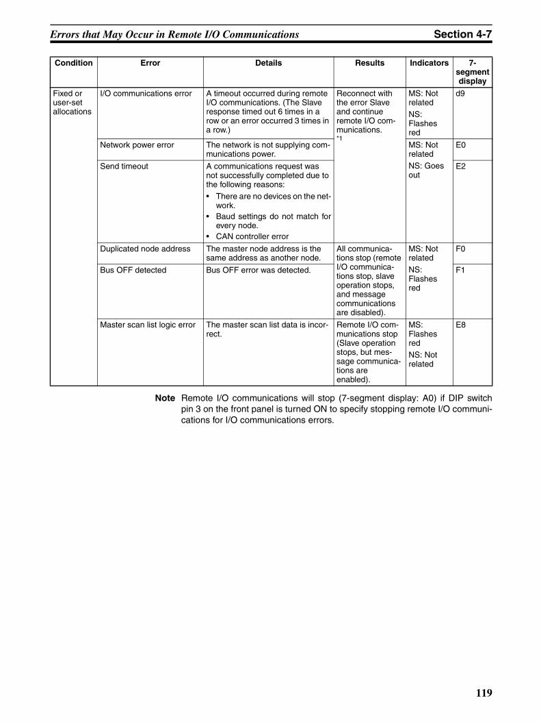
Errors that May Occur in Remote I/O Communications Section 4-7
Note Remote I/O communications will stop (7-segment display: A0) if DIP switchpin 3 on the front panel is turned ON to specify stopping remote I/O communi-cations for I/O communications errors.
Fixed or user-set allocations
I/O communications error A timeout occurred during remote I/O communications. (The Slave response timed out 6 times in a row or an error occurred 3 times in a row.)
Reconnect with the error Slave and continue remote I/O com-munications.*1
MS: Not relatedNS: Flashes red
d9
Network power error The network is not supplying com-munications power.
MS: Not relatedNS: Goes out
E0
Send timeout A communications request was not successfully completed due to the following reasons:• There are no devices on the net-
work.• Baud settings do not match for
every node.• CAN controller error
E2
Duplicated node address The master node address is the same address as another node.
All communica-tions stop (remote I/O communica-tions stop, slave operation stops, and message communications are disabled).
MS: Not relatedNS: Flashes red
F0
Bus OFF detected Bus OFF error was detected. F1
Master scan list logic error The master scan list data is incor-rect.
Remote I/O com-munications stop (Slave operation stops, but mes-sage communica-tions are enabled).
MS: Flashes redNS: Not related
E8
Condition Error Details Results Indicators 7-segment display
119


SECTION 5Remote I/O Slave Communications
This section describes the remote I/O communications performed as a DeviceNet slave by the DeviceNet Unit.
5-1 Slave Remote I/O Communications . . . . . . . . . . . . . . . . . . . . . . . . . . . . . . . . 122
5-1-1 Allocation Methods . . . . . . . . . . . . . . . . . . . . . . . . . . . . . . . . . . . . . 122
5-1-2 Remote I/O and Slave Communications Specifications . . . . . . . . . . 123
5-1-3 Procedures for Using Remote I/O Slave Communications . . . . . . . 123
5-2 Fixed Allocations . . . . . . . . . . . . . . . . . . . . . . . . . . . . . . . . . . . . . . . . . . . . . . 125
5-2-1 Allocated Words . . . . . . . . . . . . . . . . . . . . . . . . . . . . . . . . . . . . . . . . 125
5-2-2 Procedure . . . . . . . . . . . . . . . . . . . . . . . . . . . . . . . . . . . . . . . . . . . . . 125
5-3 User-set Allocations . . . . . . . . . . . . . . . . . . . . . . . . . . . . . . . . . . . . . . . . . . . . 126
5-3-1 Connection Types . . . . . . . . . . . . . . . . . . . . . . . . . . . . . . . . . . . . . . . 127
5-3-2 Procedure . . . . . . . . . . . . . . . . . . . . . . . . . . . . . . . . . . . . . . . . . . . . . 127
5-3-3 Connection Types . . . . . . . . . . . . . . . . . . . . . . . . . . . . . . . . . . . . . . . 130
121

Slave Remote I/O Communications Section 5-1
5-1 Slave Remote I/O CommunicationsA CS/CJ-series DeviceNet Unit can function as a Slave Unit in remote I/Ocommunications and a single CS/CJ-series DeviceNet Unit can function asboth a Master Unit and a Slave Unit. This section describes Slave communi-cations.
Slave Communications
Note 1. In the following descriptions, the areas used to transfer data from the mas-ter to the slaves are called OUT areas and the areas used to transfer datafrom the slaves to the master are called the IN areas.
2. In the following descriptions, a CS/CJ-series DeviceNet Unit set to functionas a master is referred to as a “Master Unit” and a CS/CJ-series DeviceNetUnit set to function as a slave is referred to as a “Slave Unit”.
5-1-1 Allocation MethodsAll slaves are allocated words in the I/O memory of the CPU Unit to which theMaster Unit is mounted. They are allocated using one of the following meth-ods:
1) Fixed allocations
2) User-set allocations
CS/CJ-series DeviceNet Unit (Master)CS/CJ-series CPU Unit IN area OUT area
IN area OUT area
Remote I/O communications
DeviceNet
CS/CJ-series CPU Unit
CS/CJ-series DeviceNet Unit (Slave)
Slaves
122
Slave Remote I/O Communications Section 5-1
5-1-2 Remote I/O and Slave Communications Specifications
5-1-3 Procedures for Using Remote I/O Slave CommunicationsFixed Allocations for Remote I/O
1,2,3... 1. Turn ON the communications, slave, and PLC power supplies.
Note Turn ON the communications power supply prior to turning ON theslave power supply or the slaves may not go online.
2. Switch the CPU Unit to PROGRAM mode.
3. Turn ON the Slave Stop Switch (word n+1, bit 07) from the PLC Program-ming Device to stop slave communications.
4. Turn ON one of the Slave Fixed Allocation Setting Switches (1 to 3: wordn+1, bits 08 to 10) from a Programming Device.
5. Turn ON the Slave Enable Switch (word n+1, bit 06) from a ProgrammingDevice to enable slave communications.
6. Switch the CPU Unit to RUN mode.
Slave remote I/O communications will start up.
Note Slave communications must be disabled prior to area allocation and must beenabled after area allocation. The order of the procedure is 1) stop slave com-
Item Specifications
Allocation method
Fixed allo-cations
Select one of the following fixed allocation areas using the Slave Fixed Allocated Area Switches 1, 2, and 3 in the software switches in the allocated CIO Area words.
Allocated words (CIO Area)
I/O Size Fixed Allo-cation Area
Setting 1
Fixed Allo-cation Area Setting 2
Fixed Allo-cation Area
Setting 3
Output (OUT) area to the slave from the master
1 word 3370 3570 3770
Input (OUT) area to the master from the slave
1 word 3270 3470 3670
Note Select one of the preceding areas using the software switches. All are fixed at 1 word per node address. The default setting is Fixed Allocation Area Setting 1.
User-set allocations
By allocated DM Area words
Set the areas, the first words, and slave allocation size for the OUT 1 and IN 1 blocks (total of 2 blocks) using the Slave User Allocation Setup Table in the allocated DM Area words.
Allocated words The input and output areas can be the following sizes starting from any word in any of the following areas: CIO Area, WR Area, HR Area, DM, Area, or EM Area.
Output (OUT) area from this slave 100 words
Input (IN) area to this slave 100 words
By Configurator Set the areas for the OUT 1 and IN 1/2 blocks, the first words, and the slave allocation sizes using the Configurator.
Allocated words The input and output areas can be the following sizes starting from any word in any of the following areas: CIO Area, WR Area, HR Area, DM, Area, or EM Area.
Output (OUT) area from this slave 100 words
Input (IN) area to this slave 100 words
Max. No. of I/O points per DeviceNet Unit slave
Fixed allocations 32 points (1 input word, 1 output word)
User-set allocations
By allocated DM Area words
3,200 pts (100 input words, 100 output words)
By Configurator 4,800 pts (100 input words x 2, 100 output words x 1)
123
Slave Remote I/O Communications Section 5-1
munications, allocate areas, and then enable slave communications. The allo-cated areas will not be valid if the procedure is done in any other order.
User-set Remote I/O Allocations Using DM Area Settings
1,2,3... 1. Turn ON the communications, slave, and PLC power supplies.
Note Turn ON the communications power supply prior to turning ON theslave power supply or the slaves may not go online.
2. Switch the CPU Unit to PROGRAM mode.
3. Turn ON the Slave Stop Switch (word n+1, bit 07) from the PLC Program-ming Device to stop slave communications.
4. Allocate areas as follows:
a) Set the Slave User Allocation Setup Table (m+8 to m+13 words) andthe Allocation Size Setup Table in the allocated DM Area words from aProgramming Device.
b) Turn ON the Slave User Allocations Switch (word n+1, bit 11) from aProgramming Device.
5. Turn ON the Slave Enable Switch (word n+1, bit 06) from a ProgrammingDevice to enable slave communications.
6. Switch the CPU Unit to RUN mode.
Slave remote I/O communications will start up.
Note 1. Slave communications must be disabled prior to area allocation and mustbe enabled after area allocation. The order of the procedure is 1) stopslave communications, allocate areas, and then enable slave communica-tions. The allocated areas will not be valid if the procedure is done in anyother order.
2. In fixed allocation or user-set allocations through the allocated DM Areasettings, area allocations must be set with slave communications disabledand will be transferred to Units when slave communications are enabled.
User-set Remote I/O Allocations Using the Configurator
1,2,3... 1. Connect the Configurator to the network through a serial line or dedicatedBoard/Card.
2. Turn ON the communications, slave, and PLC power supplies.
Note Turn ON the communications power supply prior to turning ON theslave power supply or the slaves may not go online.
3. Switch the CPU Unit to PROGRAM mode.
4. Perform the following steps to allocate areas, create scan lists, and down-load the settings to the nodes.
a) Enable slave communications in CS1W-DRM21(-V1) or CJ1W-DRM21 properties using the Configurator.
b) Create the device parameters to set slave communications.
c) Save the data as a device parameter file.
Note If desired, you can also go directly online and download the deviceparameter file to the DeviceNet Unit slave without saving the file.
d) Read the device parameter file, go online, and download the file to theDeviceNet Unit slave.
5. Switch the CPU Unit to RUN mode.
Slave remote I/O communications will start up.
124
Fixed Allocations Section 5-2
Note 1. Enable slave communications in CS1W-DRM21(-V1) or CJ1W-DRM21properties if the Configurator is used.
2. Use Configurator Ver. 2.10 or later for the CJ1W-DRM21.
5-2 Fixed Allocations
5-2-1 Allocated WordsWords in the CS/CJ-series DeviceNet CIO Area in the CPU Unit are allocated.Words can be selected from one of three fixed allocation areas. Use a Soft-ware Switch to select the allocation area.
Each area is comprised of an OUT area that is used to write data to the mas-ter IN area and an IN area that is used for inputs from the master OUT area inremote I/O communications.
A maximum of 3 DeviceNet Units can be included as slaves in a single PLCbecause the three allocation areas above are set individually for fixed alloca-tions. The default setting is fixed allocations area 1.
5-2-2 ProcedureStep 1: Stop Slave Communications
If the Unit is already functioning as a Slave Unit, turn ON the Slave StopSwitch (word n+1, bit 07) to stop slave communications. This step is not nec-essary if slave communications have already stopped.
Step 2: Select a Fixed Allocation Area
Turn ON one of the Slave Fixed Allocation Setting Switches (1 to 3: word n+1,bits 08 to 10) in the allocated CIO Area words to select a fixed allocation areabetween 1 and 3. One words is allocated for the output (OUT) area from theSlave Unit to the master and another word is allocated for the input (IN) areafrom the master to the Slave Unit in the CS/CJ-series DeviceNet CIO Area, asshown below.
First word n = CIO 1500 + (25 x unit number)
Step 3: Turn ON the Slave Enable Switch
Turn ON the Slave Enable Switch (word n+1, bit 06). This will allocated thefixed allocation areas as slave areas and the DeviceNet Unit will start slaveremote I/O communications. Slave communications will run automaticallyafter that whenever the power is turned ON.
Area OUT area (master to slave)
IN area (slave to master)
Selection method
Fixed allocation area 1 CIO 3370 CIO 3270 Turn ON the Slave Fixed Allocation Set-ting 1 Switch (word n, bit 08).
Fixed allocation area 2 CIO 3570 CIO 3470 Turn ON the Slave Fixed Allocation Set-ting 2 Switch (word n, bit 09).
Fixed allocation area 3 CIO 3770 CIO 3670 Turn ON the Slave Fixed Allocation Set-ting 3 Switch (word n, bit 010).
Software switch address
Software switch name Fixed allocation area Allocated output (OUT) area
(master to slave)
Allocated input (IN) area
(slave to master)
Word n+1, bit 08 Slave Fixed Allocation Setting 1 Switch
Fixed allocation area 1 CIO 3370 CIO 3270
Word n+1, bit 09 Slave Fixed Allocation Setting 2 Switch
Fixed allocation area 2 CIO 3570 CIO 3470
Word n+1, bit 10 Slave Fixed Allocation Setting 3 Switch
Fixed allocation area 3 CIO 3770 CIO 3670
125
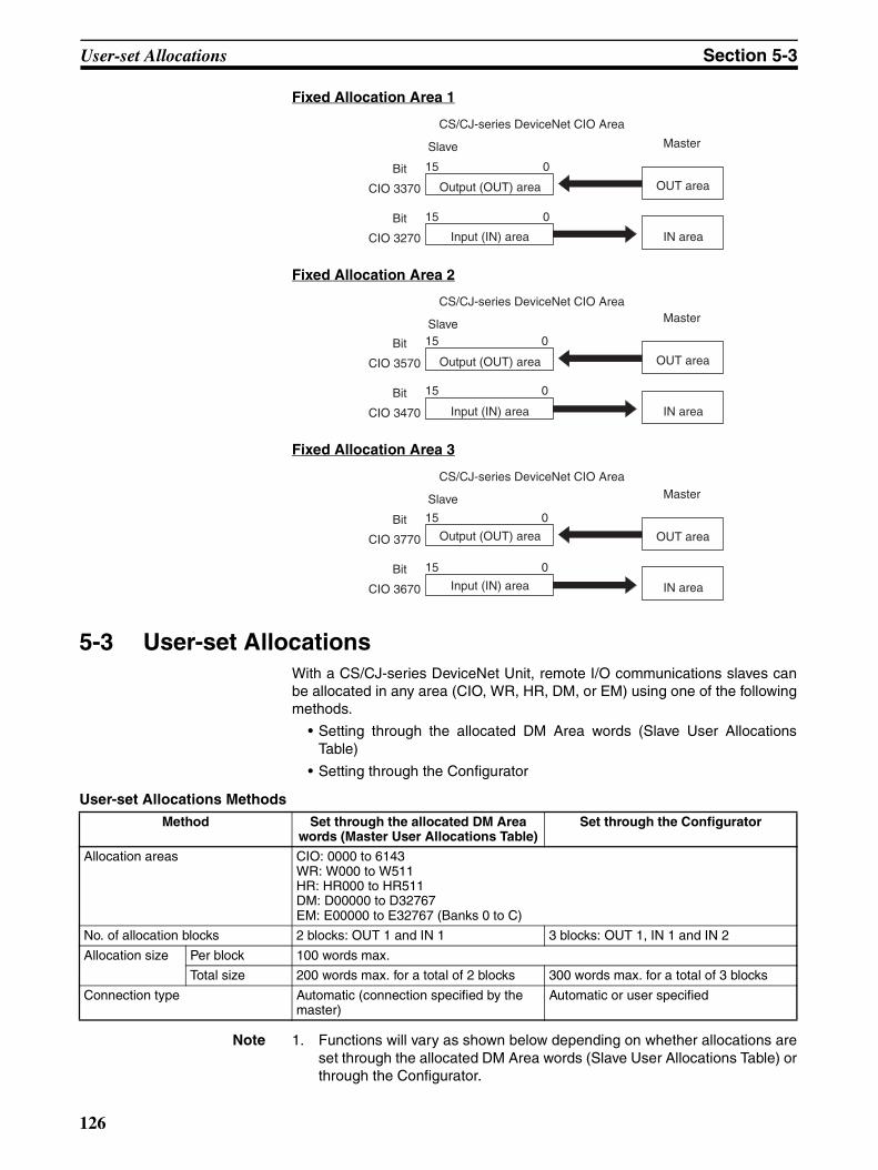
User-set Allocations Section 5-3
Fixed Allocation Area 1
Fixed Allocation Area 2
Fixed Allocation Area 3
5-3 User-set AllocationsWith a CS/CJ-series DeviceNet Unit, remote I/O communications slaves canbe allocated in any area (CIO, WR, HR, DM, or EM) using one of the followingmethods.
• Setting through the allocated DM Area words (Slave User AllocationsTable)
• Setting through the Configurator
User-set Allocations Methods
Note 1. Functions will vary as shown below depending on whether allocations areset through the allocated DM Area words (Slave User Allocations Table) orthrough the Configurator.
CS/CJ-series DeviceNet CIO Area
Slave
Bit
Output (OUT) area
Input (IN) area
Master
OUT area
IN area
015
CIO 3370
Bit 015
CIO 3270
CS/CJ-series DeviceNet CIO Area
Slave
Bit
Output (OUT) area
Input (IN) area
Master
OUT area
IN area
015
CIO 3570
Bit 015
CIO 3470
CS/CJ-series DeviceNet CIO Area
Slave
BitOutput (OUT) area
Input (IN) area
Master
OUT area
IN area
015
CIO 3770
Bit 015
CIO 3670
Method Set through the allocated DM Area words (Master User Allocations Table)
Set through the Configurator
Allocation areas CIO: 0000 to 6143WR: W000 to W511HR: HR000 to HR511DM: D00000 to D32767EM: E00000 to E32767 (Banks 0 to C)
No. of allocation blocks 2 blocks: OUT 1 and IN 1 3 blocks: OUT 1, IN 1 and IN 2
Allocation size Per block 100 words max.
Total size 200 words max. for a total of 2 blocks 300 words max. for a total of 3 blocks
Connection type Automatic (connection specified by the master)
Automatic or user specified
126
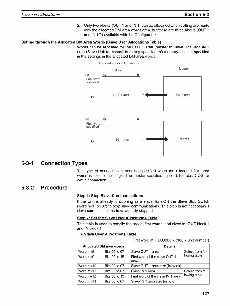
User-set Allocations Section 5-3
2. Only two blocks (OUT 1 and IN 1) can be allocated when setting are madewith the allocated DM Area words area, but there are three blocks (OUT 1and IN 1/2) available with the Configurator.
Setting through the Allocated DM Area Words (Slave User Allocations Table)Words can be allocated for the OUT 1 area (master to Slave Unit) and IN 1area (Slave Unit to master) from any specified I/O memory location specifiedin the settings in the allocated DM area words.
5-3-1 Connection TypesThe type of connection cannot be specified when the allocated DM areawords is used for settings. The master specifies a poll, bit-strobe, COS, orcyclic connection.
5-3-2 ProcedureStep 1: Stop Slave Communications
If the Unit is already functioning as a slave, turn ON the Slave Stop Switch(word n+1, bit 07) to stop slave communications. This step is not necessary ifslave communications have already stopped.
Step 2: Set the Slave User Allocations Table
This table is used to specify the areas, first words, and sizes for OUT block 1and IN block 1.
• Slave User Allocations Table
First word m = D30000 + (100 x unit number)
Specified area in I/O memory
SlaveBitFirst word specified
OUT 1 area OUT area
Master
IN areaIN 1 area
15 0
to
BitFirst word specified
15 0
to
Allocated DM area words Details
Word m+8 Bits 00 to 07 Slave OUT 1 area Select from fol-lowing tableWord m+9 Bits 00 to 15 First word of the slave OUT 1
area
Word m+10 Bits 00 to 07 Slave OUT 1 area size (in bytes)
Word m+11 Bits 00 to 07 Slave IN 1 area Select from fol-lowing tableWord m+12 Bits 00 to 15 First word of the slave IN 1 area
Word m+13 Bits 00 to 07 Slave IN 1 area size (in byte)
127
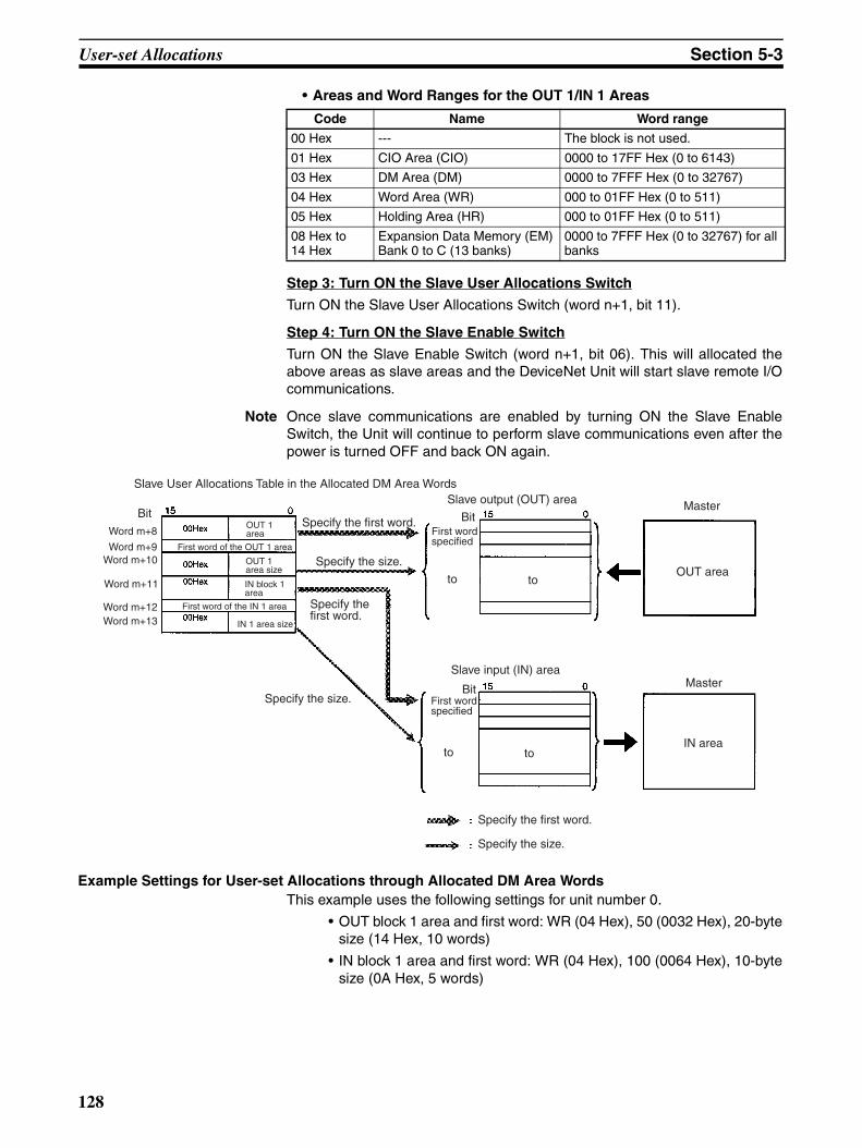
User-set Allocations Section 5-3
• Areas and Word Ranges for the OUT 1/IN 1 Areas
Step 3: Turn ON the Slave User Allocations Switch
Turn ON the Slave User Allocations Switch (word n+1, bit 11).
Step 4: Turn ON the Slave Enable Switch
Turn ON the Slave Enable Switch (word n+1, bit 06). This will allocated theabove areas as slave areas and the DeviceNet Unit will start slave remote I/Ocommunications.
Note Once slave communications are enabled by turning ON the Slave EnableSwitch, the Unit will continue to perform slave communications even after thepower is turned OFF and back ON again.
Example Settings for User-set Allocations through Allocated DM Area WordsThis example uses the following settings for unit number 0.
• OUT block 1 area and first word: WR (04 Hex), 50 (0032 Hex), 20-bytesize (14 Hex, 10 words)
• IN block 1 area and first word: WR (04 Hex), 100 (0064 Hex), 10-bytesize (0A Hex, 5 words)
Code Name Word range
00 Hex --- The block is not used.
01 Hex CIO Area (CIO) 0000 to 17FF Hex (0 to 6143)
03 Hex DM Area (DM) 0000 to 7FFF Hex (0 to 32767)
04 Hex Word Area (WR) 000 to 01FF Hex (0 to 511)
05 Hex Holding Area (HR) 000 to 01FF Hex (0 to 511)
08 Hex to 14 Hex
Expansion Data Memory (EM)Bank 0 to C (13 banks)
0000 to 7FFF Hex (0 to 32767) for all banks
Slave User Allocations Table in the Allocated DM Area Words
BitOUT 1 area
First word of the OUT 1 area
OUT 1 area size
IN block 1 area
First word of the IN 1 area
IN 1 area size
Specify the first word.
Specify the size.
Specify the first word.
Specify the size.
Slave output (OUT) area Master
OUT area
BitFirst word specified
Slave input (IN) area
BitFirst word specified
Master
IN area
Specify the first word.
Specify the size.
toto
toto
Word m+8
Word m+9Word m+10
Word m+11
Word m+12Word m+13
128
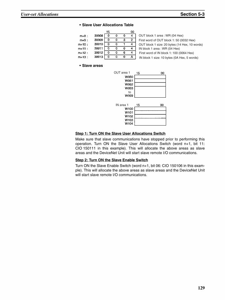
User-set Allocations Section 5-3
• Slave User Allocations Table
• Slave areas
Step 1: Turn ON the Slave User Allocations Switch
Make sure that slave communications have stopped prior to performing thisoperation. Turn ON the Slave User Allocations Switch (word n+1, bit 11:CIO 150111 in this example). This will allocate the above areas as slaveareas and the DeviceNet Unit will start slave remote I/O communications.
Step 2: Turn ON the Slave Enable Switch
Turn ON the Slave Enable Switch (word n+1, bit 06: CIO 150106 in this exam-ple). This will allocate the above areas as slave areas and the DeviceNet Unitwill start slave remote I/O communications.
OUT block 1 area : WR (04 Hex)
First word of OUT block 1: 50 (0032 Hex)OUT block 1 size: 20 bytes (14 Hex, 10 words)IN block 1 area : WR (04 Hex)First word of IN block 1: 100 (0064 Hex)
IN block 1 size: 10 bytes (0A Hex, 5 words)
OUT area 1
IN area 1
to
129

User-set Allocations Section 5-3
Setting through the Configuration
A maximum of three blocks can be allocated at any locations in I/O memoryfor the output (OUT) area block 1, input (IN) area block 1, and input (IN) areablock 2.
The block allocation order and block allocation areas can be set as required.Refer to the DeviceNet Configurator Operation Manual (W382) for details onthe allocation procedure.
5-3-3 Connection TypesThe type of connection can be specified if the Configurator is used for set-tings. The number of applicable allocation areas varies with the type of con-nection used.
• A maximum of three areas (OUT 1, IN 1, and IN 2) can be used whenmultiple connections are specified.
• Two allocation areas (OUT 1 and IN 1) can be used if the automatic con-nection setting or a single connection is specified.
Specified area in I/O memory
User-set block order Master
Slave output (OUT) area 1 OUT area
Slave input (IN) area 1 IN area
BitFirst word specified
15 0
to
BitFirst word specified
15 0
to
Slave input (IN) area 2 IN area
BitFirst word specified
15 0
to
130
User-set Allocations Section 5-3
Connection Types and Allocated I/O Areas
The following table shows the relationship between various connection combi-nations and the allocated areas that are applicable with those connections.
Note 1. With poll + COS connections, the OUT data is the same for poll and COS.Set the same OUT areas for poll and COS connections when specifyingthe areas with the Configurator. With poll + cyclic connections as well, theOUT data is the same for poll and cyclic. Set the same OUT areas for polland cyclic when specifying the areas with the Configurator.
2. Use Configurator Ver. 2.10 or later for the CJ1W-DRM21.
Specified connection type
OUT 1 area IN 1 area IN 2 area
Poll Poll OUT data Poll IN data Not used
Bit-strobe Not used Bit-strobe IN data Not used
COS COS OUT data COS IN data Not used
Cyclic Cyclic OUT data Cyclic IN data Not used
Poll+bit-strobe Poll OUT data Poll IN data Bit-strobe IN data
Poll+COS (See note.) Poll/COS OUT data Poll IN data COS IN data
Poll+cyclic (See note.) Poll/cyclic OUT data Poll IN data Cyclic IN data
COS+bit-strobe COS OUT data COS IN data Bit-strobe IN data
Cyclic+bit-strobe Cyclic OUT data Cyclic IN data Bit-strobe IN data
131

SECTION 6Message Communications
This section describes message communications using FINS commands sent from the ladder program in the CPU Unit ofthe PLC.
6-1 Overview . . . . . . . . . . . . . . . . . . . . . . . . . . . . . . . . . . . . . . . . . . . . . . . . . . . . . 134
6-1-1 Outline of Message Communications. . . . . . . . . . . . . . . . . . . . . . . . 134
6-1-2 FINS Message Communications . . . . . . . . . . . . . . . . . . . . . . . . . . . 135
6-1-3 Explicit Message Communications . . . . . . . . . . . . . . . . . . . . . . . . . 137
6-1-4 Message Communications Specifications . . . . . . . . . . . . . . . . . . . . 138
6-1-5 Message Communications Error Indications . . . . . . . . . . . . . . . . . . 139
6-1-6 Message Monitoring Timer . . . . . . . . . . . . . . . . . . . . . . . . . . . . . . . 140
6-1-7 Message Communications Errors . . . . . . . . . . . . . . . . . . . . . . . . . . . 140
6-2 FINS Commands and Responses . . . . . . . . . . . . . . . . . . . . . . . . . . . . . . . . . . 141
6-2-1 FINS Communications . . . . . . . . . . . . . . . . . . . . . . . . . . . . . . . . . . . 141
6-2-2 Sending/Receiving FINS Command/Responses. . . . . . . . . . . . . . . . 142
6-2-3 Units Supporting FINS Communications. . . . . . . . . . . . . . . . . . . . . 143
6-2-4 FINS Command Lists . . . . . . . . . . . . . . . . . . . . . . . . . . . . . . . . . . . . 143
6-3 Using FINS Message Communications . . . . . . . . . . . . . . . . . . . . . . . . . . . . . 145
6-3-1 Setting Node Addresses . . . . . . . . . . . . . . . . . . . . . . . . . . . . . . . . . . 145
6-3-2 Creating Routing Tables . . . . . . . . . . . . . . . . . . . . . . . . . . . . . . . . . . 145
6-3-3 Data Send/Receive Instructions . . . . . . . . . . . . . . . . . . . . . . . . . . . . 148
6-3-4 Sending FINS Commands . . . . . . . . . . . . . . . . . . . . . . . . . . . . . . . . 150
6-3-5 Using SEND(090), RECV(098), and CMND(490) . . . . . . . . . . . . . 151
6-3-6 Connecting Networks for FINS Communications . . . . . . . . . . . . . . 156
6-4 Sending Explicit Messages . . . . . . . . . . . . . . . . . . . . . . . . . . . . . . . . . . . . . . . 157
6-4-1 Sending Explicit Messages . . . . . . . . . . . . . . . . . . . . . . . . . . . . . . . . 158
6-4-2 Sending Explicit Messages Using CMND(490). . . . . . . . . . . . . . . . 160
6-5 Receiving Explicit Messages . . . . . . . . . . . . . . . . . . . . . . . . . . . . . . . . . . . . . 164
6-5-1 List of PLC Object Services . . . . . . . . . . . . . . . . . . . . . . . . . . . . . . . 165
133

Overview Section 6-1
6-1 OverviewMessage communications enable messages to be set between nodes on aDeviceNet network when required by system conditions. The messages canbe sent between PLCs, between an OMRON PLC and a master made byanother company, or between slaves. They can be used to send/receive data;read time data, error histories, and other data; or control operation, e.g., byforce-setting/resetting bits.
There are two types of messages: FINS messages and explicit messages.
6-1-1 Outline of Message CommunicationsItem FINS messages Explicit messages
Outline Message communications for OMRON products that use the FINS protocol.
General-purpose message com-munications using the DeviceNet protocol.
Remote device
OMRON PLCs (with a CS/CJ-series DeviceNet Unit)
Other manufacturer masters or slaves.OMRON PLCs with C200H or CVM1/CV-series DeviceNet Mas-ter Unit or CS/CJ-series DeviceNet UnitsOMRON PLCs with C200H I/O Link Units
Features Provide a greater range of services than explicit messages by sending and receiving FINS commands.Have message compatibility with other OMRON networks, such as Controller Link, SYSMAC LINK, and Ethernet (up to 3 levels)
Enable message communications with DeviceNet devices from other manufacturers.Can receive explicit messages from OMRON PLCs with C200H- or CVM1/CV-series DeviceNet Master Units and can send explicit messages to OMRON PLCs with C200H I/O Link Units
Message communications functions
FINS communications function
Explicit message communications function
Send
Receive
Send
Receive
134
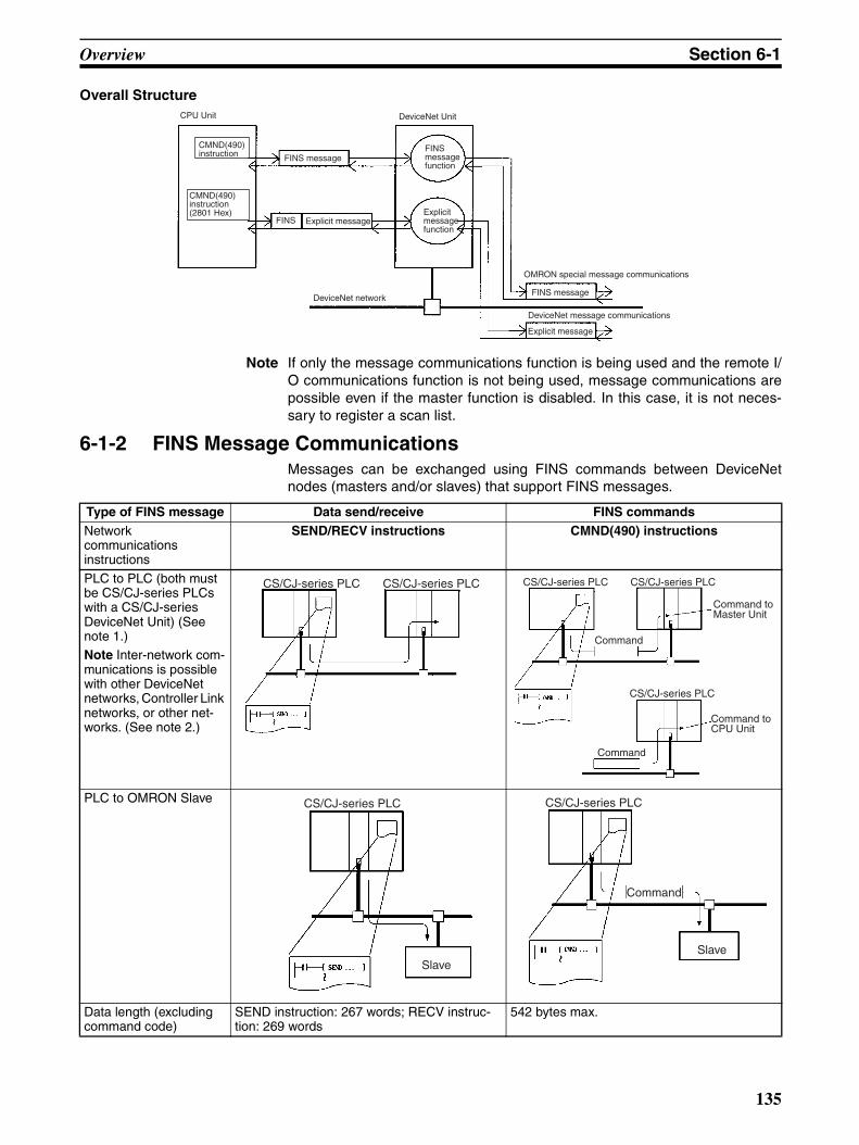
Overview Section 6-1
Overall Structure
Note If only the message communications function is being used and the remote I/O communications function is not being used, message communications arepossible even if the master function is disabled. In this case, it is not neces-sary to register a scan list.
6-1-2 FINS Message CommunicationsMessages can be exchanged using FINS commands between DeviceNetnodes (masters and/or slaves) that support FINS messages.
CPU Unit
CMND(490) instruction
DeviceNet Unit
CMND(490) instruction(2801 Hex)
FINS message
FINS Explicit message
FINS message function
Explicit message function
DeviceNet networkFINS message
Explicit message
OMRON special message communications
DeviceNet message communications
Type of FINS message Data send/receive FINS commandsNetwork communications instructions
SEND/RECV instructions CMND(490) instructions
PLC to PLC (both must be CS/CJ-series PLCs with a CS/CJ-series DeviceNet Unit) (See note 1.)Note Inter-network com-munications is possible with other DeviceNet networks, Controller Link networks, or other net-works. (See note 2.)
PLC to OMRON Slave
Data length (excluding command code)
SEND instruction: 267 words; RECV instruc-tion: 269 words
542 bytes max.
CS/CJ-series PLC CS/CJ-series PLC CS/CJ-series PLC CS/CJ-series PLC
Command
CS/CJ-series PLC
Command
Command to Master Unit
Command to CPU Unit
CS/CJ-series PLC
Slave
CS/CJ-series PLC
Command
Slave
135

Overview Section 6-1
Note 1. The DeviceNet Unit must be registered in the local network routing table ofthe CS/CJ-series PLC when two or more Communications Units (includingthe DeviceNet Unit) are mounted to a CS/CJ-series PLC. The commandswill not be sent if the Unit is not registered in the routing tables.
2. For DeviceNet networks connected to a CS/CJ-series DeviceNet Unit,message communications can be conducted between networks, includingother DeviceNet networks as well as Controller Link, SYSMAC LINK, andEthernet networks. Up to three levels of networks can be crossed. Routingtables (containing local network tables and relay network tables) must beregistered in the CPU Units of each PLC on the network.
Note FINS commands sent and received by the CS/CJ-series DeviceNetUnit include commands addressed to the CS/CJ-series CPU Unitand commands addressed to the CS/CJ-series DeviceNet Unit.
FINS message communications is possible between two PLCs with CS1W-DRM21(-V1) or CJ1W-DRM21 DeviceNet Units.
FINS messages cannot be sent or received for PLCs with C200H-seriesDeviceNet Master Units (C200HW-DRM21-V1) or CVM1/CV-seriesDeviceNet Master Units (CVM1-DRM21-V1). Explicit messages, however,can be received from these PLCs.
The following table outlines which CPU Unit support for FINS message com-munications.
Up to 3 network levels, including DeviceNet, can be crossed.
Controller Link UnitController Link Unit
CS/CJ-series DeviceNet UnitCS/CJ-series CPU Unit
Remote I/O communications
Controller Link
DeviceNet
CS/CJ-series DeviceNet UnitDeviceNet
CS/CJ-series DeviceNet Unit
CPU Unit sending message
Mounted DeviceNet
Unit/ DeviceNet
Master Unit
FINS message CPU Unit in receiving message
CS Series
CJ Series CS Series
C200HX/HG/HE
CVM1/CV Series
Instructions to send/
receive data
Instructions to execute any FINS command
CS1W- DRM21
(-V1)
CJ1W-DRM21
C200HW- DRM21-
V1
C200HW- DRM21-
V1
CVM1- DRM21-
V1
CS Series CS1W- DRM211(-V1)
SEND/RECV CMND Can receive Cannot receive
Cannot receive
Cannot receive
CJ Series CJ1W-DRM21
CS Series C200HW- DRM21-V1
Not supported IOWR Cannot receive Can receive
Can receive
Can receive
C200HX/HG/HE
C200HW- DRM21-V1
Not supported IOWR Cannot receive Can receive
Can receive
Can receive
CVM1/CV Series
CVM1- DRM21-V1
SEND/RECV CMND Cannot receive Can receive
Can receive
Can receive
136
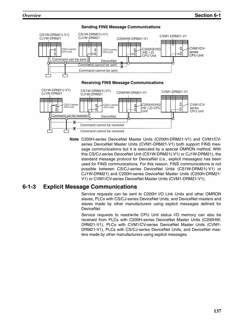
Overview Section 6-1
Sending FINS Message Communications
Receiving FINS Message Communications
Note C200H-series DeviceNet Master Units (C200H-DRM21-V1) and CVM1/CV-series DeviceNet Master Units (CVM1-DRM21-V1) both support FINS mes-sage communications but it is executed by a special OMRON method. Withthis CS/CJ-series DeviceNet Unit (CS1W-DRM21(-V1) or CJ1W-DRM21), thestandard message protocol for DeviceNet (i.e., explicit messages) has beenused for FINS communications. For this reason, FINS communications is notpossible between CS/CJ-series DeviceNet Units (CS1W-DRM21(-V1) orCJ1W-DRM21) and C200H-series DeviceNet Master Units (C200H-DRM21-V1) or CVM1/CV-series DeviceNet Master Units (CVM1-DRM21-V1).
6-1-3 Explicit Message CommunicationsService requests can be sent to C200H I/O Link Units and other OMRONslaves, PLCs with CS/CJ-series DeviceNet Units, and DeviceNet masters andslaves made by other manufacturers using explicit messages defined forDeviceNet.
Service requests to read/write CPU Unit status I/O memory can also bereceived from PLCs with C200H-series DeviceNet Master Units (C200HW-DRM21-V1), PLCs with CVM1/CV-series DeviceNet Master Units (CVM1-DRM21-V1), PLCs with CS/CJ-series DeviceNet Units, and DeviceNet mas-ters made by other manufacturers using explicit messages.
CS1W-DRM21(-V1)CJ1W-DRM21 C200HW-DRM21-V1
CVM1-DRM21-V1
Command can be sent.
Command cannot be sent.
Command cannot be sent.
DeviceNet
C200HX/HG/HE (-Z) CPU Unit
CVM1/CV-series CPU Unit
XX
CS1W-DRM21(-V1)CJ1W-DRM21
CS/CJ-seriesCPU Unit
CS/CJ-seriesCPU Unit
CS1W-DRM21(-V1)CJ1W-DRM21 C200HW-DRM21-V1 CVM1-DRM21-V1
CS/CJ-series CPU Unit
Command can be received
Command cannot be received
Command cannot be received
DeviceNet
C200HX/HG/HE (-Z) CPU Unit
CVM1/CV-series CPU Unit
X
X
CS1W-DRM21(-V1)CJ1W-DRM21
CS/CJ-series CPU Unit
137
Overview Section 6-1
Note A specific FINS command (command 2801) is used to send explicit mes-sages.
Note A specific FINS command (command 2801) is used to send explicitmessages.
Note This CS/CJ-series DeviceNet Unit (CS1W-DRM21(-V1) or CJ1W-DRM21)contains a PLC Object so that the I/O memory of the CPU Unit of theDeviceNet Unit can be read/written from other devices. The C200HW-DRT21I/O Link Unit also contains a PLC Object so that the I/O memory of the CPUUnit of the I/O Link Unit can be read/written from other devices. The C200HW-DRM21-V1 and CVM1-DRM21-V1 DeviceNet Master Units, however, do nothave PLC Objects, the I/O memory of the CPU Unit for these Units cannot beread or written from other devices.
6-1-4 Message Communications Specifications
Item Sending Receiving
Network commu-nications instruc-tion
CMND(490) using FINS command code 2801 Hex can be used to send explicit messages to DeviceNet devices. (See note.)
Automatically responds to explicit messages from other devices.
Remote devices and supported functions
Masters/slaves made by other manufacturers. Sup-ported services determine supported functions.PLCs with CS/CJ-series DeviceNet Units mounted. Remote CPU Unit status read/write and I/O memory read/write functions supported.PLCs with C200H I/O Link Units mounted. Remote CPU Unit I/O memory read/write function sup-ported.
Masters made by other manufacturers.PLCs with CS/CJ-series DeviceNet Units.PLCs with C200H-series DeviceNet Master Units.PLCs with CVM1/CV-series DeviceNet Master Units.
All listed devices support status read/write and I/O memory read/write for the local CPU Unit.
Item Specification
Applicable PLC CS/CJ-series
Unit model number CS1W-DRM21(-V1)/CJ1W-DRM21
Max. No. of communica-tions nodes per Unit
FINS mes-sages
62 (node address 0 cannot be used for FINS communications)
Explicit mes-sages
63
Communications instruc-tions
Sending/ receiving data
SEND and RECV instructions
FINS com-mands
CMND(490) instruction
There are FINS commands addressed to the PLC and others addressed to the CS/CJ-series DeviceNet Unit.Note FINS commands can be sent to PLCs with CS/CJ-series DeviceNet Units mounted to them. FINS commands cannot be sent to PLCs with C200HW-DRM21-V1 or CVM1-DRM21-V1 DeviceNet Master Units mounted to them.
Explicit DeviceNet messages
CMND(490) instruction
Sends explicit messages to masters/slaves made by other manufacturers, PLCs with C200H I/O Link Units, or PLCs with CS/CJ-series DeviceNet Units mounted to them.
Sources:destinations 1:1 (Broadcasting is not supported)
Data length (excluding command code) SEND: 267 words max.RECV: 269 words max.CMND 542 bytes max.
138
Overview Section 6-1
6-1-5 Message Communications Error IndicationsThere are two ways to obtain information on communications errors that occurin message communications: 1) Using the error history in the DeviceNet Unitand 2) Using DeviceNet Unit displays, indicators, and Master Status Areas.
1,2,3... 1. Each time a communications error occurs, an error code is placed in an er-ror record in the error history kept in the RAM of the DeviceNet Unit. Up to64 records can be stored in the error history. The time and data the recordoccurred is also recorded.
The error history can be read or cleared from the CPU Unit by sending anFINS command to the DeviceNet Unit (Error History Read/Clear). The con-tents of the error history can also be monitored from the Configurator.
2. The MS and NS indicators and the 7-segment display on the front panel ofthe DeviceNet Unit can be used together with the Master Status Area 1 inthe CPU Unit to obtain information on a communications error that has oc-curred. This information can be used as the basis for troubleshooting.
No. of simultaneous instructions One each for 8 ports (ports 0 to 7)Refer to 3-25 Network Instructions in the CS/CJ Series Programmable Controllers Instructions Reference Manual (W340) for information on ports (logical ports).
Response monitoring time Default setting: 2 sUser setting: 0.1 to 6553.5 s
Retries 0 to 15
FINS mes-sage com-munications commands
Received from CS/CJ-series CPU Unit with CS/CJ-series DeviceNet Unit
Supported (Data send/receive or FINS commands).
Received from CVM1/CV-series CPU Units with CVM1/CV-series DeviceNet Master Unit
Not supported.
Received from CS/CJ-series and C200HX/HG/HE CPU Units with C200H-series DeviceNet Master Unit
Received from C200HX/HG/HE Units with C200H-series DeviceNet Master Unit
Internetwork connections Same net-work type
Supports internetwork communications between DeviceNet networks with CS/CJ-series DeviceNet Units mounted (up to 3 levels).
Different net-work type
Supports internetwork communications between DeviceNet networks with CS/CJ-series DeviceNet Units mounted and other networks (Controller Link, SYSMAC LINK, and Ethernet; up to 3 levels).
Message monitor timer function (explicit message communications)
The response monitoring time for DeviceNet Units during explicit message communications (the interval the explicit connection is open) can be set from the Configurator for each device. (The settings for all devices can be stored in the DeviceNet Unit. This is called the Message Monitoring Timer List.)
Item Specification
CPU Unit
Configurator
FINS commandRead-out
Monitor
CodeCode
Code
64 records
139

Overview Section 6-1
6-1-6 Message Monitoring TimerA message monitoring timer monitors responses for the DeviceNet Unit. Atimer can be set for each device that will be communicated with (each mes-sage destination).
Message monitoring timers are supported for both explicit message and FINSmessage communications. The timers can be set with version 2 or later of theDeviceNet Configurator. The default setting is 2 seconds (2,000 ms). The set-ting range is 500 to 30,000 ms.
If the response from the remote communications device (message destina-tion) is slow, the timer setting must be increased. In particular, responses taketime in FINS message communications that cross different network layers, sothis setting must be increased. The next message cannot be sent to the samecommunications device during the response waiting time, so the settingshould not be set too high.
The DeviceNet Unit uses this timer to monitor message timeouts. The CPUUnit performs the monitoring based on the response monitoring time forCMND, SEND(090), and RECV instructions. There will be no effect, therefore,if either the message monitoring timer or the response monitoring time forCMND/SEND/RECV instructions setting only is increased or decreased. Bothmust be increased or decreased for there to be an effect.
Set the response monitoring time for the CMND, SEND(090), and RECVinstructions the same as or longer than the message monitoring timer, i.e.,CMND, SEND(090), RECV instructions ≥ message monitoring timer.
If a lot of timeouts occur, maintain this relationship but lengthen the time forboth.
Note When performing remote programming or monitoring from the CX-Program-mer (scheduled to be supported by version 2.1 and later), set the messagemonitoring timer in the CS/CJ-series DeviceNet Unit mounted to the PLC con-nected to the CX-Programmer to at least 20 s (20,000 ms). This setting isrequired only for the Unit that will perform remote programming.
6-1-7 Message Communications ErrorsThe following table shows the main errors that occur when messages are sentor received. Refer to SECTION 9 Troubleshooting and Maintenance for coun-
Master Status Area 1
CPU Unit
Device-Net Unit
Example: Routing table error
Flashing redNot relevant
140
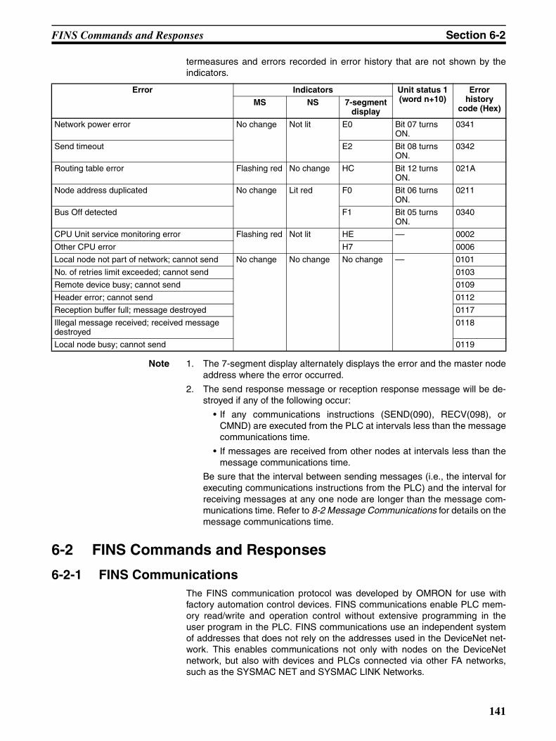
FINS Commands and Responses Section 6-2
termeasures and errors recorded in error history that are not shown by theindicators.
Note 1. The 7-segment display alternately displays the error and the master nodeaddress where the error occurred.
2. The send response message or reception response message will be de-stroyed if any of the following occur:
• If any communications instructions (SEND(090), RECV(098), orCMND) are executed from the PLC at intervals less than the messagecommunications time.
• If messages are received from other nodes at intervals less than themessage communications time.
Be sure that the interval between sending messages (i.e., the interval forexecuting communications instructions from the PLC) and the interval forreceiving messages at any one node are longer than the message com-munications time. Refer to 8-2 Message Communications for details on themessage communications time.
6-2 FINS Commands and Responses
6-2-1 FINS CommunicationsThe FINS communication protocol was developed by OMRON for use withfactory automation control devices. FINS communications enable PLC mem-ory read/write and operation control without extensive programming in theuser program in the PLC. FINS communications use an independent systemof addresses that does not rely on the addresses used in the DeviceNet net-work. This enables communications not only with nodes on the DeviceNetnetwork, but also with devices and PLCs connected via other FA networks,such as the SYSMAC NET and SYSMAC LINK Networks.
Error Indicators Unit status 1 (word n+10)
Error history
code (Hex)MS NS 7-segment
display
Network power error No change Not lit E0 Bit 07 turns ON.
0341
Send timeout E2 Bit 08 turns ON.
0342
Routing table error Flashing red No change HC Bit 12 turns ON.
021A
Node address duplicated No change Lit red F0 Bit 06 turns ON.
0211
Bus Off detected F1 Bit 05 turns ON.
0340
CPU Unit service monitoring error Flashing red Not lit HE –– 0002
Other CPU error H7 0006
Local node not part of network; cannot send No change No change No change –– 0101
No. of retries limit exceeded; cannot send 0103
Remote device busy; cannot send 0109
Header error; cannot send 0112
Reception buffer full; message destroyed 0117
Illegal message received; received message destroyed
0118
Local node busy; cannot send 0119
141
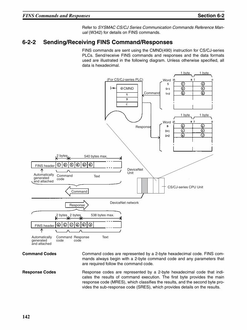
FINS Commands and Responses Section 6-2
Refer to SYSMAC CS/CJ Series Communication Commands Reference Man-ual (W342) for details on FINS commands.
6-2-2 Sending/Receiving FINS Command/ResponsesFINS commands are sent using the CMND(490) instruction for CS/CJ-seriesPLCs. Send/receive FINS commands and responses and the data formatsused are illustrated in the following diagram. Unless otherwise specified, alldata is hexadecimal.
Command Codes Command codes are represented by a 2-byte hexadecimal code. FINS com-mands always begin with a 2-byte command code and any parameters thatare required follow the command code.
Response Codes Response codes are represented by a 2-byte hexadecimal code that indi-cates the results of command execution. The first byte provides the mainresponse code (MRES), which classifies the results, and the second byte pro-vides the sub-response code (SRES), which provides details on the results.
(For CS/CJ-series PLC)
Command
Response
Word
Word
1 byte 1 byte
1 byte 1 byte
FINS header
Automatically generated and attached
2 bytes 540 bytes max.
Command code
Text
DeviceNet Unit
CS/CJ-series CPU Unit
DeviceNet network
Command
FINS header
Automatically generated and attached
2 bytes 538 bytes max.
Command code
Text
2 bytes
Response code
Response
@CMND
142
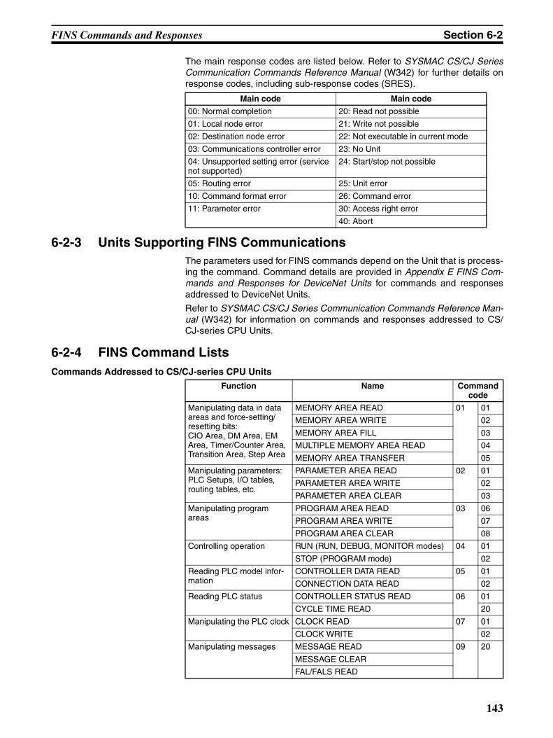
FINS Commands and Responses Section 6-2
The main response codes are listed below. Refer to SYSMAC CS/CJ SeriesCommunication Commands Reference Manual (W342) for further details onresponse codes, including sub-response codes (SRES).
6-2-3 Units Supporting FINS CommunicationsThe parameters used for FINS commands depend on the Unit that is process-ing the command. Command details are provided in Appendix E FINS Com-mands and Responses for DeviceNet Units for commands and responsesaddressed to DeviceNet Units.
Refer to SYSMAC CS/CJ Series Communication Commands Reference Man-ual (W342) for information on commands and responses addressed to CS/CJ-series CPU Units.
6-2-4 FINS Command ListsCommands Addressed to CS/CJ-series CPU Units
Main code Main code
00: Normal completion 20: Read not possible
01: Local node error 21: Write not possible
02: Destination node error 22: Not executable in current mode
03: Communications controller error 23: No Unit
04: Unsupported setting error (service not supported)
24: Start/stop not possible
05: Routing error 25: Unit error
10: Command format error 26: Command error
11: Parameter error 30: Access right error
40: Abort
Function Name Command code
Manipulating data in data areas and force-setting/resetting bits: CIO Area, DM Area, EM Area, Timer/Counter Area, Transition Area, Step Area
MEMORY AREA READ 01 01
MEMORY AREA WRITE 02
MEMORY AREA FILL 03
MULTIPLE MEMORY AREA READ 04
MEMORY AREA TRANSFER 05
Manipulating parameters: PLC Setups, I/O tables, routing tables, etc.
PARAMETER AREA READ 02 01
PARAMETER AREA WRITE 02
PARAMETER AREA CLEAR 03
Manipulating program areas
PROGRAM AREA READ 03 06
PROGRAM AREA WRITE 07
PROGRAM AREA CLEAR 08
Controlling operation RUN (RUN, DEBUG, MONITOR modes) 04 01
STOP (PROGRAM mode) 02
Reading PLC model infor-mation
CONTROLLER DATA READ 05 01
CONNECTION DATA READ 02
Reading PLC status CONTROLLER STATUS READ 06 01
CYCLE TIME READ 20
Manipulating the PLC clock CLOCK READ 07 01
CLOCK WRITE 02
Manipulating messages MESSAGE READ 09 20
MESSAGE CLEAR
FAL/FALS READ
143
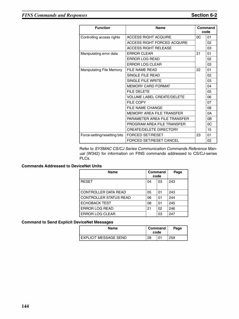
FINS Commands and Responses Section 6-2
Refer to SYSMAC CS/CJ Series Communication Commands Reference Man-ual (W342) for information on FINS commands addressed to CS/CJ-seriesPLCs.
Commands Addressed to DeviceNet Units
Command to Send Explicit DeviceNet Messages
Controlling access rights ACCESS RIGHT ACQUIRE 0C 01
ACCESS RIGHT FORCED ACQUIRE 02
ACCESS RIGHT RELEASE 03
Manipulating error data ERROR CLEAR 21 01
ERROR LOG READ 02
ERROR LOG CLEAR 03
Manipulating File Memory FILE NAME READ 22 01
SINGLE FILE READ 02
SINGLE FILE WRITE 03
MEMORY CARD FORMAT 04
FILE DELETE 05
VOLUME LABEL CREATE/DELETE 06
FILE COPY 07
FILE NAME CHANGE 08
MEMORY AREA FILE TRANSFER 0A
PARAMETER AREA FILE TRANSFER 0B
PROGRAM AREA FILE TRANSFER 0C
CREATE/DELETE DIRECTORY 15
Force-setting/resetting bits FORCED SET/RESET 23 01
FORCED SET/RESET CANCEL 02
Function Name Command code
Name Command code
Page
RESET 04 03 243
CONTROLLER DATA READ 05 01 243
CONTROLLER STATUS READ 06 01 244
ECHOBACK TEST 08 01 245
ERROR LOG READ 21 02 246
ERROR LOG CLEAR 03 247
Name Command code
Page
EXPLICIT MESSAGE SEND 28 01 259
144
Using FINS Message Communications Section 6-3
6-3 Using FINS Message CommunicationsThere are two instructions that can be executed to send and receive data fromCS/CJ-series CPU Units: SEND(090) and RECV(098). There is anotherinstruction that can be executed to send any FINS command: CMND(490).
6-3-1 Setting Node AddressesSet the nodes for FINS message communications to node addresses otherthan 0. Node address 0 has a special meaning (local node) in message com-munications. If 0 is set as a node address for the Unit, message communica-tions will not be possible.
6-3-2 Creating Routing TablesThe DeviceNet Unit functions as a Communications Unit in the same way as theSYSMAC LINK Unit, Controller Link Unit, and Ethernet Unit.
It is therefore necessary to create routing tables for the communications func-tions to be used, as shown in the table below.
Note 1. If a local network table already exists in the CPU unit being used, the De-viceNet Unit must be registered in that table.
2. The DeviceNet Unit must be registered in the local network table.
3. In all cases other than the following two exceptions, a local network tablemust be made, and the DeviceNet Unit must be registered in it.
a) When there is only one DeviceNet Unit.
b) When only multiple DeviceNet Units are mounted, with no remote I/Ocommunications.
4. A local network table is sometimes necessary even when the DeviceNetUnit is not operating across networks.
5. If you prepare a local network table inside the CPU Unit, be sure to registerthe DeviceNet Unit.
6. Even if a local network table exists inside the CPU Unit, the 7-segment dis-play of the DeviceNet Unit may indicate “HC” and FINS message/explicitmessage communications may not be possible unless the DeviceNet Unitis registered in the local network table.
Mounted Units Using master or slave functions only
Using explicit message
communications (not supported across
networks)
Using FINS message communications not
across networks
Using FINS message communications across networks
DeviceNet is the only Communications Unit mounted
Not necessary (See note 1.) Local network table (See note 2.) and relay network table are nec-essary.Multiple DeviceNet
Units mounted as Communications Units
Not necessary (See note 1.)
Local network table necessary (See note 2.)
DeviceNet Unit and other Communica-tions Unit mounted simultaneously
Local network table necessary (See note 2.)
145

Using FINS Message Communications Section 6-3
Routing TablesThe routing tables register the communications path from a CommunicationsUnit on the local PLC, such as a DeviceNet Unit, Controller Link Unit, SYS-MAC LINK Unit, or Ethernet Unit, to the network to which the remote PLC isconnected. The routing tables are made up of two tables, the local networktable and the relay network table, as described below.
Local Network Tables The local network table lists the unit numbers of the Communications Unitsmounted to the PLC and the addresses of the Networks to which each Unitbelongs. If multiple Communications Units are mounted to one PLC CPU Unit,the local network table is used to distinguish between network addresses.
The following type of table is used to show which Communications Unit datamust be sent through to reach a destination network address, when sendingdata to a network address from one PLC’s CPU Unit.
Local network: The address (1 to 127) of the network to which the Communi-cations Unit belongs.
CPU Bus Unit’s unit number: The unit number of the CPU Bus Unit.
Example
Local Network Table
The unit number of the DeviceNet Unit as a CPU Bus Unit is the number seton the rotary switches on the front panel (0 to 15). The network address is theaddress of the Network to which the CPU Bus Unit is connected (1 to 127).The network address is specified when this local network table for the routingtable is created.
Local Network Address CPU Bus Unit’s unit number
Address of local network
CPU Bus Unit’s unit number
1 00
2 01
3 02
Unit #00
Unit #01
Unit #02
Network address 1Network address 2Network address 3
146
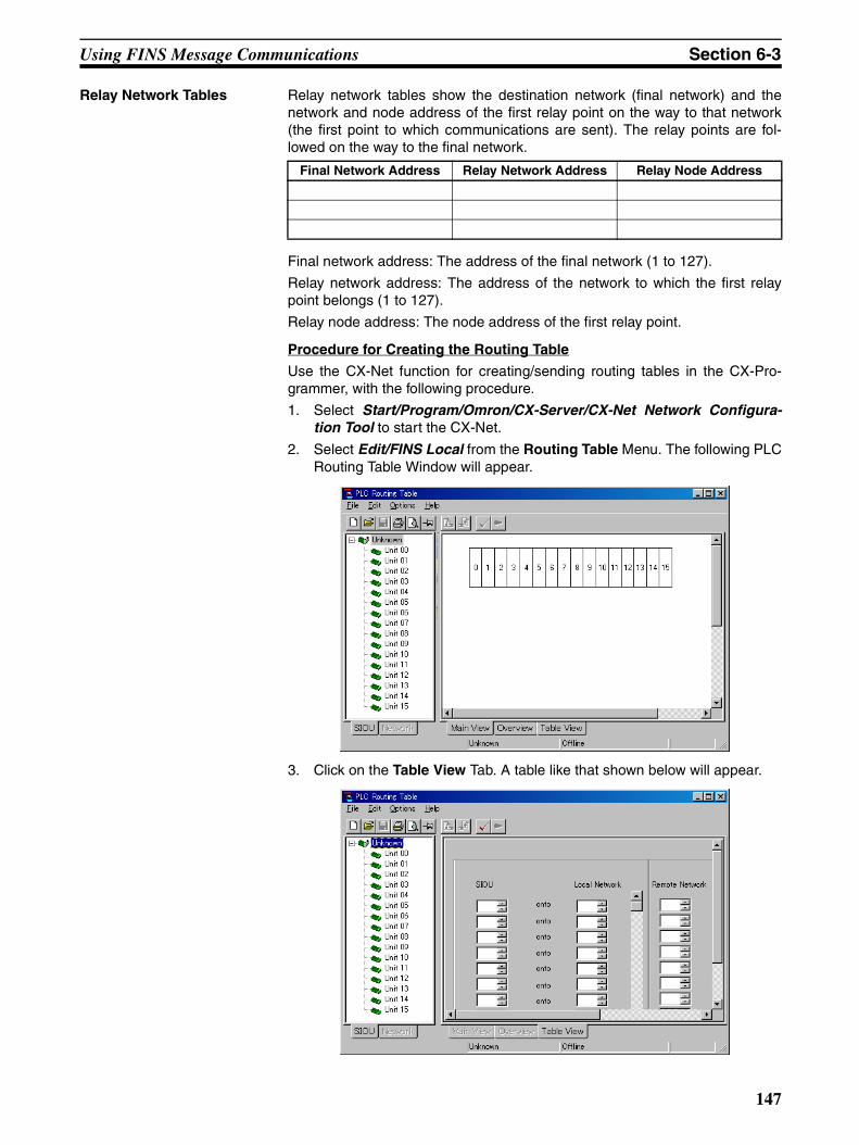
Using FINS Message Communications Section 6-3
Relay Network Tables Relay network tables show the destination network (final network) and thenetwork and node address of the first relay point on the way to that network(the first point to which communications are sent). The relay points are fol-lowed on the way to the final network.
Final network address: The address of the final network (1 to 127).
Relay network address: The address of the network to which the first relaypoint belongs (1 to 127).
Relay node address: The node address of the first relay point.
Procedure for Creating the Routing Table
Use the CX-Net function for creating/sending routing tables in the CX-Pro-grammer, with the following procedure.
1. Select Start/Program/Omron/CX-Server/CX-Net Network Configura-tion Tool to start the CX-Net.
2. Select Edit/FINS Local from the Routing Table Menu. The following PLCRouting Table Window will appear.
3. Click on the Table View Tab. A table like that shown below will appear.
Final Network Address Relay Network Address Relay Node Address
147
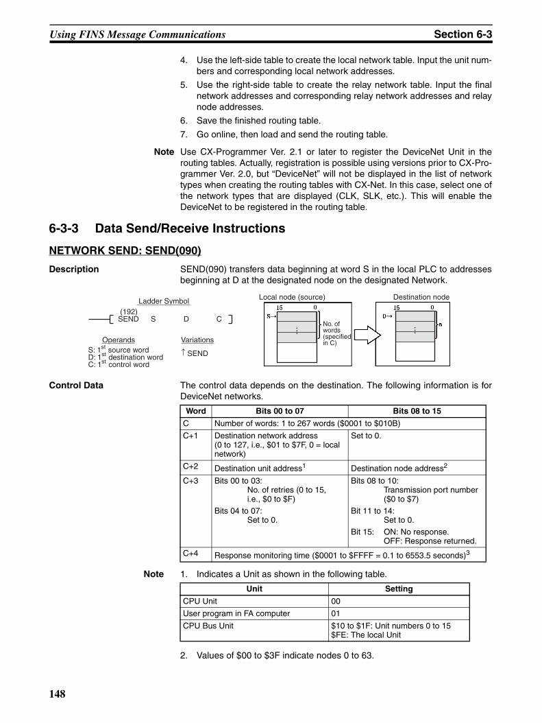
Using FINS Message Communications Section 6-3
4. Use the left-side table to create the local network table. Input the unit num-bers and corresponding local network addresses.
5. Use the right-side table to create the relay network table. Input the finalnetwork addresses and corresponding relay network addresses and relaynode addresses.
6. Save the finished routing table.
7. Go online, then load and send the routing table.
Note Use CX-Programmer Ver. 2.1 or later to register the DeviceNet Unit in therouting tables. Actually, registration is possible using versions prior to CX-Pro-grammer Ver. 2.0, but “DeviceNet” will not be displayed in the list of networktypes when creating the routing tables with CX-Net. In this case, select one ofthe network types that are displayed (CLK, SLK, etc.). This will enable theDeviceNet to be registered in the routing table.
6-3-3 Data Send/Receive Instructions
NETWORK SEND: SEND(090)
Description SEND(090) transfers data beginning at word S in the local PLC to addressesbeginning at D at the designated node on the designated Network.
Control Data The control data depends on the destination. The following information is forDeviceNet networks.
Note 1. Indicates a Unit as shown in the following table.
2. Values of $00 to $3F indicate nodes 0 to 63.
Variations
↑ SEND
(192)SEND S D C
Ladder Symbol
S: 1st source wordD: 1st destination wordC: 1st control word
Local node (source)
No. of words (specified in C)
Destination node
Operands
......
Word Bits 00 to 07 Bits 08 to 15
C Number of words: 1 to 267 words ($0001 to $010B)
C+1 Destination network address(0 to 127, i.e., $01 to $7F, 0 = local network)
Set to 0.
C+2 Destination unit address1 Destination node address2
C+3 Bits 00 to 03:No. of retries (0 to 15, i.e., $0 to $F)
Bits 04 to 07:Set to 0.
Bits 08 to 10:Transmission port number($0 to $7)
Bit 11 to 14:Set to 0.
Bit 15: ON: No response.OFF: Response returned.
C+4 Response monitoring time ($0001 to $FFFF = 0.1 to 6553.5 seconds)3
Unit Setting
CPU Unit 00
User program in FA computer 01
CPU Bus Unit $10 to $1F: Unit numbers 0 to 15$FE: The local Unit
148
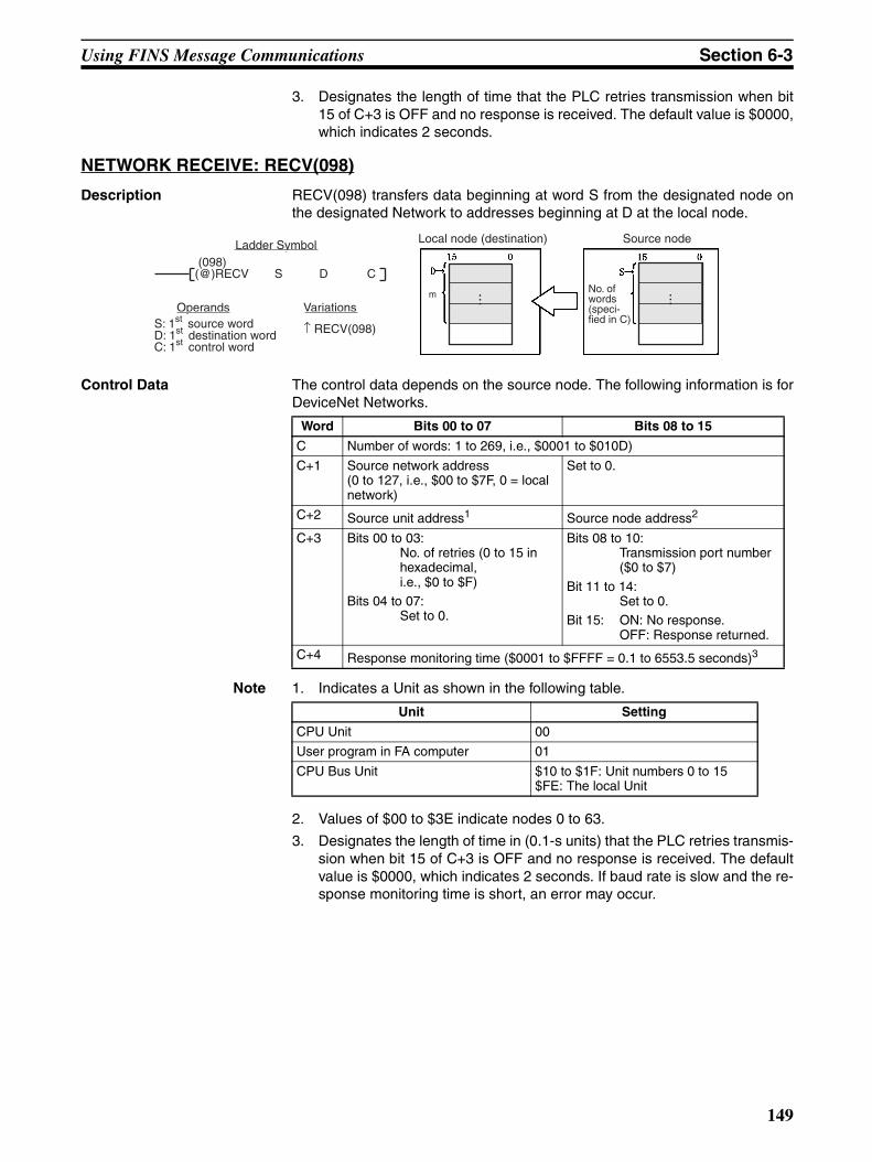
Using FINS Message Communications Section 6-3
3. Designates the length of time that the PLC retries transmission when bit15 of C+3 is OFF and no response is received. The default value is $0000,which indicates 2 seconds.
NETWORK RECEIVE: RECV(098)
Description RECV(098) transfers data beginning at word S from the designated node onthe designated Network to addresses beginning at D at the local node.
Control Data The control data depends on the source node. The following information is forDeviceNet Networks.
Note 1. Indicates a Unit as shown in the following table.
2. Values of $00 to $3E indicate nodes 0 to 63.
3. Designates the length of time in (0.1-s units) that the PLC retries transmis-sion when bit 15 of C+3 is OFF and no response is received. The defaultvalue is $0000, which indicates 2 seconds. If baud rate is slow and the re-sponse monitoring time is short, an error may occur.
Variations
↑ RECV(098)
(098)(@)RECV S D C
Ladder Symbol
S: 1st source wordD: 1st destination wordC: 1st control word
Local node (destination)
No. of words (speci-fied in C)
Source node
Operands
... ...m
Word Bits 00 to 07 Bits 08 to 15
C Number of words: 1 to 269, i.e., $0001 to $010D)
C+1 Source network address(0 to 127, i.e., $00 to $7F, 0 = local network)
Set to 0.
C+2 Source unit address1 Source node address2
C+3 Bits 00 to 03:No. of retries (0 to 15 in hexadecimal, i.e., $0 to $F)
Bits 04 to 07:Set to 0.
Bits 08 to 10:Transmission port number($0 to $7)
Bit 11 to 14:Set to 0.
Bit 15: ON: No response.OFF: Response returned.
C+4 Response monitoring time ($0001 to $FFFF = 0.1 to 6553.5 seconds)3
Unit Setting
CPU Unit 00
User program in FA computer 01
CPU Bus Unit $10 to $1F: Unit numbers 0 to 15$FE: The local Unit
149
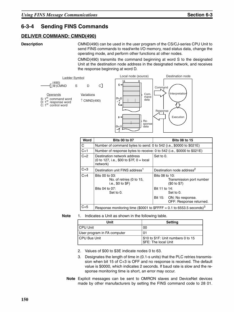
Using FINS Message Communications Section 6-3
6-3-4 Sending FINS Commands
DELIVER COMMAND: CMND(490)
Description CMND(490) can be used in the user program of the CS/CJ-series CPU Unit tosend FINS commands to read/write I/O memory, read status data, change theoperating mode, and perform other functions at other nodes.
CMND(490) transmits the command beginning at word S to the designatedUnit at the destination node address in the designated network, and receivesthe response beginning at word D.
Note 1. Indicates a Unit as shown in the following table.
2. Values of $00 to $3E indicate nodes 0 to 63.
3. Designates the length of time in (0.1-s units) that the PLC retries transmis-sion when bit 15 of C+3 is OFF and no response is received. The defaultvalue is $0000, which indicates 2 seconds. If baud rate is slow and the re-sponse monitoring time is short, an error may occur.
Note Explicit messages can be sent to OMRON slaves and DeviceNet devicesmade by other manufacturers by setting the FINS command code to 28 01.
Word Bits 00 to 07 Bits 08 to 15
C Number of command bytes to send: 0 to 542 (i.e., $0000 to $021E)
C+1 Number of response bytes to receive: 0 to 542 (i.e., $0000 to $021E)
C+2 Destination network address(0 to 127, i.e., $00 to $7F, 0 = local network)
Set to 0.
C+3 Destination unit FINS address1 Destination node address2
C+4 Bits 00 to 03:No. of retries (0 to 15, i.e., $0 to $F)
Bits 04 to 07:Set to 0.
Bits 08 to 10:Transmission port number($0 to $7)
Bit 11 to 14:Set to 0.
Bit 15: ON: No response.OFF: Response returned.
C+5 Response monitoring time ($0001 to $FFFF = 0.1 to 6553.5 seconds)3
Variations
↑ CMND(490)
(490)(@)CMND S D C
Ladder Symbol
S: 1st command wordD: 1st response wordC: 1st control word
Local node (source)
Com-mand data
Destination node
Operands
Re-sponse data
Interpretation
Execution
Command
Response
...... ...
Unit Setting
CPU Unit 00
User program in FA computer 01
CPU Bus Unit $10 to $1F: Unit numbers 0 to 15$FE: The local Unit
150
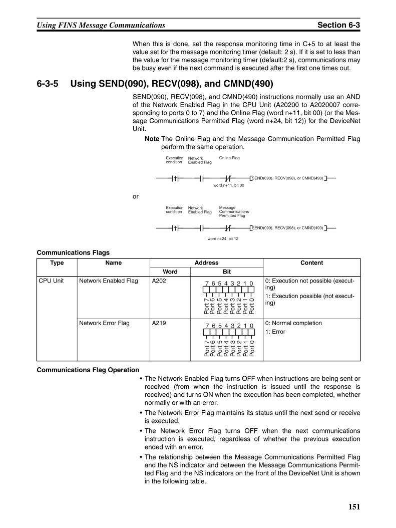
Using FINS Message Communications Section 6-3
When this is done, set the response monitoring time in C+5 to at least thevalue set for the message monitoring timer (default: 2 s). If it is set to less thanthe value for the message monitoring timer (default:2 s), communications maybe busy even if the next command is executed after the first one times out.
6-3-5 Using SEND(090), RECV(098), and CMND(490)SEND(090), RECV(098), and CMND(490) instructions normally use an ANDof the Network Enabled Flag in the CPU Unit (A20200 to A2020007 corre-sponding to ports 0 to 7) and the Online Flag (word n+11, bit 00) (or the Mes-sage Communications Permitted Flag (word n+24, bit 12)) for the DeviceNetUnit.
Note The Online Flag and the Message Communication Permitted Flagperform the same operation.
or
Communications Flags
Communications Flag Operation• The Network Enabled Flag turns OFF when instructions are being sent or
received (from when the instruction is issued until the response isreceived) and turns ON when the execution has been completed, whethernormally or with an error.
• The Network Error Flag maintains its status until the next send or receiveis executed.
• The Network Error Flag turns OFF when the next communicationsinstruction is executed, regardless of whether the previous executionended with an error.
• The relationship between the Message Communications Permitted Flagand the NS indicator and between the Message Communications Permit-ted Flag and the NS indicators on the front of the DeviceNet Unit is shownin the following table.
SEND(090), RECV(098), or CMND(490)
Execution condition
Network Enabled Flag
Online Flag
word n+11, bit 00
SEND(090), RECV(098), or CMND(490)
Execution condition
Network Enabled Flag
Message Communications Permitted Flag
word n+24, bit 12
Type Name Address Content
Word Bit
CPU Unit Network Enabled Flag A202 0: Execution not possible (execut-ing)1: Execution possible (not execut-ing)
Network Error Flag A219 0: Normal completion1: Error
7 6 5 4 3 2 1 0
Por
t 0P
ort 1
Por
t 2P
ort 3
Por
t 4P
ort 5
Por
t 6P
ort 7
7 6 5 4 3 2 1 0
Por
t 0P
ort 1
Por
t 2P
ort 3
Por
t 4P
ort 5
Por
t 6P
ort 7
151

Using FINS Message Communications Section 6-3
Communications Instructions Completion Codes
The status at the completion of the execution of network communicationsinstructions is shown at the words indicated in the following table, as FINScompletion codes. During execution of the instructions the status will be 00 or$0000 and this will be reflected at the end of the execution of the networkcommunications instruction.
Note For the CS/CJ-series, the completion codes are stored as 2 bytes ofdata (1 word) upon completion of the execution of SEND(090),RECV(098), and CMND(490). These codes are the same as the re-sponse codes for FINS commands. The first byte of the completioncode is placed in bits 08 to 15 and the second byte is placed in bits00 to 07.
Timing of Reading Responses
Responses should be read on the rising edge (upward differentiation) of theNetwork Enabled Flag, as shown in the following diagram.
Send/Receive Data Areas
The size of the data areas that can be used with SEND and RECV dependson the PLC that is being used. The following table shows the areas that canbe used for CS/CJ-series PLCs.
Message Communications
Permitted Flag
Network status NS indicator
ON Communications connection made (network nor-mal)
Lit green
Communications connection not made (network normal, but communications not established)
Flashing green
Non-fatal communications error (error in one or more Slaves)
Flashing red
OFF Offline or power supply is OFF (no power supply, resetting, minor failure, or send error)
Not lit
Fatal communications error Lit red
Words Functions
Port #0 to #7Completion Codes (A203 to A210)
A203 to A210 contain the completion codes for the results of communications instruction execution for ports #0 to #7, respectively.
Data Area Range
CIO Area CIO 0000 to CIO 6143
Work Area WR W000 to W511
Holding Area H000 to H511
Network En-abled Flag
ExecutionError Flag
Completion code
Communications instruction
Previous code
Instruction 1 executed
Instruction 2 executed
Instruction 3 executed
00 Normal end
00
04 Busy
00
00 Normal end
00
1
0
1
0
Network Enabled Flag
Processing to read response
152
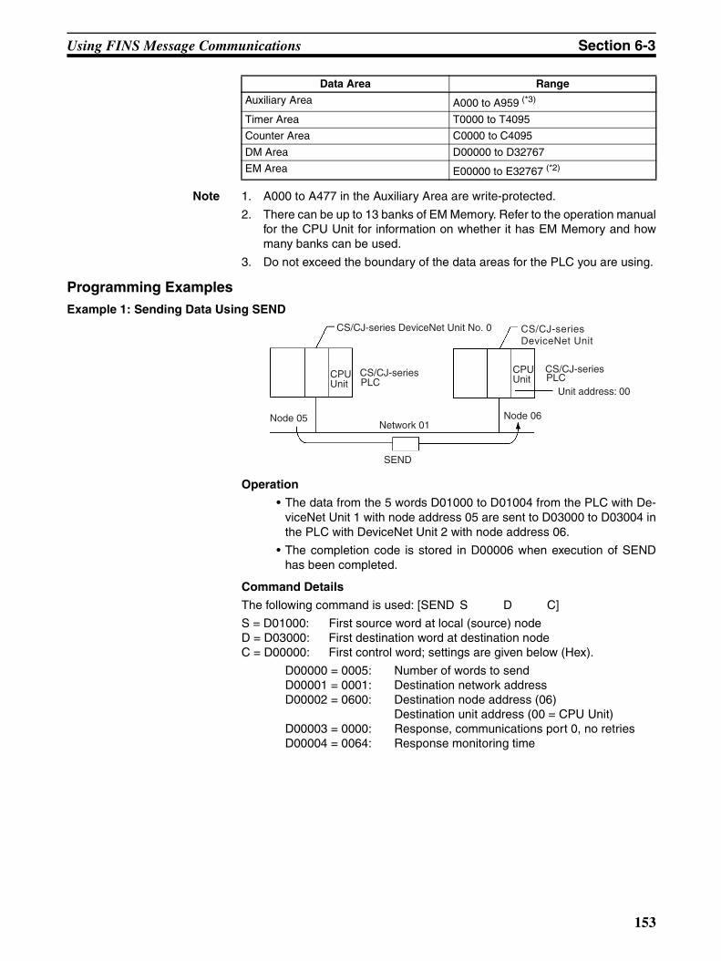
Using FINS Message Communications Section 6-3
Note 1. A000 to A477 in the Auxiliary Area are write-protected.
2. There can be up to 13 banks of EM Memory. Refer to the operation manualfor the CPU Unit for information on whether it has EM Memory and howmany banks can be used.
3. Do not exceed the boundary of the data areas for the PLC you are using.
Programming ExamplesExample 1: Sending Data Using SEND
Operation
• The data from the 5 words D01000 to D01004 from the PLC with De-viceNet Unit 1 with node address 05 are sent to D03000 to D03004 inthe PLC with DeviceNet Unit 2 with node address 06.
• The completion code is stored in D00006 when execution of SENDhas been completed.
Command Details
The following command is used: [SEND S D C]
S = D01000: First source word at local (source) nodeD = D03000: First destination word at destination nodeC = D00000: First control word; settings are given below (Hex).
D00000 = 0005: Number of words to sendD00001 = 0001: Destination network addressD00002 = 0600: Destination node address (06)
Destination unit address (00 = CPU Unit)D00003 = 0000: Response, communications port 0, no retriesD00004 = 0064: Response monitoring time
Auxiliary Area A000 to A959 (*3)
Timer Area T0000 to T4095
Counter Area C0000 to C4095
DM Area D00000 to D32767
EM Area E00000 to E32767 (*2)
Data Area Range
CS/CJ-series DeviceNet Unit No. 0
CS/CJ-series PLC
CPU Unit
Node 05Network 01
SEND
Node 06
Unit address: 00
CPU Unit PLC
CS/CJ-series
CS/CJ-series DeviceNet Unit
153
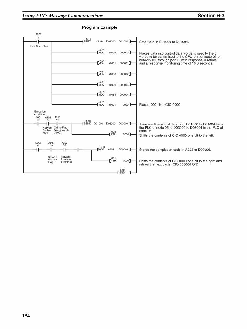
Using FINS Message Communications Section 6-3
Program Example
(021)MOV A503 D00006
11A202
(021)MOV #0005 D00000
(021)MOV #0001 D00001
(021)MOV #0600 D00002
(021)MOV #0000 D00003
(025)ASL 0000
00000
A20200
000001
(071)BSET #1234 D01000 D01004 Sets 1234 in D01000 to D01004.
Places data into control data words to specify the 5 words to be transmitted to the CPU Unit of node 06 of network 01, through port 0, with response, 0 retries, and a response monitoring time of 10.0 seconds.
Shifts the contents of CIO 0000 one bit to the right and retries the next cycle (CIO 000000 ON).
Transfers 5 words of data from D01000 to D01004 from the PLC of node 05 to D03000 to D03004 in the PLC of node 06.Shifts the contents of CIO 0000 one bit to the left.
Stores the completion code in A203 to D00006.
NetworkEnabled Flag
(021)MOV #0064 D00004
(021)MOV #0001 0000
First Scan Flag
151100
(061)ASR 0000
Execution condition
Online Flag(Word n+11, bit 00)
00 08
NetworkEnabled Flag
NetworkExecution Error Flag
Places 0001 into CIO 0000
(001)END
(090)SEND D01000 D03000 D00000
A202 A202
154
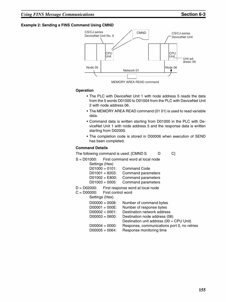
Using FINS Message Communications Section 6-3
Example 2: Sending a FINS Command Using CMND
Operation
• The PLC with DeviceNet Unit 1 with node address 5 reads the datafrom the 5 words D01000 to D01004 from the PLC with DeviceNet Unit2 with node address 06.
• The MEMORY AREA READ command (01 01) is used to read variabledata.
• Command data is written starting from D01000 in the PLC with De-viceNet Unit 1 with node address 5 and the response data is writtenstarting from D02000.
• The completion code is stored in D00006 when execution of SENDhas been completed.
Command Details
The following command is used: [CMND S D C]
S = D01000: First command word at local nodeSettings (Hex)D01000 = 0101: Command CodeD01001 = 8203: Command parametersD01002 = E800: Command parametersD01003 = 0005: Command parameters
D = D02000: First response word at local node C = D00000: First control word
Settings (Hex).
D00000 = 0008: Number of command bytesD00001 = 000E: Number of response bytesD00002 = 0001: Destination network addressD00003 = 0600: Destination node address (06)
Destination unit address (00 = CPU Unit)D00004 = 0000: Response, communications port 0, no retriesD00005 = 0064: Response monitoring time
CS/CJ-series DeviceNet Unit No. 0
CPU Unit
Node 05Network 01
CMND
Node 06
Unit ad-dress: 00
CPU Unit
CS/CJ-seriesDeviceNet Unit
MEMORY AREA READ command
155
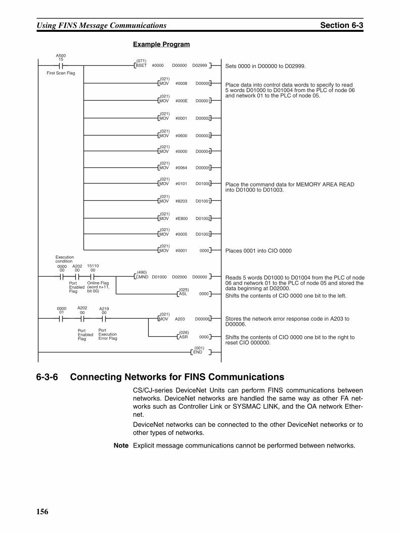
Using FINS Message Communications Section 6-3
Example Program
6-3-6 Connecting Networks for FINS CommunicationsCS/CJ-series DeviceNet Units can perform FINS communications betweennetworks. DeviceNet networks are handled the same way as other FA net-works such as Controller Link or SYSMAC LINK, and the OA network Ether-net.
DeviceNet networks can be connected to the other DeviceNet networks or toother types of networks.
Note Explicit message communications cannot be performed between networks.
(021)MOV A203 D00006
A50015
(021)MOV #0008 D00000
(021)MOV #000E D00001
(021)MOV #0001 D00002
(021)MOV #0600 D00003
(490)CMND D01000 D02000 D00000
(025)ASL 0000
000000
A202
000001
(071)BSET #0000 D00000 D02999 Sets 0000 in D00000 to D02999.
Place data into control data words to specify to read 5 words D01000 to D01004 from the PLC of node 06 and network 01 to the PLC of node 05.
Shifts the contents of CIO 0000 one bit to the right to reset CIO 000000.
Reads 5 words D01000 to D01004 from the PLC of node 06 and network 01 to the PLC of node 05 and stored the data beginning at D02000.Shifts the contents of CIO 0000 one bit to the left.
Stores the network error response code in A203 to D00006.
Port Enabled Flag
(021)MOV #0000 D00004
(021)MOV #0064 D00005
First Scan Flag
1511000
(026)ASR 0000
Execution condition
Online Flag(word n+11, bit 00)
Port Enabled Flag
Port Execution Error Flag
Places 0001 into CIO 0000
(021)MOV #0101 D01000
(021)MOV #8203 D01001
(021)MOV #E800 D01002
(021)MOV #0005 D01003
(021)MOV #0001 0000
Place the command data for MEMORY AREA READ into D01000 to D01003.
00
00 00A202 A219
(001)END
156
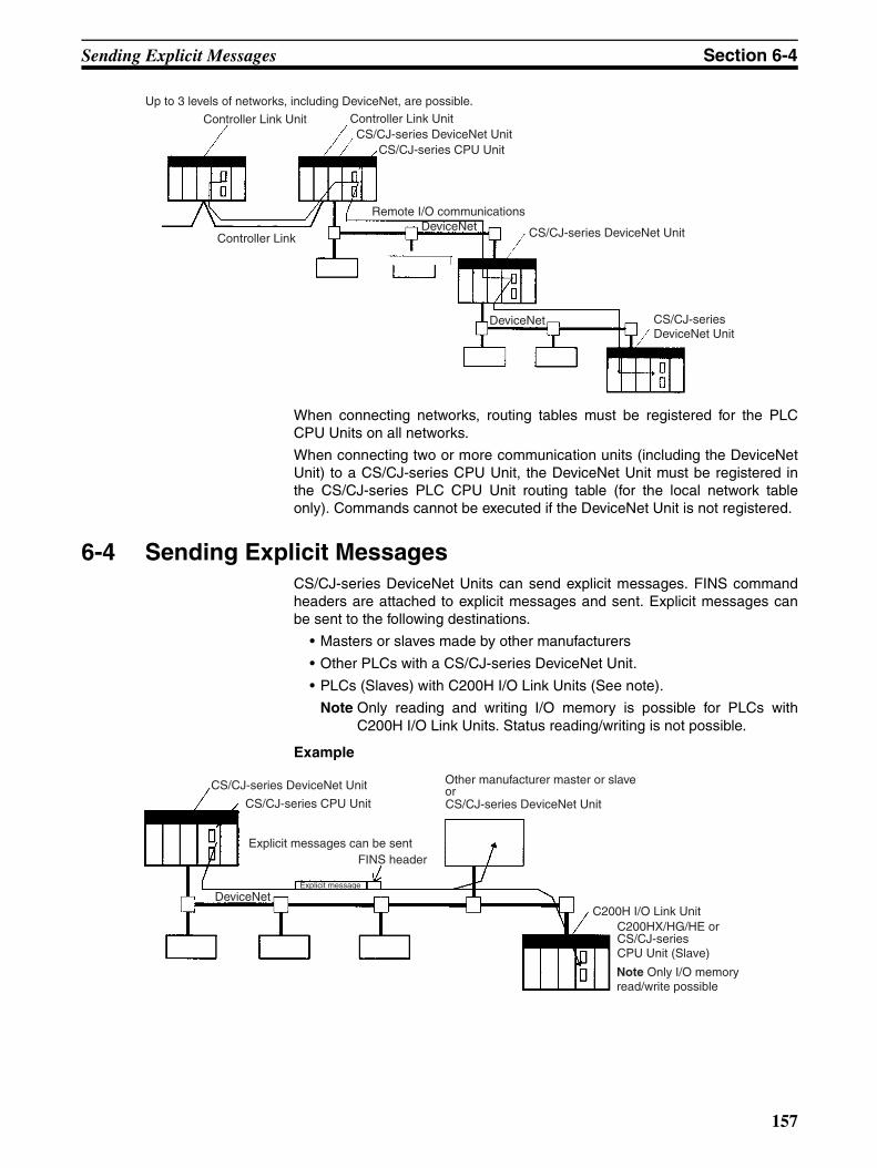
Sending Explicit Messages Section 6-4
When connecting networks, routing tables must be registered for the PLCCPU Units on all networks.
When connecting two or more communication units (including the DeviceNetUnit) to a CS/CJ-series CPU Unit, the DeviceNet Unit must be registered inthe CS/CJ-series PLC CPU Unit routing table (for the local network tableonly). Commands cannot be executed if the DeviceNet Unit is not registered.
6-4 Sending Explicit MessagesCS/CJ-series DeviceNet Units can send explicit messages. FINS commandheaders are attached to explicit messages and sent. Explicit messages canbe sent to the following destinations.
• Masters or slaves made by other manufacturers
• Other PLCs with a CS/CJ-series DeviceNet Unit.
• PLCs (Slaves) with C200H I/O Link Units (See note).
Note Only reading and writing I/O memory is possible for PLCs withC200H I/O Link Units. Status reading/writing is not possible.
Example
Up to 3 levels of networks, including DeviceNet, are possible.
Controller Link Unit Controller Link UnitCS/CJ-series DeviceNet Unit
CS/CJ-series CPU Unit
Remote I/O communications
Controller Link DeviceNet CS/CJ-series DeviceNet Unit
DeviceNet CS/CJ-seriesDeviceNet Unit
CS/CJ-series DeviceNet Unit
CS/CJ-series CPU Unit
Explicit messages can be sent
Explicit message
FINS header
DeviceNet
Other manufacturer master or slave or
C200H I/O Link UnitC200HX/HG/HE or CS/CJ-series CPU Unit (Slave)
Note Only I/O memory read/write possible
CS/CJ-series DeviceNet Unit
157
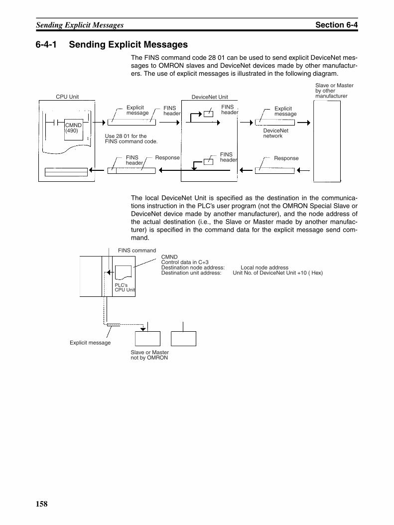
Sending Explicit Messages Section 6-4
6-4-1 Sending Explicit MessagesThe FINS command code 28 01 can be used to send explicit DeviceNet mes-sages to OMRON slaves and DeviceNet devices made by other manufactur-ers. The use of explicit messages is illustrated in the following diagram.
The local DeviceNet Unit is specified as the destination in the communica-tions instruction in the PLC’s user program (not the OMRON Special Slave orDeviceNet device made by another manufacturer), and the node address ofthe actual destination (i.e., the Slave or Master made by another manufac-turer) is specified in the command data for the explicit message send com-mand.
CPU Unit
CMND(490)
Explicit message
FINS header
Use 28 01 for the FINS command code.
FINS header
Response
DeviceNet Unit
FINS header
FINS header
Explicit message
Response
DeviceNet network
Slave or Master by other manufacturer
FINS command
PLC's CPU Unit
Explicit message
Slave or Master not by OMRON
CMNDControl data in C+3Destination node address: Local node addressDestination unit address: Unit No. of DeviceNet Unit +10 ( Hex)
158
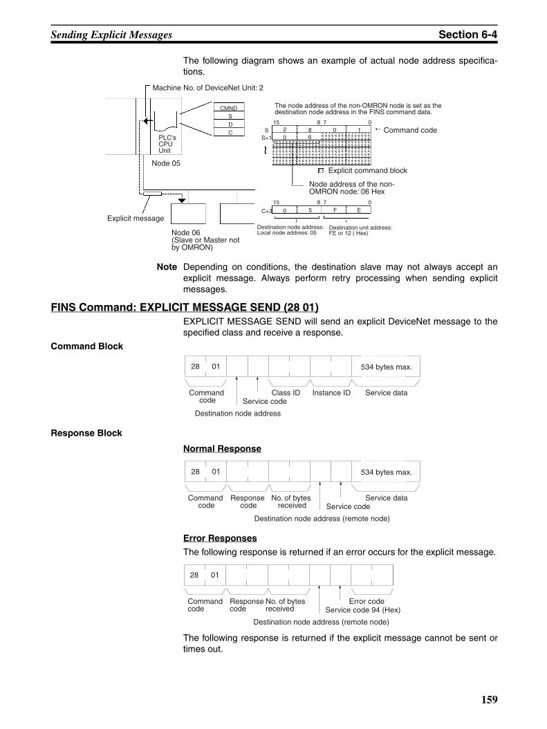
Sending Explicit Messages Section 6-4
The following diagram shows an example of actual node address specifica-tions.
Note Depending on conditions, the destination slave may not always accept anexplicit message. Always perform retry processing when sending explicitmessages.
FINS Command: EXPLICIT MESSAGE SEND (28 01)EXPLICIT MESSAGE SEND will send an explicit DeviceNet message to thespecified class and receive a response.
Command Block
Response Block
Normal Response
Error Responses
The following response is returned if an error occurs for the explicit message.
The following response is returned if the explicit message cannot be sent ortimes out.
PLC's CPU Unit
Explicit message
Node 06(Slave or Master not by OMRON)
Destination node address:Local node address: 05
Node 05
Destination unit address:FE or 12 ( Hex)
The node address of the non-OMRON node is set as the destination node address in the FINS command data.
Command code
Node address of the non-OMRON node: 06 Hex
Explicit command block
Machine No. of DeviceNet Unit: 2
CMNDSDC S
S+1
2 8 0 115 8 7 0
15 8 7 0
0 6
0C+3 5 F E
0128
Destination node address
Instance ID Service dataClass IDCommand code
534 bytes max.
Service code
0128
Destination node address (remote node)
No. of bytes received
Service dataResponse code
Command code
534 bytes max.
Service code
0128
Destination node address (remote node)
Service code 94 (Hex)No. of bytes received
Response code
Command code
Error code
159

Sending Explicit Messages Section 6-4
Parameters Destination node address (command): The node address of the destinationof the explicit message. (The node address of the local DeviceNet Unit isspecified in the control data for the CMND(490) or IOWR instruction, but thenode address of the actual destination is specified here in the FINS com-mand.)
Service code (command, response): A service code defined for DeviceNet.In a normal response, bit 15 of the service code specified in the command willbe turned ON and returned. In an error response, 94 Hex will always bereturned.
Class ID (command): The class ID of the destination of the explicit message.
Instance ID (command): The instance ID of the destination of the explicitmessage.
Service data (command, response): The data defined for the servicescodes.
No. of bytes received (response): The number of bytes received from thedestination node address (remote node).
Destination node address (remote node): The node address of theOMRON Special I/O Slave Unit or Slave manufactured by another companyto which the explicit message was sent is returned.
Error code (response): An error code defined by DeviceNet.
Note 1. This command sends a DeviceNet-defined explicit message to an OM-RON Special I/O Slave Unit or a Slave manufactured by another companyand receives a response.
2. Unlike other FINS commands, this command is addressed to the local De-viceNet Unit. The actual destination of the explicit message is given in thecommand data, as described above.
3. If the DeviceNet Unit receives an explicit message, it will automatically re-turn a response.
4. Refer to the DeviceNet Specification for details on parameters for explicitmessages.
5. Contact the Open DeviceNet Vendor Association, Inc. (ODVA) at 8222Wiles Road, Suite 287, Coral Springs, FL 33067 USA (phone: 954-340-5412, fax: 954-340-5413, e-mail: [email protected], Home page:http://www.odva.org/) to obtain copies of the specification.
6. For details on explicit messages to OMRON Special I/O Slaves, refer tothe DeviceNet Slaves Operation Manual (W347).
6-4-2 Sending Explicit Messages Using CMND(490)CMND(490) can be used in the CPU Unit ladder program of the CS/CJ-seriesDeviceNet Unit to send explicit messages.
FINS command headers are attached to the explicit messages and sent.
After the FINS command header and the FINS completion code are sent, theexplicit message response is received.
The following command is used: [ CMND S D C ]
S: First command word
0128
Response code
Command code
160
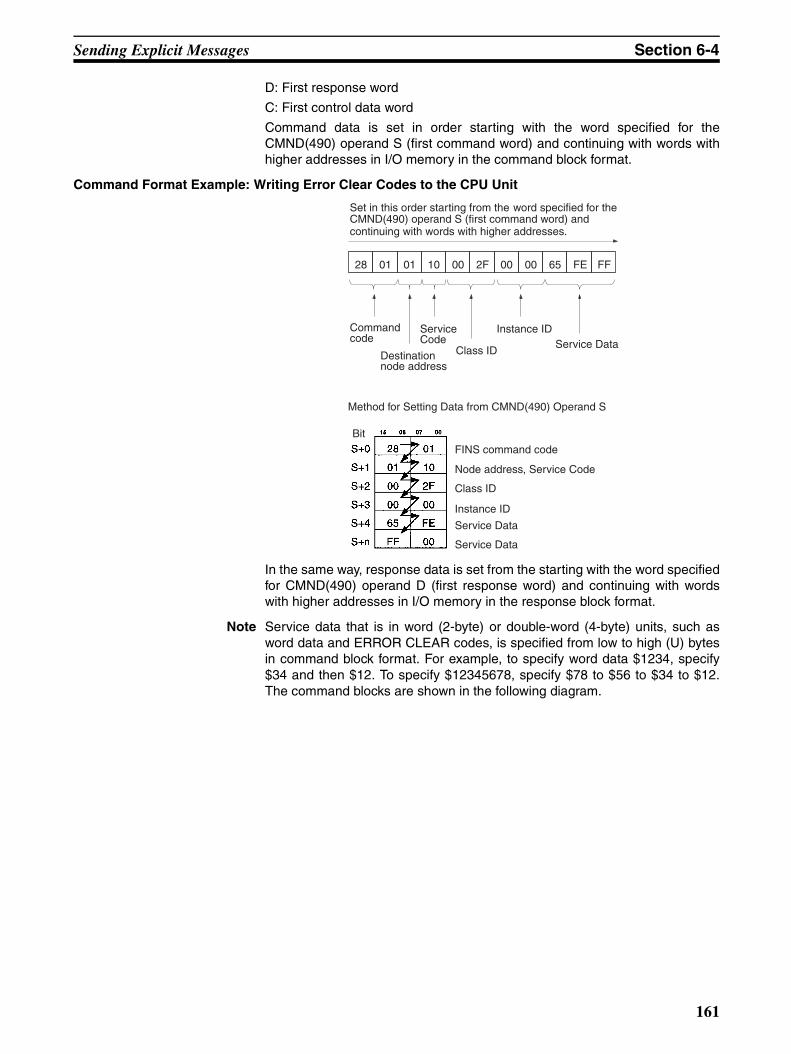
Sending Explicit Messages Section 6-4
D: First response word
C: First control data word
Command data is set in order starting with the word specified for theCMND(490) operand S (first command word) and continuing with words withhigher addresses in I/O memory in the command block format.
Command Format Example: Writing Error Clear Codes to the CPU Unit
In the same way, response data is set from the starting with the word specifiedfor CMND(490) operand D (first response word) and continuing with wordswith higher addresses in I/O memory in the response block format.
Note Service data that is in word (2-byte) or double-word (4-byte) units, such asword data and ERROR CLEAR codes, is specified from low to high (U) bytesin command block format. For example, to specify word data $1234, specify$34 and then $12. To specify $12345678, specify $78 to $56 to $34 to $12.The command blocks are shown in the following diagram.
Set in this order starting from the word specified for the CMND(490) operand S (first command word) and continuing with words with higher addresses.
Command code
Destination node address
Service Code
Class ID
Instance IDService Data
Method for Setting Data from CMND(490) Operand S
Bit
FINS command code
Node address, Service Code
Class ID
Instance ID
Service Data
Service Data
28 01 01 10 00 2F 00 00 65 FE FF
161

Sending Explicit Messages Section 6-4
The response format data in service data that is in word (2-byte) or double-word (4-byte) units, such as word data and ERROR CLEAR codes, is alsospecified from low to high bytes in response block format
Example: Sending Explicit Messages Using CMND(490)
Operation The vendor code is read from a Slave (OMRON vendor code: 002F Hex)using the EXPLICIT MESSAGE SEND command, 28 01. The command datais written starting at DM01000, and the response data is stored starting atD02000. When execution of CMND(490) has been completed, the completioncode is stored in D00006 and the instruction is executed again.
Command Details The following command is used: [ CMND S D C ]
S = D01000: First command word at local node
Settings (Hex)D01000 = 2801: Command CodeD01001 = 0B0E: Slave node address: 11
Service code: 0ED01002 = 0001: Class ID: 0001D01003 = 0001: Instance ID: 0001D01004 = 0100: Attribute ID: 01
D = D02000: First response word at local node C = D00000: First control word
Command Block
Eg. For $1234 Eg. For $15678234
Service Data Service Data
The format from CMND(490) operand S onwards will be set as follows:
Example: $1234 Example: $12345678
From higher byte From higher byteBit Bit
From lower byte
From lower byteBit
Bit
DeviceNet Unit No. 0
CMND(490) instruction
PLC's CPU Unit
Node address 05Unit address FE Hex or 10 Hex
Explicit message Slave node 11
162
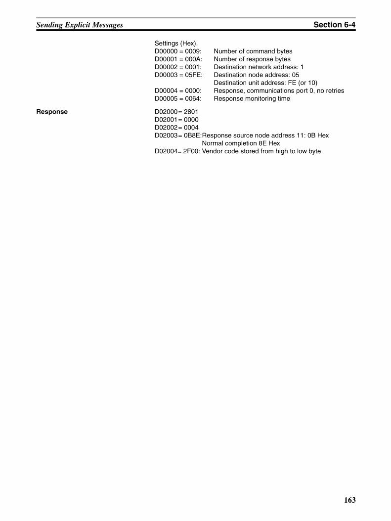
Sending Explicit Messages Section 6-4
Settings (Hex).D00000 = 0009: Number of command bytesD00001 = 000A: Number of response bytesD00002 = 0001: Destination network address: 1D00003 = 05FE: Destination node address: 05
Destination unit address: FE (or 10)D00004 = 0000: Response, communications port 0, no retriesD00005 = 0064: Response monitoring time
Response D02000= 2801D02001= 0000D02002= 0004D02003= 0B8E:Response source node address 11: 0B Hex
Normal completion 8E HexD02004= 2F00: Vendor code stored from high to low byte
163
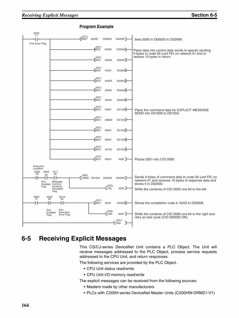
Receiving Explicit Messages Section 6-5
Program Example
6-5 Receiving Explicit MessagesThis CS/CJ-series DeviceNet Unit contains a PLC Object. The Unit willreceive messages addressed to the PLC Object, process service requestsaddressed to the CPU Unit, and return responses.
The following services are provided by the PLC Object.
• CPU Unit status read/write
• CPU Unit I/O memory read/write
The explicit messages can be received from the following sources:
• Masters made by other manufacturers
• PLCs with C200H-series DeviceNet Master Units (C200HW-DRM21-V1)
(021)MOV A203 D00006
A20011
(021)MOV #0009 D00000
(021)MOV #000A D00001
(021)MOV #0001 D00002
(021)MOV #05FE D00003
(490)CMND D01000 D02000 D00000
(025)ASL 0000
000000
A202
000001
(071)BSET #0000 D00000 D02999 Sets 0000 in D00000 to D02999.
Place data into control data words to specify sending 9 bytes to node 05 (unit FE) on network 01 and to receive 10 bytes in return.
Shifts the contents of CIO 0000 one bit to the right and retry at next cycle (CIO 000000 ON).
Sends 9 bytes of command data to node 05 (unit FE) on network 01 and receives 10 bytes of response data and stores it in D02000.
Shifts the contents of CIO 0000 one bit to the left.
Stores the completion code in A203 to D00006.
Port Enabled Flag
(021)MOV #0000 D00004
(021)MOV #0064 D00005
First Scan Flag
151100
(026)ASR 0000
Execution condition
Message Commu-nications Permitted Flag
A20200
A21900
Port Enabled Flag
Port Execution Error Flag
(021)MOV #2801 D01000
(021)MOV #0B0E D01001
(021)MOV #0001 D01002
(021)MOV #0001 D01003
(021)MOV #0100 D01004
Place the command data for EXPLICIT MESSAGE SEND into D01000 to D01004.
Places 0001 into CIO 0000 (021)MOV #0001 0000
00
(001)END
164
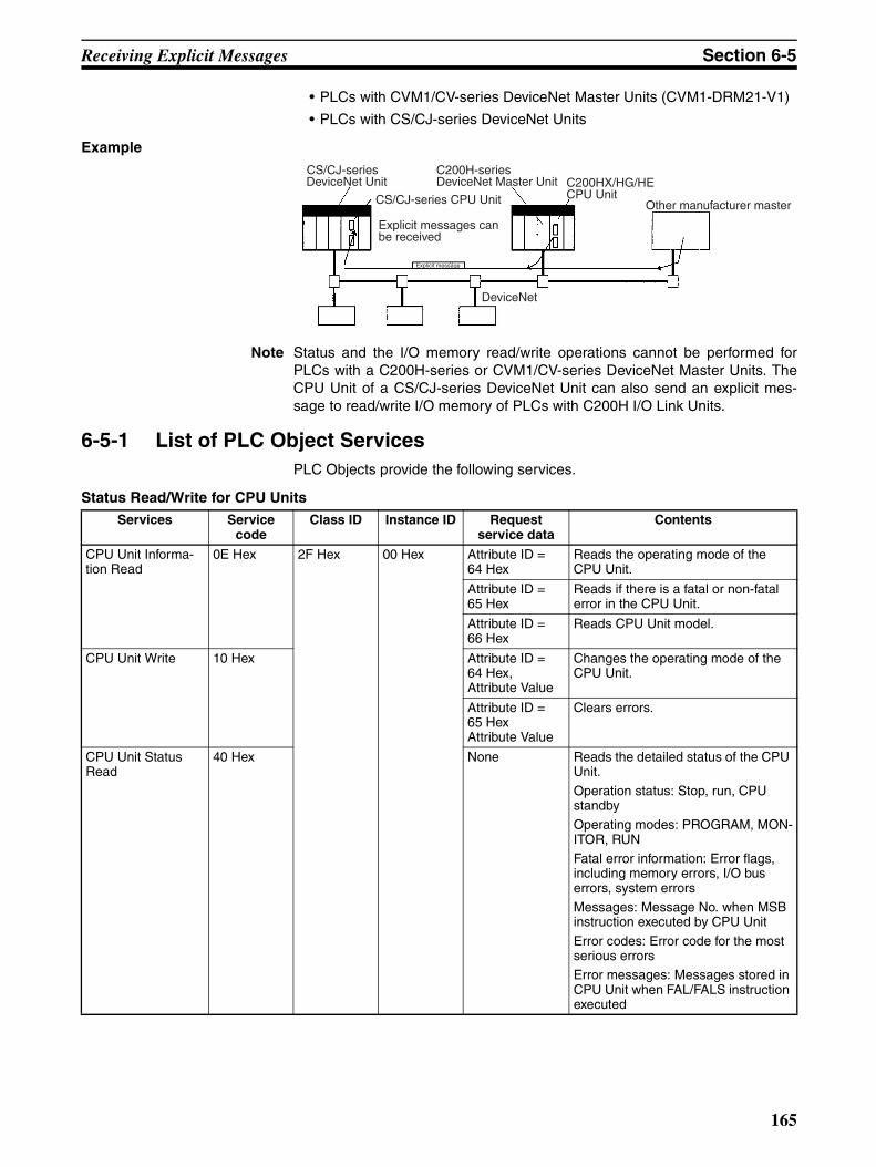
Receiving Explicit Messages Section 6-5
• PLCs with CVM1/CV-series DeviceNet Master Units (CVM1-DRM21-V1)
• PLCs with CS/CJ-series DeviceNet Units
Example
Note Status and the I/O memory read/write operations cannot be performed forPLCs with a C200H-series or CVM1/CV-series DeviceNet Master Units. TheCPU Unit of a CS/CJ-series DeviceNet Unit can also send an explicit mes-sage to read/write I/O memory of PLCs with C200H I/O Link Units.
6-5-1 List of PLC Object ServicesPLC Objects provide the following services.
Status Read/Write for CPU Units
CS/CJ-series DeviceNet Unit
CS/CJ-series CPU Unit
C200H-series DeviceNet Master Unit C200HX/HG/HE
CPU UnitOther manufacturer master
Explicit messages can be received
Explicit message
DeviceNet
Services Service code
Class ID Instance ID Request service data
Contents
CPU Unit Informa-tion Read
0E Hex 2F Hex 00 Hex Attribute ID = 64 Hex
Reads the operating mode of the CPU Unit.
Attribute ID = 65 Hex
Reads if there is a fatal or non-fatal error in the CPU Unit.
Attribute ID = 66 Hex
Reads CPU Unit model.
CPU Unit Write 10 Hex Attribute ID = 64 Hex,Attribute Value
Changes the operating mode of the CPU Unit.
Attribute ID = 65 HexAttribute Value
Clears errors.
CPU Unit Status Read
40 Hex None Reads the detailed status of the CPU Unit.
Operation status: Stop, run, CPU standbyOperating modes: PROGRAM, MON-ITOR, RUN Fatal error information: Error flags, including memory errors, I/O bus errors, system errorsMessages: Message No. when MSB instruction executed by CPU Unit
Error codes: Error code for the most serious errorsError messages: Messages stored in CPU Unit when FAL/FALS instruction executed
165
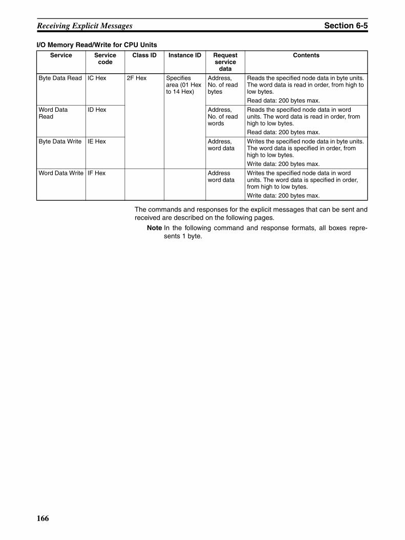
Receiving Explicit Messages Section 6-5
I/O Memory Read/Write for CPU Units
The commands and responses for the explicit messages that can be sent andreceived are described on the following pages.
Note In the following command and response formats, all boxes repre-sents 1 byte.
Service Service code
Class ID Instance ID Request service
data
Contents
Byte Data Read IC Hex 2F Hex Specifies area (01 Hex to 14 Hex)
Address, No. of read bytes
Reads the specified node data in byte units. The word data is read in order, from high to low bytes.
Read data: 200 bytes max.
Word Data Read
ID Hex Address, No. of read words
Reads the specified node data in word units. The word data is read in order, from high to low bytes.Read data: 200 bytes max.
Byte Data Write IE Hex Address, word data
Writes the specified node data in byte units. The word data is specified in order, from high to low bytes.
Write data: 200 bytes max.
Word Data Write IF Hex Address word data
Writes the specified node data in word units. The word data is specified in order, from high to low bytes.Write data: 200 bytes max.
166
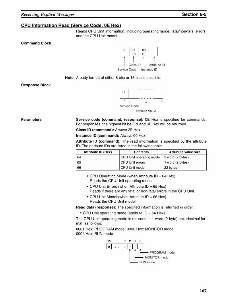
Receiving Explicit Messages Section 6-5
CPU Information Read (Service Code: 0E Hex)Reads CPU Unit information, including operating mode, fatal/non-fatal errors,and the CPU Unit model.
Command Block
Note A body format of either 8 bits or 16 bits is possible.
Response Block
Parameters Service code (command, response): 0E Hex is specified for commands.For responses, the highest bit be ON and 8E Hex will be returned.
Class ID (command): Always 2F Hex.
Instance ID (command): Always 00 Hex.
Attribute ID (command): The read information is specified by the attributeID. The attribute IDs are listed in the following table.
• CPU Operating Mode (when Attribute ID = 64 Hex)Reads the CPU Unit operating mode.
• CPU Unit Errors (when Attribute ID = 65 Hex)Reads if there are any fatal or non-fatal errors in the CPU Unit.
• CPU Unit Model (when Attribute ID = 66 Hex)Reads the CPU Unit model.
Read data (response): The specified information is returned in order.
• CPU Unit operating mode (attribute ID = 64 Hex).
The CPU Unit operating mode is returned in 1-word (2-byte) hexadecimal for-mat, as follows:
0001 Hex: PROGRAM mode; 0002 Hex: MONITOR mode; 0004 Hex: RUN mode
Class ID
Instance ID
0E 2F(*)
00 (*)
Attribute ID
Service Code
8E
Service Code
Attribute Value
Attribute ID (Hex) Contents Attribute value size
64 CPU Unit operating mode 1 word (2 bytes)
65 CPU Unit errors 1 word (2 bytes)
66 CPU Unit model 22 bytes
PROGRAM mode
MONITOR mode
RUN mode
167

Receiving Explicit Messages Section 6-5
Note The codes for the above modes are 1-word (2-byte) data and are returned inlow byte first. For example, for PROGRAM mode, the code is returned as 01Hex followed by 00 Hex.
• CPU Unit Errors (when Attribute ID = 65 Hex)
The CPU Unit fatal/non-fatal error data is returned in 1-word (2-byte) hexa-decimal format, as follows:
01 Hex: Error; 00 Hex: No error.
• CPU Unit Model (when Attribute ID = 65 Hex)
The CPU Unit model is returned in ASCII.
Size: 2 bytes (Always 1400 Hex) + Model: 20 bytes (fixed). Unused area isfilled with 20 Hex (spaces) and returned.
CPU Unit Write (Service Code: 10 Hex)This PLC Object service writes CPU Unit information, including the operatingmode and clearing errors.
Command Block
Note A body format of either 8 bits or 16 bits is possible.
Response Block
Parameters Service code (command, response): 10 Hex is specified for commands.For responses, the highest bit will turn ON and 90E Hex will be returned.
Class ID (command): Always 2F Hex.
Instance ID (command): Always 00 Hex.
Attribute ID (command): Information to write is specified by the attribute ID.The attribute IDs are listed in the following table.
1: Error
20 bytes
Byte Byte Byte Byte ByteUnit name
Class ID
Instance ID
10 2F(*)
00 (*)
Attribute ID
Service Code Attribute Value
Service Code
90
Attribute ID (Hex) Contents Attribute value size
64 CPU Unit operating mode 1 word (2 bytes)
65 CPU Unit errors 1 word (2 bytes)
168

Receiving Explicit Messages Section 6-5
• CPU Operating Mode (Attribute ID = 64 Hex)Changes the CPU Unit operating mode.The Attribute Values are as follows: 0001 Hex: PROGRAM mode; 0002 Hex: MONITOR mode; 0004 Hex: RUN mode
Note The specified code for the above operating modes are 1-word (2-byte data, and are specified with the low byte first. For example, forPROGRAM mode, the code is specified as 01 Hex followed by 00Hex. Accordingly, the low to high bytes for the above codes are setas high to low bytes in I/O memory, when setting the codes as datafor operand S of CMND(490).
• Clearing CPU Unit Errors (when Attribute ID = 65 Hex)Clears any fatal or non-fatal errors in the CPU Unit. Sets the error clearcode to Attribute Value. The error clear codes are listed in the followingtable.
Note Error clear codes are 1-word (2-byte) data, so the above codes arespecified with the low byte first. The low to high bytes for the abovecodes are set as high to low bytes in I/O memory, when setting thecodes as data for operand S of CMND(490). For example, to specifybattery error 00F7 Hex, specify the error code as F7 Hex followed by00 Hex, as shown in the following diagram.
Error code (Hex)
Data cleared
FFFE Current error (clears the highest priority error)
0008B Interrupt task error
009A Basic I/O error
009B PLC Setup error
02F0 Inner Board non-fatal error
0300 to 035F Special I/O Unit error
00A0 to 00A1 SYSMAC BUS error
0500 to 055F Special I/O Unit settings error
00E7 I/O verification errorWhen registered and actual I/O tables are differentWhen disconnecting or connecting I/O Units
00F7 Battery error
0200 to 020F CS/CJ-series CPU Bus Unit error (last 2 digits are binary code for the Unit No.)
For parity errors generated when data transferred between CS/CJ-series CPU Bus Unit and CPU UnitFor watchdog timer errors in CS/CJ-series CPU Bus Unit
0400 to 040F CPU Bus settings error (last 2 digits are binary code for the Unit No.)System error (FAL): FAL instruction executed4101 to 42FF
Class ID
Instance ID
10 2F 00
Attribute ID
Service Code Attribute Value
65 F7 00
Command Block
169

Receiving Explicit Messages Section 6-5
CPU Unit Status Read (Service Code: 40 Hex)This PLC Object service reads status details (operation status, operatingmode, fatal and non-fatal errors, etc.) from the CPU Unit.
Command Block
Note A body format of either 8 bits or 16 bits is possible.
Response Block
Parameters Service code (command, response): 40 Hex is specified for commands.For responses, the highest bit will turn ON and C0 Hex will be returned.
Class ID (command): Always 2F Hex.
Instance ID (command): Always 00 Hex.
Read data (response): The read data is given in the following table. The datais returned after the service code in the order shown in the table (high to low).
• Operation status: Returns the operation status of the CPU Unit in 1-byte(2-digit) hexadecimal.
• Operating mode: Returns the operating mode of the CPU Unit in 1-byte(2-digit) hexadecimal.0001 Hex: PROGRAM mode; 0002 Hex: MONITOR mode; 0004 Hex: RUN mode
• Fatal error information: Returns the fatal error information for the CPUUnit in 2 bytes (low to high).
Class ID
Instance ID
40 2F(*)
00 (*)
Service Code
C0
Service Code
Detailed status
Operation Status
RUN mode
Fatal error information (L)
Fatal error information (H)
Non-fatal error information (L)
Non-fatal error information (H)
Message exists/does not exist (L)
Message exists/does not exist (H)
Error code (L)
Error code (H)
Error message (16 bytes)
170

Receiving Explicit Messages Section 6-5
• Non-fatal error information: Returns the non-fatal error information forthe CPU Unit in 2 bytes (low to high).
• Message Exists/Does Not Exist: When the MSG instruction is executedby the CPU Unit, the bit corresponding to the message number will turnON and be returned in 2 bytes (from low to high bytes).
• Error Code: The highest priority error code of the errors existing whenthe command is executed will be returned in 2-byte decimal (from low tohigh bytes). If there are no errors, the error code will be 0000.
1: System error (FALS)
1: Cycle time over
1: Program error
1: I/O setting error
1: No. of I/O points exceeded
1: Inner Board fatal error
1: Number duplicate use error
1: I/O Bus error
1: Memory error
Unspecified (reserved for system use)
1: Special I/O Unit error
1: CPU Bus settings error
1: Battery error
1: SYSMAC BUS error
1: Special I/O Unit
1: CS1-series CPU Bus Unit error
1: Inner Board error
1: I/O verification error
1: PLC system error
1: Unspecified (reserved for system use)
1: Basic I/O Unit error
1: Interrupt task error
1: Unspecified (reserved for system use)
1: System error (FAL)
Message No. 0 (1: exists; 0: does not exist)
Message No. 1 (1: exists; 0: does not exist)
Message No. 2 (1: exists; 0: does not exist)
Message No. 3 (1: exists; 0: does not exist)
Message No. 4 (1: exists; 0: does not exist)
Message No. 5 (1: exists; 0: does not exist)
Message No. 6 (1: exists; 0: does not exist)
Message No. 7 (1: exists; 0: does not exist)
171
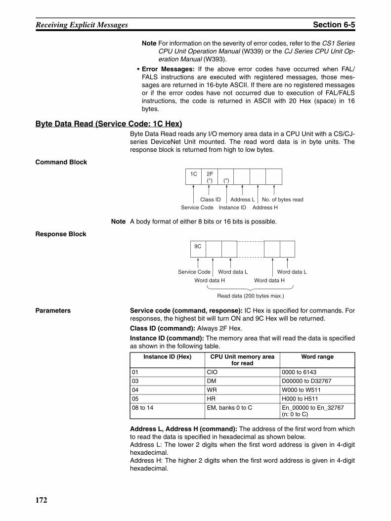
Receiving Explicit Messages Section 6-5
Note For information on the severity of error codes, refer to the CS1 SeriesCPU Unit Operation Manual (W339) or the CJ Series CPU Unit Op-eration Manual (W393).
• Error Messages: If the above error codes have occurred when FAL/FALS instructions are executed with registered messages, those mes-sages are returned in 16-byte ASCII. If there are no registered messagesor if the error codes have not occurred due to execution of FAL/FALSinstructions, the code is returned in ASCII with 20 Hex (space) in 16bytes.
Byte Data Read (Service Code: 1C Hex)Byte Data Read reads any I/O memory area data in a CPU Unit with a CS/CJ-series DeviceNet Unit mounted. The read word data is in byte units. Theresponse block is returned from high to low bytes.
Command Block
Note A body format of either 8 bits or 16 bits is possible.
Response Block
Parameters Service code (command, response): IC Hex is specified for commands. Forresponses, the highest bit will turn ON and 9C Hex will be returned.
Class ID (command): Always 2F Hex.
Instance ID (command): The memory area that will read the data is specifiedas shown in the following table.
Address L, Address H (command): The address of the first word from whichto read the data is specified in hexadecimal as shown below.Address L: The lower 2 digits when the first word address is given in 4-digithexadecimal.Address H: The higher 2 digits when the first word address is given in 4-digithexadecimal.
Class ID
Instance ID
1C 2F(*) (*)
Address L
Service Code Address H
No. of bytes read
9C
Service Code
Word data H
Word data L
Word data H
Word data L
Read data (200 bytes max.)
Instance ID (Hex) CPU Unit memory area for read
Word range
01 CIO 0000 to 6143
03 DM D00000 to D32767
04 WR W000 to W511
05 HR H000 to H511
08 to 14 EM, banks 0 to C En_00000 to En_32767 (n: 0 to C)
172

Receiving Explicit Messages Section 6-5
No of Read Bytes (command): The number of bytes of read data is specifiedin 1-byte (2-digit) hexadecimal. The range is 01 to C8 Hex (1 to 200 decimal).
No. of bytes received (response): The number of bytes received from thedestination node address (remote node) is returned in hexadecimal.
Destination node address (response): The node address of the CS/CJ-series DeviceNet Unit that returned the response is returned in hexadecimal.
Read data (response): The specified area, word, and byte data is returned inorder from word H (high byte: bits 8 to 15) to word L (low byte: bits 0 to 7). Ifan odd number is specified for the number of read bytes, the last 1 byte ofdata will be read to the high word.
Important Points The actual address L, address H, and number of read bytes that can be spec-ified depends on the model of the CPU Unit of the CS/CJ-series DeviceNetUnit and the type of memory area. Do not exceed the boundary of the dataareas for the PLC you are using.
Word Data Read (Service Code: 1D Hex)Word Data Read reads I/O memory area data in CPU Units with a CS/CJ-series DeviceNet Units. The read word data is in word units. The responseblock is returned from low to high bytes.
Command Block
Note A body format of either 8 bits or 16 bits is possible.
Response Block
Parameters Service code (command, response): ID Hex is specified for commands. Forresponses, the highest bit will turn ON and 9D Hex will be returned.
Class ID (command): Always 2F Hex.
Instance ID (command): The type of memory area that will read the data isspecified as shown in the following table.
Address L, Address H (command): The address of the first word to read thedata from is specified in hexadecimal as shown below.
Class ID
Instance ID
1C 2F(*) (*)
Address L
Service Code Address H
No. of words read
9D
Service Code
Word data L
Word data H
Word data L
Word data H
Read data (200 bytes max.)
Instance ID (Hex) CPU Unit memory area for read
Word range
01 CIO 0000 to 6143
03 DM D00000 to D32767
04 WR W000 to W511
05 HR H000 to H511
08 to 14 EM, banks 0 to C En_00000 to En_32767 (n: 0 to C)
173

Receiving Explicit Messages Section 6-5
Address L: The lower 2 digits when the first word address is given in 4-digithexadecimal.Address H: The higher 2 digits when the first word address is given in 4-digithexadecimal.
No of Read Words (command): The number of words of read data is speci-fied in 1-byte (2-digit) hexadecimal. The range is 01 to 64 Hex (1 to 100 deci-mal).
Read data (response): The specified area, word, and byte data is returned inorder from word L (low byte: bits 0 to 7) to word H (high byte: bits 8 to 15).
Important Points The actual address L, address H, and number of write data bytes that can bespecified depends on the CPU Unit of the CS/CJ-series DeviceNet Unit andthe Memory Area. Do not exceed the boundary of the data areas for the PLCyou are using.
Byte Data Write (Service Code: 1E Hex)Byte Data Write writes data to I/O memory area in CPU Units with CS/CJ-series DeviceNet Units mounted. The write word data is in byte units. Thecommand block is specified from high to low bytes, as shown in the followingdiagram.
Command Block
Note A body format of either 8 bits or 16 bits is possible.
Response Block
Parameters Service code (command, response): IE Hex is specified for commands. Forresponses, the highest bit will turn ON and 9E Hex will be returned.
Class ID (command): Always 2F Hex.
Instance ID (command): The type of memory area to which the data will bewritten is specified as shown in the following table.
Address L, Address H (command): The address of the first word to whichthe data will be written is specified in hexadecimal as shown below.
Class ID
Instance ID
1E 2F(*) (*)
Address L
Service Code Address H Word data L
Word data H
Word data L
Write data (200 bytes max.)
Word data H
Service Code
9E
Instance ID (Hex) CPU Unit memory area for write
Word range
01 CIO 0000 to 6143
03 DM D00000 to D32767
04 WR W000 to W511
05 HR H000 to H511
08 to 14 EM, banks 0 to C En_00000 to En_32767 (n: 0 to C)
174

Receiving Explicit Messages Section 6-5
Address L: The lower 2 digits when the first word address is displayed in 4-digit hexadecimal.Address H: The higher 2 digits when the first word address is displayed in 4-digit hexadecimal.
Write data (response): The specified area and write data is returned in orderfrom word H (higher byte: bits 8 to 15) to word L (lower byte: bits 0 to 7). If anodd number is specified, the last 1 byte of data will be written to word H.
Important Points The actual address L, address H, and number of write data words that can bespecified depends on the type of CPU Unit with CS/CJ-series DeviceNet Unitmounted and the type of memory area. Do not exceed the boundary of thedata areas for the PLC you are using.
Word Data Write (Service Code: 1F Hex)Word Data Write writes data to any I/O memory area in CPU Units with CS/CJ-series DeviceNet Units mounted. The write word data is in word units. Theresponse block is returned from low to high bytes.
Command Block
Note A body format of either 8 bits or 16 bits is possible.
Response Block
Parameters Service code (command, response): IF Hex is specified for commands. Forresponses, the highest bit will turn ON and 9F Hex will be returned.
Class ID (command): Always 2F Hex.
Instance ID (command): The memory area to which the data is written isspecified as shown in the following table.
Address L, Address H (command): The address of the first word to whichthe data is written is specified in hexadecimal as shown below.Address L: The lower 2 digits when the first word address is displayed in 4-digit hexadecimal.Address H: The higher 2 digits when the first word address is displayed in 4-digit hexadecimal.
Class ID
Instance ID
1F 2F(*) (*)
Address L
Service Code Address H Word data H
Word data L
Word data H
Write data (200 bytes max.)
Word data L
Service Code
9F
Instance ID (Hex) CPU Unit memory area for write
Word range
01 CIO 0000 to 6143
03 DM D00000 to D32767
04 WR W000 to W511
05 HR H000 to H511
08 to 14 EM, banks 0 to C En_00000 to En_32767 (n: 0 to C)
175

Receiving Explicit Messages Section 6-5
Write data (response): The specified area and write data is returned in orderfrom word L (lower byte: bits 0 to 7) to word H (higher byte: bits 8 to 15).
Important Points The actual address L, address H, and number of read words that can bespecified depends on the mode of CPU Unit for the CS/CJ-series DeviceNetUnit and the type of memory areas. Do not exceed the boundary of the dataareas for the PLC you are using.
176
SECTION 7Other Functions
This section describes connecting to CX-Programmer via the DeviceNet and the Memory Card backup function.
7-1 Connecting to the CX-Programmer via the DeviceNet. . . . . . . . . . . . . . . . . . 178
7-1-1 Setting Node Addresses . . . . . . . . . . . . . . . . . . . . . . . . . . . . . . . . . . 179
7-1-2 Setting the Message Monitoring Timer of the DeviceNet Unit . . . . 179
7-1-3 Setting the Frame Length when Using the CX-Programmer via
the DeviceNet . . . . . . . . . . . . . . . . . . . . . . . . . . . . . . . . . . . . . . . . . . 181
7-1-4 Response when Using the CX-Programmer via the DeviceNet . . . . 181
7-2 Memory Card Backup Functions . . . . . . . . . . . . . . . . . . . . . . . . . . . . . . . . . . 182
7-2-1 Outline of Functions . . . . . . . . . . . . . . . . . . . . . . . . . . . . . . . . . . . . . 183
7-2-2 File Names . . . . . . . . . . . . . . . . . . . . . . . . . . . . . . . . . . . . . . . . . . . . 184
7-3 Simple Backup Function . . . . . . . . . . . . . . . . . . . . . . . . . . . . . . . . . . . . . . . . . 185
7-3-1 Overview of Function . . . . . . . . . . . . . . . . . . . . . . . . . . . . . . . . . . . . 185
7-3-2 Applications . . . . . . . . . . . . . . . . . . . . . . . . . . . . . . . . . . . . . . . . . . . 185
7-3-3 Operating Methods . . . . . . . . . . . . . . . . . . . . . . . . . . . . . . . . . . . . . . 186
177
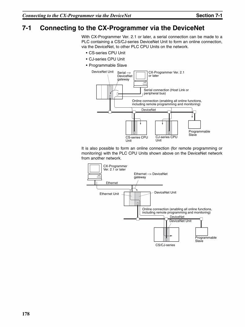
Connecting to the CX-Programmer via the DeviceNet Section 7-1
7-1 Connecting to the CX-Programmer via the DeviceNetWith CX-Programmer Ver. 2.1 or later, a serial connection can be made to aPLC containing a CS/CJ-series DeviceNet Unit to form an online connection,via the DeviceNet, to other PLC CPU Units on the network.
• CS-series CPU Unit
• CJ-series CPU Unit
• Programmable Slave
It is also possible to form an online connection (for remote programming ormonitoring) with the PLC CPU Units shown above on the DeviceNet networkfrom another network.
DeviceNet
DeviceNet Unit CX-Programmer Ver. 2.1 or later
Serial connection (Host Link or peripheral bus)
Serial --> DeviceNet gateway
Online connection (enabling all online functions, including remote programming and monitoring)
CS-series CPU Unit
CJ-series CPU Unit
Programmable Slave
DeviceNet
Ethernet
CX-Programmer Ver. 2.1 or later
Ethernet --> DeviceNet gateway
DeviceNet Unit
Online connection (enabling all online functions, including remote programming and monitoring)
DeviceNet Unit
CS/CJ-series
Programmable Slave
Ethernet Unit
178

Connecting to the CX-Programmer via the DeviceNet Section 7-1
7-1-1 Setting Node AddressesWhen the CX-Programmer is connected online, it uses FINS message com-munications. It is thus necessary to set the node address to a number otherthan 0 for DeviceNet Units mounted to the target PLC, DeviceNet Unitsmounted to a PLC which is connected by a serial connection to the CX-Pro-grammer, or DeviceNet Units mounted to a PLC relaying between networks.If a DeviceNet Unit with the address node 0 exists in the online connectionpath, connection will not be possible.
7-1-2 Setting the Message Monitoring Timer of the DeviceNet Unit When connecting the CX-Programmer via the DeviceNet, set the messagemonitoring timer inside the following DeviceNet Units to 20,000 ms (20 s).
• The DeviceNet Unit mounted to the PLC with the serial connection to theCX-Programmer.
• The DeviceNet Unit mounted to the PLC relaying between networks.
Use the Configurator to set the message monitoring timer.
Setting the Message Monitoring Timer
Use the following procedure to set the message monitoring timer.
1,2,3... 1. Select Device/Parameter/Edit and then click the Message Timer Tab.
DeviceNet
DeviceNet
Ethernet
DeviceNet Unit CX-Programmer Ver. 2.1 or later
CX-Programmer Ver. 2.1 or later
Serial connection (Host Link or peripheral bus) Ethernet Unit DeviceNet Unit
Set the message monitoring timer of this DeviceNet Unit to 20,000 ms (20 s).
Set the message monitoring timer of this DeviceNet Unit to 20,000 ms (20 s).
179

Connecting to the CX-Programmer via the DeviceNet Section 7-1
2. Double-click on the node address (#) that you want to change, or select thenode address and click on the Edit Button. A dialogue box like the one be-low will appear.
3. Input the value, then click on the OK Button.
Note To set the same value for all of the devices, select the node address-es to be set, then click on Copy to All Device.
Note 1. The default setting for the message monitoring timer is 2,000 ms (2 s). If itis used without being changed, a communications error will result when theCX-Programmer is operated. The setting range is 500 to 30,000 ms. Set inunits of ms.
2. The message monitoring timer serves as a timeout monitor for messagecommunications (both explicit and FINS). Settings can be made for eachdevice to which messages are to be sent. When the response from the tar-get device is slow, the setting value must be increased. This is often thecase when FINS messages are sent across networks, because the re-sponse time is typically slow. However, when the setting is increased, sub-sequent messages cannot be sent to the same device until it is finishedwaiting for the response.
Whereas the DeviceNet Unit monitors the message time-out with this tim-er, the CPU Unit monitors with the response monitor time set in the CMND/SEND/RECV instruction. There is thus no effect when only one of them,i.e., only the message monitoring timer or only the response monitor timein the CMND/SEND/RECV instruction, is increased or decreased. Set the
180
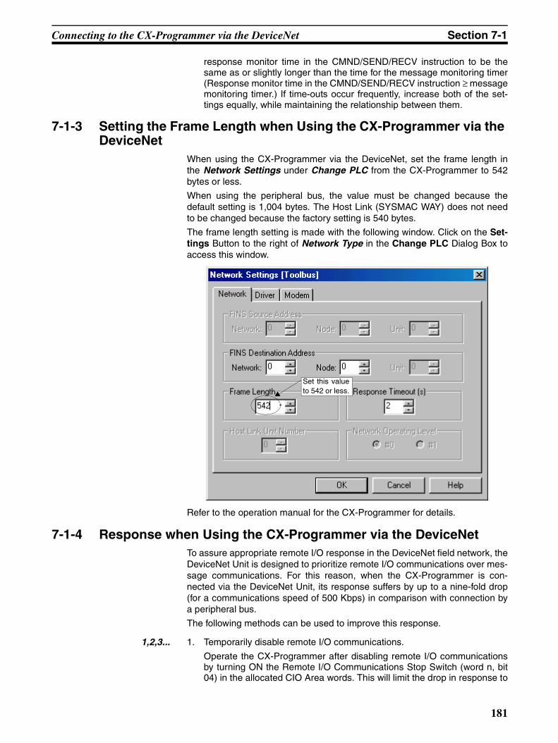
Connecting to the CX-Programmer via the DeviceNet Section 7-1
response monitor time in the CMND/SEND/RECV instruction to be thesame as or slightly longer than the time for the message monitoring timer(Response monitor time in the CMND/SEND/RECV instruction ≥ messagemonitoring timer.) If time-outs occur frequently, increase both of the set-tings equally, while maintaining the relationship between them.
7-1-3 Setting the Frame Length when Using the CX-Programmer via the DeviceNet
When using the CX-Programmer via the DeviceNet, set the frame length inthe Network Settings under Change PLC from the CX-Programmer to 542bytes or less.
When using the peripheral bus, the value must be changed because thedefault setting is 1,004 bytes. The Host Link (SYSMAC WAY) does not needto be changed because the factory setting is 540 bytes.
The frame length setting is made with the following window. Click on the Set-tings Button to the right of Network Type in the Change PLC Dialog Box toaccess this window.
Refer to the operation manual for the CX-Programmer for details.
7-1-4 Response when Using the CX-Programmer via the DeviceNetTo assure appropriate remote I/O response in the DeviceNet field network, theDeviceNet Unit is designed to prioritize remote I/O communications over mes-sage communications. For this reason, when the CX-Programmer is con-nected via the DeviceNet Unit, its response suffers by up to a nine-fold drop(for a communications speed of 500 Kbps) in comparison with connection bya peripheral bus.
The following methods can be used to improve this response.
1,2,3... 1. Temporarily disable remote I/O communications.
Operate the CX-Programmer after disabling remote I/O communicationsby turning ON the Remote I/O Communications Stop Switch (word n, bit04) in the allocated CIO Area words. This will limit the drop in response to
Set this valueto 542 or less.
181

Memory Card Backup Functions Section 7-2
a maximum of four-fold (for a communications speed of 500 Kbps) in com-parison with connection by a peripheral bus.
2. Temporarily extend the communications cycle time.
Operate the CX-Programmer after extending the cycle time in the Commu-nications Cycle Time Setup Table (word m) in the DM Area, and turning ONthe Temporary Setting Switch for Communications Cycle Time (word n, bit12).
Extending the communications cycle time 1.5 times will result in a 20%-30% improvement in response. However, whereas the CX-Programmer re-sponse will increasingly improve by extending the communications cycletime, the remote I/O communications response will suffer.
Note The CX-Programmer response decreases in accordance with decreases inthe DeviceNet communications speed. At a speed of 125 Kbps, response willsuffer by up to a twenty-fold drop in comparison with connection by a periph-eral bus.
Accordingly, a DeviceNet communications speed of 500 Kbps is recom-mended when the CX-Programmer is connected to the network via theDeviceNet Unit.
7-2 Memory Card Backup FunctionsThe DeviceNet Unit stores the following setup data in the internal non-volatilememory (EEPROM).
• Master scan lists
• Slave scan lists
• Message monitoring timer lists
• Communications cycle time settings
• Master/Slave functions enabled/disabled settings
Note Backup is possible only when scan lists are enabled.
With the CS/CJ-series DeviceNet Unit, all this setup data can be backed up toand restored from a Memory Card mounted to the CPU Unit. (See note.)
Note The data can be backed up to a Memory Card only. It cannot be backed up toa EM file.
If all setup data for a DeviceNet Unit that starts normally is saved on a Mem-ory Card, that data can be read and used when replacing DeviceNet Units,making the replacement process smooth.
Device parameter files (.dvf files) created using the Configurator can be savedfrom the computer to the Memory Card and can be restored to the DeviceNetUnit mounted to the CPU Unit. This means that setup data created using theConfigurator (scan lists and other parameters) can be downloaded toDeviceNet Units simply by taking the Memory Card to site.
182
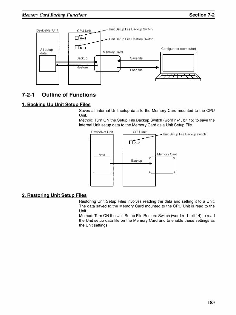
Memory Card Backup Functions Section 7-2
7-2-1 Outline of Functions
1. Backing Up Unit Setup FilesSaves all internal Unit setup data to the Memory Card mounted to the CPUUnit.Method: Turn ON the Setup File Backup Switch (word n+1, bit 15) to save theinternal Unit setup data to the Memory Card as a Unit Setup File.
2. Restoring Unit Setup FilesRestoring Unit Setup Files involves reading the data and setting it to a Unit.The data saved to the Memory Card mounted to the CPU Unit is read to theUnit.Method: Turn ON the Unit Setup File Restore Switch (word n+1, bit 14) to readthe Unit setup data file on the Memory Card and to enable these settings asthe Unit settings.
DeviceNet Unit CPU Unit
Backup
Restore
Unit Setup File Backup Switch
Unit Setup File Restore Switch
Memory Card
Save file
Load file
All setup data
Configurator (computer)
DeviceNet Unit CPU Unit
data
Backup
Memory Card
Unit Setup File Backup switch
183
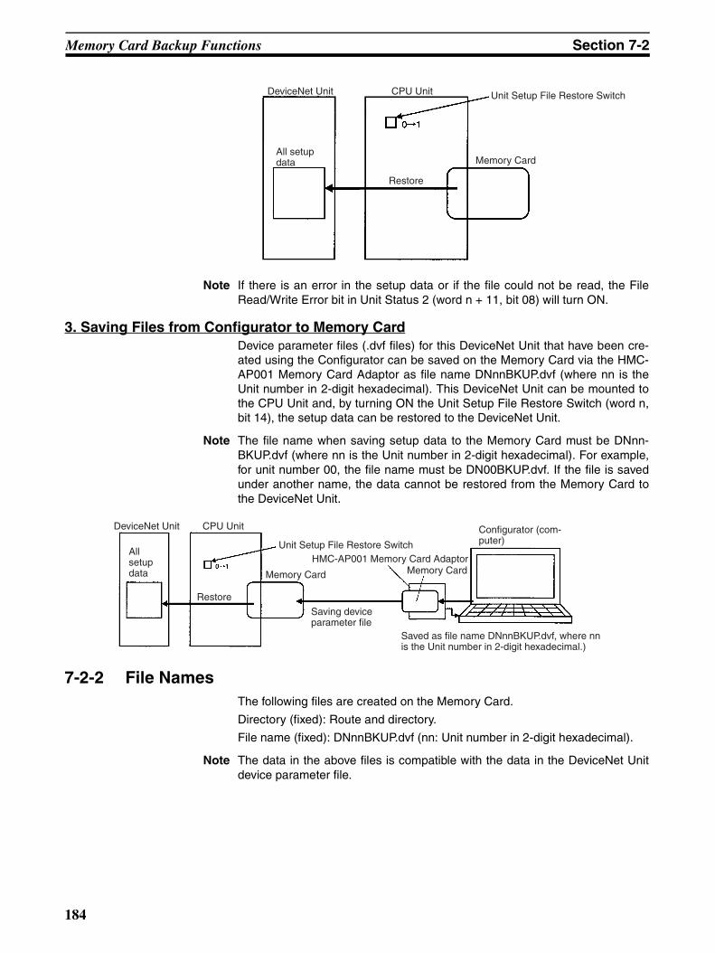
Memory Card Backup Functions Section 7-2
Note If there is an error in the setup data or if the file could not be read, the FileRead/Write Error bit in Unit Status 2 (word n + 11, bit 08) will turn ON.
3. Saving Files from Configurator to Memory CardDevice parameter files (.dvf files) for this DeviceNet Unit that have been cre-ated using the Configurator can be saved on the Memory Card via the HMC-AP001 Memory Card Adaptor as file name DNnnBKUP.dvf (where nn is theUnit number in 2-digit hexadecimal). This DeviceNet Unit can be mounted tothe CPU Unit and, by turning ON the Unit Setup File Restore Switch (word n,bit 14), the setup data can be restored to the DeviceNet Unit.
Note The file name when saving setup data to the Memory Card must be DNnn-BKUP.dvf (where nn is the Unit number in 2-digit hexadecimal). For example,for unit number 00, the file name must be DN00BKUP.dvf. If the file is savedunder another name, the data cannot be restored from the Memory Card tothe DeviceNet Unit.
7-2-2 File NamesThe following files are created on the Memory Card.
Directory (fixed): Route and directory.
File name (fixed): DNnnBKUP.dvf (nn: Unit number in 2-digit hexadecimal).
Note The data in the above files is compatible with the data in the DeviceNet Unitdevice parameter file.
Unit Setup File Restore Switch
Memory Card
DeviceNet Unit CPU Unit
Restore
All setup data
DeviceNet Unit
All setup data
CPU Unit
Restore
Unit Setup File Restore Switch
Memory Card
Saved as file name DNnnBKUP.dvf, where nn is the Unit number in 2-digit hexadecimal.)
Configurator (com-puter)
Memory CardHMC-AP001 Memory Card Adaptor
Saving device parameter file
184
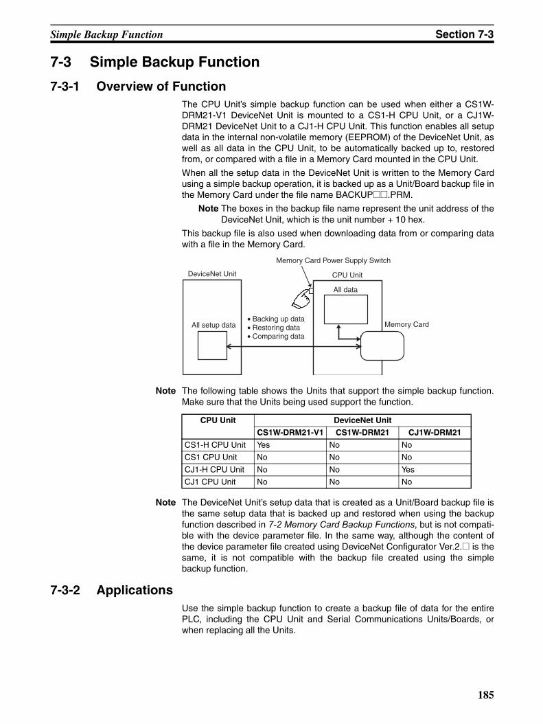
Simple Backup Function Section 7-3
7-3 Simple Backup Function
7-3-1 Overview of FunctionThe CPU Unit’s simple backup function can be used when either a CS1W-DRM21-V1 DeviceNet Unit is mounted to a CS1-H CPU Unit, or a CJ1W-DRM21 DeviceNet Unit to a CJ1-H CPU Unit. This function enables all setupdata in the internal non-volatile memory (EEPROM) of the DeviceNet Unit, aswell as all data in the CPU Unit, to be automatically backed up to, restoredfrom, or compared with a file in a Memory Card mounted in the CPU Unit.
When all the setup data in the DeviceNet Unit is written to the Memory Cardusing a simple backup operation, it is backed up as a Unit/Board backup file inthe Memory Card under the file name BACKUP@@.PRM.
Note The boxes in the backup file name represent the unit address of theDeviceNet Unit, which is the unit number + 10 hex.
This backup file is also used when downloading data from or comparing datawith a file in the Memory Card.
Note The following table shows the Units that support the simple backup function.Make sure that the Units being used support the function.
Note The DeviceNet Unit’s setup data that is created as a Unit/Board backup file isthe same setup data that is backed up and restored when using the backupfunction described in 7-2 Memory Card Backup Functions, but is not compati-ble with the device parameter file. In the same way, although the content ofthe device parameter file created using DeviceNet Configurator Ver.2.@ is thesame, it is not compatible with the backup file created using the simplebackup function.
7-3-2 ApplicationsUse the simple backup function to create a backup file of data for the entirePLC, including the CPU Unit and Serial Communications Units/Boards, orwhen replacing all the Units.
• Backing up data• Restoring data• Comparing data
DeviceNet Unit
Memory Card Power Supply Switch
CPU Unit
All data
All setup data Memory Card
CPU Unit DeviceNet Unit
CS1W-DRM21-V1 CS1W-DRM21 CJ1W-DRM21
CS1-H CPU Unit Yes No No
CS1 CPU Unit No No No
CJ1-H CPU Unit No No Yes
CJ1 CPU Unit No No No
185
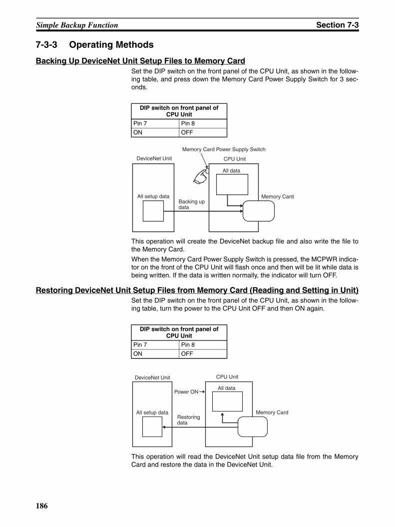
Simple Backup Function Section 7-3
7-3-3 Operating Methods
Backing Up DeviceNet Unit Setup Files to Memory CardSet the DIP switch on the front panel of the CPU Unit, as shown in the follow-ing table, and press down the Memory Card Power Supply Switch for 3 sec-onds.
This operation will create the DeviceNet backup file and also write the file tothe Memory Card.
When the Memory Card Power Supply Switch is pressed, the MCPWR indica-tor on the front of the CPU Unit will flash once and then will be lit while data isbeing written. If the data is written normally, the indicator will turn OFF.
Restoring DeviceNet Unit Setup Files from Memory Card (Reading and Setting in Unit)Set the DIP switch on the front panel of the CPU Unit, as shown in the follow-ing table, turn the power to the CPU Unit OFF and then ON again.
This operation will read the DeviceNet Unit setup data file from the MemoryCard and restore the data in the DeviceNet Unit.
DIP switch on front panel of CPU Unit
Pin 7 Pin 8
ON OFF
DeviceNet Unit
Memory Card Power Supply Switch
CPU Unit
All data
All setup data Memory CardBacking up data
DIP switch on front panel of CPU Unit
Pin 7 Pin 8
ON OFF
DeviceNet Unit CPU Unit
All data
All setup data Memory Card
Power ON
Restoring data
186
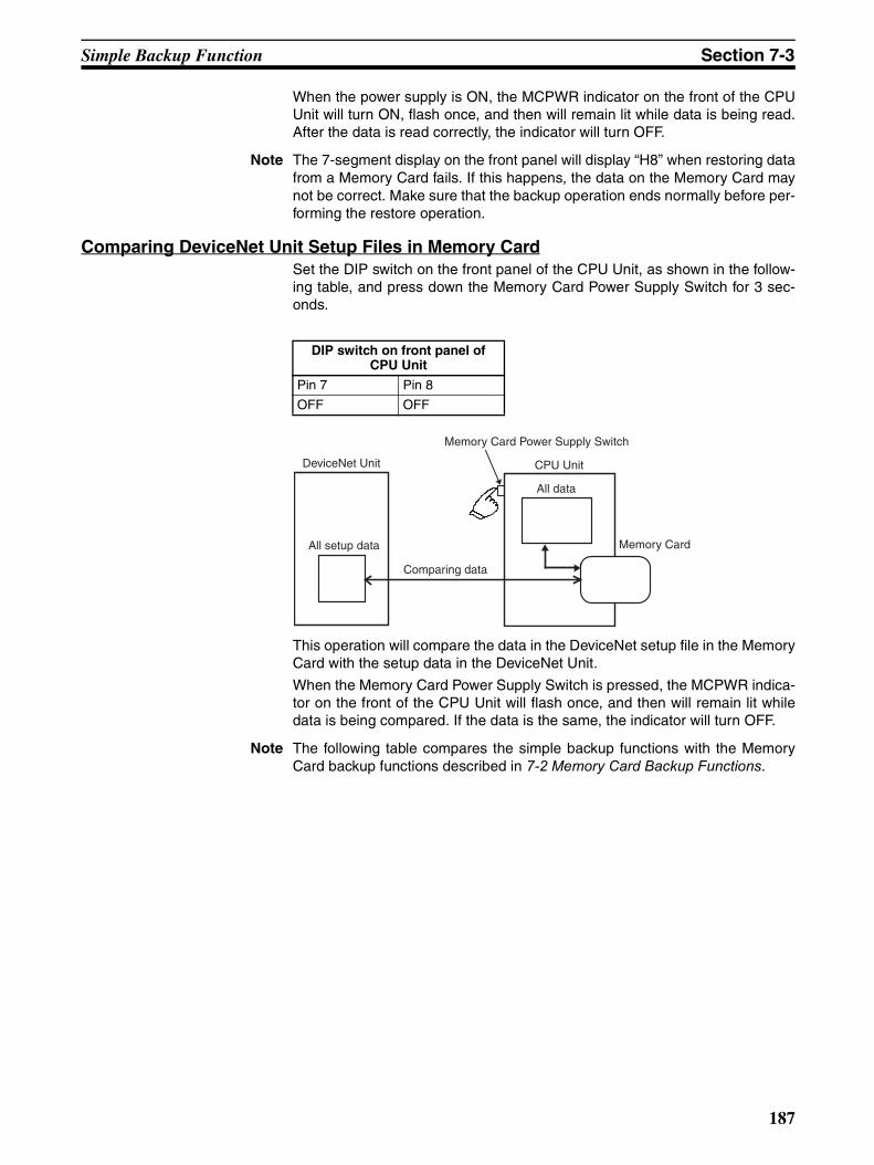
Simple Backup Function Section 7-3
When the power supply is ON, the MCPWR indicator on the front of the CPUUnit will turn ON, flash once, and then will remain lit while data is being read.After the data is read correctly, the indicator will turn OFF.
Note The 7-segment display on the front panel will display “H8” when restoring datafrom a Memory Card fails. If this happens, the data on the Memory Card maynot be correct. Make sure that the backup operation ends normally before per-forming the restore operation.
Comparing DeviceNet Unit Setup Files in Memory CardSet the DIP switch on the front panel of the CPU Unit, as shown in the follow-ing table, and press down the Memory Card Power Supply Switch for 3 sec-onds.
This operation will compare the data in the DeviceNet setup file in the MemoryCard with the setup data in the DeviceNet Unit.
When the Memory Card Power Supply Switch is pressed, the MCPWR indica-tor on the front of the CPU Unit will flash once, and then will remain lit whiledata is being compared. If the data is the same, the indicator will turn OFF.
Note The following table compares the simple backup functions with the MemoryCard backup functions described in 7-2 Memory Card Backup Functions.
DIP switch on front panel of CPU Unit
Pin 7 Pin 8
OFF OFF
DeviceNet Unit
Memory Card Power Supply Switch
CPU Unit
All data
All setup data Memory Card
Comparing data
187
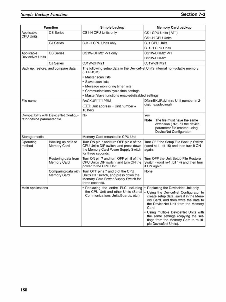
Simple Backup Function Section 7-3
Function Simple backup Memory Card backup
Applicable CPU Units
CS Series CS1-H CPU Units only CS1 CPU Units (-V@)
CS1-H CPU Units
CJ Series CJ1-H CPU Units only CJ1 CPU Units
CJ1-H CPU Units
Applicable DeviceNet Units
CS Series CS1W-DRM21-V1 only CS1W-DRM21-V1CS1W-DRM21
CJ Series CJ1W-DRM21 CJ1W-DRM21
Back up, restore, and compare data The following setup data in the DeviceNet Unit’s internal non-volatile memory (EEPROM):• Master scan lists• Slave scan lists• Message monitoring timer lists• Communications cycle time settings• Master/slave functions enabled/disabled settings
File name BACKUP@@.PRM
(@@: Unit address = Unit number + 10 hex)
DNnnBKUP.dvf (nn: Unit number in 2-digit hexadecimal)
Compatibility with DeviceNet Configu-rator device parameter file
No Yes
Note The file must have the same extension (.dvf) as the device parameter file created using DeviceNet Configurator.
Storage media Memory Card mounted in CPU Unit
Operating method
Backing up data to Memory Card
Turn ON pin 7 and turn OFF pin 8 of the CPU Unit’s DIP switch, and press down the Memory Card Power Supply Switch for three seconds.
Turn OFF the Setup File Backup Switch (word n+1, bit 15) and then turn it ON again.
Restoring data from Memory Card
Turn ON pin 7 and turn OFF pin 8 of the CPU Unit’s DIP switch, and turn ON the power to the CPU Unit.
Turn OFF the Unit Setup File Restore Switch (word n+1, bit 14) and then turn it ON again.
Comparing data with Memory Card
Turn OFF pins 7 and 8 of the CPU Unit’s DIP switch, and press down the Memory Card Power Supply Switch for three seconds.
None
Main applications • Replacing the entire PLC includingthe CPU Unit and other Units (SerialCommunications Units/Boards, etc.)
• Replacing the DeviceNet Unit only.• Using the DeviceNet Configurator to
create setup data, save it in the Mem-ory Card, and then write the data tothe DeviceNet Unit from the MemoryCard.
• Using multiple DeviceNet Units withthe same settings (copying the set-tings from the Memory Card to multi-ple DeviceNet Units).
188

SECTION 8Communications Timing
This section describes the time required for remote I/O communications and message communications.
8-1 Remote I/O Communications Characteristics. . . . . . . . . . . . . . . . . . . . . . . . . 190
8-1-1 Communications Cycle Time and Refresh Time . . . . . . . . . . . . . . . 190
8-1-2 I/O Response Time . . . . . . . . . . . . . . . . . . . . . . . . . . . . . . . . . . . . . . 193
8-1-3 More than One Master in Network. . . . . . . . . . . . . . . . . . . . . . . . . . 195
8-1-4 System Startup Time. . . . . . . . . . . . . . . . . . . . . . . . . . . . . . . . . . . . . 195
8-2 Message Communications . . . . . . . . . . . . . . . . . . . . . . . . . . . . . . . . . . . . . . . 196
8-2-1 Message Communications Time. . . . . . . . . . . . . . . . . . . . . . . . . . . . 196
8-2-2 Calculating the Maximum Message Response Time . . . . . . . . . . . . 197
189

Remote I/O Communications Characteristics Section 8-1
8-1 Remote I/O Communications CharacteristicsThis section describes the characteristics of remote I/O communicationswhen the DeviceNet Unit is used as a master in combination with OMRON’sslaves. Use this section for reference when planning operations that requireprecise I/O timing.
The equations provided here are valid under the following conditions:
1,2,3... 1. The DeviceNet Unit is operating with the scan list enabled.
2. All of the required Slaves are participating in communications.
3. No errors are being indicated at the DeviceNet Unit
4. Messages aren’t being produced in the Network (from another company’sconfigurator, for example).
Note The values provided by these equations may not be accurate if another com-pany’s Master or Slave is being used in the Network.
8-1-1 Communications Cycle Time and Refresh TimeThis section explains the communications cycle time, communications timeper slave, and refresh time required for calculating processing time by theDeviceNet Unit.
Communications Cycle TimeThe communications cycle time is the time from the completion of a Slave’sremote I/O communications processing until remote I/O communications withthe same Slave are processed again. The communications cycle time is usedto calculate the maximum I/O response time.
The communications cycle time depends on the number of Masters in theNetwork and on whether or not message communications are being per-formed. The following explanation is for a network with one Master. For net-works with several Masters, refer to More than One Master in Network in thefollowing section.
Communications Cycle Time Graph
The following graph shows communications cycle time for the number ofslaves when there are both 16-point output and 16-point input slaves.Inputs: Bit strobe, Outputs: Poll connection
Number of Slaves
: Communications cycle time: 500 kbps (ms)
: Communications cycle time: 250 kbps (ms)
: Communications cycle time: 125 kbps (ms)
Com
mun
icat
ions
cyc
le ti
me
(ms)
190
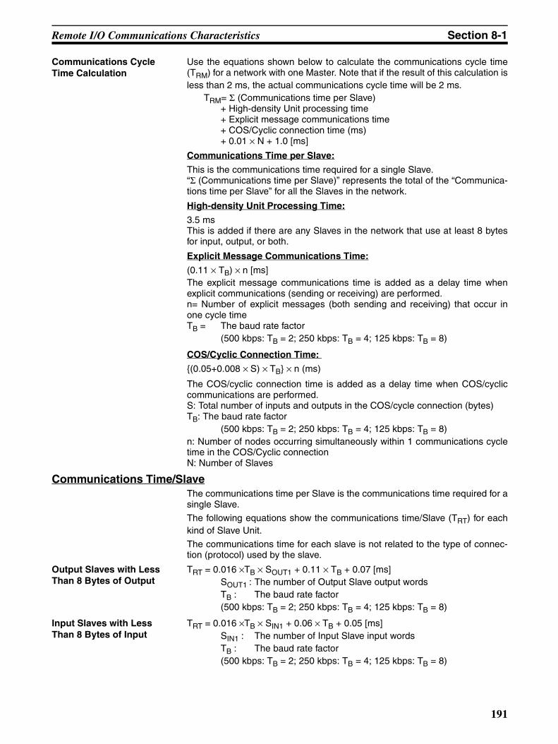
Remote I/O Communications Characteristics Section 8-1
Communications Cycle Time Calculation
Use the equations shown below to calculate the communications cycle time(TRM) for a network with one Master. Note that if the result of this calculation isless than 2 ms, the actual communications cycle time will be 2 ms.
TRM= Σ (Communications time per Slave)+ High-density Unit processing time+ Explicit message communications time+ COS/Cyclic connection time (ms)+ 0.01 × N + 1.0 [ms]
Communications Time per Slave:
This is the communications time required for a single Slave.“Σ (Communications time per Slave)” represents the total of the “Communica-tions time per Slave” for all the Slaves in the network.
High-density Unit Processing Time:
3.5 msThis is added if there are any Slaves in the network that use at least 8 bytesfor input, output, or both.
Explicit Message Communications Time:
(0.11 × TB) × n [ms]The explicit message communications time is added as a delay time whenexplicit communications (sending or receiving) are performed.n= Number of explicit messages (both sending and receiving) that occur inone cycle timeTB = The baud rate factor
(500 kbps: TB = 2; 250 kbps: TB = 4; 125 kbps: TB = 8)
COS/Cyclic Connection Time:
(0.05+0.008 × S) × TB × n (ms)
The COS/cyclic connection time is added as a delay time when COS/cycliccommunications are performed.S: Total number of inputs and outputs in the COS/cycle connection (bytes) TB: The baud rate factor
(500 kbps: TB = 2; 250 kbps: TB = 4; 125 kbps: TB = 8)n: Number of nodes occurring simultaneously within 1 communications cycletime in the COS/Cyclic connectionN: Number of Slaves
Communications Time/SlaveThe communications time per Slave is the communications time required for asingle Slave.
The following equations show the communications time/Slave (TRT) for eachkind of Slave Unit.
The communications time for each slave is not related to the type of connec-tion (protocol) used by the slave.
Output Slaves with Less Than 8 Bytes of Output
TRT = 0.016 ×TB × SOUT1 + 0.11 × TB + 0.07 [ms]SOUT1 : The number of Output Slave output wordsTB : The baud rate factor(500 kbps: TB = 2; 250 kbps: TB = 4; 125 kbps: TB = 8)
Input Slaves with Less Than 8 Bytes of Input
TRT = 0.016 ×TB × SIN1 + 0.06 × TB + 0.05 [ms]SIN1 : The number of Input Slave input wordsTB : The baud rate factor(500 kbps: TB = 2; 250 kbps: TB = 4; 125 kbps: TB = 8)
191
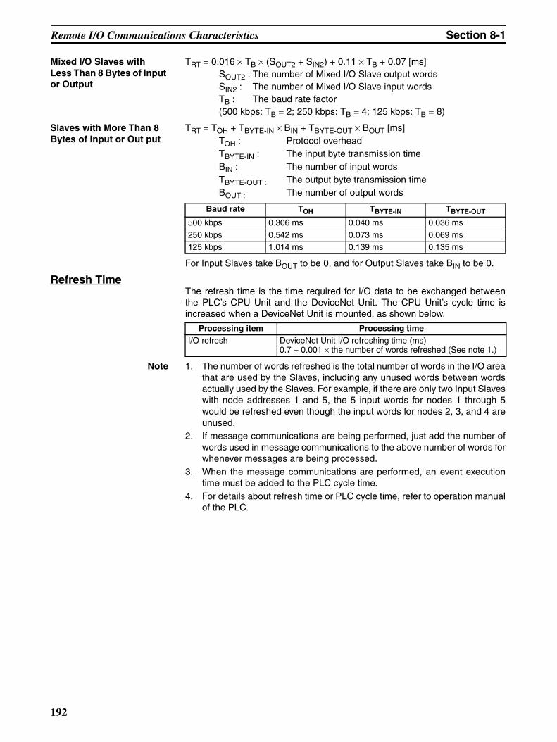
Remote I/O Communications Characteristics Section 8-1
Mixed I/O Slaves with Less Than 8 Bytes of Input or Output
TRT = 0.016 × TB × (SOUT2 + SIN2) + 0.11 × TB + 0.07 [ms]SOUT2 : The number of Mixed I/O Slave output wordsSIN2 : The number of Mixed I/O Slave input wordsTB : The baud rate factor(500 kbps: TB = 2; 250 kbps: TB = 4; 125 kbps: TB = 8)
Slaves with More Than 8 Bytes of Input or Out put
TRT = TOH + TBYTE-IN × BIN + TBYTE-OUT × BOUT [ms]TOH : Protocol overheadTBYTE-IN : The input byte transmission timeBIN : The number of input wordsTBYTE-OUT : The output byte transmission timeBOUT : The number of output words
For Input Slaves take BOUT to be 0, and for Output Slaves take BIN to be 0.
Refresh TimeThe refresh time is the time required for I/O data to be exchanged betweenthe PLC’s CPU Unit and the DeviceNet Unit. The CPU Unit’s cycle time isincreased when a DeviceNet Unit is mounted, as shown below.
Note 1. The number of words refreshed is the total number of words in the I/O areathat are used by the Slaves, including any unused words between wordsactually used by the Slaves. For example, if there are only two Input Slaveswith node addresses 1 and 5, the 5 input words for nodes 1 through 5would be refreshed even though the input words for nodes 2, 3, and 4 areunused.
2. If message communications are being performed, just add the number ofwords used in message communications to the above number of words forwhenever messages are being processed.
3. When the message communications are performed, an event executiontime must be added to the PLC cycle time.
4. For details about refresh time or PLC cycle time, refer to operation manualof the PLC.
Baud rate TOH TBYTE-IN TBYTE-OUT
500 kbps 0.306 ms 0.040 ms 0.036 ms
250 kbps 0.542 ms 0.073 ms 0.069 ms125 kbps 1.014 ms 0.139 ms 0.135 ms
Processing item Processing timeI/O refresh DeviceNet Unit I/O refreshing time (ms)
0.7 + 0.001 × the number of words refreshed (See note 1.)
192
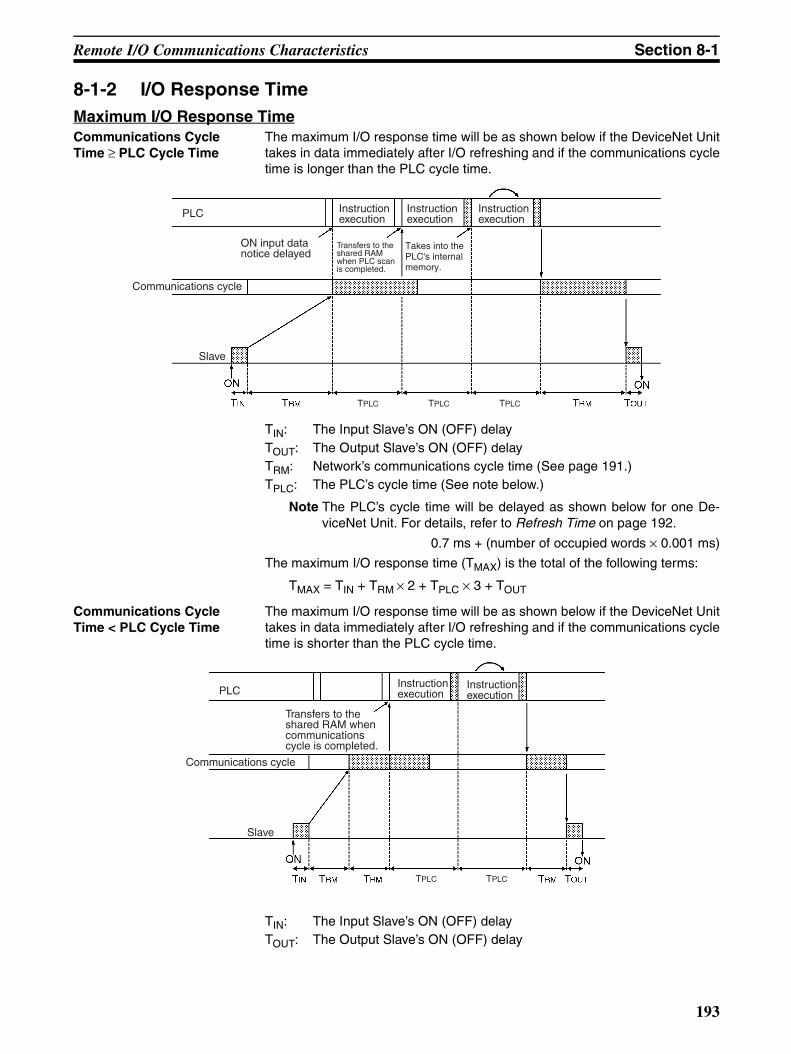
Remote I/O Communications Characteristics Section 8-1
8-1-2 I/O Response TimeMaximum I/O Response TimeCommunications Cycle Time ≥ PLC Cycle Time
The maximum I/O response time will be as shown below if the DeviceNet Unittakes in data immediately after I/O refreshing and if the communications cycletime is longer than the PLC cycle time.
TIN: The Input Slave’s ON (OFF) delayTOUT: The Output Slave’s ON (OFF) delayTRM: Network’s communications cycle time (See page 191.)TPLC: The PLC’s cycle time (See note below.)
Note The PLC’s cycle time will be delayed as shown below for one De-viceNet Unit. For details, refer to Refresh Time on page 192.
0.7 ms + (number of occupied words × 0.001 ms)
The maximum I/O response time (TMAX) is the total of the following terms:
TMAX = TIN + TRM × 2 + TPLC × 3 + TOUT
Communications Cycle Time < PLC Cycle Time
The maximum I/O response time will be as shown below if the DeviceNet Unittakes in data immediately after I/O refreshing and if the communications cycletime is shorter than the PLC cycle time.
TIN: The Input Slave’s ON (OFF) delayTOUT: The Output Slave’s ON (OFF) delay
ON input data notice delayed
Communications cycle
Instruction execution
Instruction execution
Instruction executionPLC
Transfers to the shared RAM when PLC scan is completed.
Slave
TPLC TPLC TPLC
Takes into the PLC's internal memory.
Communications cycle
Instruction execution
Instruction executionPLC
Transfers to the shared RAM when communications cycle is completed.
Slave
TPLC TPLC
193
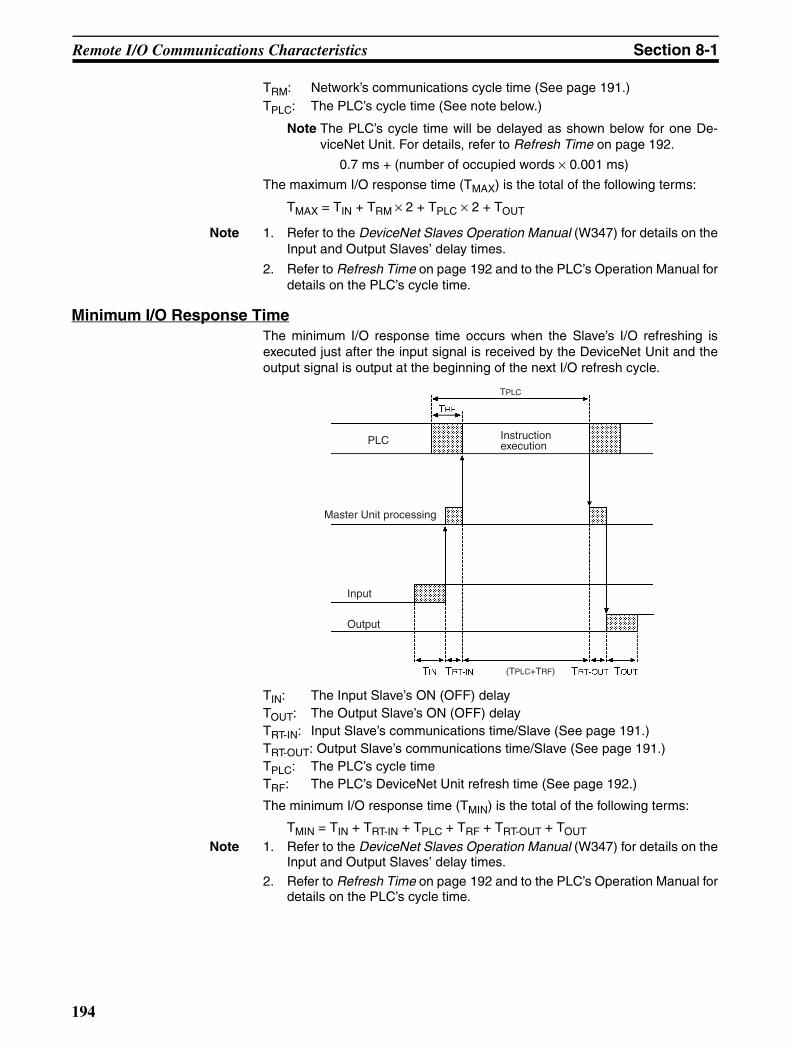
Remote I/O Communications Characteristics Section 8-1
TRM: Network’s communications cycle time (See page 191.)TPLC: The PLC’s cycle time (See note below.)
Note The PLC’s cycle time will be delayed as shown below for one De-viceNet Unit. For details, refer to Refresh Time on page 192.
0.7 ms + (number of occupied words × 0.001 ms)
The maximum I/O response time (TMAX) is the total of the following terms:
TMAX = TIN + TRM × 2 + TPLC × 2 + TOUT
Note 1. Refer to the DeviceNet Slaves Operation Manual (W347) for details on theInput and Output Slaves’ delay times.
2. Refer to Refresh Time on page 192 and to the PLC’s Operation Manual fordetails on the PLC’s cycle time.
Minimum I/O Response TimeThe minimum I/O response time occurs when the Slave’s I/O refreshing isexecuted just after the input signal is received by the DeviceNet Unit and theoutput signal is output at the beginning of the next I/O refresh cycle.
TIN: The Input Slave’s ON (OFF) delayTOUT: The Output Slave’s ON (OFF) delayTRT-IN: Input Slave’s communications time/Slave (See page 191.)TRT-OUT: Output Slave’s communications time/Slave (See page 191.)TPLC: The PLC’s cycle timeTRF: The PLC’s DeviceNet Unit refresh time (See page 192.)
The minimum I/O response time (TMIN) is the total of the following terms:
TMIN = TIN + TRT-IN + TPLC + TRF + TRT-OUT + TOUT
Note 1. Refer to the DeviceNet Slaves Operation Manual (W347) for details on theInput and Output Slaves’ delay times.
2. Refer to Refresh Time on page 192 and to the PLC’s Operation Manual fordetails on the PLC’s cycle time.
Instruction executionPLC
Master Unit processing
Output
Input
(TPLC+TRF)
TPLC
194
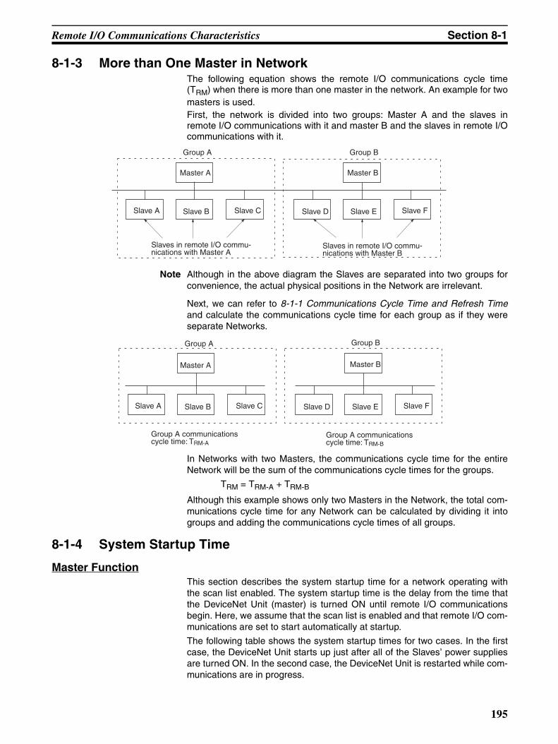
Remote I/O Communications Characteristics Section 8-1
8-1-3 More than One Master in NetworkThe following equation shows the remote I/O communications cycle time(TRM) when there is more than one master in the network. An example for twomasters is used.First, the network is divided into two groups: Master A and the slaves inremote I/O communications with it and master B and the slaves in remote I/Ocommunications with it.
Note Although in the above diagram the Slaves are separated into two groups forconvenience, the actual physical positions in the Network are irrelevant.
Next, we can refer to 8-1-1 Communications Cycle Time and Refresh Timeand calculate the communications cycle time for each group as if they wereseparate Networks.
In Networks with two Masters, the communications cycle time for the entireNetwork will be the sum of the communications cycle times for the groups.
TRM = TRM-A + TRM-B
Although this example shows only two Masters in the Network, the total com-munications cycle time for any Network can be calculated by dividing it intogroups and adding the communications cycle times of all groups.
8-1-4 System Startup Time
Master FunctionThis section describes the system startup time for a network operating withthe scan list enabled. The system startup time is the delay from the time thatthe DeviceNet Unit (master) is turned ON until remote I/O communicationsbegin. Here, we assume that the scan list is enabled and that remote I/O com-munications are set to start automatically at startup.
The following table shows the system startup times for two cases. In the firstcase, the DeviceNet Unit starts up just after all of the Slaves’ power suppliesare turned ON. In the second case, the DeviceNet Unit is restarted while com-munications are in progress.
Group A
Master A
Slave A Slave B Slave C
Slaves in remote I/O commu-nications with Master A
Group B
Master B
Slave D Slave E Slave F
Slaves in remote I/O commu-nications with Master B
Master A
Group A communications cycle time: TRM-A
Group A communications cycle time: TRM-B
Group A
Slave A Slave B Slave C
Group B
Master B
Slave D Slave E Slave F
195
Message Communications Section 8-2
Program Example As shown in the preceding table, it takes time for DeviceNet communicationsto start up. This programming uses flags in the Master status area to preventsthe Slaves’ I/O processing from being performed until remote I/O communica-tions start up.
This programming is for a DeviceNet Unit with a unit number of 00.
Note Refer to 3-2 Allocated CIO Area Words for details on the Master Status Area.
Slave FunctionIt takes approximately four seconds from the time that the Devicenet Unit isturned ON or restarted as a slave until remote I/O communications with themaster begin.
8-2 Message Communications8-2-1 Message Communications Time
The message communications time is the time required from the time a Mas-ter Unit starts to send a message over the Network to another node until theMaster Unit completes sending the message (data for SEND(192)/RECV(193) and FINS commands for CMND(194)/IOWR).The following equation can be used to compute the approximate messagecommunications time.Message communications time =
Communications cycle time x ((No. of message bytes + 15) ÷ 6 + 1)No. of message bytes: No. of data bytes following the FINS command code
The communications cycle time depends on whether or not remote I/O com-munications are being used.
Message Communications Only (No Remote I/O Communications)The following equation can be used to compute the message communicationstime when remote I/O communications are not being used.Communications cycle time =
2 (see note) + 0.11 × TB + 0.6 [ms]
Case Slave’s indicator status System startup time
The Master is started just after Slave startup.
The NS indicator is OFF or flashing green. 5 seconds
Just the Master is restarted.
The NS indicator is flashes red while the Mas-ter is OFF.
7 seconds
Just the Slaves are restarted.
--- 9 seconds
Unit Error(n+10, bit 00)
Remote I/O Communications
(n+12, bit 15)Slaves' I/O processing
151215
151000
196
Message Communications Section 8-2
TB : The baud rate factor(500 kbps: TB = 2; 250 kbps: TB = 4; 125 kbps: TB = 8)
Note The communications cycle time will be 2 ms even if remote I/O communica-tions are not being used.
Remote I/O and Message CommunicationsPerforming message communications in addition to remote I/O communica-tions will increase the message communications time.
Communications cycle time=Communications cycle time for remote I/O communications only+ 0.11 × TB + 0.6 [ms]
TB : The baud rate factor(500 kbps: TB = 2; 250 kbps: TB = 4; 125 kbps: TB = 8) (Varies depending on the baud rate.)
Note 1. If the CPU Unit attempts to send another message or receives a messagefrom another node within the message communications time, the secondmessage or the message being received from another node may be de-stroyed. Never execute a second communications instruction before themessage communications time has elapsed and never send messages toany one node at intervals less than the message communications time.
2. If send or receive messages are destroyed, error records will be placed inthe error history of the Master Unit. If an error occurs, read the error historyusing the FINS command or monitor the error history from the Configura-tor.
3. The above equations can be used to find the approximate message com-munications time, but this is a typical time, not the maximum time. Themessage communications time will vary depending on the frequency ofmessage communications, the load on the remote node, the communica-tions cycle time, and other factors. For any one Master Unit, the messagecommunications time can be greatly increased due to heavy loads and theuser program must be written to allow for this.
8-2-2 Calculating the Maximum Message Response TimeThe message response time is the time required from the time a DeviceNetUnit starts to receive an I/O memory read request message (BYTE DATAREAD explicit message) until the DeviceNet Unit completes sending theresponse message to the client.The message response times described below are based on the followingconditions:
1,2,3... 1. Only one DeviceNet Unit is mounted.
2. The I/O memory read request is returned from CS/CJ-series PLC in twocycle time.
3. Baud rate: 500 Kbps
4. Communications cycle time: 3 ms (no remote I/O communications)
5. PLC’s cycle time: 10 ms
6. DeviceNet Unit’s refresh time: 2 ms (See note.)
Note The PLC’s cycle time will be delayed as shown below for one De-viceNet Unit. For details, refer to Refresh Time on page 192.
0.7 ms + (number of occupied words × 0.001 ms)
197
Message Communications Section 8-2
Request from One Client (BYTE DATA READ)
Shown below is the response time required to return data for 100 words.
• BYTE DATA READ request sending time: TBRSDeviceNet header (4 bytes) + Parameters (3 bytes) = 7 bytes (no frag-ment)Therefore, TBRS = 1 communications cycle time (TRM) = 3 ms
• PLC’s processing time: TPC x 2TPLC x 2 = PLC’s cycle time x 2 = 10 x 2 = 20 ms
• BYTE DATA READ response receiving time: TBRRDeviceNet header (3 bytes) + Number of words to be read x 2 = 203 bytesTherefore, TBRR = 1 + 203 bytes/6 communications cycle time = 35 com-munications cycle time
• DeviceNet Unit refresh time: TRF = 2 ms
The message response time will be as follows:
= TRM + TPLC x 2 + TRM x 35 + TRF x 2 =3+20+105+4= 132 ms
Shown below is the response time required to return data for 100 words to 8clients.
• BYTE DATA READ request sending time: TBRS
DeviceNet header (4 bytes) + Parameters (3 bytes) = 7 bytes (no frag-ment)Therefore, TBRS = 1 communications cycle time (TRM) = 3 ms
• PLC’s processing time: TPLC x 6 + TPLC x 2 = TPLC x 8The following time is required to process data with other clients before thePLC starts processing.7 other clients/2 = Approximately cycle time x 3If one processing requires twice the cycle time, the time will be as follows:
Cycle time x 3 x 2 = Cycle time x 6PLC’s processing time: TPLC x 2 = Cycle time x 2Total time will be as follows:
Cycle time x 8
PLCInstruction execution
Instruction execution
BYTE DATA READ processing time:PLC's cycle time x 2
Shared memory
DeviceNet internal buffer
Communications cycle
Client
Read request
Read result
TPLC TPLC
198
Message Communications Section 8-2
• BYTE DATA READ response receiving time: TBRRDeviceNet header (3 bytes) + Number of words to be read x 2 = 203 bytesTherefore, TBRR = 1 + 203 bytes/6 communications cycle time = 35 com-munications cycle time
• DeviceNet Unit refresh time: TRF = 2 ms
The message response time will be as follows:
= TRM + TPLC x 8 + TRM x 35 + TRF x 2 x 8 =3+80+105+32= 220 ms
Note The above equations can be used to find the approximate message responsetime, but this is the typical time, not the maximum time. The messageresponse time will vary depending on the frequency of message communica-tions, the load on the remote node, the communications cycle time, and otherfactors. For any one DeviceNet Unit, the message communications time canbe greatly increased due to heavy loads and the user program must be writtento allow for this.
199

Message Communications Section 8-2
200
SECTION 9Troubleshooting and Maintenance
This section describes error processing, periodic maintenance operations, and troubleshooting procedures needed to keepthe DeviceNet network operating properly. We recommend reading through the error processing procedures beforeoperation so that operating errors can be identified and corrected more quickly.
9-1 Troubleshooting with the DeviceNet Unit Indicators . . . . . . . . . . . . . . . . . . . 202
9-1-1 Determining Operating Status from the Indicators. . . . . . . . . . . . . . 202
9-1-2 Troubleshooting Errors Occurring in the DeviceNet Unit . . . . . . . . 203
9-2 Error Log Functions . . . . . . . . . . . . . . . . . . . . . . . . . . . . . . . . . . . . . . . . . . . . 220
9-2-1 Error Log Table. . . . . . . . . . . . . . . . . . . . . . . . . . . . . . . . . . . . . . . . . 220
9-2-2 Error Codes and Detail Codes . . . . . . . . . . . . . . . . . . . . . . . . . . . . . 221
9-3 Troubleshooting . . . . . . . . . . . . . . . . . . . . . . . . . . . . . . . . . . . . . . . . . . . . . . . 224
9-3-1 CPU Unit’s ERR/ALM Indicator Lit or Flashing. . . . . . . . . . . . . . . 224
9-3-2 Remote I/O Communications Disabled . . . . . . . . . . . . . . . . . . . . . . 224
9-3-3 I/O Link Problems . . . . . . . . . . . . . . . . . . . . . . . . . . . . . . . . . . . . . . 225
9-3-4 Communications Error Operation Settings. . . . . . . . . . . . . . . . . . . . 226
9-3-5 Scan List Problems . . . . . . . . . . . . . . . . . . . . . . . . . . . . . . . . . . . . . . 226
9-4 Maintenance and Replacement . . . . . . . . . . . . . . . . . . . . . . . . . . . . . . . . . . . . 227
9-4-1 Cleaning . . . . . . . . . . . . . . . . . . . . . . . . . . . . . . . . . . . . . . . . . . . . . . 227
9-4-2 Inspection . . . . . . . . . . . . . . . . . . . . . . . . . . . . . . . . . . . . . . . . . . . . . 227
9-4-3 Replacing Faulty Units . . . . . . . . . . . . . . . . . . . . . . . . . . . . . . . . . . . 228
201

Troubleshooting with the DeviceNet Unit Indicators Section 9-1
9-1 Troubleshooting with the DeviceNet Unit Indicators
9-1-1 Determining Operating Status from the IndicatorsThe following table shows the status of the MS and NS indicators and the 7-segment display during normal operation.
Indicator status Network/Unit status Comments
MS NS 7-segment
OFF OFF OFF Initializing with PLC Initialization processing with the PLC is in progress.
Restart the DeviceNet Unit if this status continues for an extended period of time. Replace the CPU Unit and/or DeviceNet Unit if the problem is not cor-rected by restarting.
ON (green)
OFF Master’s node address (flashing)
Checking for node address duplication
The node address duplication check is performed after initialization.
ON (green)
Flashing (green)
Master’s node address (flashing)
Waiting for remote I/O com-munications
The Unit will have this status until remote I/O com-munications are performed with the master or slave function. (When both functions are operating, the Unit will have this status until remote I/O communi-cations are performed with either function.)
Master’s node address
Waiting for message commu-nications connection
The Unit will have this status when both the master and slave functions are disabled and the Unit is waiting for a connection by message communica-tions.
ON (green)
ON (green)
Master’s node address
Remote I/O or message com-munications in progress.
This is the normal display when the master and/or slave is active.
ON (green)
ON (green)
- - (flashing) Scan list operation in progress.
The scan list is being saved in flash memory or the scan list is being cleared.
202

Troubleshooting with the DeviceNet Unit Indicators Section 9-1
9-1-2 Troubleshooting Errors Occurring in the DeviceNet Unit
Note 1. The 7-segment display will alternate between the Unit’s node address andthe code given in the tables in this section.
2. When a (master function) structure error or verification error occurs, onlythe most recent error is displayed for each slave. If the Unit is set to stop
Error cate-gory
Error Indicators Error log
(Hex)
Page7-segment MS NS
Master func-tion
Remote I/O communications stopped by a communications error
A0 --- --- 0346 204
Software set-tings errors
CPU Unit status error C0 --- --- --- 209Unit status error C2 --- --- --- 209Structure error C4 --- --- --- 209Incorrect setting C5 --- --- --- 210Multiple switches ON C6 --- --- --- 210
Master func-tion
Structure errors
I/O area duplication d0 --- Red (flashing) 0343 204I/O area range exceeded d1 --- 0343 205Unsupported slave d2 --- 0343 205
Verification errors
Non-existent slave d5 --- 0344 205Illegal vendor d6 --- 0344 206Illegal connection path d6 --- 0344 206I/O size mismatch d6 --- 0344 207Illegal device d6 --- 0344 207Illegal product code d6 --- 0344 207Unsupported connection d6 --- 0344 208
Remote I/O communications error d9 --- Red (flashing) 0345 208Network errors Network power supply error E0 --- OFF or
Red (flashing)0341 210
Transmission timeout error E2 --- 0342 211Memory access errors
Message monitoring timer list logic error E6 Red (flashing) --- 021A 212Slave scan list logic error E7 --- 021A 213Master scan list logic error E8 --- 021A 213Memory access error E9 --- 0602 214
Network errors Node address duplication F0 --- Red (lit) 0211 211Bus Off detected F1 --- 0340 212
CPU Unit exchange
Unit number duplication H1 Red (flashing) OFF --- 215CPU Unit faulty (H2) H2 --- 215DeviceNet Unit faulty H3 Red (lit) OFF --- 215Node address setting error H4 Red (flashing) OFF --- 215Communications speed setting error H5 --- 215CPU Unit faulty (H6) H6 000F 216I/O table not registered H7 0006 216CPU Unit memory faulty HA --- 0012 216CPU Unit faulty (Hb) Hb 0011 217Routing table logic error HC 021A 217I/O refresh error Hd 0347 217CPU Unit service monitoring error HE 0002 218CPU Unit watchdog timer error HF 0001 219
Slave function Remote I/O communications error L9 --- Red (flashing) 0345 219Unit errors Special Unit error OFF Red (lit) OFF 0601CPU Unit exchange
CPU Unit fatal error --- --- --- --- 219Output OFF error --- --- --- ---
203
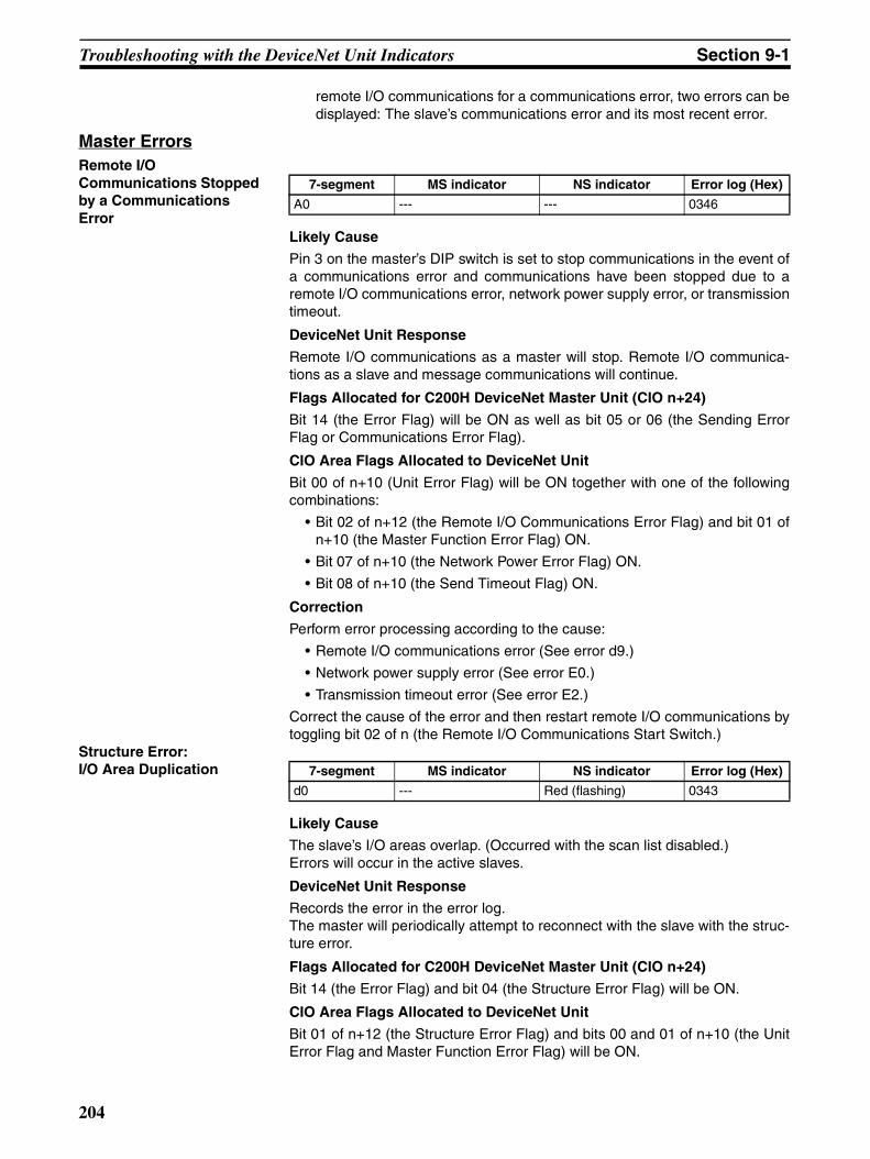
Troubleshooting with the DeviceNet Unit Indicators Section 9-1
remote I/O communications for a communications error, two errors can bedisplayed: The slave’s communications error and its most recent error.
Master ErrorsRemote I/O Communications Stopped by a Communications Error
Likely Cause
Pin 3 on the master’s DIP switch is set to stop communications in the event ofa communications error and communications have been stopped due to aremote I/O communications error, network power supply error, or transmissiontimeout.
DeviceNet Unit Response
Remote I/O communications as a master will stop. Remote I/O communica-tions as a slave and message communications will continue.
Flags Allocated for C200H DeviceNet Master Unit (CIO n+24)
Bit 14 (the Error Flag) will be ON as well as bit 05 or 06 (the Sending ErrorFlag or Communications Error Flag).
CIO Area Flags Allocated to DeviceNet Unit
Bit 00 of n+10 (Unit Error Flag) will be ON together with one of the followingcombinations:
• Bit 02 of n+12 (the Remote I/O Communications Error Flag) and bit 01 ofn+10 (the Master Function Error Flag) ON.
• Bit 07 of n+10 (the Network Power Error Flag) ON.
• Bit 08 of n+10 (the Send Timeout Flag) ON.
Correction
Perform error processing according to the cause:
• Remote I/O communications error (See error d9.)
• Network power supply error (See error E0.)
• Transmission timeout error (See error E2.)
Correct the cause of the error and then restart remote I/O communications bytoggling bit 02 of n (the Remote I/O Communications Start Switch.)
Structure Error: I/O Area Duplication
Likely Cause
The slave’s I/O areas overlap. (Occurred with the scan list disabled.)Errors will occur in the active slaves.
DeviceNet Unit Response
Records the error in the error log.The master will periodically attempt to reconnect with the slave with the struc-ture error.
Flags Allocated for C200H DeviceNet Master Unit (CIO n+24)
Bit 14 (the Error Flag) and bit 04 (the Structure Error Flag) will be ON.
CIO Area Flags Allocated to DeviceNet Unit
Bit 01 of n+12 (the Structure Error Flag) and bits 00 and 01 of n+10 (the UnitError Flag and Master Function Error Flag) will be ON.
7-segment MS indicator NS indicator Error log (Hex)
A0 --- --- 0346
7-segment MS indicator NS indicator Error log (Hex)
d0 --- Red (flashing) 0343
204

Troubleshooting with the DeviceNet Unit Indicators Section 9-1
Correction
Set the slaves’ node addresses again.Structure Error: I/O Area Range Exceeded
Likely Cause
The slave’s I/O area isn’t within the allowed range. (Occurs with the scan listdisabled.)
DeviceNet Unit Response
Records the error in the error log. The master will periodically attempt toreconnect with the slave with the structure error.
Flags Allocated for C200H DeviceNet Master Unit (CIO n+24)
Bit 14 (the Error Flag) and bit 04 (the Structure Error Flag) will be ON.
CIO Area Flags Allocated to DeviceNet Unit
Bit 01 of n+12 (the Structure Error Flag) and bits 00 and 01 of n+10 (the UnitError Flag and Master Function Error Flag) will be ON.
Correction
Set the slaves’ node addresses again or use user-set allocations.Structure Error:Unsupported Slave
Likely Cause
The size of the slave’s input and/or output area exceeded 200 bytes. (Occurswith the scan list disabled.)
DeviceNet Unit Response
Records the error in the error log.The master will periodically attempt to reconnect with the slave with the struc-ture error.
Flags Allocated for C200H DeviceNet Master Unit (CIO n+24)
Bit 14 (Error Flag) and bit 04 (the Structure Error Flag) will be ON.
CIO Area Flags Allocated to DeviceNet Unit
Bit 01 of n+12 (Structure Error Flag) and bits 00 and 01 of n+10 (Unit ErrorFlag and Master Function Error Flag) will be ON.
Correction
Use slaves with input and output areas of 200 bytes max.
Verification Error:Non-existent Slave
Likely Cause
A slave registered in the scan list doesn’t exist or the local node’s (master’s)node address is registered in the scan list. (Occurs with the scan list enabled.)
DeviceNet Unit Response
Records the error in the error log.
• If a slave is involved, the master will periodically attempt to reconnect.
• If the master is involved, it will not send an OPEN frame to itself.
7-segment MS indicator NS indicator Error log (Hex)
d1 --- Red (flashing) 0343
7-segment MS indicator NS indicator Error log (Hex)
d2 --- Red (flashing) 0343
7-segment MS indicator NS indicator Error log (Hex)
d5 --- Red (flashing) 0344
205
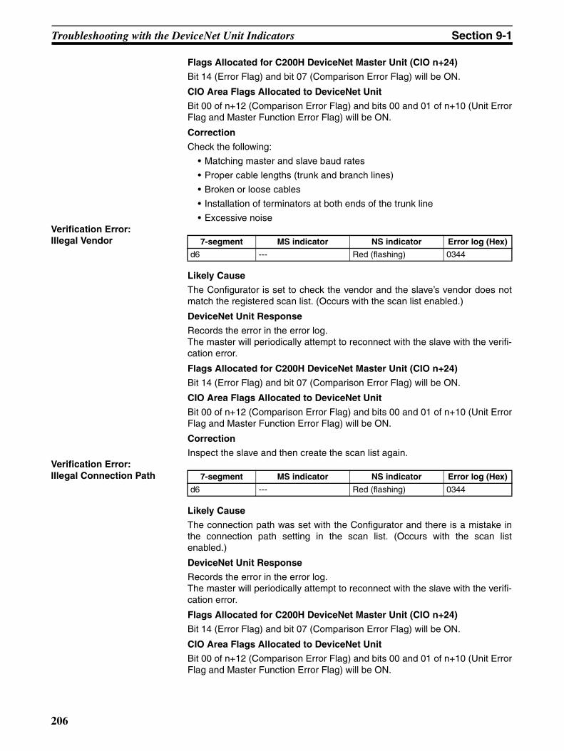
Troubleshooting with the DeviceNet Unit Indicators Section 9-1
Flags Allocated for C200H DeviceNet Master Unit (CIO n+24)
Bit 14 (Error Flag) and bit 07 (Comparison Error Flag) will be ON.
CIO Area Flags Allocated to DeviceNet Unit
Bit 00 of n+12 (Comparison Error Flag) and bits 00 and 01 of n+10 (Unit ErrorFlag and Master Function Error Flag) will be ON.
Correction
Check the following:
• Matching master and slave baud rates
• Proper cable lengths (trunk and branch lines)
• Broken or loose cables
• Installation of terminators at both ends of the trunk line
• Excessive noiseVerification Error:Illegal Vendor
Likely Cause
The Configurator is set to check the vendor and the slave’s vendor does notmatch the registered scan list. (Occurs with the scan list enabled.)
DeviceNet Unit Response
Records the error in the error log.The master will periodically attempt to reconnect with the slave with the verifi-cation error.
Flags Allocated for C200H DeviceNet Master Unit (CIO n+24)
Bit 14 (Error Flag) and bit 07 (Comparison Error Flag) will be ON.
CIO Area Flags Allocated to DeviceNet Unit
Bit 00 of n+12 (Comparison Error Flag) and bits 00 and 01 of n+10 (Unit ErrorFlag and Master Function Error Flag) will be ON.
Correction
Inspect the slave and then create the scan list again.Verification Error:Illegal Connection Path
Likely Cause
The connection path was set with the Configurator and there is a mistake inthe connection path setting in the scan list. (Occurs with the scan listenabled.)
DeviceNet Unit Response
Records the error in the error log.The master will periodically attempt to reconnect with the slave with the verifi-cation error.
Flags Allocated for C200H DeviceNet Master Unit (CIO n+24)
Bit 14 (Error Flag) and bit 07 (Comparison Error Flag) will be ON.
CIO Area Flags Allocated to DeviceNet Unit
Bit 00 of n+12 (Comparison Error Flag) and bits 00 and 01 of n+10 (Unit ErrorFlag and Master Function Error Flag) will be ON.
7-segment MS indicator NS indicator Error log (Hex)
d6 --- Red (flashing) 0344
7-segment MS indicator NS indicator Error log (Hex)
d6 --- Red (flashing) 0344
206
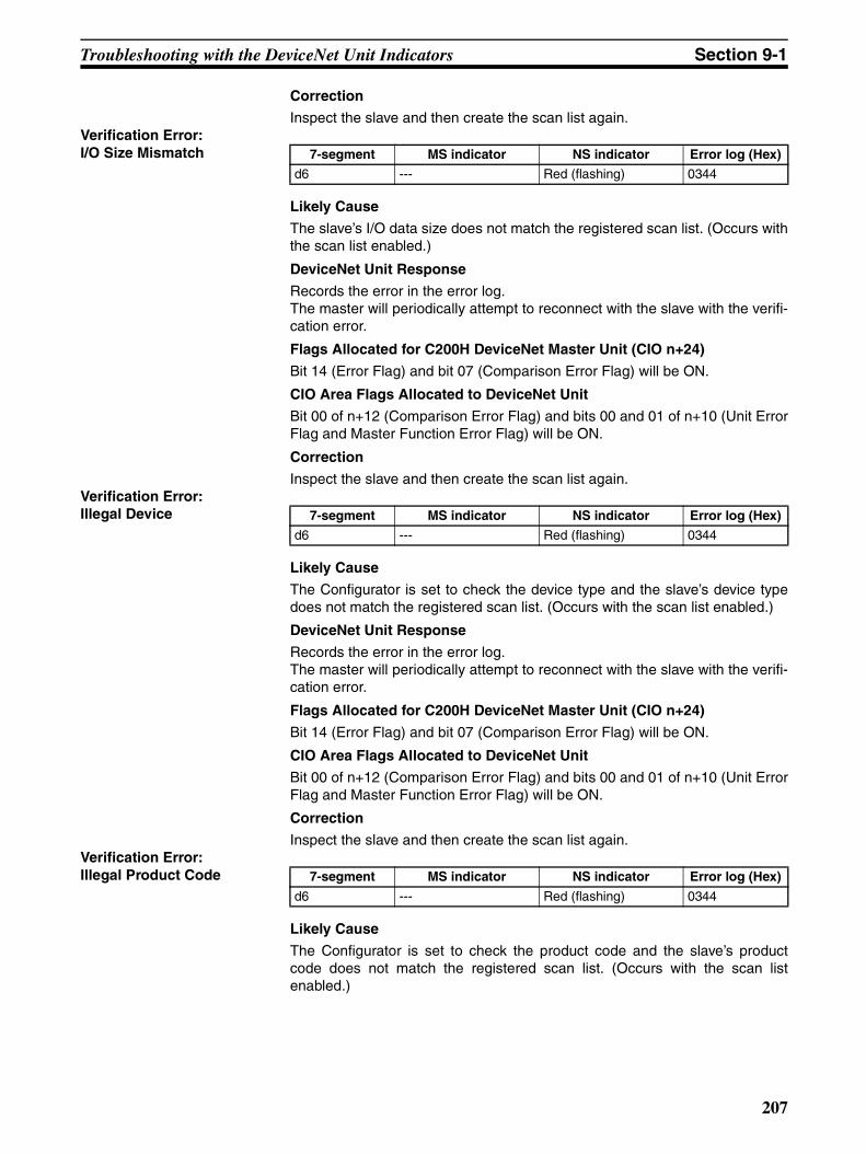
Troubleshooting with the DeviceNet Unit Indicators Section 9-1
Correction
Inspect the slave and then create the scan list again.Verification Error:I/O Size Mismatch
Likely Cause
The slave’s I/O data size does not match the registered scan list. (Occurs withthe scan list enabled.)
DeviceNet Unit Response
Records the error in the error log.The master will periodically attempt to reconnect with the slave with the verifi-cation error.
Flags Allocated for C200H DeviceNet Master Unit (CIO n+24)
Bit 14 (Error Flag) and bit 07 (Comparison Error Flag) will be ON.
CIO Area Flags Allocated to DeviceNet Unit
Bit 00 of n+12 (Comparison Error Flag) and bits 00 and 01 of n+10 (Unit ErrorFlag and Master Function Error Flag) will be ON.
Correction
Inspect the slave and then create the scan list again.Verification Error:Illegal Device
Likely Cause
The Configurator is set to check the device type and the slave’s device typedoes not match the registered scan list. (Occurs with the scan list enabled.)
DeviceNet Unit Response
Records the error in the error log.The master will periodically attempt to reconnect with the slave with the verifi-cation error.
Flags Allocated for C200H DeviceNet Master Unit (CIO n+24)
Bit 14 (Error Flag) and bit 07 (Comparison Error Flag) will be ON.
CIO Area Flags Allocated to DeviceNet Unit
Bit 00 of n+12 (Comparison Error Flag) and bits 00 and 01 of n+10 (Unit ErrorFlag and Master Function Error Flag) will be ON.
Correction
Inspect the slave and then create the scan list again.Verification Error:Illegal Product Code
Likely Cause
The Configurator is set to check the product code and the slave’s productcode does not match the registered scan list. (Occurs with the scan listenabled.)
7-segment MS indicator NS indicator Error log (Hex)
d6 --- Red (flashing) 0344
7-segment MS indicator NS indicator Error log (Hex)
d6 --- Red (flashing) 0344
7-segment MS indicator NS indicator Error log (Hex)
d6 --- Red (flashing) 0344
207
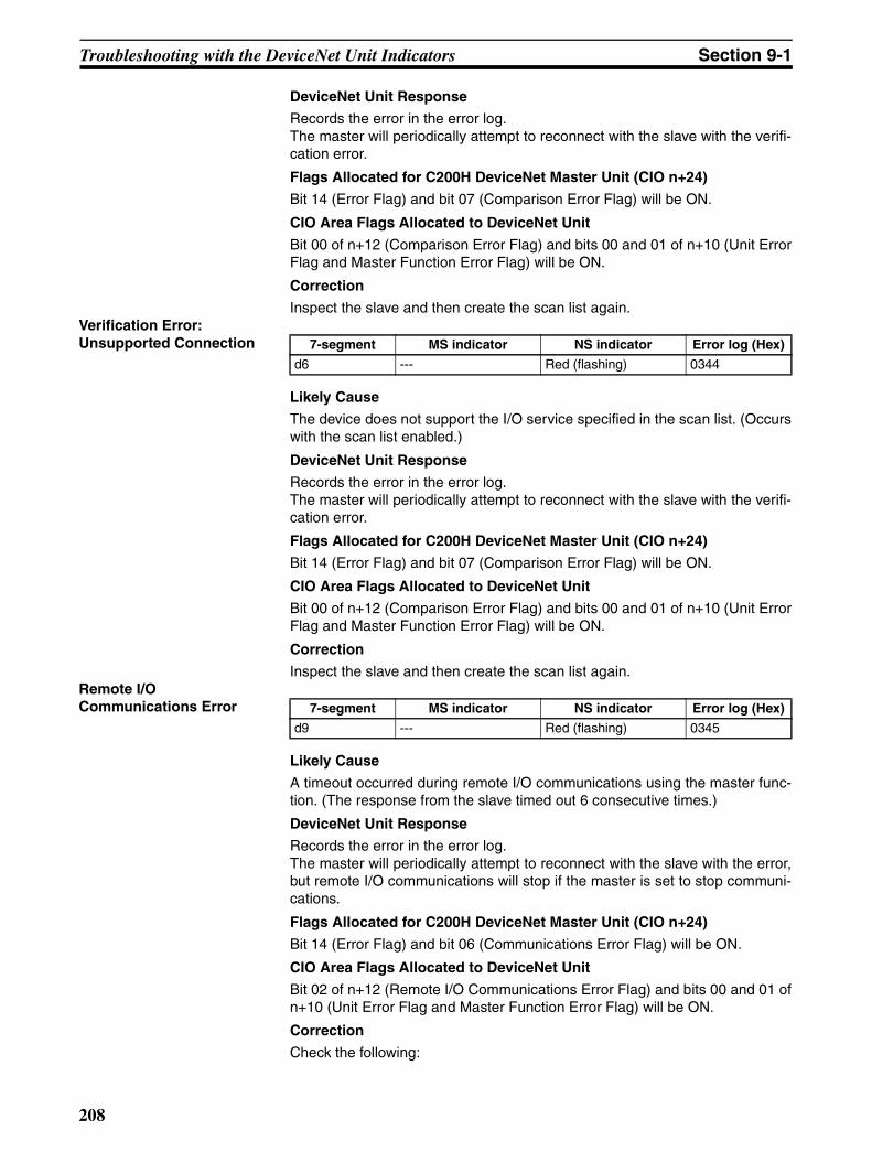
Troubleshooting with the DeviceNet Unit Indicators Section 9-1
DeviceNet Unit Response
Records the error in the error log.The master will periodically attempt to reconnect with the slave with the verifi-cation error.
Flags Allocated for C200H DeviceNet Master Unit (CIO n+24)
Bit 14 (Error Flag) and bit 07 (Comparison Error Flag) will be ON.
CIO Area Flags Allocated to DeviceNet Unit
Bit 00 of n+12 (Comparison Error Flag) and bits 00 and 01 of n+10 (Unit ErrorFlag and Master Function Error Flag) will be ON.
Correction
Inspect the slave and then create the scan list again.Verification Error:Unsupported Connection
Likely Cause
The device does not support the I/O service specified in the scan list. (Occurswith the scan list enabled.)
DeviceNet Unit Response
Records the error in the error log.The master will periodically attempt to reconnect with the slave with the verifi-cation error.
Flags Allocated for C200H DeviceNet Master Unit (CIO n+24)
Bit 14 (Error Flag) and bit 07 (Comparison Error Flag) will be ON.
CIO Area Flags Allocated to DeviceNet Unit
Bit 00 of n+12 (Comparison Error Flag) and bits 00 and 01 of n+10 (Unit ErrorFlag and Master Function Error Flag) will be ON.
Correction
Inspect the slave and then create the scan list again.Remote I/OCommunications Error
Likely Cause
A timeout occurred during remote I/O communications using the master func-tion. (The response from the slave timed out 6 consecutive times.)
DeviceNet Unit Response
Records the error in the error log.The master will periodically attempt to reconnect with the slave with the error,but remote I/O communications will stop if the master is set to stop communi-cations.
Flags Allocated for C200H DeviceNet Master Unit (CIO n+24)
Bit 14 (Error Flag) and bit 06 (Communications Error Flag) will be ON.
CIO Area Flags Allocated to DeviceNet Unit
Bit 02 of n+12 (Remote I/O Communications Error Flag) and bits 00 and 01 ofn+10 (Unit Error Flag and Master Function Error Flag) will be ON.
Correction
Check the following:
7-segment MS indicator NS indicator Error log (Hex)
d6 --- Red (flashing) 0344
7-segment MS indicator NS indicator Error log (Hex)
d9 --- Red (flashing) 0345
208

Troubleshooting with the DeviceNet Unit Indicators Section 9-1
• Matching master and slave baud rates
• Proper cable lengths (trunk and branch lines)
• Broken or loose cables
• Installation of terminators at both ends of the trunk line
• Excessive noise
Software Switch Setting ErrorsCPU Unit Status Error
Likely Cause
The software settings operation couldn’t be performed because the CPU Unitwasn’t in PROGRAM mode.
DeviceNet Unit Response
The only response is the error code displayed on the 7-segment display. Theerror display will be cleared the next time that a settings operation is com-pleted normally.
Correction
Switch the CPU Unit to PROGRAM mode and try the operation again.Unit Status Error
Likely Cause
The setting operation failed because the Unit could not perform the requestedprocess in its current status. The most common causes of Unit status errorsduring settings operations are listed below:
• The master was stopped and a software switch operation relating to themaster function was performed. (This does not include the master enableoperation.)
• The scan list was enabled and a software switch operation was performedthat can only be performed while the scan list is disabled. (Scan listenable and fixed allocation setting operations)
• The scan list was disabled and a software switch operation was per-formed that can only be performed while the scan list is enabled. (Clearscan list and Backup Unit settings file operations)
• The slave was stopped and a software switch operation relating to theslave function was performed. (This does not include the slave enableoperation.)
DeviceNet Unit Response
The only response is the error code displayed on the 7-segment display. Theerror display will be cleared the next time that a settings operation is com-pleted normally.
Correction
Change the Unit’s status to allow the operation and try the operation again.Structure Error
7-segment MS indicator NS indicator Error log (Hex)
C0 --- --- ---
7-segment MS indicator NS indicator Error log (Hex)
C2 --- --- ---
7-segment MS indicator NS indicator Error log (Hex)
C4 --- --- ---
209
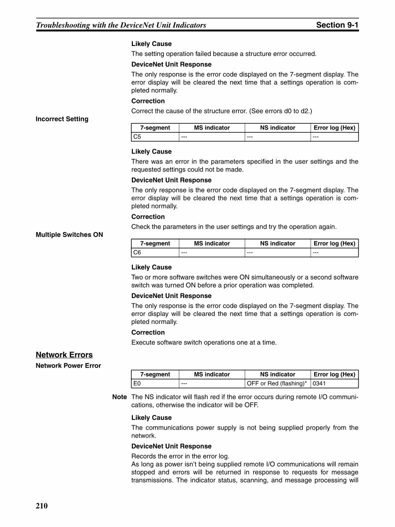
Troubleshooting with the DeviceNet Unit Indicators Section 9-1
Likely Cause
The setting operation failed because a structure error occurred.
DeviceNet Unit Response
The only response is the error code displayed on the 7-segment display. Theerror display will be cleared the next time that a settings operation is com-pleted normally.
Correction
Correct the cause of the structure error. (See errors d0 to d2.)Incorrect Setting
Likely Cause
There was an error in the parameters specified in the user settings and therequested settings could not be made.
DeviceNet Unit Response
The only response is the error code displayed on the 7-segment display. Theerror display will be cleared the next time that a settings operation is com-pleted normally.
Correction
Check the parameters in the user settings and try the operation again.Multiple Switches ON
Likely Cause
Two or more software switches were ON simultaneously or a second softwareswitch was turned ON before a prior operation was completed.
DeviceNet Unit Response
The only response is the error code displayed on the 7-segment display. Theerror display will be cleared the next time that a settings operation is com-pleted normally.
Correction
Execute software switch operations one at a time.
Network ErrorsNetwork Power Error
Note The NS indicator will flash red if the error occurs during remote I/O communi-cations, otherwise the indicator will be OFF.
Likely Cause
The communications power supply is not being supplied properly from thenetwork.
DeviceNet Unit Response
Records the error in the error log.As long as power isn’t being supplied remote I/O communications will remainstopped and errors will be returned in response to requests for messagetransmissions. The indicator status, scanning, and message processing will
7-segment MS indicator NS indicator Error log (Hex)
C5 --- --- ---
7-segment MS indicator NS indicator Error log (Hex)
C6 --- --- ---
7-segment MS indicator NS indicator Error log (Hex)
E0 --- OFF or Red (flashing)* 0341
210
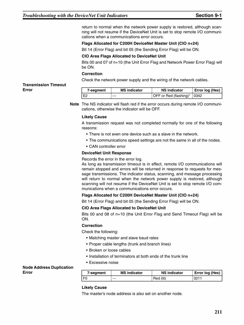
Troubleshooting with the DeviceNet Unit Indicators Section 9-1
return to normal when the network power supply is restored, although scan-ning will not resume if the DeviceNet Unit is set to stop remote I/O communi-cations when a communications error occurs.
Flags Allocated for C200H DeviceNet Master Unit (CIO n+24)
Bit 14 (Error Flag) and bit 05 (the Sending Error Flag) will be ON.
CIO Area Flags Allocated to DeviceNet Unit
Bits 00 and 07 of n+10 (the Unit Error Flag and Network Power Error Flag) willbe ON.
Correction
Check the network power supply and the wiring of the network cables.Transmission Timeout Error
Note The NS indicator will flash red if the error occurs during remote I/O communi-cations, otherwise the indicator will be OFF.
Likely Cause
A transmission request was not completed normally for one of the followingreasons:
• There is not even one device such as a slave in the network.
• The communications speed settings are not the same in all of the nodes.
• CAN controller error
DeviceNet Unit Response
Records the error in the error log.As long as transmission timeout is in effect, remote I/O communications willremain stopped and errors will be returned in response to requests for mes-sage transmissions. The indicator status, scanning, and message processingwill return to normal when the network power supply is restored, althoughscanning will not resume if the DeviceNet Unit is set to stop remote I/O com-munications when a communications error occurs.
Flags Allocated for C200H DeviceNet Master Unit (CIO n+24)
Bit 14 (Error Flag) and bit 05 (the Sending Error Flag) will be ON.
CIO Area Flags Allocated to DeviceNet Unit
Bits 00 and 08 of n+10 (the Unit Error Flag and Send Timeout Flag) will beON.
Correction
Check the following:
• Matching master and slave baud rates
• Proper cable lengths (trunk and branch lines)
• Broken or loose cables
• Installation of terminators at both ends of the trunk line
• Excessive noiseNode Address Duplication Error
Likely Cause
The master’s node address is also set on another node.
7-segment MS indicator NS indicator Error log (Hex)
E2 --- OFF or Red (flashing)* 0342
7-segment MS indicator NS indicator Error log (Hex)
F0 --- Red (lit) 0211
211

Troubleshooting with the DeviceNet Unit Indicators Section 9-1
DeviceNet Unit Response
Records the error in the error log.
• The Unit will go off–line and communications will be disabled. Errorresponses will be returned to all communications requests.
• The exchange of data with the CPU Unit will continue.
Flags Allocated for C200H DeviceNet Master Unit (CIO n+24)
Bit 14 (Error Flag) and bit 01 (the Node Address Duplicated/Bus Off Flag) willbe ON.
CIO Area Flags Allocated to DeviceNet Unit
Bits 00 and 06 of n+10 (the Unit Error Flag and Duplicated Node AddressFlag) will be ON.
Correction
Check the node addresses set on other nodes in the network. Correct the set-tings to eliminate the duplication and restart the DeviceNet Units.
Bus Off Detected
Likely Cause
A Bus Off condition was detected.
DeviceNet Unit Response
Records the error in the error log.
• The Unit will go off–line and communications will be disabled. Errorresponses will be returned to all communications requests.
• The exchange of data with the CPU Unit will continue.
Flags Allocated for C200H DeviceNet Master Unit (CIO n+24)
Bit 14 (Error Flag) and bit 01 (the Node Address Duplicated/Bus Off Flag) willbe ON.
CIO Area Flags Allocated to DeviceNet Unit
Bits 00 and 05 of n+10 (the Unit Error Flag and Bus Off Flag) will be ON.
Correction
Check the following:
• Matching master and slave baud rates
• Proper cable lengths (trunk and branch lines)
• Broken or loose cables
• Installation of terminators at both ends of the trunk line
• Excessive noise
Memory Access ErrorsMessage Monitoring Timer List Logic Error
Likely Cause
There is an error in the contents of the message monitoring timer list stored innon-volatile memory.
7-segment MS indicator NS indicator Error log (Hex)
F1 --- Red (lit) 0340
7-segment MS indicator NS indicator Error log (Hex)
E6 Red (flashing) --- 021A
212
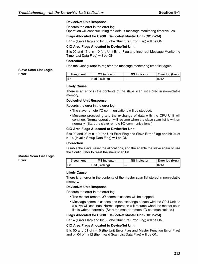
Troubleshooting with the DeviceNet Unit Indicators Section 9-1
DeviceNet Unit Response
Records the error in the error log.Operation will continue using the default message monitoring timer values.
Flags Allocated for C200H DeviceNet Master Unit (CIO n+24)
Bit 14 (Error Flag) and bit 03 (the Structure Error Flag) will be ON.
CIO Area Flags Allocated to DeviceNet Unit
Bits 00 and 13 of n+10 (the Unit Error Flag and Incorrect Message MonitoringTimer List Data Flag) will be ON.
Correction
Use the Configurator to register the message monitoring timer list again.Slave Scan List Logic Error
Likely Cause
There is an error in the contents of the slave scan list stored in non-volatilememory.
DeviceNet Unit Response
Records the error in the error log.
• The slave remote I/O communications will be stopped.
• Message processing and the exchange of data with the CPU Unit willcontinue. Normal operation will resume when the slave scan list is writtennormally. (Start the slave remote I/O communications.)
CIO Area Flags Allocated to DeviceNet Unit
Bits 00 and 03 of n+10 (the Unit Error Flag and Slave Error Flag) and bit 04 ofn+14 (Invalid Setup Data Flag) will be ON.
Correction
Disable the slave, reset the allocations, and the enable the slave again or usethe Configurator to reset the slave scan list.
Master Scan List Logic Error
Likely Cause
There is an error in the contents of the master scan list stored in non-volatilememory.
DeviceNet Unit Response
Records the error in the error log.
• The master remote I/O communications will be stopped.
• Message communications and the exchange of data with the CPU Unit asa slave will continue. Normal operation will resume when the master scanlist is written normally. (Start the master remote I/O communications.)
Flags Allocated for C200H DeviceNet Master Unit (CIO n+24)
Bit 14 (Error Flag) and bit 03 (the Structure Error Flag) will be ON.
CIO Area Flags Allocated to DeviceNet Unit
Bits 00 and 01 of n+10 (the Unit Error Flag and Master Function Error Flag)and bit 04 of n+12 (the Invalid Scan List Data Flag) will be ON.
7-segment MS indicator NS indicator Error log (Hex)
E7 Red (flashing) --- 021A
7-segment MS indicator NS indicator Error log (Hex)
E8 Red (flashing) --- 021A
213
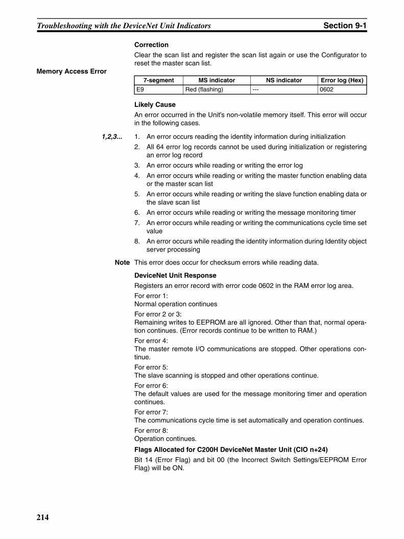
Troubleshooting with the DeviceNet Unit Indicators Section 9-1
Correction
Clear the scan list and register the scan list again or use the Configurator toreset the master scan list.
Memory Access Error
Likely Cause
An error occurred in the Unit’s non-volatile memory itself. This error will occurin the following cases.
1,2,3... 1. An error occurs reading the identity information during initialization
2. All 64 error log records cannot be used during initialization or registeringan error log record
3. An error occurs while reading or writing the error log
4. An error occurs while reading or writing the master function enabling dataor the master scan list
5. An error occurs while reading or writing the slave function enabling data orthe slave scan list
6. An error occurs while reading or writing the message monitoring timer
7. An error occurs while reading or writing the communications cycle time setvalue
8. An error occurs while reading the identity information during Identity objectserver processing
Note This error does occur for checksum errors while reading data.
DeviceNet Unit Response
Registers an error record with error code 0602 in the RAM error log area.
For error 1:Normal operation continues
For error 2 or 3: Remaining writes to EEPROM are all ignored. Other than that, normal opera-tion continues. (Error records continue to be written to RAM.)
For error 4:The master remote I/O communications are stopped. Other operations con-tinue.
For error 5:The slave scanning is stopped and other operations continue.
For error 6:The default values are used for the message monitoring timer and operationcontinues.
For error 7:The communications cycle time is set automatically and operation continues.
For error 8:Operation continues.
Flags Allocated for C200H DeviceNet Master Unit (CIO n+24)
Bit 14 (Error Flag) and bit 00 (the Incorrect Switch Settings/EEPROM ErrorFlag) will be ON.
7-segment MS indicator NS indicator Error log (Hex)
E9 Red (flashing) --- 0602
214
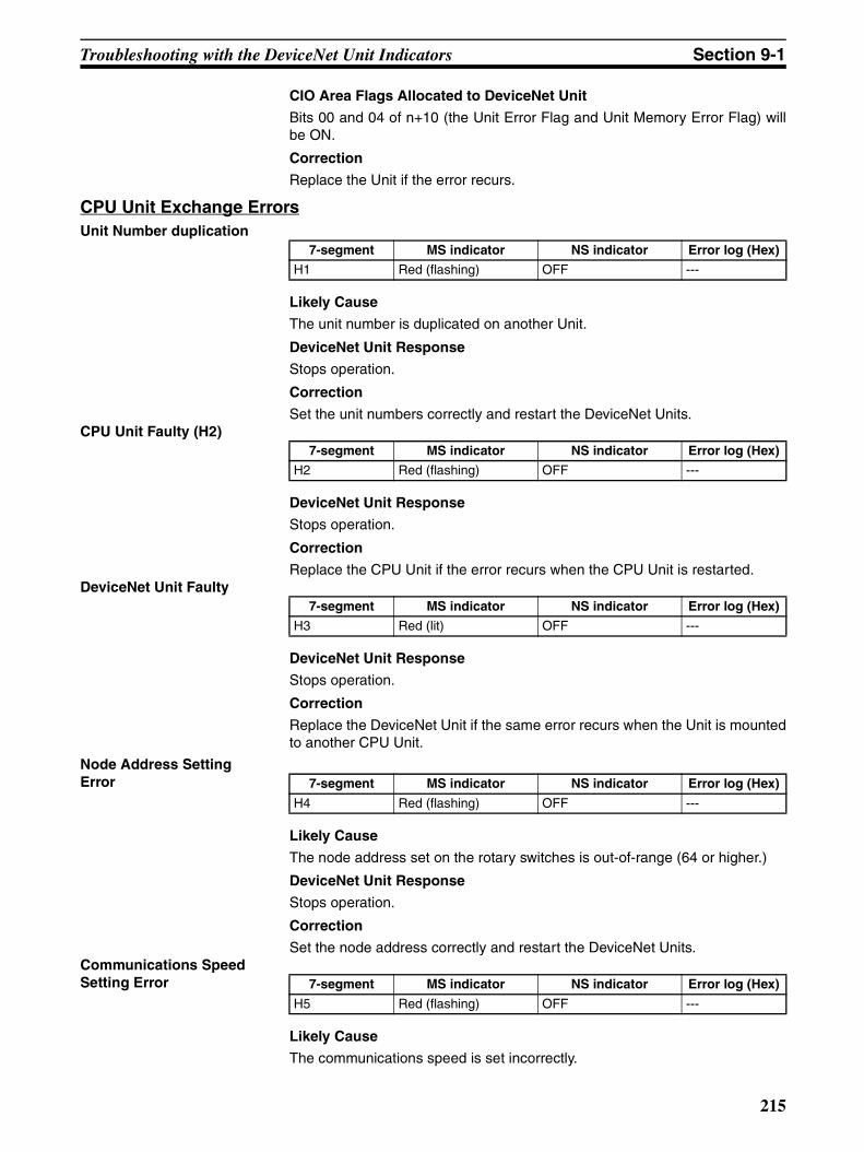
Troubleshooting with the DeviceNet Unit Indicators Section 9-1
CIO Area Flags Allocated to DeviceNet Unit
Bits 00 and 04 of n+10 (the Unit Error Flag and Unit Memory Error Flag) willbe ON.
Correction
Replace the Unit if the error recurs.
CPU Unit Exchange ErrorsUnit Number duplication
Likely Cause
The unit number is duplicated on another Unit.
DeviceNet Unit Response
Stops operation.
Correction
Set the unit numbers correctly and restart the DeviceNet Units.CPU Unit Faulty (H2)
DeviceNet Unit Response
Stops operation.
Correction
Replace the CPU Unit if the error recurs when the CPU Unit is restarted.DeviceNet Unit Faulty
DeviceNet Unit Response
Stops operation.
Correction
Replace the DeviceNet Unit if the same error recurs when the Unit is mountedto another CPU Unit.
Node Address Setting Error
Likely Cause
The node address set on the rotary switches is out-of-range (64 or higher.)
DeviceNet Unit Response
Stops operation.
Correction
Set the node address correctly and restart the DeviceNet Units.Communications Speed Setting Error
Likely Cause
The communications speed is set incorrectly.
7-segment MS indicator NS indicator Error log (Hex)
H1 Red (flashing) OFF ---
7-segment MS indicator NS indicator Error log (Hex)
H2 Red (flashing) OFF ---
7-segment MS indicator NS indicator Error log (Hex)
H3 Red (lit) OFF ---
7-segment MS indicator NS indicator Error log (Hex)
H4 Red (flashing) OFF ---
7-segment MS indicator NS indicator Error log (Hex)
H5 Red (flashing) OFF ---
215
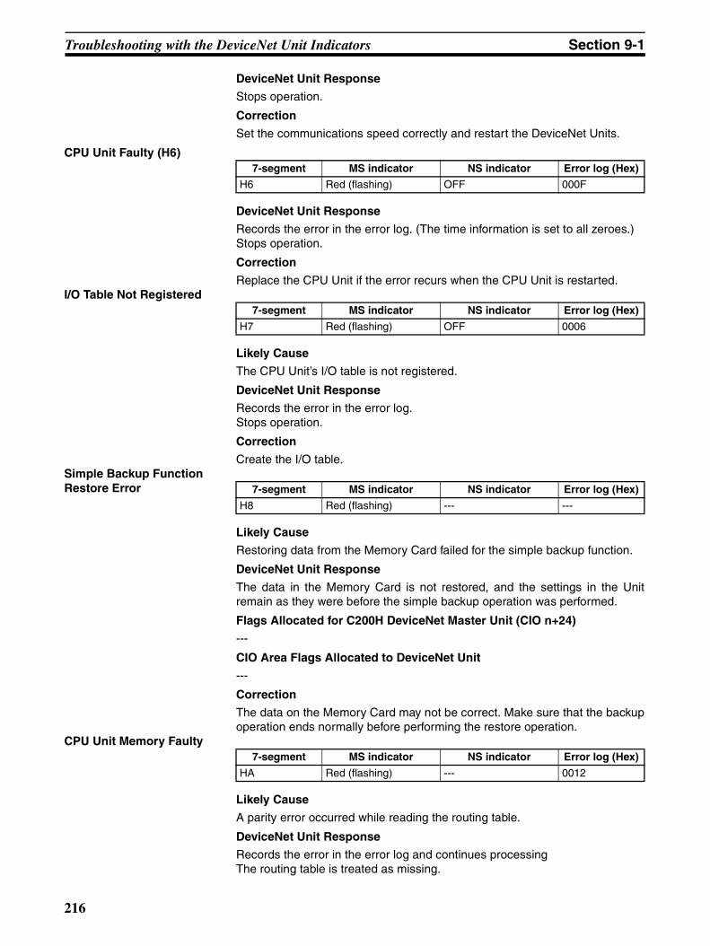
Troubleshooting with the DeviceNet Unit Indicators Section 9-1
DeviceNet Unit Response
Stops operation.
Correction
Set the communications speed correctly and restart the DeviceNet Units.
CPU Unit Faulty (H6)
DeviceNet Unit Response
Records the error in the error log. (The time information is set to all zeroes.)Stops operation.
Correction
Replace the CPU Unit if the error recurs when the CPU Unit is restarted.I/O Table Not Registered
Likely Cause
The CPU Unit’s I/O table is not registered.
DeviceNet Unit Response
Records the error in the error log.Stops operation.
Correction
Create the I/O table.Simple Backup Function Restore Error
Likely Cause
Restoring data from the Memory Card failed for the simple backup function.
DeviceNet Unit Response
The data in the Memory Card is not restored, and the settings in the Unitremain as they were before the simple backup operation was performed.
Flags Allocated for C200H DeviceNet Master Unit (CIO n+24)
---
CIO Area Flags Allocated to DeviceNet Unit
---
Correction
The data on the Memory Card may not be correct. Make sure that the backupoperation ends normally before performing the restore operation.
CPU Unit Memory Faulty
Likely Cause
A parity error occurred while reading the routing table.
DeviceNet Unit Response
Records the error in the error log and continues processingThe routing table is treated as missing.
7-segment MS indicator NS indicator Error log (Hex)
H6 Red (flashing) OFF 000F
7-segment MS indicator NS indicator Error log (Hex)
H7 Red (flashing) OFF 0006
7-segment MS indicator NS indicator Error log (Hex)
H8 Red (flashing) --- ---
7-segment MS indicator NS indicator Error log (Hex)
HA Red (flashing) --- 0012
216
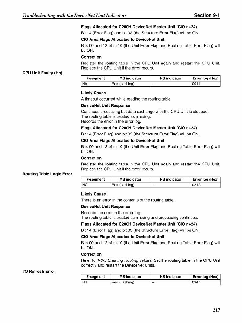
Troubleshooting with the DeviceNet Unit Indicators Section 9-1
Flags Allocated for C200H DeviceNet Master Unit (CIO n+24)
Bit 14 (Error Flag) and bit 03 (the Structure Error Flag) will be ON.
CIO Area Flags Allocated to DeviceNet Unit
Bits 00 and 12 of n+10 (the Unit Error Flag and Routing Table Error Flag) willbe ON.
Correction
Register the routing table in the CPU Unit again and restart the CPU Unit.Replace the CPU Unit if the error recurs.
CPU Unit Faulty (Hb)
Likely Cause
A timeout occurred while reading the routing table.
DeviceNet Unit Response
Continues processing but data exchange with the CPU Unit is stopped.The routing table is treated as missing.Records the error in the error log.
Flags Allocated for C200H DeviceNet Master Unit (CIO n+24)
Bit 14 (Error Flag) and bit 03 (the Structure Error Flag) will be ON.
CIO Area Flags Allocated to DeviceNet Unit
Bits 00 and 12 of n+10 (the Unit Error Flag and Routing Table Error Flag) willbe ON.
Correction
Register the routing table in the CPU Unit again and restart the CPU Unit.Replace the CPU Unit if the error recurs.
Routing Table Logic Error
Likely Cause
There is an error in the contents of the routing table.
DeviceNet Unit Response
Records the error in the error log.The routing table is treated as missing and processing continues.
Flags Allocated for C200H DeviceNet Master Unit (CIO n+24)
Bit 14 (Error Flag) and bit 03 (the Structure Error Flag) will be ON.
CIO Area Flags Allocated to DeviceNet Unit
Bits 00 and 12 of n+10 (the Unit Error Flag and Routing Table Error Flag) willbe ON.
Correction
Refer to 1-6-3 Creating Routing Tables. Set the routing table in the CPU Unitcorrectly and restart the DeviceNet Units.
I/O Refresh Error
7-segment MS indicator NS indicator Error log (Hex)
Hb Red (flashing) --- 0011
7-segment MS indicator NS indicator Error log (Hex)
HC Red (flashing) --- 021A
7-segment MS indicator NS indicator Error log (Hex)
Hd Red (flashing) --- 0347
217

Troubleshooting with the DeviceNet Unit Indicators Section 9-1
Likely Cause
The I/O areas set in the master scan list or slave scan list do not exist in theCPU Unit. This error can occur when the Unit is mounted to a different CPUUnit with a different number of EM banks or EM that has been converted tofile memory.
Note This error may occur during remote I/O communications, too.
DeviceNet Unit Response
Records the error in the error log.Stops remote I/O communications for the function (master or slave) using thenon-existent area.There is a possibility that this error will occur again. If it does occur again,restart remote I/O communications to return the system to normal operation.
Flags Allocated for C200H DeviceNet Master Unit (CIO n+24)
Bit 14 (Error Flag) and bit 03 (the Structure Error Flag) will be ON.
CIO Area Flags Allocated to DeviceNet Unit
Bit 00 of n+10 (Unit Error Flag) will be ON together with one of the followingcombinations:
• Bit 05 of n+12 (the Master I/O Refresh Error Flag) and bit 01 of n+10 (theMaster Function Error Flag) ON.
• Bit 05 of n+14 (Remote I/O Refresh Error Flag) and bit 03 of n+10 (theSlave Error Flag) ON.
Correction
Check the master scan list and slave scan list and reset with a correct alloca-tion.
CPU Unit Service Monitoring Error
Likely Cause
Servicing from the CPU Unit is not at fixed intervals. Servicing is normallymonitored at 11 s.
DeviceNet Unit Response
• Records the error in the error log.
• Stops master and slave remote I/O communications.Performs the following processing if it receives FINS frames that must bepassed along to the CPU Unit:
• Returns an error response (0302 Hex) to commands requiring a re-sponse.
• Discards other frames and stores an error record (010B Hex) in the er-ror log.
Note There is a possibility that this error will occur again. If it does occuragain, restart remote I/O communications to return the system tonormal operation.
Flags Allocated for C200H DeviceNet Master Unit (CIO n+24)
There is no status notification because communications with the CPU Unit aredisabled.
CIO Area Flags Allocated to DeviceNet Unit
There is no status notification because communications with the CPU Unit aredisabled.
7-segment MS indicator NS indicator Error log (Hex)
HE Red (flashing) --- 0002
218

Troubleshooting with the DeviceNet Unit Indicators Section 9-1
Correction
Inspect the CPU Unit’s operating environment.CPU Unit Watchdog Timer Error
Likely Cause
An error occurred in the CPU Unit.
Note The CPU Unit’s watchdog timer error can occur during initialization.
DeviceNet Unit Response
• Records the error in the error log.
• Stops master and slave remote I/O communications.Performs the following processing if it receives FINS frames that must bepassed along to the CPU Unit:
• Returns an error response (0302 Hex) to commands requiring a re-sponse.
• Discards other frames and stores an error record (010B Hex) in the er-ror log.
Flags Allocated for C200H DeviceNet Master Unit (CIO n+24)
There is no status notification because communications with the CPU Unit aredisabled.
CIO Area Flags Allocated to DeviceNet Unit
There is no status notification because communications with the CPU Unit aredisabled.
Correction
Replace the CPU Unit.CPU Unit Fatal Error
DeviceNet Unit Response
Output data is set to 0. (With the master, these are output bits. With the slave,these are input bits to the other master.)
Output OFF Error
Likely Cause
The Output OFF Bit (A50015) was turned ON in the CPU Unit.
DeviceNet Unit Response
Output data is set to 0. (With the master, these are output bits. With the slave,these are input bits to the other master.)
Slave ErrorsRemote I/O Communications Error
7-segment MS indicator NS indicator Error log (Hex)
HF Red (flashing) --- 0001
7-segment MS indicator NS indicator Error log (Hex)
--- --- --- ---
7-segment MS indicator NS indicator Error log (Hex)
--- --- --- ---
7-segment MS indicator NS indicator Error log (Hex)
L9 --- Red (flashing) 0345
219
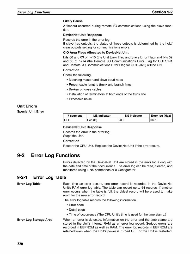
Error Log Functions Section 9-2
Likely Cause
A timeout occurred during remote I/O communications using the slave func-tion.
DeviceNet Unit Response
Records the error in the error log.If slave has outputs, the status of those outputs is determined by the hold/clear outputs setting for communications errors.
CIO Area Flags Allocated to DeviceNet Unit
Bits 00 and 03 of n+10 (the Unit Error Flag and Slave Error Flag) and bits 02and 03 of n+14 (the Remote I/O Communications Error Flag for OUT1/IN1and Remote I/O Communications Error Flag for OUT2/IN2) will be ON.
Correction
Check the following:
• Matching master and slave baud rates
• Proper cable lengths (trunk and branch lines)
• Broken or loose cables
• Installation of terminators at both ends of the trunk line
• Excessive noise
Unit ErrorsSpecial Unit Error
DeviceNet Unit Response
Records the error in the error log.Stops the Unit.
Correction
Restart the CPU Unit. Replace the DeviceNet Unit if the error recurs.
9-2 Error Log FunctionsErrors detected by the DeviceNet Unit are stored in the error log along withthe date and time of their occurrence. The error log can be read, cleared, andmonitored using FINS commands or a Configurator.
9-2-1 Error Log TableError Log Table Each time an error occurs, one error record is recorded in the DeviceNet
Unit’s RAM error log table. The table can record up to 64 records. If anothererror occurs when the table is full, the oldest record will be erased to makeroom for the new error record.
The error log table records the following information.
• Error code
• Detail code
• Time of occurrence (The CPU Unit’s time is used for the time stamp.)
Error Log Storage Area When an error is detected, information on the error and the time stamp arestored in the Unit’s internal RAM as an error log record. Serious errors arerecorded in EEPROM as well as RAM. The error log records in EEPROM areretained even when the Unit’s power is turned OFF or the Unit is restarted.
7-segment MS indicator NS indicator Error log (Hex)
OFF Red (lit) OFF 0601
220

Error Log Functions Section 9-2
The error log records in EEPROM are copied to RAM when the DeviceNetUnit is turned ON.
When the error log is read with a FINS command or from the Configurator,only the error log records in RAM are read. When the error log is cleared witha FINS command or from the Configurator, the error log records in RAM andEEPROM are erased.
Note Refer to 9-2-2 Error Codes and Detail Codes for a table listing the error codes.
Reading and Clearing the Error Log
The error log table can be read or cleared by sending a FINS command to theDeviceNet Unit. Use the DeviceNet Unit’s unit address as the FINS com-mand’s destination unit address. (The unit address is the unit number+10Hex.)
Refer to the SYSMAC CS/CJ Series Communication Commands ReferenceManual (W342) for details on using the FINS commands. Refer to the Appen-dix E FINS Commands and Responses for DeviceNet Units for details onFINS commands addressed to the DeviceNet Unit.
When using the Configurator, the error log can be monitored with the mastererror history read operation. With the Configurator, the error log can only bemonitored and the data cannot be saved.
Time Information The CPU Unit’s time information is used for the time stamps in the DeviceNetUnit’s error log records. If the time information cannot be read from the CPUUnit, the time stamp will contain all zeroes.
The DeviceNet Unit’s time stamps will not be correct or consistent unless thetime has been correctly in the CPU Unit. Moreover, if the battery is replaced ina CS/CJ-series CPU Unit, the time must be set again the next time that poweris turned ON.
9-2-2 Error Codes and Detail CodesError code (Hex)
Error Detail code Record stored in EEPROM
First byte Second byte
0001 CPU Unit watchdog timer error 00 Hex 00 Hex Yes
0002 CPU Unit service monitoring error (The servic-ing time from the CPU Unit is not fixed.)
Monitoring time (ms) Yes
0006 Other CPU error Bit 14 ON: Duplicate unit number settingBit 11 ON: Unit not in registered I/O tableOther bits: Reserved for system
Yes
000F CPU Unit initialization error 00 Hex 00 Hex Yes
0011 Event timeout MRC SRC Yes
0012 CPU Unit memory error 01 Hex: Read error02 Hex: Write error
03 Hex: Routing table04 Hex: CPU Bus Unit set-tings error05 Hex: Special Unit CIO or DM allocation
Yes
221
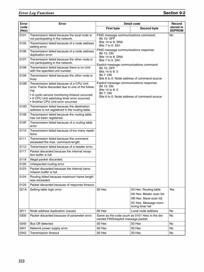
Error Log Functions Section 9-2
0101 Transmission failed because the local node is not participating in the network.
FINS message communications command:Bit 15: OFFBits 14 to 8: SNABits 7 to 0: SA1
FINS message communications response:Bit 15: ONBits 14 to 8: DNABits 7 to 0: DA1
Explicit message communications command:Bit 15: OFFBits 14 to 8: 0Bit 7: ONBits 6 to 0: Node address of command source
Explicit message communications response:Bit 15: ONBits 14 to 8: 0Bit 7: ONBits 6 to 0: Node address of command source
No
0105 Transmission failed because of a node address setting error.
0106 Transmission failed because of a node address duplication error.
0107 Transmission failed because the other node is not participating in the network.
0108 Transmission failed because there is no Unit with the specified unit number.
0109 Transmission failed because the other node is busy.
010B Transmission failed because of a CPU Unit error. Frame discarded due to one of the follow-ing:
• A cyclic service monitoring timeout occurred.• A CPU Unit watchdog timer error occurred.• Another CPU Unit error occurred.
010D Transmission failed because the destination address is not registered in the routing table.
010E Transmission failed because the routing table has not been registered.
010F Transmission failed because of a routing table error.
0110 Transmission failed because of too many repeti-tions.
0111 Transmission failed because the command exceeded the max. command length.
0112 Transmission failed because of a header error.
0117 Packet discarded because the internal recep-tion buffer is full.
0118 Illegal packet discarded.
0120 Unexpected routing error
0123 Packet discarded because the internal trans-mission buffer is full.
0124 Routing failed because maximum frame length was exceeded.
0125 Packet discarded because of response timeout.
021A Setting table logic error 00 Hex 03 Hex: Routing table 0A Hex: Master scan list0B Hex: Slave scan list
0C Hex: Message moni-toring timer list
Yes
0211 Node address duplication (cause) 00 Hex Local node address No
0300 Packet discarded because of parameter error. Same as the code (such as 0101 Hex) in the dis-carded FINS/explicit message packet.
No
0340 Bus Off detected 00 Hex 00 Hex No
0341 Network power supply error 00 Hex 00 Hex No
0342 Transmission timeout 00 Hex 00 Hex No
Error code (Hex)
Error Detail code Record stored in EEPROM
First byte Second byte
222

Error Log Functions Section 9-2
Note The error information is not written to EEPROM when a memory error occursin the error log area (EEPROM).
0343 Structure error 01 Hex: I/O area dupli-cation02 Hex: I/O area range exceeded03 Hex: Unsupported slave
Slave’s node address No
0344 Verification error 01 Hex: Non-existent slave
02 Hex: Illegal header03 Hex: Illegal device type
04 Hex: Illegal product code05 Hex: Unsupported connection06 Hex: I/O size mis-match
07 Hex: Illegal connec-tion path
Slave’s node address No
0345 Remote I/O communications error 01 Hex: Master
02 Hex: Slave
Master:Slave’s node address
Slave:Master’s node address
No
0346 Remote I/O communications stopped because of a remote I/O communications error.
01 Hex: Remote I/O communications error
02 Hex: Network power supply error03 Hex: Transmission timeout
Remote I/O comm. error:Slave’s node address
Power supply error:Local (master’s) node address
Transmission timeout:Local (master’s) node address
No
0347 I/O refreshing error 01 Hex: Master02 Hex: Slave
00 Hex No
0348 Message discarded because a new request was received.
Same as the code (such as 0101 Hex) in the dis-carded FINS/explicit message packet.
No
0601 Special Unit error Uncertain contents Yes
0602 Special Unit memory error 01 Hex: Read error02 Hex: Write error
06 Hex: Error log09 Hex: Identity data
0A Hex: Master scan list0B Hex: Slave scan list0C Hex: Message moni-toring timer list0D Hex: Communications cycle time setting
Yes(See note.)
Error code (Hex)
Error Detail code Record stored in EEPROM
First byte Second byte
223
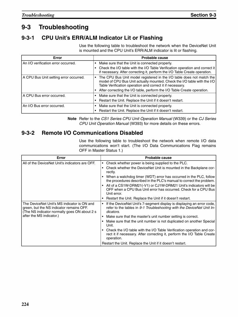
Troubleshooting Section 9-3
9-3 Troubleshooting
9-3-1 CPU Unit’s ERR/ALM Indicator Lit or FlashingUse the following table to troubleshoot the network when the DeviceNet Unitis mounted and the CPU Unit’s ERR/ALM indicator is lit or flashing.
Note Refer to the CS1 Series CPU Unit Operation Manual (W339) or the CJ SeriesCPU Unit Operation Manual (W393) for more details on these errors.
9-3-2 Remote I/O Communications DisabledUse the following table to troubleshoot the network when remote I/O datacommunications won’t start. (The I/O Data Communications Flag remainsOFF in Master Status 1.)
Error Probable cause
An I/O verification error occurred. • Make sure that the Unit is connected properly.• Check the I/O table with the I/O Table Verification operation and correct it
if necessary. After correcting it, perform the I/O Table Create operation.
A CPU Bus Unit setting error occurred. • The CPU Bus Unit model registered in the I/O table does not match themodel of CPU Bus Unit actually mounted. Check the I/O table with the I/OTable Verification operation and correct it if necessary.
• After correcting the I/O table, perform the I/O Table Create operation.
A CPU Bus error occurred. • Make sure that the Unit is connected properly.• Restart the Unit. Replace the Unit if it doesn’t restart.
An I/O Bus error occurred. • Make sure that the Unit is connected properly.• Restart the Unit. Replace the Unit if it doesn’t restart.
Error Probable cause
All of the DeviceNet Unit’s indicators are OFF. • Check whether power is being supplied to the PLC.• Check whether the DeviceNet Unit is mounted in the Backplane cor-
rectly.• When a watchdog timer (WDT) error has occurred in the PLC, follow
the procedures described in the PLC’s manual to correct the problem.• All of a CS1W-DRM21(-V1) or CJ1W-DRM21 Unit’s indicators will be
OFF when a CPU Bus Unit error has occurred. Check for a CPU BusUnit error.
• Restart the Unit. Replace the Unit if it doesn’t restart.
The DeviceNet Unit’s MS indicator is ON and green, but the NS indicator remains OFF.(The NS indicator normally goes ON about 2 s after the MS indicator.)
• If the DeviceNet Unit’s 7-segment display is displaying an error code,refer to the tables in 9-1 Troubleshooting with the DeviceNet Unit In-dicators.
• Make sure that the master’s unit number setting is correct.• Make sure that the unit number is not duplicated on another Special
Unit.• Check the I/O table with the I/O Table Verification operation and cor-
rect it if necessary. After correcting it, perform the I/O Table Createoperation.
Restart the Unit. Replace the Unit if it doesn’t restart.
224
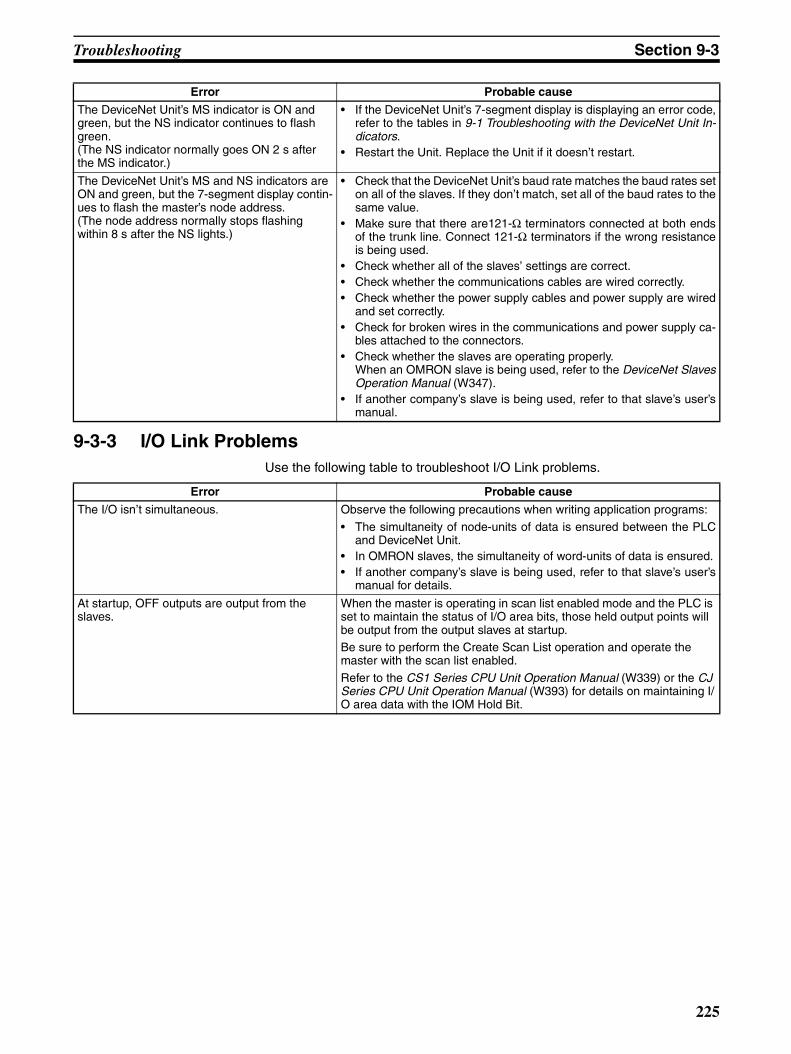
Troubleshooting Section 9-3
9-3-3 I/O Link ProblemsUse the following table to troubleshoot I/O Link problems.
The DeviceNet Unit’s MS indicator is ON and green, but the NS indicator continues to flash green.(The NS indicator normally goes ON 2 s after the MS indicator.)
• If the DeviceNet Unit’s 7-segment display is displaying an error code,refer to the tables in 9-1 Troubleshooting with the DeviceNet Unit In-dicators.
• Restart the Unit. Replace the Unit if it doesn’t restart.
The DeviceNet Unit’s MS and NS indicators are ON and green, but the 7-segment display contin-ues to flash the master’s node address.(The node address normally stops flashing within 8 s after the NS lights.)
• Check that the DeviceNet Unit’s baud rate matches the baud rates seton all of the slaves. If they don’t match, set all of the baud rates to thesame value.
• Make sure that there are121-Ω terminators connected at both endsof the trunk line. Connect 121-Ω terminators if the wrong resistanceis being used.
• Check whether all of the slaves’ settings are correct.• Check whether the communications cables are wired correctly.• Check whether the power supply cables and power supply are wired
and set correctly.• Check for broken wires in the communications and power supply ca-
bles attached to the connectors.• Check whether the slaves are operating properly.
When an OMRON slave is being used, refer to the DeviceNet SlavesOperation Manual (W347).
• If another company’s slave is being used, refer to that slave’s user’smanual.
Error Probable cause
Error Probable cause
The I/O isn’t simultaneous. Observe the following precautions when writing application programs:
• The simultaneity of node-units of data is ensured between the PLCand DeviceNet Unit.
• In OMRON slaves, the simultaneity of word-units of data is ensured.• If another company’s slave is being used, refer to that slave’s user’s
manual for details.
At startup, OFF outputs are output from the slaves.
When the master is operating in scan list enabled mode and the PLC is set to maintain the status of I/O area bits, those held output points will be output from the output slaves at startup.Be sure to perform the Create Scan List operation and operate the master with the scan list enabled.
Refer to the CS1 Series CPU Unit Operation Manual (W339) or the CJ Series CPU Unit Operation Manual (W393) for details on maintaining I/O area data with the IOM Hold Bit.
225
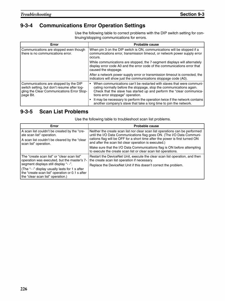
Troubleshooting Section 9-3
9-3-4 Communications Error Operation SettingsUse the following table to correct problems with the DIP switch setting for con-tinuing/stopping communications for errors.
9-3-5 Scan List ProblemsUse the following table to troubleshoot scan list problems.
Error Probable cause
Communications are stopped even though there is no communications error.
When pin 3 on the DIP switch is ON, communications will be stopped if a communications error, transmission timeout, or network power supply error occurs.While communications are stopped, the 7-segment displays will alternately display error code A0 and the error code of the communications error that caused the stoppage.After a network power supply error or transmission timeout is corrected, the indicators will show just the communications stoppage code (A0).
Communications are stopped by the DIP switch setting, but don’t resume after tog-gling the Clear Communications Error Stop-page Bit.
• When communications can’t be restarted with slaves that were communi-cating normally before the stoppage, stop the communications again.Check that the slave has started up and perform the “clear communica-tions error stoppage” operation.
• It may be necessary to perform the operation twice if the network containsanother company’s slave that take a long time to join the network.
Error Probable cause
A scan list couldn’t be created by the “cre-ate scan list” operation.A scan list couldn’t be cleared by the “clear scan list” operation.
Neither the create scan list nor clear scan list operations can be performed until the I/O Data Communications flag goes ON. (The I/O Data Communi-cations flag will be OFF for a short time after the power is first turned ON and after the scan list clear operation is executed.)Make sure that the I/O Data Communications flag is ON before attempting to execute the create scan list or clear scan list operations.
The “create scan list” or “clear scan list” operation was executed, but the master’s 7-segment displays still display “- -”.(The “- -” display usually lasts for 1 s after the “create scan list” operation or 0.1 s after the “clear scan list” operation.)
Restart the DeviceNet Unit, execute the clear scan list operation, and then the create scan list operation if necessary.
Replace the DeviceNet Unit if this doesn’t correct the problem.
226
Maintenance and Replacement Section 9-4
9-4 Maintenance and ReplacementThis section describes the routine cleaning and inspection recommended asregular maintenance as well as the Unit replacement procedure required if aDeviceNet Unit fails.
9-4-1 CleaningClean the DeviceNet Units regularly as described below in order to keep thenetwork in its optimal operating condition.
• Wipe the Unit daily with a dry, soft cloth.
• When a spot can’t be removed with a dry cloth, dampen the cloth with aneutral cleanser (2% solution), wring out the cloth, and wipe the Unit.
• A smudge may remain on the Unit from gum, vinyl, or tape that was left onfor a long time. Remove the smudge when cleaning.
!Caution Never use volatile solvents such as paint thinner, benzene, or chemical wipes.These substances could damage the surface of the Unit.
9-4-2 InspectionBe sure to inspect the system periodically to keep it in its optimal operatingcondition. In general, inspect the system once every 6 to 12 months, butinspect more frequently if the system is used with high temperature or humid-ity or under dirty/dusty conditions.
Inspection Equipment Prepare the following equipment before inspecting the system.
Required Equipment
Have a standard and Phillips-head screwdriver, multimeter, alcohol, and aclean cloth.
Equipment Required Occasionally
Depending on the system conditions, a synchroscope, oscilloscope, ther-mometer, or hygrometer (to measure humidity) might be needed.
Inspection Procedure Check the items in the following table and correct any items that are belowstandard.
Item Standard Equipment
Environmental conditions
Ambient and cabinet temperature 0°C to 55°C Thermometer
Ambient and cabinet humidity(with no condensation or icing)
10% to 90% Hygrometer
Dust/dirt accumulation None ---
Installation Are the Units installed securely? No looseness ---
Are the communications connec-tors fully inserted?
No looseness ---
Are the external wiring screws tight?
No looseness ---
Are the connecting cables undamaged?
No damage ---
227

Maintenance and Replacement Section 9-4
9-4-3 Replacing Faulty UnitsReplace a faulty DeviceNet Unit as soon as possible. Refer to the DeviceNetSlaves Operation Manual (W347) or the MULTIPLE I/O TERMINALs Opera-tion Manual (W348) for details on replacing slaves. We recommend havingspare Units available to restore network operation as quickly as possible.
Precautions Observe the following precautions when replacing a faulty Unit.
• After replacement make sure that there are no errors with the new Unit.
• When a Unit is being returned for repair, attach a sheet of paper detailingthe problem and return the Unit to your OMRON dealer.
• If there is a faulty contact, try wiping the contact with a clean, lint-freecloth dampened with alcohol.
Note To prevent electric shock when replacing a Unit, be sure to stop communica-tions in the network and turn OFF the power supplies to all of the nodes (mas-ter and slaves) before removing the faulty Unit.
Settings after Replacing DeviceNet Units
When the master is being used, the scan list (network file) must be registeredafter replacing the DeviceNet Unit.
All of the settings data stored in the DeviceNet Unit can be saved to the CPU
Unit’s Memory Card1 and later read from the Memory Card2. It will be mucheasier to replace the Unit if you save all of the settings data when the Unit isoperating normally.
Note 1. Toggle (OFF to ON) the Unit Setup File Backup Switch (word n+1, bit 15).
2. Toggle (OFF to ON) the Unit Setup File Restore Switch (word n+1, bit 14).
3. The backup file is saved to the CPU Unit’s Memory Card with the filenameDNnnBKUP.dvf. (The number “nn” is the unit number in 2-digit hexadeci-mal.)
Default Remote I/O Allocations
Turn ON power to all slaves and then turn ON the Scan List Enable Switch (bit00). The scan list will be registered.
User-set Remote I/O Allocations
The scan list can be written to the DeviceNet Unit from the CPU Unit’s Mem-ory Card or a network file saved on a disk.
Using the Settings Data Stored in the CPU Unit’s Memory Card
Use the following procedure to write all of the settings data from the MemoryCard to the DeviceNet Unit.
1,2,3... 1. Turn ON power to the PLC.
2. Switch the CPU Unit to PROGRAM mode.
3. Toggle (OFF to ON) the Unit Setup File Restore Bit (word n+1, bit 14).
Using a Network File Stored on a Floppy Disk or Hard Disk
Use the following procedure to write the settings to the DeviceNet Unit from anetwork file saved on a disk.
1,2,3... 1. Turn ON power to the DeviceNet Unit and the Configurator.
2. Place the Configurator online and read the network file that was previouslysaved.
3. Use the Edit Device Parameters operation, specify the DeviceNet Unit thathas been replaced, and write the settings from the network file to the De-viceNet Unit.
228
Maintenance and Replacement Section 9-4
Creating a New Network File
Use the following procedure to write the settings to the DeviceNet Unit from anetwork file saved on a disk.
1,2,3... 1. Turn ON power to the DeviceNet Unit, slaves, and the Configurator.
2. Place the Configurator online and display the Device List.
3. Specify the DeviceNet Unit that has been replaced, and use the Edit De-vice Parameters operation to register slaves and allocate I/O.
4. Write the settings to the devices.
Note 1. When using user-set remote I/O allocations, always save the network fileto a floppy disk or hard disk to restore operation quickly if the DeviceNetUnit needs to be replaced.
2. When the CPU Unit is replaced, be sure that all data in the DM Area, HRArea, and other memory areas is transferred to the new CPU Unit beforestarting operation.
229

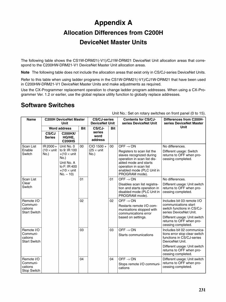
Appendix AAllocation Differences from C200H
DeviceNet Master Units
The following table shows the CS1W-DRM21(-V1)/CJ1W-DRM21 DeviceNet Unit allocation areas that corre-spond to the C200HW-DRM21-V1 DeviceNet Master Unit allocation areas.
Note The following table does not include the allocation areas that exist only in CS/CJ-series DeviceNet Units.
Refer to this table when using ladder programs in the CS1W-DRM21(-V1)/CJ1W-DRM21 that have been usedin C200HW-DRM21-V1 DeviceNet Master Units and make adjustments as required.
Use the CX-Programmer replacement operation to change ladder program addresses. When using a CX-Pro-grammer Ver. 1.2 or earlier, use the global replace utility function to globally replace addresses.
Software SwitchesUnit No.: Set on rotary switches on front panel (0 to 15).
Name C200H DeviceNet Master Unit
CS/CJ-series DeviceNet Unit
Contents for CS/CJ-series DeviceNet Unit
Differences from C200H-series DeviceNet Master
UnitWord address Bit CS/CJ-series word
address
Bit
CS/CJ Series
C200HX/ HG/HE, C200HS
Scan List Enable Switch
IR 2000 + (10 × unit No.)
Unit No. 0 to 9: IR 100 +(10 × unit No.)Unit No. A to F: IR 400 +(10 × unit No. – 10)
00 CIO 1500 + (25 × unit No.)
00 OFF → ONRegisters to scan list the slaves recognized during operation in scan list dis-abled mode and starts operation in scan list enabled mode (PLC Unit in PROGRAM mode).
No differences.Different usage: Switch returns to OFF when pro-cessing completed.
Scan List Clear Switch
01 01 OFF → ON
Disables scan list registra-tion and starts operation in disabled mode (PLC Unit in PROGRAM mode).
No differences.
Different usage: Unit switch returns to OFF when pro-cessing completed.
Remote I/O Communi-cations Start Switch
02 02 OFF → ON
Restarts remote I/O com-munications stopped with communications error based on settings.
Includes bit 03 remote I/O communications start switch functions in CS/CJ-series DeviceNet Unit.
Different usage: Unit switch returns to OFF when pro-cessing completed.
Remote I/O Communi-cations Start Switch
03 03 OFF → ONStarts communications
Includes bit 02 communica-tions error stop clear switch functions in CS/CJ-series DeviceNet Unit.Different usage: Unit switch returns to OFF when pro-cessing completed.
Remote I/O Communi-cations Stop Switch
04 04 OFF → ON
Stops remote I/O communi-cations
Different usage: Unit switch returns to OFF when pro-cessing completed.
231
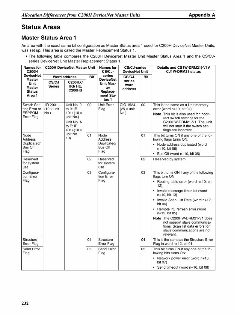
Allocation Differences from C200H DeviceNet Master Units Appendix A
Status Areas
Master Status Area 1An area with the exact same bit configuration as Master Status area 1 used for C200H DeviceNet Master Units,was set up. This area is called the Master Replacement Status 1.
• The following table compares the C200H DeviceNet Master Unit Master Status Area 1 and the CS/CJ-series DeviceNet Unit Master Replacement Status 1.
Names for C200H
DeviceNet Master
Unit Master Status Area 1
C200H DeviceNet Master Unit Names for CS/CJ-series
DeviceNet Unit Mas-
ter Replace-ment Sta-
tus 1
CS/CJ-series DeviceNet Unit
Details and CS1W-DRM21(-V1)/CJ1W-DRM21 status
Word address Bit CS/CJ-series word
address
Bit
CS/CJ Series
C200HX/HG/ HE, C200HS
Switch Set-ting Error or EEPROM Error Flag
IR 2001+ (10 × unit No.)
Unit No. 0 to 9: IR 101+(10 × unit No.)
Unit No. A to F: IR 401+(10 × unit No. – 10)
00 Unit Error Flag
CIO 1524+ (25 × unit No.)
00 This is the same as a Unit memory error (word n+10, bit 04).Note This bit is also used for incor-
rect switch settings for the C200HW-DRM21-V1. The Unit will not start if the switch set-tings are incorrect.
Node Address Duplicated/Bus Off Flag
01 Node Address Duplicated/Bus Off Flag
01 This bit turns ON if any one of the fol-lowing flags turns ON:• Node address duplicated (word
n+10, bit 06)• Bus Off (word n+10, bit 05)
Reserved for system use
02 Reserved for system use
02 Reserved by system
Configura-tion Error Flag
03 Configura-tion Error Flag
03 This bit turns ON if any of the following flags turn ON:• Routing table error (word n+10, bit
12)• Invalid message timer list (word
n+10, bit 13)• Invalid Scan List Data (word n+12,
bit 04)
• Remote I/O refresh error (word n+12, bit 05)
Note The C200HW-DRM21-V1 does not support slave communica-tions. Scan list data errors for slave communications are not relevant.
Structure Error Flag
04 Structure Error Flag
04 This is the same as the Structure Error Flag in word n+12, bit 01.
Send Error Flag
05 Send Error Flag
05 This bit turns ON if any one of the fol-lowing bits turns ON:
• Network power error (word n+10, bit 07)
• Send timeout (word n+10, bit 08)
232
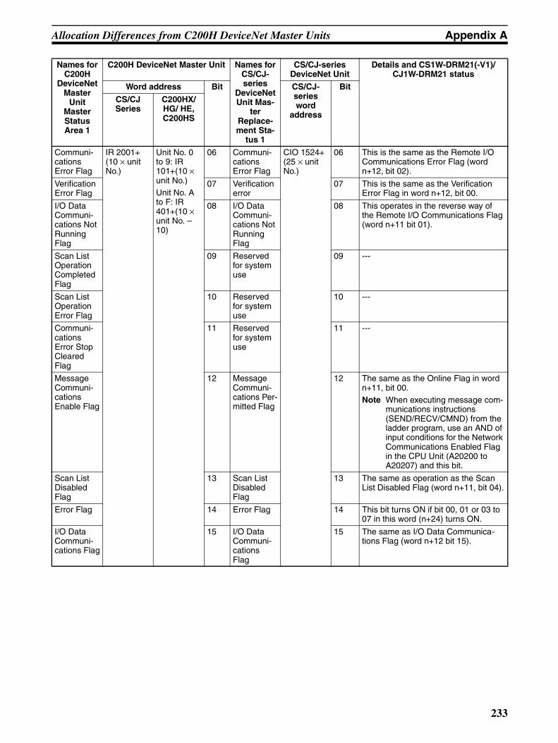
Allocation Differences from C200H DeviceNet Master Units Appendix A
Communi-cations Error Flag
IR 2001+ (10 × unit No.)
Unit No. 0 to 9: IR 101+(10 × unit No.)Unit No. A to F: IR 401+(10 × unit No. – 10)
06 Communi-cations Error Flag
CIO 1524+ (25 × unit No.)
06 This is the same as the Remote I/O Communications Error Flag (word n+12, bit 02).
Verification Error Flag
07 Verification error
07 This is the same as the Verification Error Flag in word n+12, bit 00.
I/O Data Communi-cations Not Running Flag
08 I/O Data Communi-cations Not Running Flag
08 This operates in the reverse way of the Remote I/O Communications Flag (word n+11 bit 01).
Scan List Operation Completed Flag
09 Reserved for system use
09 ---
Scan List Operation Error Flag
10 Reserved for system use
10 ---
Communi-cations Error Stop Cleared Flag
11 Reserved for system use
11 ---
Message Communi-cations Enable Flag
12 Message Communi-cations Per-mitted Flag
12 The same as the Online Flag in word n+11, bit 00.Note When executing message com-
munications instructions (SEND/RECV/CMND) from the ladder program, use an AND of input conditions for the Network Communications Enabled Flag in the CPU Unit (A20200 to A20207) and this bit.
Scan List Disabled Flag
13 Scan List Disabled Flag
13 The same as operation as the Scan List Disabled Flag (word n+11, bit 04).
Error Flag 14 Error Flag 14 This bit turns ON if bit 00, 01 or 03 to 07 in this word (n+24) turns ON.
I/O Data Communi-cations Flag
15 I/O Data Communi-cations Flag
15 The same as I/O Data Communica-tions Flag (word n+12 bit 15).
Names for C200H
DeviceNet Master
Unit Master Status Area 1
C200H DeviceNet Master Unit Names for CS/CJ-series
DeviceNet Unit Mas-
ter Replace-ment Sta-
tus 1
CS/CJ-series DeviceNet Unit
Details and CS1W-DRM21(-V1)/CJ1W-DRM21 status
Word address Bit CS/CJ-series word
address
Bit
CS/CJ Series
C200HX/HG/ HE, C200HS
233
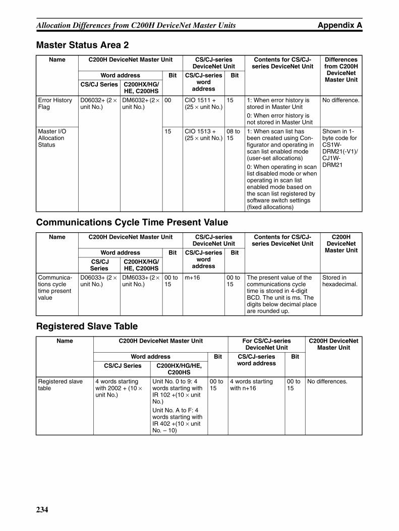
Allocation Differences from C200H DeviceNet Master Units Appendix A
Master Status Area 2
Communications Cycle Time Present Value
Registered Slave Table
Name C200H DeviceNet Master Unit CS/CJ-series DeviceNet Unit
Contents for CS/CJ-series DeviceNet Unit
Differences from C200H DeviceNet
Master UnitWord address Bit CS/CJ-series
word address
Bit
CS/CJ Series C200HX/HG/HE, C200HS
Error History Flag
D06032+ (2 × unit No.)
DM6032+ (2 × unit No.)
00 CIO 1511 + (25 × unit No.)
15 1: When error history is stored in Master Unit0: When error history is not stored in Master Unit
No difference.
Master I/O Allocation Status
15 CIO 1513 + (25 × unit No.)
08 to 15
1: When scan list has been created using Con-figurator and operating in scan list enabled mode (user-set allocations)
0: When operating in scan list disabled mode or when operating in scan list enabled mode based on the scan list registered by software switch settings (fixed allocations)
Shown in 1-byte code for CS1W- DRM21(-V1)/CJ1W-DRM21
Name C200H DeviceNet Master Unit CS/CJ-series DeviceNet Unit
Contents for CS/CJ-series DeviceNet Unit
C200H DeviceNet
Master UnitWord address Bit CS/CJ-series word
address
Bit
CS/CJ Series
C200HX/HG/HE, C200HS
Communica-tions cycle time present value
D06033+ (2 × unit No.)
DM6033+ (2 × unit No.)
00 to 15
m+16 00 to 15
The present value of the communications cycle time is stored in 4-digit BCD. The unit is ms. The digits below decimal place are rounded up.
Stored in hexadecimal.
Name C200H DeviceNet Master Unit For CS/CJ-series DeviceNet Unit
C200H DeviceNet Master Unit
Word address Bit CS/CJ-series word address
Bit
CS/CJ Series C200HX/HG/HE, C200HS
Registered slave table
4 words starting with 2002 + (10 × unit No.)
Unit No. 0 to 9: 4 words starting with IR 102 +(10 × unit No.)
Unit No. A to F: 4 words starting with IR 402 +(10 × unit No. – 10)
00 to 15
4 words starting with n+16
00 to 15
No differences.
234
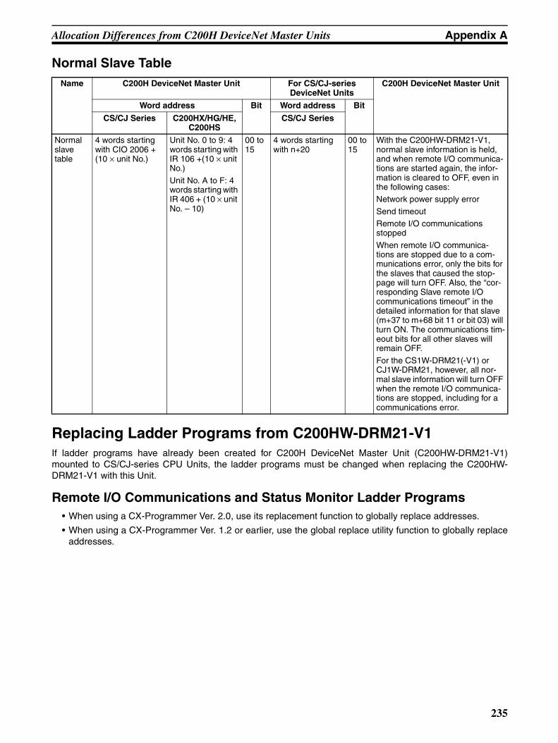
Allocation Differences from C200H DeviceNet Master Units Appendix A
Normal Slave Table
Replacing Ladder Programs from C200HW-DRM21-V1If ladder programs have already been created for C200H DeviceNet Master Unit (C200HW-DRM21-V1)mounted to CS/CJ-series CPU Units, the ladder programs must be changed when replacing the C200HW-DRM21-V1 with this Unit.
Remote I/O Communications and Status Monitor Ladder Programs• When using a CX-Programmer Ver. 2.0, use its replacement function to globally replace addresses.
• When using a CX-Programmer Ver. 1.2 or earlier, use the global replace utility function to globally replaceaddresses.
Name C200H DeviceNet Master Unit For CS/CJ-series DeviceNet Units
C200H DeviceNet Master Unit
Word address Bit Word address Bit
CS/CJ Series C200HX/HG/HE, C200HS
CS/CJ Series
Normal slave table
4 words starting with CIO 2006 + (10 × unit No.)
Unit No. 0 to 9: 4 words starting with IR 106 +(10 × unit No.)
Unit No. A to F: 4 words starting with IR 406 + (10 × unit No. – 10)
00 to 15
4 words starting with n+20
00 to 15
With the C200HW-DRM21-V1, normal slave information is held, and when remote I/O communica-tions are started again, the infor-mation is cleared to OFF, even in the following cases:Network power supply error
Send timeoutRemote I/O communications stopped
When remote I/O communica-tions are stopped due to a com-munications error, only the bits for the slaves that caused the stop-page will turn OFF. Also, the “cor-responding Slave remote I/O communications timeout” in the detailed information for that slave (m+37 to m+68 bit 11 or bit 03) will turn ON. The communications tim-eout bits for all other slaves will remain OFF.
For the CS1W-DRM21(-V1) or CJ1W-DRM21, however, all nor-mal slave information will turn OFF when the remote I/O communica-tions are stopped, including for a communications error.
235

Allocation Differences from C200H DeviceNet Master Units Appendix A
Replace the addresses as shown in the following table.
Message Communications in Ladder Programs
Note If there is a routing table in the CS/CJ-series CPU Unit, the DeviceNet Unit must be registered in it whenreplacing the C200HW-DRM21-V1 with the CS1W-DRM21(-V1) or CJ1W-DRM21. If the DeviceNet Unitis not registered, it will result in a routing table error, and the 7-segment display of the DeviceNet Unit willindicate “HC”.
Area type C200HW-DRM21-V1 This Unit (CS1W-DRM21(-V1))
Remarks
First word of IN area in fixed remote I/O alloca-tions
IR 350 Can be allocated to CIO 350 from Config-urator or in allocated DM Area words
Completely compati-ble.
First word of OUT area in fixed remote I/O alloca-tions
Word 50 Can be allocated to CIO 50 from Configu-rator or in allocated DM Area words
Completely compati-ble.
Software switches IR 2000 +10 × unit No.
CIO 1500 +25 × unit No.
Only word address changed.
Communications error stop clear Bit 02 Bit 02
Remote I/O communications start Bit 03 Bit 03
Remote I/O communications stop Bit 04 Bit 04
Master status area 1 IR 2000 +10 × unit No.+ 1
CIO 1500 +25 × unit No.+ 24
Only word address changed.
Master status area 2 Scan list registration by Configurator
D06032+2 × unit No.+1, bit 15
CIO 1500 +25 × unit No.+ 13Note Allocated as status code.
Cannot be accessed from ladder program.
Error history D06032+2 × unit No.+1, bit 00
CIO 1500 +25 × unit No.+bit 15 of 11
First word of registered slave table IR 2000 +10 × unit No.+2
CIO 1500 +25 × unit No.+16
Only word address changed.
First word of normal slave table IR 2000 +10 × unit No.+6
CIO 1500 +25 × unit No.+20
Only word address changed.
Instructions C200HW-DRM21-V1 This Unit (CS1W-DRM21(-V1))
Remarks
Message communica-tions instructions
IOWR instructions CMND instructions (SEND/RECV also possi-ble for FINS data commu-nications)
Change instructions and message data.
Instruction execution con-ditions
Message Communica-tions Enabled Flag (IR 2000 +10 × unit No.+ 1, bit 12)
AND condition for 1. Mes-sage Communications Permitted Flag (CIO 1500 +25 × unit No.+24, bit 12) and
2. Network Communica-tions Enabled Flag (A20200 to A20207: Cor-respond to ports 0 to 7)
Change execution conditions.Note The Message Communications Permitted Flag (CIO 1500 +25 × unit No.+ 24, bit 12) is the same even when online as (CIO 1500 +25 × unit No.+ 11, bit 00)
236
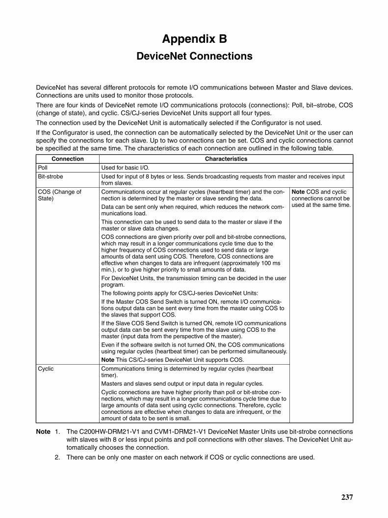
Appendix BDeviceNet Connections
DeviceNet has several different protocols for remote I/O communications between Master and Slave devices.Connections are units used to monitor those protocols.
There are four kinds of DeviceNet remote I/O communications protocols (connections): Poll, bit–strobe, COS(change of state), and cyclic. CS/CJ-series DeviceNet Units support all four types.
The connection used by the DeviceNet Unit is automatically selected if the Configurator is not used.
If the Configurator is used, the connection can be automatically selected by the DeviceNet Unit or the user canspecify the connections for each slave. Up to two connections can be set. COS and cyclic connections cannotbe specified at the same time. The characteristics of each connection are outlined in the following table.
Note 1. The C200HW-DRM21-V1 and CVM1-DRM21-V1 DeviceNet Master Units use bit-strobe connectionswith slaves with 8 or less input points and poll connections with other slaves. The DeviceNet Unit au-tomatically chooses the connection.
2. There can be only one master on each network if COS or cyclic connections are used.
Connection Characteristics
Poll Used for basic I/O.
Bit-strobe Used for input of 8 bytes or less. Sends broadcasting requests from master and receives input from slaves.
COS (Change of State)
Communications occur at regular cycles (heartbeat timer) and the con-nection is determined by the master or slave sending the data.Data can be sent only when required, which reduces the network com-munications load.
This connection can be used to send data to the master or slave if the master or slave data changes. COS connections are given priority over poll and bit-strobe connections, which may result in a longer communications cycle time due to the higher frequency of COS connections used to send data or large amounts of data sent using COS. Therefore, COS connections are effective when changes to data are infrequent (approximately 100 ms min.), or to give higher priority to small amounts of data.
For DeviceNet Units, the transmission timing can be decided in the user program.The following points apply for CS/CJ-series DeviceNet Units:
If the Master COS Send Switch is turned ON, remote I/O communica-tions output data can be sent every time from the master using COS to the slaves that support COS.
If the Slave COS Send Switch is turned ON, remote I/O communications output data can be sent every time from the slave using COS to the master (input data from the perspective of the master).
Even if the software switch is not turned ON, the COS communications using regular cycles (heartbeat timer) can be performed simultaneously.Note This CS/CJ-series DeviceNet Unit supports COS.
Note COS and cyclic connections cannot be used at the same time.
Cyclic Communications timing is determined by regular cycles (heartbeat timer).Masters and slaves send output or input data in regular cycles.
Cyclic connections are have higher priority than poll or bit-strobe con-nections, which may result in a longer communications cycle time due to large amounts of data sent using cyclic connections. Therefore, cyclic connections are effective when changes to data are infrequent, or the amount of data to be sent is small.
237
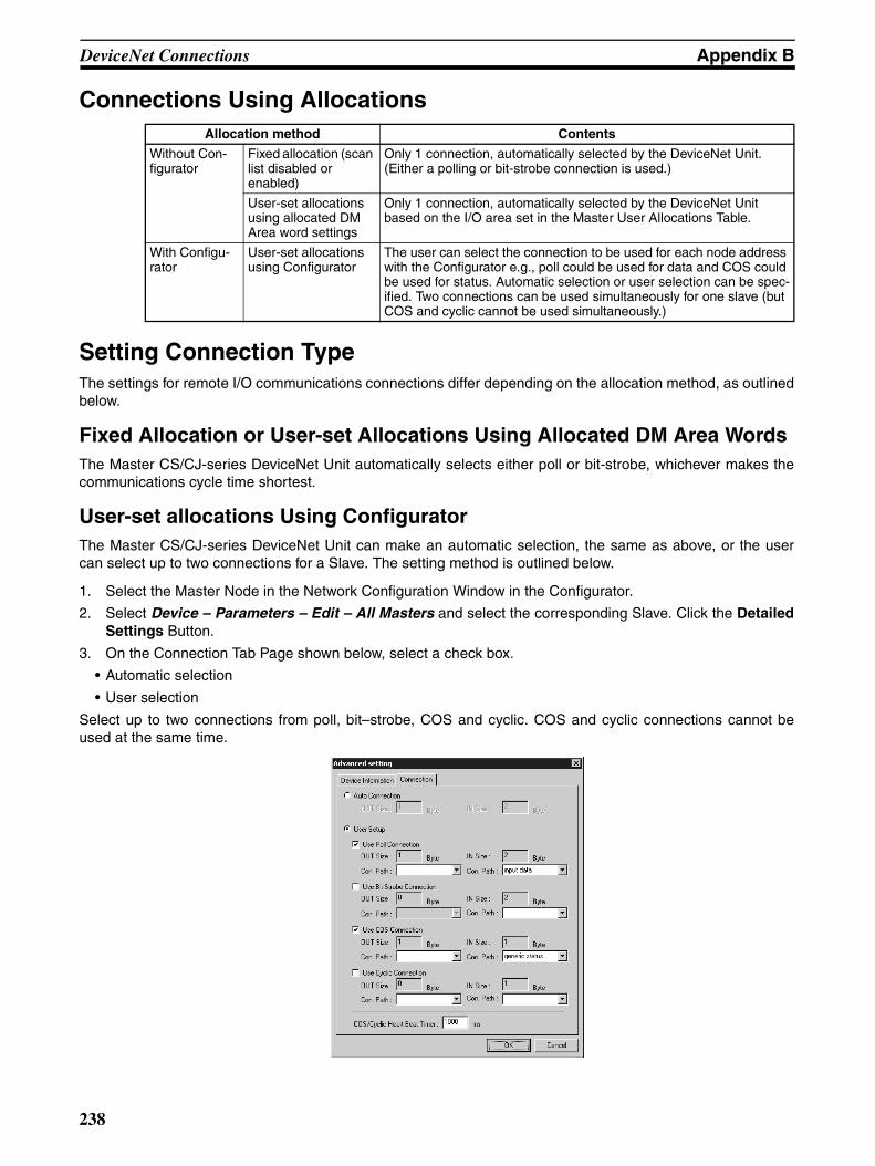
DeviceNet Connections Appendix B
Connections Using Allocations
Setting Connection TypeThe settings for remote I/O communications connections differ depending on the allocation method, as outlinedbelow.
Fixed Allocation or User-set Allocations Using Allocated DM Area WordsThe Master CS/CJ-series DeviceNet Unit automatically selects either poll or bit-strobe, whichever makes thecommunications cycle time shortest.
User-set allocations Using ConfiguratorThe Master CS/CJ-series DeviceNet Unit can make an automatic selection, the same as above, or the usercan select up to two connections for a Slave. The setting method is outlined below.
1. Select the Master Node in the Network Configuration Window in the Configurator.
2. Select Device – Parameters – Edit – All Masters and select the corresponding Slave. Click the DetailedSettings Button.
3. On the Connection Tab Page shown below, select a check box.
• Automatic selection
• User selection
Select up to two connections from poll, bit–strobe, COS and cyclic. COS and cyclic connections cannot beused at the same time.
Allocation method Contents
Without Con-figurator
Fixed allocation (scan list disabled or enabled)
Only 1 connection, automatically selected by the DeviceNet Unit. (Either a polling or bit-strobe connection is used.)
User-set allocations using allocated DM Area word settings
Only 1 connection, automatically selected by the DeviceNet Unit based on the I/O area set in the Master User Allocations Table.
With Configu-rator
User-set allocations using Configurator
The user can select the connection to be used for each node address with the Configurator e.g., poll could be used for data and COS could be used for status. Automatic selection or user selection can be spec-ified. Two connections can be used simultaneously for one slave (but COS and cyclic cannot be used simultaneously.)
238

DeviceNet Connections Appendix B
Note 1. Output data using poll connections and output data using COS or cyclic connections are transmittedusing the same frame. Therefore set the same output size (bytes) when combining poll and COS orpoll and cyclic.
2. The COS/cyclic heartbeat timer is the smallest transmission interval for COS or cyclic connections.It can be set for each corresponding slave.
Refer to DeviceNet Configurator Operation Manual (W382) for details on Configurator operation.
Connection PathConnection path are parameters that specify the type of I/O data in the slaves. Depending on the type of slave,the internal I/O data type may be able to be selected. If it can, the connection path and I/O data type in theslave specified for remote I/O communications.
The connection path settings will differ depending on the allocation method, as outlined below.
Fixed Allocation or User-set Allocations Using DMConnection path settings cannot be made.
User-set Allocations Using ConfiguratorThe Configurator can be used to set the type of I/O data in the slave, using the connection path. The user canuse this method to set the I/O data type in the master and the remote I/O communications slave.
The connection path is saved by the Configurator to the CS/CJ-series DeviceNet Unit scan list and when theremote I/O communications are started, the connection path is set to the slave via the DeviceNet network.
Master
I/O data
Connection
Connection pathSlave
Data 1 Data 2
239
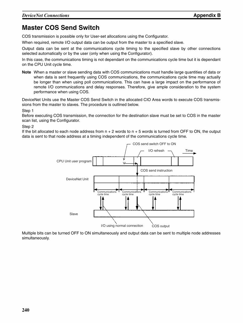
DeviceNet Connections Appendix B
Master COS Send SwitchCOS transmission is possible only for User-set allocations using the Configurator.
When required, remote I/O output data can be output from the master to a specified slave.
Output data can be sent at the communications cycle timing to the specified slave by other connectionsselected automatically or by the user (only when using the Configurator).
In this case, the communications timing is not dependant on the communications cycle time but it is dependanton the CPU Unit cycle time.
Note When a master or slave sending data with COS communications must handle large quantities of data orwhen data is sent frequently using COS communications, the communications cycle time may actuallybe longer than when using poll communications. This can have a large impact on the performance ofremote I/O communications and delay responses. Therefore, give ample consideration to the systemperformance when using COS.
DeviceNet Units use the Master COS Send Switch in the allocated CIO Area words to execute COS transmis-sions from the master to slaves. The procedure is outlined below.
Step 1Before executing COS transmission, the connection for the destination slave must be set to COS in the masterscan list, using the Configurator.
Step 2If the bit allocated to each node address from n + 2 words to n + 5 words is turned from OFF to ON, the outputdata is sent to that node address at a timing independent of the communications cycle time.
Multiple bits can be turned OFF to ON simultaneously and output data can be sent to multiple node addressessimultaneously.
CPU Unit user program
DeviceNet Unit
Slave
COS send switch OFF to ON
I/O refresh Time
COS send instruction
I/O using normal connection COS output
Communications cycle time
Communications cycle time
Communications cycle time
Communications cycle time
240
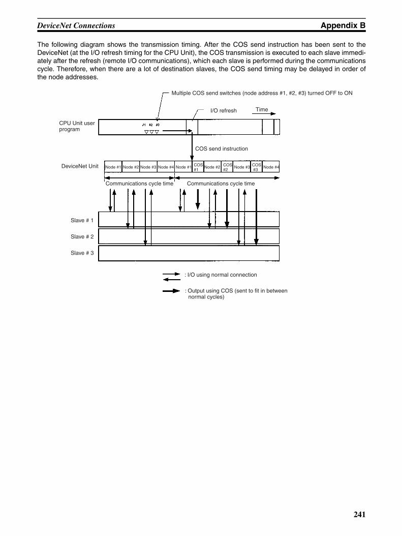
DeviceNet Connections Appendix B
The following diagram shows the transmission timing. After the COS send instruction has been sent to theDeviceNet (at the I/O refresh timing for the CPU Unit), the COS transmission is executed to each slave immedi-ately after the refresh (remote I/O communications), which each slave is performed during the communicationscycle. Therefore, when there are a lot of destination slaves, the COS send timing may be delayed in order ofthe node addresses.
DeviceNet Unit
Multiple COS send switches (node address #1, #2, #3) turned OFF to ON
I/O refresh Time
COS send instruction
Node #1 Node #2 Node #3 Node #4 Node #1 COS #1
Node #2 COS #2
Node #3 COS #3
Node #4
Communications cycle time Communications cycle time
Slave # 1
Slave # 2
Slave # 3
: I/O using normal connection
: Output using COS (sent to fit in between normal cycles)
CPU Unit user program
241

Appendix CFINS Commands and Responses for
DeviceNet Units
List of Command Codes
Refer to SYSMAC CS/CJ Series Communication Commands Reference Man-ual (W342) for details on end codes.
RESET (0403)Resets (restarts) the DeviceNet Unit.
Command BlockResets the DeviceNet Unit.
Response BlockThere are no responses for this command
End Code
Explanation• Resets the DeviceNet Unit.
• A communications error has occurred at the Slave but the Slave willrestore after the DeviceNet Unit has started up.
• The remote device communicating the message may have timed out butcommunications can be performed normally after the DeviceNet Unit hasstarted up.
READ CONTROLLER INFORMATION (0501)Reads the following DeviceNet Unit information.
• Model
• Version
• Node address
Command type Command code Reference page
RESET 0403 243
CONTROLLER DATA READ 0501 243
CONTROLLER STATUS READ 0601 244
ECHOBACK TEST 0801 245
ERROR LOG READ 2102 246
ERROR LOG CLEAR 2103 247
End code (hex) Contents
1001 The command length exceeds maximum command length.
Command code
243

FINS Commands and Responses for DeviceNet Units Appendix C
• Baud rate
Command Block
Response Block
End Codes
Parameter Details[Model, Version] (Response)The DeviceNet Unit model and version are returned as outlined below in 20-byte ASCII code. If the data is less than 20 bytes, the remaining bytes will befilled by 20 Hex (space).
• Model:CS1W-DRM21@@@@@@@@@@ (@: space)Or: CJ1W-DRM21@@@@@@@@@@ (@: space)Version:V1.00V1.02V1.01@@@@@ (@: space)
• Node Address:The following DeviceNet Unit node addresses are returned: 00 to 3F hex.
• Baud Rate:0 hex: 125 kbps1 hex: 250 kbps2 hex: 500 kbps
READ CONTROLLER STATUS (0601)Reads the internal status of the DeviceNet Unit.
Command Block
End code (hex) Contents
0000 Normal end
1001 Command length exceeds maximum command length.
Command code
05 01 20 bytes 20 bytes
Command code
End code Model Version Node address
Baud rate
Command code
244

FINS Commands and Responses for DeviceNet Units Appendix C
Response Block
End Codes
Parameter Details[Operation status, Units status 1, Unit status 2, Master function status 1, Mas-ter function status 2, Slave function status 1, Slave function status 2](response)
• Operation StatusFixed at 01 hex.
• Units status 1, Unit status 2, Master function status 1, Master function sta-tus 2, Slave function status 1, Slave function status 2The same value as the status in the allocated CIO Area words is returned.
ECHOBACK TEST (0801)Performs an echo back test (communications test between nodes) betweenspecified nodes.
Command Block
Response Block
End Codes
Parameter Details[Test Data] (Command, Response)
End code (hex) Contents
0000 Normal end
1001 Command length exceeds maximum command length.
2606 Service cannot be executed.
End code (hex) Contents
0000 Normal end
1001 Command length exceeds maximum command length.
1002 The command length is insufficient for the smallest command.
There is no test data.
Command code
End code Operation status
Unit status 1
Unit status 2
Master function status 1
Master function status 2
Slave function status 1
Slave function status 2
Command code
Test data
538 bytes max.
Command code
End code Test data
538 bytes max.
245
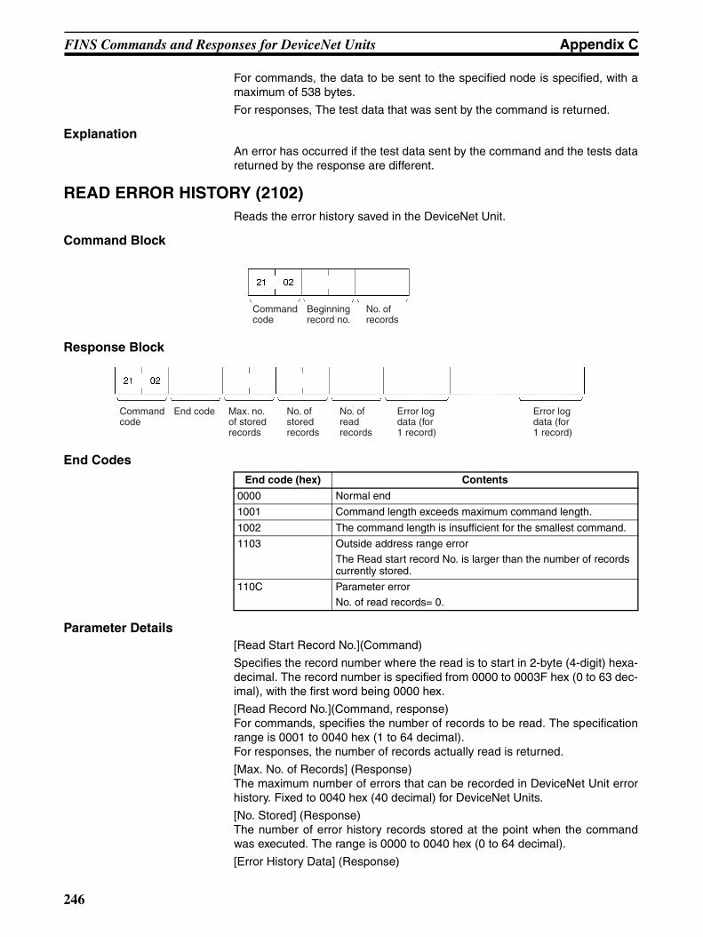
FINS Commands and Responses for DeviceNet Units Appendix C
For commands, the data to be sent to the specified node is specified, with amaximum of 538 bytes.
For responses, The test data that was sent by the command is returned.
ExplanationAn error has occurred if the test data sent by the command and the tests datareturned by the response are different.
READ ERROR HISTORY (2102)Reads the error history saved in the DeviceNet Unit.
Command Block
Response Block
End Codes
Parameter Details[Read Start Record No.](Command)
Specifies the record number where the read is to start in 2-byte (4-digit) hexa-decimal. The record number is specified from 0000 to 0003F hex (0 to 63 dec-imal), with the first word being 0000 hex.
[Read Record No.](Command, response)For commands, specifies the number of records to be read. The specificationrange is 0001 to 0040 hex (1 to 64 decimal).For responses, the number of records actually read is returned.
[Max. No. of Records] (Response)The maximum number of errors that can be recorded in DeviceNet Unit errorhistory. Fixed to 0040 hex (40 decimal) for DeviceNet Units.
[No. Stored] (Response)The number of error history records stored at the point when the commandwas executed. The range is 0000 to 0040 hex (0 to 64 decimal).
[Error History Data] (Response)
End code (hex) Contents
0000 Normal end
1001 Command length exceeds maximum command length.
1002 The command length is insufficient for the smallest command.
1103 Outside address range error
The Read start record No. is larger than the number of records currently stored.
110C Parameter error
No. of read records= 0.
Command code
Beginning record no.
No. of records
Command code
End code Max. no. of stored records
No. of stored records
No. of read records
Error log data (for 1 record)
Error log data (for 1 record)
246
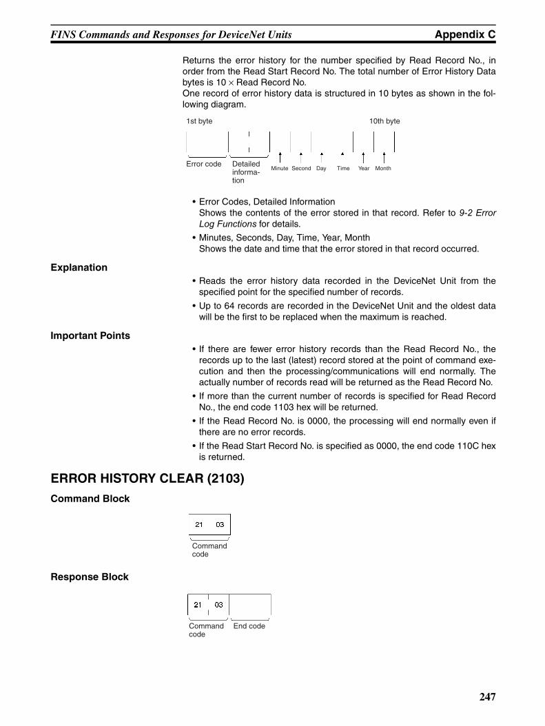
FINS Commands and Responses for DeviceNet Units Appendix C
Returns the error history for the number specified by Read Record No., inorder from the Read Start Record No. The total number of Error History Databytes is 10 × Read Record No.One record of error history data is structured in 10 bytes as shown in the fol-lowing diagram.
• Error Codes, Detailed InformationShows the contents of the error stored in that record. Refer to 9-2 ErrorLog Functions for details.
• Minutes, Seconds, Day, Time, Year, MonthShows the date and time that the error stored in that record occurred.
Explanation• Reads the error history data recorded in the DeviceNet Unit from the
specified point for the specified number of records.
• Up to 64 records are recorded in the DeviceNet Unit and the oldest datawill be the first to be replaced when the maximum is reached.
Important Points• If there are fewer error history records than the Read Record No., the
records up to the last (latest) record stored at the point of command exe-cution and then the processing/communications will end normally. Theactually number of records read will be returned as the Read Record No.
• If more than the current number of records is specified for Read RecordNo., the end code 1103 hex will be returned.
• If the Read Record No. is 0000, the processing will end normally even ifthere are no error records.
• If the Read Start Record No. is specified as 0000, the end code 110C hexis returned.
ERROR HISTORY CLEAR (2103)
Command Block
Response Block
Error code Detailed informa-tion
Minute Second Time Year MonthDay
1st byte 10th byte
Command code
Command code
End code
247

FINS Commands and Responses for DeviceNet Units Appendix C
End Codes
Important PointThe Error History Clear command clears the RAM and EEP-ROM error his-tory tables.
End code (hex) Contents
0000 Normal end
1001 Command length exceeds maximum command length.
248
Appendix DMulti-vendor Applications
This appendix provides precautions and reference material needed when using DeviceNet (CompoBus/D)Units as DeviceNet components in a multi-vendor environment.
Connecting another Company’s Slaves to an OMRON MasterIf a Slave has an EDS file, it can be installed in OMRON’s Configurator to enable handling it just like anOMRON Slave. (OMRON’s Configurator already has installed all of the Slave EDS files currently registeredwith the ODVA.)
In particular, be sure to determine the number of words in the OMRON Master Unit that the Slave requires forinput and output.
For Connection Object Interface 2 (Polled I/O Connection), the number of I/O words allocated in the OMRONMaster can be found from the “Produced Connection Size” and “Consumed Connection Size” as shown below.Up to 32 words can be allocated to inputs and another 32 words to outputs.
Produced Connection SizeThis is the amount of memory (usually in bytes) allocated as input.
Consumed Connection SizeThis is the amount of memory (usually in bytes) allocated as output.
If the connection size is an even number of bytes, the number of allocated words is: (bytes ÷ 2).
If the connection size is an odd number of bytes, the number of allocated words is: [(bytes +1) ÷ 2)].
If the connections size is zero (0), no words are allocated.
For Connection Object Interface 3 (Bit Strobed I/O Connection), the number of input words allocated in theOMRON Master can be found from the “Produced Connection Size” as shown below.
Produced Connection SizeThis is the amount of memory (usually in bytes) allocated as input.
If the connection size is an even number of bytes, the number of allocated words is: (bytes ÷ 2).
If the connection size is an odd number of bytes, the number of allocated words is: [(bytes +1) ÷ 2)].
Connecting an OMRON Slave to another Company’s ConfiguratorWhen another company’s configurator (a device that makes environment settings on DeviceNet Masters andSlaves) is connected, it will be able to read settings from OMRON Masters and Slaves but not change them.
When another company’s configurator is being used, we recommend creating an OMRON Slave EDS file (a filethat contains each Slave’s parameters and operating information). Refer to the OMRON Slave device profile aswell as the Configurator’s manual for details on creating an EDS file.
249
Multi-vendor Applications Appendix D
Master Unit Device Profile
Object Mounting
Identity Object (01 Hex)
Message Router Object (02 Hex)
General data Compatible DeviceNet Specifications Volume I - Release 2.0Volume II - Release 2.0
Vendor name OMRON Corporation Vendor ID = 47
Device profile name Communication Adapter Profile number = 12
Manufacturer catalog number Manual number (W267, W347)
Manufacturer revision 1.1
Physical conform-ance data
Network current consumption 24 VDC, 30 mA max.
Connector type Open plug
Physical insulation Yes
Supported indicators Module, Network
MAC ID setting Rotary switch
Default MAC ID 63
Baud rate setting DIP switch
Supported baud rates 125 kbps, 250 kbps, and 500 kbps
Communications data
Predefined Master/Slave connection set Group 2 clientGroup 2 only clientGroup 2 server
Dynamic connection support (UCMM) Yes
Explicit message fragmentation support Yes
Object class Attribute Not supported
Service Not supported
Item ID content Get (read) Set (write) Value
Object instance Attribute 1 Vendor Yes No 47
2 Product type Yes No 12
3 Product code Yes No CS1W-DRT21: 02CJ1W-DRT21: 05
4 Revision Yes No 1.1
5 Status (bits supported) Yes No ---
6 Serial number Yes No Unique for each Unit
7 Product name Yes No CS1W-DRM21 or CJ1W-DRM21
8 State No No ---
Service DeviceNet Service Parameter option
05 Reset None
0E Get Attribute Single None
Object class Attribute Not supported
Service Not supported
Object instance Attribute Not supported
Service Not supported
Vendor specification addition No
250
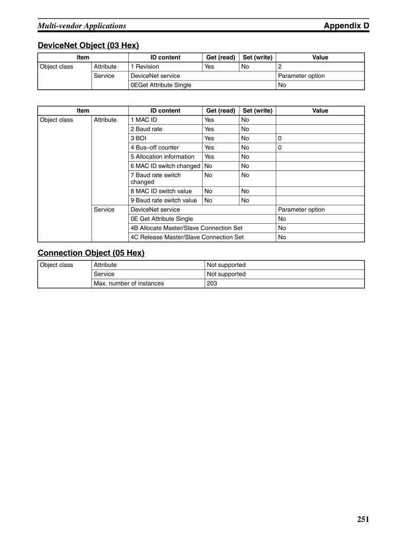
Multi-vendor Applications Appendix D
DeviceNet Object (03 Hex)
Connection Object (05 Hex)
Item ID content Get (read) Set (write) Value
Object class Attribute 1 Revision Yes No 2
Service DeviceNet service Parameter option
0EGet Attribute Single No
Item ID content Get (read) Set (write) Value
Object class Attribute 1 MAC ID Yes No
2 Baud rate Yes No
3 BOI Yes No 0
4 Bus–off counter Yes No 0
5 Allocation information Yes No
6 MAC ID switch changed No No
7 Baud rate switch changed
No No
8 MAC ID switch value No No
9 Baud rate switch value No No
Service DeviceNet service Parameter option
0E Get Attribute Single No
4B Allocate Master/Slave Connection Set No
4C Release Master/Slave Connection Set No
Object class Attribute Not supported
Service Not supported
Max. number of instances 203
251

Multi-vendor Applications Appendix D
Object instance 1 Section Information Max. No. of instances
Instance type
Explicit Message 1
Produc-tion trig-ger
Cyclic
Transport type
Server
Transport class
3
Attribute ID content Get (read)
Set (write)
Value
1 State Yes No ---
2 Instance type Yes No 0
3 Transport class trigger Yes No 83 hex
4 Produced connection ID Yes No ---
5 Consumed connection ID Yes No ---
6 Initial comm. characteristics Yes No 21 hex
7 Produced connection size Yes No 553
8 Consumed connection size Yes No Format 16-16: 557Format 8-8: 555Format 16-8, 8-16: 556
9 Expected packed rate Yes Yes ---
12 Watchdog time-out action Yes No 1 or 3
13 Produced connection path length Yes No 0
14 Produced connection path Yes No empty
15 Consumed connection path length Yes No 0
16 Consumed connection path Yes No empty
17 Production inhibit time Yes Yes ---
Service DeviceNet service Parameter option
05 Reset No
0E Get Attribute Single No
10 Set Attribute Single No
252
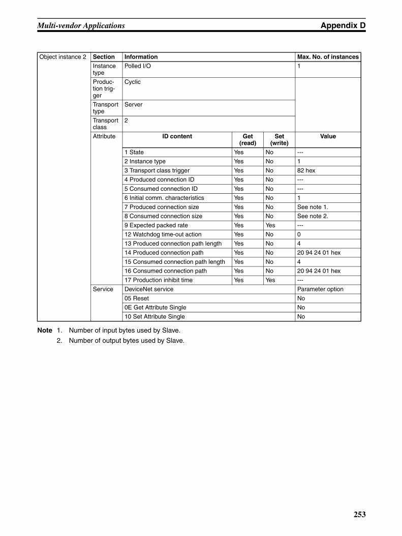
Multi-vendor Applications Appendix D
Note 1. Number of input bytes used by Slave.
2. Number of output bytes used by Slave.
Object instance 2 Section Information Max. No. of instances
Instance type
Polled I/O 1
Produc-tion trig-ger
Cyclic
Transport type
Server
Transport class
2
Attribute ID content Get (read)
Set (write)
Value
1 State Yes No ---
2 Instance type Yes No 1
3 Transport class trigger Yes No 82 hex
4 Produced connection ID Yes No ---
5 Consumed connection ID Yes No ---
6 Initial comm. characteristics Yes No 1
7 Produced connection size Yes No See note 1.
8 Consumed connection size Yes No See note 2.
9 Expected packed rate Yes Yes ---
12 Watchdog time-out action Yes No 0
13 Produced connection path length Yes No 4
14 Produced connection path Yes No 20 94 24 01 hex
15 Consumed connection path length Yes No 4
16 Consumed connection path Yes No 20 94 24 01 hex
17 Production inhibit time Yes Yes ---
Service DeviceNet service Parameter option
05 Reset No
0E Get Attribute Single No
10 Set Attribute Single No
253
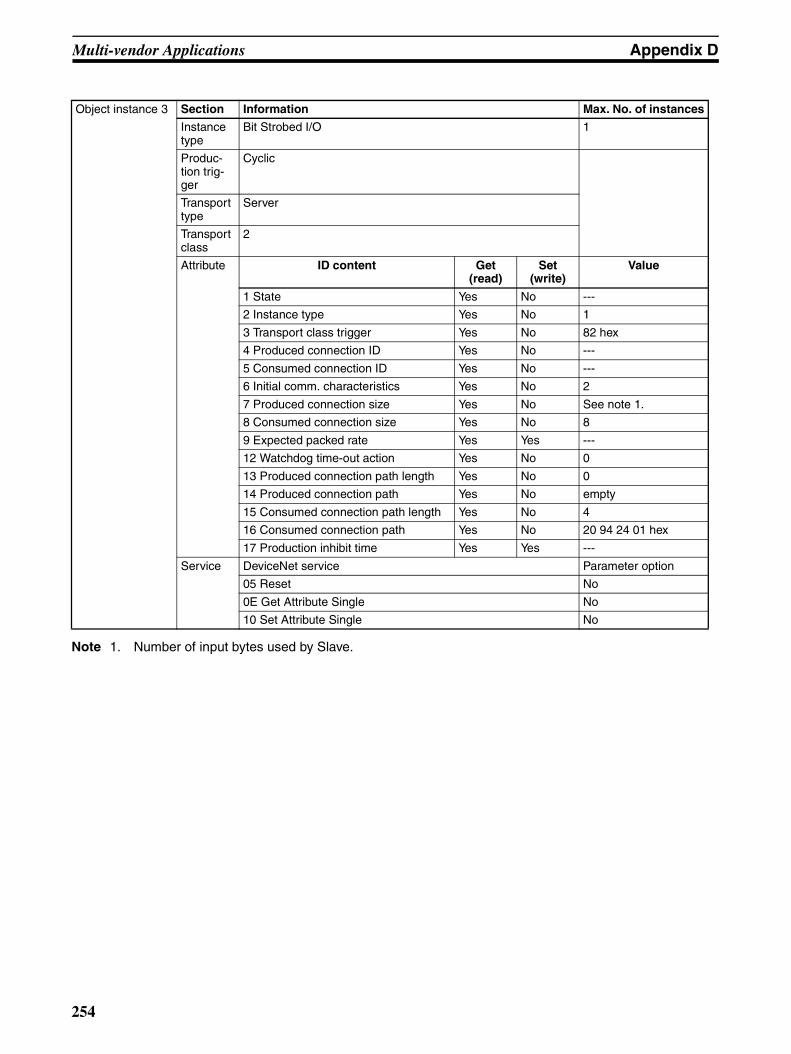
Multi-vendor Applications Appendix D
Note 1. Number of input bytes used by Slave.
Object instance 3 Section Information Max. No. of instances
Instance type
Bit Strobed I/O 1
Produc-tion trig-ger
Cyclic
Transport type
Server
Transport class
2
Attribute ID content Get (read)
Set (write)
Value
1 State Yes No ---
2 Instance type Yes No 1
3 Transport class trigger Yes No 82 hex
4 Produced connection ID Yes No ---
5 Consumed connection ID Yes No ---
6 Initial comm. characteristics Yes No 2
7 Produced connection size Yes No See note 1.
8 Consumed connection size Yes No 8
9 Expected packed rate Yes Yes ---
12 Watchdog time-out action Yes No 0
13 Produced connection path length Yes No 0
14 Produced connection path Yes No empty
15 Consumed connection path length Yes No 4
16 Consumed connection path Yes No 20 94 24 01 hex
17 Production inhibit time Yes Yes ---
Service DeviceNet service Parameter option
05 Reset No
0E Get Attribute Single No
10 Set Attribute Single No
254

Multi-vendor Applications Appendix D
Note 1. Number of input bytes used by Slave.
Object instance 4 Section Information Max. No. of instances
Instance type
COS/cyclic I/O 1
Produc-tion trig-ger
Cyclic
Transport type
Client
Transport class
0 (no ACK)/2 (with ACK)
Attribute ID content Get (read)
Set (write)
Value
1 State Yes No ---
2 Instance type Yes No 1
3 Transport class trigger Yes No 02 hex (with Cyclic ACK)12 hex (with COS ACK)00 hex (no Cyclic ACK)10 hex (no COS ACK)
4 Produced connection ID Yes No ---
5 Consumed connection ID Yes No FFFF hex (no ACK)
6 Initial comm. characteristics Yes No 01 hex (with ACK)0F hex (no ACK)
7 Produced connection size Yes No See note 1.
8 Consumed connection size Yes No ---
9 Expected packed rate Yes Yes ---
12 Watchdog time-out action Yes No 0
13 Produced connection path length Yes No 4
14 Produced connection path Yes No 20 94 24 01 hex
15 Consumed connection path length Yes No 0 (no ACK)4 (with ACK)
16 Consumed connection path Yes No empty (no ACK)20 2B 24 01 (with ACK)
17 Production inhibit time Yes Yes ---
Service DeviceNet service Parameter option
05 Reset No
0E Get Attribute Single No
10 Set Attribute Single No
255
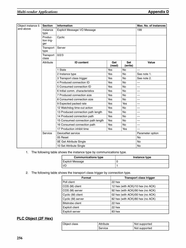
Multi-vendor Applications Appendix D
1. The following table shows the instance type by communications type.
2. The following table shows the transport class trigger by connection type.
PLC Object (2F Hex)
Object instance 5 and above
Section Information Max. No. of instances
Instance type
Explicit Message/ I/O Message 199
Produc-tion trig-ger
Cyclic
Transport type
Server
Transport class
0/2/3
Attribute ID content Get (read)
Set (write)
Value
1 State Yes No ---
2 Instance type Yes No See note 1.
3 Transport class trigger Yes No See note 2.
4 Produced connection ID Yes No ---
5 Consumed connection ID Yes No ---
6 Initial comm. characteristics Yes No ---
7 Produced connection size Yes No ---
8 Consumed connection size Yes No ---
9 Expected packed rate Yes Yes ---
12 Watchdog time-out action Yes No ---
13 Produced connection path length Yes No ---
14 Produced connection path Yes No ---
15 Consumed connection path length Yes No ---
16 Consumed connection path Yes No ---
17 Production inhibit time Yes Yes ---
Service DeviceNet service Parameter option
05 Reset No
0E Get Attribute Single No
10 Set Attribute Single No
Communications type Instance type
Explicit Message 0
I/O 1
Format Transport class trigger
Poll client 22 hex
COS (M) client 12 hex (with ACK)/10 hex (no ACK)
COS (M) server 92 hex (with ACK)/90 hex (no ACK)
Cyclic (M) client 02 hex (with ACK)/00 hex (no ACK)
Cyclic (M) server 82 hex (with ACK)/80 hex (no ACK)
Bitstrobe client 22 hex
Explicit client 22 hex
Explicit server 83 hex
Object class Attribute Not supported
Service Not supported
256
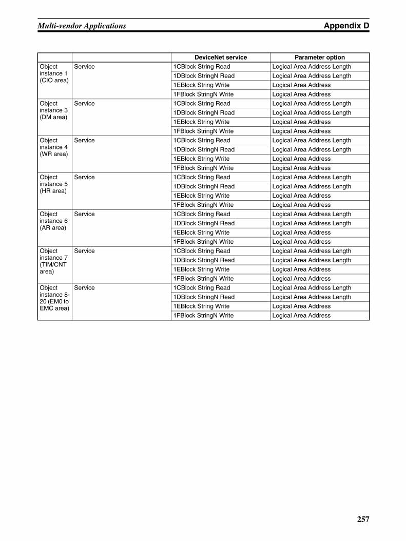
Multi-vendor Applications Appendix D
DeviceNet service Parameter option
Object instance 1 (CIO area)
Service 1CBlock String Read Logical Area Address Length
1DBlock StringN Read Logical Area Address Length
1EBlock String Write Logical Area Address
1FBlock StringN Write Logical Area Address
Object instance 3 (DM area)
Service 1CBlock String Read Logical Area Address Length
1DBlock StringN Read Logical Area Address Length
1EBlock String Write Logical Area Address
1FBlock StringN Write Logical Area Address
Object instance 4 (WR area)
Service 1CBlock String Read Logical Area Address Length
1DBlock StringN Read Logical Area Address Length
1EBlock String Write Logical Area Address
1FBlock StringN Write Logical Area Address
Object instance 5 (HR area)
Service 1CBlock String Read Logical Area Address Length
1DBlock StringN Read Logical Area Address Length
1EBlock String Write Logical Area Address
1FBlock StringN Write Logical Area Address
Object instance 6 (AR area)
Service 1CBlock String Read Logical Area Address Length
1DBlock StringN Read Logical Area Address Length
1EBlock String Write Logical Area Address
1FBlock StringN Write Logical Area Address
Object instance 7 (TIM/CNT area)
Service 1CBlock String Read Logical Area Address Length
1DBlock StringN Read Logical Area Address Length
1EBlock String Write Logical Area Address
1FBlock StringN Write Logical Area Address
Object instance 8-20 (EM0 to EMC area)
Service 1CBlock String Read Logical Area Address Length
1DBlock StringN Read Logical Area Address Length
1EBlock String Write Logical Area Address
1FBlock StringN Write Logical Area Address
257
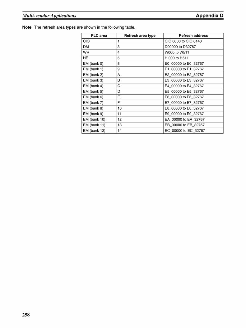
Multi-vendor Applications Appendix D
Note The refresh area types are shown in the following table.
PLC area Refresh area type Refresh address
CIO 1 CIO 0000 to CIO 6143
DM 3 D00000 to D32767
WR 4 W000 to W511
HE 5 H 000 to H511
EM (bank 0) 8 E0_00000 to E0_32767
EM (bank 1) 9 E1_00000 to E1_32767
EM (bank 2) A E2_00000 to E2_32767
EM (bank 3) B E3_00000 to E3_32767
EM (bank 4) C E4_00000 to E4_32767
EM (bank 5) D E5_00000 to E5_32767
EM (bank 6) E E6_00000 to E6_32767
EM (bank 7) F E7_00000 to E7_32767
EM (bank 8) 10 E8_00000 to E8_32767
EM (bank 9) 11 E9_00000 to E9_32767
EM (bank 10) 12 EA_00000 to EA_32767
EM (bank 11) 13 EB_00000 to EB_32767
EM (bank 12) 14 EC_00000 to EC_32767
258

Appendix EDeviceNet Explicit Message Send Command
for Other Manufacturer Nodes
Explicit Message Send (2801)Sends a DeviceNet explicit message to a specified object and receives aresponse.
Command Block
Response Block• When a normal response has been returned for the executed explicit
message:
• When an error response has been returned for the executed explicit mes-sage:
• When the explicit message execution failed or timed out:
Command Command code
Explicit message send 2801
534 bytes max.
Command code
Destination node address
Service codeClass ID Instance ID Service data
534 bytes max.
Command code
Source node address (local node)
Service code
No. of bytes received
Service dataEnd code
Command code
Source node address (local node)
Service code 94 (hex)
No. of bytes received
Error codeEnd code
Command code
End code
259

DeviceNet Explicit Message Send Command for Other Manufacturer Nodes Appendix E
Parameter Details[Send Destination Node Address] (Command)
Specifies the node address of the explicit message destination.The local node DeviceNet Unit is specified for CMND and IOWR instructioncontrol data for Explicit Message Send commands and the actual destinationnode is specified here.
[Service Code] (Command, response)For commands, the service code defined by the DeviceNet is specified.For normal responses, the value for when bit 15 of the service code specifiedin the command turns ON is returned. For error responses, 94 hex, which indi-cates an error, is returned.
[Class ID] (Command)Specifies the class ID for the explicit message destination.
[Instance ID] (Command)Specifies the instance ID for the explicit message destination.
[Service Data] (Command, response)For commands, specifies the data defined by the service code.For responses, returns the reception data defined by the service code.
[No. of Bytes Received] (Response)Returns the number of bytes received after Source (local node) NodeAddress.
[Source (local node) Node Address] (Response)Returns the local node DeviceNet node address that was the source of theexplicit message.
[Error Code] (Response)Returns the error code defined by the DeviceNet.
Explanation• The Explicit Message Send command sends a DeviceNet-defined explicit
message to an OMRON Special I/O Slave Unit or a Slave manufacturedby another company and receives a response.
• Unlike other FINS commands, the Explicit Message Send commandspecifies the local node DeviceNet Unit as the CMND and IOWR instruc-tion control code destination. The actual destination node is specifiedusing the Destination Node Address in the Explicit Message Send com-mand.Always specify the local node DeviceNet Unit in the CMND or IOWRinstruction control code. If another node Master unit is specified an errorwill occur.
• If the DeviceNet Master Unit receives an explicit message, it will automat-ically return a response.
Note 1. Refer to DeviceNet Specifications for explicit message parameter details.
2. For information on explicit messages for OMRON slave, refer to DeviceNet (CompoBus/D) SlaveManual (W347).
3. Contact the Open DeviceNet Vendor Association, Inc. (ODVA) at 8222 Wiles Road, Suite 287, CoralSprings, FL 33067 USA (phone: 954-340-5412, fax: 954-340-5413, e-mail: [email protected],Home page: http://www.odva.org/) to obtain copies of the specification.
260
Index
Aadaptors
remote, 4, 10allocations
See also I/O allocationsapplicable Units, 6applications
precautions, xviii
CC200HW-DRM21-V1
changing ladder programs, 79comparison, 30
cablesI/O Unit Connecting Cable, 15
CIO AreaSee also I/O allocations
cleaning, 227commands
delivering commands through a network, 150explicit message commands, 167FINS commands lists, 143, 243
communications, 23, 190, 191connection types, 127, 130, 237connectors, 51cycle time, 81, 190, 234
See also cycle timeerrors, 226flags, 151hardware preparation, 37high-speed, 21instructions, 8, 151
completion codes, 152message communications, 3, 8, 16, 27, 42, 133, 196
data area sizes, 152data send/receive instructions, 148errors, 139, 140explicit messages, 137
commandsBYTE DATA READ, 172BYTE DATA WRITE, 174CPU INFORMATION READ, 167CPU UNIT STATUS READ, 170CPU UNIT WRITE, 168WORD DATA READ, 173WORD DATA WRITE, 175
list of PLC object services, 165receiving, 164send command for other manufacturer nodes
EXPLICIT MESSAGE SEND (2801), 259sending, 157, 158sending using CMND(490), 160
FINS messages, 135, 141command lists, 143commands
ECHO BACK TEST (0801), 245ERROR HISTORY CLEAR (2103), 247READ CONTROLLER INFORMATION
(0501), 243READ CONTROLLER STATUS (0601),
244READ ERROR HISTORY (2102), 246RESET (0403), 243
connecting networks, 156sending/receiving, 142, 150Units supporting, 143
maximum message response time, 197monitoring timer, 140overview, 134programming examples, 153specifications, 138structure, 135time, 196timing for reading responses, 152using, 145
procedures prior to starting, 39remote I/O, 3, 16, 24
errors, 118, 224example ladder programming, 116restarting, 116See also Master UnitsSee also Slave Unitsspecifications, 123starting, 116stopping, 116
scan lists, 99software switches, 9status, 9time/Slave, 21, 27, 191timing, 189
ConfiguratorSee also DeviceNet Configurator
connections, 21, 237connection path, 239supported, 23, 27using allocations, 238
CPU Unitserrors, 215
indicators, 224I/O memory read/write, 166status read/write, 165
CX-Programmer, 19cycle time, 190
communications, 21, 190reference table, 87setup table, 81specifications, 27, 234
DDeviceNet Configurator, 16, 18, 28
connecting an OMRON slave to another company’s con-figurator, 249connections, 238functions, 34, 36making slave allocations, 94, 113, 130models, 34outline, 34saving files to Memory Card, 184
261
Index
specifications, 35dimensions, 55DM Area
See also I/O allocationsdot indicators
See also seven-segment display
EEC Directives, xxEEPROM
data, 27, 182errors, 203
codes, 221display, 48
communications, 226error flags, 71, 74, 76, 79error log functions, 220error log table, 220master, 204memory access, 212message communications, 139, 140network, 210remote I/O communications, 118scan lists, 226slave, 219software switch, 209Unit, 220
explicit message communicationsSee also communications
Ffeatures, 16
multi-vendor network, 16FINS communications
command codes, 243completion codes, 152connecting networks, 156See also communications
fixed allocationsSee also I/O allocations
flagsSee also communications
functions, 6, 28, 46DeviceNet Configurator, 4, 16master, 3, 6, 195Memory Card backup, 182slave, 4, 7, 17, 196
II/O allocations, 92
allocation size setup table, 84fixed, 39, 40, 101, 125
allocated words, 101, 125changing system components, 105CIO Area, 93connections, 238example, 105
procedure, 102, 125using remote I/O master, 97using remote I/O slave, 123
methods, 122user-set, 17, 82, 85, 107, 126
connection types, 127, 130connections using, 238master user-set allocations reference table, 87methods, 93, 107, 126procedure, 39, 41, 127setting through allocated DM area words, 108, 127setting through Configurator, 113, 130slave user-set allocations reference table, 88using remote I/O master, 97, 98using remote I/O slave, 124
word allocations, 23CIO Area, 59, 60
C200 master replacement master status 1 (wordn+24), 79
disconnect/connect switches (words n+6 to n+9),69
master COS send switches (words n+2 to n+5),69, 240
master status 1 (word n+12), 74master status 2 (word n+13), 75normal slave table (words n+20 to n+23), 79registered slave table (words n+16 to n+19), 78slave status 1 (word n+14), 76slave status 2 (word n+15), 78software switches 1 (word n), 60software switches 2 (word n+1), 65unit status 1 (word n+10), 71unit status 2 (word n+11), 72
DM Area, 59, 81allocation size setup table, 84communications cycle time reference table, 87communications cycle time setup table, 81master user allocations setup table, 82master user-set allocations reference table, 87slave detailed status, 89slave user allocations setup table, 85slave user-set allocations reference table, 88
overview, 58I/O Link Units, 4
C200H I/O Link Unit, 5, 12CQM 1 I/O Link Unit, 11errors, 225
I/O memoryread/write for CPU Units, 166
I/O response timesmaximum, 193minimum, 194
CS1-series and C200HX/HG/HE/HS PCs, 194I/O Terminals, 4
environment-resistant, 4, 12water-resistant, 12
I/O Unitsconnecting cable, 15See also Master UnitsSee also Slave Units
indicators
262
Index
display section, 29Master Unit, 202meaning, 47message communications errors, 139seven-segment display, 48status
MS and NS, 47troubleshooting, 202, 224
inspection, 227installation, 51instructions
CMND(490), 150, 151RECV(098), 149, 151SEND(090), 148, 151
Lladder programs
replacing, 235
Mmaintenance, 227
cleaning, 227inspection, 227
Master Units, 6, 9connecting another company’s slave to an OMRON mas-ter, 249device profile, 250errors, 204I/O allocations, 82
See also I/O allocationsindicators, 202multiple, 20, 195node address display, 48number of, 96precautions, 96remote I/O
communications, 92procedures, 97specifications, 25, 95
status, 202status areas, 232system startup time, 195user-set allocations reference table, 87using master function, 39
memory accesserrors, 212
Memory Card, 20, 28, 182message communications
See also communicationsmessage monitoring timer, 140message response time, 197mounting, 52
objects, 250MULTIPLE I/O TERMINAL Units, 5, 14multi-vendor environment, 249multi-vendor network
See also features
Nnetworks
connecting for FINS communications, 156errors, 210installation procedure, 37inter-network connections, 19multiple masters, 195multiple PCs on a single network, 20
Oobjects, 250
Connection Object, 251DeviceNet Object, 251Identity Object, 250Message Router Object, 250PC Object, 256See also PLC object services
operationbasic operation procedures, 37operating environment
precautions, xviioperating status
Master Unit, 202overview, 2
PPLC object services, 165precautions, xv
applications, xviiigeneral, xvihandling, 53Master Units
number of, 96operating environment, xviisafety, xvisystem configuration, 51
previous modelscomparison, 30replacing ladder programs, 235
programmingexamples, 153See also instructionsSee also ladder programs
Rrefresh time, 192remote I/O
communications characteristics, 190See also communications
replacement, 228replacing ladder programs, 235See also setup
routing tables, 146local network tables, 146relay network tables, 147
RS-232C Units, 5, 12
263

Index
Ssafety precautions, xviscan lists, 99
errors, 226setup
saving setup files, 20, 182seven-segment display
meaning, 48Slave Units, 7, 9, 21
communications time, 191connecting an OMRON slave to another company’s con-figurator, 249connecting another company’s slave to an OMRON mas-ter, 249environment-resistant, 12errors, 219faulty node address display, 48general-purpose, 10I/O allocations, 85
See also I/O allocationsmonitoring, 19multiple, 20programmable, 12programming, 19remote I/O
communications, 122procedures, 123specifications, 26, 123
See also adaptorsSee also I/O Link UnitsSee also I/O TerminalsSee also MULTIPLE I/O TERMINAL UnitsSee also RS-232C UnitsSee also terminalsspecial, 12status, 89system startup time, 196user-set allocations reference table, 88using slave function, 40water-resistant, 12
specificationsdefault settings, 27general, 22network length, 21other functions, 28remote I/O, 25, 26, 95
startup procedurescommunications, 39
startup times, 195status
areascomparison with previous models, 232
indicators, 47Master Unit, 202read/write for CPU Units, 165
switches, 28, 46procedures prior to starting communications, 39settings, 49
errors, 226
software switchescomparison with previous models, 231See also I/O allocationssetting errors, 209
systemconfiguration, 3startup times, 195
Ttables
error log, 220local network, 146normal slave, 235registered slave, 234relay network, 147routing, 146
terminalsanalog input, 4, 11analog output, 4, 11B7AC Interface Terminal, 12remote I/O, 10See also I/O Terminalssensor, 4, 11temperature input, 5, 11
timermessage monitoring, 140
timingcommunications, 189reading responses, 152
troubleshooting, 201, 224
UUnits
applicable, 7usage, 43user-set allocations
See also I/O allocations
VVME Master Boards, 3
Wwaterproof, 12word allocations
See also I/O allocations
264
265
Revision History
A manual revision code appears as a suffix to the catalog number on the front cover of the manual.
The following table outlines the changes made to the manual during each revision. Page numbers refer to theprevious version.
Revision code Date Revised content
1 October 2000 Original production
2 July 2001 Major revisions to add the CJ-series DeviceNet Unit. “CS1” was changed to “CS” or “CS/CJ” as appropriate and the fol-lowing changes were made. Other changes are as follows:Page ix: Manual contents updated and manuals added to table.Page xiv: Precaution added on providing double safety mechanisms.Page xv: EMC standards updated.Page xvi: Impedances, manufacturer, and dimensions changed.Page 2: Changed to “DeviceNet Unit” to clarify meaning.Page 3: Corrected callout at upper right of page.Pages 8 and 25: Number of node for FINS communications changed.Pages 8, 16, 17, 18, 19: Notes added. Pages 10, 11, 15: Products added.Page 15: OS updated in table.Page 16: Graphics changed.Page 17: Bottom graphic and description changed.Page 31: Routing table item added to table.Page 33: Maximum words per slave item added to table.Page 34: Corrected CIO 3770 number.Page 36, 37: Added PCI Board info to graphic and tables.Page 39: Note added.Page 41: Routing table section added.Pages 42, 43, 44: Slight change in procedure.Page 48: Graphic added.Pages 48, 49, 50: Information added from previous sections 8-2, 8-3, and graphics changed.Page 51: Graphics changed.Page 52: Note added, graphic added.Page 55: CJ-series explanation added.Page 56: Graphic added.Page 60: Information added to Software Switches 1 description.Pages 62, 63, 64, 65: Table items added.Page 95: Address numbers changed in graphic.Page 101: Note in item 7 corrected (Right changed to Left).Page 101: Same note in item 6 corrected (Right changed to Left).Page 102: Note 2 added concerning Configurator Ver. 2.10.Page 105: Change made to Step 2 of 4-3-2, and Step 3 added.Page 107: Table changed.Page 109: Allocation tables changed.Page 114: Changes made to Changing System Components section.Page 118: Note added concerning Configurator Ver. 2.10.Page 119: Changes made to 4-5-1.Page 119: Changes made to 4-5-2.Page 120: Note added.Page 127: Note 2 added concerning Configurator Ver. 2.10.Page 133: Note 2 added concerning Configurator Ver. 2.10.Page 140: Explanation of node address 0 added to table.Page 142: Revision made to note in section 6-1-6.Pages 146, 147, 148, 149: Sections 6-3 to 6-3-2 newly added.Pages 157, 158: Section 6-4 moved from previous location in section 6-6.Page 160: Note content changed.Page 174: Reference to manual changed in Note.Pages 181, 182, 183, 184, 185: Sections 7-1 to 7-1-4 newly added.Pages 185, 186, 187: Sections 7-2 to 7-2-2 moved from Appendix.Page 193: PC cycle time delay calculation in two Notes changed from 0.25 ms + 1.5 ms to 0.7 ms.Page 194: Table item changed from (TPC-TRF) to (TPC+TRF).Page 197: PC cycle time delay calculation changed from 0.25 ms + 1.5 ms to 0.7 ms.Page 200: Information from previous sections 8-2, 8-3 moved to pages 48, 49, 50.Page 222: Reference to Slaves Operation Manual changed.Page 225: Reference to Slaves Operation Manual changed.Page 225: DNnnBKUP.DAT changed to DNnnBKUP.dvf in Note 3.Page 232: Note added.
03 January 2003 “PLC” was changed to “PC,” where appropriate, throughout the manual.Page v: Changes made to text under “OMRON Product References.”Page xvi: Text removed from table.Page 4: Line added after “Analog Input Terminals.” Minor change made to text under “Analog Output Terminals.”Page 10: Heading added.Page 12: Tables added.Page 31: Minor change made to text in sixth box from top of rightmost column.Page 106: Changes made to diagram in several places.Page 143: Four commands removed from bottom table.Page 144: One command added and one command removed from table.Page 159: Unit name corrected in one place in first diagram.Pages 168, 169, 170, 171, 172, 174, 175, 176, 177, 178, 179: Block formats changed.Pages 168, 172, 174, 176, 177, 178: Notes added.Pages 168, 170, 172, 175, 176, 177, 178, 179: Information on destination node address removed.Pages 168, 172, 177, 178, 179: Information on the number of bytes received removed.Pages 168, 170, 172, 175, 176, 177, 179: Minor numerical changes made to Class ID.Pages 168, 170, 172: Minor numerical changes made to Instance ID.Page 171: Text under block format removed.Pages 175, 176, 178, 179: Minor change made to information on Instance ID.Page 252: Manufacturer revision changed in first table. Product code and revision number changed in third table.
Cat. No. W380-E1-05
Revision code
04 September 2003 “(-V1)” was added to the CS1W-DRM21 model number throughout the manual.Page ix: Note added. Page x: Information corrected in table. Pages 21, 28, 184, and 210: Information on simple backup function added. Page 29: Information on CS1W-DRM2-V1 added and model number corrected.Page 31: Information in fourth row from the bottom in rightmost column cor-rected.Page 38: Manual name corrected and catalog number added. Page 46: “For this Unit” added in two places.Page 126: Total allocation size corrected for Configurator setting. Page 187: Information added and term changed. Page 222: Manual reference added. Page 231: Information added to table.Page 232: Graphic changed.Page 234: Note changed. Pages 243 to 245: Appendix deleted.
05 July 2005 Page v: Information on general precautions notation added.Page x: Information on liability and warranty added.
Revision code Date Revised content
266

OMRON CorporationControl Devices Division H.Q.Shiokoji Horikawa, Shimogyo-ku,Kyoto, 600-8530 JapanTel: (81)75-344-7109/Fax: (81)75-344-7149
Regional Headquarters
OMRON EUROPE B.V.Wegalaan 67-69, NL-2132 JD HoofddorpThe NetherlandsTel: (31)2356-81-300/Fax: (31)2356-81-388
OMRON ELECTRONICS LLC1 East Commerce Drive, Schaumburg, IL 60173U.S.A.Tel: (1)847-843-7900/Fax: (1)847-843-8568
OMRON ASIA PACIFIC PTE. LTD.83 Clemenceau Avenue, #11-01, UE Square,Singapore 239920Tel: (65)6835-3011/Fax: (65)6835-2711
OMRON (CHINA) CO., LTD.Room 2211, Bank of China Tower, 200 Yin Cheng Zhong Road,PuDong New Area, Shanghai, 200120 ChinaTel: (86)21-5037-2222/Fax: (86)21-5037-2200

Authorized Distributor:
Cat. No. W380-E1-05 Note: Specifications subject to change without notice. Printed in Japan
This manual is printed on 100% recycled paper.