
Synthesizable Coding of of Verilog -...
71
ACCESS IC LAB Graduate Institute of Electronics Engineering, NTU Synthesizable Coding of Synthesizable Coding of Verilog Verilog Lecturer: Chihhao Chao Date: 2009.03.18
Transcript of Synthesizable Coding of of Verilog -...

ACCESS IC LAB
Graduate Institute of Electronics Engineering, NTU
Synthesizable Coding of Synthesizable Coding of VerilogVerilog
Lecturer: Chihhao ChaoDate: 2009.03.18

Graduate Institute of Electronics Engineering, NTU
pp. 2Synthesizable Coding of Verilog - 2009.3.18
OutlineOutlinevBasic concepts of logic synthesisvSynthesizable Verilog coding subsetvVerilog coding practicesvCoding for readabilityvCoding for synthesisvPartitioning for synthesis
Chihhao Chao

Graduate Institute of Electronics Engineering, NTU
pp. 3Synthesizable Coding of Verilog - 2009.3.18
OutlineOutlinevBasic concepts of logic synthesisvSynthesizable Verilog coding subsetvVerilog coding practicesvCoding for readabilityvCoding for synthesisvPartitioning for synthesis
Chihhao Chao
Graduate Institute of Electronics Engineering, NTU
pp. 4Synthesizable Coding of Verilog - 2009.3.18
What is logic synthesisWhat is logic synthesisv Logic synthesis is the process of converting a high-
level description of design into an optimized gate-level representation.
v Logic synthesis uses standard cell library which have simple cells, such as basic logic gates like and, or, and nor, or macro cells, such as adder, multiplexers, memory, and special flip-flops.
v Use Design Compiler to synthesize the circuit in order to meet design constraints such as timing, area, testability, and power.
Chihhao Chao

Graduate Institute of Electronics Engineering, NTU
pp. 5Synthesizable Coding of Verilog - 2009.3.18
What is logic synthesisWhat is logic synthesisvSynthesis = translation + optimization + mapping
residue = 16’h0000;if ( high_bits == 2’b10)residue = state_table[index];
else state_table[index] =16’h0000;
HDL Source(RTL)
Generic Boolean(GTECH)
Translate (HDL Compiler)
no timing info.
Target Technology
Optimize + Map(Design Compiler)
timing info.
Chihhao Chao

Graduate Institute of Electronics Engineering, NTU
pp. 6Synthesizable Coding of Verilog - 2009.3.18
Synthesis is Constraint DrivenSynthesis is Constraint Driven
always @(reset or set)begin : direct_set_resetif (reset)
y=1'b0;else if (set)
y=1'b1;endalways @(gate or reset)if (reset)
t=1'b0;else if (gate)
t=d;
Translation
optimization
Speed
Area
SlowFast
Small
Large
Chihhao Chao

Graduate Institute of Electronics Engineering, NTU
pp. 7Synthesizable Coding of Verilog - 2009.3.18
Technology IndependentTechnology Independentv Through synthesis, design can be translated to any
technology.
Speed
Area
Technology A
Technology B
SlowFast
Small
Large
Chihhao Chao

Graduate Institute of Electronics Engineering, NTU
pp. 8Synthesizable Coding of Verilog - 2009.3.18
Limitation on Manual DesignLimitation on Manual Designv Error-Prone: for large designs, manual conversion was prone
human error, such as a small gate missed somewhere
v Hard to Verify: the designer could never be sure that the design constraints were going to be met until the gate-level implementation is complete and tested
v Time-Consuming: A significant portion of the design cycle was dominated by the time taken to convert a high-level design into gates
v Hard to reuse: design reuse was not possible
v Impossible to optimize globally: Each designer would implement design blocks differently. For large designs, this could mean that smaller blocks were optimized but the overall design was not optimal
Chihhao Chao

Graduate Institute of Electronics Engineering, NTU
pp. 9Synthesizable Coding of Verilog - 2009.3.18
Impact of Logic SynthesisImpact of Logic Synthesisv Automated Logic synthesis tools addressed these
problems as followsv Fewer human error, because designs are described at a higher
level of abstraction
v High-level design is done without significant concern about design constraints.
v Conversion from high-level design to gates is fast
v Logic synthesis tools can optimize the design globally.
v Logic synthesis tools allow technology-independent design
v Design reuse is possible ( reuse the higher-level description )
Chihhao Chao

Graduate Institute of Electronics Engineering, NTU
pp. 10Synthesizable Coding of Verilog - 2009.3.18
Logic SynthesisLogic Synthesisv Takes place in two stages:
1. Translation of Verilog (or VHDL) source to a netlistv Performs architectural optimizations and then creates an
internal representation of the design.v Usually this is automatically done while design is imported to
the synthesis tool.
2. Optimization of the resulting netlist to fit constraints on speed (timing constraint) and area (area constraint)v Most critical part of the processv Logic optimization + Gate optimization
Chihhao Chao

Graduate Institute of Electronics Engineering, NTU
pp. 11Synthesizable Coding of Verilog - 2009.3.18
Translating Verilog into GatesTranslating Verilog into GatesvParts of the language easy to translatevStructural descriptions with primitive gatesØAlready a netlist
vContinuous assignmentØExpressions turn into little datapaths
vBehavioral statements vSynthesizable coding subset
Chihhao Chao

Graduate Institute of Electronics Engineering, NTU
pp. 12Synthesizable Coding of Verilog - 2009.3.18
Optimization: the “Art” of SynthesisOptimization: the “Art” of Synthesisvcompile command drives synthesis tool to
optimize the design
Compile
Synopsystechnology
library
Optimized Design
Schematic
ReportsAttributes and
constraints
RTL code or netlist
Chihhao Chao

Graduate Institute of Electronics Engineering, NTU
pp. 13Synthesizable Coding of Verilog - 2009.3.18
CompileCompile
Technology independent
Technology dependent
Chihhao Chao

Graduate Institute of Electronics Engineering, NTU
pp. 14Synthesizable Coding of Verilog - 2009.3.18
Logic Level OptimizationLogic Level OptimizationvOperate with Boolean representation of a
circuitvHas a global effect on the overall area/speed
characteristic of a designvStrategyvStructurevFlattenvIf both are true, the design is first flattened and
then structured
Chihhao Chao
Graduate Institute of Electronics Engineering, NTU
pp. 15Synthesizable Coding of Verilog - 2009.3.18
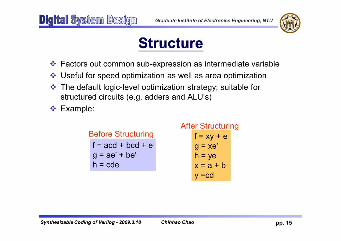
StructureStructurev Factors out common sub-expression as intermediate variablev Useful for speed optimization as well as area optimizationv The default logic-level optimization strategy; suitable for
structured circuits (e.g. adders and ALU’s)v Example:
f = acd + bcd + eg = ae’ + be’h = cde
f = xy + eg = xe’h = yex = a + by =cd
Before StructuringAfter Structuring
Chihhao Chao
Graduate Institute of Electronics Engineering, NTU
pp. 16Synthesizable Coding of Verilog - 2009.3.18
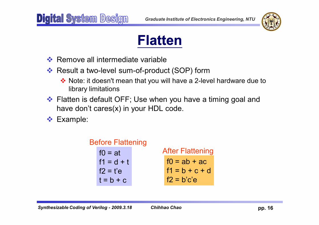
FlattenFlattenv Remove all intermediate variablev Result a two-level sum-of-product (SOP) form
v Note: it doesn't mean that you will have a 2-level hardware due to library limitations
v Flatten is default OFF; Use when you have a timing goal and have don’t cares(x) in your HDL code.
v Example:
f0 = atf1 = d + tf2 = t’et = b + c
f0 = ab + acf1 = b + c + df2 = b’c’e
Before FlatteningAfter Flattening
Chihhao Chao

Graduate Institute of Electronics Engineering, NTU
pp. 17Synthesizable Coding of Verilog - 2009.3.18
Gate Level OptimizationGate Level OptimizationvSelect components to meet timing, design
rule & area goals specified for the circuitvHas a local effect on the area/speed
characteristics of a designvStrategyvMappingØCombinational mappingØSequential mapping
Chihhao Chao
Graduate Institute of Electronics Engineering, NTU
pp. 18Synthesizable Coding of Verilog - 2009.3.18
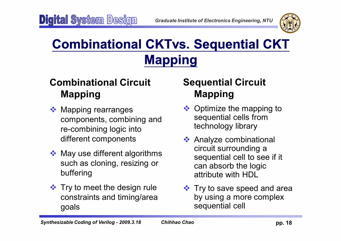
Combinational Combinational CKTvsCKTvs. Sequential CKT . Sequential CKT MappingMapping
Combinational Circuit Mapping
v Mapping rearranges components, combining and re-combining logic into different components
v May use different algorithms such as cloning, resizing or buffering
v Try to meet the design rule constraints and timing/area goals
Sequential Circuit Mapping
v Optimize the mapping to sequential cells from technology library
v Analyze combinational circuit surrounding a sequential cell to see if it can absorb the logic attribute with HDL
v Try to save speed and area by using a more complex sequential cell
Chihhao Chao

Graduate Institute of Electronics Engineering, NTU
pp. 19Synthesizable Coding of Verilog - 2009.3.18
MappingMappingCombinational mapping Sequential mapping
Assume c loading high
Assume g loading high
Chihhao Chao
Graduate Institute of Electronics Engineering, NTU
pp. 20Synthesizable Coding of Verilog - 2009.3.18
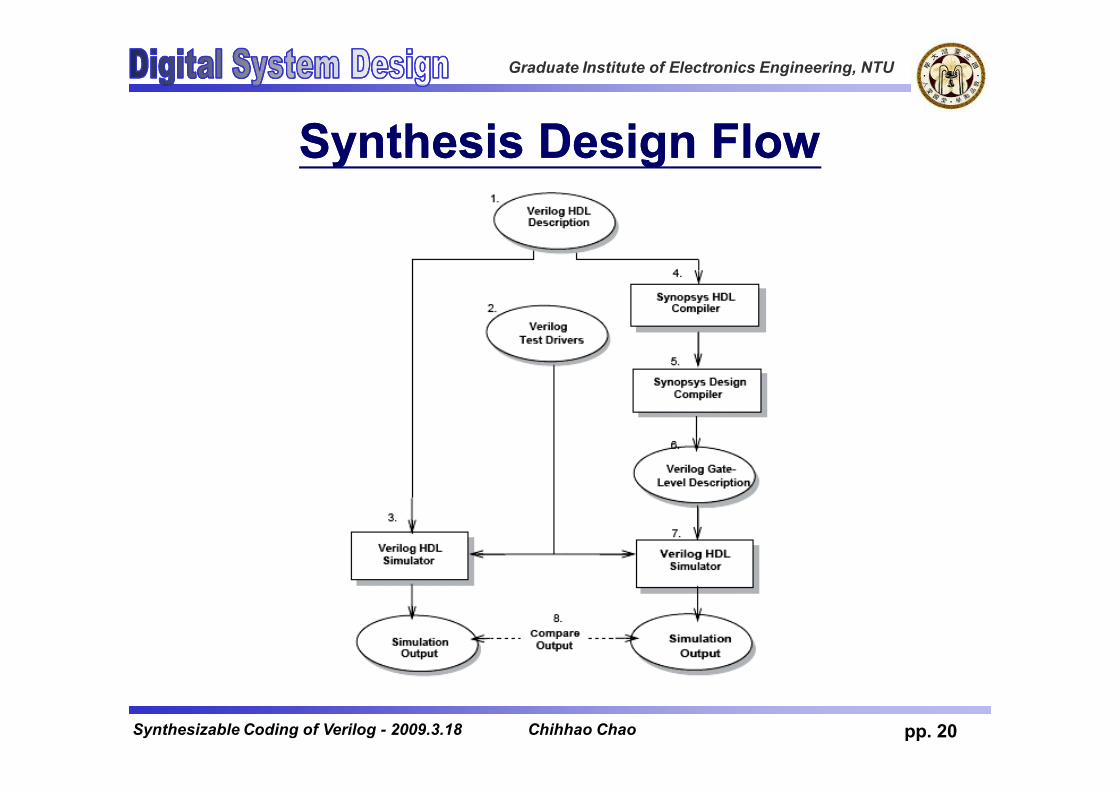
Synthesis Design FlowSynthesis Design Flow
Chihhao Chao

Graduate Institute of Electronics Engineering, NTU
pp. 21Synthesizable Coding of Verilog - 2009.3.18
OutlineOutlinevBasic concepts of logic synthesisvSynthesizable Verilog coding subsetvVerilog coding practicesvCoding for readabilityvCoding for synthesisvPartitioning for synthesis
Chihhao Chao

Graduate Institute of Electronics Engineering, NTU
pp. 22Synthesizable Coding of Verilog - 2009.3.18
Synthesizable Verilog CodeSynthesizable Verilog CodevNot all kinds of Verilog constructs can be
synthesized.vOnly a subset of Verilog constructs can be
synthesized and the code containing only this subset is synthesizable.
Chihhao Chao

Graduate Institute of Electronics Engineering, NTU
pp. 23Synthesizable Coding of Verilog - 2009.3.18
HDL Compiler UnsupportedHDL Compiler Unsupportedv delayv initialv repeatv waitv fork … joinv eventv deassignv forcev releasev primitive -- User defined
primitive v time
v triand, trior, tri1, tri0, triregv nmos, pmos, cmos, rnmos,
rpmos, rcmosv pullup, pulldownv rtran, tranif0, tranif1, rtranif0,
rtranif1v case identity and not identity
operatorsv Division and modulus
operatorsv division can be done using
DesignWare instantiation
Chihhao Chao

Graduate Institute of Electronics Engineering, NTU
pp. 24Synthesizable Coding of Verilog - 2009.3.18
Verilog Basis & Primitive Cell SupportedVerilog Basis & Primitive Cell Supportedv Verilog basisv Parameter declarationsvWire, wand, wor declarationsv Reg declarationsv Input, output, inout declarationsv Continuous assignmentsvModule instantiationsv Gate instantiationsv Always blocksv Task statementsv Function definitionsv For, while loop
v Synthesizable Verilog primitive cellsv And, or, not, nand, nor, xor, xnorv Bufif0, bufif1, notif0, notif1
Chihhao Chao
Graduate Institute of Electronics Engineering, NTU
pp. 25Synthesizable Coding of Verilog - 2009.3.18
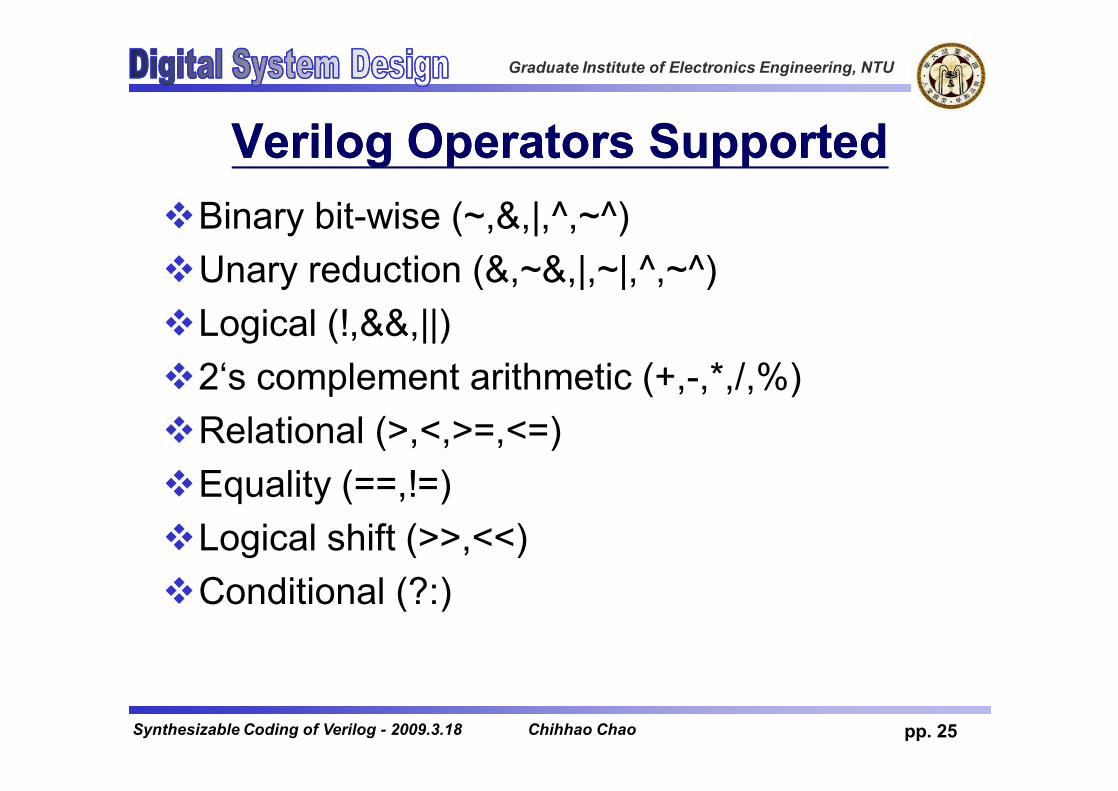
Verilog Operators SupportedVerilog Operators SupportedvBinary bit-wise (~,&,|,^,~^)vUnary reduction (&,~&,|,~|,^,~^)vLogical (!,&&,||)v2‘s complement arithmetic (+,-,*,/,%)vRelational (>,<,>=,<=)vEquality (==,!=)vLogical shift (>>,<<)vConditional (?:)
Chihhao Chao

Graduate Institute of Electronics Engineering, NTU
pp. 26Synthesizable Coding of Verilog - 2009.3.18
Comparisons to X or ZComparisons to X or Zv A comparison to an X or Z is always evaluated to
false.vmay cause simulation & synthesis mismatch.
module compare_x(A,B);input A;output B;reg B;always beginif (A== 1'bx)B=0;
elseB=1;
endendmodule
Warning: Comparisons to a “don’t care”are treated as always being false in routinecompare_x line 7 in file “compare_x.v”this may cause simulation to disagree withsynthesis. (HDL-170)
Chihhao Chao
Graduate Institute of Electronics Engineering, NTU
pp. 27Synthesizable Coding of Verilog - 2009.3.18
OutlineOutlinevBasic concepts of logic synthesisvSynthesizable Verilog coding subsetvVerilog coding practicesvCoding for readabilityvCoding for synthesisvPartitioning for synthesis
Chihhao Chao

Graduate Institute of Electronics Engineering, NTU
pp. 28Synthesizable Coding of Verilog - 2009.3.18
PrePre--RTL Preparation ChecklistRTL Preparation ChecklistvCommunicate design issues with your teamvNaming conventions, revision control, directory
trees and other design organizationsvHave a specification for your designvEveryone should have a specification BEFORE
they start codingvDesign partitionvFollow the specification’s recommendations for
partitionvBreak the design into major functional blocks
Chihhao Chao

Graduate Institute of Electronics Engineering, NTU
pp. 29Synthesizable Coding of Verilog - 2009.3.18
RTL Coding StyleRTL Coding StylevCreate a block level drawing of your design
before you begin coding.vDraw a block diagram of the functions and sub-
functions of your design.vAlways think of the poor guy who has to read
your RTL code.vCorrelate “top to bottom” in the RTL description
with ”left to right” in the block diagram.vComments and headers.
vHierarchy design
Chihhao Chao

Graduate Institute of Electronics Engineering, NTU
pp. 30Synthesizable Coding of Verilog - 2009.3.18
General Naming Conventions(1/3)General Naming Conventions(1/3)v Use lowercase letters for all signal names, variable
names, and port names.v Use uppercase letters for names of constants and user-
defined types.v User meaningful names for signals, ports, functions, and
parametersv Do not use ra for a RAM address bus, use ram_addr
v Use the same name or similar names for ports and signals that are connected
v Use short but descriptive names for parametersv Avoid excessively long names during elaboration
Chihhao Chao

Graduate Institute of Electronics Engineering, NTU
pp. 31Synthesizable Coding of Verilog - 2009.3.18
General Naming Conventions(2/3)General Naming Conventions(2/3)v Use clk for the clock signalv If there is more than one clock, use clk as the prefix for all
clock signals (clk1, clk2, clk_interface)
v Use the same name for all clock signals that are driven from the same source
v For active low signals, end the signal name with an underscore followed by a lowercase character (e.g. _n).v Use the same lowercase character consistently to indicate
active-low signals throughout the design
v Use rst for the reset signal. If the reset signal is active low, use rst_n
Chihhao Chao

Graduate Institute of Electronics Engineering, NTU
pp. 32Synthesizable Coding of Verilog - 2009.3.18
General Naming Conventions(3/3)General Naming Conventions(3/3)vUse [x:0] when describing multibit busesvA somewhat arbitrary suggested “standard” by the
AuthorvUse a distinctive suffix for state variable
names.v<name>_cs for the current statev<name>_ns for the next state
Chihhao Chao

Graduate Institute of Electronics Engineering, NTU
pp. 33Synthesizable Coding of Verilog - 2009.3.18
Signal Naming ConventionsSignal Naming Conventions
Convention Use*_r Output of a register*_a Asynchronous signal*_pn Signal used in the nth phase*_nxt Data before being registered
into a register with the same name
*_z Tristate internal signal
Chihhao Chao
Graduate Institute of Electronics Engineering, NTU
pp. 34Synthesizable Coding of Verilog - 2009.3.18
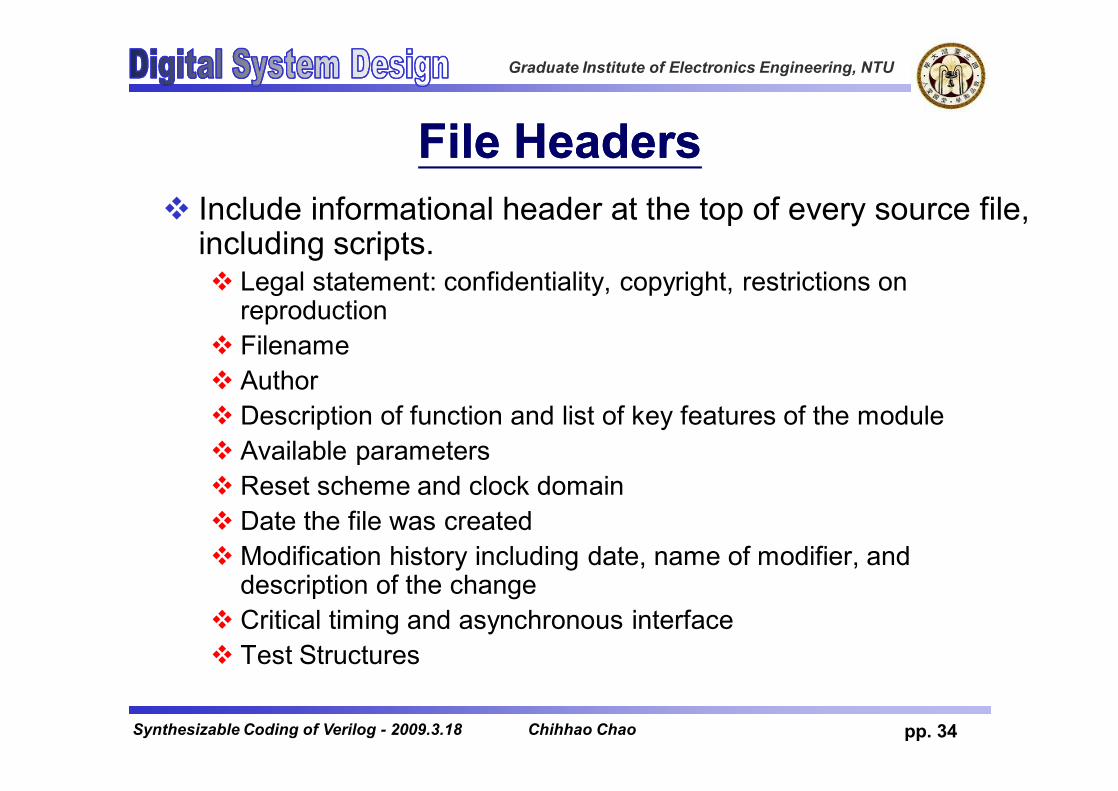
File HeadersFile Headersv Include informational header at the top of every source file,
including scripts.v Legal statement: confidentiality, copyright, restrictions on
reproductionv Filenamev Authorv Description of function and list of key features of the modulev Available parametersv Reset scheme and clock domainv Date the file was createdvModification history including date, name of modifier, and
description of the changev Critical timing and asynchronous interfacev Test Structures
Chihhao Chao

Graduate Institute of Electronics Engineering, NTU
pp. 35Synthesizable Coding of Verilog - 2009.3.18
File Header Example: ALU.v (1/2)File Header Example: ALU.v (1/2)
Chihhao Chao

Graduate Institute of Electronics Engineering, NTU
pp. 36Synthesizable Coding of Verilog - 2009.3.18
File Header Example: ALU.v (2/2)File Header Example: ALU.v (2/2)
Chihhao Chao
Graduate Institute of Electronics Engineering, NTU
pp. 37Synthesizable Coding of Verilog - 2009.3.18
Use commentsUse commentsvUse comments appropriately to explain
blocks, functions, ports, signals, and variables, or groups of signals or variables.vLogically, near the code that they describevBrief, concise, explanatoryvAvoid “comment clutter”– obvious functionality
does not need to be commentedvDescribe the intent behind the section of code
Chihhao Chao

Graduate Institute of Electronics Engineering, NTU
pp. 38Synthesizable Coding of Verilog - 2009.3.18
More on ReadabilityMore on ReadabilityvUse a separate line for each HDL statementvKeep the line length to 72 characters or lessvUse indentation to improve the readability of
continued code lines and nested loopsvUse indentation of 2 spaces, avoid large
indentationvAvoid using tabs
vDo not use Verilog reserved words for names of any elements
Chihhao Chao

Graduate Institute of Electronics Engineering, NTU
pp. 39Synthesizable Coding of Verilog - 2009.3.18
PortsPortsvDeclare one port per line, with a comment
following it on the same linevUse comments to describe groups of portsvDeclare the ports in the following order, first
input then output ports:vInputsØClocksØResetsØEnablesØOther control signalsØData and address
lines
vOutputsØClocksØResetsØEnablesØOther control signalsØdata
Chihhao Chao

Graduate Institute of Electronics Engineering, NTU
pp. 40Synthesizable Coding of Verilog - 2009.3.18
Port MappingPort MappingvAlways use explicit mapping for ports, use
named association rather than positional association
Chihhao Chao
Graduate Institute of Electronics Engineering, NTU
pp. 41Synthesizable Coding of Verilog - 2009.3.18
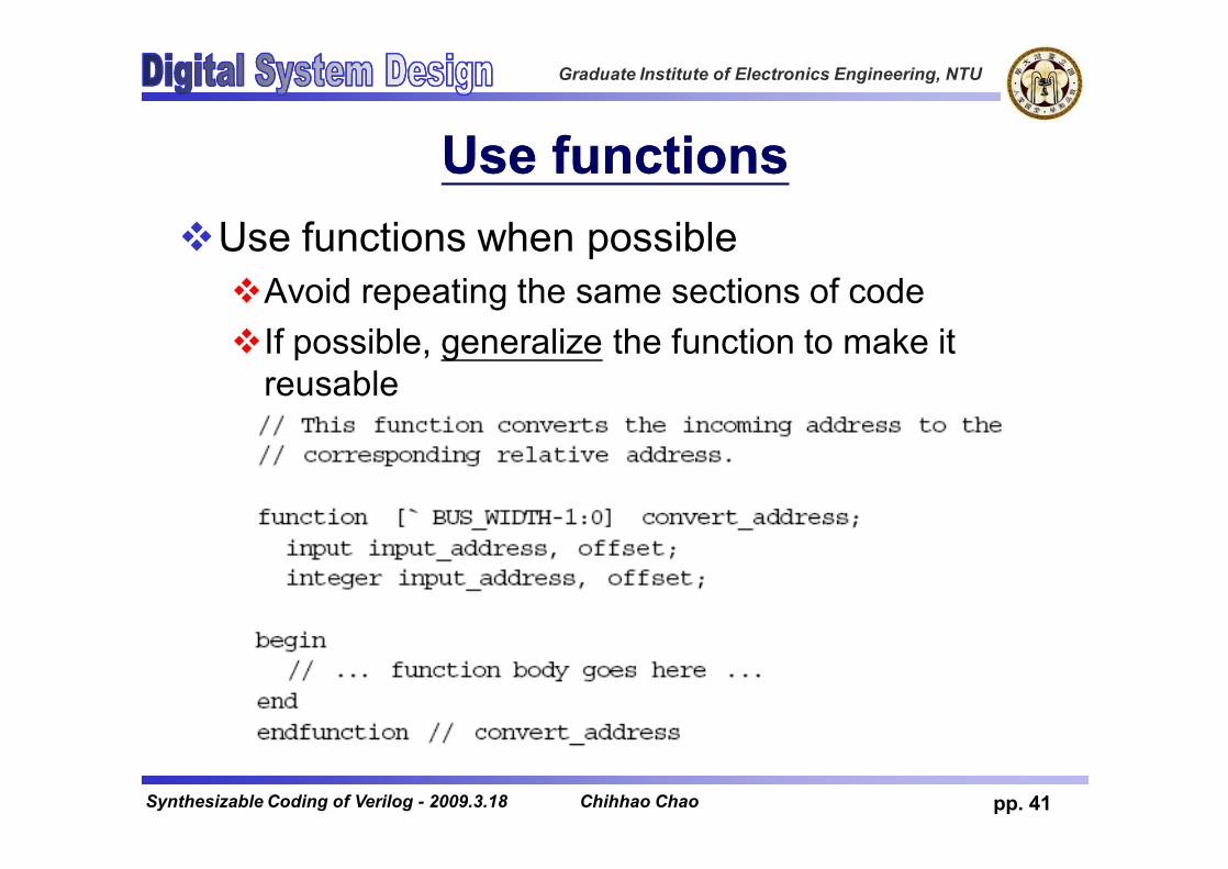
Use functionsUse functionsvUse functions when possiblevAvoid repeating the same sections of codevIf possible, generalize the function to make it
reusable
Chihhao Chao

Graduate Institute of Electronics Engineering, NTU
pp. 42Synthesizable Coding of Verilog - 2009.3.18
Do Not Use HardDo Not Use Hard--Coded Numeric Coded Numeric ValuesValues
v Constants associate a design intention with the value.v Constant values can be changed in one place.v Compilers can spot typos in constants but not in
hard-coded values.
Chihhao Chao

Graduate Institute of Electronics Engineering, NTU
pp. 43Synthesizable Coding of Verilog - 2009.3.18
OutlineOutlinevBasic concepts of logic synthesisvSynthesizable Verilog coding subsetvVerilog coding practicesvCoding for readabilityvCoding for synthesisvPartitioning for synthesis
Chihhao Chao
Graduate Institute of Electronics Engineering, NTU
pp. 44Synthesizable Coding of Verilog - 2009.3.18
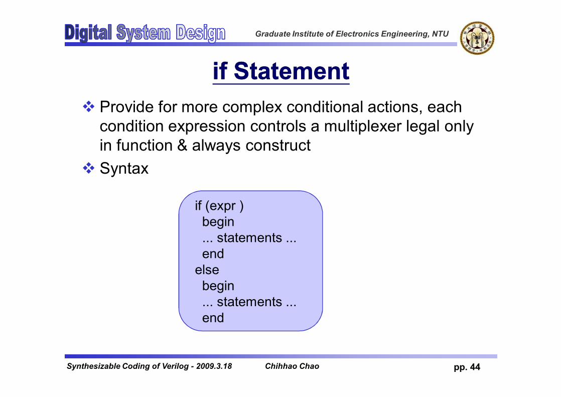
if Statementif Statementv Provide for more complex conditional actions, each
condition expression controls a multiplexer legal only in function & always construct
v Syntax
if (expr )begin... statements ...end
elsebegin... statements ...end
Chihhao Chao

Graduate Institute of Electronics Engineering, NTU
pp. 45Synthesizable Coding of Verilog - 2009.3.18
if Statementif Statementv if statement can be nested
always @(sel1 or sel2 or sel3 or sel4 or in1 or in2 or in3 or in4 or in5)begin
if (sel1) beginif (sel2) out=in1;else out=in2;
endelse if (sel3) beginif (sel4) out=in3;else out=in4;
endelse out=in5;
end
Chihhao Chao

Graduate Institute of Electronics Engineering, NTU
pp. 46Synthesizable Coding of Verilog - 2009.3.18
if Statementif StatementvWhat’s the difference between these two
coding styles?
if sel==4’b1001z = d;
if sel==4’b1001z = d;
Chihhao Chao

Graduate Institute of Electronics Engineering, NTU
pp. 47Synthesizable Coding of Verilog - 2009.3.18
if Statementif Statement
longer critical path, smaller area shorter critical path,
larger area
Chihhao Chao

Graduate Institute of Electronics Engineering, NTU
pp. 48Synthesizable Coding of Verilog - 2009.3.18
case Statementcase StatementvLegal only in the function & always constructvsyntax
Chihhao Chao

Graduate Institute of Electronics Engineering, NTU
pp. 49Synthesizable Coding of Verilog - 2009.3.18
case Statementcase StatementvA case statement is called a full case if all
possible branches are specified.
always @(bcd) begincase (bcd)4'd0:out=3'b001;4'd1:out=3'b010;4'd2:out=3'b100;default:out=3'bxxx;
endcaseend
Chihhao Chao
Graduate Institute of Electronics Engineering, NTU
pp. 50Synthesizable Coding of Verilog - 2009.3.18
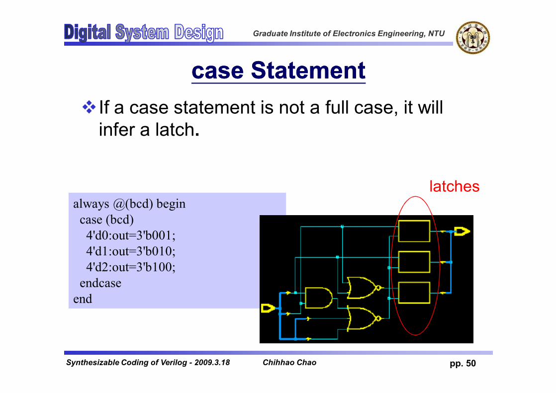
case Statementcase StatementvIf a case statement is not a full case, it will
infer a latch.
always @(bcd) begincase (bcd)4'd0:out=3'b001;4'd1:out=3'b010;4'd2:out=3'b100;
endcaseend
latches
Chihhao Chao

Graduate Institute of Electronics Engineering, NTU
pp. 51Synthesizable Coding of Verilog - 2009.3.18
case Statementcase Statementv If you do not specify all possible branches, but you
know the other branches will never occur, you can use “//synopsys full_case” directive to specify full case
always @(bcd) begincase (bcd) //synopsys full_case4'd0:out=3'b001;4'd1:out=3'b010;4'd2:out=3'b100;
endcaseend
Chihhao Chao

Graduate Institute of Electronics Engineering, NTU
pp. 52Synthesizable Coding of Verilog - 2009.3.18
case Statementcase StatementvNote: the second case item does not modify
reg2, causing it to be inferred as a latch (to retain last value).
Chihhao Chao
Graduate Institute of Electronics Engineering, NTU
pp. 53Synthesizable Coding of Verilog - 2009.3.18
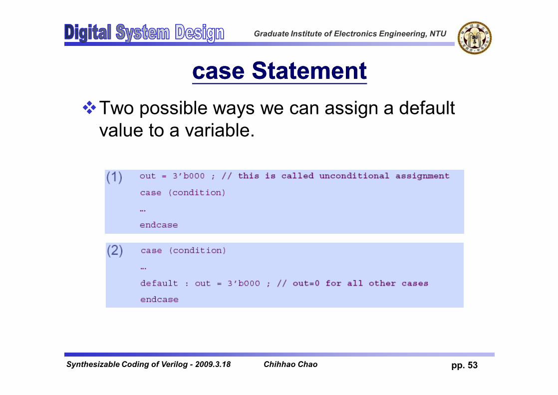
case Statementcase StatementvTwo possible ways we can assign a default
value to a variable.
Chihhao Chao
Graduate Institute of Electronics Engineering, NTU
pp. 54Synthesizable Coding of Verilog - 2009.3.18
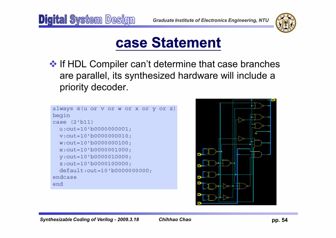
case Statementcase Statementv If HDL Compiler can’t determine that case branches
are parallel, its synthesized hardware will include a priority decoder.
Chihhao Chao
Graduate Institute of Electronics Engineering, NTU
pp. 55Synthesizable Coding of Verilog - 2009.3.18
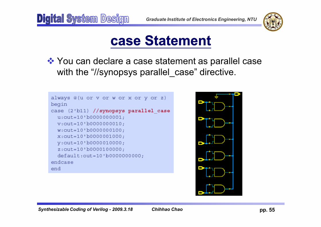
case Statementcase Statementv You can declare a case statement as parallel case
with the “//synopsys parallel_case” directive.
Chihhao Chao

Graduate Institute of Electronics Engineering, NTU
pp. 56Synthesizable Coding of Verilog - 2009.3.18
for Loopfor Loopv Provide a shorter way to express a series of
statements.v Loop index variables must be integer type.v Step, start & end value must be constant.v In synthesis, for loops loops are “unrolled”, and then
synthesized.always@( a or b )beginfor( i=0; i<4; i=i+1 )
c[i] = a[i] & b[i];end
always@( a or b )beginc[0] = a[0] & b[0];c[1] = a[1] & b[1];c[2] = a[2] & b[2];c[3] = a[3] & b[3];
end
Chihhao Chao

Graduate Institute of Electronics Engineering, NTU
pp. 57Synthesizable Coding of Verilog - 2009.3.18
always Blockalways Block
always @( event-expression )beginstatements
end
v If event-expression contains posedge or negedge, flip-flop(register) will be synthesized.
v A variable assigned within an always @ block that is not fully specified will result in latches synthesized.
v In all other cases, combinational logic will be synthesized.
Chihhao Chao

Graduate Institute of Electronics Engineering, NTU
pp. 58Synthesizable Coding of Verilog - 2009.3.18
Infer RegistersInfer RegistersvVerilog template for sequential processesvUse the reset signal to initialize registered signals
Chihhao Chao

Graduate Institute of Electronics Engineering, NTU
pp. 59Synthesizable Coding of Verilog - 2009.3.18
Avoid Combinational FeedbackAvoid Combinational Feedback
Chihhao Chao

Graduate Institute of Electronics Engineering, NTU
pp. 60Synthesizable Coding of Verilog - 2009.3.18
Sensitivity List (1/3)Sensitivity List (1/3)vFor combinational blocks, the sensitivity list
must include every signal that is read by the process.vSignals that appear on the right side of an assign
statement vSignals that appear in a conditional expression
Chihhao Chao

Graduate Institute of Electronics Engineering, NTU
pp. 61Synthesizable Coding of Verilog - 2009.3.18
Sensitivity List (2/3)Sensitivity List (2/3)vInclude a complete
sensitivity list in each of always blocksvIf not, the behavior of the
pre-synthesis design may differ from that of the post-synthesis netlist.
Chihhao Chao

Graduate Institute of Electronics Engineering, NTU
pp. 62Synthesizable Coding of Verilog - 2009.3.18
Sensitivity List (3/3)Sensitivity List (3/3)vFor sequential blocksvThe sensitive list must include the clock signal. vIf an asynchronous reset signal is used, include
reset in the sensitivity list.
vUse only necessary signals in the sensitivity listsvUnnecessary signals in the sensitivity list slow
down simulationChihhao Chao

Graduate Institute of Electronics Engineering, NTU
pp. 63Synthesizable Coding of Verilog - 2009.3.18
Blocking and Nonblocking Assignments(1/3)Blocking and Nonblocking Assignments(1/3)vTwo types of assignmentsvBlocking assignments execute in sequential order.vNonblocking assignments execute concurrently.
vAlways use nonblocking assignments in always@ (posedge clk) blocks.vOtherwise, the simulation behavior of the RTL and
gate-level designs may differ.vSpecifically, blocking assignments can lead to
race conditions and unpredictable behavior in simulations.
Chihhao Chao

Graduate Institute of Electronics Engineering, NTU
pp. 64Synthesizable Coding of Verilog - 2009.3.18
Blocking and Nonblocking Assignments(2/3)Blocking and Nonblocking Assignments(2/3)
Chihhao Chao
Graduate Institute of Electronics Engineering, NTU
pp. 65Synthesizable Coding of Verilog - 2009.3.18
Blocking and Nonblocking Assignments(3/3)Blocking and Nonblocking Assignments(3/3)vWhen modeling sequential logic, use
nonblocking assignments.vWhen modeling combinational logic with an
always block, use blocking assignments.vDo not mix blocking and nonblocking
assignments in the same always block.vDo not make assignments to the same
variable from more than one always block.
Chihhao Chao

Graduate Institute of Electronics Engineering, NTU
pp. 66Synthesizable Coding of Verilog - 2009.3.18
OutlineOutlinevBasic concepts of logic synthesisvSynthesizable Verilog coding subsetvVerilog coding practicesvCoding for readabilityvCoding for synthesisvPartitioning for synthesis
Chihhao Chao

Graduate Institute of Electronics Engineering, NTU
pp. 67Synthesizable Coding of Verilog - 2009.3.18
Register All OutputsRegister All OutputsvFor each subblock of a hierarchical macro
design, register all output signals from the subblock.vMakes output drive strengths and input delays
predictable
Chihhao Chao
Graduate Institute of Electronics Engineering, NTU
pp. 68Synthesizable Coding of Verilog - 2009.3.18
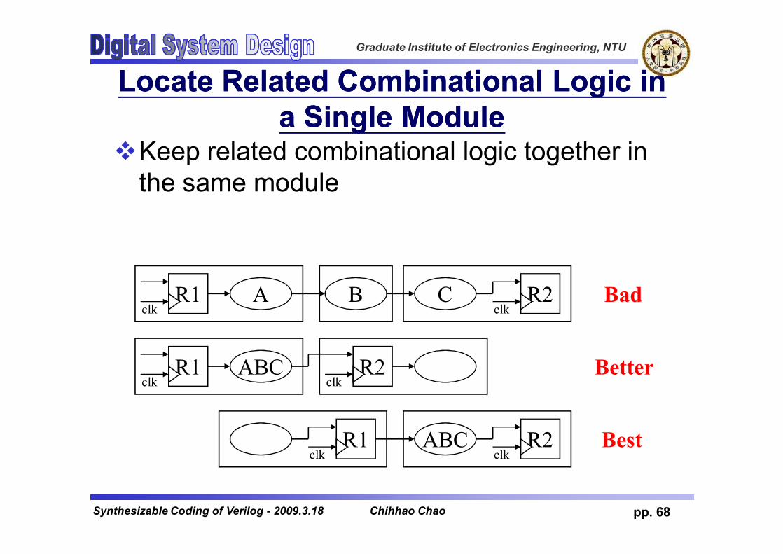
Locate Related Combinational Logic in Locate Related Combinational Logic in a Single Modulea Single Module
vKeep related combinational logic together in the same module
R1clk
A B R2clk
C
R1clk
ABC R2clk
R1clk
R2clk
ABC
Bad
Better
Best
Chihhao Chao

Graduate Institute of Electronics Engineering, NTU
pp. 69Synthesizable Coding of Verilog - 2009.3.18
Separate Modules that Have Different Separate Modules that Have Different Design GoalsDesign Goals
v Synthesis tools can perform speed optimization on the critical path logic, while performing area optimization on the noncritical path logic.
Chihhao Chao
Graduate Institute of Electronics Engineering, NTU
pp. 70Synthesizable Coding of Verilog - 2009.3.18
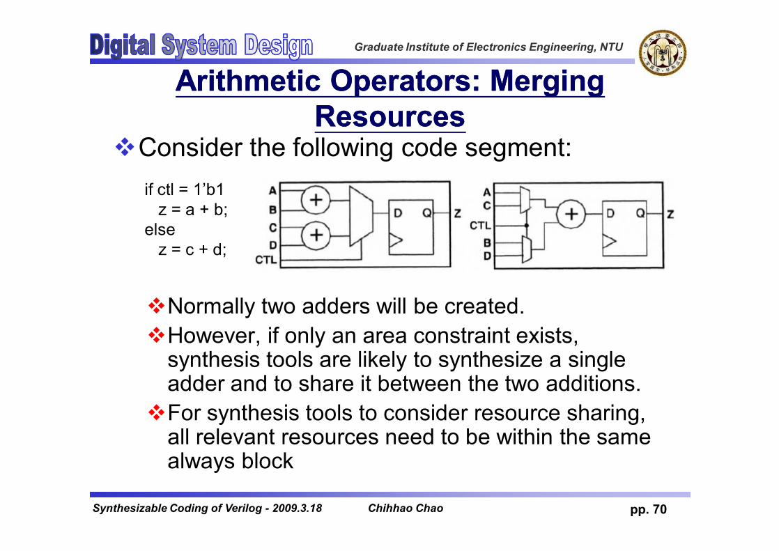
Arithmetic Operators: Merging Arithmetic Operators: Merging ResourcesResources
vConsider the following code segment:
vNormally two adders will be created.vHowever, if only an area constraint exists,
synthesis tools are likely to synthesize a single adder and to share it between the two additions.vFor synthesis tools to consider resource sharing,
all relevant resources need to be within the same always block
if ctl = 1’b1z = a + b;
elsez = c + d;
Chihhao Chao
Graduate Institute of Electronics Engineering, NTU
pp. 71Synthesizable Coding of Verilog - 2009.3.18
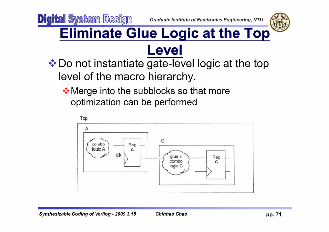
Eliminate Glue Logic at the Top Eliminate Glue Logic at the Top LevelLevel
vDo not instantiate gate-level logic at the top level of the macro hierarchy.vMerge into the subblocks so that more
optimization can be performed
merge
Chihhao Chao


![[ICdesignVN.com]--verilog coding for logic synthesis.pdf](https://static.fdocuments.net/doc/165x107/55cf9b1a550346d033a4bb59/icdesignvncom-verilog-coding-for-logic-synthesispdf.jpg)


