Synthesis of organophilic ZIF-71 membranes for ... · 1 Supporting Information. Synthesis of...
10
1 Supporting Information Synthesis of organophilic ZIF-71 membranes for pervaporation solvent separation Xueliang Dong, Y. S. Lin* School for Engineering of Matter, Transport and Energy, Arizona State University, Tempe, AZ 85287, USA * Corresponding author E-mail: [email protected] Electronic Supplementary Material (ESI) for Chemical Communications This journal is © The Royal Society of Chemistry 2013
Transcript of Synthesis of organophilic ZIF-71 membranes for ... · 1 Supporting Information. Synthesis of...

1
Supporting Information
Synthesis of organophilic ZIF-71 membranes for pervaporation
solvent separation
Xueliang Dong, Y. S. Lin* School for Engineering of Matter, Transport and Energy, Arizona State University, Tempe, AZ 85287, USA * Corresponding author E-mail: [email protected]
Electronic Supplementary Material (ESI) for Chemical CommunicationsThis journal is © The Royal Society of Chemistry 2013
2
1. Experimental details 1.1 Preparation of ZIF-71 crystal ZIF-71 crystals were prepared via three different routes: (1) A mixture of 4,5-dichloroimidazole (dcIm, 0.42 g, 3 mmol, Sigma-Aldrich) and methanol
(15 mL, Alfa Aesar) was dropped into a mixture of Zn(CH3COO)2·2H2O (0.22 g, 1 mmol, Sigma-Aldrich) and methanol (15 mL, Alfa Aesar) at room temperature with stirred vigorously for 2 h.. White ZIF-71 powders were obtained after the precipitates were centrifuged, washed with methanol and dried.
(2) Excess ZnO (Sigma-Aldrich) powders were added into an autoclave (45 ml) with a mixture of 4,5-dichloroimidazole (dcIm, 0.42 g, 3 mmol, Sigma-Aldrich) and methanol (30 mL, Alfa Aesar). The autoclave was heated to 105 oC for 12 h. After cooling, the solution was centrifuged and the precipitates were washed with methanol. The mixture of ZnO and ZIF-71 powders were obtained after drying.
(3) Excess ZnO (Sigma-Aldrich) powders were added into an autoclave (45 ml) with a mixture of 4,5-dichloroimidazole (dcIm, 0.42 g, 3 mmol, Sigma-Aldrich) and dimethylformamide (DMF, 30 mL, Alfa Aesar). The autoclave was heated to 105 oC for 12 h. After cooling, the solution was centrifuged and the precipitates were washed with DMF. The mixture of ZnO and ZIF-71 powders were obtained after drying.
1.2 Preparation of support ZnO powders (<5 µm, Sigma-Aldrich) were uniaxially pressed at 200 MPa to prepare disks with the diameter of 22 mm and thickness of 2 mm. The disks were then sintered at 570 °C for 6 h to form porous support with the normal pore size of ca. 100 nm and the porosity of about 34 %. One side of the support was polished by SiC sandpaper, washed in deionized water, and dried before being used for the growth of ZIF membrane. 1.3 Preparation of ZIF-71 membrane A typical procedure for the synthesis of a ZIF-71 membrane on a ZnO support by the reactive seeding method consisted of two processes.
Seeding process: dcIm (0.196 g, 1.4 mmol) and DMF (26 ml) were mixed and stirred vigorously for 30 min. A ZnO support was placed vertically in a Teflon lined stainless steel autoclave (45 ml) with the solution mixture. The autoclave was heated to 105 oC for 12 h in an oven and then cooled down to room temperature. The support with the ZIF-71 seed layer was washed with DMF and dried.
Secondary growth: the seeded ZnO support was placed vertically into the precursor solution, with a composition of Zn(CH3COO)2·2H2O (0.20 g, 0.9 mmol), dcIm (0.39g, 2.8 mmol) and DMF (26 ml). The autoclave, containing the seeded support and the precursor solution, was heated to 105 oC for 16 h. After cooling, the membrane was washed with DMF and then immersed in methanol for 12h to exchange the DMF. After washing with fresh methanol, the solvent exchange process was repeated again. And then, the membrane was dried at 60 oC and under vacuum.
For the preparation of ZIF-71 membrane with the in situ solvothermal method, the precursor
Electronic Supplementary Material (ESI) for Chemical CommunicationsThis journal is © The Royal Society of Chemistry 2013

3
with a composition of Zn(CH3COO)2·2H2O (0.22 g, 1.0 mmol), dcIm (0.42g, 3.0 mmol) and DMF (26 ml) was prepared. A ZnO support was placed vertically in a Teflon lined stainless steel autoclave (45 ml) with the precursor. The autoclave was heated to 105 oC for 16 h. 1.4 Characterizations The crystal phases of the samples were determined by X-ray diffraction (XRD) with Cu Ka radiation (Bruker, AXS-D8,). Diffraction patterns were collected at room temperature in the range of 5<2θ< 50, with a step width of 0.05 o and a scan rate of 0.2 s per step. The morphologies of the seed, seed layer and membrane were examined by scanning electron microscopy (SEM) (Philips FEI XL-30) after gold deposition. The chemical bonds for various species in the ZIF-71 crystal and ZIF-71 membrane (using the powder scraped from the surface of membrane) were measured in air by ATR-FTIR (NICOLET 4700 FT-IR, Thermo Electron Corporation). The contact angles of water, methanol and ethanol on the ZIF-71 membrane were analyzed by the Contact angle Dropmeter (A100P, MAIST Vision Inspection & Measurement Co. Ltd).
Single gas permeation experiments were performed on the permeation setup shown in Fig. S1. The permeation of gas molecules (He, N2, and SF6) was measured at room temperature (25 oC) through ZIF-71 membranes or supports. The feed side was regulated at different pressures and the permeate side was open to atmosphere. The permeated gas flow rate was measured by a soap film flowmeter.
Fig. S1 Schematic diagram of the single gas separation experimental apparatus.
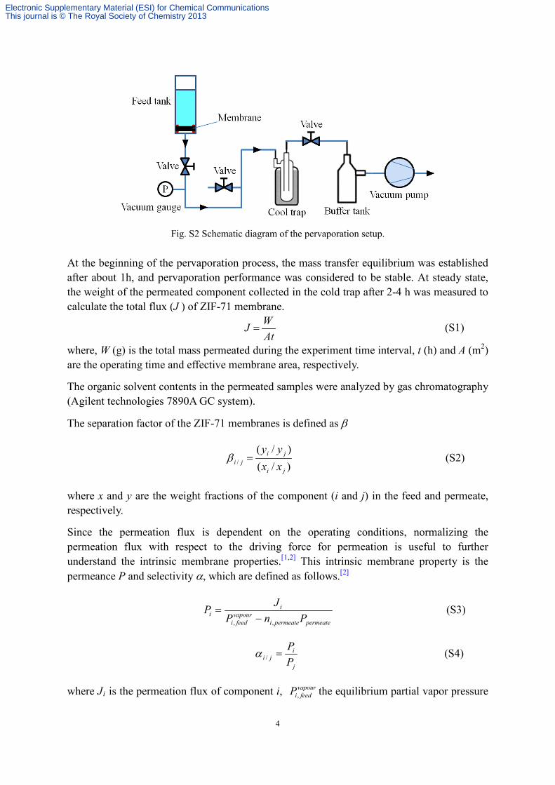
The pervaporation performance of ZIF-71 membrane was measured on a homemade apparatus (Fig. S2). The ZIF-71 membrane was assembled at the bottom of a feed tank with the solution to be separated. The surface of the membrane is up. The support side was connected to the vacuum pump. The vacuum on the permeate side was maintained at about 200 Pa. The permeated vapor was collected in liquid nitrogen traps.
Electronic Supplementary Material (ESI) for Chemical CommunicationsThis journal is © The Royal Society of Chemistry 2013
4
Fig. S2 Schematic diagram of the pervaporation setup.
At the beginning of the pervaporation process, the mass transfer equilibrium was established after about 1h, and pervaporation performance was considered to be stable. At steady state, the weight of the permeated component collected in the cold trap after 2-4 h was measured to calculate the total flux (J ) of ZIF-71 membrane.
AtWJ = (S1)
where, W (g) is the total mass permeated during the experiment time interval, t (h) and A (m2) are the operating time and effective membrane area, respectively.
The organic solvent contents in the permeated samples were analyzed by gas chromatography (Agilent technologies 7890A GC system).
The separation factor of the ZIF-71 membranes is defined as β
)/()/(
/ji
jiji xx
yy=β (S2)
where x and y are the weight fractions of the component (i and j) in the feed and permeate, respectively.
Since the permeation flux is dependent on the operating conditions, normalizing the permeation flux with respect to the driving force for permeation is useful to further understand the intrinsic membrane properties.[1,2] This intrinsic membrane property is the permeance P and selectivity α, which are defined as follows.[2]
permeatepermeatei
vapourfeedi
ii PnP
JP,, −
= (S3)
j
iji P
P=/α (S4)
where Ji is the permeation flux of component i, vapourfeediP , the equilibrium partial vapor pressure
Electronic Supplementary Material (ESI) for Chemical CommunicationsThis journal is © The Royal Society of Chemistry 2013

5
of component i in the feed, ni,permeate the mole fraction of component i in the permeate side and Ppermeate the permeate side pressure, Pi and Pj the permeance of component i and j, respectively.
The partial vapor pressure data required to determine the permeances were calculated using the Antoine and van Laar equations. For ethanol/water and methanol/water systems, the partial vapor pressure data were calculated using the ASPEN software. Reference [1] R. W. Baker, J. G. Wijmans, Y. Huang, J. Membr. Sci., 2010, 348, 346. [2] J. G. Wijmans, J. Membr. Sci., 2003, 220, 1.
Electronic Supplementary Material (ESI) for Chemical CommunicationsThis journal is © The Royal Society of Chemistry 2013

6
2. FT-IR spectra of ZIF-71 powders
Fig. S3 FT-IR spectra of ZIF-71: a) ZIF-71 crystals synthesized using dcIm and Zn(CH3COO)2·H2O with methanol; b) ZIF-71 crystals scraped from the surface of ZIF-71 membrane.
Electronic Supplementary Material (ESI) for Chemical CommunicationsThis journal is © The Royal Society of Chemistry 2013

7
3. Morphology of ZIF-71 membrane prepared by in situ growth
Fig. S4 SEM images of ZIF-71 membranes prepared by the in situ method.
Electronic Supplementary Material (ESI) for Chemical CommunicationsThis journal is © The Royal Society of Chemistry 2013

8
4. Single gas permeation
(a)
(b)
Fig. S5 Single gas permeances of helium, nitrogen and SF6 through the ZIF-71 membrane (a), and helium and nitrogen through zinc oxide support (b) under different feed pressures at 25 oC. The permeate side pressure is 0.1 MPa.
Electronic Supplementary Material (ESI) for Chemical CommunicationsThis journal is © The Royal Society of Chemistry 2013

9
5. Contact angle
(a)
(b)
(c)
Fig. S6 a) static contact angle of water on ZIF-71 membrane; b) dynamic contact angle of ethanol on ZIF-71 membrane; c) dynamic contact angle of methanol on ZIF-71 membrane.
Electronic Supplementary Material (ESI) for Chemical CommunicationsThis journal is © The Royal Society of Chemistry 2013

10
6. Structural stability
Fig. S7 XRD patterns of ZIF-71 membrane: a) before and b) after the ethanol/water, methanol/water and
DMC/methanol pervaporation experiments.
As shown in Fig. S7, no obvious change is observed for the crystal structure of ZIF-71 membrane after the pervaporation experiments, indicating that the membrane is stable in pervaporation environment.
Electronic Supplementary Material (ESI) for Chemical CommunicationsThis journal is © The Royal Society of Chemistry 2013